Sputter and multi-source - caburn-mdc europe
Sputter and multi-source - caburn-mdc europe Sputter and multi-source - caburn-mdc europe
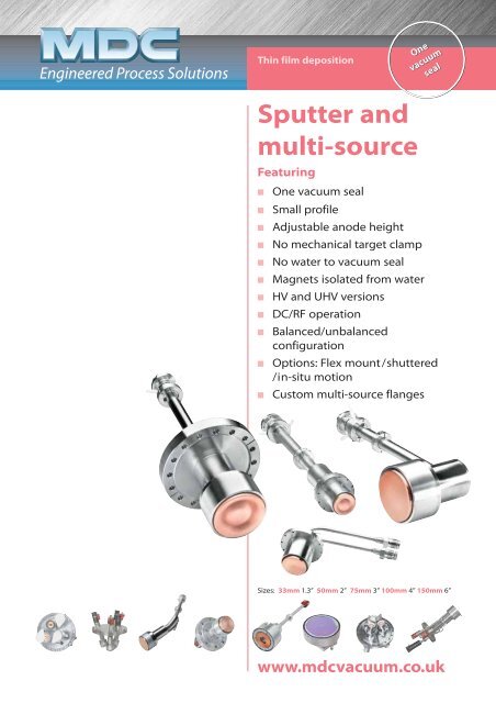
Thin film deposition Sputter and multi-source Featuring One One vacuum vacuum seal ■ One vacuum seal ■ Small profile ■ Adjustable anode height ■ No mechanical target clamp ■ No water to vacuum seal ■ Magnets isolated from water ■ HV and UHV versions ■ DC/RF operation ■ Balanced/unbalanced configuration ■ Options: Flex mount/shuttered /in-situ motion ■ Custom multi-source flanges Sizes: 33mm 1.3” 50mm 2” 75mm 3” 100mm 4” 150mm 6” www.mdcvacuum.co.uk
- Page 2 and 3: 3 The history of MAK ® Sputter sou
- Page 4 and 5: 2 MAK ® Sputter sources The sputte
- Page 6 and 7: 4 Sputter source Introduction MAK
- Page 8 and 9: 6 A N G S T R Angstroms O M S Worki
- Page 10 and 11: 8 A N G S T R Angstroms O M S Worki
- Page 12 and 13: 10 MAK ® Flex mount Options The fl
- Page 14 and 15: 12 Features ■ UHV Compatible ■
- Page 16: Sputter and multi-source www.mdcvac
Thin film deposition<br />
<strong>Sputter</strong> <strong>and</strong><br />
<strong>multi</strong>-<strong>source</strong><br />
Featuring<br />
One One<br />
vacuum vacuum<br />
seal<br />
■ One vacuum seal<br />
■ Small profile<br />
■ Adjustable anode height<br />
■ No mechanical target clamp<br />
■ No water to vacuum seal<br />
■ Magnets isolated from water<br />
■ HV <strong>and</strong> UHV versions<br />
■ DC/RF operation<br />
■ Balanced/unbalanced<br />
configuration<br />
■ Options: Flex mount/shuttered<br />
/in-situ motion<br />
■ Custom <strong>multi</strong>-<strong>source</strong> flanges<br />
Sizes: 33mm 1.3” 50mm 2” 75mm 3” 100mm 4” 150mm 6”<br />
www.<strong>mdc</strong>vacuum.co.uk
3<br />
The history of MAK ® <strong>Sputter</strong> <strong>source</strong>s<br />
Since the 1980’s MeiVac’s US<br />
Components Division has<br />
acquired <strong>multi</strong>ple exclusive<br />
manufacturing <strong>and</strong> distribution<br />
licenses for patented planar<br />
magnetron sputter <strong>source</strong>s from two<br />
prominent Silicon Valley research<br />
laboratories.<br />
With over 6,000 of these <strong>source</strong>s<br />
delivered worldwide, the US<br />
Components Division has become<br />
known as a leading manufacturer of<br />
sputter deposition <strong>source</strong>s, substrate<br />
heaters <strong>and</strong> <strong>and</strong> associated<br />
hardware. Introduced in the 1990’s,<br />
one of the <strong>source</strong>s, the MAK®, rapidly<br />
became a st<strong>and</strong>ard in the industry.<br />
Noted for its simplicity, ease of use<br />
<strong>and</strong> resulting high reliability, the<br />
MAK® <strong>source</strong> has been designed to<br />
present the smallest profile possible<br />
<strong>and</strong> deliver higher deposition rates<br />
than comparable sputter <strong>source</strong>s.<br />
Because of its popularity, the<br />
MAK® <strong>source</strong> has been used in<br />
the development of many of<br />
today’s thin film processes.<br />
The MAK® <strong>source</strong> is produced at<br />
MeiVac’s San Jose, California,<br />
USA facility.
<strong>Sputter</strong> <strong>source</strong>s <strong>and</strong> <strong>multi</strong>-<strong>source</strong><br />
<strong>Sputter</strong> <strong>source</strong>s <strong>and</strong> <strong>multi</strong>-<strong>source</strong><br />
Uniformity distribution 2-3<br />
<strong>Sputter</strong> <strong>source</strong> technical features 4<br />
33mm 1.3” MAK ® 5<br />
50mm 2” MAK ® 6<br />
75mm 3” MAK ® 7<br />
100mm 4” MAK ® 8<br />
150mm 6” MAK ® 9<br />
Flex mount 10<br />
Multi-<strong>source</strong> 11<br />
Substrate heaters 12-13<br />
United MDC Vacuum Limited France MDC Vacuum Products Sarl Germany Tel: +49 (0)2305 947 508<br />
Kingdom Tel: +44 (0)1825 280 450 Tel: +33 (0)437 65 17 50 Tel: +49 (0)2305 947 508<br />
Fax: +44 (0)1825 280 440 Fax: +33 (0)437 65 17 55 Fax: +49 (0)2305 947 510<br />
sales@<strong>mdc</strong>vacuum.co.uk info@<strong>mdc</strong>vacuum.fr sales@<strong>mdc</strong>vacuum.de<br />
Italy Kenosistec Srl Holl<strong>and</strong> Evatec Process Systems BV Russian MSH Technology Limited<br />
Tel: +39 02 9055200 Tel: +31 343 595 470 Federation Tel: +7 (495) 543 60 25<br />
Fax: +31 343 592 294 Fax: +31 343 592 294 Fax: +7 (495) 722 12 90<br />
info<strong>caburn</strong>@kenosistec.it sales@<strong>mdc</strong>vacuum.nl shive@msht.ru
2<br />
MAK ® <strong>Sputter</strong> <strong>source</strong>s<br />
The sputtering process<br />
<strong>Sputter</strong>ing, which is a physical<br />
vapour deposition (PVD)<br />
coating technique, is a<br />
common method of<br />
depositing both metal layers<br />
<strong>and</strong> insulating layers on a<br />
substrate. The layers being<br />
deposited can be elements<br />
such as Cu, Au, etc., alloys such<br />
as AlCu, NiFe, etc. or insulators<br />
such as SiO2, TiN, etc.<br />
Principles of<br />
sputtering<br />
Ions<br />
Electrons<br />
Target atoms<br />
Argon atoms<br />
Growing<br />
film<br />
Typically, a substrate (the item<br />
to be coated) is placed in a<br />
vacuum chamber opposite a target (made of the<br />
material being sputtered). The chamber is<br />
evacuated <strong>and</strong> then backfilled with a process<br />
gas (argon). The gas is ionized with a<br />
positive charge which creates plasma.<br />
Resulting ions are strongly attracted<br />
to the target, which carries a<br />
negative charge. The effect is<br />
a physical process similar to<br />
the interaction of billiard balls<br />
in a confined space. As the relatively large<br />
argon ions impact on the target,<br />
atoms/molecules of target material<br />
are physically removed from the<br />
target. Due to its close<br />
proximity, a majority of the<br />
sputtered atoms/molecules<br />
l<strong>and</strong> on the target. The intent<br />
is for this material to arrive at<br />
the substrate with enough<br />
energy to form a thin,<br />
strongly attracted<br />
film, one<br />
monolayer at<br />
a time.<br />
Uniformity<br />
Uniformity is<br />
heavily dependant on<br />
<strong>source</strong> to substrate<br />
distance <strong>and</strong> the<br />
relationship between<br />
<strong>source</strong> <strong>and</strong> substrate<br />
diameters<br />
All dimensions are nominal in millimetres unless specified.<br />
B Field<br />
Telephone +44 (0)1825 280 450 www.<strong>mdc</strong>vacuum.co.uk<br />
E Field<br />
Legend<br />
Material removed by<br />
ion bombardment<br />
<strong>Sputter</strong> <strong>source</strong>s <strong>and</strong> <strong>multi</strong>-<strong>source</strong><br />
Target (cathode)<br />
negative high voltage<br />
Planar magnetron<br />
sputtering<br />
In conventional diode<br />
sputtering, electrons are<br />
created that escape the<br />
effective plasma area near the<br />
target. Some fly around the<br />
chamber creating undesirable<br />
side effects, such as heating<br />
the tooling. A magnetron<br />
sputtering <strong>source</strong> addresses<br />
the electron problem by<br />
placing magnets behind, <strong>and</strong><br />
sometimes at the sides of the<br />
target. These magnets capture<br />
the escaping electrons <strong>and</strong><br />
confine them to the<br />
immediate vicinity of the<br />
target. This increases the ion current (density of<br />
ionized argon atoms hitting the target) by a factor of 10 over<br />
conventional diode targets, resulting in faster deposition rates<br />
at lower pressures, which help to produce cleaner films.<br />
Film properties<br />
Magnetic<br />
field lines<br />
Captured<br />
electrons<br />
Deposition rate, film structure <strong>and</strong> layer uniformity<br />
of deposition materials are highly dependent on:<br />
■ <strong>Sputter</strong> efficiency of the material<br />
■ Deposition power level<br />
■ Source of substrate distance<br />
■ Process gas<br />
■ Substrate temperature<br />
■ Target erosion<br />
■ Position of anode<br />
■ Process pressure<br />
■ Power type (RF or DC)<br />
■ Angle of incidence<br />
■ Target magnetic permeability<br />
■ Configuration of <strong>source</strong><br />
■ Balance of magnetic fields<br />
Source to Rate Wafer Wafer Cu Watts<br />
MAK ® substrate Å/min diameter Typical diameter Typical target @<br />
model distance copper mm uniformity mm uniformity thickness 5 mTorr<br />
33<br />
50<br />
75<br />
100<br />
150<br />
Cross section of a planar magnetron<br />
Details of typical rates <strong>and</strong> uniformity performances<br />
50.8 1,750<br />
±7%<br />
±20%<br />
50.8<br />
76.2<br />
76.2 975 ±5% ±12%<br />
50.8 6,200<br />
±6%<br />
±16%<br />
50.8<br />
76.2<br />
76.2 2,800 ±3% ±10%<br />
76.2 10,000<br />
±5%<br />
±15%<br />
50.8<br />
101.6<br />
101.6 5,600 ±3% ±10%<br />
101.6 6,470<br />
±5%<br />
±7%<br />
76.2<br />
101.6<br />
152.4 2,900 ±2% ±3%<br />
101.6 12,900<br />
±4%<br />
±12%<br />
101.6<br />
152.4<br />
152.4 5,800 ±2% ±7%<br />
4.7 200<br />
6.35 500<br />
12.7 1000<br />
12.7 2000<br />
12.7 3000
<strong>Sputter</strong> <strong>source</strong>s <strong>and</strong> <strong>multi</strong>-<strong>source</strong><br />
Uniformity of sputtered materials across the<br />
diameter of a substrate as a function of target<br />
Uniformity distribution<br />
Relative rates Cu = 1.0<br />
size <strong>and</strong> <strong>source</strong> to substrate distance. Under identical power <strong>and</strong> geometric conditions<br />
A<br />
N<br />
G<br />
S<br />
T<br />
R<br />
Angstroms<br />
O<br />
M<br />
S<br />
A<br />
N<br />
G<br />
S<br />
T<br />
R<br />
Angstroms<br />
O<br />
M<br />
S<br />
A<br />
N<br />
G<br />
S<br />
T<br />
R<br />
Angstroms<br />
O<br />
M<br />
S<br />
A<br />
N<br />
G<br />
S<br />
T<br />
R<br />
Angstroms<br />
O<br />
M<br />
S<br />
A<br />
N<br />
G<br />
S<br />
T<br />
R<br />
Angstroms<br />
O<br />
M<br />
S<br />
Working distance<br />
50.8<br />
76.2<br />
1,510<br />
1,180<br />
760<br />
Working distance<br />
50.8<br />
76.2<br />
5,550<br />
4,445<br />
2,295<br />
Working distance<br />
76.2<br />
101.6<br />
9,100<br />
7,300<br />
4,650<br />
Working distance<br />
101.6<br />
152.4<br />
6,070<br />
5,840<br />
2,750<br />
Working distance<br />
101.6<br />
152.4<br />
12,200<br />
10,225<br />
5000<br />
885<br />
2,620<br />
5,230<br />
2,780<br />
5500<br />
1,750<br />
76.2 25.4<br />
0<br />
25.4 38.1<br />
MAK<br />
mm<br />
® 1.3” Source<br />
38.1 25.4<br />
0<br />
25.4 38.1<br />
MAK<br />
mm<br />
® 2” Source<br />
50.8 25.4<br />
0<br />
25.4 50.8<br />
MAK<br />
mm<br />
® 3” Source<br />
6,470<br />
50.8 38.1<br />
0<br />
38.1 50.8<br />
MAK<br />
mm<br />
® 4” Source<br />
12,900<br />
5800<br />
6,090<br />
12,180<br />
5520<br />
5,830<br />
10,150<br />
5050<br />
76.2 50.8<br />
0<br />
50.8 76.2<br />
MAK<br />
mm<br />
® 6” Source<br />
975<br />
6,200<br />
2,800<br />
10,000<br />
5,600<br />
2,900<br />
1.520<br />
890<br />
5,580<br />
2,630<br />
9,135<br />
5,210<br />
2,780<br />
1,195<br />
720<br />
4,475<br />
2,270<br />
7,320<br />
4,620<br />
2,715<br />
target materials will sputter at different rates.<br />
The table provides relative rates for common<br />
elements <strong>and</strong> compounds where copper is 1.00.<br />
Ag 2.06<br />
Al 0.73<br />
Al203 0.15<br />
Au 1.76<br />
Be 0.22<br />
Bi 10.00<br />
C 0.05<br />
CdS1010 2.39<br />
CdTe 0.64<br />
Co 0.58<br />
Cr 0.60<br />
Cu 1.00<br />
Dy 1.18<br />
Er 1.00<br />
Fe 0.56<br />
GaAs(110) 1.70<br />
Gd 1.17<br />
Ge 1.05<br />
Glass 0.23<br />
Hf 0.67<br />
Ir 0.61<br />
Mg 0.26<br />
Mgf 0.03<br />
Mn 0.99<br />
Mo 0.53<br />
Nb 0.44<br />
Ni 0.65<br />
Os 0.5<br />
Pb 3.52<br />
Pd 1.31<br />
Pt 0.9<br />
Rb 4.55<br />
Re 0.53<br />
Rh 0.74<br />
Ru 0.66<br />
Sb 3.68<br />
Si 0.39<br />
SiC 0.36<br />
SiO 0.27<br />
SiO2 0.45<br />
Sm 1.14<br />
Sn 1.38<br />
Ta 0.43<br />
Th 0.84<br />
Ti 0.38<br />
U 0.73<br />
V 0.38<br />
W 0.39<br />
Y 0.95<br />
Zr 0.65<br />
All dimensions are nominal in millimetres unless specified.<br />
Telephone +44 (0)1825 280 450 www.<strong>mdc</strong>vacuum.co.uk<br />
3
4<br />
<strong>Sputter</strong> <strong>source</strong><br />
Introduction<br />
MAK ® <strong>Sputter</strong> <strong>source</strong>s<br />
Target is retained by the magnet structure with a simple<br />
keeper. Target exchange is accomplished in moments<br />
without disassembly.<br />
MAK ® <strong>source</strong>s are designed to overcome limitations<br />
commonly found in other <strong>source</strong>s:<br />
Features<br />
■ Water channel is not part of the high voltage path<br />
■ Magnets are not in the water channel<br />
■ Target change does not require <strong>source</strong> disassembly<br />
■ Only one vacuum seal <strong>and</strong> no water to vacuum seals<br />
■ Target requires no clamping or bonding to cathode<br />
■ Magnetic materials may be sputtered with the st<strong>and</strong>ard<br />
magnetic assembly in most applications<br />
■ Operates in DC or RF modes<br />
■ Process pressures 0.5 – 600 m Torr<br />
■ Adjustable anode, improves uniformity, prevents build up<br />
<strong>and</strong> shadowing<br />
■ HV or UHV designs<br />
Magnetron configuration<br />
MDC Vacuum Limited offers a number of options to assist in<br />
achieving desired results. The st<strong>and</strong>ard model MAK ® <strong>source</strong> is<br />
mounted on a 300mm (12˝) long support with a position<br />
clamp included. Water <strong>and</strong> power are contained at<br />
atmospheric pressure within this support. A 19mm/0.75˝<br />
quick coupler vacuum feedthrough is required to integrate<br />
the <strong>source</strong> in the vacuum system <strong>and</strong> position it at the<br />
correct <strong>source</strong> to substrate distance.<br />
St<strong>and</strong>ard mount<br />
101.6 with<br />
manual linear<br />
adjustment<br />
Right angle<br />
50.8 –<br />
manually<br />
adjustable<br />
Flex mount angular<br />
50.8 – manually<br />
adjustable<br />
All dimensions are nominal in millimetres unless specified.<br />
Telephone +44 (0)1825 280 450 www.<strong>mdc</strong>vacuum.co.uk<br />
50mm<br />
Flange<br />
mounted<br />
Target<br />
Cathode<br />
(cooling<br />
surface)<br />
Magnet<br />
return<br />
<strong>Sputter</strong> <strong>source</strong>s <strong>and</strong> <strong>multi</strong>-<strong>source</strong><br />
Cathode<br />
Water line<br />
Optional <strong>source</strong>s <strong>and</strong> features<br />
AIN<br />
insulator<br />
Cooling<br />
block<br />
Keeper<br />
Magnets<br />
Anode<br />
Power feedthrough<br />
■ Gas injection, to deliver process gas directly to the area of<br />
the target, reducing residual gas interaction with the<br />
sputtering process<br />
■ Right angle flex mount, 0-45 degree angular adjustment<br />
■ Low profile, through wall<br />
■ Externally adjustable ‘in-situ’ angular <strong>and</strong> linear <strong>source</strong>s<br />
■ RF <strong>and</strong> DC power supplies <strong>and</strong> RF matching networks<br />
■ Custom tailored flange mounted packages<br />
■ Flange type <strong>and</strong> mount geometry specified by customer<br />
■ Shutters <strong>and</strong> shielding<br />
■ Rotary motion feedthrough
<strong>Sputter</strong> <strong>source</strong>s <strong>and</strong> <strong>multi</strong>-<strong>source</strong><br />
Specifications<br />
Source dimensions 33mm (1.3”) MAK ®<br />
Vertical size 113mm<br />
Outside diameter 38mm<br />
Mounting<br />
Flange DN63CF / 4.5 OD” (min)<br />
Feedthrough 19mm quick coupler<br />
Target specifications<br />
Target diameter 33mm<br />
Target thickness (maximum) 5.7mm<br />
Target mounting Magnetic<br />
Magnetic materials Yes<br />
Magnet design<br />
Type Nd/Fe B<br />
Configuration Balanced<br />
Operation specifications<br />
DC Max power 350W<br />
RF Max power 200W<br />
Cathode voltage (volts) 200-1000V<br />
Discharge current (max amps) 1.00A<br />
Operating pressure (mtorr) 0.5-600<br />
Cooling water<br />
Flow rate 0.6 gpm<br />
Conductivity No requirement<br />
33mm 1.3” typical rates <strong>and</strong> uniformity performance<br />
Working Uniformity<br />
distance Rate A/min 50.8 dia. 76.2 dia.<br />
50.8 1,750 ±7% ±20%<br />
76.2 975 ±5% ±12%<br />
33.0mm diameter 4.7 thick Cu target 3000W @ 5 mTorr<br />
A<br />
N<br />
G<br />
S<br />
T<br />
R<br />
Angstroms<br />
O<br />
M<br />
S<br />
Working distance<br />
50.8<br />
76.2<br />
1,510<br />
1,180<br />
760<br />
885<br />
1,750<br />
975<br />
1.520<br />
1,195<br />
76.2 25.4<br />
0<br />
mm<br />
25.4 38.1<br />
890<br />
720<br />
33mm 1.3” MAK ®<br />
Description<br />
Source<br />
Vertical<br />
Horizontal<br />
Options<br />
33mm 1.3” MAK ®<br />
113.0<br />
Flange mounting options<br />
DN100CF<br />
DN160CF<br />
Accessories<br />
Ø19.1<br />
UHV<br />
Flex mount<br />
Non-st<strong>and</strong>ard mounting tube length*<br />
38.1<br />
Thermal paste (15gm)<br />
Quick disconnect for 25.4 (1”) baseplate<br />
Quick disconnect for DN40KF<br />
Quick disconnect for DN40CF<br />
Quick coupler feedthrough on DN63CF<br />
Quick coupler feedthrough on DN100CF<br />
* Please advise tube length<br />
Reference<br />
Fixed<br />
anode<br />
Ø56.8<br />
305mm<br />
st<strong>and</strong>ard<br />
custom<br />
lengths<br />
available<br />
MAK-130-V<br />
MAK-130-H<br />
UHV<br />
FM2<br />
NSL<br />
CF100KIT<br />
CF160KIT<br />
TP-832<br />
DBF-75<br />
K40XDS-75<br />
FDS-75<br />
QC-833-450<br />
QC-833-600<br />
HN<br />
connector<br />
Part<br />
number €<br />
2701000<br />
2701001<br />
-331<br />
-332<br />
-333<br />
2701105<br />
2701104<br />
2700600<br />
650005<br />
734027<br />
412008<br />
2703100<br />
27003101<br />
2627<br />
2801<br />
3234<br />
2945<br />
POA<br />
POA<br />
POA<br />
72<br />
294<br />
90<br />
116<br />
488<br />
565<br />
All dimensions are nominal in millimetres unless specified.<br />
Telephone +44 (0)1825 280 450 www.<strong>mdc</strong>vacuum.co.uk<br />
5
6<br />
A<br />
N<br />
G<br />
S<br />
T<br />
R<br />
Angstroms<br />
O<br />
M<br />
S<br />
Working distance<br />
50.8<br />
76.2<br />
5,550<br />
4,445<br />
2,295<br />
50mm 2” MAK ®<br />
Specifications<br />
Source dimensions 50mm (2”) MAK ®<br />
Vertical size 99mm<br />
Outside diameter 59mm<br />
Mounting<br />
Flange DN63CF / 4.5” OD (min)<br />
Feedthrough 19 quick coupler<br />
Target specifications<br />
Target diameter 51mm<br />
Target thickness (maximum) 7.9mm<br />
Target mounting Magnetic<br />
Magnetic materials Yes<br />
Magnet design<br />
Type Nd/Fe B<br />
Configuration Balanced/Unbalanced<br />
Operation specifications<br />
DC Max power 1000W<br />
RF Max power 400W<br />
Cathode voltage (volts) 200-1000V<br />
Discharge current (max amps) 3A<br />
Operating pressure (mtorr) 0.5-600<br />
Cooling water<br />
Flow rate 0.8 gpm<br />
Conductivity No requirement<br />
50mm 2” typical rates <strong>and</strong> uniformity performance<br />
Working Uniformity<br />
distance Rate A/min 50.8 dia. 76.2 dia.<br />
50.8 6200 ±6% ±16%<br />
76 2800 ±3% ±10%<br />
50.8mm diameter 6.35 thick Cu target 3000W @ 5 mTorr<br />
2,620<br />
6,200<br />
2,800<br />
5,580<br />
2,630<br />
38.1 25.4<br />
0<br />
mm<br />
25.4 38.1<br />
All dimensions are nominal in millimetres unless specified.<br />
4,475<br />
2,270<br />
Telephone +44 (0)1825 280 450 www.<strong>mdc</strong>vacuum.co.uk<br />
50mm 2” MAK ®<br />
Description<br />
Source<br />
Vertical<br />
Horizontal<br />
Options<br />
Accessories<br />
<strong>Sputter</strong> <strong>source</strong>s <strong>and</strong> <strong>multi</strong>-<strong>source</strong><br />
99.3<br />
Ø19.1<br />
UHV<br />
Flex mount<br />
Non-st<strong>and</strong>ard mounting tube length*<br />
Ø59.2<br />
Thermal paste (15gm)<br />
Quick disconnect for 25.4 (1”) baseplate<br />
Quick disconnect for DN40KF<br />
Quick disconnect for DN40CF<br />
Quick coupler feedthrough on DN63CF<br />
Quick coupler feedthrough on DN100CF<br />
* Please advise tube length<br />
Reference<br />
Anode height<br />
adjustable to<br />
target thickness<br />
Ø38.1<br />
305mm<br />
st<strong>and</strong>ard<br />
custom<br />
lengths<br />
available<br />
MAK-200-V<br />
MAK-200-H<br />
UHV<br />
FM2<br />
NSL<br />
TP-832<br />
DBF-75<br />
K40XDS-75<br />
FDS-75<br />
QC-833-450<br />
QC-833-600<br />
HN<br />
connector<br />
Part<br />
number €<br />
2701002<br />
2701003<br />
-331<br />
-332<br />
-333<br />
2700600<br />
650005<br />
734027<br />
412008<br />
2703100<br />
27003101<br />
2627<br />
2801<br />
3234<br />
2945<br />
POA<br />
72<br />
294<br />
90<br />
116<br />
488<br />
565
<strong>Sputter</strong> <strong>source</strong>s <strong>and</strong> <strong>multi</strong>-<strong>source</strong><br />
Specifications<br />
Source dimensions 75mm (3”) MAK ®<br />
Vertical size 110mm<br />
Outside diameter 86mm<br />
Mounting<br />
Flange DN100CF / 6” OD (min)<br />
Feedthrough 19mm quick coupler<br />
Target specifications<br />
Target diameter 76.2mm<br />
Target thickness (maximum) 15.9mm<br />
Target mounting Magnetic<br />
Magnetic materials Yes<br />
Magnet design<br />
Type Nd/Fe B<br />
Configuration Balanced/Unbalanced<br />
Operation specifications<br />
DC Max power 2000W<br />
RF Max power 750W<br />
Cathode voltage (volts) 200-1000V<br />
Discharge current (max amps) 5A<br />
Operating pressure (mtorr) 0.5-600<br />
Cooling water<br />
Flow rate 0.8 gpm<br />
Conductivity No requirement<br />
75mm 3” typical rates <strong>and</strong> uniformity performance<br />
Working Uniformity<br />
distance Rate A/min 50.8 dia. 101.6 dia.<br />
76.2 10,000 ±5% ±15%<br />
101.6 5,600 ±3% ±10%<br />
76.2mm diameter 12.7 thick Cu target 3000W @ 5 mTorr<br />
A<br />
N<br />
G<br />
S<br />
T<br />
R<br />
Angstroms<br />
O<br />
M<br />
S<br />
Working distance<br />
76.2<br />
101.6<br />
9,100<br />
7,300<br />
4,650<br />
5,230<br />
10,000<br />
5,600<br />
9,135<br />
5,210<br />
7,320<br />
4,620<br />
50.8 25.4<br />
0<br />
mm<br />
25.4 50.8<br />
75mm 3” MAK ®<br />
110.5<br />
75mm 3” MAK ®<br />
Description<br />
Source<br />
Vertical<br />
Horizontal<br />
Options<br />
Accessories<br />
Ø19.1<br />
UHV<br />
Flex mount<br />
Non-st<strong>and</strong>ard mounting tube length*<br />
Ø85.9<br />
Thermal paste (15gm)<br />
Quick disconnect for 25.4 (1”) baseplate<br />
Quick disconnect for DN40KF<br />
Quick disconnect for DN40CF<br />
Quick coupler feedthrough on DN63CF<br />
Quick coupler feedthrough on DN100CF<br />
* Please advise tube length<br />
Reference<br />
MAK-300-V<br />
MAK-300-H<br />
UHV<br />
FM2<br />
NSL<br />
TP-832<br />
DBF-75<br />
K40XDS-75<br />
FDS-75<br />
QC-833-450<br />
QC-833-600<br />
Anode height<br />
adjustable to<br />
target thickness<br />
Ø57.2<br />
305mm<br />
st<strong>and</strong>ard<br />
custom<br />
lengths<br />
available<br />
HN<br />
connector<br />
Part<br />
number €<br />
2703000<br />
2703001<br />
-331<br />
-332<br />
-333<br />
2700600<br />
650005<br />
734027<br />
412008<br />
2703100<br />
27003101<br />
3133<br />
3422<br />
3802<br />
3560<br />
POA<br />
72<br />
294<br />
90<br />
116<br />
488<br />
565<br />
All dimensions are nominal in millimetres unless specified.<br />
Telephone +44 (0)1825 280 450 www.<strong>mdc</strong>vacuum.co.uk<br />
7
8<br />
A<br />
N<br />
G<br />
S<br />
T<br />
R<br />
Angstroms<br />
O<br />
M<br />
S<br />
Working distance<br />
101.6<br />
152.4<br />
6,070<br />
5,840<br />
2,750<br />
101mm 4” MAK ®<br />
Specifications<br />
Source dimensions 100mm (4”) MAK ®<br />
Vertical size 117mm<br />
Outside diameter 113mm<br />
Mounting<br />
Flange DN160CF / 8” OD (min)<br />
Feedthrough 19mm quick coupler<br />
Target specifications<br />
Target diameter 102mm<br />
Target thickness (maximum) 19.1mm<br />
Target mounting Magnetic<br />
Magnetic materials Yes<br />
Magnet design<br />
Type Nd/Fe B<br />
Configuration Balanced/Unbalanced<br />
Operation specifications<br />
DC Max power 3000W<br />
RF Max power 1200W<br />
Cathode voltage (volts) 200-1000V<br />
Discharge current (max amps) 7A<br />
Operating pressure (mtorr) 0.5-600<br />
Cooling water<br />
Flow rate 1.0 gpm<br />
Conductivity No requirement<br />
100mm 4” typical rates <strong>and</strong> uniformity performance<br />
Working Uniformity<br />
distance Rate A/min 76.2 dia. 101.6 dia.<br />
101.6 6,480 ±5% ±7%<br />
152.4 2,900 ±2% ±3%<br />
101.6mm diameter 12.7 thick Cu target 3000W @ 5 mTorr<br />
2,780<br />
6,470<br />
2,900<br />
6,090<br />
2,780<br />
50.8 38.1<br />
0<br />
mm<br />
38.1 50.8<br />
All dimensions are nominal in millimetres unless specified.<br />
5,830<br />
2,715<br />
Telephone +44 (0)1825 280 450 www.<strong>mdc</strong>vacuum.co.uk<br />
116.8<br />
75mm 4” MAK ®<br />
Description<br />
Source<br />
Vertical<br />
Horizontal<br />
Options<br />
Accessories<br />
<strong>Sputter</strong> <strong>source</strong>s <strong>and</strong> <strong>multi</strong>-<strong>source</strong><br />
Ø19.1<br />
UHV<br />
Flex mount<br />
Non-st<strong>and</strong>ard mounting tube length*<br />
113.0<br />
Thermal paste (15gm)<br />
Quick disconnect for 25.4 (1”) baseplate<br />
Quick disconnect for DN40KF<br />
Quick disconnect for DN40CF<br />
Quick coupler feedthrough on DN63CF<br />
Quick coupler feedthrough on DN100CF<br />
* Please advise tube length<br />
Reference<br />
MAK-400-V<br />
MAK-400-H<br />
UHV<br />
FM2<br />
NSL<br />
TP-832<br />
DBF-75<br />
K40XDS-75<br />
FDS-75<br />
QC-833-450<br />
QC-833-600<br />
305mm<br />
st<strong>and</strong>ard<br />
custom<br />
lengths<br />
available<br />
Anode<br />
height<br />
adjustable<br />
to target<br />
thickness<br />
Ø57.2<br />
HN<br />
connector<br />
Part<br />
number €<br />
2703005<br />
2703006<br />
-331<br />
-332<br />
-333<br />
2700600<br />
650005<br />
734027<br />
412008<br />
2703100<br />
27003101<br />
4043<br />
4523<br />
4764<br />
4523<br />
POA<br />
72<br />
294<br />
90<br />
116<br />
488<br />
565
<strong>Sputter</strong> <strong>source</strong>s <strong>and</strong> <strong>multi</strong>-<strong>source</strong><br />
Specifications<br />
Source dimensions 152mm (6”) MAK ®<br />
Vertical size 171mm<br />
Outside diameter 166mm<br />
Mounting<br />
Flange DN200CF / 10” OD (min)<br />
Feedthrough 32mm quick coupler<br />
Target specifications<br />
Target diameter 152.4mm<br />
Target thickness (maximum) 25.4mm<br />
Target mounting Magnetic<br />
Magnetic materials Yes<br />
Magnet design<br />
Type Nd/Fe B<br />
Configuration Balanced/Unbalanced<br />
Operation specifications<br />
DC Max power 6000W<br />
RF Max power 2000W<br />
Cathode voltage (volts) 200-1000V<br />
Discharge current (max amps) 10A<br />
Operating pressure (mtorr) 0.5-600<br />
Cooling water<br />
Flow rate 2.0 gpm<br />
Conductivity No requirement<br />
150mm 6” typical rates <strong>and</strong> uniformity performance<br />
Working Uniformity<br />
distance Rate A/min 101.6 dia. 152.4 dia.<br />
101.6 13,000 ±4% ±12%<br />
152.4 5,800 ±2% ±7%<br />
152.4mm diameter 12.7 thick Cu target 3000W @ 5 mTorr<br />
A<br />
N<br />
G<br />
S<br />
T<br />
R<br />
Angstroms<br />
O<br />
M<br />
S<br />
Working distance<br />
101.6<br />
152.4<br />
12,200<br />
10,225<br />
5000<br />
5500<br />
12,900<br />
5800<br />
12,180<br />
5520<br />
10,150<br />
5050<br />
76.2 50.8<br />
0<br />
mm<br />
50.8 76.2<br />
171.5<br />
152mm 6” MAK ®<br />
Ø114.3<br />
150mm 6” MAK ®<br />
Description<br />
Source<br />
Vertical<br />
Options<br />
Accessories<br />
Ø19.1<br />
UHV<br />
Flex mount<br />
Non-st<strong>and</strong>ard mounting tube length*<br />
166.4<br />
Thermal paste (15gm)<br />
Quick disconnect for 25.4 (1”) baseplate<br />
Quick disconnect for DN40KF<br />
Quick disconnect for DN40CF<br />
Quick coupler feedthrough on DN63CF<br />
Quick coupler feedthrough on DN100CF<br />
* Please advise tube length<br />
Reference<br />
MAK-600-V<br />
UHV<br />
FM2<br />
NSL<br />
TP-832<br />
DBF-75<br />
K40XDS-75<br />
FDS-75<br />
QC-833-450<br />
QC-833-600<br />
305mm<br />
st<strong>and</strong>ard<br />
custom<br />
lengths<br />
available<br />
HN<br />
connector<br />
Anode<br />
height<br />
adjustable<br />
to target<br />
thickness<br />
Part<br />
number €<br />
2703004 6728<br />
-331<br />
-332<br />
-333<br />
2700600<br />
650005<br />
734027<br />
412008<br />
2703100<br />
27003101<br />
7690<br />
POA<br />
POA<br />
72<br />
294<br />
90<br />
116<br />
488<br />
565<br />
All dimensions are nominal in millimetres unless specified.<br />
Telephone +44 (0)1825 280 450 www.<strong>mdc</strong>vacuum.co.uk<br />
9
10<br />
MAK ® Flex mount<br />
Options<br />
The flex mount feedthrough allows for angular adjustment to<br />
the MAK’s sputtering attitude. Use of a welded formed<br />
bellows <strong>and</strong> special support bracket, any angle from 0 to 30°<br />
is firmly held in place. Power is applied thru a coaxial cable;<br />
thus assuring RF continuity.<br />
In-situ linear movement features<br />
■ Provides target to substrate distance change without<br />
breaking vacuum<br />
■ Adaptable to 33mm (1.3”) thru 102mm (4”) MAK ®<br />
■ 25 – 152mm linear travel<br />
■ Welded bellows<br />
■ Bakeable to 120°C<br />
■ UHV Compatible<br />
203.2 CF<br />
85.7 CF<br />
Bellows<br />
50.8 <strong>source</strong><br />
Ø19.1<br />
Ø19.1 quick couple<br />
for support only<br />
152.4 extension<br />
All dimensions are nominal in millimetres unless specified.<br />
Telephone +44 (0)1825 280 450 www.<strong>mdc</strong>vacuum.co.uk<br />
Magnet array<br />
<strong>Sputter</strong> <strong>source</strong>s <strong>and</strong> <strong>multi</strong>-<strong>source</strong><br />
View<br />
rotated 90°<br />
157<br />
218<br />
305mm st<strong>and</strong>ard<br />
custom lengths<br />
available<br />
Performance adaptability<br />
The single piece cathode assembly permits change of the<br />
magnetic structure without disassembly of the MAK ® .<br />
Performance requirements from excellent uniformity, with<br />
good target utilization to – high rates, with maximum target<br />
thickness is achieved. The magnetic array is field changeable.<br />
Magnetic material sputtering<br />
Direct attachment to the active cathode, without use of a<br />
magnetic housing, provides a small free space between<br />
target <strong>and</strong> magnets. This places a stronger magnetic flux at<br />
the target surface allowing sputtering of magnetic material<br />
as st<strong>and</strong>ard.<br />
In-situ, externally<br />
adjustable (under vacuum)<br />
linear 76mm or angular<br />
76mm
<strong>Sputter</strong> <strong>source</strong>s <strong>and</strong> <strong>multi</strong>-<strong>source</strong><br />
Multi-<strong>source</strong> design examples<br />
Project/process specific<br />
custom packages including<br />
■ Sources:<br />
■ St<strong>and</strong>ard with linear adjustment<br />
■ Flexmount internally adjustable<br />
angular<br />
■ In-situ externally adjustable linear<br />
■ In-situ externally adjustable angular<br />
■ Shutters<br />
■ Shields<br />
■ Gas injection<br />
■ 33.0, 50.8, 76.2, 101.6, 152.4 <strong>source</strong>s<br />
(1.3” 2” 3” 4” 6”)<br />
■ Two or more guns on a flange<br />
■ 203.2 – 609.6 (8”–24”) CF, ISO, ANSI<br />
Custom <strong>multi</strong>-<strong>source</strong><br />
assembly with shutters<br />
■ 3 x 50.8 sputtering <strong>source</strong>s<br />
■ Shown with fixed flange to target<br />
distance<br />
■ Customer specified <strong>source</strong> angle<br />
■ Shown mounted on metal seal<br />
ConFlat ® DN160CF flange<br />
■ 2 x <strong>source</strong>s shown with targets <strong>and</strong><br />
one without target<br />
■ With optional non-cross deposition<br />
shields<br />
■ Includes shutters<br />
RF Power supplies,<br />
matching networks<br />
■ 300W, 600W, 1000W RF<br />
■ CE marked<br />
■ Programmable<br />
■ Air cooled<br />
■ RS-232 / 485<br />
■ RF DC voltage control<br />
Multi-<strong>source</strong><br />
DC Power supplies<br />
■ 500W, 1KW, 1.5KW, 2.5KW, 5KW<br />
■ Pulsed DC available with 5KW<br />
■ Arc suppression circuitry<br />
■ Some CE marked configurations<br />
available<br />
■ Regulation in power, voltage, <strong>and</strong><br />
current modes<br />
Custom <strong>multi</strong>-<strong>source</strong> assembly with shutters<br />
All dimensions are nominal in millimetres unless specified.<br />
Telephone +44 (0)1825 280 450 www.<strong>mdc</strong>vacuum.co.uk<br />
11
12<br />
Features<br />
■ UHV Compatible<br />
■ 0 2 Compatible<br />
■ Electrical bias capability<br />
Substrate heaters<br />
SU-400-NC wafer heater block<br />
Heaters are configured for two general types of<br />
application, samples <strong>and</strong> wafers<br />
■ Sample blocks may be drilled <strong>and</strong> tapped for sample holding clips<br />
Note this per customer specification at an additional charge<br />
■ Sample blocks are made of Haynes metal <strong>and</strong> must be prebaked at<br />
atmosphere by the customer at or exceeding the desired operating<br />
temperature prior to use<br />
■ Haynes metal heater blocks are compatible with silver thermal paste, which<br />
is sold as an accessory<br />
■ Wafer blocks are Inconel metal <strong>and</strong> are wafer size specific<br />
■ Wafer pockets are machined into the surface of the heater<br />
■ Inconel is not compatible with silver thermal paste.<br />
■ Unprecedented temperature uniformity<br />
Applications<br />
■ <strong>Sputter</strong>ing<br />
■ Laser ablation<br />
■ Ion beam deposition<br />
■ ERC, MOCVD <strong>and</strong> others<br />
All dimensions are nominal in millimetres unless specified.<br />
Telephone +44 (0)1825 280 450 www.<strong>mdc</strong>vacuum.co.uk<br />
<strong>Sputter</strong> <strong>source</strong>s <strong>and</strong> <strong>multi</strong>-<strong>source</strong><br />
SU-300-HH sample heater block<br />
Optional accessories<br />
Deluxe feedthrough <strong>and</strong> mounting st<strong>and</strong><br />
■ Adjustable mounting bracket with X, Y, Z<br />
movement<br />
■ 2 x type S thermocouple leads<br />
■ 2 x power pins<br />
■ Mounted on a DN40CF, DN63CF or<br />
DN100CF rotatable<br />
Hook-up kit<br />
■ Type S thermocouple 457mm leadwire<br />
■ 2 x 1.27mm OFHC copper power leads<br />
457mm long<br />
■ Ceramic tubes <strong>and</strong> beads for insulation<br />
<strong>and</strong> protection from plasma
<strong>Sputter</strong> <strong>source</strong>s <strong>and</strong> <strong>multi</strong>-<strong>source</strong><br />
Part number<br />
Reference<br />
Stage type<br />
Size in mm<br />
Dimensions in mm<br />
A<br />
B<br />
C<br />
D<br />
E<br />
Maximum temperature<br />
Temperature uniformity<br />
Area of uniformity<br />
Temperature reliability<br />
Ramp time to 950°C<br />
Cool down time<br />
Maximum current<br />
Maximum voltage<br />
Input power<br />
Heater resistance<br />
Heater material<br />
A<br />
D<br />
B<br />
E<br />
C<br />
Substrate heaters<br />
Description<br />
Details<br />
Substrate heaters<br />
See details of typical rates /uniformity performances below<br />
See details of typical rates/uniformity performances below<br />
See details of typical rates/uniformity performances below<br />
See details of typical rates/uniformity performances below<br />
See details of typical rates/uniformity performances below<br />
Tapped hole<br />
Reference<br />
SU-200HH<br />
SU-200IH<br />
SU-300HH<br />
SU-400IH<br />
SU-600IH<br />
Part<br />
number<br />
2706002<br />
2706003<br />
2706004<br />
2706005<br />
2706006<br />
See details of typical rates/uniformity performances below TH<br />
-335<br />
Accessories<br />
Mounting feedthrough DN40CF<br />
Mounting feedthrough DN63CF<br />
Mounting feedthrough DN100CF<br />
Hook up kit ‘K’ TC wire<br />
Hook up kit ‘S’ TC wire<br />
Deluxe mounting feedthrough DN40CF<br />
Deluxe mounting feedthrough DN63CF<br />
Deluxe mounting feedthrough DN100CF<br />
Details of typical rates <strong>and</strong> uniformity performances<br />
SU-905-C40<br />
SU-905-C63<br />
SU-905-C100<br />
SU-918-K<br />
SU-918-S<br />
SU-925-C40<br />
SU-925-C63<br />
SU-925-C100<br />
2706103<br />
2706104<br />
2706105<br />
2706108<br />
2706109<br />
2706111<br />
2706112<br />
2706113<br />
2706002 2706003 2706004 2706005 2706006<br />
SU-200HH SU-200IH SU-300HH SU-400IH SU-600IH<br />
Sample Wafer Sample Wafer Wafer<br />
50.8 50.8 76.2 101.6 152.4<br />
Refer to sketches Refer to sketches Refer to sketches Refer to sketches Refer to sketches<br />
63.5 76.2 88.9 127 171.5<br />
84.6 88.4 97.3 142.2 187.5<br />
60.2 60.2 60.2 83.8 83.8<br />
53.8 66.5 66.5 76.2 76.2<br />
35.1 35.1 35.1 58.4 58.4<br />
950°C 950°C 950°C 950°C 950°C<br />
+/–1% +/–1% +/–1% +/–2% +/–2%<br />
Centre 31.8 dia. 50.8 dia. Centre 57.2 dia. 101.6 dia. 152.4 dia.<br />
12°C 12°C 12°C 13°C 13°C<br />
12 minutes 12 minutes 13 minutes 22 minutes 30 minutes<br />
35 minutes 35 minutes 40 minutes 3 hours 4 hours<br />
10A 10A 9A 14A 14A<br />
45V 45V 85V 85V 135V<br />
AC/DC AC/DC AC/DC AC/DC AC/DC<br />
5 ohms 5 ohms 10 ohms 6 ohms 10 ohms<br />
Haynes Inconel Haynes Inconel Inconel<br />
All dimensions are nominal in millimetres unless specified.<br />
Telephone +44 (0)1825 280 450 www.<strong>mdc</strong>vacuum.co.uk<br />
€<br />
3003<br />
3003<br />
3794<br />
7182<br />
9235<br />
308<br />
508<br />
950<br />
1022<br />
164<br />
452<br />
1817<br />
1817<br />
1858<br />
13
<strong>Sputter</strong> <strong>and</strong> <strong>multi</strong>-<strong>source</strong><br />
www.<strong>mdc</strong>vacuum.co.uk<br />
United Kingdom<br />
MDC Vacuum Limited<br />
Tel: +44 (0)1825 280 450<br />
Fax: +44 (0)1825 280 440<br />
sales@<strong>mdc</strong>vacuum.co.uk<br />
France<br />
MDC Vacuum Products Sarl<br />
Tel: +33 (0)437 65 17 50<br />
Fax: +33 (0)437 65 17 55<br />
info@<strong>mdc</strong>vacuum.fr<br />
Germany<br />
Tel: +49 (0)2305 947 508<br />
Tel: +49 (0)4931 930 5245<br />
Fax: +49 (0)2305 947 510<br />
sales@<strong>mdc</strong>vacuum.de<br />
Holl<strong>and</strong><br />
Evatec Process Systems BV<br />
Tel: +31 343 595 470<br />
Fax: +31 343 592 294<br />
sales@<strong>mdc</strong>vacuum.nl<br />
Italy<br />
Kenosistec Srl<br />
Tel: +39 02 9055200<br />
Fax: +39 02 9052984<br />
info<strong>caburn</strong>@kenosistec.it<br />
Thin film deposition<br />
■ Flanges <strong>and</strong> fittings<br />
■ Gate, inline <strong>and</strong><br />
angle valves<br />
■ Roughing<br />
components<br />
■ Vacuum<br />
measurement<br />
■ Viewports <strong>and</strong><br />
glass components<br />
■ Feedthroughs:<br />
electrical <strong>and</strong><br />
optical<br />
■ Motion <strong>and</strong><br />
manipulation<br />
■ Thin film<br />
deposition<br />
■ Chambers<br />
■ Custom<br />
engineering<br />
Reserve your copy of our<br />
extensive vacuum components<br />
catalogue on our website.<br />
Russian Federation<br />
MSH Technology Limited<br />
Tel: +7 (495) 543 60 25<br />
Fax: +7 (495) 722 12 90<br />
shive@msht.ru


