Automax Valve Automation Systems - Flowserve Corporation
Automax Valve Automation Systems - Flowserve Corporation
Automax Valve Automation Systems - Flowserve Corporation

Create successful ePaper yourself
Turn your PDF publications into a flip-book with our unique Google optimized e-Paper software.
Experience In Motion<br />
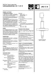
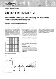
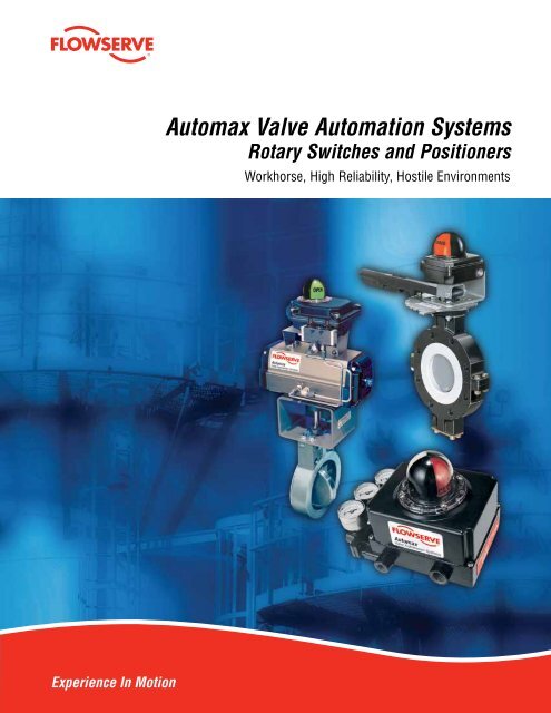
<strong>Automax</strong> <strong>Valve</strong> <strong>Automation</strong> <strong>Systems</strong><br />
Rotary Switches and Positioners<br />
Workhorse, High Reliability, Hostile Environments
2<br />
<strong>Flowserve</strong> Flow Control <strong>Automax</strong> Switches and Positioners<br />
<strong>Flowserve</strong> <strong>Corporation</strong>’s <strong>Automax</strong> <strong>Valve</strong> <strong>Automation</strong><br />
<strong>Systems</strong> provides complete valve and damper automation<br />
to the worldwide processing industries. We provide<br />
maximum value to the end user through a broad<br />
offering of products, services, application engineering<br />
and our systematic approach to automation.<br />
Featured Products<br />
UltraSwitch GL/PL/XCL Series Rotary Position Indicators<br />
The UltraSwitch series of position indicators provides a compact and economical<br />
package for both visual and remote electrical indication of valve position.<br />
Models are available in both die cast aluminum and engineered resin versions<br />
with UL, CSA and ATEX ratings suitable for Class I Division 1,2 and Zone 0, 1, 2<br />
applications.<br />
Aviator II/BUSwitch Integrated <strong>Valve</strong> Controller<br />
With Internal Pilot Solenoid<br />
The Aviator Integrated <strong>Valve</strong> Controller with internal pilot solenoid coil provides<br />
a truly integrated package for both visual and electrical position indication<br />
as well as control of supply air to rotary actuators. The <strong>Automax</strong> BUSwitch<br />
provides all of the features of the Aviator but enables control and monitoring of<br />
automated on-off valves through digital fieldbus technology.<br />
Quality, Dependability and Productivity<br />
Recognized as the leaders in position indication and<br />
positioning control, <strong>Automax</strong> limit switch and positioner<br />
products provide unparalleled performance combined with<br />
ease of calibration and maintenance.<br />
<strong>Automax</strong> rotary position indicators and positioners have<br />
a proven track record in industries such as chemical and<br />
petrochemical processing, oil and gas, pulp and paper,<br />
pharmaceutical, and energy-related industries. Hazardous<br />
location approvals and corrosion resistant materials make<br />
the <strong>Automax</strong> rotary position indicators and positioners ideal<br />
for even the most hostile environments.<br />
Our ISO 9001 certified manufacturing facilities, R&D<br />
department and engineering headquarters are located in<br />
Springville, Utah; Cookeville, Tennessee and Solna, Sweden.<br />
Sales and service facilities are strategically located in<br />
industrial centers throughout the world.<br />
Page 4-6<br />
Page 8, 10
Switch Options<br />
An extensive range of both mechanical and proximity limit switches<br />
makes the UltraSwitch and Aviator the perfect choices for a wide range<br />
of applications.<br />
AutoBrakits<br />
Stainless steel NAMUR mounting kits provide consistent and reliable<br />
direct coupling to NAMUR compliant actuators.<br />
Apex 7000 Modular Positioner<br />
Available in die-cast aluminum, the Apex positioner combines precise<br />
valve positioning with advanced features. Standard features include noninteractive<br />
zero/span and modular options such as 3-15 psi or 4-20 mA<br />
control signal, visual indication and top-mount limit switch feedback.<br />
Apex 8000 High Performance Positioner<br />
A two-stage pneumatic relay gives the Apex 8000 outstanding dynamic<br />
response combined with precise throttling control. Features include<br />
adjustable gain, noninteractive zero/span, and modular options such as<br />
3-15 psi or 4-20 mA control signal, visual indication and internal or topmount<br />
limit switch feedback.<br />
Logix Digital Positioner<br />
The Logix positioner provides highly accurate positioning and<br />
outstanding dynamic response through advanced digital feedback and<br />
control. Two housings are available for general purpose, nonincendive,<br />
intrinsically safe, or explosionproof applications. Models are available<br />
in 4-20 mA analog input, Foundation Fieldbus, or the industry standard<br />
HART protocol.<br />
Page 9<br />
Page 9<br />
Page 12-15<br />
Page 16-17<br />
Page 19-21<br />
flowserve.com<br />
3
4<br />
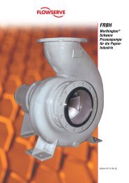
GL-Series UltraSwitch Position Indicators<br />
The GL-Series rotary limit switch enclosure provides<br />
a compact economical package for visual and remote<br />
electrical indication of valve position. The die cast<br />
aluminum housing is electrostatic powder coated and<br />
designed to meet NEMA 4x standards. The housing can<br />
also be configured for sanitary applications.<br />
How To Order (Select Bold Type Code from each column that applies)<br />
Optional Prefix Model Cover Switch*<br />
Blank - Double D Shaft<br />
(1/4” Flats)<br />
N - NAMUR Shaft<br />
E - Epoxy Coated<br />
B - Epoxy Coating/<br />
NAMUR shaft<br />
H - Hex Head Cover<br />
Screws<br />
D - Hex Head Cover<br />
Screws/NAMUR<br />
Shaft<br />
Terminal Strip is multipoint<br />
and prewired.<br />
Dual 1/2” conduit entries are<br />
standard; optional third entry is<br />
available<br />
Housing is die cast<br />
aluminum with internal and<br />
external electrostatic powder<br />
coating, designed to meet<br />
NEMA 4x standards.<br />
GL 1 - Flat Top<br />
2 - Pharos Indicator<br />
C - Pharos 90° 3-way<br />
D - Pharos 180° 3-way<br />
E - Pharos 180° 3-way<br />
Center Blocked<br />
T - Flat Indicator<br />
Note: Example: GL210, NGL130T<br />
I option valid for Type 4, 8, E, G and T switch types.<br />
For replacement Pharos kit part numbers, see UltraSwitch nomenclature<br />
* Consult factory for additional switch options<br />
** 2 SPST or 2 SPDT only. Maximum of 8 Terminals.<br />
Features:<br />
• Pharos visual indicator for high contrast,<br />
wide-angle viewing of valve position.<br />
• NAMUR mounting compliance<br />
eliminates coupler and<br />
maximizes interchangeability.<br />
• Captive stainless steel cover<br />
screws.<br />
• Sanitary options include captive<br />
stainless steel hex head cover screws.<br />
Standard housing offers a no “nooks and crannies” design to<br />
facilitate washdown.<br />
0 - No Switches (Empty Housing)<br />
1 - (2) SPDT Mechanical<br />
3 - (2) DPDT Mechanical<br />
4 - (2) SPST Proximity<br />
5 - (2) SPDT Proximity<br />
8 - (2) P&F NJ2-V3-N (NAMUR)<br />
D - DeviceNet Communication Card<br />
E - (2) SPDT Sabre Proximity<br />
G - (2) SPDT Mechanical Gold Contacts<br />
P - (2) Phazer II SPDT Proximity<br />
T - (2) Phazer II BRS SPST Proximity<br />
Z - AS-i Communications Card<br />
Switches are available in<br />
a wide range of options.<br />
Solenoid<br />
Options<br />
Options<br />
0 - No Solenoid Blank - No Option<br />
T - Third Conduit<br />
Entry<br />
H - Heavy-Duty**<br />
Terminal Block<br />
I - F.M. Intrinsically<br />
Safe Class I, II,<br />
III Div I Groups<br />
A-G (see notes)<br />
Quick-Set spring loaded<br />
cams are extra wide and<br />
splined to allow tool-free<br />
limit switch calibration.<br />
Extra Terminal<br />
Locations<br />
Blank - 2 Open<br />
Terminal<br />
Locations<br />
(Standard)<br />
4 - 4 Open Terminal<br />
Locations (2 SPST<br />
Switches)<br />
6 - 6 Open Terminal<br />
Locations (2 SPDT<br />
Switches)<br />
8 - 8 Open Terminal<br />
Locations (2 SPST<br />
Switches)
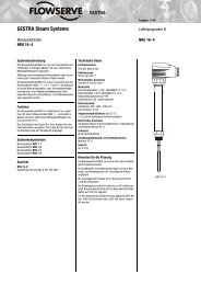
PL-Series UltraSwitch Position Indicators<br />
The PL-Series UltraSwitch is provided with an engineered<br />
resin enclosure making it ideal for harsh corrosive<br />
environments. It is certified to UL/CSA/ATEX standards<br />
for nonincendive Class 1, Div. 2 hazardous locations.<br />
Designed to meet NEMA 4, 4x standards, the housing<br />
features a unique labyrinth cover seal.<br />
How To Order (Select Bold Type Code from each column that applies)<br />
Optional Prefix Model Cover Switch* Analog Output<br />
Blank - Double D<br />
Shaft (1/4”<br />
Flats)<br />
N - NAMUR Shaft<br />
H - Hex Head Cover<br />
Screws<br />
D - Hex Head<br />
Cover Screws/<br />
NAMUR Shaft<br />
PL - Zytel ®<br />
Engineered<br />
Resin<br />
Housing,<br />
NEMA 4, 4x<br />
1 - Flat Cover<br />
U - UltraDome<br />
Indicator<br />
C - 90° 3-way<br />
D - 180° 3-way<br />
E - 180° 3-way<br />
Center<br />
Blocked<br />
*Consult factory for additional switch options.<br />
Zytel ® is a registered trademark of DuPont.<br />
Note: I option valid for Type 4, 8, E, G and T switch types<br />
** 2 SPST or 2 SPDT only. Maximum of 8 Terminals.<br />
0 - No Switches (Empty<br />
Housing)<br />
1 - (2) SPDT Mechanical<br />
2 - (4) SPDT Mechanical<br />
A - (2) SPDT Mechanical with<br />
3-Position Control<br />
D - DeviceNet Communication<br />
Card<br />
G - (2) SPDT Mechanical, Gold<br />
Contacts<br />
3 - (2) DPDT Mechanical<br />
4 - (2) SPST Proximity<br />
5 - (2) SPDT Proximity<br />
6 - (4) SPST Proximity<br />
E - (2) Sabre SPDT Proximity<br />
F - (4) Sabre SPDT Proximity<br />
P - (2) Phazer II SPDT<br />
Proximity<br />
H - (4) Phazer II SPDT<br />
Proximity<br />
T - (2) Phazer II BRS SPDT<br />
Proximity<br />
W - (4) Phazer II BRS SPDT<br />
Proximity<br />
8 - (2) P&F NJ2-V3-N (NAMUR)<br />
U - (2) GO Proximity,<br />
35-13319-A1A<br />
Z - AS-i Communications Card<br />
flowserve.com<br />
Features:<br />
• UltraDome visual indicator provides high contrast, wide-angle<br />
viewing of valve position.<br />
• Quick-Set spring loaded cams are extra wide and splined to<br />
allow tool-free limit switch calibration.<br />
• Switches available in a wide range of options.<br />
• Terminal Strip is multipoint and prewired.<br />
• Housing is an engineered resin suitable for corrosive<br />
environments.<br />
• Dual 3/4” conduit entries are standard.<br />
• NAMUR mounting compliance eliminates coupling and<br />
maximizes interchangeability.<br />
• Captive stainless steel cover screws.<br />
• Internal Potting Wells within housing at the conduit entries<br />
available for factory sealed leads. They may be filled with<br />
conduit potting compound or RTV silicone sealant to prevent<br />
the ingress of corrosive vapors or liquids.<br />
0 - None<br />
T - 4-20 mA<br />
Transmitter<br />
D - 180° Travel<br />
4-20 mA<br />
Transmitter<br />
E - 45°/60° Travel<br />
4-20 mA<br />
Transmitter<br />
A - 0-1k Ohm<br />
Potentiometer<br />
B - 0-5k Ohm<br />
Potentiometer<br />
C - 0-10k Ohm<br />
Potentiometer<br />
Solenoid<br />
Options<br />
Options<br />
0 - None 0 - No Option<br />
H - Heavy-Duty<br />
Terminal<br />
Block**<br />
P - Seal/Potted<br />
Leads<br />
I - FM/CSA<br />
Intrinsically Safe<br />
Class I, II, III<br />
Div 1, A-G (See<br />
Notes)<br />
Extra Terminal<br />
Locations<br />
Blank -<br />
2 Open Terminal<br />
Locations<br />
(Standard)<br />
4 - 4 Open Terminal<br />
Locations (2 SPST<br />
switches)<br />
6 - 6 Open Terminal<br />
Locations (2 SPDT<br />
switches)<br />
8 - 8 Open Terminal<br />
Locations (2 or 4<br />
SPST switches)<br />
5
6<br />
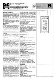
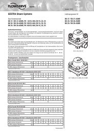
XCL-Series UltraSwitch Position Indicators<br />
The XCL-Series UltraSwitch is a globally-certified explosionproof/flameproof position indicator for use throughout<br />
the world. The rugged die cast aluminum enclosure has a dichromate undercoat and electrostatic polyester powder<br />
topcoat for superior corrosion resistance. The housing is certified to UL/CSA/ATEX standards and is available with<br />
optional position transmitter and a wide range of switches.<br />
Features:<br />
• UltraDome visual indicator provides high contrast, wide-angle viewing of valve<br />
position.<br />
• Quick-Set spring loaded cams are extra wide and splined to allow tool-free<br />
limit switch calibration.<br />
• Switches available in a wide range of options.<br />
• Terminal Strip is multipoint and prewired.<br />
• Housing is die cast aluminum with dichromate undercoat and electrostatic<br />
powder topcoat, UL/CSA/ATEX approved for hazardous locations.<br />
• Dual 3/4” conduit entries are standard.<br />
• NAMUR mounting compliance eliminates coupling and maximizes<br />
interchangeability.<br />
• Captive stainless steel cover screws.<br />
• Potting compartments available for factory sealed leads.<br />
How To Order (Select Bold Type Code from each column that applies)<br />
Shaft Option Model Indicator Option No. Switches Switch Type*<br />
D - Double D<br />
Shaft (1/4”<br />
Flats)<br />
N - NAMUR Shaft<br />
XCL - (2) 3/4”<br />
NPT<br />
Conduit<br />
XML - (2) M25<br />
Conduit<br />
1 - Flat Top (no indicator)<br />
U - Red/Green (std)<br />
C - 90° 3-way<br />
D - 180° 3-way<br />
E - 180° 3-way Blocked Center<br />
K - Ektar Red/Green<br />
H - Black/Yellow<br />
R - Reverse (Red = Open, Green = Closed)<br />
3 - Four window Ultradome<br />
F - 120° thru/divert Ultradome<br />
W - White = closed, Blue = open<br />
X - Three position Type 6 White = closed,<br />
Blue = open<br />
0 - No<br />
Switches<br />
1 - 1 Switch<br />
2 - 2 Switches<br />
4 - 4 Switches<br />
00 - No Switches<br />
M1 - SPDT Mechanical<br />
MC - SPDT Mechanical - Construction<br />
for 250°F<br />
MG - SPDT Mechanical - Gold Plated<br />
M3 - DPDT Mechanical<br />
MB - DPDT Mechanical - Licon<br />
MA - 3-Position Control<br />
MD - DA 3-Position Control w/Indication<br />
MS - SR 3-Position Control w/Indication<br />
P4 - SPST Proximity<br />
P5 - SPDT Proximity<br />
PE - SPDT Sabre<br />
PP - SPDT Phazer II<br />
Certifications Analog Output Options Wiring Options<br />
- 14 - General Purpose<br />
- 17 - UL/CSA CI.I,Div.I,Gr.CD/CI.1,Div.2 Gr.A-D / CL II Div.1, 2 GR E,F,G/CL III<br />
- 18 - UL/CSA/ATEX Explosionproof<br />
- 19 - ATEX Explosionproof<br />
- 25 - IECEx Ex d IIB T5, Ex tD A21 IP 65<br />
- 26 - InMetro BR Ex d IIB T5<br />
- 27 - Factory Mutual/CUS Intrinsically Safe CI I,II,III Div. 1,2 GR A-G T5**<br />
- M1 - Metal Nameplate UL/CSA/ATEX Explosionproof (Mechanical Switch)<br />
- M2 - Metal Nameplate UL/CSA/ATEX Explosionproof (Proximity Switch)<br />
- M3 - Metal Nameplate ATEX Explosionproof<br />
- 0 - None (std)<br />
- T - 4-20 mA Transmitter<br />
- D - 180° 4-20 mA Transmitter<br />
- A - 0-1k Ohm Potentiometer<br />
- B - 0-5k Ohm Potentiometer<br />
- C - 0-10k Ohm Potentiometer<br />
Open Terminals (Minimum) Special Options Coating Options<br />
2 - 2 open (std)<br />
4 - 4 open Terminal Locations (2 SPST Switches)<br />
6 - 6 open Terminal Locations (2 SPDT Switches)<br />
8 - 8 open Terminal Locations (2 or 4 SPST Switches)<br />
0 - None (std)<br />
P - 180° Potentiometer Gearing<br />
V - Viton O-rings<br />
L - Lubricated cover bolts<br />
N - No silicone<br />
0 - None (std)<br />
H - Heavy-Duty Terminal Strip***<br />
1 - Brad Harrison 3 pin<br />
2 - Brad Harrison 5 pin<br />
3 - Brad Harrison 7 pin<br />
P - Sealed / Potted Leads<br />
0 - Black Polyester Powdercoat (std)<br />
E - White Epoxy<br />
W - White Epilon II<br />
Example<br />
NXCLU2M1-18-00200 = <strong>Automax</strong> XCL UltraSwitch, NAMUR Shaft, UltraDome indicator, (2) SPDT Mechanical switches, UL/CSA and ATEX certifications.<br />
*Consult factory for additional switch options.<br />
** -27 option valid for MG, P4, P5, PE, PT, and N8 switch options.<br />
***2 SPST or 2 SPDT only. Maximum of 8 Terminals.<br />
Optional 4-20 mA<br />
transmitter shown<br />
PL - SPDT Phazer II Proximity with LED<br />
PT - SPST Phazer II BRS Proximity<br />
PX - SPST Phazer II BRS Proximity with LED<br />
N8 - P+F NJ2-V3-N<br />
NQ - P&F NJ4-12GK-N (NAMUR)<br />
NR - P&F NJ4-12GM40-E1 (3-Wire NPN NO)<br />
NS - P&F NJ4-12GM40-E2 (3-Wire PNP NO)<br />
NT - P&F NJ4-12GK40-E2 (3-Wire PNP NO)<br />
NP - P&F SJ3.5-N (NAMUR)<br />
NU - GO Proximity 35-13319-A1<br />
SN - 3-Way Pneumatic <strong>Valve</strong>s<br />
FZ - AS-i Communications Card<br />
FD - DeviceNet Communications Card
3-Position Control <strong>Systems</strong><br />
<strong>Automax</strong> offers a wide range of solutions for dribble<br />
control or 3-position control applications. The Limit Switch<br />
Method utilizes a specially configured UltraSwitch with<br />
<strong>Automax</strong> solenoid valves to control the actuator through<br />
three distinct positions. The Positioner Method utilizes an<br />
Apex positioner with a special 3-position control circuit kit<br />
that permits a fail-safe operation of the actuator to the CW,<br />
Mid or CCW position on loss of air and/or electric. Options<br />
are available for feedback at all three positions.<br />
Limit Switch Method:<br />
• Dribble Control – primarily used with spring return actuators<br />
installed on 2-way valves, this system is generally used on<br />
tank-filling applications. The fully adjustable mid-position, or<br />
“dribble” position, permits the valve to stop short of closing<br />
to minimize spilling or overfilling. Based on the actuator’s fail<br />
direction, the package will fail CW or CCW on loss of air and/or<br />
electric.<br />
• 3-Position Control – used for 180° 3-way ball or plug valve<br />
applications where the actuator stops<br />
at 0°, 90° and 180° positions.<br />
The quick and simple calibration<br />
of the 90° mid-position was<br />
specifically developed<br />
for 3-way valve<br />
configurations<br />
utilizing 180°<br />
double acting<br />
actuators.<br />
Positioner Method:<br />
flowserve.com<br />
The most versatile system available, the Positioner Method<br />
can be used on dribble or 3-position control applications with<br />
90° spring return/double acting or 180° double acting actuators.<br />
Primarily utilized on double acting actuator packages,<br />
this method provides actuator failure to the CW, Mid or CCW<br />
positions on loss of electric and/or air supply (with <strong>Automax</strong><br />
Fail-Safe accumulator tank assembly).<br />
Features:<br />
• Integral Cam Assembly. Specially designed cams permit quick<br />
and easy mid-position calibration with pinpoint accuracy.<br />
• Feedback Options. 3-way visual indicator and electrical<br />
position feedback available for remote indication of the CW,<br />
Mid or CCW position.<br />
• Independent Feedback Circuits. Separate position indication<br />
loops permit alternate power source for feedback to PLC/DCS<br />
rather than voltage for solenoid valve control.<br />
• Mid-Position from CW/CCW. Unlike other systems available<br />
today, the mid-position can be reached from either direction.<br />
• Pre-wired UltraSwitch simplifies installation. The terminal<br />
strip features pre-wired jumpers and solenoid leads, permitting<br />
the operator to simply apply signal to the CW, Mid or CCW<br />
terminal locations.<br />
• AC or DC Circuits available.<br />
How To Order (Select Bold Type Code from each column that applies)<br />
Prefix Method Schematic Enclosure* Coil Classification Shaft Option Dome Option Coil Voltage<br />
3POS DA - Double<br />
Acting<br />
Actuator<br />
SR - Spring<br />
Return<br />
Actuator<br />
AC Circuits<br />
1 - DA Actuator w/o Electrical<br />
Position Indication (per sch.#<br />
807448-A)<br />
2 - SR Actuator w/o Electrical Position<br />
Indication (per sch.# 807451-A)<br />
3 - DA Actuator w/ Electrical Position<br />
Indication (per sch.# 807523-A)<br />
4 - SR Actuator w/ Electrical Position<br />
Indication (per sch.# 807524-A)<br />
DC Circuits<br />
5 - DA Actuator w/o Electrical Position<br />
Indication (per sch.# 807644-A)<br />
6 - SR Actuator w/o Electrical Position<br />
Indication (per sch.# 807645-A)<br />
7 - DA Actuator w/ Electrical Position<br />
Indication (per sch.# 807613-A)<br />
8 - SR Actuator w/ Electrical Position<br />
Indication (per sch.# 807622-A)<br />
*Consult factory for Positioner Method 3-Position Control <strong>Systems</strong>.<br />
X - XCL-Series<br />
UltraSwitch<br />
P - PL-Series<br />
UltraSwitch<br />
W - Weatherproof<br />
NEMA 4, 4x<br />
X - Explosionproof<br />
NEMA 4, 4x,<br />
7, 9<br />
N - NAMUR Shaft<br />
(std)<br />
S - Double-D Shaft<br />
(1/4” Flats)<br />
2 - Red/Green<br />
UltraDome<br />
C - 3-way 90°<br />
Indicator<br />
D - 3-way 180°<br />
Indicator<br />
E - 3-way 180°<br />
Blocked Center<br />
Indicator<br />
Example<br />
3POSDA3XWNE1 would have description and comments as<br />
follows:<br />
Double Acting Actuator<br />
DA Actuator w/ Position Indication (AC Circuit - per sch.#<br />
807523-A)<br />
XCL-Series UltraSwitch with Weatherproof NEMA 4, 4x<br />
Controls NAMUR Shaft<br />
3-way 180° Blocked Center Indicator<br />
110 VAC/50 Hz, 120 VAC/60 Hz Coils<br />
1 - 110 VAC/50 Hz,<br />
120 VAC/60 Hz<br />
2 - 220 VAC/50 Hz,<br />
240 VAC/60 Hz<br />
3 - 22 VAC/50 Hz,<br />
24 VAC/60 Hz<br />
4 - 24 VDC<br />
7
8<br />
Aviator II Integrated <strong>Valve</strong> Controller<br />
The Aviator XV-Series Integrated <strong>Valve</strong> Controller enclosure<br />
and solenoid valve provide an integrated package for<br />
position indication and control of supply air to rotary<br />
actuators. The XV-Series housing is globally certified<br />
explosion proof / flameproof with UL / CSA / ATEX / IECEx<br />
approvals for use throughout<br />
the world.<br />
Switches are<br />
available in a wide<br />
range of options.<br />
Quick-Set spring loaded<br />
cams are extra wide and<br />
splined to allow tool-free<br />
limit switch calibration.<br />
Corrosion Resistant Materials all exposed<br />
parts are either stainless steel, anodized<br />
aluminum, or aluminum treated with dichromate<br />
undercoat and polyester electrostatic powder<br />
top coat. The WR-Series provides further<br />
protection with an engineered resin enclosure.<br />
WR-Series<br />
The WR-Series offers many features of the XV-Series in an<br />
engineered resin housing. The housing made of engineered<br />
resin provides an excellent enclosure for harsh chemical environments<br />
and can be rated for nonincendive and intrinsicallysafe<br />
applications. In addition, dual internal solenoid coils are<br />
available in the WR-Series.<br />
Features<br />
• Captive stainless steel cover screws.<br />
• UltraDome visual position indicator provides high contrast,<br />
wide-angle viewing of valve position.<br />
• Fieldbus Upgradeability. The Aviator has been designed to<br />
accommodate the circuitry required to interface with various<br />
fieldbus protocols.<br />
• NAMUR mounting compliance eliminates coupler and<br />
maximizes interchangeability.<br />
Three 1/2” conduit entries<br />
are standard (XV-Series).<br />
Internal Pilot Solenoid Coil offers<br />
the advantage of having the solenoid<br />
coil contained and protected within<br />
the Aviator housing. This provides a<br />
high degree of protection in hazardous<br />
environments and washdown<br />
applications.
UltraSwitch/Aviator Internal Switch Options<br />
Mechanical Switches<br />
Proximity Switches<br />
hermetically sealed for<br />
long life.<br />
High Performance<br />
Proximity Switches<br />
hermetically sealed for severe<br />
service and long life.<br />
Many additional switch<br />
options are available.<br />
Consult factory for details.<br />
AutoBrakits<br />
Type 1 / M1<br />
(2) SPDT Mechanical<br />
15 amp @ 125 VAC,<br />
1/2 amp @ 125 VDC<br />
Minimum 50 mA<br />
Type 4 / R4<br />
(2) SPST Proximity<br />
0.35 amp @ 140 VAC,<br />
1 amp @ 50 VDC, 50 Watt Max.<br />
Minimum 1 mA<br />
Type E / P1 Sabre Switch<br />
(2) SPDT Proximity<br />
1 amp @ 120 VAC,<br />
1 amp @ 24 VDC, 25 Watt Max.<br />
Minimum 1 mA<br />
NAMUR mounting kits and NAMUR shaft options permit direct<br />
coupling of <strong>Automax</strong> limit switches or positioners to NAMUR<br />
actuators. Our NAMUR shaft options include an integral<br />
alignment pin to ensure accurate fit between accessory and<br />
actuator. The kits feature stainless steel construction at an<br />
economical price.<br />
Type G / MG<br />
(2) SPDT Mechanical<br />
Gold-Plated Contacts<br />
1 amp @ 125 VAC<br />
1 amp @ 24 VDC<br />
Minimum 1 mA<br />
Type 5<br />
(2) SPDT Proximity<br />
1/4 amp @ 120 VAC,<br />
1/4 amp @ 28 VDC, 3 Watt Max.<br />
Minimum 5 mA<br />
Type P / PP Phazer II<br />
(2) SPDT Proximity<br />
3 amp @ 120 VAC,<br />
2 amp @ 24 VDC, 100 Watt Max.<br />
Minimum 50 mA<br />
Type 3<br />
(2) DPDT Mechanical<br />
15 amp @ 125 VAC<br />
Minimum 50 mA<br />
Consult factory for DC voltages<br />
Type 8<br />
(2) Solid State Pepperl & Fuchs<br />
Proximity<br />
2-wire NAMUR per<br />
DIN 19234<br />
flowserve.com<br />
Type T / B4 BRS<br />
(2) SPST Proximity<br />
3 amp VAC,<br />
1/2 amp @ 24 VDC, 100 Watt Max.<br />
Minimum 1 mA<br />
9
10<br />
How To Order WR / FR Series Resin Aviator/ BUSwitch (Select Bold Type Code from each column that applies)<br />
Model Indicator Switch Number of Coils Solenoid Coil Spool <strong>Valve</strong><br />
WR - Resin NEMA<br />
4, 4x<br />
FR - Resin I.S.<br />
Class 1, Div. 1<br />
Groups A-D<br />
*see note<br />
for sensor<br />
availability.<br />
U - UltraDome<br />
Indicator<br />
C - 90° 3-way<br />
D - 180° 3-way<br />
E - 180° 3-way<br />
Center<br />
Blocked<br />
M1 - (2) SPDT Mechanical<br />
MG - (2) SPDT Mechanical<br />
Gold Contacts<br />
R4 - (2) SPST Proximity<br />
P1 - (2) Sabre SPDT<br />
Proximity<br />
PP - (2) Phazer II SPDT<br />
Proximity<br />
B4 - (2) BRS SPST<br />
Proximity<br />
S4 - (2) P&F NJ2-V3-N<br />
(NAMUR)<br />
SE - (2) Efector Type<br />
IN-2002-ABOA<br />
Communication Protocol<br />
F2 - 2-wire Foundation<br />
Fieldbus<br />
F4 - 4-wire Foundation<br />
Fieldbus<br />
FA - AS-i<br />
FN - DeviceNet<br />
0 - Single Coil<br />
1 - Dual Coil<br />
2 - External<br />
Solenoid Coil<br />
(BUSwitch<br />
only F4<br />
option)<br />
A - 110 VAC 50/60 Hz<br />
C - 220 VAC 50/60 Hz<br />
F - 12 VDC<br />
G - 24 VDC<br />
H - 12 VDC Low<br />
Power<br />
J - 24 VDC Low<br />
Power<br />
K - 24 VDC<br />
Intrinsically Safe<br />
BUSwitch Only<br />
G - 24 VDC<br />
J - 24 VDC Low<br />
Power<br />
P - 24 VDC Piezo<br />
Ultra-Low Power<br />
(F2 Protocol only)<br />
O - None (F4 option<br />
only)<br />
Note: IS approval valid for Aviator with Type MG, R4, B4 and S4 with “K” coil. Also valid for BUSwitch F2 option and “P” coil.<br />
1 - 3-way<br />
Aluminum<br />
2 - 3-way<br />
Stainless<br />
Steel<br />
3 - 4-way<br />
Aluminum<br />
4 - 4-way<br />
Stainless<br />
Steel<br />
Shafts and<br />
Coatings<br />
N - NAMUR<br />
Shaft<br />
Spool <strong>Valve</strong> Options<br />
R - Thermoplastic Rain<br />
Caps (Standard)<br />
M - Thermoplastic Rain<br />
Caps/Momentary<br />
Manual Override<br />
L - Thermoplastic Rain<br />
Caps/Locking Manual<br />
Override<br />
X - Sintered Bronze Exhaust<br />
Mufflers<br />
Y - Sintered Bronze Exhaust<br />
Mufflers/Momentary<br />
Manual Override<br />
Z - Sintered Bronze Exhaust<br />
Mufflers/Locking<br />
Manual Override<br />
S - Stainless Steel Exhaust<br />
Mufflers<br />
T - Stainless Steel Exhaust<br />
Mufflers/Momentary<br />
Manual Override<br />
U - Stainless Steel Exhaust<br />
Mufflers/Locking<br />
Manual Override<br />
How To Order Aviator II Discrete <strong>Valve</strong> Contoller (Select Bold Type Code from each column that applies)<br />
Shaft Type Model Indicator Option No. Switches Switch Type*<br />
D - Double D XV - Aluminum U - Standard UltraDome (Red/Green) 0 - 0 Switch Elements<br />
M1 - SPDT Mechanical<br />
Shaft (1/4”<br />
Flats)<br />
N - NAMUR VDI<br />
/ VDE 3845<br />
Shaft<br />
Housing,<br />
Explosionproof<br />
/<br />
Flame-proof,<br />
(2) 3/4” NPT<br />
Conduit<br />
3 - 4-Window UltraDome<br />
C - 90° 3-way UltraDome<br />
D - 180° 3-way UltraDome<br />
E - 180° 3-way Blocked Center UltraDome<br />
F - 120° thru/divert UltraDome<br />
1 - 1 Switch Element<br />
2 - 2 Switch Elements<br />
3 - 3 Switch Elements<br />
4 - 4 Switch Elements<br />
MG - SPDT Mechanical - Gold Plated<br />
MB - DPDT Mechanical - Licon<br />
P4 - SPST Proximity<br />
PE - Sabre SPDT Proximity<br />
PP - Phazer SPDT Proximity<br />
XM - Aluminum<br />
Housing,<br />
Explosion-<br />
H - Black Yellow UltraDome<br />
K - Ektar UltraDome (Red/Green)<br />
PL - Phazer SPDT Proximity with LED<br />
PT - BRS SPDT Proximity<br />
proof / R - Reverse UltraDome (Red = Open, Green<br />
PX - BRS SPDT Proximity with LED<br />
Flame-proof,<br />
(2) M20<br />
Conduit<br />
= Closed)<br />
W - White/Blue UltraDome<br />
X - 180° 3-Way UltraDome (White/Blue)<br />
N8 - P+F NJ2-V3-N / NJ2-V3-N-V5 (NAMUR)<br />
NP - P+F SJ3.5N (NAMUR)<br />
FA - AS-i<br />
F2 - FOUNDATION Fieldbus-2-Wire<br />
F4 - FOUNDATION Fieldbus-4-Wire<br />
FN - DeviceNet<br />
Certifications Number of Coils Solenoid Coil Voltage Spool <strong>Valve</strong><br />
- 14 - General Purpose<br />
- 17 - CSA CI.I,Div.I,Gr.CD T6/CI.1,Div.2 Gr.ABCD T3C/ CL II<br />
Div.1 GR E,F,G<br />
- Div.2 GR E,F,G, CL III T6, CL I, Zone 1 Aex-d IIB T3/T4<br />
- CL I Zone 1 Ex-d IIB T3/T4<br />
- 19 - ATEX II 2 G EEx d IIB T5<br />
- 24 - CSA CI.I,Div.I,Gr.CD / CL II Div.1 GR E,F,G, Div.2 GR E,F,G /<br />
CL III T6<br />
- CL I, Zone 1 Aex-d IIB T3/T4 / CL I Zone 1 Ex-d IIB T3/T4<br />
- 25 - IECEx Exd IIB T3/T4 IP65<br />
- 27 - cFMus CI I,II,III Div 1 GR ABCDEFG T5 *see for sensor<br />
availability.<br />
- 0 - Integral Single<br />
Coil<br />
- 1 - External<br />
Solenoid Coil<br />
(F4 option<br />
only)<br />
- 0 - None (F4 option only)<br />
- A - 110VAC/50Hz, 120VAC/60Hz (2-Watt)<br />
- C - 220VAC/50Hz, 240VAC/60Hz (2-Watt)<br />
- F - 12VDC (2-Watt)<br />
- G - 24VDC (2-Watt)<br />
- H - 12VDC Low-Power (.67 Watt)<br />
- J - 24VDC Low-Power (.67 Watt)<br />
- K - 24VDC Intrinsically Safe<br />
- P - 24VDC Ultra Low-Power (Piezo.006<br />
Watt) (F2 option only)<br />
000 - None<br />
3A2 - 3-Way Aluminum - 1.8 Cv<br />
3S2 - 3-Way Stainless Steel - 1.8 Cv<br />
3A4 - 3-Way Aluminum - 4.5 Cv<br />
3S2 - 3-Way Stainless Steel - 4.5 Cv<br />
4A2 - 4-Way Aluminum - 1.8 Cv<br />
4S2 - 4-Way Stainless Steel - 1.8 Cv<br />
4A4 - 4-Way Aluminum - 4.5 Cv<br />
4S4 - 4-Way Stainless Steel - 4.5 Cv<br />
Coating Options Spool <strong>Valve</strong> Exhaust Mufflers Override Options Other Options<br />
P - Polyester Powder Coating (std) R - Thermoplastic Rain Caps (Standard) N - No Override (Standard)<br />
1 - Silicone Free Aviator (Magnalube Grease<br />
E - White Epoxy Coating<br />
B - Sintered Bronze Exhaust Mufflers M - Momentary Manual Override<br />
or Equivalent)<br />
S - Stainless Steel Exhaust Mufflers<br />
L - Locking Manual Override<br />
E - Wiedmuller Terminal (European Style)<br />
P - High Temp Phenolic<br />
L - Low Temp Spool<br />
*IS approval valid for: MG, P4, PE, PT, N8, and NP sensors with K coil. Also valid for F2 option & “P” coil.
BUSwitch Integrated <strong>Valve</strong> Controller<br />
The BUSwitch Integrated <strong>Valve</strong> Controller provides all<br />
of the features of the Aviator but enables control and<br />
monitoring of automated on-off valves through fieldbus<br />
technology. The BUSwitch communication cards provide a<br />
gateway to fieldbus networks allowing seamless<br />
integration of the limit switches and solenoid valves. The<br />
integral BUSwitch functions assist the user with predictive<br />
and preventative maintenance. The intelligent valve<br />
automation package features AS-i, Foundation Fieldbus<br />
and DeviceNet protocols. The BUSwitch is available in<br />
both explosionproof aluminum or corrosion resistant<br />
engineered resin housings.<br />
Protocol-Specific Features:<br />
• FOUNDATION Fieldbus BUSwitch controls include cycle counter<br />
and timer functions. User-selectable failure modes permit<br />
valves to move to desired position on loss of communications.<br />
Dry-contact external input enables integration of emissiondetecting<br />
pressure switch or other simple device.<br />
AS-i<br />
• GL, PL and XCL-Series UltraSwitch (requires external 24 VDC<br />
solenoid valve)<br />
• WR and XV-Series BUSwitch with integral coil and spool valve<br />
• Centura CE-Series electric actuator (independent circuit permits<br />
use of any motor voltage option)<br />
DeviceNet<br />
• GL, PL and XCL-Series UltraSwitch (requires external 24 VDC<br />
solenoid valve)<br />
• WR and XV-Series BUSwitch with integral coil and spool valve<br />
FOUNDATION Fieldbus<br />
• WR, FR and XV-Series BUSwitch with integral coil and spool<br />
valve<br />
• Centura CE-Series electric actuator (24 VDC motor only)<br />
• Logix 3400IQ/MD series digital positioner<br />
HART<br />
• Logix 520si/MD digital positioner<br />
• Logix 3200IQ/MD series digital positioner<br />
Max. No.<br />
of Devices/<br />
Segment<br />
Max. Cable<br />
Length (ft)<br />
Data Speed<br />
(kbps)<br />
flowserve.com<br />
• DeviceNet BUSwitch offers basic on-off valve control with<br />
limited diagnostic capabilities. Solenoid coil continuity, stroke<br />
timer, and stroke counter provide important information for<br />
effective valve and actuator maintenance. A dry-contact external<br />
input enables integration of emission-detecting pressure switch<br />
or other simple device.<br />
• AS-i BUSwitch provides simple on-off valve control in a<br />
very economical package. It is available in all limit switch<br />
enclosures, including the GL, PL and XCL UltraSwitches.<br />
AS-i Foundation Fieldbus DeviceNet<br />
63 32 64<br />
328 2953 328<br />
167 31.25 125 to 500<br />
11
<strong>Flowserve</strong> Flow Control <strong>Automax</strong> Positioners<br />
<strong>Flowserve</strong> is a leader in the integration of microprocessor<br />
technology and digital communications into<br />
control valve and quarter-turn actuation products.<br />
Whether you are looking to interface with the latest<br />
fieldbus protocol or for the highest performance digital<br />
technology, <strong>Flowserve</strong> can answer your needs.<br />
The <strong>Automax</strong> family of positioners provides a full line for<br />
your control valve requirements, from basic analog positioners<br />
to high performance digital positioners. All analog<br />
positioners are offered in pneumatic or electro-pneumatic<br />
versions. Digital positioners are available for HART or<br />
Foundation Fieldbus communication protocols. Positioners<br />
are available with global certifications including FM, CSA,<br />
SAA and ATEX approvals.<br />
12<br />
Apex 7000<br />
High performance, modular analog positioner with advanced<br />
features.<br />
Apex 8000<br />
Top of the line analog positioner with advanced features.<br />
Logix 500si<br />
Full-featured, high performance, digital positioner for general<br />
purpose, nonincendive and intrinsically safe applications.<br />
Logix 3200IQ<br />
Full-featured, top of the line performance, digital positioner<br />
with explosionproof enclosure.
Apex 7000 Series<br />
Apex 7000 Series<br />
The Apex 7000 Series Positioner provides accurate valve<br />
positioning with advanced features. It may be used with<br />
3-15 psi pneumatic control signals, or fitted with an<br />
optional current-to-pressure transducer for 4-20 mA signal<br />
input. The Apex is available with many options including:<br />
top-mount limit switches, position feedback transmitter,<br />
speed controls, and our UltraDome Visual Position<br />
Indicator.<br />
Features<br />
• NAMUR mounting compliance eliminates coupler and<br />
maximizes interchangeability.<br />
• Captive Cover Screws permit calibration while minimizing the<br />
potential for lost screws.<br />
• Optional UltraDome Visual Position Indicator provides high<br />
contrast, wide-angle viewing of valve position.<br />
• Vibration Resistant. Low spool mass, outboard spool bearings,<br />
and locking calibration adjustments provide reliable operation<br />
under high vibration.<br />
• Field Upgradeable. The Apex is field upgradeable to various<br />
electro-pneumatic options. Switches and/or a position<br />
transmitter are field installable via top-mount UltraSwitches.<br />
Housing is die cast aluminum<br />
with electro-deposited epoxy<br />
paint or with optional TUFRAM<br />
R-66 coating.<br />
Apex 7000<br />
Pneumatic Positioner<br />
APEX 7000<br />
Spool <strong>Valve</strong>s available<br />
in low flow and high<br />
flow versions to match<br />
actuator valve/load<br />
requirements.<br />
Non-interactive Span<br />
adjustment<br />
flowserve.com<br />
13
14<br />
Apex 7000 Series (Metallic)<br />
How To Order (Select Bold Type Code from each column that applies)<br />
Model Indicator Gauges Spool <strong>Valve</strong>s Cam Type<br />
70 - PP Input 3-15 psi<br />
71 - EP Input 4-20 mA<br />
General Purpose1 72 - EP Input 4-20<br />
mA FM/CSA/<br />
ATEX/IECEx<br />
Explosionproof2 73 - EP Input 4-20<br />
mA FM/CSA/<br />
ATEX/IECEx<br />
Explosionproof3 74 - EP Input 4-20 mA<br />
FM/CSA/ATEX/IEC<br />
Intrinsically Safe4 75 - EP Input 4-20 mA<br />
Signal Loss Fail-in-<br />
Place1 76 - PP Input 6-30 psi<br />
Electro-pneumatic Positioner<br />
Apex 7200 shown with explosionproof<br />
I/P housing<br />
1 - Standard Flat with<br />
Green Indicator<br />
2 - UltraDome<br />
Indicator<br />
3 - No Gauges<br />
4 - Standard Gauges<br />
(SST casing w/<br />
brass internals)<br />
5 - Stainless Steel<br />
Gauges<br />
6 - Low Flow Spool<br />
<strong>Valve</strong><br />
7 - High Flow Spool<br />
<strong>Valve</strong><br />
A - Standard Linear<br />
Cam 3-15 psi, 3-9<br />
psi, 9-15 psi, D or<br />
R, 180 Degree<br />
B - 30 or 60 Degree<br />
Linear Cam D<br />
or R<br />
C - Characterized<br />
Cam, Squared,<br />
Square Root,<br />
D or R<br />
**Feedback options are not rated for hazardous locations. Use top-mounted UltraSwitch if hazardous location approvals are required.<br />
Note: 1 NEMA Type 4/4x<br />
2 FM/CSA NEMA (North America)<br />
Explosionproof CI.I, II, III, Div. 1, Gr. BCDEFG<br />
Flameproof II 2G, EExd IIB+H 2<br />
Feedback<br />
Options**<br />
O - None<br />
T - Top-Mounted<br />
UltraSwitch<br />
Cover<br />
3 FM/CSA Explosionproof Cl. I, II, III, Div. 1, Gr. BCDEFG<br />
Flameproofe EExd IIC<br />
4 FM/CSA Intrinsically Safe Cl.I, Div. 1 ABCD, ATEX II 2GD<br />
Ex ia IIC<br />
Electro-pneumatic Positioner<br />
Apex 7100 shown with weatherproof<br />
I/P housing and UltraDome indicator<br />
Options<br />
R - NAMUR Shaft - Tufram<br />
R-66 Severe Service<br />
Coating<br />
T - NAMUR Shaft - Standard<br />
Epoxy Coating<br />
Q - NAMUR Shaft - Silicone<br />
Seals for -40 0 to 1850 F<br />
D - Double “D” Shaft -<br />
Standard Epoxy Coating<br />
U - Double “D” Shaft - Turfram<br />
R-66 Severe Service<br />
Coating<br />
V - Double “D” Shaft - Silicone<br />
Seals for -40 0 1850 F
Apex 8000 High Performance Positioner<br />
The <strong>Automax</strong> Apex 8000 positioner provides outstanding<br />
control for a wide range of valves and dampers. The twostage<br />
pneumatic relay provides fast, sensitive response<br />
characteristics to meet demanding control objectives. It<br />
may be used with 3-15 psi pneumatic control signals or<br />
fitted with an I/P transducer for 4-20 mA signals. The Apex<br />
8000 is available with many options including position<br />
feedback limit switches, 4-20 mA position feedback transmitter<br />
and our UltraDome Visual Position Indicator.<br />
Two-Stage Pneumatic Relay<br />
flowserve.com<br />
Features:<br />
• Two-Stage Pneumatic Relay provides fast, sensitive response<br />
characteristics for precise control of critical control valves and<br />
dampers.<br />
• Non-Interactive Span Adjustment reduces calibration time.<br />
• Adjustable Gain allows positioner sensitivity adjustment for a<br />
wide range of valve/actuator applications.<br />
• Corrosion Resistant Materials. All exposed parts are either<br />
stainless steel or polyester powder coated anodized aluminum<br />
to permit use in corrosive environments.<br />
• Optional UltraDome Visual Position Indicator provides<br />
adjustable, high-contrast, full-angle viewing of valve position.<br />
• Field Upgradeable. The Apex 8000 is field-upgradeable to a<br />
number of electro-pneumatic options without removing the<br />
cover. Limit switches or a 4-20 mA position transmitter may be<br />
installed with basic tools.<br />
• Vibration Resistant. High natural frequency and pneumatic<br />
dampening make the Apex 8000 unaffected by vibrations with<br />
accelerations up to 2 G’s and frequencies to 500 Hz.<br />
Adjustable Gain<br />
Non-Interactive Span<br />
15
16<br />
Apex 8000 High Performance Positioner<br />
Top-Mounted UltraSwitch<br />
For hazardous area transmitter<br />
and switch feedback applications<br />
Electro-Pneumatic Positioner Apex 8000<br />
Shown with explosionproof I/P housing<br />
How To Order (Select Bold Type Code from each column that applies)<br />
Model Indicator Gauges Temperature Cam Type Feedback Options* Output Shaft<br />
80 - PP Input 3-15 psi<br />
81 - EP Input 4-20 mA<br />
General Purpose 1<br />
82 - EP Input 4-20 mA<br />
ExP, IS 2<br />
83 - EP Input 4-20 mA ExP 3<br />
84 - EP Input 4-20 mA IS4 85 - EP Input 4-20 mA<br />
ExP, IS 5<br />
1 - Standard Flat with<br />
Green Indicator<br />
2 - UltraDome Indicator<br />
K - EKTAR UltraDome<br />
D - Top-mounted<br />
UltraSwitch cover<br />
(Double “D” Switch Box)<br />
T - Top-mounted<br />
UltraSwitch cover<br />
(NAMUR Switch<br />
Box)<br />
3 - No Gauges<br />
4 - Standard<br />
Gauges<br />
(SST casing<br />
w/ brass<br />
internals)<br />
5 - Stainless<br />
Steel Gauges<br />
6 - 2 Stage Pneumatic Relay-<br />
EPDM / -40 to +220 F (-40<br />
to 104c)<br />
7 - 2-Stage Pneumatic Relay -<br />
Standard -20F to 180F<br />
8 - 2-Stage Pneumatic Relay<br />
- Extend Temperature -40F<br />
to 180F<br />
9 - 2-Stage Pneumatic Relay -<br />
VITON / -20 to +350 F (-29<br />
to +121 C)<br />
A - Standard Linear<br />
Cam 3-15 psi, 3-9<br />
psi, 9-15 psi, D or<br />
R, 180 Degree<br />
C - Characterized Cam<br />
Square, D or R<br />
(Quick Opening)<br />
*Feedback options are not rated for hazardous locations. Use top-mounted UltraSwitch if hazardous location approvals are required.<br />
Note: 1 NEMA Type 4/4x<br />
2 FM/CSA NEMA (North America)<br />
Explosionproof Cl. I, Div. 1, Gr. BCD, Cl. II, Div. 1, Gr. EFG<br />
Intrinsically Safe Cl. I II, Div. 1, Gr. ABCDEFG<br />
Nonincendive CI. I, Div. 2, Gr. ABCD<br />
Limit Switch<br />
Options<br />
4-20 mA Transmitter Option<br />
Limit Switches<br />
3 ATEX Flameproof II 2GD Ex d IIB + H2 T6( -40 0 C to<br />
+400 C); tD A21 T40 0C 4 ATEX Intrinsically Safe II 1 G EEx ia IIC<br />
II 3 GD (T70 0 C) EEx nL IIC T6 (-40 0 C to +60 0 C)<br />
O - None<br />
F - 4-20 mA Transmitter<br />
K - (2) SPDT Mech.<br />
Switches<br />
M - (2) SPST Proximity<br />
Switches<br />
N - (2) SPDT Proximity<br />
Switches<br />
Q - (2) I.S. Rated Solid<br />
State Sensors<br />
Type K<br />
SPDT Mechanical<br />
10 amp 125 VAC<br />
5 amp 250 VAC<br />
1/2 amp 125 VDC<br />
1/4 amp 250 VDC<br />
Type M<br />
SPST Proximity<br />
1/4 amp 200 VDC<br />
1/2 amp 100 VDC<br />
1 amp 50 VDC<br />
0.35 amp 140 VAC<br />
Maximum Contact:<br />
50 Watt Resistive<br />
Type N<br />
SPDT Proximity<br />
1/4 amp @ 120 VAC<br />
1/4 amp @ 28 VDC<br />
Minimum 5 mA<br />
Type Q<br />
(2) Solid State Pepperl &<br />
Fuchs Proximity<br />
2-wire NAMUR per DIN<br />
19234<br />
Position Transmitter<br />
Position transmitter can be factory or field installed to provide a<br />
direct feedback from the positioner shaft. Leads are terminated<br />
within the electronic module.<br />
2-wire Current Output Signal<br />
Standard output signal: 4-20 mA 2-wire<br />
Power requirements: 6 to 30 VDC<br />
Output loading: 0 to 750 Ohms @ 24 VDC<br />
5 Australia ANZEX Flameproof<br />
Ex d IIB+H2 T6<br />
Intrinsically Safe Ex ia IIC T5 @650 C<br />
Ex n IIC T6<br />
T - NAMUR Shaft - Black<br />
Polyester Powder<br />
Coat, 1/2” NPT Conduit<br />
Entries<br />
D - Double “D” Shaft<br />
- Black Polyester<br />
Powder Coat, 1/2” NPT<br />
Conduit Entries<br />
U - NAMUR Shaft - Black<br />
Polyester Powder<br />
Coat, M20 Conduit<br />
Entries<br />
V - Double “D” Shaft<br />
- Black Polyester<br />
Powder Coat, M20<br />
Conduit Entries
Apex 8000 Modular Positioning System Options<br />
Apex 8000 Cam Features and Options<br />
The Standard Apex 8000 Cam (Designated by letter “A”)<br />
• Provides linear characterization<br />
• Allows 90 or 180 degree rotation<br />
• Accepts 3-15, 3-9 or 9-15 psi input<br />
• Is suitable for direct or reverse acting applications<br />
Optional cams are available for:<br />
• Squared or square root characterization<br />
Non-hazardous Location I/P<br />
• Input 4-20 mA<br />
• I/P Housing is corrosion resistant and<br />
weatherproof<br />
• Automatic supply pressure and ambient<br />
temperature compensation<br />
• Internal I/P filter regulator<br />
Hazardous Location I/P<br />
• Input 4-20 mA<br />
• I/P Housing NEMA 4x and 7 UL,<br />
C-UL, ATEX, SAA<br />
• Automatic supply pressure and<br />
ambient temperature compensation<br />
• Internal I/P filter regulator<br />
Limit Switches<br />
Type K SPDT Mechanical<br />
10 amp 125 VAC / 5 amp 250<br />
VAC<br />
1/2 amp 125 VDC / 1/4 amp 250<br />
VDC<br />
Limit Switch<br />
Type M SPST Proximity Option<br />
0.35 amp 140 VDC<br />
1 amp 50 VDC / 1/2 amp 100 VAC / 1/4 amp 200 VDC<br />
Max. Contact: 50 Watt Resistive<br />
Type N SPDT Proximity<br />
1/4 amp @ 120 VAC<br />
1/4 amp @ 28 VDC / Minimum 5 mA<br />
Type Q Switch<br />
(2) Solid State Pepperl & Fuchs<br />
Proximity 2-wire NAMUR per DIN 19234<br />
flowserve.com<br />
Position Transmitters<br />
Position Transmitters can be factory or field installed to provide<br />
a direct feedback from the positioner shaft. Leads are terminated<br />
within the electronic module.<br />
“UltraDome” or “Flat” Position Indicators<br />
17
18<br />
Logix Digital Positioners and Accessories<br />
Logix digital positioners offer <strong>Flowserve</strong><br />
customers the best in performance and<br />
features for their demanding applications.<br />
The Logix 500si is available in intrinsically<br />
safe, nonincendive or general purpose<br />
configurations for more competitive<br />
situations. The Logix 3200IQ is provided with<br />
an explosionproof enclosure and offers the<br />
highest level of performance and features.<br />
Logix 520SI/3200IQ Information Chart<br />
The following information is accessible from the Logix Digital <strong>Valve</strong> Controller:<br />
Identification<br />
Spool identification<br />
Air action<br />
Tag number<br />
Spring type<br />
<strong>Valve</strong> style<br />
<strong>Valve</strong> material<br />
<strong>Valve</strong> body size<br />
<strong>Valve</strong> serial number<br />
<strong>Valve</strong> manufacturer<br />
<strong>Valve</strong> pressure class<br />
<strong>Valve</strong> end connections<br />
Fail position<br />
Stroke length<br />
Flow direction<br />
Trim number/size<br />
Trim characteristic<br />
Stem/shaft diameter<br />
Trim type and material<br />
Leakage class<br />
Inlet/outlet pressure<br />
Actuator size and type<br />
Device name/description<br />
Embedded software version<br />
Electronic serial number<br />
Engineering units<br />
Message - up to 32 characters<br />
Calibration<br />
Stroke<br />
4-20 mA signal<br />
Pressure sensor<br />
Calibration date<br />
Calibrated by initials<br />
Data Acquisition<br />
<strong>Valve</strong> position<br />
4-20 mA signal<br />
Command signal<br />
Clockwise actuator pressure<br />
Counter clockwise actuator pressure<br />
Diagnostics and Signatures<br />
Step test<br />
Ramp test<br />
Internal power test<br />
Preventive Maintenance<br />
Actual travel<br />
Rated travel<br />
Travel alert<br />
Packing style<br />
Cycle counter<br />
Cycle alert<br />
Red denotes additional functionality available on model with advanced diagnostics.<br />
Logix Series 3200IQ Variables<br />
Noise filter<br />
Integral gain<br />
Board current<br />
Travel position<br />
Supply pressure<br />
Digital input signal<br />
Analog input signal<br />
Stroke open speed<br />
Stroke closed speed<br />
Internal temperature<br />
Position deviation alert<br />
Minimum position cutoff<br />
Communication error log<br />
Minimum proportional gain<br />
Maximum proportional gain<br />
Proportional gain multiplier<br />
Upper and lower travel alert<br />
Upper and lower soft limit stop<br />
Multiple characterization library<br />
Actuator pressure sensor check<br />
21-point custom characterization<br />
Two-level security (ValTalk)
Digital Positioners: <strong>Automax</strong> Logix 500si<br />
The Logix 500si digital positioner provides highly accurate<br />
positioning and very responsive control of quarter-turn<br />
valves and dampers. It combines state-of-the-art piezo<br />
valve technology with inner-loop feedback for precise<br />
control. The Logix 500si is available with North American<br />
or ATEX intrinsically safe and nonincendive approvals.<br />
The Logix 510si is available as a 4-20 mA I/P digital positioner.<br />
Utilizing industry standard HART protocol, the Logix 520si<br />
provides dual gain tuning, 21-point custom characterization<br />
and signatures for diagnostic purposes and accuracy measurements.<br />
It is available with limit switch or transmitter position<br />
feedback.<br />
Features:<br />
• Quick-Cal function provides fast, push-button automatic<br />
commissioning of positioner. The Direct User Interface allows<br />
local access to positioner control.<br />
• Two-Stage Control utilizes piezo technology combined with<br />
inner-loop feedback for precise control.<br />
• Using HART Protocol, the Logix 520si can use existing<br />
handheld communicators and supply extensive information.<br />
SoftTools software allows the operator to run diagnostics<br />
and signatures, calibrates, displays parameters, logs data,<br />
sets alarms, and performs other functions in a Windows<br />
environment with on-line help screens.<br />
• 21-Point Custom Characterization allows the valve to be in<br />
virtually any position the operator desires for a given input<br />
signal.<br />
flowserve.com<br />
• Local Status LED’s provide instant information relating to<br />
internal diagnostic codes, indicating 36 different conditions.<br />
These codes indicate positioner status and alarms without the<br />
need for a handheld communicator or laptop computer.<br />
• Jog Calibrate function allows users to easily calibrate the<br />
positioner on all actuators without travel stops.<br />
• AutoTune Function starts the self-calibration and auto tuning<br />
process to reduce commissioning time and ensure consistency<br />
between one valve and the next. A gain selector switch allows<br />
the user to increase or decrease the calculated gain for optimal<br />
performance.<br />
• NAMUR Interfaces, combined with compact and lightweight<br />
design, provide direct mounting to various rotary or linear<br />
actuators.<br />
How To Order (Select Bold Type Code from each column that applies)<br />
Model Diagnostics Certifications Paint Color Threaded Connections Feedback Shaft Operating Temperature<br />
51 - 4-20 mA<br />
Analog<br />
52 - HART<br />
4-20 mA<br />
0si - Standard<br />
Diagnostics<br />
-02 - Intrinsically-safe<br />
(FM/CSA) 1<br />
-14 - General Purpose<br />
-15 - Intrinsically-safe<br />
(ATEX) 2<br />
Language Visual Indicator Special Options<br />
E - English<br />
F - French<br />
G - German<br />
-F - Flat<br />
-D - Dome<br />
0 - No Special<br />
Options<br />
-B - <strong>Automax</strong><br />
Black Polyester<br />
Powder Coat<br />
Add-in<br />
Electronic<br />
Options<br />
0 - No Add-in<br />
Circuits<br />
F - 4-20 mA<br />
Feedback<br />
(510si only)<br />
1 - 1/2” NPT Conduit, 1/4” NPT Pneumatic<br />
2 - M20 Conduit, 1/4” NPT Pneumatic<br />
D - Linear<br />
- D Shaft<br />
R - NAMUR<br />
Rotary Shaft<br />
S - Standard (510si only)<br />
-4°F to 185°F<br />
(-20°C to 85°C)<br />
E - Extended<br />
(-40°F to 185°F)<br />
(-40°C to 85°C)<br />
Limit Switches Manifold Options Gauge Options<br />
0 - No Limit Switches<br />
1 - Two Mechanical Switches<br />
2 - Two Reed Proximity Switches<br />
3 - Two NAMUR V3 Type Proximity Switches<br />
P+F NJ2-V3-N<br />
4 - Two Slot Type NAMUR Sensor P+F SJ2 S1N<br />
5 - Two Slot Type NAMUR Sensor P+F SJ2 SN<br />
6 - Two Slot Type NAMUR Sensor P+F SJ2N<br />
Blank - None<br />
DA - Double<br />
Acting<br />
GM - Gauge<br />
Manifold<br />
Blank - None<br />
1 - PSI/BAR/KPA<br />
Stainless with Brass<br />
Internals<br />
3 - PSI/BAR/KPA<br />
Stainless with<br />
Stainless Internals<br />
Notes: 1 FM/CSA certification to intrinsically-safe CI.I, Div.1, Gr. ABCD, Nonincendive Class I Div. 2 ABCD<br />
2 ATEX II 1G EEx ia IIC Intrinsically Safe certification<br />
Ordering example: 510si-02-B1RSE-F002. <strong>Automax</strong> Logix 500si positioner with basic 4-20 mA input, I.S. approvals, black aluminum enclosure, 1/2” NPT conduit, 1/4” NPT pneumatic,<br />
NAMUR rotary mounting, standard temperature range, English language, flat visual indicator. No special options or add-ins, two proximity reed switches<br />
for end of travel feedback.<br />
19
20<br />
Digital Positioners: <strong>Automax</strong> Logix 3200IQ<br />
The Logix 3200IQ digital positioner is available in an<br />
explosionproof enclosure with intrinsically safe ratings<br />
available for North American and European hazardous<br />
locations. The Logix 3200IQ combines a responsive<br />
16-bit microprocessor and two-stage electronic relay<br />
with features such as local status LED’s and an on-board<br />
QUICK-CAL button, Configuration DIP switches, jog<br />
buttons and variable gain selector switch.<br />
In addition to high sensitivity and fast response, the positioner<br />
offers real-time diagnostics to assist in predictive/preventative<br />
valve maintenance and extensive configuration capabilities to<br />
optimize various valve types and sizes. The Logix 3200IQ is<br />
available in the popular HART or Foundation Fieldbus protocols.<br />
Features:<br />
• Two-Stage Electronic Relay facilitates quick, accurate response<br />
to both large and small signal changes.<br />
• Enhanced Data-Packing Technique. Using an enhanced datapacking<br />
technique and SoftTools software, data transfer with<br />
the Logix Series positioner is many times faster than current<br />
HART-compatible systems, resulting in a dramatic speed<br />
increase in configuration and diagnostic signature acquisition.<br />
• A fast 16-bit Processor provides a substantial increase in CPU<br />
speed, allowing greater on-board diagnostics capability.<br />
• Low Operating Current. The positioner operates when the<br />
current drops as low as 3.6 mA.<br />
How To Order (Select Bold Type Code from each column that applies)<br />
Model Diagnostics Material<br />
32 - HART<br />
34 - Foundation Fieldbus<br />
0 - Standard<br />
1 - Advanced<br />
1 - Stainless Steel<br />
2 - <strong>Automax</strong> Black<br />
Polyester Powder<br />
3 - <strong>Automax</strong> White Epoxy<br />
• SoftTools Software<br />
allows the operator<br />
to run diagnostics<br />
and signatures,<br />
calibrate, display<br />
parameters, log data,<br />
set alarms, and perform<br />
many other functions in a<br />
familiar Windows environment<br />
with on-line help files.<br />
• 21-point Custom Characterization allows the valve to be in<br />
virtually any position the operator desires for a given signal.<br />
• Local Status LED’s provide information relating to internal<br />
diagnostic codes indicating 36 different conditions. These<br />
codes indicate positioner status and alarms without the need<br />
for a handheld communicator or laptop computer.<br />
• The Direct User Interface allows local access to positioner<br />
control without requiring multi-level menus, a handheld<br />
communicator or laptop computer. Commissioning is<br />
performed by simply setting a few switches and pressing the<br />
QUICK-CAL button.<br />
Design<br />
Version<br />
Certifications Shaft Connection<br />
IQ -06 - InMetro Flameproof BR Ex dIIB + h2 T5 Intrisically -D6 - Double-D (linear)<br />
Safe BR Ex ia II CT5<br />
-10 - Explosionproof Class I, Div 1, Groups B, C, D<br />
Intrinsically Safe Class I, Div 1, Groups A through G<br />
-14 - General Purpose<br />
-15 - Intrinsically Safe EEx ia IIC T4/T5, ATEX II 1 GD<br />
-16 - IECEx Exd IIB+H2<br />
-N6 - NAMUR (rotary)<br />
Conduit Connections Action Temperature Gauges Feedback Options<br />
E - 1/2” NPT<br />
M - M20<br />
4 - 4-way<br />
(Double Acting)<br />
40 - Extended<br />
-40°F to 176°F<br />
(-40°C to 80°C)<br />
Status<br />
Indicating LED’s<br />
Quick-Cal<br />
Button<br />
AutoTune Switch<br />
0G - PSI BAR/KPA Stainless w/ brass internals<br />
0S - PSI/BAR/KPA Stainless w/ stainless internals<br />
KG - kg/cm2 Stainless w/ brass internals<br />
KS - kg/cm2 Stainless w/ stainless internals<br />
0U - None<br />
Configuration DIP<br />
Switches<br />
316 SST Logix<br />
Positioner<br />
Jog Calibration<br />
Buttons<br />
Gain Selector<br />
Switch<br />
Blank - None<br />
0F - 4-20 mA Transmitter<br />
00 - None
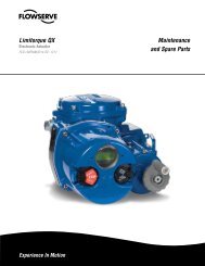
SoftTools Suite<br />
Our SoftTools software package provides all tools necessary<br />
to establish communications with your Logix positioner<br />
using a personal computer via the HART protocol.<br />
SoftTools version 7.0 introduces the most advanced and<br />
comprehensive set of valve and positioner diagnostics<br />
available today.<br />
Logix/SoftTools Features:<br />
• <strong>Valve</strong>/package identification, including tag number, valve<br />
specifications, and actuator configuration.<br />
• Custom characterization, allowing the user to adjust a 21-point<br />
characterization curve to change the response of the positioner<br />
to meet process requirements.<br />
• Positioner performance tests measure hysteresis, deadband,<br />
linearity, and repeatability.<br />
• Signature comparisons can be performed by evaluating a<br />
stored “installed” signature curve to current performance.<br />
• Dual gain tuning of the Logix positioner allows the user to make<br />
large step changes with minimal overshoot, while achieving the<br />
resolution to respond to very small step changes.<br />
SoftTools Performance Testing<br />
HART Accessories<br />
<strong>Automax</strong> also offers a variety of accessories to complete your<br />
HART installation.<br />
flowserve.com<br />
• HART Handheld – offers single tool, remote configuration,<br />
calibration, and control of HART devices.<br />
• HART Cable Modem – enables communication between a<br />
laptop or desktop PC through PCMCIA or RS232 interface.<br />
• HART Filter – protects HART digital communication imposed<br />
on 4-20 mA signal from noise generated by DCS.<br />
SoftTools Signature Comparison<br />
SoftTools 21-point Characterization Curve<br />
21
22<br />
Limit Switch and Positioner Products<br />
<strong>Automax</strong> limit switch and positioner products were<br />
designed with harsh chemical environments in mind.<br />
Users do not normally expose valve automation<br />
accessories directly to concentrated chemicals continually,<br />
however, mild concentrations do exist in plant<br />
atmospheres. This guide provides chemical compatibility<br />
for materials used in exposed parts, i.e., housings, covers<br />
and visual indicators.<br />
WR & FR - Series Aviator/BUSwitch – General<br />
Electric Noryl ®<br />
Noryl, a modified PPO resin, features high hydrolytic stability,<br />
meaning that it does not absorb moisture readily, making it well<br />
suited for high humidity and steam environments. Noryl offers<br />
good resistance to most acids, bases, detergents and aqueous<br />
solutions. Halogenated and aromatic solvents may soften or<br />
dissolve this material.<br />
PL-Series UltraSwitch – DuPont Zytel ®<br />
Zytel ® , a polyamide resin, features resistance to low concentrations<br />
of bases, solvents and salts. This high-strength engineered<br />
resin provides an excellent enclosure for harsh corrosive<br />
environments.<br />
UltraDome & Pharos Visual Indicators – General<br />
Electric Lexan ®<br />
Lexan, a polycarbonate resin, is extremely tough and generally<br />
is not affected by low concentrations of acids, alcohols and<br />
alkalis. High concentrations should be avoided. Mild detergents,<br />
pure petroleum greases and pure silicone greases are generally<br />
compatible. Avoid solvents.<br />
GL & XCL-Series UltraSwitch, Apex 7000/8000 &<br />
Logix Positioners, XV-Series Aviator/BUSwitch<br />
- Dichromate Conversion Undercoat with Polyester<br />
Powder Top Coat or Epoxy Coating<br />
The dichromate conversion coating provides improved adhesion<br />
of the top-coat, retards mildew formation, and provides<br />
extra protection against oxidation, particularly on unpainted<br />
surfaces such as the interior. Polyester provides general<br />
protection against low concentrations of some acids and alkalis.<br />
Avoid bases. Optional epoxy coating provides better chemical<br />
resistance, but has a tendency to chalk under direct exposure to<br />
ultraviolet light.<br />
Chemical Concentration Noryl ® Zytel ® Lexan ® Polyester Epoxy<br />
Acids<br />
Acetic 5% E C C U U<br />
Acetic 90% E U — U U<br />
Citric 5% — C C E E<br />
Formic 90% — U U U E<br />
Hydrochloric 10% E U E C E<br />
Nitric 10% E U C (D) U E<br />
Nitric 75% C U C (D) U C<br />
Phosphoric 5% E U E C C<br />
Sulfuric 5% E U C C C<br />
Sulfuric<br />
Bases<br />
30% E U C C C<br />
Ammonium Hydroxide 10% — C (L) U U E<br />
Potassium Hydroxide 10% E C U U E<br />
Sodium Hydroxide<br />
Solvents<br />
10% E C (L) U U E<br />
Acetone — C U U U<br />
Ethyl Acetate (Ester) C E U C C<br />
Methanol E E U E E<br />
Methylene Chloride — C U U U<br />
Toluene<br />
Salts<br />
— E U C E<br />
Sodium Bicarbonate E E — E E<br />
Sodium Chloride<br />
Miscellaneous<br />
10% E C (L) E E E<br />
Ammonia E C — — —<br />
Chlorox E C — — —<br />
Mineral Oil E — — E E<br />
E = Excellent (chemical has no effect)<br />
C = Compatible, but material slightly affected by chemical:<br />
L = greater than 1% dimensional change<br />
D = discoloration<br />
U = Unsatisfactory (chemical attacked material)<br />
— = No test data or experience available
flowserve.com<br />
23
FCD AXENBR0006-05 Printed in USA. (Replaces AUTO-24)<br />
To find your local <strong>Flowserve</strong> representative:<br />
For more information about <strong>Flowserve</strong> <strong>Corporation</strong>, visit<br />
www.flowserve.com or call USA 1 800 225 6989.<br />
<strong>Flowserve</strong> <strong>Corporation</strong> has established industry leadership in the design and manufacture of its products. When properly selected, this <strong>Flowserve</strong> product is designed to perform its<br />
intended function safely during its useful life. However, the purchaser or user of <strong>Flowserve</strong> products should be aware that <strong>Flowserve</strong> products might be used in numerous applications<br />
under a wide variety of industrial service conditions. Although <strong>Flowserve</strong> can (and often does) provide general guidelines, it cannot provide specific data and warnings for all possible<br />
applications. The purchaser/user must therefore assume the ultimate responsibility for the proper sizing and selection, installation, operation, and maintenance of <strong>Flowserve</strong> products.<br />
The purchaser/user should read and understand the Installation Operation Maintenance (IOM) instructions included with the product, and train its employees and contractors in the safe<br />
use of <strong>Flowserve</strong> products in connection with the specific application.<br />
While the information and specifications contained in this literature are believed to be accurate, they are supplied for informative purposes only and should not be considered certified or<br />
as a guarantee of satisfactory results by reliance thereon. Nothing contained herein is to be construed as a warranty or guarantee, express or implied, regarding any matter with respect<br />
to this product. Because <strong>Flowserve</strong> is continually improving and upgrading its product design, the specifications, dimensions and information contained herein are subject to change<br />
without notice. Should any question arise concerning these provisions, the purchaser/user should contact <strong>Flowserve</strong> <strong>Corporation</strong> at any one of its worldwide operations or offices.<br />
© 2006 <strong>Flowserve</strong> <strong>Corporation</strong>, Irving, Texas, USA. <strong>Flowserve</strong> is a registered trademark of <strong>Flowserve</strong> <strong>Corporation</strong>.<br />
flowserve.com<br />
<strong>Flowserve</strong> <strong>Corporation</strong><br />
Flow Control<br />
1978 Foreman Drive<br />
Cookeville, Tennessee 38501<br />
Phone: 931 432 4021<br />
Fax: 931 432 3105<br />
www.flowserve.com<br />
<strong>Flowserve</strong> Ahaus GmbH<br />
Von Braun Straße 19a<br />
D-48683 Ahaus<br />
Germany<br />
Phone: +49 2561 686-0<br />
Fax: +49 2561 686-39<br />
<strong>Flowserve</strong> Pte. Ltd.<br />
12 Tuas Avenue 20<br />
Republic of Singapore 638824<br />
Phone: 65 862 3332<br />
Fax: 65 862 2800<br />
<strong>Flowserve</strong> PMV<br />
Korta Gatan 9<br />
SE-171 54 Solna<br />
Sweden<br />
Phone: 46(0) 8555 106 00<br />
Fax: 46(0) 8555 106 01<br />
<strong>Flowserve</strong> Flow Control UK<br />
A division of <strong>Flowserve</strong> GB Ltd<br />
Burrell Road, Haywards Heath,<br />
West Sussex, RH16 1TL<br />
Phone: +44 (0)1444 314400<br />
Fax: +44 (0)1444 314401<br />
<strong>Flowserve</strong> China<br />
Room A1 & A2 , 22nd Floor<br />
Hanwei Plaza No. 7<br />
Guanghua Rd., Chaoyang District<br />
Beijing, 10004<br />
Phone: +86 10 59210600<br />
<strong>Flowserve</strong> Spa<br />
Via Prealpi, 30<br />
Cormano, Italy 20032<br />
Phone: +39 02 663251