Milltronics MD-36 Speed Sensor - Siemens
Milltronics MD-36 Speed Sensor - Siemens
Milltronics MD-36 Speed Sensor - Siemens
Create successful ePaper yourself
Turn your PDF publications into a flip-book with our unique Google optimized e-Paper software.
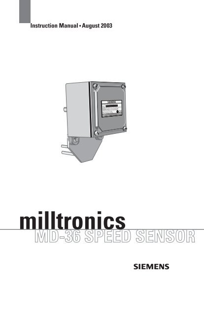
Instruction Manual August 2003<br />
milltronics<br />
<strong>MD</strong>-<strong>36</strong> SPEED SENSOR
Safety Guidelines<br />
Warning notices must be observed to ensure personal safety as well as that of others, and to<br />
protect the product and the connected equipment. These warning notices are accompanied<br />
by a clarification of the level of caution to be observed.<br />
Qualified Personnel<br />
This device/system may only be set up and operated in conjunction with this manual.<br />
Qualified personnel are only authorized to install and operate this equipment in accordance<br />
with established safety practices and standards.<br />
Warning: This product can only function properly and safely if it is correctly transported,<br />
stored, installed, set up, operated, and maintained.<br />
Note: Always use product in accordance with specifications.<br />
Copyright <strong>Siemens</strong> <strong>Milltronics</strong> Process<br />
Instruments Inc. 2003. All Rights Reserved<br />
This document is available in bound version and in<br />
electronic version. We encourage users to<br />
purchase authorized bound manuals, or to view<br />
electronic versions as designed and authored by<br />
<strong>Siemens</strong> <strong>Milltronics</strong> Process Instruments Inc.<br />
<strong>Siemens</strong> <strong>Milltronics</strong> Process Instruments Inc. will<br />
not be responsible for the contents of partial or<br />
whole reproductions of either bound or electronic<br />
versions.<br />
© <strong>Siemens</strong> <strong>Milltronics</strong> Process Instruments Inc. 2003<br />
Disclaimer of Liability<br />
While we have verified the contents of<br />
this manual for agreement with the<br />
instrumentation described, variations<br />
remain possible. Thus we cannot<br />
guarantee full agreement. The<br />
contents of this manual are regularly<br />
reviewed and corrections are included<br />
in subsequent editions. We welcome<br />
all suggestions for improvement.<br />
Technical data subject to change.<br />
MILLTRONICS®is a registered trademark of <strong>Siemens</strong> <strong>Milltronics</strong> Process Instruments Inc.<br />
Contact SMPI Technical Publications at the following address:<br />
Technical Publications<br />
<strong>Siemens</strong> <strong>Milltronics</strong> Process Instruments Inc.<br />
1954 Technology Drive, P.O. Box 4225<br />
Peterborough, Ontario, Canada, K9J 7B1<br />
Email: techpubs@siemens-milltronics.com<br />
For the library of SMPI instruction manuals, visit our Web site: www.siemens-milltronics.com
Table of Contents<br />
Introduction ..........................................................................................................................3<br />
Safety Notes .............................................................................................................................................3<br />
Product Warnings .........................................................................................................................3<br />
<strong>Milltronics</strong> <strong>MD</strong>-<strong>36</strong> <strong>Speed</strong> <strong>Sensor</strong> ........................................................................................................4<br />
The Manual ...............................................................................................................................................4<br />
Specifications ......................................................................................................................5<br />
Operation ..............................................................................................................................7<br />
<strong>MD</strong>-<strong>36</strong>/<strong>MD</strong>-<strong>36</strong>A/<strong>MD</strong>-<strong>36</strong>SS Operation .................................................................................................7<br />
<strong>MD</strong>-<strong>36</strong> IS Operation ................................................................................................................................7<br />
Dimensions ..........................................................................................................................8<br />
<strong>MD</strong>-<strong>36</strong>, <strong>MD</strong>-<strong>36</strong>A, <strong>MD</strong>-<strong>36</strong> IS .........................................................................................................8<br />
<strong>MD</strong>-<strong>36</strong>SS ........................................................................................................................................10<br />
Mounting ............................................................................................................................ 12<br />
Floating Pulley Mount ................................................................................................................12<br />
Fixed Shaft Mount .......................................................................................................................14<br />
Interconnection ................................................................................................................. 15<br />
<strong>MD</strong>-<strong>36</strong> <strong>Speed</strong> <strong>Sensor</strong>/Integrator Connection ......................................................................15<br />
<strong>MD</strong>-<strong>36</strong> IS <strong>Speed</strong> <strong>Sensor</strong>/Isolator/Integrator Connection ..................................................15<br />
Wiring Diagram (<strong>MD</strong>-<strong>36</strong> IS only) ..............................................................................................16<br />
Parts Lists ........................................................................................................................... 17<br />
<strong>MD</strong>-<strong>36</strong>/<strong>MD</strong>-<strong>36</strong>A/<strong>MD</strong>-<strong>36</strong> IS Parts List ......................................................................................17<br />
<strong>MD</strong>-<strong>36</strong>SS Parts List .....................................................................................................................19<br />
Maintenance ......................................................................................................................21<br />
i<br />
Table of Contents
Table of Contents<br />
ii
Introduction<br />
Safety Notes<br />
Special attention must be paid to warnings and notes highlighted from the rest of the text<br />
by grey boxes.<br />
Safety marking symbols<br />
Product Warnings<br />
WARNING: means that failure to observe the necessary<br />
precautions can result in death, serious injury, and/or<br />
considerable material damage.<br />
CAUTION: means that failure to observe the necessary precautions can<br />
result in considerable material damage.<br />
Note: means important information about the product or that part of the operating<br />
manual.<br />
Alternating Current<br />
Direct Current<br />
Earth (ground) Terminal<br />
Protective Conductor Terminal<br />
WARNINGS:<br />
♦ Repair of this equipment shall be carried out by suitably trained<br />
personnel in accordance with the applicable Codes of Practice.<br />
♦ If the equipment is likely to come into contact with aggressive<br />
substances, then it is the responsibility of the user to use suitable<br />
precautions that prevent it from being adversely affected.<br />
♦ The <strong>MD</strong>–<strong>36</strong> <strong>Speed</strong> <strong>Sensor</strong>s are to be used only in the manner outlined<br />
in this manual or protection provided to the equipment may be<br />
impaired.<br />
7ML19985DB01 <strong>Milltronics</strong> <strong>MD</strong>-<strong>36</strong> <strong>Speed</strong> <strong>Sensor</strong> – INSTRUCTION MANUAL Page 3<br />
English
English<br />
<strong>Milltronics</strong> <strong>MD</strong>-<strong>36</strong> <strong>Speed</strong> <strong>Sensor</strong><br />
The <strong>Milltronics</strong> <strong>MD</strong>-<strong>36</strong> is a general purpose and hazardous rated speed sensor. The<br />
sensor, coupled to the motor or pulley shaft, converts the rotation of its input shaft into an<br />
encoded speed signal. The speed signal is transmitted to the integrating electronics for<br />
use in calculating the rate of material flow.<br />
<strong>Siemens</strong> <strong>Milltronics</strong> provides a full range of electronic integrators:<br />
• Compuscale III • <strong>Milltronics</strong> BW 100 • <strong>Milltronics</strong> BW 500<br />
The <strong>MD</strong>-<strong>36</strong> sensors can also be used with older model <strong>Siemens</strong> <strong>Milltronics</strong> integrators:<br />
• Compuscale<br />
• Compuscale II<br />
For further information about <strong>Siemens</strong> <strong>Milltronics</strong> products,<br />
go to www.siemens-milltronics.com.<br />
The Manual<br />
• Compuscale IIA<br />
• Compu-M<br />
Notes<br />
• Please follow the installation and operating procedures for a quick, trouble-free<br />
installation and to ensure the maximum accuracy and reliability of your <strong>Siemens</strong><br />
<strong>Milltronics</strong> weighing system.<br />
• This manual applies to the <strong>MD</strong>-<strong>36</strong> <strong>Speed</strong> <strong>Sensor</strong>s only. Please consult the<br />
separate integrator and belt scale manuals for operating instructions.<br />
This manual will help you set up your <strong>MD</strong>-<strong>36</strong> <strong>Speed</strong> <strong>Sensor</strong> for optimum performance. We<br />
always welcome suggestions and comments about manual content, design, and<br />
accessibility.<br />
Please direct your comments to techpubs@siemens-milltronics.com.<br />
Page 4 <strong>Milltronics</strong> <strong>MD</strong>-<strong>36</strong> <strong>Speed</strong> <strong>Sensor</strong> – INSTRUCTION MANUAL 7ML19985DB01
Specifications<br />
Power<br />
• <strong>MD</strong>-<strong>36</strong>/<strong>MD</strong>-<strong>36</strong>A/<strong>MD</strong>-<strong>36</strong>SS: +15 V DC, 25 mA from integrator<br />
• <strong>MD</strong>-<strong>36</strong> IS: +5, – 25 V DC from IS Switch Isolator<br />
Temperature<br />
Input<br />
• – 40 to 55 °C (–40 to 130 °F)<br />
• shaft rotation 0 to 2,000 rpm, bi-directional<br />
Output<br />
<strong>MD</strong>-<strong>36</strong>/<strong>MD</strong>-<strong>36</strong>A/<strong>MD</strong>-<strong>36</strong>SS:<br />
• open collector sinking output, max. 25 mA at 15 V DC<br />
• <strong>36</strong> pulses / revolution<br />
• 0 to 2,000 rpm = 0 to 1200 Hz<br />
<strong>MD</strong>-<strong>36</strong> IS:<br />
• load current: 0 – 15mA<br />
• <strong>36</strong> pulses per revolution<br />
• 0 to 2000 rpm = 0 to 1200 Hz<br />
Input: Output<br />
• 1:1 (speed ratio)<br />
Enclosure<br />
• <strong>MD</strong>-<strong>36</strong> and <strong>MD</strong>-<strong>36</strong> IS: aluminum rating – Type 4/NEMA 4/IP 65<br />
• <strong>MD</strong>-<strong>36</strong>A: aluminum<br />
• <strong>MD</strong>-<strong>36</strong>SS: 304 stainless steel<br />
7ML19985DB01 <strong>Milltronics</strong> <strong>MD</strong>-<strong>36</strong> <strong>Speed</strong> <strong>Sensor</strong> – INSTRUCTION MANUAL Page 5<br />
English
English<br />
Approvals<br />
• <strong>MD</strong>-<strong>36</strong>: CSA, FM – Class II, Gr. E, F&G, Class III, CE<br />
• <strong>MD</strong>-<strong>36</strong> IS:<br />
• ATEX: II 2 G, EEx ia IIC T6 (with suitable IS Switch Isolator)<br />
• CSA/FM (with suitable IS Switch Isolator or Switch Amplifier): Class I, Div. 1,<br />
Groups A,B,C, and D. Also Class II, Div. 1, Groups E,F, and G system approval<br />
• CE<br />
• <strong>MD</strong>-<strong>36</strong>A, <strong>MD</strong>-<strong>36</strong>SS: CE<br />
Switch and Isolator Approvals<br />
Note: The Approval Ratings for the Proximity Switch and the IS Switch Isolator are<br />
the property of Pepperl+Fuchs. Copies of these Approval Certificates may be<br />
obtained at www.siemens-milltronics.com.<br />
Proximity Switch Approval Ratings (Pepperl+Fuchs #SJ3.5-N)<br />
• ATEX: II 2 G, EEx ia IIC T6 (with suitable IS Switch Isolator) 1<br />
• CSA/FM (with suitable IS Switch Isolator or Switch Amplifier): Class I, Div. 1, Groups<br />
A,B,C, and D. Also Class II, Div. 1, Groups E,F, and G system approval<br />
IS Switch Isolator (Pepperl+Fuchs #KFA5-SOT2-Ex2 and #KFA6-SOT2-Ex2)<br />
• ATEX: II (1) G, [EEx ia] IIC<br />
• CSA/FM: Class I, Div. 1, Groups A,B,C, and D. Also Class II, Div. I, Groups E,F, and G.<br />
Cable (optional)<br />
• Belden 8770, 3 wire shielded, 0.75 mm 2 (18 AWG) or equivalent<br />
• max. run 305 m (1000 ft.)<br />
1.<br />
Based on the ATEX rating of the NAMUR slotted sensor and CSA/FM system<br />
approvals.<br />
Page 6 <strong>Milltronics</strong> <strong>MD</strong>-<strong>36</strong> <strong>Speed</strong> <strong>Sensor</strong> – INSTRUCTION MANUAL 7ML19985DB01
Operation<br />
The speed sensor consists of a main shaft rotating in a bearing assembly fixed to the<br />
enclosure. The shaft turns a toothed disk divided into <strong>36</strong> teeth, each separated by a gap<br />
equal to the tooth width. In the <strong>MD</strong>-<strong>36</strong>/<strong>MD</strong>-<strong>36</strong>A/<strong>MD</strong>-<strong>36</strong>SS, the encoder card is mounted<br />
so that the two optocouplers straddle the disk’s teeth.<br />
<strong>MD</strong>-<strong>36</strong>/<strong>MD</strong>-<strong>36</strong>A/<strong>MD</strong>-<strong>36</strong>SS Operation<br />
Power from the integrating device energizes the two optocoupler LEDs and feeds the<br />
5Vdc regulator. The 5Vdc bus powers the logic circuitry and the output driver transistors.<br />
As the shaft rotates, the <strong>36</strong>-tooth wheel modulates the light crossing within each<br />
optocoupler. The resulting outputs are two 50% duty cycle square waves that are phase<br />
shifted by 90 degrees electrical or 1/4 cycle (one cycle of <strong>36</strong>0 degrees electrical<br />
corresponds to the width of one tooth and one gap). This configuration provides<br />
directional discrimination.<br />
The optocouplers’ square wave outputs are converted into clockwise (CW) and<br />
counterclockwise (CCW) square wave output signals by the intermediate logic. When the<br />
shaft rotates in a CW direction, the logic produces pulses at the CW output and the CCW<br />
output is disabled. When the shaft rotates in a CCW direction, the logic produces pulses<br />
at the CCW output and the CW output is disabled.<br />
The speed sensor is immune to any external vibration that would cause the toothed<br />
wheel to oscillate 1/4 cycle (1/2 tooth width or 5° of shaft rotation) or less.<br />
<strong>MD</strong>-<strong>36</strong> IS Operation<br />
The <strong>MD</strong>-<strong>36</strong> IS <strong>Speed</strong> <strong>Sensor</strong> contains a Pepperl + Fuchs, NAMUR rated, inductive<br />
proximity sensor, model # SJ3.5-N, consisting of an oscillator and a coil. The oscillator<br />
creates a fequency which is emitted from the coil and out the face of the sensor.<br />
When a metal target enters this radiated field, eddy currents are indicated on this target.<br />
As the target moves closer to the sensor, the energy required from the oscillator<br />
increases. The IS switch isolator monitors the change in the oscillator load, triggering the<br />
output when a predetermined level is reached.<br />
7ML19985DB01 <strong>Milltronics</strong> <strong>MD</strong>-<strong>36</strong> <strong>Speed</strong> <strong>Sensor</strong> – INSTRUCTION MANUAL Page 7<br />
English
English<br />
Dimensions<br />
<strong>MD</strong>-<strong>36</strong>, <strong>MD</strong>-<strong>36</strong>A, <strong>MD</strong>-<strong>36</strong> IS<br />
Front View<br />
218 mm<br />
(8.6”)<br />
142 mm<br />
(5.2”)<br />
71 mm<br />
(2.8”)<br />
71 mm<br />
(2.8”)<br />
56 mm<br />
(2.2”)<br />
142 mm<br />
(5.6”)<br />
112 mm<br />
(4.4”)<br />
1/2” NPT plug<br />
(two places)<br />
Page 8 <strong>Milltronics</strong> <strong>MD</strong>-<strong>36</strong> <strong>Speed</strong> <strong>Sensor</strong> – INSTRUCTION MANUAL 7ML19985DB01
Side View<br />
117 mm<br />
(4.6”)<br />
ref. 61 mm<br />
(2.4”)<br />
213 mm<br />
(8.4”)<br />
61 mm<br />
(2.4”)<br />
114 mm<br />
(4.5”)<br />
84 mm (3.3”)<br />
16 mm (0.63”)<br />
Ø shaft<br />
124 mm (4.9”)<br />
21mm (0.8”)<br />
6 mm (0.25”)<br />
Ø shaft<br />
(two places)<br />
7ML19985DB01 <strong>Milltronics</strong> <strong>MD</strong>-<strong>36</strong> <strong>Speed</strong> <strong>Sensor</strong> – INSTRUCTION MANUAL Page 9<br />
English
English<br />
<strong>MD</strong>-<strong>36</strong>SS<br />
Front View<br />
239 mm<br />
(9.4”)<br />
152 mm<br />
(6.0”)<br />
19 mm<br />
(0.75”)<br />
76mm (3.0”)<br />
cable connector for<br />
3 to 9 mm (0.125” to<br />
0.25”) o.d. cable<br />
76 mm<br />
(3.0”)<br />
152 mm<br />
(6.0”)<br />
38 mm<br />
(1.5”)<br />
51 mm<br />
(2.0”) 102 mm<br />
(4.0”)<br />
Page 10 <strong>Milltronics</strong> <strong>MD</strong>-<strong>36</strong> <strong>Speed</strong> <strong>Sensor</strong> – INSTRUCTION MANUAL 7ML19985DB01
Side View<br />
127 mm<br />
(5.0”)<br />
(ref.) 76 mm<br />
(3.0”)<br />
216 mm<br />
(8.5”)<br />
61 mm<br />
(2.4”)<br />
114 mm<br />
(4.5”)<br />
86 mm (3.4”)<br />
16mm (0.63”)<br />
Ø shaft<br />
127 mm (5.0”)<br />
21 mm (0.8”)<br />
6 mm (0.25”) Ø<br />
shaft<br />
(two places)<br />
7ML19985DB01 <strong>Milltronics</strong> <strong>MD</strong>-<strong>36</strong> <strong>Speed</strong> <strong>Sensor</strong> – INSTRUCTION MANUAL Page 11<br />
English
English<br />
Mounting<br />
The <strong>MD</strong>-<strong>36</strong> speed sensor models can be coupled to a tail pulley, bend pulley, or motor<br />
shaft.<br />
There are two methods of attaching the sensor: floating and fixed.<br />
Floating Pulley Mount<br />
The input shaft and bearing assembly bear the weight of the speed sensor. The unit’s<br />
arresting bracket stops the speed sensor from rotating with the shaft.<br />
The arresting bracket straddles a section of angle iron installed by the customer. Make<br />
sure to fasten the anti-rotation spring.<br />
pulley shaft<br />
see Pulley Shaft on page 13<br />
Arresting bracket.<br />
Shorten if required. See<br />
Arresting Bracket on<br />
page13.<br />
spring<br />
angle iron (customer<br />
supplied)<br />
Notes:<br />
• When mounting the speed sensor, ensure that the shaft alignment is true to avoid<br />
stresses on the shaft bearing.<br />
• For preferred mounting locations, refer to the associated belt scale or weigh<br />
feeder application drawings.<br />
Page 12 <strong>Milltronics</strong> <strong>MD</strong>-<strong>36</strong> <strong>Speed</strong> <strong>Sensor</strong> – INSTRUCTION MANUAL 7ML19985DB01<br />
B<br />
B<br />
<strong>MD</strong>-<strong>36</strong><br />
series
Pulley Shaft<br />
M8 or 5/16-18 UNC set screw<br />
(customer supplied)<br />
Arresting Bracket (B-B Cross Section)<br />
64 mm<br />
(2.5”)<br />
25 mm<br />
(1”)<br />
127 mm<br />
(5”)<br />
(approx)<br />
arresting<br />
bracket<br />
16 mm (0.630”) min.<br />
16.07 mm (0.633”) max.<br />
.254mm (.010") A<br />
Notes:<br />
• When tail or bend pulley is not supplied by <strong>Siemens</strong> <strong>Milltronics</strong>, machining on tail/<br />
bend pulley shaft (see Pulley Shaft above) to accommodate <strong>Milltronics</strong> speed<br />
sensor is done by customer.<br />
• Arresting bracket is an anti-rotation device only and must not secure or support<br />
the speed sensor. Bearing life is greatly reduced if speed sensor is not free to<br />
"float." Use anti-rotation spring to prevent mechanical oscillation of speed sensor.<br />
• Grease mating surfaces to prevent seizing.<br />
7ML19985DB01 <strong>Milltronics</strong> <strong>MD</strong>-<strong>36</strong> <strong>Speed</strong> <strong>Sensor</strong> – INSTRUCTION MANUAL Page 13<br />
A<br />
secure with<br />
hook or bolt<br />
anti-rotation spring<br />
angle iron<br />
English
English<br />
Fixed Shaft Mount<br />
Side View<br />
motor<br />
Front View<br />
guard (to suit)<br />
8 mm (0.313”) two<br />
places<br />
13 mm (0.5”)<br />
optimum<br />
dimension<br />
C W<br />
C C W<br />
motor shaft<br />
rubber hose<br />
hose clamp (typ)<br />
16 mm (0.63”) Ø shaft<br />
<strong>MD</strong>-<strong>36</strong><br />
Series<br />
shaft rotation<br />
0.8 mm (0.03)”<br />
max. shaft<br />
offset<br />
customer supplied<br />
mounting bracket<br />
(remove supplied<br />
arresting bracket)<br />
Page 14 <strong>Milltronics</strong> <strong>MD</strong>-<strong>36</strong> <strong>Speed</strong> <strong>Sensor</strong> – INSTRUCTION MANUAL 7ML19985DB01
Interconnection<br />
CAUTION:<br />
• All wiring must be done in accordance with approved conduit, boxes, and<br />
fittings, and to procedures in accordance with all governing regulations.<br />
• Flexible conduit is recommended so excess stress is not applied to the<br />
shaft bearings<br />
• Interconnection between the speed sensor and the integrator should be<br />
made with 3-wire shielded, 18 AWG cable (Belden 8770 or equivalent).<br />
• Ground the shield at the integrator ONLY!<br />
<strong>MD</strong>-<strong>36</strong> <strong>Speed</strong> <strong>Sensor</strong>/Integrator Connection<br />
<strong>MD</strong>-<strong>36</strong> Compu III BW 100 BW 500<br />
Description Terminal TB1 TB1 TB1<br />
+ 15 V DC 1 30 8 19<br />
<strong>Speed</strong> Out<br />
(CW) 1 2<br />
(31) 2<br />
(7) (16)<br />
<strong>Speed</strong> Out<br />
(CCW)<br />
3<br />
(31) (7) (16)<br />
Common 4 32 6 17<br />
Ground G N/C3 N/C N/C<br />
1. To determine direction of rotation, see Front View mounting<br />
on page 14.<br />
2. Terminal positions in brackets denote that only one signal<br />
may be connected at one time.<br />
3. N/C = No Connection<br />
<strong>MD</strong>-<strong>36</strong> IS <strong>Speed</strong> <strong>Sensor</strong>/Isolator/Integrator Connection<br />
<strong>MD</strong>-<strong>36</strong> IS<br />
IS Switch Isolator<br />
(P&F #KFA5-S0T2-Ex2)<br />
BW 100 BW 500<br />
Terminal Terminal TB1 TB1<br />
3 1<br />
4 3<br />
7 7 16<br />
8 17 14<br />
7ML19985DB01 <strong>Milltronics</strong> <strong>MD</strong>-<strong>36</strong> <strong>Speed</strong> <strong>Sensor</strong> – INSTRUCTION MANUAL Page 15<br />
English
English<br />
Wiring Diagram (<strong>MD</strong>-<strong>36</strong> IS only)<br />
Hazardous Area<br />
<strong>Siemens</strong> <strong>Milltronics</strong><br />
<strong>MD</strong>-<strong>36</strong> IS<br />
S<br />
I<br />
G<br />
S<br />
I<br />
G<br />
2 conductor, 18AWG<br />
shielded cable<br />
(customer supplied)<br />
Non-Hazardous Area<br />
IS Switch Isolator<br />
(Pepperl+Fuchs #KFA5-SOT2-Ex2<br />
(customer supplied)<br />
1 2 3 4 5 1 2 3 4 5 6 7 8 9 10 11 12 13 14 15<br />
3 4<br />
S<br />
I<br />
G<br />
E<br />
X<br />
C<br />
115 Vac<br />
See Note<br />
below.<br />
<strong>Siemens</strong> <strong>Milltronics</strong><br />
Integrators<br />
SIG EXE- SHLD<br />
16 14 20 BW 500<br />
7 17 11 BW 100<br />
Refer to integrator installation<br />
diagram.<br />
Note: The 115V version is shown. If 230V is required, use isolation barrier Pepperl +<br />
Fuchs #KFA6-SOT2-Ex2.<br />
Page 16 <strong>Milltronics</strong> <strong>MD</strong>-<strong>36</strong> <strong>Speed</strong> <strong>Sensor</strong> – INSTRUCTION MANUAL 7ML19985DB01
Parts Lists<br />
<strong>MD</strong>-<strong>36</strong>/<strong>MD</strong>-<strong>36</strong>A/<strong>MD</strong>-<strong>36</strong> IS Parts List<br />
Item Description Qty Item Description Qty<br />
1<br />
2<br />
Enclosure<br />
Screw, 6-32 x 5/16<br />
1<br />
3<br />
16<br />
<strong>MD</strong>-<strong>36</strong>/<strong>36</strong>A: <strong>Speed</strong> Pickup Card Ver.3<br />
<strong>MD</strong>-<strong>36</strong> IS: Mounting Plate<br />
1<br />
1<br />
3 External Lockwasher #6 5 17 Binding Screw, Slot, 6 - 32 x 5/8 4<br />
4 Gasket, Bearing Assembly 1 18 Cap Screw, Socket, 10 - 32 4<br />
5 <strong>MD</strong>-<strong>36</strong> Bearing Assembly 1 19 Lockwasher, Split #10 4<br />
5a <strong>MD</strong>-<strong>36</strong>A Bearing Assembly 1 20 Binding Screw, Slot, 4 - 40 3<br />
6 <strong>MD</strong>-<strong>36</strong> Shroud 1 21 Hex Nut, 6 - 32 2<br />
7 Disc <strong>36</strong> Tooth 1 22 Terminal Block CSA 1<br />
8 Disc Hub 1 23 Gasket, Cover 1<br />
9 Slot Round Head Screw 1/4" 4 24 Threaded Plug, 1/2 NPT 2<br />
10 Lockwasher Split 1/4" 4 25 Enclosure Arresting Bracket 1<br />
11 Enclosure Cover 1 26 Spring Spnr. B-604 1<br />
12 Extension Shaft 1 27 Bolt, Hex 5/16 - 18 x 1 1/4 2<br />
13 Set Screw Socket, 8-32 x 3/16 2 28 Nut, Hex 5/16 - 18 2<br />
14 External Lockwasher #4 3 29 Washer, Flat 5/16 2<br />
15 Bushing 2 30 Lockwasher Split 5/16 2<br />
Side View<br />
7ML19985DB01 <strong>Milltronics</strong> <strong>MD</strong>-<strong>36</strong> <strong>Speed</strong> <strong>Sensor</strong> – INSTRUCTION MANUAL Page 17<br />
English
English<br />
Front View<br />
Note: Shown with cover removed.<br />
Bearing Assembly Replacement<br />
1. Turn off supply power from integrator and then remove speed sensor from<br />
mounting.<br />
2. Remove cover (#11) and the four bearing assembly mounting screws (#18) located<br />
externally around shaft.<br />
3. Pull out bearing assembly (#5) c/w card, disc hub, disc, and mounting brackets.<br />
4. Remove screws (#17), bushing (#15), and card (#16).<br />
5. Remove speed sensor shroud screws (#2).<br />
6. Loosen hex screw in shaft and remove extension shaft, disc hub, and disc to free<br />
bearing assembly.<br />
Page 18 <strong>Milltronics</strong> <strong>MD</strong>-<strong>36</strong> <strong>Speed</strong> <strong>Sensor</strong> – INSTRUCTION MANUAL 7ML19985DB01
<strong>MD</strong>-<strong>36</strong>SS Parts List<br />
Item Description Qty Item Description Qty<br />
1 Enclosure 1 15 SS Screw, Socket, 10 - 32 4<br />
2 Screw, 6-32 x 5/16 3 16 Lockwasher, Split #10 SS 4<br />
3 External Lockwasher #6 5 17 Binding Screw, Slot, 4 - 40 x3/8 3<br />
4 Gasket, Bearing Assembly 1 18 Hex Nut, 6 - 32 2<br />
5 Bearing Assembly 1 19 Terminal Block 1<br />
6 <strong>MD</strong>-<strong>36</strong> Shroud 1 20 Cable Connector 1<br />
7 Disc <strong>36</strong> Tooth 1 21 Enclosure Arresting Bracket 1<br />
8 Disc Hub 1 22 Locknut T&B 1/2 in # 141 1<br />
9 Extension Shaft 1 23 Spring Spnr. B-604 1<br />
10 Set Screw Socket, 8-32 x 3/16 2 24 Bolt, Hex 5/16 - 18 x 1 1/4 SS 2<br />
11 External Lockwasher #4 3 25 Lockwasher Split 5/16 SS 2<br />
12 Bushing 3 26 Nut, Hex 5/16 - 18 NC SS 2<br />
13 <strong>Speed</strong> Pickup Card Ver.3 1 27 SS Screw, Socket, 10 - 32 2<br />
14 Binding Screw, Slot, 6 - 32 x 5/8 4<br />
Side View<br />
7ML19985DB01 <strong>Milltronics</strong> <strong>MD</strong>-<strong>36</strong> <strong>Speed</strong> <strong>Sensor</strong> – INSTRUCTION MANUAL Page 19<br />
English
English<br />
Front View<br />
Note: Shown with cover removed.<br />
Bearing Assembly Replacement<br />
1. Turn off supply power from integrator and then remove speed sensor from<br />
mounting.<br />
2. Open cover and remove the four bearing assembly mounting screws (#15) located<br />
externally around shaft.<br />
3. Pull out bearing assembly (#5) c/w card, disc assembly, and <strong>MD</strong>-<strong>36</strong> shroud<br />
4. Remove screws (#14), bushing (#12), and card (#13).<br />
5. Remove <strong>MD</strong>-<strong>36</strong> shroud screws (#2) and <strong>MD</strong>-<strong>36</strong> shroud c/w terminal block (#19) and<br />
card (#13).<br />
6. Loosen hex screw in shaft and remove extension shaft, disc hub, and disc to free<br />
bearing assembly.<br />
Page 20 <strong>Milltronics</strong> <strong>MD</strong>-<strong>36</strong> <strong>Speed</strong> <strong>Sensor</strong> – INSTRUCTION MANUAL 7ML19985DB01
Maintenance<br />
The speed sensor electronics normally requires no maintenance; however, a program of<br />
periodic checks would be beneficial. The enclosure and circuit board, or NAMUR sensor<br />
should be cleaned if necessary, but only when the power is disconnected using a vacuum<br />
cleaner and a clean, dry paint brush. Check all electrical contacts for corrosion and<br />
arcing.<br />
The speed sensor bearing should be periodically checked for corrosion, wear and<br />
seizing. The bearing‘s life is dependent upon the mounting, the severity of the application,<br />
and surrounding environment.<br />
7ML19985DB01 <strong>Milltronics</strong> <strong>MD</strong>-<strong>36</strong> <strong>Speed</strong> <strong>Sensor</strong> – INSTRUCTION MANUAL Page 21<br />
English
Notes
Notes
www.siemens-milltronics.com<br />
<strong>Siemens</strong> <strong>Milltronics</strong> Process Instruments Inc.<br />
1954Technology Drive, P.O. Box 4225<br />
Peterborough, ON, Canada K9J 7B1<br />
Tel: (705) 745-2431 Fax: (705) 741-0466<br />
Email: techpubs@siemens-milltronics.com<br />
<strong>Siemens</strong> <strong>Milltronics</strong> Process Instruments Inc. 2003<br />
Subject to change without prior notice<br />
*7ml19985DB01*<br />
Printed in Canada<br />
Rev. 1.1


