Challenges for Step Stencils with Design Guidelines ... - IPC Outlook
Challenges for Step Stencils with Design Guidelines ... - IPC Outlook
Challenges for Step Stencils with Design Guidelines ... - IPC Outlook

You also want an ePaper? Increase the reach of your titles
YUMPU automatically turns print PDFs into web optimized ePapers that Google loves.
Abstract<br />
As originally published in the <strong>IPC</strong> APEX EXPO Proceedings.<br />
<strong>Challenges</strong> <strong>for</strong> <strong>Step</strong> <strong>Stencils</strong> <strong>with</strong> <strong>Design</strong> <strong>Guidelines</strong> <strong>for</strong> Solder Paste Printing<br />
Carmina Läntzsch<br />
LaserJob GmbH<br />
Fürstenfeldbruck, Germany<br />
Carmina.Laentzsch@laserjob.de<br />
Georg Kleemann<br />
LaserJob GmbH<br />
Fürstenfeldbruck, Germany<br />
The stencil printing process is one of the most critical processes in the electronic production. Due to the requirement: “faster<br />
and smaller” it is necessary to place components <strong>with</strong> different paste volume close together <strong>with</strong>out regard to solder paste<br />
printing. In our days it is no longer possible to control the solder paste volume only by adjustment of the aperture dimensions.<br />
The requirements of solder paste volumes <strong>for</strong> specific components are realized by different thicknesses of metal sheets in one<br />
stencil <strong>with</strong> so called step stencils. The step-down stencil is required when it is desirable to print fine-pitch devices using a<br />
thinner stencil foil, but print other devices using a thicker stencil foil.<br />
The paper presents the innovative technology of step-up and step-down stencils in a laser cutting and laser welding process.<br />
The step-up/step-down stencil is a special development <strong>for</strong> the adjustment of solder paste quantity, fulfilling the needs of<br />
placement and soldering. This includes the laser cutting and laser welding process as well as the resulting stencil<br />
characteristics and the potential of the printing process. Influencing factors on the printing process <strong>for</strong> step stencils like<br />
squeegee speed, squeegee angle, squeegee pressure, squeegee material, printing direction and distance from the step-edge to<br />
the nearest aperture are shown in this paper. A test layout was developed <strong>with</strong> different step heights and different distances<br />
from the nearest apertures to the step-edge to give proposals and guidelines <strong>for</strong> future designs. The transferred solder paste<br />
volume was measured <strong>with</strong> highly sophisticated systems and the results which are gained in this study allow new design<br />
guidelines.<br />
The focus of this paper is on the printing per<strong>for</strong>mance of step-up/step-down stencils and the paper ends up <strong>with</strong> a short<br />
outlook on 3D cavity printing.<br />
Key words: stencil printing, step-up/step-down stencils, transfer efficiency.<br />
Introduction<br />
In the electronic production <strong>with</strong> mixed technology, fine pitch components of 0.4mm pitch are often beside devices which<br />
need much higher paste heights. This accounts <strong>for</strong> a remarkable amount of the whole SMT production. The printing of<br />
devices <strong>with</strong> a pitch of 0.5mm and at the same time print smaller devices like 01005 or CSP <strong>with</strong> 0,3mm pitch <strong>with</strong> much<br />
less paste heights is a growing factor in the electronic production. The solution to print different paste heights <strong>with</strong>in one<br />
stencil in one printing step is a step stencil. <strong>Step</strong> stencils have been available on the market <strong>for</strong> more than 10 years and they<br />
are manufactured in different production methods. The oldest way to produce step stencils is the wet chemical etching<br />
process followed by laser cutting/welding - , milling- and electro<strong>for</strong>ming process. While the chemical etching process is<br />
becoming less important due to its limited ability of miniaturization, laser cutting and electro<strong>for</strong>ming are the most common<br />
technologies today. Both technologies differ substantially in their material, finishing process and manufacturing process.<br />
Stainless steel material is mainly used in the laser cutting process whereas nickel is the major material <strong>for</strong> the electro<strong>for</strong>ming<br />
process. As a finishing technology electrochemical polishing, mechanical brushing and electroplating are used. The different<br />
technologies of step stencils are described in a short overview.<br />
Wet Chemically Etching Process<br />
<strong>Step</strong> stencils are produced by starting from a thick stencil material, mainly stainless steel. The thickness is reduced at selected<br />
areas while using a wet chemically etching process. The remaining areas which should not be etched are protected <strong>with</strong> a film<br />
or resist. This etching process can be applied on both sides of a stencil either from the top side or the bottom side or from<br />
both sides at the same time. Nowadays the apertures of the layout are produced <strong>with</strong> a following laser cutting process,<br />
because this process shows much higher accuracy than an etching process. As a finishing process, to generate smooth<br />
aperture walls, an electro-polishing step can be added, or a nickel plating instead. The advantages of this process are the price
As originally published in the <strong>IPC</strong> APEX EXPO Proceedings.<br />
and the short delivery time. The disadvantages are the inaccuracy and the limited stencil thickness. <strong>Step</strong> stencils below<br />
100µm thickness in an etching process are difficult to produce.<br />
Milling Process<br />
The milling process is quite similar to the etching process. Starting from a thick stencil material, the thickness is reduced at<br />
selected areas <strong>with</strong> a CNC controlled system. <strong>Step</strong>s can be produced on both sides of a stencil. Later on the apertures are<br />
made <strong>with</strong> a laser cutting process <strong>for</strong> achieving smooth side walls an electro-polishing step is added. The advantage of this<br />
process is the accuracy in the step heights and the low tolerances of the laser cutting process.<br />
Electro<strong>for</strong>ming Process<br />
On a copper mandrel substrate a photo resist is applied which carries a negative photo resist image of the aperture design.<br />
After developing by light exposure a negative image is created on the mandrel which covers only the stencil apertures<br />
locations. A plating process builds up nickel to the required thickness around the resist areas. The remaining photo resist is<br />
removed from the apertures and the foil is separated from the mandrel. The advantages of this process are the smooth side<br />
walls of the apertures and the higher hardness of the nickel in comparison to stainless steel, which results in a longer shelf life<br />
of the stencil. High costs are the disadvantage.<br />
Laser Cutting – Laser Welding Process<br />
The technique is a combination of a laser cutting and laser welding process. In the first step a laser cut opening is produced in<br />
the size of the desired step-up or step-down area. In a second step a stainless steel material <strong>with</strong> the requested thickness is<br />
laser welded <strong>with</strong> exact the same size of the <strong>for</strong>mer opening. The apertures are generated simultaneously in the step area and<br />
on the base material.<br />
Afterwards a finishing process is carried out. It is a brushing process which removes the burr from the laser cutting process.<br />
The stainless steel material <strong>for</strong> the step areas is available in 10µm steps starting from 20um to 300µm to adjust the solder<br />
paste volume <strong>for</strong> each specific component. To guarantee an exact foil thickness of ±3% and absolutely planarity of the step<br />
area a special pre-treatment of the stainless steel material is necessary. The spacing of the welding seam is around 200µm and<br />
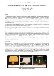
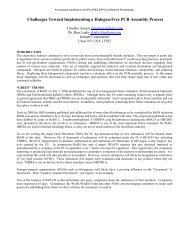
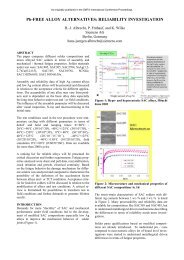
the edges are automatically rounded off due to the welding process. No additional process step is necessary, see picture 1.<br />
Picture 1- rounded corner of step-down edge<br />
With this process the squeegee is easily adjustable to the step height or depth <strong>with</strong>out damaging or abrading the squeegee<br />
blade. The flexibility of this technology is enormous, even used stencils step areas are replaceable and the costs <strong>for</strong> a new<br />
stencil are saved. With this technology step-down or step-up areas are possible on both sides of the stencil at the same time.<br />
The advantages of this manufacturing process are the flexibility, short delivery time –6 hour service possible- and the high<br />
precision of the laser cutting and laser welding process.<br />
The production of these stencils takes place in air conditioned rooms <strong>with</strong> a fiber laser. The fiber laser is characterized by a<br />
significantly better laser beam than common used laser systems. The distinct lower cutting opening of 20µm <strong>with</strong> equal depth<br />
of focus sharpness allows a reduced heat input into the material. At the same time the edges are less coarse and the cutting of<br />
the stencils is more accurate. The precision of the lightly conical apertures allows a more efficient solder paste release and<br />
increases the process window in the pick and place operation. To produce true to size stencils it is necessary that the laser<br />
cutting process is carried out in strained conditions. With this procedure we guarantee an aperture positioning of ±10µm and<br />
an aperture size accuracy of ±3µm.<br />
Description of the study<br />
Two different test series are per<strong>for</strong>med to demonstrate the optimum printing settings. The settings are squeegee pressure,<br />
squeegee speed, squeegee angle and squeegee material. The printing experiments are accomplished by observing the amount<br />
of paste residues on the surface of the stencil near by the step edge. Test series 1 is based on printing parameters that are<br />
similar to industrial conditions. Test series 2 is focused on the printing result in terms of transferred solder paste volume in<br />
dependence of the keep-out distance of the nearest aperture to the step edge. The parameters are listed in table 1.
As originally published in the <strong>IPC</strong> APEX EXPO Proceedings.<br />
To achieve good printing quality <strong>with</strong> step stencils it is important to know the interaction of squeegee speed, squeegee<br />
pressure and squeegee angle on the printing results and on the transferred solder paste. The chosen step height <strong>for</strong> test series 1<br />
was 50µm starting from a base thickness of 150µm (6mils) to a step height of 200µm (8mils).<br />
Table 1- Experimental setup of test series 1 and 2<br />
Series 1 +2<br />
Squeegee pressure 3N/cm<br />
Squeegee speed 50mm/s<br />
Squeegee angle 60°C<br />
Test series 1<br />
All printing experiments were implemented on a DEK printer Horizon <strong>with</strong> a HERAEUS type F640SA30C5-89M30 solder<br />
paste. A solder paste inspection system of KOH YOUNG is used to characterize the printing results. The inspection system<br />
determines the solder paste volume of each deposit on the basis of phase shift interferometry. After measurement the<br />
inspection system calculates the transfer efficiency of each solder paste deposit and writes the results into a database.<br />
The resulting database is analyzed using the statistical software MINITAB. The transfer efficiency of all deposits is<br />
illustrated in a boxplot whereas the transfer efficiency is plotted on the y axis and the print number respectively the area ratio<br />
value is plotted on the x axis. Each box is defined by the median and the lower and upper quartile. Besides the so called<br />
whisker of the statistic program, the boxplot also illustrates the outliers of the distribution.<br />
An optical microscope is used to visually inspect the paste residues on the stencil surface.<br />
Squeegee pressure<br />
The squeegee pressure plays a decisive role on the aperture filling. If the pressure is too high, the squeegee blade is scooping<br />
paste from wide apertures, causing insufficient solder filling. High squeegee pressures can cause “bleeding” of the solder<br />
paste which may lead to smearing of the bottom side of the stencil or on the print. A consequence of it is bridging. If the<br />
squeegee pressure is too low, paste is left on the top side of the stencil, causing insufficient solder paste deposits <strong>with</strong> ragged<br />
edges. In picture 2 you can see varied amounts of paste residues close to the patch edge <strong>with</strong> a step height of 50µm on the top<br />
side of a stencil using different squeegee pressures <strong>with</strong> the same squeegee speed.<br />
squeegee pressure =3N/cm, squeegee pressure = 2N/cm squeegee pressure = 4N/cm<br />
Picture 2- influence of squeegee pressure on paste residues close to step edge<br />
Squeegee speed<br />
A similar influence on the paste residues on the surface of the stencil shows the squeegee speed. If the squeegee speed is too<br />
high the squeegee blade is not able to wipe off the paste from the stencil. Insufficient filling of the aperture is the result<br />
causing improper paste release onto the PCB; solder joint defects are the consequence of it. It is to be chosen the squeegee<br />
speed which illustrate the slightest paste remains on the depression of the stencil close to the step edge. Picture 3 shows the<br />
relation of different squeegee speeds of paste residues on the surface of the stencil close to the step edge.<br />
Squeegee angle<br />
The squeegee angle influences the real actual <strong>for</strong>ce which impacts the solder paste and determines direct the transferred<br />
solder paste volume.
speed:50mm/s speed = 25mm/s speed = 75mm/s<br />
Picture 3- relationship of different squeegee speeds on paste residues<br />
A steeper angle means lower <strong>for</strong>ce impact - lower solder paste deposit -, a flat angle means higher <strong>for</strong>ce impact – higher<br />
solder paste deposit. Picture 4 illustrates the paste remains <strong>with</strong> different squeegee angles, 45° and 60°. It is obvious that the<br />
paste residues are less <strong>with</strong> an angle of 45°.<br />
Angle:60° Angle:45°<br />
As originally published in the <strong>IPC</strong> APEX EXPO Proceedings.<br />
Pictrue 4- Paste remains close to the step edge <strong>with</strong> squeegee angle of 45° and 60°<br />
Squeegee Material<br />
The squeegee material shows an influence on the wipe off behaviour of the stencil surface too. As a squeegee blade material<br />
both stainless steel and a polymer squeegee (Permalex squeegee) were used (see Picture 5). It is obvious that the Permalex<br />
squeegee shows a much cleaner stencil surface <strong>with</strong> nearly no paste remains visible.<br />
Metal squeegee Polymer squeegee<br />
Picture 5- Paste remains <strong>with</strong> close to step edge <strong>with</strong> different squeegee material<br />
Regarding test series 1 it is quite evident that the chosen printing parameters play a major role on the amount of residues on<br />
the surface of the stencil and in consequence on the transferred solder paste. For this reason the most careful attention to<br />
process parameters have to be chosen to avoid an excess of solder paste near by the step edge in the step-down area to ensure<br />
a constant transferred solder paste volume. In this experiment the best results were achieved by reducing the speed to<br />
25mm/s, by increasing the squeegee pressure up to 4N, by changing the angle to 45° and by using the Permalex squeegee.
Test series 2<br />
The stencil layout is illustrated in figure 1 and includes step-up and step-down areas <strong>with</strong> different heights and depressions.<br />
Starting from a base thickness of 150µm (6mils) height differences of ±30µm, ±50µm and +80µm were chosen.<br />
Squeegee Squeegee direction direction<br />
Aperture distance step<br />
down<br />
Figure 1: stencil layout 2<br />
Aperture distance<br />
Figure 1: overview of the stencil layout<br />
step up<br />
Patch width<br />
step down<br />
Patch width<br />
step up<br />
Figure 1- stencil layout <strong>with</strong> step-up and step-down areas<br />
Patch distance<br />
step down<br />
base thickness step down step up<br />
Patch distance<br />
step up<br />
A detailed view of the step down area <strong>with</strong> the geometry of the apertures is shown in figure 2. Circular apertures marked as<br />
KR, oblongs <strong>with</strong> the long side of the opening parallel to the printing direction marked as LY and <strong>with</strong> the long side<br />
horizontal to the printing direction marked as LX. The aperture distance in the depression to the step edge started from 0mm<br />
up to 3mm (0,118”). All apertures in <strong>for</strong>m of circles have an area ratio of 0.7 to achieve comparable results and there<strong>for</strong>e<br />
variable diameters. All oblongs have a constant length of 1000µm and an adjustable width on the stencil thickness (stencil<br />
thickness plus 100µm).<br />
The corresponding step up area is shown in figure 3 <strong>with</strong> the same geometry and distances of the apertures to the step edge as<br />
shown in figure 2.<br />
KR<br />
0 – 3mm<br />
LX<br />
<strong>Step</strong> down<br />
LY<br />
As originally published in the <strong>IPC</strong> APEX EXPO Proceedings.<br />
0 – 3mm<br />
<strong>Step</strong> up<br />
Figure 2- step down area <strong>with</strong> apertures Figure 3- step up area <strong>with</strong> apertures<br />
KR<br />
The transfer efficiency of the solder paste on the printed circuit board (PCB) was determined during the printing study and a<br />
comparison of the aperture geometries was drawn in dependence to step heights. The result is illustrated in figure 4. At a step<br />
height of -30µm transfer efficiencies above 80% were achieved on an average <strong>for</strong> circulars and oblongs. No influence of<br />
aperture geometry was visible at low height differences. At a step height of -50µm the transfer efficiency of circulars is much<br />
lower in comparison to oblongs. A transfer efficiency of 60% <strong>for</strong> circulars and 80-120% <strong>for</strong> oblongs were found on an<br />
average. But besides that the average deviation <strong>for</strong> circulars is higher too. A possible explanation <strong>for</strong> this behaviour is the<br />
increase of remaining paste residues in the very close area to the step edge by increasing step heights. This affects dramatic<br />
the paste release <strong>for</strong> circulars and there<strong>for</strong>e the transfer efficiency. However the transfer efficiency <strong>for</strong> the uncritical oblong<br />
structure LY increases (long side parallel to squeegee direction).<br />
LX<br />
LY<br />
Printing direction
Figure 4- Transfer efficiency of circulars and oblongs in step down area<br />
At the same time the transfer efficiency of solder paste was determined on the base thickness to the step-down edge. <strong>Step</strong><br />
heights of -30µm illustrates a transfer efficiency of 80% independent of structure geometry. Even at step height of +50µm<br />
and +80µm the average transfer efficiency is around 80%. The result is shown in figure 5. The analysis of test series 2 is<br />
obvious and indicates that circular apertures in the step down area are more critical to print than oblongs, especially by<br />
increasing step heights. Increasing step heights affect significantly the wipe off behaviour of solder pastes in the depression<br />
and in consequence the printing result [1]. Picture 6 demonstrates the increasing amount of paste residues at step heights of -<br />
30µm and -80µm. All apertures on the base thickness of the stencil close to the step down edge are not critical to printing as<br />
long as the paste is wiped off properly. This observation is independent of aperture geometry.<br />
Figure 5- Transfer efficiency of circulars and oblongs on base thickness<br />
-30µm -80µm<br />
Picture 6- paste residues in step down area at -30 and -80µm<br />
As originally published in the <strong>IPC</strong> APEX EXPO Proceedings.
As originally published in the <strong>IPC</strong> APEX EXPO Proceedings.<br />
Besides the comparison of transfer efficiencies of different aperture geometries, the experiment of keep-out distances from<br />
the apertures to the step edge was carried out. As a general design guide after <strong>IPC</strong> 7525A [2], the keep out distance should be<br />
0.9mm (35.4mil) <strong>for</strong> every 0.025mm (0.98mil) of step down thickness. In table 2 an overview is shown.<br />
Table 2- overview of keep-out distance of step-down stencils<br />
<strong>Step</strong> down thickness in mm Keep-out distance in step-down area<br />
0.010 (0.397mil) 0.36mm (14.1mil)<br />
0.020 (0.787mil) 0.72mm (28.3mil)<br />
0.250 (0.984mil) 0.90mm (35.4mil)<br />
0.030 (1.181mil) 1.08mm (42.5mil)<br />
0.050 (1.969mil) 1.80 mm (70.9mil)<br />
0.080 (3.14mil) 2.88mm (133.4mil)<br />
0.100 (3.937mil) 3.60mm (141.7mil)<br />
The test series of circular apertures is illustrated in figure 6, whereas the keep-out distances varied from 0.150mm up to<br />
3.3mm. The analysis of the transfer efficiency at a step height of -30µm indicates an average amount of at least 60%,<br />
at the very low distance of only 150µm to the step down edge. By using the <strong>IPC</strong> proposals <strong>for</strong> the keep-out distance, (see<br />
table 2) of 1.08mm, the experiment clearly demonstrates, even at this short distance of only 150µm, the transfer efficiency is<br />
the same as <strong>for</strong> the distance of 1.08mm and a keep-out distance is not necessarily needed <strong>for</strong> a step down height of -30µm <strong>for</strong><br />
circular apertures.<br />
At a step height of -50µm the average transfer efficiency is 60% at a keep-out distance of at least 500µm, which is much<br />
lower than the <strong>IPC</strong> proposes. At a step height of -80µm the achieved transfer efficiency at a keep-out distance of 500µm is<br />
minimum 60% <strong>with</strong> an outlier at a distance of 1.8mm. By increasing step heights the transfer efficiency is often above 100%.<br />
The relationship is explained by the fact that too much paste remains are present on the stencil surface in the very close area<br />
of the step-down edge, see picture 5. So be careful because <strong>with</strong> increasing step height more paste is transferred which can<br />
lead to bridging. The proposal of the <strong>IPC</strong> of 2.88mm is there<strong>for</strong>e a good guide.<br />
Figure 6- transfer efficiency of circles in step down area at -30µm, -50µm and -80µm<br />
Figure 7 show the transfer efficiency <strong>for</strong> oblongs Lx (long side of oblong in a 90° angle to printing direction) and figure 8 <strong>for</strong><br />
oblongs Ly (long side parallel to printing direction). Both oblong variations are uncritical to print independent of step heights<br />
of -30µm or -50µm. The transfer efficiency <strong>for</strong> both oblong types is above 60% regardless of step height and keep-out<br />
distance. For step heights of -80µm the high transfer efficiency of above 100% was again noted and a keep-out distance per<br />
<strong>IPC</strong> of 2,88mm should be used.
Figure 7- transfer efficiency of oblongs Lx in the step-down area<br />
Figure 8- transfer efficiency of oblongs Ly in the step down area<br />
3D cavity printing<br />
This type of stencil is used to print on deeper levels of a printed circuit board, by welding a stainless steel foil in <strong>for</strong>m of a<br />
step on the bottom side of the stencil, see picture 7.<br />
stencil<br />
PCB<br />
Picture 7- schematic design of a 3D cavity stencil<br />
As originally published in the <strong>IPC</strong> APEX EXPO Proceedings.<br />
The application of 3D cavity stencils allows a simultaneous paste printing process on different levels on the PCB or substrate<br />
<strong>with</strong> different paste depot heights. The levels of the stencil can differ more than several 100 microns. At a decisive cavity<br />
depth the squeegee is no longer capable to dip in the cavity and wipe off the paste remaining in the depression. To insure a<br />
proper paste print <strong>with</strong> reliable paste transfer efficiency it is absolutely necessary to wipe off the paste in the cavity.<br />
There<strong>for</strong>e you have to slot the squeegee blade to increase the flexibility of the blade at this point. The slots have to be<br />
adjusted to the cavity size, see picture 8.
Picture 8- squeegee blade <strong>with</strong> 2 slots adjusted to cavity size<br />
As originally published in the <strong>IPC</strong> APEX EXPO Proceedings.<br />
Conclusion sl<br />
vv<br />
The step stencil technology ot has been a well-established technology <strong>for</strong> years and offers a multiplicity of solutions and<br />
applications <strong>for</strong> a mixed component range. The flexibility of the laser cut and laser welding process is enormous and allows<br />
the application of 3D cavity as well. Even used stencils step areas are replaceable and thus offers a cost saving factor.<br />
Through the laser welding process the edges are automatically rounded off and the squeegee can easily adjust to step heights<br />
or depths <strong>with</strong>out damaging the squeegee blade.<br />
The settings of the printing process influence the transferred solder paste volume distinctly, especially in the depression of the<br />
very close area to the step edge <strong>with</strong> increasing step heights. The remaining paste residues in the depression affect the paste<br />
release and in consequence the transferred paste volume. The parameter settings like squeegee speed, squeegee angle,<br />
squeegee material and squeegee pressure show a significant influence on the wipe off behaviour of the solder paste in the<br />
depression of the step stencil and there<strong>for</strong>e on the transfer efficiency. Especially <strong>with</strong> uncritical aperture geometries the<br />
access of solder paste in the depression has to be considered.<br />
The aperture geometry plays a significant role in the transfer efficiency of solder paste in step down stencils especially by<br />
increasing step heights.<br />
Acknowledgements<br />
The author wants to thank Dr. Michael Rösch from Institute FAPS, University of Erlangen-Nuremberg <strong>for</strong> carrying out the<br />
test series.<br />
References<br />
[1] Michael Rösch: Potenziale und Strategien zur Optimierung des Schablonendruckprozesses in der Elektronikproduktion,<br />
August 2011<br />
[2] <strong>IPC</strong> 7525A: Stencil <strong>Design</strong> <strong>Guidelines</strong>
As originally published in the <strong>IPC</strong> APEX EXPO Proceedings.<br />
<strong>Challenges</strong> <strong>for</strong> step stencils<br />
<strong>with</strong> design guidelines <strong>for</strong> solder paste printing<br />
Carmina Läntzsch<br />
LaserJob GmbH,<br />
Fürstenfeldbruck, Germany
Contents<br />
Introduction and application of step stencils<br />
1. Manufacturing of step stensils in laser cutting and laser<br />
welding process<br />
2. Influences and process guidelines<br />
3. Experimental set-up<br />
4. 3D cavity stencil<br />
5. Summary<br />
As originally published in the <strong>IPC</strong> APEX EXPO Proceedings.
Introduction<br />
Why step stencils?<br />
mixed assembly on one PCB e.g. fine pitch components<br />
besides connectors<br />
No longer possible to adjust solder paste volume only by<br />
changing aperture dimensions<br />
Manufacturing start: year 2000<br />
As originally published in the <strong>IPC</strong> APEX EXPO Proceedings.<br />
Filing of a patent in year 2000, EP 1187517
Application of step stencils<br />
<strong>Step</strong>-up stencil<br />
Application: (<strong>IPC</strong> 7525A)<br />
This type of stencil is useful when it is desirable to<br />
print thicker solder paste in a small portion of the stencil.<br />
e.g.: an ceramic BGA where it is necessary to get 0,2mm paste<br />
height because of ball coplanarity but 0,15mm height on all<br />
other surface-mount component pads.<br />
stencil<br />
PCB<br />
As originally published in the <strong>IPC</strong> APEX EXPO Proceedings.
Application of step stencils<br />
<strong>Step</strong>-down stencil<br />
Application: (<strong>IPC</strong> 7525A)<br />
This type of stencil is useful when it is desirable to print finepitch<br />
devices using a thinner stencil foil but print other devices<br />
using thicker stencil foils.<br />
e.g.: fine pitch BGA of 0,5mm (20mil) pitch that requires a<br />
stencil thickness of 0,1mm to achieve an area ration ˃0,66. At<br />
the same time there are devices on the same board that need<br />
a thickness of 0,150mm.<br />
stencil<br />
PCB<br />
As originally published in the <strong>IPC</strong> APEX EXPO Proceedings.
Application of step stencils<br />
<strong>Step</strong> in step stencil<br />
Application: QFP component<br />
As originally published in the <strong>IPC</strong> APEX EXPO Proceedings.<br />
Base thickness of stencil: t=150µm<br />
Thickness of heat sink area: t=180µm<br />
QFP: t=120µm<br />
180µm<br />
120µm<br />
180µm<br />
120µm<br />
Pitch = 400µm<br />
Pad width: 200µm<br />
Keep-out distance:<br />
700µm
Application of step stencils<br />
step-down stencil on PCB side<br />
Application:<br />
This type of stencil is used to hide thick labels on the printed<br />
circuit board, by welding a thin foil in the stainless steel<br />
sheet, e.g. <strong>for</strong> bar code labels<br />
stencil<br />
PCB<br />
As originally published in the <strong>IPC</strong> APEX EXPO Proceedings.<br />
label
Application of step stencils<br />
<strong>Step</strong>-up stencil on squeegee side<br />
Application:<br />
This type of stencil is used to hide components<br />
on the printed circuit board, by welding a thicker foil <strong>with</strong><br />
bevel in the stainless steel sheet<br />
Stencil<br />
PCB<br />
As originally published in the <strong>IPC</strong> APEX EXPO Proceedings.<br />
component
As originally published in the <strong>IPC</strong> APEX EXPO Proceedings.<br />
Manufacturing of step stencils<br />
Laser cutting and laser welding process
As originally published in the <strong>IPC</strong> APEX EXPO Proceedings.<br />
Benefits of laser cut and laser welding process<br />
Adapted paste volume in one print process<br />
10µm- steps possbile up to 300µm<br />
Afterwards integration of patches in standard SMD stencils<br />
and PatchWork® stencils<br />
Available <strong>with</strong> NanoWork® coating<br />
Exact step thickness due to special pretreatment<br />
The same high precision in the step like rest of foil<br />
Rounded step edges due to laser welding process<br />
<strong>Step</strong>-up and step-down stencil is available on stencil- and<br />
PCB side
As originally published in the <strong>IPC</strong> APEX EXPO Proceedings.<br />
<strong>IPC</strong> 7525 stencil guidelines<br />
As a general design guide K1 should<br />
be 0,9mm [35,4mil] <strong>for</strong> every<br />
0,025mm[0,98mil] of step- down<br />
thickness.<br />
K1<br />
K1<br />
<strong>Step</strong> in mm K1 is distance <strong>for</strong>m the step edge to the nearest<br />
aperture in step –down area<br />
0,010 [0,397mil] 0,36mm [14,1mil]<br />
0,020 [0,787mil] 0,72mm [28,3mil]<br />
0,025 [0,984mil] 0,90mm [35,4mil]<br />
0,030 [1,181mil] 1,08mm [42,5mil]<br />
0,050 [1,969mil] 1,80mm [70,9mil]<br />
0,080 [3,14 mil] 2,88mm [113,4mil]<br />
0,100 [3,937mil] 3,60mm [141,7mil]<br />
Ste<br />
p
<strong>IPC</strong> 7525 stencil guidelines <strong>for</strong> step stencils<br />
A general desing guide <strong>for</strong> complete<br />
paste release is:<br />
Area ratio: ˃ 0,66<br />
Aspect ratio: ˃ 1.5<br />
As originally published in the <strong>IPC</strong> APEX EXPO Proceedings.
Influencing factors <strong>for</strong> step stencils<br />
on the printing process<br />
Squeegee speed<br />
Squeegge angle<br />
Squeegee pressure<br />
Squeegee material<br />
Squeegee direction<br />
As originally published in the <strong>IPC</strong> APEX EXPO Proceedings.<br />
Distance from the step edge to the nearest<br />
aperture in the step down area
Squeegee speed<br />
As originally published in the <strong>IPC</strong> APEX EXPO Proceedings.<br />
Squeegee speed<br />
Basic settings: speed: 50mm/s,<br />
squeegee pressure: 3N/cm, angle: 60°<br />
Basic settings: speed:50mm/s speed = 25mm/s speed = 75mm/s<br />
Picture Distance no. from 06<br />
Distance from step edge<br />
patchedge-plateau<br />
<strong>Step</strong> up 150 → 200µm<br />
Print directi<br />
Patch<br />
Squeegee direction: Patch ↑<br />
step down:<br />
step: 50µm step: 50µm<br />
Patch 50µm<br />
step: 50µm
Rakeldruck<br />
As originally published in the <strong>IPC</strong> APEX EXPO Proceedings.<br />
XXX.<br />
Squeegee pressure<br />
basic settings: V= 50mm/s,<br />
squeegee pressure: 3N/cm, angle : 60°<br />
Basic setting: speed:50mm/s, squeegee pressure = 2N/cm squeegee pressure = 4N/cm<br />
sp=3N/cm, angle:60°<br />
Print directio<br />
Distance Picture from no. step 06<br />
edge-plateau<br />
<strong>Step</strong> up 150 → 200µm<br />
Squeegee direction: ↑<br />
<strong>Step</strong> down:<br />
50µm
Squeegee angle<br />
As originally published in the <strong>IPC</strong> APEX EXPO Proceedings.<br />
Angle between squeegee and stencil<br />
The squeegee angle influences the <strong>for</strong>ce effect on paste and there<strong>for</strong>e on<br />
transfered paste volume.<br />
steeper squeegee angle: less <strong>for</strong>ce effect less paste volume<br />
flat squeegee angle: higher <strong>for</strong>ce effect higher paste volume<br />
60° 45°
Rakelwinkel<br />
As originally published in the <strong>IPC</strong> APEX EXPO Proceedings.<br />
XXX.<br />
Squeegee angle<br />
Basic settings: speed: 50mm/s,<br />
squeegee pressure: 3N/cm, angle: 60°<br />
Angle: 60° Angle: 45°<br />
Print directi<br />
Distance from step edge<br />
Picture no. 06<br />
<strong>Step</strong> up 150 → 200µm<br />
<strong>Step</strong> down:<br />
Squeegee direction: 50µm ↑
Basic setting: speed:50mm/s, sp=3N/cm,<br />
angle:60°<br />
Lotpastenkörnung<br />
As originally published in the <strong>IPC</strong> APEX EXPO Proceedings.<br />
Powder size<br />
Basic settings: speed: 50mm/s,<br />
squeegee pressure: 3N/cm, angle: 60°<br />
solder paste type 3 solder paste type 4<br />
Distance Distance from<br />
from<br />
patchedge-plateau<br />
patchedge-plateau<br />
Picture no. 06<br />
<strong>Step</strong> up 150 → 200µm<br />
Print directi<br />
Patch<br />
Squeegee direction: Patch ↑<br />
step: step: 50µm<br />
50µm
Metal squeegee<br />
Polymer squeegee<br />
Rakelmaterial<br />
As originally published in the <strong>IPC</strong> APEX EXPO Proceedings.<br />
XXX.<br />
Squeegee material<br />
basic settings: speed: 50mm/s,<br />
squeegee pressure: 3N/cm, angle: 60°<br />
Distance from step<br />
edge-plateau<br />
Print direct<br />
<strong>Step</strong> down:<br />
50µm
As originally published in the <strong>IPC</strong> APEX EXPO Proceedings.<br />
Stencil layout <strong>for</strong> step stencils
Testlayout to qualify step stencils<br />
3 step stencils <strong>with</strong> different stencil thicknesses 150 µm ± 30<br />
Squeegee<br />
direction<br />
µm, 150 µm ± 50 µm and 150 µm ± 80 µm<br />
Aperture<br />
distance step<br />
down<br />
Aperture<br />
distance step<br />
up<br />
As originally published in the <strong>IPC</strong> APEX EXPO Proceedings.<br />
step<br />
width<br />
Patch<br />
width step<br />
up<br />
Patch<br />
distance<br />
step down<br />
Patch<br />
distance<br />
step up<br />
Base<br />
thickness<br />
down<br />
up<br />
step<br />
step
As originally published in the <strong>IPC</strong> APEX EXPO Proceedings.<br />
Testlayout to qualify step stencils<br />
Detailed view: step-down<br />
Aperture<br />
step width<br />
distance step<br />
down<br />
step down<br />
0mm - 3mm 15mm<br />
10mm<br />
5mm<br />
2,5mm<br />
<strong>Step</strong> height difference: 30 µm, 50 µm, 80 µm<br />
step distance<br />
step down<br />
15mm<br />
10mm<br />
5mm<br />
2,5mm<br />
Paste transfer efficieny determined <strong>with</strong> Koh Young system
Testlayout to qualify step stencils<br />
Detailed view: step-up<br />
0mm - 3mm<br />
Aperture<br />
distance step<br />
up -plateau<br />
As originally published in the <strong>IPC</strong> APEX EXPO Proceedings.<br />
15mm<br />
10mm<br />
5mm<br />
2,5mm<br />
Patch<br />
width step<br />
up<br />
15mm<br />
10mm<br />
5mm<br />
2,5mm<br />
Patch distance<br />
step up<br />
<strong>Step</strong> height difference: 30 µm, 50 µm, 80 µm
printing direction<br />
Transfer efficiency on PCB :<br />
aperture distance step up „on plateau“<br />
KR<br />
Aperture distance<br />
step up- plateau<br />
KR<br />
LX<br />
LY<br />
Aperture distance<br />
step up- plateau<br />
LX<br />
LY<br />
As originally published in the <strong>IPC</strong> APEX EXPO Proceedings.<br />
Transfer<br />
efficiency<br />
Transfer<br />
efficiency<br />
<strong>Step</strong><br />
height<br />
30µm<br />
Apertures on step up - plateau<br />
Apertures: KR=circles, LX= oblong, LY=oblong<br />
<strong>Step</strong><br />
height<br />
30µm<br />
<strong>Step</strong><br />
height<br />
50µm<br />
Apertures on base thickness<br />
<strong>Step</strong><br />
height<br />
50µm<br />
<strong>Step</strong><br />
height<br />
80µm<br />
Apertures: KR=circles, LX= oblong, LY=oblong<br />
<strong>Step</strong><br />
height<br />
80µm
Transfer efficiency on PCB –<br />
aperture distance step down „on plateau“<br />
printing direction<br />
As originally published in the <strong>IPC</strong> APEX EXPO Proceedings.
As originally published in the <strong>IPC</strong> APEX EXPO Proceedings.<br />
Influence of step height on wipe off<br />
behavior of solder paste<br />
Stufensprunghöhe 30 µm Stufensprunghöhe 80 µm<br />
<strong>Step</strong> height 30 µm <strong>Step</strong> height 80 µm
As originally published in the <strong>IPC</strong> APEX EXPO Proceedings.<br />
Transfer efficiency in step down area
As originally published in the <strong>IPC</strong> APEX EXPO Proceedings.<br />
Transfer efficiency in step down area
As originally published in the <strong>IPC</strong> APEX EXPO Proceedings.<br />
Transfer efficiency in step down area
3D cavity stencil<br />
As originally published in the <strong>IPC</strong> APEX EXPO Proceedings.<br />
Application: to print in deeper levels of a PCB<br />
Simultaneous paste printing process on different levels of the PCB<br />
Different paste depots heights on all levels<br />
Levels can differ more than several 100 microns
3D cavity stencil<br />
Application:<br />
This type of stencil is used to print in deeper<br />
layers of a printed circuit board, by welding<br />
a foil in <strong>for</strong>m of a step in the stencil<br />
Problem: the sqeegee is no longer capable to dip in<br />
the cavity<br />
Stencil<br />
PCB<br />
As originally published in the <strong>IPC</strong> APEX EXPO Proceedings.
3D cavity stencil<br />
Solution:<br />
Two slots in the squeegee blade to increase<br />
flexibility. The slots have to be adjusted to cavity<br />
size.<br />
stencil<br />
PCB<br />
As originally published in the <strong>IPC</strong> APEX EXPO Proceedings.<br />
12,4mm<br />
10,9mm<br />
0,750 0,750<br />
12,6mm
3D cavity stencil<br />
Solution:<br />
As originally published in the <strong>IPC</strong> APEX EXPO Proceedings.<br />
Two slots in the squeegee blade to increase<br />
flexibility. The slots have to be adjusted to cavity size.<br />
10,64mm<br />
Stencil
As originally published in the <strong>IPC</strong> APEX EXPO Proceedings.<br />
Summary<br />
The laser cut and laser welding process is an innovative technology<br />
<strong>for</strong> step stencils and offers a multiplicity of solutions.<br />
Critical apertures in the step-down area close to the step edge should be avoided,<br />
because the paste remains can affect the paste release.<br />
Uncritical apertures in the step down area close to the step edge show an increase of<br />
transfer efficiency. The <strong>IPC</strong> guidelines are a good reference.<br />
The wipe off behaviour of solder paste is influenced by the squeegee speed, -pressure,<br />
-angle and –material. A reduction of squeegee speed or –angle improves the wipe off.<br />
Many thanks <strong>for</strong> your attention!