Autodata - Diagnostic Trouble Codes Fault locations and probable causes - 2004 edition
1 578 I,,,,,,,,,,, /Autodata Engine management Year: 1993-97 Engine code: ABS, AAU, AAV System: Bosch Mono-Motronic MA1.2.2 I In glovebox, driver's side General information 0 Refer to the front of this manual for general test conditions, terminology, detailed descriptions of wiring faults and a general trouble shooter for electrical and mechanical faults. Trouble codes are displayed by using an LED connected to one of the ECM terminals. The ECM fault memory can also be checked and erased using diagnostic equipment connected to the data link connector (DLC). Self-diagnosis using flash type trouble codes may not display all available diagnostic information. Carry out road test for at least 10 minutes. Ensure accelerator pedal is briefly fully depressed and engine speed exceeds 3000 rpm. Each trouble code consists of four groups of one to four flashes. A 2,5 second pause separates each trouble code group H [A]. ReDeat switch o~eration. Note trouble codes. Com~are with tro"ble code table. End of test sequence indicated by trouble code 0000 (long flashes). Switch ignition OFF. Rectify faults as necessary. Accessing Ensure ignition switched OFF. Bridge data link connector (DLC) terminals 4 and 15 with a switched lead - contacts normally open O. NOTE: DLC terminal 15 is connected to ECM terminal 11. Connect LED test lamp between data link connector (DLC) terminal 16 and ECM terminal 4 0. ECM located in plenum chamber. NOTE: DO NOT disconnect ECM multi-plug as this will erase fault memory. Start engine. Allow to idle. NOTE: If engine does not start' Crank engine for 6 seconds. Leave ignition switched ON. Operate switch for 4 seconds minimum. Release switch. Check that LED flashes. Count LED flashes. Note trouble code.
Engine management I Erasing Method 1 Ensure ignition switched OFF. Bridge data link connector (DLC) terminals 4 and 15 with a switched lead - contacts normally open 8. NOTE: DLC terminal 15 is connected to ECM terminal 11. Connect LED test lamp between data link connector (DLC) terminal 16 and ECM terminal 4 8. Access trouble codes. Switch ignition OFF. Operate switch and hold. Switch ignition ON. Release switch after 5 seconds. Check that LED flashes. ldle speed control (ISC) actuator activated. Trouble code displayed: 1232. Operate switch for 4-6 seconds to activate each of the following components: Intake manifold heater. Trouble code displayed: 4342. Evaporative emission (EVAP) canister purge valve. Trouble code displayed: 4343. After activation of last component operate switch for 4-6 seconds to display flash code 0000 (long flashes). Fault memory automatically erased. Repeat checking procedure to ensure no data remains in ECM fault memory. Method 2 Ensure ignition switched OFF. Disconnect ECM multi-plug or battery earth lead. NOTE: ECM adaptive memory may be erased causing erratic running faults. Carry out road test to allow ECM to re-learn basic values. WARNING: Disconnecting the battery may erase memory from electronic units (e.g. radio, clock). Trouble code identification type 4-digit 0000 I End of test sequence 1 - 1111 1231 1232 Fault location Engine control module (ECM) Vehicle speed sensor (VSS) Idle speed control (ISC) actuator Probable cause 2113 8 ( Crankshafl position (CKP) sensor I Insecure rotor, wiring, CKP sensor 2121 I Closed throttle position (CTP) switch Accelerator cable adjustment, CTP switch adjustment, wiring, CTP switch 221 2 2234 231 2 I Engine coolant temperature (ECT) sensor I Wiring, poor connection, ECT sensor ECM Wiring, speedometer, VSS 2322 I Intake air temperature (IAT) sensor I Wiring, IAT sensor 2341 Throttle position (TP) sensor Engine control module (ECM) - supply voltage Wiring, multi-plug incorrectly wired, ISC actuator Wiring, poor connection, TP sensor Battery, wiring 2342 I Heated oxygen sensor (H02S) 1 Wiring, H02S, heating inoperative, fuel level low 2413 4444 Heated oxygen sensor (H02S) - lambda control Mixture control (MC) No fault found Heating inoperative, exhaust leak, misfire, fuel pressurelpump, EVAP canister purge valve Fuel level low, fuel pressurelpump, intakelexhaust leak, misfire, H02S, EVAP canister purge valve, injector, excessive fuel in engine oil - 8 Trouble code may be displayed if engine is not idling during self-diagnosis due to missing CKP sensor signal. Ignore trouble code if engine starts. After repairs, erase learnt lambda control values: Wait 30 seconds. Disconnect battery or ECM multi-plug for at least 30 seconds. Carry out road test to allow ECM to re-learn basic values.
- Page 528 and 529: I 528 I,,,,,,,, b'AUwata / -REhdAUL
- Page 530 and 531: I '1 RENAULT I Transmission Model:
- Page 532 and 533: Transmission Engine code: F3R 611,
- Page 534 and 535: 1 Model: Clio 1,6 MeganelMegane Sce
- Page 536 and 537: I I_ , i I RENAULT Model: MeganelMe
- Page 538 and 539: RENAULT Model: ExtralRapidlExpress
- Page 540 and 541: Mini Metro1100 Montego 2001400 200
- Page 542 and 543: ROVER Model: Mini Metro1100 Montego
- Page 544 and 545: \ < / \ >d ; "L m ) I-_ ROVER Model
- Page 546 and 547: I 1 9- , ROVER Model: 2001CoupelCab
- Page 548 and 549: Engine management Model: 2001400/60
- Page 550 and 551: It>; Model: 20014001600 2,O TD I; /
- Page 552 and 553: N' i, - q~ - Engine management ' J
- Page 554 and 555: 1 ROVER I Transmission Model: 600 2
- Page 556 and 557: It
- Page 558 and 559: 1 558 I,,,,,,,,,, /Autodata I Engin
- Page 560 and 561: Engine management Model: 900 2,O Tu
- Page 562 and 563: I Engine management Model: 9-3 2,O
- Page 564 and 565: 'I k4 ;c SUB Model: 9-3 2,O Turbo 9
- Page 566 and 567: 1"; C jy SAAB Model: 9-3 2,O Turbo
- Page 568 and 569: Model: 9-3 2,2D Turbo (Engine manag
- Page 570 and 571: ?, 'I vg SAAB Model: 9-3 2,2D Turbo
- Page 572 and 573: I'I.+. ,>I SAAB I Engine management
- Page 574 and 575: I Transmission Model: 900 9-3 9-5 E
- Page 576 and 577: Arosa lbizalcordoba 1,011,411,611,8
- Page 580 and 581: I Engine management 5-digit type Fa
- Page 582 and 583: Engine management Probable cause 23
- Page 584 and 585: I Engine management Trouble code id
- Page 586 and 587: pJ M SEAT Model: Arosa IbizalCordob
- Page 588 and 589: 1 / Model: Arosa IbizalCordoba Tole
- Page 590 and 591: Model: Favorit 1,3 Favorit VanlForm
- Page 592 and 593: IEngine management Erasing Method 1
- Page 594 and 595: Fabia FeliciaNanlPick-up Octavia 78
- Page 596 and 597: Year: Immobilizer Model: Fabia Feli
- Page 598 and 599: Engine management I Erasing NOTE: F
- Page 600 and 601: TOYOTA Model: Corolla 1,3 Corolla 1
- Page 602 and 603: I Engine management I Except 4A-GE
- Page 604 and 605: t- Engine management Model: Corolla
- Page 606 and 607: T OYOTA I Engine management Model:
- Page 608 and 609: TOYOTA Model: Carina 11 1,6 Carina
- Page 610 and 611: Model: Carina E 1,6/1,8/2,0 Carina
- Page 612 and 613: Model: Avensis 1,611,8/2,0 Avensis
- Page 614 and 615: Model: Avensis 1,611,812,O Avensis
- Page 616 and 617: I Engine management ON OFF 5 MA B A
- Page 618 and 619: Model: MR2 1,6 MR2 2,O 3s-FE13S-GE
- Page 620 and 621: Engine management I ~~~ A B A C A B
- Page 622 and 623: Model: Celica 1,6 Celica 1,8 Celica
- Page 624 and 625: 1 TOYOTA Engine management Model: S
- Page 626 and 627: Located on main throttle butterfly
1 578 I,,,,,,,,,,,<br />
/<strong>Autodata</strong><br />
Engine management<br />
Year: 1993-97<br />
Engine code: ABS, AAU, AAV<br />
System: Bosch Mono-Motronic MA1.2.2<br />
I<br />
In glovebox, driver's side<br />
General information<br />
0 Refer to the front of this manual for general test conditions,<br />
terminology, detailed descriptions of wiring faults <strong>and</strong> a<br />
general trouble shooter for electrical <strong>and</strong> mechanical faults.<br />
<strong>Trouble</strong> codes are displayed by using an LED connected to<br />
one of the ECM terminals.<br />
The ECM fault memory can also be checked <strong>and</strong> erased<br />
using diagnostic equipment connected to the data link<br />
connector (DLC).<br />
Self-diagnosis using flash type trouble codes may not<br />
display all available diagnostic information.<br />
Carry out road test for at least 10 minutes.<br />
Ensure accelerator pedal is briefly fully depressed <strong>and</strong><br />
engine speed exceeds 3000 rpm.<br />
Each trouble code consists of four groups of one to four<br />
flashes.<br />
A 2,5 second pause separates each trouble code group H [A].<br />
ReDeat switch o~eration. Note trouble codes. Com~are with<br />
tro"ble code table.<br />
End of test sequence indicated by trouble code 0000<br />
(long flashes).<br />
Switch ignition OFF. Rectify faults as necessary.<br />
Accessing<br />
Ensure ignition switched OFF.<br />
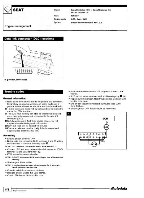
Bridge data link connector (DLC) terminals 4 <strong>and</strong> 15 with a<br />
switched lead - contacts normally open O.<br />
NOTE: DLC terminal 15 is connected to ECM terminal 11.<br />
Connect LED test lamp between data link connector (DLC)<br />
terminal 16 <strong>and</strong> ECM terminal 4 0.<br />
ECM located in plenum chamber.<br />
NOTE: DO NOT disconnect ECM multi-plug as this will erase fault<br />
memory.<br />
Start engine. Allow to idle.<br />
NOTE: If engine does not start' Crank engine for 6 seconds.<br />
Leave ignition switched ON.<br />
Operate switch for 4 seconds minimum.<br />
Release switch. Check that LED flashes.<br />
Count LED flashes. Note trouble code.


