05.02.2017
•
Views
1 424 I,,,.,,,,,,, IAutodata ME RCE D ES-B E NZ I Engine management Model: C180/200/200W220/230/230K/280 (202) E200122012801320 (1 24) E200123012801320 (210) S2801320 (140) SLK200 (170) SL2801320 (129) . , Probable cause 1 32 I Knock sensor(s) (KS) - defective ( Wiring, KS 33 34 Ignition timing, knocking - maximum retardation reached Engine control module (ECM), knock control - internal fault 35 I Seconda~y air injection (AIR) pumplrelay - malfunction 1 Wiring, AIR pumplrelay, ECM 36 37 Evaporative emission (EVAP) canister purge valve - electrical fault Transmission shift control valve - electrical fault Fuel contamination, mechanical fault 38 I Camshaft position (CMP) actuator - malfunction I Wiring, mechanical fault, CMP actuator, ECM 39 I Exhaust gas recirculation (EGR) solenoid - malfunction I Wiring, EGR solenoid, hose(s) 40 41 Transmission overload protection switch - malfunction CAN data bus, ECM - malfunction ECM 42 1 111: CAN data bus, diagnostic module - malfunction I Wiring 1 104: CAN data bus - malfunction I Wiring 43 45 Engine control module (ECM), pin 50 - starter signal With cruise control system: Cruise control, inertia fuel shut-off (IFS) switch - active Wiring, EVAP canister purge valve, hose@), ECM Wiring, transmission shift control valve Wiring, transmission overload protection switch Wiring, ECM 46 I Intake manifold air control solenoid - malfunction I Wiring, intake manifold air control solenoid, ECM 48 49 Oxygen sensor heater relay 2 - electrical fault Engine control module (ECM) - supply voltage 50 I Engine control module (ECM) - internal fault I ECM -12192: Code may be displayed although no fault exists E-Class (1 24) -07193 Wiring Wiring, TP sensor, idle speed control (ISC) actuator Wiring, oxygen sensor heater relay, ECM Wiring, ignition switch, overvoltage protection relay
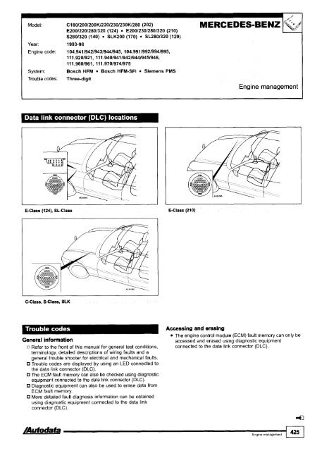
Model: C18012001200K122012301230K/280 (202) E200122012801320 (124) E200123012801320 (210) S2801320 (140) SLK200 (170) SL2801320 (129) Year: 1993-98 Engine code: 104.9411942194319441945, 104.991199219941995, 11 1.9201921, 11 1.9401941 1942194419451946, 111.9601961, 111.97019741975 System: Bosch HFM Bosch HFM-SF1 Siemens PMS Trouble codes: Three-digit MERCEDES-BEN2 Engine management C-Class, S-Class, SLK General information n Refer to the front of this manual for aeneral test conditions, terminology, detailed descriptions ofwiring faults and a general trouble shooter for electrical and mechanical faults. Trouble codes are displayed by using an LED connected to the data link connector (DLC). The ECM fault memory can also be checked using diagnostic equipment connected to the data link connector (DLC). Diagnostic equipment can also be used to erase data from ECM fault memory. More detailed fault diagnosis information can be obtained using diagnostic equipment connected to the data link connector (DLC). Accessing and erasing The engine control module (ECM) fault memory can only be accessed and erased usina " diaanostic eauioment v connected to the data link connector (DLC).'
-
Page 1 and 2:
Diagnostic Trouble Godes Fault loca
-
Page 3 and 4:
Contents This manual is a comprehen
-
Page 5 and 6:
-~ Engine management I Model Year S
-
Page 7 and 8:
Index 1 '. 4$ Engine management \&&
-
Page 9 and 10:
Index Engine management Year System
-
Page 11 and 12:
Index Engine management Model Year
-
Page 13 and 14:
Index Engine management Model Year
-
Page 15 and 16:
Index ,# '". '4 Engine management I
-
Page 17 and 18:
Model Year System page Laguna 2.0 1
-
Page 19 and 20:
m-p Engine management I 0;.6Q ) Mod
-
Page 21 and 22:
Engine management Model Year System
-
Page 23 and 24:
Engine management Y- ii f Model Yea
-
Page 25 and 26:
l Index Transmission ' :, A Model Y
-
Page 27 and 28:
1, / Index Immobilizer Model Year P
-
Page 29 and 30:
How to use this manual kmlh Kilomet
-
Page 31 and 32:
How to use this manual 1 number 1 I
-
Page 33 and 34:
How to use this manual Fig. 3 1 Hea
-
Page 35 and 36:
HOW to use this manual Check the fo
-
Page 37 and 38:
Tools & equipment The method of fau
-
Page 39 and 40:
Tools & equipment Resistance and co
-
Page 41 and 42:
Tools & equipment Breakout box - FI
-
Page 43 and 44:
Direct current (DC) voltage signals
-
Page 45 and 46:
Oscilloscope testing Frequency modu
-
Page 47 and 48:
Oscilloscope testing I Fig. 18 Fig.
-
Page 49 and 50:
Oscilloscope testing In alternating
-
Page 51 and 52:
Oxygen sensor (02s) NOTE: The follo
-
Page 53 and 54:
Trouble codes All the systems cover
-
Page 55 and 56:
Immobilizers The immobilizer may be
-
Page 57 and 58:
Trouble codes I Format of EOBD code
-
Page 59 and 60:
All EOBD codes starting with P zero
-
Page 61 and 62:
EOBD trouble code table PO057 PO058
-
Page 63 and 64:
EOBD trouble code table Trouble cod
-
Page 65 and 66:
1 :;:Ie Fautt Iocatiom PO161 Heated
-
Page 67 and 68:
I EOBD trouble code table - Trouble
-
Page 69 and 70:
EOBD trouble code table code PO290
-
Page 71 and 72:
EOBD trouble code table Trouble cod
-
Page 73 and 74:
~ - EOBD trouble code table code PO
-
Page 75 and 76:
EOBD trouble code table I lrouble c
-
Page 77 and 78:
EOBD trouble code table TrOub'e / R
-
Page 79 and 80:
EOBD trouble code table code PO630
-
Page 81 and 82:
EOBD trouble code table PO700 PO701
-
Page 83 and 84:
EOBD trouble code table Trouble cod
-
Page 85 and 86:
EOBD trouble code table PO838 PO839
-
Page 87 and 88:
EOBD trouble code table ( code TrOu
-
Page 89 and 90:
EOBD trouble code table PO948 PO949
-
Page 91 and 92:
Model: 1451146 1,411,611,812,O 1451
-
Page 93 and 94:
I Engine management I Fault locatio
-
Page 95 and 96:
Model. A2 A31S3 80 1,612,012,612,8
-
Page 97 and 98:
Model: A2 A363 80 1,612,012,612,8 8
-
Page 99 and 100:
Model: A2 A31S3 80 1,612,0/2,612,8
-
Page 101 and 102:
Model: A2 A31S3 80 1,612,012,6/2,8
-
Page 103 and 104:
Model: A2 A363 80 1,612,012,612,8 8
-
Page 105 and 106:
Model: A2 A363 80 1,6/2,012,6/2,8 8
-
Page 107 and 108:
Model: A2 A3lS3 80 1,6/2,012,6/2,8
-
Page 109 and 110:
Model: A2 A3lS3 80 1,612,012,612,8
-
Page 111 and 112:
Model: A2 A363 80 1,612,0/2,6/2,8 8
-
Page 113 and 114:
Model: A2 A363 80 1,6/2,012,6/2,8 8
-
Page 115 and 116:
Model: A2 A3lS3 80 1,6/2,012,612,8
-
Page 117 and 118:
Model: A2 A3lS3 80 1,6/2,012,6/2,8
-
Page 119 and 120:
Model: A2 A31S3 80 1,612,012,612,8
-
Page 121 and 122:
Model: A2 A3lS3 80 1,6/2,012,612,8
-
Page 123 and 124:
Model: A2 A31S3 80 1,612,012,612,8
-
Page 125 and 126:
Model: A2 A363 80 1,6/2,0/2,6/2,8 8
-
Page 127 and 128:
Model: A2 A3lS3 80 1,6/2,012,6/2,8
-
Page 129 and 130:
Model: A2 A3lS3 80 1,612,012,612,8
-
Page 131 and 132:
Model. 80 1,612,O 1001A6 2,O Engine
-
Page 133 and 134:
Model: Year: Engine code: System: A
-
Page 135 and 136:
I Model: 80 1,9 TDI (-06193) 100 2,
-
Page 137 and 138:
Engine management I type 4-digit Fa
-
Page 139 and 140:
Model: 80 2,O 16V 100 2,0 1001A6 2,
-
Page 141 and 142:
I Model 80 2,0 16V 100 2,0 1001A6 2
-
Page 143 and 144:
Engine management type 4-digit Faul
-
Page 145 and 146:
Engine management type 5-digit Faul
-
Page 147 and 148:
Model: A3 80 A4 100lA6 A61Allroad A
-
Page 149 and 150:
Model: A3 80 A4 1001A6 A6IAllroad A
-
Page 151 and 152:
Model: A3 80 A4 1001A6 A6IAllroad A
-
Page 153 and 154:
Model: A3 80 A4 100lA6 AGIAllroad A
-
Page 155 and 156:
Model: A2 A363 80 (08194 +) A41S4 A
-
Page 157 and 158:
Model: 316ilCompact, 318iliSICoupel
-
Page 159 and 160:
- Model: 316ilCompact, 318iliSICoup
-
Page 161 and 162:
I Model: 316ilCompact, 318iliSICoup
-
Page 163 and 164:
Model 316ilCornpact, 318iliSICoupel
-
Page 165 and 166:
Model: 325tdltds (E36) 525tdltds (E
-
Page 167 and 168:
Model: 3 SerieslCompact (E36) 3 Ser
-
Page 169 and 170:
Model: 3 SerieslCompact (E36) - 3 S
-
Page 171 and 172:
I I P I I Model: 3 SerieslCompact (
-
Page 173 and 174:
Model: 3 SerieslCompact (E36) 3 Ser
-
Page 175 and 176:
Model: 3 SerieslCompact (E36) 3 Ser
-
Page 177 and 178:
Model: 3 SerieslCompact (E36) 3 Ser
-
Page 179 and 180:
Model: 3 SerieslCompact (E36) 3 Ser
-
Page 181 and 182:
I Model: 3 Series (E36) 5 Series (E
-
Page 183 and 184:
Model: 3 Series (E36) 5 Series (E34
-
Page 185 and 186:
Model: Neon 2,O Stratus 2,O Stratus
-
Page 187 and 188:
* Model Neon 2,O Stratus 2,O Stratu
-
Page 189 and 190:
Model: Voyager 2,413,3/3,8 Grand Vo
-
Page 191 and 192:
Engine management Flash type Hex ty
-
Page 193 and 194:
Model: Voyager 2,4/3,3/3,8 Grand Vo
-
Page 195 and 196:
Model: Year: Engine code: System: V
-
Page 197 and 198:
Model: Voyager 2,4/3,3/3,8 Grand Vo
-
Page 199 and 200:
Engine management1 Hex type Fault l
-
Page 201 and 202:
Model: Voyager 2,4/3,3/3,8 Grand Vo
-
Page 203 and 204:
Model: Cherokee 2,514,O Grand Chero
-
Page 205 and 206:
Model: Cherokee 2,5/4,0 Grand Chero
-
Page 207 and 208:
Model. Cherokee 2,5/4,0 Grand Chero
-
Page 209 and 210:
Model: Cherokee 2,514,O Grand Chero
-
Page 211 and 212:
Model: Cherokee 2,5/4,0 Grand Chero
-
Page 213 and 214:
Model: Cherokee 2,514,O Grand Chero
-
Page 215 and 216:
Engine management/transmission AE A
-
Page 217 and 218:
Model: Cherokee 2,514.0 Grand Chero
-
Page 219 and 220:
Model: AX 1,011,111,4 C15 1,1/1,4 Z
-
Page 221 and 222:
Model: AX 1,011,111,4 C15 1,111,4 Z
-
Page 223 and 224:
Model: Saxo 1,011 ,I Berlingo 1,111
-
Page 225 and 226:
Model: Saxo 1,011,l Berlingo 1,111,
-
Page 227 and 228:
Model: Saxo 1,411,6 Berlingo 1,411,
-
Page 229 and 230:
Model: Saxo 1,4/1,6 Xsara 1 ,411,8
-
Page 231 and 232:
Model: Saxo 1,6 Year: 1996-98 Engin
-
Page 233 and 234:
I Engine Model: Saxo 1,6 Xsara 1,61
-
Page 235 and 236:
Model: Saxo 1,6 MT Xsara 1,6 Picass
-
Page 237 and 238:
7 Engine management EOBD type PI100
-
Page 239 and 240:
Model: Xsara 1,8 Engine management
-
Page 241 and 242:
Scanner type 10 11 12 13 14 15 16 1
-
Page 243 and 244:
P Model: Xsara 2,O Picasso 2,O C5 2
-
Page 245 and 246:
Model: Xsara 2,O HDi Xantia 2,O HDi
-
Page 247 and 248:
Model: Xantia 1,6/1,8 Xantia 2,0/Tu
-
Page 249 and 250:
7 Engine management Flash type FaW
-
Page 251 and 252:
I Engine management I Erasing Metho
-
Page 253 and 254:
Model: Xantia 2,lD Turbo XM 2,lD Tu
-
Page 255 and 256:
I Model: Cinquecento 90011 ,I Seice
-
Page 257 and 258:
,1 Seicento 90011,l Panda 9OOI1,l T
-
Page 259 and 260:
BravdBravo 1,2/1,4/1,8/2,0 MarealMa
-
Page 261 and 262:
OV/Turbo Fiorino 1,4/1,5/1,6 Genera
-
Page 263 and 264:
Model: Year: 1995-03 BravalBravo 1,
-
Page 265 and 266:
Year: 1994-04 Engine 'Ode: Ka 1,3 F
-
Page 267 and 268:
I Model: I Ka Fiesta EscorUOrion Fu
-
Page 269 and 270:
Model: Ka Fiesta EscorUOrion Fusion
-
Page 271 and 272:
Model: Ka Fiesta EscortlOrion Fusio
-
Page 273 and 274:
MondeolCougar urneo Connect gine ma
-
Page 275 and 276:
Model: Ka Fiesta EscortlOrion Fusio
-
Page 277 and 278:
scortlOrion Fusion Focus FocusC-MAX
-
Page 279 and 280:
Model: Ka Fiesta EscorVOrion Fusion
-
Page 281 and 282:
EOBD type -. Fault location Probabl
-
Page 283 and 284:
Model: Ka Fiesta EscortlOrion Fusio
-
Page 285 and 286:
EOBD type PI847 PI 848 PI849 PI850
-
Page 287 and 288:
Model: Ka Fiesta Escort/Orion Fusio
-
Page 289 and 290:
Fiesta 1,111,311, EscorVOrion 1,311
-
Page 291 and 292:
Model. Fiesta 1,111,311,411,6 Escor
-
Page 293 and 294:
Model: Escort 1,311,4 Year: 1995-96
-
Page 295 and 296:
Engine management/transmission lEl
-
Page 297 and 298:
Flash type I Fault location Probabl
-
Page 299 and 300:
Model: Fiesta 1,611,8 16V EscortlOr
-
Page 301 and 302:
Model: Fiesta l,6/l,8 16V EscorUOri
-
Page 303 and 304:
Model: Fiesta l,6/l,8 16V EscorVOri
-
Page 305 and 306:
Flash type Fault tocation Probable
-
Page 307 and 308:
I Engine managemenUtransrnission I
-
Page 309 and 310:
Model: Fiesta l,6/1,8 16V Escort l,
-
Page 311 and 312:
I Model: I Fiesta 1,611,8 16V Escor
-
Page 313 and 314:
Model: Escort RS 2000 Escort Coswor
-
Page 315 and 316:
Engine management/transmission h7 L
-
Page 317 and 318:
Erasing Ensure ignition switched OF
-
Page 319 and 320:
Model: Sierra 1,612,012,8 GranadalS
-
Page 321 and 322:
Engine management/transrnission ---
-
Page 323 and 324:
Model: Sierra 1,8 Sierra 2,9 V6 Gra
-
Page 325 and 326:
Model: Maverick 2,4 FORD Engine man
-
Page 327 and 328:
Engine management Erasing Ensure ig
-
Page 329 and 330:
Model: Transit 2,s D Turbo Engine m
-
Page 331 and 332:
d Model: Ka FiestalEscorVOrion Focu
-
Page 333 and 334:
Model: Civic 1,4/1,5/1,611,8 Civic
-
Page 335 and 336:
Civic Aerodeck 1,411,511,611, Troub
-
Page 337 and 338:
Model: Civic 1,4 Civic 1,6 Civic 2,
-
Page 339 and 340:
.- Model: Civic 1,4 Civic 1,6 Civic
-
Page 341 and 342:
I Model: Accord 1,812,012,2/2,3 Acc
-
Page 343 and 344:
Model: Accord 1,8/2,012,212,3 Accor
-
Page 345 and 346:
I Engine management I Trouble code
-
Page 347 and 348:
Model: CR-V 2,O CR-V 2,4 Year: 2002
-
Page 349 and 350:
Engine management/transmission 1 Ih
-
Page 351 and 352:
Engine code: F18A3, F2063, F20Z1, F
-
Page 353 and 354:
Model: Getz 1,111,3 Getz 1,511,6 DO
-
Page 355 and 356:
Model: Getz 1,1/1,3 Getz 1,5/1,6 DO
-
Page 357 and 358:
Model: Trooper 3,5 EOBD type Fault
-
Page 359 and 360:
Model: Trooper 3,s IsUzU Engine man
-
Page 361 and 362:
Model: XJ6 3,2/4,0 Sovereign 3,2/4,
-
Page 363 and 364:
I Model: XJ6 3,214,O Sovereign 3,21
-
Page 365 and 366:
I Model: Freelander 1,8 Freelander
-
Page 368 and 369:
LAND ROVER Model. I ~e.1 Engine man
-
Page 370 and 371:
MND ROVER Model: Freelander 1,8 Fre
-
Page 372 and 373:
Engine management Model: Discovery
-
Page 374 and 375:
1 374 I.,,,,,,,,, Autodata LAND ROV
-
Page 376 and 377:
1 376 I.,,,,,,,,,,,,, /Autodata LAN
-
Page 378 and 379:
Model: IS200 2,O IS300 $0 GS300 3,o
-
Page 380 and 381:
I LEXUS Model: IS200 2,O IS300 3,O
-
Page 382 and 383:
5 A - Engine managementltransmissio
-
Page 384 and 385:
EOBD type PI188 fault location ( Pr
-
Page 386 and 387:
Fl Engine managementltransmission E
-
Page 388 and 389:
Model: Mazda2 Mazda6 Tribute r i 1[
-
Page 390 and 391:
I/!'.,) , r- Engine managementltran
-
Page 392 and 393:
Model: Mazda2 Mazda6 Tribute 1 Engi
-
Page 394 and 395:
Model: Mazda2 Mazda6 Tribute I m"t-
-
Page 396 and 397:
1 31 Model: Mazda2 Mazda6 Tribute E
-
Page 398 and 399:
1 b- i' .I Engine management/transm
-
Page 400 and 401:
Model: Mazda2 Mazda6 Tribute '--- L
-
Page 402 and 403:
I MAZDA ~5.1 Year: 1989-03 323 (BG)
-
Page 404 and 405:
1 404 ................ MAZDA 1 b-->
-
Page 406 and 407:
, -' - MAZDA Model 323 (BG) 323 Est
-
Page 408 and 409:
I FJ,;-'; Engine managementltransmi
-
Page 410 and 411:
1 i, 5: .I Engine managementltransm
-
Page 412 and 413:
11 2 Engine managementltransmission
-
Page 414 and 415:
I-.,) Model: Engine management~tran
-
Page 416 and 417:
Model: 3231Estate 1,6 8VIl6V (BGIBW
-
Page 418 and 419:
Engine management Year: 1998-04 A1
-
Page 420 and 421:
I MERCEDES-BENZ Model: FEngine mana
-
Page 422 and 423:
ME RCED ESIBE NZ Model. Engine mana
-
Page 426 and 427:
I Engine management Trouble code id
-
Page 428 and 429:
ME RCEDES-BE NZ Model: C18012001200
-
Page 430 and 431:
ME RC ED ESIB E NZ I Engine managem
-
Page 432 and 433:
lMERCEDESIBE NZ Model: C180/200/200
-
Page 434 and 435:
CL42015001600 (140) SLK2OOl2OOW230W
-
Page 436 and 437:
M E RC E D ESIB E NZ Model C1801200
-
Page 438 and 439:
1 438 I,,,,,,,,,,, kJAutodata MERCE
-
Page 440 and 441:
Engine management Trouble code iden
-
Page 442 and 443:
I Engine management P type I Fault
-
Page 444 and 445:
I Engine management P type I Fau. l
-
Page 446 and 447:
I bJiil MERCEDES-BENZ Model. C-Clas
-
Page 448 and 449:
Model: C-Class (202) E-Class (124)
-
Page 450 and 451:
Engine management Model: One Cooper
-
Page 452 and 453:
fa J MINI Model: One Cooper Engine
-
Page 454 and 455:
I Engine management Model: One D Ye
-
Page 456 and 457:
Engine management Model: Galant 1,8
-
Page 458 and 459:
ITransrnission Model: Galant I Year
-
Page 460 and 461:
I ' I. !'1 MITSUBISHI Model: w Year
-
Page 462 and 463:
MITSUB1SH1 Model: Galant ShogunlPaj
-
Page 464 and 465:
Engine management Erasing Switch ig
-
Page 466 and 467:
Engine manayerrler luirarisrr~~ss~u
-
Page 468 and 469:
NISSAN Model: Sunny l,4/l,6/2,O Sun
-
Page 470 and 471:
- , I NISSAN Model: Almera l,5/l,8
-
Page 472 and 473:
Year: 2001 -04 Engine code: KA24E,
-
Page 474 and 475:
6' s Model: Almera l,5/l,8 Almera T
-
Page 476 and 477:
I r Y' NISSAN Model: Almera l,5/1,8
-
Page 478 and 479:
. I L Engine -- Flash type rnanagem
-
Page 480 and 481:
"&2" 2 -" , I-_ NlSSAN Model: Alrne
-
Page 482 and 483:
NISSAN Model: Almera 2,OD Primera 2
-
Page 484 and 485:
Model: Micra Alrnera Prirnera Seren
-
Page 486 and 487:
1 PEUGEOT Model: I06 1,011,111,311,
-
Page 488 and 489:
Erasing Method 2 Ensure ignition sw
-
Page 490 and 491:
Engine management Model: 106 1,011,
-
Page 492 and 493:
I PEUGEOT Model: 106 1,0/1,1/1,4/1,
-
Page 494 and 495:
?I PEUGEOT I Engine management Mode
-
Page 496 and 497:
Engine management Year: 2002-04 Eng
-
Page 498 and 499:
1 PEUGEOT Engine management Model:
-
Page 500 and 501:
1 PEUGEOT I Engine management Model
-
Page 502 and 503:
1 502 I,,,,,,,,,, Engine management
-
Page 504 and 505:
Model: 406 2,lD Turbo 605 2,lD Turb
-
Page 506 and 507:
PEUGEOT Model: 806 1,9D Turbo Year:
-
Page 508 and 509:
Model: R5Nan ExtralRapidlExpress Cl
-
Page 510 and 511:
RENAULT Model: RSNan ExtralRapidlEx
-
Page 512 and 513:
Clio - 4 997 Kangoo General informa
-
Page 514 and 515:
Model: Clio 1,2 Megane 2,O Kangoo 1
-
Page 516 and 517:
Model: Clio 1,SD Tur Fault lacatlon
-
Page 518 and 519:
-;'I RENAULT Model: Megane 1,411,61
-
Page 520 and 521:
,. 1:'
-
Page 522 and 523:
-, 1'. . + RENAULT Model: Megane 1,
-
Page 524 and 525:
,' ; i+ YJ RENAULT Model: Megane 1,
-
Page 526 and 527:
1';: v/I RENAULT 1 Engine managemen
-
Page 528 and 529:
I 528 I,,,,,,,, b'AUwata / -REhdAUL
-
Page 530 and 531:
I '1 RENAULT I Transmission Model:
-
Page 532 and 533:
Transmission Engine code: F3R 611,
-
Page 534 and 535:
1 Model: Clio 1,6 MeganelMegane Sce
-
Page 536 and 537:
I I_ , i I RENAULT Model: MeganelMe
-
Page 538 and 539:
RENAULT Model: ExtralRapidlExpress
-
Page 540 and 541:
Mini Metro1100 Montego 2001400 200
-
Page 542 and 543:
ROVER Model: Mini Metro1100 Montego
-
Page 544 and 545:
\ < / \ >d ; "L m ) I-_ ROVER Model
-
Page 546 and 547:
I 1 9- , ROVER Model: 2001CoupelCab
-
Page 548 and 549:
Engine management Model: 2001400/60
-
Page 550 and 551:
It>; Model: 20014001600 2,O TD I; /
-
Page 552 and 553:
N' i, - q~ - Engine management ' J
-
Page 554 and 555:
1 ROVER I Transmission Model: 600 2
-
Page 556 and 557:
It
-
Page 558 and 559:
1 558 I,,,,,,,,,, /Autodata I Engin
-
Page 560 and 561:
Engine management Model: 900 2,O Tu
-
Page 562 and 563:
I Engine management Model: 9-3 2,O
-
Page 564 and 565:
'I k4 ;c SUB Model: 9-3 2,O Turbo 9
-
Page 566 and 567:
1"; C jy SAAB Model: 9-3 2,O Turbo
-
Page 568 and 569:
Model: 9-3 2,2D Turbo (Engine manag
-
Page 570 and 571:
?, 'I vg SAAB Model: 9-3 2,2D Turbo
-
Page 572 and 573:
I'I.+. ,>I SAAB I Engine management
-
Page 574 and 575:
I Transmission Model: 900 9-3 9-5 E
-
Page 576 and 577:
Arosa lbizalcordoba 1,011,411,611,8
-
Page 578 and 579:
1 578 I,,,,,,,,,,, /Autodata Engine
-
Page 580 and 581:
I Engine management 5-digit type Fa
-
Page 582 and 583:
Engine management Probable cause 23
-
Page 584 and 585:
I Engine management Trouble code id
-
Page 586 and 587:
pJ M SEAT Model: Arosa IbizalCordob
-
Page 588 and 589:
1 / Model: Arosa IbizalCordoba Tole
-
Page 590 and 591:
Model: Favorit 1,3 Favorit VanlForm
-
Page 592 and 593:
IEngine management Erasing Method 1
-
Page 594 and 595:
Fabia FeliciaNanlPick-up Octavia 78
-
Page 596 and 597:
Year: Immobilizer Model: Fabia Feli
-
Page 598 and 599:
Engine management I Erasing NOTE: F
-
Page 600 and 601:
TOYOTA Model: Corolla 1,3 Corolla 1
-
Page 602 and 603:
I Engine management I Except 4A-GE
-
Page 604 and 605:
t- Engine management Model: Corolla
-
Page 606 and 607:
T OYOTA I Engine management Model:
-
Page 608 and 609:
TOYOTA Model: Carina 11 1,6 Carina
-
Page 610 and 611:
Model: Carina E 1,6/1,8/2,0 Carina
-
Page 612 and 613:
Model: Avensis 1,611,8/2,0 Avensis
-
Page 614 and 615:
Model: Avensis 1,611,812,O Avensis
-
Page 616 and 617:
I Engine management ON OFF 5 MA B A
-
Page 618 and 619:
Model: MR2 1,6 MR2 2,O 3s-FE13S-GE
-
Page 620 and 621:
Engine management I ~~~ A B A C A B
-
Page 622 and 623:
Model: Celica 1,6 Celica 1,8 Celica
-
Page 624 and 625:
1 TOYOTA Engine management Model: S
-
Page 626 and 627:
Located on main throttle butterfly
-
Page 628 and 629:
Model: Picnic 2,O Picnic 2,2D Turbo
-
Page 630 and 631:
TOYOTA Model: Previa 2,4 Year: 1990
-
Page 632 and 633:
I=a management Trouble code identif
-
Page 634 and 635:
Erasing NOTE: Fuse removal duration
-
Page 636 and 637:
Transmission Model: Carina E Year:
-
Page 638 and 639:
I Transmission Model: Year: Avensis
-
Page 640 and 641:
Transmission Model: Celica 2,O I 19
-
Page 642 and 643:
Transmission Model: Picnic Year: 19
-
Page 644 and 645:
d$i TEl(T) TSTC NOTE: Engine contro
-
Page 646 and 647:
Transmission Model: RAV4 Year: 1994
-
Page 648 and 649:
[I]- SOHC - engine bay, LH [2] - DO
-
Page 650 and 651:
Model: Corolla Year: 1995-01100 Und
-
Page 652 and 653:
Immobilizer Year: 1995-98 I General
-
Page 654 and 655:
Immobilizer Model: Avensis I Year:
-
Page 656 and 657:
RH engine bay General information R
-
Page 658 and 659:
T OWTA Model: Celica Year: 1995-99
-
Page 660 and 661:
General Information 0 Refer to the
-
Page 662 and 663:
. Model: Previa 1 Year: 1996-04100
-
Page 664 and 665:
General information Refer to the fr
-
Page 666 and 667:
VAUXHALL-OP E L Model: Agila 1,011,
-
Page 668 and 669:
EOBD type -. PI 551 PI 555 PI 560 E
-
Page 670 and 671:
Erasing NOTE: Some models 1992 -+ m
-
Page 672 and 673:
Vectra-B 1,611,8/2,2/2,512,6 Omega-
-
Page 674 and 675:
,* d VAU)(HALLIOPEL Model: /i7;e I
-
Page 676 and 677:
Omega-6 Zafira Erasing The engine c
-
Page 678 and 679:
VAU)(HALLIOPEL Model: I k ~f, .I En
-
Page 680 and 681:
VAuXHALLIOPEL Model: Corsa-C 1,7TD
-
Page 682 and 683:
I VAUXHALL-OPEL Model: AstraIKadett
-
Page 684 and 685:
FEngine management CarltonlOmega-B
-
Page 686 and 687:
VAUXHALL-OpEL Model: AstralKadett 2
-
Page 688 and 689:
VAUXHAf&oPEL Model: Astra-F 1,812,O
-
Page 690 and 691:
Engine management Year: 1997-04 Eng
-
Page 692 and 693:
Omega-B 2,OTD12,2TD Zafira 2,OTD12,
-
Page 694 and 695:
VAUXHALL-OPEL Model: Astra-G 1.7 TD
-
Page 696 and 697:
EOBD type / Fault hat1011 Probable
-
Page 698 and 699:
VAUXHALL-OPEL Model Astra-G 2,2 Spe
-
Page 700 and 701:
Engine management Year: 1994-00 I E
-
Page 702 and 703:
Engine management Flash'scanner Fau
-
Page 704 and 705:
Trouble code identification EOBD ty
-
Page 706 and 707:
VAUXHALL-OPEL Model: Vectra-C 1,6 F
-
Page 708 and 709:
VAUXHALL-OPEL Model: Vectra-C 1,6 F
-
Page 710 and 711:
I I 1% VAUXHALL-OPEL Mode I Transmi
-
Page 712 and 713:
VAUXHALL-OPEL Model Corsa-BTTigra A
-
Page 714 and 715:
Year: Transmission 1995-98 General
-
Page 716 and 717:
I Year: 1994-97 Transmission Genera
-
Page 718 and 719:
I I VAUXHALL-OPEL ~odel: Immobilize
-
Page 720 and 721:
1-41 IVAuXHALL-OPEL Yodel: Zafira C
-
Page 722 and 723:
VOLKSWAGEN Model: Lupo Polo 1,3 Pol
-
Page 724 and 725:
Engine management Model: Lupo Polo
-
Page 726 and 727:
Engine management Model: Lupo Polo
-
Page 728 and 729:
VOLKSWAGEN Model Lupo Polo 1,3 Polo
-
Page 730 and 731:
VOLKSWAGEN Model: Lupo Polo 1,3 Pol
-
Page 732 and 733:
Model: ~upo polo 1,3 PololClassiclE
-
Page 734 and 735:
VOLKSWAGEN Model Lupo Polo 1,3 Polo
-
Page 736 and 737:
VOLKSWAGEN Model: Lupo Polo 1,3 Pol
-
Page 738 and 739:
Engine management Model. Lupo Polo
-
Page 740 and 741:
I VOLKSWAGEN Model: Lupo Polo 1,3 P
-
Page 742 and 743:
VOLKSWAGEN Model: Lupo Polo 1,3 Pol
-
Page 744 and 745:
1 744 I,.,,,,,,,, /AUfodata I Engin
-
Page 746 and 747:
Engine management Model: Lupo Polo
-
Page 748 and 749:
Engine management Model: Lupo Polo
-
Page 750 and 751:
VOLKSWAGEN Model: Lupo Polo 1,3 Pol
-
Page 752 and 753:
Engine management Model: Lupo Polo
-
Page 754 and 755:
I Model: Lupo Polo 1,3 PololClassic
-
Page 756 and 757:
1 756 I,,,.,,,.,,, /Autodata VOLKSW
-
Page 758 and 759:
1 I,,,,,,,,,, 758 /Autodata F e man
-
Page 760 and 761:
I Engine management Erasing Method
-
Page 762 and 763:
1 762 I,,,,,,,,,,,, /Autodata - J V
-
Page 764 and 765:
1 VOLKSWAGEN Model: Polo 1 ,O5/l,3
-
Page 766 and 767:
VOLKSWAGEN Model: GolfNento 1,4 (-0
-
Page 768 and 769:
VOLKSWAGEN Model: GolfNento 1,4 (+0
-
Page 770 and 771:
Erasing Ensure ignition switched OF
-
Page 772 and 773:
Engine management Engine code: Syst
-
Page 775 and 776:
I Year: 03\95-96 I Engine code: 1E
-
Page 777 and 778:
4 Model: Lupo PololClassiclEstate G
-
Page 779 and 780:
Trouble code identification VAG typ
-
Page 781 and 782:
Model: Lupo PololClassiclEstate Gol
-
Page 783 and 784:
Model: Lupo PololClassiclEstate Gol
-
Page 785 and 786:
General information Refer to the fr
-
Page 787 and 788:
:-$yp"' 00545 00596 00638 00641 006
-
Page 789 and 790:
Beetle Passat Corrado (10194-95) Sh
-
Page 791 and 792:
CaddyIPickup TransporterICaravelle
-
Page 793 and 794:
Mel: 440/460/ VOLVO Engine manageme
-
Page 795 and 796:
Trouble code identification Scanner
-
Page 797 and 798:
EFI-355 EFI-411 EFI-414 EFI-415 EFI
-
Page 799 and 800:
Model: SN40 1,6/1,8/1,9/2,0 SN40 1,
-
Page 801 and 802:
V70 2,4ITurbo C70 2,O Turbo C70 2,3
-
Page 803 and 804:
Model: S60 2,012,3 Turbo S60 2,4lTu
-
Page 805 and 806:
I I Model: S60 2,012,3 Turbo S60 2,
-
Page 807 and 808:
Model: 240 2,012,3 740 2,012,3 7401
-
Page 809 and 810:
940 2,OITurbo 9401960 2,0/2,3ITurbo
-
Page 811 and 812:
I Engine management Erasing Ensure
-
Page 813 and 814:
Model: 850 2,O 850 2,3/2,5 850 2,5
-
Page 815 and 816:
Model: 850 2,O 850 2,312,5 850 2,5
-
Page 817 and 818:
Model: 850 2,O 850 2,3/2,5 850 2,5
-
Page 819 and 820:
Flash type Fault location Probable
-
Page 821 and 822:
Engine management I Ignition system
-
Page 823 and 824:
Model: 850 2,012,5 9401960 2,0/2,3/
-
Page 825 and 826:
1 Transmission Erasing Ensure ignit
-
Page 827 and 828:
I Year: 'i Transmission - 850 - nea
-
Page 829 and 830:
Model: 850 SNIC7O 960 Scanner ty Pe
-
Page 831 and 832:
Model: SN40 850 SNIC70 9401960 voLv