- Page 1 and 2: Diagnostic Trouble Godes Fault loca
- Page 3 and 4: Contents This manual is a comprehen
- Page 5 and 6: -~ Engine management I Model Year S
- Page 7 and 8: Index 1 '. 4$ Engine management \&&
- Page 9 and 10: Index Engine management Year System
- Page 11 and 12: Index Engine management Model Year
- Page 13 and 14: Index Engine management Model Year
- Page 15 and 16: Index ,# '". '4 Engine management I
- Page 17 and 18: Model Year System page Laguna 2.0 1
- Page 19 and 20: m-p Engine management I 0;.6Q ) Mod
- Page 21 and 22: Engine management Model Year System
- Page 23 and 24: Engine management Y- ii f Model Yea
- Page 25 and 26: l Index Transmission ' :, A Model Y
- Page 27 and 28: 1, / Index Immobilizer Model Year P
- Page 29 and 30: How to use this manual kmlh Kilomet
- Page 31 and 32: How to use this manual 1 number 1 I
- Page 33 and 34: How to use this manual Fig. 3 1 Hea
- Page 35 and 36: HOW to use this manual Check the fo
- Page 37 and 38: Tools & equipment The method of fau
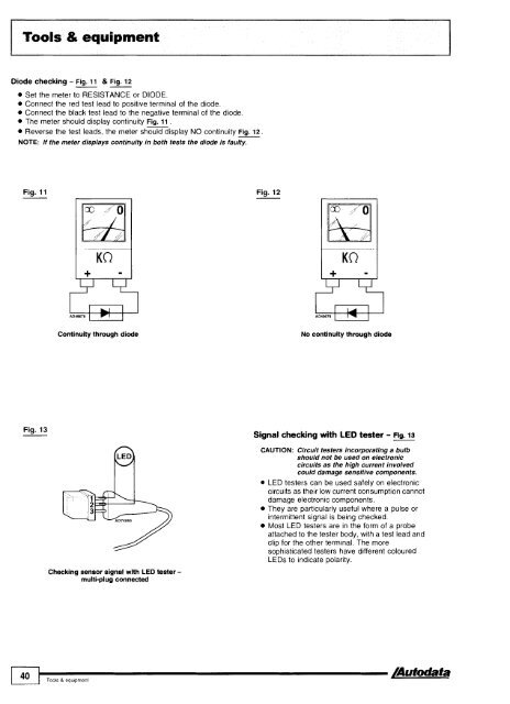
- Page 39: Tools & equipment Resistance and co
- Page 43 and 44: Direct current (DC) voltage signals
- Page 45 and 46: Oscilloscope testing Frequency modu
- Page 47 and 48: Oscilloscope testing I Fig. 18 Fig.
- Page 49 and 50: Oscilloscope testing In alternating
- Page 51 and 52: Oxygen sensor (02s) NOTE: The follo
- Page 53 and 54: Trouble codes All the systems cover
- Page 55 and 56: Immobilizers The immobilizer may be
- Page 57 and 58: Trouble codes I Format of EOBD code
- Page 59 and 60: All EOBD codes starting with P zero
- Page 61 and 62: EOBD trouble code table PO057 PO058
- Page 63 and 64: EOBD trouble code table Trouble cod
- Page 65 and 66: 1 :;:Ie Fautt Iocatiom PO161 Heated
- Page 67 and 68: I EOBD trouble code table - Trouble
- Page 69 and 70: EOBD trouble code table code PO290
- Page 71 and 72: EOBD trouble code table Trouble cod
- Page 73 and 74: ~ - EOBD trouble code table code PO
- Page 75 and 76: EOBD trouble code table I lrouble c
- Page 77 and 78: EOBD trouble code table TrOub'e / R
- Page 79 and 80: EOBD trouble code table code PO630
- Page 81 and 82: EOBD trouble code table PO700 PO701
- Page 83 and 84: EOBD trouble code table Trouble cod
- Page 85 and 86: EOBD trouble code table PO838 PO839
- Page 87 and 88: EOBD trouble code table ( code TrOu
- Page 89 and 90: EOBD trouble code table PO948 PO949
- Page 91 and 92:
Model: 1451146 1,411,611,812,O 1451
- Page 93 and 94:
I Engine management I Fault locatio
- Page 95 and 96:
Model. A2 A31S3 80 1,612,012,612,8
- Page 97 and 98:
Model: A2 A363 80 1,612,012,612,8 8
- Page 99 and 100:
Model: A2 A31S3 80 1,612,0/2,612,8
- Page 101 and 102:
Model: A2 A31S3 80 1,612,012,6/2,8
- Page 103 and 104:
Model: A2 A363 80 1,612,012,612,8 8
- Page 105 and 106:
Model: A2 A363 80 1,6/2,012,6/2,8 8
- Page 107 and 108:
Model: A2 A3lS3 80 1,6/2,012,6/2,8
- Page 109 and 110:
Model: A2 A3lS3 80 1,612,012,612,8
- Page 111 and 112:
Model: A2 A363 80 1,612,0/2,6/2,8 8
- Page 113 and 114:
Model: A2 A363 80 1,6/2,012,6/2,8 8
- Page 115 and 116:
Model: A2 A3lS3 80 1,6/2,012,612,8
- Page 117 and 118:
Model: A2 A3lS3 80 1,6/2,012,6/2,8
- Page 119 and 120:
Model: A2 A31S3 80 1,612,012,612,8
- Page 121 and 122:
Model: A2 A3lS3 80 1,6/2,012,612,8
- Page 123 and 124:
Model: A2 A31S3 80 1,612,012,612,8
- Page 125 and 126:
Model: A2 A363 80 1,6/2,0/2,6/2,8 8
- Page 127 and 128:
Model: A2 A3lS3 80 1,6/2,012,6/2,8
- Page 129 and 130:
Model: A2 A3lS3 80 1,612,012,612,8
- Page 131 and 132:
Model. 80 1,612,O 1001A6 2,O Engine
- Page 133 and 134:
Model: Year: Engine code: System: A
- Page 135 and 136:
I Model: 80 1,9 TDI (-06193) 100 2,
- Page 137 and 138:
Engine management I type 4-digit Fa
- Page 139 and 140:
Model: 80 2,O 16V 100 2,0 1001A6 2,
- Page 141 and 142:
I Model 80 2,0 16V 100 2,0 1001A6 2
- Page 143 and 144:
Engine management type 4-digit Faul
- Page 145 and 146:
Engine management type 5-digit Faul
- Page 147 and 148:
Model: A3 80 A4 100lA6 A61Allroad A
- Page 149 and 150:
Model: A3 80 A4 1001A6 A6IAllroad A
- Page 151 and 152:
Model: A3 80 A4 1001A6 A6IAllroad A
- Page 153 and 154:
Model: A3 80 A4 100lA6 AGIAllroad A
- Page 155 and 156:
Model: A2 A363 80 (08194 +) A41S4 A
- Page 157 and 158:
Model: 316ilCompact, 318iliSICoupel
- Page 159 and 160:
- Model: 316ilCompact, 318iliSICoup
- Page 161 and 162:
I Model: 316ilCompact, 318iliSICoup
- Page 163 and 164:
Model 316ilCornpact, 318iliSICoupel
- Page 165 and 166:
Model: 325tdltds (E36) 525tdltds (E
- Page 167 and 168:
Model: 3 SerieslCompact (E36) 3 Ser
- Page 169 and 170:
Model: 3 SerieslCompact (E36) - 3 S
- Page 171 and 172:
I I P I I Model: 3 SerieslCompact (
- Page 173 and 174:
Model: 3 SerieslCompact (E36) 3 Ser
- Page 175 and 176:
Model: 3 SerieslCompact (E36) 3 Ser
- Page 177 and 178:
Model: 3 SerieslCompact (E36) 3 Ser
- Page 179 and 180:
Model: 3 SerieslCompact (E36) 3 Ser
- Page 181 and 182:
I Model: 3 Series (E36) 5 Series (E
- Page 183 and 184:
Model: 3 Series (E36) 5 Series (E34
- Page 185 and 186:
Model: Neon 2,O Stratus 2,O Stratus
- Page 187 and 188:
* Model Neon 2,O Stratus 2,O Stratu
- Page 189 and 190:
Model: Voyager 2,413,3/3,8 Grand Vo
- Page 191 and 192:
Engine management Flash type Hex ty
- Page 193 and 194:
Model: Voyager 2,4/3,3/3,8 Grand Vo
- Page 195 and 196:
Model: Year: Engine code: System: V
- Page 197 and 198:
Model: Voyager 2,4/3,3/3,8 Grand Vo
- Page 199 and 200:
Engine management1 Hex type Fault l
- Page 201 and 202:
Model: Voyager 2,4/3,3/3,8 Grand Vo
- Page 203 and 204:
Model: Cherokee 2,514,O Grand Chero
- Page 205 and 206:
Model: Cherokee 2,5/4,0 Grand Chero
- Page 207 and 208:
Model. Cherokee 2,5/4,0 Grand Chero
- Page 209 and 210:
Model: Cherokee 2,514,O Grand Chero
- Page 211 and 212:
Model: Cherokee 2,5/4,0 Grand Chero
- Page 213 and 214:
Model: Cherokee 2,514,O Grand Chero
- Page 215 and 216:
Engine management/transmission AE A
- Page 217 and 218:
Model: Cherokee 2,514.0 Grand Chero
- Page 219 and 220:
Model: AX 1,011,111,4 C15 1,1/1,4 Z
- Page 221 and 222:
Model: AX 1,011,111,4 C15 1,111,4 Z
- Page 223 and 224:
Model: Saxo 1,011 ,I Berlingo 1,111
- Page 225 and 226:
Model: Saxo 1,011,l Berlingo 1,111,
- Page 227 and 228:
Model: Saxo 1,411,6 Berlingo 1,411,
- Page 229 and 230:
Model: Saxo 1,4/1,6 Xsara 1 ,411,8
- Page 231 and 232:
Model: Saxo 1,6 Year: 1996-98 Engin
- Page 233 and 234:
I Engine Model: Saxo 1,6 Xsara 1,61
- Page 235 and 236:
Model: Saxo 1,6 MT Xsara 1,6 Picass
- Page 237 and 238:
7 Engine management EOBD type PI100
- Page 239 and 240:
Model: Xsara 1,8 Engine management
- Page 241 and 242:
Scanner type 10 11 12 13 14 15 16 1
- Page 243 and 244:
P Model: Xsara 2,O Picasso 2,O C5 2
- Page 245 and 246:
Model: Xsara 2,O HDi Xantia 2,O HDi
- Page 247 and 248:
Model: Xantia 1,6/1,8 Xantia 2,0/Tu
- Page 249 and 250:
7 Engine management Flash type FaW
- Page 251 and 252:
I Engine management I Erasing Metho
- Page 253 and 254:
Model: Xantia 2,lD Turbo XM 2,lD Tu
- Page 255 and 256:
I Model: Cinquecento 90011 ,I Seice
- Page 257 and 258:
,1 Seicento 90011,l Panda 9OOI1,l T
- Page 259 and 260:
BravdBravo 1,2/1,4/1,8/2,0 MarealMa
- Page 261 and 262:
OV/Turbo Fiorino 1,4/1,5/1,6 Genera
- Page 263 and 264:
Model: Year: 1995-03 BravalBravo 1,
- Page 265 and 266:
Year: 1994-04 Engine 'Ode: Ka 1,3 F
- Page 267 and 268:
I Model: I Ka Fiesta EscorUOrion Fu
- Page 269 and 270:
Model: Ka Fiesta EscorUOrion Fusion
- Page 271 and 272:
Model: Ka Fiesta EscortlOrion Fusio
- Page 273 and 274:
MondeolCougar urneo Connect gine ma
- Page 275 and 276:
Model: Ka Fiesta EscortlOrion Fusio
- Page 277 and 278:
scortlOrion Fusion Focus FocusC-MAX
- Page 279 and 280:
Model: Ka Fiesta EscorVOrion Fusion
- Page 281 and 282:
EOBD type -. Fault location Probabl
- Page 283 and 284:
Model: Ka Fiesta EscortlOrion Fusio
- Page 285 and 286:
EOBD type PI847 PI 848 PI849 PI850
- Page 287 and 288:
Model: Ka Fiesta Escort/Orion Fusio
- Page 289 and 290:
Fiesta 1,111,311, EscorVOrion 1,311
- Page 291 and 292:
Model. Fiesta 1,111,311,411,6 Escor
- Page 293 and 294:
Model: Escort 1,311,4 Year: 1995-96
- Page 295 and 296:
Engine management/transmission lEl
- Page 297 and 298:
Flash type I Fault location Probabl
- Page 299 and 300:
Model: Fiesta 1,611,8 16V EscortlOr
- Page 301 and 302:
Model: Fiesta l,6/l,8 16V EscorUOri
- Page 303 and 304:
Model: Fiesta l,6/l,8 16V EscorVOri
- Page 305 and 306:
Flash type Fault tocation Probable
- Page 307 and 308:
I Engine managemenUtransrnission I
- Page 309 and 310:
Model: Fiesta l,6/1,8 16V Escort l,
- Page 311 and 312:
I Model: I Fiesta 1,611,8 16V Escor
- Page 313 and 314:
Model: Escort RS 2000 Escort Coswor
- Page 315 and 316:
Engine management/transmission h7 L
- Page 317 and 318:
Erasing Ensure ignition switched OF
- Page 319 and 320:
Model: Sierra 1,612,012,8 GranadalS
- Page 321 and 322:
Engine management/transrnission ---
- Page 323 and 324:
Model: Sierra 1,8 Sierra 2,9 V6 Gra
- Page 325 and 326:
Model: Maverick 2,4 FORD Engine man
- Page 327 and 328:
Engine management Erasing Ensure ig
- Page 329 and 330:
Model: Transit 2,s D Turbo Engine m
- Page 331 and 332:
d Model: Ka FiestalEscorVOrion Focu
- Page 333 and 334:
Model: Civic 1,4/1,5/1,611,8 Civic
- Page 335 and 336:
Civic Aerodeck 1,411,511,611, Troub
- Page 337 and 338:
Model: Civic 1,4 Civic 1,6 Civic 2,
- Page 339 and 340:
.- Model: Civic 1,4 Civic 1,6 Civic
- Page 341 and 342:
I Model: Accord 1,812,012,2/2,3 Acc
- Page 343 and 344:
Model: Accord 1,8/2,012,212,3 Accor
- Page 345 and 346:
I Engine management I Trouble code
- Page 347 and 348:
Model: CR-V 2,O CR-V 2,4 Year: 2002
- Page 349 and 350:
Engine management/transmission 1 Ih
- Page 351 and 352:
Engine code: F18A3, F2063, F20Z1, F
- Page 353 and 354:
Model: Getz 1,111,3 Getz 1,511,6 DO
- Page 355 and 356:
Model: Getz 1,1/1,3 Getz 1,5/1,6 DO
- Page 357 and 358:
Model: Trooper 3,5 EOBD type Fault
- Page 359 and 360:
Model: Trooper 3,s IsUzU Engine man
- Page 361 and 362:
Model: XJ6 3,2/4,0 Sovereign 3,2/4,
- Page 363 and 364:
I Model: XJ6 3,214,O Sovereign 3,21
- Page 365 and 366:
I Model: Freelander 1,8 Freelander
- Page 368 and 369:
LAND ROVER Model. I ~e.1 Engine man
- Page 370 and 371:
MND ROVER Model: Freelander 1,8 Fre
- Page 372 and 373:
Engine management Model: Discovery
- Page 374 and 375:
1 374 I.,,,,,,,,, Autodata LAND ROV
- Page 376 and 377:
1 376 I.,,,,,,,,,,,,, /Autodata LAN
- Page 378 and 379:
Model: IS200 2,O IS300 $0 GS300 3,o
- Page 380 and 381:
I LEXUS Model: IS200 2,O IS300 3,O
- Page 382 and 383:
5 A - Engine managementltransmissio
- Page 384 and 385:
EOBD type PI188 fault location ( Pr
- Page 386 and 387:
Fl Engine managementltransmission E
- Page 388 and 389:
Model: Mazda2 Mazda6 Tribute r i 1[
- Page 390 and 391:
I/!'.,) , r- Engine managementltran
- Page 392 and 393:
Model: Mazda2 Mazda6 Tribute 1 Engi
- Page 394 and 395:
Model: Mazda2 Mazda6 Tribute I m"t-
- Page 396 and 397:
1 31 Model: Mazda2 Mazda6 Tribute E
- Page 398 and 399:
1 b- i' .I Engine management/transm
- Page 400 and 401:
Model: Mazda2 Mazda6 Tribute '--- L
- Page 402 and 403:
I MAZDA ~5.1 Year: 1989-03 323 (BG)
- Page 404 and 405:
1 404 ................ MAZDA 1 b-->
- Page 406 and 407:
, -' - MAZDA Model 323 (BG) 323 Est
- Page 408 and 409:
I FJ,;-'; Engine managementltransmi
- Page 410 and 411:
1 i, 5: .I Engine managementltransm
- Page 412 and 413:
11 2 Engine managementltransmission
- Page 414 and 415:
I-.,) Model: Engine management~tran
- Page 416 and 417:
Model: 3231Estate 1,6 8VIl6V (BGIBW
- Page 418 and 419:
Engine management Year: 1998-04 A1
- Page 420 and 421:
I MERCEDES-BENZ Model: FEngine mana
- Page 422 and 423:
ME RCED ESIBE NZ Model. Engine mana
- Page 424 and 425:
1 424 I,,,.,,,,,,, IAutodata ME RCE
- Page 426 and 427:
I Engine management Trouble code id
- Page 428 and 429:
ME RCEDES-BE NZ Model: C18012001200
- Page 430 and 431:
ME RC ED ESIB E NZ I Engine managem
- Page 432 and 433:
lMERCEDESIBE NZ Model: C180/200/200
- Page 434 and 435:
CL42015001600 (140) SLK2OOl2OOW230W
- Page 436 and 437:
M E RC E D ESIB E NZ Model C1801200
- Page 438 and 439:
1 438 I,,,,,,,,,,, kJAutodata MERCE
- Page 440 and 441:
Engine management Trouble code iden
- Page 442 and 443:
I Engine management P type I Fault
- Page 444 and 445:
I Engine management P type I Fau. l
- Page 446 and 447:
I bJiil MERCEDES-BENZ Model. C-Clas
- Page 448 and 449:
Model: C-Class (202) E-Class (124)
- Page 450 and 451:
Engine management Model: One Cooper
- Page 452 and 453:
fa J MINI Model: One Cooper Engine
- Page 454 and 455:
I Engine management Model: One D Ye
- Page 456 and 457:
Engine management Model: Galant 1,8
- Page 458 and 459:
ITransrnission Model: Galant I Year
- Page 460 and 461:
I ' I. !'1 MITSUBISHI Model: w Year
- Page 462 and 463:
MITSUB1SH1 Model: Galant ShogunlPaj
- Page 464 and 465:
Engine management Erasing Switch ig
- Page 466 and 467:
Engine manayerrler luirarisrr~~ss~u
- Page 468 and 469:
NISSAN Model: Sunny l,4/l,6/2,O Sun
- Page 470 and 471:
- , I NISSAN Model: Almera l,5/l,8
- Page 472 and 473:
Year: 2001 -04 Engine code: KA24E,
- Page 474 and 475:
6' s Model: Almera l,5/l,8 Almera T
- Page 476 and 477:
I r Y' NISSAN Model: Almera l,5/1,8
- Page 478 and 479:
. I L Engine -- Flash type rnanagem
- Page 480 and 481:
"&2" 2 -" , I-_ NlSSAN Model: Alrne
- Page 482 and 483:
NISSAN Model: Almera 2,OD Primera 2
- Page 484 and 485:
Model: Micra Alrnera Prirnera Seren
- Page 486 and 487:
1 PEUGEOT Model: I06 1,011,111,311,
- Page 488 and 489:
Erasing Method 2 Ensure ignition sw
- Page 490 and 491:
Engine management Model: 106 1,011,
- Page 492 and 493:
I PEUGEOT Model: 106 1,0/1,1/1,4/1,
- Page 494 and 495:
?I PEUGEOT I Engine management Mode
- Page 496 and 497:
Engine management Year: 2002-04 Eng
- Page 498 and 499:
1 PEUGEOT Engine management Model:
- Page 500 and 501:
1 PEUGEOT I Engine management Model
- Page 502 and 503:
1 502 I,,,,,,,,,, Engine management
- Page 504 and 505:
Model: 406 2,lD Turbo 605 2,lD Turb
- Page 506 and 507:
PEUGEOT Model: 806 1,9D Turbo Year:
- Page 508 and 509:
Model: R5Nan ExtralRapidlExpress Cl
- Page 510 and 511:
RENAULT Model: RSNan ExtralRapidlEx
- Page 512 and 513:
Clio - 4 997 Kangoo General informa
- Page 514 and 515:
Model: Clio 1,2 Megane 2,O Kangoo 1
- Page 516 and 517:
Model: Clio 1,SD Tur Fault lacatlon
- Page 518 and 519:
-;'I RENAULT Model: Megane 1,411,61
- Page 520 and 521:
,. 1:'
- Page 522 and 523:
-, 1'. . + RENAULT Model: Megane 1,
- Page 524 and 525:
,' ; i+ YJ RENAULT Model: Megane 1,
- Page 526 and 527:
1';: v/I RENAULT 1 Engine managemen
- Page 528 and 529:
I 528 I,,,,,,,, b'AUwata / -REhdAUL
- Page 530 and 531:
I '1 RENAULT I Transmission Model:
- Page 532 and 533:
Transmission Engine code: F3R 611,
- Page 534 and 535:
1 Model: Clio 1,6 MeganelMegane Sce
- Page 536 and 537:
I I_ , i I RENAULT Model: MeganelMe
- Page 538 and 539:
RENAULT Model: ExtralRapidlExpress
- Page 540 and 541:
Mini Metro1100 Montego 2001400 200
- Page 542 and 543:
ROVER Model: Mini Metro1100 Montego
- Page 544 and 545:
\ < / \ >d ; "L m ) I-_ ROVER Model
- Page 546 and 547:
I 1 9- , ROVER Model: 2001CoupelCab
- Page 548 and 549:
Engine management Model: 2001400/60
- Page 550 and 551:
It>; Model: 20014001600 2,O TD I; /
- Page 552 and 553:
N' i, - q~ - Engine management ' J
- Page 554 and 555:
1 ROVER I Transmission Model: 600 2
- Page 556 and 557:
It
- Page 558 and 559:
1 558 I,,,,,,,,,, /Autodata I Engin
- Page 560 and 561:
Engine management Model: 900 2,O Tu
- Page 562 and 563:
I Engine management Model: 9-3 2,O
- Page 564 and 565:
'I k4 ;c SUB Model: 9-3 2,O Turbo 9
- Page 566 and 567:
1"; C jy SAAB Model: 9-3 2,O Turbo
- Page 568 and 569:
Model: 9-3 2,2D Turbo (Engine manag
- Page 570 and 571:
?, 'I vg SAAB Model: 9-3 2,2D Turbo
- Page 572 and 573:
I'I.+. ,>I SAAB I Engine management
- Page 574 and 575:
I Transmission Model: 900 9-3 9-5 E
- Page 576 and 577:
Arosa lbizalcordoba 1,011,411,611,8
- Page 578 and 579:
1 578 I,,,,,,,,,,, /Autodata Engine
- Page 580 and 581:
I Engine management 5-digit type Fa
- Page 582 and 583:
Engine management Probable cause 23
- Page 584 and 585:
I Engine management Trouble code id
- Page 586 and 587:
pJ M SEAT Model: Arosa IbizalCordob
- Page 588 and 589:
1 / Model: Arosa IbizalCordoba Tole
- Page 590 and 591:
Model: Favorit 1,3 Favorit VanlForm
- Page 592 and 593:
IEngine management Erasing Method 1
- Page 594 and 595:
Fabia FeliciaNanlPick-up Octavia 78
- Page 596 and 597:
Year: Immobilizer Model: Fabia Feli
- Page 598 and 599:
Engine management I Erasing NOTE: F
- Page 600 and 601:
TOYOTA Model: Corolla 1,3 Corolla 1
- Page 602 and 603:
I Engine management I Except 4A-GE
- Page 604 and 605:
t- Engine management Model: Corolla
- Page 606 and 607:
T OYOTA I Engine management Model:
- Page 608 and 609:
TOYOTA Model: Carina 11 1,6 Carina
- Page 610 and 611:
Model: Carina E 1,6/1,8/2,0 Carina
- Page 612 and 613:
Model: Avensis 1,611,8/2,0 Avensis
- Page 614 and 615:
Model: Avensis 1,611,812,O Avensis
- Page 616 and 617:
I Engine management ON OFF 5 MA B A
- Page 618 and 619:
Model: MR2 1,6 MR2 2,O 3s-FE13S-GE
- Page 620 and 621:
Engine management I ~~~ A B A C A B
- Page 622 and 623:
Model: Celica 1,6 Celica 1,8 Celica
- Page 624 and 625:
1 TOYOTA Engine management Model: S
- Page 626 and 627:
Located on main throttle butterfly
- Page 628 and 629:
Model: Picnic 2,O Picnic 2,2D Turbo
- Page 630 and 631:
TOYOTA Model: Previa 2,4 Year: 1990
- Page 632 and 633:
I=a management Trouble code identif
- Page 634 and 635:
Erasing NOTE: Fuse removal duration
- Page 636 and 637:
Transmission Model: Carina E Year:
- Page 638 and 639:
I Transmission Model: Year: Avensis
- Page 640 and 641:
Transmission Model: Celica 2,O I 19
- Page 642 and 643:
Transmission Model: Picnic Year: 19
- Page 644 and 645:
d$i TEl(T) TSTC NOTE: Engine contro
- Page 646 and 647:
Transmission Model: RAV4 Year: 1994
- Page 648 and 649:
[I]- SOHC - engine bay, LH [2] - DO
- Page 650 and 651:
Model: Corolla Year: 1995-01100 Und
- Page 652 and 653:
Immobilizer Year: 1995-98 I General
- Page 654 and 655:
Immobilizer Model: Avensis I Year:
- Page 656 and 657:
RH engine bay General information R
- Page 658 and 659:
T OWTA Model: Celica Year: 1995-99
- Page 660 and 661:
General Information 0 Refer to the
- Page 662 and 663:
. Model: Previa 1 Year: 1996-04100
- Page 664 and 665:
General information Refer to the fr
- Page 666 and 667:
VAUXHALL-OP E L Model: Agila 1,011,
- Page 668 and 669:
EOBD type -. PI 551 PI 555 PI 560 E
- Page 670 and 671:
Erasing NOTE: Some models 1992 -+ m
- Page 672 and 673:
Vectra-B 1,611,8/2,2/2,512,6 Omega-
- Page 674 and 675:
,* d VAU)(HALLIOPEL Model: /i7;e I
- Page 676 and 677:
Omega-6 Zafira Erasing The engine c
- Page 678 and 679:
VAU)(HALLIOPEL Model: I k ~f, .I En
- Page 680 and 681:
VAuXHALLIOPEL Model: Corsa-C 1,7TD
- Page 682 and 683:
I VAUXHALL-OPEL Model: AstraIKadett
- Page 684 and 685:
FEngine management CarltonlOmega-B
- Page 686 and 687:
VAUXHALL-OpEL Model: AstralKadett 2
- Page 688 and 689:
VAUXHAf&oPEL Model: Astra-F 1,812,O
- Page 690 and 691:
Engine management Year: 1997-04 Eng
- Page 692 and 693:
Omega-B 2,OTD12,2TD Zafira 2,OTD12,
- Page 694 and 695:
VAUXHALL-OPEL Model: Astra-G 1.7 TD
- Page 696 and 697:
EOBD type / Fault hat1011 Probable
- Page 698 and 699:
VAUXHALL-OPEL Model Astra-G 2,2 Spe
- Page 700 and 701:
Engine management Year: 1994-00 I E
- Page 702 and 703:
Engine management Flash'scanner Fau
- Page 704 and 705:
Trouble code identification EOBD ty
- Page 706 and 707:
VAUXHALL-OPEL Model: Vectra-C 1,6 F
- Page 708 and 709:
VAUXHALL-OPEL Model: Vectra-C 1,6 F
- Page 710 and 711:
I I 1% VAUXHALL-OPEL Mode I Transmi
- Page 712 and 713:
VAUXHALL-OPEL Model Corsa-BTTigra A
- Page 714 and 715:
Year: Transmission 1995-98 General
- Page 716 and 717:
I Year: 1994-97 Transmission Genera
- Page 718 and 719:
I I VAUXHALL-OPEL ~odel: Immobilize
- Page 720 and 721:
1-41 IVAuXHALL-OPEL Yodel: Zafira C
- Page 722 and 723:
VOLKSWAGEN Model: Lupo Polo 1,3 Pol
- Page 724 and 725:
Engine management Model: Lupo Polo
- Page 726 and 727:
Engine management Model: Lupo Polo
- Page 728 and 729:
VOLKSWAGEN Model Lupo Polo 1,3 Polo
- Page 730 and 731:
VOLKSWAGEN Model: Lupo Polo 1,3 Pol
- Page 732 and 733:
Model: ~upo polo 1,3 PololClassiclE
- Page 734 and 735:
VOLKSWAGEN Model Lupo Polo 1,3 Polo
- Page 736 and 737:
VOLKSWAGEN Model: Lupo Polo 1,3 Pol
- Page 738 and 739:
Engine management Model. Lupo Polo
- Page 740 and 741:
I VOLKSWAGEN Model: Lupo Polo 1,3 P
- Page 742 and 743:
VOLKSWAGEN Model: Lupo Polo 1,3 Pol
- Page 744 and 745:
1 744 I,.,,,,,,,, /AUfodata I Engin
- Page 746 and 747:
Engine management Model: Lupo Polo
- Page 748 and 749:
Engine management Model: Lupo Polo
- Page 750 and 751:
VOLKSWAGEN Model: Lupo Polo 1,3 Pol
- Page 752 and 753:
Engine management Model: Lupo Polo
- Page 754 and 755:
I Model: Lupo Polo 1,3 PololClassic
- Page 756 and 757:
1 756 I,,,.,,,.,,, /Autodata VOLKSW
- Page 758 and 759:
1 I,,,,,,,,,, 758 /Autodata F e man
- Page 760 and 761:
I Engine management Erasing Method
- Page 762 and 763:
1 762 I,,,,,,,,,,,, /Autodata - J V
- Page 764 and 765:
1 VOLKSWAGEN Model: Polo 1 ,O5/l,3
- Page 766 and 767:
VOLKSWAGEN Model: GolfNento 1,4 (-0
- Page 768 and 769:
VOLKSWAGEN Model: GolfNento 1,4 (+0
- Page 770 and 771:
Erasing Ensure ignition switched OF
- Page 772 and 773:
Engine management Engine code: Syst
- Page 775 and 776:
I Year: 03\95-96 I Engine code: 1E
- Page 777 and 778:
4 Model: Lupo PololClassiclEstate G
- Page 779 and 780:
Trouble code identification VAG typ
- Page 781 and 782:
Model: Lupo PololClassiclEstate Gol
- Page 783 and 784:
Model: Lupo PololClassiclEstate Gol
- Page 785 and 786:
General information Refer to the fr
- Page 787 and 788:
:-$yp"' 00545 00596 00638 00641 006
- Page 789 and 790:
Beetle Passat Corrado (10194-95) Sh
- Page 791 and 792:
CaddyIPickup TransporterICaravelle
- Page 793 and 794:
Mel: 440/460/ VOLVO Engine manageme
- Page 795 and 796:
Trouble code identification Scanner
- Page 797 and 798:
EFI-355 EFI-411 EFI-414 EFI-415 EFI
- Page 799 and 800:
Model: SN40 1,6/1,8/1,9/2,0 SN40 1,
- Page 801 and 802:
V70 2,4ITurbo C70 2,O Turbo C70 2,3
- Page 803 and 804:
Model: S60 2,012,3 Turbo S60 2,4lTu
- Page 805 and 806:
I I Model: S60 2,012,3 Turbo S60 2,
- Page 807 and 808:
Model: 240 2,012,3 740 2,012,3 7401
- Page 809 and 810:
940 2,OITurbo 9401960 2,0/2,3ITurbo
- Page 811 and 812:
I Engine management Erasing Ensure
- Page 813 and 814:
Model: 850 2,O 850 2,3/2,5 850 2,5
- Page 815 and 816:
Model: 850 2,O 850 2,312,5 850 2,5
- Page 817 and 818:
Model: 850 2,O 850 2,3/2,5 850 2,5
- Page 819 and 820:
Flash type Fault location Probable
- Page 821 and 822:
Engine management I Ignition system
- Page 823 and 824:
Model: 850 2,012,5 9401960 2,0/2,3/
- Page 825 and 826:
1 Transmission Erasing Ensure ignit
- Page 827 and 828:
I Year: 'i Transmission - 850 - nea
- Page 829 and 830:
Model: 850 SNIC7O 960 Scanner ty Pe
- Page 831 and 832:
Model: SN40 850 SNIC70 9401960 voLv