Chapter 8. Replacing FRUs - CNET Content Solutions
Chapter 8. Replacing FRUs - CNET Content Solutions Chapter 8. Replacing FRUs - CNET Content Solutions
Computer components This illustration shows the location of the various components in your computer. 152 Hardware Maintenance Manual ▌1▐ Hard disk drive ▌5▐ Memory connectors (2) ▌2▐ Microprocessor and heat sink ▌6▐ Battery ▌3▐ Optical drive (such as a CD or DVD drive) ▌7▐ Power-supply assembly ▌4▐ Diskette drive
System board connectors This illustration shows the location of parts on the system board. ▌1▐ CD in connector ▌12▐ Front USB2 connector ▌2▐ PCI connector ▌13▐ Front USB1 connector ▌3▐ Diskette Drive connector ▌14▐ BIOSWP ▌4▐ Battery ▌15▐ SPI debug connector ▌5▐ Speaker connector ▌16▐ COM2 connector ▌6▐ Cover presence switch (Tamper switch) connector ▌17▐ PSU Connector (2x12) ▌7▐ Microprocessor fan connector ▌18▐ SATA connector (2) ▌8▐ Microprocessor and heat sink ▌19▐ Clear CMOS/Recovery jumper ▌9▐ PSU connector (2x2) ▌20▐ Front Audio connector ▌10▐ Fan connector ▌21▐ PCI Express connector - Labeled on system board ▌11▐ Memory connectors (2) Chapter 10. Replacing FRUs - Desktop computers 153
- Page 107 and 108: Notes: a. Note the orientation of t
- Page 109 and 110: Replacing the hard disk drive Impor
- Page 111 and 112: Replacing an optical drive This pro
- Page 113 and 114: Replacing the power switch/LED asse
- Page 115 and 116: Replacing the system fan assembly T
- Page 117 and 118: Completing the FRU replacement Afte
- Page 119 and 120: Chapter 9. Replacing FRUs (Types 70
- Page 121 and 122: Computer components The following i
- Page 123 and 124: Removing the cover Important Read C
- Page 125 and 126: Replacing the power supply This pro
- Page 127 and 128: 11. Remove the four screws ▌1▐
- Page 129 and 130: 17. Lower the microprocessor straig
- Page 131 and 132: 5. Lift the heat sink and fan assem
- Page 133 and 134: 11. Lower the microprocessor straig
- Page 135 and 136: Replacing a PCI adapter This proced
- Page 137 and 138: Replacing the primary hard disk dri
- Page 139 and 140: 9. Align the drive cage pivot pin w
- Page 141 and 142: 4. Press the blue release button to
- Page 143 and 144: 10. Install the hard drive cage int
- Page 145 and 146: Replacing the diskette drive This p
- Page 147 and 148: 4. Install the new rear fan assembl
- Page 149 and 150: 6. Pull on the tips of the rubber m
- Page 151 and 152: Replacing the power switch/LED asse
- Page 153 and 154: Completing the FRU replacement Afte
- Page 155 and 156: Chapter 10. Replacing FRUs (Types 7
- Page 157: Rear connectors This illustration s
- Page 161 and 162: Accessing system board components a
- Page 163 and 164: Replacing a memory module This sect
- Page 165 and 166: Replacing the battery This procedur
- Page 167 and 168: 6. Pivot the drive bay assembly upw
- Page 169 and 170: Replacing the system board Importan
- Page 171 and 172: Chapter 10. Replacing FRUs - Deskto
- Page 173 and 174: Replacing the microprocessor Import
- Page 175 and 176: a. Take notice of the orientation o
- Page 177 and 178: Replacing the hard disk drive Impor
- Page 179 and 180: Replacing an optical drive This pro
- Page 181 and 182: Replacing the diskette drive This p
- Page 183 and 184: Replacing the fan assembly This pro
- Page 185 and 186: Completing the FRU replacement Afte
- Page 187 and 188: Chapter 11. FRU lists Machine Type
- Page 189 and 190: Item # 6176 FRUs FRU# CRU Tier 2 Mi
- Page 191 and 192: Keyboard (Lenovo USB Preferred -- w
- Page 193 and 194: Keyboard (Lenovo Enhanced Perf, USB
- Page 195 and 196: 6176 Adapters and miscellaneous FRU
- Page 197 and 198: 6176 Windows XP Pro Recovery CDs FR
- Page 199 and 200: 6176 Vista Business 32 SP1 Recovery
- Page 201 and 202: 6176 Vista Ultimate 32 SP1 Recovery
- Page 203 and 204: Item # 6177 FRUs FRU# CRU 2 Micropr
- Page 205 and 206: 6177 Keyboard (Lenovo USB Preferred
- Page 207 and 208: 6177 Keyboard (Lenovo Enhanced Perf
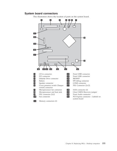
System board connectors<br />
This illustration shows the location of parts on the system board.<br />
▌1▐ CD in connector ▌12▐ Front USB2 connector<br />
▌2▐ PCI connector ▌13▐ Front USB1 connector<br />
▌3▐ Diskette Drive connector ▌14▐ BIOSWP<br />
▌4▐ Battery ▌15▐ SPI debug connector<br />
▌5▐ Speaker connector ▌16▐ COM2 connector<br />
▌6▐ Cover presence switch (Tamper<br />
switch) connector<br />
▌17▐ PSU Connector (2x12)<br />
▌7▐ Microprocessor fan connector ▌18▐ SATA connector (2)<br />
▌8▐ Microprocessor and heat sink ▌19▐ Clear CMOS/Recovery jumper<br />
▌9▐ PSU connector (2x2) ▌20▐ Front Audio connector<br />
▌10▐ Fan connector ▌21▐ PCI Express connector - Labeled on<br />
system board<br />
▌11▐ Memory connectors (2)<br />
<strong>Chapter</strong> 10. <strong>Replacing</strong> <strong>FRUs</strong> - Desktop computers 153


