Chapter 8. Replacing FRUs - CNET Content Solutions
Chapter 8. Replacing FRUs - CNET Content Solutions Chapter 8. Replacing FRUs - CNET Content Solutions
Replacing the system board 96 Hardware Maintenance Manual This procedure describes how to remove and replace a system board. The procedure varies depending upon the machine type. Important The heat sink and microprocessor might be very hot. Make sure these components are cool enough to safely handle before continuing this procedure. Note: When replacing the system board you must also order a new retention module for the new system board. Make sure you have a retention module for the new system board before continuing with this procedure. 1. Remove the cover. See “Removing the cover” on page 89. 2. Lift the fan duct off the heat sink fan. 3. Remove any adapter cards installed in the PCI connectors. 4. You might have to remove the drive bay assembly to access the system board. See “Accessing system board components and drives” on page 90. 5. Take note of the location of all cable connections on the system board and disconnect all cables. See the system board illustration for your machine type at “System board connectors” on page 88. 6. Remove the hard disk drive. See “Replacing the hard disk drive” on page 103. 7. Remove the screws that secure the system board to the chassis. 8. Lift the system board out of the chassis. 9. Remove the memory modules from the failing system board and install them in the same location on the new system board. 10. Disconnect the heat sink and fan assembly cable from the system board. See the system board illustration for your machine type at “System board connectors” on page 88. 11. Remove the four screws ▌1▐ securing the heat sink and fan assembly to the system board.
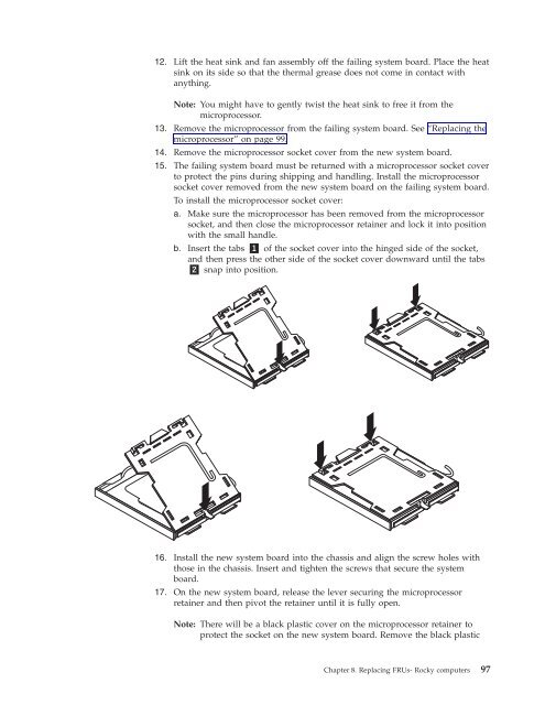
12. Lift the heat sink and fan assembly off the failing system board. Place the heat sink on its side so that the thermal grease does not come in contact with anything. Note: You might have to gently twist the heat sink to free it from the microprocessor. 13. Remove the microprocessor from the failing system board. See “Replacing the microprocessor” on page 99. 14. Remove the microprocessor socket cover from the new system board. 15. The failing system board must be returned with a microprocessor socket cover to protect the pins during shipping and handling. Install the microprocessor socket cover removed from the new system board on the failing system board. To install the microprocessor socket cover: a. Make sure the microprocessor has been removed from the microprocessor socket, and then close the microprocessor retainer and lock it into position with the small handle. b. Insert the tabs ▌1▐ of the socket cover into the hinged side of the socket, and then press the other side of the socket cover downward until the tabs ▌2▐ snap into position. 16. Install the new system board into the chassis and align the screw holes with those in the chassis. Insert and tighten the screws that secure the system board. 17. On the new system board, release the lever securing the microprocessor retainer and then pivot the retainer until it is fully open. Note: There will be a black plastic cover on the microprocessor retainer to protect the socket on the new system board. Remove the black plastic Chapter 8. Replacing FRUs- Rocky computers 97
- Page 51 and 52: Chapter 5. Diagnostics PC-Doctor fo
- Page 53 and 54: 7. When prompted, insert a blank, f
- Page 55 and 56: The Full Erase Hard Drive provides
- Page 57 and 58: Chapter 6. Using the Setup Utility
- Page 59 and 60: 3. Select the desired startup devic
- Page 61 and 62: Chapter 7. Symptom-to-FRU Index Har
- Page 63 and 64: Diagnostic Error Code FRU/Action 00
- Page 65 and 66: Diagnostic Error Code FRU/Action 00
- Page 67 and 68: Diagnostic Error Code FRU/Action 00
- Page 69 and 70: Diagnostic Error Code FRU/Action 01
- Page 71 and 72: Diagnostic Error Code FRU/Action 01
- Page 73 and 74: Diagnostic Error Code FRU/Action 01
- Page 75 and 76: Diagnostic Error Code FRU/Action 02
- Page 77 and 78: Diagnostic Error Code FRU/Action 07
- Page 79 and 80: Diagnostic Error Code FRU/Action 08
- Page 81 and 82: Diagnostic Error Code FRU/Action 17
- Page 83 and 84: Diagnostic Error Code FRU/Action 30
- Page 85 and 86: POST error codes Each time you powe
- Page 87 and 88: Miscellaneous error messages Messag
- Page 89 and 90: c. Memory modules d. Extended video
- Page 91 and 92: Chapter 8. Replacing FRUs (Types 70
- Page 93 and 94: Computer components The following i
- Page 95 and 96: Removing the cover Important Read C
- Page 97 and 98: 4. Using the blue handle▌1▐, li
- Page 99 and 100: Replacing the CMOS battery If the C
- Page 101: 7. Lift the power supply out of the
- Page 105 and 106: Replacing the microprocessor This p
- Page 107 and 108: Notes: a. Note the orientation of t
- Page 109 and 110: Replacing the hard disk drive Impor
- Page 111 and 112: Replacing an optical drive This pro
- Page 113 and 114: Replacing the power switch/LED asse
- Page 115 and 116: Replacing the system fan assembly T
- Page 117 and 118: Completing the FRU replacement Afte
- Page 119 and 120: Chapter 9. Replacing FRUs (Types 70
- Page 121 and 122: Computer components The following i
- Page 123 and 124: Removing the cover Important Read C
- Page 125 and 126: Replacing the power supply This pro
- Page 127 and 128: 11. Remove the four screws ▌1▐
- Page 129 and 130: 17. Lower the microprocessor straig
- Page 131 and 132: 5. Lift the heat sink and fan assem
- Page 133 and 134: 11. Lower the microprocessor straig
- Page 135 and 136: Replacing a PCI adapter This proced
- Page 137 and 138: Replacing the primary hard disk dri
- Page 139 and 140: 9. Align the drive cage pivot pin w
- Page 141 and 142: 4. Press the blue release button to
- Page 143 and 144: 10. Install the hard drive cage int
- Page 145 and 146: Replacing the diskette drive This p
- Page 147 and 148: 4. Install the new rear fan assembl
- Page 149 and 150: 6. Pull on the tips of the rubber m
- Page 151 and 152: Replacing the power switch/LED asse
12. Lift the heat sink and fan assembly off the failing system board. Place the heat<br />
sink on its side so that the thermal grease does not come in contact with<br />
anything.<br />
Note: You might have to gently twist the heat sink to free it from the<br />
microprocessor.<br />
13. Remove the microprocessor from the failing system board. See “<strong>Replacing</strong> the<br />
microprocessor” on page 99.<br />
14. Remove the microprocessor socket cover from the new system board.<br />
15. The failing system board must be returned with a microprocessor socket cover<br />
to protect the pins during shipping and handling. Install the microprocessor<br />
socket cover removed from the new system board on the failing system board.<br />
To install the microprocessor socket cover:<br />
a. Make sure the microprocessor has been removed from the microprocessor<br />
socket, and then close the microprocessor retainer and lock it into position<br />
with the small handle.<br />
b. Insert the tabs ▌1▐ of the socket cover into the hinged side of the socket,<br />
and then press the other side of the socket cover downward until the tabs<br />
▌2▐ snap into position.<br />
16. Install the new system board into the chassis and align the screw holes with<br />
those in the chassis. Insert and tighten the screws that secure the system<br />
board.<br />
17. On the new system board, release the lever securing the microprocessor<br />
retainer and then pivot the retainer until it is fully open.<br />
Note: There will be a black plastic cover on the microprocessor retainer to<br />
protect the socket on the new system board. Remove the black plastic<br />
<strong>Chapter</strong> <strong>8.</strong> <strong>Replacing</strong> <strong>FRUs</strong>- Rocky computers 97


