Euradwaste '08 - EU Bookshop - Europa
Euradwaste '08 - EU Bookshop - Europa Euradwaste '08 - EU Bookshop - Europa
The main waste canister characteristics, and the numbers of canisters that need to be disposed of according to the phase-out scenario, are given in Table 1. Table 1. Characteristics of the waste canisters for disposal of heat-generating waste in Germany HLW Canister CSD-C BSK Canister Number of canisters 4,778 8,764 ca. 5,525 Number of boreholes needed 30 55 95 Length mm 1,338 � 1,345 4,980 Diameter mm 430 � 440 � 440 Total mass kg ca. 492 � 850 5,226 Mass HM tHM - - 1.6 Heat generation kW • at loading 0.02 21,220 • after 10 years 120*) 3,030 • after 30 years 67**) 1,930 *) after 9 years **) after 29 years The BSK 3 concept, therefore, may provide a common solution for the emplacement of all types of heat-generating radioactive waste in Germany, thus considerably reducing the necessary effort in terms of time and costs. 3.2 Approach to developing the BSK 3 emplacement technology A research programme was launched in order to develop and test the necessary technical components for the transport and handling of BSK 3 canisters. The main objective was to develop the components for demonstrating the functionality and reliability of a suitable emplacement technology. In addition, the results of the tests and investigations are to provide all information required for the licensing of this new back-end technology, thus meeting the legal requirements for a German HLW repository. In the context of the Integrated Project ESDRED [1], the BSK 3 canister transport and emplacement concept is specific to the German reference concept in salt but it may be applicable to other host rocks as well. The following objectives for the BSK 3 research and development project were set: • General objective: - to develop and test the emplacement technology for BSK 3 canisters on a 1:1 scale, • Detailed objectives: - to prove the technical feasibility of constructing the single components as well as of the entire emplacement system for BSK 3 canisters - to prove the operational safety by corresponding demonstration tests, - to derive safety measures for the operation in a repository, - to investigate the approvability of the emplacement system. In accordance with this set of objectives, an emplacement system was developed for the handling and disposal of BSK 3 canisters that comprises a transfer cask, which provides appropriate shielding during the transport and emplacement process, a transport unit consisting of a mining locomotive and a transport cart, an emplacement device for handling the transfer cask and lowering the BSK 3 canister into the emplacement borehole, and a borehole lock which provides radiation pro- 262
tection during the operational phase of the repository. Figure 3 shows the components of the entire transport and emplacement system in an underground emplacement drift. It was selected out of a variety of different options. Aboveground, in a hot cell of a conditioning plant, the BSK 3 canister is inserted into the transfer cask. After shipment to the repository, the transfer cask is transported by the transport cart through the shaft to the emplacement drift underground. The mining locomotive drives the transport cart with the transfer cask to the emplacement device. The emplacement device, previously positioned on top of the emplacement borehole, lifts the transfer cask from the transport cart, tilts the cask into an upright position and lowers it down onto the top of the borehole lock. The borehole lock and the lock of the transfer cask are opened simultaneously, and the BSK 3 canister is lowered down by means of a rope and canister grab. Figure 3: Sketch of the BSK 3 transport and emplacement system with all necessary components The BSK 3 emplacement system required the development of the following new components: • a BSK 3 canister, capable to contain the rods of 3 PWR or 9 BWR fuel assemblies, • a transfer cask for the safe enclosure and transport of the BSK 3 canister, • a suitable emplacement device, • a borehole lock, and • a transport unit consisting of a transport cart and a battery-operated mining locomotive for rail-bound transport in the repository. An early idea to reuse the transport cart, which had been successfully used during the demonstration tests with POLLUX ® casks in the 1990s, had to be discarded. From an economical point of view it was less expensive to build a new one than to modify the existing one. However, the batteryoperated mining locomotive is used again. 3.3 Demonstration programme with BSK 3 canister Due to the lack of an underground laboratory in salt rock in Germany it was decided to perform the demonstration tests in a surface facility. For this purpose, a former turbine hall of a power station owned by E.ON in the village of Landesbergen in the vicinity of Hanover, Lower-Saxony, has been rented. This building provides the possibility to simulate the emplacement process of a BSK 3 canister in a vertical borehole. The components of the emplacement system are assembled at a level of 10 m above ground floor (Fig. 4), while a 10-m-long vertical steel metal casing simulates the em- 263
- Page 228 and 229: [7] Wenk H.-R., Voltolini, M., Mazu
- Page 230 and 231: that provided by various national s
- Page 232 and 233: system robustness, rather than as s
- Page 234 and 235: Regarding diffusion studies perform
- Page 236 and 237: 7. EDZ characterization and evoluti
- Page 238 and 239: [4] Alonso, J. et al. 2004: Bentoni
- Page 240 and 241: There has been a significant change
- Page 242 and 243: 226
- Page 244 and 245: 228
- Page 246 and 247: 2. Methodology ESDRED has been focu
- Page 248 and 249: Figure 3: Reduced scale mock-up aft
- Page 250 and 251: Figure 8: Demonstration of emplacem
- Page 252 and 253: The various reports produced by the
- Page 254 and 255: 238
- Page 256 and 257: 2. Methodology In general, the work
- Page 258 and 259: limitations of the selected press.
- Page 260 and 261: Figure 3.2.1 Schematic representati
- Page 262 and 263: which was relatively homogeneous in
- Page 264 and 265: Figure 3.3.1 Emplacement of SF-Cani
- Page 266 and 267: 1.650 1.600 1.550 1.500 1.450 1.400
- Page 268 and 269: the outlet with some pressure and f
- Page 270 and 271: A experiment, using cross-hole seis
- Page 272 and 273: This seal will be implemented as ri
- Page 274 and 275: [6] Miehe, R., Kröhn, P., Moog, H.
- Page 276 and 277: dence. For waste canister transport
- Page 280 and 281: placement borehole. The BSK 3 canis
- Page 282 and 283: Figure 6: Sketch of the Pushing Rob
- Page 284 and 285: 268
- Page 286 and 287: 1.1 Water Cushion Application SKB (
- Page 288 and 289: In the case of SKB and Posiva, the
- Page 290 and 291: Deposition machine tests with load
- Page 292 and 293: Figure 10: Details of electrical pu
- Page 294 and 295: the very heavy weight (43 ton) of t
- Page 296 and 297: is no experience in either the work
- Page 298 and 299: the case of the long plug elaborate
- Page 300 and 301: values measured in the percolated w
- Page 302 and 303: plug the concrete was mixed manuall
- Page 304 and 305: 2.3 Testing of low-pH shotcrete for
- Page 306 and 307: 290
- Page 308 and 309: energy is produced by fission of ur
- Page 310 and 311: 3.2. Integration 3.2.1. Pool Facili
- Page 312 and 313: 3.4. Education and Training Apart f
- Page 314 and 315: 298
- Page 316 and 317: Fig. 1.1: EU Member States involved
- Page 318 and 319: Fig. 1.3: Stakeholders and interest
- Page 320 and 321: - Present state of scientific level
- Page 322 and 323: 6. Training courses Key events of t
- Page 324 and 325: 308
- Page 326 and 327: materials, the essential aspects of
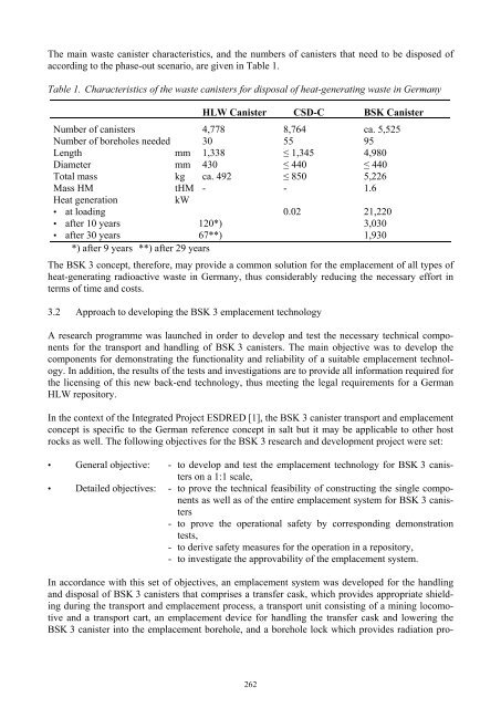
The main waste canister characteristics, and the numbers of canisters that need to be disposed of<br />
according to the phase-out scenario, are given in Table 1.<br />
Table 1. Characteristics of the waste canisters for disposal of heat-generating waste in Germany<br />
HLW Canister CSD-C BSK Canister<br />
Number of canisters 4,778 8,764 ca. 5,525<br />
Number of boreholes needed 30 55 95<br />
Length mm 1,338 � 1,345 4,980<br />
Diameter mm 430 � 440 � 440<br />
Total mass kg ca. 492 � 850 5,226<br />
Mass HM tHM - - 1.6<br />
Heat generation kW<br />
• at loading 0.02 21,220<br />
• after 10 years 120*) 3,030<br />
• after 30 years 67**) 1,930<br />
*) after 9 years **) after 29 years<br />
The BSK 3 concept, therefore, may provide a common solution for the emplacement of all types of<br />
heat-generating radioactive waste in Germany, thus considerably reducing the necessary effort in<br />
terms of time and costs.<br />
3.2 Approach to developing the BSK 3 emplacement technology<br />
A research programme was launched in order to develop and test the necessary technical components<br />
for the transport and handling of BSK 3 canisters. The main objective was to develop the<br />
components for demonstrating the functionality and reliability of a suitable emplacement technology.<br />
In addition, the results of the tests and investigations are to provide all information required for<br />
the licensing of this new back-end technology, thus meeting the legal requirements for a German<br />
HLW repository.<br />
In the context of the Integrated Project ESDRED [1], the BSK 3 canister transport and emplacement<br />
concept is specific to the German reference concept in salt but it may be applicable to other host<br />
rocks as well. The following objectives for the BSK 3 research and development project were set:<br />
• General objective: - to develop and test the emplacement technology for BSK 3 canisters<br />
on a 1:1 scale,<br />
• Detailed objectives: - to prove the technical feasibility of constructing the single components<br />
as well as of the entire emplacement system for BSK 3 canisters<br />
- to prove the operational safety by corresponding demonstration<br />
tests,<br />
- to derive safety measures for the operation in a repository,<br />
- to investigate the approvability of the emplacement system.<br />
In accordance with this set of objectives, an emplacement system was developed for the handling<br />
and disposal of BSK 3 canisters that comprises a transfer cask, which provides appropriate shielding<br />
during the transport and emplacement process, a transport unit consisting of a mining locomotive<br />
and a transport cart, an emplacement device for handling the transfer cask and lowering the<br />
BSK 3 canister into the emplacement borehole, and a borehole lock which provides radiation pro-<br />
262


