Euradwaste '08 - EU Bookshop - Europa
Euradwaste '08 - EU Bookshop - Europa Euradwaste '08 - EU Bookshop - Europa
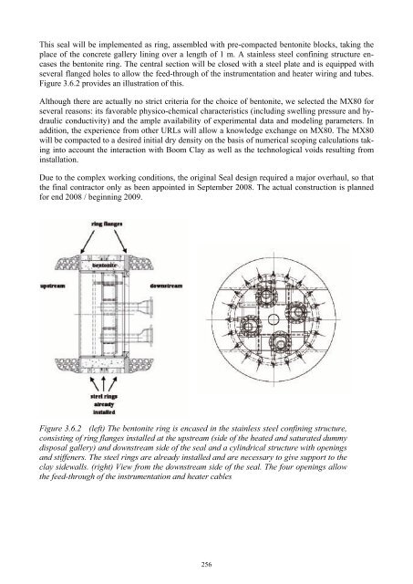
This seal will be implemented as ring, assembled with pre-compacted bentonite blocks, taking the place of the concrete gallery lining over a length of 1 m. A stainless steel confining structure encases the bentonite ring. The central section will be closed with a steel plate and is equipped with several flanged holes to allow the feed-through of the instrumentation and heater wiring and tubes. Figure 3.6.2 provides an illustration of this. Although there are actually no strict criteria for the choice of bentonite, we selected the MX80 for several reasons: its favorable physico-chemical characteristics (including swelling pressure and hydraulic conductivity) and the ample availability of experimental data and modeling parameters. In addition, the experience from other URLs will allow a knowledge exchange on MX80. The MX80 will be compacted to a desired initial dry density on the basis of numerical scoping calculations taking into account the interaction with Boom Clay as well as the technological voids resulting from installation. Due to the complex working conditions, the original Seal design required a major overhaul, so that the final contractor only as been appointed in September 2008. The actual construction is planned for end 2008 / beginning 2009. Figure 3.6.2 (left) The bentonite ring is encased in the stainless steel confining structure, consisting of ring flanges installed at the upstream (side of the heated and saturated dummy disposal gallery) and downstream side of the seal and a cylindrical structure with openings and stiffeners. The steel rings are already installed and are necessary to give support to the clay sidewalls. (right) View from the downstream side of the seal. The four openings allow the feed-through of the instrumentation and heater cables 256
4. Conclusions Half-way through the final project year, Module 1 has achieved most of its objectives: • ANDRA has succeeded in the cold compaction of a MX-80 bentonite / quartz sand mixture prepared as a powder, to obtain the prefabricated buffer rings described in their Dossier 2005 report to the French Government. ANDRA has also successfully tested the handling of these buffer rings and their rigidity. • ONDRAF/NIRAS has demonstrated the feasibility of backfilling the annular void around a horizontally disposed high level waste package, using two different emplacement techniques: (1) projection of a dry granular material, for which sand, cement, bentonite and mixtures thereof were used, (2) injection of a custom-made high pH grout designed to have the required thermal, chemical and physical characteristics. Both emplacement techniques have been tested on reduced-scale mock-ups. The grout injection technique was also tested on a 30-m long full-scale mock-up. The result still needs to be evaluated. • NAGRA, using auger technology and a reduced-scale steel model of a horizontal drift with a waste container disposed on a bed of prefabricated bentonite blocks, has tested the emplacement of a range of bimodal mixtures of granular bentonite. NAGRA succeeded in achieving the desired dry density of the emplaced buffer material. • GRS is satisfactorily running performance tests on four seals of different bentonite-sand composition in boreholes at the Mont Terri URL. These in-situ tests, and also the preceding laboratory mock-up testing, indicate that the envisaged sealing function will be confirmed by the actual tests, but at much lower seal saturation rates than predicted by computer models. The foreseen nitrogen gas injection tests, after full seal saturation, will therefore most probably be done after the project end date. • NDA is executing a test program to advance non-intrusive monitoring based on cross-hole micro-seismic tomography. In cooperation with the Swiss Federal Institute of Technology (ETH Zurich), a full wave inversion code and an anisotropic model of the clay test environment have been developed to interpret the seismic echoes. The installation of a seal in the Mol URL is the only demonstration test that remains to be done. 5. Acknowledgements This project has been co-funded by the European Commission and performed as part of the sixth Euratom Framework Programme for nuclear research and training activities (2002-2006) under contract FI6W-CT-2004-508851. References [1] ANDRA Dossier 2005 “Architecture and Management of a Geological Disposal System”, [2] “SAFIR 2: Belgian R&D Programme on the Deep Disposal of High-Level and Long-Lived Radioactive Waste – An International Peer Review”, NEA-OECD report, issued 2003; [3] Nagra, 2002. Projekt Opalinuston – Konzept für die Anlage und den Betrieb eines geologischen Tiefenlagers. Nagra Technical Report NTB 02-02. Wettingen, Switzerland. [4] Nagra, 2007. Plötze, M., Weber, H.P., 2007. ESDRED: Emplacement tests with granular Bentonit MX-80. Nagra Working Report NAB 07-24. Wettingen, Switzerland. [5] Fries, T., Claudel, A., Weber, H., Johnson, L., Leupin, O. 2008. The Swiss concept for the disposal of spent fuel and vitrified HLW. Proceedings of the ESDRED Prague Conference, June 2008. 257
- Page 222 and 223: layout of cells developed by ENPC w
- Page 224 and 225: ) a) e) d) f) d) e) f) c) Figure 3.
- Page 226 and 227: EDZ removal by additional excavatio
- Page 228 and 229: [7] Wenk H.-R., Voltolini, M., Mazu
- Page 230 and 231: that provided by various national s
- Page 232 and 233: system robustness, rather than as s
- Page 234 and 235: Regarding diffusion studies perform
- Page 236 and 237: 7. EDZ characterization and evoluti
- Page 238 and 239: [4] Alonso, J. et al. 2004: Bentoni
- Page 240 and 241: There has been a significant change
- Page 242 and 243: 226
- Page 244 and 245: 228
- Page 246 and 247: 2. Methodology ESDRED has been focu
- Page 248 and 249: Figure 3: Reduced scale mock-up aft
- Page 250 and 251: Figure 8: Demonstration of emplacem
- Page 252 and 253: The various reports produced by the
- Page 254 and 255: 238
- Page 256 and 257: 2. Methodology In general, the work
- Page 258 and 259: limitations of the selected press.
- Page 260 and 261: Figure 3.2.1 Schematic representati
- Page 262 and 263: which was relatively homogeneous in
- Page 264 and 265: Figure 3.3.1 Emplacement of SF-Cani
- Page 266 and 267: 1.650 1.600 1.550 1.500 1.450 1.400
- Page 268 and 269: the outlet with some pressure and f
- Page 270 and 271: A experiment, using cross-hole seis
- Page 274 and 275: [6] Miehe, R., Kröhn, P., Moog, H.
- Page 276 and 277: dence. For waste canister transport
- Page 278 and 279: The main waste canister characteris
- Page 280 and 281: placement borehole. The BSK 3 canis
- Page 282 and 283: Figure 6: Sketch of the Pushing Rob
- Page 284 and 285: 268
- Page 286 and 287: 1.1 Water Cushion Application SKB (
- Page 288 and 289: In the case of SKB and Posiva, the
- Page 290 and 291: Deposition machine tests with load
- Page 292 and 293: Figure 10: Details of electrical pu
- Page 294 and 295: the very heavy weight (43 ton) of t
- Page 296 and 297: is no experience in either the work
- Page 298 and 299: the case of the long plug elaborate
- Page 300 and 301: values measured in the percolated w
- Page 302 and 303: plug the concrete was mixed manuall
- Page 304 and 305: 2.3 Testing of low-pH shotcrete for
- Page 306 and 307: 290
- Page 308 and 309: energy is produced by fission of ur
- Page 310 and 311: 3.2. Integration 3.2.1. Pool Facili
- Page 312 and 313: 3.4. Education and Training Apart f
- Page 314 and 315: 298
- Page 316 and 317: Fig. 1.1: EU Member States involved
- Page 318 and 319: Fig. 1.3: Stakeholders and interest
- Page 320 and 321: - Present state of scientific level
This seal will be implemented as ring, assembled with pre-compacted bentonite blocks, taking the<br />
place of the concrete gallery lining over a length of 1 m. A stainless steel confining structure encases<br />
the bentonite ring. The central section will be closed with a steel plate and is equipped with<br />
several flanged holes to allow the feed-through of the instrumentation and heater wiring and tubes.<br />
Figure 3.6.2 provides an illustration of this.<br />
Although there are actually no strict criteria for the choice of bentonite, we selected the MX80 for<br />
several reasons: its favorable physico-chemical characteristics (including swelling pressure and hydraulic<br />
conductivity) and the ample availability of experimental data and modeling parameters. In<br />
addition, the experience from other URLs will allow a knowledge exchange on MX80. The MX80<br />
will be compacted to a desired initial dry density on the basis of numerical scoping calculations taking<br />
into account the interaction with Boom Clay as well as the technological voids resulting from<br />
installation.<br />
Due to the complex working conditions, the original Seal design required a major overhaul, so that<br />
the final contractor only as been appointed in September 2008. The actual construction is planned<br />
for end 2008 / beginning 2009.<br />
Figure 3.6.2 (left) The bentonite ring is encased in the stainless steel confining structure,<br />
consisting of ring flanges installed at the upstream (side of the heated and saturated dummy<br />
disposal gallery) and downstream side of the seal and a cylindrical structure with openings<br />
and stiffeners. The steel rings are already installed and are necessary to give support to the<br />
clay sidewalls. (right) View from the downstream side of the seal. The four openings allow<br />
the feed-through of the instrumentation and heater cables<br />
256


