- Page 2 and 3:
Interested in European research? Re
- Page 4 and 5:
LEGAL NOTICE Neither the European C
- Page 7 and 8:
TABLE OF CONTENTS FOREWORD iii CONF
- Page 9 and 10:
“Impact of advanced fuel cycle sc
- Page 11 and 12:
“Sensitivity analysis techniques
- Page 13 and 14:
Topic: Support actions SAPIERR-II -
- Page 15:
CONFERENCE SUMMARIES
- Page 18 and 19:
supported. The Commission believes
- Page 20 and 21:
Ms Monika Hammarström of SKB in Sw
- Page 22 and 23:
Dr Bruno of Amphos 21 urged the swi
- Page 24 and 25:
measurements of actinides to determ
- Page 26 and 27:
Dr Peter Blümling of Nagra in Swit
- Page 28 and 29:
Future directions There seemed to b
- Page 31 and 32:
1. Introduction Keynote Address Pet
- Page 33 and 34:
tive waste management, a considerab
- Page 35 and 36:
the decision making process. The se
- Page 37:
All initiatives leading to encourag
- Page 40 and 41:
tegrating them as part of advanced
- Page 43:
General introduction and objectives
- Page 47 and 48:
Radioactive waste management: Where
- Page 49 and 50:
The intense development in nuclear
- Page 51 and 52:
Figure 3: Schematic diagram of the
- Page 53 and 54:
contributed to enhance knowledge ab
- Page 55 and 56:
the first time in French history, a
- Page 57 and 58:
PANEL DISCUSSION Summary of the Pan
- Page 59:
With the support of IAEA preliminar
- Page 63 and 64:
Assessment of Financial Provisions
- Page 65 and 66:
collected in the cost of the nuclea
- Page 67 and 68:
erated by Fortum) and one PWR unit
- Page 69 and 70:
pected. As to tunnel backfilling, t
- Page 71 and 72:
ferent, the technological solutions
- Page 73 and 74:
PANEL DISCUSSION Summary of the Pan
- Page 75:
Discussion: As a response to a ques
- Page 79 and 80:
Cooperation in the development of g
- Page 81 and 82:
During the 1980’s it was realized
- Page 83:
government on the operating license
- Page 86 and 87:
tions. EDRAM is another example of
- Page 88 and 89:
Discussion: The chairman opened the
- Page 91 and 92:
Communicating the safety of radioac
- Page 93 and 94:
Communicating the Safety of Radioac
- Page 95 and 96:
Geological repositories … Differe
- Page 97 and 98:
Geological long-term stability (pla
- Page 99 and 100:
Times & doses in perspective (examp
- Page 101 and 102:
Trust is generated (by the regulato
- Page 103 and 104:
PANEL DISCUSSION Summary of the Pan
- Page 105:
4. The regulators could play a very
- Page 108 and 109:
Europe's nuclear industries, theref
- Page 110 and 111:
filled - one key example being coll
- Page 112 and 113:
Table 2. FP6 Integrated Projects an
- Page 114 and 115:
EUROTRANS focuses on the transmutat
- Page 116 and 117:
consensus that geological disposal
- Page 118 and 119:
102
- Page 120 and 121:
104
- Page 122 and 123:
significantly reduce the quantities
- Page 124 and 125:
Pyrochemical processes rely on refi
- Page 126 and 127:
Figure 3: Schematic layout of an el
- Page 128 and 129:
Considering pyrochemistry technolog
- Page 130 and 131:
agreed for support through an integ
- Page 132 and 133:
Table 1: Fuels irradiated in the SU
- Page 134 and 135:
lead cooling (see Fig. 5). Alternat
- Page 136 and 137:
Figure 6: Principle design characte
- Page 138 and 139:
Table 6: FUTURIX FTA fuels Fuel nam
- Page 140 and 141:
124
- Page 142 and 143:
After a review of the present statu
- Page 144 and 145:
suranium elements, “repository av
- Page 146 and 147:
nificant fraction of fast reactors.
- Page 148 and 149:
high level waste at the considered
- Page 150 and 151:
Pu or M.A. by the time it is needed
- Page 152 and 153:
of U and Pu only. P&T could complem
- Page 154 and 155:
suranium elements, the thermal load
- Page 156 and 157:
Phase-Out TRU Transmutation Scenari
- Page 158 and 159:
10 nuclear nations (Argentina, Braz
- Page 160 and 161:
elease, strong radiation, pressure
- Page 162 and 163:
A1 3.79E+08 270 7.12E-07 A2 3.51E+0
- Page 164 and 165:
nuclear fission in the reactors. Th
- Page 166 and 167:
5. Conclusions The HLW arising from
- Page 168 and 169:
152
- Page 170 and 171:
tinides (MA) are destined for geolo
- Page 172 and 173:
[3] Enrique González: Head of Nucl
- Page 174 and 175:
158
- Page 176 and 177:
160
- Page 178 and 179:
erage level of funding of research
- Page 180 and 181:
Prior to NF-PRO, the question wheth
- Page 182 and 183:
nant exchangeable cation. This chan
- Page 184 and 185:
eal concentration gradient in sampl
- Page 186 and 187:
access shafts, providing higher per
- Page 188 and 189:
172
- Page 190 and 191:
in the European coordinated action
- Page 192 and 193:
proved, with amongst others the det
- Page 194 and 195:
4. Discussion Tests with dissolved
- Page 196 and 197:
though with a slow rate. The data i
- Page 198 and 199:
surface. The coupling between water
- Page 200 and 201:
nuclear waste within the near-field
- Page 202 and 203:
tion of the column [2]. Moreover, t
- Page 204 and 205:
case, the iron diffusion front in t
- Page 206 and 207:
5.1 Sorption As an example of the t
- Page 208 and 209:
corrosion; up-scaling of clay alter
- Page 210 and 211:
Bentonite barriers are very importa
- Page 212 and 213:
To determine the impact of temperat
- Page 214 and 215:
in the underground laboratory in Gr
- Page 216 and 217:
under isothermal conditions. If the
- Page 218 and 219:
202
- Page 220 and 221: Zones around such openings which ex
- Page 222 and 223: layout of cells developed by ENPC w
- Page 224 and 225: ) a) e) d) f) d) e) f) c) Figure 3.
- Page 226 and 227: EDZ removal by additional excavatio
- Page 228 and 229: [7] Wenk H.-R., Voltolini, M., Mazu
- Page 230 and 231: that provided by various national s
- Page 232 and 233: system robustness, rather than as s
- Page 234 and 235: Regarding diffusion studies perform
- Page 236 and 237: 7. EDZ characterization and evoluti
- Page 238 and 239: [4] Alonso, J. et al. 2004: Bentoni
- Page 240 and 241: There has been a significant change
- Page 242 and 243: 226
- Page 244 and 245: 228
- Page 246 and 247: 2. Methodology ESDRED has been focu
- Page 248 and 249: Figure 3: Reduced scale mock-up aft
- Page 250 and 251: Figure 8: Demonstration of emplacem
- Page 252 and 253: The various reports produced by the
- Page 254 and 255: 238
- Page 256 and 257: 2. Methodology In general, the work
- Page 258 and 259: limitations of the selected press.
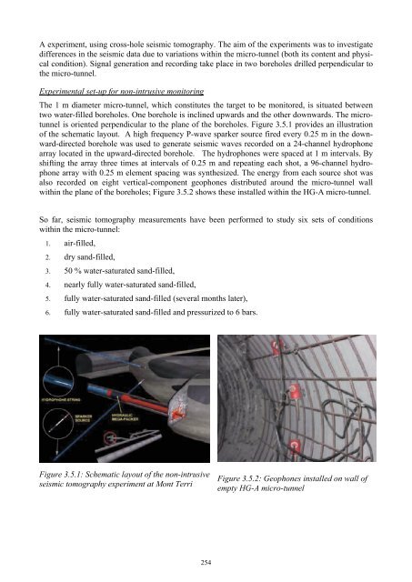
- Page 260 and 261: Figure 3.2.1 Schematic representati
- Page 262 and 263: which was relatively homogeneous in
- Page 264 and 265: Figure 3.3.1 Emplacement of SF-Cani
- Page 266 and 267: 1.650 1.600 1.550 1.500 1.450 1.400
- Page 268 and 269: the outlet with some pressure and f
- Page 272 and 273: This seal will be implemented as ri
- Page 274 and 275: [6] Miehe, R., Kröhn, P., Moog, H.
- Page 276 and 277: dence. For waste canister transport
- Page 278 and 279: The main waste canister characteris
- Page 280 and 281: placement borehole. The BSK 3 canis
- Page 282 and 283: Figure 6: Sketch of the Pushing Rob
- Page 284 and 285: 268
- Page 286 and 287: 1.1 Water Cushion Application SKB (
- Page 288 and 289: In the case of SKB and Posiva, the
- Page 290 and 291: Deposition machine tests with load
- Page 292 and 293: Figure 10: Details of electrical pu
- Page 294 and 295: the very heavy weight (43 ton) of t
- Page 296 and 297: is no experience in either the work
- Page 298 and 299: the case of the long plug elaborate
- Page 300 and 301: values measured in the percolated w
- Page 302 and 303: plug the concrete was mixed manuall
- Page 304 and 305: 2.3 Testing of low-pH shotcrete for
- Page 306 and 307: 290
- Page 308 and 309: energy is produced by fission of ur
- Page 310 and 311: 3.2. Integration 3.2.1. Pool Facili
- Page 312 and 313: 3.4. Education and Training Apart f
- Page 314 and 315: 298
- Page 316 and 317: Fig. 1.1: EU Member States involved
- Page 318 and 319: Fig. 1.3: Stakeholders and interest
- Page 320 and 321:
- Present state of scientific level
- Page 322 and 323:
6. Training courses Key events of t
- Page 324 and 325:
308
- Page 326 and 327:
materials, the essential aspects of
- Page 328 and 329:
2.1 Geological formation scale (10
- Page 330 and 331:
porosity outside the clay interlaye
- Page 332 and 333:
eduction in De with increasing prop
- Page 334 and 335:
well-defined profile, with the high
- Page 336 and 337:
Th(IV) sorption on montmorillonite
- Page 338 and 339:
RN migration experiments and model
- Page 340 and 341:
tion/organization and its Cu(II) re
- Page 342 and 343:
326
- Page 344 and 345:
ganic/organic colloids”; WP 4.5
- Page 346 and 347:
Figure 1: Schematic of the FEBEX dr
- Page 348 and 349:
within feldspars in the three grani
- Page 350 and 351:
Colloid Concentration (ppm) 160 140
- Page 352 and 353:
form. Clay colloids were detected i
- Page 354 and 355:
References [1] Retrock (2005). Trea
- Page 356 and 357:
vance on radionuclide migration. Ma
- Page 358 and 359:
342
- Page 360 and 361:
The Ruprechtov site, located in the
- Page 362 and 363:
Colloid Concentration / μg/l 10000
- Page 364 and 365:
exists as a stable mineral phase in
- Page 366 and 367:
pared to other sites with SOC-beari
- Page 368 and 369:
[3] Hauser, W. Geckeis, H., Götz,
- Page 370 and 371:
The science and technology group, r
- Page 372 and 373:
FEPCAT RTDC 1 RTDC 2 RTDC 3 Clay-ri
- Page 374 and 375:
A1: Transport mechanisms Diffusivit
- Page 376 and 377:
360
- Page 378 and 379:
maintaining and develop competence
- Page 380 and 381:
A project would be justified to det
- Page 382 and 383:
366
- Page 384 and 385:
368
- Page 386 and 387:
The main goal of RTDC-1 is to provi
- Page 388 and 389:
3. RTDC3 In RTD component 3 methodo
- Page 390 and 391:
lower depths are less saline. For t
- Page 392 and 393:
[3] Marivoet, J., Beuth, T., Alonso
- Page 394 and 395:
certainty, conducted in RTDC-1 as W
- Page 396 and 397:
A simplistic summary might place PA
- Page 398 and 399:
There are at least three non-numeri
- Page 400 and 401:
10-11 June 2008. The workshop was a
- Page 402 and 403:
Close dialogue between a regulator
- Page 404 and 405:
ony, interactions, etc., and to che
- Page 406 and 407:
specific sampling strategy, with th
- Page 408 and 409:
2.2.3 Graphical methods Let us call
- Page 410 and 411:
3. The sensitivity analysis benchma
- Page 412 and 413:
4. Discussion and conclusions Three
- Page 414 and 415:
398
- Page 416 and 417:
2. Methodology The project particip
- Page 418 and 419:
Closely related to this proposal on
- Page 420 and 421:
4.3 Structure The TP structure must
- Page 422 and 423:
4.5 Implementation It is proposed t
- Page 424 and 425:
5.1 The CARD Project has shown that
- Page 426 and 427:
� What steps should be taken to m
- Page 428 and 429:
412
- Page 430 and 431:
414
- Page 432 and 433:
materials. For attaining the stated
- Page 434 and 435:
the bottom of the heated press-mold
- Page 436 and 437:
420
- Page 438 and 439:
422
- Page 440 and 441:
focuses on the study of the combine
- Page 442 and 443:
emitting radioactive waste to study
- Page 444 and 445:
428
- Page 446 and 447:
2.1 Laboratory experiment The dispo
- Page 448 and 449:
3. Results 3.1 Laboratory experimen
- Page 450 and 451:
Barrier. Clays in Natural & Enginee
- Page 452 and 453:
2. Experimental data 2.1 Laboratory
- Page 454 and 455:
sented in the accompanying poster,
- Page 456 and 457:
440
- Page 458 and 459:
situ stress to model the gallery ex
- Page 460 and 461:
tive crack network, oriented along
- Page 462 and 463:
446
- Page 464 and 465:
ous reasons, SCK•CEN chose to foc
- Page 466 and 467:
lery, are already monitoring temper
- Page 468 and 469:
[1] Bernier F., Li X.L., Weetjens E
- Page 470 and 471:
Concrete The cement used is an Ordi
- Page 472 and 473:
Brucite Ettringite 10 �m 8 �m F
- Page 474 and 475:
458
- Page 476 and 477:
2. Methodology In the case of cylin
- Page 478 and 479:
cell dismantled after 6 months, roo
- Page 480 and 481:
[3] G.E. Gdowski, Humid Air Corrosi
- Page 482 and 483:
crucial to predict the hydration ra
- Page 484 and 485:
load is higher, since the load appl
- Page 486 and 487:
[4] Gens, A. & Alonso, E. 1992. A f
- Page 488 and 489:
2. Experimental Methodology A salt
- Page 490 and 491:
proof of healing in salt rocks. It
- Page 492 and 493:
476
- Page 494 and 495:
obtained experimental results [1].
- Page 496 and 497:
dependent shear strength softening
- Page 498 and 499:
482
- Page 500 and 501:
elease falls typically between 1 an
- Page 502 and 503:
Figure 3: Left: Spent fuel surface
- Page 504 and 505:
488
- Page 506 and 507:
1. Data compilation and evaluation
- Page 508 and 509:
Volumetric deformation [%] 20 18 16
- Page 510 and 511:
An overview of the test procedure w
- Page 512 and 513:
496
- Page 514 and 515:
The works performed within RTDC-1 p
- Page 516 and 517:
Integrated Project “Fundamental P
- Page 518 and 519:
502
- Page 520 and 521:
The Ruprechtov natural analogue sit
- Page 522 and 523:
esults and integrated to develop a
- Page 524 and 525:
508
- Page 526 and 527:
510
- Page 528 and 529:
from 12.5 to 13.5, have high ionic
- Page 530 and 531:
elative intensity (cps) 8000 6000 4
- Page 532 and 533:
516
- Page 534 and 535:
518
- Page 536 and 537:
2. SAPIERR I and II In Europe, the
- Page 538 and 539:
after extensive interactions have t
- Page 540 and 541:
eing partners if an ERDO is formall
- Page 542 and 543:
526
- Page 544 and 545:
2. Methodology Based on existing da
- Page 546 and 547:
external funds ensuring the indepen
- Page 548 and 549:
532
- Page 550 and 551:
534
- Page 552 and 553:
Mr Jozef BALAZ JAVYS, a.s. - Nuclea
- Page 554 and 555:
Prof. Gunnar Johan BUCKAU Forschung
- Page 556 and 557:
Dr Mario DIONISI APAT - Dipartiment
- Page 558 and 559:
Dr Paloma GÓMEZ GONZÁLEZ CIEMAT -
- Page 560 and 561:
Ms Aurélie JESTIN SOGEDEC Z.I. Dig
- Page 562 and 563:
Dr Patrick MAJERUS Ministry of Heal
- Page 564 and 565:
Mr Zoltán NAGY PURAM - Department
- Page 566 and 567:
Ms Katerina PTACKOVA European Commi
- Page 568 and 569:
Prof. Christian SCHRÖDER Universit
- Page 570 and 571:
Dr Ján TIMUL'ÁK DECOM Slovakia, s
- Page 572:
Dr. Eng. Shuichi YAMAMOTO Obayashi
- Page 575:
Publications for sale: • via EU B


