Euradwaste '08 - EU Bookshop - Europa
Euradwaste '08 - EU Bookshop - Europa
Euradwaste '08 - EU Bookshop - Europa

Create successful ePaper yourself
Turn your PDF publications into a flip-book with our unique Google optimized e-Paper software.
Interested in European research?<br />
Research* eu is our monthly magazine keeping you in touch with main developments (results, programmes,<br />
events, etc.).<br />
It is available in English, French, German and Spanish. A free sample copy or free subscription can be obtained<br />
from:<br />
European Commission<br />
Directorate-General for Research<br />
Communication Unit<br />
B-1049 Brussels<br />
Fax (32-2) 29-58220<br />
E-mail: research-eu@ec.europa.eu<br />
Internet: http://ec.europa.eu/research/research-eu<br />
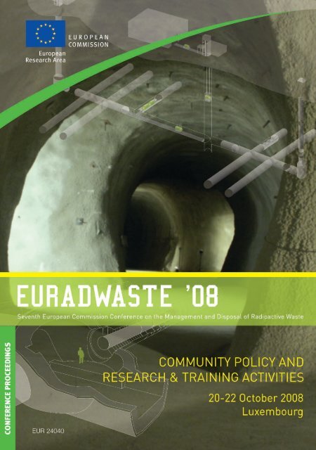
Cover:<br />
Background: Mont Terri Underground Rock Laboratory<br />
© Cornet Photoshopping GmbH, Zürich<br />
Graphic:<br />
courtesy of ANDRA, France<br />
Courtesy of ONDRAF/NIRAS, Belgium<br />
<strong>EU</strong>ROPEAN COMMISSION<br />
Directorate-General for Research<br />
Directorate J — Energy (Euratom)<br />
Unit J.2— Fission<br />
European Commission<br />
Office CDMA 01/61<br />
B-1049 Brussels<br />
Tel. (32-2) 29-61 670<br />
Fax (32-2) 29-54 991<br />
E-mail: Christophe.Davies@ec.europa.eu
<strong>EU</strong>ROPEAN COMMISSION<br />
<strong>Euradwaste</strong> <strong>'08</strong><br />
Seventh European Commission Conference on the Management<br />
and Disposal of Radioactive Waste<br />
Community Policy and<br />
Research & Training Activities<br />
Edited by C. Davies<br />
Directorate-General for Research<br />
2009 Euratom <strong>EU</strong>R 24040
LEGAL NOTICE<br />
Neither the European Commission nor any person acting on behalf of the Commission is responsible for the use<br />
which might be made of the following information.<br />
The views expressed in this publication are the sole responsibility of the author and do not necessarily reflect the<br />
views of the European Commission.<br />
A great deal of additional information on the European Union is available on the Internet.<br />
It can be accessed through the <strong>Europa</strong> server (http://europa.eu).<br />
Cataloguing data can be found at the end of this publication.<br />
Luxembourg: Publications Office of the European Union, 2009<br />
ISBN 978-92-79-13105-9<br />
doi: 10.2777/46864<br />
© European Communities, 2009<br />
Reproduction is authorised provided the source is acknowledged.<br />
Printed in France<br />
PRINTED ON WHITE CHLORINE-FREE PAPER<br />
<strong>EU</strong>ROPE DIRECT is a service to help you find answers<br />
to your questions about the European Union<br />
Freephone number (*):<br />
00 800 6 7 8 9 10 11<br />
(*) Certain mobile telephone operators do not allow access to 00 800 numbers<br />
or these calls may be billed
FOREWORD<br />
The Euratom Treaty celebrated its 50 th anniversary in 2007. Promotion of research and spreading of scientific<br />
and technical knowledge for the peaceful use of nuclear energy have been and remain a core task of the<br />
Treaty. Since the mid-70s, the European Commission (EC) has supported R&D on the management of radioactive<br />
waste as part of Euratom multi-annual programmes, the results being reported at successive<br />
<strong>Euradwaste</strong> conferences. This was the 7 th conference in the series and not only was a showcase event for<br />
R&D performed in the 6 th Euratom Framework Programme (FP6, 2002-2006) but also presented more general<br />
socio-political issues and related <strong>EU</strong> strategy in the field.<br />
Energy is now at the top of the political agenda, with nuclear power an important element in the debate. A<br />
number of initiatives have recently been launched that contribute to the Community's evolving strategy in<br />
this field. The European Nuclear Energy Forum (ENEF) is facilitating a broad stakeholder dialogue and<br />
analysis of key issues. On the regulatory side, a High Level Group on Nuclear Safety and Waste Management<br />
(since renamed ENSREG) has been established, and the EC has published a new proposal for a Directive<br />
on nuclear safety. In the area of low-carbon technologies, the Community's Strategic Energy Technology<br />
Plan specifically mentions nuclear energy and the need for waste management solutions to be developed<br />
over the next 10 years. All this is against a backdrop of only slow progress towards implementation of geological<br />
disposal in most (but not all) Member States' national programmes. These and related issues were the<br />
focus of day 1 of <strong>Euradwaste</strong><strong>'08</strong>.<br />
In the area of European research in general, new funding instruments were introduced in FP6 to tackle fundamental<br />
concerns such as fragmentation, lack of critical mass and coordination, and general underinvestment.<br />
A number of Integrated Projects and one Network of Excellence were subsequently launched in the<br />
waste area within Euratom: <strong>EU</strong>ROPART and <strong>EU</strong>ROTRANS in P&T; NF-PRO, FUNMIG, and PAMINA in<br />
near-field/far-field processes and performance assessment in geological disposal; ESDRED on engineering<br />
studies and repository designs; and ACTINET-6 on fundamental actinide sciences. These and other Euratom<br />
projects have helped redefine the state-of-the-art in their respective areas, and have also had a major integrative<br />
effect on the sector as a whole. They were used as focal points for the <strong>Euradwaste</strong><strong>'08</strong> technical sessions<br />
in days 2 and 3, which also turned an eye to the future by soliciting views on key remaining research and<br />
how Euratom FP7 and later Community programmes can contribute. These sessions were complemented by<br />
technical visits to either the French URL (underground research lab) at Bure or the HADES URL and PRA-<br />
CLAY experimental gallery at the Belgium nuclear research centre, Mol.<br />
All conference sessions included invited presentations and panel discussions. Summaries and proceedings<br />
are available at http://cordis.europa.eu/fp7/euratom-fission/euradwaste2008_en.html. These include summaries<br />
for a less technical audience prepared by an independent journalist.<br />
The conference attracted some 270 participants from 30 countries. Publicity and media involvement was a<br />
key preoccupation. A media briefing on the status of research in geological disposal was held two weeks<br />
before the conference at the Bure URL. Twenty journalists from eleven <strong>EU</strong> Member States took part, and<br />
several articles were subsequently published in major newspapers or magazines. As a result of this interest,<br />
local French public TV broadcast interviews recorded at the conference or during the technical visit to the<br />
Bure URL on 23 October.<br />
The EC would like to express its gratitude to all those who contributed to making <strong>Euradwaste</strong><strong>'08</strong> a resounding<br />
success, in particular the chairs, rapporteurs, panel members, speakers, ANDRA for co-organising and<br />
hosting several communication activities and the complementary session on developments in repository<br />
technologies held at Bure on 23-24 October, and both ANDRA and <strong>EU</strong>RIDICE for hosting the technical visits.<br />
S. Webster O. Quintana Trías<br />
Head of Unit Fission, DG Research Director Energy (Euratom), DG Research<br />
iii
TABLE OF CONTENTS<br />
FOREWORD iii<br />
CONFERENCE SUMMARY<br />
Working together to make geological disposal a reality 1<br />
Scientific and technical presentations 7<br />
KEYNOTES BY THE <strong>EU</strong>ROPEAN COMMISSION<br />
Mr Peter Faross, Director, DG Energy and Transport, Directorate H "Nuclear<br />
Energy" 15<br />
Mr Octavi Quintana Trías, Director, DG Research, Directorate J "Energy"<br />
(Euratom) 23<br />
SOCIO-POLITICAL AND STRATEGIC ISSUES<br />
General introduction and objectives 27<br />
Session I Current situation of geological disposal in the <strong>EU</strong><br />
Introduction and objectives 29<br />
“Radioactive waste management: Where do we stand?” 31<br />
Mrs Marie-Claude Dupuis, ANDRA (FR)<br />
Panel discussion 41<br />
Session II Economical factors governing geological disposal programmes<br />
Introduction and objectives 45<br />
“Assessment of financial provisions for nuclear waste management<br />
– long-term perspective from a Finnish viewpoint” 47<br />
Mr Eero Patrakka, Posiva Oy (FI), et al.<br />
Panel discussion 57<br />
v
Session III Co-operation in geological disposal<br />
Introduction and objectives 61<br />
“Cooperation in the development of geological disposal concepts –<br />
benefits and challenges” 63<br />
Ms Monica Hammarström, SKB (SE), et al.<br />
Panel discussion 69<br />
Session IV Communication of risk and uncertainties<br />
Introduction and objectives 73<br />
“Communicating the safety of radioactive waste disposal – the<br />
perspective of a person responsible for science and technology<br />
within an implementing organisation” 75<br />
Mr Piet Zuidema, NAGRA (CH)<br />
Panel discussion 87<br />
COMMUNITY RESEARCH in RADIOACTIVE WASTE MANAGEMENT – Partitioning<br />
and transmutation and geological disposal: 6 th Euratom Framework Programme for nuclear<br />
research and training activities (2002-2006)<br />
Introductory keynote:<br />
“The Euratom research and training programme in radioactive<br />
waste management” 91<br />
Mr Simon Webster, Head of Unit ‘Fission’, EC, DG Research<br />
Session V Partitioning and Transmutation and its impact on geological disposal<br />
Introduction and objectives 103<br />
“An overview of partitioning activities in Europe” 105<br />
Mr Jean-Paul Glatz, EC, JRC-ITU (DE)<br />
“Overview of activities in Europe exploring options for transmutation”<br />
113<br />
Mr Dankward Struwe, FZK-IRS (DE), et al.<br />
“Impact of partitioning and transmutation on nuclear waste management<br />
and the associated geological repositories” 125<br />
Mr Enrique M. González Romero, CIEMAT (ES)<br />
vi
“Impact of advanced fuel cycle scenarios on geological disposal” 141<br />
Mr Jan Marivoet, SCK•CEN (BE), et al.<br />
Panel discussion 153<br />
Sessions VI to VIII Geological Disposal<br />
Introduction and objectives 157<br />
Session VI Near-field processes<br />
“Advances in integrating European research on the near-field system”<br />
161<br />
Mr Alain Sneyers, SCK•CEN (BE), et al.<br />
“Challenges of assessing long-term performance of nuclear waste<br />
matrices in repository near-field environments – insights from the<br />
NF-PRO and MICADO projects” 173<br />
Mr Karel Lemmens, SCK•CEN (BE), et al.<br />
“Key processes affecting the chemical evolution of the engineered<br />
barrier system” 183<br />
Mr David Savage, Quintessa Ltd (UK), et al.<br />
“Impact of thermo-hydro-mechanical processes on repository performance”<br />
193<br />
Mr Patrik Sellin, SKB (SE), et al.<br />
“Disturbed and damaged zones around underground openings –<br />
effects induced by construction and thermal loading” 203<br />
Mr Peter Blümling, NAGRA (CH), et al.<br />
“Near-field processes – the challenge of integration into performance<br />
assessment” 213<br />
Mr Lawrence H. Johnson, NAGRA (CH), et al.<br />
Panel discussion 223<br />
Session VII Repository technologies, actinides and far-field migration processes<br />
“ESDRED – an integrated European project focused on technology<br />
development” 229<br />
Mr Wolf K. Seidler, ANDRA (FR), et al.<br />
vii
“Achievements of the ESDRED project in Buffer Construction<br />
Technology” 239<br />
Mr Chris De Bock, ONDRAF/NIRAS (BE), et al.<br />
“New transport and emplacement technologies for vitrified waste<br />
and spent fuel canisters” 259<br />
Mr Wilhelm Bollingerfehr, DBE Technology GmbH (DE), et al.<br />
“Emplacement of heavy canisters into horizontal disposal drifts<br />
using fluid (air/water) cushion technology” 269<br />
Mr Stig Pettersson, SKB (SE) et al.<br />
“Application of low pH concrete in the construction and the operation<br />
of underground repositories – ESDRED Module 4” 279<br />
Mr José Luis García Siñeriz, AITEMIN (ES), et al.<br />
“ACTINET – a network of excellence in actinide sciences” 291<br />
Mr Thomas Fanghänel, EC, JRC-ITU (DE), et al.<br />
“IP FUNMIG: the FP6 far-field project” 299<br />
Mr Gunnar Buckau, FZK-INE (DE), et al.<br />
“Radionuclide migration in clay-rich host formations: process understanding,<br />
integration and upscaling for safety-case use (FUN-<br />
MIG RTDC 3 + 1 & 2)” 309<br />
Mr Scott Altmann, ANDRA (FR), et al.<br />
“Laboratory and in situ investigations on radionuclide migration<br />
in crystalline host rock” 327<br />
Ms Tiziana Missana, CIEMAT (ES), et al.<br />
“Investigation of far-field processes in sedimentary formations at<br />
a natural analogue site – Ruprechtov” 343<br />
Mr Ulrich Noseck, GRS (DE), et al.<br />
“Radionuclide migration in the far-field: The use of research results<br />
in safety cases” 353<br />
Mr Bernhard Schwyn, NAGRA (CH), et al.<br />
Panel discussion on far-field processes 361<br />
Session VIII Performance assessment studies – coordination of RD&D for<br />
waste disposal<br />
“Performance assessment methodologies in application to guide<br />
the development of the safety case” 369<br />
Mr Jörg Mönig, GRS (DE)<br />
“The treatment of uncertainty in PA and the safety case” 377<br />
Mr Daniel Galson (Galson Sciences Co.)<br />
viii
“Sensitivity analysis techniques for the performance assessment of<br />
a radioactive waste repository” 387<br />
Mr Ricardo Bolado-Lavín, EC, JRC-IE Petten (NL), et al.<br />
“Proposed European technology platform for the co-ordination of<br />
RD&D for geological disposal” 399<br />
Mr Alan Hooper, NDA-RWMD (UK), et al.<br />
Panel discussion on Coordination of RD&D for waste disposal in<br />
Europe 409<br />
Posters based on projects performed as part of Euratom FP6, ISTC and supported by the EC-<br />
DG Energy and Transport (TREN)<br />
Topic: Partitioning and transmutation<br />
Development of the methods for immobilisation of long-lived nuclear<br />
waste in carbon matrices for storage and transmutation<br />
M. Abdulakhatov, V.G. Khlopin Radium Institute (RU), et al.<br />
Topic: Near-field processes<br />
TIMODAZ – Thermal Impact on the Damaged Zone around a Radioactive<br />
Waste Disposal in Clay Host Rocks<br />
Xiangling Li, <strong>EU</strong>RIDICE (BE)<br />
TIMODAZ – Lining stability under thermal load<br />
Jaroslav Pacovsky, CTU Prague (CZ), et al.<br />
TIMODAZ – Characterisation of Rock Mass Crack Damage Using Ultrasonic<br />
Surveys<br />
Juan M. Reyes-Montes, ASC (UK), et al.<br />
TIMODAZ – Modelling the Excavated Damage Zone around an underground<br />
gallery - Coupling mechanical, thermal and hydraulical aspects<br />
Robert Charlier, Univ. Liège (BE), et al.<br />
TIMODAZ – Large-scale heater experiments in boom clay<br />
Jan Verstricht, EIG <strong>EU</strong>RIDICE (BE), et al.<br />
ix<br />
415<br />
423<br />
429<br />
435<br />
441<br />
447
NF-PRO – Concrete degradation and its influence on the geochemical<br />
conditions at the concrete/bentonite interface under repository conditions<br />
A. Escribano, CIEMAT (ES) et al.<br />
NF-PRO – Influence of THM-GCh behaviour of the bentonite barrier on<br />
the corrosion processes of the carbon steel canister<br />
E Torres, CIEMAT (ES) et al.<br />
NF-PRO – Experimental and modelling studies of the THM behaviour of<br />
the clay barrier<br />
María Victoria Villar, CIEMAT (ES) et al.<br />
NF-PRO – Mechanical and permeability properties of highly precompacted<br />
granular salt bricks<br />
Klaus Salzer, IfG Germany (DE), et al.<br />
NF-PRO – Impact of Bedding Planes to EDZ Evolution and the Coupled<br />
HM Properties of Opalinus Clay<br />
Till Popp, IfG Germany (DE), et al.<br />
NF-PRO – Studies on long-term stability of spent fuel<br />
Vincenzo V Rondinella, EC JRC, Karlsruhe (DE), et al.<br />
THERESA – Evaluation and improvement of numerical THM modelling<br />
capabilities for rock salt repositories<br />
K. Wieczorek, GRS mbH (DE), et al.<br />
Topic: Far-field processes<br />
FUNMIG – Research on well-defined processes<br />
Pascal Reiller, CEA Saclay (FR)<br />
FUNMIG – Real system analyses of PA relevant processes in sediments:<br />
The Ruprechtov natural analogue site<br />
Vaclava Havlova, NRI Rež (CZ), et al.<br />
Topic: Training fellowships<br />
SMARAGD: The Study of Mineral Alterations of Clay Barriers Used for<br />
Radwaste Storage and its Geological Disposal<br />
Miroslav Honty, SCK-CEN (BE), et al.<br />
x<br />
453<br />
459<br />
465<br />
471<br />
477<br />
483<br />
489<br />
497<br />
503<br />
511
Topic: Support actions<br />
SAPIERR-II – Shared, regional repositories, developing a practical implementation<br />
strategy<br />
Ewoud Verhoef, COVRA (NL) et al.<br />
Topic: EC-DG TREN<br />
Improving financing schemes for nuclear decommissioning and radioactive<br />
waste management in European member states and on <strong>EU</strong> level<br />
Wolfgang Irrek, Wuppertal Institut für Klima, Umwelt, Energie (DE)<br />
LIST OF PARTICIPANTS 533<br />
xi<br />
519<br />
527
xii
CONFERENCE SUMMARIES
Working together<br />
to make geological disposal a reality<br />
General summary<br />
The <strong>Euradwaste</strong> ’08 conference in Luxembourg on 20-22 October 2008 brought together researchers,<br />
radioactive waste management organisations, policy-makers, regulators, engineers and educators<br />
to discuss the underground disposal of spent nuclear fuel and long-lived high-level radioactive<br />
waste as well as the impact of advanced fuel cycles (partitioning and transmutation) on deep geological<br />
repositories. Three days of presentations, poster sessions, panel discussions and questionand-answer<br />
sessions focused on the full spectrum of issues facing implementation of this waste<br />
management option.<br />
The first day of the conference dealt with the strategic, economic and socio-political aspects of geological<br />
disposal, and presentations were universally followed by lively discussions. As the strategy<br />
and needs of each country vary so widely, finding common ground to some of the issues on a European<br />
level proved to be a challenging task.<br />
Finding solutions now<br />
In the opening address, Dr Quintana Trias, Director at the European Commission’s DG Research,<br />
said, ‘Significant quantities of high-level radioactive waste already exist in interim surface storage,<br />
and it is inconceivable that these accumulations remain in this situation indefinitely. Sooner or<br />
later, society must implement a permanent long-term management solution that respects high levels<br />
of safety and adequately protects the public and the environment, both now and in the future.’<br />
In his keynote address, Mr Peter Faross, Director at the Commission’s DG Energy and Transport,<br />
summarised the issue: ‘Following 30 years of research, geological disposal now represents a passively<br />
safe and sustainable option for the long-term management of nuclear waste … and there are<br />
solutions as regards all technical, financial and social aspects.’ The consensus among the scientific<br />
community that geological disposal is the only option capable of fulfilling the long-term safety requirements<br />
was made clear in subsequent presentations and discussions.<br />
Several speakers underlined the importance of moving ahead sooner rather than later with geological<br />
disposal. Addressing the question of how partitioning and transmutation, which aim to reduce<br />
the amount and toxicity of the waste, effect the implementation timeline of geological disposal, Mrs<br />
Marie-Claude Dupuis of ANDRA in France commented, ‘There will always be waste and it has to<br />
go somewhere.’<br />
Mr Faross referred to the recently published Eurobarometer report on attitudes towards radioactive<br />
waste, which noted that approximately 93 % of <strong>EU</strong> citizens believe that finding a solution for managing<br />
radioactive waste should not be left to future generations. On the same theme, Dr Quintana<br />
Trias remarked, ‘It is the responsibility of the present generation to implement a solution, since we<br />
have benefited from the electricity produced by today’s nuclear power plants.’<br />
Mr Faross concluded: ‘It is time to implement this solution… Wait-and-see approaches putting burdens<br />
on future generations and certainly waste export to countries outside the <strong>EU</strong> should not be<br />
1
supported. The Commission believes that the eventual implementation of deep geological disposal<br />
is an essential condition for the continued use and possible expansion of nuclear power.’<br />
Dr Hans Forsström of the IAEA opened the first session by saying that incredible technological advances<br />
have been made in recent decades in the development of geological repositories. ‘We know<br />
how to do it and we know how to show that it works. Our challenge is confidence-building in the<br />
public and in our research. It must be improved,’ he said.<br />
‘Who fails to plan plans to fail’<br />
Time was one of the recurring themes of the conference. ‘Time is the only thing that will make radioactivity<br />
entirely harmless,’ said Dr Hans D. K. Codée of COVRA in the Netherlands, ‘and time<br />
is what we must manage.’<br />
Mrs Dupuis of ANDRA noted that while it is crucial to make solutions available right away, providing<br />
safety demonstrations are a major scientific challenge because they are done on ‘space- and<br />
timescales that are way above the field of experimental capabilities’.<br />
Communicating the unavoidably long-term nature of this kind of research is a real challenge. For<br />
example, simply building an underground laboratory takes decades, while observing the movement<br />
of a radioactive nuclide through a millimetre of rock might take as many years. These are also serious<br />
considerations when it comes to continuity of funding support. Representatives of the European<br />
Commission emphasised their commitment to enabling this continuity, as the disposal of nuclear<br />
waste continues to be high on the political agenda.<br />
Follow the money<br />
The session on economical factors governing geological disposal programmes revealed that determining<br />
the ultimate cost of a geological repository is a challenge that would puzzle the most ambitious<br />
economist. Nuclear power offers high electricity yield and low impact on the carbon cycle;<br />
however, each country is responsible for managing its own nuclear waste, and building a geological<br />
repository costs as much as building a nuclear power plant. This can be a problem for countries<br />
with few reactors. Importantly, the cost of operating such a facility for the required 100 or so years<br />
before closing it up far exceeds the building costs. As facilities must be built and operated on such<br />
long timescales, the exact costs are very difficult to pin down, and the question of financing becomes<br />
exceedingly complex.<br />
Dr Eero Patrakka of Posiva in Finland presented the case of his country’s costing and financing of a<br />
geological repository. He explained, ‘The funds for radioactive waste management must be collected<br />
in advance and they must be available when the waste management operations are carried<br />
out’. However, while determining how much to put aside relies on sound cost assessment, costs<br />
themselves (such as the price of copper, the cost of labour, or the effects of continuous research) are<br />
ever changing.<br />
‘Footing the bill’<br />
Dr Patrakka of Posiva showed how seemingly small changes can have serious financial impacts on<br />
the planning of geological repositories. For example, adding one tonne of spent fuel will add approximately<br />
<strong>EU</strong>R 0.5 million to the overall costs; adding one year to operating time has an impact<br />
of <strong>EU</strong>R 10 million; and a change in the price of copper of <strong>EU</strong>R 1 per kg will have an impact of<br />
2
oughly <strong>EU</strong>R 35 million. ‘It is impossible to foresee what will happen globally during the operation<br />
of a repository over the next 100 years or so,’ he concluded, adding, ‘We need these cost calculations.<br />
We have to demonstrate that the solutions are economically feasible. But it’s not cheap,<br />
and the funds must be collected in advance.’<br />
During the panel discussion that followed, Mr Jean-Paul Minon of ONDRAF/NIRAS in Belgium<br />
said, ‘We have to foot the bill at the end of the day, and we need to think about what mechanisms<br />
will ensure that the bill can be paid.’<br />
Dr Codée of COVRA promoted a multinational approach to building and operating geological repositories,<br />
explaining that the cost of a repository is economically not feasible with a very small<br />
nuclear programme; ‘you could, alternatively, share the repository with others and share the cost.<br />
It’s not easy, but it’s a way, and it should be a European way.’ Dr Codée added, ‘Fuel-making is an<br />
international business. We buy electricity from other countries. Why should the disposal part be<br />
non-international?’<br />
Working together<br />
As one might imagine, the question of how nations and industry manage the finances of the money<br />
put aside for nuclear waste disposal was a matter of some debate. In some countries, such as France<br />
and the Netherlands, the process is open, while in others, such as Belgium, that information is not<br />
made available to the public. Because of the wide differences between countries in how finances<br />
are managed, the question of shared-cost repositories remained open.<br />
There is clearly widespread cooperation in research, both within Europe and worldwide. Mrs Dupuis<br />
of ANDRA remarked, ‘Our area is one where we are not in competition with one another. We<br />
are all moving forward together. Progress in one country will help the others.’<br />
Several representatives of countries with smaller nuclear programmes agreed that implementing<br />
plans for geological disposal would be helped by seeing a working example in a country with a larger<br />
programme, such as Sweden or Finland.<br />
This is no small feat. Countries that have put a lot of resources into basic research and development<br />
are open to sharing what they’ve learned with other countries and allowing countries that haven’t<br />
yet started to learn from their mistakes. However, close cooperation during the phase leading up to<br />
actual implementation is difficult because, as Dr Patrakka of Posiva said, ‘programmes are at various<br />
stages, their scopes and volumes are different, technical solutions vary, implementation is organised<br />
differently and funding schemes are different’.<br />
In the case of Slovakia, their spent-fuel strategy is based on their relationship with the former Soviet<br />
Union, which makes implementation of geological repositories difficult for legislative reasons.<br />
Slovenia faces a different set of challenges. Dr Irena Mele of ARAO in Slovenia explained, ‘we<br />
have one plant, and we own half of it; Croatia owns the other half. How can we train the critical<br />
mass, especially in terms of human resources? … International cooperation is essential for the viability<br />
of our programme.’<br />
Dr Piet Zuidema of NAGRA in Switzerland said, ‘Failure is the real cost issue. If you can save<br />
money with cooperation you should do it, but not if it’s going to negatively impact the quality.’<br />
3
Ms Monika Hammarström of SKB in Sweden presented the case of fruitful collaboration between<br />
Sweden and Finland. ‘Cooperation enhances political and social acceptance,’ she said. ‘The work<br />
between Finland and Sweden strengthened relations and improved knowledge in all stakeholders<br />
involved.’ She cautioned, though, that the shift in focus from research and development to industrialisation<br />
will change the context of cooperation. ‘International contacts and cooperation make<br />
sense only in the context of a sufficiently extensive own programme,’ she said, ‘You need a strong<br />
will to find solutions.’<br />
Mr Minon of ONDRAF/NIRAS spoke about the need for harmonising the regulatory framework in<br />
the <strong>EU</strong>: ‘Not the details, which are important in implementation, but consensus on the principal values<br />
of security and safety.’ Dr Forsström of the IAEA added, ‘There is a clear need for political and<br />
industrial commitment. It’s important that the changes stick, and that things can move forward.’<br />
Mr McCombie of the Arius association in Switzerland described the work of the SAPIERR-I and -<br />
II projects, which looked into the possibility of establishing regional repositories, while Mr Mathieson<br />
of NDA in the UK presented the activities of a complementary project, CATT, that explored<br />
the scope for technology transfer between Member States under the assumption that each country<br />
has its national repository. The issue of setting up an international entity to make further steps towards<br />
the possibility of shared facilities between interested countries after the SAPIERR projects<br />
will be discussed at a first meeting to be held on 28 January 2009, in Brussels.<br />
Building trust through communication and political commitment<br />
Communication was really seen as the key issue, both between the scientific community and industry<br />
and between regulators and the public. According to the Eurobarometer report mentioned<br />
above, a significant number of people would change their minds about nuclear energy if they felt<br />
there was a safe way to dispose of the waste, but at the same time most people think that it is not<br />
possible to safely dispose of the waste.<br />
Dr Zuidema of NAGRA presented the challenges of communicating about the safety of radioactive<br />
waste disposal. He said that while there has been tremendous progress in communication techniques,<br />
especially in terms of visualisation, ‘the wealth of information available and its complexity<br />
may distract from the real issues and confuse the non-specialist.’<br />
The reality, he said, is that nuclear energy generates relatively small volumes of waste, that there<br />
are significant financial resources available for its management, and that there is enough time for<br />
careful planning and implementation of geological repositories. But from a social point of view,<br />
managing radioactive waste is different from other projects; the responsibility of the implementers,<br />
policy-makers and regulators is to take the time to create trust and confidence.<br />
Creating and maintaining trust, Dr Zuidema said, relies on providing adequate legislation, presenting<br />
understandable overall goals, demonstrating visible progress within reasonable timescales, and<br />
involving all interest groups. Dr Jordi Bruno of Amphos 21 in Spain summed it up nicely, saying<br />
‘First, build credibility. Second, put the proper authorities in place. Third, have independent monitoring.’<br />
4
Meeting face-to-face<br />
Dr Daniel Galson of Galson Sciences in the UK agreed that strong and independent monitoring was<br />
essential to building confidence. Also, he said, ‘We should talk to the public about concern-driven<br />
risk management. Small group discussions are better than larger community group meetings or<br />
written communication because trust is built up with an individual.’<br />
Mr Kaj Nilsson of the Oskarshamn municipality in Sweden (a community that hosts several nuclear<br />
facilities) emphasised the importance of respecting the people who live where repositories are<br />
planned. ‘You must meet people person-to-person so they can see you are reliable,’ he said, adding,<br />
‘Regulators must come out of their offices and meet people where these projects are planned.’<br />
Perhaps one of the most poignant observations was provided by Ms Nadia Zeleznik of ARAO in<br />
Slovenia, who reminded the audience that ‘fear is a crucial factor to the understanding of acceptability.’<br />
It is important to keep in mind the strong psychological factors at play, she said, when<br />
working to develop credibility and trust.<br />
Mr Minon of ONDRAF/NIRAS acknowledged that ‘safety is a psychological concept’, and cautioned<br />
against tailoring messages for different audiences. ‘You have to develop a message you can<br />
take to everyone,’ he said. ‘You can say things in a simple way that is still honest.’<br />
When to start?<br />
So if disposing of high-level radioactive waste in geological repositories is safe and economically<br />
feasible, why are there none in operation in Europe? Certainly public opinion plays a major role.<br />
But additionally, the science of managing nuclear waste is constantly improving, and for policymakers<br />
this can make it hard to resist the urge to put things off. Mr Mats Sjöborg, a Swedish policy-maker,<br />
commented that politicians face a ‘new computer’ dilemma: each new development potentially<br />
improves proposed designs, and these projects involve such long time frames and such astronomical<br />
sums of money that it’s difficult to decide when it’s time to begin.<br />
A new technology platform<br />
From several discussions that were taking place throughout the conference, it was clear that the<br />
community is ready to move on from more basic research and development towards implementation.<br />
This means a shift in focus from science to engineering. To that end, a new European technology<br />
platform (ETP) on the implementation of geological disposal of radioactive waste has been<br />
initiated, led by SKB (Sweden) and Posiva (Finland). Dr Alan Hooper of NDA in the UK presented<br />
outcomes of the Sixth Euratom Framework Programme (FP6) CARD project, aimed at assessing the<br />
feasibility of this ETP. A step-by-step implementation plan has been outlined where the next step is<br />
the drafting of a vision document that will provide the basis for organisations to commit to participation.<br />
The vision document will be finalised early next year. The platform’s launch is planned for<br />
the second half of 2009.<br />
In a separate meeting about the technology platform, Mr Webster of DG Research said that the<br />
Commission supports the effort, saying that this area of research is one with the most unifying basic<br />
vision – that of implementation of safe geological disposal. He expressed hopes that it will follow<br />
the success of the Sustainable Nuclear Energy Technology Platform, dealing mainly with new reactor<br />
systems, which was launched in September 2007.<br />
5
Dr Bruno of Amphos 21 urged the swift implementation of the platform, saying, ‘Please, can everyone<br />
get on board as soon as possible [implying the research community alongside the radioactive<br />
waste management organisations]. The sooner we are ‘we’, the better off we will be.’<br />
6
Scientific and technical presentations<br />
The second part of the <strong>Euradwaste</strong> ’08 conference was dedicated to discussing the scientific and<br />
technical aspects of partitioning and transmutation, which aim to reduce the amount and toxicity of<br />
radioactive waste, the near- and far-field issues that impact the development of geological repositories,<br />
engineering studies, and aspects such as overall performance and safety assessment of these<br />
repositories.<br />
Approximately 270 scientists, engineers, politicians and regulators, and specialists in converging<br />
areas had a rare opportunity to hear about the state of play in the various disciplines related to radioactive<br />
waste management. Results from myriad FP6 (Sixth Framework Programme) projects<br />
were presented and future directions for projects funded under Euratom in FP7 were discussed.<br />
Because of the large spread of interest areas, and the limited time, the information imparted was for<br />
the most part quite general and easy to follow, and dialogue was encouraged. Occasionally time<br />
allowed projects to be reported in greater depth. Many of those who had attended the last <strong>Euradwaste</strong><br />
conference in 2004 felt the panel discussions added a lot to their understanding of the issues<br />
and allowed for a meaningful level of dialogue.<br />
Partitioning and transmutation<br />
The technical part of the conference began with presentations on partitioning (chemical separation)<br />
and transmutation (radionuclide conversion) of the most radiotoxic long-lived radionuclides, which<br />
are carried out on spent fuel before disposal. Mr Ved Bhatnagar of the European Commission’s DG<br />
Research opened the session with a broad overview of these processes and followed up with a lively<br />
panel discussion on the effect of partitioning and transmutation (P&T) research on implementation<br />
of geological disposal.<br />
P&T research seeks to reduce the long-term radiotoxicity of nuclear waste to a few hundred years,<br />
rather than the tens of thousands of years of the initial spent fuel. This would serve two purposes:<br />
making the disposal of radioactive waste safer, in case of inadvertent human intrusion in a repository,<br />
and reducing the size of the repositories, if the heat-bearing radionuclides are removed. The<br />
research, as several presenters at the conference noted, does not seek to replace geological disposal<br />
as a waste management option, but to optimise it. Whether or not P&T is effective, geological repositories<br />
will be needed for the final product.<br />
‘Dialogue between P&T and geological disposal communities is a goal of the European Commission,’<br />
said Mr Bhatnagar. ‘It is also important to remember that P&T is necessary for developing<br />
sustainability in nuclear energy.’<br />
Mr Enrique González Romero of CIEMAT in Spain explained that ‘spent fuel is a complex material<br />
with many kinds of radioactive isotopes with largely different characteristics. After partitioning,<br />
the idea is that each component will be used or treated separately.’<br />
Mr Jean-Paul Glatz of the EC Joint Research Centre’s Institute for Transuranium Elements based in<br />
Germany gave an overview of research efforts in partitioning, which seeks to separate fission products<br />
and actinides that share very similar properties with one another. ‘We are still doing basic<br />
7
measurements of actinides to determine their properties and behaviour,’ he said, noting that advantages<br />
had been found to using aluminium in pyro-processing of metallic fuels.<br />
Future efforts in this field, Mr Glatz said, require the installation of large-scale facilities for reprocessing<br />
demonstrations. Mr Glatz spoke about the contributions of FP7 efforts such as the projects<br />
ACTINET-I3 (currently being negotiated and a follow-up to an existing network of excellence) and<br />
ACSEPT, which must all be seen in the context of the Sustainable Nuclear Energy Technology<br />
Platform.<br />
Dr Dankward Struwe of Forschungszentrum Karlsruhe (FZK) in Germany presented the state of<br />
transmutation activities in Europe. ‘As a result of the European research effort around the <strong>EU</strong>RO-<br />
TRANS project,’ he said, ‘first answers to the most relevant open questions of new design solutions<br />
of plants meeting requests for optimal transmutation will be obtained. Now, the main interest is to<br />
demonstrate the feasibility of this system using our current knowledge base.’<br />
Mr González Romero explained how studies of transmutation, which seek to reduce long-lived radioactive<br />
isotopes to short-lived or even stable ones, ‘highlight the importance of detailed planning<br />
to achieve the best results of advanced facility utilisation’. The main difficulty, he said, is that the<br />
cost of technological development and facility deployment is very high, and it can be difficult to<br />
justify because it won’t necessarily be used for very long. As more is learned, new facilities will<br />
eventually need to be designed and deployed.<br />
P&T and geological disposal<br />
The sciences of partitioning and transmutation are largely in harmony with the goals of geological<br />
disposal, and the presentations showed that much has been achieved in recent years. Specialists in<br />
the two areas pointed to politics as having played a role in inciting rivalry between the communities,<br />
and stated unequivocally that research and development efforts in P&T should remain ongoing<br />
but should not delay implementation of geological disposal.<br />
‘We are not two scientific communities that are in confrontation (although we are chasing the same<br />
funding),’ said Dr Jordi Bruno of Amphos 21 in Spain, ‘but politicians are using P&T to drag their<br />
feet, and they will take a lifetime to make up their minds.’ Mr Philippe Lalieux of<br />
ONDRAF/NIRAS in Belgium added, ‘It is important to balance the role of P&T and to avoid delaying<br />
disposal-related decisions.’<br />
Mr Gianluca Benamati, a member of the Italian Parliament, shared his perspective on communicating<br />
the benefits of P&T in the management of nuclear waste. ‘Information about nuclear waste<br />
management is most trusted when it comes from independent sources, notably scientists (41 %) and<br />
NGOs (38 %),’ he said, referring to results of the recent Eurobarometer survey. ‘In Italy, the public<br />
would see geological disposal differently if we had treatment beforehand to decrease the radioactivity.’<br />
Mr González Romero of CIEMAT emphasised the need to consult the public when developing<br />
waste-management policies that incorporate P&T, saying, ‘We are working here to develop technological<br />
options. But each country has to consider its own constraints to deployment, including policy.<br />
Public acceptance requires the participation of all stakeholders in decision-making.’<br />
Mr Bernard Boullis of CEA in Saclay, France, said, ‘The back-end of the fuel cycle must be considered<br />
soon enough to avoid possibly huge stockpiles of spent fuel.’<br />
8
‘P&T offers a number of very interesting perspectives for waste management of future fuel cycles,’<br />
said Mr Jan Marivoet of SCK-CEN in Belgium. ‘The interaction between materials engineers and<br />
waste management organisations is highly desirable.’<br />
Geological disposal<br />
The European Commission’s framework programmes encourage implementation-oriented research<br />
in the area of geological disposal of radioactive waste. Since 1990 there have been many <strong>EU</strong> projects<br />
focussed on the ‘near field’ and related basic processes, especially the behaviour of engineered<br />
barrier systems.<br />
The NF-PRO integrated project, funded under FP6, sought to integrate European research on the<br />
near-field processes, including the waste matrix, the canister, the man-made barriers and the surrounding<br />
host rock. Mr Lawrence Johnson of Nagra in Switzerland reviewed this and other integrated<br />
projects, noting achievements and areas for further study. NF-PRO, he said, ‘improved process<br />
understanding, enhanced collaboration between specialists across national programmes, improved<br />
communication between performance assessment specialists and those seeking deeper process<br />
understanding, and helped identify key areas for future R&D’.<br />
He stressed, however, that joint efforts between individual national programmes and the larger research<br />
community are necessary for a complete synthesis of the issues. ‘A future project that attempts<br />
to provide a synthesis of all information into improved models would be valuable. It should<br />
consider as wide a spectrum of studies as possible, including continuing results from ongoing largescale<br />
experiments.’<br />
Dr David Savage of Quintessa in the UK also spoke about NF-PRO and engineered barrier systems.<br />
In terms of modelling and integration of the data, Dr Savage said that ‘work so far has barely<br />
touched the surface’ on experimental data that could be modelled. ‘We have a whole raft of data<br />
now to test our models against,’ he explained.<br />
‘I want to emphasise that we need to look at the engineered barrier system evolution on different<br />
physical and temporal scales. The data from the lab and in situ experiments need to be placed in<br />
context with those from natural systems. It is unrewarding to have separate programmes for experimental<br />
and natural analogue studies,’ Mr Savage concluded.<br />
Mr Karel Lemmens of SCK-CEN in Belgium presented some insights from the NF-PRO project<br />
and of the MICADO project, which focused on the modelling of spent fuel dissolution. His presentation<br />
on the performance of the waste matrix clearly imparted some valuable insights to specialists<br />
in other scientific areas.<br />
The far field<br />
Mr Gunnar Buckau of Forschungszentrum Karlsruhe (FZK) in Germany remarked that in terms of<br />
far-field studies, ‘There are no “show-stoppers”, or generic issues in the pipeline.’ One thing that<br />
might be needed, he said, is to determine long-term changes in far-field properties that result from<br />
anthropogenic influences or natural cycles such as deep permafrost, salination or melt-water intrusion.<br />
It would be wise to determine the impact of such changes on the concerned minerals and retention<br />
processes.<br />
9
Dr Peter Blümling of Nagra in Switzerland imparted some insights from the FUNMIG project, describing<br />
the disturbed and damaged zones around underground openings caused by construction and<br />
thermal loading. ‘Alterations, fractions, stress, redistribution, shear and spalling are problems<br />
common for all rock types,’ he explained, adding, ‘If you go in deep mines you see similar processes.’<br />
The visualisations of Dr Blümling’s presentation certainly provided some food for thought. Tunnelling<br />
causes fracture propagation, heating can increase swelling, and fissures apertures change<br />
with the seasons. This is where the value of ‘plastic’ clays as a host environment comes into play:<br />
the self-sealing and self-healing properties have been well studied and are well-known processes.<br />
The same processes are not apparent in crystalline rock and are more complicated in industrial clay<br />
or shales; the implication was that these are areas where future research efforts might do well to focus.<br />
Dr Tiziana Missana of CIEMAT in Spain spoke about migration of radionuclides in crystalline host<br />
rocks, concluding, ‘Realistic conditions are very important to assess the real role of colloids in radionuclide<br />
transport. This is important for future experiments.’ ‘Studies in realistic, dynamic conditions<br />
are needed,’ she added, noting that evaluation of overlooked processes such as microbiological<br />
aspects is also important.<br />
From basic research to repository engineering<br />
Mr Wolf Seidler of ANDRA in France presented the achievements of the ESDRED project, which<br />
aimed at demonstrating, at an industrial scale, the technical feasibility of developing, manufacturing<br />
and testing equipments and components necessary for the construction, operation and closure of a<br />
deep geological repository, for which there are no industrial equivalents anywhere. He explained<br />
that all the demonstrators had met or exceeded the design specifications. Making a parallel with<br />
Henry Ford’s first industrial car more than one hundred years ago, which paved the way to uninterrupted<br />
improvement in car mass production, he added that ‘technical solutions for the emplacement<br />
of waste packages, the backfilling and the sealing of cells and drifts are now at hand’.<br />
The safety case<br />
An enormous amount of data has clearly come out of FP6 research programmes, in all areas of nuclear<br />
waste management. The big challenge is to put it all together, and to create multiple models<br />
on different scales that can be used to validate conclusions.<br />
To that end, the development of a safety case is one of the main goals of the industry at large. ‘A<br />
safety case is a book,’ explained Dr Jörg Mönig of GRS in Germany. ‘Everyone who starts later<br />
can benefit from previous programmes because of the publication of safety cases. A safety case<br />
uses multiple scales to show that a case is reasonable.’<br />
Speaking from the perspective of performance assessment, Mr Johnson of Nagra said, ‘If you look<br />
at it all, you’ve got a whole lot of information but there is no good way to really put it all together.<br />
Future synthesis studies will be helpful for integrating results. A larger effort to bring the story together,<br />
to explain some of these observations, would be helpful.’<br />
The application of knowledge generated by the FP6 projects in the safety case necessitates digesting<br />
the large amount of data, tools and knowledge generated. Because of the sheer amount of data and<br />
10
the high stakes involved, there is a danger that incorporating the results might become overcomplicated<br />
and mask the real results.<br />
‘If you compile everything with everything,’ cautioned Mr Johnson, ‘then you’re going for complexity<br />
for complexity’s sake. Not every uncertainty is critical.’<br />
‘I do believe very strongly that models should be fit to purpose,’ Dr Savage of Quintessa commented.<br />
‘We can become obsessed by fitting the data from very short experiments. Short-term<br />
data can’t automatically be extrapolated to long-term models.’<br />
Mr Johnson concluded by saying, ‘We need multiple approaches to evaluate uncertainty. We all<br />
understand the limitations of using individual models. If you understand your system well, you can<br />
design around uncertainties. Joint efforts are needed to determine the priority areas with greatest<br />
impact on the safety case.’<br />
Daniel Galson of Galson Sciences in the UK spoke about the PAMINA integrated project and the<br />
treatment of uncertainty in performance assessment. Commenting on the role of the regulator, he<br />
said, ‘Most regulators want to match the level of scientific understanding and knowledge of the developer,<br />
and this allows meaningful reviews of research, development and demonstration programmes,<br />
safety cases and licence applications.’ He urged close dialogue between regulators and<br />
developers, saying, ‘Dialogue must be controlled and documented and not lead to a compromise of<br />
a regulator’s freedom to make decisions.’<br />
Dr Jörg Mönig of GRS in Germany explained that the PAMINA project hopes to deliver a European<br />
handbook on the state of the art of methods and tools needed for assessing the safety geological<br />
repositories. ‘This involves so much paper you can’t imagine,’ he said. ‘Safety functions are<br />
strongly similar on a national scale, but there are a lot of differences, even in terminology, in the<br />
details.’<br />
Education and basic research<br />
Thomas Fanghänel of the EC JRC in Karlsruhe, Germany, presented some of the achievements in<br />
basic actinide research in the ACTINET network of excellence. ‘There has been a decline in actinide<br />
sciences in universities over the past decades because of lack of facilities demands,’ he said,<br />
explaining that the network’s goal was to address this drop-off and get actinide sciences back into<br />
the curricula of European universities.<br />
The project encouraged big laboratories to open their doors to researchers, allowing them to use<br />
their facilities, because universities don’t usually have the right set-up. ‘This is really not a simple<br />
thing to do,’ he said. ‘We approached actinide laboratories with specialised competences, tools,<br />
dedicated beamlines for actinide research and experienced scientists, and succeeded in gaining between<br />
six and seven person-years at facilities.’ This effort significantly helped to bring young scientists<br />
into the field.<br />
On-the-job training was seen as crucial to the development of all the sciences involved, and many<br />
speakers commented on the value of working on several sites and of continuing to train, no matter<br />
what the area of expertise.<br />
11
Future directions<br />
There seemed to be consensus amongst the participants that future studies should focus on on-site<br />
experimentation at potential repository sites.<br />
Mr Patrik Sellin of SKB in Sweden expressed questions that remain for the study of geological disposal:<br />
‘How can we upscale results of short-term studies to long-term projections? How can we be<br />
sure we’re extrapolating results correctly to project to hundreds of thousands of years? Which questions<br />
do we address for which periods of time?’<br />
Laboratory studies can be very limiting. For example, the act of crushing rock can change its properties,<br />
so studying the migration of radionuclides on a micro-scale can be expected to generate far<br />
different results from studying the same phenomenon in larger pieces of rock or in the rock on-site.<br />
Similarly, because it is extremely difficult to reproduce water-flow conditions in a laboratory, work<br />
in this area must be done on-site.<br />
‘Advanced geochemical modelling on sites helps generate understanding we can’t obtain in a laboratory,’<br />
said Dr Missana of CIEMAT. ‘It is important for making projections into the future.’<br />
‘We need to have several layers, several models because the system is so complex,’ added<br />
Dr Altmann of ANDRA. ‘We need to use models that are appropriate for each scale.’<br />
‘Data from lab and in situ experiments need to be placed in context with those from natural systems,’<br />
said Dr Savage of Quintessa. ‘It is unrewarding to have separate programmes for experimental<br />
and analogue studies.’ Mr Lemmens of SCK-CEN added, ‘Natural analogues give better stability<br />
than we see in our labs. Natural analogues need to be understood better to explain this gap.’<br />
Mr Buckau of FZK spoke about the need to invest resources in confidence-building, a sentiment<br />
shared by Mr Wolf K. Seidler of ANDRA in France. ‘I am encouraged that there will be a new<br />
technology platform,’ said Mr Seidler. ‘A complete cycle demonstration would do more for confidence-building<br />
than anything I can think of. If the whole process was well documented and videos<br />
well publicised, I think you could do a lot of good.’<br />
Dr Simon Löw of ETH in Switzerland remarked, ‘One thing we’ve failed to do is conduct projects<br />
with adequately long attention spans. Some of these questions need to be looked at for 20 years for<br />
it to be useful. We need studies on a longer timescale.’<br />
Mr Johnson of Nagra concluded, ‘It’s going to take decades to have a ready repository. I favour<br />
moving ahead because we have a solid basis in fundamental research. In recent years we’ve started<br />
spinning our wheels a bit because we can’t do our work on sites. If we were all doing this work on<br />
site we’d learn our lessons along the way. Moving to the next step would make the quality of the<br />
science better.’<br />
12
KEYNOTES BY THE <strong>EU</strong>ROPEAN COMMISSION<br />
13
1. Introduction<br />
Keynote Address<br />
Peter Faross<br />
European Commission<br />
Director, DG Energy and Transport, Directorate H "Nuclear Energy"<br />
Welcome to Luxembourg – a place with a very interesting and exciting history.<br />
In the past, Luxembourg was an invincible fortress. Today, it is - beyond others - the seat of<br />
the nuclear "pole" of the Commission. Some say it is still a fortress…<br />
Long time spans appear to be also a typical feature in waste management.<br />
– Hundred thousands of years, that is the period the safety of geological repositories<br />
has to be demonstrated. That looks like a long time, but we also know this is nothing<br />
compared to the duration of geological processes.<br />
– Six years – that is the time spent already on the debate on how to urge MS to take decisions<br />
and to develop long-term solutions, in particular for High Level Waste and<br />
Spent Fuel. Six years are a long time span as well when comparing it to the few days<br />
it took to come to <strong>EU</strong> rulemaking in the current bank crisis. A short period when realising<br />
that even a well progressing repository project still requires decades from the<br />
principle decisions to the final implementation.<br />
Is this a reason to relax? No, the contrary is true.<br />
Nuclear Energy is high up on national agendas again after a period of stagnation. But the<br />
waste issue still is perceived as an unsolved issue in quite a number of countries.<br />
Given the long times required for the implementation of geological disposal, wait-and-see<br />
approaches are risky and are close to gambling. Who guarantees the availability of human<br />
and financial resources over extended time spans? Who ensures the necessary political stability?<br />
Who gives young people confidence that their children and grandchildren are not<br />
confronted with a major waste problem without having the knowledge, the money and the<br />
required political commitment? Will they accuse us of not having taken and implemented<br />
decisions in time?<br />
Who fails to plan, plans to fail!<br />
2. The situation<br />
Traditionally, the first day of the <strong>Euradwaste</strong> conference is the "political day", focussing on<br />
policy, strategy and socio-economic issues.<br />
So I would like to offer to you a snapshot of how the Commission sees the situation today,<br />
what initiatives have been taken in the political area and what conclusions could be drawn.<br />
15
This year saw the publication of two important Commission reports in the area of Radioactive<br />
Waste Management:<br />
– the 6 th Situation Report<br />
– the 4 th Special Eurobarometer on radioactive waste<br />
The 6 th Situation report has good and bad messages:<br />
– First good message: there is clear progress in the disposal of short-lived low and intermediate<br />
level waste. Today 7 of the 16 <strong>EU</strong> Member States already operate repositories<br />
for this waste type. By 2020 disposal solutions are expected to be in place in<br />
almost all <strong>EU</strong> Member States.<br />
– Another good message: Finland, Sweden and France appear to progress well towards<br />
the implementation of deep geological repositories for high level waste and spent<br />
fuel. Operational repositories are expected up to 2025. Germany and Belgium will<br />
possibly follow by 2040. In addition, Germany will most likely also have a deep repository<br />
for non-heat emitting short and long-lived waste already by the end of 2013.<br />
– Third good message: The responsibility for waste management is clearly assigned in<br />
all the Member States<br />
– The bad message: most of the remaining countries appear to be much less advanced<br />
when talking about high level waste and spent fuel.<br />
This situation has to be put in contrast to what our "clients", the citizens, feel and expect<br />
from us as confirmed by the 2008 Eurobarometer on radioactive waste<br />
– Citizens are now split 50-50 in their opinions about the use of nuclear energy, which<br />
is a significant increase in favour of nuclear compared to earlier polls of this kind.<br />
But radioactive waste management is still regarded as a major stumbling block. 4 out<br />
of 10 of those opposed to nuclear would change their mind if there where safe and<br />
permanent solutions in place for the management of high level waste<br />
– Moreover, an overwhelming majority of more than 90 percent of the citizens feel that<br />
this issue should not be left for future generations, and that each MS should have in<br />
place a Radioactive Waste Management plan with fixed deadlines.<br />
– But, here we have a bad message as well: citizens feel not well informed about radioactive<br />
waste, and they are not convinced yet that geological disposal is really a safe<br />
solution.<br />
– In this situation, citizens clearly expect the <strong>EU</strong> to develop consistent and harmonised<br />
methodologies and to monitor national practices and programmes.<br />
– Do you see the parallel to the recent bank crisis? I do.<br />
You know it better than me: for 30 years, research has been undertaken in geological disposal.<br />
Under the Research Framework Programmes, the European Commission has invested<br />
around 200M€ alone since 1994 to support Member States' research in the area of radioac-<br />
16
tive waste management, a considerable part of this amount being allocated to geological<br />
disposal of high level waste.<br />
Today, experts agree that it has been sufficiently demonstrated that geological disposal<br />
represents the safest and most sustainable option for the long-term management of highlevel<br />
waste.<br />
So why the implementation of solutions is so difficult in so many MS and even worldwide?<br />
Of course, the Commission is well aware that geological disposal implies quite a number of<br />
technical, financial and societal challenges and needs time for its implementation.<br />
But, we in Europe are the leaders in the area of nuclear technology. We have mastered all<br />
aspects of the nuclear fuel cycle and market our equipment and services throughout the<br />
world. We should demonstrate that we also can successfully manage the radioactive waste<br />
produced.<br />
I hope you agree that a "mañana"-type wait-and-see approach is not an appropriate response,<br />
given the mentioned decades required for the implementation.<br />
3. The challenges<br />
So, given that the technology is available, what are the real obstacles? Financing and cost?<br />
Public acceptance? Lack of political commitment?<br />
Lets cover Financing and Cost first.<br />
Here we have to distinguish two issues,<br />
– the provision of sufficient and timely funding – by the industry - for the realisation of<br />
geological disposal and<br />
– the total cost which create a challenge in particular for Member States with small nuclear<br />
programmes.<br />
Small programmes: yes, there are high fixed costs caused by research, site investigation,<br />
underground laboratory and construction. Yes, MS with small nuclear programmes would<br />
have to bear similar cost as those with big programmes.<br />
But: the case of Finland demonstrates that even countries with relatively small programmes<br />
can afford their own national repository if the process starts in time.<br />
Cooperation with others is an important tool to minimise cost. Its potentials are proven by<br />
the cooperation between Finland and Sweden and were in addition analysed in the CATT<br />
project 1 under the 6 th Framework Program.<br />
1 Coordinated Action for Transfer of Technology<br />
17
What about multinational solutions? Theoretically, they have much to commend in terms of<br />
economy of scale. As part of the 6 th Euratom Framework Programme, the Commission<br />
funded the SAPIERR 2 project, which looked at the feasibility of such solutions in Europe.<br />
But: first of all it is clear that a country must be willing to host such multinational centre<br />
which requires political and social acceptance.<br />
And equally important, in no way should the hope for multinational solutions be used as argument<br />
for a wait-and-see policy. Instead, each Member State should actively seek for solutions<br />
on its own territory which actually does not exclude offering a repository at a later<br />
point in time to others, if the local population has build up trust and accepts the widening of<br />
the scope.<br />
It is also a clear Commission view that proposals from non-<strong>EU</strong> states for disposal of waste<br />
and spent fuel should not be encouraged for technical, economical and also safety and security<br />
reasons. This is in particular true when the potential receiving state has not put in place<br />
the same technical, political and societal requirements and conditions as given at <strong>EU</strong> level.<br />
At the end of the day, the real issue and the key to the problem is the timely collection of<br />
funds covering the cost for radioactive waste management including decommissioning and<br />
disposal. This being in place, the perceived "insurmountable barrier" disappears as the costs<br />
of disposal are still manageable when compared to the total cost of electricity production.<br />
The European Parliament and the Commission are putting a high importance on this very<br />
issue. In 2006, the Commission has released a Recommendation covering form, transparency,<br />
adequacy and auditing of funds earmarked for decommissioning and waste disposal<br />
and is closely following-up the progress since then. Today we see that, although provisions<br />
for a decommissioning and waste management fund are in place in the majority of the<br />
Member States, the adequacy of the funds is still a matter of concern in most <strong>EU</strong> MS.<br />
Timely funding is the key. Else, we would have to tell nuclear newcomers that unfortunately<br />
they cannot proceed as their programme is not big enough to afford the management<br />
of their wastes...<br />
What about Public Acceptance?<br />
The last Eurobarometer on radioactive waste has revealed that only a minority, namely 43%<br />
of the <strong>EU</strong> citizens, believes that deep underground disposal represents the most appropriate<br />
solution for the long-term management of highly radioactive waste. In addition, 51% fear<br />
most the possible effects on environment and health if a repository would be built near their<br />
home.<br />
This lack of public acceptance and the resulting political hesitance is possibly the main reason<br />
for the lack of progress in the <strong>EU</strong> Member States.<br />
In fact, quite a number of repository projects failed at an early stage as they were build only<br />
on pure scientific and technical evidence without properly involving the local population in<br />
2 Support Action: Pilot Initiative for European Regional Repository<br />
18
the decision making process. The sequence "decide – announce – defend" was therefore<br />
mostly followed by "abandon".<br />
The Waste Eurobarometer indeed revealed that almost 60% of the <strong>EU</strong> citizens want to be<br />
directly consulted and to participate in the decision making process if a repository would be<br />
built near their home.<br />
That is why the implementation of geological disposal requires modern governance concepts,<br />
building on a step-wise approach and early involvement of local stakeholders.<br />
Such modern governance concepts have laid the foundation of the Finnish and Swedish approach.<br />
Finally, let's address the issue of Political Commitment.<br />
All so far successful programs have demonstrated one important issue: at the very start of<br />
the Radioactive Waste Management process there must strong political commitment and<br />
clear political decisions.<br />
This should be followed by the transposition of the political decisions into a legal, regulatory<br />
and organisational framework and all other steps required realising a repository.<br />
So we are talking a top-down approach. What we see in practice is quite often the contrary.<br />
Organisations created in principle to identify solutions work in a political vacuum, which I<br />
imagine must be a frustrating task.<br />
This has to change. Politics has to respond to the expectations expressed by the citizens, as<br />
seen in the Eurobarometer poll.<br />
4. <strong>EU</strong> initiatives<br />
What is presently done at <strong>EU</strong> level?<br />
Well, here we see at present three important initiatives which complement each other:<br />
First of all, the European Nuclear Energy Forum, short "ENEF", was established last<br />
year by the Commission following a European Summit dedicated to an <strong>EU</strong> Low Carbon<br />
Energy Strategy. The Forum is jointly hosted by the Czech Republic and Slovakia and aims<br />
at a broad discussion among all relevant stakeholders on the opportunities and risks of nuclear<br />
energy.<br />
Three ENEF working groups discuss opportunities, transparency and of course also the<br />
risks of nuclear energy.<br />
It goes without saying that Radioactive Waste Management forms an important topic here<br />
and a dedicated subgroup is at present developing a 'Roadmap to successful implementation<br />
of geological disposal in the European Union, in particular highlighting the essential elements<br />
for the implementation of geological disposal as well as recommendations for national<br />
roadmaps and actions at <strong>EU</strong> level.<br />
19
Another important development is that the European Council endorsed in March 2007 a<br />
Commission proposal to set up an <strong>EU</strong> High Level Group on Nuclear Safety and Waste<br />
Management.<br />
The mandate of the group is to progressively develop a common understanding in these<br />
fields and, eventually, to suggest additional European rules. This work has to take into account<br />
a set of actions formulated in Council Conclusions in May 2007.<br />
Triggering progress in Radioactive Waste Management is forming an important objective<br />
and again, a dedicated Subgroup has been created to cover a number of issues, including<br />
obstacles and drivers, the better use of the Joint Convention process, guidelines for national<br />
programmes as well as the use of best practices and peer reviews.<br />
Finally let's talk about Research and a very recent initiative to create a Technological Platform<br />
on the IMPLEMENTATION of Geological Disposal of Radioactive Waste.<br />
Following a feasibility study, an interim Executive Group under Swedish leadership is right<br />
now developing a Vision Document describing the possible scope and objectives of this<br />
Platform.<br />
The group arrived at the view that after decades of extensive research, development and<br />
technical demonstration the time is ripe now to focus on the implementation of geological<br />
disposal without further delay. It is no surprise that the draft vision suggests to cover three<br />
key topics: confidence building, establishment of national waste management plans as well<br />
as facilitating and maintaining access to existing competence and technology.<br />
The Technological Platform is scheduled to be launched during 2009.<br />
We very much hope and expect that these three initiatives will lead to significant progress in<br />
Radioactive Waste Management.<br />
5. Conclusions<br />
In summary, I would like to offer the following conclusions for your consideration.<br />
Following 30 years of research, geological disposal now represents a passively safe and<br />
sustainable option for the long-term management of high-level waste, also proven by natural<br />
analogues.<br />
European citizens attach to this issue a high importance.<br />
There are solutions as regards all technical, financial and societal aspects.<br />
– It is therefore time to implement this solution, independent from medium- to longterm<br />
national energy policies. Wait-and-see approaches putting burdens on future<br />
generations and certainly waste export to countries outside the <strong>EU</strong> should not be supported.<br />
– The Commission believes that the eventual implementation of deep geological disposal<br />
is an essential condition for the continued use and possible expansion of nuclear<br />
power.<br />
20
All initiatives leading to encouraging and facilitating progress towards identification and<br />
operation of waste repositories are therefore highly welcome.<br />
The Commission also expects that the High Level Group will address without delay the action<br />
imposed on them by the Council Conclusions of 8 May 2007:<br />
– to clearly identify the need for "developing strategies for the safe management of all<br />
types of spent fuel and radioactive waste" and<br />
– to "urge <strong>EU</strong> Member State to establish and keep updated a national programme for<br />
the safe management of radioactive waste and spent fuel that includes all radioactive<br />
waste under its jurisdiction and covers all stages of management."<br />
The Commission also has high expectations in the driving forces of ENEF and the guidance<br />
it will provide.<br />
The same applies to the planned new Technological Platform on the Implementation of<br />
Geological Disposal of Radioactive Waste.<br />
This first day of the <strong>Euradwaste</strong> conference will address many of issues I mentioned before,<br />
the situation, the obstacles and drivers, the question of economics, and finally the important<br />
issue of public trust.<br />
We trust that this day will form a further important piece in the puzzle towards final solutions.<br />
In any case I hope that you will experience today interesting and fruitful debates.<br />
I am sure, this will not be the last time we discuss these issues.<br />
But I have a dream: at the <strong>Euradwaste</strong> 2012 the Commission comes up with a Keynote<br />
Speech, which has got nothing but good messages.<br />
Geological processes last long, but even they lead to changes from time to time…<br />
I thank you for your attention.<br />
21
Ladies and Gentlemen,<br />
Keynote Address<br />
Octavi Quintana Trías<br />
European Commission<br />
Director, DG Research, Directorate J "Energy" (Euratom)<br />
As Director of Energy-Euratom at the European Commission's Research Directorate-General, I<br />
would like to welcome you here today to the 7 th <strong>Euradwaste</strong> conference. As a representative of DG-<br />
Research, I will focus my speech on more scientific and technical issues. My colleague from the<br />
Directorate-General for Energy & Transport has a view more from the political and strategic perspective,<br />
particularly in relation to the continued use of nuclear energy. Clearly these different perspectives<br />
are strongly interlinked and together form a coherent Community policy on the subject of<br />
management of radioactive waste.<br />
The legal basis for all research in the field of applied nuclear science and technology is the Euratom<br />
Treaty, one of the founding Treaties of European integration, and which celebrated its 50 th anniversary<br />
last year. Already 50 years ago, this Treaty foresaw the importance of carrying out research at<br />
the Community level on key issues of interest to Member States. Over the intervening years, the<br />
Euratom Framework Programmes have demonstrated that this collaboration can be extremely effective,<br />
improving our understanding of the science involved, developing a common European view on<br />
the technical issues, maximising the Community added value, and thereby ensuring protection of<br />
the public and the environment in a field with important cross-border implications.<br />
Over the years, the focus of the Euratom Framework Programmes in the field of radioactive waste<br />
management has shifted from fundamental research on basic phenomena in the early days during<br />
the 1980 and 90s, to more applied R&D in the later programmes. Throughout this period, important<br />
Community support has been provided to the research efforts in Member States in all areas of radioactive<br />
waste management, in particular geological disposal.<br />
In 2007 the European Commission launched the 7 th Euratom Framework Programme. This was<br />
unanimously adopted by all European Union Member States. Management of radioactive waste remains<br />
a key thematic priority. This includes both "partitioning and transmutation" as well as continued<br />
research on the ultimate disposal of high-level and long-lived waste in geological rock formations.<br />
In particular, the programme clearly stresses the importance of "implementation-oriented"<br />
R&D on geological disposal.<br />
During the sixth Euratom Framework Programme, 2002 – 2006, some 90 million euros was committed<br />
to research on radioactive waste. Many of the projects are still in progress. In particular, a<br />
small number of large "integrated projects" were launched covering the principal fields of research.<br />
These will be presented in detail tomorrow and on Wednesday, so I will not mention anything now,<br />
except to say that all of them are redefining the state of the art in their respective areas. In the area<br />
of geological disposal, the Commission believes this will enable Member States to push forward<br />
confidently towards eventual implementation of actual disposal systems in those countries where<br />
the socio-political climate is favourable. In partitioning and transmutation, important progress has<br />
been made on understanding the chemical separation and nuclear transformation processes and in-<br />
23
tegrating them as part of advanced fuel cycles. The integrating nature of all these projects is also<br />
helping to fundamentally restructure the way research is being conducted in these fields in Europe.<br />
Looking further into the past, some 100 million euros were devoted to research on radioactive waste<br />
management over the 4 th and 5 th Framework Programmes, split approximately 2 to 1 in favour of<br />
geological disposal. A significant part of this funding went on large-scale demonstration experiments<br />
carried out in underground research laboratories. These demonstrations had to run for many<br />
years. Preparation and decommissioning of the apparatus also took years. The construction of the<br />
underground research laboratories themselves takes even longer and can face the same delays and<br />
opposition as an actual waste disposal facility. Similarly, research on partitioning and transmutation<br />
is also very long term, involving investigations into very complex chemical and nuclear processes.<br />
This underlines the unavoidable long-term nature of research and the need for continuity in the<br />
funding support – something that has been provided by the Community programme. … If we want<br />
to get the science right we must take the time to do it properly!<br />
This advancement in science depends on a close interplay between theory, experiment, demonstration<br />
and reproducibility of results. Throughout this process there is an important principle of peer<br />
review, expert analysis and interpretation. In a complex multi-disciplinary field it is crucial to allow<br />
this scientific consensus time to become established.<br />
In geological disposal for example this process has resulted in widespread agreement within the scientific<br />
community regarding not only the feasibility of long-term confinement of radioactive waste<br />
in deep and stable rock formations, but also the fact that it is the only safe option. Significantly, this<br />
scientific community extends beyond those directly involved in the research effort itself. Many national<br />
geological societies and other academic scientific bodies have also published favourable<br />
opinion papers.<br />
Of all the issues raised in this scientific debate on geological disposal, one stands out as the most<br />
intractable. How can we be assured of safety in the very long-term? Here it is important to appreciate<br />
the limitations of science – research can never provide absolute certainty, nor demonstrate that<br />
risks are zero. However, research does allow us to understand and model the processes involved.<br />
For example, the study of analogues, both natural and man-made, allows an understanding of similar<br />
processes that have occurred in the past.<br />
Significant quantities of high-level radioactive waste already exist in interim surface storage, and it<br />
is inconceivable that these accumulations remain in this situation indefinitely. Sooner or later, society<br />
must implement a permanent long-term management solution that respects high levels of safety<br />
and adequately protects the public and the environment both now and in the future. Though developments<br />
in "partitioning and transmutation" may have significant impacts by reducing long-term<br />
waste toxicity and overall volumes for disposal, it is clear that there will always be a need for geological<br />
disposal of the "ultimate" wastes. The scientific consensus is that geological disposal is the<br />
only option capable of fulfilling the long-term safety requirements, and most national waste management<br />
strategies now recognise this fact. These strategies must also recognise that it is the responsibility<br />
of the present generation to implement a solution, since we have benefited from the<br />
electricity produced by today's nuclear power plants.<br />
However, to implement waste management solutions requires both political will and public acceptance,<br />
certainly in regions surrounding potential sites for geological repositories. In this process,<br />
science must provide a neutral frame of reference in which to present technical issues. The research<br />
conducted must be beyond reproach. It must be thorough, detailed and capable of supporting robust<br />
arguments. Throughout the Euratom programmes, these have been the guiding principles.<br />
24
The Euratom programme also includes more strategic projects looking at the transfer of technology<br />
between larger and smaller waste management agencies, and whether countries could share waste<br />
management facilities rather than each having to construct the full range of installations. This is<br />
particularly important for Member States with small nuclear programmes, or with unfavourable geology.<br />
The Euratom programme also provides support to basic actinide science, which is important<br />
not only for research on geological disposal, but also in "partitioning and transmutation" and the<br />
fuel cycle in general.<br />
Questions of a technical nature still remain to be answered in all areas radioactive waste management,<br />
and an integrated European research effort is the best guarantee that these can be addressed<br />
both effectively and efficiently. This effort should be clearly focussed on the key identified outstanding<br />
issues and solidly based on the wealth of accumulated scientific knowledge, to which must<br />
be added the results of on-going research in the 6 th and 7 th Framework Programmes. In the case of<br />
geological disposal, the best people to drive this process forward are the national waste management<br />
agencies, since they are ultimately responsible for the implementation of disposal options in<br />
the respective Member States. Technical Safety Organisations and the major research institutes are<br />
also key players, and provide additional expertise ensuring that research and the interpretation of<br />
the results are robust and reflect the state of the art.<br />
Last year saw the launch of the "Sustainable Nuclear Energy Technology Platform". This was a pivotal<br />
moment in R&D in the nuclear sector in Europe, bringing together a broad range of stakeholders<br />
in the nuclear research and industrial sectors around a common vision for future research in<br />
the field of nuclear installation safety and advanced nuclear technology, including also the research<br />
in the field of partitioning and transmutation. The Technology Platform is now finalising its draft<br />
"Strategic Research Agenda" for presentation at the General Assembly next month.<br />
The Commission recognises the importance of establishing a similar "Technology Platform" in the<br />
specific field of geological disposal. Not only will this enhance integration of all research players<br />
around a shared vision of geological disposal, it will also enable a much more effective and targeted<br />
use of Euratom funding. The Commission acknowledges the efforts of the Swedish and Finnish<br />
waste management agencies who, with the support of a drafting team made up of experts from a<br />
number of countries, are currently finalising the first draft of the all-important Vision Document.<br />
Indeed, this document will be presented this evening to a meeting of all interested R&D stakeholders,<br />
and represents the first important steps towards the creation of a Technology Platform in<br />
this field.<br />
With such a structure in place, the Euratom Programme can continue to provide invaluable support<br />
to national programmes in their endeavours to implement safe, timely and cost-effective geological<br />
facilities for the disposal of high-level radioactive waste and in the management of radioactive<br />
waste in general.<br />
Finally, I would to thank all those in my service in Brussels, and in DG-Energy and Transport and<br />
the Conference service here in Luxembourg, for their hard work and dedication in organising<br />
<strong>Euradwaste</strong><strong>'08</strong>.<br />
I wish you all a constructive and stimulating conference over the next 3 days.<br />
Thank you.<br />
25
General introduction and objectives<br />
SOCIO-POLITICAL AND STRATEGIC ISSUES<br />
The first day of the 2008 <strong>Euradwaste</strong> conference is devoted to national and European policy in the<br />
area radioactive waste management (RWM). A series of sessions involving keynote speakers, panellists<br />
and debates with participants will help to gain a better insight into success stories, obstacles<br />
and means to overcome them.<br />
At both national and <strong>EU</strong> level, energy is high on today’s political agenda. The “20-20-20” targets<br />
agreed by political leaders at the European Spring Council Summit in 2007 will be crucial in the<br />
development of a low-carbon economy in Europe. The role of nuclear energy in fighting climate<br />
change, reducing dependence on foreign energy imports, and maintaining competitiveness has been<br />
clearly recognised, but so has the need to maintain a high level of nuclear safety and to continue to<br />
make progress in the management of high-level radioactive waste and spent fuel. That is why the<br />
European Council requested the creation of a high-level group on nuclear safety and waste management<br />
and a European nuclear energy forum, both of which have since been established by the<br />
European Commission and both of which treat radioactive waste management as a key issue with<br />
important repercussions for the present and future use of nuclear energy.<br />
While the management of low- and intermediate-level short-lived waste is today a mature industrial<br />
practice, the situation regarding the most hazardous waste category, namely high-level long-lived<br />
waste, is characterised by ongoing R&D programmes in several Member States. A few of these are<br />
quite advanced, but at the same time many are stalled and “wait-and-see” approaches were adopted<br />
in other Member States. After some 30 years of research it is now internationally accepted by the<br />
scientific and technical community that geological disposal is the only appropriate and feasible solution<br />
for long-term management of such waste, though the number of active national programmes<br />
implementing this solution can be counted on the fingers of one hand, and even in these cases actual<br />
disposal operations will not begin until 2020 at the earliest. The reasons for such low take-up are<br />
essentially socio-political, related to public and political acceptance, though logistical and economic<br />
reasons such as the relative ease of temporary storage and the cost penalty of being one of the first<br />
also undoubtedly play a role. Nevertheless, successful implementation of such programmes in the<br />
leading countries will boost confidence and uptake in others.<br />
The four sessions of the first day of the conference are dedicated to a closer look at all such issues:<br />
why some countries are well on their way to constructing geological repositories and why others lag<br />
behind; whether economics plays an important role and if there are solutions to reducing financial<br />
burdens; how risks and uncertainties can be communicated in ways which build trust; and what role<br />
the European Union should play.<br />
Each session has been designed to provide a broad insight into the topic addressed and is introduced<br />
by a keynote speech, followed by a panel debate involving representatives from a number of European<br />
Member States at various stages of implementation and invited experts with technical, regulatory,<br />
and policy backgrounds.<br />
27
SESSION I: Current situation of geological disposal in the <strong>EU</strong><br />
Chairman: Dr Hans Forsström, IAEA Vienna<br />
Introduction and objectives<br />
The objective of this session is to set the scene regarding progress towards implementation of sustainable<br />
waste management solutions in the <strong>EU</strong> Member States. While geological disposal is internationally<br />
recognised as the best option for the final management of high-level and long-lived radioactive<br />
waste, no repository has yet been implemented anywhere in the <strong>EU</strong>. Nevertheless, Member<br />
States such as France, Sweden, and Finland (the latter having a relatively small nuclear programme)<br />
are well advanced in the development of a definitive solution for such waste and have established<br />
appropriate policies, milestones and endpoints. Conversely, other countries lag far behind<br />
and are yet to establish even a clear political strategy for dealing with this issue.<br />
In line with the competences accorded under the treaties, the European Union can have an important<br />
role to play. This has been bolstered by public support for action at <strong>EU</strong> level coming from the<br />
results of Eurobarometer surveys. It has led the European Commission, supported by Council conclusions,<br />
to request that each <strong>EU</strong> Member State establish and keep updated a national programme<br />
for the safe management of all radioactive waste produced in the country.<br />
The session will paint a picture of the current European situation, consider the progress towards<br />
geological disposal made so far in the different countries, and identify success stories and potential<br />
problems and obstacles (policy, economics, public acceptance, etc.) in implementing both strategies<br />
and solutions.<br />
29
Radioactive waste management: Where do we stand?<br />
Marie-Claude Dupuis<br />
Chairperson, OECD/NEA Radioactive Waste Management Committee<br />
Chief Executive Officer, French National Radioactive Waste Management Agency (ANDRA,<br />
France)<br />
Summary<br />
Since protecting human beings and the environment is the ultimate goal of radioactive waste<br />
management, stabilisation and conditioning techniques have been developed to process the<br />
waste before disposing of the resulting packages under safe conditions and over compatible<br />
timescales with the radioactive half-lives of the radionuclides contained in the waste. Industrial<br />
solutions are already available for certain waste categories or are being developed for the<br />
most active or long-lived residues with implementation prospects by the end of the next decade.<br />
In the meantime, scientific, as well as technical and political challenges are progressively<br />
resolved thanks to the combined efforts of all stakeholders involved and to the contribution<br />
and drive of the European Commission for Research.<br />
1. Introduction<br />
All radioactive waste generated by the nuclear power industry must be stabilised and disposed of<br />
under safe conditions in order to protect human beings and the environment. Although industrial<br />
solutions have been developed several decades ago for operating waste, which are mostly shortlived,<br />
it is still impossible to dispose of the residues resulting from the burnup of uranium and consisting<br />
of either spent fuel or vitrified waste depending of the cycle options. Until the end of the<br />
1980s, repeated attempts were made in various countries mostly in response to an increasing demand<br />
of information and involvement in the decision-making processes, but all failed. Over the last<br />
decade, a very large number of advances were achieved, not only about governance in the radioactive<br />
waste management sector, but also about newly acquired knowledge. Not only various alternatives<br />
to final disposal, such as transmutation, were investigated, but increasingly sophisticated options<br />
requiring a more and more precise knowledge about the evolution of a radioactive waste repository<br />
were also modelled and simulated. In parallel, the required technological procedures for<br />
handling high-level packages weighing several tonnes have been undertaken, especially in the<br />
framework of the VI th European Project that is now coming to an end.<br />
The purpose of this paper is to provide an overview of the situation at stake, including the major<br />
pending challenges and the proposed responses, notably with the support of the European Commission<br />
(EC).<br />
2. Managing low-level short-lived radioactive waste in Europe<br />
Radioactive waste was produced from the very discovery of radioactivity. The first mining of such<br />
materials inevitably gave rise to residues, although famous researchers were in no position to gauge<br />
the impact of radioactivity upon human health and the quality of the environment. The mining sector,<br />
at first, soon followed by the industry specialising in radiological applications, were both un-<br />
31
aware of its potential effects. Residues were simply left unattended in various backyards that<br />
formed several “uncontrolled” landfills or dumps, some of which have even been rediscovered over<br />
the last few years. Those so-called “orphan sites” date back to the discovery of radioactivity by<br />
Henri Becquerel in 1896 until the Second World War, and include the laboratory of Pierre Curie<br />
and later of his wife, Marie. However, such legacy from the early years of the nuclear age is far<br />
from being the most hazardous.<br />
The development of military and power applications, together with the matching array of research<br />
infrastructures, triggered the production of large quantities of waste that were initially entombed in<br />
trenches or dumped into the sea. Those first disposal operations, which may still be qualified as<br />
“entombment”, were conducted either on NPP sites or in their close neighbourhood, as in the case<br />
of the disposal facility located near the village of Drigg, beside the Sellafield Complex in the<br />
United Kingdom or of the Centre de la Manche Disposal Facility near the La Hague Site, in France.<br />
Similar operations were performed on many NPP sites, especially in Eastern European countries,<br />
such as Ignalina, in Lithuania, or Dukovany, in the Czech Republic. All such pioneer operations<br />
underwent or are still undergoing remediation and consolidation work on their installations in order<br />
to protect human beings and their environment. Sometimes, the waste is retrieved and reconditioned<br />
before being disposed of in dedicated structures, a solution that allows waste packages to<br />
meet the overall safety functions of the disposal facility over compatible timescales with the activity<br />
of the radionuclides contained in the waste. Figure 1 shows a trench from which waste packages<br />
have been retrieved with a view to disposing of them under permanent safety conditions.<br />
Figure 1: Photograph of an open-ground disposal trench, after waste removal<br />
Sea dumping stopped once the London Convention on the Prevention of Marine Pollution by<br />
Dumping of Wastes and Other Matter was adopted in November 1972 and entered into force in<br />
1975 [1] with a view to prohibiting the immersion of land residues, including radioactive waste. It<br />
should be noted, however, that the direct release of materials into the sea through ducts is not considered<br />
as immersion.<br />
32
The intense development in nuclear power generation, especially as a result of the first petroleum<br />
crisis, led to a considerable stream of radioactive waste. In practice, only operating waste resulting<br />
from the routine operation of NPPs, including used filters and resins, residues from the treatment of<br />
chemical effluents containing radionuclides and all common maintenance items (rags, papers, small<br />
tools, etc.) are considered as low-level short-lived radioactive waste. Their generally recognised<br />
threshold corresponds to the half-life of caesium 137, which is slightly over 30 years. Stabilisation<br />
and solidification processes have been developed and implemented on most nuclear-power generating<br />
sites in order to compact solid waste into packages, to embed ion-exchange resins into an epoxy<br />
matrix, to produce cemented waste or to bituminise sludges. Special facilities were built for the<br />
disposal of such waste. Hence, safety is ensured by the design itself from the very beginning of the<br />
waste-disposal operations thanks to the cumulated effects of the respective characteristics of package<br />
stability, their protection guaranteed by structures and facilities, as well as the control of potential<br />
discharges by the properties of the sites, namely with regard to hydrogeology.<br />
Rather than multiplying the number of disposal facilities and the associated safety demonstrations,<br />
many countries have preferred a centralised approach. Power generators who dispose directly of<br />
their own waste will have focused their investigations on the reactor sites themselves. Such is the<br />
case of the underground repositories located in Forsmark, in Sweden, and Olkiluoto, in Finland. In<br />
the most favourable cases, site characteristics were specified. In combination with relatively simple<br />
structures, the overall safety functions of the repository may be fulfilled, as in the case of the<br />
French and Spanish surface disposal facilities, located at the Centre de l’Aube and El Cabril, respectively,<br />
as shown in Figure 2.<br />
Figure 2: (left) The Centre de l’Aube Disposal Facility, France,<br />
and (right) the El Cabril Disposal Facility, Spain<br />
Since both facilities have a national vocation, they also receive short-lived radioactive waste resulting<br />
from medical, research and industrial activities. The volume of such residues remains small and<br />
represents slightly over 3% of all low-level short-lived waste produced in France.<br />
A special note should also be made about new projects under construction, notably a surface disposal<br />
facility on the Mol-Dessel Site, in Belgium, and the shallow disposal facility at Bátaapáti, in<br />
Hungary. In both cases, the sites were selected after holding a consultation process in the vicinity<br />
of nuclear facilities.<br />
33
3. Intermediate-level long-lived and high-level radioactive waste<br />
No disposal facility for intermediate-level long-lived waste and for high-level waste of the nuclear<br />
power cycle is yet available today. The option selected by most States is disposal within a deep<br />
geological formation, the guiding principles of which are included in the collective opinion published<br />
by the Radioactive Waste Management Committee of the OECD Nuclear Energy Agency<br />
(NEA) [2].<br />
All intermediate-level long-lived and high-level waste result directly from the fission of uranium.<br />
Consequently, they are found in spent fuel or in reprocessing residues. Some countries, like<br />
Finland and Sweden, rely on an open-cycle management according to which spent fuel is considered<br />
as waste, whereas countries, like France, the United Kingdom and the Federation of Russia<br />
applying a closed-cycle management reprocess their spent fuel in order to extract recoverable materials,<br />
such as uranium and plutonium. Until now, the United States has been operating an opencycle<br />
system, but investigations have resumed in the framework of the Global Nuclear Energy Partnership<br />
(GNEP) [3] that involves the potential reprocessing of spent fuel. Many countries have<br />
adopted the GNEP approach proposed by the United States. Beside the advantage of retrieving and<br />
recycling recoverable materials, reprocessing reduces significantly the waste volumes intended for<br />
disposal, thus ensuring considerable space saving, especially in countries with an impressive nuclear<br />
power fleet. It should be noted that the fraction of residual waste after reprocessing represents<br />
only 5% in mass, which equals to about 0.05 t per tonne of spent fuel. Consequently, the quantities<br />
of materials intended for disposal are also being reduced, thus making the disposal option less attractive<br />
to future generations in terms of metal resources the materials might hold. However, since<br />
the geological formations are particularly suitable for radionuclide immobilisation due to their low<br />
water circulation rate and their reducing character (anoxic), reprocessing does not offer determining<br />
differences with regard to the safety performance of the repository, as far as the retention capability<br />
is sufficient.<br />
Investigations carried out in several countries since the early 1980s provided a wealth of information<br />
and focused on the study of disposal concepts in different types of geological formations. The<br />
principles that were identified at the time are still used as reference material. From their inception,<br />
they were supported by international organisations, which not only organised exchange meetings<br />
and shared information and feedback, but also shared the costs of complex and costly programmes.<br />
The exchange of information between waste-producing countries has promoted their respective<br />
evolutions. Initially, support was mostly provided on scientific and technical issues. Such was the<br />
case of the joint experiments led by the NEA at the old Stripa iron mine, in Sweden, and the many<br />
projects launched by the EC at the then-called “methodological” laboratories in a clay formation<br />
located at Mol, in Belgium (Figure 3), in the Asse salt formation, in Germany, and in the Grimsel<br />
granite formation, in Switzerland. The first attempts at selecting disposal sites were not very fruitful,<br />
often due to the lack of convincing arguments, and because of poorly-structured political approaches.<br />
Well-known failures were recorded in different European countries, including France<br />
and Great Britain.<br />
34
Figure 3: Schematic diagram of the Mol Underground Laboratory, Belgium<br />
In the mid-1990s, a second generation of underground laboratories was developed, notably in a<br />
granite formation at Äspö, Sweden, and in a clay formation at Mont Terri, Switzerland. During the<br />
same period, Germany prepared the structures for the implementation of a repository for its waste<br />
and spent fuel in a salt dome at Gorleben, but in 2000 the government voted a moratorium that is<br />
still valid in order to suspend its activities.<br />
The lessons learnt from the successive failures in Scandinavian countries and in France have led<br />
gradually to integrate the decision-making process in a structured approach involving political leaders<br />
at both the national and local levels. It is within that context that a specific underground laboratory<br />
was implemented as early as 2000 in a Callovo-Oxfordian argillite formation, at Bure. It is<br />
also within that new context that the United Kingdom’s Committee on Radioactive Waste Management<br />
(CoRWM) was entrusted with the mission to study governance in more detail concerning<br />
radioactive waste management in that country in a rather similar fashion to the reassessment of the<br />
same issue in Canada under the responsibility of the Nuclear Waste Management Organization<br />
(NWMO).<br />
A large number of socio-political studies were initiated, with an increasing support from the EC.<br />
Concurrently, the NEA set in place the Forum on Stakeholder Confidence (FSC), which also reflects<br />
the evolution of the concerns at stake.<br />
Today, three projects are well under way in Europe (i.e., Finland, Sweden and France). Scientific<br />
and technical advances have supported political decisions on the way to the successful implementation<br />
of deep geological repositories.<br />
Feasibility has already been demonstrated in various geological media, such as salt, granite or clay.<br />
Comparable performance and safety levels have been achieved thanks to facilities that are adapted<br />
to the characteristics of their host formation and to the specificities of each site. In every case, the<br />
combination of the characteristics and performance levels of waste packages, structures and sites<br />
has allowed to fulfil all required safety functions over the short and long terms.<br />
4. Major scientific challenges<br />
The major challenge consists in providing safety demonstrations over quite uncommon space and<br />
time scales. Such task requires developing not only a suitable methodology (currently called “the<br />
safety case”), but also the overall knowledge necessary to support them.<br />
35
According to a clearly-defined and demonstrable physical approach to quality, the reliability of the<br />
safety assessment of a long-term repository relies on our capability to describe the different phenomena<br />
occurring over time. In certain cases, those phenomena may be coupled, as in the case of<br />
expectable thermomechanical effects after the emplacement of highly-exothermal packages. As for<br />
processes likely to occur over the very long term (i.e., mostly chemical processes and radionuclide<br />
migration), a sound physical control reduces the propagation of uncertainties relating to an insufficient<br />
description or model. The required parameters to describe that process must also be known<br />
with an appropriate level of precision, and the associated uncertainties must be submitted to essential<br />
sensitivity tests in order to ensure that the repository meets its operational and performance targets.<br />
In order to provide a sound description of the repository’s determining phenomena, I would<br />
like to point out the methodology developed and implemented by Andra, which consists of a phenomenological<br />
analysis of repository situations and a description of the phenomena tracking down<br />
the evolution of the repository at each space and time field. From the previous example, we may<br />
retain the thermal effects relating to the presence of exothermal packages that will need to be taken<br />
into account throughout the heat-release period of the packages. In the case of vitrified waste, heat<br />
releases decrease after a few centuries and cease to determine the behaviour of disposal structures<br />
over time. Inversely, any phenomenon involving radionuclide migration may only be taken into<br />
account once waste containers are corroded. That type of extremely rigorous and systematic analysis<br />
conducted over the entire repository avoids excessive couplings between the thermal, mechanical,<br />
hydraulic and chemical characteristics of the repository, which are not always necessarily described<br />
properly. The reader may refer to Andra’s Dossier 2005 for complementary information on<br />
the selected approach for the phenomenological analysis of repository situations and a sound perspective<br />
view of the phenomena in relation to the space and time dimensions to be taken into account<br />
[4].<br />
Keeping in line with the demonstration capability and, consequently, with the confidence that our<br />
researchers may have in their models, the goal will be to seek the simplest designs possible. The<br />
purpose is not only to describe and model easy geometries, but also to favour certain operating conditions.<br />
With reference once again to the Callovo-Oxfordian argillites mentioned in the Dossier<br />
2005, the temperature is limited to 90°C on the walls of disposal structures, with a view to staying<br />
within a describable operating field without having to go through more complex diphasic behaviours.<br />
By opting for simplicity, not only does modelling become easier, but the demonstration as<br />
well.<br />
However, some inevitable fields of physics remain pending and insufficiently described, as in the<br />
case of gas production and behaviour throughout the lifetime of the repository. All organisations in<br />
charge of 0-waste management have agreed to raise the issue among the priorities for the<br />
7 th Framework Project for Research and Development (FPRD), and the FORGE Project should provide<br />
responses to fulfil the ambitions of the safety demonstration for waste repositories.<br />
Physical modelling is therefore a determining factor. However, we are confronted with space and<br />
time scales that are way above the field of experience. All investigations conducted in many surface<br />
laboratories and all experiments carried out in underground laboratories will only cover several<br />
decades at best, whereas safety demonstrations extend over timescales that are much longer by<br />
three to five orders of magnitude. It is therefore necessary to deepen the analysis over several tens<br />
or hundreds of millennia. Once again, the quality of the analysis will rely on the quality of the<br />
simulation means and of the digital approaches. Qualified methods must be available in order to<br />
change both space and time scales efficiently, to analyse the impact of parameter uncertainties and<br />
to study the nature of the various effects throughout the lifetime of the repository. Generally speaking,<br />
it will be possible to analyse the impact of a leaking package or of a borehole intrusion within<br />
the repository. Today, thanks to the growing efforts in modelling and in digital simulations for<br />
more than 10 years, we may considerer the “black-box era” to be obsolete and welcome rather increasingly<br />
clear and convincing descriptions. The numerous projects supported by the EC will have<br />
36
contributed to enhance knowledge about processes and phenomena, such as the mechanisms regulating<br />
the chemical composition of deep waters (ARCHIMEDE Project), to reduce uncertainties on<br />
data (CHEMVAL Project on thermodynamic data and the NEA Thermochemical Database Project),<br />
to carry out an intercomparison of modelling approaches (DECOVALEX for hydromechanical couplings).<br />
More recently, the Projects on the Near-Field Phenomena (NF-PRO), on Fundamental<br />
Processes of Radionuclide Migration (FUNMIG) and on Performance Assessment Methodologies<br />
in Application to Guide the Development of the Safety Case (PAMINA) made it possible in the<br />
framework of the 6 th FPRD to reassess our current knowledge, to generate stabilised data and to<br />
propose integration modalities for those data in the safety assessments.<br />
5. Major technological challenges<br />
From the technological standpoint, the major challenges consist in being able to take into account<br />
simultaneously nuclear-safety requirements during the operating stage and the constraints of the<br />
mining environment. Agencies have already achieved decisive advances in the field with the emergence<br />
of the first industrial complexes. The most remarkable achievement so far is undoubtedly the<br />
encapsulation plant for which the Swedish Nuclear Fuel and Waste Management Company (SKB)<br />
has submitted an application in 2008 with a view to using that copper friction-welding process.<br />
During the 6 th FPRD, significant efforts were made throughout Europe in the framework of the Project<br />
on Engineering Studies and Demonstration of Repository Designs (ESDRED) led by Andra.<br />
Several handling demonstrators for waste packages were built, including an emplacement robot for<br />
vitrified waste packages in horizontal cavities (Figure 4), as well as the moving of charges up to<br />
80 t for the horizontal transfer of spent-fuel packages. Those demonstrators are on display at the<br />
Technological Centre, in Saudron, which is located very close to the Meuse/Haute-Marne Underground<br />
Research Laboratory, on the outskirts of Bure.<br />
Figure 4: General layout for the horizontal emplacement of a waste canister<br />
There are still many development and implementation needs to fulfil, especially in order to carry<br />
out operations with automated and often-sophisticated devices in order to minimise human interventions<br />
and, hence, ensure maximum safety to the operating staff. With regard to design and construction,<br />
several options remain open for the different projects, notably for the choice of access to<br />
underground installations, either down a ramp or vertical shafts. The overall arguments are analysed<br />
in relation to their specific environments and limitations in order to make timely choices.<br />
Requirements are also becoming clearer concerning the phase following the emplacement of disposal<br />
packages in underground cavities. The first challenge is the reversibility of the repository and<br />
the retrievability of the waste packages. That issue is particularly important in France and is being<br />
addressed by various activities at the international scale. Following the preliminary reflections<br />
made in the late 1990s and the European project on that topic, a new step was launched by an NEA<br />
37
working group [5]. Its main objective is to identify reversibility limits and mostly the modalities to<br />
assess them. In parallel and consistently with the group’s activities, Andra has proposed the principle<br />
of a reversibility scale allowing, first of all, the different teams to exchange opinions on the basis<br />
of a common terminology [6].<br />
Reversibility also opens up the issue about repository monitoring and environmental follow-up. As<br />
a matter of fact, the ultimate decision to retrieve waste packages shall rely on objective arguments<br />
and data that are only obtainable if a suitable monitoring and follow-up programme is implemented<br />
around disposal facilities. The purpose of the MoDeRn Project, which has been launched in the<br />
framework of the 7 th FPRD, is to provide the first response elements and to identify which requirements<br />
need to be met regarding technological developments in order to find corresponding responses.<br />
Lastly, it is impossible to speak about waste disposal over the long term without mentioning conservation<br />
of information and of the repository memory during the ultimate reversibility phase and<br />
over the very long term. The issue is already well assimilated over a few centuries on disposal sites<br />
for short-lived waste, but will need to find appropriate responses over the longer term.<br />
6. Societal challenges<br />
Decisions on controversial issues such as those relating to nuclear energy are prepared and taken<br />
within a complex social and political context that may involve contradictory interests at times or<br />
lead to political compromises, but always with a concern to protect human health and the environment.<br />
The opposition and failures encountered in various countries since the 1980s have led to consider<br />
more open and transparent governance modes in order to associate the different stakeholders in the<br />
reflections, the procedures and the preparation of relevant reports. In Europe, Scandinavian countries,<br />
such as Finland and Sweden, were the first to be faced with determined opponents who were<br />
either purely and simply opposed to the disposal of high-level radioactive waste, thus hoping to<br />
block the generation of nuclear power, or advocating decision-making processes combining a better<br />
participation of stakeholders and enlightening more objectively the nature of the risks in the vicinity<br />
of such facilities. Investigations finally focused on nuclear-power generating sites with the support<br />
of local authorities and populations. On the other hand, the proximity of a nuclear facility such as<br />
Sellafield, was not sufficient to convince populations and authorities to pursue investigations for a<br />
deep geological repository in the United Kingdom. Once again, the claim for more transparent decision-making<br />
processes involving a better participation of all stakeholders was emphasised, as the<br />
CoWRM’s conclusions and recommendations clearly illustrate [7].<br />
The approach that was finally adopted in Belgium for the disposal of low-level and intermediatelevel<br />
short-lived waste [8] will have shown ultimately that the participation of local communities<br />
and of the different stakeholders, even in the selection of certain design options, had led to a generally<br />
accepted project. The integration of the radioactive waste disposal project into a regional development<br />
plan has undoubtedly been a determining factor.<br />
Germany experienced an extremely fast development of its facilities, but was faced with a demand<br />
as explicit as in other countries. A moratorium is still being imposed on the Gorleben Site for political<br />
reasons reflecting the same request as in other countries for an open and transparent decisionmaking<br />
process after having reviewed all other disposal alternatives in the Gorleben salt dome. In<br />
the case of non-exothermal waste, the Konrad was finally licensed following a procedure that extended<br />
over more than 20 years.<br />
In France, following the failure of site implementations for investigation purposes, the Law of<br />
30 December 1991 prescribed a new deadline for Parliament to discuss the issue after 15 years of<br />
investigations. In 2005, the results were made public and the government asked the National<br />
Commission on Public Debate to organise a public inquiry on radioactive waste management. For<br />
38
the first time in French history, a public debate was set up in accordance with a national policy and<br />
not on a specific project. The debate took place from September 2005 to January 2006 and involved<br />
close to 600,000 documents being distributed to 3,000 participants who attended 13 meetings<br />
throughout the country. It should be pointed out, however, that the debate remained a discussion<br />
among pro-nuclear supporters and anti-nuclear protesters most of the time, although it also<br />
provided an opportunity to refine and clarify expectations and challenges.<br />
Following the public inquiry and considering the research results and their assessment, Parliament<br />
adopted on 28 June 2006 the Planning Act Concerning the Sustainable Development of Radioactive<br />
Materials and Waste [9]. The new legislation encompasses all radioactive waste, irrespective of<br />
their activity level, and prescribes, among other requirements, specific procedures and deadlines<br />
with a view to commissioning by 2025 a new deep geological repository for high-level and intermediate-level<br />
long-lived waste. With reference to the geological disposal, the Planning Act renews<br />
the assessment system of Andra’s studies and investigations by the National Review Board (Commission<br />
nationale d’évaluation – CNE) and by the Parliamentary Office for the Assessment of Scientific<br />
and Technological Options (Office parlementaire d’évaluation des choix scientifiques et<br />
technologiques – OPECST) and the assessment of its future licence application by the French Nuclear<br />
Safety Authority (Autorité de sûreté nucléaire – ASN). In addition, a new act will set forth<br />
the prerogatives of the Local Information and Follow-up Committee (Commission locale<br />
d’information et de suivi – CLIS), responsible for public information and consultation, and prescribe<br />
a public debate and inquiry before any licence may be issued.<br />
Situations are always very complex, and any transfer of experience remains quite limited not only<br />
through the different Community projects, but also over time. Political and cultural conditions at<br />
the local, regional and national levels are determining in all cases. However, the exchange of approaches<br />
and practices develops a favourable frame of mind for listening and sharing for which the<br />
NEA’s FSC plays a very useful role for all partners involved.<br />
7. Conclusions<br />
With regard to the different challenges at stake, considerable advances have been achieved thanks<br />
to the respective efforts, support and advice of international organisations. The EC, through its successive<br />
FPRDs, has been contributing very largely for more than 20 years to the different scientific<br />
disciplines that have been mobilised about the issue of geological disposal. The experiments conducted<br />
in the first generation of so-called “generic” underground laboratories were useful to prepare<br />
investigation and measurement methods that were subsequently implemented in underground laboratories<br />
on site. The NEA’s efforts also contributed to further advances, first about ethical issues,<br />
then on the structuring of safety cases. Today, the NEA’s efforts are most valuable in the field of<br />
governance and decision-making relating to radioactive waste management. Lastly, special emphasis<br />
should be given to the key role played by the International Atomic Energy Agency (IAEA), especially<br />
in the development of reference documents.<br />
8. Acknowledgements<br />
May all those who have contributed for many years to the significant advances of radioactive waste<br />
disposal projects be congratulated and thanked here for their continuing efforts in research and development<br />
and for their determination to convince those who have to make relevant decisions.<br />
39
References<br />
[1] International Maritime Organization, Convention on the Prevention of Marine Pollution by<br />
Dumping of Wastes and Other Matter, [London Convention 1972], 1972 and 1996 Protocol<br />
Thereto.<br />
[2] Technical Appraisal of the Current Situation in the Field of Radioactive Waste Management.<br />
A Collective Opinion by the Radioactive Waste Management Committee, OECD/NEA, Paris,<br />
1985.<br />
[3] Joint Statement on the Global Nuclear Energy Partnership and Nuclear Energy Cooperation,<br />
Washington, D.C., May 21, 2007, www.gnep.energy.gov/pdfs/GNEP_Joint_Statement.pdf.<br />
[4] F. Plas, P. Landais, The Phenomenological Analysis of Repository Situations (PARS) – Application<br />
Within the Dossier 2005 Argile (Meuse/Haute-Marne Site), in Safety Cases for<br />
Deep Geological Disposal of Radioactive Waste: Where Do We Stand? – Symposium Proceedings<br />
Paris, France, 23-25 January 2007<br />
[5] Reversibility and Retrievability in Geologic Disposal of Radioactive Waste,<br />
NEA/RWM(2007)7, 08 March 2007<br />
[6] Proposal for an International Reversibility-Retrievability Scale, Jean-Noël Dumont, Marie-<br />
Claude Dupuis, Jean-Michel Hoorelbeke, Thibaud Labalette, Gérald Ouzounian, 2008 International<br />
High-Level Radioactive Waste Management Conference, Sept. 7-11, 2008, Las Vegas,<br />
Nevada<br />
[7] Committee on Radioactive Waste Management, Managing our Radioactive Waste Safely,<br />
CoRWM’s recommendations to Government, CoRWM Doc. 700, July 2006<br />
[8] La Mise en dépôt final, sur le territoire belge, des déchets radioactifs de faible et moyenne<br />
activité et de courte durée de vie, Rapport de clôture de l’ONDRAF relatif à la période 1985-<br />
2006, invitant le Gouvernement fédéral à décider de la suite à donner au programme de dépôt,<br />
NIRON 2006-02F, mai 2006<br />
[9] Consolidated version of the Planning Act No. 2006-739 of 28 June 2006 Concerning the Sustainable<br />
Management of Radioactive Materials and Waste<br />
(www.andra.fr/publication/produit/loi-VA-12122006.pdf) .<br />
40
PANEL DISCUSSION<br />
Summary of the Panel Discussion Concluding<br />
Session I: Current Situation of Geological Disposal in the <strong>EU</strong><br />
Panel members:<br />
Hans Forsström (Chair), IAEA Vienna<br />
Gheorghe Negut (Rapporteur), ANDRAD, Romania<br />
Michael Äbersold, SFOE Switzerland<br />
Alvaro Rodríguez Beceiro, ENRESA, Spain<br />
Vit�zslav Duda, RAWRA, Czech Republic<br />
Esko Ruokola, STUK, Finland<br />
This report summarizes the outcome of session I on the current situation of geological disposal in<br />
the <strong>EU</strong>. The session included a keynote speech by Mrs Marie-Claude Dupuis (CEO, ANDRA,<br />
France) as chairwoman of the OECD/NEA Radioactive Waste Management Committee (RWMC)<br />
on the global situation of geological disposal projects in the <strong>EU</strong>. This was followed by a panel discussion<br />
based on a set of questions.<br />
The questions put forward for discussion were:<br />
� What is the RWM situation in the <strong>EU</strong> Member States?<br />
� What are the success stories?<br />
� What are the obstacles for development of a solution? Policy? Public acceptance? Economics?<br />
� Is it possible to overcome wait-and-see approaches?<br />
� Long term storage: does it create or solve problems?<br />
� Are multinational solutions envisaged and/or desirable in the <strong>EU</strong>?<br />
� Who or what are the potential drivers?<br />
� Do we need binding <strong>EU</strong> legislation or can we count on voluntary measures?<br />
Apart from the presentation of the history and current status of geological disposal in the <strong>EU</strong> (see<br />
keynote paper), M.C. Dupuis insisted on the fact that intermediate storage cannot be considered as<br />
long-term solutions for high level radioactive waste and spent fuel. As well transmutation process<br />
will in any case produce high level waste. In conclusion, deep geological disposal remains the preferred<br />
option for management of high level radioactive waste and spent fuel.<br />
Implementation of geological disposal solutions requires parliamentary commitment on regulation<br />
and principles, as well as it necessitates social, technical and scientific cooperation.<br />
The panellists then presented their statements before the word was given to the floor.<br />
41
Michael Äbersold<br />
Switzerland is in the process of developing geological disposal and among others one of the important<br />
concerns is the idea of trans-border transparency. According to the Swiss legislation, the project,<br />
for which a political strategy is in place for the next 20 years, needs local and national acceptance<br />
by the means of referendums. In the same way the development of potential new NPPs requires<br />
to go through a referendum process.<br />
As part of the Swiss programme, the costs of disposal are anticipated by the establishment of budget<br />
procedures and social policies will be implemented for those communities which will be involved<br />
in the disposal project.<br />
Alvaro Rodríguez Beceiro<br />
The attitude of Spain with regards to geological disposal is not positive. The siting process has<br />
been interrupted in the mid 90's and so far the situation is focused on an interim storage during 50<br />
to 60 years and geological disposal is not treated as a priority.<br />
According to the actors involved in the Spanish geological disposal project, the programme suffers<br />
from a lack of political commitment as well as a weak public acceptance. Beside, the problem is<br />
that given Spain’s public mentalities, history and other specificities, public acceptance is still a matter<br />
of future wish.<br />
Moreover, generally speaking, the nuclear industry is rather in favour of extended storage solutions<br />
than progressing in the direction of geological disposal. Spain rather considers that a national project<br />
for deep geological repository is at the moment unrealistic.<br />
Vit�zslav Duda<br />
In the Czech Republic, nuclear energy receives a favourable public acceptance and apart from the<br />
fact that a national law prohibits import of radioactive waste, some politicians would be in favour of<br />
accepting and managing foreign radioactive waste.<br />
There is no state policy on reprocessing and the decision is left to CEZ, which does not perceive it<br />
as being economically interesting. However, the question remains open.<br />
As part of the geological disposal programme, site selection is scheduled for 2015, and repository<br />
construction should start after 2050.<br />
Due to the fact that the Czech Republic is a small country with a high population density, the transfer<br />
of information on the nuclear programme is not optimized.<br />
Under the Atomic Energy Act 2002, CEZ the nuclear plants operator is required to put aside funds<br />
for waste disposal, lodging these with the Czech National Bank.<br />
Gheorghe Negut<br />
In Romania, the first unit of Cernavoda NPP has been operated since 1996, the second unit started<br />
operation in 2007. Plans exist for construction of Unit 3 and 4 in Cervanoda and a new NPP.<br />
Polls show increasing acceptance of nuclear energy and disposal as the solution for radioactive<br />
waste management.<br />
The main and major challenge in Romania with regard to waste management is the construction of<br />
a near surface facility for LLW in Saligny near Cernavoda NPP to be commissioned in 2014.<br />
According to the Government, the national strategy for geological disposal is to develop a repository<br />
to be operated in 2055, a faraway horizon.<br />
42
With the support of IAEA preliminary siting investigations have been performed in green schists in<br />
Dobrogea, a sparsely populated area near Cernavoda.<br />
Esko Ruokola<br />
Finland was presented as a success story with regard to political commitment on geological disposal,<br />
with a decision taken in 1983.<br />
In the mid 90's with the establishment of a legislation prohibiting import and/or export of radioactive<br />
waste, export of radioactive waste to Russia was stopped, reinforcing the option to go for deep<br />
geological disposal.<br />
As confirmed by the series of Eurobarometers on nuclear safety and on radioactive waste (the last<br />
one issued in June 2008), a large majority of Finns is favourable, both at national and local levels,<br />
to nuclear energy and consider that geological disposal is a safe solution to implement for the management<br />
of their spent fuel. Moreover most Finns, who have been deeply involved in the nuclear<br />
programme early in its development, are confident in their policy makers, regulators and operators.<br />
43
SESSION II: Economical factors governing geological disposal programmes<br />
Chairman: Mr Thibaud Labalette, ANDRA, France<br />
Introduction and objectives<br />
In the <strong>EU</strong> there is a large range in the size of national nuclear power programmes and associated<br />
RWM programmes, resulting in major differences regarding the availability of financial and human<br />
resources as well as influencing political decision-making. The development and implementation of<br />
the geological disposal option is often considered as expensive or even financially insurmountable,<br />
in particular by Member States with very small nuclear programmes, in which the option is made<br />
conditional on increased national nuclear capacity and hence higher revenues, or the development<br />
of shared facilities.<br />
Consequently, the objective of this session is to discuss the economic factors governing geological<br />
disposal programmes, such as the cost of disposal compared to the overall cost of a nuclear programme,<br />
the distribution of costs over the different phases of development of a disposal solution as<br />
well as the principles, methods and timing for collecting waste management funds, including foreseen<br />
contingencies. What mistakes have been made in the past that have led to the perception that<br />
geological disposal is unaffordable, and how can these impasses be avoided in the case of future<br />
initiatives?<br />
The session will concentrate on discussing principles, parameters and relations rather than the detailed<br />
cost of disposal. It could also provide some input to the following session on cooperation,<br />
knowledge transfer and/or the potential sharing of facilities, especially for countries with small nuclear<br />
programmes.<br />
45
Assessment of Financial Provisions for Nuclear Waste Management<br />
Long-Term Perspective from Finnish Viewpoint<br />
Summary<br />
Eero Patrakka, Jussi Palmu, Kimmo Lehto<br />
Posiva Oy, Finland<br />
The financial provisions for radioactive waste management must be secured in advance and<br />
collected in phase with electricity production due to the long lead times in waste management.<br />
Financing of waste management necessitates reliable assessment of waste management costs.<br />
Sufficiently accurate information of waste management costs is needed also for the evaluation<br />
of the economics of nuclear power, i.e. when new nuclear power plant projects are considered.<br />
The scopes, implementations and progresses of waste management programmes in different<br />
countries are very different. Continuous research and development produces modified<br />
solutions and, consequently, changes cost estimates. Experiences from mechanisms related to<br />
the functioning of global markets and changes in industrial structures show that caution must<br />
be followed when making long-term predictions.<br />
According to the Finnish nuclear legislation the waste producers are responsible for all activities<br />
related to waste management including financial provisions. The provisions are collected<br />
in an external fund managed by the government. As to spent fuel management, direct geological<br />
disposal is stipulated in the nuclear energy act. The provisions collected in the nuclear<br />
waste management fund cover in principle liabilities for the waste generated so far in the operating<br />
NPP units. The cost estimate for spent fuel management of Olkiluoto and Loviisa<br />
NPP's is presented and the impact of various technical and economical parameters discussed.<br />
1. Introduction<br />
Compared to other means of power generation, nuclear power has the disadvantage of producing<br />
very long-lived radioactive waste. Although the waste volumes are relatively minor, radioactive<br />
waste management requires special methods and facilities that will be in operation for decades,<br />
even centuries. This fact is also reflected in the public attitudes towards nuclear power. In the special<br />
Eurobarometer study on radioactive waste in 2008 44% of <strong>EU</strong> citizens were in favour of nuclear<br />
energy, however, if those against nuclear felt that the issue of radioactive waste were solved,<br />
four out of ten would change their mind.<br />
The solution of radioactive waste management is imperative for expanded use of nuclear energy in<br />
power generation. Concerning low and short-lived intermediate level waste, industrially developed<br />
repositories are operational in most <strong>EU</strong> member states. Although there are no repositories for high<br />
level waste in operation, there exists wide technical acceptance that deep geological disposal of<br />
high level waste is the best available solution from a safety point of view.<br />
47
As in all industrial activities, "Polluter pays" principle is valid for nuclear power, too. Considering<br />
the long lead times in radioactive waste management, the financial provisions for waste management<br />
must be secured in advance and collected in phase with electricity production. The present<br />
generations that take the advantage of nuclear electricity shall have the burden to bear the waste<br />
management costs and not push them forward to future generations.<br />
The financing of waste management necessitates reliable assessment of waste management costs.<br />
The cost calculations are, however, not too straightforward especially when related to high level<br />
waste management. Prediction of future costs over a time span of one hundred years is very challenging<br />
while bearing in mind that the technology is continuously developing. In all activities related<br />
to nuclear power "Safety first" principle is mandatory. The application of this in financial provisions<br />
implies that conservatism is included in cost calculations.<br />
It should be noted that sufficiently accurate information of waste management costs is needed also<br />
for the evaluation of the economics of nuclear power, i.e. when new nuclear power plant projects<br />
are considered. Such calculations can utilise the same data base although they might be based on<br />
different premises and boundary conditions.<br />
The purpose of this presentation is to discuss the costs of spent fuel management, first using the<br />
Finnish situation as an example and then trying to generalize our experiences and conclusions into<br />
an international framework as far as possible. Some long-term perspective is available on the basis<br />
of the past evolution of our cost estimates but an extrapolation into the future is doubtful at its best.<br />
2. Basis for calculation of waste management costs in Finland<br />
2.1 Legal framework for assessing financial liabilities<br />
Preparations for nuclear waste management were commenced in Finland already in the 1970s when<br />
the power plants were still under construction. In 1983, the Government confirmed a target schedule<br />
for spent fuel management, in which the construction of the final disposal facility was scheduled<br />
for the 2010s and the start of final disposal for 2020.<br />
The Nuclear Energy Act regulates the implementation of nuclear waste management in Finland.<br />
According to the Act, the operators of the NPPs bear the responsibility for nuclear waste until final<br />
disposal has taken place. All nuclear waste generated in Finland, including spent fuel, must be handled,<br />
stored and permanently disposed of in Finland.<br />
The financial side of final disposal is also covered by legislation. The assets required for the management<br />
of wastes produced in nuclear power plants are collected in advance from the waste producers<br />
and transferred to the State Nuclear Waste Management Fund. The two nuclear power companies,<br />
Teollisuuden Voima Oy (TVO) and Fortum Power and Heat Oy (Fortum), are responsible<br />
for the safe management of the their waste and for all associated expenses. TVO and Fortum established<br />
a joint company, Posiva Oy, in 1995 to implement the disposal programme for spent fuel<br />
from their NPPs, whilst other nuclear wastes are handled and disposed of by the power companies<br />
themselves.<br />
The State Nuclear Waste Management Fund is a reserve for future costs. The Fund was introduced<br />
in the Nuclear Energy Act of 1987 and is operative since 1988. It is not included in the budget of<br />
the state, but is an external fund controlled by the Ministry of Employment and the Economy<br />
(TEM). The Finnish Fund fulfils the two globally accepted principles for such funds: the funds are<br />
48
collected in the cost of the nuclear electricity production giving rise to the wastes and the collected<br />
funds should be available when the related waste management operations are carried out. The nuclear<br />
operators are entitled to borrow back, at the market interest, 75% of the capital against full securities.<br />
The State has the right to borrow the remaining 25% at the same interest rate.<br />
It is worth emphasizing that the Fund does not pay for the waste management activities but only<br />
keeps in safe the money corresponding to the costs of the remaining measures. Theoretically, all the<br />
funds have been returned to the operators when they have carried out all the necessary waste management<br />
operations. As the costs of dismantling and decommissioning immediately turn to remaining<br />
waste management costs when a nuclear facility is made critical for the first time, there is a<br />
transition period of 25 years to collect these costs that constitute a considerable portion of the total<br />
waste management costs.<br />
A second and more universal financial provision system was introduced with the adoption of the<br />
International Financial Reporting Standard (IFRS) as basis for the financial reporting of Finnish<br />
public companies in 2005. IFRS requires that the waste management liabilities are accounted for in<br />
the balance sheet. Funds for future waste management activities have to be collected by the end of<br />
the operational lifetime of NPPs.<br />
2.2 Practical prerequisites and principles of assessment<br />
The implementation of spent fuel management for Olkiluoto and Loviisa NPP units is based the<br />
Decision-in-Principle (DiP) issued by the Finnish Government in December 2000 and ratified by<br />
the Parliament in May 2001. According to this decision, Posiva will locate its repository in crystalline<br />
bedrock at Olkiluoto and the disposal would be based on the so called KBS-3 concept (Fig. 1).<br />
Based on the target schedule, final disposal of spent fuel will commence in 2020.<br />
Host rock<br />
Backfill<br />
KBS-3V<br />
Bentonite<br />
Canister<br />
49<br />
KBS-3H<br />
Host rock<br />
Bentonite<br />
Canister<br />
Figure 1: Schematic illustration of KBS-3 disposal concept with two alternatives<br />
The cost estimates for financial provisions and liabilities are based on the latest detailed waste management<br />
plans and schedules. These are revised at three years intervals; latest revision was made in<br />
2006.
The financial provisions according to the Nuclear Energy Act have to cover all the future costs of<br />
the management of the existing wastes. This means that the actual waste management plans and<br />
schedules have to be adjusted to correspond to the smaller amount of waste accumulated so far. In<br />
the estimates all costs must be presented at present day cost level and no discounting is allowed.<br />
The fund calculations are revised annually.<br />
The cost estimates for the liability calculations according to IFRS requirements are based directly<br />
on the actual waste management plans and schedules during the total expected lifetime of the operating<br />
units. The costs are divided into two categories: costs independent on the quantity of spent<br />
fuel and spent fuel costs. The former costs are treated as investment costs and the latter ones as fuel<br />
costs in the calculations. The costs are presented as discounted cash flows. IFRS estimates are revised<br />
quarterly, if necessary.<br />
In the beginning TVO and Fortum carried out all the work related to the calculations of financial<br />
provisions. Since the foundation of Posiva, this activity is carried out by Posiva for its owners. The<br />
calculation of IFRS cash flows is made by Posiva but their further modification for the reporting<br />
starting with discounting is performed by the utilities.<br />
The estimated liability of nuclear waste management activities and related cumulative cash flow for<br />
the expected lifetime of the operating Olkiluoto and Loviisa NPPs and Olkiluoto 3 unit is depicted<br />
in Figure 2. With the given assumptions, a payback from the Fund will begin about 2030 and the<br />
Fund has been emptied at the time when all waste management obligations have been carried out.<br />
ro<br />
u<br />
E<br />
n<br />
ilio<br />
M<br />
6000<br />
5000<br />
4000<br />
3000<br />
2000<br />
1000<br />
0<br />
50<br />
Liability<br />
Cash flow<br />
Figure 2: Funding liability and cumulative cash flow of nuclear waste management for Olkiluoto<br />
and Loviisa NPPs (future costs in December 2007 level)<br />
3. Cost estimate for final disposal of spent fuel in Finland<br />
3.1 Basis and scope of cost estimate<br />
Cost estimates for spent fuel management are made for two BWR units at Olkiluoto (Olkiluoto<br />
1&2, 2 x 860 MWe, operated by TVO), two PWR units at Loviisa (Loviisa 1&2, 2 x 488 MWe, op-<br />
Total
erated by Fortum) and one PWR unit (Olkiluoto 3, 1600 MWe) under construction at Olkiluoto by<br />
TVO.<br />
Posiva published an updated preliminary design of the spent fuel disposal facility at Olkiluoto site<br />
at the end of 2006. The reference for the design work and technical development is a KBS-3 type<br />
disposal concept. The design available uses the best knowledge on the geological features of<br />
Olkiluoto, current understanding of the technical implementation of the disposal concept and accounts<br />
for the infrastructure of Olkiluoto island. Based on this preliminary design phase 2, Posiva<br />
updated the cost estimate for spent fuel disposal in 2007 [1].<br />
The disposal facility consists of an above ground facility and an underground repository. The most<br />
important building of the above ground facility is the encapsulation plant. The spent fuel that has<br />
been transported from Loviisa and Olkiluoto sites after it has been stored there in interim stores for<br />
several decades is received in the encapsulation plant and the fuel is packed into disposal canisters.<br />
The underground repository consists of disposal tunnels and deposition holes deep in the bedrock,<br />
in which the encapsulated fuel is emplaced, and of required underground auxiliary facilities and access<br />
connections.<br />
Currently Posiva is aiming at submitting the application for the construction license for the disposal<br />
facility in 2012. The operation of the facility is planned to be commissioned in 2020 after the operation<br />
license has been granted. The disposal of spent fuel from the operating units (Olkiluoto 1&2<br />
and Loviisa 1&2) is scheduled for 2020 to 2070 while the disposal of Olkiluoto 3 fuel is estimated<br />
to take place between 2070 and 2110.<br />
3.2 Summary of results<br />
Based on the information provided by TVO and Fortum the predicted accumulated quantities of<br />
spent fuel to be disposed of are given in Table 1. As shown in the table, Olkiluoto units are supposed<br />
to operate for 60 years and Loviisa units 50 years. The total accumulated quantity of spent<br />
fuel over this period is calculated to about 5500 tU.<br />
Table 1: Predicted accumulated fuel quantities at Olkiluoto (OL) and Loviisa (LO) units<br />
OL1 OL2 OL3 LO1 LO2<br />
Design operating life (years) 60 60 60 50 50<br />
Number of fuel assemblies 7,224 7,288 3,728 3,993 4,380<br />
Average burnup of all assemblies 38.0 38.6 45.5 37.0 38.1<br />
(MWd/kgU)<br />
In tons of uranium (tU) 1,270 1,263 1,980 492 526<br />
Number of canisters 1,210 932 698<br />
The corresponding total cost estimate is about 3 Billion Euro (December 2006) and broken down in<br />
Table 2. No discounting has been applied to the future costs. Neither interests nor value added taxes<br />
are included. A general contingency of 20% has been added to all costs. The calculated value of 3<br />
Billion Euro for the spent fuel disposal of a fleet of 4300 MWe of nuclear power may be compared<br />
to the published investment cost of 3 Billion Euro for Olkiluoto 3 unit.<br />
The cost estimate covers the construction and operating costs of the rock characterisation facility,<br />
ONKALO, above ground and underground investment costs including the relevant infrastructure,<br />
above ground and underground operating costs, spent fuel transports from the interim stores to the<br />
51
disposal facility and decommissioning costs of the repository. The following costs are not included:<br />
R&D costs, nuclear regulatory costs, land lease/acquisition and real estate taxes. By definition, the<br />
costs related to interim storage of spent fuel are excluded.<br />
Table 2: Total estimated costs (Million Euro) of spent fuel disposal from Olkiluoto and Loviisa<br />
units (December 2006)<br />
Construction 630<br />
above ground facilities 150<br />
repository (incl. ONKALO) 480<br />
Operation 2,140<br />
encapsulation plant 1,120<br />
canisters 530<br />
repository 470<br />
transports 20<br />
Decommissioning and sealing 240<br />
dismantling & waste management 10<br />
repository closure and sealing 230<br />
Total 3,010<br />
3.3 Impact of parameters<br />
The results of cost estimate calculations for spent fuel are dependent on input parameters, some of<br />
which are based on the technical boundary conditions and some on economical and financial assumptions.<br />
The impact of parameters must be considered separately for the encapsulation process<br />
and underground disposal process.<br />
The crucial technical boundary conditions are obvious: quantity and burnup of spent fuel. The impact<br />
of quantity is straightforward as far as the capacity of encapsulation plant and underground repository<br />
is sufficient. There might be a case where a stepwise increase in a process becomes necessary,<br />
whereupon a corresponding stepwise rise in the costs will occur.<br />
Increasing burnup of spent fuel will increase the residual heat, which means either longer cooling<br />
times or larger disposal rock volumes. In practice, an optimisation will be made between these two<br />
factors. Prolongation of cooling times is feasible as long as the NPPs are operating but the situation<br />
changes once all units have been shut down.<br />
Scheduling of disposal activities is not only an economic issue, as it is dependent on the progress of<br />
the whole waste management programme, including policy decisions. A right timing of disposal<br />
activities facilitates an efficient use of encapsulation capacity. Many other factors may be considered,<br />
such as optimisation of resources in the whole disposal chain.<br />
There are many other technical parameters that affect the disposal costs: detailed design of the disposal<br />
concept, canister manufacturing process, rock excavation methods, tunnel backfilling process.<br />
In our case, there are two alternatives for the KBS-3 concept – vertical or horizontal location of the<br />
disposal holes (Fig. 1) – which possibly differ in costs. We consider at least three manufacturing<br />
processes for the copper canister: pierce and draw, extrusion, forging. Their unit costs are different<br />
but the final selection will be based on a combination of criteria. Our reference excavation method<br />
is drill and blast, but if for some reason another method must be used cost increase is to be ex-<br />
52
pected. As to tunnel backfilling, there are many factors to be considered: backfill material, fabrication<br />
of backfill blocks, installation of backfill.<br />
We have now proceeded to an outline planning stage of the technical implementation of our repository.<br />
It is absolutely necessary to compile a data base of the relevant cost drivers and estimate<br />
the implementation costs of different alternatives simultaneously with design process. Also it is important<br />
to collect and analyse the realised costs. In our case, we have the unique possibility to receive<br />
cost information during the ongoing construction of ONKALO facility.<br />
Economical and financial parameters are typically outside our control. These include the price of<br />
raw materials, inflation, interest rate and return on investment.<br />
The essential raw material in our concept is copper. Latest observations demonstrate that its price is<br />
fluctuating rapidly and substantially. In these circumstances it is very difficult to predict the price of<br />
copper even at the moment when the disposal starts, not to mention the whole operating period of<br />
100 years.<br />
The impact of inflation, interest rate and return on investment varies depending on the funding<br />
scheme. In our case, the return on investment of the State Fund is bound to market interest rate. In<br />
practice this means that profit of the Fund is dependent on the real interest rate.<br />
The impact of parameter variations in the range of the total costs of 3,000 Million Euro is illustrated<br />
in Table 3 for our concept and prerequisites. Relatively minor changes in parameters may cause a<br />
change of the order of 100 Million Euro in the total costs.<br />
Table 3: Impact of variation of different parameters in the total estimated costs (December 2007)<br />
Parameter Change in parameter Impact<br />
Amount of spent fuel 1 tU ~ 0.5 million Euro<br />
Burnup of spent fuel 5 MWd/KgU 7–8 years cooling time<br />
Operating time of disposal 1 year ~ 10 million Euro<br />
facility<br />
Price of copper 1 euro/kg ~ 35 million Euro<br />
Real interest rate 1 %-point ~ 20 million Euro<br />
3.4 Evolution of cost estimates<br />
Spent fuel disposal costs have been estimated since the very beginning of the Finnish spent fuel<br />
management programme. First calculations were made in the early 1980s, and they have been updated<br />
regularly. There have been notable changes in the cost estimates based on the quantity of<br />
spent fuel, timing of disposal and development in disposal technology.<br />
The first estimate was based on the disposal of spent fuel from two Olkiluoto units. The next ones<br />
considered two Olkiluoto and two Loviisa units with relatively short design operating life times (40<br />
years). The newest calculations include Olkiluoto 3 and extended life times (50-60 years). The new<br />
unit has an important effect in the operating time of the disposal facility, as the disposal of its spent<br />
fuel can start more that 40 years later than the disposal of fuel from the old units.<br />
53
The development of disposal technology has had and will have a twofold impact in the cost estimates.<br />
In some cases improvements in technology have reduced the costs. An example of this is the<br />
manufacturing process of copper canister. In other cases new research results or more stringent requirements<br />
have led to more expensive solutions. This was the case when the tunnel backfill<br />
method was changed. Although we already are at an advanced stage of designing the disposal process,<br />
changes in cost estimates are still probable.<br />
Table 4 is a summary of the evolution of cost estimates for our spent fuel disposal. The impact of<br />
different factors cannot be separated as they overlap each other. The most important reason for increased<br />
total costs is the introduction of the new unit in 2003. Olkiluoto 3 had an impact through<br />
the increased amount of spent fuel and the prolonged operating time of disposal facility. The latter<br />
was the major reason for the rise in the unit costs due to a stretched operation of disposal facility.<br />
The first cost estimate made in 1980 may be interpreted as a kind of exercise that was based on generic<br />
cost information of KBS-3 concept without detailed data of all cost components. The estimate<br />
of 1994 was the first calculation including Loviisa fuel for which no technical plans had yet been<br />
made. Since then the changes in unit costs have been moderate when excluding the introduction of<br />
Olkiluoto 3 discussed above.<br />
Table 4: Evolution of cost estimates for spent fuel disposal (December 2007)<br />
4. International situation<br />
Estimation Cost estimate Euro / kgU Euro cent /<br />
year [Million Euro]<br />
kWh<br />
1980 650 540 0.27<br />
1994 815 340 0.10<br />
1999 1,020 400 0.12<br />
2000 1,030 400 0.12<br />
2003 3,000 530 0.15<br />
2006 3,140 570 0.16<br />
Most national high level waste management programmes are still at a preparatory stage. This means<br />
that the technical plans drafted in such programmes are at a generic level and efforts for site selection<br />
are still pending. The estimation of related costs cannot rely on detailed technical and site information<br />
but have to be based on conceptual studies. Cost estimates, of course, will become more<br />
accurate with developing requirements and technical plans. In our experience the costs tend to rise<br />
when the development of technology advances and the implementation plans get more detailed.<br />
The international development in high level waste management is characterised by continuous research<br />
that produces new findings which often lead to new requirements to be considered in design.<br />
The combination of developing requirements and the long lead times needed in the development of<br />
technical solutions makes it difficult to fix the final design. This, however, is necessary in order to<br />
produce reliable long-term cost information.<br />
Although the waste management programmes and solutions are national there is an interest in every<br />
country to compare costs for the purpose of benchmarking. This is, however, very difficult for several<br />
reasons: the programmes are at various stages, their scopes and related waste volumes are dif-<br />
54
ferent, the technological solutions vary and, finally, little information is available. In addition, the<br />
implementation is organised in different ways and the funding schemes differ.<br />
Some information of nuclear waste management costs has been published lately. A rough interpretation<br />
of this data is the following:<br />
- In Finland the costs of final disposal of 5,500 tU spent fuel is 3 billion in 2006 Euro [1].<br />
- In USA the total cost of Yucca Mountain repository for 109,300 tU is $90 billion (about 60<br />
billion Euro) [2].<br />
- In Sweden the cost estimate for final disposal of 9,100 tU spent fuel is 35 billion SEK (about<br />
3.5 billion Euro in 2007) [3].<br />
- In UK the estimated disposal cost for an amount of 16,400 tU high level waste and spent fuel<br />
is 12.2 billion £ in 2008 (15 billion Euro) [4].<br />
- In Spain the total cost estimate for disposal of 6,800 tU spent fuel and high level waste is<br />
about 3 billion in 2006 Euro [5].<br />
It is essential to observe that the figures given above for the final disposal of spent fuel or high level<br />
waste are not comparable as such. With all the limitations inherent in any comparison, the costs<br />
seem to be in the order of 0.5 to 1.0 billion Euro per 1000 tU to be disposed of. Related to the number<br />
of NPP units served by the disposal facility, the figures vary between 0.3 to 0.6 billion Euro per<br />
unit. We only can comment the costs calculated for Finland, which are at the high end of the comparison:<br />
they can be explained by the small number of NPP units and the very low utilisation rate of<br />
disposal operations, which is a deliberate choice and not a result of cost optimisation.<br />
5. Reflections and conclusions<br />
Estimation of costs is indispensable for assessing the financial provisions needed for radioactive<br />
waste management. It is also unavoidable to demonstrate that there exists a solution for waste management<br />
that is economically feasible. The funds for radioactive waste management must be collected<br />
in advance and they must be available when the waste management operations are carried<br />
out.<br />
Cost estimates for final disposal of spent fuel from Olkiluoto and Loviisa NPPs have been made<br />
regularly since 1980. They have become more accurate in pace with the development in technology<br />
and implementation plans. The developments have a twofold impact in cost estimates. In some<br />
cases improvements in technology have reduced costs while in other cases new research results or<br />
more stringent requirements have led to more expensive solutions.<br />
The results of cost calculations are dependent on input parameters, some of which are based on<br />
technical boundary conditions and some on economical and financial assumptions. The crucial<br />
technical boundary conditions are obvious: quantity and burnup of spent fuel. Scheduling of disposal<br />
activities is not only an economic issue, as it is dependent on the progress of the whole waste<br />
management programme, including policy decisions. A data base of the relevant cost drivers must<br />
be collected and the implementation costs of different alternatives must be estimated simultaneously<br />
with design process.<br />
The international development in high level waste management is characterised by continuous research<br />
that produces new findings which often lead to new requirements. The combination of developing<br />
requirements and the long lead times needed in the development of technical solutions<br />
makes it difficult to fix the final design. This in turn necessitates repeated and revised cost calcula-<br />
55
tions. This is a real dilemma: reliable and predictable cost calculations are required while at the<br />
same time cost estimates are subject to changes due to modified technical plans.<br />
Radioactive waste management is not a stand-alone industry. The technology to be used there is dependent<br />
on other industrial structures and their developments. It is impossible to foresee what will<br />
happen globally during the operation of a repository over the next 100 years or so. Issues like availability<br />
of raw materials, their prices and the existence of subcontractors can only be mentioned but<br />
no justified long-term predictions can be made. In addition, high level waste management schemes<br />
may encounter fundamental changes due to changes in the operational environment. This is suggested<br />
by recent international developments in the back-end of nuclear fuel cycle.<br />
References<br />
[1] Palmu J. (2008). Summary of the Cost Estimate for Spent Nuclear Fuel Disposal of the<br />
Olkiluoto (OL1-3) and Loviisa (LO1-2) Nuclear Power Plants. Memo POS-003662. Posiva<br />
Oy. 5 p.<br />
[2] DOE/OCRWM (2008). Analysis of the Total System Life Cycle Cost of the Civilian Radioactive<br />
Waste Management Program, Fiscal Year 2007. DOE/RW-0591. U.S. Department of Energy,<br />
Office of Civilian Radioactive Waste Management. 34 p + app.<br />
[3] SKB (2007). Plan 2007, Kostnader för kärnkraftens radioaktiva restproducter. Svensk<br />
Kärnbränslehantering AB. 56 p.<br />
[4] NDA (2008). Annual Report & Accounts 2007/08. Nuclear Decommissioning Authority. 187<br />
p.<br />
[5] MITYC (2006). Sixth General Radioactive Waste Plan. Ministerio de Industria, Turismo y<br />
Comercio. 249 p.<br />
56
PANEL DISCUSSION<br />
Summary of the Panel Discussion concluding<br />
Session II: Economical factors governing geological disposal programmes<br />
Panel members:<br />
Thibaud Labalette (Chair), ANDRA, France<br />
Milena Christoskova (Rapporteur), DPRAO, Bulgaria<br />
Hans D. K. Codée, COVRA, The Netherlands<br />
Vit�zslav Duda, RAWRA, Czech Republic<br />
Jean-Paul Minon, ONDRAF/NIRAS, Belgium<br />
Ján Timul'ák, DECOM A.S., Slovakia<br />
This report summarizes the outcome of session II on the economical factors governing geological<br />
disposal programmes. The session included a keynote speech by Dr Eero Patrakka (CEO, Posiva<br />
Oy, Finland) on the "Assessment of financial provisions for nuclear waste management – long-term<br />
perspective from a Finnish viewpoint". This was followed by a panel discussion based on a set of<br />
questions.<br />
The questions put forward for discussion were:<br />
� What are the main economic parameters governing RWM and disposal in the <strong>EU</strong>?<br />
� What are the main funding schemes and principles of financing waste disposal?<br />
� What are the main elements to consider in the overall estimation of RWM costs?<br />
� What are the influencing factors for costs variation?<br />
� What is the influence of the volume of waste on the disposal costs?<br />
� How can new decisions on nuclear energy (new NPP…) influence costs and funding schemes<br />
and how are they taken into account?<br />
The panellists presented their statements before the word was given to the floor.<br />
Hans D. K. Codée<br />
COVRA is a pioneer company in long-term management. If we make a simple calculation based on<br />
nuclear power units installed in the Netherlands, 30 years of operational period and energy production<br />
the cost of repository is unbearable for the country. Even if the operational period is doubled<br />
and new NPPs are constructed, the cost cannot be afforded in the country.<br />
The only opportunity is to share the repository and to share the costs. It is not easy but it is the<br />
European way. The fact the money will be kept for 100 years has to be accepted and the money has<br />
to be managed in a proper way. The volume of waste produced in France in one year is equal to the<br />
volume of waste produced in the Netherlands in course of 100 years. The operating cost depends on<br />
57
the shipment. The Netherlands produce 6-7 canisters per year and one shipment of 25 canisters is<br />
carried out once every 4 years.<br />
Since time is the crucial factor for making radioactive waste harmless 100 years is a suitable time to<br />
keep the material in storage and to provide the financing for the deep geological repository. Price<br />
paid by the polluter nowadays for the waste generated covers all the expenses including collection,<br />
100 years storage and disposal.<br />
Vit�zslav Duda<br />
The Czeck republic has a big nuclear sector and can afford to cover the expenses for the deep geological<br />
disposal. The bank system is reliable and there should not be problems in financing these<br />
activities.<br />
Jean-Paul Minon<br />
The economical factors in geological disposal programme are heavily influenced by four factors:<br />
1. Volume of waste;<br />
2. Time schedule (construction, investment, calculation of money –we always need more than<br />
expected);<br />
3. Regulatory framework (the high level group is dealing with harmonization of regulatory<br />
framework in the <strong>EU</strong>). During the design process agreement on security and safety must be<br />
achieved;<br />
4. Technical and economical aspects and environmental policy having in mind the life time of<br />
these projects. For example the monitoring period for surface disposal is 300 years. For the<br />
same period of 300 years the agricultural economy has become information economy.<br />
Someone has to pay the bill for deep geological disposal. In Belgium a draft bill is developed including<br />
the risks what will happen if there is no money. Mechanisms for securing the money with a<br />
kind of insurance mechanism have to be prepared, in order to ensure that whatever happens, the bill<br />
will finally be paid.<br />
Ján Timul'ák<br />
Slovakia has established a body responsible for RAW management funds. In fact, three bodies dealing<br />
with radioactive waste exist in Slovakia:<br />
� One dealing with RAW processing;<br />
� National nuclear fund dealing with the money;<br />
� DECOM – responsible for strategic management.<br />
In 1994 a new act on the safe use of nuclear energy has been adopted. A national nuclear fund has<br />
been established in 2006.<br />
A national strategy on safe management of spent fuel and radioactive waste has been developed.<br />
The technical and financial aspects of RAW and SF management are concerned. Three approaches<br />
for SF management are considered:<br />
� Direct disposal;<br />
� Shipping to the country of origin and external disposal;<br />
� Regional geological disposal facility (SAPIERR).<br />
58
Discussion:<br />
As a response to a question on the existence of examples of research to decrease the costs of geological<br />
disposal programmes instead of increase, E. Patrakka indicated that if the design basis of the<br />
disposal facility is not fixed as in the Finnish example, R&D activities keep carrying out and the<br />
last scientific achievements can be implemented. In general, scientific and legislative developments<br />
need money added J-P. Minon.<br />
The opportunities for using or not using discounted costs have been discussed. Experience from<br />
COVRA is that it is not possible to use discounted costs. POSIVA Oy example considers both calculations.<br />
The way to regularly re-evaluate the estimated cost of radioactive waste management has been discussed.<br />
In France the cost is evaluated every three years under the control of the administrative authority.<br />
In the Netherlands, the costs are reviewed every five years; for the waste generated in the<br />
past, a revision of prices is not foreseen. The status of the cost evaluation is different among the<br />
countries (public information, commercial data). On the question on how the money accumulated in<br />
the funds is managed – for example by investment banks, shares, real estate, E. Patrakka answered<br />
that in Finland it is a state fund and POSIVA Oy is not responsible for the money management. J-P<br />
Minon indicated that in Belgium long-term funds are established by a Royal decree and money are<br />
used to the state profits. The surveillance committee takes care to approve the solidity of money<br />
investment. They are used by the economic network and saved by economic cycle. In France, the<br />
provisions of the nuclear operators are controlled by the administrative authority.<br />
In relation with the example of copper canister thickness which decreased twice during the past<br />
years, there is a concern on losing the flexibility by creating a picture that cannot change if the price<br />
decreases. On this issue E. Patrakka indicated that the raw material prices are forecast, the real cost<br />
is unknown.<br />
H. Codee insisted that the only option for the small countries to cope with the costs is to try to find<br />
a way to share the cost. If 25 or 27 repositories in Europe are constructed they will not work. Multilateral<br />
repository will be a really working facility. The principle “Together in Europe” has to be<br />
applied.<br />
The cost estimation has to include total cost of siting, R&D activities, and design.<br />
The small countries will benefit if a market of disposal activities is established in Europe and if an<br />
opportunity for transport of spent fuel and vitrified waste is created commented V. Duda.<br />
The Finnish example and the panel discussion illustrate the importance of economical aspects<br />
within radioactive waste management. The cost evaluation process is not simple since it has to address<br />
long periods of time and uncertainties. Many countries have already implemented dedicated<br />
funds or assets to prepare the realization of long-term waste management solutions.<br />
59
SESSION III: Co-operation in geological disposal<br />
Chairman: Mr Jean-Paul Minon, ONDRAF/NIRAS, Belgium<br />
Introduction and objectives<br />
While multilateral cooperation in geological disposal at the stage of R&D is already widespread in<br />
Europe, and has to a large extent been fostered by Euratom framework programmes over the years,<br />
this must now be capitalised upon through true joint strategic planning of implementation-oriented<br />
research activities. Cooperation between programmes faced by similar challenges, such as in<br />
Finland and Sweden, or between countries favouring a specific host rock type, has also proved to be<br />
effective and can be the basis for closer ties in the future.<br />
In fact, exchange of information, transfer of technology and know-how, joint construction works or<br />
even shared facilities at all stages of RWM cooperation could be efficient means to overcome the<br />
financial and human resource challenges addressed in Sessions I and II. The FP6 projects CATT<br />
and SAPIERR, dealing with technology transfer for the realisation of national solutions and the feasibility<br />
of shared solutions, have demonstrated the interest in and the need for a debate on the concept<br />
of common initiatives. This debate needs to be conducted very carefully in the case of the very<br />
sensitive issue of multinational repositories.<br />
Consequently, the objective of the session is to establish an overview of the actual situation in the<br />
<strong>EU</strong> regarding cooperation in all aspects of RWM, including their benefits, challenges and drawbacks.<br />
61
Cooperation in the development of geological disposal concepts –<br />
Benefits and challenges<br />
Monica Hammarström, SKB, Juhani Vira, Posiva<br />
Research and development supporting the development of a final disposal concept for<br />
spent nuclear fuel<br />
This presentation will give an example of how research and development performed in international<br />
cooperation in the field of spent nuclear fuel have supported the development of a<br />
concept for final disposal of spent nuclear fuel.<br />
1. Nuclear Power in Sweden and Finland<br />
Both Sweden and Finland have been operating nuclear power reactors since the 1970s. The Swedish<br />
nuclear power programme consists of 12 reactors. Two of the reactors, situated at Barsebäck<br />
were shut down in 1999 and 2005 due to political decisions. The reactors in operation (9,000 MWe<br />
net total) generated around 70 billion kWh in 2007 which corresponds to almost half of the country’s<br />
electricity. An extensive uprate programme is ongoing for the Swedish reactors to compensate<br />
for the loss of the production from the Barsebäck reactors.<br />
The Finnish nuclear programme consists of 4 reactors at two sites. The two reactors situated at<br />
Olkiluoto are operated by Teollisuuden Voima Oy (TVO) and the two at the Loviisa site are operated<br />
by Fortum Power & Heat Oy (Fortum). A 5 th reactor is being constructed at the Olkiluoto site.<br />
The plans are to start the operation of that reactor in 2011. The existing reactors (2,696 MWe net<br />
total) generated 22.5 billion kWh net in 2007, which equals to about one quarter of the country's<br />
electricity.<br />
In March 2007 TVO and Fortum announced that they were each about to commence environmental<br />
impact assessments (EIA) for new nuclear power units at the Olkiluoto and Loviisa sites respectively.<br />
This would clear the way for either company to seek government approval for a new unit,<br />
though no investment decision had been made. TVO's EIA for Olkiluoto-4 was submitted to the<br />
government in February 2008, for a 1,000-1,800 MWe PWR or BWR unit. Fortum's plans for an<br />
EIA on a 1,000-1,800 MWe unit at Loviisa were submitted in June 2007.<br />
In June 2007 a new consortium of industrial and energy companies announced plans to establish a<br />
joint venture company - Fennovoima Oy - to construct a new nuclear power plant in Finland. The<br />
group consisted initially of stainless steel producer Outokumpu, mining and melting company Boliden,<br />
energy utilities Rauman Energia and Katterno Group, and electricity supplier E.On Suomi<br />
(the Finnish subsidiary of Germany-based E.On) which is leading the project. Then the ownership<br />
base expanded from five to over 60 as electricity consumers sought to insure against future energy<br />
cost blowouts.<br />
2. The waste issue became a political issue<br />
The nuclear waste issue became already in the 1970’s a political question in both countries. In<br />
Sweden a special Government Committee on Radioactive Waste was set up. The committee, with<br />
63
members also from the industry, recommended interim storage of spent nuclear fuel, a final repository<br />
for LILW, a transportation system, necessary arrangements for reprocessing of the spent fuel<br />
and also for direct disposal of spent fuel in a deep geological repository. It was also recommended<br />
that the waste producer should bear all costs… The work by the committee resulted in the passing<br />
of a new law, stipulating that new nuclear power reactors could not be put into operation unless the<br />
owner was able to show that the waste problem was solved in a safe way. The nuclear power industry<br />
in Sweden decided to give highest priority to the waste problem in order to meet the requirements<br />
in the law. A jointly owned company, which today is SKB, was established to fulfil the requirements<br />
in the new legislation. Planning of new waste management facilities started and the interim<br />
storage facility was taken into operation in 1985 and the final repository for LILW in 1988.<br />
The law stipulated that the owner of the reactor had to show how and where a completely safe storage<br />
could be provided for either the high level reprocessing waste or the spent nuclear fuel. “The<br />
storage facility must be arranged in such a way that the waste or the spent nuclear fuel is isolated as<br />
long a time as is required for the activity to diminish to harmless level.” “These requirements implied<br />
that measures should be taken which during all phases of the handling of the spent nuclear<br />
fuel, can ensure that there will be no damage to the ecological system.<br />
The waste management programme in Finland started in the early 1980’s. The accident at Three<br />
Mile Island led to increased concerns about the use of nuclear power and also of waste issues. The<br />
general plans for nuclear high level waste management in Finland were based on future reprocessing<br />
of the spent fuel. TVO was at that time discussing about reprocessing contracts with BNFL and<br />
Cogema. IVO (later Fortum Power and Heat) was still sending the spent fuel back to the Soviet<br />
Union. The high prices for reprocessing together with low uranium prices lead to second thoughts<br />
and TVO withdrew from negotiations regarding reprocessing contracts.<br />
In 1983 a decision was taken by the Finnish Government that TVO should either seek for possibilities<br />
to send their spent fuel abroad permanently or start a systematic for direct geological disposal<br />
of spent fuel in Finland. Future milestones for a disposal programme were defined. A site for a final<br />
repository for spent fuel was to be selected in 2000, the repository construction should start in<br />
2010’s and the start of disposal of spent nuclear fuel operations in 2020. Reacting to various national<br />
and international developments in 1994 an amendment was made to the Nuclear Energy Act<br />
that prohibited both the exports and imports of any nuclear waste from or to Finland. In practice<br />
the amendment meant that all the nuclear waste arising should be disposed of in Finnish bedrock or<br />
soil.<br />
3. Start of research and development work<br />
Comprehensive and intensive research work started in Sweden as a result of the new Swedish legislation.<br />
A “crash program” was started and the very first international discussions on experiments in<br />
an abandoned iron mine, Stripa, in central Sweden started. The international cooperation in the<br />
Stripa mine started as a joint project between Sweden and the United States. An early American<br />
proposal about basic research together with a more down to the earth Swedish research program<br />
was the start of a very fruitful period which set the standards and ambitions for international cooperation<br />
in the area of research on geological disposal of spent nuclear fuel. Around 1980 an important<br />
step was taken when OECD/NEA took the initiative to organize a broader international participation<br />
in the Stripa Project. This initiative resulted, in a very short time, in the creation of a network<br />
of the most excellent researchers, experts and laboratories around the world. Both Finnish<br />
nuclear power companies, TVO and IVO joined the Stripa project during the 1970s.<br />
64
During the 1980’s it was realized that in order to fully understand the environment down to the repository<br />
depth of a deep geological repository it would be necessary to perform all steps from investigations<br />
in boreholes to the excavation of tunnels and deposition galleries and holes. The plans<br />
to start the construction of an underground laboratory, the Äspö Hard Rock laboratory, in an virgin<br />
rock environment thus was started. Experiences and knowledge gained in the Stripa project was<br />
transferred to the planning of the various activities at Äspö as well as the international cooperation<br />
and the network of specialists.<br />
A consequence of amendment to the Finnish Nuclear Energy Act, made in 1994, meant that also<br />
Fortum had to start planning the disposal of their spent fuel in Finland instead of sending it back to<br />
Russia. After negotiations between TVO and Fortum, a joint company, Posiva Oy, was established<br />
to take care of the disposal of spent fuel from the Olkiluoto and Loviisa reactors. In practice Posiva<br />
took over the programme started by TVO but modified the plans for larger amounts of spent fuel.<br />
The time schedule for preparations for geological disposal remained the same as before. The participation<br />
by TVO in the international cooperation at the Äspö laboratory was transferred to Posiva.<br />
4. Benefits from international cooperation<br />
The model for international networking and cooperation has, ever since the Stripa period, been a<br />
key component in the development of the Swedish wastewaste management programme and the<br />
KBS-3 concept. The Stripa project enhanced the level of international cooperation on geological<br />
disposal and in situ research. It served as a signal to many countries to launch their own field work.<br />
The cooperation between SKB, TVO and IVO and later on with Posiva was strengthened by bilateral<br />
information exchange agreements signed in 1987. This information exchange was performed<br />
in regular meetings on various organisational levels and contacts between experts in various areas.<br />
Joint development of a canister concept (”ACP” Canister) was started as a result of this information<br />
exchange and later on cooperation started at the Äspö Hard Rock Laboratory.<br />
SKB’s progress in encapsulation and repository technology and Posiva’s progress in the siting process<br />
during the 1990’s of course further increased the incentives to enhance the cooperation. It was<br />
also recognized that since SKB’s and Posivas’s objectives and programs for final disposal of spent<br />
nuclear fuel are very similar both companies would gain considerable benefits both in economical<br />
terms, including sharing of resources but also to maintain and enhance both political and public acceptance.<br />
At the end of the 1990’s the cooperation increased to cover in principle all areas of the<br />
implementation of the KBS-3 concept. A Joint Steering Group was created to manage the cooperation<br />
and to develop future joint strategies. A five-year agreement on extensive technical cooperation<br />
between SKB and Posiva was signed in 2001. During this 5-year period the cooperation comprised<br />
in total 80 joint projects corresponding to a total cost of 30 million Euros. The agreement<br />
was renewed in 2006 for another five years.<br />
The participation in activities at SKB’s laboratory facilities; the underground laboratory at Äspö,<br />
the Bentonite laboratory and the Canister laboratory, are strategic components in Posiva’sPosiva’s<br />
spent fuel programme. These facilities give the possibilities to studying generic problems in crystalline<br />
rock, developing methods and techniques and for demonstration activities. These laboratories<br />
attract many organisations and specialists around the world. An extensive international cooperation<br />
programme has been in operation at Äspö since the laboratory was constructed. This participation<br />
by international experts ensures high scientific and technical quality of the research and<br />
development.<br />
65
In 2003, Posiva started the construction of the ONKALO, an underground site characterisation facility,<br />
for the purpose of final characterisation of the bedrock on the site for the final repository.<br />
The facility will also give possibilities to test final disposal technology in actual deep underground<br />
conditions. The experiences that will be gathered during the construction will be important complements<br />
to SKB’s planning for the future construction of the final repository in Sweden. It will<br />
give us the opportunities to compare results from experiments and tests that have been performed in<br />
the Äspö laboratory. It will give opportunity to verify methods and quality control programmes and<br />
to demonstrate the whole KBS-3 disposal sequence in full scale at a real site.<br />
5. Siting of facilities<br />
The siting programmes for the final repositories both in Finland and Sweden have been performed<br />
in parallel and also integrated to research and development activities. According to the Swedish<br />
legislation reactor owners had to ensure safe management of the spent fuel and also to present a<br />
R&D program for final disposal of the fuel. SKB published the KBS-3 report in 1983, 25 years<br />
ago, covering these requirements. The R&D program should also cover the siting of a repository.<br />
The report was approved in 1984 by the Swedish government and gave green light for the start-up<br />
of new reactors.<br />
The Finnish strategy at that time was to adopt the KBS-3 concept and focus resources on the siting<br />
of the final repository to be able to select one site in 2000 which was required by the Government<br />
guidelines. The site selection process started in Finland in 1983 and ended in 1999 when a site at<br />
Olkiluoto in the community of Eurajoki was selected. The corresponding site selection process<br />
started in 1992 in Sweden, when SKB in its RD&D Programme 1992 described the stepwise process<br />
for siting and construction of the final repository for spent fuel. SKB started site characterization<br />
at two sites in 2002 and one of these sites will be selected during 2009.<br />
SKB and Posiva have had comprehensive information exchange and collaboration in all aspects in<br />
their siting activities. This collaboration has not only supported investigations and the technical<br />
work performed by SKB and Posiva but has also strengthened relations between all stakeholders<br />
involved and increased our knowledge in all aspects of nuclear waste management.<br />
It is our belief that the joint research, joint development work and the sharing of information in all<br />
steps all the way to the point when both countries repositories are taken into operation will support<br />
our work in ensuring that quality and safety requirements are met. We also believe that sharing and<br />
comparing work and results will help us to reach the necessary level of confidence in all steps of<br />
repository development.<br />
6. Challenges<br />
Of course challenges will appear during this kind of cooperation which comprises issues of such<br />
diversity. Some are dealing with cultural differences, some are technical and some are of organizational<br />
character. The differences in legislations and regulations of course have impact on the cooperation.<br />
The timescales of SKB and Posiva have the same target date for start of operation of repositories.<br />
This does not necessary mean that the delivery of results before this date are the same. These differences<br />
mainly come from differences in regulations in each country and how the license process<br />
has been set up. In Finland a two-step licensing process is followed: first an application is made to<br />
the government on the construction license, after construction a separate application is made to the<br />
66
government on the operating license. This means that the information requirements at the stage of<br />
construction license are somewhat different from Sweden where the main licensing process takes<br />
place before the construction of the facility. The differences in the licensing process mean different<br />
priorities and different interests in various RD&D tasks. Cooperation has to be seen in long-term<br />
perspective but this is not always easy when time schedules are tight and when resources have to be<br />
used in the own programme. The cooperation and the transfer of knowledge will not be efficient if<br />
the differences in staffing and the access to expert resources are imbalanced. Different cultures<br />
both organizational and on personal levels put strains on the practical cooperation and should not be<br />
neglected.<br />
Both SKB and Posiva have entered the licensing process and have very focused programmes with<br />
the aim to have repositories for spent nuclear fuel in operation in 2020. We are both in the stage of<br />
shifting from research oriented to implementation oriented. These steps and changes also have to<br />
be considered and will influence on the scope and the form of our cooperation.<br />
Conclusion<br />
Seen from Posivas perspective, with a relatively small nuclear programme, at least historically, it is<br />
possible to have a programme for geological disposal of spent fuel without excessive costs. The<br />
cooperation with SKB and also with other international organisations has been important for the<br />
success in Finland. The language barrier to Sweden has not been a problem. Both SKB and Posiva<br />
have support both from the political side and from its owners to solve the problem “at home” and<br />
“now”.<br />
It is our experience that international cooperation make sense only in the context of a sufficiently<br />
extensive own programme, otherwise information transfer and application is difficult to realise.<br />
When stakes increase the fairness of cooperation also becomes important. The ties created by close<br />
cooperation need to be acknowledged and accepted as well as differences in the national contexts<br />
and conditions.<br />
I would like to take the opportunity to inform all participants during this conference that stakeholders<br />
from a number of countries in Europe foresee continued cooperation in the field of implementation<br />
of geological disposal. Such cooperation we believe can be boosted through what is<br />
called “Technology Platforms”. It is my pleasure also to inform you that SKB and Posiva have<br />
been entrusted with the task to lead the initial steps towards such a platform. More information on<br />
this task will be given later during this conference. You will also get background information in the<br />
presentation on the CARD–project later during this conference. The CARD-project looked into the<br />
feasibility and the interests of establishing such a platform.<br />
On behalf of my Finnish colleagues and SKB I would like to end this presentation by recommending;<br />
fruitful cooperation is reached with open and flexible minds, the strong will to find solutions<br />
and targeted programmes.<br />
Thank you!<br />
67
PANEL DISCUSSION<br />
Summary of the Panel Discussion Concluding<br />
Session III: Cooperation in geological disposal<br />
Panel members:<br />
Jean-Paul Minon (Chair), ONDRAF/NIRAS, Belgium<br />
Ewoud Verhoef (Rapporteur), COVRA, The Netherlands<br />
Charles McCombie, ARIUS, Switzerland<br />
John Mathieson, NDA, United Kingdom<br />
Irena Mele, ARAO, Slovenia<br />
Piet Zuidema, NAGRA, Switzerland<br />
This report summarizes the outcome of session III on�cooperation in geological disposal. The session<br />
included a keynote speech by Ms Monica Hammarström, SKB, Sweden, on "Cooperation in<br />
developing geological disposal concepts – benefits and challenges". This was followed by a panel<br />
discussion based on a set of questions.<br />
The questions put forward for discussion were:<br />
� What is the situation in the <strong>EU</strong> with regards to multi-national solutions (overview)?<br />
� What is their potential regarding overcoming the perceived financial burden for small programmes?<br />
� Is technology transfer feasible? What is transferable and what are the limits of such transfers?<br />
What is the added value (national / <strong>EU</strong>)?<br />
� How can collaboration in research be enhanced in the future? How can research cooperation be<br />
optimised between national programmes of different sizes, speeds and states of advancement?<br />
Can this bring mutual benefit for both small and large programmes? Can underground laboratories,<br />
and other research facilities, be better utilised or even shared between research programmes?<br />
� In particular, how can countries collaborate effectively in RWM training programmes?<br />
� Are shared facilities realistic in the <strong>EU</strong>?<br />
� What benefits, challenges and risks are seen today for the implementation of shared facilities?<br />
What are the regulatory implications of such solutions?<br />
Introduction by the chairman<br />
This session deals with cooperation in geological disposal in general and multinational repositories<br />
in particular. There is already quite some cooperation in the field geological disposal. Many organisations<br />
and forums are in place to facilitate cooperation, think of the IAEA, the OECD-NEA<br />
and the EC. A first step towards cooperation is the collective commitment to safely manage radioactive<br />
waste, for example by signing the Joint Convention. The EC funded research in the Euratom<br />
Framework Programmes can be seen as a second step. In addition to the Framework Programmes,<br />
the EC has established different forums to facilitate cooperation: ENEF (stakeholders), HLG (regulators)<br />
and CARD proposing a Technology platform for end-users (WMOs) and research organisa-<br />
69
tions. EDRAM is another example of cooperation between WMOs from <strong>EU</strong> member states (with<br />
active geological disposal programmes and Underground Research Laboratories) and the USA,<br />
Canada and Japan.<br />
The panellists then presented their statements before the word was given to the floor.<br />
C. McCombie and J. Mathieson reported on two specific EC funded projects, SAPIERR I and II and<br />
CATT respectively, that were launched as part of the 6th Euratom Framework Programme to explore<br />
how Member States with relatively small amounts of nuclear waste can implement long-term<br />
solutions through collaboration.<br />
Charles McCombie: SAPIERR<br />
Shared repositories have been investigated over the past 3 years in the SAPIERR projects. The objective<br />
of SAPIERR I (Support Action: Pilot Acton for European Regional Repositories) was to explore<br />
the feasibility of regional European solutions for deep geological disposal, mainly in terms<br />
strategy and legal aspects. The project was coordinated by DECOM of the Slovak Republic. The<br />
present SAPIERR II project (Strategic Action Plan for Implementation of Regional European Repositories)<br />
examines in more detail specific organisational, legal, societal, economic, safety and security<br />
issues that directly influence the practicability and acceptability of such facilities. The project<br />
is coordinated by COVRA, the Dutch WMO. The goal of the project was to propose a practical<br />
implementation strategy and organisational structures to create a formalised, structured organisation<br />
for implementing shared <strong>EU</strong> radioactive waste storage and disposal activities. The tasks proposed<br />
in the project are designed to meet this goal:<br />
1. Preparation of a management study on the legal and business options for establishing a<br />
European Development Organisation (EDO) leading to one or more proposed frameworks<br />
(options) for such an organisation;<br />
2. A study on the legal liability issues of international waste transfer within Europe. Even in<br />
national disposal programmes, the issues associated with long-term transfer of liabilities are<br />
complex;<br />
3. A study of the potential economic advantages but also benefits of European regional storage<br />
facilities and repositories. The economic implications are analyzed at local, national and regional<br />
level;<br />
4. Outline examination of the safety and security impacts of implementing one or two regional<br />
stores or repositories relative to a number of national facilities;<br />
5. A review of public and political attitudes in Europe towards the concept of shared regional<br />
repositories;<br />
6. Development of practical implementation strategy. Should we set up an EDO? This part of<br />
the project is more related to political/strategical aspects, than research. Therefore, policymakers<br />
from some twenty different European countries have been invited to participate in<br />
the follow-on working group and defined terms of reference, organisational form, programme<br />
etc. of the EDO.<br />
The countries that have confirmed participation in the working group to date are: Bulgaria, Czech<br />
Republic, Estonia, Italy, Latvia, Lithuania, Netherlands, Romania, Slovakia, Slovenia and Spain.<br />
The first meeting of the working group will be held together with the closing seminar of the SAPI-<br />
ERR II project 20 th of January 2009 in Brussels.<br />
70
John Mathieson: CATT<br />
CATT stands for cooperation and technology transfer on long-term radioactive waste management<br />
for Member States with small nuclear programmes. The overall objective of CATT is to investigate<br />
the feasibility of Member States with small nuclear programmes (referred to as Technology Acquirers)<br />
implementing long-term radioactive waste management solutions within their national borders,<br />
through collaboration on technology transfer with those Member States with advanced disposal<br />
concepts (referred to Technology Owners). Members of the consortium CATT are the national<br />
waste management organisations of the UK (Nirex), Sweden (SKB), Germany (DBE), Lithuania<br />
(RATA), Bulgaria (DPRAO) and Slovenia (ARAO), together with Joint Research Centre in The<br />
Netherlands and the IAEA.<br />
Although CATT assumes that each nuclear Member State has its own repository whereas SAPIERR<br />
assumes that there will be both national and also shared repositories in Europe, the two actions are<br />
complementary. The focus of CATT is on HLW and SF, rather than LILW for which solutions already<br />
exist in many Members States. It looked at commercial, policy and legal aspects of technology<br />
transfer. Technologies of long-term storage, and encapsulation in particular were taken as<br />
cases to examine the feasibility of technology transfer. Different scenarios were investigated ranging<br />
from using a foreign technology to sharing an encapsulation facility – even a mobile encapsulation<br />
facility was examined – work out collaboration models. The idea of a technology platform<br />
emerged as a result, which was investigated in another 6 th Euratom Framework Programme project,<br />
CARD.<br />
Irena Mele<br />
She presented Slovenia as an example of a small nuclear programme seeking cooperation. The<br />
main problem for Slovenia is to maintain sufficient critical mass for a geological disposal programme,<br />
in terms of financial and human resources. International cooperation is vital to accumulate<br />
and maintain sufficient expertise, but also to attract young people. ARAO employs 20 persons<br />
only. This means that when the staffs are involved in the development of the LILW repository, it is<br />
very difficult to also upkeep the HLW programme. In Slovenia there is no industry to (financially)<br />
support the programme, and only limited R&D capacity, therefore, ARAO participate in six FP6<br />
projects (and will participate in FP7 as well) to be able to further develop the programme and work<br />
out cost estimates.<br />
Piet Zuidema<br />
He provided a personal view on cooperation. The multinational solution may be attractive, but is<br />
prohibited by law or policy in many countries. The multinational solution is possible in Switzerland<br />
under certain conditions, but does not play a role in the current waste management strategy.<br />
Financial costs should not be an important argument for multinational solutions in small programmes.<br />
Energy production from nuclear in small programmes even including disposal is less expensive<br />
than energy production from renewables. Technology transfer is only feasible with fully<br />
developed technologies and can then be left to the market. More cooperation in science may not be<br />
necessary, as results can often be found in the open literature. International cooperation on training<br />
is considered difficult and national training on the job should be preferred. R&D can be done internationally<br />
to share resources and costs. It however results in R&D compromises, shared operational<br />
power and stumble upon different expectation of and opinions on the programme.<br />
Mr Zuidema also suggested further cooperation between regulators, to harmonize their rules and<br />
messages, between policy-makers to synchronize approaches, processes, norms etc. Finally he emphasized<br />
the role of different international organisations in cooperation.<br />
71
Discussion:<br />
The chairman opened the debate by stating that sharing facilities is an idea that must be discussed<br />
and presented the EDRAM position on cooperation in geological disposal:<br />
1. Each country responsible for their waste;<br />
2. Each country has the right to prohibit import/export of radioactive waste;<br />
3. Successful implementation of national programmes within 10-20 years is top priority;<br />
4. Countries can share repositories as long as they comply with international safety standards;<br />
5. Same ethical considerations should apply to national and multinational repositories;<br />
6. International cooperation plays an important role in R&D and can promote progress.<br />
From the discussions and comments made by the panellists, the main elements are summarized below:<br />
If successful implementation of national programmes within 10-20 years is top priority,<br />
should we dedicate all EC resources to advanced programmes (F, SE, FI)?<br />
Every country is responsible for its own waste. Therefore, cooperating with other countries<br />
to help them find solutions for their waste without working on its national solution (i.e. waiting<br />
for a multinational solution), is an irresponsible approach. In addition, the proposed<br />
waste directive applies to everybody; EDRAM identified the multinational option as a reason<br />
not to include tight time schedules in the waste directive.<br />
Multinational approaches should not make the same mistakes national programmes made<br />
before: don’t go too fast, start with the support of the public, which is not yet the case in<br />
many countries. Examine social support at local level at various locations before progressing<br />
Multinational solutions are necessary for countries like Slovenia. For instance, the price to<br />
encapsulate waste represents a major part of the overall cost of disposal. Some countries<br />
cannot afford the price of such encapsulation plant as well as the canister fabrication plant<br />
which would double the cost of disposal. As it is done for the front-end, international (industrial)<br />
services must be considered for the back-end.<br />
There appears to be a strong opposition to multinational solutions especially from countries<br />
currently developing their own national programmes. This debate has become over-heated.<br />
Both national and multinational solutions can be envisaged and studied. After all the whole<br />
fuel cycle is international, why make the disposal of radioactive waste an exception.<br />
There is an important difference between other steps in the fuel cycle and waste disposal.<br />
Other fuel cycle products are geographically widespread, while waste is placed at a specific<br />
location.<br />
Wrap-up by the chairman<br />
Sharing facilities is an idea that must be discussed. We have to investigate the basic reasons for<br />
multinational solutions. At the same time we have to realize that some countries have difficulties<br />
working on national programmes and are afraid that the multinational solutions may set them back<br />
20 years. There are contrasting perspectives on the idea, but we need to watch the temperature in<br />
the debate and take it back to a sane level.<br />
72
SESSION IV: Communication of risk and uncertainties<br />
Chairman: Dr Claudio Pescatore, OECD/NEA, France<br />
Introduction and objectives<br />
One of the specificities and challenges of geological disposal is the extremely long time frames<br />
over which the safety of the facility has to be demonstrated, involving a number of assumptions<br />
with inherent uncertainties and the impossibility of assuring zero risk.<br />
Public acceptance of geological disposal is the key to success. However, it is highly dependent on<br />
developing trust in the implementer and the authorities, leading to reassurance that the repository<br />
will provide the required level of protection. Given the complex nature of the subject, this requires<br />
transparent decision-making processes and the ability to communicate information on risks and uncertainties<br />
in an open and objective manner to the different stakeholders, including the public in<br />
general. This issue of risk communication has been a topic of a number of framework-programme<br />
projects in the past and in particular is currently being investigated in two FP6 projects, ARGONA<br />
and PAMINA. The former is looking at the broad area of risk governance and communication,<br />
whereas the latter is a technical project on performance assessment but with a mandate to communicate<br />
and disseminate to a wider audience.<br />
The objective of the session is therefore to debate means and approaches to manage the communication<br />
of risk and uncertainty in order to provide convincing arguments why, despite these risks and<br />
uncertainties, a sufficient level of safety can be maintained even over very long timescales. The session<br />
will therefore not cover technical aspects, but might address possible needs for technical and<br />
legislative harmonisation as a potential precondition to achieve trust.<br />
73
Communicating the safety of radioactive waste disposal – the perspective<br />
of a person responsible for science and technology within an implementing<br />
organisation<br />
Piet Zuidema, Nagra, Switzerland<br />
Communicating the safety of radioactive waste disposal is a major issue. For the scientists involved,<br />
this communication has different target groups (different groups within the implementer organisation,<br />
safety authorities, licensing bodies, decision-makers, public, etc.). Most of the work by a typical<br />
scientist is directed at internal clients (people within the organisation, scientific community directly<br />
related to project work, etc.) and at the authorities concerned with reviews and licensing. For<br />
that purpose the scientist has today a whole suite of highly complex communication tools (3-D<br />
visualisation, etc.) that are extensively used. However, these tools are often not the key to success<br />
in communicating to the public. For the public, waste management is an issue of concern that often<br />
also involves emotional components (fear, mistrust, etc.) and these are not necessarily best addressed<br />
with the tools the scientist normally works with. Therefore, communication with the public<br />
is very challenging for many scientists; being knowledgeable on a topic does not necessarily make a<br />
scientist a good communicator.<br />
The reasons for concern by the public are often related to radioactivity and the long time scales involved<br />
in assessing the safety of disposal facilities, both issues being outside the 'area of experience'<br />
of most members of the public. To bring these areas closer, there are limitations on what can be<br />
done, because the public normally has neither the time to listen to, nor the background to understand,<br />
all the detailed scientific arguments.<br />
In communicating with the public, besides transferring the key arguments for safety at the highest<br />
level, other elements are equally important to achieve confidence. These elements are related to<br />
trust and credibility and include: (i) organisational issues (the role and responsibility of the different<br />
groups, the decision-making process, the interaction – perceived or real – between the different<br />
stakeholders); (ii) behavioural issues (openness to new findings (adaptive management), ability to<br />
listen, open interaction with science ('we are devoted to good scientific practise'), …); (iii) issues<br />
related to the design of the planned facilities (possibilities for monitoring, reversibility and retrievability,<br />
etc.). This, however, also requires to respect the different roles in communication; some areas<br />
are the main responsibility of the implementer, other that of the regulator, and again other that of<br />
the policy maker ('the message and the messenger').<br />
The observation of communication mechanisms shows that high quality information products are<br />
not sufficient to generate trust. Indeed, communication with the public has to take place on a personal<br />
basis. Scientists should be perceived as 'normal human beings' with a high sense of responsibility.<br />
In their communication with the public, the scientists should be open and also honestly address<br />
the challenges and difficulties of the tasks involved without confusing the public with too<br />
many details; this also includes addressing remaining uncertainties.<br />
With regard to safety, it may be helpful for the public to put the scientific messages in perspective<br />
and connect them with issues familiar to the audience and to demonstrate that solutions exist, e.g.<br />
by referring to successful projects and activity fields also in other countries, or to work performed<br />
in underground laboratories and on natural analogues. Finally, the issue of 'how good is good<br />
75
enough' and 'how safe is safe enough' can be important in the interactions with the public. Here, international<br />
collaboration and especially better harmonisation between the different countries (e.g.<br />
on what is considered to be safe (regulations) and on how to demonstrate safety) is an important<br />
issue where room for improvement still exists.<br />
76
Communicating the Safety of<br />
Radioactive Waste Disposal<br />
The perspective of a person responsible for<br />
science and technology within an implementing<br />
organisation<br />
Piet Zuidema<br />
Director Science & Technology, Nagra, Switzerland<br />
Session IV: Communication of risk and uncertainties<br />
<strong>EU</strong>RADWASTE <strong>'08</strong><br />
20 – 22 October 2008, Luxembourg<br />
Communication: some introductory remarks<br />
� We all agree: communication is a major & challenging issue - not<br />
only in waste disposal (see e.g. stock markets, ….)<br />
� We communicate ‚always & everywhere‘ (intentional, un-intentional)<br />
� Communication involves a broad spectrum of …<br />
- messages & messengers<br />
- communication mechanisms<br />
- types of messages (emotional, factual)<br />
- communication tools & products<br />
- …<br />
� Communication is complex: what, how, to whom, by whom,<br />
when, why, …<br />
2 Zu/201008<br />
CEC_Communication_Zuidema_201008<br />
77
Communication as a scientist …<br />
… to other scientists (within implementing organisation,<br />
with regulator, with experts, with scientific community)<br />
� Tremendous progress in communication techniques (visualisation)<br />
� Take advantage of work done elsewhere (CAD, GIS, tools from<br />
mining & hydrocarbon exploration, ….)<br />
� But: this is the easy part & only useful for ‘specialists’<br />
� … wealth of information & its complexity may distract from the<br />
real issues and confuse the non-specialist<br />
� … thus: tools / messages can often not be used directly for<br />
communication with other target groups (public, politicians,<br />
decision-makers, …)<br />
� p.m.: take advantage of the power of examples of ‘hardware’ (e.g.<br />
URLs) in communicating with the public<br />
3 Zu/201008<br />
CEC_Communication_Zuidema_201008<br />
The different ‘external’ groups and their interaction<br />
Formal communication & interaction and perception by the public<br />
Policy<br />
Politics<br />
4 Zu/201008<br />
Industry<br />
(Implementer)<br />
CEC_Communication_Zuidema_201008<br />
Regulator<br />
(Supervision,<br />
Expertise)<br />
78<br />
Public
Geological repositories …<br />
Differences to other projects from the scientific point of view<br />
� Challenges due to long time scales involved<br />
- ‘Engineering approach’ 1) not possible for critical aspects (e.g. long-term<br />
performance)<br />
- Our job is limited to research, design & implementation (with rather<br />
limited testing possibilities) � demonstration of compliance ‘by paper’<br />
� However: ‘opportunities’ due to inherently favourable phenomena<br />
- Decay of radiotoxicity (but: some very long-lived isotopes)<br />
- Immobility of some of the key isotopes (geochemical behaviour) 2)<br />
- Geological stability (long historical record, natural analogues) 2)<br />
� And: favourable project conditions<br />
- Relatively small volumes of wastes<br />
- Significant financial resources available<br />
- Time available for careful planning & implementation<br />
1) research/design � prototypes & testing � implementation � observation & corrections<br />
2) there is safety & ‘certainty’ for a well designed repository (well chosen site, adequate design)<br />
5 Zu/201008<br />
CEC_Communication_Zuidema_201008<br />
Radioactive decay: powerful, but not complete …<br />
Radiotoxicity of 1 t of spent fuel and 8 t of natural U<br />
6 Zu/201008<br />
CEC_Communication_Zuidema_201008<br />
79<br />
Remaining lifetime<br />
of our sun
Geological long-term stability (plate tectonics: 100 Ma )<br />
7 Zu/201008<br />
CEC_Communication_Zuidema_201008<br />
Geological long-term stability (plate tectonics: 60 Ma )<br />
8 Zu/201008<br />
CEC_Communication_Zuidema_201008<br />
80
Geological long-term stability (plate tectonics: 30 Ma )<br />
9 Zu/201008<br />
CEC_Communication_Zuidema_201008<br />
Geological long-term stability (plate tectonics: 0 Ma )<br />
10 Zu/201008<br />
CEC_Communication_Zuidema_201008<br />
81
Independent evidence: natural analogue<br />
Geochemical immobilisation; example: Cigar Lake (1.4 10 9 a)<br />
11 Zu/201008<br />
CEC_Communication_Zuidema_201008<br />
Limits of predictability of a geological disposal system<br />
12 Zu/201008<br />
CEC_Communication_Zuidema_201008<br />
82
Times & doses in perspective (example: Switzerland)<br />
Some of the porewater<br />
constituents originating<br />
from the time of deposition<br />
are still there today<br />
1) for a well designed repository (well chosen site, adequate design)<br />
13 Zu/201008<br />
14 Zu/201008<br />
CEC_Communication_Zuidema_201008<br />
Geological repositories …<br />
Differences to other projects from the societal point of view<br />
� First of a kind in each country<br />
� Novelty of project (time scales, radioactivity, …)<br />
� Connection to nuclear power (and future of nuclear power)<br />
� Not in my backyard & not in my term of office<br />
� ….<br />
The need for …<br />
� creating trust and confidence (it takes a long time to achieve it, but<br />
can be destroyed within ‘minutes’ – e.g. through poor communication)<br />
CEC_Communication_Zuidema_201008<br />
83
Requirements for trust: overview<br />
� Trust depends upon the specific project<br />
- properties of the system<br />
- the way in which the system is implemented (incl. monitoring,<br />
reversibility, institutional control, …)<br />
- the scientific understanding about the system<br />
- the way in which the system has been assessed<br />
- p.m.: this includes also non-nuclear aspects (EIA, …)<br />
� … and upon decision-making process …<br />
- the existence of rules (and how they were developed)<br />
- the clarity in the sequence of decisions � delineate decisions<br />
- the behaviour of the people / organisations involved<br />
� … and requires the engagement of legitimate stakeholders<br />
- how to identify them (who is legitimated?)<br />
- how to involve them (how are they engaged?)<br />
15 Zu/201008<br />
16 Zu/201008<br />
CEC_Communication_Zuidema_201008<br />
Trust is generated (through the implementer & by science)<br />
… through good projects<br />
� consistent with siting, design & implementation principles<br />
� based on a sound scientific basis<br />
- 'home work' done through adequate RD+D programme & integration of<br />
science (interaction with scientific community)<br />
- achieve acceptance by informed scientific community (reviews, etc.)<br />
� no disagreements due to misunderstandings<br />
- allows proper identification & treatment of uncertainties<br />
- is starting point for all analyses<br />
� assessed with a proper & transparent analysis (incl. documentation)<br />
- working process (incl. QM)<br />
- methods, tools & information / data � abstraction of scientific basis<br />
- discussion of uncertainties & their importance (long time scales, …)<br />
- arguments<br />
- documentation (� 'auditability')<br />
- reviews<br />
CEC_Communication_Zuidema_201008<br />
84
Trust is generated (by the regulator)<br />
… through adequate criteria & guidance and a high quality,<br />
transparent review process<br />
� Understandable overall system requirements<br />
� Transparent siting criteria (safety, interface to other issues (EIA, ..))<br />
� Requirements and guidance for design (more than long-term safety)<br />
- long-term safety issues<br />
- operational aspects<br />
- monitoring/reversibility/retrievability<br />
� Stepwise approach<br />
- development of project<br />
- implementation of repository (role of monitoring, …)<br />
� Review<br />
- scope (& level of detail) in accordance with the stage of the project<br />
- independent, but through interaction with the implementer<br />
- responsive to the needs of society<br />
17 Zu/201008<br />
CEC_Communication_Zuidema_201008<br />
Trust is generated (by policy maker)<br />
… by providing an adequate framework (legislation)<br />
� Reasonable and balanced (and understandable) overall goals<br />
18 Zu/201008<br />
- be clear about the need to solve an issue of national interest with<br />
visible progress within reasonable timescales (stepwise approach)<br />
- consider the needs of society (stepwise implementation, a certain<br />
level of reversibility, consider non-nuclear issues)<br />
- acknowledge the ambitious performance criteria used<br />
� Process<br />
- role of step-wise approach (adaptive staging)<br />
- involvement of all interest groups with clearly defined roles<br />
- maintain momentum & provide stability of process (duration of<br />
project phases longer than duration of ‘term of office’)<br />
CEC_Communication_Zuidema_201008<br />
85
Summary and conclusions<br />
� Communication is essential for progress with repositories<br />
� Communication takes places ‘everywhere & always’ and uses a<br />
broad spectrum of communication channels (incl. ‘behavior’)<br />
� The different groups (implementer, regulator, policy maker) have their<br />
distinct roles & responsibilities – also in their communication<br />
- providing scientifically sound projects<br />
- providing suitable criteria & guidance, performing independent &<br />
balanced reviews<br />
- Ensuring a proper process, interacting with all the interest groups<br />
� International organizations are important through their work &<br />
platforms, e.g.:<br />
- to help harmonize the regulatory framework & corresponding messages<br />
- to ensure proper interaction with scientific community (sound science)<br />
� Trust and confidence will only be achieved [& maintained] if all<br />
parties keep to their roles and take their responsibility (and are<br />
careful in their communication)<br />
19 Zu/201008<br />
CEC_Communication_Zuidema_201008<br />
86<br />
Thank you!
PANEL DISCUSSION<br />
Summary of the Panel Discussion Concluding<br />
Session IV: Communication of risk and uncertainty<br />
Panel members:<br />
Claudio Pescatore (Chair), OECD/NEA<br />
Mario Dionisi (Rapporteur), APAT, Italy<br />
Daniel Galson, Galson Sciences Ltd, United Kingdom<br />
Kaj Nilsson, Oskarshamn Municipalità, Sweden<br />
Klaus-Jürgen Röhlig, Technische Univ. Clausthal, Germany<br />
Nadia Zeleznik, ARAO, Slovenia<br />
This report summarizes the outcome of session IV on communication of risk and uncertainty. The<br />
session included a keynote speech by Dr Piet Zuidema, NAGRA, Switzerland, on "Communicating<br />
safety of radioactive waste disposal – the perspective of a person responsible for science and technology".<br />
This was followed by a panel discussion based on a set of questions.<br />
The questions put forward for discussion were:<br />
� How to communicate risk and uncertainties to a non-technical audience?<br />
� What are the needs and expectations of citizens in this respect?.<br />
� What role can natural and man-made analogues play?<br />
� What level of technical detail is required?<br />
� What is the role of and experiences with Peer Reviews?<br />
� Is harmonisation necessary to reach public acceptance? What has to be harmonised (safety criteria,<br />
dose limits, PA methodologies, timescale for deterministic calculations)?<br />
� What is the key to enable the public to accept residual risks and uncertainties?<br />
� Do we need better communication on geological disposal at the national/<strong>EU</strong> level?<br />
Future development and implementation of geological repositories is strongly affected by the general<br />
consensus and public acceptance.<br />
The objective of the Session IV was to explore and debate means and approaches to manage the different<br />
aspect of communicating the safety of geological repositories.<br />
After a short address given by the Chairman, the session began with the keynote speech. The presentation<br />
focussed on the different aspects of communication and particularly on the role and responsibilities<br />
of the different actors involved, such as policy makers, regulators, industry and public<br />
in the process of achieving trust and confidence. Besides the challenges that geological disposal<br />
presents, such as for instance the demonstration of safety over the involved long timeframes, there<br />
are also some opportunities in this kind of concept, such as: inherently favourable phenomena (decay,<br />
geochemical behaviour, geological stability, natural analogues ….).<br />
87
One important element in the communication process has been identified in the "generation of<br />
trust". To this aim all should contribute: policy makers through transparency about the need to<br />
solve an issue of national interest, regulators with adequate criteria & guidance and transparent review<br />
process, industry with good projects developed on sound scientific basis.<br />
The chairman suggested the panellists to address the following questions:<br />
Please provide your own definition of what is safety and then address the questions:<br />
o Does the public have a different vision of safety than the technical specialist? Which<br />
do you think it is?<br />
o If the different visions are not well understood and/or if the differences are not<br />
smoothed or eliminated, can risk or safety be effectively communicated?<br />
Do people have equal interest in safety and risk? And in uncertainty and confidence?<br />
Is it only the implementer that has to communicate safety or risk? Is there a role for other<br />
institutional actors?<br />
To what extent credibility of the message is linked to the credibility of the messenger and of<br />
the system?<br />
To what extent are people concerned with the very long-term (thousands of years) versus the<br />
short and medium term (tens to hundreds of years). Are we addressing the two time scales?<br />
How do the above observations on your communication strategy.<br />
The panellist then presented their contribution to the discussion and the debate included not only<br />
issues listed in the questions but ranged more widely.<br />
In the following, the main points made by the panellists and the audience are summarized:<br />
1. The increase of effort on the issue of communication by regulators, implementers and international<br />
organizations has been generally recognized. The increase of tools for communication<br />
(media, web sites…) and consequently increase of information should not distract from<br />
the real issue and confuse the non-specialist. Communication sometimes is not so much a<br />
question of amount of information but rather of quality of information;<br />
2. Communication on such a complex issue like radioactive waste disposal is strongly dependent<br />
on the level of familiarity that the stakeholders have with nuclear. In this respect, an interesting<br />
contribution was given by the representative of a Swedish Municipality (Oskarshamn)<br />
where local population has been familiar with nuclear installations for many years.<br />
Local population living in the area of a possible geological repository is asking information<br />
about the impact of the repository not in a very long-term scale, but rather on their lives and<br />
following generations;<br />
3. Experience from many different projects involving the communication of safety is that terms<br />
like uncertainty and risk assessment are very difficult to understand by the general public:<br />
sometimes it is better to use terms like performance;<br />
Safety functions, such as concentrate and contains, seems to be a good starting point: it is<br />
easier to explain in a few words things like the availability of the waste form, or the impermeability<br />
of a barrier, rather than dose or risk curves. The latter also have the disadvantage<br />
of being related to release rather than containment;<br />
88
4. The regulators could play a very important role in the process of achieving trust on the institutions<br />
by the general public. It was recognized that an early involvement of the regulator in<br />
the projects, already at the site selection and investigation stages, could be a productive approach.<br />
With this regard, not a minor issue is the physical presence of the regulator on the<br />
local site where investigations are carried out: this will help the public to achieve the feeling<br />
that regulator in this process has the role of representative of the public;<br />
5. It is also necessary to recognize that the concepts of risk and safety are perceived by the<br />
general public in a different way than the experts and this is due not only to differences in<br />
educational level but more often to emotional factors. Among the factors that are influencing<br />
the public acceptance, also psychological factors have to be taken into account;<br />
6. Universities and Research Institutes could also play an important role in the communication<br />
process, since they can be seen as "third party", sufficiently “credible” and independent<br />
from policy makers and implementers;<br />
7. It has been generally recognized that one of the most important issue in the development of<br />
a geological repository and consequently in a successful communication, is a clear and<br />
transparent decisional process. Political commitment and national decision about radioactive<br />
waste management is an essential starting point before going to the public;<br />
8. Communication is not a process between one responsible organization and the public. There<br />
are interactions among the different groups: Policy makers, Regulatory Authorities (that<br />
could be more than one), Implementers, and Public. Each one has its own distinct role and<br />
responsibilities in the process of achieving trust and confidence;<br />
9. It was highlighted that, perhaps one of the mistake done in the past, and in some extent is<br />
still present, is to approach the communication issue as "we and them", where "we" is intended<br />
as the experts and "them" is intended as the public. The general approach of communicating<br />
the safety of a radioactive waste disposal should start with creating a feeling that<br />
we, as a nation, have a problem and each one is involved with their respective responsibility<br />
to achieve a solution;<br />
10. Finally, it was noted that a situation where the community has veto rights may favour the<br />
dialogue and the cooperation amongst all involved parties.<br />
89
COMMUNITY RESEARCH in RADIOACTIVE WASTE MANAGEMENT – Partitioning<br />
and transmutation and geological disposal: 6 th Euratom Framework Programme for nuclear<br />
research and training activities (2002-2006)<br />
Introductory keynote:<br />
The Euratom Research and Training Programme in Radioactive Waste Management<br />
Summary<br />
Simon Webster<br />
European Commission, Brussels, Belgium 3<br />
<strong>EU</strong> support for R&D in nuclear science and technology is channelled principally through<br />
multi-annual Euratom research Framework Programmes (FPs) covering all areas linked to the<br />
peaceful uses of nuclear energy. Radioactive waste management, including both partitioning<br />
& transmutation (P&T) and geological disposal, has been a priority area of research for many<br />
years and remains so in the current programme FP7 (2007-2011). Over the years, FPs have<br />
covered the full range of scientific topics, with a progression from more fundamental research<br />
in the first programmes, to more applied R&D and demonstration in later programmes. In<br />
FP6, €90M were earmarked for this research effort, funding primarily a small number of large<br />
integrating projects grouping all research in key domains in the area of geological disposal<br />
(near-field and engineered barriers, far-field, engineering systems and demonstration, performance<br />
assessment) and P&T. Future support from the Euratom programme will seek to<br />
maximise effectiveness by further enhancing co-ordination with respective efforts in <strong>EU</strong><br />
Member States. In the case of P&T this involves closer integration with the research on advanced<br />
nuclear systems and fuel cycles. In the case of geological disposal, though important<br />
research and investigation is still required on a number of key issues, future efforts are increasingly<br />
related to local site conditions and linked to the licensing of a particular repository.<br />
1. Introduction – Euratom Research<br />
The European Commission (EC) is responsible for the planning and implementation of the <strong>EU</strong> research<br />
programme. For more than three decades, the principle method of providing this support has<br />
been the Framework Programme (FP). This is a shared-cost grant-based programme (projects are<br />
partly funded by the participating organisations), each FP having a duration of at least four years.<br />
These programmes are implemented via calls for proposals published at regular intervals in the<br />
<strong>EU</strong>’s Official Journal, with the proposals being evaluated by independent experts.<br />
Ever since the start of European integration back in the 1950s there has been a separate Treaty covering<br />
nuclear issues. The Euratom Treaty [1], short for Treaty establishing the European Atomic<br />
Energy Community, was one of the original Treaties of Rome at the inaugural signing in 1957. At<br />
that time, one of the main objectives was to contribute to the formation and development of<br />
3<br />
The views expressed in this paper are those of the author and do not necessarily reflect those of the European Commission<br />
91
Europe's nuclear industries, therefore the Euratom Treaty covers everything that was then considered<br />
important – nuclear safeguards, radiation protection, supply of fissile material, and also research.<br />
The inclusion of research has meant that all <strong>EU</strong> support for R&D in applied nuclear science<br />
and technology (including radioactive waste, reactor systems – fusion as well as fission, etc.) comes<br />
under a separate legal basis from the rest of <strong>EU</strong> research, and is covered by its own legally distinct<br />
FP. These Euratom FPs have traditionally been run in parallel with the “non-nuclear” FPs and are<br />
implemented in a similar fashion using the same type of funding instruments, at least as far as research<br />
in nuclear fission and radiation protection is concerned.<br />
Back in the early 80s, during the first FPs, the Euratom Programme accounted for something like<br />
25% of the total <strong>EU</strong> research spending. Today, this percentage is much less – in FP7, the nuclear<br />
(Euratom) component is some €2.75 billion (over 5 years) compared with some €50.52 billion (over<br />
7 year) for the non-nuclear FP covering the whole of non-Euratom research. The majority of the<br />
Euratom FP7 research budget will be spent on the fusion programme – approx. €2 billion – the rest<br />
is split between the nuclear activities of the EC's own Joint Research Centre (€517 million) and the<br />
programme in fission and radiation protection (€287 million). One of the priority areas of the latter<br />
is, and has been ever since the first FP, radioactive waste management (RWM). Research on geological<br />
disposal of high-level / long-lived waste has always been a part of this effort, though since<br />
FP4 P&T has also been extensively investigated. In the early Euratom programmes, funding was<br />
also available for research on low-level waste management and decommissioning activities, though<br />
these are now considered to have reached a high level of industrial maturity and further such support<br />
at the <strong>EU</strong> level is no longer necessary.<br />
The research on P&T is examining the potential to reduce the amounts of some of the longest-lived<br />
radionuclides in the most radiotoxic wastes. This involves chemical separation of key radionuclides<br />
followed by nuclear transmutation, either in a sub-critical nuclear reactor coupled to a particle accelerator<br />
or in a critical power reactor. This is a long-term research programme, which is increasingly<br />
being linked with research on advanced reactor systems and associated fuel cycles as part of<br />
the development of the next generation of more sustainable nuclear reactors. Indeed, such research<br />
is fully within the scope of the Sustainable Nuclear Energy Technology Platform (SNE-TP, see Section<br />
2.3) launched in September 2007 and is covered by the strategic research agenda of this platform.<br />
However, it is clear that no matter what the efficiency and effectiveness of these separation<br />
and transmutation processes, there will always be some ultimate waste that must be disposed of by<br />
geological disposal.<br />
2. Supporting Research in RWM<br />
Work in geological disposal initially concentrated on more fundamental aspects of the physical,<br />
chemical and geological processes affecting deep disposal. Projects tended to be smaller and there<br />
was less emphasis on technology and engineering. With the construction of dedicated underground<br />
research laboratories (URLs) in the various national host rock environments, research projects have<br />
become more focussed on the specific conditions prevailing underground, the engineered barriers,<br />
the required engineering systems and associated demonstration experiments and the overall performance<br />
assessment. Since there are only relatively few URLs in Europe, they have naturally become<br />
magnets for all <strong>EU</strong> research in host rock conditions, which in turn has resulted in enhanced<br />
co-operation between research teams and waste agencies in different <strong>EU</strong> Member States. The research<br />
often involves large and costly experiments, again encouraging interested research teams to<br />
combine efforts in order to reduce costs. The key role played by URLs means that they are also<br />
important focal points for Euratom FP funding. Until the end of FP5, a total of c. €200M was dedicated<br />
to geological disposal research through successive FPs. In FP6, a further €90M was commit-<br />
92
ted to support for research on RWM in total, of which approximately half went on geological disposal.<br />
In the case of P&T, Euratom support began with the programmes FP4 & 5, which concentrated on<br />
strategy studies and basic processes and feasibility, developing into fully integrated projects in FP6<br />
to push the techniques to a level where demonstration pilot facilities could be envisaged. Up to<br />
€50M in total was spent on this support during FP4 & 5. In FP6, half of the budget allocated to<br />
RWM, i.e. some € 45 M, was devoted to research other than on geological disposal. Though the<br />
majority went on P&T, a significant amount was spent on research on other techniques to reduce<br />
quantities and radiotoxicity of nuclear waste (optimised fuel management in power reactors and<br />
R&D on the fuel cycle in general, including advanced cycles).<br />
2.1 FP4 and FP5<br />
Geological disposal<br />
By the time of FP5 (1998-2002), all key research areas of importance in the safety case of geological<br />
disposal were under investigation in the Euratom programme Many of the projects followed on<br />
from research supported in FP4, with an important development towards large-scale demonstration<br />
projects performed in URLs. Their objectives were to investigate the feasibility of constructing<br />
Engineered Barrier Systems (EBS) and studying in situ the thermo-hydro-mechanical processes in<br />
the EBS and of the actual rock environment. FP5 also saw the first projects studying societal and<br />
public involvement issues associated with waste management, in particular new ways of dealing<br />
with and communicating risk, and local democracy and governance issues associated principally<br />
with site selection. The inclusion of this topic (since retained in FP6 and also in the scope of FP7)<br />
is indicative of a recognised need to deal with waste management issues on a more holistic rather<br />
than purely technical level. The following headings summarise the principal achievements of FP4<br />
& 5 (refer to [2] and [3] for full details).<br />
Development of repository technology: As a result of several large-scale tests (heating, hydration,<br />
etc.) carried out under real conditions in URLs, repository designers and engineers are now increasingly<br />
able to develop operational plans for repositories that can be refined over the years before<br />
construction work begins. Much has also been learned that will be useful when considering how to<br />
monitor real repositories through their operational lives and beyond, which includes both the technical<br />
and societal requirements for such activities – a truly cross-cutting issue where there are diverse<br />
views on what is needed and how and when monitoring data could be used. This is closely<br />
linked to the whole issue of “phasing” repository development so as to establish a broad consensus<br />
of confidence before moving from one step of the disposal process to the next, as well as the issue<br />
of retrievability, which is increasingly being incorporated as a requirement to be studied in national<br />
programmes.<br />
Long-term behaviour of waste forms and containers: Spent fuel and HLW are extremely stable<br />
materials and will remain so in the deep, stable environment provided by geological disposal. As a<br />
result of many years of study, their properties and behaviour are well understood. There are a range<br />
of suitable metals in which to contain these wastes, enabling them to be safely deposited and isolated<br />
inside the buffer and the rock of a deep repository.<br />
Groundwater and radionuclide movement around repositories: Overall understanding of the<br />
most important aspects of radionuclide chemistry in natural waters continues to improve and important<br />
gaps in this knowledge, where there have been unanswered questions for many years, are being<br />
93
filled – one key example being colloid behaviour. In the future, new analytical techniques, such as<br />
for measurement of the Redox conditions in site characterisation, will provide ever-increasingly<br />
detailed and more reliable information, thereby enabling refinement in the models and in the understanding<br />
of processes. However, in the meantime, the safety assessment modellers are generally<br />
satisfied with the adequacy with which they can represent chemical transport aspects.<br />
Safety assessment of geological disposal: Safety assessment is an established, everyday activity.<br />
Today, it takes a practical and conservative approach by overestimating impacts, but future developments<br />
will allow it to become more realistic. In particular, these developments will enable a better<br />
treatment of uncertainties and refinement of the coupling of the various processes involved in<br />
geological disposal of high-level waste.<br />
Public Involvement in repository programmes: Controversial construction projects will always<br />
be affected by the NIMBY (“not in my backyard”) syndrome – none more so than radioactive waste<br />
facilities. Experience has taught the implementing organisations and the proponents in general that<br />
gaining the trust of the local populations is essential, and this can only be achieved via constructive<br />
dialogue, transparency, and involvement and empowerment of local communities in the decisionmaking<br />
process. However, this remains a very complex socio-political issue, which continues to be<br />
linked, especially by opposition groups, to the continued use of nuclear power.<br />
Partitioning & Transmutation<br />
Strategy studies: Analysis of fuel cycle strategies and the balancing of production and consumption<br />
of waste, including the type of research that would be needed to bring the techniques up to a<br />
level of industrial application and the likely timescales involved.<br />
Partitioning: Development of efficient processes for the chemical separation of long-lived radionuclides.<br />
The aim has been to develop detailed flow-sheets for the separation of desired longlived<br />
isotopes using chemical processes. The synthesis of innovative and selective organic extractants<br />
has also been studied with a view to directly extracting minor actinides from high-level radioactive<br />
waste.<br />
Transmutation: Research aimed at gathering all scientific and technical data necessary to carry out<br />
preliminary design studies of an accelerator driven sub-critical demonstrator reactor for transmutation<br />
of the most hazardous radionuclides. In particular, transmutation using a sub-critical accelerator-driven<br />
system (ADS) has been investigated. The practicability of such a transmuter on an industrial<br />
scale requires the operation of an experimental ADS device, and preliminary design studies<br />
of an experimental ADS have addressed critical points of the whole system, such as the proton accelerator,<br />
neutron-producing spallation target unit, cooling systems, reactor housing of the subcritical<br />
core etc. In addition, future R&D needs were identified, safety and licensing issues defined,<br />
costs assessed and a timetable for realisation outlined.<br />
2.2 FP6 – the new funding instruments<br />
In FP6 (2002-2006) the EC introduced new funding instruments to enable a more efficient and effective<br />
structuring of <strong>EU</strong> research, to reduce fragmentation and to promote European centres of excellence<br />
and mobility of researchers, all in line with the objectives of the European Research Area<br />
(ERA). To attract <strong>EU</strong> support, research groups were encouraged to join forces in collaborative<br />
partnerships called Networks of Excellence (NoE) and Integrated Projects (IP). A NoE is a means<br />
to promote sustainable integration of key research organisations in a given field. An IP on the other<br />
94
hand focuses more on the product rather than the process, bringing together key research players in<br />
an ambitious project to go beyond the current state of the art in a particular field. Both instruments<br />
stress the need for training of researchers and required specific training programmes to be established<br />
within the projects.<br />
On a purely technical level, the aims of research in RWM, as stated in the Council Decision establishing<br />
FP6 Euratom, were the establishing of a "sound technical basis for demonstrating the safety<br />
of disposing spent fuel and long lived radioactive wastes in geological formations", and "to determine<br />
practical ways of reducing the amount and/or hazard of the waste to be disposed of by partitioning<br />
and transmutation and to explore the potential of concepts for nuclear energy to produce<br />
less waste". However, on a more strategic level, the Euratom programme also actively encourages<br />
more cooperation between research bodies in Europe. This is illustrated in Table 1, which shows<br />
the trends and programme emphasis in recent FPs in the area of geological disposal (similar trends<br />
are evident in P&T).<br />
Table 1. The changing emphasis in geological disposal – comparison of the last four FPs<br />
Framework Programme<br />
Total Euratom<br />
contribution<br />
No. of<br />
projects<br />
95<br />
No. of projects aimed at coordination<br />
and networking<br />
FP4 (1994-1998) €33.5 M 42 2 RS<br />
FP5 (1998-2002) €29 M 43 10 RT, RS<br />
Programme emphasis<br />
1<br />
FP6 (2002-2006) €45 M 17 all major projects I&N, RT, RS<br />
FP7 (2007-2011) - - all major projects I&N, PA, LI<br />
1 RS = repository system behaviour (near-field / far-field basic phenomena)<br />
RT = repository technology / URLs<br />
I&N = integration and networking<br />
PA + LI = performance assessment & licensing issues<br />
The introduction of the new funding instruments in FP6 was an opportunity to improve still further<br />
the degree of collaboration between research players in both geological disposal and P&T. During<br />
FP6, four major IPs (totalling some €27M of <strong>EU</strong> funding) were launched in the field of geological<br />
disposal, and a further two major IPs (totalling some €29M) were launched in the area of P&T.<br />
These IPs cover all the principal thematic areas listed in 2.1 above: engineering and repository design;<br />
near-field behaviour; far-field studies; performance and safety assessment; partitioning; transmutation.<br />
In addition, a major cross-cutting NoE was funded in the area of actinide science. Project<br />
details and descriptions are provided in Tables 2 & 3.<br />
Though there was initial reticence on the part of the research community to go along this route of<br />
large multi-partner projects, and indeed the added administrative burden has occasionally been considerable,<br />
there is nonetheless consensus regarding the overall benefits, especially from the point of<br />
view of increased networking, integration of practices and results and the development of an harmonised<br />
<strong>EU</strong> vision on the key issues. These projects not only pushed back the frontiers of knowledge<br />
in Europe, but also greatly enhanced the effectiveness and the efficiency of the overall European<br />
research effort in this field. Both these aspects must be capitalised upon during FP7.
Table 2. FP6 Integrated Projects and Networks of Excellence in RWM<br />
Project title & description 1 Instrument Coordinating<br />
Number of<br />
consortium<br />
organisation<br />
partners 2<br />
NF-PRO – Understanding and<br />
<strong>EU</strong> contribution<br />
/<br />
total cost<br />
Start date &<br />
duration<br />
physical and numerical modelling<br />
of the key processes in the nearfield<br />
and their coupling for different<br />
host rocks & repository strategies.<br />
www.nf-pro.org<br />
IP<br />
SCK.CEN<br />
(B)<br />
40 (10)<br />
€8M /<br />
€16.8M<br />
1/1/04<br />
4 years<br />
ESDRED – Engineering Studies<br />
and Demonstrations of Repository<br />
Designs. www.esdred.info<br />
IP<br />
ANDRA<br />
(FR)<br />
13 (9)<br />
€7.32M /<br />
€18.1M<br />
1/2/04<br />
5 years<br />
FUNMIG – Fundamental processes<br />
of radionuclide migration.<br />
www.funmig.com<br />
PAMINA – Performance Assess-<br />
IP<br />
FZK-INE<br />
(DE)<br />
51 (15)<br />
€8M /<br />
€15M<br />
1/1/05<br />
4 years<br />
ment Methodologies in Application<br />
to Guide the Development of the<br />
Safety Case. www.ip-pamina.eu<br />
IP GSF (DE) 25 (10)<br />
€4M /<br />
€7.62M<br />
1/10/06<br />
38 months<br />
<strong>EU</strong>ROPART – European research<br />
program for the partitioning of minor<br />
actinides and some long-lived<br />
fission products from high active<br />
wastes issuing the reprocessing of<br />
spent nuclear fuels. www.europart-<br />
project.org/<br />
<strong>EU</strong>ROTRANS – European Research<br />
Programme for the Transmutation<br />
of High-Level Waste in<br />
an Accelerator Driven System.<br />
http://nuklearserver.fzk.de/eurotrans/Start.html<br />
ACTINET-6 – Network for Actinide<br />
Sciences<br />
www.actinet-network.org<br />
IP CEA (FR) 27 (11)<br />
IP<br />
FZK- NUK-<br />
LEAR (DE)<br />
96<br />
32 (15)<br />
NoE CEA (FR) 27 (13)<br />
€6M /<br />
€10.3M<br />
€23M /<br />
€43M<br />
€6.35M /<br />
€10.5M<br />
1/1/04<br />
3-4 years<br />
(work continues<br />
in FP7 project<br />
ACSEPT)<br />
1/4/05<br />
5 years<br />
1/3/04<br />
4-5 years<br />
(work continues<br />
in FP7 project<br />
ACTINET-I3)<br />
1 Refer to http://cordis.europa.eu/fp6-euratom/projects.htm (“management of radioactive waste”)<br />
2 The figures in parentheses indicate number of different European countries represented.<br />
Table 3. Brief descriptions of the major FP6 projects<br />
NF-PRO has been investigating dominant processes and their couplings affecting the isolation of nuclear<br />
waste within the near-field. It has been applying and developing conceptual and mathematical models for<br />
predicting the source-term release of radionuclides from the near-field to the far-field. Results and conclusions<br />
of experimental and modelling work are being integrated in performance assessments. To understand<br />
the performance of the overall near-field system, an adequate insight in both the performance of the individual<br />
near-field sub-systems and their interactions is essential and this constitutes the core of the integration<br />
component of the project. The consortium of 40 partners represents 7 European waste management<br />
agencies, 25 research institutions and 8 Universities.
ESDRED has the overall objective of demonstrating the technical feasibility of deep disposal on an industrial<br />
scale, especially as regards the activities required during construction, operation and closure of a deep<br />
geological repository. The project will also show how these activities comply with requirements regarding<br />
long-term safety, operational safety, safeguards and monitoring, and is a joint research effort by the major<br />
European radioactive waste management agencies (or their subsidiaries).<br />
FUNMIG is a complement to NF-PRO, the main objectives being the fundamental understanding of radionuclide<br />
migration processes in the geosphere, their application to performance assessment and the<br />
communication of the results. An understanding of processes involved in the transport of key radionuclides<br />
and their retardation at the molecular level is fundamental, but this must be scaled up to the dimension<br />
of host rock strata being considered in Europe (clay, granite, salt). The migration processes can then<br />
be studied at scales of interest in performance assessment (PA), and this integration and abstraction to PA<br />
are key issues. The knowledge acquired during the project will be disseminated to the wider scientific<br />
community and other stakeholders by active training and other dedicated knowledge management activities.<br />
A large consortium of research organisations, waste management agencies and universities across<br />
Europe are implementing the project.<br />
PAMINA is the most recent of the large projects and integrates key activities undertaken in previous FPs.<br />
It has the objective of improving and harmonising integrated performance assessment (PA) methodologies<br />
and tools for various disposal concepts of long-lived radioactive waste and spent nuclear fuel in different<br />
deep geological environments. The IP PAMINA aims at providing a sound methodological and scientific<br />
basis for demonstrating the safety of deep geological disposal of such wastes, that will be of value to all<br />
national radioactive waste management programmes, regardless of waste type, repository design, and stage<br />
that has been reached in PA and safety case development. The project is organised into four components<br />
oriented towards research and technological development and one component oriented towards training and<br />
transfer of knowledge.<br />
<strong>EU</strong>ROPART helped to define partitioning methods for the elimination of minor actinides from nuclear<br />
waste flows emanating from the reprocessing of high-burn-up uranium oxide (UOX) or multi-recycled<br />
mixed oxide (MOX) spent fuel. It also defined partitioning methods for the co-recycling of all the actinides<br />
contained in spent nuclear fuels that could arise from future nuclear reactor designs, e.g. hybrid or generation-IV<br />
reactors employing advanced dedicated fuel cycles or ADS (Accelerator Driven System) concepts.<br />
Two principle research techniques were investigated. First, hydrometallurgy that uses the high active<br />
aqueous effluents produced by reprocessing spent fuel using the PUREX process. These liquids contain all<br />
the nuclear wastes, i.e. fission products and minor actinides, and will be processed either using the technique<br />
of solvent extraction or extraction by chromatographic methods. This method will also be considered<br />
for the processing of wastes from future reactor designs. The second technique is pyrometallurgy where<br />
nuclear wastes from the reprocessing of actual or future nuclear spent fuels are dissolved in molten salts<br />
(halides or fluorides) at high temperature (several 100s of degrees centigrade), followed by the separation<br />
of minor actinides using various pyrometallurgical methods (electro-deposition as metals, liquid extraction<br />
using a molten metallic solvent, or selective precipitation as oxides).<br />
97
<strong>EU</strong>ROTRANS focuses on the transmutation (nuclear conversion) of long-lived and/or toxic radionuclides<br />
found in nuclear waste, such as plutonium and the minor actinides, into short-lived or stable elements, and<br />
will initiate work on a European Transmutation Demonstration (ETD) based on the use of accelerator<br />
driven systems. It will carry out a first advanced design of a 50-100 MWth experimental facility to demonstrate<br />
the technical feasibility of transmutation in an Accelerator Driven System (XT-ADS), and produce a<br />
generic conceptual design (several 100 MWth) of a modular European Facility for Industrial Transmutation<br />
(EFIT). Both designs will bear the same fundamental system characteristics in order to allow scalability<br />
between XT-ADS and EFIT. A substantial amount of experimental and theoretical work will be carried<br />
out, including the coupling of an accelerator, a spallation target and a subcritical blanket. Specific work is<br />
devoted to the development of key accelerator components, dedicated fuels, heavy liquid metal (HLM)<br />
technologies and basic nuclear data.<br />
ACTINET-6 is encouraging sustainable integration of European research on the physics and chemistry of<br />
actinides. The goals are, more specifically, to co-ordinate the use of the major actinide research facilities<br />
within the European scientific community, improve human mobility between member institutions (in particular<br />
between academic institutions and national laboratories) and to promote excellence through a process<br />
of selecting R&D projects and support for training activities. ACTINET-6 has a broad participation of<br />
research organisations and academic institutions with expertise in actinides science, as well as effective<br />
links with the user community.<br />
2.3 FP7 and the future<br />
RWM remains a priority research area in the latest Euratom programme – FP7 (2007-2011 [4]).<br />
However, unlike previous Euratom FPs, there are no ring-fenced budgets for the various priority<br />
areas. This is in order to maximise flexibility in programme implementation and ensure that the<br />
limited funds are allocated as effectively as possible. In particular, since some FP6 projects are still<br />
in progress, including in RWM, it was important not to earmark FP7 funding without having a clear<br />
idea of the results from these projects and where there may be a need for continued <strong>EU</strong> support.<br />
The Euratom FP7 Specific Programme for nuclear research and training activities, approved unanimously<br />
by the <strong>EU</strong> Member States towards the end of 2006, has this to say on the objective and<br />
scope of the research to be supported in the field of RWM:<br />
“Through implementation-oriented RTD, the activities aim to establish a sound scientific and technical<br />
basis for demonstrating the technologies and safety of disposal of spent fuel and long-lived<br />
radioactive wastes in geological formations, to underpin the development of a common European<br />
view on the main issues related to the management and disposal of waste, and to investigate ways<br />
of reducing the amount and/or hazard of the waste by partitioning and transmutation or other techniques.<br />
Geological disposal: Research and technological development in the field of geological disposal of<br />
high-level and/or long-lived radioactive waste involving engineering studies and demonstration of<br />
repository designs, in-situ characterisation of repository host rocks (in both generic and sitespecific<br />
underground research laboratories), understanding of the repository environment, studies<br />
on relevant processes in the near field (waste form and engineered barriers) and far-field (bedrock<br />
and pathways to the biosphere), development of robust methodologies for performance and safety<br />
assessment and investigation of governance and societal issues related to public acceptance.<br />
Partitioning & Transmutation: RTD in all technical areas of partitioning and transmutation (P&T)<br />
which could be the basis for the development of pilot facilities and demonstration systems for the<br />
98
most advanced partitioning processes and transmutation systems, involving sub-critical and critical<br />
systems, with a view to reducing the volumes and hazard of high-level long-lived radioactive waste<br />
issuing from treatment of spent nuclear fuel. Research will also explore the potential of concepts<br />
that produce less waste in nuclear energy generation, including the more efficient use of fissile material<br />
in existing reactors.”<br />
This, therefore, represents a progression from the objectives of previous programmes. In geological<br />
disposal, the emphasis is now much more on “implementation oriented” research. In the light of the<br />
progress made during FP6, and also in the socio-political arena in a number of countries, these<br />
clearly defined objectives in FP7 represent the next logical phase of support to the development of<br />
geological disposal in Europe. Regarding P&T, research is increasingly integrated into the broad<br />
field of nuclear systems in general, in particular advanced systems such as the generation-IV concepts<br />
and associated fuel cycles. In order to fully achieve the ambitious generation-IV objectives of<br />
increased sustainability through full actinide recycling, many of the techniques investigated in the<br />
area of P&T will need to be fully developed and assimilated with advanced nuclear systems.<br />
Introducing Technology Platforms<br />
A Technology Platform (TP) is a forum bringing together key stakeholders – industry, academia,<br />
research community, national research coordinators, even regulators – in a particular field of research<br />
in order to establish and implement a strategic research agenda (SRA) in this sector. The TP<br />
members decide amongst themselves how best to conduct future research and contribute resources<br />
for the implementation of the SRA. Most importantly, the stakeholders share a common vision regarding<br />
the direction in which the research should go and are willing to collaborate in order to further<br />
the platform’s agenda. A TP belongs to its stakeholders, not to the EC, though the EC can be<br />
instrumental in providing the initial impetus and high-level political support needed at start-up. In<br />
addition, the SRA can be used by the EC to orient the FP calls for proposals in this field, thereby<br />
ensuring the FP remains as effective as possible in this area as well as bringing a significant degree<br />
of support to the platform’s activities.<br />
On 21 September 2007, the first TP in the nuclear field was formally launched in Brussels. The<br />
Sustainable Nuclear Energy TP (SNE-TP [5]) brings together all the principal nuclear research and<br />
industrial stakeholders in Europe in a broad-based TP covering the whole sector of nuclear systems<br />
and safety, including cross-cutting issues such as research infrastructures and education and training.<br />
Industry, including nuclear suppliers, utilities and large users of electricity are all on board, as<br />
are the major research organisations and institutes, academia and the Technical Safety Organisations<br />
(TSOs). The vision document [5], endorsed at a high level by the stakeholders, presents the<br />
prospects for developing nuclear technology from an R&D perspective in the coming years, with a<br />
special emphasis on increased sustainability through the use of fast breeder reactors, cogeneration<br />
of electricity and process heat using very-high temperature reactors, and the continued safe operation<br />
of current light-water reactors. The whole of the fuel cycle (i.e. including recycling and P&T)<br />
is included in the scope of SNE-TP, with the exception of geological disposal. This exclusion is<br />
quite deliberate and reflects the sensitive nature of the disposal issue and the need for the implementing<br />
organisations – the waste management agencies – to keep their distance from any activities<br />
linked to promotion of nuclear technology in order to maximise credibility and trust in the eyes of<br />
the local population at potential host sites. Nonetheless, SNE-TP is ensuring the all-important coordination<br />
of P&T research with that on advanced nuclear systems in general.<br />
A complementary but separate TP is being established in the area of geological disposal. First and<br />
foremost, the main end-users, the waste management agencies, are well defined and there is broad<br />
99
consensus that geological disposal is the only feasible end point for much of today's nuclear waste.<br />
This vision is also shared amongst the other research stakeholders, for example the principal research<br />
institutes, and is reflected in the majority Member States' programmes. There is also a good<br />
degree of co-operation in ongoing projects, and the relatively small number of URLs also promotes<br />
a converging of national research programmes. A TP could also enable an exchange of experiences,<br />
sharing of technology and planning of research tasks of common interest, as well as identifying<br />
issues that are of purely national or bilateral interest.<br />
The important work carried out in the FP5 project NET.EXCEL [6] showed that a greater degree of<br />
integration is possible. A follow-up study – the CARD project [7] – was launched in November<br />
2006 to elaborate further on the possibility of establishing a TP in geological disposal, and reported<br />
back favourably on the idea in March 2008. Work on setting up the platform continues during<br />
2008, piloted by a small executive group led by the Swedish and Finnish radioactive waste management<br />
agencies (SKB and Posiva), and including the German Federal Ministry BMWi and the<br />
French waste agency (ANDRA). Other stakeholders will be involved in the drafting of the allimportant<br />
vision document, which will be opened for public consultation in early 2009 prior to the<br />
official launch of the TP by the end of the year. Any structure to enhance coordination of research<br />
in this field must be capable of handling the different requirements and speeds of the various national<br />
programmes, and platform members should include not only the national waste agencies but<br />
also the major research institutes and the TSOs, who work closely with the regulatory authorities.<br />
3. Conclusions<br />
In 1975, the Euratom programme identified potentially suitable rock formations in Europe, producing<br />
an atlas of hard igneous and metamorphic rocks (granite, gneiss), clay-rich rocks and salt formations<br />
selected on the basis of their stability, low permeability and good containment properties.<br />
Since then, work has been focused on these three geological environments and <strong>EU</strong> Member States<br />
have progressively developed their own active R&D programmes, supported by Euratom. Basic<br />
R&D, both in the field and laboratory, has been built upon by practical tests and experiments in<br />
specially constructed URLs that have now been operating for more than 20 years. The steps from<br />
concept to implementation will therefore take many decades, and the further operational steps leading<br />
to final closure of these repositories are expected to take at least as long. This slow and cautious<br />
evolution reflects not only the complexity and multidisciplinary nature of the science involved,<br />
but also the need for time-consuming demonstration experiments in host rock environments.<br />
Today, the geological disposal concept is moving towards maturity and implementation.<br />
Therefore, emphasis in FP7 is very much placed on integration of efforts on all remaining key aspects<br />
with an implementation-oriented focus.<br />
Delays in implementing actual repository programmes are now largely a result of the complex<br />
socio-political issues involved and “wait and see” attitudes in some countries. Nowhere are the issues<br />
more crucial than in the actual selecting of repository sites. The first national programmes to<br />
have surmounted this problem are in Finland and Sweden, and both countries should have operating<br />
facilities by 2020. In Finland, mining operations at the actual repository site have been underway<br />
for more than 4 years. Since 2006, a legal framework is in place in France that should allow its national<br />
repository to be in operation by 2025. Other countries have engaged in consultation and review<br />
processes that have led to the selection of phased geological disposal as the reference solution<br />
for the management of their most hazardous radioactive waste.<br />
In the area of P&T, Euratom support has provided a crucial focal point for Member States' national<br />
programmes over the last 10 years, culminating in substantial integrative efforts during FP6. As a<br />
100
esult of the important cross-cutting links with advanced fuel cycles and next generation nuclear<br />
reactors, this research is paving the way for the development of more sustainable nuclear systems.<br />
The Euratom FP6 projects were ambitious undertakings that, through significant investments of<br />
public money, contributed to major technical advances in RWM in general and have led to a restructuring<br />
of the research community in line with the ERA vision. Working together within Euratom<br />
has provided added value by bringing together numerous academic and professional scientists<br />
and a broad range of stakeholders, facilitating networking and the development of a common <strong>EU</strong><br />
view. Knowledge management has been a key consideration, and these projects have also contributed<br />
to crucial training needs, effective communication and dissemination of results.<br />
The key to continued success is increased integration of national programmes in all these fields and<br />
enhanced cooperation between stakeholders across the full range of R&D. The TP model is a flexible<br />
mechanism that has already proved its effectiveness in a number of areas, and SNE-TP and the<br />
future TP in geological disposal are crucial initiatives ensuring the coordination of European R&D<br />
across the full scope of RWM R&D activities. They also will enable the EC to target more effectively<br />
the spending of future <strong>EU</strong> research funds in order to maximise programme added value.<br />
References<br />
[1] The Euratom Treaty: http://eur-lex.europa.eu/en/treaties/index.htm<br />
[2] “Geological Disposal of Radioactive Waste Produced by Nuclear Power… from concept to<br />
implementation”, <strong>EU</strong>R21224, Office for Official Publications of the European Communities,<br />
2004<br />
(http://ec.europa.eu/research/energy/pdf/waste_disposal_en.pdf )<br />
[3] “<strong>EU</strong>RADWASTE'04 – Radioactive waste management. Community policy and research initiatives”,<br />
Proceedings of the sixth EC Conference, Luxembourg 29 March – 1 April 2004,<br />
<strong>EU</strong>R21027, Office for Official Publications of the European Communities, 2004<br />
(http://cordis.europa.eu/fp6-euratom/ev_euradwaste04.htm)<br />
[4] Euratom FP7 & SP7 on Nuclear Research (http://cordis.europa.eu/fp7/find-doc_en.html)<br />
[5] Refer to http://www.snetp.eu/<br />
[6] Christer Svemar et al, “NET.EXCEL Thematic Network: Networking for Research on Radioactive<br />
Waste Geological Disposal”, presented at <strong>EU</strong>RADWASTE’04, Session VIII, Luxembourg,<br />
29 Mar – 1 Apr, 2004 http://cordis.europa.eu/fp6-euratom/ev_euradwaste04.htm<br />
[7] Refer to http://cordis.europa.eu/fp6-euratom/projects.htm (click on "management of radioactive<br />
waste"; projects are listed alphabetically)<br />
101
102
SESSION V: Partitioning and transmutation and its impact on geological disposal<br />
Chairman: Dr Ved Bhatnagar, Unit ‘Fission’, European Commission, DG Research<br />
Introduction and objective<br />
Increasingly the buzz of the renaissance of nuclear power is in the air in Europe. This renewed interest<br />
is a manifestation of growing disquiet about carbon pollution, mounting demands for cleaner<br />
air, security, sustainability and diversification of energy supply. However, a lack of more permanent<br />
waste management solutions is one of the most important factors that are hindering the acceptance<br />
of nuclear energy. How does one convince politicians and the public at large that solutions at<br />
hand to dispose of the long-lived waste in underground geological sites are safe? Naturally, the<br />
NIMBY, ‘not-in-my-backyard’, syndrome persists. Perhaps, by partitioning (chemical separation)<br />
and transmutation (radionuclide conversion), it would be possible to extract the energy-bearing<br />
component of waste, reduce its volume (increasing effectively the capacity of repositories) as well<br />
as reduce the long-lived component of waste by transmutation. Such a scheme may contribute to<br />
help alleviate the fear of the public concerning the longevity of the waste to be disposed of. Besides<br />
partitioning processes and transmutation of waste by accelerator-driven systems (ADS), generation<br />
IV safe nuclear reactor concepts that burn waste and produce fuel for further use are poised to contribute<br />
effectively in transmutation activities.<br />
The objective of the session on partitioning and transmutation (P&T) is to instigate a lively debate<br />
about the various options dealing with the waste management for sustainability of nuclear power.<br />
The session will have four invited speakers outlining the P&T activities in the <strong>EU</strong> together with<br />
scenarios implementing P&T and its impact on geological disposal. The session will be concluded<br />
by a panel discussion entitled Radioactive waste management – burn or bury?<br />
103
104
Summary<br />
An Overview of Partitioning Activities in Europe<br />
J.-P. Glatz, B. Christiansen, R. Malmbeck, E. Mendes,<br />
C. Nourry, D. Serrano-Purroy, P. Soucek<br />
European Commission, JRC, ITU, Karlsruhe, Germany<br />
Sustainable nuclear energy generation includes the requirement to minimize the nuclear waste<br />
produced and thereby the recycling of all actinides. This goal can be achieved with new socalled<br />
grouped separation processes, derived from aqueous techniques or from dry or pyrochemical<br />
partitioning processes. Significant progress was made in recent years for both routes<br />
in the frame of the European research projects PARTNEW, PYROREP and <strong>EU</strong>ROPART, and<br />
since 2008 ACSEPT.<br />
In the frame of the above mentioned European research projects, reprocessing of EBRII type<br />
metallic alloy fuels with 2% of Am and 5% of lanthanides (U60Pu20-<br />
Zr10Am2Nd3.5Y0.5Ce0.5Gd0.5) is being carried out by electrorefining at ITU. An excellent<br />
grouped separation of actinides from lanthanides (An/Ln mass ratio = 2400) had been obtained.<br />
A similar good separation between Am and lanthanides was achieved by CEA in Marcoule using<br />
a liquid fluoride salt – molten Al extraction process.<br />
These results represent the first demonstration of an efficient grouped actinide recovery from<br />
realistic metallic fuels and are therefore an important step in achieving the sustainability goals<br />
of future reactor systems.<br />
1. Introduction<br />
Nuclear energy systems of the future as they were defined by the Generation IV International Forum<br />
(GIF) are supposed to provide a sustainable energy generation for the future; they are supposed:<br />
To meet clean air objectives and promote long-term availability of the systems and effective<br />
fuel utilization<br />
To minimize and manage the nuclear waste produced and notably reduce the long term stewardship<br />
burden in the future, thereby improving protection for the public health and the environment.<br />
To increase the assurance that they are a very unattractive and least desirable route for diversion<br />
or theft of weapons-usable materials.<br />
These requirements induce a changed reprocessing approach compared to the present industrial<br />
process, in the sense that instead of separating and cleaning the fissile materials to a very high degree<br />
and putting everything else to the waste, the long-lived waste constituents should now be recycled.<br />
A “dirty” fuel is accepted including significant changes in the fuel fabrication and handling.<br />
Remote operations will certainly be needed, but at the same time the waste radio toxicity is considerably<br />
reduced.<br />
It is evident that the corresponding fuel cycles will play a central role in trying to achieve these<br />
goals. By creating clean waste streams (containing only the fission products) these technologies can<br />
105
significantly reduce the quantities of long-lived radionuclides consigned to waste and provide an<br />
intrinsic barrier to weapons proliferation.<br />
A new concept based on a grouped separation of actinides is widely discussed in this context.<br />
Achieving this type of separation is of course a real challenge since technologies available today<br />
have been developed to separate actinides from each other.<br />
The new group separation processes can be derived from aqueous or pyrochemical partitioning<br />
processes of minor actinides developed in the frame of partitioning and transmutation (P&T) studies.<br />
Significant progress was made recently for both routes in the frame of the European research<br />
projects PARTNEW, PYROREP, <strong>EU</strong>ROPART [2, 3, 4] and ACSEPT in FP7.<br />
The present paper describes the progress made in Europe in developing the grouped actinide recycling<br />
concept in view of the sustainability goals described above for innovative reactor systems.<br />
In France, the CEA has launched extensive research programs in the ATALANTE facility in Marcoule<br />
to develop the advanced fuel cycles for new generation reactor systems. The concept is to use<br />
all actinides in the energy production process. They are considered as a whole and recycled in a<br />
grouped mode [5]. In this so-called global actinide management (GAM), the actinides are coextracted<br />
in a sequence of chemical reactions (grouped actinide extraction (GANEX)) and immediately<br />
reintroduced in the fuel fabrication process.<br />
The fuels used in the new generation reactors will be significantly different from the commercial<br />
fuels of today. Because of the fuel type and the very high burn-ups reached, pyrometallurgical reprocessing<br />
could be the preferred method. The limited solubility of some of the fuel materials in<br />
acidic aqueous solutions, the possibility to have an integrated irradiation and reprocessing facility<br />
with improved economics and the higher radiation stability of the molten salt media are some of the<br />
arguments in favour of pyro-reprocessing.<br />
3. Results<br />
An efficient and selective recovery of the key elements from the spent nuclear waste is therefore<br />
absolutely essential for a successful sustainable fuel cycle concept. This necessitates that Am and<br />
Cm can be selectively separated from lanthanide fission products, certainly the most difficult and<br />
challenging task in advanced reprocessing of spent nuclear fuel due to the very similar chemical<br />
behaviour of trivalent elements. There are three major reasons to separate actinides from lanthanides:<br />
� neutron poisoning: lanthanides (esp. Sm, Gd, Eu) have very high neutron capture cross sections,<br />
e.g. > 250 000 barn for Gd-157<br />
� material burden: in spent LWR fuels, the lanthanide content is up to 50 times that of Am/Cm<br />
� segregation during fuel fabrication: upon fabrication, lanthanides tend to form separate phases,<br />
which grow under thermal treatment; Am/Cm would also concentrate in these phases<br />
The separation can be derived from aqueous or pyrochemical partitioning processes of MAs. Significant<br />
progress was made recently for both routes in international collaborations in the frame of<br />
the European research projects mentioned above.<br />
3.1 Aqueous Partitioning Schemes<br />
If a so-called double strata concept e.g. proposed by JAERI in the OMEGA (Option Making Extra<br />
Gains from Actinides and Fission Products) project would be adapted, the industrial reprocessing of<br />
commercial LWR fuel with a recycling of U and Pu. In this first stratum based on the well established<br />
PUREX process, an aqueous TBP extraction process could ideally be combined with an ad-<br />
106
vanced aqueous partitioning scheme to make the long-lived radionuclides available for the second<br />
stratum based on fast reactor systems<br />
In aqueous MA partitioning schemes, two main routes are possible, see Fig 1. The optimal strategy<br />
would be of course a process, where MAs are directly extracted from the PUREX raffinate, HLLW.<br />
However at present no extractant, capable of selective and efficient separation of the MAs at high<br />
acidities (>2M HNO3) in a highly radioactive solution containing all FP, among them lanthanide<br />
elements in a mass excess of 20 times compared to MAs could be found. Partitioning of MA involving<br />
co-extraction of Ln and a subsequent separation of the two element groups is therefore the<br />
only viable option at present.<br />
FP<br />
Selective extraction<br />
MA extraction<br />
(org. complexant)<br />
co-extraction of<br />
MA, Ln<br />
MA /Ln<br />
Ln<br />
LWR fuel<br />
Dissolved fuel<br />
PUREX<br />
HLLW<br />
Selective stripping<br />
MA stripping<br />
(aq. complexant)<br />
MA<br />
Am / Cm sep.<br />
Am Cm<br />
Transmutation<br />
U, Pu, (Np)<br />
Ln<br />
107<br />
Selective extraction<br />
high acid<br />
MA extraction<br />
_______ developed<br />
- - - - - future ?<br />
Figure 1: Strategies for the separation of the minor actinides from HLLW<br />
For an efficient recycling scheme, losses of the relevant elements should be as low as possible<br />
(0.2% or less), a compromise between extraction and back extraction has to be made. Therefore the<br />
European research carried out during the last decades has resulted in the development of the combination<br />
of DIAMEX and the SANEX processes [6, 7, 8]. These are based on the co-separation of trivalent<br />
actinides and lanthanides (DIAMEX) by a diamide, followed by the subsequent selective<br />
separation of MAs in the SANEX process.<br />
Among many extractants tested world-wide, the combination of DIAMEX and BTP [9] is shown to<br />
be the best combination for an efficient recovery of MAs from HLLW or transmutation targets.<br />
Diamides do not require feed adjustment, can easily be recycled to the process, do not leave any<br />
residue upon incineration. Concerning the separation of MAs from Ln, BTP has shown to be the<br />
most efficient extractant, giving at the same time the highest separation factor with no feed acidity<br />
adjustment required. Separation factors between MAs and lanthanides up to 80 are reached in a single<br />
stage extraction. These values are considerably improved in a continuous multistage process and<br />
a Am/Cm product containing less than 1% of Ln is obtained. Unfortunately due to a high sensitivity<br />
to hydrolysis and radiolysis, an industrial application of the BTP molecule requires further investigations<br />
to improve these properties.<br />
3.2 Pyro-reprocessing<br />
FP (Ln)
Pyrochemical processes rely on refining techniques in high temperature (500°C-900°C) depending<br />
on the molten salt eutectic used. Typically chloride systems operate at lower temperature compared<br />
to fluoride systems. In nuclear technology, the processes are mainly based on electrorefining or on<br />
extraction from the molten salt phase into liquid metal. The electrometallurgical process was applied<br />
for the first time as an integral part of the system in the Integral Fast Reactor (IFR). Pyrochemical<br />
separation processes for the recovery of uranium and to some extent for plutonium have<br />
been investigated since decades [10] and remains the core process in the present EBR-II Spent Fuel<br />
Treatment Program [11].<br />
The fuels used in the new generation reactors will be significantly different from the commercial<br />
fuels of today. Pyrometallurgical reprocessing could be the preferred method for the advanced oxide<br />
fuels (mixed transuranium, inert matrix or composite), metal fuels or nitride fuels, because of a<br />
limited solubility of some of the fuel materials in acidic aqueous solutions. Other advantages of the<br />
pyro-chemical approach to reprocess advanced fuels, in comparison to hydrochemical techniques,<br />
are a higher compactness of equipment and the possibility to form an integrated system between<br />
irradiation and reprocessing facility, thus reducing considerably transport of nuclear materials. In<br />
addition, the radiation stability of the salt in the pyro-chemical process as compared to the organic<br />
solvent in the hydro-chemical process offers an important advantage when dealing with highly active<br />
spent minor actinide fuel. The fuels will be often irradiated to a very high burn-up and shorter<br />
cooling times would certainly reduce the storage cost.<br />
At the European level in FP5 PYROREP and in FP6 <strong>EU</strong>ROPART projects, research programmes<br />
aimed to increase the level of knowledge in pyrochemistry with respect to process development,<br />
specific waste treatment and confinement. In these projects, the effort was put on basic data acquisition<br />
mainly in molten chloride and on the core process assessment. The focus was mainly on two<br />
promising core processes: electrorefining on solid aluminium in molten chloride and liquid-liquid<br />
reductive extraction in molten fluoride/liquid aluminium. Some original confinement matrices were<br />
also studied for waste conditioning. Finally, integration studies have been initiated in order to assess<br />
and to compare some selected process flowsheets and possibly to redirect R&D programs.<br />
3.2.1 Molten Salt Electrorefining<br />
In support to process development, basic properties of An and some FPs in molten salts (chlorides<br />
and fluorides) and in liquid metal solvents have been extensively studied.<br />
A very important work was done in basic data acquisition in molten chloride media, mainly at ITU<br />
with a comprehensive study of actinides (U, Pu, Np, Am, Cm), lanthanides and some other important<br />
fission products. Thermochemical properties are derived from the electrochemical measurements<br />
and from basic thermodynamic data for instance in the case of Np of NpCl3 and NpCl4 in the<br />
crystal state. It could be demonstrated, that the NpCl3 has a strong non-ideal behaviour in molten<br />
LiCl–KCl eutectic.<br />
In contrast to the IFR concept, where U is deposited on a solid stainless steel cathode and transuranium<br />
actinides on a liquid Cd cathode, the electrorefining processes studied in the frame of the<br />
European projects PYROREP and <strong>EU</strong>ROPART rely on a co-deposition of all actinides on a solid<br />
Al cathode material, because stable actinide alloys are formed; a redissolution of trivalent actinides<br />
can thus be avoided in contrast to e.g. W cathodes. Also the redox potentials on solid cathodes show<br />
a much larger difference in the reduction potential between actinides and lanthanides. Fig. 2 shows<br />
that the reduction potentials for U 3+ , Pu 3+ , Am 3+ , La 3+ and Nd 3+ determined by transient electrochemical<br />
techniques (mainly cyclic voltammetry and chronopotentiometry) on different cathode<br />
materials. On Bi and Cd, the selectivity of the minor actinide recovery seems to be limited due to<br />
the small difference in reduction potentials between actinides and lanthanides,<br />
108
A metallic alloy fuel with the composition U61Pu22Zr10Am2Ln5 (similar to fuels used in the IFR<br />
program) has been reprocessed in a 25-run batch experiment by electrorefining in a LiCl/KCl eutectic<br />
and an excellent grouped separation of actinides from lanthanides (actinide/lanthanide mass ratio<br />
= 2400) was achieved. The results show a high recovery rate of actinides (> 99.9%) and a good<br />
separation from lanthanides (< 1% in the lanthanide product); they represent a first demonstration<br />
of an efficient grouped actinide recovery from realistic metallic fuels.<br />
The above-mentioned processes are all based on metallic fuel materials and require a highly pure<br />
argon atmosphere. Today all commercial reactors are operated with oxide fuels and advanced reactor<br />
systems selected in the GENIV roadmap rely also on oxides as the major fuel option. Pyroreprocessing<br />
as described above, where all actinides are recycled is based on metallic materials,<br />
therefore a head-end reduction step for oxides fuels is needed to convert oxides into metals.<br />
Potential / V vs. Ag/AgCl<br />
-1<br />
-1.2<br />
-1.4<br />
-1.6<br />
-1.8<br />
-2<br />
-2.2<br />
Pu<br />
Am<br />
La<br />
liquid Bi<br />
Pu<br />
Am<br />
La<br />
liquid Cd<br />
Figure 2: Reduction potentials of some actinides and lanthanides on different cathodic materials.<br />
This conversion can be performed chemically, e.g. by reaction with lithium dissolved in LiCl at<br />
650°C. The recovered metal can directly be subjected to electrorefining and the Li2O converted<br />
back to lithium metal by electrowinning. A more elegant method, where the difficult handling of Li<br />
metal and recycling through reconversion from Li2O can be avoided is the so-called direct electroreduction.<br />
The oxide ion produced at the cathode is simultaneously consumed at the anode and<br />
thus the concentration of oxide ion in the bath can be maintained at a low level. A complete reduction<br />
of the actinide elements can be achieved and the subsequent electrorefing to separate actinides<br />
as described in the previous paragraph can be carried out in the same device. At the same time, the<br />
heat generating fission products are removed. The electrochemical reduction process is the more<br />
reliable technique to convert oxides into metal. A process studied by CRIEPI/ITU is schematically<br />
shown in Fig. 3.<br />
109<br />
U<br />
Pu<br />
Am<br />
Nd<br />
La<br />
U<br />
Pu<br />
Am<br />
Nd<br />
La<br />
solid W solid Al
Figure 3: Schematic layout of an electroreduction process developed by CRIEPI/ITU<br />
The fuel is not crushed but loaded as fuel element segments in a cathode basket, e.g. made of Ta.<br />
The anode is made of carbon, the corresponding reactions are:<br />
Cathode: MxOy + 2y e - = xM + yO 2-<br />
Anode: yO 2- - -<br />
+ y/2C = CO2 (g) + 2y e<br />
The molten salt can be either LiCl or CaCl2. In CaCl2 the higher temperature of 1123 K in comparison<br />
to 923 K for LiCl induces a faster diffusion of oxygen ions to the anode. At the same time an<br />
increased initial reaction rate leads to the formation of a thin dense metal layer at the fuel surface<br />
hampering the diffusion of oxygen ions into the salt.<br />
3.2.2 Liquid-liquid reductive extraction in molten fluoride/liquid aluminium<br />
The liquid fluoride salt – liquid metal reductive extraction process is extensively studied by CEA in<br />
the ATALANTE facility in Marcoule [12]. A process has been developed to study the distribution<br />
of actinides and lanthanides in molten fluoride/liquid metal medium. The results obtained with Pu,<br />
Am, Ce and Sm in the (LiF – AlF3)/(Al – Cu) medium revealed excellent capabilities of the system<br />
for separating the actinides from the lanthanides.<br />
110
With a salt composition corresponding to the basic eutectic (LiF – AlF3, 85 – 15 mol %), up to 99<br />
% of Pu and Am could be recovered in a single stage, with separation factors from Ce and Sm exceeding<br />
1000. The distribution coefficients logically decrease as the initial AlF3 concentration increases.<br />
A thermodynamic model has been developed on the basis of the experimental results to<br />
simulate the extraction efficiency versus fluoroacidity. The model clearly reveals the difference in<br />
solvation between divalent and trivalent lanthanides in fluoride media. The experimental results<br />
compared to those obtained without Cu being present in the metallic phase, are summarised in<br />
Table 1.<br />
Table 1 Mass distribution coefficients and separation factors of actinides and lanthanides with and<br />
without Cu in the metallic phase<br />
Al – Cu (78-22 %mole) Al<br />
M DM SAm/M M DM SAm/M<br />
Pu 197 ± 30 0.73 ± 0.21 Pu 273 ± 126 0.78 ± 0.47<br />
Am 144 ± 20 1 Am 213 ± 30 1<br />
Ce 0.142 ± 0.01 1014 ± 213 Cm 185 ± 31 1.15 ± 0.35<br />
Sm 0.062 ± 0.006 2323 ± 488 Ce 0.162 ± 0 .02 1315 ± 289<br />
Eu < 0.013 >11000 Sm 0.044 ± 0.004 4954 ± 1139<br />
La < 0.06 >2400 Eu < 0.03 >7100<br />
La 0.03 7100<br />
The results show that the distribution ratios of Pu and Am have similar high values independent<br />
from the presence of Cu in the metallic phase and in all cases high separation efficiency from lanthanides.<br />
4. Conclusions<br />
Performed in close international collaborations, the research in the European projects PARTNEW,<br />
PYROREP, <strong>EU</strong>ROPART has led to important progress in the field of actinide partitioning:<br />
Considering hydrochemistry technology:<br />
• the processes have reached lab-scale demonstration and are more or less suitable for industrial<br />
implementation<br />
• new large scale facilities for advanced reprocessing demonstrations are needed<br />
• consolidation and optimization are required for some processes<br />
111
Considering pyrochemistry technology:<br />
References<br />
Pyrochemistry is a less mature technology that needs further developments<br />
two reference routes were identified: electrorefining of actinides onto solid aluminium cathode<br />
in molten chloride salts and liquid-liquid reductive extraction in molten fluoride<br />
salts/liquid aluminium<br />
a first demonstration of an efficient grouped actinide recovery for both routes was achieved<br />
Developing supporting analytical techniques in combination with adapted safeguarding<br />
processes is needed<br />
[1] http://www.ne.doe.gov/genIV/neGenIV1.html<br />
[2] H. BOUSSIER et al., Pyrometallurgical Processing Research Programme “PYROREP”. Final<br />
Technical Report. 2003. 143 p. http://www.cordis.lu<br />
[3] C. Madic, M. Lecomte, F. Testard, M.J. Hudson, J.O. Liljenzin, B.Sätmark, M. Ferrano, A.<br />
Facchini, A. Geist, G. Modolo, A.G.Espartero, J. De Mendoza, Proceedings of the International<br />
Conference GLOBAL 2001, September 9-13, 2001, Paris, France.<br />
[4] C. Madic, M.J. Hudson, Proceedings OECD-NEA: 8th. IEM on Actinide and Fission Product<br />
Partitioning and Transmutation, Las Vegas, Nevada, USA 9-11 November 2004<br />
[5] J.-M. Adnet et al., Proceedings of GLOBAL 2005, Tsukuba, Japan, Oct 9-13, 2005, Paper No.<br />
119<br />
[6] C. Madic, M.J. Hudson, J.O. Liljenzin, J.-P.Glatz, R. Nannicini, A. Facchini, Z. Kolarik and<br />
R. Odoj, New partitioning techniques for minor actinides, European report, <strong>EU</strong>R 19149,<br />
(2000)<br />
[7] C. Madic, F. Testard, M. J. Hudson, J.O.Liljenzin, B. Christiansen, M. Ferrando, A. Facchini,<br />
A. Geist; G. Modolo, G. A.Gonzales-Espartero and J. De Mendoza, "PARTNEW- New Solvent<br />
Extraction Processes for Minor Actinides-Final Report", CEA-report 6066, (2004)<br />
[8] D. Serrano-Purroy, P. Baron, B.Christiansen, R. Malmbeck, C. Sorel and J.-P. Glatz, "Recovery<br />
of minor actinides from HLLW using the DIAMEX process," Radiochimica Acta, 93, 351<br />
(2005)<br />
[9] R. Malmbeck, et al.: Advanced Reprocessing of Irradiated Fuel using the PUREX, DIAMEX<br />
and SANEX –Processes, Proc. <strong>Euradwaste</strong>'99 - Radioactive Waste Management Strategies<br />
and Issues, Luxembourg, Nov. 15-18 (1999)<br />
[10] J.J. Laidler, et al, Development of pyroreprocessing technology, Prog. Nucl. Energy 31, 1/2,<br />
131-140 (1997)<br />
[11] C. C. McPheeters, R. D. Pierce, and T. P. Mulcahey, Application of the Pyrochemical Process<br />
to Recycle of Actinides from LWR Spent Fuel, Progress in Nuclear Energy, Vol. 31, No. 1/2<br />
(1997) 175-186<br />
[12] J. Lacquement, S. Bourg, H. Boussier, O. Conocar, A. Laplace, M. Lecomte, B. Boullis, J.<br />
Duhamet, A. Grandjean, P. Brossard and D. Warin, Progress of the R&D Program on Pyrochemistry<br />
at CEA Proceedings of GLOBAL 2005 Tsukuba, Japan, Oct 9-13, 2005, Paper No.<br />
153<br />
112
Overview of Activities in Europe Exploring Options for Transmutation<br />
Summary<br />
Dankward Struwe 1 , Joseph Somers 2<br />
1 FZK – PL NUKLEAR, Karlsruhe, Germany<br />
2 JRC - ITU, Karlsruhe, Germany<br />
Different P/T scenarios have been investigated in the Projects RED-IMPACT and PATEROS<br />
and all imply fuel reprocessing and recycling of actinides and possibly fission products in a<br />
fission reactor system. It can be concluded that fast systems are more efficient in destroying<br />
actinides. Therefore, options for transmutation in fast reactors have been investigated in the<br />
<strong>EU</strong>ROTRANS and the ELSY programmes. An objective of analyses of accelerator-driven<br />
sub-critical systems is the development of a plant design named EFIT with Lead cooling using<br />
a fertile free fuel which lead to safety relevant reactivity feedback coefficients being considerably<br />
worse than those of conventional core designs. Therefore, changes in the safety system<br />
architecture of ADS systems have been developed and qualified. Similarly it became necessary<br />
to initiate R&D programmes with regard to the coolants of Lead and Lead/Bismuth<br />
(LBE) within the DEMETRA programme. Additionally a broad development programme has<br />
been set-up to provide a highly reliable accelerator necessary for a successful steady state<br />
power operation of sub-critical systems. For the development of innovative fuels, technologies<br />
and components a test bed providing prototypical conditions becomes necessary. The respective<br />
development work concentrates on the XT-ADS system design. This follow-on design of<br />
the MYRRHA concept is intended to be built in MOL, Belgium as a multi-purpose LBEcooled<br />
irradiation facility with a fast spectrum sub-critical core driven by an accelerator.<br />
1. Introduction<br />
Today, about 2500 tons of spent fuel are produced annually in the <strong>EU</strong>, containing 25 tons of plutonium,<br />
3.5 tons of the “minor actinides” neptunium, americium, and curium and 3 tons of long-lived<br />
fission products. These radioactive by-products pose a potential hazard which can be assessed by<br />
their radiotoxicity. The radiotoxicity of the fission products dominates during the first 100 years but<br />
decreases to the reference level after about 300 years. The long term radio toxicity, however is<br />
dominated by actinides, mainly plutonium and americium isotopes so that the reference radiotoxicity<br />
level of spent fuel is reached only after more than 100,000 years. Reduction in the radiotoxicity<br />
time span is the basis for the motivation in the quest for options to reduce the volume and the radiotoxicity<br />
of such waste. Various concept design options have been and will be evaluated for transmutation<br />
and/or incineration of the waste.<br />
2. EC co-funded projects for P&T<br />
European society as a whole has expressed a desire for the deployment of innovative processes for<br />
the management of nuclear waste. Therefore, P&T development and the necessary R&D effort were<br />
113
agreed for support through an integrated effort at the European level despite the diversity among the<br />
Member States in terms of the fuel cycle policy. A key criterion for the selection of projects and<br />
activities to be co- funded by the European Union is the “European Added Value”. As shown in<br />
Fig.1 the projects are organised coherently to provide all elements necessary for a better understanding<br />
and control over the various components required for the deployment of P&T at an industrial<br />
scale level in the 2020 to 2040 time scale.<br />
Fig. 1 EC co-funded P&T projects<br />
2.1 The Coordinated Action PATEROS<br />
This Coordinated Action aims at the establishment of a European vision for the deployment of P&T<br />
up to the level of industrial implementation. It should serve as a basis for decisions on advanced<br />
fuel cycles leading to a sustainable nuclear energy and thus is intended to provide input for the<br />
structuring of the corresponding part of the Sustainable Nuclear Energy Technology Platform<br />
(SNE-TP).<br />
Performance characteristics of various options for transmutation systems were evaluated e.g.<br />
Multi recycling in fast reactors (FR) of TRU unloaded from LWRs and, successively, from<br />
FRs.<br />
Reduction of TRU inventory in fuels unloaded from LWRs.<br />
Reduction of MA inventory.<br />
Use of different fuel types and coolants in critical systems as well as the impact of different recycling<br />
(e.g. homogeneous and heterogeneous MA recycling) has been studied [1]. Such strategies<br />
necessitate fuels with variable amounts of MA incorporated in conventional fuels. The results of the<br />
PATEROS programme have been complemented by those obtained in the EISOFAR project for sodium<br />
cooled systems and the ELSY project for lead cooled systems. Though dependent on design<br />
optimisation, the generic transmutation characteristics for different coolants and homogeneous re-<br />
114
cycling fuels do not vary significantly for critical low conversion ratio systems. In general, the introduction<br />
of MA leads to a beneficial effect on the reactivity variation with burn-up but results in<br />
slightly worse reactivity feedback effects concerning the Doppler and the void reactivity. For large<br />
size sodium cooled reactors (SFR) with about 3000 MWt a maximum MA content of 2.5 to 3.5 % is<br />
acceptable from a safety point of view. In the case of a large gas cooled fast reactor (GFR), this upper<br />
limit could become higher i.e. up to about 5 to 7 %. A yet higher MA content (e.g. for U-free<br />
fuels with a MA content > 40 %) can result in a very significant decrease of the delayed neutron<br />
fraction which might result in problems regarding safety. Heterogeneous actinide recycling provides<br />
the possibility to circumvent this disadvantage and - more importantly - to disconnect the minor<br />
actinide cycle from the conventional fuel cycle.<br />
2.2 Fuels for homogeneous recycling<br />
The incorporation of minor actinides into fuels for fast reactors represents an immense challenge.<br />
The reprocessing plants must deliver actinide streams suitable for conversion to solid and further<br />
processing. Traditionally, mixed oxide fast reactor fuels have been prepared from UO2 and PuO2<br />
powders fed from the separated U and Pu streams in the PUREX process enabling flexibility in preparing<br />
fuels with varying Pu enrichment via standard powder metallurgical routes. Introduction of<br />
minor actinides (MA) will immediately require full automation of the entire fabrication process,<br />
including assembly production, transport and storage.<br />
Research on minor actinide bearing fuels is still in its infancy; and major experimental programmes<br />
are needed before such fuels can be licensed for industrial application. The SUPERFACT experiment<br />
[2, 3] represented the first major milestone in this area. A total of eight fuel pins with pair<br />
wise four fuels were manufactured at the JRC-ITU using the sol gel liquid to solid conversion route,<br />
as this method has the distinct advantage that it is nearly dust free, and thereby minimises radiation<br />
dose risk within the facility. The selected compositions represent both homogeneous and heterogeneous<br />
(MA targets) minor actinide recycling in fast reactors (see Table 1). The irradiation was performed<br />
during 360 EFPD (equivalent full power days) in a standard Phenix bundle, within which<br />
the standard MOX fuel operated at linear powers of 430 and 370 at beginning and end of life (BOL<br />
and EOL), respectively.<br />
115
Table 1: Fuels irradiated in the SUPERFACT experiment<br />
Fuel Linear power (BOL) Linear power (EOL) Burn up<br />
(W.cm -1 ) (W.cm -1 ) (at %)<br />
380 325 6,4<br />
(U0,74Pu0,24Am0,02)O1,95<br />
7<br />
(U0,74Pu0,24Np0,02)O1,973 380 325 6,4<br />
(U0,55Np0,45)O1,996 206 283 4,5<br />
(U0,6,Np0,2Am0,2)O1,926 174 273 4,5<br />
The non-destructive examination of the irradiated pins showed a good in-pile behaviour, with much<br />
commonalities between the SUPERFACT and standard MOX pins. The central hole about 1 mm in<br />
diameter was found in the homogeneous pins (see Figure 3), but was not observed for the heterogeneous<br />
pins, where the linear power was lower. The latter high MA content pins exhibited higher<br />
fuel swelling (column length, cladding diameter). Helium release was 4 times higher for the homogeneous<br />
fuels than for standard MOX, and 40 times greater for the pins with high MA content.<br />
Transmutation rates were of the order of 30% in all fuel types, being marginally higher for the homogeneous<br />
modes.<br />
Figure 3: Ceramograph of an irradiated SUPERFACT fuel pellet<br />
2.3 The Integrated Project (IP) <strong>EU</strong>ROTRANS [4]<br />
The strategic objective of the <strong>EU</strong>ROTRANS project is the stepwise approach towards the achievement<br />
of a European Transmutation Demonstration (ETD). A major step in this project is the advanced<br />
design of an approximately 50 to 100 MWth eXperimental facility to demonstrate the technical<br />
feasibility of Transmutation in an Accelerator Driven System (XT-ADS) in a short term, i.e. in<br />
about 10 years. In parallel a generic conceptual plant design with a power of several 100 MWth of a<br />
modular European Facility for Industrial Transmutation (EFIT) will be developed for a potential<br />
realisation in the long-term. The project is structured (see Fig. 4) such that all aspects necessary for<br />
the realisation of the projects objectives are covered by R&D activities.<br />
The major objectives of the six Domains are:<br />
DM0 Management: Management of the IP by the IP Co-ordinator, supported by the Project Office<br />
at FZK<br />
DM1 DESIGN: An advanced design file is being developed for a short-term experimental demonstration<br />
of the technical feasibility of Transmutation in an Accelerator Driven System (XT-ADS).<br />
116
Liquid Pb-Bi (LBE) is used as coolant and for the spallation target. The core is designed with standard<br />
MOX fuel to be loaded with a few minor actinide (MA) fuel assemblies. In parallel, a reference<br />
design for a modular European Facility for Industrial Transmutation (EFIT) is carried out with<br />
a power of up to several 100 MWth, as a basis for a cost estimate and safety studies for an ADSbased<br />
transmutation system. For the EFIT, liquid Pb is used both for the coolant and the spallation<br />
material. A back-up gas cooling option for EFIT will be studied with an inert matrix based MA core<br />
fuel.<br />
DM2 ECATS: With a view to assisting the design of XT-ADS and EFIT, validation experiments on<br />
the coupling of an accelerator, a spallation target and a sub-critical blanket are performed. These<br />
experiments concentrate on the GUINEVERE programme at the SCK/CEN site in Mol and experiments<br />
in the YALINA facility in Byelorussia. Both are essentially fast sub-critical zero power facilities<br />
driven by a continuous wave deuteron beam.<br />
DM3 AFTRA: Design, development and qualification in representative conditions of a U-free fuel<br />
concept for the EFIT is performed while ranking of different fuel concepts such as oxide composites:<br />
(Pu, MA, Zr)O2 or CERCER (Pu, MA)O2+MgO or CERMET (Pu, MA)O2 + Mo according to<br />
their main out-of-pile properties, their in-pile behaviour and their predicted behaviour in normal<br />
and transient operating conditions, and their safety performance in accidental conditions.<br />
DM4 DEMETRA: Heavy Liquid Metal (HLM) technologies and thermal-hydraulics for application<br />
in ADS, and in particular to XT-ADS and EFIT, are improved and assessed. Reference structural<br />
materials are characterised in representative conditions (with and without irradiation environment)<br />
in order to provide the data base needed for design purposes (e.g. fuel cladding, in-vessel components,<br />
primary vessel, instrumentation, target container, beam window).<br />
DM5 NUDATRA: Simulation tools for neutron physics characterisation of ADS transmuter cores<br />
are improved and assessed, including application to shielding designs and the associated fuel cycle.<br />
The activity is essentially focussed on the evaluated nuclear data libraries and reaction models for<br />
materials in transmutation fuels, coolants, spallation targets, internal structures, reactor and accelerator<br />
shielding.<br />
DM0 Management<br />
Project Office<br />
DM3 AFTRA<br />
Fuels<br />
DM1 DESIGN<br />
ETD Design<br />
IP Co-ordinator<br />
DM4 DEMETRA<br />
HLM Technologies<br />
Figure 4: Organisation of the <strong>EU</strong>ROTRANS project in six Domains<br />
The characteristics of both plant designs investigated are listed in Table 2. It can be seen that XT-<br />
ADS represents an advanced design which takes advantage of the significant amount of work already<br />
performed at SCK/CEN Mol, Belgium within the MYRRHA project. In contrast EFIT is to be<br />
seen as a conceptual study on the potential design features of an industrial scale transmuter with<br />
117<br />
DM2 ECATS<br />
Coupling Experiments<br />
EC<br />
DM5 NUDATRA<br />
Nuclear Data
lead cooling (see Fig. 5). Alternatively, gas cooling is investigated as well to enable choices when it<br />
comes to a decision how to proceed in the far term future.<br />
Table 2: Design choices taken for EFIT and XT-ADS<br />
XT-ADS EFIT<br />
Coolant Pb-Bi Pure<br />
Gas)<br />
Lead (backup:<br />
Primary System Integrated Integrated<br />
Power 70 MWth ~ 400 MWth<br />
Core Inlet/Outlet Temp 300°/ 400 o C 400°/ 480 0 C<br />
Target Unit interface Windowless Windowless<br />
Target Unit geometry Off-center Centered<br />
Fuel MOX (except for a few MA (Pu, Am)O2 + MgO (or<br />
Fuel Assemblies)<br />
Mo)<br />
Av. Fuel Power density 700 W/cm³ 150 to 200 W/cm³<br />
Fuel pin spacers Grids Grids<br />
Fuel Assembly type Wrapper Wrapper<br />
FA cross section Hexagonal Hexagonal<br />
Fuel loading Bottom Top<br />
Nominal coolant Forced with mechanical pumps Forced with mechanical<br />
circulation<br />
pumps<br />
Primary coolant circulation<br />
for DHR<br />
Natural circulation Natural circulation<br />
Secondary coolant Low pressure boiling water Superheated water cycle<br />
Accelerator LINAC (power: 2 ~ 5 MW) LINAC (power: ~ 12<br />
MW)<br />
Beam Ingress (1) Top Top<br />
(1) Proton beam specifications of these designs are considered for the so called HPPA (High-Power<br />
Proton Accelerators) with a proton energy ranging from 600 MeV for the XT-ADS with a maximum<br />
bean intensity of up to 4 mA up to the range of 800 to 1000 MeV for the EFIT design with a<br />
maximum beam intensity of up to 20 mA. The recommended proton beam should possess a CWbased<br />
time structure with additional short and well defined (sharp edge) beam interruptions of<br />
about 100 to 200 �s with a repetition frequency in the order of 1 Hz. These beam holes, shutting<br />
down the neutron power source from time to time, should enable continuous and accurate on-line<br />
measurements and monitoring of the reactor sub-criticality. The beam should have a power stability<br />
of 2% and a 10 % beam size stability on the target etc. (see [5]).<br />
The windowless target is the reference solution for the EFIT and the XT-ADS design. In this target<br />
design the proton beam impinges directly on the redirected LBE flow in the lower part of the beam<br />
tube at core centre (spallation zone). Cooling of the target is achieved by forced convection inside<br />
the target unit.<br />
118
Figure 5: Conceptual design of EFIT<br />
The HPPA is presently very actively studied (or even already under construction) for a rather broad<br />
use in fundamental or applied science. Compared to other HPPA applications, many specifications<br />
are similar: 600 MeV final energy with up to 4 mA CW beam for the XT-ADS and 800 to 1000<br />
MeV with up to 20 mA for the EFIT design, 2% beam power stability, 10 % beam size stability on<br />
target, etc. [5]. The reliability requirement, i.e. the number of unwanted “beam-trips”, is rather specific<br />
to ADS and is essentially related to the number of allowable beam trips of duration longer than<br />
1 s, because, if frequently repeated, they can significantly damage the reactor structures, the target<br />
or the fuel, and also decrease the plant availability. Therefore, beam trips in excess of one second<br />
duration should not occur more frequently than five per operation cycle. The chosen strategy to implement<br />
reliability for the accelerator relies on over-design, redundancy and fault-tolerance [6].<br />
This approach requires a highly modular system where the individual components are operated substantially<br />
below their performance limit (“de-rating” principle). In contrast to a cyclotron, a superconducting<br />
linac, with its many repetitive accelerating sections grouped in “cryomodules”, conceptually<br />
supports this reliability strategy.<br />
The proposed reference design for the accelerator, optimized for reliability, is shown in Figure 6<br />
[7]. For the injector, an ECR source with a normal conducting RFQ is used, followed by warm IH-<br />
DTL or/and superconducting CH-DTL structures up to a transition energy still to be optimized<br />
around 20 MeV. Then a fully modular superconducting linac accelerates the beam up to the final<br />
energy.<br />
119
Figure 6: Principle design characteristics of the reference accelerator<br />
2.4 Inert Matrix Fuels (IMF) for transmutation in ADS systems<br />
Fuels developments for the ADS have concentrated on fertile free (inert matrix) fuels for highest<br />
transmutation rates. Some of the tests on these fuels are discussed below.<br />
2.4.1 IMF – MgAl2O4 (EFTTRA T4)<br />
EFFTRA T4 was the first European experiment to investigate the irradiation behaviour of Am in an<br />
IMF fuel [8]. The chosen inert matrix was magnesium aluminate spinel (MgAl2O4) and the Am was<br />
introduced using an infiltration procedure. The resulting fuel consisted of a micro-dispersion of Am<br />
bearing particles, with diameters less than 3 μm. The mass of Am in the pellets was about 10 wt%<br />
which given the density of spinel corresponds to an actinide loading of about 0,2 g.cm -3 The irradiation<br />
was performed in the HFR Petten for 358 EFPD with transmutation and fission of 96 and<br />
28% of the original Am being achieved. Ceramographs of the sample before and after irradiation<br />
(see Fig. 7) indicate a tremendous increase in porosity, with the pores originating at the location of<br />
the Am bearing particles. These bubbles are a result of He build up during irradiation, and to a large<br />
part they contribute to the very large volumetric swelling of the fuel (ca. 20%), which also produced<br />
severe cladding deformation, but without rupture. The main conclusion of the experiment, apart<br />
from eliminating spinel as an IMF, lies in the need to manage effectively He produced in the fuel,<br />
e.g. low density fuels with closed or open porosity, operation at higher temperature to encourage<br />
atomistic He diffusion to the plenum, or ultimately alternative fuel forms (e.g. SPHEREPAC).<br />
2.4.2 IMF - Zirconia<br />
PSI has performed a major investigation on zirconia based fuels. Zirconia has a monoclinic crystal<br />
structure but can be stabilised in the cubic form by the addition of ca. 15 mole% of Y. Furthermore,<br />
all actinides can be incorporated in the cubic structure. Several (Zr,Y,Pu)O2 based fuels, manufactured<br />
by different processes, have been irradiated in the OECD Halden reactor [8], but PIE is not<br />
completed yet. Within the European programme <strong>EU</strong>ROTRANS, two Am based zirconia fuels are<br />
120
eing irradiated in the HELIOS irradiation programme in the HFR Petten (see Table 5). One fuel<br />
contains Pu to increase the temperature. In a parallel experiment (CAMIX), performed by the CEA,<br />
a similar fuel is being irradiated under fast flux conditions in the Phenix reactor [10].<br />
Figure 7: Ceramographs of the EFTTRA T4 pellets before and after irradiation<br />
Table 5: Fuels irradiated in the HELIOS irradiation experiment (begin 2008)<br />
Fuel Composition Am content<br />
(g.cm -3 Pu content<br />
) (g.cm -3 Particle size<br />
) (μm)<br />
1 Am2Zr2O7 + MgO 0,76 - -<br />
2 (Zr,Y,Am)O2 0,76 - -<br />
3 (Zr,Y,Pu,Am)O2 0,76 0,42 -<br />
4 (Zr,Y,Am)O2 + Mo 0,76 - 80-100<br />
5 (Pu,Am)O2 + Mo 0,32 1,28 20-150<br />
2.4.3 IMF Composite Fuels<br />
50 μm<br />
Stabilised zirconia as a matrix has one major disadvantage, namely its thermal conductivity, which<br />
is substantially lower than UO2, and thereby limits the MA loading. Composite fuels, in which actinide<br />
oxide particles are incorporated in a second material of distinctly higher thermal conductivity,<br />
offer a means to overcome this limitation, and also permit other design options, based on the actinide<br />
inclusion size, to improve the fuel performance. The EFFTRA-T4 fuel was the first MA CER-<br />
CER system to be irradiated. Subsequently MgO has also been considered as a host material, especially<br />
as it is readily compatible with the PUREX process for reprocessing. Several experiments are<br />
ongoing in the Phénix reactor. ECRIX used a powder metallurgy to prepare a fuel with a microdispersion<br />
of AmO2-x particles in an MgO matrix. In the CAMIX COCHIX experiment inclusions<br />
of (Zr,Y,Am)O2 are dispersed in an MgO matrix. Here, two different inclusion sizes were selected,<br />
with damage to the matrix being limited for larger particles. Within the FUTURIX FTA irradiation<br />
programme, fuels consisting of (Pu,Am)O2 dispersed in MgO are being irradiated. These irradiation<br />
programmes will be completed shortly. In parallel out of pile investigations, it has been shown that<br />
such MgO based materials exhibit unfavourable evaporation behaviour, which could limit its performance<br />
in transient conditions.<br />
121<br />
50 μm
Table 6: FUTURIX FTA fuels<br />
Fuel name Fuel Composition<br />
Max. linear power T° max. estimated<br />
(W/cm) (°C)<br />
DOE 1 U0,24Pu0,2Am0,03Np0,01Zr0,52 350 940<br />
DOE 2 Pu0,29Am0,07Zr0,64 440 1050<br />
DOE 3 U0,5Pu0,25Am0,15Np0,10N 370 1010<br />
DOE 4 Pu0,23Am0,04Zr0,73N 290 830<br />
ITU 5 Pu0,80Am0,20O2-x + 86 vol%Mo 140 1590<br />
ITU 6 Pu0,23Am0,24Zr0,53O2-x + 60 vol%Mo 130 1510<br />
CEA 7 Pu0,5Am0,5O2-x + 80 vol%MgO 100 1420<br />
CEA 8 Pu0,8Am0,2O2-x +75 vol%MgO 80 1260<br />
A metal matrix (Mo) provides an excellent possibility to obtain composite fuels with highest thermal<br />
conductivity, and ultimately can permit highest actinide loading in the fuel. Mo must be enriched<br />
in 92 Mo to ensure no neutronic penalties, or eventual build up of Tc. Currently, four such fuel<br />
samples are under irradiation in the FUTURIX FTA (Phénix) and HELIOS (HFR Petten) irradiation<br />
programmes.<br />
2.5 Experimental qualification of the on-line monitoring of a sub-critical core configuration<br />
The GUINEVERE project will provide answers to the questions of on-line reactivity monitoring,<br />
sub-criticality determination and establishment of operational procedures for ADS [11]. A continuous<br />
beam is needed for validation of the reactivity monitoring and it is necessary to establish a more<br />
complete data base for a pure lead core. To meet these requirements SCK/CEN modifies the VE-<br />
NUS critical facility located at the Mol site as follows:<br />
Development of a new GENEPI-C accelerator operating in continuous and pulsed mode.<br />
Installation of the accelerator at the VENUS facility and coupling to the new core.<br />
Adaptation of the VENUS facility to host a fast lead core which will be named VENUS-F.<br />
Based on the experience of GENEPI 1-2 development and operation, a new GENEPI-C accelerator<br />
is being developed for continuous and pulsed mode operation. To realise the intended beam trips<br />
the performance of prompt beam interruptions are foreseen with a repetition rate of a fraction of 1<br />
Hz and duration of beam interrupts between a few hundreds �s and a few tens of ms. The necessary<br />
development is carried out at the CNRS laboratories in Grenoble.<br />
A sub-critical core will use two different types of fuel loading in a unique assembly type. It is foreseen<br />
to start the operation of the zero power facility in a critical mode configuration which necessitates<br />
a shut-down system that provides sufficient shut-down reactivity insertion in a time interval<br />
that is sufficiently short to stop the chain reaction before core damage occurs. Moreover the system<br />
has to be intrinsically safe. Therefore, a system has been chosen with the shut-down rods allocated<br />
at the periphery of the fissile fuel assemblies. The rods fall into the core under gravity when receiving<br />
the signal to de-energize electro-magnets which keep the rods out of the core region. Such a<br />
system was already installed at the VENUS facility during the first years of operation.<br />
3. Concluding remarks<br />
122
In the course of the development of new designs for nuclear systems for transmutation it became<br />
obvious that a successful introduction of these systems needs further design optimization. However,<br />
part of the information needed for the design specifications is still uncertain and therefore design<br />
solutions have to consider rather large uncertainties in the design process. For example, if an economically<br />
acceptable solution for an ADS system is envisaged it becomes necessary to launch a<br />
broad R&D program ranging from evaluation of open material property issues to basic features of<br />
the reliable operation of such a complex system. As result of the European research effort around<br />
the <strong>EU</strong>ROTRANS project first answers to the most relevant open questions will be obtained.<br />
The development of MA bearing fuels is still at a very early stage, and will require substantial effort<br />
in the future. A recent road mapping exercise (EISOFAR) has shown quite clearly that a new SFR<br />
deployed in 2020 will necessarily be fuelled with MOX fuel. This reactor together with the XT-<br />
ADS plant can then be used as an instrument to test and qualify fuels bearing MA in homogeneous<br />
or heterogeneous recycling modes. In the meantime the fabrication, critical property determination<br />
and irradiation testing dedicated to specific effects are necessary for the down selection of options.<br />
Furthermore, the development of multidimensional theoretical approaches will also contribute to an<br />
improved understanding of fuel behaviour, and thereby improved means to design essential experiments<br />
along with a reduction in their number and concomitant costs.<br />
References:<br />
[1] C.Fazio, M.Salvatores and W.S.Yang, “Down-selection of partitioning routes and of<br />
transmutation fuels for P/T strategies implementation”, Proc. Int. Conf. GLOBAL 2007,<br />
Boise, Sept. 2007<br />
[2] C. Prunier, F. Boussard, L. Koch, M. Coquerelle, "Some specific aspects of homogeneous<br />
Am and Np based transmutation fuels through the outcomes of the SUPERFACT experiment<br />
in the Phénix reactor", Proc. Global 1993, Seattle, September 1993.<br />
[3] C.T. Walker, G. Nicolaou, "Transmutation of Np and Am in a fast neutron flux: EPMA results<br />
and KORIGEN predictions for the SUPERFACT fuels", J. Nucl. Mater., 218(1995)129<br />
[4] J. Knebel et. Al: “European research programme for the transmutation of high level nuclear<br />
waste in an accelerator driven system – <strong>EU</strong>ROTRANS” Proc. FISA 2006 Luxemburg<br />
(March 2006) <strong>EU</strong>R 21231<br />
[5] A. C. Mueller: “The PDS-XADS Reference Accelerator” International Workshop on P&T<br />
and ADS Development, October 2003, SCK•CEN Mol, Belgium.<br />
[6] P. Pierini: “ADS Reliability Activities in Europe”, 4th OECD NEA International Workshop<br />
on Utilization and Reliability of HPPA, May 2004, Daejon, Rep. of Korea.<br />
[7] J-L. Biarrotte et al.: “A reference accelerator scheme for ADS applications”, International<br />
Conference on Accelerator Applications, August 2005, Venice, Italy.<br />
[8] R.J.M. Konings, R. Conrad, G. Dasel, B.J. Pijlgroms, J. Somers and E. Toscano, "The EFT-<br />
TRA-T4 experiment on americium transmutation", J. Nucl. Mater., 282(2000)159.<br />
[9] Ch. Hellwig, M. Streit, P. Blair, T. Tverberg, F.C. Klaassen, R.P.C. Schram, F. Vettraino, T.<br />
Yamashita, "Inert matrix fuel behaviour in test irradiations", Journal of Nuclear Materials<br />
352 (2006) 291–299<br />
[10] G.Gaillard-Groléas, F.Sudreau, D.Warin, "PHENIX Irradiation Program on Fuels and Targets<br />
for Transmutation", Proc. Global 2003, New Orleans, December 2003.<br />
[11] P. Baeten et.al.: “The “GUINEVERE“ project at the VENUS facility” Proc. HPPA’05 on<br />
“Utilisation and Reliability of High Power Proton Accelerators” Mol, Belgium (May 2007)<br />
123
124
Impact of partitioning and transmutation on nuclear waste management and the<br />
associated geological repositories<br />
Summary<br />
Enrique M. González-Romero<br />
CIEMAT, Madrid, Spain<br />
Recent Eurobarometers show that radioactive waste management is perceived by the <strong>EU</strong>27<br />
citizens as the main issue for nuclear energy sustainability. The nuclear research community,<br />
both at <strong>EU</strong> and worldwide, has performed an intense R&D program during the last 15 years<br />
on advanced fuel cycles, and the associated technologies of partitioning and transmutation<br />
(P&T), to improve this sustainability. In this R&D the optimum utilization of resources and<br />
the reduction of the final wastes to be disposed of have been the main driving motivations.<br />
Reutilization of irradiated fuel in closed fuel cycles is the main option to address simultaneously<br />
both objectives. However there are many ways to combine the available and new technologies<br />
to close the cycle, each of them is described by an implementation scenario. The best<br />
solution might be different for different countries or regions depending on their long term<br />
strategy for nuclear energy deployment and the availability of technologies. Many of these<br />
scenarios had been studied in great detail by international collaborations within the frameworks<br />
of NEA/OCDE, IAEA, the Yucca Mountain and AFCI projects in the USA, of the<br />
OMEGA project in Japan and a large <strong>EU</strong> program. The <strong>EU</strong> has financed, within the FP6, two<br />
specific projects to investigate these scenarios, RED-IMPACT and PATEROS, and a number<br />
of other R&D projects to develop the associated technologies.<br />
This paper summarise the rationales behind the possible introduction of these advanced fuel<br />
cycles with P&T, the advantages/difficulties of different types of deployment scenarios, and<br />
the overall potential impact of these technologies on the nuclear waste management and the<br />
associated geological repositories. The technologies of Partitioning and Transmutation and<br />
the detail effects of P&T on the repository performance assessment will be addressed by other<br />
presentations of the same session.<br />
The most recent studies show potential value of P&T as a way to reduce the radiotoxic inventory<br />
at long term and the heat source of the high level waste at short and medium term. This<br />
last potentiality could allow significant enhancement of the final repositories capacity. On the<br />
other hand, the studies show the small effect of these technologies on the dose levels to the<br />
public from the repository, under its normal evolution conditions. Furthermore, the results of<br />
the studies indicate that the new intermediate level waste of the advanced cycles need special<br />
attention, as they could represent and important fraction of the final radiotoxic inventory and<br />
volume to be disposed of in the final repository. Another issue requiring further investigation<br />
is the timeline of new cycle deployment process and the advantages of using regional approaches.<br />
Finally, large efforts are still needed to clarify the social effects and to prepare sufficiently<br />
precise evaluations of the economical effects of the deployment of these advanced<br />
cycles.<br />
125
After a review of the present status, PATEROS has prepared a road-map of the relevant R&D<br />
topics that need to be addressed to clarify the feasibility and optimize the potential advantages<br />
of the different fuel cycles minimizing the costs and new difficulties.<br />
1. Introduction<br />
Nuclear energy generates 30% of the electricity of the <strong>EU</strong>. Its characteristics, which will be further<br />
enhanced in the future generations of reactors, perfectly match the requirements of reduction of<br />
emissions, security of supply and competitivity, defined by the EC in the SET plan as the priorities<br />
for the future energy supply in the <strong>EU</strong>. Still, different countries of <strong>EU</strong>27 have very different attitudes<br />
towards the future use of nuclear energy for electricity generation or other uses.<br />
Independently of the political decision of continuation or phase out nuclear energy, all countries<br />
using nuclear energy to generate electricity are facing the question of the final management of its<br />
spent nuclear fuel and other high level radioactive wastes, HLW. The disposal in stable deep geological<br />
formations has been proven to be a technically viable solution to handle the already available<br />
and future spent fuel or HLW. However the Deep Geological Disposal has not been fully implemented<br />
in any country, although Finland and the USA have approved its construction and identified,<br />
at least, one accepted site for the facility. Other countries like Sweden and France are also<br />
close to identifying an emplacement, but most countries have still not selected a site. Indeed, a special<br />
Eurobarometer of 2008 [1] shows that more than 70% of the <strong>EU</strong>27 population believes that<br />
“There is no safe way of getting rid of high level radioactive waste" and only 43% out of the 79%<br />
that have an opinion, have understood that “Deep underground disposal represents the most appropriate<br />
solution for long-term management of high level radioactive waste". Finally the study shows<br />
that the main fears are “The possible effects on the environment and health”(51%) and “The risk of<br />
radioactive leaks while the site is in operation”(30%).<br />
In this framework, many countries have defined their present policy for waste management as the<br />
direct disposal of spent fuel, eventually after some interim storage near surface for 40 to 150 years.<br />
However there are two arguments that are driving large interest on searching viable variants and<br />
alternatives to the direct geological disposal: the long term sustainability of nuclear energy and the<br />
minimization of the long term legacy of hazards for future generations.<br />
From the sustainability point of view, the spent fuel of the present Light Water Reactors, LWR,<br />
contains very valuable materials, typically 95% of the Uranium of the fresh fuel and Plutonium with<br />
as much energy potential as 25% of the fissile part ( 235 U) of the fresh fuel. There are several reactor<br />
concepts, particularly Fast Reactors, but also the new generation of thermal LWR, that are able to<br />
use these components of the spent fuel to generate large amounts of electricity. These reactors will<br />
fission this new fuel to generate energy, transmuting it from long-lived actinides to fission fragments<br />
with largely reduced radiotoxicity and, most of then, of much shorter half-life. Some of these<br />
reactors are also able to use higher actinides (Np, Am and Cm) bringing further the utilization of the<br />
energy potential and the minimization of wastes from the spent fuel. A continuous recycling of the<br />
actinides (U, Pu and minor actinides), that can be implemented combining reprocessing technologies<br />
with some advanced reactor concepts, allows to multiply the amount of energy extracted per<br />
ton of mined Uranium by a factor between 30 and 100. It should be noted that, according to the<br />
most recent estimations [2], the Uranium resources at acceptable exploitation cost might be only<br />
enough for 60 to 200 years, with the technologies of the reactors presently in operation. Recycling<br />
will make these resources sufficient for several thousand years, making these components of the<br />
spent fuel high valuable resources.<br />
In order to reduce the amount of long lived radioactive materials sent to the final disposal a process<br />
of separation and recycling, typical of many other industries, has been proposed. This methodology<br />
126
is generically described as Partitioning and Transmutation, P&T. The first step is to separate, or<br />
partition, the spent fuel into different components according to its final use or disposal requirements.<br />
Different options are considered for combinations but the basic components are:<br />
- The irradiated Uranium, with large mass and volume, low specific radioactivity and thermal<br />
load and large energetic potential;<br />
- The transuranium actinides, very small fraction of the total, very radioactive, with very long<br />
half-lives and high thermal load, high energetic potential and proliferation attractive;<br />
- Some selected short lived fission fragments, the Cs and Sr, that include the isotopes producing<br />
most of the thermal load of the spent fuel for the first hundred years ( 137 Cs and 90 Sr); they<br />
are very radioactive during 300 years but of low activity and mass afterwards;<br />
- Some selected long lived fission fragments, the I and Tc, they represent the largest contribution<br />
to the radiotoxicity at very long term after the actinides and are some of the main responsibles<br />
of the dose at long term from the geological disposal; they are a small fraction of the total<br />
and very low specific radioactivity and thermal load;<br />
- The rest of fission fragments, very radioactive and with relevant thermal loads at very short<br />
times, but after less than hundred years they have low specific radioactivity and thermal load;<br />
- The activated structural materials and other intermediate level wastes, of high volume, low<br />
specific thermal load and an specific activity that can be low or medium depending on technological<br />
choices;<br />
After this partitioning some of these groups will be recycled in normal or advanced reactors (including<br />
subcritical ADS). In these reactors the actinides (U, Np, Pu, Am, Cm, …) undergo fission<br />
becoming fission fragments or converted in other actinides, this is described saying that they had<br />
been transmuted. The spent fuel from this transmutation normally still contains significant amounts<br />
of actinides and it is necessary to repeat the Partitioning and Transmutation steps several times. In<br />
addition, the parasitic transmutation of few selected long-lived fission fragments could be done by<br />
neutron capture in these advanced reactors. The present studies indicate that very large reduction<br />
factors (typically 1/100) can be expected for the actinides inventories.<br />
As a consequence of its potential benefits, large R&D initiatives on P&T had been launched worldwide<br />
with large participation of the <strong>EU</strong>. The Omega project at Japan; the Accelerator Transmutation<br />
of Waste, ATW, Advanced Accelerator Applications, AAA, and Advanced Fuel Cycle Initiatives,<br />
AFCI, at the USA; a large Partitioning and Transmutation program in the <strong>EU</strong>, and similar initiatives<br />
in Russia and South Korea, efficiently coordinated in several NEA/OCDE working groups<br />
and IAEA projects, had developed these new concepts. In parallel, the Generation IV [3], GNEP<br />
and other initiatives for the preparation of the medium term future of nuclear energy had incorporated<br />
these concepts in their strategies.<br />
2. Background on Partitioning and Transmutation<br />
According to recent global energy scenario surveys [4][5][6][7][9], the increase in energy demand<br />
from emerging countries, the increase on cost of gas and oil and the need of limiting the emission of<br />
greenhouse effect gases will result in a world nuclear installed capacity equal or higher to the present<br />
park.<br />
A standard light water power reactor of 1 GWe discharges about 23 tons of actinides each year;<br />
cumulatively 900 tons in 40 years lifetime of the reactor. One ton of spent fuel of average burnup of<br />
40 GWd/t contains about 10 kg of Pu and 1.5 kg of the other transuranium elements, mainly neptunium,<br />
americium and curium, which are called the minor actinides (M.A.). These transuranium<br />
elements are not only long-lived radiotoxic substances but also major heat sources which affect the<br />
performance of the repository. It is predicted that without partitioning and transmutation of tran-<br />
127
suranium elements, “repository availability may be the major constrain to nuclear energy” [7]. The<br />
amount of spent nuclear fuel accumulated in Europe, is estimated as 37000 tons for year 2000 with<br />
additional 2500 tons of spent fuel being produced every year [8].<br />
A scientifically proven and technologically available solution for this spent fuel is its disposal in<br />
deep stable geological formations. Many countries including many from the <strong>EU</strong> have selected in the<br />
last decades the direct disposal of spent fuel as their final solution for these wastes, however none<br />
has still built the Geological Disposal and so no spent fuel had so far been directly disposed. The<br />
spent fuel generated so far are stored in the power plants (spent fuel pools or dry storage containers)<br />
or in centralized interim storage plants. Still in the <strong>EU</strong> several countries like France, Belgium, the<br />
Netherlands, Germany and UK are or have been reprocessing part of their spent fuel.<br />
The amount of spent fuel and HLW already available and to be produced by the future exploitation<br />
of the nuclear power plants, calls for the evaluation of any possible technological solution that<br />
might minimize the burden of their final disposal. In this contest, a large R&D effort has been developed<br />
in the <strong>EU</strong>, and other countries, to evaluate and develop a complete set of partitioning and<br />
transmutation solutions. The <strong>EU</strong> effort has been coordinated around the different R&D framework<br />
programs, FP, with special increase in the number of projects and resources in the FP5 and FP6. A<br />
brief summary of these activities in the FP4 and FP5 can be fount in [11]. These projects cover the<br />
technology development, basic data measurement and evaluation for different processes involved in<br />
the P&T technologies like partitioning technologies (aqueous or pyrochemical), transmutation reactors,<br />
subcritical systems and spallation targets, fuels, structural materials and nuclear data for transmutation<br />
systems. Complementary the global evaluation of feasibility, performance, R&D needs<br />
and implications of the different options for the implementation of P&T in advanced fuel cycles had<br />
been performed in the framework of NEA/OCDE expert groups and WPPT (Working Party on Partitioning<br />
and transmutation) and WPFC (Working Party on scientific issues of advanced Fuel Cycles),<br />
and in IAEA projects. A comprehensive summary of most relevant projects, with detailed review<br />
of antecedents and a very complete list of references can be found in [8][12][13][14][17].<br />
The first comprehensive report with a consensus of the possible performance and role of P&T as a<br />
waste management technology was [13]. This study however only evaluated the modification of<br />
inventories and expected consequences. The implications on the actual waste management and the<br />
potential benefits in the final geological disposal had been studied first in [14] and their evaluation<br />
is the objective of FP6 project RED-IMPACT [10], that is including additional realism on the studies<br />
by including considerations on the impact of intermediate level wastes, ILW, and the transition<br />
process from present situation towards the advanced fuel cycle.<br />
3. Advanced fuel cycle scenarios<br />
There are many possible new fuel cycle elements and combinations that had been proposed to implement<br />
the advanced technologies of P&T, each of these configurations is call a fuel cycle scenario.<br />
In first approximation the critical parameter is the mass flows for the different actinides in the<br />
fuels or targets of each reactor included in the fuel cycle. Every single study has defined a new set<br />
of scenarios depending on the particular topics to be highlighted, however many conclusions are<br />
sufficiently generic to be valid for wide families of similar scenarios. A good set of scenarios, from<br />
[13], that has been taken as starting point in many other studies is shown in Figure 1.<br />
Between these scenarios there are, on one hand, those that transmute all the transuranic elements,<br />
TRU, and on the other hand those that only recycle Pu (2), as in the simple closed cycle. Then we<br />
can identify scenarios that are based in a more or less complex single stratum (3a, 3b and 5), where<br />
the transmutation and the generation of electricity is done in the same reactors, and double strata<br />
scenarios (3c and 4) where the electricity generation is performed in reactors with clean fresh fuel<br />
128
(only U and Pu) and there are a small number of transmutation systems dedicated to the minor actinides<br />
plus any remaining Pu. Another important element is the combination of systems with fast<br />
and thermal neutron spectrum and the selection for the TRU or minor actinide transmutation of<br />
critical reactors or subcritical ADS. Finally there is also discussion about the homogeneous transmutation<br />
of minor actinides within the reactors fuels or their “heterogeneous” loading in specific<br />
transmutation targets (H2). Although not shown in this scheme the selection of the fuel nature and<br />
the reactor, recycling, and fuel fabrication technologies have also important influence on the scenario<br />
feasibility and performance.<br />
Figure 1: Advanced fuel cycle scenarios from [13], including Light water reactors, LWR, fast critical<br />
reactors, FR, and accelerator driven subcritical systems, ADS. The figure indicates the flows of<br />
Plutonium, Pu, Uranium, U, transuranic elements (Np, Pu, Am, Cm,…), TRU, minor actinides (Np,<br />
Am, Cm, …), M.A., or all the actinides (TRU+U), An.<br />
4. Partitioning and Transmutation expected performance<br />
The potential benefits of the P&T technologies depends first of all on the capacity of the different<br />
technologies and scenarios to reduce the inventories of critical components of the final high level<br />
wastes as compared with the spent fuel of the open cycle. This performance was studied in detail at<br />
[13] for the eight different fuel cycles described in Figure 1, and with particular attention to the advantages<br />
or difficulties of using different types of fast spectrum systems, fast critical reactors, FR,<br />
and Accelerator Driven Subcritical systems, ADS.<br />
In the corresponding NEA/OCDE expert group was agreed, by consensus, that the principle of sustainable<br />
development requires the fuel cycle of future nuclear energy systems to be closed for plutonium<br />
as well as minor actinides, in order to ensure the production of fission energy with limited<br />
amounts of natural resources (i.e. uranium) and long-lived radioactive waste. It also requires a safe<br />
and cost-effective nuclear energy production. The resource efficiency and waste reduction goals<br />
together can ultimately only be reached by the introduction of advanced reactor systems with a sig-<br />
129
nificant fraction of fast reactors. For economical and deployment reasons, however, a massive substitution<br />
of existing LWR-based by such advanced reactor and fuel cycle technology is not a realistic<br />
near-term scenario.<br />
P&T which could address the high-level radioactive waste issue at mid-term and prepare the ground<br />
for a more resource-efficient nuclear energy system in the future, may become an attractive and appropriate<br />
intermediate strategy on the way to the ultimate goal of the sustainable nuclear energy<br />
system. In this context, the accelerator-driven system (ADS) can play an interesting role as a minor<br />
actinide or transuranics burner.<br />
The principal conclusions from this study that provide arguments to evaluate P&T added value and<br />
which could influence P&T policy development are:<br />
- While P&T will not replace the need for appropriate geological disposal of high-level waste,<br />
the study has confirmed that different transmutation strategies could significantly reduce, i.e. a<br />
hundred-fold, the long-term radiotoxicity, Figure 2, of the waste and thus improve the environmental<br />
friendliness of the nuclear energy option. In that respect, P&T could contribute to a<br />
sustainable nuclear energy system.<br />
- Very effective fuel cycle strategies, including both fast spectrum transmutation systems (FR<br />
and/or ADS) and multiple recycling with very low losses, would be required to achieve this<br />
objective.<br />
- Fully closed fuel cycles may be achieved with a relatively limited increase in electricity cost<br />
of about 10 to 20%, compared with the LWR once-through fuel cycle.<br />
- The deployment of these transmutation schemes need long lead-times for the development of<br />
the necessary technology as well as making these technologies more cost-effective. The full<br />
potential of a transmutation system can be exploited only if the system is utilized for a minimum<br />
time period of about a hundred years.<br />
- Further R&D on fuels, recycle, reactor and accelerator technologies would be needed to deploy<br />
P&T. The incorporation of transmutation systems would probably occur incrementally<br />
and differently according to national situations and policies.<br />
Figure 2: Evolution of the radiotoxicity of the spent fuel in the open fuel cycle and HLW in advanced<br />
scenarios from [8] and gain on radiotoxicity in advanced fuel cycles from [13].<br />
5. Impact on the HLW final disposal<br />
After the evaluation of the reduction of inventories, it was realized that one of the main consequences<br />
will be the effect on the geological disposal of the HLW. A new NEA/OCDE was per-<br />
130
formed where the previous study was complemented by studying the possible conditioning of these<br />
HLW, and evaluating the effect of the P&T technologies in the HLW final disposal. This calculation<br />
included the evaluation of thermal loads, disposal volume of the repository required for the<br />
HLW and performance assessment with estimation of the dose to the representative person from the<br />
most critical group. The study also improved the economical assessment paying particular attention<br />
to the uncertainties and sensibilities on unknown parameters to provide the appropriated understanding<br />
of the potential financial implications of implementing the different advanced fuel cycle<br />
options. Of particular relevance was the study of complementing the actinide transmutation with the<br />
separation of the short lived fission fragments, Cs and Sr, responsible of most of the thermal load at<br />
the reference disposal time.<br />
The main conclusion from this expert group was that advanced fuel cycles offer possibilities for<br />
various strategic choices on uranium resources and on optimization of waste repository sites and<br />
capacities, while keeping almost constant both the radiological impact of the repositories and the<br />
financial impact of the complete fuel cycle. In this sense it should be possible to design, within acceptable<br />
costs, innovative nuclear reactor cycles, which at the same time spare resources and make<br />
the most efficient use of the foreseen geological repository sites.<br />
The main conclusions from this expert group relevant to understand the added values of P&T are:<br />
- Since the actinides are mostly recovered, minor actinide management techniques, in fact, always<br />
reduce the total decay heat of the waste. While the heat reduction at normal disposal<br />
time (50 years) is modest (at most 70%), schemes with minor actinide management show a<br />
significant reduction potential at longer times. A tenfold reduction could be achieved by prolonging<br />
the cooling time from 50 to 200 years.<br />
- Separation and temporarily storage of Cs and Sr can reduce the number of vitrified HLW canisters<br />
25-40%. The interim storage time needed varies from 12 to 32 years depending on the<br />
waste loading. Additional cost of Cs/Sr separation and Cs/Sr interim storage results a 5-10%<br />
increase in total cost.<br />
- Removing and sequestering Cs and Sr in a separate area of the repository or another facility,<br />
would allow a further substantial increase in the drift loading of the repository, up to a factor<br />
of 43 in comparison with the direct disposal case for 99.9% removal of Pu, Am, Cs, and Sr.<br />
131<br />
Decay heat (W/TWh-th)<br />
1.E+04<br />
1.E+03<br />
1.E+02<br />
1.E+01<br />
1.E+00<br />
Fission prod.<br />
(all reactors)<br />
PWR-UOX MOX-UE<br />
ADS-TRU<br />
ADS-MA<br />
FR-metal<br />
FR-carbide<br />
FR-MOX1<br />
MOX-Np<br />
1.E-01<br />
1 10 100 1000 10000<br />
Storage time (a)<br />
Figure 3: Thermal load from different scenarios in [14]. Ratios respect to direct disposal in the<br />
open cycle and the long-term evolution of decay heat from actinides in waste<br />
- Generally, the high level radioactive waste arising from the advanced fuel cycle scenarios<br />
generates less heat than the LWR spent fuel. In case of disposal in hard rock, clay and tuff<br />
formations the maximum allowable disposal density is determined by thermal limitations. Especially<br />
in the case of a fully closed fuel cycle, the considerably smaller thermal output of the<br />
PWR-MOX
high level waste at the considered cooling time of 50 years allows a significant reduction in<br />
the total length of disposal galleries required. Separation of Cs and Sr allows further reduction<br />
in the HLW repository size. For example, in the case of disposal in a clay formation the required<br />
length of the HLW disposal galleries is reduced by a factor of 3.5 when comparing the<br />
waste from the fully closed fuel cycle compared to once-through fuel cycle, and by a factor of<br />
9 when Cs and Sr are separated. Extending the cooling time from 50 to 200 years will result in<br />
a reduction of the thermal output of the high level waste and, consequently, of the required<br />
size of the repository. In the case of advanced fuel cycles this reduction is a factor of about 30.<br />
- In the case of disposal in rock salt the heat generation of the disposed waste contributes to a<br />
fast salt creep and void volume reduction. Therefore, a lowering of the thermal output of the<br />
high level waste forms needs an optimization of the waste packages and of the disposal configuration.<br />
- For all considered repositories the maximum dose resulting from the disposal of the high level<br />
waste from the various considered fuel cycles scenario does not significantly change from one<br />
scenario to another.<br />
- All reactor parks including LWRs produce significant amounts of residual uranium. The use<br />
or long-term storage or disposal of this uranium has to be considered as an integral part of the<br />
waste management.<br />
- Large amounts of the LILW-LL are expected from the reprocessing activities. However, the<br />
uncertainties are very large because no real or experimental data on all the secondary waste<br />
flows exist.<br />
- Total electricity costs are dominated by reactor investment costs and, therefore, do not vary<br />
widely between different advanced fuel cycles schemes. Fuel cycle costs vary between cycles<br />
by factor two but are significantly affected by uncertainties on unit costs for advanced technologies<br />
and processes. At present, the uncertainties on unit price and technologies do not allow<br />
to differentiate the cost of electricity in the different fuel cycles concepts, and the only<br />
statement that can be safely done is that the cost of advanced fuel cycles will not exceed the<br />
present once through cycle by more than ~20%.<br />
- The price of natural uranium has a significant effect in LWR cycles and in particular in oncethrough<br />
cycle, whereas the effect is much slighter in cycles involving advanced reactors due<br />
to the low consumption of natural uranium. The portion of waste management costs including<br />
repository in the total electricity production cost is so low that we could ignore uncertainties<br />
in those waste management steps.<br />
Similar conclusions had been reached in a number of studies of the Separations and Transmutation<br />
criteria to improve utilization of a geologic repository applied to a repository similar to the one proposed<br />
at Yucca Mountain [15]. In these studies, the main conclusion is that the repository capacity,<br />
as defined by the different thermal limitations of the repository after the shutdown of the forced<br />
cooling, can be multiplied by a factor of 5 if Pu and Am are recycled, by a factor 40 if Pu, Am, Sr<br />
and Cs are recycled and by a factor 91 if Pu, Am, Cm, Cs and Sr are recycled.<br />
6. Impact on the Deep Geological Disposal<br />
Both NEA/OCDE studies had been continued within the FP6 RED-IMPACT project. This project<br />
has included the evaluation of the intermediate level wastes, ILW, more complete evaluation of the<br />
waste streams including structural materials and fuel impurities activation as well as the activation<br />
of all the specific components of the ADS (spallation target structural materials and coolant activation,<br />
spallation products activation,…). Also the level of details in the Cs & Sr handling scenarios<br />
and the performance assessment, including in this case the handling of the ILW, has been improved.<br />
132
Finally RED-IMPACT has made a large effort to evaluate the transition process from the present<br />
European situation to hypothetical future scenarios.<br />
The RED-IMPACT [10] analysis allows reaching the following conclusions relevant for understanding<br />
the added value of P&T:<br />
- Thermal power is a critical characteristic of HLW as it strongly affects the required repository<br />
volume (gallery length). In scenarios where Pu or M.A. are largely included in the HLW, after<br />
the 50 years cooling time the contributions from actinides dominate the thermal load of the<br />
HLW and consequently the evolution of HLW thermal power is rather slow and takes about<br />
1000 years to reduce by a factor 10 and about 10000 years for a factor 100. On the other hand,<br />
for scenarios with full Pu and M.A. recycling, fission fragments (mainly 90 Sr and 137 Cs and<br />
their descendants) dominate the thermal power for 300 years in the waste streams and so, the<br />
total thermal power for these scenarios is reduced by a factor 10 in only 100 years and by<br />
more than a factor 100 at year 300 after unloading.<br />
- These reductions show the possibility, for scenarios with full Pu and M.A. recycling, of large<br />
gains in the reduction of the thermal load to the repository and on its associated capacity by<br />
delaying the disposal time 100 to 200 years more. Similar reduction on the HLW thermal<br />
power can be gained at shorter times by separating the Sr and Cs from the HLW. In fact, when<br />
Pu and M.A. are recycled, the heat from the actinides plus 1% of these fission fragments, at<br />
the reference disposal time of 50 years, is only 2% of the total. This effect combined with the<br />
minimization of fissile materials, might help reducing the volume of the repository for granite<br />
and clay formations.<br />
- RED-IMPACT has shown that without specific Cs and Sr management, the HLW disposal<br />
gallery length can be reduced in factors that range from 1.5 to 6 for the granite and clay formations.<br />
If Sr is removed and Cs disposal is delayed by 50 additional years (disposal time was<br />
set as 50 years), then an additional factor 4 can be obtained in some of the geological formations,<br />
bringing the reduction in the disposal gallery length to a factor 13. Higher reduction factors<br />
are not excluded if the Cs disposal would be delayed longer.<br />
- RED-IMPACT results show that there is small or no advantage from P&T on the dose to the<br />
average member of the critical group from the normal evolution scenarios of the geological<br />
repository. This is expected because the main component for the dose in these scenarios is<br />
produced by fission fragments and activation products. On the other hand, P&T have a significant<br />
positive reduction on the dose to the reference group in the low probability human intrusion<br />
scenarios. More details can be found in the presentation [20] of this conference.<br />
- On the other hand, RED-IMPACT has identified that the ILW might seriously compromise<br />
the advantages of P&T for the repository in some geological formations and for large reactor<br />
parks. In these conditions, sending these materials to the geological disposals might require<br />
significant space and might generate additional dose that counterbalance the advantages of the<br />
HLW minimization. The main contributors to the ILW maximum doses are the possible impurities<br />
in the cladding and structural materials, particularly 14 N that could be activated to 14 C. If<br />
this dose could become a significant hazard, the use of low activation steels and a stronger<br />
specification of the impurities content could possible limit the problem. In any case, new repository<br />
concepts and, eventually, new legislation might be needed to properly handle the<br />
ILW, without handicapping the P&T advantages. Concepts of dedicated repositories for ILW<br />
at intermediate depth and with appropriated retention buffers are currently being developed by<br />
JNFL [16].<br />
- The time dependent studies have shown the importance of a correct and sufficiently anticipated<br />
policy of P&T to take full benefit of the advantage of these advanced cycles. In particular,<br />
it is important to start early enough the reprocessing to have accumulated sufficient TRU,<br />
133
Pu or M.A. by the time it is needed in the transmutation plants, without requiring strong peaks<br />
in the utilization of the reprocessing and fabrication plants. However, this will result in significant<br />
stocks of Pu and M.A. separated or in Pu/M.A. rich fuels fabricated in advance. The<br />
studies also show that reaching equilibrium composition is a very slow process and that reducing<br />
significantly the waste inventories in scenarios on reduction of nuclear power will require<br />
very long times, although regional cooperation might reduce this periods of time to the lifetime<br />
of the transmutation plants.<br />
- In addition, the transition scenarios have also shown the relevance of waiting till the appropriate<br />
technology is available. For example, the use of standard reprocessing technologies that<br />
will send all M.A. to the HLW glasses will not be acceptable in scenarios of reduction of the<br />
nuclear energy installed power, where the M.A. inventory reduction is one of the main objectives.<br />
If this was done, the inventory of M.A. immobilized in the glasses will limit the possible<br />
reduction on TRU mass to less than a factor 10 instead of the factor 100 reachable if the all<br />
the M.A. are transmuted before their storage. These considerations depend on the scenario,<br />
and this practice will be much more acceptable in the case of continuous or increased nuclear<br />
installed power.<br />
It must be noted that the benefits provided by P&T will not be obtained by free. Indeed if no optimization,<br />
development and special protections are implemented, the risk of proliferation (reduced<br />
from the final repository) will increase in the different steps of the fuel cycle. Similarly the integral<br />
dose to workers in advanced fuel cycles could be larger. In addition, as already pointed before,<br />
there will be more secondary low and intermediate level wastes from the new steps of the advanced<br />
fuel cycles. Finally, depending on their implementation, advanced fuel cycles might require an increase<br />
of the transports of radioactive material, and the operation of interim storages of different<br />
radioactive streams.<br />
All these aspects must be addressed thoroughly by detailed R&D programs. The PATEROS <strong>EU</strong><br />
project has prepared a road-map for this R&D to be developed in the <strong>EU</strong>, to identify, develop and<br />
demonstrate the options and technologies that could allow obtaining the benefits of P&T without<br />
unacceptable risks or costs in the advanced fuel cycles.<br />
7. Specific Rationales and Added Value of P&T for different scenarios of Nuclear Energy<br />
deployment<br />
7.1 Added value of P&T for a sustainable energy production from Nuclear Fission<br />
The long term sustainability of nuclear energy requires from the technical point of view to maintain<br />
or improve the safety, efficiency and economical competitivity, in a continuous way, and to gain<br />
public acceptance and proliferation resistance from the social point of view. In addition, it has two<br />
technical conditions whose relevance increases with the envisaged duration of the nuclear power<br />
exploitation: to find sufficient fuel (at reasonable prices) and to be able to handle the continuous<br />
generation of radioactive wastes, particularly the HLW. P&T, in its generic sense, is a key element<br />
for these two conditions.<br />
The presently identified Uranium resources with the current technology and at the year 2004 nuclear<br />
electricity generation will be exhausted in 85 years [2]. This time can be reduced by the increase<br />
of Uranium demand foreseen from the increase of its deployment in emerging countries or<br />
can be increased if we take into account all the conventional resources. In total a range of 60 to 270<br />
years is the present projection of U availability, with the second figure implying much higher U<br />
prices. P&T provides a new technology to the nuclear fuel cycle, based on of fast nuclear reactors<br />
and recycling of actinides that will make the presently identified Uranium resources worth 2500<br />
years. In addition, this technology will turn the spent fuel from the present reactors from waste into<br />
valuable fuel, extending even further the possible exploitation period of nuclear fission energy.<br />
134
Figure 4: Spent nuclear fuel (metric tons) as a function of time in the USA, for different prospective<br />
studies and scenarios.<br />
Countries committed to the continuous utilization of nuclear fission and with a large park of nuclear<br />
reactors would face a continuous production of radioactive wastes and a continuous grow in the<br />
number of repositories needed. For example, the amount of spent nuclear fuel accumulated in the<br />
USA as a function of time is displayed in Figure 4 for different evolutionary scenarios considered.<br />
As for Europe, the existing figures for year 2000 [8] indicate an accumulated amount of 37000 tons<br />
with additional 2500 tons of spent fuel being produced every year.<br />
Figure 5: Estimated number of geologic repositories in the USA, for the different scenarios of the<br />
cumulative spent fuel in 2100.<br />
The assessment of the number of geological repositories needed to accommodate the spent nuclear<br />
fuel in geological repositories varies with the different scenarios and solutions adopted for the fuel<br />
cycles and with the implemented radioactive waste and fuel management policies. As an example,<br />
Figure 5 provides an estimation of the number of repositories needed in year 2100 in the U.S.A., for<br />
different scenarios and corresponding amounts of cumulative spent nuclear fuel. The reference indicate<br />
that only one repository is need with P&T, whereas as much as 5-22 could be required with the<br />
direct disposal policy, or otherwise that a repository able to receive the spent fuel of 50 years of<br />
open cycle, could accept the HLW of advanced fuel cycles with P&T, corresponding to 250-1000<br />
years.<br />
The reutilization of energy and the extension of the value of fuel resources from less than 100 years<br />
to several thousands can also be achieved by the simple closed fuel cycle with continuous recycling<br />
135
of U and Pu only. P&T could complement this sustainability axis, reducing the final wastes and the<br />
size or number of the repositories at mid and long term.<br />
7.2 Added value of P&T for a country reducing the nuclear reactors park or phasing out nuclear<br />
A country reducing the nuclear reactors park or phasing out nuclear will have to cope with the legacy<br />
of spent fuels, and the need to define a safe and acceptable strategy to manage them, essentially<br />
based on the implementation of a geological repository. P&T offers the potential to reduce the burden<br />
on a geological repository, in terms of waste mass and volume minimization, and in terms of<br />
significant reduction of the heat load and of the potential source of radiotoxicity.<br />
Indeed for a country phasing out nuclear, P&T will allow to reduce the inventory of long lived radioactive<br />
materials by a factor 100 in activity, heat load, radiotoxicity and transuranium actinide<br />
elements mass, by 200-300 years after the final disposal of the reduced HLW. This will bring proliferation<br />
risks from the repository to the fuel cycle and consume all the energetic resources for<br />
electricity production. In this way, the responsibility on the final use of the energy contained in the<br />
transmuted actinides and the prevention of its possible proliferating application will be assumed by<br />
the present generation, which, by sure, has the appropriate technology and know how. The reduction<br />
of long-lived radioactive isotopes will also strongly reduce the consequences of any remote and<br />
very low probability accident that brings people close to the HLW. Indeed, with P&T the HLW radiotoxicity<br />
inventory will be restored to the level of mined uranium in 300-1000 years instead of the<br />
one million years needed for the spent fuel to reach the same level.<br />
In addition, the P&T will allow reducing the thermal load at disposal time and eventually reducing<br />
the required disposal gallery length and the specifications of the final storage site. The very large<br />
uncertainties on the cost of the new technologies do not allow concluding if the significant cost reduction<br />
on the geological disposal will be compensated by the additional cost of the other elements<br />
of the advanced fuel cycles. A reduction on the dose to the public is not to be expected, but it is also<br />
not needed as any, properly designed, Deep Geological Disposal site will bring the dose well within<br />
the allowed limits for general public and, most often, largely under the natural background.<br />
The fastest way to reduce the actinides inventories in the fuel cycle, for a fixed installed power, is to<br />
use inert matrix (or low fertile content) transmutation fuel loaded with all the transuranium elements.<br />
Fast ADS systems allow using such extreme fuels. However if a country decides to phaseout<br />
independently it will find that using P&T by approximately as much time as the nuclear energy<br />
was deployed, the reduction on the transuranium actinides and radiotoxicity inventory will be limited<br />
to something like a factor 4. Otherwise, if the inventories reduction factors have to reach 20-50<br />
the required P&T time might become 2-3 times longer than the operation of present nuclear power<br />
plants [18]. This trade-off can be avoided using a regional approach to implement P&T for a country<br />
reducing the nuclear park.<br />
Several studies within the WPFC/NEA/OCDE have shown that a “regional approach” can be beneficial<br />
to support the deployment of P&T strategies aiming at waste minimization. In fact, to benefit<br />
from the recognized potential of P&T strategies, it is necessary to develop sophisticated technologies<br />
for the fuel cycle and to develop new facilities for fuel reprocessing and fabrication and innovative<br />
reactor systems. It does not seem probable for countries which have a stagnant or are phasing<br />
out nuclear energy, to cope with this major endeavour in isolation. On the other hand, [19] and<br />
similar studies show that multinational or regional solutions involving, at least, one country with<br />
sustained utilization of nuclear energy and closed fuel cycle, allow to reduce the spent fuel and<br />
HLW inventories of countries shutting down or reducing the park, within the present century with<br />
benefits and without jeopardizing the cycle at global scale.<br />
136
7.3 Added value of P&T for a country without installed nuclear energy<br />
High level wastes and their final disposal in a long term repository as well as proliferation risks are<br />
always quoted as critical issues which strongly dominate public opinion. As such, countries without<br />
installed nuclear capacity but in the process to reconsidering their energy policy and domestic energy<br />
mix due to severe concerns on environmental protection and climate changes on one hand, and<br />
security of supply and high energy costs on the other hand are often recalcitrant to put forward and<br />
support nuclear energy as a viable option vis-à-vis public acceptability.<br />
As already stated P&T can provide large reduction of the TRU mass inventory and therefore P&T<br />
development up to full demonstration of feasibility and effectiveness can provide elements to policy<br />
makers in order to successfully propose nuclear energy in the country.<br />
Furthermore, P&T is a challenging R&D field with significant synergies and common areas of development<br />
with other advanced beneficial technologies such as nuclear fusion, radioisotopes production,<br />
nuclear medicine, etc. and leads to spin-offs in the fields of accelerators, spallation sources,<br />
liquid metal technology, etc.. This is also consistent with the European Research Area policy for<br />
synergism among research programs and activities in the <strong>EU</strong>.<br />
In addition P&T is an exciting area of investigation which can draw new generations and maintain<br />
and develop competence in the currently stagnating field of nuclear energy research; it may be also<br />
seen as a training ground for young researchers. Finally, countries without installed nuclear energy<br />
may have nuclear industries interested in developing new nuclear systems – both critical and subcritical<br />
- which exhibit high performances as far as waste minimization through fuel recycling<br />
and/or TRU transmutation. P&T technologies also prepare industry to contribute in new reactor<br />
development and help to retain and distribute nuclear experience and know-how.<br />
8. Conclusions<br />
Partitioning and Transmutation applies to the nuclear fuel cycle the general principle of most sustainable<br />
industries of classification (partitioning) and recycling (transmutation) of the components<br />
that are useful or dangerous for the population or the environment. With reasonable extrapolation of<br />
the performances of present technologies, P&T will allow largely reducing the long term burden of<br />
the spent fuel and high level waste, and in this way it can contribute to significantly improve its<br />
management.<br />
The main objectives of P&T are the transuranium actinides, Neptunium, Plutonium, Americium and<br />
Curium. P&T can provide a reduction larger than 100 on the mass of these transuranium elements<br />
sent to the final disposal, reaching the same reduction factor on the radiotoxicity for the total of all<br />
the high level wastes after few hundred years. This large reduction on the inventories provides significant<br />
reduction of the consequences of low probability accidents, like human intrusion, and drastically<br />
reduces the potential proliferation interest of the repository. The inventory reduction also<br />
implies that the radiotoxicity reaches the level corresponding to the Uranium mined for the fabrication<br />
of the fuel within 1000 years, whereas the spent fuel in the open cycle will take several times<br />
100000 years to reach the same level.<br />
In order to reach this reduction, very high separation efficiency (99.9% for U and Pu and 99% for<br />
M.A.) is required in the reprocessing technologies. The feasibility of this reduction also requires the<br />
use of fast neutron system for all or, at least, a part of the transmutation systems. Fast critical reactors<br />
or ADS could both be used in this sense. In addition, it is also necessary to find a final use or<br />
final disposal for unused Uranium.<br />
This reduction of the transuranium actinides results, in addition, in a large reduction of the thermal<br />
load of the wastes send to the geological disposal. Indeed, if the recycling is applied to all the tran-<br />
137
suranium elements, the thermal load is largely dominated by the Cs and Sr fission fragments. Their<br />
short half live, 30 years, provides a fast decay of the thermal load send to the repository. If all the<br />
high level wastes are sent to the repository after 50 years cooling time, the gain on thermal loads,<br />
although depends on the details of the fuel cycle, will be modest. However delaying the disposal<br />
time for 100 or 200 years provides, in the case of fully closed cycles with P&T, large reductions<br />
(above a factor 10) on the heat load to the repository. Alternatively, the separation of these two elements<br />
from the high level waste produces immediately the same thermal load reduction factors. In<br />
this second case, a specific interim storage is required for the Cs and Sr.<br />
The thermal load is the critical parameter determining the capacity of granite or clay deep geological<br />
repositories. The reduction of thermal loads from P&T can allow to increase the repository capacity<br />
or to reduce the disposal gallery length needed. If the HLW disposal is delayed by 100 years<br />
or Cs and Sr are separated by at least 100 years and P&T had been applied to all transuranium elements,<br />
the disposal capacity can increase by more than a factor 10, and in optimal conditions it is<br />
possible to reach a factor 50. Even if there is not such optimization, the capacity can increase by<br />
factors from 2 to 6. These gallery length reduction factors can be used to reduce the cost of the repositories<br />
or to reduce the number of sites.<br />
Special attention will be required to the selection of low activation structural materials and very low<br />
level impurities content, and to the optimization of the intermediate level waste management, as<br />
otherwise their increase in the advanced fuel cycles could seriously compromise the advantages of<br />
P&T for the repository in some geological formations and for large reactor parks.<br />
The P&T technologies will not significantly alter the dose to the average public person from the<br />
normal critical groups. Without P&T this parameter is designed to be more than one order of magnitude<br />
below the regulatory limits and the natural radiation background on the surface. This dose is<br />
mainly expected from the fission fragments and activation materials and so P&T will not provide<br />
significant reduction, except if Iodine is transmuted. On the other hand, attention should be put to<br />
avoid that the new ILW do not significantly increase this dose, particularly in the case of large reactor<br />
parks.<br />
Different options are possible to implement P&T integral Fast Reactors, Double Strata with ADS,<br />
phase-out with ADS and others. The best solution for a country or region depend on its plans for the<br />
future use of nuclear energy and the present and future fuel cycle available technologies.<br />
For countries planning for a sustainable use of the nuclear energy from fission, P&T is a key component.<br />
It is needed to extend the potential use of nuclear fuel from less than 200 years to several<br />
thousands and simultaneously reduce the amount of high level radioactive waste per unit of energy<br />
generated, avoiding the need of large number of repositories along the time of exploitation.<br />
P&T is also useful in case of reduction or shut down of nuclear energy, as it allows reducing the<br />
burden for final storage, both from the size and the duration points of view. The collaboration<br />
within countries in a region will reduce the R&D efforts required to implement this technology for<br />
countries reducing nuclear energy exploitation, and could make more affordable the P&T option for<br />
countries reducing the use of nuclear energy.<br />
P&T technologies are attractive also from the point of view of countries considering launching a<br />
new program of nuclear energy. It provides the framework for minimizing the difficulties of the<br />
back end of the fuel cycle and allows the progressive development of nuclear technologies. Indeed,<br />
P&T share several technologies with proposed future generation reactors (spectrum, coolant, fuels,<br />
materials…).<br />
P&T provide interesting potential benefits for different <strong>EU</strong> countries from the point of view of sustainable<br />
development of nuclear energy and waste minimization, reduction of TRU inventory as<br />
unloaded from LWRs and the reduction of M.A. inventory.<br />
138
P&T require the development of new technologies for many components of the nuclear fuel cycle:<br />
reactor technologies, accelerator technologies for ADS, fuel fabrication, advanced reprocessing<br />
technologies, coolant and material compatibilities. No real show stopper has been found on any of<br />
these fields, but the R&D effort needed is large and a clear planning and intensive efforts are required<br />
to make these technologies industrially deployable by the 2040-2050, when present estimations<br />
indicates they will be required. The next critical step of this R&D is the design and construction<br />
of demonstration plants for an advanced fast system optimized for actinide transmutation, possibly<br />
a subcritical system, an advanced reprocessing facility and an advanced fuel fabrication facility.<br />
References<br />
[1] Attitudes towards radioactive waste (Fieldwork February–March 2008/Publication June 2008).<br />
Special Eurobarometer 297 / Wave 69.1 – TNS Opinion & Social. European Commission.<br />
[2] Uranium 2005. Resources, Production and Demand Nuclear Energy Agency, OECD (2006).<br />
[3] A Technology Roadmap for Generation IV Nuclear Energy Systems. GIF-002-00. U.S. DOE<br />
Nuclear Energy Research Advisory Committee and the Generation IV International Forum<br />
(2002)<br />
[4] World Energy Outlook 2006. International Energy Agency (2006)<br />
[5] World Energy Council (2000)<br />
[6] The Future of Nuclear Power – An Interdisciplinary MIT Study, MIT Report (2003)<br />
[7] Climate Change 2007: Mitigation of Climate Change. Working Group III contribution to the<br />
Intergovernmental Panel on Climate Change Fourth Assessment Report. Summary for Policymakers.<br />
Formally approved at the 9th Session of Working Group III of the IPCC, Bangkok,<br />
Thailand, 30 April – 4 May 2007. IPCC (2007)<br />
[8] European Technical Working Group on ADS, Report (2001)<br />
[9] The Role of Nuclear Power in Europe, World Energy Council (2007)<br />
[10] Red-Impact: Impact of Partitioning, Transmutation and Waste Reduction Technologies on the<br />
Final Nuclear Waste Disposal. W. von Lenza, R. Nabbi and M. Rossbach (Eds.) (2008). FZ<br />
Jülich, Report Vol. 15.<br />
[11] Partitioning and Transmutation: Towards an easing of the nuclear waste management problem.<br />
<strong>EU</strong>R 19785. <strong>EU</strong>RATOM (2001), and Overview of the <strong>EU</strong> research projects on partitioning<br />
and transmutation of long-lived radionuclides. <strong>EU</strong>R 19614. <strong>EU</strong>RATOM (2000)<br />
[12] Overview on the existing studies on P&T/C and related technologies. W. Gudowski et al. Deliverable<br />
1.1 of RED-IMPACT. FP6 contract FI6W-CT-2004-002408.<br />
[13] Accelerator Driven Systems (ADS) and Fast Reactors (FR) in Advanced Nuclear Fuel Cycles<br />
– A Comparative Study, OECD/NEA Report (2002)<br />
[14] Advanced Nuclear Fuel Cycles and Radioactive Waste Management. NEA 5990, Nuclear Energy<br />
Agency, OECD (2006)<br />
[15] Separations and transmutation criteria to improve utilization of a geologic repository. R.A.<br />
Wigeland, et al. NUCLEAR TECHNOLOGY Vol. 154, p 95 (2006)<br />
[16] Development of safety assessment for radioactive waste disposal. T. Shimizu et al. GLOBAL<br />
2007, Boise (USA) September 2007<br />
[17] Physics and Safety of Transmutation Systems, OECD/NEA Report (2006)<br />
[18] TRU transmutation studies for phase-out scenarios based on fast neutron ADS systems E.<br />
Gonzalez et al., AccAPP-ADTTA'01, Reno, Nevada, USA, 11-15 November (2001). Detailed<br />
139
Phase-Out TRU Transmutation Scenarios studies based on Fast Neutron ADS Systems, E.<br />
Gonzalez and M. Embid-Segura. 7th NEA Information Exch. Meeting on Actinide and Fission<br />
Product P&T, Jeju (Republic of Korea), 14-16 October 2002.<br />
[19] Partitioning and Transmutation Potential for Waste Minimization in a Regional Context, Salvatores<br />
M. et al., 8th NEA Information Exch. Meeting on Actinide and Fission Product P&T,<br />
University of Nevada, Las Vegas 9-11 November, 2004.<br />
[20] Impact of Advanced Fuel Cycle Scenarios on Geological Disposal. J. Marivoet et al.. Proc.<br />
<strong>Euradwaste</strong> <strong>'08</strong> Conference (2008).<br />
140
Impact of Advanced Fuel Cycle Scenarios on Geological Disposal<br />
Summary<br />
Jan Marivoet 1 , Miguel Cuñado 2 , Simon Norris 3 , Eef Weetjens 1<br />
1 SCK·CEN, Mol, Belgium<br />
2 Enresa, Madrid, Spain<br />
3 NDA RWMD, Harwell, United Kingdom<br />
The impact of advanced nuclear fuel cycles on radioactive waste management and geological<br />
disposal has been evaluated within the Red-Impact project. Five representative fuel cycles,<br />
which were considered in equilibrium, were identified and the resulting waste volumes and<br />
compositions were estimated. Repository designs for disposal in hard rock and clay formations,<br />
developed by national radioactive waste management agencies for today's waste types,<br />
were used as reference concepts. After a 50 years cooling time, the heat generated in the highlevel<br />
radioactive waste arising from advanced fuel cycles is significantly lower than that in<br />
spent fuel from the present "once through" fuel cycle. This would allow the dimensions of a<br />
geological repository to be comparatively reduced. The impact of advanced fuel cycles on the<br />
radiological consequences in the case of the expected evolution or reference scenario is rather<br />
limited. This is because the maximum dose in this scenario, which is calculated to occur a few<br />
tens of thousands of years after the disposal of the waste and is associated with radionuclide<br />
transport in groundwater, is essentially due to mobile fission and activation products; as geological<br />
disposal systems are very effective at retarding the migration of actinides, the contribution<br />
of the actinides to the effective dose is limited. The associated intermediate-level waste<br />
contains considerable amounts of mobile activation products; these species persist in giving<br />
relatively high post-closure doses. On the other hand, for the variant human intrusion scenario,<br />
calculated doses to a geotechnical worker resulting from inadvertent intrusion into a<br />
high-level waste repository are significantly reduced in the case of advanced fuel cycles, because<br />
of the much lower actinide content of the waste. However, it should be noted that the<br />
realism of human intrusion scenarios, and the weight that could be placed on the associated<br />
outcome, is strongly debatable.<br />
1. Introduction<br />
During the last 15 years, various studies investigating the role and feasibility of partitioning and<br />
transmutation (P&T) within nuclear fuel cycles have been carried out. The European Commission<br />
(EC) has initiated several research projects within its various framework programmes on the possibilities<br />
of applying P&T techniques to reduce the inventories of long-lived isotopes in radioactive<br />
waste [1,2]. The final objective of these EC-funded research projects is to lay the groundwork for<br />
future sustainable nuclear fuel cycle strategies involving transmutation in a dedicated waste-burning<br />
accelerator driven system (ADS) or in future Generation IV fast neutron reactors (FR). The Nuclear<br />
Energy Agency (NEA) has conducted a series of studies on P&T systems [3-5], which focused on a<br />
review of the progress in the separation of long-lived actinides and fission products, the options for<br />
their transmutation, and the possible benefit for the management of the radioactive waste. The International<br />
Atomic Energy Agency (IAEA) has published reports on the implications of P&T on<br />
nuclear fuel cycles and waste management [6,7]. Within the Generation IV International Forum [8],<br />
141
10 nuclear nations (Argentina, Brazil, Canada, France, Japan, Korea, South Africa, Switzerland,<br />
UK and US) and Euratom (European Union) are working together to develop advanced reactor<br />
technologies for commercial deployment in the 2015 to 2030 timeframe.<br />
The main objective of the Red-Impact project was to evaluate the impact of the introduction of advanced<br />
fuel cycles for electricity generation on radioactive waste management, and, more specifically,<br />
on geological disposal. The project started in March 2004 and ended in September 2007. The<br />
project was divided into 6 work packages: (1) waste management and transmutation strategies, (2)<br />
industrial deployment scenarios, (3) assessment of waste streams, (4) waste management and disposal,<br />
(5) economic, environmental and societal assessment, and (6) synthesis and dissemination of<br />
results. The results obtained in the Red-Impact project are summarised in a synthesis report [9]. The<br />
outcomes of work packages 1 to 3 are presented at this conference by E. González [10]. The current<br />
paper gives an overview of the main results obtained within work package 4, which considered<br />
waste disposal in two hard rock formations, two clay formations and one salt formation. However,<br />
complete impact analyses were only done for one repository in granite (hard rock) and for one repository<br />
in clay. Therefore, this paper focuses on results obtained for those two repositories.<br />
1.1 Considered fuel cycles<br />
During the first months of the Red-Impact project, work package 1 identified five representative<br />
fuel cycles, which were considered in equilibrium. These fuel cycles are:<br />
fuel cycle A1: the reference fuel cycle, which is the "once through" cycle based on pressurised<br />
water reactor (PWR) plants with uranium oxide fuel;<br />
fuel cycle A2: fuel cycle based on PWR plants with uranium oxide fuel, the generated Pu is recycled<br />
once as mixed oxide (MOX) fuel;<br />
fuel cycle A3: fuel cycle based on a sodium cooled fast neutron reactor with MOX fuels, in<br />
which Pu is multi-recycled;<br />
fuel cycle B1: fuel cycle based on a sodium cooled fast neutron reactor with MOX fuels, in<br />
which all the actinides are recycled;<br />
fuel cycle B2: fuel cycle based on PWR plants with uranium oxide fuel, the generated Pu is recycled<br />
once as MOX fuel, the minor actinides and the Pu in the spent MOX fuel are recycled in<br />
a fast neutron ADS.<br />
1.2 Considered repository systems<br />
Repository designs for disposal in granite and clay formations developed by Spanish (Enresa) and<br />
Belgian (ONDRAF/NIRAS) national radioactive waste management agencies for today's waste<br />
types were used as reference concepts.<br />
The repository design considered for disposal in granite is a horizontal in-gallery disposal concept,<br />
which is shown in Fig. 1. The repository is assumed to be excavated in a generic granitic formation<br />
somewhere in Spain.<br />
The repository design considered for disposal in clay is described in detail in the SAFIR 2 report<br />
[11]. This reference repository is assumed to be excavated in the Boom Clay formation at the Mol<br />
site. At that site the host formation is about 100 m thick, of which an 80 m thick central zone is very<br />
homogeneous clay. The repository will have a central access facility consisting of at least two vertical<br />
shafts and two transport galleries. The disposal galleries will be excavated perpendicular upon<br />
the transport galleries. The high-level waste (HLW) and spent fuel (SF) canisters will be placed one<br />
after the other or with some spacing between two canisters (to respect temperature limitations) in<br />
142
the centre of the galleries. A bentonite backfill will be placed between canisters and the gallery<br />
walls. Because the Boom Clay is a plastic clay, a concrete lining is required to avoid convergence<br />
of the gallery walls during the operational phase of the repository. As an example, Fig. 2 shows a<br />
scheme of a disposal gallery configuration for uranium oxide SF.<br />
DISPOSAL CONCEPT<br />
• Deep disposal<br />
• Crystalline rock<br />
• Carbon steel waste package<br />
• Horizontal emplacement<br />
• Bentonite buffer<br />
143<br />
Steel liner<br />
Bentonite<br />
blocks<br />
Waste package<br />
Figure 1: Longitudinal section of a disposal gallery (Spanish concept for disposal in granite).<br />
Figure 2: Gallery configuration for uranium oxide spent fuel disposal (SAFIR 2 concept [11] for<br />
disposal in clay).<br />
The functioning of geological disposal systems in granite or clay can be explained in relatively simple<br />
terms with the help of safety functions [11]:<br />
physical containment: a watertight container, also called overpack, is isolating the radioactive<br />
waste from groundwater during the strongly transient initial phase (re-saturation processes, heat
elease, strong radiation, pressure rebuilding, etc.) after repository closure; as long as this safety<br />
function is effective, no release of radionuclides from the waste form can occur;<br />
slow release: after container failure, groundwater comes in contact with the conditioned waste<br />
and degradation of the waste matrix and leaching of radionuclides will start; various physicochemical<br />
processes, such as corrosion resistance of the waste matrix, precipitation, sorption or<br />
co-precipitation will strongly limit radionuclide releases into the buffer;<br />
retardation: radionuclides dissolved in the groundwater in contact with the waste will start to<br />
migrate through the buffer and the host formation; because of the very low hydraulic conductivity<br />
of bentonite and clay of the host formation (in the case of disposal in clay), groundwater<br />
flow in the repository's barriers is about negligible and radionuclide transport will be mainly<br />
diffusive; furthermore, many radionuclides will be sorbed onto minerals of the buffer and the<br />
host formation; retardation delays the releases and drastically limits the amounts of radionuclides<br />
that are released into the environment per unit of time; many radionuclides will have decayed<br />
before reaching an aquifer, from where they can reach the human environment.<br />
2. Methodology<br />
The methodology adopted for analysing the impact of advanced fuel cycle scenarios on geological<br />
disposal consisted of two steps: (1) an analysis of the adaptations needed to accommodate the new<br />
waste streams in the disposal concept, and (2) an assessment of the radiological consequences of the<br />
radioactive waste repository.<br />
It was first verified whether the available repository concepts are applicable for the disposal of the<br />
main high-level and long-lived waste types arising from the advanced fuel cycles. Several waste<br />
characteristics were taken into consideration such as volume, composition, thermal output, gamma<br />
and neutron emission, retrievability aspects, and criticality; it appeared that the MOX SF arising<br />
from fuel cycle A2 is the most difficult-to-handle waste type in the Red-Impact waste inventory.<br />
Variants of the disposal concepts allowing the accommodation of MOX SF have already been developed<br />
by the waste agencies. Consequently, the HLW types arising from the advanced fuel cycles<br />
do not require considerable adaptations to the available repository concepts, but the dimensions of<br />
the disposal galleries can be adjusted to the thermal output of the new heat-generating waste types.<br />
The analyses reported in Section 3.1 will thus focus on the influence of the thermal output of the<br />
HLW and SF on the dimensions of the geological repository.<br />
The second step of the analyses consists in an assessment of the radiological impact of the geological<br />
disposal of SF, HLW, and intermediate-level waste (ILW) arising from the considered fuel cycles.<br />
In a safety assessment of a geological repository a representative set of possible evolution scenarios<br />
is considered. The assessments made in the framework of the Red-Impact project focused on<br />
the radiological consequences in the case of the expected evolution scenario (this scenario is also<br />
called normal evolution or reference scenario, and is associated with radionuclide transport in<br />
groundwater); this scenario assumes that the engineered and natural barriers of the repository system<br />
will function as expected. Additionally, in order to illustrate the impact of the reduction of the<br />
actinide inventory of the waste, we also considered a variant human intrusion scenario - this assumes<br />
that a geotechnical worker handles a core taken from a borehole drilled through the repository<br />
and that the core contains fragments of the disposed waste.<br />
144
3. Results<br />
3.1 Impact of the thermal output of the waste on the repository's dimensions<br />
The minimum lengths of the galleries for disposal of SF and HLW are derived from heat dissipation<br />
calculations by ensuring that the temperature limitations are respected; in the disposal concepts considered<br />
in this study these are that the temperature has to remain below 100 °C in the bentonite<br />
buffer for granite and at the interface between the gallery liner and the host formation for clay. As<br />
the thermal output of the ILW canisters is negligible, the length of the ILW galleries is determined<br />
by the number and size of the disposal containers. An overview of the estimated lengths of the SF<br />
and HLW disposal galleries is given in Table 1.<br />
Table 1: Estimated lengths of the SF and HLW disposal galleries<br />
Fuel cycle scenario<br />
Granite<br />
A1 A2 A3 B1 B2<br />
SF + HLW gallery length (m/TWhe) 8.89 11.12 5.52 3.63 4.49<br />
relative SF + HLW gallery<br />
length<br />
Clay<br />
(-) 1.00 1.25 0.62 0.41 0.51<br />
allowable thermal output (50 a) (W/m) 353 332-376 365 379 379<br />
SF + HLW gallery length (m/TWhe) 5.92 5.74 3.48 1.88 2.89<br />
relative SF + HLW gallery<br />
length<br />
(-) 1.00 0.97 0.59 0.32 0.49<br />
3.2 Evaluation of the radiological impact in the case of the reference scenario<br />
The dose to a member of the reference group in the case of the reference scenario, which is associated<br />
with radionuclide transport in groundwater, was calculated by making a number of simplifying<br />
assumptions. For granite it was assumed that the canisters will fail between 1300 and 10 000 years,<br />
and that waste matrix lifetimes are 72 000 years for HLW, 10 million years for uranium oxide SF<br />
and 1 million years for MOX SF. For clay the canister lifetime was assumed to be 2000 years, and<br />
the waste matrix lifetimes 100 000 years for HLW and 200 000 years for SF. For granite sorption<br />
on the buffer and on minerals of the host formation was taken into account, whereas for clay sorption<br />
on the buffer was neglected. The calculated doses, normalised per produced electricity, are<br />
shown in Figs. 3 and 4 for a repository in granite and clay respectively. The radiotoxicity released<br />
from the repository into the environment was also calculated. Table 2 compares the radiotoxicity<br />
released over a 10 million years period with the initial radiotoxicity in the disposed waste. In most<br />
recent safety cases, a time cut-off of 1 million years is used; however for the purpose of Red-Impact<br />
it was considered more appropriate to consider a longer time scale of 10 million years to illustrate<br />
that also at the very long-term no considerable change in the radiological impact has to be expected<br />
from P&T.<br />
Table 2: Comparison between initial radiotoxicity in the disposed SF and HLW (50 years cooling<br />
prior to disposal) and the radiotoxicity released from the geological repository into the environment<br />
over a 10 million years period.<br />
Fuel cycle<br />
Initial radiotoxicity (50 Released radiotoxicity (10<br />
a)<br />
Ma) Containment factor<br />
(Sv/TWhe) (Sv/TWhe) (-)<br />
145
A1 3.79E+08 270 7.12E-07<br />
A2 3.51E+08 54.4 1.55E-07<br />
A3 1.93E+08 19.9 1.03E-07<br />
B1 8.74E+07 14.8 1.69E-07<br />
B2 1.43E+08 15.1 1.06E-07<br />
Dose (Sv/yr-TWh(e))<br />
1.E-08<br />
1.E-09<br />
1.E-10<br />
1.E-11<br />
1.E-12<br />
1.E-13<br />
Scenario A1<br />
Scenario B2<br />
Scenario A2<br />
1.E-14<br />
1.E+03 1.E+04 1.E+05 1.E+06 1.E+07<br />
Time (years)<br />
146<br />
Scenarios A3 & B1<br />
Scenario A3<br />
Scenarios A3 & B1<br />
Scenario B2<br />
Figure 3: Total doses due to disposal of SF and HLW for the 5 considered fuel cycle scenarios<br />
(disposal in granite).<br />
Dose via river pathway (Sv/year/TWh(e))<br />
10 -10<br />
10 -11<br />
10 -12<br />
10 -13<br />
10 -14<br />
10 -15<br />
10 -16<br />
10 -17<br />
10 2<br />
A1 SF<br />
A2 HLW and MOX SF<br />
A2 ILW<br />
A3 HLW<br />
B1 HLW<br />
A3/B1 ILW<br />
B2 HLW<br />
B2 ILW<br />
10 3<br />
10 4<br />
129 I management 126 Sn peak actinides<br />
10 5<br />
Time after canister failure (years)<br />
Figure 4: Total doses due to disposal of SF, HLW and ILW for the 5 considered fuel cycle scenarios<br />
(disposal in clay).<br />
10 6<br />
10 7
3.3 Evaluation of the radiological impact in the case of the variant human intrusion scenario<br />
In the considered human intrusion scenario it is assumed that a core from exploratory drilling is<br />
subjected to laboratory analysis by a geotechnical worker (although some difficulty might be expected<br />
in successfully coring the waste because of the presence of a thick metallic container). A<br />
number of activities during laboratory analysis of core material can give rise to exposure via inhalation,<br />
ingestion and external irradiation. The core inspection scenario defined by Kelly and Jackson<br />
[12] is used. The calculated doses to a geotechnical worker are shown in Fig. 5. Also shown in this<br />
figure is the dose to a geotechnical worker examining natural uranium ore; the Cigar Lake uranium<br />
ore is used here as a reference, which has an average uranium grade of 8%.<br />
Dose (Sv)<br />
1x10 2<br />
1x10 1<br />
1x10 0<br />
1x10 -1<br />
1x10 -2<br />
1x10 -3<br />
1x10 -4<br />
1x10 -5<br />
10 2<br />
A1 SF<br />
A2 HLW<br />
A2 MOX SF<br />
A3 HLW<br />
B1 HLW<br />
B2 HLW-ADS<br />
B2 HLW-MOX<br />
B2 HLW-UOX<br />
Upper ICRP IL<br />
Lower ICRP IL<br />
Cigar Lake NA<br />
10 3<br />
147<br />
10 4<br />
Time (year)<br />
Figure 5: Doses to a geotechnical worker for the 5 considered fuel cycle scenarios<br />
(IL: intervention level; NA: natural analogue).<br />
4. Discussion<br />
High-level radioactive waste arising from advanced fuel cycles generates significantly less heat<br />
than does the equivalent amount of spent fuel arising from the "once through" fuel cycle. The<br />
smaller thermal output of the waste allows a reduction in the size of the SF and HLW repository<br />
needed per unit produced electricity. For instance, the greatest reduction in needed length of disposal<br />
galleries is observed for fuel cycle B1 (fast reactor with multi-recycling of the actinides), a<br />
reduction with a factor 2.5 (granite) to 3.2 (clay) in comparison with the reference fuel cycle A1.<br />
The reduction factor of the needed surface area of the repository can even be higher than that for the<br />
gallery length, when the distance between two disposal galleries is also optimised, respecting the<br />
minimum distance between two galleries imposed by geomechanical limitations.<br />
The calculated doses in the reference scenario are, for all considered fuel cycles, far below the dose<br />
constraint of 0.3 mSv/a proposed by ICRP [13]. The impact of the application of P&T in a fuel cycle<br />
on the maximum dose resulting from the disposal of the generated spent fuel or HLW is rather<br />
limited, because the maximum dose is essentially due to mobile long-lived fission and activation<br />
products. The amount of generated fission products is about proportional to the heat produced by<br />
10 5<br />
10 6
nuclear fission in the reactors. The different neutron spectra in fast reactors or ADSs can have some<br />
influence on the generated amount of some fission products; this explains the somewhat higher dose<br />
due to 135 Cs at 3 million years for fuel cycles A3 and B1 in the case of disposal in granite. The calculations<br />
indicate that the amount of iodine that is going into the repository, which depends on the<br />
fraction of spent fuel that is reprocessed, strongly influences the maximum dose. The higher disposal<br />
density, which can be considered in the case of disposal of HLW from advanced fuel cycles,<br />
can result in a small decrease in the calculated dose from radionuclides (e.g. Se, Zr, Tc, Pd, Sn) for<br />
which the release is controlled by a solubility limit. Very long-term doses, i.e. after a few million<br />
years for disposal in clay, are calculated to be lower in the case of advanced fuel cycles, because<br />
smaller amounts of actinides are present in the HLW arising from these fuel cycles.<br />
Table 2 shows that the fraction of the disposed radiotoxicity that is released into the environment<br />
over a 10 million years period ranges between 10 -6 and 10 -7 . These values confirm the excellent performance<br />
of a geological disposal system.<br />
On the basis of the analysis reported above, maximum doses associated with future high-level waste<br />
repositories could strongly depend on the applied iodine management. If iodine is captured at future<br />
reprocessing plants and immobilized in matrices for which the stability is comparable to today's<br />
borosilicate glasses, doses due to these iodine-wastes would still dominate total doses resulting<br />
from a repository in which the main long-lived waste types, i.e. SF, HLW, ILW and iodine-waste,<br />
arising from a fuel cycle would be disposed of; the resulting peak doses for fuel cycles with reprocessing<br />
of the spent fuels would even be higher than for the reference fuel cycle A1. As a consequence,<br />
if the iodine were to be captured at the reprocessing plants, it would be necessary to develop<br />
extremely stable waste matrices, possibly in combination with long-lived containers, for conditioning<br />
and packaging the iodine waste.<br />
Although the ILW contains relatively high amounts of mobile fission and activation products such<br />
as 14 C, 36 Cl and 129 I, the maximum ILW dose is, in the case of disposal in clay (see Fig. 4), calculated<br />
to be about one order of magnitude lower than the maximum HLW dose; in the disposal concept<br />
considered, the diffusive transport of radionuclides through the 40-m-thick natural clay barrier<br />
ensures that the releases of mobile radionuclides from the host clay formation into the surrounding<br />
aquifers are spread over several tens of thousands of years. An important radionuclide occurring in<br />
ILW is 14 C, of which considerable amounts were calculated to be generated in a fast reactor (due to<br />
activation of impurities in structural metals) or an ADS (because of nitride fuel). The 14 C peak is<br />
clearly visible on the ILW dose curves for disposal in clay at about 20 000 years. The development<br />
of low activation materials might reduce the generated amount of 14 C. Considering sorption of C on<br />
the cementitious materials used in the near field of the repository or on minerals of the clay host<br />
formation would also reduce the 14 C doses calculated in the evaluations.<br />
Regarding calculated doses in the variant human intrusion scenario, Figure 5 shows that only for 3<br />
HLW types, arising from the advanced fuel cycles B1 and B2, does the dose in the geotechnical<br />
worker scenario reduce to less than the dose associated with an intrusion into a Cigar Lake uranium<br />
ore body within a 1 million years time scale. For the other HLW and SF types the calculated doses<br />
to a geotechnical worker remain (much) higher than the dose associated with an intrusion into the<br />
Cigar Lake ore body. Consideration of the intervention levels of 10 and 100 mSv, which were proposed<br />
by ICRP [13] when human intrusion could lead to doses to those living around the repository<br />
site, can be used to contextualise the dose values calculated for the various SF and HLW types. Applying<br />
a simple criterion of ranking when the calculated dose for each SF and HLW type is bounded<br />
by the ICRP intervention levels allows a ‘ranking’ of the high-level waste and spent fuel types. It<br />
should be noted that the applicability of intervention levels to human intrusion doses is questionable<br />
148
and any related conclusions drawn from these intervention levels should therefore be treated cautiously.<br />
Table 3 gives the estimated 'required isolation times' for the main SF or HLW types arising<br />
from each of the 5 base fuel cycle scenarios. In order to verify whether the radiotoxicity present in<br />
the disposed waste can be used as an alternative indicator, Table 3 also gives the time after which<br />
the radiotoxicity in the disposed waste drops under the radiotoxicity in fresh uranium required for<br />
the fuel production in fuel cycle A1. Comparison of the times obtained in Table 3 from the 100 mSv<br />
intervention level with the times derived from the radiotoxicity shows that these times are often of<br />
the same order of magnitude.<br />
Table 3: Ranking of high-level waste and spent fuel types, on basis of calculated dose from geotechnical<br />
worker scenario in comparison with ICRP intervention levels; for comparison the<br />
time after which the radiotoxicity in the disposed waste drops under the radiotoxicity present<br />
in the fresh uranium required for the fuel production of fuel cycle A1 is also given<br />
Comparator<br />
ICRP 10 mSv ICRP 100 mSv<br />
Fuel cycle<br />
intervention intervention Radiotoxicity<br />
Waste type<br />
level<br />
level<br />
Fuel cycle B1: HLW ~ 40 000 a ~ 1000 a ~ 300 a<br />
Fuel cycle B2:<br />
HLW-UOX<br />
HLW-ADS<br />
~ 1000 a<br />
~ 70 000 a<br />
~ 250 a<br />
~ 13 000 a<br />
~ 300 a<br />
Fuel cycle A3: HLW > 1 Ma ~ 70 000 a ~ 24 000 a<br />
Fuel cycle A1: UOX SF > 1 Ma ~ 100 000 a ~ 200 000 a<br />
Fuel cycle A2:<br />
HLW<br />
MOX SF<br />
~ 100 000 a<br />
> 1 Ma<br />
~ 20 000 a<br />
~ 200 000 a<br />
~ 90 000 a<br />
In case of fuel cycles generating different HLW and SF types, waste types can occur in which a lot<br />
of radioactivity is concentrated, but of which only a very small number of waste packages are generated;<br />
this is the case for the MOX spent fuel in fuel cycle A2 and the vitrified HLW arising from<br />
the pyro-reprocessing of ADS spent fuel in fuel cycle B2. The results given in Table 3 show that the<br />
times obtained for the 100 mSv intervention level for the waste types of which the largest quantities<br />
are generated correspond much better with the times estimated on the basis of the radiotoxicity generated<br />
in the considered fuel cycle. It should be noted that the use of a variant scenario such as inadvertent<br />
human intrusion scenarios in any calculations to assess the post-closure consequences of a<br />
geological repository is contentious. For example, the considered geotechnical worker scenario assumes<br />
that, in spite of the fact that the drill-bit has to perforate a thick-wall metallic container, the<br />
geotechnical workers will not become aware of the presence of very exotic materials in the underground<br />
and will not take precautions when examining the extracted cores. It is important to strike a<br />
balance between quantitative calculations and qualitative arguments when deciding the priority that<br />
should be given to the assessment of the human intrusion pathway in any forward decision-making<br />
process concerning long-term radioactive waste management.<br />
149
5. Conclusions<br />
The HLW arising from advanced fuel cycles generates less heat than the spent fuel arising from the<br />
reference once-through fuel cycle. This would allow the dimensions of the geological repository to<br />
be reduced.<br />
The total doses due to geological disposal of spent fuel, HLW and ILW are dominated by contributions<br />
from mobile fission and activation products (actinides being immobile due to very high sorption<br />
and solubility limitation). As a consequence the transmutation of actinides in fast reactors or<br />
ADS would have little impact on the resulting doses in the case of the considered reference scenario.<br />
On the other hand, the removal or capture of 129 I upon reprocessing could have a much<br />
stronger impact on the maximum dose. Considerable amounts of mobile activation products, such<br />
as 14 C, are calculated to be generated in advanced fuel cycles and, consequently, to give a significant<br />
contribution to the total dose; this observation confirms the importance of developing low activation<br />
fuel matrices and construction materials for future nuclear reactors.<br />
The radiotoxicity in the HLW from advanced fuel cycles, after a few centuries cooling time, is drastically<br />
reduced by the transmutation of the actinides. Although this would lead to a considerable<br />
reduction of the potential hazard in the case of inadvertent human intrusion, the use of this variant<br />
scenario as a decision making tool for long-term radioactive waste management is highly debatable.<br />
6. Acknowledgements<br />
This project has been co-funded by the European Commission and performed as part of the 6 th<br />
Euratom Framework Programme for nuclear research and training activities (2002-2006) under contract<br />
FI6W-CT-2004-002408.<br />
References<br />
[1] V. Bhatnagar, S. Casalta and M. Hugon (2005) Partitioning and Transmutation Research in the<br />
Euratom 5 th and 6 th Framework Programmes. Proc. 8 th Information Exchange Meeting on<br />
P&T, Las Vegas, 9-11 November 2004. Nuclear Energy Agency, Paris.<br />
[2] V. Bhatnagar and G. Van Goethem (2007) Overview of the <strong>EU</strong> Activities on Partitioning and<br />
Transmutation Research in the Euratom 6 th and 7 th Framework Programmes. Proc. 9 th Information<br />
Exchange Meeting on P&T, Nîmes, 25-29 September 2006. Nuclear Energy Agency,<br />
Paris.<br />
[3] Actinide and Fission Product Partitioning and Transmutation; Status and Assessment Report<br />
(1999) Nuclear Energy Agency, Paris.<br />
[4] Accelerator-driven Systems (ADS) and Fast Reactors (FR) in Advanced Nuclear Fuel Cycles:<br />
A Comparative Study (2002) Nuclear Energy Agency, Paris.<br />
[5] Impact of Advanced Nuclear Fuel Cycle Options on Waste Management Policies (2006) Nuclear<br />
Energy Agency, Paris.<br />
[6] Accelerator Driven Systems: Energy Generation and Transmutation of Nuclear Waste: Status<br />
Report (1998) International Atomic Energy Agency, Vienna, Report TECDOC 985.<br />
[7] Implications of Partitioning and Transmutation in Radioactive Waste Management (2004) International<br />
Atomic Energy Agency, Vienna, Technical Reports Series No. 435.<br />
[8] A Technical Roadmap for Generation IV Nuclear Energy Systems (2003) US Department of<br />
Energy, Nuclear Energy Research Advisory Committee, Washington, Report GIF-002-00.<br />
150
[9] W. von Lenza, R. Nabbi and M. Rossbach (Eds.) (2008) Red-Impact: Impact of Partitioning,<br />
Transmutation and Waste Reduction Technologies on the Final Nuclear Waste Disposal. FZ<br />
Jülich, Report Vol. 15.<br />
[10] E. González (2008) Impact of partitioning and transmutation on nuclear waste management<br />
and the associated geological repositories. Proc. <strong>Euradwaste</strong> <strong>'08</strong> Conference (in preparation).<br />
[11] SAFIR 2: Safety Assessment and Feasibility Interim Report (2001) ONDRAF/NIRAS, Brussels,<br />
Belgium, Report NIROND 2001-06 E.<br />
[12] M.Kelly and C.P. Jackson (2007) User Guide for SHIM Version 5.0. Serco Assurance Report<br />
to UK Nirex, Report SA/ENV-0557.<br />
[13] Radiation Protection Recommendations as Applied to the Disposal of Long-lived Solid Radioactive<br />
Waste (2000) ICRP Publication 81, Annals of the ICRP, 28, 4.<br />
151
152
PANEL DISCUSSION<br />
Summary of the Panel Discussion Concluding<br />
Session V: Partitioning and Transmutation and its impact on geological disposal<br />
Panel members:<br />
Ved Bhatnagar (Chair), European Commission, Brussels<br />
1 Gianluca Benamati, Member of Italian Parliament<br />
2 Bernard Boullis, CEA, France<br />
3 Enrique Gonzalez, CIEMAT, Spain<br />
4 Philippe Lalieux, ONDRAF/NIRAS, Belgium<br />
The objective of the panel discussion 'Radioactive Waste Management – Burn or Bury' was to<br />
instigate a lively debate about the various options dealing with the waste management for sustainability<br />
of nuclear power and to seek synergy between geological disposal and partitioning and<br />
transmutation technologies. The debate became interesting and lively by drawing parallels from the<br />
back-end of the human life-cycle in which the custom of 'burning' and 'burying' of human-waste in<br />
different communities was put forward as a point of animated reference.<br />
After a brief introduction by the chairman the panellists were invited to make a '2-slide introductory<br />
presentation' outlining briefly their views on this topic. Subsequently, the floor was open for discussion<br />
with questions from the audience and answers from the panel members.<br />
Following is a brief summary of the introductory remarks by the panellists:<br />
Mr Benamati, a member of the Italian parliament, pointed out that the European public opinion is<br />
divided 50-50, for and against nuclear energy. Most importantly, 39 % of the sampled people that<br />
are against nuclear energy could change their opinion if a permanent and safe solution for nuclear<br />
waste could be found. He pointed out that the European public, in general, was not well informed<br />
of different possibilities of waste management. He said that the public opinion could look quite differently<br />
at the problem if the nuclear waste is transmuted (burned) to decrease its half-life before<br />
disposal. He believes that politicians should be better informed about the merits of nuclear energy<br />
and composite waste management solutions. Personally, he believes that a strong synergy between<br />
the “burn and bury” lobby is the best way forward. He said that he is committed to promote the research<br />
in the field of partitioning and transmutation at national level supporting the efforts of the<br />
<strong>EU</strong>, in order to positively complement the R&D activity on geological disposal. The combined results<br />
of those two technologies could be very fruitful for the pacific use of nuclear energy.<br />
Mr Boullis first outlined the principles of 'The 2006 French Act' concerning the nuclear waste management,<br />
namely (i) continue recycling to decrease the amount of nuclear waste, radio-toxic inventory<br />
etc., (ii) establish a retrievable geological repository as the reference option for the final waste<br />
management and (iii) the year 2012 as a time point for reassessment of industrial potential of diverse<br />
options of P&T leading to a prototype of the selected process by 2020 and (iv) definition of a<br />
repository by 2015 with a view to its operation by 2025. He also pointed out the options that can be<br />
considered for adoption in future: (i) U and Pu recycled with fission products (FP) where minor ac-<br />
153
tinides (MA) are destined for geological disposal (GD), (ii) Heterogeneous recycling of MA and<br />
U+Pu where FP are destined for GD, (iii) Homogenous recycling of MA and U+Pu where FP are<br />
destined for GD, (iv) Co-extraction and recycling of U and Pu where FP and MA are destined for<br />
GD and (v) the double strata approach where U and Pu are recycled in conventional reactors and<br />
MA are transmuted in a dedicated accelerator driven system (ADS) where FP and residual MA are<br />
destined for GD. Selection of an option is scheduled in 2012. Mr Boulis presented a scenario of<br />
French nuclear power plants (NPP) up to 2060 involving life extension techniques of present-day<br />
Gen II plants, operation of Gen III NPPs from 2012, operation of Gen III+ NPPs from 2020 and<br />
Gen IV fast NPPs from 2040. He warned that the solution of the back-end of the nuclear fuel-cycle<br />
must be considered with urgency otherwise one risks accumulating huge stockpiles of the spent<br />
fuel. In this regard he alluded to the establishment of new pilot facilities at La Hague (FR) site for<br />
quantities of fast reactor MOX fuel fabrication (tons) and MA pins (kgs).<br />
Mr González emphasised the need to consult the public when developing waste-management policies<br />
that incorporate P&T. This requires developing new technological options involving significant<br />
financial and manpower resources. However, each country will have to consider its own constraints<br />
for deployment of these technologies if it's overall nuclear policy so permits. He highlighted<br />
the importance of detailed planning in erecting and utilisation of advanced facilities so that<br />
best results are obtained. He also reiterated that public acceptance of nuclear requires the participation<br />
of all stakeholders in decision-making.<br />
Mr Lalieux shed some light on the key elements of the spent fuel that drive the geological disposal<br />
community. These are (i) decay heat (fission products: ~ 150 y, actinides: 10000 y) and (iii) radio-toxic inventory<br />
of the nuclear material in the waste (actinides: for more than 10000 y). He believes that the<br />
contribution of P&T in reducing the long-term burden of repositories is limited if it is restricted to<br />
actinide management. Benefits of separation of heat bearing elements to aid in increasing the repository<br />
capacity should be matched with the risk of the generation of secondary waste and occupational<br />
doses to technicians. He recognised the role of P&T in sustainability of nuclear energy but<br />
this in itself should not impact on delaying the geological disposal related decisions by public authorities.<br />
There were many questions that were posed by the audience for panellists to discuss. Mr Miguel<br />
Cuñado of ENRESA, Spain was critical of P&T and warned of possible activation products which<br />
may be more harmful if appropriate measures are not taken in selecting appropriate materials. He<br />
was also unhappy that reprocessing plants are releasing iodine into the sea though it is done under<br />
the purview of regulatory authorities in a controlled manner and within the limits set for such releases.<br />
Mr Jan Marivoet of SCK-CEN (BE) said that P&T offers a number of very interesting perspectives<br />
for waste management of future fuel cycles. He also indicated that the interaction between<br />
P&T community and waste management organisations is highly desirable. Mr Jordi Bruno<br />
of Spain said that we are not two scientific communities that are in confrontation (although we are<br />
chasing the same funding) but politicians are using P&T to drag their feet, and they appear to take a<br />
lifetime to make up their minds in approving the geological repositories. The panellist Mr Lalieux<br />
added that it is important to balance the role of P&T and to avoid delaying disposal-related decisions.<br />
In the chairman's view, the progress and prospects, challenges and recommendations for P&T discussed<br />
during the P&T session can be summarized as follows:<br />
154
Progress and Prospects:<br />
• Separation of main heavy metals (U, Pu) and heat bearing components (e.g. Cs, Sr, Am) before<br />
disposal increases the repository capacity (3-100 times) in certain geological media.<br />
• Storage of Cs and Sr for 100-300 years in specialized (calcinated) waste forms is recommended.<br />
Due to the long-lived Cs-135 isotope, after storage, disposal of this waste form<br />
would also be required.<br />
• Transmutation/burning of separated MA (in ADS or FR) reduces the ‘long-term burden’ on<br />
repositories. This may aid the GD community in securing a ‘broadly agreed political consensus’<br />
of waste disposal in geological repositories.<br />
• Transmutation of MA has also a favourable impact in the unlikely occurrence of ‘human intrusion<br />
scenarios’.<br />
• The maximum eventual dose to human beings from a geological repository in ‘normal scenarios’<br />
is likely to be due to fission products though evidence is appearing that MA also can<br />
be mobile under certain conditions.<br />
Challenges:<br />
• Advanced partitioning processes are to be reinforced towards pilot and test facilities for optimized<br />
separation processes leading ultimately to industrial facilities requiring strong political<br />
support and huge financial and human resources.<br />
• Dedicated efforts have to be made in developing and selecting low activation materials in<br />
reducing the intermediate level waste and reducing secondary waste streams in the processes<br />
of P&T so that it does not put undue burden on the safe disposal of additional secondary<br />
waste produced.<br />
• A close cooperation between the two (P&T and GD) communities in defining unified and<br />
coherent systems for effective waste management is highly desirable.<br />
Recommendations:<br />
• The GD community should take into account the requirements and accommodate the waste<br />
streams emanating from the advanced (MA) reprocessing systems and support development<br />
of appropriate waste forms for geological disposal.<br />
• Keeping in mind the natural decay of nuclear waste, a careful roadmap and planning (taking<br />
account of the time needed e.g. for regulatory authority approvals) should be made so that<br />
there is no mismatch between the schedules of partitioning, transmutation and disposal technologies.<br />
In conclusion, P&T is essential for the sustainability of nuclear energy. GD is indispensable for radioactive<br />
waste management. Both communities should work together for the future of nuclear energy.<br />
References<br />
[1] Gianluca Benamati: Member of Italian Parliament, Heavy-liquid-metal technologists turned<br />
politician since 2007, a former director of ENEA, Brasimone Nuclear Centre, Italy.<br />
[2] Bernard Boullis: CEA Director, Advanced Fuel Cycle and Waste Management Research Programs<br />
relating to future options for the back end of the fuel cycle. Formerly, member of the<br />
La Hague-plant process-design team, in-charge of the CEA Radio-Chemistry department and<br />
of the ATLANTE research facility.<br />
155
[3] Enrique González: Head of Nuclear Division, CIEMAT, Spanish Energy, Environmental and<br />
Technological Research Centre. Experimentalist in Nuclear data and neutronics of Fast systems,<br />
Leader of some of the Nuclear data experiments at CERN and of the Nuclear data Domain<br />
in FP6-Eurotrans project.<br />
[4] Philippe Lalieux: Director, Long-Term Nuclear Waste Management, ONDRAS / NIRAS Belgian<br />
Agency for Radioactive Waste Managem<br />
156
Sessions VI to VIII: Geological disposal<br />
Introduction and objectives<br />
Euratom support to research in geological disposal – a new dawn?<br />
At the end of the Sixth Framework Programme (FP6), Euratom programmes had been supporting<br />
research in the field of geological disposal of radioactive waste for more than three decades. In recent<br />
years, the scientific community has gradually come to the conclusion that generic research and<br />
the knowledge in most areas of the safety case have reached sufficient maturity to enable step-wise<br />
implementation of geological disposal, even though actual progress has been slow in most Member<br />
States. During FP6, the EC launched a number of IPs and an NoE in key areas of repository systems<br />
and processes common to multiple host rock types. The objective of this new approach to research<br />
has been, on the strategic level, to further increase co-operation, integration, and co-ordination of<br />
efforts at European level while, on the technical level, building on past research in order to reduce<br />
uncertainties and thereby increase safety margins and confidence in the soundness of geological<br />
disposal in general.<br />
The purpose of the sessions on geological disposal will be to take stock of the progress made by<br />
Euratom FP6 research projects in their respective scientific fields and in integrating research at<br />
European level. The objective of Euratom FP7 (2007-2011) in the area of geological disposal is to<br />
support implementation-oriented R&D on all remaining key aspects, and therefore the panel discussions<br />
organised in the areas of near- and far-field processes will provide a key opportunity to<br />
review whether and which research is still needed. Equally, the presentation and panel discussions<br />
on the strategic co-ordination of R&D for waste disposal in the <strong>EU</strong> should establish the state of play<br />
on the relevance and readiness of the key R&D stakeholders to set up a technology platform for the<br />
development and implementation of a strategic research agenda in this field. The results of this exercise<br />
will no doubt have an important impact on the content and implementation of Euratom FP7<br />
work programmes and future Euratom framework programmes, possibly heralding a new dawn for<br />
Community support for R&D in the area of geological disposal.<br />
157
158
SESSION VI: Near-field processes<br />
Chairman: Dr Simon Löw, ETH Zürich, Switzerland<br />
159
160
Advances in Integrating European Research on the Near-Field System<br />
Alain Sneyers 1 , Bernd Grambow 2 , Pedro Hernan 3 , Hans-Joachim Alheid 4 , Jean-François Aranyossy<br />
5 , Lawrence Johnson 6<br />
Summary<br />
1 SCK•CEN, Mol, Belgium; 2 SUBATECH, Nantes, France<br />
3 ENRESA, Madrid, Spain; 4 BGR, Hannover, Germany<br />
5 ANDRA, Châtenay-Malabry, France; 6 NAGRA, Wettingen, Switzerland<br />
In the 1970's, national and international research programmes were established with the purpose<br />
of investigating various options for the long-term management of radioactive waste. Today,<br />
broad consensus exists in the scientific community on geological disposal as the ultimate<br />
solution for the safe management of the radioactive wastes. Through deep disposal, radioactive<br />
waste is isolated from the biosphere by multiple engineered and natural barriers. The Integrated<br />
Project NF-PRO (Sixth Framework <strong>EU</strong>RATOM Programme, European Commission)<br />
has investigated key-processes in the near-field of a geological repository for the disposal of<br />
high-level vitrified waste and spent fuel. In previous EC Framework Programmes, the scope<br />
of individual projects was restricted to specific near-field components and processes. NF-<br />
PRO represents a major step forward since it is the first <strong>EU</strong> project bringing together all areas<br />
of expertise required for evaluating the performance and the evolution of the near-field system.<br />
Under NF-PRO, interactions between different experts have increased and major advances<br />
have been made with respect to the phenomenological understanding of processes influencing<br />
the performance of the near-field system. NF-PRO's work programme concentrated<br />
on outstanding key-issues and consisted of a wide range of research topics and methodological<br />
approaches including laboratory and in situ experiments, detailed process modelling as<br />
well as broader assessments of the performance of the near-field system. As part of NF-PRO,<br />
models and data on specific and coupled near-field processes were translated to concise data,<br />
parameters and models as input to broader assessments of the performance of the near-field.<br />
The level of integration achieved by NF-PRO, in particular the pooling of all fields of expertise<br />
required for development of a comprehensive and phenomenological understanding of the<br />
behaviour of the near-field system and its evolution in time and space is unique and has not<br />
been achieved in preceding Framework Programmes. The scientific output by NF-PRO is particularly<br />
relevant to repository development programmes in <strong>EU</strong> Member States where information<br />
derived from the project can be applied in the safety case. This paper gives a summary<br />
overview of key scientific advances made by NF-PRO.<br />
1. Introduction<br />
Since 1984, the European Commission has supported international research on the management of<br />
radioactive waste through the multi-annual <strong>EU</strong>RATOM Framework Programme. In 2002, the Sixth<br />
Framework Programme (FP6) was launched. As part of FP6, new instruments for co-operation, notably<br />
the Integrated Projects and the Networks of Excellence, were established. These instruments<br />
allowed to broaden the scope of research as well as to enlarge the research consortia. Also, the av-<br />
161
erage level of funding of research projects increased substantially. As a result, co-operations between<br />
research groups that had worked independently in previous <strong>EU</strong>-supported Programmes were<br />
strengthened. Accordingly, the Sixth Framework Programme represented a major step forward in<br />
the structuring of European RD&D Programmes.<br />
This paper discusses progress made in research on the management of radioactive waste by the FP6<br />
project NF-PRO. NF-PRO is a multidisciplinary FP6 Integrated Project investigating the barrier<br />
performance of the near-field of geological repositories for high-level waste disposal. The NF-PRO<br />
consortium consists of 40 leading nuclear research organisations, radioactive waste management<br />
agencies/implementing organisations, universities and consulting companies. For a full and in-depth<br />
account of work performed, the reader is referred to the NF-PRO Synthesis Reports and corresponding<br />
references to the detailed NF-PRO technical reports herein [1-5].<br />
2. The near-field system<br />
Facilities for the geological disposal of radioactive waste are designed to provide safety by minimising<br />
the release of radionuclides from the repository system over extended periods of time. Multiple<br />
engineered barriers enclose the disposed waste packages. These barriers constitute the nearfield<br />
system and play an essential role in securing the overall safety of geological disposal. The<br />
near-field is a complex environment consisting of several components including the waste form, the<br />
waste canisters, backfills, seals, plugs and the region of the host rock immediately surrounding the<br />
repository system. Repository construction and operation as well as waste emplacement will affect<br />
chemical and physical conditions and therefore the confinement properties of the disposal system.<br />
After repository closure, the near-field environment will evolve as a result of chemical interactions<br />
between different repository components, heat generation and radiation. Safety evaluations have to<br />
take into account the combined effects of processes occurring in the near-field in order to assess<br />
their impact on radionuclide mobility and thus the effectiveness of the safety functions of isolation<br />
and retardation.<br />
3. Scope and objective of research addressed by NF-PRO<br />
The Integrated Project NF-PRO addresses the near-field of a repository for the geological disposal<br />
of vitrified high-level radioactive waste and spent fuel. NF-PRO’s project scope takes into account<br />
various repository concepts/designs that are currently under investigation in <strong>EU</strong> Member States.<br />
The host rocks addressed by NF-PRO are salt, granite and clay.<br />
The principal objective of NF-PRO is to improve the understanding of key processes in the nearfield.<br />
NF-PRO is the first European research project bringing together all fields of expertise related<br />
to the near-field system. Accordingly, NF-PRO represents a major step forward in the developing of<br />
a scientific and technical basis for radioactive waste management.<br />
4. Summary of advances made by NF-PRO<br />
4.1 Advances in research related to key processes affecting the waste form<br />
The waste form constitutes the first engineered barrier in a geological repository. Upon contact with<br />
groundwater, the waste matrix will slowly dissolve leading to the release of radionuclides. The<br />
mechanisms controlling the alteration of the waste matrix are complex and depend, amongst others,<br />
on the geochemical conditions prevailing in the near-field. NF-PRO has investigated processes affecting<br />
radionuclide release from the waste form under near-field conditions.<br />
162
Advances in research on vitrified high-level waste<br />
The dissolution of vitrified waste is generally described as a two-stage process involving a high initial<br />
dissolution rate, during which near-field materials become increasingly saturated with silica released<br />
from the waste glass, followed by a low residual dissolution rate. Prior to NF-PRO, glass dissolution<br />
models and parameters were mostly based on experimental observations obtained from<br />
relatively simple subsystems, for example the subsystem glass-claywater. Under NF-PRO, integrated<br />
experiments were conducted to investigate glass dissolution processes in more realistic nearfield<br />
conditions. Different vitrified waste glasses (SON 68 and blended Magnox glass) were<br />
brought in contact with various compacted near-field materials including the bentonite buffer (Volclay<br />
KWK) and corrosion products (magnetite) released from metallic repository components. The<br />
experimental matrix allowed for simulating different stages in the evolution of the near-field system.<br />
Conditions representative for the long-term evolution were reproduced by adding amorphous<br />
silica to saturate silica sorption sites on the corrosion products and the clay buffer. Experimental<br />
results obtained by NF-PRO confirm that, after the saturation of the aqueous phase adjacent to the<br />
glass with silica, the glass dissolution rate decreases by several orders of magnitude. It was found<br />
that corrosion products from metal-based near-field components may retard the decrease in glass<br />
dissolution rate as they provide additional adsorption sites for dissolved silica. Experimental results<br />
were used to calibrate and to improve glass corrosion models in the presence of corrosion products<br />
and clay: a satisfactory agreement between the modelling and experimental results was obtained.<br />
In addition to research on the key mechanisms affecting glass dissolution under integrated nearfield<br />
conditions, NF-PRO investigated various factors potentially influencing the mobility of radionuclides<br />
released from vitrified waste. In particular, the effect of dissolved carbonate on the release<br />
of rare earth elements and uranium was investigated and new data were obtained on the uptake<br />
of Eu in newly formed clay minerals secondary phases such as powellite and calcite.<br />
Advances in research on spent nuclear fuel<br />
An important area of research dealt with by NF-PRO concerns the investigation of key processes<br />
affecting the release of radionuclides from spent nuclear fuel under geological disposal conditions.<br />
In spent fuel, radionuclides are inhomogeneously distributed. Consequently, the release of radionuclides<br />
from spent fuel is typically described by two terms:<br />
The Instant Release Fraction (IRF), which corresponds to the fraction of the radionuclide inventory<br />
that segregated partially from the UO2 or MOX matrix during irradiation in the reactor.<br />
This fraction is located in parts of the fuel with low confinement properties, in particular<br />
at the grain boundaries and in the fuel microstructures. The IRF is anticipated to be immediately<br />
released in repository conditions upon contact with groundwater following breaching of<br />
the spent fuel canister/cladding.<br />
The fraction of the radionuclides that are embedded in the spent fuel matrix and which will<br />
dissolve slowly in contact with groundwater.<br />
In previous Community–supported Programmes, a substantial amount of work has been performed<br />
to increase knowledge on the Instant Release Fraction. As part of the project "Spent fuel Stability<br />
under Repository Conditions" (SFS) (Fifth Framework Programme), a model was developed to describe<br />
and to quantify the IRF fraction [6]. Work by NF-PRO has built on the outcome of SFS and<br />
has addressed a number of remaining uncertainties and open questions. The following key results<br />
were obtained by NF-PRO regarding the Instant Release Fraction:<br />
163
Prior to NF-PRO, the question whether the process of solid state � radiation-enhanced diffusion<br />
to the release of fission products from spent fuel was unresolved. A synthesis of modelling<br />
and experimental data as part of work by NF-PRO has shown that the diffusion process is<br />
very slow and therefore will not significantly contribute to the IRF.<br />
Under NF-PRO, a new micromechanical model was developed to re-assess the impact of the<br />
ingrowth of He on the spent fuel microstructure and radionuclide diffusion processes. Conclusions<br />
from this work have shown that He accumulation may result in the formation of bubbles<br />
in the fuel matrix. For UOX fuel however, the bubble pressure will remain under the threshold<br />
value to crack the fuel. Conclusions from this work have allowed diminishing the conservatism<br />
of former IRF values of key safety relevant radionuclides for PWR UOx fuels.<br />
Until recently, few data were available on the IRF inventory for high burn up UOx fuel and<br />
MOX fuel. NF-PRO has delivered new data on the IRF of spent UOx fuel as a function of the<br />
burn-up. These data have reduced conservatism of former IRF values of key safety relevant<br />
radionuclides for PWR UOx fuels. Also, estimates of the grain boundary inventory for spent<br />
MOX fuel were made by performing leaching experiments on fragmented and powder samples<br />
of SBR MOX.<br />
NF-PRO has investigated various processes affecting the dissolution of the disposed spent fuel in<br />
the presence of near-field materials. The following results are reported:<br />
Experimental work has been performed to investigate the dissolution of �-doped UO2 under<br />
reducing conditions. Radiolysis effects were shown to be less important for fuel dissolution<br />
than previously thought. Indeed, the radiation field of 3000-10000 y old fuel has no effect on<br />
the oxidative dissolution of fuel. Isotope dilution tests have indicated that spent fuel corrosion<br />
in absence of radiolysis effects is still rate and not solubility controlled.<br />
Experiments to investigate the dissolution of UO2 in the presence hydrogen gas confirmed<br />
that hydrogen gas is an active reductant that lowers the dissolution of uranium in the presence<br />
of Volclay. This is an important result since the inhibiting effect of H2 on the dissolution of<br />
the spent fuel matrix confirms that, in the normal evolution scenario, low matrix dissolution<br />
rates are applicable as long as H2 is present.<br />
Investigation of the effect of trace constituents in groundwater on gamma radiation-induced<br />
corrosion of UO2 indicates that low concentrations of bromide in repository groundwater may<br />
offset to some degree the protective effect by hydrogen with respect to the release of certain<br />
radionuclides.<br />
Integration of the work on the Engineered Barrier System (next paragraph) has led to a better understanding<br />
at process level of the evolution of glass and spent fuel under near-field repository conditions.<br />
More specifically, due to the slow dissolution rate of the overpack, the waste may be protected<br />
much longer than previously assumed. This constitutes a non-negligible safety reserve, making<br />
the reference source term models more conservative than recognized before the start of<br />
NF-PRO. The proposed reference source term models were not fundamentally changed in the project,<br />
but the underlying processes are now better understood.<br />
164
4.2 Advances in research related to the chemical evolution of the engineered barrier system<br />
The Engineered Barrier System (EBS) isolates the disposed radioactive waste from the geosphere.<br />
Diverse processes including the uptake of groundwater, chemical interactions between different<br />
near-field components and the formation of secondary phases and corrosion products, influence the<br />
confinement properties of the EBS and control radionuclide transport in the near-field. NF-PRO has<br />
investigated a range of processes affecting the chemical evolution of the EBS, in particular the evolution<br />
of the composition of porewater in the bentonite barrier, concrete-bentonite interactions, the<br />
corrosion of metal-based repository components including the interaction of corrosion products<br />
with bentonite, and radionuclide mobility in the bentonite barrier.<br />
Progress in research related to processes affecting the bentonite porewater composition<br />
Clay-based (bentonite) buffer materials are widely applied in repository concepts in granite and<br />
clay host rocks. The bentonite buffer will progressively hydrate and act as a low permeability barrier<br />
limiting and controlling radionuclide transport. An important part of the work by NF-PRO has<br />
been dedicated to the investigation of the porewater chemistry and processes and mechanisms having<br />
an impact on the evolution of the bentonite porewater composition. Changes in porewater composition<br />
are particularly relevant to evaluate - amongst others - the dissolution of the waste matrix,<br />
radionuclide mobility and canister corrosion rates. These compositional changes can be initiated by<br />
internal factors, for example by a thermal gradient or by chemical interactions between different<br />
repository components, or by external factors, for example changes in the composition of groundwater<br />
entering the near-field system from the host rock following alteration of the host rock. NF-<br />
PRO has investigated the mechanisms affecting porewater chemistry and radionuclide mobility to<br />
evaluate the time-dependent evolution and the overall performance of the near-field system.<br />
Eh and pH are key parameters with respect to chemical conditions in the near-field: Eh and pH have<br />
major effects on concentrations of aqueous species (for example HS - , HCO3 - and Cl - ), which may<br />
affect corrosion of metal-based engineered barriers and/or enhance radionuclide solubility. Until<br />
recently, obtaining reliable data on redox conditions in compacted bentonite was very difficult since<br />
different laboratory techniques tended to disturb the system and introduce sampling artefacts into<br />
the measured data. Major advances have been made by NF-PRO regarding the direct measurement<br />
of Eh and pH in compacted bentonite. Electrodes capable of producing accurate measurements of<br />
Eh and pH in compacted bentonite were developed and used to assess the response of the bentonite<br />
buffer to changes in pH (pH 11.7) and redox potential (aerobic) of contacting external groundwater.<br />
Using cells with a total length of 20 mm, oxidising and alkaline perturbations were measured only<br />
in the first 5 mm of the cells. pH-values re-established to values around 9 (the initial pH value was<br />
equal to ~8.5) in the first cm of the bentonite and the extent of redox pertubations is limited. These<br />
experimental observations indicate that redox and pH conditions are buffered very effectively in<br />
compacted bentonite.<br />
NF-PRO has investigated the interaction between saline porewater and the bentonite buffer. In particular,<br />
the amount of water absorbed in different types of bentonite (MX-80 and FEBEX bentonite)<br />
was measured as a function of porewater salinity. It was confirmed that the distribution of the water<br />
among external and internal (interlamellar) sites depends on the pore water salinity. Results from<br />
experimental work indicate that the amount of internal water decreases with increasing salinity.<br />
Additional experiments have led to the conclusion that the amount of water absorbed in bentonite<br />
depends on the dominant cation in the smectite exchanger. Experimental results with homoionised<br />
FEBEX bentonite show that maximum water absorption occurs with magnesium or calcium as the<br />
dominant exchangeable cations. Minimum water absorption was observed with potassium as domi-<br />
165
nant exchangeable cation. This change in the interlayer charge, together with the ionic strength of<br />
the pore water, has an impact on the swelling capacity of the bentonite.<br />
In the framework of NF-PRO, laboratory experiments were performed to investigate the effect of a<br />
thermal gradient on the bentonite pore fluid composition and the hydration of unsaturated bentonite.<br />
A compacted bentonite column was heated to 100°C at the bottom end while diluted granite water<br />
was injected at the top surface, which was kept at ambient temperature. After 7.6 years, the column<br />
was dismantled and analysed. Experimental results indicate that carbonate behaviour is consistent<br />
with the dissolution of calcite leading to oversaturation of the porewater with respect to gypsum,<br />
which precipitates in the upper part of the column, the latter resulting in a decrease in sulphate. Observations<br />
from these experiments confirm that pH buffering can be explained by dissolution/precipitation<br />
reactions.<br />
Advances in studies related to corrosion<br />
In a geological repository, the container isolates the disposed waste from groundwater for a designated<br />
period of time. Corrosion will affect the containment properties of the container. A variety of<br />
corrosion experiments have been conducted under NF-PRO in which key issues were addressed related<br />
to iron and steel corrosion rates and interactions between corrosion products and the bentonite<br />
buffer bentonite properties. Work by NF-PRO involves investigations on interactions between bentonite<br />
and corrosion products from carbon steel canisters, or in the case of the KBS-3 concept, copper<br />
canisters with cast iron inserts, and the effects of these interactions on the properties and potential<br />
effect on the performance of the engineered barrier system.<br />
Various experiments were carried out to identify the nature of corrosion products that are formed at<br />
the container-bentonite interface. These experiments have shown that magnetite, which is formed<br />
through an intermediate Fe(OH)2 phase, is a prevailing corrosion product.<br />
A range of iron corrosion experiments have been conducted by NF-PRO to obtain long-term corrosion<br />
rate data. Experiments performed in bentonite water or slurry at different temperatures have<br />
shown that, after an initial stage of enhanced corrosion, the corrosion rates decreases to values below<br />
5 �m/year. This indicates that that the corrosion rate is controlled by the formation of a corrosion<br />
product layer. In the long term, it seems that the corrosion rate is mainly controlled by the<br />
properties of the corrosion products. The initial corrosion rate increases with higher temperatures<br />
but slows down after steady-state has been established.<br />
Advances in studies related to canister-bentonite interactions<br />
An important part of work by NF-PRO involved questions related to the effects of copper and iron<br />
corrosion products on the bentonite properties. Laboratory tests under different experimental conditions<br />
indicate typical diffusion depths in compacted bentonite in the order of less than 1 mm for<br />
copper canisters to 5 to 6 mm for steel canisters.<br />
Corrosion experiments performed under NF-PRO have shown that the physical properties of the<br />
bentonite are modified by increased iron concentrations in the bentonite. In particular, this may increase<br />
hydraulic conductivity, possibly decrease swelling pressure and decreased cation exchange<br />
capacity. In the long-term, the physical properties of the bentonite may be affected by the conversion<br />
of montmorrilonite to non-swelling Fe-silicates (smectite). Results from corrosion experiments<br />
were modelled with the reactive-transport code PHREEQC.<br />
166
Several experiments were performed to obtain information on the effect of canister corrosion products<br />
on radionuclide sorption. Experiments were conducted to study sorption of Cs onto magnetite,<br />
assuming that this is the main corrosion product in anaerobic conditions. The results showed that<br />
sorption of Cs was negligible up to pH 8.5. Maximum sorption values were reached around a pH of<br />
12. A significant increase in Cs sorption was observed with decreasing the ionic strength. Linear<br />
sorption isotherms were observed for a Cs concentration within the range used (i.e. up to 10 -6 M).<br />
As expected, Cs showed very minor sorption on the oxide. All experimental results could be satisfactorily<br />
described with a simple model. The model developed was also capable of reproducing<br />
sorption of Cs on magnetite in more complex solutions (bentonite and cement synthetic pore water).<br />
Advances in studies related to concrete-bentonite interactions<br />
Experiments investigating the evolution of pore water composition due to the interaction with concrete<br />
have provided further evidence for the buffer capacity of bentonite. Experimental results have<br />
shown that using an external solution with pH 13.5, the bentonite pore water reaches a maximum<br />
pH of 9 after experimental durations of 596 days, indicating that pH is buffered by geochemical<br />
processes in the bentonite. Further experiments were performed to obtain information on mineralogical<br />
changes due to interactions between bentonite and high pH groundwater. At high pH´s (pH<br />
� 13.5) minor mineralogical changes were found to occur in the bentonite. These changes are limited<br />
to an alteration zone of a few millimeters from the interface after two years of experiments. The<br />
most important changes are related to partial dissolution of montmorillonite (at expected rates of 10 -<br />
12 to 10 -13 mol m -2 s -1 ), formation of saponite-type clay and the precipitation of zeolites (in some of<br />
the experiments) and brucite. The most relevant change in all these experiments conducted under<br />
repository conditions (diffusion experiments) consisted in a reduction of the CEC from 25 to 50%<br />
of the initial value close to the interface with the concrete. Modelling of the interaction between<br />
bentonite and concrete has been successful and was capable of reproducing the main processes,<br />
such as partial pore blocking, brucite precipitation, minor montmorillonite dissolution, and the replacement<br />
of Mg- by K-montmorillonite.<br />
Advances in research concerning radionuclide transport in bentonite<br />
NF-PRO's programme of work included a range of experiments investigating radionuclide transport<br />
in bentonite materials. These experiments were performed to develop a mechanistic understanding<br />
of the sorption and the diffusion of anions and cations in compacted bentonite. The experimental<br />
programme allowed assessing the effect of the degree of compaction and porewater chemistry,<br />
combined with the microstructure of bentonite.<br />
Experiments were performed to determine the sorption of Ni(II), Eu(III) and U(VI) onto Namontmorillonite<br />
as a function of carbonate concentration and pH. Data obtained from these experiments<br />
indicate that Ni(II) sorption onto montmorillonite is rather insensitive to the presence of inorganic<br />
carbon whereas the presence of inorganic carbon decreases sorption of Eu(III) and U(VI)<br />
on montmorillonite. Experiments using Volclay bentonite at pH 8 show that Th sorption on bentonite<br />
decreases in the presence of organic matter.<br />
Radionuclide diffusion processes in bentonite were investigated on the basis of a series of throughdiffusion<br />
and out-diffusion studies with 36 Cl - , 22 Na + and 85 Sr 2+ and 134 Cs + using Volclay KWK bentonite.<br />
Experimental data indicate that values of effective diffusion coefficients for both cations and<br />
anions depend on ionic strength of water in pore spaces. In the case of anions, an increased ionic<br />
strength leads to an increased transport rate whereas in the case of cations, a decrease of transport<br />
rate was observed. This is explained by difference between concentration gradient in reservoirs and<br />
167
eal concentration gradient in samples. This observation is particularly important from a performance<br />
assessment perspective since it suggests that the values of effective diffusion coefficients can<br />
be site specific, i.e., different for groundwater with low and high ionic strength.<br />
Under NF-PRO, various experiments were performed to assess the influence of iron corrosion products<br />
on radionuclide mobility in the near-field. In particular, the question whether corrosion products<br />
can reduce and immobilize elements such as Tc(VII), Se(VI), Se(IV), Np(V) was addressed.<br />
For selenium, experimental data show that under anoxic conditions, Se(IV) and Se(VI) in groundwater<br />
can be reduced by iron and/or iron corrosion products (FeCO3, Fe3O4 and green rust) to insoluble<br />
Se(0) and Se(-I) (as FeSe2).<br />
4.3 Advances in research related to Thermo-Hydro-Mechanical and coupled processes affecting<br />
the near-field system<br />
During the operational phase of a repository and for some time after closure, the near-field is subject<br />
to strong thermal, hydraulic and mechanical gradients. These gradients will evolve towards<br />
equilibrium. Processes controlling this evolution are strongly coupled and depend to some degree<br />
on local chemical conditions.<br />
In most repository concepts considered by <strong>EU</strong> Member States, buffer or backfill materials are emplaced<br />
around the disposed waste canisters. In granite and clay host rocks, bentonite is applied as<br />
buffer material while in rock salt, crushed salt is used. After emplacement of the bentonite buffer,<br />
hydraulic gradients lead relatively rapidly to the hydration of the bentonite. Buffer and backfill materials<br />
are associated with important safety functions since they limit transport of radionuclides that<br />
may be released from the waste matrix and provide a favourable chemical and mechanical environment<br />
with respect to other barriers (e.g. the waste form, the canister/overpack and the host rock).<br />
An important part of the work performed by NF-PRO involved the investigation of the combined<br />
effects of thermal, geomechanical and hydrological processes on the behaviour of bentonite buffer<br />
and crushed salt backfill. A comprehensive analysis of the THM (C) processes in the EBS has been<br />
carried out as under NF-PRO, taking into account various types of buffer material (bentonite, salt),<br />
different scales (from laboratory to real scale), and several degrees of saturation and thermal states.<br />
Under NF-PRO, a large number of experiments were performed to evaluate parameters and processes<br />
that influence the hydration of bentonite buffer.<br />
Progress in research related to the impact of THM processes on the bentonite buffer<br />
In a first series of experiments, the evolution of the hydration of the bentonite buffer and the THM<br />
evolution of the near-field during the transient period was investigated. Experimental work as part<br />
of NF-PRO has provided a large body of qualitative and quantitative information on individual<br />
processes relevant for the THM behaviour of the bentonite during the saturation-thermal phase.<br />
This information includes the potential threshold gradient for water flow in bentonite, dependence<br />
of permeability on temperature, water vapour movement. Data and information at parameter/process<br />
level has been included in THM models in order to improve the predictive capabilities<br />
for the transient THM phase. In a second series of experiments, tests were conducted in order to<br />
assess the impact of the transient THM period on the long-term properties of the bentonite buffer.<br />
These experiments have confirmed that the bentonite swelling capability remains basically unchanged<br />
after several years of hydration with thermal gradients. Moreover, no mineralogical<br />
changes were observed.<br />
168
Results obtained by NF-PRO have contributed to increase the experimental knowledge base on T-<br />
H-M processes in the near-field and have provided additional support to the basic assumption that<br />
the mechanical and chemical properties of the bentonite are such that the required safety functions<br />
are fulfilled. Nevertheless, a number of open questions were identified. For example, it has not yet<br />
been fully clarified whether the thermal gradient will hinder or significantly delay full saturation of<br />
the bentonite buffer. Another unresolved issue concerns the homogenisation of density gradients<br />
that are generated in the long term during saturation. These uncertainties are to be addressed by future<br />
research.<br />
Advances in research related to crushed salt backfill<br />
An important part of work within NF-PRO focuses on the investigation of crushed salt backfill. A<br />
limiting factor regarding the use of salt-based granulates as backfill is associated with their high<br />
initial porosity and permeability, resulting in a low sealing capacity and mechanical integrity immediately<br />
after emplacement. Consequently, crushed salt backfill will only attain its low permeability<br />
through either compaction by drift convergence or by pre-compaction before emplacement.<br />
Work by NF-PRO includes investigations to support long-term predictions of compacted salt behaviour,<br />
the optimization of the compaction process and the study of the long term compaction development<br />
at low differential stresses. The use of bentonite as additive to crushed salt to ease the<br />
compaction and reduce permeability has been tested. Experimental work has demonstrated that adding<br />
about 15 to 20 percent of bentonite reduces the permeability of crushed salt by four orders of<br />
magnitude and eases compaction significantly. The application of this type of backfill is restricted<br />
to low temperature (< 100°C) areas. Alternatively pre-compacted salt bricks can be used as backfill.<br />
The performance of the salt bricks mainly depends on the characteristics of the interfaces between<br />
the bricks and between the bricks and the surrounding rock salt. These characteristics have<br />
been determined by shear tests and modelling. Moisture seems to accelerate the healing of interfaces<br />
with time. Microphysical models have been developed to explain the compaction and permeability<br />
behaviour.<br />
Studies on gas migration in a saturated buffer<br />
The migration of gas through the bentonite buffer is a key topic with respect to the long-term safety<br />
of disposal. In a geological repository, gases are generated by radioactive decay and the corrosion<br />
of steel. As part of NF-PRO, a full-scale in situ experiment (LASGIT) has been developed to evaluate<br />
the consequences of the release of gas from a canister in a KBS-3 type repository. The LASGIT<br />
experiment (Äspö Hard Rock Laboratory, Sweden) consists of a full-scale simulation of a canister<br />
surrounded by bentonite buffer disposed vertically in granite rock at a depth of 420 meters below<br />
the surface. Under NF-PRO, a preliminary set of hydraulic and large-scale gas injection tests were<br />
performed in the hydrated buffer in view of investigating the response of the bentonite buffer. Highquality<br />
test data derived from LASGIT were applied to test and to validate modelling approaches.<br />
Results obtained so far are in line with assumptions made in safety assessment on the capability of<br />
the bentonite buffer to reseal after gas breakthrough.<br />
4.4 Advances in research related to the initiation and the development of the excavation damaged<br />
zone<br />
The host rock is a natural barrier isolating the geological repository from the biosphere. Repository<br />
construction will induce changes in the host rock in the immediate vicinity of the excavated zone<br />
leading to the development of an excavation damaged zone (EDZ). As a result, confinement properties<br />
of the host rock may be locally altered, especially in the area close to the disposal galleries and<br />
169
access shafts, providing higher permeability for water and gases. The EDZ could act as a preferential<br />
pathway for radionuclide transport and may play an important role in the overall performance of<br />
a repository, particularly in scenarios with early canister and seal failure. The extent and the characteristics<br />
of the affected zone may vary significantly.<br />
Prior to NF-PRO, a large number of studies were published regarding EDZ in terms of phenomenology<br />
in different host rocks. Nevertheless, a need was identified for a deeper knowledge of EDZrelated<br />
phenomena in order to establish a better basis for abstracting a PA model of transport in the<br />
EDZ from a detailed scientific description of the processes.<br />
Characterisation of the EDZ<br />
As part of NF-PRO, conventional methods and techniques were applied to study the initiation of the<br />
EDZ and to measure key characteristics and associated parameter values of the EDZ. In addition to<br />
in situ measurements, laboratory tests on rock samples were performed. Experimental data were<br />
compared with results from numerical modelling studies. New techniques for in situ EDZ characterisation<br />
were developed and improved: these include seismic-acoustic monitoring, ultra-sonic logging,<br />
seismic and geoelectric tomography and very high resolution ultrasonic logging.<br />
Short-term evolution of the EDZ<br />
Important progress has been made by NF-PRO with respect to investigations of the phase of repository<br />
operation (short-term evolution of the EDZ). During this phase, ventilation of drifts may cause<br />
desaturation and induce thermo-hydro-mechanical effects and/or chemical perturbations in the host<br />
rock. In general, results from experimental work by NF-PRO on indurated and soft clay rocks indicate<br />
that the extent of the affected zone in the host is very limited. The size of the altered host rock<br />
in the experimental gallery at -445m in the Callovo-Oxfordian formation (Meuse/Haute-Marne<br />
URL, Bure, France) and in the ventilation II experiment in the Opalinus Clay (Mont Terri URF)<br />
typically is in the range of 20 to 60 centimetres. In situ experiments to study the zone affected by<br />
oxidation around the Test Draft in the HADES URF (Mol, Belgium) evidence that the oxidised<br />
zone extents less than one metre in the Boom Clay. The affected zone is associated with open fractures<br />
that form during excavation. Diffusion of oxygen in the Boom Clay is a very slow process,<br />
which is negligible relative to instantaneous oxidation along fractures.<br />
Long-term evolution of the EDZ<br />
Investigations under NF-PRO on the long-term evolution of the EDZ focussed on self-sealing and<br />
gas transport processes in clays and salt host rock.<br />
Laboratory and in situ experiments performed under NF-PRO on plastic and indurated clays have<br />
provided new quantitative data on self-sealing of the EDZ (i.e. the decrease of permeability with<br />
time) and have expanded knowledge on different factors (thermal, mechanical, chemical…) involved.<br />
Short-term microscale processes contributing to self-sealing include swelling of smectite<br />
minerals, mechanical closing due to the plasticity of clay minerals and creep. In the long term, precipitation<br />
of minerals such as carbonates plays a role in self-sealing processes. Other factors such as<br />
resaturation and thermal impact will lead to a quasi-complete self sealing of the EDZ. Observations<br />
made on plastic clays (e.g. Boom Clay) indicate that self-sealing may result in a progressive restoring<br />
of permeability to values comparable to those of undisturbed rock, although residual microscale<br />
evidence of features initially formed in the EDZ network may remain. In indurated clays like the<br />
Callovo-Oxfordian clay, open fractures of the EDZ progressively close and very low permeability<br />
170
close to values of the undisturbed host rock may be attained although, locally, the porosity may remain<br />
greater than in the undisturbed rock. In the very long-term, a reconsolidation may occur along<br />
fissures and/or micro-fissured zones.<br />
Investigations concerning gas transfer along the EDZ<br />
Work in the framework of NF-PRO on gas transfer along the EDZ focussed on the characterisation<br />
of gas transfer properties, in particular gas permeability, gas threshold pressure, capillary curves of<br />
the EDZ before, during and after hydro-mechanical self-sealing. Also, studies were performed to<br />
investigate the consequences of impairments due to an excessive gas pressure. These investigations<br />
focussed on gas transfer processes in plastic and indurated clay and rock salt. Results obtained have<br />
demonstrated that fast self-sealing of the EDZ occurs in plastic clays. At the microstructural level,<br />
preferential pathways for gas migration may exist. However, effective hydro-mechanical selfsealing<br />
is expected to occur relatively rapidly during resaturation, in particular before significant<br />
gas pressure build-up occurs.<br />
4.5 Advances in research related to process couplings and integration in Performance Assessment<br />
NF-PRO has carried out integrated analyses of the near-field evolution. These analyses have been<br />
performed for different reference disposal concepts and host rocks and have confirmed that the<br />
near-field displays a high degree of robustness and redundancy. Results from these evaluations are<br />
summarised in [5] and have allowed identifying remaining key uncertainties and priority areas in<br />
future research for these systems.<br />
5. Conclusion<br />
Experimental studies and modelling work by NF-PRO have provided new insights in and information<br />
on key process affecting the overall performance of the near-field system. NF-PRO has a major<br />
strategic impact on European disposal-related research since the Integrated Project has effectively<br />
contributed to strengthening the scientific-technical basis for geological disposal.<br />
References<br />
[1] Grambow et al. 2008: RTDC-1 Final Synthesis Report, Dissolution and release from the<br />
waste matrix. <strong>EU</strong> NF-PRO Project FI6W-CT-2003-02389.<br />
[2] Arcos, D., Hernán, P., De La Cruz, B., Herbert, H.-J., Savage, D., Smart, N.R., Villar, M.V.,<br />
Van Loon, L.R. 2008: NF-PRO RTDC-2 Synthesis Report, Deliverable (D-N°:D2.6.4) <strong>EU</strong><br />
NF-PRO Project FI6W-CT-2003-02389.<br />
[3] Villar et al. 2008: RTDC-3 Synthesis Report. <strong>EU</strong> NF-PRO Project FI6W-CT-2003-02389.<br />
[4] Aranyossy J-F., Mayor, J.C., Marschall, & Plas, F. 2008: EDZ development and evolution.<br />
RTDC-4 Synthesis Report. <strong>EU</strong> NF-PRO Project FI6W-CT-2003-02389.<br />
[5] Johnson, L. et al. 2008: RTDC-5 Synthesis Report, Deliverable (D-N°:5.2.3), <strong>EU</strong> NF-PRO<br />
Project FI6W-CT-2003-02389.<br />
[6] Poinssot, C. et al. Final report of the European Project Spent Fuel Stability under Repository<br />
Conditions. CEA-R-6093. ISSN 0429-3460, 2005, pp. 103.<br />
171
172
Challenges of assessing long-term performance of nuclear waste matrices in<br />
repository near-field environments – insights from the NF-PRO and MICADO<br />
projects<br />
Summary<br />
Karel Lemmens 1 , Bernd Grambow 2 , Kastriot Spahiu 3 , Yves Minet 4 ,<br />
and Christophe Poinssot 4<br />
1 SCK·CEN, Belgium<br />
2 SUBATECH, France<br />
3 SKB, Sweden<br />
4 CEA-Marcoule, Nuclear Energy Division, France<br />
For the first time, waste form behaviour (borosilicate glass and spent fuel) has been<br />
studied under near-field conditions in a fully integrated fashion. The results obtained on<br />
glass in the NF-PRO project confirm the fundamental understanding of the dissolution<br />
mechanism also for very compacted near-field conditions in presence of material<br />
boundaries such as glass/iron corrosion product and glass/clay. NF-PRO has also reduced<br />
important uncertainties in the long-term performance of spent fuel under near-<br />
field conditions. A quantification of the remaining uncertainties in parameters and models<br />
is under way in the MICADO project. It has been shown that the instant release fractions<br />
(IRF) will not increase with time. Radiolysis effects were shown to be less important<br />
for fuel dissolution than previously thought. Although NF-PRO has improved our<br />
phenomenological understanding of the glass/SF dissolution processes, it is still difficult<br />
to reliably predict waste form performance under near-field constraints.<br />
1. Introduction<br />
In a geological repository for high-level vitrified waste and spent fuel, the waste matrix represents<br />
the first engineered barrier isolating the disposed waste from the biosphere. The mechanisms of dissolution<br />
of waste forms in groundwater are very complex. The analysis of experimental data is even<br />
more complex since the rate controlling process changes with time and geochemical boundary conditions.<br />
Dissolved silica plays a key role in the glass dissolution process. The presence of near-field<br />
materials will influence dissolved silica concentrations and the timing of changes in rate limiting<br />
steps. In the case of spent fuel, the waste matrix has a complex structure. Both slow release from the<br />
matrix and fast release from the gap and grain-boundaries must be considered. Redox conditions<br />
and radiation are of critical concern for spent fuel stability.<br />
In the Fifth Framework Programme (FP5), the main emphasis has been on the integration of data<br />
from experimental studies into modelling. Waste form related work performed in NF-PRO (FP6)<br />
focussed on remaining open questions, in particular on those issues that entail significant uncertainties<br />
with respect to the source term in an integrated assessment, considering the thermal, chemical,<br />
hydrological and mechanical evolution of the near-field. The quality of key experimental data and<br />
the different approaches and underlying hypotheses for spent fuel performance are being evaluated<br />
173
in the European coordinated action project MICADO. This project assesses uncertainties governed<br />
by the divergence between the various models and the experimental databases, and uncertainties in<br />
predictions that arise by comparing the outcomes of the various models.<br />
The waste form is of course only one of the barriers within a disposal concept characterised by the<br />
superposition of multiple partly interdependent barriers. Barrier functions concern the establishment<br />
of favourable geochemical conditions, limiting water access to the waste, limiting the transfer of<br />
contaminants to the geosphere etc. The relative role of the waste form within these barrier systems<br />
has been illustrated in the integration research component of NF-PRO [1]. The calculations show<br />
that, compared to the absence of any barrier, the presence of a suitable waste form in its container<br />
and the low solubility of key radionuclides already reduce hypothetical dose contributions at the<br />
near-field/geosphere interface by up to five orders of magnitude. The importance of the waste form<br />
depends on the stability of the waste form and on the disposal concept. In a disposal concept in<br />
which the transfer of contaminated groundwater to the biosphere takes longer than the time of degradation<br />
of the waste form, the waste form stability will have less significance than when nearfield/biosphere<br />
transfer rates are fast. On the other hand, if, as it appears today, a waste form is stable<br />
for hundreds of thousands or even for more than a million years, then it will provide important<br />
safety margins and it sustains the safety case in any disposal concept.<br />
2. Methodology<br />
The methodology of the waste form oriented research within NF-PRO consisted in combining bibliographic<br />
surveys with modelling and experiments, to obtain missing data in integral near-field environments<br />
for various host rock formations, and the evolution with time. Integration with the other<br />
research components (processes in the engineered barrier and in the engineering disturbed/damaged<br />
zone) was attempted by a performance assessment oriented approach. The programme started from<br />
a review of previous projects on glass and spent fuel and considering the material choices, boundary<br />
conditions and scenarios fixed by the other research components of NF-PRO. Work on glass was<br />
organised in a work package oriented on experiments, and another one on the geochemical modelling<br />
of the observed interactions. Work on spent fuel was organised in a work package dealing with<br />
the evolution of spent fuel under normal and early failure scenarios, focussing mainly on the instant<br />
radionuclide release fraction (IRF), and a work package concerning the behaviour of the fuel matrix<br />
under near-field conditions. The methodology of the still ongoing MICADO project consists in<br />
bringing together model developers and potential users, experimenters and people with overall system<br />
understanding to (1) select models (2) to select and review a common spent fuel/UO2/MOX<br />
experimental database, (3) to apply the models with or without re-parameterisation to the repository<br />
relevant part of the database, and assess deviations and interdependence of the model parameters,<br />
(4) to evaluate all relevant information and approaches for spent fuel performance assessment, including<br />
uncertainty propagation to the overall safety analyses, and assess simplification strategies to<br />
translate detailed mechanistic models into overall system codes, and (5) to provide an independent<br />
regulator point of view on the appreciation of the effects of documented model uncertainties on predictive<br />
uncertainties for the repository safety.<br />
3. Results<br />
We provide only a summary of the main results. For more details, we refer to reference [2].<br />
174
3.1 Vitrified waste<br />
The simplified reference source term for vitrified waste at the start of NF-PRO was the r0-rr model.<br />
In this model, glass dissolution is described to occur in two stages: a first stage of high dissolution<br />
rate (r0), which lasts up to the saturation of the metallic overpack products with silica, and a second<br />
stage of low residual dissolution rate (rr or rres), which lasts until the glass is completely dissolved.<br />
The processes at the basis of this reference source term model were studied in a programme with<br />
three components<br />
(1) Glass-water interaction, covering the determination of some basic parameters of glass dissolution<br />
and the effect of dissolved carbonate on the release of rare earth elements and U.<br />
(2) Radionuclide immobilisation in secondary phases.<br />
(3) Validation of key mechanisms of glass dissolution in integrated near-field conditions.<br />
We present the main results for each of these components.<br />
Determination of basic parameters of glass dissolution<br />
The dissolution rates r0 and rres are well known for the R7T7 glass (corresponding to the SON68<br />
standard reference glass), but this was not the case for the UK “blended Magnox-UO2” glass, which<br />
contains more magnesium and aluminium than the R7T7 glass. These parameters were determined<br />
within NF-PRO. The blended Magnox-UO2 glass behaves less favourable than the R7T7 glass:<br />
both the forward rate and the residual rate are higher for the blended Magnox-UO2 glass. The reason<br />
for the higher residual rate is probably the formation of secondary magnesium phases, triggering<br />
the glass dissolution. The lower stability of the blended Magnox-UO2 glass was confirmed by<br />
the integrated tests, which are discussed further. The reference source term model can now be applied<br />
for the blended magnox-UO2 glass, provided sufficient data are available concerning another<br />
important parameter, i.e. the exposed surface area of the glass.<br />
Effect of dissolved carbonate on the release of rare earth elements and uranium<br />
Long-term dissolution tests with glass GP WAK1 in synthetic Opalinus and Konrad clay pore water<br />
solutions showed no clear effect of carbonates on the release of rare earth elements and uranium<br />
from the glass in the carbonate concentration range of 73-98 mg/l, but this conclusion cannot be extrapolated<br />
as such to higher carbonate concentrations. Crystalline secondary phases were observed,<br />
such as powellite, barite, calcite, CaSO4 and clay-like Mg(Ca,Fe) silicates, but there were no distinct<br />
uranium phases in the gel. This means that carbonate concentrations do not have much impact<br />
on the radionuclide retention in the gel. This should be taken into account if radionuclide retention<br />
is considered explicitly in the source term model. In the reference source term model used for NF-<br />
PRO, radionuclide retention is not considered explicitly. In this case, retention in the gel contributes<br />
to the safety margin.<br />
Role of radionuclide immobilisation in secondary phases<br />
Under conditions typical for a deep geological nuclear waste repository, secondary alteration phases<br />
are formed during dissolution of the waste glass, once their solubility limit has been reached. Radionuclides,<br />
which have been released from the waste matrix may co-precipitate with these secondary<br />
phases and form thermodynamically stable solid solutions, such as amorphous gel layers and<br />
various crystalline phases (see previous paragraph). It was found that trivalent actinides (Am, Pu,<br />
Cm) can be structurally incorporated into the host minerals powellite, calcite and clay minerals,<br />
forming solid solutions. The quantitative understanding of this solid solution formation has im-<br />
175
proved, with amongst others the determination of activity coefficients for Eu in powellite. The fact<br />
that Am, Pu, Cm can be structurally incorporated into the host minerals is a universal observation.<br />
If one succeeds in developing further thermodynamic data for the aqueous – solid solution equilibria,<br />
these data will be relevant to every system.<br />
Validation of key mechanisms of glass dissolution in integrated near-field conditions<br />
The dissolution of glass in near-field conditions is believed to be driven by a set of key mechanisms,<br />
i.e. the transport of water into the glass, followed by ion exchange, and transport of silica out<br />
of the glass. The transport of silica out of the glass is influenced much by the near-field, by means<br />
of diffusion into and sorption on overpack corrosion products and backfill clay, and by advection or<br />
precipitation in the near-field. Prior to NF-PRO, this model, and the parameter values involved,<br />
have been developed based on tests of the various simplified subsystems (e.g. glass/clay water, clay<br />
water/magnetite etc.). The objective of the integrated glass dissolution experiments in NF-PRO was<br />
to validate this glass model and the underlying key mechanisms in realistic near-field conditions,<br />
where all processes are coupled in a realistic set-up. The results were used to support geochemical<br />
models, which were then applied for long term predictions. Tests were performed with glasses<br />
SON68 and the blended Magnox-UO2 glass. The dissolution of these glasses was followed in reactors<br />
where the glass was in contact with (1) a layer of compacted Volclay KWK, or (2) a layer of<br />
magnetite powder, followed by a layer of Volclay. These tests allowed seeing the impact of direct<br />
contact with the clay, and the impact of the presence of a layer of magnetite between the glass and<br />
the clay. Parallel tests were performed with addition of amorphous silica to the Volclay or magnetite.<br />
These tests allowed assessing the effect of saturation of the Si sorption sites, which simulates<br />
the long term. Although the reference long term in situ temperature is 50°C or less, the tests were<br />
performed at 90°C, to accelerate the processes.<br />
The fundamental understanding of the glass dissolution in aqueous solutions was confirmed:<br />
(1) Initial fast dissolution of the glass matrix<br />
(2) accumulation of dissolved glass constituents in solution<br />
(3) accumulation of less soluble glass constituents on the glass surface by forming a surface<br />
layer of solid reaction products (including formation of a so called “gel layer”)<br />
(4) slow-down of reaction rates due to the accumulation of dissolved silica in the aqueous<br />
phase adjacent to the dissolving glass or within the pore water of the gel<br />
(5) approach of a residual reaction rate which can be up to 10000 times lower than the initial<br />
rate<br />
(6) retardation of process (5) by adsorption of dissolved silica on iron corrosion products .<br />
The quantitative reproduction of the data with the geochemical codes was nevertheless not always<br />
satisfying. The rate increasing effect of magnetite can be simulated, but a better description of the<br />
combination of geometric, hydrodynamic, thermodynamic and kinetic constraints is necessary.<br />
The silica/clay system must be better understood (kinetics, solubility, sorption, temperature<br />
effect).<br />
The hypothesis of instant sorption equilibrium on the magnetite must be revised.<br />
In addition to silica sorption, silica precipitation on the magnetite may take place.<br />
The pH evolution at the glass interface must be better understood.<br />
176
3.2 Spent fuel<br />
The release of radionuclides from spent fuel is classically described by two terms:<br />
The Instant Release Fraction (IRF) is assumed to be immediately released under repository<br />
conditions upon contact with groundwater. This concerns mainly the fraction of the radionuclide<br />
inventory located in the gap between fuel and cladding, and in the grain boundaries.<br />
The radionuclides that are embedded in the spent fuel matrix will dissolve slowly as a result<br />
of the matrix alteration.<br />
The main results related to these two terms are as follows:<br />
Instant release fraction and long term fuel evolution<br />
The programme focussed on obtaining new experimental IRF data and on updating the IRF model<br />
developed in the SFS project (FP5, [3]). This model considered both the initial IRF after irradiation<br />
and its potential increase with time. Significant results have been obtained on both aspects.<br />
First, regarding the characterisation of the IRF of “young” irradiated fuels, new IRF values have<br />
been obtained both for high burn-up UOX and for MOX fuel, even though the measured values may<br />
be overestimated due to inclusion of fractions from oxidized fuel surfaces. In particular, these results<br />
seem to evidence that in case of water contact to the centre of the fractured fuel, the rim zone<br />
of high burnup UOX fuel contributes less to the IRF, compared to the fuel in the centre of the fuel<br />
rod, although the opposite was expected. Release of 36 Cl form UOX spent fuel may be much faster<br />
than previously anticipated.<br />
Second, one of the critical questions was whether this IRF will remain constant or grow with time<br />
due to decay enhanced diffusion and fracturing by helium ingrowth. It was demonstrated that this<br />
diffusion process is so slow that it will not significantly increase the IRF. Furthermore, a new micromechanical<br />
model was developed to assess the impact of He accumulation due to decay. Results<br />
show that He accumulation will lead to bubble formation, but for UOX fuel, the critical bubble<br />
pressure will most probably not be sufficiently high to fracture the fuel. Hence the present day surface<br />
area and IRF values of UOX fuel are expected to remain roughly constant with disposal time,<br />
at least in absence of water. The situation for MOX fuels is more complex and still needs to be assessed.<br />
So, NF-PRO has significantly reduced the uncertainties regarding the IRF quantification and a new<br />
pessimistic and realistic set of instant release values has been provided for a number of potentially<br />
mobile radionuclides.<br />
Spent fuel matrix dissolution in the presence of a corroding container<br />
Both studies of the dissolution of UO2 doped with emitters to simulate the radiation field of spent<br />
fuel of a few thousand years, and of real spent fuel were carried out under different conditions<br />
which simulate European deep repository conditions. The following results were obtained:<br />
Tests with doped material have shown very low dissolution rates, calculated by the isotope<br />
dilution method, while the measured 238 U concentrations are very low. For performance<br />
assessment this may imply that under reducing conditions, solubility controlled dissolution<br />
models cannot be used to describe long-term corrosion, and the radiation field of 3000-<br />
10000 y old fuel does not promote the oxidative dissolution of fuel.<br />
Tests with doped UO2 in the presence of bentonite confirm the counteracting effect of dissolved<br />
hydrogen on the UO2 dissolution, but also suggest important sorption of U on the<br />
clay. Hydrogen is assumed to slow down U(VI) dissolution, but not U(IV) dissolution. The<br />
latter is assumed to continue until saturation of the sorption sites of the bentonite.<br />
177
4. Discussion<br />
Tests with dissolved 238 Pu in H2 containing solutions without a UO2 surface (homogeneous<br />
�-radiolysis) confirm literature results at much higher H2 concentrations, i.e. that no consumption<br />
of oxidants occurs in the bulk solution in absence of a catalysing surface.<br />
Tests under -radiation with spent fuel and UO2(s) in H2 saturated low ionic strength NaCl<br />
solutions with 10 -4 or 10 -3 M Br - have contributed to the understanding of the importance of<br />
fuel surface processes in these conditions. H2 considerably lowers the amount of oxidants<br />
produced by �-�-radiolysis by reacting with the oxidising OH-radical to produce water and a<br />
reducing H-radical. Br - ions block the beneficial effect of H2 in the bulk solution.<br />
Presence of Br - ions can result in a decrease, or increase, or have no influence on the production<br />
of H2O2 (usually an oxidant) by �-radiolysis in dilute groundwaters. This should be<br />
studied further in the future, since �-radiolysis is expected to dominate at the time of fuel<br />
contact with groundwater in the normal evolution scenario.<br />
Important progress was achieved on the modelling of the radiolysis effects at the fuel/nearfield<br />
interface, by integrating a modified radiolytic model into a transport code and accounting<br />
for the presence of H2 via the corrosion potential of the UO2 matrix. An important result<br />
is that in H2 saturated media, redox fronts at the fuel surface break down, because the rate of<br />
consumption of H2 by radiolytic or catalytic reactions is much lower than the rate of its<br />
transport to the surface.<br />
The study of the oxidative dissolution rates of UO2 in phosphate containing solutions shows<br />
that the enhancing effect of phosphate as compared to carbonate may be larger in solutions<br />
containing both ligands, due to the absence of secondary phases.<br />
The study of the waste form dissolution processes and the exchange of information with the other<br />
research components of NF-PRO have allowed a better description of the expected evolution scenarios<br />
and the associated safety margins. The findings provided no compelling arguments to fundamentally<br />
change the reference source term models. The underlying mechanisms are better understood<br />
now, though, and missing elements have been better identified.<br />
The results show that the glass reference source term model and the underlying expected evolution<br />
scenario is conservative for several reasons that were less evident at the start of NF-PRO:<br />
1. The reference source term models implicitly assume very short overpack life times, necessary<br />
to overcome the thermal phase. In reality, the life time of the overpack will be much<br />
longer, as suggested in [4]. Depending on the disposal design, the expected time for complete<br />
overpack corrosion can be some tens of thousands up to 250 000 years or more. Even<br />
if the overpack is locally perforated, intruding water will be trapped in a confined volume.<br />
This means that the release of radionuclides by the waste form will start much later or be<br />
slower than assumed in the reference evolution scenario and source term models.<br />
2. The glass source term model assumes that the glass dissolves at the forward rate as long as<br />
the magnetite is not completely saturated and does not take into account the saturation of the<br />
magnetite by Si from the clay.<br />
3. The glass source term model does not take into account the possibility that the dissolved<br />
iron may diffuse at least partially into the clay to be sorbed or integrated into secondary<br />
phases, rather then form a compact magnetite layer at the interface with the glass [5]<br />
The life time calculations for vitrified waste have shown that the silica sorption on a magnetite layer<br />
can shorten the life time of the glass at most by a few centuries. When we compare this short effect<br />
with the long expected overpack life time, it is likely that the overall effect of the overpack will be<br />
178
favourable. Using more conservative sorption parameters for the corrosion product layer would not<br />
much change this conclusion.<br />
The model for spent fuel is split in two independent terms: the IRF which is environmentindependent<br />
and only related to the fuel properties, and the matrix contribution which depends on<br />
the geochemical conditions. Significant improvement has been made on both terms within NF-PRO<br />
even though the matrix model does not take into account any effects of (uranium) sorption on the<br />
fuel matrix dissolution rate. Sorption of uranium on the near-field materials is indeed expected to<br />
have a short term effect only. For spent fuel, the updated expected evolution scenario looks as follows:<br />
Prior to the failure of the container in some ten thousands of years or more, the temperature begins<br />
to drop to ambient values and a strongly reducing geochemical near-field environment is<br />
established, governed by hydrogen formation and a redox potential close to the stability field of<br />
water. The fuel inside the canister will evolve slowly due to radioactive decay: helium bubble<br />
formation will occur at lattice defects, void spaces like grain boundaries or alpha damaged sites.<br />
This will, however, have no significant effect on the spent fuel structure and surface area for<br />
UOX fuel. For MOX fuels, this still needs to be assessed.<br />
After container failure, water will slowly enter the void volume inside and will come in contact<br />
with the fuel rod. It may take a long time until the container becomes filled with water since<br />
physically the container will still be there, even if some defects have occurred. The entering water<br />
will react to a much larger extent with the inner container surface (corrosion rate in the range<br />
of μm/yr) than with the spent fuel matrix (corrosion rate in the range of 0.1 nm/yr). This leads<br />
to H2 generation and pressure buildup limiting further water inflow. The details of this process<br />
cannot be quantified today, so the conservative assumption is made that immediately after container<br />
failure the spent fuel will come in contact with water.<br />
The stability of the fuel cladding is not taken into account either. In reality, very few claddings<br />
will have failed initially. Most claddings will remain tight for thousands of years, providing absolute<br />
confinement of the fuel for this period. But again, this process cannot yet be quantified,<br />
so its barrier function is ignored. Release of activation products from the cladding has also to be<br />
considered, but this was outside the scope of the NF-PRO project.<br />
There may, however, be a time where the cladding has failed before the container has become<br />
filled entirely with water. In this case, the spent fuel may come in contact with hot water vapour.<br />
The results of NF-PRO suggest that mobile fission products from the IRF will become<br />
mobilized, but essentially very little or no attack of the fuel matrix will occur. These results are<br />
probably influenced by reflux conditions in the reactor. It is not clear yet whether the data can<br />
be applied directly to under-saturated conditions in a repository.<br />
Sooner or later, the container will be filled entirely with hydrogen saturated and Fe 2+ rich<br />
groundwater. Then, the IRF, containing a few percent of the mobile radionuclides like 129 I, 36 Cl<br />
or 135 Cs, is immediately released. For these fractions, and with the conservative hypothesis of<br />
instantaneous cladding failure, the fuel can not be considered as a confining waste form. There<br />
is high confidence that for UOX fuel the IRF at that moment will still be the same as today.<br />
Nevertheless, the largest fractions of the mobile nuclides like 129 I are bound to the fuel matrix.<br />
They will become released only after the aqueous dissolution of the fuel matrix. Considering<br />
the long containment times before corrosion leads to container failure, matrix dissolution will<br />
only occur when the dose rate of and radiation will have dropped to insignificant levels, and<br />
when the specific activity of the fuel will have dropped well below the threshold of 30<br />
MBq/g, below which no accelerating effect of radiolysis on spent fuel corrosion is expected [3].<br />
Under these strongly reducing conditions chemical non-oxidative dissolution of the fuel will<br />
occur, but even under U(IV) saturated conditions, fuel corrosion may continue to occur, al-<br />
179
though with a slow rate. The data indicate that only some hundred μm of the fuel will corrode in<br />
1 million years.<br />
Whether or not radiolytic effects are detrimental to spent fuel stability depends to a large extent<br />
on the time of container failure. In the accidental scenario of container failure within the first<br />
centuries after disposal, radiolysis may prevail. In this case, bromide concentrations in<br />
groundwater might make the stabilizing hydrogen effect insignificant.<br />
It was long thought that radiolysis will provide oxidizing conditions at the fuel surface, even in<br />
overall reducing environments. This has motivated various studies of secondary phase formation<br />
of U(VI) solid phases like phosphates or studtite in NF-PRO. It has now been shown that in<br />
hydrogen saturated environments reducing conditions will remain dominant directly at the fuel<br />
surface. Therefore, only U(IV) containing alteration products are expected to form.<br />
5. Remaining uncertainties and recommendations for the future<br />
5.1 Vitrified waste<br />
The integrated tests and modelling have shown that the key mechanisms allowing a qualitative and<br />
semi-quantitative description of the glass dissolution processes are known. The application to specific<br />
disposal sites will have to take into account the specific characteristics of the disposal design<br />
and host rock characteristics. Glass dissolution in cement based near-field conditions has not been<br />
studied in NF-PRO. The related phenomenological description and process understanding still<br />
needs more work than for the other systems at neutral pH. In all reference concepts, the overpack is<br />
expected to last much longer than just the thermal phase, and thus will provide a non-negligible<br />
safety reserve. The formation of metallic corrosion products does not fundamentally change the<br />
glass dissolution, because sorptions on metallic corrosion products and on bentonite are similar.<br />
The current models predict faster glass dissolution as long as the magnetite layer is not saturated<br />
with silica, but the total sorption capacity of the magnetite is too low to have an important effect on<br />
the total glass life time. Detailed modelling of the interactions between glass and corrosion products<br />
is not yet possible, but a detailed description would most probably not lead to significantly shorter<br />
life time predictions. Moreover its application in the safety assessment may be not straightforward<br />
because the formation of a thick corrosion product layer is unlikely. Instead, iron rich clay minerals<br />
are expected to be formed in the absence of glass [5]. The long term effect of metallic corrosion<br />
products is probably negligible, because of saturation of the sorption sites by silica. Furthermore,<br />
site densities of magnetite used in the experimental studies are expected to be much higher than in<br />
reality, since dense layers of very little porosity will be formed. In the reference source term model,<br />
the maximum dissolution rate is applied as long as the magnetite layer is not saturated. Omitting<br />
this magnetite layer (i.e. replacing it by a bentonite layer) would imply a longer glass life time.<br />
Hence the reference source term model is conservative in this respect. One should take this into account<br />
when setting future research priorities. Nevertheless, the programme has suggested two potential<br />
long term effects of metal corrosion that may be worthwhile further investigation: (1) the<br />
precipitation of iron rich silica phases partially replacing the magnetite layer (this may include also<br />
coprecipitation phenomena), and (2) a local pH increase due to actively corroding iron.<br />
Apart from this, a better characterization of the long term dissolution processes and measurements<br />
in conditions more representative for specific disposal designs are still necessary.<br />
The programme has given further evidence that retention of specific radionuclides in secondary<br />
phases is likely to contribute to the overall safety, but this process is not included in the reference<br />
source term model. Including it would require much more research in this area, taking into account<br />
the different conditions depending on the disposal site and design.<br />
180
The exposed glass surface area (cracking factor) is a very important parameter to which little attention<br />
has been given in the past European programmes. Because this parameter is relatively independent<br />
from the disposal site and design, there is a common interest for further study on the European<br />
level.<br />
An important remaining methodological uncertainty is related to the risk of the use of extrapolated<br />
dissolution rates in performance assessment. Residual rates of the order of magnitude 10 -4 g/m²d or<br />
lower have been measured both in simple test conditions and in more realistic conditions (with presaturated<br />
media). Measurements under real long-term conditions are by definition impossible. The<br />
use of the low residual rates in performance assessment therefore relies on the assumed system understanding.<br />
A compromise is necessary between (over)conservative estimations based on direct<br />
laboratory measurements, and possibly too optimistic estimations based on extrapolations or hypotheses.<br />
The lower the reference residual rate, the more solid the scientific basis must be. With the<br />
current knowledge, residual rates about 1000 times smaller than the (well known) maximum rates<br />
are defensible. The selection of reference dissolution rates for spent fuel faces similar problems.<br />
5.2 Spent fuel<br />
The work in NF-PRO has reduced the uncertainty for the time evolution of the instant release term.<br />
Important remaining uncertainties concern the release of 129 I, 14 C and 36 Cl from high-burnup UOX<br />
fuel, mass transfer processes in the grain boundaries for all types of fuel, the micromechanical impact<br />
of bubble accumulation for higher He content (MOX fuel), and specific release from Pu clusters<br />
in MOX fuel.<br />
Although NF-PRO has confirmed that the matrix dissolution rate will be very low, a good understanding<br />
of the underlying processes is still lacking. The proportionality of the matrix dissolution<br />
rate with activity has been invalidated for reducing conditions in the normal evolution scenario.<br />
The fuel matrix dissolution under reducing conditions is considered being controlled either by solubility<br />
constraints or by slow kinetic rate laws. NF-PRO data seems to indicate kinetic control but<br />
the mechanisms are not known. Consequences for performance assessment are quite different for<br />
the two cases. Future research should find out which is the best description. If kinetics is dominating,<br />
it should be better known, and the reaction products should be identified. To explain the low<br />
rates under reducing conditions, the mechanistic understanding of the competing effect of radiolytic<br />
H2O2 and H2 and other reducing species and surfaces must be improved using doped materials<br />
that simulate aged spent fuel. H2 will be present in the normal evolution scenario at least as long as<br />
the overpack is not entirely corroded, i.e. possibly a few hundreds of thousands of years, depending<br />
on the disposal design. On the longer term, the reducing conditions and the corresponding slow matrix<br />
dissolution should be based on other reducing components. Particular attention should go to the<br />
matrix dissolution mechanisms for MOX fuel, for which data are still limited and allow no realistic<br />
prediction of fuel performance in a repository under H2 saturated, Fe 2+ rich conditions.<br />
Surface area is a key factor in any matrix dissolution concept, if the dissolution is driven by kinetics.<br />
Differences in the specific surface area of UO2 and spent fuel need to be better understood to<br />
reduce uncertainties in drawing conclusions from UO2 behaviour on spent fuel performance.<br />
Uncertainties in spent fuel models are still high. Concerning the IRF, although a more deterministic<br />
model is available since the SFS project [3], uncertainties are still high for high-burnup UOX and<br />
MOX fuels and the micromechanical evolution of fuel pellet. The reference model describing matrix<br />
alteration at the start of NF-PRO was the Matrix Alteration Model (MAM), developed within<br />
SFS. The radiolytic models for UO2/water interface reactions include numerous reactions of radiolytic<br />
species and associated rate constants both for pure water and for the interaction with the fuel<br />
181
surface. The coupling between water radiolysis and surface interaction is strongly model dependent.<br />
The transition from radiolytic controlled to chemically controlled dissolution is only represented in<br />
few models and the effect of hydrogen is represented only with many ad-hoc assumptions. The effect<br />
of Fe 2+ and H2, and certain parameters like bromide concentrations on fuel dissolution is experimentally<br />
still rather poorly documented, and models describing this effect are not verified experimentally.<br />
Surface area and porosity evolution is not well considered either in the models. No<br />
mechanistic model for MOX fuel dissolution exists. The work of MICADO is concentrated on UO2<br />
fuel.<br />
The current source term models do not yet include the effect of spent fuel/material interfaces (spent<br />
fuel with bentonite, clay, iron or cement). The experiments of NF-PRO suggest that these near-field<br />
materials have at least a short term effect on the matrix dissolution rate. Compared with the large<br />
database on simple spent fuel/UO2/water systems the obtained data are still scarce and less conclusive.<br />
Future research should study this more in detail, and include coupling effects for realistic flow<br />
conditions.<br />
In the normal evolution scenario of long-term hydrogen generation by container corrosion, unsaturated<br />
conditions may prevail in the vicinity and inside of the disposal container of spent fuel for<br />
tens of thousands of years. It is known that radiolysis of thin water films sorbed on solids under under-saturated<br />
conditions may involve quite different radiolysis behaviour than bulk water irradiation.<br />
NF-PRO has provided new data on the spent fuel behaviour under unsaturated conditions, but<br />
the results are not conclusive and new experiments are necessary to enhance the confidence in the<br />
system understanding for all stages in the evolution scenario.<br />
6. General conclusions<br />
In general, the knowledge of glass and spent fuel dissolution is sufficient to propose source term<br />
parameter values (in general dissolution rates) to performance assessment with a specified level of<br />
conservativeness. Further work should be balanced against the necessary degree of conservativeness.<br />
Hence, the selection of future experimental work should be based on its potential impact on<br />
the overall performance of the system. It is important that close interaction with the other system<br />
components and the integration by performance assessment is continued. This evaluation should be<br />
part of the selection process of future research programmes.<br />
References<br />
[1] Alonso, J. et al., Report Deliverable D-N° 5.1.7, <strong>EU</strong> NF-PRO Project FI6W-CT-2003-02389<br />
(2006).<br />
[2] Grambow, B. et al., RTDC-1 Synthesis Report, Deliverable D-N° 1.6.3, <strong>EU</strong> NF-PRO Project<br />
FI6W-CT-2003-02389 (2008).<br />
[3] Poinssot, C. et al. Final report of the European Project Spent Fuel Stability under Repository<br />
Conditions. CEA-R-6093. ISSN 0429-3460 (2005)<br />
[4] Johnson, L. et al., RTDC-5 Synthesis Report, Deliverable D-N° 5.2.3, <strong>EU</strong> NF-PRO Project<br />
FI6W-CT-2003-02389 (2008).<br />
[5] Arcos, D. et al., RTDC-2 Synthesis Report, Deliverable D-N° 2.6.4, <strong>EU</strong> NF-PRO Project<br />
FI6W-CT-2003-02389 (2008).<br />
182
Key Processes affecting the Chemical Evolution of the Engineered Barrier System<br />
David Arcos 1 , Jaime Cuevas 2 , Ana Maria Fernández 3 , Horst-Jürgen Herbert 4 , Pedro Hernan 5 , Luc<br />
Van Loon 6 , Pedro Luis Martin 3 , David Savage 7 , Nick Smart 8 and Maria Victoria Villar 3<br />
Summary<br />
1 Amphos XXI, Spain<br />
2 Universidad Autonoma de Madrid, Spain<br />
3 CIEMAT, Spain<br />
4 GRS, Germany<br />
5 ENRESA, Spain<br />
6 Paul Scherrer Institut, Switzerland<br />
7 Quintessa Limited, UK<br />
8 Serco, UK<br />
The NF-PRO project, completed at the end of 2007, has tackled key issues in the chemical<br />
evolution of the EBS, through a four-year programme of laboratory experiments and computer<br />
modelling, involving some 18 participants from 8 countries in the European Union and<br />
beyond. Laboratory experiments ranged in physical scale from the ‘micro’ (millimetre scale)<br />
to ‘macro’ (metre scale ‘mock-up’ experiments), whilst computer simulations aided interpretations<br />
of laboratory experiments in ‘real’ time, and enabled the extrapolation of experimental<br />
results to the timescales of relevance to waste isolation (up to a million years). Although not<br />
strictly a component of NF-PRO, natural systems evidence has been used to place experimental<br />
results into the relevant time context.<br />
1. Introduction<br />
The engineered barrier system (EBS) plays a key role in the long-term isolation of high-level radioactive<br />
wastes (HLW) in deep geological repositories. Consequently, it is important to have a good<br />
understanding of its chemical evolution with time. After repository closure, compacted clays acting<br />
as ‘buffers’ around waste packages will resaturate and swell, forming a diffusive transport barrier<br />
for potential canister corrodants, and in the long-term, for the migration of waste constituents.<br />
Upon contact with saturating groundwater, canister metals will slowly corrode, initially under aerobic<br />
conditions, and ultimately, anaerobically. In the long-term, the stability of swelling clays in the<br />
EBS may be challenged by chemical interactions with other barrier materials, such as cement and<br />
concrete, in situ groundwaters, and canister metals. Ultimately, the perforation of canisters by corrosion<br />
will lead to radionuclide migration through the clay buffer via diffusion, and retardation by<br />
sorption within the clay.<br />
The principal objective of NF-PRO for the near-field evolution component was to establish the scientific<br />
and technical basis for evaluating the safety function ‘containment and minimisation of release’<br />
of the near-field of a geological repository for high-level radioactive waste and spent fuel. To<br />
this end, NF-PRO investigated realistic processes and process couplings affecting the isolation of<br />
183
nuclear waste within the near-field through experimental studies and both interpretative and predictive<br />
modelling.<br />
pH<br />
14<br />
13<br />
12<br />
11<br />
10<br />
9<br />
8<br />
7<br />
High-pH external<br />
solution added<br />
6<br />
100 200 300 400 500 600 700<br />
Elapsed time (days)<br />
184<br />
External solution<br />
5 mm<br />
10 mm<br />
20 mm<br />
DIF-6<br />
Figure 1: pH evolution of a diffusion cell experiment where pH of the external solution was shifted<br />
to more alkaline conditions (from 8.3 to 11.7). Experimental data from [1].<br />
2. Clay hydration, swelling and pore fluid evolution<br />
Pore water characterisation is extremely difficult in samples of highly compacted bentonite, so that<br />
typically pore water compositions are obtained by means of geochemical modelling. However,<br />
there are potentially large uncertainties associated with some parameters, especially pH and redox<br />
potential. In NF-PRO, a series of experiments was designed to enable measurements of these two<br />
parameters in addition to full major element analysis, in highly compacted bentonite. These experiments<br />
were aimed at the measurement of Eh and pH in bentonite pore water and their response<br />
to changes in the composition of contacting external water [1]. The results indicate that shifting<br />
redox conditions of the contacting external water to more oxidising conditions were only reflected<br />
in the first 5 mm. When the conditions of this experiment were shifted to anaerobic conditions, the<br />
Eh in the first 5 mm of the bentonite decreased to values equal to those of the rest of the bentonite.<br />
These experimental results can be explained by reversible geochemical processes occurring in the<br />
bentonite that partially buffer the redox of the system, likely enhanced by the high bentonite/pore<br />
water ratio, impeding the penetration of the oxidising front further inside the bentonite. Similar behaviour<br />
was identified when shifting the pH of external water to more alkaline conditions (pH =<br />
11.7), where an increase in pH was only recorded in the first 5 mm of compacted bentonite. However,<br />
in this case, after a sharp increase (Fig. 1), the pH in the first 5 mm of bentonite decreased<br />
gradually until values between 9.5 and 10 were reached. This evolution can be explained by the<br />
buffering effect induced by interaction with the bentonite minerals.<br />
The effects of a thermal gradient on the hydration of unsaturated bentonite was examined in an experiment<br />
consisting of a 60 x 7 cm column of unsaturated FEBEX bentonite at an initial dry density<br />
of 1.64 g/cm 3 [2]. The bottom end of the column was heated to 100 ºC, while the top surface was in<br />
contact with dilute, granitic-type water (I = 0.005 M) under an injection pressure of 1.2 MPa, to en-
sure hydration of the bentonite. After 7.6 years, the experiment was dismantled and several parameters<br />
analysed and compared with similar experiments running for 0.5, 1 and 2 years.<br />
Chloride concentration (mmol/100g)<br />
7.0<br />
6.0<br />
5.0<br />
4.0<br />
3.0<br />
2.0<br />
1.0<br />
0.5 years<br />
1 year<br />
2 year<br />
7.6 years<br />
0.0<br />
0 10 20 30 40 50 60<br />
Distance from the heater (cm)<br />
Exchangeable cation (meq/100g)<br />
185<br />
50<br />
Na Mg<br />
5.0<br />
Ca K<br />
4.8<br />
45<br />
4.6<br />
40<br />
4.4<br />
4.2<br />
35<br />
4.0<br />
3.8<br />
30<br />
3.6<br />
25<br />
Na 3.4<br />
3.2<br />
20<br />
3.0<br />
0 10 20 30 40 50 60<br />
Distance from the heater (cm)<br />
+<br />
Mg 2+<br />
Ca 2+<br />
K +<br />
Figure 2: a) Chloride concentrations in the bentonite along the experimental columns for different<br />
duration tests obtained by aqueous leaching at 1:4 solid to liquid ratio [2]. The thick black line is<br />
the initial chloride concentration in the pore water; b) Cation exchange population along the experimental<br />
column for the 7.6-years test [2]. Thick straight lines are the reference values of the<br />
cation exchange population in the FEBEX bentonite.<br />
At the end of the experiment, it was discovered that the bentonite was not fully saturated. Full saturation<br />
occurred only in the first 10 cm of the column near the hydration surface; whereas the bottom<br />
end close to the heater was found to be less saturated than at the beginning of the experiment. The<br />
hydration of the upper part of the column caused an increase in bentonite swelling, leading to an<br />
increase of the porosity (interlamellar porosity) associated with the expansion of the interlamellar<br />
space. This process caused a decrease of the bentonite dry density in the upper part of the column<br />
and the opposite effect in the bottom of the column, where a decrease of water content was recorded.<br />
Although no mineralogical alteration was observed after the experiment, different bentonite-water<br />
interaction processes controlling the chemistry of the system were detected. Hydration<br />
caused dilution and advective transport of chlorides (Fig. 2a) and sodium, transport of sulphates<br />
controlled by gypsum solubility and dissolution/precipitation of carbonates. As a consequence, a<br />
modification of the average cation exchange population in smectites was observed, increasing the<br />
MgX2 and KX contents in the bottom of the column (Fig. 2b) at the expense of sodium and calcium.<br />
The migration of chloride through the column can be understood by comparing the results of the<br />
experiments of different duration (Fig. 2a). From this, it can be seen that as hydration proceeds,<br />
fronts of chloride developed (the hydration water is less saline than the initial pore water), [2].<br />
However, an additional effect can be seen for the 7.6 years experiment, where the chloride concentration<br />
of the front increases significantly when it reaches the bentonite near the heater. The reason<br />
for such behaviour is related to: i) there is no possibility for further migration of chloride, so it accumulates<br />
at the bottom of the column due to water movement; and ii) water evaporates due to the<br />
higher temperature in this part of the column and water vapour migrates upwards, thus increasing<br />
the chloride concentration of the remaining pore water.<br />
Assuming that chloride behaves as a conservative element in the system, the geochemical processes<br />
associated with the heating/hydration experiment (sinks and sources for other elements) can be<br />
evaluated by normalising all other chemical components with respect to chloride. The results of<br />
this comparison show that in the upper part of the column carbonate increases, due to the dissolution<br />
of carbonate minerals (calcite). This is consistent with the increase of pH recorded in this sec-<br />
Exchangeable K (meq/100g)
tion of the column [2]. Moreover, the increase in calcium associated with the dissolution of calcite<br />
leads to the oversaturation of pore water with respect to gypsum, which precipitates in the upper<br />
part of the column, leading to a decrease in sulphate. At the bottom of the column, water evaporation<br />
induces the precipitation of anhydrite and calcite, leading to the replacement of Ca by Mg in<br />
the exchange position of the montmorillonite. Throughout the column, there is a clear relationship<br />
between sodium and sulphate, which is more pronounced in the warmer part of the system. This<br />
can be interpreted by precipitation of sodium sulphate minerals (e.g. mirabilite, Na2(SO4)·10H2O),<br />
although precipitation of sodium sulphate-carbonate (e.g. burkeite, Na6CO3(SO4)2) cannot be disregarded,<br />
and would account for the decrease in carbonate in this part of the system. The precipitation<br />
of these phases would lead to a decrease in the sodium occupancy in the exchange sites of the<br />
montmorillonite, being replaced by Mg.<br />
3. Canister corrosion<br />
A variety of iron corrosion experiments have been conducted under NF-PRO to extend and increase<br />
confidence in long-term corrosion rate data. Experiments have been conducted with steel in the<br />
form of coupons, wire, and powder, in pure and synthetic bentonite pore waters, and also in the<br />
presence of either compacted or slurried bentonite. Temperatures were in the range 30 to 100 °C<br />
with experiment durations over two years. Some experiments were performed in a temperature gradient.<br />
Corrosion rate data have also been obtained for steel in compacted bentonite as a function of<br />
external chloride concentration, temperature, and pH. Typical results show that after an initial stage<br />
of enhanced corrosion, the rate decreases to values of ~1 �m/yr (Fig. 3). These data were obtained<br />
using steel wire samples that had been initially pickled in acid to remove residual surface oxide.<br />
The results are interpreted as anodic control of the corrosion rate exerted by the formation of a corrosion<br />
product film on the surface of the iron. The results obtained suggest that during anaerobic<br />
corrosion of carbon steel, two types of corrosion films are formed; one tightly adhering to the metal<br />
surface, and one formed by precipitation of dissolved iron on the surface of the metal. It seems that<br />
the growth of the first layer begins when oxygen combines with metal to form an initial thin oxide<br />
layer. Such an oxide film will grow into the metal by spontaneous formation of oxide matrix sites<br />
on the metal side of the metal/film interface. This oxide film will thicken until an equilibrium is<br />
established after which it will continue to grow slowly into the metal at a constant rate. After the<br />
formation of this layer, the corrosion rate is determined by its dissolution rate. This was also confirmed<br />
by findings that higher temperatures increase the initial corrosion rate but not after steadystate<br />
has been established (Fig. 3). The corrosion rate is generally slightly lower in experiments<br />
without compacted bentonite, than in comparable tests with solid bentonite present. This suggests<br />
that the presence of the clay influences the corrosion reactions (such as the dissolution rate of the<br />
corrosion product film) occurring on the surface of the steel. All the data (including those obtained<br />
outside NF-PRO) clearly suggest that the anaerobic corrosion rates of iron in clay environment will<br />
decrease to values below 1 �m/year after formation of a thin corrosion layer on the surface of metal.<br />
4. Interaction of clay with other barrier components<br />
4.1 Steel<br />
Prior to NF-PRO it was thought that an iron/steel canister would corrode to produce large volumes<br />
of iron corrosion products in situ. Stresses in excess of the sum of the lithostatic and hydrostatic<br />
load could arise in the near-field as a result of the volume of these canister corrosion products, because<br />
canister corrosion products have a lower density than steel. In NF-PRO, several tests have<br />
been performed to obtain information about the corrosion products at the bentonite/steel interface,<br />
both with and without a temperature gradient.<br />
186
Figure 3: Example of results from anaerobic corrosion experiments on steel in bentonite slurry and<br />
compacted bentonite at 30 ºC and 50 ºC [3].<br />
The results of temperature-gradient experiments show that lepidocrocite (�-FeOOH) and goethite<br />
(�-FeOOH) formed in all cases coating the bentonite, whereas close to the carbon steel magnetite<br />
was present, except in the experiment under oxic conditions. The results suggest that the amount of<br />
oxygen trapped in bentonite was sufficient for the initial formation of Fe(III)-oxyhydroxides which<br />
were then transformed to magnetite. In other experiments without a temperature gradient and with<br />
corroding iron in compacted bentonite, the oxide minerals magnetite, hematite and goethite were<br />
identified on the surface of the corrosion coupons using laser Raman spectroscopy. The higher oxidation<br />
state minerals may have been due to experimental artefacts (e.g. residual oxygen at the start<br />
of the experiments). Only a thin layer of magnetite was observed on the surface of the corroded<br />
wires in compacted bentonite, where the total surface area of the steel was greater (100 times that of<br />
the experiments with coupons) and so the consumption of any residual oxygen would have been<br />
faster. There was no evidence for the presence of any iron oxide or oxyhydroxide phases in the<br />
bentonite matrix, despite the fact that a local concentration of iron in some parts of bentonite increased<br />
up to 20 %. No discrete iron-rich clay phases were observed. This can be explained by a<br />
very high tendency of iron (II) ions to sorb on clay edges or by the formation of meta-stable amorphous<br />
‘gel’ precursors, which are not easy to detect by conventional analyses.<br />
The results of corrosion experiments at 100 °C have been modelled ([4]) using the reactiontransport<br />
code, PHREEQC, indicating that during the one-year simulation time frame, steel corrosion<br />
leads to an increase in the iron concentration in pore water and this iron diffuses into the compacted<br />
bentonite from the steel-bentonite interface. Magnetite is predicted to precipitate as the only<br />
corrosion product at the steel surface. The most relevant iron retention process in bentonite is sorption<br />
on montmorillonite edge sites, which limits the extent of iron penetration into the bentonite to<br />
less than 5 mm from the steel-bentonite interface. However, the amount of iron sorbed on the<br />
montmorillonite surface is very low (less than 0.0002 % of the surface available sites, which is<br />
equivalent to 5.5×10 -4 mg Fe/100 g of bentonite). Cation exchange is also an important retention<br />
mechanism; although retained iron by this process is half that retained by surface sorption. In this<br />
187
case, the iron diffusion front in the bentonite can reach a distance of 10 mm from the steel-bentonite<br />
interface, but cronstedtite is limited to precipitate close to this interface and the maximum amount<br />
of cronstedtite predicted in this location is 0.0006 wt %.<br />
Other modelling studies carried out under NF-PRO have emphasised the need to address reaction<br />
kinetics to estimate the long-term degree of bentonite alteration due to interaction with iron [5]. For<br />
example, it is likely that the sequence of alteration of bentonite by Fe-rich fluids will proceed via an<br />
Ostwald step sequence. Although natural systems evidence is not completely analogous to waste<br />
package corrosion scenarios, the low-temperature diagenesis of iron-rich sedimentary rocks shows<br />
that chlorite is the common Fe-silicate in ancient sandstones, but does not occur in recent sediments<br />
(< 1 m.a.), whereas the mixed ferrous-ferric silicates, odinite and cronstedtite occur in recent sediments,<br />
but do not occur in ancient sediments. It may be concluded that although chlorite is the most<br />
likely stable Fe-silicate phase in the iron-bentonite system, its formation is kinetically inhibited, and<br />
occurs through an Ostwald step process via odinite, cronstedtite, and/or berthierine precursors.<br />
These processes of nucleation, growth, precursor cannibalisation, and Ostwald ripening to address<br />
the issues of the slow growth of bentonite alteration products have been incorporated into models of<br />
bentonite alteration under NF-PRO. This, together with incorporation of processes of iron corrosion,<br />
diffusion and sorption of Fe 2+ ions in the iron-bentonite system in the model has enabled the<br />
extrapolation of the results of short-term corrosion experiments to the long-term [5].<br />
Results obtained during NF-PRO have thus challenged the previous wisdom that iron corrosion<br />
would lead to the development of thick corrosion product layers and accumulation of iron in situ. It<br />
is clear from experiments with compacted bentonite conducted under NF-PRO that this is not the<br />
case over experimental timescales, in which only thin corrosion product layers develop, with iron<br />
diffusing and sorbing readily through the bentonite, driven by the concentration gradient between<br />
the internal and external boundary of the bentonite.<br />
4.2 Cement and Concrete<br />
18-month duration batch experiments at 30 and 60 °C showed that the main process observed during<br />
contact of FEBEX bentonite with pH 13.2-13.5 pore fluids was the dissolution of montmorillonite<br />
[6]. Calculated dissolution rates are similar to those measured in other work (10 -12 to 10 -13 mol<br />
m -2 s -1 ). The precipitation of secondary minerals, such as zeolites (K-chabazite and K-phillipsite),<br />
and a mixture of Mg-rich mica (celadonite) and other smectite-type clays was also observed. It has<br />
to be stressed that the main reaction is the formation of K-zeolite and not the conversion of smectite<br />
to mica (illitisation). Batch tests of bentonite interacting with a pH 11 solution showed negligible<br />
reactivity. Calcium silicate hydrate minerals (CSH) were not detected, but equilibrium calculations<br />
based on the speciation of the experimental pore fluids were consistent with the achievement of an<br />
equilibrium state between montmorillonite and a CSH-gel.<br />
Diffusion experiments with cement pore fluids produced a mineralogical alteration of approximately<br />
2.5 mm in the bentonite, but only in those experiments using young cement-derived water<br />
(pH=13.5). This alteration zone was a mixture of poorly ordered Mg-rich minerals (brucite, hydrotalcite<br />
and tri-octahedral Mg-smectite) (Fig. 4). The alteration zone observed in the diffusion experiment<br />
did not evolve with time, mainly due to the reduction of porosity that led to a sharp decrease<br />
in diffusivity. The results of these experiments were successfully modelled with the reaction<br />
transport code, Raiden-3 [7], exhibiting all the main characteristics of the experiment, including<br />
pore blocking, brucite precipitation, minor montmorillonite dissolution, and ion exchange of Mg-<br />
by K-montmorillonite throughout the length of the bentonite.<br />
188
Figure 4: SEM image of the alteration zone from a cement-bentonite diffusion experiment showing<br />
the presence of brucite and tri-octahedral Mg-smectite [6].<br />
4.3 Saline groundwaters<br />
The interaction of waters of different salinities with MX-80 bentonite has minor effects on the mineralogical<br />
composition of bentonite [8], with only minor amounts of montmorillonite being dissolved<br />
leading to the precipitation of pyrophyllite. However, the most relevant changes occur in the<br />
octahedral layer of smectite, where Mg is replaced by Al. This replacement has two effects: 1) a<br />
decrease of the interlayer charge; and 2) an increase in Mg in solution leads to the replacement of<br />
Na by Mg in the interlayer space. The swelling pressure of bentonite is expected to depend on the<br />
ionic strength of pore water, as already identified by the results of other experiments prior to NF-<br />
PRO. This was also recognised in NF-PRO, where experiments conducted with MX-80 bentonite<br />
showed that swelling pressure decreases as ionic strength increases [8]. Moreover, a clear correlation<br />
exists between interlayer charge and swelling pressure. In pure water, swelling pressure increases<br />
with increasing interlayer charge, whereas in low salinity solutions, swelling pressure decreases<br />
with interlayer charge (water uptake capacity is lower for multivalent cations than for Na).<br />
Finally, in high salinity solutions, swelling pressure is subject to an initial increase, and then a decrease.<br />
This different behaviour depends upon specific mineralogical transformations.<br />
5. Radionuclide Transport<br />
An experimental programme was designed in order to contribute to an improved understanding of<br />
the basic processes underlying diffusion/retention of charged and uncharged radionuclides in compacted<br />
bentonite. This programme included studies on pure clay minerals (montmorillonite, illite,<br />
kaolinite) and bentonite in both dispersed and compacted form. From the behaviour of the radionuclides<br />
in the pure clay systems, the behaviour in the complex systems was evaluated (‘bottom-up<br />
approach’).<br />
189
5.1 Sorption<br />
As an example of the type of work carried out, one component of the sorption studies focused on<br />
the influence of carbonate on the sorption of radionuclides. Carbonate is the main inorganic ligand<br />
present in bentonite pore water and is known to form soluble complexes. Experiments were performed<br />
to determine the sorption of Ni(II), Eu(III), and U(VI) in montmorillonite (SWy-1) and bentonite<br />
(MX-80) as a function of carbonate concentration and pH ([9]; [10]) in a pH range from 7 to<br />
9.5. The experiments were performed by contacting a NaHCO3 solution with a suspension of purified<br />
Na-montmorillonite, the main mineral present in bentonite. The experimental data indicate that<br />
Ni(II) sorption onto montmorillonite is rather insensitive to the presence of inorganic carbon at levels<br />
up to 20 mM and pH values below 9, within the experimental uncertainties associated with the<br />
measurements. Only at very high inorganic carbon concentrations (0.1 M) was a more pronounced<br />
effect on sorption observable. On the other hand, a clear effect of inorganic carbon on Eu(III) and<br />
an even more pronounced effect on U(VI) sorption on montmorillonite was obtained. Model predictions<br />
were carried out using the 2SPNE SC/CE model [11] with the assumption that metal carbonate<br />
complexes do not sorb. In the case of Ni(II), the data and the model predictions agree within<br />
the uncertainty of the data. For Eu(III) and U(VI), the model prediction underestimate the measured<br />
data.<br />
The sorption of cations on dispersed and compacted bentonite in synthetic pore water was studied.<br />
The sorption of 22 Na + and 85 Sr 2+ on dispersed and compacted material was found to be very similar,<br />
indicating that compacting the material does not result in a decreased accessibility of the ion exchange<br />
sorption sites.<br />
5.2 Diffusion<br />
A set of through-diffusion and out-diffusion studies with 36 Cl - [12]; 22 Na + and 85 Sr 2+ [13] and 134 Cs +<br />
have been performed with Volclay KWK bentonite. In the case of 36 Cl - both the dry density (�) of<br />
the bentonite (� = 1300–1900 kg m -3 ) and the composition of the background electrolyte (I = 0.01-<br />
1M NaCl) were varied. In addition, mass balance calculations for 36 Cl - and stable Cl - were made.<br />
The results show that anions are excluded from the interlamellar space of the montmorillonite, so<br />
that diffusion takes place in the interparticle pore space of the bentonite. Due to external negative<br />
charges, anions are also partially excluded from this interparticle pore space. The extent of exclusion<br />
depends on the ionic strength of the pore water. Furthermore, the interparticle pore space also<br />
depends on the bulk density of the bentonite. There is a relationship between the effective diffusion<br />
coefficient of anions, De A [m 2 s -1 ] and the diffusion accessible porosity, � [-], given by:<br />
D A A m<br />
e Dw<br />
where Dw A is the diffusion coefficient of anion A in bulk water and m is a constant, depending on<br />
the porous medium (Fig. 5, right). This relationship covers results obtained by work performed in<br />
NF-PRO [14], earlier work on MX-80 and FEBEX (Ca) bentonite. Because the effective porosity<br />
depends on the ionic strength of the pore water and the bulk dry density of the bentonite, also the<br />
effective diffusion coefficient depends on the pore water composition and bulk dry density. At high<br />
ionic strength, diffusion becomes faster. Dilution of the pore water results in a decrease of diffusion<br />
of anions in the bentonite. At high bulk dry density, diffusion is slow whereas at low bulk dry<br />
density, diffusion is faster. In the case of the cations, only the bulk dry density was varied. The<br />
solution used was a synthetic pore water [12]. In the case of cations, the situation is different.<br />
Studies on the diffusion of cations that adsorb via an ion exchange process on montmorillonite<br />
190
( 22 Na + , 85 Sr 2+ , 134 Cs + ) showed that these cations could migrate both in the interlamellar and the interparticle<br />
pore space.<br />
D e [m 2 s -1 ]<br />
10 -9<br />
10 -10<br />
Na-montmorillonite<br />
Na-bentonite<br />
10-11 0.01 0.1 1<br />
I [M]<br />
22 Na +<br />
D e [m 2 s -1 ]<br />
191<br />
10 -10<br />
10 -11<br />
Na-montmorillonite<br />
Na-bentonite<br />
0.2 0.3 0.4 0.5 0.6 0.7 0.8 0.9 1<br />
Figure 5: Dependence of the effective diffusion coefficient of 22 Na + and 85 Sr 2+ for Na-bentonite and<br />
Na-montmorillonite (� = 1,900 kg m -3 ) on the ionic strength of the contacting solutions. Data for<br />
Na-montmorillonite taken from [15].<br />
The distribution of the cations between these two pore spaces depends on the chemical composition<br />
of the pore water. Studies on pure Na-montmorillonite [15] showed that at high ionic strength, diffusion<br />
occurred more via the interparticle pore space. At low ionic strength, diffusion takes mainly<br />
place in the interlamellar space. Because the concentration gradient in the interlamellar pore space<br />
is much higher as compared to the gradient in the interparticle pore space, diffusion in the interlamellar<br />
pore space results in much higher diffusive fluxes. Dilution of the pore water thus leads to<br />
an increase of the diffusive transport of cations in bentonite, whereas concentrating the pore water<br />
slows down diffusion. This is the opposite effect to that observed for anions.<br />
The diffusion results obtained for 22 Na + and 85 Sr 2+ on bentonite for a given composition of the pore<br />
water are in good agreement with the data obtained for pure montmorillonite (Figure 5). This supports<br />
the view that montmorillonite determines the transport of these cations in bentonite. Both<br />
22 Na + and 85 Sr 2+ diffuse mainly through the interlamellar space of the montmorillonite.<br />
6. Conclusions<br />
The NF-PRO Project has made significant improvements to knowledge in many aspects of relevance<br />
to the geochemical evolution of the EBS, most notably with regard to: direct measurement of<br />
key geochemical parameters in compacted bentonite; understanding the redistribution of chemical<br />
components during re-saturation of compacted bentonite under heating; the long-term corrosion<br />
rates of steel under anoxic conditions; the alteration of bentonite due to interaction with other barrier<br />
components; and radionuclide sorption and diffusion in compacted bentonite. Moreover, the<br />
knowledge gained in some of the processes addressed through different experiments, resulted in the<br />
identification of new issues that could be relevant for the long-term evolution of the near field, such<br />
as: clarification of the different processes involved in the retention of iron in bentonite during steel<br />
I [M]<br />
85 Sr 2+
corrosion; up-scaling of clay alteration processes; and an extension of advances in knowledge of<br />
sorption and diffusion to other radionuclides of interest to performance assessment.<br />
7. Acknowledgements<br />
Quintessa are grateful for supporting funding from the UK Nuclear Decommissioning Authority<br />
(Radioactive Waste Management Directorate) to help prepare this paper.<br />
References<br />
[1] Eh and pH in compacted MX-80 bentonite. Muurinen, A. and Carlsson, T., NF-PRO RTD2<br />
Deliverable 2.2.14 European Commission, Brussels, Belgium, 2007.<br />
[2] Villar, M.V., Fernández, A.M. and Gómez-Espina, R., NF-PRO RTD2 Deliverable 2.2.7<br />
European Commission, Brussels, Belgium, 2006.<br />
[3] Experimental studies of the interactions between anaerobically corroding iron and bentonite.<br />
Carlson, L., Karnland, O., Oversby, V.M., Rance, A., Smart, N., Snellman, M., Vähänen, M.<br />
and Werme, L.O., Physics and Chemistry of the Earth, 32, 334-345, 2007.<br />
[4] Geochemical evolution of near field. Process modelling. Arcos, D., Grandia, F. and Tremosa,<br />
J., NF-PRO RTD2 Report D2.6.6, European Commission, 2007.<br />
[5] Modelling iron-bentonite interactions. Savage, D., Watson, C., Benbow, S. and Wilson, J.,<br />
Applied Clay Science, in press.<br />
[6] Reactivity/transport investigations on the detailed understanding of the chemical reactions at<br />
the bentonite-concrete interface. Cuevas, J., Fernández, R., Vigil, R., Rodríguez, M., Leguey,<br />
S. and Cuñado, M.A., EC NF-PRO deliverable D2.4.5, European Commission, 2007.<br />
[7] The Diffusion of Cementitious Water in Bentonite: A Raiden 3 Simulation. NF-PRO RTD<br />
Component 2, WP 2.6. Watson, C.E., Hane, K., Savage, D. and Benbow, S., Quintessa Report<br />
QRS-1137AB-1, Quintessa Limited, Henley-on-Thames, UK, 2005.<br />
[8] Summary of GRS results in NF-PRO. Herbert, H.-J., Kasbohm, J. and Sprenger, H., NF-PRO<br />
RTD2 Deliverable D2.2.4 and D2.4.1 European Commission, Brussels, Belgium, 2007.<br />
[9] Effect of carbonate on the sorption of Ni(II), U(VI) and Eu(III) on montmorillonite: Methodology<br />
and experimental results for Ni(II). Bradbury, M.H. and Baeyens, B., NF-PRO RTD2<br />
Deliverable D2.5.1, European Commission, Brussels, Belgium, 2005.<br />
[10] Report on sorption measurements. Bradbury, M.H. and Baeyens, B., NF-PRO RTD2 Deliverable<br />
D2.5.14, European Commission, Brussels, Belgium, 2006.<br />
[11] A mechanistic description of Ni and Zn sorption on Na-montmorillonite. Part II: Modelling.<br />
Bradbury, M.H. and Baeyens, B., Journal of Contaminant Hydrology, 27, 223-248, 1997.<br />
[12] Diffusion and retention of radionuclides in compacted bentonite. Part I: Determination of<br />
pore water composition of compacted bentonite for different bulk dry densities. Van Loon,<br />
L.R., Müller, W., Glaus, M.A., Baeyens, B. and Bradbury, M.H., NF-PRO RTD2 Deliverable<br />
2.5.4 European Commission, Brussels, Belgium, 2005.<br />
[13] Diffusion and retention of radionuclides in compacted bentonite: Part II: Diffusion and retention<br />
of 22 Na + and 85 Sr 2+ in compacted bentonite at different bulk dry densities. Van Loon, L.R.,<br />
NF-PRO RTD2 Deliverable 2.5.13 European Commission, Brussels, Belgium, 2006.<br />
[14] Anion exclusion effects in compacted bentonites: towards a better understanding of anion diffusion.<br />
Van Loon, L.R., Glaus, M.A. and Müller, W., Applied Geochemistry, 22, 2536-2552,<br />
2007.<br />
[15] Diffusion of 22 Na and 85 Sr in Montmorillonite: Evidence of interlayer diffusion being the<br />
dominant pathway at high compaction. Glaus, M.A., Baeyens, B., Bradbury, M.H., Jakob, A.,<br />
Van Loon, L.R. and Yaroshchuck, A., Environmental Science and Technology, 41, 478-485,<br />
2007.<br />
192
Impact of Thermo-Hydro-Mechanical Processes on Repository Performance<br />
Summary<br />
Patrik Sellin 1 , Hans-Joachim Alheid 2<br />
1 SKB, Sweden<br />
2 BGR, Germany<br />
The purpose of the RTD C3 in the NF-Pro project was to improve the degree of understanding<br />
of the thermo-hydro-mechanical and geochemical (THM(C)) processes in the near-field in an<br />
integrated way to enhance the predictive capability of the existing models, especially in relation<br />
to their link with safety functions and the assessment of long-term safety. The focus was<br />
put on a few selected THM(C) processes:<br />
The saturation of a bentonite buffer<br />
Gas migration in/through a bentonite buffer<br />
Compaction properties of a crushed salt backfill<br />
The main focus of the work was to improve the handling these processes in long term performance<br />
assessment, but issues on EBS manufacturing has also been addressed.<br />
1. Introduction<br />
The primary aim of the engineered barriers is to isolate the radioactive waste from the rock and particularly<br />
from the groundwater. Buffers and backfills (of some disposal concepts) will be exposed to<br />
high temperature, significant temperature gradients, and pressure exerted by the canisters and by the<br />
convergence of the emplacement drift. These factors combine to create conditions that determine<br />
the short- and long-term performance and chemical stability and form the basis of the design of the<br />
buffer/backfill with respect to composition, density and dimensions.<br />
A number of projects and large scale experiments carried out prior to NF-Pro (for example FEBEX,<br />
PROTOTYPE, OPHELIE, BAMBUS) have provided very valuable information and a significant<br />
amount of data that is being used for the validation of THM numerical models. However the duration<br />
of these tests has been yet relatively short compared with the slow evolution of the processes<br />
involved. Also a number of questions remained in relation with some aspects such as the long-term<br />
evolution of the bentonite properties and the effects of gas generation in a clay buffer. In the case of<br />
buffers made with compacted salt grit, there are still open questions concerning the compaction<br />
process at low porosities and development of permeability in the buffer. Clay-salt mixtures may<br />
help to guarantee an instant sealing of the buffer even at times when compaction is not yet completed<br />
but the THMC behaviour of such mixtures were not well analysed. Joints between blocks<br />
and with the rock are possible pathways that also may have to be considered.<br />
For these reasons, a comprehensive analysis of the THM (C) processes in the EBS have been carried<br />
out in RTD Component 3 in NF-Pro, considering different types of buffer material (bentonite,<br />
salt), different scales (from laboratory to repository scale), and different degrees of saturation and<br />
thermal states. This paper is a brief summary of some of the activities and conclusions from the<br />
work within the RTDC [1].<br />
2. Objectives<br />
193
Bentonite barriers are very important for disposal concepts, especially in granite, and its long term<br />
evolution and final state need to be predicted in order to give credit to them as radionuclide transport<br />
barriers. Water uptake leads to the swelling of the bentonite, sealing the gaps between the bentonite<br />
blocks, and its extrusion into the small fractures intersected by the disposal drift. After the<br />
initial THM transient the bentonite becomes a relatively homogeneous fully saturated barrier with<br />
very low permeability that ensures that radionuclide transport through it is controlled by diffusion.<br />
In addition the swelling pressure of the saturated bentonite ensures that the canister remains in position<br />
without sinking. The swelling pressure also ensures that the buffer has a self-sealing capability.<br />
For a safety case the transient THM phase is of interest in order to obtain good estimates of the<br />
thermal evolution of the near and far field and the hydration of the bentonite barrier. It also defines<br />
the conditions in the EBS for the long-term evolution when canister may fail and radionuclide<br />
transport may occur.<br />
A key purpose of the buffer is to serve as a diffusive barrier between the canister and the groundwater<br />
in the rock. An important performance requirement on the buffer material is to not cause any<br />
harm to the other barriers. Gas build-up from corrosion of canister iron could potentially affect the<br />
buffer performance in four ways:<br />
1. Permanent pathways in the buffer could form at gas break-through. This could potentially lead<br />
to a loss of the diffusive barrier.<br />
2. If the buffer does not let the gas through, the pressure could lead to mechanical damage of the<br />
other barriers. The main concern is damages to the near field rock and the buffer itself.<br />
3. The gas could dehydrate the buffer.<br />
4. A gas phase could push water with radionuclides through the buffer along gas-generated pathways.<br />
The expected evolution of a HLW/ SF repository in salt is the achievement of a tight inclusion of all<br />
wastes within a time period of about a century. Therefore, the normal evolution scenario will not<br />
lead to any release at all. Nevertheless, it cannot be totally excluded that some brine penetrates to<br />
the wastes in an early phase, either through an improper seal or coming from an undetected brine<br />
inclusion in the salt rock. Such disturbed evolution scenarios, unlikely though they may be, are the<br />
subject of most PA calculations for repositories in rock salt.<br />
The purpose of the RTD C3 in the NF-Pro project was to improve the degree of understanding of<br />
the thermo-hydro-mechanical (THM(C)) processes described above in an integrated way to enhance<br />
the predictive capability of the existing models, especially in relation to their link with safety functions<br />
and the assessment of long-term safety.<br />
The main focus of the work was to improve the handling these processes in long term performance<br />
assessment, but issues related to the manufacturing of the EBS has also been addressed .<br />
3. Treatment in performance assessment<br />
The safety assessment of a repository system relies on the safety functions performed by the barriers<br />
of the system, both in near and in the far field. As there is no practical way to control the evolution<br />
of the repository system after closure, it is necessary to construct and to operate the repository<br />
system in a way that ensure that the evolution of the system does not impair the performance of the<br />
required safety functions. This means that it is necessary to have a sufficient understanding of the<br />
processes which control the evolution of the system, to be able to anticipate that the variables of<br />
each barrier are and remain in the ranges for which they can perform their assigned safety functions,<br />
for the relevant time frames [2].<br />
194
In the safety assessment the THM(C) evolution is usually not considered explicitly in the quantification<br />
of radionuclide transport. During the THM transient the canisters provide complete containment,<br />
so that radionuclide releases could only start after near field conditions approach a steady<br />
state and the other near field barriers are fully available to perform their assigned safety functions.<br />
The former fundamental assumptions require that the safety assessment be adequately supported by<br />
a THM(C) analysis.<br />
For repositories in salt rock the near field is expected to remain unsaturated in all the time frames of<br />
the safety assessments. Nevertheless, in some altered scenarios, groundwater could ingress into the<br />
near field and later be expelled by the convergence of the salt rock, providing a mechanism for the<br />
transport of the contaminants. For these repository concepts, the THM evolution of the repository<br />
system has to allow the compaction of the backfill and the near field salt rock so that the permeability<br />
of these barriers decrease in due time to the required low values.<br />
In all repository concepts considered in NF-PRO, the generation of gases in the near field is expected.<br />
The most important volumes of gases would originate in the reaction between metals present<br />
in the near field (i.e. canister parts) and water in the reducing conditions prevailing in the near<br />
field after closure. In the safety assessment it is necessary to verify that gas pressures do not reach<br />
values which may put at risk the integrity of the repository barriers; furthermore, the overpressure<br />
due to gases should not increase the transport of contaminants, either dissolved in groundwater or in<br />
a gas phase, above acceptable levels. Both gas generation and gas transport on the one hand, and the<br />
behaviour of the repository barriers against the gases, are dependent on the THM(C) conditions<br />
In summary, the main objectives for THM(C) analyses in integrated safety assessment are:<br />
- To provide confidence that THM(C) processes do not raise undue uncertainties on the performance<br />
of the safety functions in the appropriate time frames.<br />
- To define the near field THM(C) environmental conditions for other analyses needed to support<br />
the safety assessment (i.e. canister lifetime).<br />
At a general level, THM(C) analysis is important in particular to support the following basic assumptions<br />
done in PA:<br />
- The buffer and/or the backfill act as a barrier for radionuclide transport when required<br />
- The properties of the repository barriers are not impaired during the transient thermal phase<br />
(i.e. the eventual alterations are not critical regarding the barrier functions).<br />
- The interactions between the different engineered barriers and between the EBS and the host<br />
rock are not detrimental to each other.<br />
4. Activities<br />
To study the saturation process in a bentonite buffer, laboratory tests have been carried out with the<br />
following specific objectives:<br />
To evaluate the parameters and processes influencing the hydration kinetics in the clay barrier<br />
and to understand it, especially with respect to the effect of thermal gradient and its long-term<br />
evolution.<br />
To improve the understanding of water flow under low hydraulic gradients similar to those<br />
expected towards the end of the saturation process, determining the existence of threshold or<br />
critical gradients for different bentonite dry densities.<br />
To investigate the movement of moisture –liquid and vapour fluxes– within compacted bentonite<br />
under both thermal and hydraulic gradients. This is of particular importance in assessment<br />
of the advective movement of chemical species and the potential build-up of concentrations<br />
in the region close to the canister during the heating phase.<br />
195
To determine the impact of temperature on the hydro-mechanical properties of the bentonite<br />
and the reversibility of the modifications observed.<br />
Laboratory work has also been done to optimize both the design of the single hole granite probes<br />
and the interpretation of the TDR measurements made in the FEBEX in-situ tests.<br />
Tests were done on small cylindrical specimens to investigate the effect of the hydraulic gradient on<br />
the permeability of bentonite. The results from the test with low gradients could indicate if there<br />
exists a critical gradient for the bentonite. The critical gradient is the hydraulic gradient below<br />
which flow occurs but it is not Darcian. The possible threshold hydraulic gradient depends on the<br />
dry density and the injection pressures applied.<br />
FEBEX bentonite compacted to dry density 1.65 g/cm 3 with hygroscopic water content was hydrated<br />
with granitic water in 40-cm long cylindrical cells under isothermal conditions and under<br />
thermal gradient for five years to investigate the effect of the thermal gradient on hydration. The<br />
initial saturation of compacted bentonite takes place quicker under thermal gradient than at laboratory<br />
temperature. Afterwards, the water intake is higher for the sample tested under room temperature.<br />
In both tests, the 10 cm of bentonite closest to the hydration surface seem to have reached<br />
steady-state conditions with respect to relative humidity (Figure 1).<br />
Relative humidity (%)<br />
100<br />
90<br />
80<br />
70<br />
60<br />
50<br />
40<br />
30<br />
0 10000 20000 30000 40000 50000<br />
Time (hours)<br />
RH1<br />
RH2<br />
RH3<br />
Relative humidity (%)<br />
196<br />
100<br />
90<br />
80<br />
70<br />
60<br />
50<br />
40<br />
RH1<br />
RH2<br />
RH3<br />
30<br />
0 10000 20000 30000 40000 50000<br />
Time (hours)<br />
Figure 1: Evolution of relative humidity in the isothermal test (left) and the test performed under<br />
thermal gradient (right) during infiltration (sensor 1 placed 30 cm from the bottom, sensor 2 at 20<br />
cm and sensor 3 at 10 cm). The thick vertical lines indicate periods of failure<br />
A heating/hydration test in a 60-cm long bentonite column was dismantled after 7.6 years operation.<br />
The final average degree of water saturation was 92 percent, and an important gradient of water<br />
content and dry density was originated along the column, what indicates that the state analysed is<br />
still a transient one. Those gradients condition the hydro-mechanical properties of the bentonite,<br />
leading to an inhomogeneous distribution of swelling capacity which nevertheless, after the long<br />
treatment, still remains in values close to those expected for the untreated bentonite.<br />
Systematic small scale tests to study the movement of moisture have been performed on MX-80<br />
bentonite. In these tests a number of different thermal and thermal-hydraulic gradients have been<br />
applied across the samples and transient measurements of moisture content, temperature, dry density<br />
and ion concentrations have been made. Figure 2 illustrates chemical concentration variations<br />
for a thermal gradient test. The movement of moisture due to drying processes and chemical ions<br />
due to the so called heat pipe process can be clearly observed.
Distance from heater surface (mm)<br />
100<br />
90<br />
80<br />
70<br />
60<br />
50<br />
40<br />
30<br />
20<br />
10<br />
0<br />
0.00E+00 1.00E-03 2.00E-03 3.00E-03 4.00E-03 5.00E-03 6.00E-03 7.00E-03 8.00E-03<br />
Concentration (mol/kg)<br />
197<br />
Initial<br />
1 Day<br />
3 Day<br />
7 Day<br />
15 day<br />
30 Day<br />
Figure 2: Chloride distribution of T-test (initial degree of saturation 65 %)<br />
Tests were also done to investigate the effect of temperature on HM-properties. In one set of tests<br />
FEBEX bentonite was compacted at dry densities 1.50 and 1.60 g/cm3 and saturated with deionised<br />
water under vertical stresses from 0.1 to 3.0 MPa at temperatures from 30 to 80°C while the vertical<br />
strains were measured. In another FEBEX bentonite compacted at dry density 1.50, 1.60 and 1.70<br />
g/cm3 was saturated with deionised water under constant volume conditions and temperatures from<br />
20 to 80°C while the swelling stresses developed were measured. Afterwards permeability was determined<br />
in the same specimens by imposing hydraulic gradients to the saturated samples. The<br />
swelling under load tests have shown that the effect of temperature on the swelling capacity is<br />
smaller than the effect of the vertical load applied during hydration or the effect of initial dry density.<br />
The Febex Mock-up is an experiment at almost full scale and under controlled boundary conditions.<br />
The aim is to know and understand the long-term behaviour of a clay barrier submitted to thermal<br />
and hydraulic gradients, and to validate and verify the near field THM models under controlled<br />
boundary conditions. The mock-up test surpasses the space-scale limitation of the laboratory tests,<br />
by adoption of the actual dimensions of the repository, but it does not prevent the time-scale limitation.<br />
The duration of the test, related to the operative life of the repository, makes it possible to extrapolate<br />
the future behaviour of the clay barrier from the experimental transient state [3] (ENRESA<br />
1997). The final evaluation will be made after the dismantling. However, the test is stilla a valuable<br />
instrument to understand and evaluate the behaviour in the near field, and the generated data-base<br />
has value in itself. In particular, it has verified most of the hypothesis on the THM processes in the<br />
transient phase of the clay barrier, especially in the presence of water vapour.<br />
The Febex “in situ” test consisted of a full-scale simulation of a HLW disposal facility, in accordance<br />
with the ENRESA AGP Granito (Deep Geological Disposal, Granite) reference concept. The<br />
test comprises two electrical heaters, of dimensions and weight equivalent to those of the canisters<br />
in the concept, in a 2.28 m diameter drift specifically selected and excavated in granite. The entire<br />
space surrounding the heaters is filled with blocks of compacted bentonite to complete the 17.4 m<br />
of barrier for the test section. This test zone was closed with a concrete plug. The test was installed
in the underground laboratory in Grimsel (Switzerland). The hydration of the buffer has progressed<br />
more or less as expected although the rate of hydration became slower than initially predicted by<br />
THM models after approximately 3 years. NF-PRO has extended the in-situ test data base for three<br />
years more, which helped to assert the previous observations as well as the comparison with the<br />
computational model for a longer period of time. However the information provided is still limited<br />
for the judgement the long-term performance of the clay buffer due to its slow evolution.<br />
The modelling within the component has been carried out of several groups with different objectives<br />
using different modelling tools. The focus has been on:<br />
Analysis of the FEBEX in-situ test<br />
Analysis of the FEBEX mock-up<br />
Addition of new processes into existing models<br />
Analysis of moisture movement in TH-tests<br />
THM-analysis of a deposition hole for spent fuel<br />
The experimental work on gas migration in bentonite has been focussed around the Lasgit experiment<br />
in the Äspö Hard Rock Laboratory. Lasgit uses a full scale KBS-3 deposition hole A full-scale<br />
canister has been modified for the Lasgit experiment with twelve circular filters of varying dimensions<br />
located on it’s surface to provide point sources for gas injection, mimicking potential canister<br />
defects. These filters can also be used for hydraulic testing and to inject water during the hydration<br />
phase. A large scale bentonite experiment means that a substantial amount a time needs to be devoted<br />
to the saturation. Despite this, during NF-Pro a preliminary hydraulic test and a preliminary<br />
gas injection test have been performed in the Lasgit. A preliminary model has also been developed<br />
to understand how the fluid flow is coupled to the deformations that may take place in the Lasgit<br />
experiment.<br />
The compaction and permeability behaviour of crushed salt/bentonite mixtures have been studied<br />
experimentally both at room and elevated temperatures through:<br />
Principal compaction behaviour with strain controlled oedometer tests (85/15 and 90/10 mixtures<br />
at T = 70° and 100 °C).<br />
Advanced knowledges of the spatial state of stress with triaxial compaction tests (85/15 and<br />
90/10 mixtures at T = 50° and 100 °C, 85/15 mixture at T = 70°C).<br />
Porosity/permeability behaviour with combined compaction/permeability tests at room temperature<br />
(80/20 mixtures with a maximum grain size diameter of 8 and 16 mm, respectively, at<br />
T = ~32 °C).<br />
Analysis with respect to earlier results.<br />
The permeability of 80/20 or 85/15 mixtures of crushed salt and bentonite is reduced at room temperature<br />
in comparison with pure crushed salt up to four orders of magnitude for equal void ratios.<br />
At 90/10 mixtures, the reduction is only two orders of magnitude.<br />
The laboratory investigations on the behaviour of pre-compacted salt bricks were focused on the<br />
following issues:<br />
Triaxial compression and permeability tests at different confining pressures on highly precompacted<br />
crushed salt samples.<br />
Gas injection tests on fluid saturated salt bricks with respect to 2-phase properties (e.g. permeability<br />
and threshold pressure).<br />
Long term hydrostatic compaction tests with and without added brine, respectively.<br />
198
Shear-tests at increasing normal pressure between highly pre-compacted crushed salt blocks<br />
and host rock (rock salt) including wetting with brine.<br />
The load bearing capacity and dilatancy behaviour of the saltbricks (‘dry’ state) differ significantly<br />
from the behaviour of the compact natural rock salt due to reachable larger deformations and relatively<br />
high load bearing capacities whereby local dilatancy is overlapped by the decrease of porosity<br />
during loading. It is important to note that the strength of the salt bricks is drastically reduced<br />
when moisture is present. Hydrostatic compaction experiments clearly demonstrate that besides the<br />
loading conditions the water content is the key factor for the compaction processes.<br />
Shear tests were performed to investigate contact properties between salt brick surfaces and the<br />
rock salt. Whereas at dry conditions only some friction occurs, significant strengthening is observed<br />
when moisture is present because of activation of cohesion.<br />
The development of a microphysical basis for the constitutive models of the compaction behaviour<br />
and the evolution of transport properties of crushed salt is considered crucial for extrapolating results<br />
from laboratory to in-situ conditions. In NF-Pro special attention was paid to the (controversial)<br />
role of water [4]. An oedometer compaction cell with about 20 mm diameter was used for testing<br />
sieved granular salt samples using the stress relaxation method. This allowed compaction creep<br />
rate vs. axial stress data to be acquired for an individual sample at a range of near-constant porosities.<br />
Stress relaxation data obtained for dried salt samples show that the compaction creep rate<br />
measured at a given porosity is highly<br />
18<br />
sensitive to applied stress ( ε ∝ σ<br />
Figure 3. Compaction creep data for granular salt tested in<br />
presence of saturated NaCl solution as pore fluid.<br />
199<br />
� ) but<br />
insensitive to grain size. If exposed to<br />
the lab air, from which 25-50 ppm of<br />
water is typically adsorbed by dry<br />
granular salt, the samples become<br />
considerably weaker, i.e. faster creep<br />
rates are observed at a given stress and<br />
porosity. When tested in the presence of<br />
saturated NaCl solution as pore fluid,<br />
the samples show much higher<br />
compaction creep strain rates than airdry<br />
samples (Figure 3). The creep rate<br />
also becomes strongly sensitive to grain<br />
size across the whole region of stress<br />
investigated. It is evident from the<br />
experiments, that dislocation<br />
glide/creep and pressure solution both<br />
operate in the samples, with the former being most important in truly dry samples and the latter becoming<br />
important in brine-bearing samples at low stresses and fine grain size. However, an additional<br />
water-sensitive process also seems to operate in lab-dry and wet samples.<br />
5. Conclusions<br />
The studies of the saturation of a bentonite buffer point to the existence of a threshold gradient for<br />
water flow in bentonite. When the effect of a threshold gradient is included in the modelling of the<br />
barrier behaviour, the trend with a very low hydration in hydration tests under thermal gradient can<br />
be well reproduced, but the inclusion of this process makes the model underestimate the hydration
under isothermal conditions. If the existence of a threshold hydraulic gradient will hinder the full<br />
saturation of the barrier is still open question.<br />
The laboratory, the mock-up and the in situ tests results have proven that the thermal gradient delays<br />
saturation and that it has a major effect on water distribution inside the bentonite. To explain<br />
this observation, several physical processes have been tested, among which the thermo-osmosis effects.<br />
The inclusion of this process in the model improves the predictions of saturation in the hotter<br />
areas but not near the hydration front.<br />
The mock-up and the in situ tests have provided long-term (up to 10 years) data bases on the evolution<br />
of the thermal, hydraulic and mechanical parameters of the clay barrier, information that is still<br />
very limited for judging the long-term performance of the clay barrier due to its slow evolution.<br />
Also, a data base on water intake and distribution inside the clay for different periods of time, as<br />
well as on porosity and geochemical changes has been obtained for several laboratory tests. The<br />
state of the bentonite after 7.6 years of being submitted to barrier conditions is known: no mineralogical<br />
modifications have been observed and the swelling capacity has not been altered.<br />
The effect of temperature on HM properties is better known and has been quantified for several<br />
boundary conditions. Trends of behaviour and factors affecting have been revealed: the swelling<br />
capacity decreases with temperature only when the bentonite is compacted at high densities and the<br />
overload is high; the permeability increases with temperature approximately in the proportion expected<br />
by water viscosity changes.<br />
New developments have been made that have significantly improved the capabilities of the THM<br />
formulation used in the analyses. The new developments have been proposed based on strong<br />
physical basis. Therefore, the better description of the clay behaviour obtained using the new<br />
mathematical formulation is not due to the simple fitting of experimental data, but it is the results of<br />
the development of a more complete and reliable formulation.<br />
One successful gas migration test has been performed in the Lasgit setup. The buffer in the Lasgit<br />
experiment is very close to full saturation, but still quite far from stress equilibrium. Therefore, all<br />
results so far should be taken with some caution. However, the work has demonstrated that it is possible<br />
to construct and operate a full scale gas migration experiment. The obtained results also indicate<br />
that the previous understanding of the gas migration process remains valid when the assumptions<br />
are tested in a relevant scale. Observations from Lasgit include:<br />
The hydraulic testing of the buffer material pre-gas injection indicates a hydraulic conductivity<br />
of ~7·10 �14 m/s, which is comparable to values obtained from laboratory scale experiments.<br />
The same hydraulic behaviour is observed post-gas injection, which indicates that no permanent<br />
conductive channels are formed in the bentonite during the gas injection.<br />
In the gas injection test, gas entry pressure was ~800 kPa, which is much lower than what is<br />
observed in laboratory scale experiments (the most likely reason for this is that the clay is not<br />
in stress equilibrium).<br />
The peak gas pressure in the gas injection test was 5.7 MPa, which is slightly above the total<br />
stress in the Lasgit experiment. This could indicate that the gas pressures in the repository<br />
would remain at reasonable levels. However, no firm conclusions should be drawn at this<br />
stage.<br />
Lasgit is planned to operate for many years in the future and more gas injection tests will hopefully<br />
give a better understanding of the gas migration process in bentonite.<br />
200
The investigations performed in NF-PRO on salt backfills have lead to a better understanding of the<br />
mechanical and hydraulic behaviour of the materials especially in the range of low permeability.<br />
Different constitutive laws have been tested and it was found that the Zhang model is appropriate<br />
for describing salt bricks. Use of the Spiers model requires some more experimental work.<br />
It was found that highly compacted crushed salt differs in its hydraulic properties from naturally<br />
grown rock salt, even at comparable porosities. While rock salt is practically tight, the compacted<br />
samples always showed a measurable permeability. It seems to be the case that a network of connected<br />
pores remains present even in highly compacted salt grit, while it does not exist in natural<br />
rock salt.<br />
The compaction behaviour highly depends on the moisture content of the backfill material. This is a<br />
well-known fact, but the investigations have contributed to enhancing the understanding of this<br />
phenomenon and quantifying it, especially at low porosities between 1% and 10%.<br />
Bentonite as an additive to crushed salt backfill is a possibility to enhance the compactibility since<br />
it acts as some kind of lubricant between the salt grains. Additionally, the permeability of the material<br />
mixture is reduced in comparison with pure crushed salt at the same state of porosity.<br />
6. Acknowledgements<br />
This project has been co-funded by the European Commission and performed as part of the sixth<br />
Euratom Framework Programme for nuclear research and training activities (2002-2006) under contract<br />
FI6W-CT-2003-02389.<br />
References<br />
[1] Huertas F., Villar M. V., Garcia-Siñeriz J. L., Sellin P., Stührenberg D., Alheid H-J., (2007)<br />
Thermo-hydro-mechanical (geochemical) processes in the engineered barrier system European<br />
Commission <strong>EU</strong>R ##### EN.<br />
[2] Johnson L., Alonso J., Plas F., Pellegrini D., Bildstein O., Van Geet M., Becker D., Sellin P.,<br />
Cormenzana J.L., Nordman , H., Lehikoinen J., Sillen X., Weetjens E., Schnier H., Vokal A.,<br />
Hodgkinson, D., Serres C., Norris S, Amme M., BauerA C., Mathieu G., Hautojärvi A (2008)<br />
Understanding and Physical and Numerical Modelling of the Key Processes in the Near-Field<br />
and their Coupling for Different Host Rocks and Repository Strategies European Commission<br />
<strong>EU</strong>R ##### EN.<br />
[3] ENRESA (1997). Evaluación del comportamiento y de la seguridad de un almacenamiento<br />
geológico profundo en granito. Publicación técnica 6/97. Madrid. 179 pp.<br />
[4] Zhang, X, Grupa, J, 2006:‘NF-Pro deliverable 3.5.7 Compaction behaviour and permeability<br />
of low porosity compacted salt grit (dry and wet)’ NRG 21146/06.77412, 15.12.2000.<br />
201
202
Disturbed and damaged zones around underground openings - effects induced<br />
by construction and thermal loading<br />
Peter Blümling 1 , Jean-François Aranyossy 2 , Lanru Jing 3 , Xiang Ling Li 4 , Paul Marschall 1 ,<br />
Tilmann Rothfuchs 5 and Tim Vietor 1<br />
Summary<br />
1 Nagra, Switzerland<br />
2 Andra, France<br />
3 KTH, Sweden<br />
4 <strong>EU</strong>RIDICE, Belgium<br />
5 GRS, Germany<br />
The excavation of underground openings will lead to stress redistributions around the cavities<br />
and may induce rock failure in their vicinity. The size of such an excavation disturbed or<br />
damaged zone (EdZ / EDZ) and the impact on hydraulic properties is controlled by the local<br />
(secondary) stress state, the pore pressure development and the physical properties of the host<br />
rock. Besides the geometry of the opening itself and the excavation/support techniques used, a<br />
significant impact on the geometry and characteristics of the EDZ is caused by the heterogeneity<br />
of the host rock, the presence and frequency of any natural discontinuities and the potential<br />
anisotropy of the rock mass.<br />
Laboratory testing and large-scale in-situ mine-by experiments provide an understanding of<br />
the time-dependent development and potential self-sealing processes of the EDZ for different<br />
host rocks. Numerical blind predictions and back-calculations (e.g. within the EC projects<br />
Modex-Rep, CLIPEX and NF-PRO) have increased the confidence in the detailed understanding<br />
of the underlying processes.<br />
After emplacement of waste in a repository and backfilling of the tunnels, the rock experiences<br />
thermal loading. Stress and pore pressure will change and may alter the EDZ. New EC<br />
projects (TIMODAZ, THERESA) have been initiated to extend the geoscientific data bases<br />
for an in-depth understanding of THM coupled processes and to provide advanced modelling<br />
capabilities for assessing the evolution of the EDZ before and after closure of the repository<br />
structures.<br />
1. Introduction<br />
The designing of repositories for radioactive waste depends on host rock properties, state parameters<br />
(e.g. stress, pore water pressure, water saturation) and the waste inventory for disposal. The repository<br />
design has to be able to provide passive safety, which means that, even for very long timescales,<br />
radionuclides have to be isolated or their transport retarded in such a way that guidelines and<br />
regulations are met (e.g. dose to man). The key mechanisms of radionuclide transport and the potential<br />
transport paths from the disposal cells into the biosphere have to be assessed in detail. The<br />
potential transport paths comprise the porespace of the intact rock, transmissive natural fractures,<br />
the backfilled underground structures and the immediate area around those backfilled openings.<br />
203
Zones around such openings which exhibit altered properties are called the excavation damaged<br />
zone (EDZ) or excavation disturbed zone (EdZ). The definition of these technical terms was provided<br />
during the Cluster Conference “Impact of the excavation disturbed or damaged zone (EDZ)<br />
on the performance of radioactive waste geological repositories” in Luxembourg in November 2003<br />
by Bernier et al. (2005) [1], stating that: (1) the excavation disturbed zone (EdZ) is the zone where<br />
only reversible mechanical and hydrological processes occur without resulting in major changes in<br />
flow and transport properties, while (2) the excavation damaged zone (EDZ) is a zone with significant<br />
irreversible processes and significant changes in flow and transport properties. These changes<br />
may result in a several orders of magnitude increase in flow permeability and enhanced flow along<br />
preferential flow paths, thus creating a significant impact on the performance of a repository. Thus,<br />
the EDZ may be relevant with respect to the long-term safety of a repository, but not the EdZ.<br />
The potential influence of the EDZ on safety was the reason for a number of very comprehensive<br />
experiments in underground laboratories in different host rocks such as crystalline rocks, clays,<br />
claystones, argillite and salt. It became clear that the creation of the EDZ during the construction<br />
process is important, but that changes during ventilation, heat generation by the waste and the resaturation<br />
process are also crucial for the evaluation of its impact on repository performance.<br />
Recently, the EC supported integrated project on near-field processes (NF-PRO) was completed<br />
allowing important conclusions [2] to be drawn regarding the creation and development of such<br />
zones. Active EC projects within the 6 th Framework Programme – TIMODAZ (Thermal Impact on<br />
the Damaged Zone around a Radioactive Waste Disposal in Clay Host Rocks) and THERESA<br />
(Thermal-Hydrological-Mechanical-Chemical Processes for Application in Repository Safety) – are<br />
underway, focusing on thermally induced changes around repository structures.<br />
2. Methodology<br />
The evaluation of the influence of the EDZ on repository safety requires investigation of different<br />
stages in the lifetime of a repository:<br />
Construction phase:<br />
Stress redistribution and interaction with natural inhomogeneities lead to the creation of the EDZ.<br />
Rock strength and material anisotropy control the size and seriousness of the damaged zone. Further<br />
important factors are related to the construction process, including the applied excavation<br />
method, the speed of excavation and the rock support measures.<br />
Transition phase:<br />
The ventilation of the tunnels and the associated changes in relative humidity may alter the rock.<br />
After waste emplacement, the resaturation of the near-field (host rock and buffer) will take place; at<br />
the same time, heat-generating waste will lead to thermal loading of the near- and far-field. In addition,<br />
corrosion of the canisters will cause gas generation.<br />
Long-term phase:<br />
Human-induced disturbances of stress, pore pressure and temperature will disappear. On the other<br />
hand, the gas overpressures due to corrosion of the canisters and degradation of organic matter<br />
could enhance the expulsion of contaminated porewater along the backfilled tunnels and the EDZ.<br />
Furthermore, hydro-chemical couplings in the tunnel near-field, such as redox phenomena and cementwater/rock<br />
interactions could change the flow and transport properties of the EDZ.<br />
204
The evaluation of EDZ behaviour in repositories is based on:<br />
Laboratory investigations<br />
In-situ tests in underground rock laboratories<br />
Material constitutive laws<br />
Conceptual modelling<br />
Numerical modelling<br />
2.1 Laboratory investigations<br />
Laboratory investigations are carried out on rock samples either from boreholes mainly drilled using<br />
the double or triple core barrel technique or from blocks collected during tunnel excavation and<br />
conditioned with special care. Samples from clay formations need special treatment to avoid alteration<br />
of the rock due to unloading, drying or swelling and different techniques and equipment have<br />
been developed for this purpose.<br />
a) b)<br />
c)<br />
Deviatoric<br />
XRCT Consolidation<br />
T° loading<br />
XRCT<br />
loading<br />
1 2 4<br />
n Permeability measurement<br />
Figure 2.1: a and b) Examples of new triaxial hollow cylinder test equipment from ENPC (a) and<br />
GRS (b) which allow simulation tests to be carried out with mechanical and thermal loading similar<br />
to the evolution that will be encountered around disposal galleries for heat-emitting radioactive<br />
waste. c) During the tests, different techniques are used to study the fracturing and the sealing/healing<br />
processes under different THM conditions (μCT, XRCT, water/gas permeability measurements,<br />
etc.).<br />
After sample preparation, standard tests (e.g. uniaxial or triaxial compression tests, oedometer tests,<br />
creep tests) are carried out, but more sophisticated tests are required for adequately simulating the<br />
stress paths which are representative for EDZ development in a repository. Figure 2.1 shows the<br />
205<br />
hollow<br />
sample<br />
inner<br />
packer<br />
central<br />
heater<br />
outer<br />
jacket<br />
inlet<br />
(gas / water)<br />
3<br />
axial load<br />
axial load<br />
hollow cylideric sample<br />
outlet<br />
(gas / water)<br />
filter<br />
extensometer<br />
temperature<br />
sensor<br />
outer<br />
heater<br />
pressure /<br />
volume<br />
oil<br />
pump
layout of cells developed by ENPC within the framework of the TIMODAZ project and by GRS<br />
within the German programme (part of the THERESA project) which allow investigation of different<br />
processes that are important for setting up and parameterisation of the necessary constitutive<br />
laws.<br />
The envisaged large-scale laboratory test of the THERESA project will be carried out in GRS' large<br />
triaxial MTS test rig on a salt cylinder with a central borehole representing a disposal cell in a repository.<br />
The test rig comprises a triaxial cell designed for a maximum cell pressure of 50 MPa and a maximum<br />
axial load of 4600 kN (~70 MPa), a heating system for generating temperatures up to 150°C, a hydraulic<br />
system for fluid supply up to 15 MPa, a data acquisition system and various instruments for<br />
measurement and control of test parameters, such as axial/radial stress, axial/radial strain, gas/water injection<br />
pressure, inflow and outflow and temperature. The maximum sample size is 280 mm diameter<br />
and 700 mm length. Figure 2.1b shows a schematic representation of the test assembly for the envisaged<br />
laboratory experiment. The relevant processes to be expected in a salt repository around a<br />
HLW disposal cell in terms of EDZ evolution, such as disposal cell excavation, backfilling, heating<br />
and cooling, will be simulated in this experiment. Particular attention will be given to the initiation,<br />
development and self-sealing/healing of the EDZ in the salt sample.<br />
2.2 In-situ tests in rock laboratories<br />
Small-scale laboratory experiments are very helpful in providing an insight into the constitutive<br />
laws for rocks and their parameterisation but fail to characterise rock mass behaviour which may be<br />
controlled by natural discontinuities. Therefore, comprehensive large-scale in-situ tests are necessary<br />
to evaluate the behaviour of the EDZ on a 1:1 scale (Fig.2.2).<br />
A number of mine-by tests [2, 3, 4] have been carried out where investigation areas have been<br />
highly instrumented before the tunnelling or shaft sinking process was started, allowing the detection<br />
of changes in the near- and far-field of the construction site. The placing of the equipment was<br />
guided by predictive model calculations which helped to identify the crucial locations for measurements.<br />
The layout of the planned Praclay heater experiment at Mol, Belgium, is shown in Fig. 2.2 b and c.<br />
Besides the detection of construction-induced damage, the focus of this experiment is on the timedependent<br />
evolution of the site during heat generation in the transient phase. Temperature, pore<br />
pressure, stress changes and displacement will help in understanding the situation when heatgenerating<br />
waste is disposed of in the host rock [14].<br />
3. Results<br />
The creation of the EDZ in different host rocks is controlled by the rock properties (e.g. uniaxial<br />
compressive strength), the stress field and the pore pressure [2, 5]. It is important to note that the<br />
complete stress path during the construction of tunnels needs to be evaluated [5, 6] as fracture generation<br />
and hence the EDZ may strongly depend on this. Failure around the opening may occur under<br />
extension (spalling) due to unloading or under uniaxial / triaxial loading conditions, as shear<br />
failure or as a combination of both. In general, the failure mode is independent of rock type but is<br />
controlled by the relationship of the in-situ stress state and the failure envelops. Spalling is the main<br />
failure process of crystalline rocks due to their high shear strength, while soft clay tends to show<br />
shear failure [5]. Indurated argillaceous materials such as claystone show both failure types.<br />
206
a)<br />
b) c)<br />
Figure 2.2: a) Large-scale in-situ heater test (Praclay heater experiment) to be performed in HA-<br />
DES, Mol; b) the heater test is instrumented to monitor the THMC evolution and c) accompanied by<br />
long-term seismic measurements to study the EDZ evolution.<br />
3.1 EDZ in clay rock<br />
In the national programmes in Belgium, France and Switzerland, different clay host rocks have<br />
been evaluated, ranging from more plastic clays such as the Boom Clay to overconsolidated claystone<br />
such as the Opalinus Clay. The latter is strongly influenced by material anisotropy, which has<br />
a significant influence on the failure mechanisms around underground openings. Texture analysis of<br />
the Jurassic Opalinus Clay shows that clay minerals are well aligned with the bedding planes [7].<br />
The same applies for large carbonatic shell fragments which can be shown to be the origin of microcracks<br />
that lead to macroscopic failure in triaxial experiments [8].<br />
In the Mont Terrri Rock Laboratory, bedding plane slip dominates the failure mechanisms from<br />
borehole scale to gallery scale. Figure 3.1 shows the fracture pattern around a recently overcored<br />
101 mm borehole. After removal of the previously installed packer system, the lower part of the<br />
borehole had been injected with dyed resin. An analysis of the collapse structures shows a distinct<br />
sequence of fracture evolution in the borehole EDZ. Bedding plane failure is followed by shear<br />
cracks, limiting the failure to the sides of the borehole. The latter links up to form a continuous zone<br />
of cracks that limits the highly deformed region. The stack of plates is then pushed into the opening<br />
and progressive bending leads to the development of cracks along their centres.<br />
207
)<br />
a)<br />
e)<br />
d)<br />
f)<br />
d)<br />
e)<br />
f)<br />
c)<br />
Figure 3.1: Overcoring of the strike-parallel SELFRAC [9] borehole at Mont Terri; a) conceptual<br />
model; b) modelling result for volumetric strain from Nagra (2002)[3]; c) 300 mm diameter slice<br />
of the overcore. The old borehole position is visible in the centre (the circular element is a section<br />
of the resin injection pipe); d) regularly spaced fractures in the collapsed region that follow the<br />
bedding planes; e) non-continuous cracks that limit collapsed regions cross-cut the bedding<br />
planes; f) cracks along the central region of the collapsed zone also cross-cutting the bedding.<br />
Sigma 1 orientation is sub-vertical.<br />
The self-sealing behaviour which is obvious for plastic clays was also investigated for indurated<br />
clays in laboratory tests. Here, this process is dominated by the combined impact of recompaction<br />
and clay swelling. A self-sealing test on a large fractured Opalinus Clay sample (L/D= 600 mm /<br />
260 mm) from the Mont Terri Rock Laboratory was performed by GRS within the framework of<br />
NF-PRO. As a result of coring and a long storage time without sufficient confinement, the sample<br />
was already highly damaged and desaturated before testing started (Fig. 3.2). Along the bedding<br />
planes, multiple macro-fractures developed through the whole sample more or less parallel to its<br />
axis. This damaged state may represent the situation in-situ near the drift wall. The large-scale sealing<br />
test focused on examining the effect of normal stress and water resaturation on gas permeability<br />
along fractures.<br />
The fractured sample had a high initial permeability of 5·10 -14 m 2 , which was measured with a radial<br />
stress of 3 MPa and an axial stress of 19 MPa. Keeping the axial stress constant, the radial stress<br />
normal to the fractures was increased stepwise to 18 MPa, resulting in a drastic decrease in permeability<br />
down to 10 -19 m 2 , which is around five orders of magnitude lower than the initial value.<br />
When the radial stress was reduced again to its initial level, the measured permeability of 10 -16 m 2<br />
was still two orders of magnitude lower than the initial value.<br />
208
Another key factor controlling the sealing behaviour of a damaged clay rock is its swelling potential.<br />
Clay minerals in the rock matrix will expand into interstices when wetted with water. After a<br />
water injection phase of about two months, the gas permeability was reduced by two orders of magnitude<br />
from 1·10 -16 m 2 to 1·10 -18 m 2 . Because of the large sample size and the relatively short water<br />
injection time, the fractures in the sample might be only partly resaturated and resealed by swelling<br />
clay and water. Therefore, the fractures might be easily reopened by relatively low injection pressures.<br />
An additional stress increase from 3 to 6 MPa reduced the permeability significantly below<br />
10 -20 m 2 .<br />
Ka<br />
Figure 3.2: Sealing of fractures in claystone (Opalinus Clay) by recompaction (core size: diameter<br />
260 mm, length 600 mm).<br />
3.2 EDZ in rock salt<br />
Permeability K (m 2 )<br />
1E-13<br />
1E-14<br />
1E-15<br />
1E-16<br />
1E-17<br />
1E-18<br />
1E-19<br />
1E-20<br />
0 2 4 6 8 10 12 14 16 18 20<br />
Radial stress σ 2 = σ 3 (MPa)<br />
During recent years, R&D in rock salt has concentrated on in-situ investigation of the excavation<br />
damaged zone (EDZ). Three related projects were performed in the Asse salt mine. The first was<br />
the ALOHA project in which the extent and hydraulic properties of an EDZ under the floor of a<br />
drift were investigated [10]. The second was the EC-funded BAMBUS II project [11] which concentrated<br />
on EDZ anisotropy and self-sealing; the third project ADDIGAS [12] within the ECfunded<br />
NF-PRO project was completed in 2007 and investigated the effectiveness of EDZ removal<br />
and the subsequent evolution of a new EDZ.<br />
Depending on stress conditions and history, the EDZ can extend one to two metres into the rock salt.<br />
Permeability can increase by several orders of magnitude up to the range of 10 -14 to 10 -13 m 2 , usually being<br />
below 10 -20 m 2 . Figure 3.3 shows a compilation of permeability measurement results from BAM-<br />
BUS II and ADDIGAS.<br />
209<br />
axial stress = 19 MPa<br />
loading<br />
unloading<br />
Opalinus Clay at Mont Terri<br />
Large sample: D=260mm, L=600mm<br />
permeability at p=0.7MPa<br />
permeability at p=0.5MPa<br />
permeability at p=0.3MPa
EDZ removal by additional excavation is effective in the sense that it takes years for a new EDZ to<br />
evolve. This is also shown in Figure 3.3, where the measurement results for the ADDIGAS site A<br />
which were obtained 2 months and 16 months after removal of the uppermost metre of salt below<br />
the floor agree well with the respective data obtained at depths between l and 2 m without EDZ cutoff.<br />
The long-term evolution of the EDZ, particularly its healing or sealing, can only be assessed by<br />
numerical simulations on the basis of models adequately validated with experimental data.<br />
Within the THERESA project, which aims to evaluate and improve numerical modelling capabilities<br />
for assessing the long-term evolution of the EDZ in a salt repository by adequate consideration of<br />
the relevant thermal-hydraulic-mechanical (THM) processes, large-scale laboratory tests are envisaged<br />
to provide specific data on EDZ healing/sealing. This will allow verification of the existing models and<br />
codes on the basis of these data, rather than on the basis of the limited and incomplete data that currently<br />
are available from earlier in-situ measurements.<br />
Figure 3.3: Permeability as a function of depth below the floor in the AHE drift (BAMBUS II) and<br />
in ADDIGAS.<br />
The existing constitutive models for the thermal-hydraulic-mechanical (THM) behaviour of the<br />
EDZ/EdZ in rock salt and data available from earlier laboratory testing and other in-situ measurement<br />
results obtained within the framework of NF-PRO have been reviewed, compiled and discussed with<br />
regard to usability for calibration of the different models by the THERESA project partners BGR,<br />
CIMNE, DBE-TEC, FZK, GRS, IfG, NRG and TUC [13].<br />
4. Conclusions<br />
�<br />
Permeability / m2<br />
1.E-12<br />
1.E-13<br />
1.E-14<br />
1.E-15<br />
1.E-16<br />
1.E-17<br />
1.E-18<br />
1.E-19<br />
1.E-20<br />
1.E-21<br />
New Floor ADDIGAS A/C<br />
1.E-22<br />
0. 0 0.5 1.0 1.5 2.0 2.5<br />
Depth Below Floor / m<br />
Host rocks for radioactive waste repositories are generally selected for their ability to minimise the<br />
transport of radionuclides. Together with specially designed engineered barriers, they provide an<br />
effective and redundant multi-barrier system. In many concepts for the geological disposal system,<br />
the host formation is considered as the main barrier providing the basis for the key safety functions.<br />
Hence, preventing unnecessary damage to the host formation is one of the objectives of repository<br />
design. A proper evaluation of the excavation damaged zone (EDZ) in the host formation is thus an<br />
important item for the long-term safety of underground disposal.<br />
210<br />
AHE drift 2001<br />
Site A 2004 - 2 months after EDZ removal<br />
Site A 2006 - 16 months after EDZ removal<br />
Site B 2006 - original 20 year-old floor
In any case, the excavation of the cavities of a geological repository (disposal drifts, transport galleries<br />
and access shafts) and its later operation inevitably lead to the creation of a damaged zone<br />
(DZ) around the engineered part of the disposal system in clay formations [1], while such zones<br />
may not exist in hard rock under preferential stress conditions.<br />
Numerous laboratory and in-situ tests in different host rocks and underground laboratories (e.g. in<br />
the URLs HADES in Belgium, Meuse/Haute Marne in France, Mont Terri in Switzerland, Tournemire<br />
in France, ÄSPÖ in Sweden and the Asse mine in Germany) resulted in adequate constitutive<br />
laws for describing the formation of the EDZ during construction. However, EDZ development is a<br />
dynamic problem that depends on changing conditions, varying from construction and the opendrift<br />
period to the initial closure period and the entire heating-cooling cycle of the decaying waste<br />
until the long-term period. It was shown that the time-dependent changes during the desaturation /<br />
resaturation process and the effect of self-sealing in clay formations (EC FP5 project SELFRAC<br />
[9]) are important aspects which are understood in principle.<br />
The TIMODAZ and THERESA projects are now focusing on studying the combined effect of the<br />
EDZ and the thermal output from the waste on the repository host rock. The influence of the temperature<br />
increase on the evolution of the EDZ as well as the possible additional damage created by<br />
thermal loading will be studied.<br />
6. Acknowledgements<br />
The work presented was carried out within several research projects (e.g. SELFRAC, NF-PRO,<br />
TIMODAZ, THERESA) which were or are co-funded by the European Commission as part of the<br />
5 th and 6 th <strong>EU</strong>RATOM Framework Programmes.<br />
References<br />
[1] Bernier F., Tsang C., Davies, C. (2005): Geohydromechanical Processes in the Excavation<br />
Damaged Zone in Crystalline Rock, Rock Salt, and Indurated and Plastic Clays. In: International<br />
Journal of Rock Mechanics and Mining Science - Elsevier Science B.V Amsterdam,<br />
42:01(2005), p. 109-125.- ISSN 1365-1609.<br />
[2] Aranyossy, J.F., Mayor, J.C., Marschall, P., Plas, F., Blümling, P., Van Geet, M., Armand, G.,<br />
Techer, I., Alheid, H.J., Rejeb, A., Pinettes, P., Balland, C., Popp. T., Rothfuchs, T., Matray,<br />
J. M., De Craen, M., Wieczorek, K., Pudewills, A., Czaikowski, O., Hou, Z. & Fröhlich, H.<br />
(2008): EDZ development and evolution (RTDC 4) - Final Synthesis Report to EC (RTDC 4<br />
NF-PRO).<br />
[3] Nagra (2002): Projekt Opalinuston – Synthese der geowissenschaftlichen Untersuchungsergebnisse,<br />
Nagra Technical Report, NTB 02-03, Wettingen, Switzerland.<br />
[4] Andra (2005). Dossier Argile – Référentiel du site de Meuse/Haute-Marne – Tome 2: Caractérisation<br />
comportementale du milieu géologique sous perturbation. Rapports Andra, Châtenay-Malabry,<br />
France.<br />
[5] Blümling, P., Bernier, F., Lebon, P. & Martin, C.D. (2007): The Excavation-Damaged Zone<br />
in Clay Formations – Time-dependent Behaviour and Influence on Performance Assessment,<br />
Physics and Chemistry of the Earth 32 (2007), 588–599.<br />
[6] Konietzky, H., Blümling, P. & teKamp, L. (2003): Opalinuston - Felsmechanische Untersuchungen,<br />
Nagra Internal Report, Nagra, Wettingen, Switzerland.<br />
211
[7] Wenk H.-R., Voltolini, M., Mazurek, M., Van Loon, L. R. & Vinsot, A. (2008): Preferred orientations<br />
and anisotropy in shale: Callovo-Oxfordian shale (France) and Opalinus Clay (Switzerland),<br />
Clays and Clay Minerals; June 2008; v. 56; no. 3; p. 285-306.<br />
[8] Klinkenberg, M., Kaufhold, S., Dohrmann, R. & Siegesmund, S. (2007): Microstructural investigation<br />
of Opalinus Clay – Proposal of a carbonate distribution model. – Abstract, 3rd International<br />
Meeting: Clays in Natural & Engineered Barriers for Radioactive Waste Confinement,<br />
ANDRA, Lille, France, p. 345.<br />
[9] Bernier, F., Li, X.L., Bastiaens, W., Ortiz, L., Van Geet, M., Wouters, L., Frieg, B., Blümling,<br />
P., Desrues, J., Viaggiani, G., Coll, C., Chanchole, S., De Greef, V., Hamza, R., Malinsky, L.,<br />
Vervoort, A., Vanbrabant, Y., Debecker, B., Verstraelen, J., Govaerts, A., Wevers, M.,<br />
Labiouse, V., Escoffier, S., Mathier, J.F., Gastaldo, L., Bühler, Ch. (2007). Fractures and selfhealing<br />
within the excavation disturbed zone in clays (SELFRAC). Final report to EC<br />
(contract N°: FIKW-CT2001-00182), <strong>EU</strong>R 22585.<br />
[10] Wieczorek, K., and Zimmer, U. (1998): Untersuchungen zur Auflockerungszone um Hohlräume im<br />
Steinsalzgebirge, Final Report, GRS-A-2651, Braunschweig, Gesellschaft für Anlagen- und Reaktorsicherheit<br />
(GRS) mbH.<br />
[11] Bechthold, W., Smailos, E., Heusermann, S., Bollingerfehr, W., Bazargan Sabet, B., Rothfuchs,<br />
T., Kamlot, P., Grupa, L, Olivella, S., Hansen, F.D. (2004): Backfilling and Sealing of Underground<br />
Repositories for Radioactive Waste in Salt (BAMBUS-II Project), <strong>EU</strong>R 20621, Commission<br />
of the European Communities.<br />
[12] Jockwer, N. and Wieczorek, K. (2007): Excavation Damaged Zones in Rock Salt Formations, 6 th<br />
Conference on the Mechanical Behaviour of Salt (SaltMech6) -Understanding of THMC Processes<br />
in Salt Rocks, Hannover, May 22 - 25, 2007.<br />
[13] Compilation of existing constitutive models and experimental field or laboratory data for the<br />
thermal-hydraulic-mechanical (THM) modelling of the excavation disturbed zone (EDZ) in rock<br />
salt, THERESA project Deliverable D5, 28 August 2007.<br />
[14] Praclay heater experiments, operational document, <strong>EU</strong>RIDICE, 2005.<br />
212
Summary<br />
Near-Field Processes - The Challenge of Integration into<br />
Performance Assessment<br />
Lawrence Johnson 1 , Delphine Pellegrini 2 , Jesús Alonso 3 ,<br />
Frédéric Plas 4 and Maarten Van Geet 5<br />
Nagra 1 , Switzerland; IRSN 2 , France; Enresa 3 , Spain;<br />
Andra 4 , France; SCK.CEN 5 , Belgium<br />
Over the past decade, the <strong>EU</strong> has strongly promoted coordination of R&D in relation to nuclear<br />
waste disposal. In the area of engineered barrier (EB) processes there have been numerous<br />
focused projects dealing with waste form processes (SF and HLW), canister corrosion,<br />
and bentonite behaviour, as well as system-wide process-related projects such as gas production<br />
and transport and coupled heat and moisture transport in the EBS. The NF-PRO project<br />
dealt with all of these aspects together in a single large project for EB systems in crystalline,<br />
clay and salt host rock repositories. Furthermore, one component of NF-PRO focused on performance<br />
assessment (PA), which was a daunting challenge given the diversity of systems and<br />
EBS design concepts. The PA-related work was focused on providing context for the experimental<br />
and modelling studies in the sense of defining expected in situ conditions and boundary<br />
conditions, as well as giving a frame of reference for the contributions of the different<br />
parts of the system to overall repository performance. In the end, the PA specialists were able<br />
to bring back to their own national programmes useful data and process level models for integration<br />
into their future integrated PA studies. In addition, the incorporation of a PA group<br />
within the project helped to build some bridges between specialist groups. Some lessons from<br />
the project work are outlined from the perspective of the PA Component of NF-PRO.<br />
1. Introduction<br />
A fundamental objective of all disposal systems for nuclear waste is to provide safety by minimizing<br />
the release of radionuclides from the disposal system. This is done by designing a disposal system<br />
in which the waste is completely contained for some suitable period and, following breaching<br />
of containment, is largely retained within the disposal system as a result of slow radionuclide transport<br />
and strong chemical retention processes. Many processes can influence, either positively or<br />
negatively, the effectiveness of these safety functions of isolation and retardation. The objective<br />
of the <strong>EU</strong> NF-PRO project is to improve the understanding of and the technical basis for the contribution<br />
to these safety functions provided by the near-field system. The near field is considered to<br />
comprise the engineered barrier system (EBS) and the region of rock immediately surrounding the<br />
repository excavations (i.e. mainly the excavation-disturbed zone). NF-PRO builds on a strong<br />
foundation of previous related <strong>EU</strong> projects (note the following is a partial list) in the areas of waste<br />
form processes [1, 2], canister corrosion [3], bentonite behaviour [4, 5], and system-wide processrelated<br />
projects such as gas production and transport [6] and safety assessment [7], in addition to<br />
213
that provided by various national safety cases. Research as part of NF-PRO addresses the near-field<br />
processes for repository concepts in clay, granite and salt host rocks that are currently under investigation<br />
within the European Union and is focused on assessment of many of the most significant<br />
safety-related issues. The NF-PRO consortium consists of 40 leading European research organizations,<br />
waste management agencies/implementing organizations and technical safety organizations.<br />
The structure and areas of concern are shown in Figure 1.<br />
Fig. 1 NF-PRO’s main project components and structure<br />
2. Complementarity – national safety cases vs. <strong>EU</strong> projects<br />
In recent years, substantial progress has been made in the scientific understanding of key processes<br />
affecting the overall performance of the near-field system. This has been achieved both within various<br />
<strong>EU</strong> projects that have focused on particular components or processes associated with disposal<br />
systems, and within national programmes where all aspects must be considered in a safety case. National<br />
projects typically work on a single system – a specific host rock (and often a specific site),<br />
with a particular design for the excavation and layout and for the EBS that are tailored to the rock<br />
engineering and geochemical requirements and to the relative contribution to isolation and retention<br />
required for the system components in question. The safety case integrates all this information and<br />
strives for completeness, full assessment of uncertainties and identification of areas in which more<br />
focused studies are needed for the next stage of repository licensing.<br />
One benefit of <strong>EU</strong> projects is that they demand, in contrast, a certain level of horizontal integration<br />
through cooperation of scientific groups across many national programs. Although there are clearly<br />
great differences in the EB materials, the repository design and the host rock in the various programs,<br />
there are also sufficient similarities in a number of areas that the cross-pollination is valuable.<br />
The exposure to studies done by other groups helps to counter the inward-looking tendencies<br />
of national safety cases. In addition, one may confront challenging new results that may bring into<br />
214
question certain assumptions, as well as providing, eventually, a larger set of studies that aid in<br />
reaching scientific consensus on various issues. Unlike the national safety cases, <strong>EU</strong> Projects such<br />
as NF-PRO do not attempt to achieve completeness in the sense of covering all relevant areas at an<br />
appropriate level of depth. Instead, the project scope is a natural outcome of the respective interests<br />
of the organizations involved and the project must seek to develop appropriate shared goals and<br />
also accept the inability to tackle the completeness question, which is best left to the safety cases of<br />
the national programs that may put the NF-PRO results to further use.<br />
One of the distinguishing features of NF-PRO also lies in the communication that has been established<br />
in the project between groups doing detailed process investigations (the four hexagons on the<br />
sides in Figure 1) and those doing broader assessments of disposal systems (i.e. Performance Assessment)).<br />
Here again one sees the different roles played by those who are discipline-focused and<br />
seek ever greater detailed understanding, which complements the perspective of those who try to<br />
provide a balanced synthesis of information that clarifies how all the repository components and<br />
associated processes interact.<br />
3. NF-PRO findings from a PA perspective<br />
The main findings of NF-PRO seen from the perspective of PA are summarised here. Specialists in<br />
the various scientific disciplines may have different views from PA specialists regarding the significance<br />
of various project achievements, but from the PA perspective, it is considered that both<br />
the quality of the scientific contributions and the impact on the system performance are relevant and<br />
these determine the emphasis presented here. It is emphasized that the summary of findings and recommendations<br />
for future work must be considered as guidelines that need to be evaluated in the<br />
context of the particular disposal system in question and that the absence of a comprehensive total<br />
system PA analysis in the project (due to the NF focus), requires that other considerations may also<br />
influence the focus and even the necessity for R&D in a given area. The details of the work are discussed<br />
in Grambow et al. [8], Arcos et al. [9], Villar et al. [10], Aranyossy et al. [11], and Johnson<br />
et al. [12].<br />
4. Release of radionuclides from the waste matrix<br />
HLW<br />
Studies performed within NF-PRO have improved understanding of the impacts of corrosion products<br />
and clay on the long-term dissolution rate of HLW. These studies indicate significant transient<br />
impacts on the rate (the rate may be initially similar to the high initial rate in distilled water), but a<br />
number of results suggest that the long-term rate will nonetheless be very low. During this transient<br />
only a relatively small fraction of the glass would dissolve before the residual rate is attained. The<br />
details of the transient are of interest to the extent that understanding something about the reactions<br />
involved may help to explain better the processes that control the long-term rate.<br />
The initial or transient glass dissolution rate (about 100 to 1000 times higher than the long-term or<br />
residual rate) is often used in assessment calculations, where it is applied to the entire duration of<br />
the dissolution process and is referred to as a “pessimistic” value or is used in a sensitivity analysis<br />
context. In the context of communicating the results of safety assessments, it appears that it would<br />
be consistent with the findings to use two dissolution phases accounting for the initial rate and then<br />
the residual rate. Use of the initial rate for the entire duration can be considered solely as an illustration<br />
of how the system behaves if the waste form dissolves very rapidly, i.e. as an illustration of<br />
215
system robustness, rather than as some sort of alternative behaviour of the system that has a reasonable<br />
expectation of occurring.<br />
For a near field in which cementitious materials are used in significant quantities, the dissolution<br />
rate of HLW glass is poorly known and requires further study in order to assess the radionuclide<br />
retention capacity of HLW glass at high pH.<br />
Regarding the relative significance of the dissolution rate of HLW glass, it has been shown in safety<br />
assessment calculations that for clay host rock disposal systems, in the present state of knowledge,<br />
there would be almost no difference in dose between the cases in which the initial or the residual<br />
rates are used. This is the result of the strong retention of the radionuclides in the host rock, resulting<br />
in substantial decay during transport. Nonetheless, depending on the degree to which an essentially<br />
independent barrier function is considered necessary, there is an argument to be made for<br />
strengthening the scientific basis for and reducing the uncertainty in the low long-term dissolution<br />
rate.<br />
SF<br />
Over the past few years, significant evidence has accumulated that has shown that the potential oxidative<br />
effects of alpha radiolysis may be significantly mitigated by the presence of dissolved hydrogen<br />
and Fe(II). Although a qualitative explanation for these observations can be envisaged, quantification<br />
of the details in terms of the rate constants is clearly difficult. In addition the minimum concentrations<br />
of H2 or Fe(II) needed to mitigate the effects of �-radiolysis are not certain and it is possible<br />
that other dissolved species may also play a role. It is clear that a better understanding of the<br />
radiolytic processes at the SF interface with porewater is needed.<br />
NF-PRO studies have reduced the uncertainties regarding the time evolution of the instantaneous<br />
released fraction (IRF) of the major safety-relevant radionuclides for moderate burnup fuel. There<br />
is now confidence that the different mechanisms previously identified as potentially leading to an<br />
increase with time of the IRF (� self-irradiation enhanced diffusion and helium accumulation) are of<br />
little relevance. The impact of helium accumulation for higher burnup UO2 and MOX fuel may still<br />
warrant further study. Regarding measurements of the IRF, data are still lacking in particular for<br />
high burnup and MOX fuel. More studies should be done, as present models appear to involve<br />
somewhat pessimistic assumptions.<br />
The relative importance of the IRF vs. the matrix dissolution rate has been explored in studies<br />
within and outside of NF-PRO. For IRF values in the range of 5 to 10% (typical values in some assessment<br />
studies), the IRF dominates the dose, with I-129 being by far the most important radionuclide<br />
from the dose perspective. Nonetheless, this is based on matrix dissolution models based on<br />
uranium solubility that estimate that the fuel dissolution process takes millions of years or more.<br />
The assumption of a dissolution control by alpha-radiolysis and thus a dissolution time of ~100,000<br />
years would result in a decrease in the relative contribution of the IRF but also in an increase in<br />
dose. There is thus an important incentive to more clearly understanding the factors that can counter<br />
alpha-radiolytic oxidative dissolution of spent fuel.<br />
The rim region of the fuel pellets contains higher fission products concentrations (due to higher<br />
burnup) and a different microstructure (smaller grains and large pores) compared with the rest of<br />
the pellet. These differences raise doubts regarding the applicability of the UO2 dissolution data to<br />
the rim region. It is necessary to clarify whether rim leaching behaviour is very different from the<br />
216
est of the pellet and whether it can be treated in a dissolution model in the same manner as the rest<br />
of the pellet.<br />
5. Chemical processes in the EBS<br />
Studies of corrosion of steel in bentonite, including in dense bentonite, show that long-term anaerobic<br />
corrosion rates are less than 5 �m/a, consistent with other studies over the past ten years. This<br />
long-term anaerobic corrosion rate can thus be considered well established.<br />
Iron corrosion products may influence the properties of bentonite by forming new phases (e.g. magnetite<br />
and Fe-silicates), and by influencing mechanical and retardation properties of bentonite.<br />
Some studies of corrosion of steel in bentonite indicate that only a very thin film of magnetite forms<br />
and that considerable Fe(II) is transported into the clay, possibly altering its hydraulic and swelling<br />
properties. This represents a different picture from that envisaged based on steel corrosion studies<br />
in solution, which suggested progressive buildup of a thick layer of magnetite. Although transport<br />
of Fe(II) was not studied in NF-PRO, coupled reactive transport modelling of Fe-bentonite interactions<br />
was performed and this raised a number of questions. Clearly the impacts of sorbed Fe(II) on<br />
subsequent sorption of radionuclides should be further studied, as well as the impacts of neomineral<br />
formation in bentonite (in particular if montmorillonite is slowly replaced by non-swelling<br />
clay) and the rate of transport of Fe(II) through bentonite, to determine the extent of the affected<br />
domain. There is presently substantial work going on in this area that should help to further address<br />
these issues in the context of the safety functions of the buffer.<br />
Electrode measurements during iron corrosion experiments carried out under NF-PRO demonstrate<br />
that corrosion potential values are in accord with the evolution of hydrogen. Nevertheless, the<br />
chemical effect of hydrogen gas on near-field conditions and thus on corrosion remains an uncertainty.<br />
Future experimental work should focus on the acquisition of pore water composition data<br />
during iron corrosion processes to help define and increase confidence in estimates of near-field<br />
redox and pore fluid chemistry.<br />
In addition, redox reactions on iron or steel may play an important role in retention of some redoxsensitive<br />
radionuclides. This has been previously shown with reduction of Tc(VII) and has now<br />
been demonstrated in NF-PRO with the observation of reduction of Se(VI) and Se(IV) on iron and<br />
iron corrosion products (siderite and magnetite) to insoluble Se(0) and Se(-I) (as FeSe2). The solubility<br />
of Se as a result of these reactions should be evaluated for possible incorporation into databases<br />
for radionuclide transport.<br />
In the sorption area, the question of the relationship between values obtained in dispersed vs. compacted<br />
systems was answered only partly. It is still unclear why distribution coefficients (Kd) for<br />
cesium on compacted bentonite of higher density are higher from the evaluation of diffusion curves<br />
than from batch sorption experiments. Further research is needed to explain this discrepancy. In the<br />
context of sorption values for radionuclides used in PA studies, there are significant differences between<br />
the values used for the same nuclides in different PA studies for nominally very similar conditions.<br />
Continuing effort should be put into clarifying the degree to which these arise from true scientific<br />
uncertainties as opposed to different levels of ‘conservatism’ used in the selection of assessment<br />
data. Considering the fundamental importance of chemical retention phenomena in all safety<br />
cases, there remains an ongoing need for basic studies that will link spectroscopic evidence for<br />
sorption, detailed process models (e.g. surface complexation) and empirical sorption studies (Kds)<br />
to continue to build a strong scientific foundation.<br />
217
Regarding diffusion studies performed in NF-PRO, the most important question with direct implications<br />
for PA is the apparent difference in effective diffusion coefficients (De) for neutral HTO and<br />
positively charged species, suggesting that positively charged species can move in compacted bentonite<br />
faster than neutral HTO. This effect was identified a long time ago, and has been ascribed by<br />
some to a transport mechanism for cations in clay materials called “surface diffusion”. In similar<br />
experiments, some groups do measure De values for cations much higher than for HTO while others<br />
do not. Although the differences are not large in the context of the uncertainties that they introduce<br />
into transport and dose calculations, they indicate a lack of understanding that warrants some<br />
further study.<br />
Modelling of the interactions of concrete with bentonite has been further studied within NF-PRO<br />
using pure kinetic approaches and equilibrium-based approaches. Depending on the approach, the<br />
mineral conversion is either slight and may extend over a few metres distance or substantial and be<br />
limited to a decimetre range. The calculated effects and extent of the alkaline perturbation within<br />
bentonite are highly sensitive to the feedback of chemistry on transport (i.e. clogging), to the model<br />
for mineral buffering (e.g. montmorillonite dissolution), to the diffusion rate, as well as to the position<br />
and dimension of the alkaline reservoir (renewal of aggressive solutes by diffusion). Further<br />
studies need to be performed to reduce the uncertainties, notably regarding kinetic and equilibrium<br />
thermodynamic data. Overall, it would be worth considering more realistic assessment of the effect<br />
of chemical interactions between near-field components in systems with heterogeneities, e.g. in<br />
terms of component interfaces, including impacts of the thermal transient.<br />
Some studies regarding the effect of an alkaline plume on the safety-relevant properties (sorption,<br />
porosity and diffusion coefficients) of the bentonite or clay rock would be useful to put into perspective<br />
the relevance of the alkaline plume for repository safety. If these effects are found to be<br />
negligible (similar Kd values and fluxes) or even beneficial (clogging of porosity that may reduce<br />
mass transport) the efforts to be spent studying the alkaline plume should be smaller than if there<br />
appear to be strong detrimental effects on safety-relevant properties bentonite and host rock.<br />
6. THM processes in the EBS<br />
A number of laboratory and URL experiments at various scales involving hydration and heating of<br />
bentonite have been performed over a period of many years and these were modelled within NF-<br />
PRO.<br />
The “standard THM model” was able to make good predictions for THM behaviour of bentonite in<br />
FEBEX “mock-up” and “in-situ” experiments. Trends are well predicted but the calculated longterm<br />
hydration rates are greater than the measured values, the main disagreement being that after 3<br />
years, hydration of the hotter areas of the bentonite proceeds more slowly than predicted by the<br />
model. Further model testing should be performed, as the ability of the “standard THM model” to<br />
explain the long-term experiments results seem not to have been fully exploited. The effect of parameter<br />
uncertainty on predictions should be thoroughly analysed, in order to explore the full capabilities<br />
of the “standard THM model” to predict results. Furthermore, when developing the model<br />
and adding a new process or using a different set of parameter values, the whole experimental database<br />
should be considered, rather than a single experiment. This would allow drawing general conclusions<br />
regarding the occurrence of any new postulated processes.<br />
Another uncertainty relates to the degree of heterogeneity in density that may remain in bentonite in<br />
the long term. This uncertainty regarding the final state of the barrier was already identified at the<br />
start of NF-PRO, and NF-PRO results confirm this uncertainty, but it must be taken into account<br />
218
that in the experiments the bentonite columns were far from full saturation. Experimental data<br />
available on this topic should be identified and new experiments proposed to clarify the expected<br />
range of density variations in the bentonite buffer after saturation.<br />
It is noted that a number of THM studies involving hydration and heating (e.g. FEBEX) were in<br />
progress long before the NF-PRO project began. The comparison of models with experimental results<br />
from these studies has proven valuable. In some cases, reasonable agreement has been obtained,<br />
but in other cases there appear to be significant difficulties in obtaining agreement between<br />
experiments and models. These differences should be explored further. Nonetheless, from the assessment<br />
perspective it is not clear how significant these problems are when one considers the<br />
somewhat tenuous relationship between the key safety functions of buffer and the processes being<br />
modelled in these laboratory and field studies. It is worth reinforcing that safety functions of a bentonite<br />
buffer are related principally to permeability, swelling capacity, and sorption, which are<br />
properties that can be quantified. If these are within a suitable range, then the safety function can be<br />
achieved. The THM models in general do not adequately characterize these parameters – post-test<br />
analysis is clearly also needed. Thus one must judge adequacy of barrier performance using a number<br />
of approaches and the predictive capability of THM models is only one aspect to be considered.<br />
For salt repositories, porosity evolution around canisters and in seals has been an important issue in<br />
PA. Results in NF-PRO show that at relatively low pressure (10 - 20 MPa), the water content in<br />
granular salt is high enough to allow effective compaction to occur. Experiments indicate that pressure<br />
solution may be the dominant deformation mechanism, though the mechanistic basis and role<br />
of recrystallization are not yet fully understood.<br />
Investigations performed in NF-PRO have led to a better understanding of the mechanical and hydraulic<br />
behaviour of salt backfill materials especially in the range of low permeability. Different<br />
constitutive laws have been tested and it was found that the Zhang model is appropriate for describing<br />
salt bricks. Use of the Spiers model requires some more experimental work.<br />
It was found that highly compacted crushed salt differs in its hydraulic properties from naturally<br />
grown rock salt, even at comparable porosities. While rock salt is practically impermeable, the<br />
compacted samples always show a measurable permeability. It seems to be the case that a network<br />
of connected pores remains present even in highly compacted salt grit, while it does not exist in<br />
natural rock salt.<br />
The compaction behaviour of salt highly depends on the moisture content of the backfill material.<br />
This is a well-known fact, but the investigations have contributed to enhancing the understanding of<br />
this phenomenon and quantifying it, especially at low porosities between 1% and 10%.<br />
Bentonite as an additive to crushed salt backfill is a means to enhance the compactibility since it<br />
acts as some kind of lubricant between the salt grains. Additionally, the permeability of the material<br />
mixture is reduced in comparison with pure crushed salt at the same state of porosity. Such a mixture<br />
can be used in low-temperature regions of the repository.<br />
219
7. EDZ characterization and evolution in clay rock and salt<br />
Studies within NF-PRO provide further important evidence of the occurrence of relatively rapid<br />
self-sealing of the EDZ in clay host rocks. The hydro-mechanical self-sealing occurs irrespective of<br />
the extent of the initial EDZ development. The kinetics depend, however, on the type and intrinsic<br />
characteristics of the rock. For plastic clays, high water content, swelling capacity and plasticity of<br />
clay minerals favour a quick and efficient self sealing, more rapid than in indurated clays.<br />
Observations made on the Boom Clay seem to demonstrate that the EDZ self-sealing is accompanied<br />
by a decrease of the overall porosity, a reduction of the connectivity of the micro-fracture network,<br />
and consequently, a re-consolidation of the rock. Thus essentially complete self-sealing may<br />
occur, with a total disappearance of the initial EDZ microfracture network.<br />
For indurated clay rocks such as Opalinus and Callovo-Oxfordian Clays, the open fractures of the<br />
EDZ are progressively closed, mainly as a result of hydro-mechanical effects, but they remain detectable.<br />
This closing process has been shown to be sufficient in situ in Opalinus Clay and in Callovo-Oxfordian<br />
core samples to restore a very low hydraulic permeability (close to that of the undisturbed<br />
rock), but locally, the porosity may remain greater than that of the undisturbed rock.<br />
Placed in the general context of the reference disposal systems, results confirm that the self-sealing<br />
processes will start rapidly after the closure of the disposal cells, especially during the re-saturation<br />
period. In addition to the hydro-mechanical loading, the self-sealing process will be helped by the<br />
swelling of the clay-based (bentonite) buffer material (if included in the disposal concept), expected<br />
before a significant chemical degradation of the metallic and /or cementitious material.<br />
The impact of the long-term chemical interactions on the hydraulic properties of the rock and on the<br />
solute and gas transfer through a possible remaining EDZ have not yet been fully assessed and integrated<br />
in terms of disposal system performance. The alkaline perturbation from cementitious materials<br />
may be significant and may extend several decimetres. It will likely contribute to a decrease in<br />
the porosity (and permeability) of the “long term” EDZ, after the hydro-mechanical self-sealing<br />
process (whilst possibly increasing the porosity of the concrete components). The specific characteristics<br />
of this “new EDZ" are not precisely determined, thus the impacts on mass transport should<br />
be further evaluated, in particular for the transport of gas from the repository system.<br />
As noted in previous national PA studies, despite rather extreme representations of the EDZ in radionuclide<br />
transport calculations, a continuous EDZ with a high permeability makes a negligible<br />
radiological impact relative to the already low impact arising from transport directly through the<br />
clay host rock. These findings have not eliminated the need for a sound scientific understanding of<br />
EDZ-related phenomena. This is largely because PA models of the EDZ are simplified representations<br />
of the relevant phenomena and there is a desire for a more convincing representation of these<br />
processes, i.e. a more transparent basis for abstracting a PA model of transport through the EDZ<br />
from a detailed scientific description of the processes. Clearly, due to the conservative assumptions<br />
made in present PA studies, there is an expectation that more realistic representations of the EDZ in<br />
radionuclide transport calculations will not significantly change the conclusions regarding the negligible<br />
radiological consequences of an EDZ.<br />
220
8. Final remarks<br />
In relation to the safety functions (i.e. isolation, retardation) and the critical processes that contribute<br />
to them and thus provide the foundation for safe repositories, it is clearly important to develop a<br />
good understanding of the relevant phenomena at a fundamental level. For example, it is clear that<br />
chemical retention by sorption on barrier materials must be well enough understood that safety assessment<br />
models do not rely solely on empirical Kd values. Such simplified models of retention<br />
should be supported by fundamental studies of sorption (e.g. spectroscopic evidence and detailed<br />
chemical modelling) which can provide evidence of a sound understanding as well as a basis for<br />
quantifying the uncertainties inherent in moving from a detailed process model to an abstracted Kd<br />
model. This does not mean that detailed mechanistic understanding is required for every radionuclide<br />
for all conditions, nor does it mean that detailed mechanistic models are required for all phenomena.<br />
The extent to which the fundamentals in a given area should be better understood depends<br />
on many factors, including the significance of the phenomenon in relation to safety functions, the<br />
time frame of occurrence of the phenomenon in the context of repository evolution, the information<br />
available from other lines of evidence (e.g. natural analogues), the safety margins and degree of robustness<br />
in the disposal system and the specific scenarios that need to be considered in safety analysis.<br />
There is clearly no recipe available for selecting the areas of work that require the most intense<br />
focus in terms of improving fundamental understanding; however, the factors noted above all need<br />
to be considered and the appropriate balance in the R&D must be found through collaboration between<br />
those who can develop and evaluate models for the complete disposal system and those who<br />
understand processes at a sufficiently detailed level that they can characterize the detailed model<br />
and data uncertainties.<br />
A trend that is clear over the past decade of performance assessment models is the increased emphasis<br />
on realistic models that make both the quality of the system and of the understanding of the<br />
system clearer. Many years ago over-conservative models were the norm, based on the idea that it is<br />
necessary only to demonstrate that the system can give results below a dose limit, thus if this can be<br />
done with conservative models, this should be sufficient to argue safety. However, reviewers increasingly<br />
demand a well-grounded understanding of all the key phenomena so as to have a rigorous<br />
basis for assessing uncertainties. Pursuing this is clearly beneficial in that it helps to clarify<br />
what is known in relation to all processes that may influence release and transport of radionuclides<br />
(and also illustrating which processes do not have an important influence). The demands on national<br />
projects and on their partner research institutions accordingly increase. It also leads to a continuing<br />
(and necessary) debate regarding how much detail needs to be known in various areas. No<br />
simple formula can be found to answer this question. Nonetheless, the recent acceptance of several<br />
national safety cases after rigorous review by independent scientific groups and regulators provides<br />
evidence that the approach is effective and that the scientific basis for geological disposal is sound.<br />
With continued effort, the residual uncertainties can be further reduced and we can move forward to<br />
repository implementation.<br />
References<br />
[1] Poinssot et al. 2005: Final report of the European Project Spent Fuel Stability Under Repository<br />
Conditions, FIKW-CT-2001-00192 SFS, CEA Report CEA-R-6093.<br />
[2] Van Iseghem, P. 2008: A Critical Evaluation of the Dissolution Mechanisms of High-level<br />
Waste Glasses in Conditions of Relevance for Geological Disposal (GLAMOR), FIKW-CT-<br />
2001-00140, European Commission Report <strong>EU</strong>R 23097.<br />
[3] Smailos, E. et al. 2004: Final Report, Long-Term Performance of Candidate Materials for<br />
HLW/Spent Fuel Disposal Containers, FIKW-CT-2000-00004, European Commission.<br />
221
[4] Alonso, J. et al. 2004: Bentonite barriers in Integrated Performance Asseessment (BENIPA),<br />
FIKW-CT-2000-00015, <strong>EU</strong>R 21023.<br />
[5] Huertas, F. et al. 2005: Final Report, FEBEX-II, Full-Scale Engineered Barriers Experiment<br />
for a Deep Geological Repository for High-Level Waste in Crystalline Host Rock – Phase<br />
II, <strong>EU</strong>R 21922.<br />
[6] Rodwell, W. et al. 2003: A Thematic Network on Gas Issues of Deep Repositories for Radioactive<br />
Waste (GASNET), FIKW-CT-2001-20165, <strong>EU</strong>R 20620.<br />
[7] Becker, D. et al.2002: Testing of Safety and Performance Indicators (SPIN), FIKW-<br />
CT2000-00081, <strong>EU</strong>R 19965.<br />
[8] Grambow et al. 2008: RTDC-1 Final Synthesis Report, Dissolution and release from the<br />
waste matrix. <strong>EU</strong> NF-PRO Project FI6W-CT-2003-02389.<br />
[9] Arcos, D., Hernán, P., De La Cruz, B., Herbert, H.-J., Savage, D., Smart, N.R., Villar, M.V.,<br />
Van Loon, L.R. 2008: NF-PRO RTDC-2 Synthesis Report, Deliverable (D-N°:D2.6.4) <strong>EU</strong><br />
NF-PRO Project FI6W-CT-2003-02389.<br />
[10] Villar et al. 2008: RTDC-3 Synthesis Report. <strong>EU</strong> NF-PRO Project FI6W-CT-2003-02389.<br />
[11] Aranyossy J-F., Mayor, J.C., Marschall, & Plas, F. 2008: EDZ development and evolution.<br />
RTDC-4 Synthesis Report. <strong>EU</strong> NF-PRO Project FI6W-CT-2003-02389.<br />
[12] Johnson, L. et al. 2008: RTDC-5 Synthesis Report, Deliverable (D-N°:5.2.3), <strong>EU</strong> NF-PRO<br />
Project FI6W-CT-2003-02389.<br />
222
PANEL DISCUSSSION<br />
Summary of the Panel Discussion Concluding<br />
Session VI: Near-field processes<br />
Panel members and authors:<br />
Simon Loew (Chair), ETH Zürich, Switzerland<br />
Peter Blümling, NAGRA, Switzerland<br />
Lawrence Johnson, NAGRA, Switzerland<br />
Karl Lemmens, SCK-CEN, Belgium<br />
David Savage, Quintessa Ltd, United Kingdom<br />
Pierre Van Iseghem, SCK-CEN, Belgium<br />
This report summarizes the views of an expert panel on key remaining research issues in near-field<br />
processes which are critical for the long term safety of the geological disposal of high level radioactive<br />
wastes. The panel first met on the occasion of the <strong>Euradwaste</strong> <strong>'08</strong> Conference and later continued<br />
the discussion in order to create this summary report.<br />
The questions put forward for discussion were:<br />
� Is there a common understanding of the most important safety functions of the Engineered Barrier<br />
System (EBS) in a HLW repository in salt, clay and granite? How would co-location of different<br />
waste types (e.g. HLW and L/ILW) influence these safety functions?<br />
� Which time scales should be considered in the detailed study of these safety functions? What are<br />
the contributions and limitations of “long-term” laboratory and in-situ experiments?<br />
� Which (coupled) processes, parameters and boundary conditions critical for these safety functions<br />
need further research?<br />
� What is the impact of physical and chemical heterogeneity of key properties of the EBS on the<br />
performance of the individual barriers at site scale?<br />
� How can we demonstrate that THMC coupled processes reach stable steady state conditions<br />
during the first 10’000 years and that we can describe them reliably?<br />
� Which implementation oriented studies need to be addressed in future research projects? Which<br />
key R&D stakeholders should have which function in the development of such projects?<br />
Safety Functions of the Engineered Barrier System<br />
The initial idea of the panel was to relate open research questions to safety functions of the engineered<br />
barrier system (EBS), which is composed of waste form, canister, overpack/buffer and seals,<br />
surrounded by the host rock in the immediate neighbourhood (i.e. the near-field). However, this<br />
idea had to be abandoned, because, due to differences in host rock properties and repository concepts,<br />
there are different requirements on the performance of the EBS, and therefore the safety functions<br />
of the EBS are differently defined in the national programmes. This even holds for safety<br />
functions attributed to the EBS in similar host rocks.<br />
223
There has been a significant change in performance assessment (PA) over the past years, in that today<br />
these safety functions are broken down to a lower level for some of the barriers to more clearly<br />
show the safety functions are fulfilled for possible evolutions of the system.<br />
The safety function of a barrier depends also on the considered radionuclide. For example, retention<br />
by the waste form is most important for the species that are not retarded by the other barriers.<br />
For waste glass, the current life time estimation for neutral pH conditions is several hundreds of<br />
thousands of years. For spent fuel, the life time may be well over a million years. Retention by the<br />
waste form can be particularly important for a species like iodine-129, which is found partly in the<br />
instant release fraction of the spent fuel. A larger or smaller amount of instantly released iodine can<br />
make a significant difference for the dose peak maximum.<br />
Even though the safety functions vary between host rocks, waste forms, radionuclides and national<br />
repository concepts, the future research investigations should be iteratively linked with the progress<br />
made in performance assessments.<br />
Consideration of Time Scales in Future Research<br />
Based on the current status, safety assessments should cover periods up to 10 6 years. The objective<br />
of future research investigations is to support the PA investigators in setting reliable bounds to the<br />
time dependent development of the EBS and the disposal system as whole.<br />
In future research investigations various time scales need to be considered and the evidence brought<br />
together, as no process can be studied for this full time frame of interest. Data from lab and in situ<br />
experiments always need to be placed in context with those from natural systems, i.e. they should<br />
be compared with natural analogues within the same project (i.e., it is unrewarding to have separate<br />
programs for experimental and analogue studies).<br />
For example, diffusion of radionuclides in clay host rock, studied in laboratory and field investigations<br />
can provide data over about ten years for non-sorbing radionuclides (cm to dm transport distance).<br />
Isotope profiles of similar species can give related information over hundreds of thousands<br />
of years over tens of meter transport distance. In this example, the requirement for comparison is to<br />
ensure that repository-induced perturbations (changes in hydraulic properties caused by temperature<br />
increases or gas transport) are small enough that the results of the short-term and long-term data can<br />
be used together to support the transport model.<br />
In this context the panel also gives high priority to further investigations of processes that affect the<br />
EBS during the transient period with high gradients (e.g. hydraulic, thermal or chemical gradients)<br />
that could alter the properties of the EBS and thus influence their long-term development and performance.<br />
Future lab and field-scale experiments and model exercises related to these transients<br />
should be done under more realistic (not oversimplified) conditions.<br />
Extrapolation of lab test data, even when the tests are carried out over tens of years, to long timescales<br />
is not straightforward. Natural systems studies and the NF-PRO investigations on steel corrosion<br />
in compacted bentonite show, that growth of the thermodynamically most stable solids is often<br />
kinetically inhibited. In the NF-PRO project, a computer model using the Ostwald step approach<br />
was developed to upscale the experimental results and address long-term alteration processes.<br />
This approach is relevant to long-term alteration processes affecting not only clay, but also<br />
metals and glass. Further research investigations on temporal upscaling methods and limitations are<br />
required.<br />
224
Future Research on Coupled Processes<br />
Most transformations and transport mechanisms in the EBS are driven by processes that show various<br />
degrees of physical (thermo-hydro-mechanical) and chemical coupling. In the past, such transformation<br />
and transport mechanisms in the near-field have been experimentally investigated under<br />
strongly simplified conditions. In future research investigations both “simple” and coupled processes<br />
need further investigations.<br />
Future investigations on the study of uncoupled or weakly coupled processes shall focus on fundamental<br />
mechanisms and the lifetime of individual components of the engineered barriers, for example<br />
the long term corrosion and dissolution processes and rates of spent fuel and glass, or the reaction<br />
of silicon with the near-field materials. For these long term processes methodologies need to<br />
be developed on how to evaluate the long term waste form behaviour for different reference disposal<br />
concepts and scenarios.<br />
Processes with significant THMC coupling, that need further research investigations, are related to<br />
bentonite swelling; bentonite interactions with steel and cement; gas generation and gas transport in<br />
buffer, host rock, shafts and seals; self-sealing of bentonite and clay host rocks; reactive mass transfer<br />
under two phase conditions and formation of reactive barriers; and processes related to drying<br />
and re-saturation of the near-field. Again, experimental and modelling investigations focusing on<br />
more realistic conditions at the detailed and system levels should have high priority, and can be<br />
supported by recent advances in computing. Post-test analysis of large scale validation experiments<br />
is as important as model validation, and complex interacting boundary conditions in the near-field<br />
impacting the waste form behaviour and nuclide transport need to be studied further.<br />
The description of such processes with numerical models is very difficult because of the complexity<br />
of the models and the difficulty to specify the appropriate parameters and boundary conditions. It is<br />
therefore essential to also work towards simplifying these coupled process models in an adequate<br />
way to allow for appropriate sensitivity studies by mapping the possible parameter ranges for the<br />
most important parameters.<br />
Future Research on Heterogeneous Systems<br />
The most important heterogeneities in the EBS, that deserve further investigations, are expected to<br />
occur along the interfaces between the different components, e.g. the canister/buffer interface, and<br />
the buffer/rock interface. Heterogeneities within individual engineered barriers are less important,<br />
mainly because the homogeneity of these barriers can be directly influenced by the fabrication process.<br />
The heterogeneities observed in the bentonite buffer during “short term” experiments relate to<br />
resaturation transients with differential wetting, and are expected not to have any impact on the diffusive<br />
radionuclide transport occurring at later times. The impact of heterogeneities along interfaces<br />
between EBS components on the performance of the whole EBS system could be evaluated<br />
with large scale experiments and numerical models.<br />
Heterogeneities in the near-field host rock can be natural and repository induced. Excavation induced<br />
heterogeneities (EdZ and EDZ) are known to exist for decades and have been studied in the<br />
past intensively in various host rocks, but there are still some open questions on how to address the<br />
uncertainty in large scale behaviour in a reliable manner. Much less is known on the properties of<br />
geological heterogeneities in clay rocks, because these rocks appear as homogeneous at first glance.<br />
However, more recent studies in clay rocks (both indurated and soft) show that they contain many<br />
geological discontinuities which impact the mechanical rock mass behaviour and potentially some<br />
important THM coupled processes in the near-field. Therefore more experimental data is needed to<br />
understand the impact of clay stone discontinuities on the performance of the near-field.<br />
225
226
SESSION VII: Repository technologies, actinides and far-field migration processes<br />
Chairman: Dr Jörg Hadermann, PSI, Switzerland<br />
227
228
Summary<br />
ESDRED – An Integrated European Project<br />
Focused on Technology Development<br />
Wolf K Seidler, Jean-Michel Bosgiraud<br />
Andra, France<br />
ESDRED (Engineering Studies and Demonstrations of Repository Designs) is an Integrated<br />
Project focused on technology development. Over the course of the last 56 months the participants<br />
have designed, fabricated, tested and shown a number of static and dynamic demonstrators<br />
related to the emplacement of HLLL radioactive waste all of which met or exceeded<br />
the design specifications. Other work related to the formulation of low pH cement/concrete/shotcrete<br />
mixes and subsequent application/demonstration of these for repository<br />
construction and for rock support. Still other work related to the formulation of various<br />
material mixes which were then demonstrated as prefabricated or cast in place engineered<br />
barriers (or backfill).<br />
The results achieved within ESDRED are now on display, or ongoing, at various underground<br />
locations including Äspö in Sweden as well as Mont Terri and Grimsel in Switzerland. Andra’s<br />
demonstrators have recently been moved to the Saudron Technological Centre near the<br />
Bure URL in France while the Ondraf / Euridice work can be seen at the MOL facility in Belgium.<br />
DBE TEC’s vertical emplacement demonstrator is set up in the turbine hall of a former<br />
thermal power station located near Landesbergen, Germany. All these demonstrators contribute<br />
to public confidence building, regarding the societal issues related to underground disposal<br />
of radioactive waste.<br />
1. Introduction<br />
The Integrated Project known as ESDRED has been a joint research and development effort by major<br />
national radioactive waste management agencies (or subsidiaries of those agencies) and by research<br />
organisations. ESDRED was co-ordinated by the French National Radioactive Waste Management<br />
Agency (Andra). The original five year budget of <strong>EU</strong>RO 18.4 million, of which 7.3 million<br />
was provided by the European Commission (EC), was overspent because several of the participants<br />
elected to do either more work or more elaborate work than originally envisaged.<br />
The 13 participants (Contractors) in this project, from 9 European countries, are:<br />
Radioactive Waste Management Agencies: Technological R&D Organisations:<br />
ANDRA, France AITEMIN, Spain<br />
ENRESA, Spain CSIC, Spain<br />
NAGRA, Switzerland DBE TECHNOLOGY, Germany<br />
NDA (Originally NIREX), United Kingdom ESV <strong>EU</strong>RIDICE EIG, Belgium<br />
ONDRAF/NIRAS, Belgium GRS, Germany<br />
POSIVA, Finland NRG, the Netherlands<br />
SKB, Sweden<br />
229
2. Methodology<br />
ESDRED has been focused on technology and has had three main objectives.<br />
The FIRST OBJECTIVE was to demonstrate, at an industrial scale, the technical feasibility of<br />
some very specific activities related to the construction, operation and closure of a deep geological<br />
repository for high level radioactive waste. This part of the work was organised inside four (4)<br />
Technical Modules (and numerous work packages) and essentially involved the conception, design,<br />
fabrication and demonstration of equipment or products for which relevant proven industrial counterparts<br />
(mainly in the nuclear and mining industry) do not exist today. Execution of the work was<br />
often by third party sub-contractors (especially the detailed design, fabrication and testing of new<br />
equipment) although, depending on the participant, more or less of the work was done in-house.<br />
Each of the four technical Modules involved from 3 to 7 participants thus ensuring that the knowhow<br />
and experience from several different national disposal concepts could be integrated into the<br />
work. The results of the work within each of these Modules are provided in the next Section.<br />
A SECOND and equally important ESDRED OBJECTIVE was to promote a shared European vision<br />
in the field of radioactive waste disposal technology. This was accomplished through the IN-<br />
TEGRATION process, which is one of the key objectives that identify <strong>EU</strong>RATOM’s 6 th Framework<br />
Programme. Among other things integration resulted from working together, sharing information,<br />
comparing input data and functional requirements, learning from one another’s difficulties,<br />
developing common or similar tender documents and bidder lists, jointly developing courses and<br />
workshops and coordinating demonstration activities whenever possible.<br />
Generally at least 2 Integration meetings were convened annually so that all ESDRED participants<br />
were updated on the progress of the work in all the Modules. Whenever practical these meetings<br />
were combined with the demonstration of a particular piece of new equipment, process or construction.<br />
The THIRD OBJECTIVE focused on training and communication. Over the life of the project the<br />
participants wrote many articles, presented numerous technical papers at international conferences,<br />
held 2 workshops, developed and presented 17 university lectures, and finished up by organising an<br />
international conference on the operational aspects of deep geological disposal. Also a web site<br />
(www.esdred.info) was created and maintained over the life of the project. This site will be kept on<br />
line until sometime in 2010.<br />
3. Results<br />
3.1 Overview<br />
Details of the results, organised by Module are presented in the next 5 Sections. As stated earlier<br />
the work within ESDRED was primarily focused on Technology Development. In many instances<br />
the participants were able to develop and demonstrate equipment, processes or systems for which<br />
there are no industrial equivalents anywhere. Among others these include:<br />
A simplified and partially scaled down version of an air cushion transporter,<br />
A 1:1 scale air cushion emplacement system for 43t spent fuel canisters,<br />
A 1:1 scale water cushion emplacement system for 45t spent fuel Super Containers,<br />
230
A 1:1 scale pushing robot for horizontal emplacement of 2t vitrified waste canisters,<br />
A 1:1 scale transport shuttle, docking table, transport shielding cask and second generation<br />
pushing robot for horizontal emplacement of 2t vitrified waste canisters (to be completed by<br />
year end),<br />
A 1:1 scale system for emplacement of vitrified waste and spent fuel canisters in long vertical<br />
boreholes; including the rail mounted transport and the borehole locking equipment (to<br />
be completed by year end),<br />
14 four ton rings/discs of highly compacted bentonite/sand material for use as prefabricated<br />
buffer material (used in the construction of horizontal disposal cells); including the mould<br />
utilised to produce them and the custom built equipment needed to manipulate them,<br />
A system for backfilling the annular gap between a canister and a circular tunnel with<br />
granular bentonite while achieving important in situ design characteristics of the backfill,<br />
The formulation of various backfill materials which were subsequently successfully tested<br />
on surface in a short mock-up of a disposal tunnel, to backfill the annular gap between a circular<br />
tunnel and a Super Container. Subsequently a specially formulated grout was tested for<br />
the same purpose in a 30m long mock-up,<br />
Formulation of low pH cement mixes for incorporation in shotcrete and then used to construct<br />
a 1m and also a 4m long closure plug. The first was loaded to destruction; the second<br />
loading test is ongoing. Low pH shotcrete was also tested as rock support material.<br />
Field testing of wireless monitoring techniques using seismic tomography is still ongoing.<br />
3.2 Module 1 - Buffer Construction Technologies for Horizontal Disposal Concepts<br />
Within Module 1 Andra was able to successfully design the mould (Fig. 1) and the necessary formulation<br />
(70/30 of MX80 bentonite/sand) and thereafter produce 4 ton bentonite rings (Fig. 2) to be<br />
used as an engineered barrier. Ondraf/Niras (Fig. 3) demonstrated backfilling of the annular gap<br />
between a waste canister and the disposal drift wall using a variety of wet and dry products. Nagra<br />
(Fig 4) developed the product and the technique for backfilling disposal drifts with bentonite pellets.<br />
The evolution over time and the performance of bentonite based seals, particularly in relation<br />
to gas permeability, was assessed by GRS and is in fact on-going beyond ESDRED. Finally nonintrusive<br />
monitoring techniques based on seismic tomography were also developed and demonstrated<br />
by the NDA.<br />
Figure 1: 100 Ton Mould for Pressing<br />
Sand/bentonite Rings (Andra)<br />
231<br />
Figure 2: 4 Ton, 2.25m diameter bentonite/sand<br />
ring after 45 000 tons of pressure & stripping<br />
from mould (Andra)
Figure 3: Reduced scale mock-up after backfill<br />
testing (Ondraf / Niras & Euridice)<br />
232<br />
Figure 4: Double Auger (green) Placement of<br />
Bentonite Pellets Around a Canister (Nagra)<br />
Rock support tests, gas seal tests and non-intrusive monitoring tests were all conducted underground.<br />
On the other hand the EBS rings and the backfilling tests were conducted on surface at reduced<br />
and at full scale. The only underground in situ EBS test is the hydraulic plug still to be completed<br />
in the Praclay Gallery at MOL, Belgium. This work will be conducted by Ondraf/Niras and<br />
Euridice.<br />
3.3 Module 2 – Waste Canister Transfer and Emplacement Technology<br />
In Module 2 two participants (Andra and DBE Technology) were able to design, fabricate and<br />
demonstrate the equipment needed for the Transfer and Emplacement of Waste Canisters<br />
weighing between 2 and 5 tons. The respective equipment is designed for emplacement in either<br />
horizontal or vertical disposal boreholes with very small annular clearances between the canister<br />
and the wall of the disposal boreholes. A desk study related to retrievability was produced by the<br />
third participant, NRG, based on the 2 emplacement concepts.<br />
Figure 5: First prototype Pushing Robot & 2t canister<br />
(Andra)<br />
Figure 6: Second prototype Pushing Robot<br />
(Andra)<br />
The horizontal emplacement equipment (Fig. 5) which was produced can be seen by the public at<br />
Andra’s Prototype Exhibition Hall in Saudron near the Bure URL in France. The current second
generation pushing robot is shown in (Fig. 6). The vertical emplacement equipment (Fig. 7) can<br />
currently be seen at DBE TEC’s temporary test facility at Landesbergen, near Hannover Germany.<br />
Most of the documents related to the design, fabrication and testing are public.<br />
Before being put on display, either at Saudron in France or at a facility to be determined in Germany,<br />
both emplacement systems will have been functionally demonstrated in surface facilities using<br />
inert waste canisters that were otherwise accurate geometrically and with regard to mass.<br />
Figure 7: Tilting frame of vertical emplacement system including transport cart and locomotive<br />
(DBE TEC)<br />
3.4 Module 3 - Heavy Load Emplacement Technology<br />
Heavy Load Emplacement Technology for horizontal disposal concepts was the only focus of<br />
Module 3. The participants active in this work (SKB/Posiva & Andra) each successfully produced<br />
a machine for emplacing 43/45 ton waste canisters in horizontal bored disposal tunnels while maintaining<br />
only a very small annular gap between the canister and the walls of the tunnel. One machine<br />
was based on air cushion technology while the other used water cushions. The latter machine was<br />
subsequently adapted to demonstrate the emplacement of packages of 4 pre-assembled bentonite/sand<br />
rings produced in Module 1, weighing 17 tons per package.<br />
233
Figure 8: Demonstration of emplacement<br />
of 43 ton Spent Fuel canister using Air<br />
Cushion Emplacement Equipment (Andra)<br />
Figure 9: Water Cushion Emplacement Machine with<br />
45 Ton Super Container in Background (SKB /<br />
Posiva)<br />
The air cushion machine (Fig. 8) is on public display at Andra’s Prototype Exhibition Hall in Saudron<br />
near the Bure URL in France. At time of writing the water cushion machine (Fig. 9) is set up<br />
underground on the -220m level at the Äspö URL in Sweden. Design details, test results as well as<br />
recommendations for future enhancements are available in the various project reports which have<br />
been designated for public access.<br />
3.5 Module 4 - Temporary Sealing (using low pH cement) Technology<br />
The work in Module 4 consisted first of designing low pH cement formulations and then of preparing<br />
several concrete designs suitable for the construction of sealing plugs and for rock support. In<br />
both cases shotcreting was used as the construction method. A short plug and a long plug were subsequently<br />
constructed in 2 different URL’s. The short plug (Fig. 10), constructed at Äspö in Sweden,<br />
was very quickly loaded to failure (i.e. until it started to slip) by pumping pressurised water<br />
behind the plug. It was monitored during the entire process. The longer plug (Fig. 11), constructed<br />
at Grimsel in Switzerland, is currently being loaded using the pressures generated by the swelling of<br />
bentonite blocks during rehydration.<br />
Figure 10: Short Plug Construction at<br />
Äspö (Enresa / Aitemin / CSIC)<br />
Figure 11: Long Plug in Background with Monitoring<br />
Equipment at Grimsel (Enresa / Aitemin /<br />
CSIC)<br />
234
3.6 Module 5 – Training and Communication<br />
This is an area to which the participants committed many man-days and significant costs. Often the<br />
participants were called upon to work very closely together in order to get the job done. Among<br />
other things:<br />
An ESDRED Web Site was set up early in the Programme and updated on a regular basis.<br />
Among many other things this site provided an annual summary of activities completed,<br />
made important documents (including Proceedings for example) available to the public, advertised<br />
important events, etc. This site will be maintained until sometime in 2010.<br />
A Masters level course (17 lectures) was developed by the ESDRED partners and presented<br />
to the students of the University Politehnica of Bucharest, Romania, in November 2006.<br />
This involved 8 of the 13 ESDRED participants.<br />
Two workshops focusing on R&D related to low pH cements were organised by the concerned<br />
ESDRED partners and attracted an international audience and authors.<br />
ESDRED representatives also participated and contributed world wide to workshops organised<br />
by others.<br />
Media events were organised often around the various demonstrators.<br />
Joint papers were written by representatives from several different national agencies.<br />
Technical articles appeared in Professional Journals, in in-house magazines, in subcontractor<br />
bulletins and journals; sometimes written by ESDRED personnel and sometimes<br />
by others.<br />
Broad dissemination of ESDRED results undoubtedly helped to build confidence in the disposal<br />
concepts being considered in the European nuclear area as well as to bring the representatives of the<br />
national agencies closer together. As a minimum a better understanding of the issues was shared<br />
and a broader knowledge of the available solutions was imparted. Informal networks of engineers,<br />
contractors, suppliers and experts were established on a European Scale.<br />
Finally the crowning highlight of the Project came in June of 2008 when an “International Technical<br />
Conference on Practical Aspects of Deep Radioactive Waste Disposal” was organised by ES-<br />
DRED partners Andra and GRS in conjunction with the Czech Technical University of Prague<br />
(CTU) and RAWRA the Czech national waste management agency. This very successful event,<br />
which also included a special Student Session, was held in the facilities of the CTU, Faculty of<br />
Civil Engineering, Centre of Experimental Geotechnics, June 16-18, 2008. Nineteen of the 38 papers<br />
and posters were related directly to ESDRED, to the national agencies represented in ESDRED<br />
or to the sub-contractors that had been engaged by ESDRED. There were papers and posters from<br />
13 countries with registrants from 19 different countries. Total registration (over 130 attendees) exceeded<br />
the objective fixed 2 years earlier.<br />
4. Discussion<br />
The main work accomplished in Module 1 proved that it was possible to prefabricate large (2.3m<br />
diameter) bentonite/sand rings and discs with the desired characteristics and which could be safely<br />
manipulated and placed in a disposal cell. It also showed that it was possible to cast in place various<br />
engineered barriers (and obtain the desired characteristics) consisting of bentonite, of bentonite/sand<br />
mixtures, of bentonite pellets, of cement grout and other materials to be used for filling<br />
small annular voids or for backfilling disposal drifts and voids around canisters.<br />
235
The various reports produced by the partners in Module 1, most of which are available to the public,<br />
could enable interested parties:<br />
To design a sand/bentonite mixture which, when compressed into a ring or produced as pellets,<br />
is suitable to be used as an engineered barrier around waste canisters with appropriate<br />
physio-chemical characteristics,<br />
To design and fabricate a mould for producing large EBS rings as well as all the related<br />
stripping and handling equipment,<br />
To formulate various wet and dry materials for use as a backfill and to evaluate different related<br />
placement options,<br />
To design a borehole seal for which the relative permeability to gas and water is optimised<br />
and to have an understanding of the performance of such a seal over time,<br />
To evaluate whether non-intrusive monitoring based on seismic tomography is suitable to<br />
their particular application.<br />
Similarly the results of the work completed in Module 2 would enable interested parties to adapt, to<br />
their own repository conditions, the ESDRED equipment and system designs for the disposal of<br />
canisters weighing less than 10 tons. Designs are available for both vertical and horizontal disposal.<br />
By integrating the Andra and the DBE TEC designs, either track or trackless transport could be possible.<br />
The various reports produced by the partners in Module 2, most of which are available to the public,<br />
could among other things assist interested parties:<br />
To design a pushing robot for emplacing canisters in horizontal boreholes with less than 25<br />
mm of clearance between the outside of the canister and the inside of the disposal drift,<br />
To consider a specific design of ceramic pads or sliding runners as part of their canisters<br />
with a view to decreasing friction and creating a non-corrosive interface between the canister<br />
and any metal lining installed in the disposal cell,<br />
To design a transport vehicle complete with transport shielding cask, docking table, and interlocking<br />
gamma gates,<br />
To design a borehole locking device for vertical emplacement,<br />
To design a transport cask and associated emplacement device which incorporates a unique<br />
tilting device to move a horizontal canister into a vertical hole.<br />
The Module 2 final report will also include recommendations for future modifications and/or additional<br />
test work all aimed at further improving the original ESDRED designs.<br />
The work completed in Module 3 clearly showed that either air or water cushion technology can be<br />
used to transport heavy canisters up to 45 tons (heavier loads would simply require more cushions)<br />
in situations where minimising the annular clearance between the canister and the inside face of the<br />
disposal tunnel is important for technical and/or financial reasons. The choice of air or water depends<br />
on the specific conditions. For example water cushions cannot be used in a repository in clay<br />
for obvious reasons. The various public reports produced by the SKB/POSIVA and by Andra, the 3<br />
partners in Module 3, could help interested parties to adapt the ESDRED designs to their own<br />
needs for the emplacement of heavy loads. The final reports also provide recommendations for future<br />
modifications and/or additional test work all aimed at further improving the original ESDRED<br />
designs.<br />
A variety of Module 4 project reports that are available to the public, describe in detail the process<br />
used to develop the various low pH cements which would meet the project needs. The use of one or<br />
236
more of these special cements to produce shotcrete for the construction of retaining plugs and for<br />
rock support is also described. Other reports describe the test plans and the execution related to the<br />
construction of the 2 plugs noted in Section 3.5. The short plug constructed at Äspö was monitored<br />
during loading and after failure it was demolished and tested. The related results have been evaluated<br />
and lessons learned. However the long plug at Grimsel is still intact.<br />
Most of the materials produced within Module 5 including the Proceedings of the 2 Workshops and<br />
the International Conference in Prague, as well as the course provided at the University Politehnica<br />
in Bucharest Romania, can be downloaded from the ESDRED web site.<br />
5. Conclusions<br />
Clearly objectives like designing a common European Repository or even designing Repositories<br />
for various Europe countries that are all similar did not fall within the ESDRED mandate. In the end<br />
the legal framework, the national waste management programme, the existing and the perceived<br />
constraints, the stakeholder expectations as well as the physical setting are different in each country.<br />
On the other hand by working together the participants were able to observe first hand that they<br />
were all facing the same basic challenges and that they all shared a concern for the same fundamental<br />
issues that are key to the design of a safe geological HLLLW repository. In other words it<br />
quickly became clear that there already existed a common European view regarding deep geological<br />
disposal of high level radioactive waste, which was simply reinforced by the ESDRED experience.<br />
The participants in ESDRED believe that they have made a valuable contribution to the body of<br />
technical knowledge related to deep geological disposal of HLLL radioactive waste. They have<br />
done this by fabricating and demonstrating various pieces of equipment which did not previously<br />
exist and which are now available to agencies globally as reference solutions that can be further improved<br />
and/or adapted to very specific applications. By communicating widely and by maintaining<br />
certain tangible results of the ESDRED work for ongoing public viewing, the partners have already<br />
increased the level of the public confidence in the industry’s ability to safely dispose of HLLL radioactive<br />
waste, and they will continue to do so in the future.<br />
At the end of the ESDRED Project (January 31, 2009) the Final Reports produced by each of the 4<br />
Technical Modules and the Final Project Report will be placed on the ESDRED web site<br />
(www.esdred.info/) where they can be downloaded. The European Commission on its site will also<br />
display a number of ESDRED reports (http://cordis.europa.eu/fp6-euratom/lib_projects.htm)<br />
6. Acknowledgements<br />
This project has been co-funded by the European Commission and performed as part of the sixth<br />
Euratom Framework Programme for nuclear research and training activities (2002-2006) under contract<br />
FI6W-CT-2004-508851.<br />
237
238
Achievements of the ESDRED project in Buffer Construction Technology<br />
Chris De Bock 1 , Jean-Michel Bosgiraud 2 , Hanspeter Weber 3 , Tilmann Rothfuchs 4 , Jan Verstricht 5 ,<br />
Brendan Breen 6 , Mark Johnson 6<br />
Summary<br />
1 ONDRAF-NIRAS, Belgium<br />
2 ANDRA, France<br />
3 NAGRA, Switzerland<br />
4 GRS, Germany<br />
5 <strong>EU</strong>RIDICE, Belgium<br />
6 NDA, United Kingdom<br />
ESDRED is a technological integrated European project within the context of the 6th Framework<br />
Program of <strong>EU</strong>RATOM. It is the aim of this 5-year project (2004 to 2008) to demonstrate<br />
the technical feasibility, at an industrial scale, of a number of specific technologies related<br />
to the construction, operation and closure of a deep geological repository for storage of<br />
spent fuel and long-lived radioactive waste. The project is divided into a number of modules,<br />
of which Module 1 is principally dedicated to the construction and/or emplacement, in a horizontal<br />
configuration, of the buffer around a disposed high-level waste package. In addition,<br />
Module 1 aims to test the performance of seals (saturation rate and gas permeability) and certain<br />
seal installation aspects, and to advance the state-of-the-art of the application of nonintrusive<br />
monitoring techniques in geological repositories. The partner organisations working<br />
within Module 1 are: ONDRAF/NIRAS (Belgium), ANDRA (France), NAGRA (Switzerland),<br />
GRS (Germany), <strong>EU</strong>RIDICE (Belgium) and the NDA (United Kingdom).<br />
1. Introduction<br />
R&D projects before ESDRED Module 1 had already studied several bentonite materials and their<br />
conditioning to investigate their application as key materials in buffers, backfill or seals in geological<br />
repositories (e.g. RESEAL in Mol, or BOS in Grimsel). Most of these projects had been performed<br />
on a small or intermediate scale, and only a few addressed the emplacement techniques related<br />
to these components. The demonstration testing at full scale that had been performed was basically<br />
limited to the vertical disposal configuration (e.g. work by SKB related to the KBS-3V design).<br />
From these projects, it was becoming clear that the horizontal configuration would pose specific<br />
challenges that had never been sufficiently addressed, whereas the horizontal configuration<br />
was getting increased consideration in the disposal concepts (reference or alternative) of a number<br />
of <strong>EU</strong> countries. Module 1 was therefore in the first place set up to advance the state-of-the-art of<br />
the technology related to the construction of the buffer or the backfill around a horizontally disposed<br />
high-level waste package.<br />
239
2. Methodology<br />
In general, the work within ESDRED Module 1 passed through the following sequence:<br />
(1) definition of requirements and gathering of input data, (2) computer modelling and/or laboratory<br />
testing, (3) mock-up or in-situ testing.<br />
For monitoring, it was first assessed that the work should be devoted to non-intrusive monitoring,<br />
instead of wireless monitoring, mainly because of the more general interest to all partners. Then, it<br />
was assessed that micro-seismic technology offered the best opportunity to advance the state-of-theart<br />
level of technology related to the application in geological repositories. Moreover, it was possible<br />
to identify a URL (MontTerri) in which testing could begin without delay. After that, the work<br />
on monitoring followed the sequence described in the preceding paragraph.<br />
3. Results<br />
3.1 Buffer with prefabricated rings (ANDRA)<br />
Disposal concept / design<br />
In 2003, ANDRA developed a concept for horizontal storage of Spent Fuel (SF) Canisters & Vitrified<br />
Waste Canisters, in which an engineered barrier is placed between the canister and the host<br />
rock, acting as a buffer. This concept is illustrated below (see Figure 3.1.1) and described in detail<br />
in ANDRA’s Dossier 2005 [1]. However, in the latter document the prefabricated engineered barrier<br />
is no longer a part of the concept for the disposal of Vitrified Waste and has been maintained<br />
only for the disposal of Spent fuel Canisters.<br />
Vitrified waste canisters and SF canisters are emplaced in horizontal drifts (also called “Disposal<br />
Cells”), approximately 40 m long (see Figure 3.1.1). The same type of horizontal cells is used for<br />
both types of canisters. Disposal cell diameters vary with canister diameters, but remain 2.5 - 3 m.<br />
Figure 3.1.1 Concept of SF disposal cell with Engineered Barrier<br />
Each horizontal disposal cell (for SF or Vitrified Waste canisters) is similarly composed of (from<br />
the exterior to the interior – see Figure 3.1.2):<br />
a steel liner (supporting the wall of the cell excavated in clay), made of carbon steel, approximately<br />
30 mm thick, perforated with holes in order to allow bentonite resaturation<br />
with water progressively seeping from the host rock,<br />
an annular layer of buffer material, 800 mm thick (in radius),<br />
a steel sleeve, made of carbon steel, 25 to 40 mm thick, which holds inside 3 to 22 disposal<br />
packages (depending on length and thermal activity of canister).<br />
240
Figure 3.1.2 Cross section of a disposal cell for Vitrified Waste canister<br />
Role & requirements related to the buffer material<br />
The main function of the engineered buffer is to act as a confining barrier insuring diffusive mode<br />
for water transport; since the canister over pack loses with time its structural integrity and the primary<br />
package glass is then fully exposed. Resaturation allows the engineered buffer to fill any<br />
voids that may be created in order to give the system a hydraulic conductivity of less than 10 -11 m/s.<br />
The mechanical role of the engineered buffer comes from the swelling pressure that results from its<br />
resaturation. This swelling pressure must eventually reach a state of equilibrium with the in situ<br />
ground pressures but it must not exceed the tensile strength of the argillite. The engineered buffer<br />
also plays a small and ever decreasing thermal role.<br />
The buffer material used is a bentonite (70%) – sand mixture (30%). All bentonite materials do not<br />
behave in the same way. MX-80 was chosen since it is well characterized. Furthermore, it offers<br />
high plasticity and is forecast to be available on the market over the long term.<br />
The buffer mixture was subsequently characterized (bench scale testing of different samples with<br />
variable water content and different compaction pressure values) in order to optimize the fabrication<br />
process and to check the compatibility of the cold-compacted material with the required swelling<br />
pressure and conductivity.<br />
Design & fabrication of the mould<br />
It was decided to design and fabricate 10 rings and 2 discs with an outer diameter of 2.25 / 2.30 m,<br />
an inner void (rings only) of 80 cm, a thickness of 50cm and weighing approximately 4 tons each.<br />
Those rings or discs were later assembled, packed and transported in sets of 4.<br />
The compacting pressure deemed optimum (80 MPa) and the size of the rings led to the selection a<br />
press capable of exerting a compacting force of at least 45 000 tons. The only press available in<br />
Europe capable of providing such a compacting force turned out to be the Aubert & Duval press at<br />
Issoire (south of Clermond-Ferrand, France). The mould (see Figure 3.1.3) was subsequently designed<br />
to cope i) with the required pressure and ii) with the geometrical dimensions / functional<br />
241
limitations of the selected press. The fabrication of the various pieces of the mould involved some<br />
very demanding casting and machining.<br />
Figure 3.1.3 the mould during factory commissioning operations at Creusot-Loire facilities<br />
Fabrication of the rings and discs<br />
The fabrication took place in 3 steps (3 pressing campaigns) between June and December 2006.<br />
Stripping of the rings / discs turned out to be a serious technical challenge, but in the end the 10<br />
discs and 2 rings were produced during the last pressing campaign, in less than 16 hours (including<br />
mobilization and demobilization of personnel and equipment). The Figure 3.1.4 below shows the<br />
mould under the press arcade in the Aubert & Duval factory in Issoire, just before the start-up of the<br />
compaction process.<br />
Figure 3.1.4 the 60 000 t press in Issoire<br />
Figure 3.1.5 the 4 ton / 2.25 m cold compacted<br />
buffer ring<br />
The final product turned out to be of very good quality (samples were taken from one of several<br />
extra rings fabricated during the 2 first campaigns in order to check the homogeneity of the<br />
compacted material) with a smooth surface finish. Figure 3.1.5 shows one ring just after stripping<br />
and before conditioning.<br />
242
Handling process<br />
Lifting of the ring or disc from a horizontal position to a vertical one (for assembly in sets of 4) is<br />
carried with a suction cup device (Figure 3.1.6) in conjunction with a tilting frame, while the final<br />
lifting and transportation (inside a special container) is assured by a special yoke (see Figure 3.1.7).<br />
Figure 3.1.6 lifting of disc by a suction cup handling<br />
device<br />
243<br />
Figure 3.1.7 Deposition of the 4<br />
pre-assembled rings on their<br />
transport container lower part<br />
3.2 Backfilling of a horizontal annular gap (O/N and <strong>EU</strong>RIDICE)<br />
�<br />
Disposal concept / design<br />
In 2003, resulting from the redesign process after the review of the SAFIR 2 report [2], O/N<br />
adopted the horizontal Supercontainer as its reference concept for the disposal of HLW. In the Supercontainer<br />
concept, the waste canisters are placed within a carbon steel overpack, which is surrounded<br />
by a high pH concrete buffer (see Figure 3.2.1). A high pH material was chosen for the<br />
buffer with the aim to create a corrosion-protective environment for the overpack.
Figure 3.2.1 Schematic representation of Supercontainer concept (radial and axial cross-sections)<br />
Requirements related to the backfill around the Supercontainer<br />
In the O/N disposal concept for high level waste, the backfill component fulfills two functions:<br />
1. The primary function of the backfill is to prevent a cave-in of the disposal drift, which might<br />
damage the Supercontainer or distort the host rock surrounding the drift.<br />
2. A secondary function of the backfill, applicable only to the disposal of spent fuel, is that the<br />
backfill minimizes the existence of potential escape paths out of the Supercontainer for the<br />
filler material present around the fuel assemblies.<br />
Next to these functions, there are also constraints on the backfill component. Together, the functions<br />
and the constraints determine the requirements for the backfill component. Two types of constraints<br />
can be discerned:<br />
1. constraints related to (long-term) safety:<br />
• not disturb the corrosion-protective characteristics of the buffer (in Supercontainer);<br />
• not act as a thermal isolator;<br />
• not introduce organic materials that can give rise to migration-enhancing complexes;<br />
• no excessive expansion or shrinkage or chemically attack the disposal drift wall;<br />
2. constraints related to feasibility:<br />
• exhibit the physical qualities that will allow it to be pumped or projected into the gap;<br />
• achieve the needed industrial performance of the process;<br />
• dust generation and water run-back should remain very limited;<br />
• limit backfill strength, to keep the option of retrievability open as much as possible.<br />
Backfill material<br />
Because of its straightforward chemical compatibility with the disposal concept and the perceived<br />
better opportunities for achieving the industrial performance, the grout injection technique is considered<br />
by O/N to be the reference solution for backfilling disposal galleries. The development of a<br />
grout fulfilling the requirements was a key process that was entrusted to BASF Construction<br />
Chemical Belgium (formerly DEGUSSA). It resulted in a backfill grout, composed of:<br />
244
1. Bonding material: cement (CEM I 52.5N HSR LA), and powder CaCO3 type Carmeuse<br />
2. Calibrated river sand with grain size between 0 and 4 mm<br />
3. Superplasticizer Glenium®, a polycarboxylate ether-based material<br />
Alternative backfill solutions are still being considered by O/N. A materials survey, accompanied<br />
by pre-testing using the dry-gun projection technique (August 2005), rendered the following list of<br />
granular material for possible use as backfill: pure sand (SiO2), pure bentonite (MX-80), sandbentonite<br />
mixture (25/75), sand-cement mixture (90/10), and bentonite-cement mixture (85/15).<br />
Reduced-scale mock-up testing (grout)<br />
On June 30 th 2006, the grout injection backfill technique was tested on a 5 m long, reduced-scale<br />
(2/3 rd scale) mock-up of a disposal cell. The centre of the mock-up was equipped with a heater,<br />
representing the waste, locked in a steel tube filled with sand to simulate the Supercontainer and its<br />
thermal inertia. The initial average temperature of the tube surface was a stable 40°C. It took<br />
about 100 minutes, at a target rate of 5 m 3 /h, to fill up the annular void. After the setting of the<br />
grout, the result was investigated by means of taking borehole samples and cutting a slice of the<br />
mock-up (see Figure 3.2.2). It was noticed that a 100% void filling with a homogeneous backfill<br />
had been achieved. Based on the above, it was concluded that the test had been a success.<br />
The following characteristics of the backfill were measured on the borehole samples:<br />
• density: 2190 kg/m 3<br />
• thermal conductivity: 3 W/°C-m (if 9% water content), 1.6 W/°C-m (if dried)<br />
• compressive strength: 12 MPa<br />
Figure 3.2.2: Reduced-scale mock-up for grout backfill testing, after slice-cut (Nov. 2006)<br />
Reduced-scale mock-up testing (dry granular materials)<br />
The projection of dry granular materials with a dry-gun was tested on a similar 5 m long, reducedscale<br />
mock-up, but without a central heater. The projection nozzle was mounted on a vehicle, running<br />
on rails, and specially designed for mechanical robustness (see Figure 3.2.3). All selected<br />
backfill materials were tested between June and October 2006. Borehole samples were taken from<br />
the resulting backfill. It was observed that the machine operated without failure under mechanically<br />
very harsh conditions, and achieved a linear pace of about 2 to 3 m/h. No problems with dust<br />
generation or water runback were encountered. The annular void was 100% filled with a backfill<br />
245
which was relatively homogeneous in terms of density and water content and which exhibited a<br />
relatively steep and regular slope, although generally the result was more positive for the bentonitebased<br />
materials than for the sand-based materials. Based on the above, it was concluded that the<br />
test had been a success. Measured results are summarized in Table 3.2-1. The thermal conductivity<br />
is relatively low for some cases and probably on the edge of what would be acceptable. The tests<br />
did not address the issue of chemical compatibility with the Supercontainer concept.<br />
Figure 3.2.3 Granular materials backfill test configuration and nozzle in<br />
operation (June-Oct. 2006)<br />
Table 3.2-1. Summary of measured operational and materials data in the dry-gun backfill tests<br />
Tested material Density<br />
[kg/cm3]<br />
Pure sand<br />
(SiO2)<br />
Sand/cement<br />
(90 / 10)<br />
not measured<br />
(but typically 2.1<br />
saturated and 1.6 dry)<br />
comparable to pure<br />
sand<br />
Pure bentonite 1.391<br />
(MX-80) 1.043 (dry)<br />
Bentonite/sand 1.442<br />
(75 / 25) 1.092 (dry)<br />
Bentonite/cement<br />
(85 / 15)<br />
Full scale mock-up testing<br />
1.528<br />
1.131<br />
(dry)<br />
Water content<br />
[%]<br />
246<br />
Thermal conductivity<br />
[W/m-°C]<br />
not measured not measured<br />
(but typically 2.7<br />
saturated and 0.35<br />
dry)<br />
Compression<br />
strength<br />
[MPa]<br />
not applicable<br />
7.0 2.944 ± 0.133 not measured<br />
(but typically<br />
2 to 5 MPa)<br />
33.4 0.619 ± 0.011 0.200<br />
32.0 0.842 ± 0.017 0.110<br />
35.1 0.653 ± 0.016 0.670
On April 8 th 2008, the grout injection backfill technique was tested on a 30 m long, full-scale mockup<br />
of a disposal cell. This time, the heater inside the sand-filled tube was set to obtain an initial average<br />
tube surface temperature of 60°C. It took about 6 hours, at an average rate of 15 m 3 /h, to fill<br />
up the annular void. It is currently foreseen to investigate the resulting backfill through borehole<br />
sampling and cutting a slice of the mock-up (see Figure 3.2-2). It will depend on this investigation<br />
whether the test can be called a success. An important lesson already from this test is that the logistical<br />
needs behind the backfill operation increase considerably if longer sections of disposal drift<br />
are taken. The possibility to satisfy those needs in underground conditions may turn out to be the<br />
determining factor in the limitation of the section length.<br />
3.3 Buffer of granular material in horizontal configuration of waste container resting on prefabricated<br />
buffer blocks (NAGRA)<br />
Disposal concept / design [3] [5]<br />
The engineered barrier system foresees a massive steel canister and a bentonite backfill. The bentonite<br />
consists of a hybrid system: the canisters are emplaced on a pre-fabricated pedestal of bentonite<br />
blocks and the remainder of the emplacement tunnel is backfilled with a bentonite granulate.<br />
Underground transport of the waste packages is in the reference case by rail systems using transport<br />
casks (shielding) for the disposal canisters. The emplacement is done by specially designed equipment<br />
that allows remote handling. Backfilling of the emplacement tunnels is also performed by remote<br />
handling. All of the emplacement equipment is on rail tracks and is powered by electric drive<br />
and winches since the emplacement tunnels are inclined between 4 and 6% according to the subhorizontal<br />
host rock layer.<br />
The following figures illustrate the emplacement sequence:<br />
• Transfer from surface to the repository level is carried out by common rack locomotives. In<br />
the central area at repository level the wagon carrying the transport cask (shielding) is<br />
shunted to a tunnel locomotive (Figure 3.3.1, left);<br />
• A pedestal of bentonite blocks is positioned on the emplacement trolley at the enlarged<br />
branch tunnel of each emplacement tunnel (Figure 3.3.1, right). The branch tunnel is<br />
equipped with double track and a lock;<br />
• The transport cask with a waste canister is positioned beside the emplacement trolley. After<br />
all preparations are completed operators leave the lock. All the subsequent activities will be<br />
carried out using remote operations. The canister is now pushed off the transport cask by the<br />
hydraulic device 1 (hydraulic wagon) and moved to the emplacement trolley by the transload<br />
equipment (Figure 3.3.1, right)<br />
• The emplacement trolley is driven by gravity and controlled by a winch locomotive within<br />
the lock up to the emplacement position (Figure 3.3.2, left). At emplacement position pedestal<br />
and canister are lowered subsequently and the emplacement trolley is pulled back to the<br />
lock<br />
• After a waste canister has been emplaced, the remaining tunnel is backfilled with bentonite<br />
granulate using twin augers and a wagon which is pulled back continuously by winches<br />
while backfilling (Figure 3.3.2, right).<br />
247
Figure 3.3.1 Emplacement of SF-Canister - Start niche and lock to the emplacement tunnel<br />
(schematic)<br />
Bentonite granulate<br />
Emplacement trolley Bentonite granulate<br />
SF Canister and pedestal of bentonite blocks<br />
248<br />
Backfilling device with twin auger<br />
Figure 3.3.2: Emplacement trolley with spent fuel canister at emplacement position (left); Wagon<br />
emplacing bentonite granulate in disposal tunnel after a waste canister has been emplaced (right)<br />
Results within ESDRED<br />
The objectives of Nagra’s bentonite emplacement testing within the EC-supported project ESDRED<br />
were as follows:<br />
• Testing and demonstrating of suitable granular buffer installation techniques on a full scale<br />
in surface facilities;<br />
• Verification if the requirements can be fulfilled.<br />
The general objectives and the experiences from previous experiments lead to an ambitious project<br />
specific target value for the emplacement dry density of about 1500 kg/m 3 . In previous experiments<br />
Nagra executed various tests with different bentonite types for buffer material. Because of its favorable<br />
properties with respect to technical emplacement, bentonite granulate is used in Nagra’s reference<br />
concept. Although small-scale laboratory experiments were performed several years ago, a<br />
large scale test was felt to be advantageous to improve confidence that the required dry density of<br />
emplaced bentonite granulate can actually be reached.<br />
For this project Wyoming bentonite from Amcol Speciality Minerals was used. The sodiumbentonite<br />
MX-80 was delivered in a conditioned, slightly granulated state to improve the pourability<br />
and the granulation. The production of the granulated material was done in the Rettenmaier facilities<br />
in Holzmühle, Germany. During the granulation of the bentonite, an increase of the bulk<br />
grain dry density from 1.17 g/cm 3 to 2.10 g/cm 3 with simultaneous halving of porosity was<br />
achieved.<br />
The built twin auger system (Figure 3.3.3) to emplace the granulated buffer material has a total<br />
length of about 9 m and a weight of 1350 kg. The length of the two auger casings is 7.0 m, the diameter<br />
of the tubes are 0.2 m. The feed rate can be controlled by the auger turning speed. The rotat-
ing screwing motion of the auger moves the materials to the end of the outer casing tube where the<br />
material either falls off the end of the auger freely or can push the material out into the existing bentonite<br />
mass. The maximum feed rate is actually 7 m 3 of granular bentonite material per hour. The<br />
maximum filling volume of the steel cylinder was about 7 m 3 , resp. about 10 tons of granular bentonite<br />
material.<br />
As part of the testing, a comprehensive laboratory program was executed to investigate the performance<br />
of the overall emplacement system. Bentonite samples were taken from each “big bag”<br />
before filling into the auger for grain size distribution, water content and bulk density. After every<br />
filling operation of the steel cylinder, the following parameters were determined:<br />
• global bulk wet density<br />
• particle size distribution measurements of the granular bentonite material before emplacement<br />
out of the “big bags” and after emplacement sampled at selected points at the outer<br />
surface of the steel cylinder<br />
• water content measurements of the granular bentonite material before and after emplacement<br />
In addition, other properties of the granular bentonite as mineralogy, swelling pressure, thermal<br />
conductivity, etc. were determined in the laboratory of ETH Zurich (Switzerland) and Clay Technology,<br />
Lund (Sweden).<br />
Figure 3.3.3 Experimental setup (left) and emplacement of bentonite granulate with twin auger<br />
system (right)<br />
After each emplacement test, the bulk wet density of the whole steel cylinder was measured. The<br />
bulk density is the net weight of emplaced buffer material over the total volume of the emplaced<br />
bentonite. The bulk densities of the granular bentonite material show only small changes for different<br />
admixtures of fine granular bentonite and coarse granular bentonite material. The water content<br />
increased only slightly during the test runs from 5.0 % to 5.8 %. The results are very promising as<br />
the required densities can be reached reliably (Nagra 2007 [4]). Figure 3.3.4 provides a summary of<br />
the results.<br />
249
1.650<br />
1.600<br />
1.550<br />
1.500<br />
1.450<br />
1.400<br />
1.350<br />
1.300<br />
1.250<br />
bulk wet density bulk dry density<br />
A B C Cw D Dw E Ew<br />
A 100 % coarse rounded granular material, embedded in two layers<br />
B 92 % coarse, 8 % fine, two layers<br />
C 85 % coarse, 15 % fine, two layers<br />
Cw 85 % coarse, 15 % fine, two layers<br />
D 70 % coarse, 30 % fine, two layers<br />
Dw 70 % coarse, 30 % fine, repeat run, two layers<br />
E 64 % coarse, 28 % fine, 8 % briquettes, two layers<br />
Ew 64 % coarse, 28 % fine, 8 % briquettes, repeat run, only one layer<br />
Figure 3.3.4: Results of the emplacement tests, reached total bulk (wet) density and dry density with<br />
different granulate fractions<br />
3.4 Seal saturation rate and gas permeability testing (GRS)<br />
Seal concept<br />
Currently, highly compacted bentonite buffers are studied in the frame of several concepts for the<br />
final disposal of high-level waste (HLW). In 2000, GRS started investigations on the suitability of<br />
moderately compacted clay/sand mixtures as a sealing material in clay repositories [6]. Such mixtures<br />
may represent a reasonable alternative to highly compacted bentonite buffers, especially for<br />
the safe closing of repository rooms containing gas generating waste, since they will act as a gas<br />
vent thereby avoiding the development of undesired high gas pressures in the disposal cells. In a<br />
clay repository, this granular sealing material may be used as buffer and/or as sealing backfill in<br />
disposal boreholes or disposal drifts containing either Nuclear Spent Fuel (NSF) or vitrified highlevel<br />
waste (HLW). The buffer/backfill material will be installed in drifts or boreholes as a slightly<br />
compacted embankment.<br />
Functional characteristics of the seal material and test programme<br />
In contrast to highly compacted buffers, moderately compacted clay/sand mixtures exhibit: (1) a<br />
high permeability to gas in the unsaturated state, and (2) an adequate low permeability to water<br />
or self-sealing potential against water, respectively due to swelling of the clay minerals after water<br />
uptake from the rock. Because of their low cohesion they also show a low gas entry/break-<br />
250
through pressure in the saturated state enabling gases to migrate out of the disposal cell at reasonably<br />
low pressure without any damage of the host rock.<br />
The objective of the test programme is to test and demonstrate that the sealing properties of<br />
clay/sand mixtures determined preliminarily in the laboratory can be technically realized and maintained<br />
under repository relevant in-situ conditions. The test programme consists of three steps: (1)<br />
laboratory investigations/mock-up tests for selection of suitable seal material mixtures and for testing<br />
material installation techniques, (2) scoping calculations for in-situ test preparation with an assessment<br />
of seal saturation under in-situ conditions, and (3) in-situ tests at the Mont Terri Rock<br />
Laboratory (MTRL).<br />
Laboratory Investigations for the Selection of Suitable Material Mixtures<br />
In the GRS-laboratory in Braunschweig, different clay/sand mixtures with mixing ratios between<br />
35clay/65sand and 70clay/30sand have been investigated with regard to their sealing performance<br />
[7]. These investigations have shown that the functional requirements given above are best met by<br />
35clay/65sand and/or a 50clay / 50sand mixtures (see Table 3.4-1) which therefore have been selected<br />
for further testing under in-situ conditions at the MTRL.<br />
Large-Scale Mock-up at GRS’s Laboratory in Braunschweig/Germany<br />
Before going in situ, both the installation techniques and the required saturation time for the material<br />
mixtures being considered were to be investigated and optimized in large-scale mock-up tests in<br />
GRS’s laboratory in Braunschweig.<br />
Table 3.4-1. Measured material parameters at installation conditions (averages in parentheses)<br />
Sample<br />
Gas permeability<br />
under dry<br />
conditions<br />
[m 2 ]<br />
35/65 1.2E-13<br />
50/50 7.5E-14<br />
Initial water permeability<br />
at full saturation<br />
[m 2 ]<br />
3.3E-17 - 9E-18<br />
(5.2E-18)<br />
1.1E-18 - 4.3E-18<br />
(2.2E-18)<br />
Gas<br />
breakthrough<br />
pressure<br />
[MPa]<br />
0.4 - 1.1<br />
(0.75)<br />
0.4 - 2.8<br />
(1.83)<br />
251<br />
Gas permeability<br />
after gas<br />
break-through<br />
[m 2 ]<br />
1.1E-17 - 1.6E-17<br />
(1.4E-17)<br />
5.5E-18 - 6.2E-18<br />
(5,9E-18)<br />
Swelling<br />
pressure<br />
[MPa]<br />
0.2 - 0.4<br />
(0.28)<br />
0.3 - 0.5<br />
(0.35)<br />
The mock-up tests (Figure 3.4.1) are performed in vertically arranged steel tubes and they are designed<br />
as a full-scale replica of the envisaged in the in-situ experiments (Figure 3.4.2). The lower<br />
fluid injection volume is filled with a porous material (stone chips or sand). At top of the porous<br />
medium a filter frit is placed for ensuring a homogeneous distribution of the injected water over the<br />
entire borehole cross section. Above the filter frit, the clay/sand-seal is installed in several layers to<br />
a height of 1 m. The predetermined installation density of about 1.9 g/cm 3 for the 35/65 clay/sand<br />
mixture has been realized by using an electric vibrator for material compaction. A further filter frit<br />
is installed above the seal for water and gas collection. The whole test set-up is sealed against the<br />
ambient atmosphere by a gastight packer on top of the upper filter frit. In contrast to the in-situ experiments<br />
where instruments are not installed in the seal itself to avoid any negative impact on the<br />
sealing properties, the mock-up is equipped with sensors in the test tube wall to monitor the pore<br />
and total pressure evolution at three levels along the seal. Additionally, two total pressure sensors<br />
are installed at the bottom of the upper frit. Furthermore, the mock-up is equipped at the inlet and
the outlet with some pressure and flow sensors to enable determination of the material permeability<br />
to gas and water as well as the gas break-through pressure and the remaining permeability to gas<br />
after gas break-through.<br />
Figure 3.4.1: Mock-up test in<br />
GRS’s laboratory<br />
Data Acquisition<br />
Rack and Valve<br />
Panel<br />
252<br />
Concrete<br />
Plug<br />
Packer<br />
Filter Frit<br />
SB Seal<br />
Filter Frit<br />
Fluid Injection<br />
Volume<br />
Fluid Injection Borehole<br />
Figure 3.4.2: Design of the SB experiment in a<br />
test niche at the MTRL<br />
Scoping calculations<br />
Scoping calculations were performed to assess the time needed to reach full saturation in the mockup<br />
and in-situ experiments [7]. The calculations were performed with the CODE_BRIGHT on basis<br />
of the material data determined in the laboratory investigations and data taken from the literature.<br />
According to the results of the scoping calculations the saturation time determined for the 35/65<br />
clay/sand mixture amounts to about 170 days for the mock-up tests and 300 days for the in-situ experiment<br />
and for a 50/50 clay/sand-mixture 570 days for the mock-up and 1050 days for the in-situ<br />
experiment for a seal length of 1 m and a water injection pressure of 1 MPa.<br />
Test results<br />
As outlined above the total pressure in the mock-up experiment is measured at top of the seal or<br />
the upper filter frit bottom, respectively. As can be seen in Figure 3.4.3 the maximum pressure and<br />
thus full seal saturation seems to be reached after 38 months of testing. The first water breakthrough,<br />
indicating a situation close to full seal saturation, was observed in September 2007, after<br />
about 29 months of testing. A first assessment of the seal permeability to water yielded a value of<br />
about 1E-18 m 2 which is in very good agreement with the data determined at the small samples<br />
used in the laboratory (see Table 3.4-1). This result confirms the functional requirements excellently.<br />
The long time until water break-through, however, exceeds the predicted saturation period of<br />
about 170 days significantly, but this fact is of lower significance for the seal behaviour in a real<br />
repository since much longer saturation times are to be expected here. Nevertheless, in order to improve<br />
the models used in the scoping calculations and to enhance the process understanding, the<br />
discrepancies between modelling and measurement results are to be clarified.
Pressure [bar, abs.]<br />
3,4<br />
2,9<br />
2,4<br />
1,9<br />
1,4<br />
0,9<br />
sensor 1<br />
sensor 2<br />
03.04.05<br />
12.10.05<br />
22.04.06<br />
31.10.06<br />
11.05.07<br />
19.11.07<br />
29.05.08<br />
Figure 3.4.3: Evolution of total pressure at<br />
top of the mock-up seal<br />
Pressure [bar]<br />
253<br />
2,1<br />
1,9<br />
1,7<br />
1,5<br />
1,3<br />
1,1<br />
0,9<br />
0,7<br />
27.10.05<br />
26.02.06<br />
28.06.06<br />
28.10.06<br />
27.02.07<br />
30.06.07<br />
30.10.07<br />
Sensor 1<br />
Sensor 2<br />
29.02.08<br />
30.06.08<br />
Figure 3.4.2: Evolution of total pressure at top<br />
of the in-situ seal<br />
Figure 3.4.2 shows the evolution of the total pressure in one of the respective in-situ experiment<br />
with the same material mixture for comparison. After about 24 moths of testing, the total pressure<br />
stabilizes at values similar to those determined on the laboratory test samples (compare the value of<br />
0.2 – 0.4 MPa Table 3.4-1) and that observed in the mock-up. Thus, similar sealing properties as<br />
observed in these preceding investigations can be expected in the in-situ experiments. Although the<br />
pressure seems to have reached its final value in this in-situ experiment the respective water breakthrough<br />
did not take place during the hitherto testing period. Testing will thus be continued in the<br />
forthcoming months including the determination of the gas entry/break-through pressure of the<br />
saturated seal and the remaining gas permeability after gas break-through.<br />
3.5 Non-intrusive monitoring development and testing (NDA)<br />
Context<br />
Under ESDRED Module 1, a programme was implemented to non-intrusively monitor an existing<br />
Nagra experimental demonstration, the HG-A experiment, at Mont Terri. Following consideration<br />
of repository concepts, monitoring objectives and potential non-intrusive techniques, ESDRED<br />
Module 1 partners concluded that cross-hole seismic tomography was the most promising technique<br />
to investigate changes in the backfill and saturation conditions of a micro-tunnel.<br />
The HG-A experiment is one of a number that have been undertaken in the Opalinus Clay rocks of<br />
the Mont Terri underground rock laboratory (URL) in Switzerland. The HG-A experiment was designed<br />
to mimic the evolution of a sealed disposal tunnel, replicating the phases of buffer saturation<br />
and gas generation (following corrosion processes of the disposal canister). The aims of the HG-A<br />
experiment are to identify gas migration and to measure gas migration through the host rock (the<br />
Opalinus Clay geology) and along the engineered seals of a filled tunnel.<br />
Investigations in the HG-A experiment focus on a 1m diameter micro-tunnel, which was back-filled<br />
with a coarse grained sand mixture ( 2 - 6 mm grain size) and closed with a hydraulic megapacker.<br />
There was nothing in the tunnel to represent the wasteform or a metallic waste package. The<br />
study covered several phases, representing backfill emplacement, saturation of the micro-tunnel and<br />
gas generation. For the non-intrusive studies, the degree of saturation, gas storage and pressure<br />
build-up, and its effects on the geophysical data were monitored over the various phases of the HG-
A experiment, using cross-hole seismic tomography. The aim of the experiments was to investigate<br />
differences in the seismic data due to variations within the micro-tunnel (both its content and physical<br />
condition). Signal generation and recording take place in two boreholes drilled perpendicular to<br />
the micro-tunnel.<br />
Experimental set-up for non-intrusive monitoring<br />
The 1 m diameter micro-tunnel, which constitutes the target to be monitored, is situated between<br />
two water-filled boreholes. One borehole is inclined upwards and the other downwards. The microtunnel<br />
is oriented perpendicular to the plane of the boreholes. Figure 3.5.1 provides an illustration<br />
of the schematic layout. A high frequency P-wave sparker source fired every 0.25 m in the downward-directed<br />
borehole was used to generate seismic waves recorded on a 24-channel hydrophone<br />
array located in the upward-directed borehole. The hydrophones were spaced at 1 m intervals. By<br />
shifting the array three times at intervals of 0.25 m and repeating each shot, a 96-channel hydrophone<br />
array with 0.25 m element spacing was synthesized. The energy from each source shot was<br />
also recorded on eight vertical-component geophones distributed around the micro-tunnel wall<br />
within the plane of the boreholes; Figure 3.5.2 shows these installed within the HG-A micro-tunnel.<br />
So far, seismic tomography measurements have been performed to study six sets of conditions<br />
within the micro-tunnel:<br />
1. air-filled,<br />
2. dry sand-filled,<br />
3. 50 % water-saturated sand-filled,<br />
4. nearly fully water-saturated sand-filled,<br />
5. fully water-saturated sand-filled (several months later),<br />
6. fully water-saturated sand-filled and pressurized to 6 bars.<br />
Figure 3.5.1: Schematic layout of the non-intrusive<br />
seismic tomography experiment at Mont Terri<br />
254<br />
Figure 3.5.2: Geophones installed on wall of<br />
empty HG-A micro-tunnel
Results of non-intrusive monitoring experiments to date at Mont Terri<br />
The results of seismic investigations on the HG-A experiment at Mont Terri suggest that cross-hole<br />
travel-times do not enable information to be gathered about the state of a 1 m diameter micro-tunnel<br />
that lies midway between source and receiver boreholes separated by distances of 5-30 m. In contrast,<br />
data recorded on geophones mounted within the micro-tunnel provide diagnostic information<br />
about the micro-tunnel fill and the state of the micro-tunnel EDZ. Changes in the micro-tunnel fill<br />
and EDZ result in marked variations in seismic wave arrival times, polarities and waveforms. A full<br />
waveform inversion of the combined geophone and hydrophone data will be undertaken as part of<br />
this study to fully assess the imaging capabilities of seismic tomography for this type of application.<br />
3.6 Hydraulic seal material selection and installation test (<strong>EU</strong>RIDICE)<br />
At the Mol Underground Research Facility (named “HADES”), <strong>EU</strong>RIDICE is currently installing<br />
the different components for the PRACLAY Heater Test, in which the thermal behavior of a disposal<br />
gallery will be simulated at near real scale. A gallery ("PRACLAY Gallery") has been constructed<br />
to serve as a dummy disposal gallery. To obtain the undrained initial and boundary conditions<br />
– to which the real disposal galleries will also be subjected – an annular seal composed of<br />
compacted bentonite will be installed between the heated zone and the access gallery.<br />
Figure 3.6.1 provides an illustration of this.<br />
Figure 3.6.1 The seal will be installed between the heated and saturated part of the dummy disposal<br />
gallery ("PRACLAY Gallery"), and the accessible part (linked to the Connecting Gallery)<br />
The objective to obtain the undrained experimental condition requires the seal to be as impermeable<br />
as possible at its location at the interface Boom Clay/seal. This annular seal also provides an interesting<br />
opportunity to study the feasibility of a hydraulic cut-off of any preferential pathway to the<br />
main gallery through the EDZ and the liner with a seal in a horizontal drift (horizontal seal). This<br />
implies minimizing the longitudinal hydraulic gradient along the repository gallery.<br />
A swelling bentonite will be used for the seal material, which should provide:<br />
• a permeability one or two orders of magnitude lower than that of the Boom Clay itself, i.e.<br />
not larger than 10 -14 m/s (~ 10 -21 m²) at its saturated state;<br />
• a suitable swelling pressure, but not larger than the in-situ lithostatic pressure at long term;<br />
the target value for the PRACLAY seal is 4.5 – 5 MPa.<br />
255
This seal will be implemented as ring, assembled with pre-compacted bentonite blocks, taking the<br />
place of the concrete gallery lining over a length of 1 m. A stainless steel confining structure encases<br />
the bentonite ring. The central section will be closed with a steel plate and is equipped with<br />
several flanged holes to allow the feed-through of the instrumentation and heater wiring and tubes.<br />
Figure 3.6.2 provides an illustration of this.<br />
Although there are actually no strict criteria for the choice of bentonite, we selected the MX80 for<br />
several reasons: its favorable physico-chemical characteristics (including swelling pressure and hydraulic<br />
conductivity) and the ample availability of experimental data and modeling parameters. In<br />
addition, the experience from other URLs will allow a knowledge exchange on MX80. The MX80<br />
will be compacted to a desired initial dry density on the basis of numerical scoping calculations taking<br />
into account the interaction with Boom Clay as well as the technological voids resulting from<br />
installation.<br />
Due to the complex working conditions, the original Seal design required a major overhaul, so that<br />
the final contractor only as been appointed in September 2008. The actual construction is planned<br />
for end 2008 / beginning 2009.<br />
Figure 3.6.2 (left) The bentonite ring is encased in the stainless steel confining structure,<br />
consisting of ring flanges installed at the upstream (side of the heated and saturated dummy<br />
disposal gallery) and downstream side of the seal and a cylindrical structure with openings<br />
and stiffeners. The steel rings are already installed and are necessary to give support to the<br />
clay sidewalls. (right) View from the downstream side of the seal. The four openings allow<br />
the feed-through of the instrumentation and heater cables<br />
256
4. Conclusions<br />
Half-way through the final project year, Module 1 has achieved most of its objectives:<br />
• ANDRA has succeeded in the cold compaction of a MX-80 bentonite / quartz sand mixture<br />
prepared as a powder, to obtain the prefabricated buffer rings described in their Dossier<br />
2005 report to the French Government. ANDRA has also successfully tested the handling of<br />
these buffer rings and their rigidity.<br />
• ONDRAF/NIRAS has demonstrated the feasibility of backfilling the annular void around a<br />
horizontally disposed high level waste package, using two different emplacement techniques:<br />
(1) projection of a dry granular material, for which sand, cement, bentonite and mixtures<br />
thereof were used, (2) injection of a custom-made high pH grout designed to have the<br />
required thermal, chemical and physical characteristics. Both emplacement techniques have<br />
been tested on reduced-scale mock-ups. The grout injection technique was also tested on a<br />
30-m long full-scale mock-up. The result still needs to be evaluated.<br />
• NAGRA, using auger technology and a reduced-scale steel model of a horizontal drift with a<br />
waste container disposed on a bed of prefabricated bentonite blocks, has tested the emplacement<br />
of a range of bimodal mixtures of granular bentonite. NAGRA succeeded in<br />
achieving the desired dry density of the emplaced buffer material.<br />
• GRS is satisfactorily running performance tests on four seals of different bentonite-sand<br />
composition in boreholes at the Mont Terri URL. These in-situ tests, and also the preceding<br />
laboratory mock-up testing, indicate that the envisaged sealing function will be confirmed<br />
by the actual tests, but at much lower seal saturation rates than predicted by computer models.<br />
The foreseen nitrogen gas injection tests, after full seal saturation, will therefore most<br />
probably be done after the project end date.<br />
• NDA is executing a test program to advance non-intrusive monitoring based on cross-hole<br />
micro-seismic tomography. In cooperation with the Swiss Federal Institute of Technology<br />
(ETH Zurich), a full wave inversion code and an anisotropic model of the clay test environment<br />
have been developed to interpret the seismic echoes.<br />
The installation of a seal in the Mol URL is the only demonstration test that remains to be done.<br />
5. Acknowledgements<br />
This project has been co-funded by the European Commission and performed as part of the sixth<br />
Euratom Framework Programme for nuclear research and training activities (2002-2006) under contract<br />
FI6W-CT-2004-508851.<br />
References<br />
[1] ANDRA Dossier 2005 “Architecture and Management of a Geological Disposal System”,<br />
[2] “SAFIR 2: Belgian R&D Programme on the Deep Disposal of High-Level and Long-Lived<br />
Radioactive Waste – An International Peer Review”, NEA-OECD report, issued 2003;<br />
[3] Nagra, 2002. Projekt Opalinuston – Konzept für die Anlage und den Betrieb eines geologischen<br />
Tiefenlagers. Nagra Technical Report NTB 02-02. Wettingen, Switzerland.<br />
[4] Nagra, 2007. Plötze, M., Weber, H.P., 2007. ESDRED: Emplacement tests with granular<br />
Bentonit MX-80. Nagra Working Report NAB 07-24. Wettingen, Switzerland.<br />
[5] Fries, T., Claudel, A., Weber, H., Johnson, L., Leupin, O. 2008. The Swiss concept for the disposal of<br />
spent fuel and vitrified HLW. Proceedings of the ESDRED Prague Conference, June 2008.<br />
257
[6] Miehe, R., Kröhn, P., Moog, H., (2003): Hydraulische Kennwerte tonhaltiger Mineralgemische<br />
zum Verschluss von Untertagedeponien (KENTON). Gesellschaft für Anlagen-<br />
und Reaktorsicherheit (GRS) mbH, Köln, GRS-193.<br />
[7] Rothfuchs, t., Jockwer, N., Miehe, R., Zhang, C.-l. (2005): Self-sealing Barriers of<br />
Clay/Mineral Mixtures in a Clay Repository SB Experiment in the Mont Terri Rock Laboratory<br />
Final Report of the Pre-Project, Gesellschaft für Anlagen- und Reaktorsicherheit (GRS)<br />
mbH, GRS-212<br />
258
New Transport and Emplacement Technologies<br />
for Vitrified Waste and Spent Fuel Canisters<br />
Wilhelm Bollingerfehr 1 , Wolfgang Filbert 1 , Jobst Wehrmann 1 , Jean-Michel Bosgiraud 2<br />
Summary<br />
1 DBE TECHNOLOGY GmbH, Germany<br />
2 ANDRA, France<br />
In the context of the Integrated Project “ESDRED” - Engineering Studies and Demonstration<br />
of Repository Designs [1] - funded by the European Commission, transport and emplacement<br />
technologies for radioactive waste packages were subject of industrial demonstration tests.<br />
Two national programmes - the German reference concept, which comprises the emplacement<br />
of spent fuel elements in self shielding casks in horizontal drifts and the emplacement of vitrified<br />
waste in deep vertical boreholes in a repository in salt rock, and the French concept,<br />
which considers the emplacement of vitrified waste into horizontal cells in a repository in<br />
clay (Argillites), were considered. In order to align the emplacement technologies for all categories<br />
of heat-generating waste, the emplacement of spent fuel elements in deep vertical<br />
boreholes was investigated as an alternative to the reference concept. For this alternative concept<br />
and for the French concept, suitable transport and handling equipment was developed,<br />
manufactured and will be tested under repository-relevant conditions on an industrial scale.<br />
This paper briefly describes both disposal concepts, presents the transport and emplacement<br />
systems developed for the waste packages of both emplacement concepts, and illustrates the<br />
set-up of the demonstration test facilities. First results of the demonstration programme are<br />
presented as well.<br />
1. German reference concept for the disposal of heat-generating waste<br />
In Germany, rock salt was selected in the early 1960s as the preferred host rock for a repository for<br />
heat-generating waste because of its unique geohydrologic, thermal, and geomechanical properties<br />
as self-healing impermeable rock. A large number of salt domes with huge dimensions, many of<br />
them principally suitable to host a repository, exist in Northern Germany. In 1977, at the end of a<br />
time-consuming selection process, the salt dome in Gorleben was selected for further exploration<br />
regarding its suitability to host a repository for HLW. The corresponding reference concept for the<br />
disposal of heat-generating radioactive waste (Fig. 1) anticipates the emplacement of canisters containing<br />
vitrified waste in deep vertical boreholes, whereas spent fuel is to be disposed of in selfshielding<br />
POLLUX ® casks in horizontal drifts inside a salt mine [2]. The POLLUX ® casks, carbon<br />
steel casks weighing 65 tons each, are laid down on the floor of a horizontal drift at a depth of<br />
840 m. The spaces between the casks and the drift walls are back-filled with crushed salt. In the<br />
vertical disposal concept, which allows a temperature of max. 200 °C at the contact surfaces between<br />
waste canisters and host rock, unshielded canisters with vitrified high-level radioactive waste<br />
(HLW) are emplaced in boreholes with a depth of up to 300 and a diameter of 60 cm. In order to<br />
facilitate the fast encapsulation of the waste by the host rock (rock salt), the boreholes are not lined.<br />
Obtaining a license to construct a repository in Germany requires previous demonstration to the<br />
competent authority that the level of protection (dose or risk) can be met with a high level of confi-<br />
259
dence. For waste canister transport and handling systems, the proof of compliance with the regulatory<br />
requirements can be provided by means of full-scale demonstration and reliability tests. The<br />
transport, handling, and emplacement techniques of the POLLUX ® cask were subjected to successful<br />
demonstration and in-situ tests performed in the 1990s. As a result, the atomic energy act was<br />
amended in 1994. For waste canisters with high-level reprocessing waste the proof is still pending.<br />
Figure 1: German reference concept for the disposal of heat-generating waste<br />
2. French concept for the disposal of vitrified waste<br />
In France, clay (Argillite) was selected as the host rock suitable for a geological repository for heatgenerating<br />
waste (long-lived high activity), in the Bure area (Meuse Department, east of Parisian<br />
Basin), following a long and difficult site selection process which lasted from 1993 to 1998. The<br />
local construction of a URL (main facilities including 2 shafts & the main experimental drifts) took<br />
place between 1999 and 2005. During the same period ANDRA produced and issued the “Dossier<br />
2005”, which served as an official support document (the Repository concept) for the passing of the<br />
law (Nuclear act voted in 2006) which is now governing ANDRA’s activities. The reference concept<br />
developed in the “Dossier 2005” [3] for the emplacement and storage of C type (vitrified<br />
waste) canisters in horizontal disposal cells is illustrated in Fig. 2.<br />
A 40-m-long horizontal disposal cell (where the canisters are emplaced) is lined with a carbon steel<br />
casing to support the clay formation wall and to facilitate any future retrieval operation of the C<br />
type package (ANDRA has to take into account the reversibility factor in its repository design development).<br />
The access gallery enables the transport shuttle to reach the cell mouth for docking operations<br />
and the subsequent emplacement of the canisters.<br />
The main difference between this reference concept and the technical programme developed in ES-<br />
DRED is the length of the disposal cell which has been increased from 40 m to 100 m.<br />
260
Figure 2: French reference concept for the disposal of C type waste in horizontal disposal cells<br />
3. New waste canister transport and emplacement technology in Germany<br />
3.1 Characteristics of Waste Canisters in Germany<br />
In order to align and optimise the emplacement technologies for both categories of waste (vitrified<br />
waste and spent fuel), alternative technical approaches were sought in Germany during recent years.<br />
In this context, the borehole emplacement technique for consolidated spent fuel as already foreseen<br />
for high-level reprocessing waste was reconsidered. The new fuel rod canister (called BSK 3 canister)<br />
was designed by the German nuclear industry. It can be filled with the fuel rods of 3 PWR or 9<br />
BWR fuel assemblies. The BSK 3 canister was designed to contain spent fuel rods with a total activity<br />
of up to 0.8E+17 Bq, and to be capable to transfer a maximum heat load of 6 kW. The BSK 3<br />
concept offers the following optimisation possibilities:<br />
• The new steel canister has nearly the same diameter as the standardized canisters for HLW<br />
and compacted technological waste, as delivered from reprocessing abroad.<br />
• The standardized canister diameter provides the possibility to apply the same transfer and<br />
handling technology for both categories of waste (vitrified HLW and spent fuel) and thus to<br />
save money.<br />
• The new BSK 3 canister is tightly closed by welding and designed to withstand the<br />
lithostatic pressure at the emplacement level.<br />
• Thermal calculations verified that the residual heat generation of a canister loaded with fuel<br />
rods burned up to 50 GWd/tHM will enable its emplacement in a salt repository after only<br />
about 3 to 7 years after reactor unloading of the fuel assemblies.<br />
• Compared with the emplacement of POLLUX ® casks the creep process of the host rock<br />
(rock salt) will be accelerated resulting in a faster (earlier) encapsulation of the entire waste<br />
canister. This may reduce the requirements for geotechnical barriers.<br />
Heat-generating vitrified HLW is contained in standard Cogema canisters (CSD-V) while low heatproducing<br />
high-active technical waste, mainly caps and claddings, is contained in Cogema type<br />
CSD-C containers.<br />
261
The main waste canister characteristics, and the numbers of canisters that need to be disposed of<br />
according to the phase-out scenario, are given in Table 1.<br />
Table 1. Characteristics of the waste canisters for disposal of heat-generating waste in Germany<br />
HLW Canister CSD-C BSK Canister<br />
Number of canisters 4,778 8,764 ca. 5,525<br />
Number of boreholes needed 30 55 95<br />
Length mm 1,338 � 1,345 4,980<br />
Diameter mm 430 � 440 � 440<br />
Total mass kg ca. 492 � 850 5,226<br />
Mass HM tHM - - 1.6<br />
Heat generation kW<br />
• at loading 0.02 21,220<br />
• after 10 years 120*) 3,030<br />
• after 30 years 67**) 1,930<br />
*) after 9 years **) after 29 years<br />
The BSK 3 concept, therefore, may provide a common solution for the emplacement of all types of<br />
heat-generating radioactive waste in Germany, thus considerably reducing the necessary effort in<br />
terms of time and costs.<br />
3.2 Approach to developing the BSK 3 emplacement technology<br />
A research programme was launched in order to develop and test the necessary technical components<br />
for the transport and handling of BSK 3 canisters. The main objective was to develop the<br />
components for demonstrating the functionality and reliability of a suitable emplacement technology.<br />
In addition, the results of the tests and investigations are to provide all information required for<br />
the licensing of this new back-end technology, thus meeting the legal requirements for a German<br />
HLW repository.<br />
In the context of the Integrated Project ESDRED [1], the BSK 3 canister transport and emplacement<br />
concept is specific to the German reference concept in salt but it may be applicable to other host<br />
rocks as well. The following objectives for the BSK 3 research and development project were set:<br />
• General objective: - to develop and test the emplacement technology for BSK 3 canisters<br />
on a 1:1 scale,<br />
• Detailed objectives: - to prove the technical feasibility of constructing the single components<br />
as well as of the entire emplacement system for BSK 3 canisters<br />
- to prove the operational safety by corresponding demonstration<br />
tests,<br />
- to derive safety measures for the operation in a repository,<br />
- to investigate the approvability of the emplacement system.<br />
In accordance with this set of objectives, an emplacement system was developed for the handling<br />
and disposal of BSK 3 canisters that comprises a transfer cask, which provides appropriate shielding<br />
during the transport and emplacement process, a transport unit consisting of a mining locomotive<br />
and a transport cart, an emplacement device for handling the transfer cask and lowering the<br />
BSK 3 canister into the emplacement borehole, and a borehole lock which provides radiation pro-<br />
262
tection during the operational phase of the repository. Figure 3 shows the components of the entire<br />
transport and emplacement system in an underground emplacement drift. It was selected out of a<br />
variety of different options. Aboveground, in a hot cell of a conditioning plant, the BSK 3 canister<br />
is inserted into the transfer cask. After shipment to the repository, the transfer cask is transported by<br />
the transport cart through the shaft to the emplacement drift underground. The mining locomotive<br />
drives the transport cart with the transfer cask to the emplacement device. The emplacement device,<br />
previously positioned on top of the emplacement borehole, lifts the transfer cask from the transport<br />
cart, tilts the cask into an upright position and lowers it down onto the top of the borehole lock. The<br />
borehole lock and the lock of the transfer cask are opened simultaneously, and the BSK 3 canister is<br />
lowered down by means of a rope and canister grab.<br />
Figure 3: Sketch of the BSK 3 transport and emplacement system with all necessary components<br />
The BSK 3 emplacement system required the development of the following new components:<br />
• a BSK 3 canister, capable to contain the rods of 3 PWR or 9 BWR fuel assemblies,<br />
• a transfer cask for the safe enclosure and transport of the BSK 3 canister,<br />
• a suitable emplacement device,<br />
• a borehole lock, and<br />
• a transport unit consisting of a transport cart and a battery-operated mining locomotive for<br />
rail-bound transport in the repository.<br />
An early idea to reuse the transport cart, which had been successfully used during the demonstration<br />
tests with POLLUX ® casks in the 1990s, had to be discarded. From an economical point of view it<br />
was less expensive to build a new one than to modify the existing one. However, the batteryoperated<br />
mining locomotive is used again.<br />
3.3 Demonstration programme with BSK 3 canister<br />
Due to the lack of an underground laboratory in salt rock in Germany it was decided to perform the<br />
demonstration tests in a surface facility. For this purpose, a former turbine hall of a power station<br />
owned by E.ON in the village of Landesbergen in the vicinity of Hanover, Lower-Saxony, has been<br />
rented. This building provides the possibility to simulate the emplacement process of a BSK 3 canister<br />
in a vertical borehole. The components of the emplacement system are assembled at a level of<br />
10 m above ground floor (Fig. 4), while a 10-m-long vertical steel metal casing simulates the em-<br />
263
placement borehole. The BSK 3 canister is lowered down by the grab of the emplacement device<br />
and – unlike in a real repository – removed again for further tests.<br />
The test programme comprises demonstration tests, simulation tests, and tests to resolve operational<br />
disturbances. In total, approx. 500 complete emplacement cycles (500 times filling the borehole<br />
with a canister and 500 times retrieving the same canister) will be simulated in order to obtain information<br />
on the reliability of the entire system and of each component.<br />
Figure 4: Design of BSK 3 test facility<br />
Figure 5 shows a view onto the completely new test platform of the test facility in Landesbergen.<br />
All components necessary for the demonstration and testing of the BSK 3 emplacement system are<br />
positioned on the test platform.<br />
Figure 5: Full-scale demonstration platform at the test site in Landesbergen<br />
3.4. Achievements<br />
All the components have been designed in detail, the drawings and reports evaluated by external<br />
experts confirming the compliance with the requirements of the German mining law and atomic energy<br />
act. The components were manufactured on a full-scale between summer 2007 and spring<br />
2008. The construction work to prepare a suitable test platform was performed between February<br />
and April 2008. The single components (mining locomotive, transport cart, BSK 3 dummy, transfer<br />
264
cask, emplacement device and borehole lock) were delivered to the test site between April and June<br />
2008. After the individual components had been accepted on site (SAT), the demonstration programme<br />
- performed in two shifts - was started and will last until the end of 2008. The intention is<br />
to prove the reliability of the emplacement system by means of a large number of demonstration<br />
tests (approx. 500) and to draw conclusions and give recommendations for the industrial application<br />
in a real repository.<br />
4. French concept for the disposal of heat-generating waste<br />
4.1 Characteristics of waste canisters in France<br />
The C type package (vitrified waste) consists of a primary package, the well known Cogema CSD-<br />
V, contained in what is called an overpack, i.e. a second envelope of 55-mm-thick carbon steel. It is<br />
equipped with 12 ceramic sliding runners (6 mounted at each end) which reduce the friction force<br />
exerted (when the canister is pushed inside the cell lining) and at a later stage prevent corrosion<br />
sticking (between the outside wall of the canister and the inside wall of the liner), and which are to<br />
facilitate any future retrieval operations.<br />
The C type canister weighs approximately 2 tons at a length of 1.6 m and an outer diameter of about<br />
60 cm. (Size & weight of the canisters may vary, according to the variety of C type canisters produced).<br />
There are various existing scenarios concerning the production of C type canisters. It is envisaged<br />
to store between 30 000 & 50 000 of them.<br />
4.2 Approach for developing the Pushing Robot emplacement technology<br />
Within the frame of the European IP ESDRED project, a research & development programme was<br />
launched in order to design, manufacture and test the necessary technical components for the transport<br />
and emplacement of C type canisters into horizontal disposal cells in Argillite. The main objective<br />
was to develop a system for demonstrating the functionality and reliability of a suitable emplacement<br />
technology, called the Pushing Robot. In addition, the results of the tests and investigations<br />
should later provide to the Public at large valuable information on practical, down-to-earth<br />
operations likely to be encountered in the future industrial storage. After testing, the demonstration<br />
model is to be moved and re-erected in the CTe (ANDRA’s technological show-room, now in construction<br />
in Saudron, near the Bure site).<br />
The following objectives for the Pushing Robot research and development project were set:<br />
to develop and test the emplacement technology for the Pushing Robot on a 1:1 scale,<br />
to prove the technical feasibility of constructing the entire emplacement system for the C type<br />
canisters and the single components,<br />
to investigate the robustness of the emplacement system,<br />
to present the Pushing Robot Demonstrator at work in the CTe in spring 2009.<br />
The emplacement system comprises a transfer cask, which provides appropriate shielding during<br />
the transport and emplacement process, a transport unit consisting of a shuttle with hydraulic motor,<br />
a docking table for connecting the transfer cask to the cell mouth, and finally, a Pushing Robot to<br />
move the canister into the disposal cell. Figure 6 shows the components of the entire transport and<br />
emplacement system in an underground emplacement drift mock-up.<br />
265
Figure 6: Sketch of the Pushing Robot transport and emplacement system with all necessary components<br />
in its testing configuration<br />
4.3 Demonstration programme with C type waste package<br />
Due to the lack of space available in the Bure URL, it was decided to perform the demonstration<br />
tests in a surface facility. For this purpose, a former workshop in the vicinity of Saint-Etienne<br />
(Loire Department) has been rented. This building provides the necessary lifting means and length<br />
to simulate the emplacement process of a C type canister into a 100-m-long horizontal disposal cell.<br />
The components of the emplacement system are now being assembled.<br />
The test programme comprises demonstration tests, simulation tests, and tests to resolve operational<br />
disturbances. Once all the test configurations are passed and solved, a total of approx. 500 hours of<br />
operations will be simulated in order to obtain information on the reliability of the entire system and<br />
of each component. Emergency situations, for which remedial devices have been developed, will<br />
also be tested.<br />
4.4 Achievements<br />
All the components have been designed in detail. The manufacturing of all the system components<br />
is also completed. The components are now progressively delivered to the test site between June<br />
2008 and mid August 2008. After the individual components have been accepted on site (SAT) the<br />
demonstration programme will start in September and should last until the end of 2008. Figures 7 &<br />
8 show the status of preparation of the shielding cask and of the test bench respectively.<br />
266
Figure 7: View of the shielding cask during factory commissioning<br />
Figure 8: View of the test bench under erection at site<br />
5. Acknowledgements<br />
The development and demonstration of the German BSK 3 emplacement technology - as part of the<br />
IP ESDRED - is financed by the European Commission, the German Ministry of Economics and<br />
Technology represented by the project management agency Karlsruhe (PTKA) and the German nuclear<br />
industry represented by GNS. The latter in particular provides money for manufacturing the<br />
components of the emplacement system.<br />
The development and demonstration of the French Pushing Robot emplacement technology - as part<br />
of the IP ESDRED - is also co-financed by the European Commission within the frame of the 6 th<br />
Euratom Framework Programme (2002-2006).<br />
References<br />
[1] www.esdred.info,<br />
[2] ENGELMANN, H.-J., et al., 1995, “Systemanalyse Endlagerkonzepte”, Abschlussbericht,<br />
Hauptband, DEAB T 59,<br />
[3] Dossier 2005 – “Architecture and management of a geological disposal system”<br />
267
268
Emplacement of Heavy Canisters into Horizontal Disposal Drifts using Fluid<br />
(Air/Water) Cushion Technology<br />
Jean-Michel Bosgiraud 1 , Wolf K. Seidler 1 , Louis Londe 1 , Erik Thurner 2 , Stig Pettersson 2 ,<br />
Bo Halvarsson 3<br />
1 ANDRA France, 2 SKB Sweden, 3 Vattenfall Power Consultants Co Sweden<br />
Summary<br />
The disposal of certain types of radioactive waste canisters in a deep repository involves handling<br />
and emplacement of very heavy loads. The weight of these particular canisters can be in<br />
the order of 20 to 50 metric tons. They generally have to be handled underground in openings<br />
that are not much larger than the canisters themselves as it is time consuming and expensive<br />
to excavate and backfill large openings in a repository. This therefore calls for the development<br />
of special technology that can meet the requirements for safe operation in an industrial<br />
scale in restrained operating spaces. Air/water cushion lifting systems are used world wide in<br />
the industry for moving heavy loads. However, until now the technology needed for emplacing<br />
heavy cylindrical radioactive waste packages in bored drifts (with narrow annular gaps)<br />
has not been developed or demonstrated previously. This paper describes the related R&D<br />
work carried out by ANDRA (for air cushion technology) and by SKB and Posiva (for water<br />
cushion technology) respectively, mainly within the framework of the European Commission<br />
(EC) funded Integrated Project called ESDRED (6 th European Framework Programme). The<br />
background for both the air and the water cushion applications is presented. The specific characteristics<br />
of the two different emplacement concepts are also elaborated. The various phases<br />
of the Test Programmes (including the Prototype phases) are detailed and illustrated for the<br />
two lifting media. Conclusions are drawn for each system developed and evaluated. Finally,<br />
based on the R&D experience, improvements deemed necessary for an industrial application<br />
are listed. The tests performed so far have shown that the emplacement equipment developed<br />
is operating efficiently. However further tests are required to verify the availability and the reliability<br />
of the equipment over longer periods of time and to identify the modifications that<br />
would be needed for an industrial application in a nuclear and mining environment.<br />
1 Introduction and background<br />
In the industry, air and water cushion systems for lifting and handling heavy loads (up to several<br />
hundred tons) are being used world wide. The application of such a technology is however generally<br />
limited to situations where the air or water cushions are acting on flat and smooth “sliding” surfaces.<br />
Applications where the air/water cushions act on cylindrical surfaces (i.e. either on the surface<br />
of the load to be moved or on the surface on which the cushions “slide”) are not so common.<br />
The specific applications considered within the scope of the ESDRED work [1] are most likely<br />
without precedent, since the emplacement concepts relate to moving and placing cylindrical waste<br />
canisters inside horizontally bored disposal drifts (cells) whose cylindrical walls have a rough surface.<br />
At the same time the annular gap between the outside diameter (OD) of the canister and the<br />
inside diameter (ID) of the disposal drift wall is limited to a few cm. Working underground with<br />
radioprotection constraints, requiring remote control (i.e. no direct access or vision of the moving<br />
load) adds a further level of complexity. The two emplacement concepts that were developed and<br />
tested are presented below.<br />
269
1.1 Water Cushion Application<br />
SKB (Sweden) and Posiva (Finland) have since 2001 a joint project called the KBS-3H disposal<br />
concept. The main components in the system are shown in (Figure 6). The Super Container (SC) to<br />
be emplaced consists of a copper canister (containing Spent Fuel), a buffer annulus (made of bentonite<br />
rings) and an outer perforated steel cylinder equipped with short feet. The weight of the SC is<br />
in the order of 45 tons, with an OD diameter of 1.77 m and a length of 5.57 m. It is emplaced inside<br />
a 300 m long horizontal disposal drift excavated in granite by using a water cushion deposition machine.<br />
Figure 6: Main components of the KBS-3H emplacement concept (SKB & Posiva)<br />
The deposition equipment for the KBS-3H concept has become part of the ESDRED Project and<br />
has been partly financed by EC within the 6th Framework Programme since February 2004. However,<br />
between 2001 and 2004, SKB and Posiva had already carried out prototype testing using both<br />
air and water cushions in order to prove the feasibility of this technology for cylindrical objects and<br />
surfaces. Water was selected as the appropriate lifting medium for two main reasons: i) it is a fluid<br />
compatible with the host formation (granite), ii) it avoids the important pressure loss that would be<br />
experienced over a 300 m long air umbilical. As an alternative, an air compressor with a 75 to 100<br />
kW electrical motor mounted on the mobile emplacement system would have created too much heat<br />
and also increased the size and weight of the emplacement machine. Unlike air, water can be continuously<br />
recycled through a small water tank mounted on the deposition machine. In this case, a 7<br />
kW electrical pump is sufficient to provide the necessary water pressure and flow.<br />
270
1.2 Air Cushion Application<br />
ANDRA in France has selected the air cushion technology for emplacement of SF (Spent Fuel) canisters<br />
as well as for the transport and placement of sets of buffer rings. In the ANDRA case (unlike<br />
the KBS-3H concept described above), the sets of buffer rings and the SF canisters are handled<br />
separately and not as one package. The ANDRA system has also been developed within the framework<br />
of the ESDRED Project. The main components in the ANDRA disposal system for emplacement<br />
of SF canister are shown in (Figure 7).<br />
The buffer (bentonite/sand) rings are assembled in sets of four (4). Each set of rings has a weight of<br />
17 tons, with an OD of 2.25 m and a length of 2 m. The weight of the SF canister is 43 tons and it<br />
has an OD 1.25 m and a length of 5.39 m. The disposal cell excavated in clay has a length of approximately<br />
40 m. Only the emplacement of the SF canisters is described in this paper.<br />
Figure 7: Main components of ANDRA’s emplacement concept for a spent fuel canister disposal<br />
cell<br />
Air was selected as the appropriate lifting medium for two main reasons: i) it is a medium compatible<br />
with the host formation (clay), ii) the pressure loss experienced over a 40 m long umbilical is<br />
compatible with the proper functioning of the air cushions.<br />
2 Development of the Demonstrators<br />
2.1 Testing initial prototypes<br />
The main objective of the original test campaigns was to investigate if standard cushions (i.e. “off<br />
the shelf” components) could be efficiently used for cylindrical objects/surfaces with a limited diameter.<br />
As these cushions are designed to operate on flat surfaces, their structure has to be curved<br />
to the appropriate radius. A successful trial was a pre-requisite to the further development of a full<br />
size demonstrator. A second objective was to determine the appropriate operating parameters for a<br />
good performance of the future full scale emplacement system. The cushions are fixed onto a pallet<br />
which supports the pay load. This pallet lifts when the cushions are activated. The actual lifting<br />
height of the pallet depends on the fluid flow, the pressure at cushion inlet and the design of the<br />
cushion.<br />
271
In the case of SKB and Posiva, the test bench used for the prototype had the same diameter as the<br />
KBS-3H disposal drift but the length and the weight of the mock-up canister was reduced to ¼<br />
scale. The load during the tests was thus limited to approximately 12,250 kg (1/4 of the real load)<br />
and only eight (8) pairs of cushions were installed instead of 32 for the full load. As the inclination<br />
tolerance for the real disposal drift is 2 degrees (°) ±1°, an inclination of 3° was therefore accomplished<br />
on the prototype test rig. Preliminary prototype tests were performed successfully at the<br />
SOLVING facility in Jakobstad, Finland. The two first tests were performed with air in April and<br />
July 2003, and the third test was performed with water in March 2004.<br />
In the ANDRA concept, the use of air cushion technology as emplacement means for the spent fuel<br />
(SF) canister had not been tested prior to the ESDRED Project. The feasibility tests carried out by<br />
SKB for the KBS-3H Super Container (before the start-up of the ESDRED Project) could not be<br />
considered as a solid enough basis for confirming the feasibility of ANDRA’s specific application.<br />
This was primarily due to the fact that ANDRA’s canister and disposal cell have a smaller diameter<br />
than the equivalent SKB components and because ANDRA’s SF canister has a higher linear weight.<br />
Therefore, ANDRA decided that it also needed to perform preliminary prototype testing, similar to<br />
that of SKB, with an air cushion supplier (BERTIN), in France. These tests were successfully carried<br />
out from July 2004 to January 2005 and later repeated by BERTIN, on behalf of ME-<br />
CACHIMIE, who had been selected by ANDRA as the final supplier for the full scale deposition<br />
equipment. These tests [2] were carried out using a dummy canister with a 1:1 scale outer diameter<br />
of 1.25 m, a 1:3 scale length of 1.93 m and a 1:3 scale weight of 13.74 tons (instead of 43 tons) as<br />
compared to the real canister. The number of air cushions used was six (6) instead of 18 for the real<br />
case. This preliminary prototype testing confirmed that the air cushions after certain modifications<br />
were working effectively and could subsequently be used even for a heavy cylindrical object with<br />
an outer diameter of only 1.25 m. The main operating parameters were also determined for this specific<br />
application.<br />
2.2 Selection of Contractors<br />
After the prototype testing was completed, it was decided to proceed with the next step of the R&D<br />
programme by implementing the full scale demonstrator phase for each of the two emplacement<br />
systems being considered. The bid and tender process resulted in two separate contracts which were<br />
awarded respectively to CNIM (France) by SKB/Posiva and to MECACHIMIE (France) by AN-<br />
DRA.<br />
The work programme in the two cases started with preliminary and detailed studies, followed by the<br />
manufacturing and erection of the equipment. The systems then underwent the testing campaign per<br />
se. These activities were carried out in line with the main milestones posted in the initial schedule<br />
of work. The present paper focuses on the test campaigns and the related results, taking for granted<br />
that the engineering, supply and manufacturing is of limited interest to the reader [3].<br />
3 Full-Scale Demonstrator by SKB and Posiva<br />
For SKB and Posiva the FAT were carried out at the CNIM factory, at La Seyne-sur-Mer, in<br />
France, in February 2006, before delivery of the equipment to the Äspö HRL in Sweden. However,<br />
during the FAT, all the planned tests could not be performed. Once the equipment was installed in<br />
the real underground conditions and during the initial start-up of the SAT in May 2006 it was discovered<br />
that the unbalance of the SC could not be controlled and derailing occur during the testing.<br />
Preventive actions had to be taken. The deposition machine was therefore retrofitted with a guidance<br />
system intended to prevent the uncontrolled rotation of the SC. At the same time a fork was<br />
272
attached to the electrical cart radioprotection shield to improve the alignment of the load vis-à-vis<br />
the water cushion pallet. Following this retrofitting, the effective SAT at the HRL could start.<br />
An overview of the set-up of the equipment at the Äspö HRL test site is shown in (Figure 8). The<br />
picture is taken from the rear of the chamber in which the emplacement equipment was prepositioned<br />
in front of the mouth of the disposal drift.<br />
Figure 8: Set-up of equipment at the Äspö HRL (level -220 m) test site. The Super Container is inside<br />
the transport tube with the shielding gamma gates open<br />
Two SCs (built with SF copper canister and buffer material mock-ups) and two Distance Blocks<br />
(spacers with dimensions similar to the canister mock-up) were manufactured for the purpose. The<br />
mock-ups were representative of the real payloads, with the correct physical dimensions and<br />
weights. To ensure that the guidance system functioned properly, it soon became evident that the<br />
lifting height of the water cushions had to be reduced. It was therefore decided to replace the original<br />
water cushions with a different brand of cushions that had a reduced lifting height and that also<br />
had less sensitivity to load variations. The pallet was also equipped with four lift sensors for indication<br />
of the lifting height. The SAT was carried out in accordance with a detailed SAT Programme<br />
and included the following check operations detailed in Table 2.<br />
Table 2: Testing Sequence for the KBS-3H<br />
Test designation<br />
Checking of the HMI (Human-Machine Interface) and Control System with power on<br />
Checking of the machine moving parts using the portable controls<br />
Checking of the machine moving parts from the control room<br />
Checking of the water cushion pallet hydraulic circuit<br />
Deposition machine tests without load<br />
273
Deposition machine tests with load<br />
All tests from the SAT were recorded. The average transport speed obtained (cycle time) was 14.9<br />
mm/sec.<br />
The first tests with the machine showed that there was a high risk that the rotation of the container<br />
about the long axis could increase cumulatively each time the container was moved due to the gap<br />
between the guides on the pallet and the slide plate. This gap is 5 mm, which allows the container to<br />
rotate approximately +/- 0.2 – 0.3°. As soon as a rotation of the canister is detected by the sensors, a<br />
compensating system (ballast system) is activated to offset the rotation phenomena.<br />
Another important observation was that if the container, together with the pallet and the slide plate,<br />
was rotated more than 3.5 - 4°, then this movement could create problems for the proper functioning<br />
of the water cushions (due to the uneven load distribution resulting from such a configuration).<br />
As reported previously, the water cushions are sensitive to load variations (the problem that can occur<br />
with a too big rotation is that some of the cushions, which get more loaded than normal, are not<br />
able anymore to lift the container). After considerable effort, the conclusion was that it is impossible<br />
to properly handle an unbalanced SC with the presently developed water cushion system.<br />
During the tests it was observed that the system is sensitive to the alignment between the emplacement<br />
equipment and the drift so that having the best possible initial alignment of the whole set up is<br />
of paramount importance.<br />
The Demonstration test period started immediately after the completion of the SAT. During this test<br />
phase, the SC was repeatedly transported to the far end of the deposition test drift (only 95 m instead<br />
of up to 300 m for a real application) and recovered. According to this endurance demonstration<br />
test programme, the goal was to make one deposition and subsequent recovery per day. The<br />
cumulative travel distance of the deposition equipment to May 2008 was approximately 22 km. The<br />
transportation of the SC was performed in both manual and automatic modes.<br />
The performance requirement for an average deposition speed of 20 mm per second (mm/s) was<br />
finally reached after making some minor adjustments to the water cushion control valves. However,<br />
there continues to be a problem with the water cushion pressure relief valves. They have a tendency<br />
to jam resulting in high cushion pressures that can damage the cushions, which may result in an uneven<br />
lowering of the SC (the uneven lowering will result in a rotation of the SC, which the ballast<br />
system cannot compensate for). The function and reliability of these relief valves is presently being<br />
reviewed.<br />
Besides the problem with the water cushion valves and some initial problems while running the machine<br />
in automatic mode (due to damaged laser sensors on the slide plate), the tests have been performed<br />
without any major problems. The tests have also shown that there is no problem controlling<br />
the container rotation if the set-up is well aligned from the very start-up of operations. However, the<br />
system is more sensitive when moving forward than when reversing.<br />
4 Full-Scale Demonstrator by ANDRA<br />
The test campaign related to the emplacement of the CU1 (SF) canister took place from May 2006<br />
to September 2006. This campaign started with the erection of a complete test bench in the configuration<br />
shown below in (Figure 9).<br />
274
Polycarbonate tube Gamma gates Dummy canister<br />
Supporting frame<br />
Electrical cart<br />
Figure 9: ANDRA - Set-up of the CU1 emplacement system at the HRB test site (SGN-Mécachimie’s<br />
premises in Beaumont-Hague)<br />
The complete test bench was composed of the following main parts:<br />
a supporting frame equipped with adjustable feet for simulating the geometrical defaults<br />
likely to be encountered in a real disposal cell underground or/and the steps/misalignment<br />
between the docked shielding cask and the disposal cell mouth;<br />
a polycarbonate tube (for viewing during demonstrations) with stainless steel sliding track<br />
sections fixed to the full length of its invert. These sections have two (2) guide rails welded<br />
to the upper surface of the sliding track. When the SC canister is set down onto the rails,<br />
there is enough clearance between the bottom of the canister and the top of the sliding track<br />
so that once the air cushions are deflated the slide plate attached to the electrical cart can be<br />
advanced, i.e. the pallet and sliding plate can be moved separately from the SC. The rails<br />
also act as a guide for the slide plate and air cushion pallet, which follow the path of the SC<br />
to its final destination. The ID of the polycarbonate tube is similar to the diameter of the inner<br />
steel sleeve in a real disposal cell;<br />
two gamma gates: one attached to the cell mouth and one attached to the shielding cask.<br />
The shielding cask gate is motorized and it moves the passive cell mouth gate;<br />
an electrical cart (the deposition machine) equipped with a radioprotection shield and an<br />
electrical pushing jack for advancing the SC in 1 m increments (see Figure 10);<br />
a slide plate attached to the body of the electrical cart;<br />
an air cushion pallet attached to the pushing jack;<br />
a control & monitoring console (see Figure 10);<br />
a 43 ton dummy canister (5.4 m long) whose centre of gravity could be adjusted longitudinally<br />
and radially.<br />
275<br />
Air hose winch
Figure 10: Details of electrical pushing jack connected to the spent fuel canister (left)<br />
and Control & Monitoring Console (right)<br />
The primary objectives and challenges in this test programme were as follows:<br />
to show that the emplacement equipment could meet or exceed all the specified technical<br />
performances, including the successive emplacement (and subsequent retrieval) of the<br />
dummy canister in automatic mode, inside the polycarbonate/steel tube , the automatic closing<br />
and opening of the gamma gates and finally the specified average travel speed over a<br />
complete emplacement cycle;<br />
to demonstrate that the emplacement equipment could pass over obstacles such as the recesses<br />
in the door frames created by the shielding gates or over the discontinuities between<br />
two (2) consecutive sections of guide rails. For this purpose, the use of a sliding plate could<br />
not be avoided;<br />
to evaluate the sensitivity of the system to the various construction defaults (steps, misalignments,<br />
etc) likely to be encountered underground and to any off-centre (radial or longitudinal)<br />
location of the centre of gravity of the dummy canister;<br />
to identify the weak points of the system likely to require some re-engineering and/or retrofitting<br />
in the real industrial application;<br />
to identify some potential improvements (mainly in terms of ruggedness and performance.<br />
All tests executed during the FAT & SAT were recorded in a test report. What follows is a condensed<br />
overview of the results with reference to the main functional requirements as well as other<br />
observations noted during the tests.<br />
The commissioning of the emplacement system took place during the months of May and June<br />
2006. PLC programming was a large part of the work during that period. The main difficulties encountered<br />
during this commissioning period (and their solutions) are listed below:<br />
the friction coefficient between the lower face of the slide plate and the steel invert (sliding<br />
track) of the polycarbonate tube turned out to be bigger than anticipated. Consequently, the<br />
pushing force, which had to be exerted by the electrical cart’s pushing jack, exceeded the<br />
capacity of that jack. This problem was solved by attaching a Teflon sheet onto the lower<br />
face of the slide plate;<br />
at the end of each 1 m stroke of the pushing jack (moving the air cushion pallet over the<br />
slide plate), the air cushions had to be deflated to lower and place the canister on the sliding<br />
276
track rails. Subsequently, the sliding plate was advanced by another 1 m. The time needed<br />
for deflating and purging the air from the air cushion system turned out to be too long. Consequently,<br />
the cycle time specified could not be achieved. This problem was solved by the<br />
installation of a quick relief (purge) valve;<br />
the compressed air feeding the air cushions carried considerable moisture. This resulted in<br />
the formation of condensation within the air cushions following the quick pressure drop. As<br />
a result, the rubber part of the air cushion tended to separate from its steel supporting plate.<br />
Replacement cushions were glued with a water resistant compound and the problem was<br />
solved;<br />
the presence of moisture in the air also impacted the operation of the flow control system. A<br />
regular purging of the electro-valves turned out to be necessary on a regular basis, i.e. at the<br />
end of every emplacement cycle;<br />
as originally designed, the air cushions could raise the air cushion pallet higher than the top<br />
of the guide rails inducing a tendency for derailing the system. This problem was solved by<br />
increasing the height of the guide rails by adding a 5 mm band spacer underneath the rail;<br />
the air cushions also turned out to be quite sensitive to individual load variation. This phenomenon<br />
appeared mainly when simulating the longitudinal imbalance of the SF canister. In<br />
the most critical simulation tested (combination of longitudinal imbalance together with a<br />
change of inclination of a tube section), the canister could not be moved.<br />
Despite the issues noted above, the test programme turned out to be a complete success. The specified<br />
emplacement performances were exceeded as the average emplacement speed over one complete<br />
cycle was found to be 1.8 m per minute (m/min) versus the 1.2 m/min specified. In addition,<br />
the SF canister emplacement process turned out to be very smooth, without shocks. The stability of<br />
the canister on the pallet was maintained even in the case of radial load unbalance or of geometrical<br />
defaults in the polycarbonate/steel sleeve.<br />
Issues not fully solved within the framework of the test programme, but that should be addressed in<br />
a future version of this equipment, are listed below:<br />
since the air cushions are sensitive to load variation, a more accurate air flow control is<br />
needed, such that fine tuning of each air cushion is possible;<br />
in order to avoid derailing of the air cushion pallet, the air cushion lifting height must<br />
not only be monitored, but also controlled (see previous point);<br />
since the air cushions are sensitive to moisture content in the air, the compressor should<br />
be equipped with a air-dryer;<br />
the air feed inlet should be modified so that the air cushions can be activated and deactivated<br />
more quickly thus resulting in a reduced overall cycle time;<br />
in automatic mode, the winding and unwinding of the air hose umbilical attached to the<br />
back of the electric cart was not perfect and “needed a hand” from time to time. This<br />
was due, at least in part, to the friction coefficient of the hose on the invert slide track,<br />
which created a parasitic (drag) force. A different hose material might reduce the friction<br />
coefficient (and also the wear on the hose) and consequently reduce the drag force<br />
exerted on the electrical trolley. Finally, a spooler mounted on the hose winch would<br />
improve the winding / unwinding of the hose on the winch drum;<br />
alternately a more powerful electrical motor mounted on the electrical cart could compensate<br />
for the friction force (drag) exerted by the hose;<br />
277
the very heavy weight (43 ton) of the SF canister induced some inertia efforts, which<br />
were a real strain on the electrical pushing jack frame, which occasionally emitted some<br />
“cracking noise”. A stiffer jack frame would reduce the stresses and the bending effects<br />
on the jack;<br />
Finally a slide plate made of composite material (carbon fibre or similar) instead of<br />
stainless steel would help to reduce the friction between the bottom of the slide plate<br />
and the top of the slide track fixed to the invert of the polycarbonate tube.<br />
5 Conclusions<br />
The series of industrial scale tests carried out from May-June 2006 to September 2007 by<br />
SKB/Posiva and by ANDRA on their respective emplacement equipment helped to validate the use<br />
of fluid cushion technology for placing heavy loads in very confined spaces. This work also identified<br />
some of the limitations of the equipment as well as the necessary refinements/modifications<br />
that should be implemented prior to a full scale industrial application in a future deep geological<br />
repository in clay or granite. These tests and their results were compiled in a report [5].<br />
5.1 Conclusions Related to the Testing of the Water Cushion System (SKB/Posiva)<br />
The tests performed have shown that the emplacement equipment designed and fabricated within<br />
the scope of the ESDRED Project can operate effectively for the transport and deposition of Super<br />
Containers with a weight of 45 tons in horizontal drifts excavated in hard rock. Further tests are<br />
however required to verify the availability and the reliability of this equipment over longer time periods.<br />
It has also been observed that the water cushion technique used by SKB/Posiva is sensitive to load<br />
variations. This means that the Super Container to be transported must be well balanced. This requirement<br />
implies that all fuel positions in the canister must be completely filled with fuel elements<br />
or fuel dummies. Finally, the system is also sensitive to the set-up alignment between the transport<br />
tube for the Super Container, the deposition drift and the start tube for the deposition machine.<br />
5.2 Conclusions Related to the Tests of the Air Cushion System (ANDRA)<br />
The tests performed have shown that the emplacement equipment designed and fabricated within<br />
the scope of the ESDRED Project can be operated effectively for the transport and emplacement of<br />
spent fuel containers with a weight of 43 tons in mock-ups of horizontal disposal cells. Further tests<br />
will also need to be conducted in real underground conditions and over a longer period of time to<br />
assess the availability and the reliability of this equipment. It has also been observed that the air<br />
cushion technique used by ANDRA is sensitive to load variations. This means that the air cushions<br />
must be individually monitored and controlled. Finally, an efficient spooling system is considered<br />
necessary for a proper functioning of the air hose winch.<br />
References:<br />
[1] “Input Data and Functional Requirements” (Project Deliverable Module 3 WP1 D1).<br />
[2] “Report on Prototype Test for Spent Fuel Canister CU1” (Project Deliverable Module 3 WP2<br />
D2).<br />
[3] “Detailed Design and Manufacturing of Equipment” (Project Deliverable Module 3 WP3 D3).<br />
[4] “Commissioning Report” (Project Deliverable Module 3 WP4 D5).<br />
[5] “Module 3 Final Report” (Project Deliverable Module 3 WP5 D6).<br />
278
Application of Low pH Concrete in the Construction and the Operation of<br />
Underground Repositories<br />
José Luis García-Siñeriz 1 , Mª Cruz Alonso 2 , Jesús Alonso 3<br />
1 AITEMIN, Spain<br />
2 IETcc-CSIC, Spain<br />
3 Enresa, Spain<br />
Summary<br />
Module 4 of ESDRED IP project deals with the development and demonstration of low-pH<br />
concrete formulations suitable for the construction of underground repositories for the disposal<br />
of high activity wastes. The use of low-pH concrete instead of conventional OPC based<br />
one will avoid the potential physicochemical transformations and changes in the radionuclide<br />
confinement properties of the disposal components due to the hyper alkaline plume. Two<br />
kinds of application have been addressed: the construction of plugs for drifts in crystalline<br />
rock, and rock support in both crystalline and clayey rock. In all these cases the wet shotcrete<br />
method has been applied.<br />
Low-pH shotcrete formulations were developed and tested in Spain and thereafter two shotcrete<br />
plugs have been built, one at Äspö HRL in Sweden and then, a second one at the Grimsel<br />
Test Site in Switzerland. The first plug has been loaded up to failure with a hydraulic pressure<br />
provided by a pump, and thereafter dismantled and analysed. The swelling pressure of a<br />
re-saturated bentonite barrier loads the demonstration plug built at Grimsel. The later test is<br />
going on at present.<br />
1. Introduction<br />
The construction and closure of underground repositories for the disposal of high activity wastes<br />
(high level vitrified waste and spent fuel) will require the use of big amounts (up to thousands of<br />
tons) of cementitious materials for structural support and for the construction of auxiliary structures<br />
needed for the operation of the repository. Besides other applications, most underground repository<br />
concepts consider the use of cementitious materials for the construction of temporary or permanent<br />
plugs and rock wall support. For instance, the use of concrete for rock support will be a key issue<br />
for repository concepts in clayey rock to guarantee the stability of the excavations (shafts, main tunnels<br />
and deposition drifts), and plugs are required for confining backfills in repository tunnels and<br />
shafts in the waste application phase and in the final phase of closing the repository.<br />
OPC based concrete will develop a pore water pH above 12.5 and the propagation of this alkaline<br />
fluid into the clay-based sealing materials (the bentonite) or into the geological medium (clay or<br />
granite host rocks) can last for a very long time (up to thousands of years). This phenomenon,<br />
called the hyper-alkaline plume or high-pH plume, may cause physicochemical transformations and<br />
changes in the radionuclide confinement properties of the disposal components.<br />
The hyper alkaline plume can be avoided if low-pH cements are developed and used for concrete<br />
formulation. Another issue addressed in relation to the construction of concrete plugs is the use of<br />
the shotcreting technique, which is a standard for rock support. This technique provides a very good<br />
contact between concrete and rock, filling all voids and holes, even at the roof part. Although the<br />
utilization and performance of standard shotcrete in conventional construction works is well known,<br />
even in the construction of underground sealing plugs, as detailed by Bárcena et al. (2003) [1], there<br />
279
is no experience in either the workability or the performance of low-pH shotcrete, therefore, testing<br />
of this specific material under realistic conditions is required.<br />
2. Methodology<br />
�<br />
The objectives of Module 4 of ESDRED have been to develop low-pH cementitious materials and<br />
to test them at full scale in the actual underground environment. Two kinds of application have<br />
been addressed: the construction of plugs for drifts in crystalline rock, and rock support in both<br />
crystalline and clayey rock. In all these cases the wet shotcrete method has been applied.<br />
The functional requirements for both applications were established by the national radioactive<br />
waste management agencies involved in the research, ENRESA, NAGRA, SKB, POSIVA and<br />
ANDRA, as summarised in Table 1 and Table 2.<br />
Table 3: Main functional requirements for the<br />
shotcrete plug<br />
Requirement Target<br />
Pore water pH < 11<br />
Hydraulic conductivity K < 10 -10 m/s<br />
Final mechanical properties:<br />
� Young Modulus<br />
� Compressive<br />
strength<br />
< 20 GPa<br />
10 MPa<br />
Workability > 2 h<br />
Pump ability 250m<br />
Peak hydration temperature 40º C<br />
Construction rate 1 m/day<br />
280<br />
Table 2: Main functional requirements for<br />
rock support<br />
Requirement Target (updated)<br />
Pore water pH < 11<br />
Mechanical properties:<br />
� Compressive � 10 MPa (36 hours)<br />
Strength<br />
� 20 MPa (7 days)<br />
� 30 MPa (28 days)<br />
� 40 MPa (90 days)<br />
� Young Modulus � 15 GPa (7 days)<br />
� 20 GPa (28 days)<br />
� Bonding � 0.5 MPa (7 days)<br />
� 0.9 MPa (28 days)<br />
Durability (sulphate resistant)<br />
Workability � 2 hours<br />
Pump ability > 15m<br />
Slump 15 – 20 cm<br />
Use of organic components<br />
(fibres or admixtures)<br />
Compatible with PA,<br />
needs to be studied<br />
Steel fibres Steel (or glass) fibres<br />
compatible with PA,<br />
needs to be studied in<br />
a later phase.
2.1 Low-pH concrete design<br />
The concrete can be seen as a composite material composed of an aggregate skeleton bound by a<br />
paste matrix. The paste itself is composed of the low-pH cement formulation, water and the chemical<br />
admixtures. As most of the physicochemical reactions occur at the paste phase, the compatibility<br />
among different constituents can be assessed in paste evaluations, the aggregate being almost inert.<br />
Thus, the selection of the concrete components was divided in two stages: paste components and<br />
aggregates proportioning.<br />
Paste components<br />
Several low pH cement formulations were developed and eleven of them (seven based on CAC and<br />
four on OPC) were chosen for the shotcrete design process. The selection was made considering<br />
their pore fluid pH at 90 days and their setting time, see more details at García Calvo et al. (2008)<br />
[2]. Besides, the other materials tested for the paste were:<br />
� Two types of super plasticizers: SP-1 (Policarboxilate, pH = 4,3) and SP-2: (Naphthalene<br />
formaldehyde; pH = 7,5)<br />
� Two types of accelerating admixtures: Ac-1 (Liquid formed by special inorganic substances;<br />
pH = 12), and Ac-2 (Liquid, non-alkali, formed by inorganic substances; pH = 3)<br />
Different tests have to be performed successively to determine suitable combinations of low-pH<br />
cement formulation and the admixtures to be used. Calibrated siliceous sand (standard UNE-EN<br />
196-1) was used as aggregate in the mortar samples evaluated in this phase. Four mixes of cement<br />
formulation with suitable admixtures were finally selected. They are compiled in table 3 including<br />
their pore fluid pH and their compressive strength in mortar samples.<br />
Table 3: Paste components selected for basic concrete designs<br />
Cement formulation Accelerator<br />
Super plasticizer<br />
281<br />
w/c<br />
pH in mortar (90<br />
days of curing)<br />
CS (28 days<br />
of curing)<br />
70%CAC-20%SF-10%FA Ac-2 SP-2 0.52 11.1 15 MPa<br />
70%CAC-10%SF-20%FA Ac-2 SP-2 0.49 11.5 17.5 MPa<br />
60%OPC-40%SF Ac-2 SP-2 0.77 11.1 20.6 MPa<br />
35%OPC-35%SF-30%FA Ac-2 SP-2 0.67 10.9 11.4 MPa<br />
CS: Compressive Strength measured on mortars of equivalent consistency.<br />
Aggregate proportioning<br />
Around 70 % of the concrete is made of aggregates and they strongly influence water demand,<br />
workability, pump ability and project ability of the concrete. To select suitable aggregates, two<br />
main considerations arise:<br />
1. The suitability of aggregates in terms of strength, surface hardness, dimensional stability<br />
and the resistance to alkali-aggregate reactions, among others.<br />
2. The aggregate grading, i.e., the distribution of the size of the particles, as described by<br />
Fernández-Luco et al. (2005) [3].<br />
Two types of aggregates were considered in the design of the concrete mixes. For the short plug,<br />
made in Äspö (Sweden), crystalline rock from the excavation was crushed and sieved to produce<br />
both fine and coarse aggregate; the shape of these aggregate was flaky and texture was harsh. For
the case of the long plug elaborated in Grimsel (Switzerland), more suitable aggregates were used,<br />
made of natural siliceous gravel and river sand. To determine the relative proportions of each aggregate<br />
fraction, the reference grading limits of the Sprayed Concrete Association (SCA) were<br />
used, slightly adapted to the actual maximum size of the coarse fraction selected.<br />
Basic low-pH concrete design and main properties<br />
The integration of concrete components was made by means of the absolute volume method using<br />
the aggregates and the paste components selected. A cement content of approximately 300 kg/m 3<br />
was determined and the water was adjusted in trial mixes for a slump in the range 12–17 cm. During<br />
experimental trials, a formulation based on CAC showed variations and instability (strong<br />
thyxotropic behaviour) at the fresh state, and thus it was rejected for further studies. The nominal<br />
compositions of the low pH concretes suitable for pumping and shotcreting are given in Table 4.<br />
Cement formulation<br />
Table 4: Nominal composition of basic concrete types<br />
Short Plug (aggregate from the excavation) Long Plug (convent. aggregates)<br />
70%CAC+20<br />
%SF+10%FA<br />
60%OPC+40<br />
%SF<br />
282<br />
35%OPC+35%S<br />
F+30%FA<br />
60%OPC+40%SF<br />
Water (kg/m 3 ) 262 277 237 230<br />
Binder (kg/m 3 ) 310 307 316 275<br />
Water/binder 0.85 0.9 0.75 0.84<br />
Filler (kg/m 3 ) - - - 70<br />
Gravel (kg/m 3 ) 621 615 635 -<br />
Fine Gravel (kg/m 3 ) 201 200 205 588<br />
Sand (kg/m 3 ) 825 818 843 1045<br />
Super plasticizer<br />
(kg/m 3 )<br />
Air-entraining admixture<br />
(kg/m 3 )<br />
5.58 5.5 5.7 5.7<br />
- 0.6 0.6<br />
The main parameters analyzed in the concretes made using these nominal compositions were:<br />
� In fresh concretes: unit weight (kg/m 3 ), consistency (slump), cohesion and aspect (qualitative<br />
assessment).<br />
� In the hardened state: compressive strength, elastic modulus and pH, determined at different<br />
ages (time of curing).<br />
Results obtained in basic concretes with super plasticizer are given in table 5 and figures 1 & 2.
Properties<br />
Table 5: Properties of basic concretes at the fresh state<br />
70%CAC+20%S<br />
F+10%FA<br />
Short Plug<br />
(aggregate from the excavation)<br />
60%OPC+40%SF 35%OPC+35%SF<br />
+30%FA<br />
Unit weight (t/m 3 ) 2.23 2.23 2.25 2.27<br />
Slump (cm) 17 12 13 15<br />
Cohesion Good Good Good Good<br />
Aspect Good Good Good Good<br />
Comp. Strength (MPa)<br />
40<br />
35<br />
30<br />
25<br />
20<br />
Basic concretes<br />
15<br />
70CAC/20SF/10FA sp<br />
10<br />
60OPC/40SF sp<br />
5<br />
0<br />
35OPC/35SF/30FA sp<br />
60OPC/40SF lp<br />
0 20 40 60 80 100<br />
Curing time (days)<br />
283<br />
Long Plug (conventionalaggregates)<br />
60%OPC+40%SF<br />
Figure 1: Evolution of compressive strength over curing time (sp: short plug; lp: long plug)<br />
pH<br />
12,2<br />
12<br />
11,8<br />
11,6<br />
11,4<br />
11,2<br />
11<br />
10,8<br />
10,6<br />
Basic concretes<br />
70CAC/20SF/10FA sp<br />
60OPC/40SF sp<br />
35OPC/35SF/30FA sp<br />
60OPC/40SF lp<br />
10,4<br />
0 20 40 60 80 100<br />
Curing time (days)<br />
Figure 2: Evolution of pH vs. curing time. (sp: short plug; lp: long plug)<br />
Other properties of the low-pH concrete<br />
The hydraulic conductivity of the low-pH concrete was determined using granitic water from Äspö<br />
in order to simulate the real conditions of an underground repository. The mean value obtained<br />
from cored shotcrete samples was 1.03·10 -10 m/s, which is similar to that of the surrounding rock<br />
(which is in the order of 1·10 -10 m/s) and this value does not increase with time [2]. Besides, the pH
values measured in the percolated waters are never above 9, with a mean pH value of 8.1. The hydraulic<br />
conductivity tests also allowed the evaluation of the resistance of low-pH cementitious materials<br />
to long-term water aggression. A complete characterization of the degradation level of lowpH<br />
concretes due to their interaction with granitic water will be done after 2 years, but preliminary<br />
results after 1 year, indicate that the water aggression increase the total porosity of the low-pH concrete,<br />
but this increase mainly occurred in smaller pores. Moreover, this increase in total porosity<br />
does not generate an increase in the hydraulic conductivity of these low-pH concretes [2].<br />
Shrinkage testing was conducted on mortar and concrete specimens cured at different relative humidity<br />
and compared with reference samples (without mineral additions) of equivalent consistency.<br />
The preliminary results, after 9 moths of testing, show that the high mineral addition contents existing<br />
in the low-pH cements do not generate a significant increase in the shrinkage of the cementitious<br />
materials designed. Figure 3 shows, as an example, the shrinkage values measured in the lowpH<br />
concretes (60%OPC+40%SF formulation) at different relative humidity conditions (98% and<br />
Field testing of low-pH formulations<br />
The shotcreting trials for checking and optimising the low-pH concrete formulations developed<br />
were carried out in Leon (Spain). Shotcreting tests were carried out, pumping the concrete along a<br />
pipeline with elevations, over short and long distances, and spraying both manually and with a<br />
spraying robot, over panel and into a steel reinforced concrete tube resembling the Äspö gallery<br />
(Figure 4).<br />
Figure 4: Testing of shotcrete formulation for plug construction in Spain<br />
The final shotcrete formulation for the construction of the short plug can be found in Table 6.<br />
Table 6: Concrete formulation for short and long plugs<br />
Component Short plug<br />
(kg/m 3 Long plug<br />
) (kg/m 3 )<br />
Water 277 230<br />
Ordinary Portland Cement: CEM I 42.5 R/SR 184 165<br />
Silica Fume 123 110<br />
Coarse aggregate (5-12) 616<br />
Gravel (4-8) 590<br />
Medium aggregate (2-5) 200<br />
Sand (0-4) 1045<br />
Fine aggregate (0-2) 818<br />
Filler (limestone) 70<br />
Super plasticizer “Sikament TN-100” 5.5 2.8<br />
Air entrapper “Sika Aer 5” 0.6 --<br />
Accelerant "Sigunita L-53 AF S" 18.5 16.5<br />
Additional shotcrete trials were carried out to test the shotcrete formulation adapted to the aggregates<br />
from Grimsel for the long plug test (Table 6). The spraying tests were carried out over a panel<br />
resembling the long plug gallery, which measures 3.5 m in diameter, to check the self-supporting<br />
capacity of the fresh shotcrete in such large cross section. Furthermore, a final test was performed at<br />
the VSH Hagerbach Test Gallery in Flums Hochwiese (Switzerland), in order to test the correct behaviour<br />
of the equipment with the same set-up to be used during the plug construction (mixing procedure,<br />
pumping length, spraying section, etc).<br />
Short plug test<br />
The short plug test was designed as a parallel 1 meter long shotcrete plug (without keys in the rock)<br />
constructed in a horizontal drift measuring 1.85 m in diameter, excavated by full face push boring<br />
technique in the -220 m level of the Äspö URL. For the construction of the short low-pH shotcrete<br />
285
plug the concrete was mixed manually by introducing all the dosed components directly into a<br />
mixer truck. The spraying was done manually using a stand-alone concrete pump, over 15 m of distance<br />
and 2 m of elevation (Figure 5).<br />
Figure 5: Construction of short low-pH plug in Äspö URL<br />
After the hardening period, a mechanical pressure was applied at the rear face of the plug up to take<br />
it to failure by injecting and pressurising water into a water chamber left in the back end of the drift.<br />
This water chamber was hydraulically sealed by means of an isolation membrane covering the rock<br />
walls and the rear face of the plug. A number of sensors (extensometers, pressure cells and acoustic<br />
sensors) were installed within the plug and surrounding rock for measuring different parameters related<br />
to the behaviour of the plug during the test.<br />
Increasing the pressure in the water chamber stepwise performed the test. The plug overcame elastic<br />
deformations during the pressure increases, with recovery when pressure dropped. Despite a significant<br />
water leakage that was detected at the bottom of the plug, it was possible to increase the<br />
pressure up to 27 bar, when it was considered that the plug had “failed”, given the sudden increase<br />
in the rate of displacement. After releasing the pressure, two more load tests were done, and the<br />
plug was moved again when reaching a pressure of 25 bar. The plug underwent a total displacement<br />
of 16 mm.<br />
Long plug test<br />
The test consisted of a 4 m long parallel low-pH shotcrete plug constructed at the back end of a 3.5<br />
m diameter horizontal gallery, excavated in granite with a TBM in the Grimsel URL (Switzerland).<br />
The end of the gallery was sealed with 1 m of buffer constructed with blocks of highly compacted<br />
bentonite (Figure 6). The bentonite was provided with geotextyle mats for water injection, working<br />
as an artificial hydration system to accelerate the saturation process. Besides, a number of sensors<br />
were installed to follow the evolution of the test, namely total pressure cells, displacement sensors,<br />
water content sensors and piezometers. Both the tubings from the hydration system and the cables<br />
from the sensors were led, through a pass-through borehole excavated in the rock, to the service<br />
area, where they were connected to the water injection system and the data acquisition and control<br />
system respectively. According to the preliminary mechanical scoping calculations, the maximum<br />
pressure that the plug can support is estimated in 5 MPa.<br />
286
The one meter thick bentonite buffer was built with vertical layers of highly compacted bentonite<br />
blocks, manufactured from compacted powder bentonite “FEBEX” type [4], resulting in a global<br />
dry density of 1.55 g/cm 3 which yields a mean swelling pressure of 4.15 MPa, with a natural variability of ±25 %,<br />
that is, ± 1 MPa approximately.<br />
Figure 6: Long low-pH shotcrete plug test layout<br />
The plug was constructed in 7 curved layers applied during four days in total with a spraying robot<br />
and the concrete mixer and pump were installed at 80 m from the construction point.<br />
Figure 7: Long plug construction and”as built” shape of layers<br />
The buffer saturation phase was delayed due to a water leakage at bottom of the plug but after the<br />
bentonite swelling it was resumed, as detailed by Bárcena et al. (2008) [5], being total pressure and<br />
humidity rising elsewhere after five months of continuous water injection. The objective is to hydrate<br />
the buffer as fast as possible to reach the target buffer pressure (4.5 MPa) before the maximum<br />
planned duration of the project (December 2008).<br />
287
2.3 Testing of low-pH shotcrete for rock support<br />
The work was carried out in steps starting with modification of the concrete formulation for the<br />
plug to meet the specification for rock support and using cement, super plasticizer, accelerator, etc.<br />
from Sweden and local aggregate. The modified formulations were then tested in pilot scale followed<br />
by field tests of the selected formulation at Äspö HRL in Sweden. Both the pilot and field<br />
tests were successful. The formulation developed in Sweden was modified for cement, aggregates,<br />
super plasticizer, accelerator, etc. available in Switzerland. Further pilot tests were successfully<br />
conducted in Switzerland using this modified formulation.<br />
Figure 8: Low-pH shotcrete for rock support: field activities in Sweden (left) and Switzerland<br />
(right)<br />
3. Results & conclusions<br />
The low-pH concretes designed fulfil with the functional requirements established for construction<br />
in underground repositories and conventional wet-stream shotcreting technique proved to be appropriate<br />
for the construction of plugs and rock support with the selected low pH concrete, according<br />
to the results of the different tests made. It was demonstrated that a solution for minimising the effects<br />
of the hyper alkaline plume in the repository is now available at industrial scale<br />
Moreover, the shrinkage evaluation made up to now shows that the high contents of mineral admixtures<br />
do not produce a significant increase in this parameter, which is relevant for the construction<br />
of plugs. Durability tests indicated that low-pH concretes are stable enough and corrosion tests have<br />
showed that the use of low-pH cements with conventional reinforcements is not suitable.<br />
In particular, the use of low-pH shotcrete for plug construction provides the following improvements<br />
for the repository:<br />
� Better compatibility of engineered materials and natural barriers due to an improved sealing<br />
material: the low-pH concrete.<br />
� Improvement of seal/plug designs because concrete plugs could be built with no reinforcement<br />
and with no recesses excavated in the rock for competent formations (granite).<br />
� Improvement of seal/plug construction methods and equipment because the concrete plugs<br />
could be built using the shotcreting emplacement method, which is much faster that the cast<br />
concrete, can be easily automated and could be almost continue due to the low heat release<br />
of the low-pH concrete during hardening.<br />
� Increase of the long-term safety due to a more stable multiple barrier system (natural and<br />
engineered) thanks to the reduction of the hyper alkaline plume effect.<br />
288
4. Acknowledgements<br />
This project has been co-funded by the European Commission and performed as part of the sixth<br />
Euratom Framework Programme for nuclear research and training activities (2002-2006) under contract<br />
FI6W-CT-2004-508851.<br />
References<br />
[1] Bárcena, I., Fuentes-Cantillana, J.L., García-Siñeriz, J.L. (2003). Dismantling of the heater 1<br />
at the FEBEX ‘in-situ’ test. Technical Publication 09/2003 ISSN 1134-380X. ENRESA. Madrid.<br />
[2] García Calvo, J.L., Alonso, M.C., Fernández Luco, L., Hidalgo, A., Sánchez, M., 2008. Implications<br />
of the use of low-pH cementitious materials in high activity radioactive waste repositories.<br />
International Conference: Underground Disposal Unit Design & Emplacement<br />
Processes for a Deep Geological Repository, 16-18 June, Prague.<br />
[3] Fernández-Luco, L., Alonso, M.C., García, J.L., Hidalgo, A., 2005. Shotcrete development<br />
for low-pH cements. R&D on low-pH cement for a geological repository. Workshop 15-16<br />
June, Madrid.<br />
[4] Huertas, F. et al, 2006. Full-scale Engineered Barriers Experiment- Updated Final Report<br />
1994-2004. Technical Publication 05-0/2006 ISSN 1134-380X. ENRESA. Madrid.<br />
[5] Bárcena, I., García-Siñeriz, J.L., 2008. Full scale demonstration of shotcrete sealing under<br />
realistic working conditions. International Conference: Underground Disposal Unit Design &<br />
Emplacement Processes for a Deep Geological Repository, 16-18 June, Prague.<br />
289
290
Summary<br />
ACTINET – A Network of Excellence for Actinide Sciences<br />
Thomas Fanghänel 1 , Klaus Gompper 2 , Horst Geckeis 2 , Pascal Chaix 3<br />
1 European Commission, JRC, ITU, Karlsruhe, Germany<br />
2 Forschungszentrum Karlsruhe, INE, Karlsruhe, Germany<br />
3 CEA Saclay, France<br />
The Network of Excellence for Actinide Sciences ACTINET within the 6 th Framework Programme<br />
of the EC started in March 2004 and its first phase will terminate at the end of<br />
2008. The large actinide laboratories, universities and other research institutions in Europe<br />
have joined this network. The ACTINET objective of stimulating European actinide research,<br />
coordinating it, promoting integration, training young scientists, and maintaining and<br />
enhancing European competence was pursued by using a number of instruments:<br />
As so-called pool facilities, the large European actinide laboratories with their unique experimental<br />
and analytical equipment were made available to scientists from Europe for joint<br />
research projects. Establishment of a Theoretical User Lab was a promising step to make use<br />
of the synergy between theory and experiment in various fields of actinide sciences. Joint<br />
research projects are funded by the network. ACTINET supports the mobility in particular<br />
of young scientists and provides grants. Seminars, workshops, and annual schools contribute<br />
to education and training. ACTINET provides an important contribution to maintaining and<br />
enhancing European competence in actinide sciences in the medium and long term.<br />
ACTINET has become a living network that contributes decisively to the support, coordination,<br />
and integration of European actinide research. Due to the key role of actinides in the<br />
use of nuclear energy, industries and research institutions, operators of nuclear power plants<br />
and nuclear facilities, and licensing and supervisory authorities benefit from these activities.<br />
ACTINET needs the support of all stakeholders to further strengthen the network and to establish<br />
it permanently as an instrument of integrating and coordinating European actinide research.<br />
1 Introduction<br />
Glenn Th. Seaborg postulated in 1944 that the 14 elements following actinium and having the<br />
atomic numbers from 90 to 103 have to be considered as actinides in analogy to the lanthanides.<br />
Similar to lanthanides (4f shell), the 5f shell of the actinides is filled with electrons. While the<br />
chemical behaviour of the lanthanides is mainly governed by their trivalent oxidation state (with a<br />
few well defined and well understood exceptions) the chemical behaviour in particular of the lower<br />
actinides is much more complex with respect to their redox chemistry and other physical chemical<br />
properties.<br />
Actinides, in particular uranium and plutonium, but also the minor actinides neptunium, americium,<br />
and curium play a key role in the use of nuclear energy. This applies to nuclear power plants, where<br />
291
energy is produced by fission of uranium and plutonium as well as in the nuclear fuel cycle, where<br />
fissile elements are separated from spent nuclear fuel for reuse. In the disposal of radioactive waste,<br />
actinides have to be considered in long-term safety assessments due to their long half-lives and radiotoxicities.<br />
Actinides also are in the focus of the “Partitioning and Transmutation” concept, a potential<br />
alternative to the final disposal of long-lived radionuclides, and of the development of nuclear<br />
fuels for advanced reactor systems.<br />
Actinde research is highly complex and expensive. The reasons are high work safety requirements,<br />
as actinides, due to their radiotoxicity, may only be handled in special controlled areas and there in<br />
glove boxes or hot cells exclusively (except natural thorium and uranium). In addition, U-233, U-<br />
235, and Pu-239, for instance, may be used as nuclear fuels and are suitable for nuclear weapons.<br />
They are subject to rather strict licensing and control requirements and may only be handled in secured<br />
and monitored areas. Consequently, there are only few laboratories in Europe that have the<br />
license, the infrastructure and the recourses’ to handle actinides. These laboratories are pursuing<br />
national research programmes and so far have been accessible for external scientists, e.g. from universities,<br />
to a very limited extent only.<br />
In recent years, the number of young scientists working in the field of actinide research decreased<br />
in Europe. Without young scientists, however, Europe may suffer a loss of competence that cannot<br />
be compensated in the short term. Without enthusiastic and ambitious young scientists, it will be<br />
impossible to maintain competence, which does not mean to preserve the current state of science<br />
and technology only, but to accumulate new knowledge in order to improve our understanding of<br />
the various processes and systems. This is a prerequisite to cover the demand of research institutions,<br />
nuclear industry and licensing authorities for excellent young scientists and engineers in the<br />
future.<br />
2. Bundling of European Activities<br />
In view of the high relevance of actinides to the use of nuclear energy and the necessity of maintaining<br />
competence, it appeared reasonable to stimulate European actinide research and to improve<br />
cooperation. For this purpose, a project (ACTINET-5) was launched under the 5 th Framework Programme<br />
of the European Commission with the vision to develop the frame and the terms of reference<br />
for the implementation of a European Network of Excellence on Actinide Research within the<br />
6 th Framework Programme. Objectives of the project included:<br />
Definition and execution of joint transnational research projects.<br />
Better use of the infrastructure available at the actinide laboratories.<br />
Facilitating access of European scientists to the actinide laboratories.<br />
Familiarizing young scientists with actinide research.<br />
Enhancing training and education in the field of actinide research.<br />
Specific promotion of young scientists is aimed at further developing and sustainable maintaining<br />
European competence in the field of actinide sciences.<br />
Within the framework of ACTINET-5, contacts between the large European actinide laboratories<br />
were intensified and potential structures and research topics were discussed with interested parties<br />
from universities and other research institutions. A consortium of 27 partners from 13 European<br />
countries was founded. This consortium comprises a so-called core group that represents the large<br />
European actinide laboratories. These are the French Commissariat à l’Energie Atomique (CEA),<br />
292
the Institute for Nuclear Waste Disposal (INE) of the Forschungszentrum Karlsruhe, the European<br />
Institute for Transuranium Elements (ITU) in Karlsruhe and the Belgian Studiecentrum voor<br />
Kernenergie - Centre d’Étude de l’Énergie Nucléaire (SCK-CEN). On behalf of this consortium and<br />
coordinated by the CEA, a project proposal for a “Network of Excellence (NoE) for Actinide Sciences<br />
ACTINET” was submitted for a period of four years under the 6 th Framework Programme of<br />
the <strong>EU</strong>. The proposal was approved by the Commission and funds of 6 million <strong>EU</strong>R were granted.<br />
The project started in March 2004.<br />
3. The NoE ACTINET<br />
The objectives of the NoE ACTINET can be summarized as follows:<br />
Stimulation and enhancement of actinide sciences in Europe<br />
Significant improvement of access of European scientists to the large actinide laboratories<br />
Better utilization of the experimental and analytical infrastructure existing in Europe for actinide<br />
research<br />
Increase in mobility in particular of young scientists from the institutions of the ACTINET<br />
members<br />
Establishment of joint R&D projects in the field of fundamental actinide sciences<br />
Maintaining European excellence by scientific evaluation and selection of joint R&D projects<br />
Transfer of knowledge to young scientists by intensified education and training<br />
Maintenance and extension of European competence in the field of actinide research<br />
Apart from the organization and management of the network, activities of the NoE ACTINET concentrate<br />
on integration, joint research projects as well as on education, training, and transfer of<br />
knowledge.<br />
ACTINET is open to new partners. Several new members have joined the network during the last<br />
four years.<br />
3.1. Organization and Management<br />
The organization structure of ACTINET is similar to that of other networks or integrated projects<br />
under the 6 th Framework Programme of the <strong>EU</strong>. All members of the consortium are represented in<br />
the governing board. Among others, it is the task of this governing board to define general principles<br />
of the network, to approve and allocate (annually) the budget under the given financial boundary<br />
conditions, and to decide on new members. The scientific advisory committee comprises scientists<br />
who have been selected for their scientific reputation and represent various areas of actinide<br />
sciences. They are supposed to accompany the network from the scientific point of view, to provide<br />
consultancy, and to define new topics or foci, if applicable. The scientific advisory committee<br />
members evaluate the joint projects proposed in the field of research, education, and training. The<br />
executive committee consists of 9 members, four of which represent the core institutions. They support<br />
the coordinator in the management of the network and prepare the decisions of the governing<br />
board. Within the limits of the budget approved, they decide on the funds granted to positively<br />
evaluated projects. The executive committee is supported by the management team that comprises a<br />
number of working groups with defined tasks, such as the support of the three research areas, organization<br />
and coordination of the actinide laboratories, or organization of education and training.<br />
293
3.2. Integration<br />
3.2.1. Pool Facilities<br />
A major step towards integration is improved access of European scientists to the actinide laboratories<br />
within the framework of joint research projects. For this purpose, a European “pool” of institutions<br />
was and is being established under ACTINET, in which experimental and analytical infrastructure<br />
is available for actinide research. Presently, these “pool facilities” include institutions in<br />
France, Belgium, Switzerland, and Germany. In France, the pool facilities are the CEA at Marcoule,<br />
Cadarache, and Saclay. In Belgium, laboratories of SCK-CEN at Mol represent pool facilities. In<br />
Switzerland, the synchrotron radiation source Swiss Light Source (SLS) of the Paul Scherrer Institute<br />
in Villingen is a pool facility. As a European establishment, the Institute for Transuranium<br />
Elements (ITU) is pooling its unique nuclear research facilities. German pool facilities comprise the<br />
Institute for Radiochemistry of the Forschungszentrum Dresden-Rossendorf with its Rossendorf<br />
beamline (ROBL) at the European Synchrotron Radiation Facility (ESRF) and the Institut für Nukleare<br />
Entsorgung (INE) of the Forschungszentrum Karlsruhe (FZK) with its radiochemical laboratories<br />
and the INE Beamline for Actinide Research at the ANKA synchrotron radiation source. AC-<br />
TINET allocates funds for providing access of external scientists to the pooled facilities.<br />
Pool facilities enable a wide range of various experiments with actinides or actinide-containing material.<br />
Such experiments range from the investigation of irradiated materials and selective actinide<br />
partitioning to actinides speciation in the geo- and biosphere, to name just a few. The pool facilities<br />
are equipped with most modern analytical devices to cover the whole spectrum of analytical problems.<br />
The focus is not only on qualitative and quantitative analysis down to the ultra trace range,<br />
but increasingly on the speciation of actinides and their compounds, which is indispensable for understanding<br />
the occurring processes or materials properties. Important examples are nuclear magnetic<br />
resonance spectroscopy as well as laser and X-ray spectroscopy using synchrotron radiation.<br />
An overview of and detailed information on the equipment and activities of the ACTINET pool facilities<br />
are provided on the ACTINET homepage under http://www.actinet-network.org.<br />
As mentioned above, handling of actinides is subject to strict safety requirements and permitted in<br />
controlled areas only. For access to and work in these areas, a personal reliability check and a medical<br />
examination, but also training concerning special work techniques and safety regulations are<br />
required. Due to specific plant-related requirements and national provisions, the time needed to<br />
meet these requirements was varying considerably among the various pool facilities. Within the<br />
framework of ACTINET, a certain level of harmonization was achieved, for instance, by mutual<br />
recognition of training courses and examinations.<br />
3.2.2. Theoretical User Laboratory<br />
In recent years, theoretical chemistry increasingly gained importance for actinide science. To efficiently<br />
use the synergy between experiment and theory, however, it turned out to be necessary to<br />
intensify the not always simple communication between experimentalists and theoreticians. For this<br />
purpose a concept for a platform called “Theoretical User Lab (ThUL) was developed and implemented.<br />
Organising workshops on selected topics, training and education of young scientists but<br />
also the procurement and joint use of special software are among the key issues of ThUL. In October<br />
2005 a brainstorming seminar was organised with about 60 scientists both theoreticians and experimentalist<br />
and the scope of ThUL was developed A ThUL School was established and has already<br />
been organised twice, in May 2006 in Lille (France), and in November 2007 in Cadarache<br />
(France). About 50 students and 18 lecturers discussed various topics e.g. theoretical and experi-<br />
294
mental solid state physics and chemistry in the gas phase and in solution. Apart from a general introduction<br />
to calculation methods and actinide-specific approximation techniques, experimental results<br />
on speciation processes were discussed. The lectures on theory were combined with computer<br />
exercises on small applications.<br />
3.3. Joint Research Projects<br />
3.3.1. Research Areas<br />
The NoE ACTINET covers three main research areas in actinide sciences. The first area “Partitioning<br />
Chemistry of Actinides and Basic Actinide Sciences” includes fundamental chemistry and physics<br />
of actinides in the nuclear fuel cycle, but also issues like partitioning. The research area “Actinides<br />
in the Geological Environment” concerns the behaviour of actinides in waste disposal systems<br />
and, hence, contributes to the long-term safety assessment. The area of “Actinide Materials under<br />
and after Irradiation” focuses on fuel matrices for advanced reactors or transmutation facilities, but<br />
also on aspects of long-term interim storage of spent nuclear fuel. These research areas are coordinated<br />
by working groups, with the responsible scientists coming from ITU (area 1), from FZK-INE<br />
(area 2), and from CEA (area 3). It is the task of the groups to stimulate joint R&D projects, to support<br />
and coordinate the development of project proposals, and to identify and integrate new issues.<br />
3.3.2. Funding of Joint Research Projects<br />
The most important instrument of the NoE ACTINET to integrate European actinide research is the<br />
joint definition and execution of research projects using the pool facilities. Calls for proposals are<br />
made by ACTINET two times per year in May and December. The proposal must be submitted by<br />
at least two members of the consortium from different European countries. Funds are not granted<br />
for labour costs, but for integration and mobility, i.e. to cover expenses of travelling and accommodation<br />
to/at other research institutions. In particular, integration and mobility of young scientists is<br />
supported. The first call was published in May 2004 (a couple of months after the implementation<br />
of the Network), and the eighth call had its deadline in December 2007.<br />
Proposals of joint research projects are collected by the executive committee via the coordinator of<br />
ACTINET and handed over to the scientific advisory committee (SAC). The SAC reviews the proposals<br />
from the scientific point of view and ranks them in three classes from scientifically excellent<br />
to unacceptable. A project proposal may also not be accepted, because it is outside the scope and<br />
goal of ACTINET or because it does not fulfil the integration requirements. Based on the SAC<br />
evaluation, the executive committee decides on the acceptance and funding of the proposals.<br />
A total of approximately 150 proposals have been received, and reviewed by the Scientific Advisory<br />
Committee. Among these proposals, 83 research projects have been selected by the Executive<br />
Committee, ranging from instrumentation to quantum chemistry, from solution chemistry to the<br />
physics of irradiated actinide materials. For these projects, access is given to the requested pooled<br />
facilities, and support is given for mobility, accommodation, sample transports. A list of approved<br />
projects and more information on each project may be found on the internet (http://www.actinetnetwork.org/joint_projects.)<br />
A new instrument to enhance integration and mobility that has been available since the 5th call for<br />
proposals for ACTINET: specific funding of excellent young scientists by grants. These grants are<br />
given within the framework of joint research projects and are subject to prior scientific evaluation.<br />
The grants have one year duration. 13 fellowships have been granted.<br />
295
3.4. Education and Training<br />
Apart from the support of joint research projects, support of education and training represents a major<br />
step towards integration. An instrument is the annual “Actinide Summer School” that is organized<br />
alternately by CEA and ITU. While ITU covers fundamental aspects of the chemistry and<br />
physics of actinides, CEA focuses on selected applied areas. The number of participants is in the<br />
order of about 70 to 80 students. The “Theoretical User Lab School” mentioned above is another<br />
instrument that also takes place annually in spring and deals with selected topics.<br />
In analogy to joint research projects, education and training projects may be proposed. These may<br />
be seminars or courses, etc. that will be funded by ACTINET in case of a positive scientific evaluation.<br />
The first five calls for proposals resulted in 19 proposals and 10 of them were funded. The<br />
contents cover a variety of topics and reflect all research areas of ACTINET. The seminars and<br />
courses are supposed to familiarize young scientists with special aspects of actinide sciences and<br />
modern analytical or speciation methods. Again, funding is limited to the mobility of the participants,<br />
i.e. travelling, accommodation, and course registration expenses may be funded.<br />
ACTINET may also financially support conferences and seminars that contribute to the integration<br />
of European actinide research. As a rule, a positive scientific evaluation is the prerequisite.<br />
3.5. Use and Dissemination of Knowledge<br />
The transfer and use of knowledge are of high relevance to European integration in actinide research.<br />
Results of joint research projects are published in about 135 papers and, thus, made available<br />
to the scientific community. Workshops and seminars are aimed at conveying knowledge relating<br />
to selected topics, but also at critically scrutinizing it. Course events, such as the Actinide Summer<br />
School or the ThUL School, are aimed at training young scientists.<br />
ACTINET representatives give presentations both oral and posters at relevant conferences. Close<br />
contact exists with the integrated projects under the 6 th Framework Programme, which are related to<br />
actinide sciences, such as <strong>EU</strong>ROPART, <strong>EU</strong>ROTRANS, NF-PRO or FUNMIG.<br />
All relevant information on the Network of Excellence for Actinide Sciences ACTINET on the consortium<br />
members, core institutions, pool facilities, the Theoretical User Lab, current and completed<br />
joint research projects are available on our web site http://www.actinet-network.org. Activities in<br />
the field of education and training are announced and course material, for example, presentations,<br />
are provided.<br />
4. What’s next<br />
The first phase of ACTINET will terminate at the end of 2008. The next phase has been prepared by<br />
the members of the network, and will be supported by the European Commission as an Integrated<br />
Infrastructure Initiative (ACTINET-I3).<br />
All the major features of the network will be preserved, while the new formal structure is designed<br />
to reduce the administrative burden for both the coordinator and the partners. For example the consortium<br />
will be restricted to the major organisations providing most of the support to the network<br />
(pooled facilities).<br />
296
As a new feature, a “Stakeholder Group” will be introduced with representative of the industry, the<br />
waste management organisations and NGO’s. The ”Stakeholder Group” will provide their views on<br />
what are the major relevant challenges, and will actively support specific activities within the network.<br />
5. Acknowledgments<br />
This project has been co-funded by the European Commission and performed as part of the 6 th<br />
Euratom Framework Programme for nuclear research and training activities (2002-2006) under contract<br />
ACTINET-6 FI6W-CT-2004-508836.<br />
297
298
IP FUNMIG: The FP6 Far-Field Project<br />
Gunnar Buckau 1)* , Lara Duro 2) , Bernhard Kienzler 1) and Anne Delos 2)<br />
1 Forschungszentrum Karlsruhe, Institut für Nukleare Entsorgung (INE),<br />
Hermann-von-Helmholtz Platz 1, 76433 Eggenstein-Leopoldshafen, Germany<br />
Summary<br />
2 Amphos21, Passeig de Rubi 29-31 E08197 Valldoreix - Barcelona Spain<br />
Integrated Projects are instruments introduced within the European Commission’s 6 th Framework<br />
Programme. Within the <strong>EU</strong>RATOM program, the Integrated Project “Fundamental<br />
processes of radionuclide migration” (FUNMIG) was launched January 2005 and ends after<br />
four years December 2008. It has an R&D program dealing with all aspects of radionuclide<br />
migration from a high level waste repository to the biosphere, covering basic generally applicable<br />
processes, the different topics related specifically to the three host-rock types presently<br />
under consideration in Europe (clay, crystalline and salt), and the application of the results to<br />
the disposal Safety Case. In addition to the broad R&D program, all other aspects of FP projects,<br />
and especially the different aspects of the Integrated Projects are reflected in the project<br />
structure, program and activities.<br />
The project is close to its end and the different project activities are under finalization. This<br />
includes closing up the scientific-technical work program, holding the final training course<br />
and final annual workshop, and moving towards final reporting. The systematic approach to<br />
reporting is based on publication of a comprehensive final <strong>EU</strong>R report, a number of institutional<br />
reports, followed by a broad set of various types of open publications. In addition, scientific<br />
highlights are published in the form of a Special Issue in Applied Geochemistry.<br />
Among the institutional reports, one key document is a forthcoming Nagra report where the<br />
overall outcome of the scientific-technical achievements is documented together with assessment<br />
and conclusions concerning the application of these achievements for the disposal Safety<br />
Case. This latter document is expected to become a reference document for the community.<br />
1. Introduction and overview of the project<br />
Within the FP6 <strong>EU</strong>RATOM program, the Integrated Project “Fundamental processes of radionuclide<br />
migration” (IP FUNMIG) has the largest number of groups and European countries involved<br />
(Fig. 1.1). With 51 Contractors and 29 Associated Groups from 18 <strong>EU</strong>RATOM signatory states (+<br />
Russia, Korea and Canada), the project responds to the challenge of European integration. All the<br />
other elements that can be found in FP projects are also found in and dealt with in IP FUNMIG<br />
(Fig. 1.2). The IP started January 2005, and will end after four years in December 2008.<br />
299
Fig. 1.1: <strong>EU</strong> Member States involved in IP FUNMIG are shown in dark grey (number of Contractors + Associated<br />
Groups in brackets). <strong>EU</strong> Member States that are not involved are shown in light grey. Switzerland<br />
is shown in dark grey, as a <strong>EU</strong>RATOM signatory state involved in the project, but not as <strong>EU</strong> Member State.<br />
The project is centered around the R&D program on radionuclide migration processes in the farfield<br />
of a nuclear waste repository,<br />
(i) covering basic processes applicable to all types of host-rock types and disposal concepts,<br />
(ii) conducting investigations specifically addressing key issues for the three host-rock types<br />
presently under investigation in Europe (clay, crystalline and salt (with respect to salt; the<br />
overburden)), and<br />
(iii) from the R&D outcome, creating tools for PA and elaborating upon the application to the<br />
disposal Safety Case.<br />
The fundamental processes studied are those involved in the potential migration of radionuclides<br />
from a deep geological repository for high level nuclear waste in either type of host-rocks. It focuses<br />
on the radionuclide-host rock interactions that govern the barrier function between radioactive<br />
waste and the biosphere.<br />
300
Fig. 1.2: FP R&D Projects with the different elements providing value to the project.<br />
Documentation and Dissemination of results builds on a series of measures. The basic approach to<br />
documentation of the project outcome is publication of results in open literature. This includes, for<br />
example project own public annual workshop proceedings, scientific journals, various national and<br />
international workshop and conference proceedings, institutional reports and doctoral thesis. The<br />
final reporting is done through a comprehensive <strong>EU</strong>R report, making reference to the different publications<br />
and institutional reports. In addition, a special issue in Applied Geochemistry will be used<br />
for documentation and dissemination of scientific highlights. The open Annual Project Workshops<br />
are also important for dissemination because of the broad participation, including participants from<br />
outside the project.<br />
With respect to scientific-technical achievements, project internal reporting is only used for very<br />
brief overview documentation. In this very brief internal documentation, reference is made to where<br />
the outcome is published, outside the project. The reasons for this approach are that (i) the outcome<br />
becomes available to a broader community within publication structures with long life-times and<br />
that are easy to trace, (ii) partners avoid duplication by generation of project internal reports with a<br />
short life-time and thus save human resources otherwise inefficiently spent, (iii) immature information<br />
is not published as project reports with no added value except for as transient documentation<br />
for the originator, and (iv) despite the very large project and the broad spectrum of activities, a good<br />
overview is kept over the status of the project and the outcome.<br />
Training and education provide for the future of the field, including maintaining the experience and<br />
knowledge base in view of contingencies for future challenges. Training and education is implemented<br />
through,<br />
(i) specific training courses,<br />
(ii) joint research activities between different organization and individuals, and<br />
(iii) mobility measures, especially for young scientists.<br />
Joint research activities with mobility measures for young researchers are also conducted through<br />
NoE ACTINET. This type of training on the job by joint activities with other institutions/organizations,<br />
including scientific and/or analytical visits proves to be very efficient.<br />
301
Fig. 1.3: Stakeholders and interested/concerned community<br />
The community value through stakeholder representation (Fig. 1.2) requires adequate involvement<br />
of the different players in the concerned community (Fig. 1.3). Implementers, universities, private<br />
companies and research organizations are all represented under the Contractors to the project (7, 24,<br />
3 and 17, respectively). Eight organizations representing regulatory functions have joined in as Associated<br />
Groups, allowing them to participate without compromising their integrity and without allocation<br />
of undue resources, especially where they do not have own R&D activities and programs.<br />
The broader scientific community is addressed via the broad set of publications, presentation of the<br />
project, or parts of it, at different national and international conferences and workshops as well as<br />
through invitation to participate in the open annual workshops. Another important element in interacting<br />
with the broader scientific community is through the many scientific investigations intersecting<br />
with the broad set of disciplines involved. The broader interested community is addressed, especially<br />
through cooperation with COWAM and OBRA, i.e. <strong>EU</strong>RATOM projects dealing specifically<br />
with this aspect.<br />
2. Objectives of the project<br />
IP FUNMIG aims at:<br />
- Providing tools for scientifically sound performance assessment for radionuclide migration<br />
from near-field to the hydrosphere/biosphere;<br />
- Covering the variability of different radioactive waste disposal approaches and host-rock<br />
types under investigation in Europe;<br />
- Ensuring optimized use of resources and communication on this issue between Member<br />
States with large programs and high competence levels;<br />
- Providing for knowledge transfer in order to foster a common competence level among all<br />
European countries;<br />
- Providing communication with national regulatory bodies responsible for the fulfillment of<br />
compliance with safety standards;<br />
- Ensuring applicability of results for different radioactive waste disposal options and national<br />
needs.<br />
For the overall project, the spatial scales reach from nanometres to kilometres and the time-scales<br />
from laboratory to geological systems. Integration of processes and abstraction to PA are key issues.<br />
The scientific and technological knowledge gained in the project improve the state of the art<br />
of PA abstraction and visualization methodologies. The knowledge acquired throughout the project<br />
302
is brought forward to the general scientific community and broader stakeholder communities by active<br />
training, and dissemination and transfer of knowledge.<br />
3. Project structure<br />
The IP FUNMIG consists of several substructures (Research and Technology Development Components<br />
(RTDC)) and one component on training and knowledge transfer:<br />
RTDC 1: Well established processes.<br />
RTDC 2: Less established processes (ill defined).<br />
RTDC 3: Radionuclide migration in clay-rich host rock.<br />
RTDC 4: Processes and transport studies relevant for crystalline rock disposal concepts.<br />
RTDC 5: Processes and transport studies relevant for salt rock disposal concepts.<br />
RTDC 6: Integration of processes and abstraction to performance assessment.<br />
Component 7: Training, knowledge management and dissemination of knowledge.<br />
The six RTDCs cover basic processes common to all the disposal concepts under consideration in<br />
Europe, through to studies of host-rock type specific processes and application of the results to the<br />
disposal Safety Case. RTDC 1 investigates the conceptually well established radionuclide migration<br />
processes with the aim to fill in critical data gaps while RTDC2 is aimed at deepening the understanding<br />
of conceptually less understood fundamental processes driving radionuclide migration in<br />
the geosphere. The RTDCs 3 to 5 focus on investigations of specific rock types currently under discussion<br />
in Europe for hosting High Level Nuclear Waste repositories (clay, crystalline and salt).<br />
RTDC 6 provides a forum for documenting the general aspects of performance assessment tool development<br />
and bringing the outcome of the other RTDCs under one umbrella.<br />
Management and dissemination of knowledge is conducted under Component 7, including operation<br />
of public web-space and project internal portal. Training workshops are also organized and science<br />
shops are held for communication dissemination with a broader community.<br />
4. Annual workshops<br />
Annual workshops combine a number of different objectives, meetings and activities:<br />
- Clarifying administrative issues and taking necessary decisions;<br />
- Taking decisions related to reporting, dissemination and communication;<br />
- Planning for the following project year;<br />
- Holding work meetings of the individual RTDC’s;<br />
- Providing for across RTDC scientific exchange, especially by poster sessions; and<br />
- Holding topical session sequentially treating the project key scientific-technical topics.<br />
Amongst the different meetings held in association with the annual workshops are Executive Committee,<br />
Governing Board and General Assembly. Clustering of these administrative meetings with<br />
the R&D meetings and activities provides for optimum use of time and travel resources.<br />
4.1 Topical Sessions<br />
The aim of the Topical Sessions is to provide for in-depth treatment of selected topics and document<br />
their status in the annual workshop proceedings. Each topical session consists of a series of<br />
talks given by experts in the field. For the different processes treated in FUNMIG, in view of the<br />
overall objectives of the project, the key questions were as follows:<br />
303
- Present state of scientific level for the given process.<br />
- Present state of technical implementation of this scientific knowledge into PA.<br />
- If the level of technical implementation in PA is lower that the level of scientific knowledge,<br />
why is this the case (for example, tools not yet available, scientific knowledge not yet sufficiently<br />
well rationalized or further development of technical implementation of that process<br />
is irrelevant)?<br />
- How can FUNMIG contribute to improvement in PA with respect to this process, if desired?<br />
1 st Topical Session<br />
The selected topics were:<br />
- Scientific knowledge base of processes/topics and its implementation in PA from the point<br />
of view of Waste Management Organizations, and<br />
- Diffusion/retention in compacted clayey materials (Radionuclide migration in clay-rich host<br />
formations).<br />
The topics selected were at comparably advanced state of development with a sound scientific basis<br />
in good progress. It therefore served as a good example for discussion of treatment in PA and the<br />
expected contribution from scientific progress also in other areas.<br />
2 nd Topical Session<br />
Topics around disposal in crystalline rock were treated (RTDC4):<br />
- Role of biogeochemical processes on radionuclide migration.<br />
- Characterization of geochemical conditions in crystalline rock/ Process identification and<br />
verification by real system analysis.<br />
- Fluid flow system characterization in crystalline rock (Effects of the heterogeneity and upscaling)<br />
Presentations within these topics covered a wide variety of different issues:<br />
i Role of biogeochemical processes on radionuclide migration,<br />
ii Effects of micro-organisms upon radionuclide migration,<br />
iii Interactions of microbes with actinides,<br />
iv Characterization of geochemical conditions in crystalline rock/ process identification and<br />
verification by real system analysis,<br />
v Results from the groundwater hydro-geochemical investigation program in Sweden,<br />
vi Geochemical fluxes in the geosphere: quantitative understanding by identification and verification<br />
of processes,<br />
vii Fluid flow system characterization in crystalline rock (Effects of the heterogeneity and upscaling),<br />
viii Effect of heterogeneities in transport and upscaling, and<br />
ix Diffusion process within crystalline matrices: from petrography to solute residence time distribution.<br />
3 rd Topical Session<br />
The third topical session covered the “Influence of organics on radionuclide migration processes”.<br />
It was co-organized by the RTDC 1 and 2 leaders. The following topics were presented:<br />
- General overview on FUNMIG relevant organics with respect to mobile – immobile, natural<br />
– waste derived organics, common FEPs concerning organics, and on starting point, investigations<br />
and achievements on organics within FUNMIG.<br />
304
- Radionuclide complexation and kinetics.<br />
- New advanced analytical methods: Expectations and achievements.<br />
- Organics and radionuclide redox states, including if the humics determine or buffer the system<br />
redox state.<br />
- Organics on mineral surfaces<br />
- Natural organics: Application to PA and Safety Case.<br />
4 th Topical Session<br />
The forthcoming fourths and final Topical Session will deal with the application of knowledge to<br />
PA and the Safety Case. A panel with representatives from implementers, regulators and research<br />
organizations will contribute to formulation of the overall outcome of the project with respect to its<br />
value for different types of end-users. The outcome of this Topical Session will be a key contributor<br />
to the overall conclusions from the project and the final reporting.<br />
4.2 Proceedings<br />
The scientific-technical output of the respective project year, and the topical session of the concerned<br />
annual workshop, is published as workshop proceedings. The 1 st AWS was held at Saclay,<br />
France in November 2005, the 2 nd AWS in Stockholm, Sweden and the 3 rd AWS in Edinburgh, UK<br />
in 2007. The final AWS will be held in November 2008 in Karlsruhe, Germany. The proceedings of<br />
the 1 st and 2 nd AWS are published as CEA-R-6122 (2006) and SKB-TR-07-05 (2007) reports, respectively.<br />
The 3 rd AWS proceedings will be published by NDA, UK during 2008. The final workshop<br />
proceedings will be available as a FZKA report in 2009. The scientific-technical papers in the<br />
proceedings include contributions from project external participants. These scientific-technical papers<br />
are subject to review by external experts from USA, Canada and Germany. The proceedings<br />
contain:<br />
(i) Overview summaries of the scientific-technical progress within the respective RTDC’s,<br />
(ii) Reviewed scientific-technical contributions, and<br />
(iii) The outcome of the Topical Session held.<br />
The proceedings thus form corner stones in ongoing documentation of the results and are key elements<br />
in the overall project reporting. They are also important instruments for dissemination of the<br />
project outcome to a broader interested community.<br />
5. Application of the results to the Safety Case<br />
The application of the results to the disposal Safety Case is evaluated and documented under the<br />
auspice of Nagra. A working document has been established where the tasks conducted within<br />
FUNMIG are evaluated in view of the application of scientific data and knowledge to the disposal<br />
Safety Case. The basis for the assessment is relevant FEP’s for the different host-rock types and<br />
how the scientific results feed into their safety assessment. The final document will be published as<br />
a Nagra report and form a very important element in the final reporting. With respect to the potential<br />
migration of radionuclides from a repository, it is expected that this report will be a reference<br />
document for the regard of scientific knowledge in the Safety Case.<br />
305
6. Training courses<br />
Key events of the training activities are three training courses. The first training course (“Fundamentals<br />
of Radionuclide Migration”) was held in Barcelona, November 2005. The second training<br />
course (“The use of scientific results in site characterization”) was held also in Barcelona, November<br />
2006. The 3 rd FUNMIG Training Course covers “The transfer of scientific results to Performance<br />
Assessment“. It will be held at Barcelona, 6-7 October 2008. The main objective of this course<br />
is to provide contextual training on the transfer of scientific results into Performance Assessment. It<br />
addresses young professionals as well as scientists entering the research areas of FUNMIG as well<br />
as implementers, regulators, scientists and students from outside the project (for registration, see<br />
www.funmig.com). In addition, a half-day seminar entitled “The Use of Scientific Data in PA” was<br />
held the day before to the 2 nd Annual Workshop.<br />
7. Final reporting system<br />
The final reporting of the scientific-technical results is based on a combination of (Fig. 7.1):<br />
i. institutional reports<br />
ii. A comprehensive <strong>EU</strong>R report, and<br />
iii. Applied Geochemistry special issue.<br />
The comprehensive <strong>EU</strong>R report gives overviews of the scientific-technical achievements and application<br />
to the Safety Case. For details, it relies on relevant institutional external citable reports attached<br />
on a CD as well as a broad set of publications. The institutional reports carrying the main<br />
information from the project are the annual workshop proceedings, an ENRESA report on boundary<br />
conditions and a NAGRA report on the application to the Safety Case (cf. above). Scientific highlights<br />
are also published in an Applied Geochemistry special issue. This special issue is scheduled<br />
for publication around mid-2010.<br />
1 st AWS Proceedings<br />
(CEA Report)<br />
2<br />
SKB<br />
nd AWS Proceedings<br />
(SKB Report)<br />
3 rd AWS Proceedings<br />
(NDA Report)<br />
4 th AWS Proceedings<br />
(FZKA Report)<br />
Final S+T Report (Comprehensive <strong>EU</strong>R)<br />
CD<br />
Various documents that<br />
are referred to in the<br />
Final S+T Report<br />
306<br />
Special Issue<br />
Applied Geochemistry<br />
Boundary Conditions<br />
(ENRESA Report)<br />
Application to Safety Case<br />
(NAGRA Report)<br />
Fig. 7.7: Final reporting system for scientific-technical reporting
8. Further information and key events<br />
Final FUNMIG Workshop is hosted by Forschungszentrum Karlsruhe. It will take place at<br />
Karlsruhe, Germany, November 24 – 27, 2008 (see homepage).<br />
Training Course: “The transfer of scientific results to Performance Assessment“, Barcelona, 6-7<br />
October 2008.<br />
Information about FUNMIG and about these events (registration…) can be found in the internet:<br />
www.funmig.com.<br />
307
308
Radionuclide migration in clay-rich host formations: Process understanding,<br />
integration and up-scaling for safety case use<br />
Scott Altmann 1 , Christophe Tournassat 2 , Florence Goutelard 3 , Jean-Claude Parneix 4 ,<br />
Thomas Gimmi 5 , Norbert Maes 6 , Pascal Reiller 7<br />
Summary<br />
1 ANDRA, Châtenay-Malabry, France<br />
2 BRGM, Orleans-La Source, France<br />
3,7 CEA, Saclay, France<br />
4 ERM, Poitiers, France<br />
5 PSI, Villigen, Switzerland<br />
6 SCK•CEN, Mol, Belgium<br />
The FUNMIG RTDC3 work programme studied the major phenomena likely to govern radionuclide<br />
(RN) migration in clayrock geological barrier systems. Research carried out on anionic<br />
and cationic RN diffusion and retention in compact clayrock over a wide range of spacetime<br />
scales resulted in significant improvements in understanding of the distribution of total<br />
RN mass between dissolved and sorbed species, consolidated the conceptual models describing<br />
diffusion-driven transport of anionic RN in clayrocks and produced credible strategies / methods<br />
for carrying out the up-scaling needed to obtain representative parameter values usable for<br />
performance assessment simulations of a clayrock geological barrier system, in particular taking<br />
into account the effects of spatial heterogeneity of rock physical-chemical properties. Results<br />
show that continued research is needed regarding phenomena affecting migration of<br />
highly-sorbing RN.<br />
1 Introduction<br />
Deep underground disposal in low permeability ‘clayrock’ formations has been put forward by Belgium,<br />
Switzerland and France as the most appropriate solution for managing the high and intermediate<br />
level, long half life radioactive wastes generated by their respective nuclear energy programs.<br />
These concepts rely on various favourable characteristics of the host rock formation to insure that<br />
release of radio nuclides (RN) to the biosphere will always remain at levels well below those capable<br />
of potentially affecting human health. Stakeholder confidence in these projects is based in large<br />
part on the capacity of the corresponding waste management organizations (WMO: i.e.<br />
ONDRAF/NIRAS (BE), Nagra (CH), Andra (FR)) to demonstrate that the models used to predict<br />
radionuclide migration through the respective clayrock formations (Boom clay, Opalinus clay,<br />
Callovo-Oxfordien (COx)) are based on a scientifically sound understanding of all contributing<br />
phenomena. WMO publish ‘Safety Case’ (SC) reports (1, 2, 3) describing, among many other aspects,<br />
the state of knowledge regarding RN migration phenomena in the geological barrier (GB, i.e.<br />
the host formation) and the results of Performance Assessment (PA) simulations of RN migration<br />
towards the biosphere. While each of these SC has its own specificities, they reveal many common<br />
points concerning the state of knowledge, and remaining questions, regarding understanding and<br />
modelling RN migration in the respective GBS. RTDC3 was conceived based on the state of<br />
knowledge in 2004 regarding RN migration in clayrocks and analogous compacted clay mineral<br />
309
materials, the essential aspects of which are presented in the three SC. This state-of-knowledge led<br />
to formulation of several ‘key questions’:<br />
Do we have a sound theoretical basis for describing RN speciation in the porosity of highlycompacted<br />
clay materials and clayrocks, in particular the distribution of total RN mass<br />
between dissolved and sorbed species?<br />
Do we have a coherent conceptual model describing diffusion-driven transport of anionic<br />
and cationic RN in clayrocks?<br />
Do we have credible strategies / methods for carrying out the up-scaling needed to obtain<br />
representative parameter values usable for performance assessment simulations of a<br />
clayrock geological barrier system, in particular taking into account the effects of spatial<br />
heterogeneity of rock physical-chemical properties.<br />
The goal of RTDC3 was to improve our capacity to provide positive answers to these questions for<br />
use in upcoming clayrock safety cases.<br />
At the most simplistic level, most of the research carried out in RTDC3 can be structured around<br />
conceptual models based (i) on Fick’s first and second laws for diffusive driven transport, adapted<br />
to take into account the effect of reversible sorption of RN on clayrock surfaces, and (ii) consideration<br />
of whether or not the same set of Fick’s law parameter values can be used to represent RN migration<br />
at all space-time scales considered in clayrock safety cases (< 10 -3 m to > 10 2 m).<br />
Fick’s first law (for steady state RN flux): with where J:<br />
flux (mol·s -1 ·m -2 ); De, D0, Dp: respectively ‘effective’, ‘free solution’, ‘pore’ diffusion<br />
coefficients<br />
(m 2 ·s -1 ); C: concentration (mol·m -3 ); x: distance (m); /<br />
310<br />
2 : term representing the effects of<br />
pore space geometry on RN diffusion (dimensionless); : porosity accessible for RN<br />
diffusion (dimensionless).<br />
Fick’s second law (time dependence of RN mass transfer): with<br />
where Da: ‘apparent’ diffusion coefficient (m 2 ·s -1 ); : rock density (kg·m -3 )<br />
and Kd: coefficient representing the partitioning of total RN mass present at position x<br />
between mobile dissolved species and immobilized sorbed species (m 3 ·kg).<br />
Most of the work carried out in RTDC3 was focused on improving conceptual models for diffusion<br />
driven transport for two classes of RN of key importance for SC:<br />
Non or very weakly sorbing RN, principally those which are anions ( 36 Cl - , 129 I - …). Here the<br />
objective was to improve understanding of terms in Fick’s 1 st law (porosity organization,<br />
anion exclusion and mobility in clay domains, effects of mineral composition on<br />
porosity…). These aspects are discussed below in §2 and §3;<br />
Moderately and highly sorbing RN, principally in cationic form ( 135 Cs + , actinides, analogue<br />
elements,…). Here the focus was on the partitioning term in Fick’s 2 nd law, but interesting<br />
information concerning mass transport was also obtained. Sections §2 and §4 describe these<br />
aspects.<br />
RTDC3 involved the collaborative and complementary efforts of research teams from 24 different<br />
organizations (ANDRA(FR), ARMINES(FR), BRGM(FR), CEA(FR), CIEMAT(ES), ERM(FR),<br />
FZK-INE(DE), GRS(DE), II-CRC(HU), NAGRA(CH), ONDRAF/NIRAS(BE), PSI(CH),<br />
SCK•CEN(BE), UDC(ES), UNIV-BERNE(CH), UJF(FR), LPEC(FR), LMM(FR), AIED(FR)) in-
cluding research institutes, laboratories, SME, national radwaste management agencies and four<br />
Associated Groups (Hydr’asa(FR), La Trobe University(AUS), CEREGE(FR), UnivAvignon(FR)).<br />
2 Characterizing and understanding clayrock properties influencing RN migration<br />
Clayrock composition and structure largely govern the migration characteristics for any given RN<br />
species. This rather blunt affirmation is in fact the working hypothesis for a significant part of the<br />
research carried out in RTDC3, which is why it merits explanation, in particular in relation to the<br />
two situations studied in detail in RTDC3: diffusion-driven transport of anionic RN species and retardation-by-sorption<br />
of cationic RN species. First, what do we mean by composition and structure?<br />
Composition includes both the mineralogical (and organic) phases making up the rock solid matrix<br />
and, most importantly, the speciation of the pore solution and contacting mineral surfaces. Pore solution<br />
and mineral surface speciation will largely determine RN dissolved speciation (e.g. predominance<br />
of anionic or cationic forms), solid-solution partitioning of RN mass (Kd) and the intensity of<br />
electrostatic field effects on the solution volume accessible to anionic RN. As for structure, it refers<br />
to the organization, geometry and dimensions of the connected porosity of a given clayrock, and its<br />
relation to contacting minerals. Porosity structure, taken together with the electrostatic field effects<br />
on anions mentioned above, will determine the accessible porosity and diffusion path ‘tortuosity’<br />
for cationic and anionic RN species. In addition, since current knowledge indicates that the permanently<br />
negatively charged swelling clay minerals present in clayrocks play a key role in determining<br />
RN migration behaviour, the structure and composition of the porosity associated with the clay<br />
mineral fraction is expected to be of prime importance. In addition, clayrock formation databases<br />
(1, 2, 3) generally show that values measured for a given composition or structure parameter vary<br />
for rock samples taken from different positions within the formation, i.e. the formation is not an<br />
homogeneous entity as regards parameters which might affect RN migration.<br />
Research carried out in RTDC3 focused on enhancing understanding of clayrock structure and composition<br />
at the various scales and spatial resolutions which will be needed for interpreting, integrating<br />
and up-scaling the results of studies on RN diffusion and sorption described in subsequent sections,<br />
i.e.<br />
at the formation, i.e. Geological Barrier System (GBS), scale (~10 2 m) with a resolution of<br />
~10 -1 m,<br />
at the ‘macroscopic’ scale (10 -1 to 10 -2 m), typical of that associated with lab and in-situ<br />
determinations of RN Kd (or R) and De parameters, with resolutions ranging down to ~ 10 -5<br />
m,<br />
at the ‘mesoscopic’ scale (~ 10 -3 to 10 -4 m), characteristic of that of diffusion profiles for<br />
high Kd RN (cf. §4.2), with resolutions down to 10 -6 m.<br />
All scales were studied on the COx formation in order to provide a common ‘safety case’ context<br />
for inter-relating and up-scaling study results. Clayrock samples from all four clayrock formations<br />
(Opalinus clay, Boom clay, Callovo-Oxfordian, Boda claystone (HU)) were also characterized in<br />
terms of mineralogy, structure, porewater composition and water states at the macroscopic scale in<br />
order to identify key common characteristics and essential differences likely to impact RN migration<br />
(CIEMAT, ERM).<br />
311
2.1 Geological formation scale (10 2 – 10 3 m) results<br />
Clayrock safety cases generally present a detailed geological model of the host formation emphasizing<br />
its stratigraphic organization and corresponding (vertical) variability in mineralogy. On the<br />
other hand, the PA calculations carried out in these same safety cases generally assume that the entire<br />
formation has uniform characteristics as regards RN migration, i.e. single values for De, Kd, etc.<br />
selected based on the results of measurements on many rock samples taken throughout the formation.<br />
While this process is robust from a PA standpoint, as demonstrated by an analysis carried out<br />
by SCK•CEN (cf. §3.4), safety case confidence could be enhanced if a method (tool) existed for<br />
evaluating the effect of formation-scale geological variability on the GBS representation in Performance<br />
Assessment. The first step in this process was achieved by research carried out by Andra<br />
which used signal profiles obtained by high resolution electrical logging of three boreholes traversing<br />
the COx to generate profiles of rock carbonate mineral concentrations with sub-cm scale resolution.<br />
Geostatistical methods were then used to divide the formation profile into three mineralogical<br />
classes based on carbonate content (which is inversely correlated with clay mineral content). This<br />
information was subsequently used to define the meshing of a RN transport model, each class being<br />
assigned different values for RN migration parameters (De, Kd) based on the results of measurements<br />
on representative samples of differing carbonate content (cf. §3.4 and §4.2 for the rest of the<br />
story). Another RTDC3 action along this same line, i.e. being able to link information concerning<br />
the spatial variability of rock characteristics at the formation scale with possible effects on RN migration,<br />
was development of a database for the COx formation containing all data regarding parameters<br />
likely to influence directly or indirectly RN migration (BRGM).<br />
2.2 Macroscopic scale (mm-dm) results<br />
The vast majority of the RN migration-related data (rock composition, structure, Kd, De, etc.) presented<br />
in safety cases are based on measurements made on cm-dm scale rock volumes. There are<br />
excellent reasons for this, among which are practical upper limitations on the sample dimensions<br />
which can be accommodated in the space-time framework laboratory experiments and lower limits<br />
imposed by the need to make measurements on volumes of rock of sufficient size to guarantee that<br />
the values measured are sufficiently representative of ‘real rock’ complexity to be credible for<br />
safety case use. Several actions in RTDC3 were devoted to enhancing understanding of clayrock<br />
composition and structure at this important scale:<br />
A detailed analysis (CIEMAT) of porewater composition and water states in the above<br />
mentioned four different clayrocks led to development of a common conceptual model for<br />
the distribution and composition of the different types of water (external and internal water)<br />
present in highly compacted clayrocks, main inputs needed for constructing models for<br />
water-rock interaction, RN speciation and solute transport. The resulting comparative<br />
database clearly illustrates the main commonalities and differences of the four rock types.<br />
Investigation of processes controlling the redox state of COx clayrock pore waters (BRGM,<br />
LPEC, La Trobe University) show that the upper limit of dissolved Fe(II) in pore water must<br />
be less than 1/100 of the Ca concentration and that clay-associated Fe(II) is a highly<br />
reactive, redox determining component.<br />
Macroscopic-scale clayrock volumes can exhibit significant internal variability in terms of<br />
structure, mineral composition and porosity, all of which are capable of affecting RN<br />
migration. Samples from the four clayrock formations were characterized (ERM, Hydr’asa,<br />
CEA) using a wide range of methods in order to visualize and map (2D, 3D) the spatial<br />
distribution of porosity, mineralogy and structural discontinuities (pyrite inclusions…) with<br />
resolutions reaching down to the m scale. The results of the most complete<br />
characterization, that carried out on a single dm-sized COx clayrock sample taken from a<br />
312
diffusion experiment carried out in the Bure URL, were used along with results of studies at<br />
the formation scale, mesoscopic and microscopic scales, as the basis for the conceptual<br />
model used to integrate and up-scale many of the research results of RTDC3.<br />
2.3 Mesoscopic scale (< mm) results<br />
An important objective of RTDC3 research was to improve understanding of how clayrock composition<br />
and structure influence RN diffusion (mainly for anions) and retention by sorption (mainly<br />
for cations). If we set aside the possible effects of discontinuities (pyrite inclusions, fissures…) on<br />
RN transport measurements carried out at the macroscopic scale, and if we assume the clay mineral<br />
fraction and its associated porosity to be of prime importance, it seems reasonable to expect that a<br />
detailed understanding of the latter’s organization and connectivity could help in reaching this objective.<br />
A major effort was consecrated by Hydr’asa, ERM, Andra and CEA on developing and applying<br />
methods for quantifying and analyzing the form and organization of clay, quartz, carbonate<br />
and other mineral grains in sub-mm volumes of clayrock with sub m resolution.<br />
Two main results were achieved:<br />
The results of measurements and statistical analysis of the form factors (length to width<br />
ratio) and orientations relative to the sedimentation plane of non porous quartz and<br />
carbonate mineral grains which show that both grain populations have elongated form<br />
factors, are preferentially oriented parallel to the sedimentation plane and that adjacent<br />
grains are always separated by the clay matrix. Taken together, these results show that the<br />
COx clayrock exhibits two domains of mineral particle organization: 1) the spatial<br />
arrangement of clay particles, at the m scale, inside the clay matrix and 2) the spatial<br />
organization of the contiguous clay matrix, at the
porosity outside the clay interlayer volume, and it is expected that anion repulsion will also affect<br />
the amount and ‘geometry’ of this ‘external’ porosity accessible for anion diffusion. Cations and<br />
neutral species (HTO), on the other hand, are able to access and diffuse in, all of the pore volume.<br />
RTDC3 consecrated a significant effort toward increasing understanding and modelling equilibrium<br />
mass distribution (accessible porosities) and mobility (diffusion) of anions, HTO (and cations) in<br />
clay mineral domains at the microscopic-scale (~ m), and testing the models against experimental<br />
data measured on a compacted pure clay mineral (montmorillonite) synthesized and characterized<br />
specifically for project needs (LMPC).<br />
From a theoretical and modelling perspective, the challenge is to describe and model, in a scientifically<br />
rigorous fashion, diffusion of anions, cations and HTO molecules in compacted clay materials<br />
as a function of material density (which affects the pore size distribution) and solution composition<br />
(cation charge, ionic strength…). The main outcomes and advances in understanding along this line<br />
are summarized below:<br />
Results of molecular dynamics simulations of a montmorillonite in contact with a NaCl<br />
solution (BRGM, AIED) were used to estimate reasonable bounds for the anion exclusion<br />
volume, distance of water structuring and cation partitioning between the diffuse layer and<br />
the sorbed plane in the system. The H2O data were consistent with 2 H-NMR measurements<br />
(LAIEM) on the synthetic clay mineral. The calculated ion distributions were then used to<br />
‘calibrate’ the electrical double layer parameters of a surface complexation model contained<br />
in a code capable of coupling geochemical speciation and diffusion (PHREEQC2 v2.14).<br />
This code was then used to calculate diffusion of HTO anions and cations through<br />
compacted montmorillonite under different conditions (density, solution composition).<br />
Comparison of model results with existing data sets show that it is able to simulate the<br />
principal observed characteristics. The results of comparison with the experimental data<br />
obtained in FUNMIG (see below) are not yet available.<br />
Two new theoretical (and corresponding numerical) models of anion, cation and HTO<br />
diffusion in compacted clay domains were developed respectively by Armines and CEA. The<br />
distinctive feature of the Armine model is that it proposes that the hydration water associated<br />
with cations present in clay interlayers be treated as part of the solid phase, i.e. not as a<br />
constitutive part of overall porosity. This paradigm change allows a single value to be used<br />
for the porosity accessible for anion, cation and HTO diffusion, with only the latter two<br />
molecules being able to exchange mass with the pools of cation and hydration water present<br />
in the interlayer (solid). This model, which has many similarities with that developed by<br />
BRGM, is able to satisfactorily model data sets of anion, cation and HTO diffusion over a<br />
wide range of clay densities.<br />
The model developed by CEA takes a completely different approach, representing the compacted<br />
clay in terms of an ordered arrangement of charged, non porous, several nanometrethick<br />
rectangular entities, immersed in a continuous dielectric medium (the pore solution).<br />
The rectangles represent the external surfaces (basal and edge), i.e. the interlayer volume is<br />
not considered, of real clay particles. Changes in pore size distribution as a function of density<br />
is taken into consideration by changing the particle population spacing. It is worth noting<br />
that this is the only model approach, at this scale, which yields different values for De<br />
perpendicular or parallel to particle orientation, i.e. this model allows introduction of diffusion<br />
anisotropy in the clay domains. Model simulation results are generally coherent with<br />
experimental observations of diffusion in compacted clays; e.g. De and accessible porosity<br />
values for anions decrease with ionic strength, De for the alkaline elements increase from Na<br />
to Cs.<br />
314
Experimental data sets, for comparison with the blind predictions made using the theoretical<br />
models described above, are being generated by carrying out diffusion experiments with an<br />
anion ( 36 Cl), HTO and mono and divalent cations ( 22 Na, 45 Ca) on compacted synthetic<br />
montmorillonite samples, as a function of ionic strength (CEA). While these measurements<br />
are not completely finished at this time, initial results show for example that, as expected, (i)<br />
anion exclusion increases with decreasing ionic strength and there is no impact of ionic<br />
strength on HTO diffusion and (ii) 45 Ca diffusion is enhanced by and strongly depends on<br />
ionic strength (due to reduced Ca 2+ sorption due to competition of Mg 2+ for ion exchange<br />
sites).<br />
3.2 Diffusion in mesoscopic scale (~mm) clayrock volumes<br />
Considerable effort was invested in improving understanding of how clayrock mineral-porosity organization<br />
can affect diffusion of mobile (non sorbing) RN since this seems to be a highly promising<br />
approach for establishing links between diffusion properties and observed variations in rock<br />
mineralogy. The working hypothesis, based on the observations presented in §2.3, was that the spatial<br />
organization of the contiguous clay matrix porosity could affect (i) the value of the apparent diffusion<br />
coefficient (Da) for non sorbing tracers by modifying diffusion path tortuosity and (ii) the<br />
anisotropy of Da values measured in directions perpendicular or parallel to the sedimentation<br />
planes. The study, carried out by Hydr’asa/Andra, was based on simulations of HTO diffusion in<br />
numerical models of the 2D and 3D mineral-porosity distributions quantified in §2.3. These simulations<br />
were carried out using the Time Domain Diffusion (TDD) method which simulates diffusion<br />
by tracking the ‘random walk’ of anion particles in the 2D or 3D pixel grids based on the digitized<br />
images of mineral grain organization. Each grid pixel is characterized by its porosity (a constant<br />
value for all clay pixels, null for all others) and an isotropic Da value (for the clay pixels). The effects<br />
of grain organization were quantified by performing simulations of diffusion, in rock volumes<br />
having different compositions, in directions parallel and perpendicular to the sedimentation surface<br />
plane. The results show (i) that Da perpendicular to the sedimentation surface decreases with increasing<br />
fraction of non porous minerals and (ii) that the elongated shape of carbonate and quartz<br />
grains and their orientation relative to the sedimentation surface introduce geometrical anisotropy in<br />
the organization of the connected porosity at the mesoscopic scale, which in turn induces diffusion<br />
anisotropy at a larger scale. The anisotropy of diffusion, which is observed experimentally, probably<br />
has two components: inside and outside the clay matrix. The global diffusion coefficient is related<br />
to the clay matrix diffusion coefficient by a geometric factor Gm which is specific to the clay<br />
matrix geometry (this work). The clay matrix diffusion coefficient is itself related to free diffusion<br />
of solute and a geometric factor Gcp related to clay particles (as described by the models presented<br />
in §3.1).<br />
3.3 Diffusion at the macroscopic scale (cm-dm)<br />
Several premises are behind diffusion measurements made at the ~cm scale, among the most important<br />
being (i) that they are made on samples representative of the ‘average’ properties (mineralogical<br />
composition, porosity characteristics, etc.) of the rock unit from which they were taken and (ii)<br />
that the measured parameter values (De, Da(perpendicular to bedding); De, Da(parallel), accessible<br />
porosity, mineralogy, etc.) integrate, in a representative fashion, the effects on these parameters of<br />
local variations in rock properties at smaller scales. One of the working hypotheses guiding the<br />
RTDC3 experimental program at this scale was that the major characteristics of anion diffusion<br />
should be coherent with, and explainable by, phenomena which were studied and modelled at the<br />
smaller, mesoscopic scale (§3.2), in particular the role of non porous mineral grain organization in<br />
determining diffusion anisotropy, i.e. Da(bedding parallel) > Da(bedding perpendicular), and the<br />
315
eduction in De with increasing proportion of non porous minerals. RTDC3 efforts were therefore<br />
focused (i) on improving the capacity to measure, model and quantify the effects of rock heterogeneity<br />
and bedding on diffusion at the cm scale and (ii) on evaluating the effect of rock mineralogy<br />
on diffusion, in part by comparing diffusion in samples from different clayrock formations.<br />
Detailed analyses of HTO diffusion in dm-scale volumes of Opalinus and Callovo-Oxfordian clayrock<br />
were carried out by CIEMAT using a novel technique consisting of placing a solid source of<br />
radioactive anionic and HTO tracers at the centre of a pluri-dm sized clayrock cylinder. 3D tracer<br />
distribution maps were obtained at the end of the experiment by coring. Numerical modelling by<br />
UDC using a code capable of considering bedding plane relative anisotropy was used (i) to carry<br />
out sensitivity analyses to identify relevant diffusion and retention parameters and (ii) to determine<br />
best estimates for parameter values by solving the inverse problem. Results for the Callovo-<br />
Oxfordian give lowest error values of 4·10 -11 m 2 ·s -1 and 2.23 10 -11 m 2 ·s -1 respectively for<br />
De(bedding parallel) and De(bedding perpendicular), which leads to a diffusion anisotropy ratio of<br />
1.8. This value is of the same order, but greater than, that calculated by the TDD method (§3.2)<br />
which could be due to the fact that the TDD model does not consider possible anisotropy within the<br />
clay domains, i.e. at the scale of the models presented in §3.1. Results for HTO diffusion in the<br />
Opalinus clay give much higher anisotropy ratios, of the order of 10, which might indicate a higher<br />
degree of preferential orientation of clay particles than for the Callovo-Oxfordian.<br />
Effective diffusion coefficients ‘bedding perpendicular’ were measured (CEA) for Cl - and HTO on a<br />
set of Callovo-Oxfordian rock samples having carbonate contents covering the entire observed<br />
range in the formation. Rocks having extreme, and relatively rare, high carbonate contents were of<br />
particular interest since they will necessarily have very low fractions of the clay minerals governing<br />
RN diffusion (and sorption, cf. §4.2). The results for De(Cl) show a ‘threshold’ effect, with De(Cl)<br />
remaining in the normal range of values for the formation (5*10 -12 m 2 .s -1 ) for carbonate fractions<br />
below ~35%, then falling off progressively to roughly 40% of this value as carbonate increases to<br />
70%. This tendency is similar to that predicted by TDD modelling of the effect of increasing the<br />
fraction of non porous grains at the mesoscopic scale (§3.2).<br />
One RTDC3 goal was to develop a comparative database of diffusion properties of different clayrock<br />
formations. The characteristics of 99 TcO4 - , HTO and H 14 CO3 - in clayrock samples originating<br />
from two depths in the Boda claystone formation were determined by II-HAS. While the two depths<br />
show significant differences in mineralogy (e.g. absence or presence of analcime), the De values<br />
measured for the 99 TcO4 - anion and HTO were generally coherent with results on other clayrocks,<br />
i.e. De(TcO4): 4.2·10 -12 m 2 ·s -1 < De(HTO): 1.4·10 -11 m 2 ·s -1 .<br />
3.4 Diffusion at geological and Safety Case (SC) time-space scales<br />
Performance assessment calculations in existing SC (cf. 1,2,3) show that non sorbing RN diffuse<br />
across the entire GBS thickness (roughly 50 meters thick) during typical PA timeframes (10 6 years).<br />
In all of these SC, single values for diffusion-determining parameters (De, Da, ) were used to represent<br />
RN diffusion throughout the entire GBS volume. The parameter values chosen for both base<br />
case (most probable) and sensitivity (pessimistic) calculations are demonstrably valid and robust,<br />
being based on statistical evaluation of measurements made on a representative population of cmdm<br />
scale samples. One of the objectives of RTDC3 was to provide information and methods for<br />
supporting homogeneous representations of GBS diffusion properties. Three complementary approaches<br />
were taken along this line:<br />
A theoretical and statistical analysis of the effects of scaling on RN transport (SCK•CEN),<br />
316
An up-scaling methodology linking (i) diffusion parameter value variation as a function of<br />
rock mineralogy measured at the cm scale and (ii) rock mineralogy measured at the GBS<br />
scale, followed by comparative diffusion modelling with a homogeneous model (Andra,<br />
CEA),<br />
Natural tracer based studies (UniBerne, GRS).<br />
A comprehensive evaluation of the potential effects of observed (or induced) spatial variability in<br />
the Boom clay formation properties on RN transport was carried out by SCK•CEN. The study<br />
shows that, from a theoretical standpoint, microscopic flow and transport processes can be upscaled<br />
to the scale of the formation ‘layers’ so long as parameter values are associated with rock<br />
volumes equal to or exceeding that of a representative volume element (RVE) for the Boom clay<br />
(pluri-mm to cm). Consideration of two other types of information, statistical analysis of parameter<br />
values measured on cm scale samples from throughout the formation and in situ measurements integrating<br />
large rock volumes (hydraulic tests, diffusion experiments), allows a strong case to be<br />
made for using parameter values measured on small samples as a basis for determining a representative<br />
value and associated uncertainty applicable to the entire geological formation at the repository<br />
site.<br />
A similar conclusion was reached regarding anion diffusion through the Callovo-Oxfordian formation<br />
using a method developed by Andra and CEA. The approach is based on a logical extension of<br />
the working hypothesis which guided studies at the mesoscopic (§3.2) and macroscopic (§3.3)<br />
scales, i.e. that non sorbing tracer diffusion should be determined largely by effects of rock mineral<br />
composition on porosity organization. It therefore constitutes the last step in up-scaling process understanding<br />
gained at small scales to the parameterization of model for non sorbing RN migration in<br />
the GBS for PA purposes. It consists of three main steps:<br />
Determination of the relationship between diffusion parameter values (De, ) for Cl - and<br />
carbonate mineral content in Callovo-Oxfordian rock samples (cf. §3.3). This relationship<br />
was used to define three rock classes having statistically different De values.<br />
Signal treatment and geo-statistical methods were used (i) to obtain vertical profiles of rock<br />
carbonate content with cm scale resolution from high resolution borehole log data and (ii)<br />
to assign formation intervals (10 cm thick) to one of the three De(Cl) rock classes,<br />
Modelling of diffusion, using the above as a basis for meshing and with an anion source<br />
term located in the centre.<br />
The calculated anion flux vs. time curve at the top of the formation was compared to that calculated<br />
for the same system but with a single De value used for the entire formation, i.e. the configuration<br />
used for PA calculations. The difference is insignificant.<br />
In certain geological contexts information obtained by measuring and modelling spatial distributions<br />
of conservative (non sorbing) natural tracers can provide a powerful argument for supporting<br />
use of Fick’s law representations of non sorbing RN transport at the GBS scale, based on parameter<br />
values measured at laboratory space-time scales. Such an approach requires measurement of natural<br />
tracer concentration profiles within a geological formation (including boundary formations) followed<br />
by model interpretation to extract plausible Fick’s law parameters 4 . UniBerne applied this<br />
approach to studying natural tracers (Cl, Br, He and water isotopes) in the Opalinus Clay and adjacent<br />
formations in the Mont Russelin anticline (Jura, CH). The Cl - distribution shows a regular,<br />
4<br />
The OECD Nuclear Energy Agency ‘CLAYTRAC Project: Natural Tracer Profiles Across Argillaceous Formations’<br />
(2008) treats this aspect in detail.<br />
317
well-defined profile, with the highest values being found in the centre of the Liassic clayrock anticline,<br />
close to the contact with Opalinus Clay. The data were modelled using a 2D geometry and the<br />
Dp(Cl) value determined experimentally on Mont Terri samples. The results show that the observed<br />
Cl tracer distributions are consistent with diffusion as the dominating transport process, assuming<br />
that the groundwater flow system in the overlying Dogger aquifer developed about 4 My ago,<br />
which is coherent with the geological model.<br />
GRS modeled tracer profiles measured at the Mont Terri URL with the added objective of testing<br />
the benefits and disadvantages of using models of differing complexity to represent RN diffusion<br />
driven transport at geological (and GBS) space-time scales. The results show that, while both complex<br />
and simple models are able to represent the data satisfactorily, a higher degree in complexity<br />
does not improve the agreement between the simulations and the experimental data. The most probable<br />
reason for this is considered to be that the complexity of the model is too high and does not<br />
correspond with the level of detail and the quality of the input data.<br />
4 Understanding migration of sorbing RN in clayrocks<br />
The principal method used for generating databases of RN sorption behaviour on clayrocks is by<br />
‘Kd’ measurements in batch systems, i.e. using crushed clayrock material. Kd values obtained for<br />
many RN (e.g. actinides, 139 Cs) are sufficiently high such that, when used in PA modelling, these<br />
RN are entirely confined within the GBS over the simulation time frame. Three important questions<br />
of interest to future clayrock SC can be raised regarding this approach:<br />
i. Can the Kd dataset obtained for a given RN / dispersed clayrock system be interpreted in<br />
terms of a chemically plausible thermodynamic model, i.e. mass action laws for adsorbed<br />
RN species, surface site types and concentrations, other reactions…?<br />
ii. Are the migration characteristics observed for a given RN in an intact clayrock coherent<br />
with the predicted behaviour based on batch sorption behaviour, i.e. either by direct use of<br />
Rd values or using the thermodynamic model?<br />
iii. If not, can means be provided for selecting a Kd for PA use which compensates for the<br />
discrepancy, ideally in terms of justifiable (and robust) adaptations of parameter values in<br />
the thermodynamic model (i.e. mass action laws, activity correction model, extensive<br />
parameter values)?<br />
Research carried out in FUNMIG focused mainly on enhancing understanding regarding the first<br />
and second questions, mostly for strongly sorbing RN or analogue elements, but also provided some<br />
insights into the latter aspect.<br />
4.1 Fundamentals of RN sorption reactions on clays and clayrocks<br />
The majority of the work on this subject was carried out within the framework of RTDC1, with two<br />
main types of approaches being used: spectroscopy-based measurements to determine RN surface<br />
species characteristics at the molecular level and thermodynamic modelling of RN isotherm data<br />
(batch systems). The latter is of the greatest utility for clayrock SC since it responds directly to the<br />
second question posed above. The highlights of these actions are briefly mentioned hereafter.<br />
Regarding surface speciation and redox reactions:<br />
The results of a study (UJF-LGIT) of the nature (hydration/hydrolysis state, inner/outer<br />
sphere complex) of Sm 3+ species sorbed on synthetic montmorillonite samples using variety<br />
of analytical methods (neutron diffraction (ND), EXAFS, Quasi-elastic Neutron Scattering<br />
(QENS)) show somewhat contradictory results. ND measurements indicate that Sm 3+ is<br />
bound to the clay surface and is probably partially hydrolyzed while EXAFS measurements<br />
318
indicate that Sm 3+ is present as an outer-sphere complex with nine water molecules<br />
surrounding the cation. Comparative QENS measurements of the mobility of the hydration<br />
water associated with Ni and Sm sorbed on fluorated hectorite show similar behaviour, with<br />
mobility in Sm-hectorite being somewhat greater than in the Ni-hectorite.<br />
The results of EXAFS-based studies of Y, Lu and U(VI) sorption on clay minerals<br />
(montmorillonite, hectorite) by CEA are coherent with formation of inner-sphere complexes,<br />
but the location of these complexes at clay layer edges could be proposed only by analogy<br />
with other sorbate cations. Evidence of differences in U(VI) sorption mechanisms was also<br />
observed for the two minerals. TRLIF data for Eu sorption on both clays show increasing<br />
formation of inner sphere complexes as pH increases.<br />
The redox reactivity under anoxic conditions of Se(IV) with Fe(II) adsorbed on synthetic,<br />
structural Fe-free montmorillonite was studied by UJF, in collaboration with BRGM, LPEC,<br />
LMPC/LMM. The results show slow reduction of Se and formation of a nano-particulate<br />
Se(0) solid phase when selenite is added to a montmorillonite previously equilibrated with<br />
Fe 2+ solution; this was not observed in Fe-free systems. These, and other, results clearly<br />
suggest that the Se and Fe redox reactions are not directly coupled, leading to the hypothesis<br />
that electrons produced in the absence of Se by oxidation of sorbed Fe(II) are stored, for<br />
example by formation of surface H2 species, and are then available for the later Se(IV)<br />
reduction.<br />
Regarding thermodynamic modelling of sorption:<br />
The results of batch sorption studies (CIEMAT) of Sr, Pu, selenite and europium sorption<br />
onto Na-smectite, Na-illite and mixed systems showed for selenite that (i) sorption was<br />
higher in smectite than in illite and, in both clays, was independent of ionic strength and<br />
decreased with pH, (ii) linear sorption isotherms over a broad concentration range (1•10 -10<br />
to 1•10 -4 M), and (iii) that data could be satisfactorily modelled (from pH 3 to 8) considering<br />
the formation of surface complexes at the edge sites of the clay and using a one site, non<br />
electrostatic model. Regarding Eu (III), results show that (i) ionic exchange is important at<br />
pH < 4, (ii) surface complexation becomes increasingly important as pH increases to 10, and<br />
(iii) that data could be represented satisfactorily using a model incorporating nonelectrostatic,<br />
two site surface complexation and cation exchange.<br />
Measurements and modelling of Ni(II), Co(II) and U(VI) sorption on Opalinus clay, and of<br />
Co(II) on illite were carried out by PSI, with the results for U(VI) being particularly<br />
illustrative. Here, predictive modelling of sorption was carried out using the 2 site<br />
protolysis, non electrostatic surface complexation and cation exchange sorption model used<br />
in previous studies to represent U(VI) sorption on purified Na-illite assuming that (i) illite is<br />
the main sorbing phase in the Opalinus clay and (ii) only the UO2 2+ and the hydrolyzed<br />
species sorb. In the case of the clayrock, it was found that the U(VI) sorption isotherm could<br />
only be modelled if the neutral Ca2UO2(CO3)3(aq) complex was included in the calculations<br />
and assumed to be non-sorbing.<br />
Sorption data for Cs, Sr, Am and Th on dispersed Boom Clay were gathered and interpreted<br />
(SCK•CEN) in terms of surface complexation models, and sorption experiments on<br />
compacted samples (clay disks) were performed for Cs and Sr to check the impact of<br />
compaction (decreased accessibility to sorption sites) on Kd, with no significant differences<br />
being observed. Cs sorption could be modelled using the same 3 site, cation-exchange<br />
model used by PSI for modelling sorption on Opa. SCK•CEN also studied the influence of<br />
the natural organic matter (NOM) present in the porewater on sorption of Am(III) and<br />
Th(IV) onto Boom Clay, including the potential role of colloids. Data on Am(III) and<br />
319
Th(IV) sorption on montmorillonite and illite was used to calibrate a predictive sorption<br />
model for Boom clay and Tipping's Humic ion binding model VI was used to account for<br />
NOM interactions. The NOM model has been found to adequately simulate Eu-NOM<br />
interactions and Eu sorption to illite in presence of NOM.<br />
Armines adapted the retention and porosity model developed for bentonite to COx clayrock<br />
by assuming additivity of the various mineralogical contributions, based principally on the<br />
content of interstratified illite/smectite (I/S) minerals and the illite to smectite ratio in the I/S<br />
minerals. The approach led to a reasonable quantitative representation of the CEC and<br />
surface complexation site densities as a function of mineralogical composition. Sorption<br />
isotherms calculated for Cs and Ni were in good agreement with measured Kd data.<br />
4.2 Migration of (strongly) sorbing RN in intact clayrock<br />
The most convincing (from a safety case stand point) approach for quantifying migration of highly<br />
sorbing RN in clayrock is direct measurement of Da values (cf. Fick’s second law, §1) in intact<br />
samples under conditions representative of the GBS. While this approach has been used in SC, it is<br />
much more frequent to estimate Da using based on (i) assumed De values for cationic<br />
RN and (ii) Kd datasets measured on crushed rock samples. The reason for this is evident from<br />
Fick’s second law which tells us that the rate of propagation of a sorbing RN in a clayrock (i.e. the<br />
distance travelled by the migration front away from the source in a given period of time) will be<br />
inversely proportional to its Kd value. For example, for a RN having a Kd = 10 m 3 kg -1 (order of<br />
magnitude for actinides) and De = 10 -11 m 2 s -1 (order of magnitude for HTO), RN mass will have<br />
penetrated roughly 0.5 or 1.5 mm into a typical clayrock after respectively 1 or 10 years of contact.<br />
From a practical standpoint, this means that for a one year experimental time frame, one must be<br />
able to quantify RN mass distribution within a sub-mm thickness of rock in order to determine Da.<br />
Despite such a challenge, RTDC3 considered that it was sufficiently important for safety case confidence<br />
building to take it on.<br />
The work program was guided by two main objectives: (i) determining if Kd values measured in<br />
batch systems under varying conditions could be used to estimate RN sorption behaviour in the intact<br />
rock and (ii) determining if De values for strongly sorbing RN could be estimated based on values<br />
measured for non or weakly sorbing tracers. Studies were carried out on three different clayrocks<br />
(Opalinus clay, Boom clay, Callovo-Oxfordian) using elements representing the range of<br />
sorption behaviour for cationic RN: strongly-complexing (Am, Eu, Pu, U), moderately-sorbing (Cs<br />
Co, Cu), weakly-sorbing (e.g. Sr, Na). The main results concern:<br />
Development and application of new analytical methods for carrying out in-diffusion<br />
experiments and quantifying high Kd tracer migration in intact rock;<br />
Comparison of sorption equilibrium model parameter values determined in batch and<br />
compact rock systems;<br />
Comparison of De + sorption parameter value sets obtained by modelling data from indiffusion<br />
experiments with predictions made using an assumed De value and batch sorption<br />
parameters.<br />
320
Analytical method development<br />
It was necessary to develop a variety of innovative analytical methods during FUNMIG in order to<br />
be able to quantify the migration of highly-sorbing tracers in intact clayrock samples. The ‘hiresolution<br />
abrasive peeling’ method developed by PSI consists of diffusing tracer into a flat clayrock<br />
surface using a specially developed cell, for a given period of time (e.g. ~170 days for Eu(III)),<br />
and then abrasively removing roughly 10 m thick layers of rock for total tracer concentration determination.<br />
With this method, tracer concentration profiles extending less than 200 m into the<br />
rock could be determined with roughly 10 m resolution. Along this same line, CIEMAT demonstrated<br />
that nuclear ion beam Rutherford Backscattering Spectroscopy (RBS) could be successfully<br />
used to quantify Eu(III) depth profiles extending to ~1.5 m (~50 nm resolution) below a polished<br />
clayrock surface, after different in-diffusion times. FZK-INE developed a special cell for carrying<br />
out actinide in-diffusion experiments on clayrock samples maintained at in-situ confining pressures<br />
and an autoradiography technique for quantifying tracer distribution relative to the input surface. A<br />
different approach was taken by the CEA driven by the need to associate the spatial distribution of<br />
tracer mass after an in-diffusion experiment with the corresponding rock mineral-porosity organization<br />
for carrying out diffusion modelling by the TDD method (cf. §3.2). The developed method,<br />
based on hi-resolution Laser Induced Breakdown Spectroscopy (LIBS), allows the simultaneous<br />
determination of tracer and rock mineral element distribution away from the tracer input surface<br />
with a ~3 m spatial resolution. CEA also developed column-based method for determining Da parameters<br />
for sorbing RN diffusion into and out of ~ 2 mm thick clayrock ‘plates’, with the number<br />
of plates and flow rate being varied depending on RN the sorption and diffusion characteristics.<br />
Results of comparison of RN sorption equilibrium in batch and intact rock systems<br />
The question addressed here is quite simple – for a given mass of rock equilibrated with a given activity<br />
of a sorbing RN under otherwise identical conditions, does one measure the same total sorbed<br />
mass of RN if the rock is present as ground particles or as a compact solid? While this question can<br />
be answered fairly readily for weakly and moderately sorbing RN as will be shown below, it turns<br />
out to be quite difficult in the case of strongly sorbing RN. The key objective here is to reach an<br />
equilibrium state in systems containing compact rock samples, i.e. kinetics related to RN mass<br />
transport (diffusion) into the sample have reached insignificant levels. When this is the case, results<br />
can be interpreted using only a chemical equilibrium model, i.e. without diffusion. The results of<br />
measurements carried out by PSI show that sorption equilibrium reached for Na + , Sr ++ and Cs + on<br />
compacted Opalinus clayrock are comparable (within a factor of 2) to corresponding states measured<br />
on crushed samples. Similar results were obtained by SCK-CEN for Sr and Cs on Boom clay.<br />
The Rd values measured on compacted samples tend to be higher than for crushed rock which<br />
might be due to the longer equilibration times used for the compact material studies. Measurements<br />
of Co +2 sorption, while not completely attaining equilibrium within the nearly 700 day experimental<br />
time frame, indicate the same result. Taken together, these results tend to support the following conclusions:<br />
Crushed and whole rock samples have similar sorption site populations per unit mass<br />
(sorption site types and corresponding total concentrations),<br />
Similar mass action laws apply for sorption in intact and crushed materials,<br />
Sorption-induced retardation of RN mass transport (i.e. very low Da value) results in very<br />
long time frames for reaching equilibrium for highly sorbing RN in compact rock systems.<br />
This limits the capacity to directly determine sorption equilibrium for actinides in compact<br />
rock.<br />
321
RN migration experiments and model interpretation<br />
A major part of the research carried out in RTDC3 was concentrated on measuring mass transfer of<br />
sorbing RN in compact clayrock-containing systems and interpreting the resulting datasets using<br />
numerical models coupling the effects of diffusion and sorption equilibrium. A wide variety of experimental<br />
techniques were used to study RN migration characteristics in rock volumes ranging<br />
from mm (cf. techniques mentioned above) to dm (laboratory and in-situ experiment) scales. Generally<br />
speaking, two types of information were sought (i) time-dependent evolution of RN tracer<br />
concentration in the source term and, in certain cases, in a ‘sink’ reservoir, and (ii) tracer mass distribution<br />
in the rock volume after a given time(s). Numerical modelling was then used to seek plausible<br />
sets of values for diffusion (e.g. Da, De) and sorption (Kd, complexation model) parameters,<br />
and in certain cases the degree of spatial variability within the rock, leading to the best possible representation<br />
of the experimental dataset. The model results were then compared with those expected<br />
based on initial hypotheses concerning RN migration (e.g. Kd(intact rock) = Kd(batch), De(cations)<br />
= De(HTO), homogeneous porous medium), and conclusions drawn regarding the applicability or<br />
non applicability of the reference model for representing RN migration. The following sections<br />
briefly summarize the principal results of research carried out on each of the three clayrocks:<br />
Opalinus clay, Callovo-Oxfordien and Boom clay.<br />
Opalinus clay<br />
Migration in Opalinus clayrock of a wide range of weakly to strongly sorbing cations (Na + , Sr ++ ,<br />
Co ++ , Cs + , U(VI), Eu(III), Pu(IV)) was studied using a number of differing experimental configurations.<br />
The results of Cs + in-diffusion and through-diffusion experiments carried out by PSI tend to<br />
show that RN migration behaviour is generally coherent with the expected sorption model but is<br />
significantly affected by relatively complex mass transport processes. One hypothesis is that the<br />
porosity is made up of well-connected and ‘dead-end’ pores, which would necessitate considering<br />
at least two Da terms in the diffusion equation, with that for the ‘dead end’ pores representing both<br />
the kinetics of RN mass transport into this volume and RN retention on the sorption sites in contact<br />
with this porosity. In-diffusion studies of Co(II) and Eu(III), with profiles extending to less than 0.5<br />
mm after roughly 400 days for the later, also show evidence of mass transport complexity (dual<br />
path). The general conclusion is that mass transport of sorbing RN in clayrocks is still not well understood,<br />
especially given the difficulties associated with making measurements at such small spatial<br />
scales (modifications of surface layer properties….).<br />
Somewhat different results regarding the transferability of batch Kd to RN migration were obtained<br />
from in-diffusion studies carried out by CIEMAT using three techniques: diffusion from a solid<br />
source term in large-scale (dm) clayrock blocks (Sr), using a ‘filter source sandwich’ configuration<br />
(Sr, Co, Eu, U(VI), Cs) and RBS detection (Eu). Generally speaking, the Kd values estimated by<br />
modelling migration experiment data were found to be significantly smaller (10% or smaller for Co<br />
and Cs) than those measured in batch experiments. Whether this difference is due to real differences<br />
in sorption equilibrium between compact and crushed material, or includes the effects of mass<br />
transport complexities (e.g. kinetic effects related to restricted access to some sorption sites) similar<br />
to those observed by PSI, is not yet clear. On the other hand, the Da range obtained for Cs (3 –<br />
12*10 -14 m 2 .s -1 ) is similar to the value obtained by PSI (~ 6*10 -14 m 2 .s -1 ) and Da values measured<br />
for Co and Eu are intermediate between the Da values for fast and slow diffusion path values fit by<br />
PSI. This suggests that some of the differences between Kd and observed effects on Da might be attributable<br />
to differences in the modelling approach used for taking sorption into account.<br />
Migration of most of these tracers is also being studied by means of the DR in-situ experiment being<br />
carried out by Nagra/PSI at the Mont Terri URL, the first step of which was predictive modelling<br />
(PSI, UDC, GRS) of tracer mass loss from the source solution using a variety of numerical<br />
codes. While preliminary data on tracer loss from the injection interval tend to confirm the general<br />
322
ehaviour expected based on measurements on rock samples, data modelling also shows that for<br />
strongly sorbing tracers, complexities in mass transfer (borehole mixing, diffusion in filters, etc.)<br />
strongly influence experimental data, making clear-cut estimations of values for diffusion-retention<br />
parameters in the undisturbed clayrock difficult. Some of these ambiguities will certainly be removed,<br />
at least for the more mobile tracers, when information on tracer distribution in the surrounding<br />
rock becomes available (post-FUNMIG) for providing further constraints on model interpretations.<br />
Finally, Pu(V) diffusion into Opalinus clayrock samples kept under in-situ confining pressures was<br />
measured by FZK-INE, with results from both batch and in-diffusion experiments showing that Pu<br />
is reduced to the Pu(IV), probably by Fe(II) contained in rock minerals (probably chlorite), and is<br />
retained (sorption or other process?) on preferential sites.<br />
Callovo-Oxfordian<br />
The Callovo-Oxfordian research program is, by design, quite similar to that described for the<br />
Opalinus clayrock since one of the objectives of RTDC3 was to generate comparable data sets for<br />
different clayrocks in order to identify common characteristics and eventual significant differences<br />
in RN migration properties. The principal difference between the two is in the working hypothesis,<br />
and consequent experimental approach, taken by a consortium of French partners (CEA, ERM,<br />
Hydr’asa, Andra) for quantifying and modelling migration of highly-sorbing RN in clayrock. The<br />
guiding assumption here was that, given the very small spatial scales covered by RN migration during<br />
the time frames of in-diffusion experiments owing to the preponderant effect of sorption, it<br />
would be important to be able to quantify how tracer mass present in the diffusion profile was distributed<br />
relative to rock mineral constituents and associated porosity. The approach taken involved<br />
carrying out, on a single, oriented cm-scale volume of clayrock:<br />
Characterization of the mineral-pore space organization and construction of the corresponding<br />
2-3D numerical models, including analysis of grain organization (cf. §2.2), followed by TDD<br />
modelling of diffusion of non sorbing tracers (cf. §3.2);<br />
In-diffusing a highly-sorbing tracer (Eu, Cu) into the rock (gradient perpendicular to sedimentation<br />
plane) for a given period, then sectioning the rock perpendicular to bedding;<br />
Simultaneous mapping of tracer mass and mineral grain 2D spatial distributions, relative to the<br />
in-diffusion surface, using LIBS and Electron Probe Micro Analyser (calculation of the average<br />
diffusion profile), followed by construction of numerical models of the in-diffusion zone;<br />
Inverse modelling of tracer diffusion (source term, spatial distribution) to determine Da values<br />
for the porous mineral zones (clay matrix + disseminated pyrite), followed by comparison with<br />
batch Kd.<br />
The results for Cu(II) (the most complete dataset available) are rich in information concerning both<br />
tracer migration phenomena and potential experimental artefacts which can make measurements on<br />
such small rock volumes difficult to interpret. Regarding the former, it was found (i) that Cu does<br />
not penetrate into, nor sorb significantly onto, the carbonate and quartz grains and associates preferentially<br />
with the pyrite minerals dispersed in the clay matrix, (ii) Cu diffusion profiles (clay and<br />
pyrite) developed over a distance of roughly 2 mm into the rock and (iii) that evaluation of the entire<br />
dataset (reservoir + profile) yields values for De (2.5 * 10 -10 m 2 .s -1 ) and Rd (3500 mg/L) which<br />
are consistent both with results showing that De for cations in the COx are generally significantly<br />
higher than the value for HTO (~ 2.5*10 -11 m 2 s -1 ) and measurements of Kd(Cu) which give values<br />
in the 3000 to 9000 range (note that Rd could be controlled by the redox reactivity of this tracer).<br />
On the other hand, detailed analysis also shows that the roughly 50 m layer of rock in contact<br />
with the source solution is significantly perturbed, both in terms of its mineral-porosity composi-<br />
323
tion/organization and its Cu(II) retention characteristics - the Da in this zone is roughly two orders<br />
of magnitude less than the rest of the profile. These observations have, by the way, quite a number<br />
of similarities with those for Co(II) in-diffusion in the Opalinus clayrock.<br />
CIEMAT carried out a program of ‘filter sandwich’ and block-scale diffusion measurements similar<br />
to that described for the Opalinus clayrock, and obtained generally similar results, i.e. Kd extracted<br />
from fitted Da values are significantly smaller than those observed in comparable batch experiments.<br />
Note finally that FZK/INE carried out similar measurements of Pu(V) migration in COx samples<br />
and obtained similar results as for Opalinus.<br />
Kd values for Cs were determined (CEA) on the same set of ‘variable carbonate content’ COx samples<br />
studied in §3.2. As for De(Cl), the results exhibit a ‘threshold’ effect, with Kd remaining in the<br />
normal range of values for the formation for carbonate fractions below ~70%, then falling off drastically<br />
to roughly 10% of this value. For completeness it can be noted that, when this data is used to<br />
parameterize the distribution of Kd(Cs) values at the formation scale (cf. §3.4), the calculated Cs<br />
flux vs. time curve at the top of the formation is, as expected, identical to that calculated using a<br />
constant Kd for the entire formation.<br />
Boom clay<br />
SCK•CEN carried out in- and through-diffusion experiments with Cs and Sr in Boom clay with the<br />
objective of extracting ‘diffusion-operant Kd’ values for comparison with the Kd values measured in<br />
batch and compacted systems (cf. §4.1). The Da values obtained for both Cs and Sr, respectively<br />
~1.4·10 -13 m²·s -1 and ~9·10 -12 m²·s -1 , match values obtained previously using a variety of experimental<br />
techniques. However, in both cases, it was not possible to extract unambiguous, reliable values<br />
for the ( + Kd) term. Because of this, comparison with measured Kd values was not possible. On<br />
the other hand, it could be shown that batch Kd values tend to overestimate values for the ( + Kd)<br />
term. A coupled sorption/transport simulation implementing the 3 site, cation-exchange model for<br />
Cs+ sorption (cf. §4.1) was used to carry out a sensitivity analysis on the effect of increased pore<br />
diffusion coefficients (related to "surface diffusion" effects) and decreasing available sorption sites.<br />
Results show that good fits to the migration profile required either (i) that the total sorption site<br />
concentration needed to be decreased to a fraction (5%) of that used to model Cs sorption data obtained<br />
on dispersed and compact Boom Clay, or (ii) that the Dp value needed to be raised by a factor<br />
of 16 compared to the Dp of HTO (Dp(HTO)=2.3·10 -10 m²·s -1 ). The extreme nature of both of these<br />
results suggests, irrespective of the underlying hypothesis, that in a compacted system not all sorption<br />
sites seem to be available, a conclusion which tends to go in the same direction as results seen<br />
for the other two clayrocks.<br />
5 Main RTDC3 messages for Clayrock Safety Cases<br />
The overall results of RTDC3 can be summarized by returning to the three questions posed in the<br />
introduction:<br />
Do we have a sound theoretical basis for describing RN speciation in the porosity of highlycompacted<br />
clay materials and clayrocks, in particular the distribution of total RN mass<br />
between dissolved and sorbed species?<br />
A fairly positive response seems justified based on two main results. The first is the observation<br />
that similar equilibrium sorption states (Kd) are observed in dispersed and compacted<br />
materials for moderately sorbing cations (Sr ++ , Cs + , Co ++ ) for all clayrocks. This<br />
implies that the same sorption site populations are accessible under both conditions and<br />
that the corresponding mass action laws are valid. It was not possible to demonstrate this<br />
for highly sorbing RN (actinides…) because of the extremely long times needed to reach<br />
324
equilibrium conditions (associated with other problems), but there does not seem to be any<br />
clear reason why they should not have a similar behaviour. The work on pure clay systems<br />
provides a sound basis for partitioning the mass of both anionic and cationic RN between<br />
different porosity volumes (anionic exclusion, interlayer, EDL, bulk).<br />
Do we have a coherent conceptual model describing diffusion-driven transport of anionic<br />
and cationic RN in clayrocks?<br />
Here the answer is clearly mixed. For anions, yes. The results of the studies carried out at<br />
scales ranging from molecular/microscopic, to mesoscopic, to macroscopic, and geological<br />
formation scales offer a sound scientific basis for explaining and modelling migration of<br />
anionic RN. As for cations, the picture is not so clear, with all of the results tending to<br />
show that coupled diffusion-sorption migration is much more complex than expected, leading<br />
generally to greater mobility than that predicted by coupling Fick and batch Kd. Several<br />
hypotheses have been advanced for this, perhaps the most plausible being that cationic RN<br />
diffuse along more than one type of ‘pathway’ (or porosity) in a clayrock, each having a<br />
corresponding Dp value and sorption site population. In this case, mass transport kinetics<br />
could limit access to the sites in the lower Dp porosity. It should also not be forgotten that<br />
these studies are necessarily carried out on very small rock volumes, with the accompanying<br />
possibility that effects of mineral-porosity heterogeneity existing at this scale might<br />
also have an influence. It is not impossible that the reduced effect of sorption retardation<br />
observed at these mm scales becomes less important when migration over larger space (and<br />
time) scales are considered. In any case, more research is indicated in this area.<br />
Do we have credible strategies / methods for carrying out the up-scaling needed to obtain<br />
representative parameter values usable for performance assessment simulations of a<br />
clayrock geological barrier system, in particular taking into account the effects of spatial<br />
heterogeneity of rock physical-chemical properties.<br />
Here the answer is an unqualified yes, backed up by the multiple lines of argument and<br />
demonstration provided by the theoretical, experimental, up-scaling and natural tracer studies<br />
presented above.<br />
6 Acknowledgements<br />
This project has been co-funded by the European Commission and performed as part of the sixth<br />
Euratom Framework Programme for nuclear research and training activities (2002-2006) under contract<br />
FI6W-CT-2004-516514.<br />
References<br />
[1] ONDRAF/NIRAS (2001), Safety assessment and feasibility Interim Report 2 (Safir 2), Nirond<br />
2001-05<br />
[2] Nagra (2002), Project Opalinus Clay, Demonstration of disposal feasibility for spent fuel,<br />
vitrified high-level waste and long-lived intermediate-level waste, Safety Report, Technical<br />
report 02-05<br />
[3] Andra (2005), Dossier 2005 Argile<br />
325
326
Laboratory and In Situ Investigations on Radionuclide Migration in Crystalline<br />
Host Rock: FUNMIG Project<br />
Tiziana Missana 1 , Paloma Gomez 1 , Andrés Pérez- Estaún 2 , Horst Geckeis 3 , Javier Samper 4 , Marcus<br />
Laaksoharju 5 , Marco Dentz 6 , Ursula Alonso 1 , Belen Buíl 1 , Marja Siitari-Kauppi 7 , Modesto Montoto<br />
8 , Jesús Suso 9 , Gustavo Carretero 9 .<br />
1 CIEMAT, Spain; 2 CSIC, Spain; 3 FZK-INE, Germany; 4 Universidad de la Coruña, Spain;<br />
5 GEOPOINT, Sweden; 6 UPC, Spain; 7 Helsinki University, Finland; 8 Universidad de Oviedo, Spain;<br />
9 AITEMIN, Spain<br />
Summary<br />
The overall aim of the component 4 of the FUNMIG project (RTDC4) is the investigation,<br />
both at laboratory and in-situ scale, of specific processes influencing radionuclide migration<br />
in crystalline rock formations. Processes considered fundamental in performance assessment<br />
(PA) as fluid-flow system, matrix diffusion and sorption, were studied focusing on those aspects<br />
not yet completely understood (i.e. effects of the heterogeneities, interaction mechanisms,<br />
transport model selection and up-scaling methodologies).<br />
The performed studies comprised basic investigations on the chemistry of the crystalline<br />
groundwater, also accounting for the potential consequences caused by the presence of the<br />
bentonite barrier as, for instance, the formation of bentonite colloids. A great effort was made<br />
to elucidate the role of colloids on radionuclide transport in crystalline rocks, because of their<br />
possible high relevance, although colloids are not directly included in PA.<br />
Part of these studies benefit from supporting data from real sites and in-situ data from the<br />
FEBEX gallery (NAGRA’s Grimsel Test Site, GTS, Switzerland). At the GTS, an experiment<br />
simulating at real scale a high-level waste repository in granite was installed more than 10<br />
years ago. This is a unique opportunity to study migration processes from the bentonite barrier<br />
to granite in a realistic environment.<br />
1. Introduction<br />
Crystalline rocks present suitable properties to host a deep geological repository (DGR) of high<br />
level radioactive waste and, therefore, radionuclide migration in these systems has been studied for<br />
many years. In performance assessment (PA) of a deep geological repository of radioactive waste in<br />
crystalline rocks, different processes are considered fundamental to describe radionuclide migration<br />
(i.e. distribution of the groundwater flow, matrix diffusion and sorption). However, several aspects<br />
dealing with those processes are not yet completely understood and most of them were mentioned<br />
in the <strong>EU</strong> RETROCK Project report [1]. Any improvement on the knowledge of these most important<br />
processes is helpful for the formulation of advanced models and their simplification for PA applications.<br />
To the crystalline rock component, RTDC4, 17 organisations from 7 different countries and 5 associated<br />
groups are participating. RTDC 4 is structured in 6 work packages corresponding to the main<br />
investigations identified as necessary to address within the FUNMIG-IP. The WPs are the following:<br />
WP 4.1 “Characterisation of geochemical conditions in crystalline host rocks”; WP 4.2 “Fluid<br />
flow system characterisation”; WP 4.3 “Generation, quantification, characterisation, stability and<br />
mobility of groundwater colloids”; WP 4.4 “RN transport studies, including the effects of inor-<br />
327
ganic/organic colloids”; WP 4.5 “Process identification and verification by real system analysis”<br />
and, finally, WP 4.6 “Up-scaling of processes”.<br />
In RTDC4, a large experimental work-plan was settled to gather data under well-defined conditions<br />
for assessing the effects of the rock heterogeneities on the distribution of the groundwater flow, matrix<br />
diffusion and sorption. Additional aims of the studies performed were to evaluate the adequacy<br />
of models to describe transport in this complex environment and to develop up-scaling methodologies.<br />
Reactive transport models, at present, do not take into account the complex dynamics inherent to a<br />
heterogeneous reactive transport system increasing the uncertainties on radionuclide migration prediction.<br />
In RTDC 4, efforts were made to quantify effective reactions and transport in heterogeneous<br />
media for a more realistic large scale modelling and to implement concepts and modelling<br />
frameworks in numerical PA tools (WP 4.6) [2]. The dependence of transport parameters on the<br />
scale was analysed and different methodologies were compared. Advantages and limitations of upscaling<br />
methodologies in the context of underground radioactive repositories were evaluated (WP<br />
4.6) [3].<br />
The characterisation of water flow-paths in crystalline rocks is essential for the analysis of the main<br />
migration and/or retention processes: novel and complementary experimental approaches were proposed<br />
to analyse the rock matrix and fractures structure at different scales. The effects of physical<br />
and chemical rock heterogeneity on the main parameters needed for PA calculations (i.e. distribution<br />
coefficients, diffusion coefficients or porosity) were analysed within different work packages.<br />
Even when the processes are well understood, for example in the case of matrix diffusion, it is<br />
sometimes recognised the difficulty to obtain relevant experimental data as input for transport models.<br />
The development of new experimental methodologies may overcome these difficulties and<br />
represents additionally a scientific challenge.<br />
At present, some processes are neglected in PA because they present high degree of uncertainty or<br />
because of data obtained in realistic conditions are too scarce. In crystalline rocks, colloids are neglected<br />
because of their low concentration in the far-field. However, recent studies showed that<br />
bentonite colloids can be generated from the engineered barriers [4] and that they could be particularly<br />
relevant for the migration of high sorbing elements as tri- or tetravalent actinides [5], thus, in<br />
RTDC4, they were thoroughly studied. The complete description of radionuclide transport in the<br />
presence of colloids needs to understand colloidal behaviour in crystalline groundwater (generation,<br />
stability, colloid-RN interactions and rock-colloid interactions). All these aspects were dealt with in<br />
different WPs of RTDC 4.<br />
Lastly, since models developed on the basis of results obtained from laboratory tests might not be<br />
directly applied to field conditions, field studies play an important role. Apart from providing sitespecific<br />
data, they allow investigating the migration processes at a larger spatial scale and under<br />
almost “real” conditions. Successful research programmes have been often based on a continuous<br />
feedback from laboratory to in-situ data.<br />
As an example, in the frame of WP4.5, hydrological and geochemical data from the Swedish Forsmark<br />
and Simpevarp sites are analysed as a support of the safety case for nuclear waste disposal in<br />
fractured crystalline rock in Sweden. In-situ studies were also carried out at the FEBEX site (WP<br />
4.1 and 4.2). The FEBEX experiment reproduces at a real scale a high-level waste repository in<br />
granite and it was installed more than 10 years ago. At moment, it represents the only realistic environment<br />
where the processes affecting RN migration from the bentonite to granite can be studied.<br />
In summary, the main aim of the work carried out within RTDC4 is to obtain (realistic) data, both<br />
from laboratory and in-situ for the validation of existing models, and to improve the knowledge on<br />
less known processes to facilitate their inclusion in PA models (e.g. colloid behaviour). In this paper,<br />
a short description of the main processes studied in RTDC4, including a summary of the main<br />
328
esults obtained so far. Most of the bibliographic references included refer to studies carried out<br />
during the project.<br />
2. Transport in crystalline rocks: PA relevant processes<br />
Groundwater chemistry<br />
RNs mainly migrate dissolved in the groundwater: the chemistry of the water (salinity, pH, Eh,<br />
complexing agents) is one of the main parameters controlling the aqueous speciation of RNs, their<br />
solubility and their retention in the medium. Chemistry influences several other processes, colloid<br />
formation and stability amongst others. When studying a crystalline medium, first key points are to<br />
understand what chemical reactions and sorption processes occur in the host rock (also in the presence<br />
of the engineered barrier) and what their effects on radionuclide mobility are (WP 4.1). Geochemical<br />
characterization includes the identification of water types and presence of elements affecting<br />
the water chemistry and its evolution (water/rock interactions, water paths, residence times,<br />
flow/mixing region, redox condition, effects of micro-organisms or colloids). Furthermore, to know<br />
if present geochemical models are able to account for these processes and if they are adequately<br />
calibrated in front of real systems is necessary.<br />
Site specific studies, as those carried out in the Swedish sites Forsmark and Simpevarp (WP4.5),<br />
represent a direct support for PA [6]. The evaluation of field geochemical data (Eh, pH, TOC, colloids<br />
presence, Mg-Ca, etc…) is needed to verify if they met safety criteria for site selection. On the<br />
other hand, these studies are fundamental to understand phenomena that cannot be obtained from<br />
laboratory studies. The understanding of the hydro-geochemical conditions of the past and present<br />
is the basis to predict future evolutions. Therefore, the complete characterization of a site allows<br />
gaining capability and confidence for the extrapolation of data when the information is scarce or not<br />
available. In certain environments as the Fennoscandian shield, the climate may have also very important<br />
effects. For this reason, different methodologies were implemented to understand the effects<br />
of glacial melt water intrusion [7].<br />
In-situ studies carried out at the FEBEX site serve to quantify mass transfer processes from the bentonite<br />
to granite, to perform in-depth analysis of the effects of the bentonite on the water chemistry<br />
and to analyse the presence and stability of bentonite colloids in realistic conditions. Attention is<br />
focused on hydro-geological structure (fractures, fault regions, lamprophyre...) previously identified<br />
[8]. Within FUNMIG, at the end of 2005, two investigation boreholes FU05.001 and FU05.002<br />
were drilled quasi parallel to the FEBEX gallery, and relatively near to the bentonite surface (30<br />
and 60 cm respectively) [9]. To characterize the crystalline rock, three short boreholes were additionally<br />
drilled for the geophysical experiments (FU05.003, -4 and -5) [8]. Several other boreholes<br />
around the gallery already existed (19 radial boreholes, FBX, Bous, etc.) that represent additional<br />
source of information both for hydro-geochemistry and hydrogeology. A schematic of FEBEX tunnel<br />
with the location of the new boreholes and main hydro-geological structures is presented in Figure<br />
1.<br />
Several water sampling campaigns were carried out for both water chemistry and colloid analyses.<br />
The waters from the new boreholes are slightly alkaline and with low electrical conductivity being<br />
very favourable conditions for bentonite colloid stability [4], so that this place is very adequate to<br />
study colloid generation and mobility processes. On the other hand, the migration through granite of<br />
conservative ions like I - and ReO4 - (installed in 1996 with the FEBEX experiment, Figure 1) and<br />
other “natural” tracers from the bentonite (Cl - , Na + ..) is being studied. I - was observed both in<br />
FU05.001 (interval 4, 0.46 ppm) and in FU05.002 (interval 3, 0.85 ppm) in correspondence to the<br />
initial location of the I - impregnated filter papers (Figure 1). The fact that only iodine and not rhenium<br />
was detected must be related to the reducing conditions present in Grimsel waters. The mobility<br />
of Re would be greatly affected if reduction to the oxidation state (IV) occurred.<br />
329
Figure 1: Schematic of the FEBEX drift with the new boreholes, the packed-intervals, the main<br />
fractures and the locations of the Re and I tracers in the FEBEX experiment.<br />
Most intervals of new boreholes, closer to the bentonite, showed higher concentration of the main<br />
ions than the old radial ones. An increase of Na + and Cl - was observed in all the intervals of<br />
FU05.001, particularly relevant in the packed-off section isolating a small lamprophyre dyke (interval<br />
4, Figure 1). Based on the data obtained in these in-situ studies a mass-transfer conceptual<br />
model was developed [9, 10]. Additionally, these studied allowed to determine the mean effective<br />
diffusion coefficient for Cl - (De = 5.0E-11 m 2 /s). This result will be compared with Cl - diffusion<br />
coefficients obtained in the large scale migration experiment that simulates the in-situ FEBEX configuration<br />
(bentonite+ large block granite) (WP4.4) [11].<br />
Distribution of the groundwater flow: characterisation and modelling<br />
In crystalline rocks water flow takes place in the fractures which are the main conducting paths being<br />
advection the dominant transport mechanism. The water flow in the porous rock matrix, with<br />
low hydraulic conductivity, is negligible and the main transport mechanism here is diffusion. The<br />
predominance of advection over diffusion depends on the characteristics of the fluid flow system.<br />
Therefore, the characterisation of the fluid flow system is a key point for evaluating which paths are<br />
actually available for RN transport and retention. Fracture network can be very complex and the<br />
pore space can be connected or not. It is recognised that small scale features may have an important<br />
influence on the overall transport behaviour so that a study of the rock pore space from m to the<br />
dm scale was one of the objectives of WP 4.2.<br />
At the in-situ scale (dm-m) the characterization of the granite in the FEBEX tunnel was carried out<br />
with geophysical experiments, including Natural Gamma, Borehole Ground Penetrating Radar<br />
(GPR) and Cross-hole Ultrasonic Tomography. The main objective of the work was to visualize the<br />
geometry of the network of fractures in the region between the main boreholes in a quasi 3D-shape.<br />
Different fractures cut both FU05.001 and FU05.002 boreholes, all showing low transmissivity<br />
(1·10 -11 -1·10 -12 m 2 /s) with exception of the interval 1 of FU05.001 (6-8·10 -10 m 2 /s), at the back of<br />
the gallery. The hydro-geological conceptual model of the FEBEX site (10s of meters) was updated<br />
on a smaller scale (close to the granite-bentonite interface). Geophysical studies allowed identifying<br />
three different fractured regions, slightly parallel to the gallery, and validating indirect visualization<br />
methods for the determination of fracture network in a crystalline rock [12].<br />
At a laboratory scale (WP4.2) several techniques were used for the characterisation of the pore<br />
structure of different granite samples (Grimsel, Äspö, Olkiluoto, selected cores from the FEBEX<br />
site). Different rock matrix characterisation methods (PMMA method, X-ray tomography, confocal<br />
laser microscopy) were compared to highlight the applicability and limits of each technique [13].<br />
330
The links between pore apertures and mineralogy were studied combining PMMA method and<br />
autoradiography with electron microscopy (FESEM/EDAX). Heterogeneity, anisotropy and connective<br />
pore-network and heterogeneities were identified as a support of transport experiments with<br />
solutes and/or colloids (WP 4.3 and WP 4.4).<br />
Positron emission tomography (PET) studies were performed to analyse the water flow distribution<br />
and colloid transport in a crystalline rock core from Äspö [14]. This non - destructive technique is<br />
applied for the direct 3D visualisation of solute transport using PET tracers ( 18 F, 124 I...). The transport<br />
paths through the fracture were observed to be modulated by the flow rate and, at localised<br />
sites, matrix diffusion was observed [15]. The applicability of PET measurements for investigations<br />
of the spatial distribution of transport processes of both dissolved components and colloids in granite<br />
was demonstrated.<br />
Geometrical description (3D) of the Äspö fractured core was also obtained by X-ray computer micro-tomography<br />
(XTC); using this information advanced simulation of the fluid flow can be done.<br />
A new experimental approach for non-destructive spatially resolved studies of mapping the mineral<br />
composition and the volumetric microstructure of the host rock samples was developed, combining<br />
3D dual-energy cone-beam tomography and X-ray fluorescence [16].<br />
Matrix diffusion.<br />
Matrix diffusion (MD) is considered a very important retardation process in crystalline rock above<br />
all for not sorbing elements. The state of the art of this process was well described in RETROCK<br />
and its theoretical bases in [17]. The effectiveness of matrix diffusion as retardation mechanism depends<br />
on the penetration depth into the rock from the water conducting zones, and it is very dependent<br />
on the porosity of the rock, the flow rate, RN diffusivity as well as on the flow-wetted surface.<br />
To assess its relevance as retention mechanism it is necessary to assess the role of diffusion<br />
against advection, if the extension of the RN diffusion within the matrix is limited or not and if the<br />
pore system is stable over time.<br />
One of the main recognised problems related to diffusion studies is the difficulty of obtaining experimental<br />
data partly because of disturbances and artefacts that may exist in laboratory samples.<br />
Additionally, diffusion lengths are extremely short (in experimental time span of months - years)<br />
above all for highly sorbing radionuclide; thus available data are very scarce. Another process of<br />
interest is the diffusion of anions, which can be affected by anionic exclusion, because PA calculations<br />
showed that doses are mainly controlled by anionic species 129 I - and 36 Cl - . To demonstrate the<br />
role of MD on the retention of these non-sorbing radionuclides is a key point.<br />
One of the final goals of RTDC4 studies is to analyse the role of heterogeneities for the matrix diffusion<br />
process and to develop models that explicitly take into account the heterogeneity of the rock<br />
matrix. In most of the models, matrix diffusion is assumed to be Fickian and homogeneous, but<br />
some authors suggested that these assumptions may not be valid [18]; the uncertainties in the migration<br />
pathways for contaminants may make inappropriate the deterministic treatment of transport<br />
and therefore stochastic methods have been also developed. Indeed, simple models do not include<br />
the effect of the heterogeneity in rock properties. First attempts modelling the diffusion in a rock<br />
matrix consisting of heterogeneous porosity patterns exist [19, 20, 21]. To validate these models, it<br />
is necessary to obtain diffusion coefficients and to correlate diffusion profiles with the physical (and<br />
mineralogical) properties of the rock matrix [22].<br />
Thus, a microscale approach to matrix diffusion was started by combining diffusion studies and<br />
characterization matrix porosity at a mineral scale [23]. The Rutherford backscattering spectrometry<br />
(RBS) is a nuclear ion beam technique that allows measuring concentration profiles in a micrometric<br />
scale with a resolution that allows measurements within a single mineral. Apparent diffusion coefficients<br />
of uranium could be determined in three different granite types (Grimsel, El-Berrocal and<br />
Los Ratones, both from Spain) in different minerals [23]. Differences observed are related to the<br />
nature of the mineral grains, particularly grain porosity. The measured Da values for the U diffusion<br />
331
within feldspars in the three granites were comparable but the most interesting difference was found<br />
between the various quartz grains. In some granite where quartz minerals showed no accessible<br />
PMMA porosity, uranium access was subject to the existence of micro-cracks or intergranular fissures.<br />
Figure 2 shows the RBS spectra of Grimsel granite obtained on quartz, feldspar and biotite.<br />
In the Table below, the values of apparent diffusion coefficients obtained for each mineral type and<br />
its porosity are shown. The RBS technique was also used to quantify Cs diffusion on single minerals<br />
in Czech granites [24].<br />
Energy (MeV)<br />
Normalized Yield<br />
7<br />
6<br />
5<br />
4<br />
3<br />
2<br />
1<br />
1.4 1.6 1.8 2.0<br />
Grimsel Quartz + U 1 day<br />
Grimsel Feldspar + U 1 day<br />
Grimsel biotite + U 1 day<br />
Simulations<br />
0<br />
500 600 700<br />
Channel<br />
800 900<br />
Sorption<br />
“Sorption” is the general term used to define an unknown retention mechanism at a solid surface.<br />
RN sorption may take place at the fracture walls, but also on the materials filling the fractures. In<br />
PA, sorption is handled as a reversible attachment of dissolved species to surfaces using the “Kd<br />
approach”. The Kd is experimentally derived, generally from static “batch” experiments under sitespecific<br />
conditions. Pore surface of the rock matrix is considered to dominate sorption, while the<br />
sorption on fracture or infills is minor and neglected in PA. Limitations of the Kd concept are fully<br />
recognised: in particular, the Kd-approach do not take into account the chemistry of the pore solution<br />
and its variability. Besides, other relevant processes as precipitation /co-precipitation and solid<br />
solution formation may be hidden in Kd values. Mechanistic approach to sorption and retention<br />
processes is widely treated in RTDC 1. In RTDC 4, two main problems related to Kd values are being<br />
evaluated: Kd are not obtained directly on intact rocks [1] and, furthermore, the effect of the<br />
heterogeneities is totally neglected.<br />
Different “visualisation” techniques are available to observe the regions in which radionuclides interacts<br />
(e.g. modern autoradiography method [24]), and to perform sorption studies on intact rocks.<br />
The main challenge is to quantify RN retention at a mineral level, therefore sorption experiments<br />
were carried out with small rock pieces using the particle induced X-ray emission technique<br />
( PIXE). A mapping of the single elements on the solid surface allows identifying both the main<br />
minerals present and the reactive areas where the RN is sorbed. The quantification of RN retention<br />
in single minerals can be done only by specific analyses of the individual PIXE spectra in each<br />
scanned point within 2x2 mm 2 areas and this methodology was developed in RTDC4. Small regions<br />
within single minerals can be selected as shown in Figure 3 where uranium is preferentially sorbed<br />
in a biotite. The variability of the surface distribution coefficient (Ka) was analysed as the studied<br />
areas increased. This investigation tried to understand how the distribution coefficients must be upscaled<br />
for consideration of the mineralogical heterogeneity found in any natural system.<br />
332<br />
Mineral Da (m2/s) Porosity<br />
Feldspar (1.5 0.5) E-13 0.5 %<br />
Quartz (1.1 0.5) E-13 0.5 %<br />
Dark minerals (5.2 0.5) E-13 > 1.4 %<br />
Figure 2: RBS spectra of Grimsel granite main<br />
minerals after contact with U solution 1 day: (�)<br />
Quartz, (�) Feldspar and (�) Biotite. Simulations<br />
are plotted as continuous lines. In the table,<br />
the values of apparent diffusion coefficients obtained<br />
for each mineral type and its porosity are<br />
shown.
Q<br />
B<br />
Si<br />
P<br />
K<br />
-<br />
333<br />
Fe<br />
Figure 3: Elemental distribution maps (Si, K, Fe and U) obtained by PIXE on a 2x2 mm 2 granite<br />
area after the contact with uranium (10 days). Red squares refer to the areas selected to obtain the<br />
individual PIXE spectra for a quantitative analysis, identified here as (Q) quartz; (B) biotite; (P)<br />
plagioclase.<br />
3. Transport in crystalline rocks: Effects of colloids.<br />
To play a role in RN migration, colloids must exist in a non-negligible concentration, be mobile,<br />
stable and be able to adsorb radionuclides in irreversible form [25]. These conditions must be verified<br />
investigating scenarios, geochemistry, hydrogeology, and other physical factors as well as possible<br />
artefacts that could bias data interpretation. In poorly mineralized waters, such as those present<br />
at the GTS, bentonite colloids may fulfil several of the above-mentioned conditions, so that the<br />
determination of the effects on radionuclide migration has to be studied in depth. The hydration and<br />
loss of density of the bentonite backfill are necessary conditions for the colloids to be formed at the<br />
bentonite/granite interface [4, 26] but the quantification, in realistic conditions, of the colloid source<br />
term from the engineered barriers is still an open issue [1, 27].<br />
In-situ transport studies at the GTS in the CRR project [5, 28] demonstrated that bentonite colloid<br />
migration was not retarded with respect to the water flow; the colloid recovery depended on not<br />
very well identified filtration processes taking place along the flow path as size exclusion,<br />
rock/colloid interactions and diffusion in the rock matrix. The recovery of bentonite colloids and<br />
highly sorbing tri- and tetravalent elements was very high [29] but water flow conditions were not<br />
fully representative of those expected in a geological repository. Thus, it was considered necessary<br />
to perform more experimental studies at a laboratory scale, under constrained conditions as similar<br />
as possible to the real ones.<br />
In RTDC4, different processes related to bentonite colloids were analysed: generation [30], stability<br />
and effects on RN speciation (31), recovery under different flow rates [32], diffusion in the rock<br />
matrix [33]. Other studies on transport and rock/colloid interactions related with colloid properties<br />
(size or surface charge) were carried out also with model colloids (Au, quantum dots composed of<br />
CdSe/ZnS).<br />
The generation of bentonite colloids from compacted clay in contact with stagnant water was analysed.<br />
Figure 3 (left) shows that colloid concentration initially increases but a steady state is<br />
reached in a relatively short time. The higher the clay dry density, the higher the quantity of colloids<br />
generated. Water chemistry controls the stability, size and concentration of the generated colloids:<br />
the concentration of colloids increase, when the salinity of the water decreases (Figure 3,<br />
right) and when pH increases.<br />
+<br />
U
Colloid Concentration (ppm)<br />
160<br />
140<br />
120<br />
100<br />
80<br />
60<br />
40<br />
20<br />
0<br />
BACKppm<br />
1.2DES<br />
1.4DES<br />
1.6DES<br />
2.21<br />
0.75<br />
0.24<br />
1.6 g/cm 3<br />
Background<br />
1.4 g/cm 3<br />
0 100 200 300 400 500<br />
Time (days)<br />
1.2 g/cm 3<br />
334<br />
Colloid concentration (ppm)<br />
160<br />
140<br />
120<br />
100<br />
80<br />
60<br />
40<br />
20<br />
0<br />
Deionised water<br />
Grismel water<br />
NaCl 10 -2 M<br />
1.2 1.4 1.6<br />
Compaction density (g/cm 3 )<br />
Figure 3: Left: Generation of bentonite colloids from bentonite plugs at different initial densities in<br />
deionised water. Right: Dependence on the colloid concentration with the compaction density in<br />
three different waters (deionised, Grimsel groundwater and NaCl 0.01 M. As received FEBEX clay.<br />
Ca-homoionised clay did not form colloid in appreciable concentration, but the presence of Na in<br />
the exchange complex (20 %) completely changes the generation behaviour (for example, asreceived<br />
FEBEX bentonite). Finally, the surface exposed to hydration (and the consequent existence<br />
extrusion paths) also affects colloid generation. Generated bentonite colloids are stable over<br />
month in low mineralised and alkaline pH and their stability may increase in the presence of humic<br />
acids.<br />
Neretnieks and Liu [34] suggested a ‘zero order model’ to describe the colloid generation from<br />
compacted bentonite for PA purposes. The criterion of colloid release is the critical coagulation<br />
concentration corresponding to 1 mmol/L Ca 2+ . The studies performed within FUNMIG clearly<br />
show that taking a certain Ca concentration as a colloid generation criterion does not describe the<br />
real behaviour. Calculated colloid release rates according to the ‘zero order model’ in general are<br />
by far higher than measured in experiments. The new experimental data can be used to develop an<br />
improved colloid generation model.<br />
In most of the transport studies performed in fractured cores, the breakthrough curves of colloids<br />
always presented an elution peak in a position very similar to that of conservative tracers but that<br />
their recovery critically depended on the colloid concentration and on the water flow rate (Figure<br />
4).<br />
In the case of bentonite colloids, significant colloid filtration was observed in spite of the existence<br />
of “unfavourable” electrostatic conditions for colloid-rock attachment. In the Grimsel case, the geochemical<br />
conditions favour high colloidal stability, nonetheless, the filtration of bentonite colloid<br />
increased significantly when the hydrodynamic conditions approached the ones expected in a repository<br />
(low water flow rates) and when the roughness of the fracture surface increased [35].
Colloid Recovery (%)<br />
100<br />
80<br />
60<br />
40<br />
20<br />
0<br />
Flow rate 3-6 ml/h<br />
Flow rate 6-10 ml/h<br />
Flow rate > 10 ml/h<br />
0 20 40 60 80 100 120 140 160 180<br />
Colloid concentration (ppm)<br />
Flow rate
form. Clay colloids were detected in some intervals of the borehole FU05.001 (30 cm far from the<br />
bentonite) and compared to those obtained in the laboratory studies of bentonite colloid generation.<br />
The similarity in both microstructure and composition was shown. The quantification of bentonite<br />
colloids is still a difficult issue even it is clear that, at approximately 30 cm from the bentonite, the<br />
quantity of bentonite colloids cannot be higher than 1 ppm. Higher colloid concentrations were<br />
measured by PCS, showing that artifacts, possibly introduced during the excavation of the new<br />
boreholes, exist. The analysis of these artifacts for a better quantification of the “source term” is a<br />
very important issue at moment [40].<br />
4. Modelling of fluid and solute transport: up-scaling methodologies<br />
Many classical papers exist in the literature, describing the basic concepts of transport in fractured<br />
porous media. Modelling approaches different from the classical advection-dispersion model have<br />
been developed trying to overcome problems related to this “classical” description of solute transport<br />
behaviour at large scales. In fact, the classical formulation of solute transport may significantly<br />
underestimate the late-time behaviour of concentration breakthrough curves in highly heterogeneous<br />
media. A fundamental issue is to validate the application of these models to real sites and to<br />
evaluate their advantages/limitations [41, 42]. A methodology proposed in RTDC4, to up-scale<br />
transport is the dual-domain model. A new random walk particle tracking methodology to efficiently<br />
simulate dual-domain solute transport was developed [43]. This methodology seems more<br />
adequate than standard macro-dispersive transport model but still misspredict chemical reactions<br />
occurring within the system.<br />
From a modelling point of view, to combine flow and transport modelling, taking into account the<br />
possible effects of heterogeneities at different scales is a challenge because flow and transport homogenise<br />
at some spatial and temporal scales. Furthermore, the transported species can react<br />
amongst each other and with the host medium which, together with advective and diffusive mass<br />
transfer mechanism, can lead to a behaviour that is very different from the one observed in a homogeneous<br />
batch environment. The need to incorporate multi-component reactive transport has been<br />
stressed by the RETROCK project [1].<br />
Reaction rates can be successfully obtained from mixing ratios and disequilibrium within the medium<br />
can be often controlled by mixing, therefore these processes have to be analysed. The main<br />
difficulties arise when the effects of space and time variability have additionally to be included:<br />
spatial heterogeneities in the physical and chemical properties of the medium and temporal fluctuations<br />
of the state variables lead to non-trivial scale dependence of transport and reaction phenomena.<br />
In RTDC4, a methodology for the analytical solution for reaction rates for multi-species equilibrium<br />
and non-equilibrium reactive transport in heterogeneous media was developed [44, 45],<br />
quantifying the impact of heterogeneity on reaction rates [46] as well as the effect of heterogeneities<br />
on mixing and spreading. New indicators for mixing were derived [47, 48].<br />
An additional aim was to develop an efficient numerical code for reactive transport modelling for<br />
PA. This includes specifically flexible and transportable reactive transport module for the simulation<br />
of complex geochemical process, and the implementation of effective heterogeneity induced<br />
transport dynamics and coupling with the reactive transport modules (CHEPROO, [2]).<br />
Based on the theoretical and numerical studies on effective reactive transport outlined above, an<br />
effective large scale hybrid transport model is implemented. It is an hybrid model in so far, as large<br />
scale heterogeneity (obtained by hydraulic test, georadar, tracer tests, etc.) is represented explicitly,<br />
while the impact of small scale heterogeneity (difficult to determine deterministically) on transport<br />
is taken into account implicitly using a multirate mass transfer model. The resulting conservative<br />
transport code is coupled with the chemistry module CHEPROO.<br />
336
The multirate mass transfer (MRMT) approach for effective transport modelling in heterogeneous<br />
media has proven to represent well the effective behaviour of conservative elements. MRMT seems<br />
to be a good methodology to integrate the impact of spatial heterogeneity on effective mass transfer<br />
and solute transport (Willmann et al, 2008 under review). An effective reactive transport model<br />
based on MRMT transport mechanisms and coupling with CHEPROO is in development stage and<br />
a research code exist (Willmann et al, 2008 in preparation).<br />
5. Conclusions<br />
The EC-FUNMIG project gave the opportunity to study more in depth processes affecting radionuclide<br />
migration in crystalline media (RTDC 4). Fluid-flow system, matrix diffusion and sorption,<br />
were studied focusing on different aspects that are not yet completely understood, in particular on<br />
the effects of the physico-chemical heterogeneities affecting the crystalline media.<br />
The use of new characterisation techniques of the fluid flow distribution is useful for a better description<br />
of the rock and the evaluation of hydraulic parameters, reducing the uncertainty in PA.<br />
The studies on matrix diffusion were focused on the development of experimental and modelling<br />
methodology to account for the physical and mineralogical rock heterogeneity. Results obtained so<br />
far are promising to describe this mechanism more adequately. In a similar way, the quantification<br />
of sorption by the determination of Kd in the intact rock, proposed in RTDC4, provides more realistic<br />
data based on more in-depth knowledge of retention processes at the rock surface. The research<br />
on this issue should continue on these premises.<br />
Successful studies allowed the development of up-scaling modelling methodologies. Additional<br />
studies focused on the combination of fluid and reactive transport in heterogeneous media. However,<br />
the application of these models to real conditions is still missing and this work needs further<br />
efforts.<br />
A significant part of the RTDC4 work was devoted to study the relevance of colloids coming from<br />
the compacted bentonite barrier on radionuclide migration in crystalline media. The main parameters<br />
affecting the generation and stability of colloid were identified; laboratory experiments provided<br />
data to update existing models on colloid generation and to quantify the “source term” more<br />
precisely.<br />
Both strongly and slight sorbing elements showed, in the presence of colloids, a breakthrough peak<br />
related to colloid-driven transport. However, dynamic experiments demonstrated that bentonite colloid<br />
recovery decreases significantly as approaching the hydrodynamic conditions expected in a repository<br />
(i.e. very low water flow rates) even in conditions unfavourable to colloid attachment to<br />
rock surface. The retention of colloid on the rock surface was analysed and quantification studies<br />
were started, including the determination of bentonite colloids diffusion coefficients.<br />
Results obtained so far, indicated that future experiments should be focused on the study of irreversibility<br />
of RN-colloids and rock-colloid interactions in dynamic conditions.<br />
All the studies carried out in real sites always provided valuable inputs. The recently started studies<br />
at the FEBEX gallery would improve as far as the effects of disturbance due to new borehole excavation<br />
decrease, in particular regarding to the evaluation of the presence of bentonite colloids. To<br />
continue these studies in such a realistic environment is of great interest.<br />
6. Acknowledgements<br />
This project has been co-funded by the European Commission and performed as part of the sixth<br />
Euratom Framework Programme for nuclear research and training activities (2002-2006) under contract<br />
FI6W-CT-2004-516514.<br />
337
References<br />
[1] Retrock (2005). Treatment of radionuclide transport in geosphere within safety assessment.<br />
Final Report <strong>EU</strong>R 21230 EN.<br />
[2] S. Bea, J. Carrera, C. Ayora, F. Batlle and M.W. Saaltink (2008). CHEPROO: A Fortran 90<br />
Object-Oriented module to solve chemical processes in earth sciences models. Computers &<br />
Geosciences, under review, 2008.<br />
[3] E.F. Cassiraga, D. Fernàndez-Garcia, J.J. Gómez-Hernández, (2005), Performance assessment<br />
of solute transport upscaling methods in the context of nuclear waste disposal, International<br />
Journal of Rock Mechanics and Mining Sciences (ISSN 0148-9062), 42, 756-764, 2005.<br />
[4] T. Missana, U. Alonso, M.J. Turrero (2003) Generation and stability of bentonite colloids at<br />
the bentonite/granite interface of a deep geological radioactive waste repository, J. Contaminant<br />
Hydrology, 61(1-4), 17-31.<br />
[5] H.Geckeis, T. Schäfer, W. Hauser, Th. Rabung, T. Missana, C. Degueldre, A Möri, J.<br />
Eikenberg, Th. Fierz, W.R. Alexander (2004). Results of the Colloid and Radionuclide Retention<br />
experiment (CRR) at the Grimsel Test Site (GTS), Switzerland.- Impact of reaction kinetics<br />
and speciation on radionuclide migration. Radiochimica Acta, 92(9-11), 1-10.<br />
[6] M. Laaksoharju, J. Smellie, E.L. Tullborg, M. Gimeno, J.B. Gómez, L.F. Auqué, J. Molinero,<br />
I Gurban, L. Hallbeck, G. Buckau (2007): Hydrogeochemical methodology for constructing<br />
site descriptive models within the Swedish site investigation programme. Contibution to the<br />
WRI-12 conference in Kunming, China 2007.<br />
[7] J. Suksi, K. Rasilainen, P. Pitkänen, (2006). Variations in 234 U/ 238 U activity ratios in groundwater<br />
– a key to flow system characterisation? Physics and Chemistry of the Earth 31, 556-<br />
571.<br />
[8] Perez-Estaún, A., Carbonell, R., Martinez, L., Dentz, M., Suso, J., Carretero, G., Bueno, J.,<br />
Buil, B., Garralon, A., Gomez, P., Arcos, D., Hernan, P., (2007), New boreholes to investigate<br />
the bentonite/crystalline rock interface in the FEBEX gallery (Grimsel). Rapport CEA-R-<br />
6122, 157-162.<br />
[9] P. Gómez, B. Buil, A. Garralón, M.J. Turrero, L. Sánchez, and J.M. Durán, (2007). Geochemical<br />
gradients at the near-far field interface at the FEBEX experimental gallery (Grimsel<br />
Test Site). Water rock interaction WRI 12, T.D. Bullen and Y. Wang editors, Taylor & Francis<br />
Group, (ISBN 0415451361), Vol 2, pp. 583-587. Paloma et al<br />
[10] B. Buil, P. Gómez,, J. Peña, A. Garralón, M.J. Turrero, L. Sánchez, J.M. Durán, (2008)<br />
Modelization of the mass transfer generated by bentonite into the granite at the FEBEX drift.<br />
Chemical Geology (in press).<br />
[11] J. Samper, Q. Jang, M. García-Gutiérrez, T. Missana, M. Mingarro (2007). Scoping calculations<br />
for the design of a laboratory mock-up experiment of bentonite granite interface. 3d Annual<br />
workshop proceedings EC-FP Funmig Edinburgh<br />
[12] R.Carbonell, Perez-Estaun, A., (2008). High Resolution Geophysical Characterization of<br />
Fractures with a Granitic Pluton, Near Surface Geophysics, submitted<br />
[13] T. Lähdemäki, M. Kelokaski, M. Siitari-Kauppi, M. voutilanen, M. Myllys, T. Timonen, F.<br />
Mateos, M. Montoto (2007). Characterising Low-permeable granitic rocks from micrometer<br />
to centimiter scale: X-ray microcomputed Tomography, Confocal laser scanning microscopy<br />
and 14C-PMMA method: Scientific basis for nuclear waste management XXX,<br />
Mat.Res.Soc.Symp. Proc. 985, 587-592.<br />
[14] M. Gründig, M. Richter, J. Kulenkampff, A. Seese (2007): Studies of the Spatial Water Flow<br />
Distribution and Colloid Transport in a Crystalline Rock Core from Äspö with Positron<br />
Emission Tomography, SKB-Report TR-07-05, 223-229.<br />
338
[15] J. Kulenkampff, M. Grundig, M. Richter, F. Enzmann, Evaluation of positron –emission<br />
tomography for visualisation of migration processes in geomaterials. Physics and Chemistry<br />
of the Earth, in press doi:10.1016/j.pce.2008.05.005<br />
[16] I. Tiseanu et al, Combined 3D tomography and X-ray fluorescence for crystalline host rock,<br />
presented at IP FUNMIG 2nd Annual Workshop, Stockholm, 21st-23rd November, 2006<br />
[17] [1] U. Frick, An evaluation of diffusion in the groundwater of crystalline rocks, Interner<br />
Bericht 92-92E Nagra Report (1996).<br />
[18] Haggerty S. (2002): Matrix diffusion: heavy-tailed residence time distributions and their influence<br />
on radionuclide retention. In Radionuclide retention in Geologic media. Vº GEO-<br />
TRAP Workshop proceedings. AEN-NEA.<br />
[19] P. Sardini, F. Delay, H.K. Hellmuth, G. Porel and E. Oila (2003): interpretation of out diffusion<br />
experiments on crystalline rocks using random walk modelling. J. Contaminant Hydrology,<br />
61:339-350.<br />
[20] P. Sardini, J.C. Robinet, M. Sittari-Kauppi, F. Delay, K.H. Hellmut (2007), Direct simulation<br />
of heterogeneous diffusion and inversion procedure applied to an out diffusion experiment.<br />
Test case of Palmottu granite, Journal of Contaminant Hydrology, 93 21-37.<br />
[21] A. Poteri (2006) Spatial up-scaling of the retention by matrix diffusion, Posiva Work Report<br />
2006-101.<br />
[22] Leskinen, L. Pettinen, M. Siitari-Kauppi, U. Alonso, M. García-Gutierrez, T. Missana A.<br />
Patelli (2007). Determination of Granites' Mineral Specific Porosities by PMMA Method and<br />
FESEM/EDAX in Scientific Basis for Nuclear Waste Management XXX, edited by D.S.<br />
Dunn, C. Poinssot, B. Begg (Mater. Res. Soc. Symp. Proc. 985, Warrendale, PA, 0985-NN11-<br />
20. ISBN 1-55899-752-0.<br />
[23] M. Siitari-Kauppi, A. Leskinen, M. Kelokaski, L. Togneri, U. Alonso, T. Missana, M. Garcia-<br />
Gutérrez, A. Patelli. Physical Matrix charactrisation: studies of crystalline rocks and consolidated<br />
clays by PMMA Method and electron microscopy as a support of diffusion analyses. Informe<br />
Técnicos CIEMAT 1127 Diciembre 2007 (2007).<br />
[24] V. Havlová et al. (2007): Multimethod approach to determination of sorption and retention<br />
within granitic rock. S+T publication, 3rd FUNMIG annual meeting, Nov. 26 – 29, Edinburgh,<br />
2007 (being submitted)<br />
[25] J.N. Ryan, M. Elimelech (1996). Review: Colloid mobilization and transport in groundwater.<br />
Colloids Surfaces A 107, 1-56.<br />
[26] M. Baik, W. Cho, P. Hahn (2007). Erosion of bentonite particles at the interface of a compacted<br />
bentonite and a fractured granite. Engin. Geol. 91, 229-239.<br />
[27] U. Alonso, T. Missana, H. Geckeis, M. Garcia-Gutierrez, M.J. Turrero, A. Möri, Th. Schäfer,<br />
A. Patelli, V. Rigato (2006). Role of inorganic colloids generated in a high-level deep geological<br />
repository in the migration of radionuclides: Open questions. J. Iberian Geol. 32, 79-<br />
94.<br />
[28] A.Möri, W.R. Alexander, H. Geckeis, W. Hauser, Th. Schäfer, J. Eikenberg, T. Fierz, C. Degueldre,<br />
T. Missana (2003). The colloid and radionuclide retardation experiment at the Grimsel<br />
Test Site: influence of bentonite colloids on radionuclide migration in fractured rock. Colloids<br />
Surfaces A, 217, 33-47<br />
[29] W.Hauser, H. Geckeis, J.I. Kim, T. Fierz (2002). A mobile laser-induced breakdown detection<br />
system and its application for the in-situ monitoring of colloid migration. Colloids Surfaces<br />
A, 203, 37-45.<br />
[30] U. Alonso, T. Missana, M. Garcia-Gutierrez (2007). Experimental approach to study the colloid<br />
generation from the bentonite barrier to quantify the source term and to assess its rele-<br />
339
vance on radionuclide migration. Mater. Res. Soc. Symp. Proc. 985: Scientific basis for nuclear<br />
waste management XXX: 605-610<br />
[31] M. Bouby, H. Geckeis, Th. Schäfer, J. Lützenkirchen, H. Seher, A. Bauer, M. Plaschke, W.<br />
Hauser, B. Kienzler (2007) Laboratory study on colloid stability and radionuclide-colloid interaction<br />
under Äspö groundwater conditions. 3 rd Annual Meeting FUNMIG Proceedings.<br />
NDA Repport, UK (In press).<br />
[32] T. Missana, U. Alonso, M. García-Gutiérrez, M. Mingarro (2008).. Role of colloids on the<br />
migration of Eu and Pu in a granite fracture. Applied Geochemistry 23, 1484-1497<br />
[33] U. Alonso, T. Missana, A. Patelli, V. Rigato (2007). Bentonite colloid diffusion through the<br />
host rock of a deep geological repository, Physics and Chemistry of the Earth, 469-476<br />
[34] J. Liu, I. Neretnieks (2006). Physical and chemical stability of the bentonite buffer. SKB Rapport<br />
R-06-103, SKB, Sweden.<br />
[35] N. Albarran, T. Missana, Ú. Alonso, M. García-Gutiérrez, T. Lopez-Torrubia (2008). Dynamic<br />
study of colloid retention in a granite fracture. Colloid and Surfeces A, Submitted<br />
[36] U.Alonso, T. Missana, A. Patelli, D. Ceccato, N. Albarran, M. García-Gutiérrez, T. Lopez, V.<br />
Rigato (2008). Quantification of Au nanoparticle retention on a heterogeneous rock surface.<br />
Colloid and Surfaces A, Submitted<br />
[37] A. Filby, M. Plaschke, H. Geckeis, Th. Fanghänel (2007) Interaction of carboxylated latex<br />
colloids with mineral surfaces. 11th Internat. Conf. on the Chemistry and Migration Behaviour<br />
of Actinides and Fission Products in the Geosphere (Migration 2007), München<br />
[38] U. Alonso, T. Missana, A, Patelli, V. Rigato, J. Ravagnan (2007). Colloid diffusion in crystalline<br />
rock: experimental methodology to measure diffusion coefficients and evaluate size dependence.<br />
Earth and Planetary Science Letters 259, 372-383.<br />
[39] M. Bouby, H. Geckeis (2007) On the dynamics of tetravalent actinide(th/puiv)-humic acid<br />
interaction”.11th Internat. Conf. on the Chemistry and Migration Behaviour of Actinides and<br />
Fission Products in the Geosphere (Migration 2007), München<br />
[40] T. Missana, U. Alonso, N. Albarran, P. Gómez, B. Buil, Th. Schäfer, W. Hauser, H. Seher, A.<br />
Garralón. Bentonite colloid generation from a deep geological repository in granite: an in-situ<br />
study. Geochimica et Cosmochimica Acta, Vol 72 (12) Suppl S, A635 (2008). Goldschmidt<br />
2008 Conference Vancouver July 2008.<br />
[41] P. Salamon, D. Fernàndez-Garcia, D., J. J. Gómez-Hernández (2006), A review and numerical<br />
assessment of the random walk particle tracking method, Journal of Contaminant Hydrology<br />
(ISSN 01697722), VOL. 86, 277-305, 2006.<br />
[42] D. Fernàndez-Garcia, J. J. Gómez-Hernández (2007), Impact of upscaling on solute transport:<br />
Travel times, scale-dependence of dispersivity and propagation of uncertainty, Water Resources<br />
Research (ISSN 0043-1397), VOL. 43, W02423, doi:10.1029/2005WR004727, 2007.<br />
[43] P. Salamon, D. Fernàndez-Garcia, J. J. Gómez-Hernández (2006), Modeling mass transfer<br />
processes using random walk particle tracking, Water Resources Research (ISSN 0043-1397),<br />
VOL. 42, W11417, doi:10.1029/2006WR004927, 2006.<br />
[44] Sánchez-Vila, X., M. Dentz, L. Donado, Transport controlled reaction rates under local nonequilibrium<br />
conditions, Geophysical Research Letters, 34, L10404, 2007.<br />
[45] De Simoni M., Sanchez-Vila X., Carrera J., and Saaltink M. (2007), A mixing ratios-based<br />
formulation for multicomponent reactive transport, Water Resour. Res. (43), W07419,<br />
doi:10.1029/2006WR005256.<br />
[46] J. Luo, M. Dentz, J. Carrera, and P. Kitanidis, Effective reaction parameters for mixing controlled<br />
reactions in heterogeneous media, Water Resour. Res., 44, W02416, 2008.<br />
[47] M. Dentz, J. Carrera (2007) Mixing and spreading in stratified flow. Phys. Fluid 19, 017107,<br />
2007<br />
340
[48] M. Dentz, D. M. Tartakovsky, Four-point closure for transport in steady random flows, Phys.<br />
Rev. E, 77 066307, 2008<br />
341
342
Investigation of far-field processes in sedimentary formations<br />
at a natural analogue site - Ruprechtov<br />
Ulrich Noseck 1 , Vaclavá Havlová 2 , Radek Cervinka 2 , Juhani Suksi 3 , Melissa Denecke 4 , Wolfgang<br />
Hauser 4<br />
Summary<br />
1 GRS, Germany<br />
2 NRI, Czech Republic<br />
3 University of Helsinki, Finland<br />
4 FZK-INE, Germany<br />
The analogue study at Rurpechtov site aimed at in-depth understanding of the behaviour of<br />
uranium and organic matter in a natural sedimentary system similar to overlying strata of salt<br />
domes but also other host rock formations for radwaste disposal. By application of a set of different<br />
microscopic and macroscopic analytical methods the complex immobilisation mechanism<br />
for uranium and the long-term stability of the immobile U(IV) phases were shown.<br />
Sedimentary organic carbon (SOC) is microbially degraded in the lignite rich layers, but DOC<br />
concentrations are relativley low, since only a very small fraction of SOC seems to be accessible.<br />
Beside increase of process understanding another important contribution of this study to<br />
the Safety Case consists in further development and testing of methods for colloid analysis,<br />
sample characterisation on μ-scale, and evaluation of environmental isotope signatures.<br />
1. Introduction<br />
In component RTDC5 of the integrated EC project FUNMIG the far field of the host rock formation<br />
salt is subject of the investigations. In contrast to the two other host-rock components RTDC3<br />
(clay) and RTDC4 (granite) RTDC5 is a natural analogue study. The study is performed at Ruprechtov<br />
site in Czech Republic and represents an analogue for potential migration processes in a<br />
similarly structured overburden of a salt dome but also in other geological formations, which are<br />
foreseen as potential host rocks for radioactive waste repositories.<br />
Results from site characterisation were already available before this study, e.g. [1]. Within the<br />
FUNMIG project specific questions have been addressed, to receive an in-depth understanding of<br />
the evolution of the natural system and the key processes involved in uranium immobilisation as<br />
well as the behaviour of organic matter. Emphasis was put into characterisation of the immobile<br />
uranium phases, their long-term stability and the processes controlling mobility of uranium in the<br />
system. The second major issue comprised the behaviour of colloids and organic matter in the system,<br />
i.e. to better understand the interrelation between sedimentary organic carbon (SOC) and dissolved<br />
organic carbon (DOC) and its impact on the mobility of uranium.<br />
343
The Ruprechtov site, located in the north-western part of the Czech Republic, is geologically situated<br />
in a Tertiary basin [1]. The study area is characterised by a granitic body, which partly crops<br />
out in the west and in the south (see Figure 1) and is widely kaolinised in varying thicknesses (up to<br />
several tens of metres) on its top in the central part. The horizon of major interest is the so-called<br />
clay/lignite layer, a zone of 1-3 m thickness at the interface of kaolin and overlaying pyroclastic<br />
sediments (in 20 to 50 m depth), with high content of SOC, areas of uranium enrichment and partly<br />
aquiferous. This layer does not represent a continuous aquifer, but rather distinct areas. As indicated<br />
in Figure 1 the general groundwater flow direction in the water bearing zones in the Tertiary is from<br />
southwest to northeast. Infiltration area is supposed to be in the outcropping granite in the western<br />
and south-western part, represented by the boreholes NA10, NA8 and RP1.<br />
NA10<br />
NA8<br />
RP1<br />
NA9<br />
NA13<br />
NA12<br />
NA6 NA5<br />
NA7<br />
RP4<br />
NA14<br />
RP3<br />
NA4<br />
RP5<br />
RP2<br />
HR4<br />
344<br />
Water flow<br />
PR4<br />
100 m<br />
LEGEND<br />
Coal and carbonaceous<br />
clays in pyroclastics<br />
Pyroclastic sediments<br />
(undiff.), argillized<br />
Secondary kaolin<br />
(Kaolinite clays and sands)<br />
Primary kaolin<br />
(kaolinized granite)<br />
Granite<br />
(slightly kaolinized)<br />
Granite<br />
(Krusné hory type)<br />
Figure 1: Geological sketch of Ruprechtov site with location of the boreholes [2].<br />
2. Methodology<br />
As described above the investigations in RTDC5 are a natural analogue study, where specific questions<br />
are addressed, reflected by the following three work packages. The methodology for each<br />
work package is briefly described.<br />
Colloid characterisation: A borehole groundwater sampling system and a mobile laser-induced<br />
breakdown detection equipment (LIBD) for colloid detection, combined with a geo-monitoring unit<br />
has been further developed and applied to characterise the natural background colloid concentration<br />
in groundwaters of the Ruprechtov natural analogue site [3]. To minimise artefacts during groundwater<br />
sampling the contact to atmospheric oxygen has been excluded by use of steel sampling cylinders<br />
opening and closing by remote control. The groundwater samples collected in this way are<br />
transported to the laboratory where they were eluted from the cylinders under original hydrostatic<br />
pressure without contact to oxygen. Behind the LIBD detection cell the system consists of in-series<br />
connected detection cells for pH, Eh, electrical conductivity, and oxygen content.<br />
Characterisation of immobile uranium phases: Different microscopic and macroscopic methods<br />
have been applied to selected samples to characterise the immobile uranium phases. These methods
comprise μ-XRF and μ-XAFS spectroscopy, sequential extraction, U(IV)/U(VI) separation with<br />
234 U/ 238 U ratio determination. Detailed information can be found in [4]. In addition, sorption experiments<br />
have been performed and exchangeable uranium determined by isotope exchange with<br />
233 U, e.g. [9], [13]. μ-XRD and μ-XAFS were applied the first time to natural samples and the<br />
method was further developed within the FUNMIG project.<br />
Real system analyses: This work package comprised the integration of results from both other work<br />
packages and available information from site characterisation. Moreover, analyses of specific environmental<br />
isotopes, in particular � 34 S in dissolved sulphates as well as � 13 C and 14 C in DOC have<br />
been performed. Additional work was carried out on characterisation of DOC and SOC (integration<br />
with RTDC2). DOC was characterised by IR and MALDITOF spectroscopy, whereas extracted<br />
humic substances were characterised using elementary analysis, ash and moisture content, UV-Vis<br />
spectroscopy, FTIR spectroscopy and acidobasic titrations. Details can be found in [5].<br />
3. Results<br />
3.1 Colloids<br />
As described above part of the work was dedicated to method-development and qualification. During<br />
the project a new mobile geomonitoring system including a system for the laser-induced breakdown<br />
detection of colloids (LIBD) was developed [3]. It was successfully applied to the detection<br />
of colloids in natural groundwater samples from Ruprechtov site and other sites in Sweden.<br />
It could be shown that colloid concentrations down to μg/l are detected with the special sampling<br />
technique. By comparison with in-situ probe measurements in several boreholes it was also demonstrated<br />
that reducing conditions with minimal access of atmosphere oxygen are maintained. In-situ<br />
experiments in granite demonstrated that colloid generating processes like redox changes (e.g. in<br />
EDZ) and/or mechanical erosion can increase the natural colloid background by up to several orders<br />
of magnitude.<br />
The LIBD determined natural background colloid concentrations found at Ruprechtov are compared<br />
with data of studies performed in Äspö (Sweden) and Grimsel (Switzerland). A comprehensive representation<br />
of colloid concentrations in different water samples as determined by LIBD as a function<br />
of the respective ionic strength is given in Figure 2 [3]. Increasing ionic strength usually forces<br />
colloid aggregation which is reflected in lower colloid concentration in the respective groundwater.<br />
In the Ruprechtov groundwater samples the ionic strength varies in the range of 2·10 -3 to 1.1·10 -2<br />
mol/l without any significant influence on the measured colloid concentration. The broad bandwidth<br />
of detected colloid concentrations in groundwater of ionic strength
Colloid Concentration / μg/l<br />
10000<br />
1000<br />
100<br />
10<br />
1<br />
0.1<br />
0.01<br />
TGT/1<br />
TGT/3<br />
MZD<br />
Grimsel<br />
Volvic<br />
(PE)<br />
TGT/2<br />
Ruprechtov<br />
GTS<br />
Bad Liebenzeller<br />
(glass)<br />
Volvic<br />
(glass)<br />
Gerolsteiner<br />
(PE)<br />
1 10 100 1000<br />
Ionic Strength / mmol/l<br />
346<br />
BDS<br />
L<strong>EU</strong><br />
ZUR<br />
Äspö<br />
NaCl solution<br />
Data from C. Degueldre 1996<br />
Forsmark<br />
Figure 2: Comparison of colloid concentration in different types of natural groundwater, mineral<br />
water and synthetic NaCl-solution versus ionic strength. For details see [3]<br />
3.2 Characterisation of immobile uranium phases<br />
The application of macroscopic and microscopic methods provided detailed insight into the U enrichment<br />
processes at the Ruprechtov site. Confocal μ-XRF and μ-XANES notably contributed to<br />
the identification of uranium immobilisation processes. In good agreement with results from other<br />
spectroscopic methods like ASEM and electron-microprobe μ-XANES identified U as U(IV) [6].<br />
As demonstrated in Figure 3 (left), the shape and intensities show the average valence state of the<br />
sampled volume to be U(IV). All three curves do not show the multiple scattering feature 10-15 eV<br />
above the white line (WL) characteristic for U(VI) nor do they show a significant decrease in the<br />
WL intensity, which would be expected for U(VI) as be seen in the schoepite spectrum.<br />
norm. Absorption<br />
3.5<br />
3.0<br />
2.5<br />
2.0<br />
1.5<br />
1.0<br />
0.5<br />
0.0<br />
0 μm<br />
40 μm<br />
90 μm<br />
schoepite<br />
17.12 17.14 17.16 17.18 17.20 17.22 17.24<br />
Energy [keV]<br />
Figure 3: Results from μ-XANES (left) and μ-XRD (right) of a sample from borehole NA4 [6,7].
By μ-XANES it was also shown that As exists in two oxidation states, As(0) and As(V). The analyses<br />
of a number of tomographic cross-sections of elemental distributions recorded over different<br />
sample areas show a strong positive correlation between U and As(V). By further development of<br />
the method, using new planar compound refractive lens (CRL) array at the Fluoro-Topo-Beamline<br />
at the synchroton facility ANKA of the Forschungszentrum Karlsruhe, a higher spatial resolution<br />
(focus beam spot size of 2 x 5 μm 2 (V x H)) was achieved. The high resolution made it possible for<br />
the first time to discern an As-rich boundary layer surrounding Fe(II)-nodules, see Figure 3, right<br />
[7]. This suggests that an arsenopyrite mineral coating of framboidal pyrite nodules is present in the<br />
sediment. Uranium occurs in direct vicinity of the As-rich layers. In conclusion of these results a<br />
driving mechanisms for uranium-enrichment by secondary uranium(IV) minerals in the sediment<br />
was suggested. Mobile, groundwater-dissolved U(VI) was reduced on the arsenopyrite layers to<br />
less-soluble U(IV), which formed U(IV) mineral phases. As(0) was oxidised to As(V). Uranium,<br />
therefore, is associated with As(V).<br />
The results from microscopic methods are supported by cluster analysis of sequential extraction results.<br />
They also indicate that U occurs in the tetravalent state, since major part of uranium is extracted<br />
in the respective steps for U(IV) forms and the residual fraction [4]. By cluster analyses,<br />
performed to identify possible correlations between elements, a strong correlation of U with As and<br />
P was found (see Figure 4), supporting the mechanism postulated above and the existence of uranium<br />
phosphate mineral ningyoite identified by SEM-EDX.<br />
Similarity<br />
Similarity<br />
0<br />
0<br />
-100<br />
-200<br />
-300<br />
NA14: 725 mg/kg U<br />
Na As P U K Al Fe S<br />
Na<br />
As<br />
P<br />
U<br />
K<br />
1 2 3 4 5 6 7 8 9<br />
Al<br />
Fe<br />
S<br />
347<br />
Similarity<br />
0<br />
0<br />
-10<br />
-20<br />
-30<br />
-40<br />
As<br />
NA15: 50 mg/kg U<br />
As U P S K Na Fe Al<br />
U<br />
P<br />
S<br />
K<br />
1 2 3 4 5 6 7 8 9<br />
Figure 4: Cluster analyses for extended SE results of samples from the boreholes NA14 and NA15<br />
In order to separate U(IV) and U(VI), a wet chemical method [9] was applied for the first time to<br />
Ruprechtov samples. A major result is that uranium in all samples consists of both U(IV) and U(VI)<br />
[4]. Results from all analyses are summarised in Table 1. The extraction did not dissolve all uranium.<br />
The content of uranium in this insoluble phase is denoted as U(res). In all phases the<br />
234 U/ 238 U activity ratio was determined, which is denoted as AR. The AR differs significantly in the<br />
U(IV) and U(VI) phases, with ratios 1 in the U(VI) phase in<br />
nearly all samples. The AR of the U(res) phase is, with exception of NA12, similar to that observed<br />
in the U(IV) phase. Different (higher) AR in the NA12 residue may indicate involvement of different<br />
U compounds in the sample material, i.e. U(IV) and insoluble U(res) represent different compounds.<br />
Taking into account the higher stability of U(IV) phases we assume that insoluble uranium<br />
Similarity<br />
Na<br />
Fe<br />
Al
exists as a stable mineral phase in oxidation state IV. Most uranium in all samples is U(IV), with<br />
contents between 50 and 90 wt.%. The highest U(IV) fraction is found in NA6-37.<br />
Table 1. Amount of uranium and 234 U/ 238 U-activity ratios (ARs) in the different phases from uranium<br />
separation [4]<br />
sample U [ppm]<br />
U(IV) U(VI) U(res, IV) U(IV) total<br />
[%]<br />
234 238<br />
U/ U [%]<br />
234 238<br />
U/ U [%]<br />
234 238<br />
U/ U [%]<br />
NA6 35a 356 7 28.7 0.54 0.01 41.9 1.42 0.02 29.5 0.65 0.01 58.1<br />
NA6 35b 468 9 45.9 0.56 0.01 33.3 1.69 0.03 20.7 0.64 0.02 66.7<br />
NA6 35c 369 8 23.3 0.47 0.01 47.4 1.16 0.02 29.3 0.67 0.01 52.6<br />
NA6 37a 37.3 2 73.7 0.79 0.03 15.7 2.66 0.07 10.6 0.73 0.01 84.3<br />
NA6 37b 47.5 1,5 66.2 0.52 0.01 9.0 3.37 0.15 24.8 0.86 0.02 91.0<br />
NA6 37c 35.7 2 51.3 0.58 0.01 19.8 2.56 0.08 28.9 0.71 0.04 80.2<br />
NA11 a 52.5 2,2 4.2 0.44 0.02 34.1 0.94 0.01 61.7 0.55 0.02 65.9<br />
NA11 b 53.6 2,5 6.1 0.39 0.02 49.6 0.94 0.02 44.3 0.67 0.02 50.4<br />
NA12 a 27.2 1,4 3.9 0.26 0.02 47.5 1.31 0.04 48.6 1.22 0.03 52.5<br />
NA12 b 31.4 2,1 4.2 0.13 0.02 57.4 1.25 0.04 38.4 1.04 0.03 42.6<br />
NA13 a 216 7 5.4 0.53 0.02 46.8 1.15 0.02 47.8 0.55 0.01 53.2<br />
NA13 b 230 9 1.6 0.58 0.03 46.2 1.15 0.02 52.2 0.53 0.01 53.8<br />
NA14 b 317 10 13.3 0.87 0.02 68.8 1.28 0.02 18.0 0.44 0.01 31.2<br />
NA14 c 354 11 25.4 0.88 0.02 39.6 1.11 0.01 41.5 0.54 0.01 58.5<br />
That U(res) and U(IV) exhibit in nearly all samples an AR below one is a strong indicator for their<br />
long-term stability. AR values significantly below unity are caused by the preferential release of<br />
234 U, which is facilitated by �-recoil process and subsequent 234 U oxidation. In order to attain low<br />
AR values of approx. 0.2 in the U(IV) phase, it must have been stable for a sufficiently long time,<br />
i.e. no significant release of bulk uranium has occurred during the last million years. This is in good<br />
agreement with the hypothesis that the major uranium input into the clay/lignite horizon occurred<br />
during Tertiary, more than 10 My ago [10].<br />
3.3 Real system analysis<br />
One part of the work comprised the re-evaluation of existing, and the evaluation of new hydrological,<br />
geochemical and environmental isotope data from groundwater wells at Ruprechtov site to<br />
characterise the hydrogeological flow regime and the carbon chemistry in the system. The existing<br />
idea about the flow system in the tertiary sediments was confirmed. Additionally, the complexity of<br />
the system was demonstrated [2]. Differences in stable isotope signatures in the northern part of the<br />
site indicate very local connections of the flow systems with the flow system in the underlying<br />
granite via fault zones.<br />
The chemical conditions of the site are characterised by low mineralised waters with ionic strengths<br />
in the range from 0.003 to 0.02 mol/l. The pH-values vary in a range of 6.2 to 8, the Eh-values from<br />
435 mV to -280 mV. More oxidising conditions with lower pH-values are found in the near-surface<br />
granite waters of the infiltration area. In the clay/lignite horizon the conditions are strongly reducing<br />
with Eh-values as low as -280 mV. The Eh-values measured directly by in-situ probe are significantly<br />
lower than those measured on-site in pumped water. The latter method is more susceptible<br />
to disturbances by the contact with atmosphere, which is probably responsible for these differences.<br />
In order to understand the carbon chemistry and the interrelation between SOC and DOC iso-<br />
348
topes of carbon in DIC, DOC and SOC were evaluated. This work is described in detail in [2]. Here<br />
only few major aspects concerning the formation of DOC in the clay/lignite layer are touched.<br />
In Figure 5 on the left the correlation between biogenic DIC and DOC is plotted, assuming that the<br />
13 C content of the source water is of inorganic origin with -27 ‰ and additional DIC is of organic<br />
origin. Besides data for NA8, which well is probably not strongly connected to the clay/lignite water,<br />
the other data follow a line, with increase of biogenic DIC from infiltration waters NA10 and<br />
RP1 to the waters from the clay/lignite layer. It is one important indication that in this layer DOC is<br />
formed by additional release of DIC, as it is observed at other sites, e.g. 11].<br />
Concerning the mechanism of DOC release important information can be gained from other isotope<br />
signatures. A strong indicator for microbial degradation of organic matter by sulphate reduction is<br />
the � 34 S signal in dissolved sulphates. Since sulphate reducing bacteria had already been detected at<br />
the site, appropriate analyses were performed in groundwater from the infiltration area and from the<br />
clay/lignite layers.<br />
The results show that � 34 S-values in waters from the clay-lignite layer are in a range between<br />
16.4‰ and 24.6 ‰, i.e. strongly increased compared to the values between -8.5 and 3.48 observed<br />
in the wells from the infiltration area (see Figure 5, right). The substantial enrichment of 34 S in<br />
these boreholes is a clear indication that microbial sulphate reduction occurs in the clay/lignite layers.<br />
The microbial sulphate reduction is accompanied by isotope fractionation. The lighter isotope<br />
32 S is preferentially metabolised by the microbes leaving residual sulphate in the solution enriched<br />
in 34 S, which is observed here. With the initial sulphate concentration in the infiltration area and the<br />
concentration after sulphate reduction in the clay lignite an enrichment factor can be calculated by<br />
use of the Rayleigh equation. Based on the data from all wells shown in Figure 5 and the corresponding<br />
sulphate concentrations an enrichment factor of 11‰ was calculated [2]. Compared to<br />
other investigations this value is comparably low, but not unusual for bacterial sulphate reduction.<br />
Enrichment factors in a similar range between of ~10 ‰ have been observed e.g. in [12].<br />
DOC [mg/l]<br />
5<br />
4<br />
3<br />
2<br />
1<br />
NA8<br />
NA10<br />
RP1<br />
NA6<br />
NA4<br />
RP2<br />
NA13<br />
NA7<br />
NA12<br />
0<br />
5 15 25 35 45<br />
DIC biogenic [mg/l]<br />
Figure 5: Correlation of biogenic DIC with DOC (left) and � 34 S values in boreholes from the infiltration<br />
area (red circle) and clay/lignite layers(yellow circle) [2]<br />
In order to better understand the interrelation between SOC and DOC, in particular to understand<br />
the relatively low DOC concentrations below 5 mg C/l in the water from clay/lignite layer com-<br />
349<br />
0.2<br />
-8.5<br />
3.48<br />
20.11<br />
23.5<br />
20.4<br />
16.43<br />
24.63
pared to other sites with SOC-bearing sediments [11], a more detailed analysis of SOC from selected<br />
samples of clay/lignite layers have been performed. This work represents a strong link between<br />
RTDC5 and RTDC2. SOC was characterised in detail by<br />
micropetrographical methods,<br />
application of different extraction schemes,<br />
degradability experiments, and<br />
interaction experiments of humic acids with natural clay samples.<br />
The micropetrographical study showed that the sedimentary organic matter at Ruprechtov site is<br />
generally formed by slightly dispersed matter with low degree of coalification, which only reaches<br />
brown coal or lignite degree. The main components of detritic and xylodetritic coal samples and<br />
clay-lignite samples are mineral admixtures and huminite of the maceral group [5].<br />
According to the results from SOC characterisation it seems that the low concentration of dissolved<br />
organic matter in the Ruprechtov system is mainly caused by the low availability of organic matter<br />
to the processes of degradation. Only a very small fraction of SOC is accessible to the groundwater.<br />
An additional reason could be the strong sorption properties of the clay that fix humic acids on the<br />
sediment matrix. This is indicated in first sorption experiments performed by NRI with standard HA<br />
leonardite on the montmorillonite standard SWy-2 and on low TOC clay samples from borehole<br />
Na11. The results are shown in Figure 6 and indicate significant sorption of HA on the clay samples<br />
with higher sorption values on Ruprechtov samples compared to standard montmorillonite [5].<br />
Adsorbed HA (mg per kg of clay)<br />
8000<br />
7000<br />
6000<br />
5000<br />
4000<br />
3000<br />
2000<br />
1000<br />
0<br />
-1000<br />
-2000<br />
0 50 100 150 200 250<br />
Equilibrium concentration of HA (mg/L)<br />
Figure 6: Sorption isotherm of HA on different clay samples<br />
350<br />
NA11 (465nm)<br />
SWy-2 (465nm)<br />
NA11 (280nm)<br />
The integration of all results showed that organic matter did not play such an important role by direct<br />
interaction with uranium, but SOC contributed and still contributes to maintain reducing conditions<br />
in the clay/lignite layers. It can be concluded that SOC within the sedimentary layers was (and<br />
to some extent still is) microbially degraded. By this process DOC is released, providing protons to<br />
additionally dissolve SIC [2]. Moreover SO4 2- is reduced leading (and has lead in the geological<br />
past) to the formation of iron sulphides, especially pyrite. Reducing conditions, being maintained<br />
amongst others by sulphate reducing bacteria, caused the reduction of As, which sorbed onto pyrite<br />
surfaces, forming thin layers of arsenopyrite. Uranium U(VI), originally being released from the<br />
outcropping/underlying granite, was reduced to U(IV) on the arsenopyrite surfaces. UO2 and uranium<br />
phosphates were formed by reaction of U(IV) with phosphates PO4 3- , released by microbial
SOC degradation. These uranium(IV) minerals have been stable and immobile over geological time<br />
frames.<br />
Geochemical calculations with GWB [14] and revised NEA TDB [15] confirmed that U(IV) is the<br />
preferential oxidation state in the clay/lignite layers. These calculations also indicate that the redox<br />
conditions in the clay/lignite horizon are controlled by the SO4 2- /S 2- couple. Uranium concentrations<br />
in the clay/lignite layer observed today are determined by amorphous UO2 and ningyoite. One important<br />
issue which could not be clarified is, whether the more accessible U fraction found by<br />
U(IV)/U(VI) separation really exists in the hexavalent state or has been oxidised after sampling.<br />
4. Conclusions<br />
This natural analogue study contributed to the Safety Case for the far-field transport in sedimentary<br />
layers in different ways. A very important part was the aspect of method development and testing,<br />
e.g. colloid sampling under undisturbed conditions, first application to natural samples and further<br />
development of μ-XRF and μ-XANES as well as application of modern isotope analyses like � 34 S<br />
signatures to identify relevant processes in the field. All these methods are important for characterisation<br />
of a potential repository site including lab and field experiments.<br />
Although Ruprechtov site turned out to be rather complex with regard to hydrogeology and geological<br />
evolution, the mechanisms for immobilisation of uranium have been identified. By application<br />
of a set of different microscopic and macroscopic analytical methods distinct immobile uranium<br />
phases have been characterised and their long-term stability was shown. The results further<br />
indicate that DOC does not contribute to mobilisation of U because of the relatively low DOC concentration<br />
in the clay/lignite layer. DOC is formed by microbial degradation of SOC in the<br />
clay/lignite layers but only a very small fraction of SOC seems to be accessible.<br />
In general it was shown that sedimentary layers can provide a strong barrier function for uranium,<br />
when specific prerequisites are fulfilled. Under the strongly reducing conditions in the clay/lignite<br />
layers at Ruprechtov site, there are no indications for significant uranium release during the last<br />
million years. The low uranium concentrations in the groundwater of app. 10 -9 mol/l are determined<br />
by amorphous UO2 and ningyoite.<br />
5. Acknowledgements<br />
This project has been co-funded by the European Commission and performed as part of the sixth<br />
Euratom Framework Programme for nuclear research and training activities (2002-2006) under contract<br />
FI6W-CT-2004-516514, by the German Federal Ministry of Economics and Technology<br />
(BMWi) under contract no 02E9995, and by RAWRA and Czech Ministry of Trade and Industry<br />
(Pokrok 1H-PK25).<br />
References<br />
[1] Noseck, U., Brasser, Th., Rajlich, P., Laciok, A., Hercik, M., (2004). Mobility of uranium in<br />
Tertiary argillaceous sediments - a natural analogue study. Radiochim. Acta 92, 797-803.<br />
[2] Noseck, U., Rozanski, K., Dulinski, M., Havlova, V., Sracek, O., Brasser, Th., Hercik, M.,<br />
Buckau, G., (2008). Characterisation of hydrogeology and carbon chemistry by use of natural<br />
isotopes – Ruprechtov site, Czech Republic. Appl. Geochem. (in prep.).<br />
351
[3] Hauser, W. Geckeis, H., Götz, R., Noseck, U., Laciok, A. (2005). Colloid Detection in Natural<br />
Ground Water from Ruprechtov by Laser-Induced Breakdown Detection.<br />
[4] Noseck, U., Brasser, Th., Suksi, J., Havlova, V., Hercik, M., Denecke, M.A., Förster, H.J.,<br />
(2008). Identification of uranium enrichment scenarios by multi-method characterisation of<br />
immobile uranium phases. J. Phys. Chem. Earth, doi:10.1016/j.pce.2008.05.018.<br />
[5] Cervinka, R., Havlova, V.; Noseck, U.; Brasser, Th.; Stamberg, K., (2007). Characterisation<br />
of organic matter and natural humic substances extracted from real clay environment. Annual<br />
Workshop Proceedings of the IP Project FUNMIG”. Edinburgh 26.-29.November 2007.<br />
[6] Denecke, M.A., Janssens, K., Proost, K., Rothe, J., Noseck, U., (2005). Confocal micro-XRF<br />
and micro-XAFS studies of uranium speciation in a Tertiary sediment from a waste disposal<br />
natural analogue site. Environ. Sci. Technol. 39(7), 2049-2058.<br />
[7] Denecke, M.A., Somogyi, A., Janssens, K., Simon, R., Dardenne, K., Noseck, U., (2007). Microanalysis<br />
(micro-XRF, micro-XANES and micro-XRD) of a Tertiary sediment using synchrotron<br />
radiation. Microscopy Microanal. 13(3), 165-172.<br />
[8] Ervanne, H., Suksi, J., (1996). Comparison of Ion-Exchange and Coprecipitation Methods in<br />
Determining Uranium Oxidation States in Solid Phases. Radiochemistry 38, 324-327.<br />
[9] Havlová, V., Laciok, A.; Vopálka, D.; Andrlík, M. (2006): Geochemical Study of Uranium<br />
Mobility in Tertiary Argillaceous System at Ruprechtov Site, Czech Republic. Czechoslovak<br />
Journal of Physics, Vol. 56, Suppl. D, 1-6.<br />
[10] Noseck, U., Brasser, Th., 2006. Radionuclide transport and retention in natural rock formations<br />
– Ruprechtov site. Gesellschaft für Anlagen- und Reaktorsicherheit, GRS-218, Köln.<br />
[11] Buckau, G., Artinger, R., Geyer, S., Wolf, M., Fritz, P., Kim, J.I., (2000). Groundwater in-situ<br />
generation of aquatic humic and fulvic acids and the mineralization of sedimentary organic<br />
carbon. Appl. Geochem. 15, 819-832.<br />
[12] Knöller, K., Fauville, A., Mayer, B., Strauch, G., Friese, K., Veizer, J., (2004). Sulfur cycling<br />
in an acid mining lake and its vicinity in Lusatia, Germany. Chem. Geol. 204, 303-323.<br />
[13] Vopalka, D., Havlova, V., Andrlik, M. (2008): Characterization of U(VI) behaviour in the<br />
Ruprechtov site (CZ). Proc. of the International Conference Uranium Mining and Hydrogeology<br />
V, Freiberg, September, 14.-18. 2008.<br />
[14] Bethke, C.M., (2006): The Geochemist’s Workbench Release 6.0. Hydrogeology Program,<br />
University of Illinois.<br />
[15] Yoshida, Y., Shibata M., (2004): Establishment of Data Base Files of Thermodynamic Data<br />
developed by OECD/NEA Part II - Thermodynamic data of Tc, U, Np, Pu and Am with auxiliary<br />
species. JNC Technical Report, JNC TN8400 2004-025.<br />
352
Radionuclide Migration in the Far-Field:<br />
The Use of Research Results in Safety Cases<br />
Bernhard Schwyn 1 , Jürg Schneider 1 , Jörg Rüedi 1 , Jesus Alonso 2 , Scott Altmann 3 ,<br />
Stephane Brassinnes 4 , José Luis Cormenzana López 2 , Aimo Hautojärvi 5 , Jan Marivoet 6 , Ignasi<br />
Puigdomenech 7 , André Ruebel 8 , Cherry Tweed 9 , Tiziana Missana 10 , Ulrich Noseck 8 , Pascal<br />
Reiller 11 , Thorsten Schäfer 12<br />
Summary<br />
1 NAGRA, Switzerland, 2 ENRESA, Spain 3 ANDRA, France<br />
4 ONDRAF/NIRAS, Belgium, 5 POSIVA, Finland, 6 SCK•CEN, Belgium<br />
7 SKB, Sweden, 8 GRS, Germany, 9 NDA, UK<br />
10 CIEMAT, Spain, 11 CEA, France, 12 FZK, Germany<br />
In the Integrated Project FUNMIG fundamental processes governing radionuclide migration<br />
in the geosphere were investigated. Within the RTD Component 6 the involved Waste Management<br />
Organisations (WMOs) and an Integration Monitoring Group coordinated the linking<br />
of the scientific work performed in the Components 1 to 5 to its use in performance assessment<br />
and monitored the improvements achieved within this project for the safety cases of the<br />
individual radioactive waste disposal programmes in Europe. Boundary conditions for the<br />
near-field of a radioactive waste repository, in particular radionuclide fluxes and concentrations<br />
but also repository induced perturbations of the geosphere, were defined based on the<br />
WMOs’ safety cases and on the outcome of the European Project NF-PRO. A comprehensive<br />
catalogue providing concise information for each task performed in FUNMIG was compiled.<br />
It facilitates the retrieval of knowledge acquired within FUNMIG and was used to map these<br />
tasks to internationally accepted lists of Features, Events and Processes (FEPs) for clay-rich,<br />
crystalline and salt host rocks. The subsequent evaluation revealed issues important for future<br />
safety cases, namely the mechanistic understanding, quantification and up-scaling of radionuclide<br />
diffusion in clay-rich host rocks and, for crystalline host rocks, the influence of colloids<br />
on radionuclide transport and the up-scaling of reactive transport modelling in fractured systems.<br />
Finally, the scientific outcome of FUNMIG was synthesised for each of the three host<br />
rocks by collecting the individual tasks in Super-FEPs. The transferability of knowledge between<br />
the host rocks is limited due to the host rock and site specificity of the research performed<br />
in FUNMIG.<br />
1. Introduction<br />
The scope of the Integrated Project FUNMIG was to improve and supplement the scientific knowledge<br />
on radionuclide migration in host rocks for future safety cases for the various European radioactive<br />
waste disposal programmes. In the compilation of a safety case several groups are involved.<br />
E.g., in developing the safety case for the Project Opalinus Clay [1] four groups, each with welldefined<br />
roles, were distinguished:<br />
The management group, responsible for overall management of repository planning.<br />
353
The science and technology group, responsible for the scientific and technical basis of the<br />
safety case.<br />
The performance assessment group, responsible for the development of a system concept, the<br />
safety concept and the approach to safety assessment, as well as the carrying out of the safety<br />
assessment and the compilation of the safety case.<br />
The bias audit group, responsible for ensuring that the scientific basis for safety assessment is<br />
complete, fully documented and exploited in an unbiased manner in safety assessment.<br />
Interaction between these groups must take place, to keep work focused on project goals, to ensure<br />
that the knowledge and expertise of available personnel are fully exploited, and to ensure that all<br />
personnel understand and support the safety case arguments. At the same time, a degree of independence<br />
must be maintained, to avoid unduly biasing the work of one group by the expectations of<br />
another. The science and technology group, for example, should be aware of the possibility of new<br />
phenomena, even though these may not fit conveniently into existing methods or models used by<br />
the safety assessment group.<br />
Because of the scope of FUNMIG the present paper focuses on the interactions between “Science”<br />
(which can be taken to be a sub-group of the science and technology group) and “PA” (which is<br />
identical to the performance assessment group).<br />
The scientific work of FUNMIG was divided into five components: RTDCs 1 and 2 activities were<br />
focused on conceptually well defined (RTDC 1) and conceptually less established processes (RTDC<br />
2), not oriented towards a specific host-rock type or disposal concept. RTDCs 3 - 5 were focussed<br />
on specific processes of relevance in clay-rich, crystalline and salt host-rock type. In the latter case<br />
this refers to the overburden far-field beyond the salt rock formation.<br />
The task of RTDC 6 was to accomplish the above mentioned interaction between science (RTDCs<br />
1-5) and PA, in particular to monitor the scientific outcome of FUNMIG with respect to its use in<br />
future safety cases and to give PA’s feed back to the researchers. “PA” was represented by the following<br />
European Waste Management Organisations (WMOs):<br />
ANDRA, France (clay-rich host rocks); ENRESA, Spain (clay-rich and crystalline host rocks);<br />
GRS, Germany (salt host rock); NDA, UK (clay-rich and crystalline host rocks); NAGRA, Switzerland<br />
(clay-rich host rocks); ONDRAF/NIRAS and SCK•CEN, Belgium (clay-rich host rocks);<br />
POSIVA, Finland (crystalline host rocks); and SKB, Sweden (crystalline host rocks).<br />
The corresponding disposal concepts were presented during the first Topical Session of FUNMIG<br />
[2].<br />
2. Methodology<br />
2.1 Boundary conditions<br />
In an early stage of the project, boundary conditions to the near-field were documented for various<br />
European disposal concepts, namely for Spain, Switzerland, UK, France and Belgium as a prerequisite<br />
to have information on what radionuclides with which fluxes and in which concentrations may<br />
be released from the near-field of a repository into the surrounding host rock. The results reported<br />
in [3] identified the key radionuclides leaving the near field and confirmed the validity of the usual<br />
354
assumption that the radionuclides from the waste enter the far field groundwater in trace amounts<br />
only.<br />
NF-PRO, a sister project within the sixth Framework Programme, was finished in 2007. It dealt<br />
with near-field processes in the European disposal concepts. Results of NF-PRO concerning the interface<br />
of the near field with the geosphere and therefore relevant to FUNMIG were extracted from<br />
the final NF-PRO reports. Hence, not only radionuclide fluxes, but generally potential influences of<br />
the near-field on the geosphere are discussed [3]. Potential disturbances include gas generated by<br />
corrosion processes, transport of corrosion products and bentonite colloids and intrusion of oxygen,<br />
organics and nitrate from the near-field into the geosphere.<br />
2.2 Evaluation of FUNMIG tasks<br />
To organise the interaction between scientists and performance assessors (WMOs) an Integration<br />
Monitoring Group (IMG) was established, composed of one representative for each RTDC. In their<br />
role to coordinate the linking of scientific results to their application in future safety cases performance<br />
assessors and IMG developed a tool to evaluate FUNMIG results in this respect:<br />
A thorough catalogue was compiled by the scientists consisting of Task Abstract Forms, i.e., concise<br />
information on one page for each task performed in FUNMIG. Based on this information the<br />
tasks were mapped on internationally accepted views for clay-rich and crystalline host rocks. FEP-<br />
CAT [4] is a catalogue of Features, Events and Processes (FEPs) for argillaceous rocks. RETROCK<br />
[5] was a European project on the treatment of radionuclide migration in fractured rocks within<br />
safety assessment. A list of processes identified by the participants as safety relevant was used as a<br />
quasi FEP catalogue. For salt host rocks the FEP list recently developed within the German research<br />
project ISIBEL was used.<br />
For this FEP mapping the structure of the project was adopted. Three Task Evaluation Tables<br />
(TETs) were prepared according to the three host rocks addressed, namely clay-rich rocks in RTDC<br />
3, crystalline rocks in RTDC 4 and salt rocks in RTDC 5. The work of the two non host rock specific<br />
components RTDC 1 and RTDC 2 was included in each of the three host rock specific TETs.<br />
Figure 1 (upper part) depicts the structure of the TETs. Based on the information in the above mentioned<br />
Task Abstract Forms the individual tasks were evaluated by the WMOs considering the importance<br />
of the investigated process for the different safety cases on one hand, and considering the<br />
progress made within FUNMIG. Thereto, the WMOs used the experience with their safety cases<br />
and connected suitable sensitivity analyses. As a counterpart in the interaction between the performance<br />
assessors and the scientists, the latter were asked to appraise the benefit of their work for future<br />
safety cases.<br />
355
FEPCAT<br />
RTDC 1 RTDC 2<br />
RTDC 3<br />
Clay-rich rocks<br />
Clay-rich rocks<br />
Super-FEPs<br />
Figure 1: Structure of task mapping and evaluation<br />
The host rock specific Task Evaluation Tables contain the task titles, the FEP numbers the tasks are<br />
mapped to, affected safety assessment parameters and, most importantly, the standardised evaluation<br />
information consisting of a researcher’s view and a WMO’s view. The TETs are included in<br />
the final RTDC 6 report on “FUNMIG topics and processes and their treatment in the safety case”<br />
[6].<br />
Having completed the the TETs the synthesis depicted in Figure 1 was carried out by lumping together<br />
the individual FEPs (to which FUNMIG tasks were mapped) to “Super-FEPs” such as<br />
“Transport mechanisms” or “Retardation”.<br />
3. Results<br />
3.1 Evaluation of individual Tasks<br />
RETROCK Salt-specific<br />
FEP list<br />
RTDC 1 RTDC 2<br />
RTDC 4<br />
Crystalline rocks<br />
Crystalline rocks<br />
Super-FEPs<br />
Mutually applicable knowledge, mutual benefits<br />
Because the outcome of FUNMIG was evaluated on a task level the reporting of the comprehensive<br />
results is beyond the scope of the present paper due to the extensiveness; in this regard we refer to<br />
the Task Evaluation Tables in the final RTDC 6 report on “FUNMIG topics and processes and their<br />
treatment in the safety case” [6]. Although the programme and site specificity of the evaluation results<br />
is evident, there is a considerable agreement between the performance assessors within a host<br />
rock type. Topics, judged by the performance assessors to be particularly important, are listed below.<br />
For clay-rich host rocks topics of high relevance for future safety cases with important progress<br />
within FUNMIG are<br />
The understanding of diffusive transport in clays, namely<br />
o Differences between anions, cations and neutral species,<br />
356<br />
RTDC 1 RTDC 2<br />
RTDC 5<br />
Salt rocks<br />
Salt rocks<br />
Super-FEPs<br />
Sensitivity analysis Sensitivity analysis Sensitivity analysis
o Strongly sorbing radionuclides incl. compatibility of diffusivities with batch sorption<br />
measurements,<br />
o Evaluation of field diffusion experiments,<br />
The structure and surfaces of compacted clays,<br />
The evaluation of natural tracer measurement and up-scaling,<br />
The influence of carbonate and natural organic matter on the sorption of safety relevant radionuclides,<br />
incl. actinides, on clay minerals,<br />
The retention behaviour of the relatively mobile and therefore often dose relevant Selenium,<br />
namely its interaction with pyrite and the sorption on clay minerals incl. the dependence on redox<br />
conditions, compaction degree of sorbing clay and the presence of natural organic matter.<br />
Correspondingly, particularly important topics for crystalline host rocks are<br />
Colloids, incl. bentonite particles from the backfill and humics, and their interaction with radionuclides,<br />
Modelling the up-scaling of reactive transport in heterogeneous fractured systems.<br />
Since hermetical enclosure properties are attributed to the rock salt formation the overburden, to<br />
which work within FUNMIG is focussed on, is considered as supplemental barrier. Migration processes<br />
are therefore of lower relevance.<br />
3.2 Super-FEPS<br />
For clay-rich host rocks the individual FEPs, to which FUNMIG tasks were mapped, were collected<br />
in Super-FEPs. The translation into the FEPCAT terminology showed that virtually all tasks originating<br />
from RTDC 1, 2 and 3 could be mapped onto the FEP group concerning transport mechanisms<br />
(FEPCAT no. A1) and the FEP group concerning retardation mechanisms (FEPCAT no. A2).<br />
Figure 2 depicts the two FEP groups or Super-FEPs . Concerning diffusion related FEPs the two<br />
groups overlap; the group “retardation mechanisms” includes in addition to diffusion related FEPs<br />
also sorption related FEPs according to the broad FEPCAT definition which comprises sorption and<br />
dissolution / precipitation of solids and solid solutions. A few FUNMIG tasks were mapped to FEPs<br />
outside the above mentioned Super-FEPS (cf. Figure 2).<br />
The corresponding parameters typically used in safety assessment are sorption coefficient, solubility,<br />
effective diffusion coefficient and accessible porosity as depicted in Figure 2.<br />
The synthesis is carried out for all three host rock types and is complemented and illustrated by sensitivity<br />
analyses carried out in context with recent safety cases for various European disposal programmes<br />
[6].<br />
4. Discussion<br />
As stated in the introduction of the present paper an interaction between the involved groups is essential<br />
to develop a safety case successfully. In FUNMIG the dialogue between the “supplier<br />
group”, the scientists, and the “customer group”, the performance assessors, was required. In establishing<br />
a co-work between representatives of European Waste Management Organisations as performance<br />
assessors and the Integration Monitoring group (IMG) launched for this purpose, this<br />
challenge was successfully met. The IMG members as representatives of the scientists communicated<br />
the outcome of the research performed within FUNMIG to the performance assessors on one<br />
hand and transmitted the PA feedback to the scientists on the other hand.<br />
357
A1: Transport mechanisms<br />
Diffusivity<br />
Connected matrix porosity<br />
Ion exclusion<br />
Surface diffusion<br />
SA Parameter<br />
Kd<br />
Csol De A3.2/C1.1.2: Evolution of pore-fluid (water and gas) chemistry and<br />
mineralogy in the host rock formation and in embedding units<br />
Sorption coefficient<br />
Maximum solubility<br />
Effective diffusion coefficient<br />
Accessible porosity<br />
B1.2.2: Organics from waste and their effect on transport<br />
properties of the host rock<br />
A2: Retardation<br />
Sorption (broad definition)<br />
Figure 2: FEP groups and single FEPs (taken from FEPCAT) to which the FUNMIG tasks from<br />
RTDC 1, 2 and 3 were mapped, and affected safety assessment parameters for the clay-rich host<br />
rock case.<br />
A very valuable result of this co-work is the comprehensive catalogue of the tasks performed within<br />
FUNMIG providing concise information on aim, type of work, involved research groups, results<br />
(abstracts) and bibliography for each task. It will be attached to the final RTDC 6 report on “FUN-<br />
MIG topics and processes and their treatment in the safety case” [6] and will facilitate the retrieval<br />
of information acquired within FUNMIG and relevant for future safety cases.<br />
In developing the Task Evaluation Tables (TETs) a tool was made available for the information exchange<br />
between the performance assessors and the scientists on the level of the single tasks. The<br />
TETs allowed the performance assessors to address their feedback directly to the scientists concerned<br />
(WMO’s view) and the scientists to appraise their work with respect to achievements for<br />
future safety cases (researcher’s view). The results of the task evaluation by the performance assessors<br />
(WMOs) indicate that the scope of investigated processes in FUNMIG was quite well set and<br />
that substantial progress was made in research fields important for the development of future safety<br />
cases for the different radioactive waste disposal programmes.<br />
To optimize the research programme it would have been desirable to have the relevance of the chosen<br />
research topics for future safety cases available at the beginning of the project. In this respect a<br />
TET can be a helpful tool for planning future Integrated Projects.<br />
The synthesis by collecting the FEPs in Super-FEPs did not reveal ground-breaking findings; it<br />
rather confirmed the WMO’s experience with FEPs related to the barrier function of the host rock<br />
for the radionuclides.<br />
358<br />
B7: Microbiological perturbations<br />
Dissolution / precipitation of solid phases<br />
Solid solutions / co-precipitation<br />
Ion exchange<br />
Surface complexation
Also confirmed was the experience of some of the WMOs that the transferability of information<br />
between host rock types (cf. lower part of figure 1) is restricted to generic research topics. During<br />
the development of a disposal concept the needed information is turning successively more site specific.<br />
Indeed, the majority of the topics dealt with in FUNMIG was host rock oriented.<br />
5. Conclusions<br />
To ensure research oriented towards its use in the safety case an interaction of the researchers and<br />
the performance assessment groups is essential. In FUNMIG this interaction was achieved by the<br />
co-work between the Integration Monitoring Group representing the scientists and the representatives<br />
of the Waste Management Organisations representing the performance assessor groups.<br />
The assignment of FUNMIG research tasks to FEPs proved to be a powerful procedure to evaluate<br />
the relevance of a research topic and the results achieved with respect to their use in a safety case.<br />
This procedure may be used in the planning of projects to optimise research programmes.<br />
The catalogue, compiled as a basis for the above mentioned evaluation procedure with concise information<br />
on each FUNMIG task and results, will in addition facilitate the retrieval of information<br />
acquired within FUNMIG for future safety cases.<br />
6. Acknowledgements<br />
The present paper is based on the outcome of a co-work between the scientists, the Integration<br />
Monitoring Group and the representatives of the Waste Management Organisations participating in<br />
FUNMIG. The Integrated Project FUNMIG was co-financed by the European Commission and<br />
performed as part of the sixth Euratom Framework Programme for nuclear research and training<br />
activities (2002-2006) under contract FI6W-CT-2004-516514.<br />
References<br />
[1] National Cooperative for the Disposal of Radioactive Waste: Project Opalinus Clay: Safety<br />
Report: Demonstration of disposal feasibility for spent fuel, vitrified high-level waste and<br />
long-lived intermediate-level waste (Entsorgungsnachweis). Nagra Technical Report 02-05.<br />
Nagra, Wettingen, 2002.<br />
[2] 1 st Annual workshop proceedings of integrated project fundamental processes of radionuclide<br />
migration, IP FUNMIG, CEA report R-6122, Saclay, France<br />
[3] Boundary Conditions to the near-field, ENRESA Report (in preparation)<br />
[4] Mazurek, M., Pearson, F.J., Volkaert, G. & Bock, H. (2003): Features, events and processes<br />
evaluation catalogue for argillaceous media. OECD / NEA, Paris, 2003.<br />
[5] Treatment of radionuclide transport in geosphere wihin safety assessments (Retrock). Final<br />
Report, <strong>EU</strong>R 21230 EN. European Commission, Community Research, Brussels, 2005.<br />
[6] Fundamental Processes of Radionuclide Migration: Topics and processes dealt with in the IP<br />
FUNMIG and their treatment in the Safety Case of geologic repositories for radioactive waste.<br />
Nagra Technical Report 09-01. Nagra, Wettingen, (in preparation).<br />
359
360
Summary of the Panel Discussion on the Topic:<br />
"Consensus Views on Key Remaining Issues in Far-Field Processes"<br />
Panel members:<br />
Jörg Hadermann (Chair), PSI, Switzerland<br />
Gunnar Buckau, FZK-INE, Germany<br />
Pierre Toulhoat, University of Lyon, CNRS Lyon, and INERIS, France<br />
Scott Altmann, ANDRA, France<br />
The objective of the panel discussion was to reach consensus views on the key remaining issues in<br />
the area of far-field processes that are of importance for the geological safety case and could be<br />
used as a contribution to identifying research topics for FP7. This goal was reached as far as can be<br />
expected in a 50 minutes panel discussion.<br />
The questions put forward for discussion were:<br />
� What were the major scientific highlights for far-field considerations in the safety case in the<br />
last five years?<br />
� Relevant issues tend to be the same over many years. Where is science expected to make the<br />
largest progress and impact in the next five years?<br />
� Transferability between host rocks is limited. Will commonalities further decrease, and where<br />
would be fruitful interactions?<br />
� Site characterisation is an important step in all projects. What of general scientific interest, in<br />
terms of tools and data, do we expect from site investigations?<br />
In a short introductory remark, the chairman reminded the audience that the remaining issues are<br />
not putting into doubt the safety of repositories, be they in clay, in crystalline or in salt. The main<br />
work in the future will be in the fields of site characterisation and monitoring of the far-field. But<br />
scientific investigations will continue, as is the case in every ripe field. The goal of such investigations<br />
is to enhance the understanding of far-field processes. As an example the competition of species<br />
in the process of diffusion through clays was mentioned. The investigations will help to reduce<br />
uncertainties, contribute to optimisation, and eventually help reducing costs.<br />
The panellists then presented their statements before the word was given to the floor.<br />
Gunnar Buckau emphasized that the remaining issues are no showstoppers but rather objectives,<br />
strategies and issues that deserve attention. He distinguished between different characters of issues:<br />
Those responding to problems emerging from specific safety cases and those related to confidence<br />
building and underpinning the safety statements with basic process understanding. Both, he saw in<br />
the frame of implementation oriented research. As a consequence he called for improving general<br />
basic data and knowledge (which he considered less interesting for advanced programmes), and for<br />
361
maintaining and develop competence networks (which he considered of interest for all and being a<br />
consequence of advanced programs).<br />
As an example of on-going FP7, implementation oriented research he mentioned the Collaborative<br />
Project "Redox Phenomena Controlling Systems" (ReCosy). He specified the various issues dealt<br />
within this project, and especially mentioned methods of redox determination, redox responses of<br />
repository systems upon environmental changes, and redox reactions of selected elements such as<br />
actinides, technetium iodine and selenium. Other issues mentioned were a better understanding of<br />
sorption on crystalline rock, sorption on the overburden of salt host rocks, and especially the interpretation<br />
of data resulting from existing projects.<br />
Pierre Toulhoat put his emphasis on geochemistry of elements and species relevant for disposal in<br />
the geosphere. He advocated more use of specific underground laboratories to investigate geochemical<br />
processes, especially for the in situ validation of speciation predictions. He saw the need<br />
to improve our understanding on conditions when thermodynamic equilibrium dominates, the possibility<br />
of the continuation on the long term of non-equilibrium situations and more knowledge on<br />
competition between various reactions. On the side of direct and obvious impact in the safety case<br />
he mentioned investigations on isotopic dilution and isotopic exchange.<br />
Scott Altmann directly and in detail addressed the questions listed above. He saw the major scientific<br />
progress in our present understanding of pore water solutions in clays. He also mentioned the<br />
progress in sorption modelling and especially the use of thermodynamic models putting on a firmer<br />
basis the retardation considerations within the safety case. However, for some safety relevant elements<br />
such as iodide and selenite the understanding of retardation processes need improvement. In<br />
line with such requirements he advocated a better understanding of mineral reactions and the radionuclide<br />
interaction in this context. When scientific fields develop they start to differentiate. In<br />
the context of this general fact, he did essentially not see much commonality between host rocks<br />
and very fruitful interactions – limited to the far-field, of course - between repository projects in<br />
different host rocks.<br />
After these statements by the panellists the floor was open for questions and comments by the participants.<br />
Jordi Bruno emphasised the increased credibility of safety cases resulting from such large projects<br />
as NF-PRO and FUNMIG. In the future he saw more utilisation of micro-approaches in experimental<br />
investigations.<br />
Gérald Ouzounian did not fully agree and reminded the audience that developing new analysis<br />
methods is not the main issue in the safety case.<br />
From the floor came the question where one could find guidance on what to study. Scott Altmann<br />
recommended looking into the literature and especially existing performance assessments.<br />
Jon Harrington asked for clarification on the importance of coupling processes. Scott Altmann<br />
responded that the strength is dependent on the radionuclide in question. In performance assessment<br />
this coupling is less of importance. However, the sensitivity analysis is all-important. This is<br />
also a result from the variability of the far-field properties. It is hard to correlate variability of the<br />
various properties; and after all, the question is which variability the nuclides are seeing.<br />
Wernt Brewitz reminded the audience that each safety case is unique and, as a matter of fact, cannot<br />
be verified by experimentation.<br />
362
From the panel discussion several possible issues for future research emerged:<br />
- General issue: The host rock specificity must be taken into account in the definition of projects.<br />
Commonalities are negligible.<br />
1- Sorption on crystalline rock and, although less important, on overburden of salt formations,<br />
2- In depth interpretation of existing data, above all from FUNMIG,<br />
3- Geochemical in-situ experiments, micro analytics,<br />
4- Isotopic dilution and exchange,<br />
5- Competition of diffusing species,<br />
6- Retardation processes for iodine and selenium,<br />
7- Mineral reactions and nuclides.<br />
Below is an elaboration on topic 1, 2, 3, 4, 6 and 7. Topic 2 intersects with several of the other<br />
above listed topics and is also relevant to the outcome of the other FP6 IP's.<br />
1. Sorption of radionuclides in crystalline rock<br />
The transport of radionuclides with non-negligible sorption in the far-field of crystalline rock is<br />
strongly dependent on the magnitude of process causing the retention. The present situation is that<br />
sorption data (Kd values) scatter over several orders of magnitude. This broad range of sorption<br />
data reflect on one hand operational differences from underlying experiments, and on the other hand<br />
differences in the composition of the mobile phase and the composition and properties of the stationary<br />
phase. Attempt to relate the differences in sorption values to such variations in the system<br />
properties, however, have not yet given acceptable results. As a consequence, evaluation strategies<br />
are applied in order to select data.<br />
The data selection strategies chosen vary, depending on the objectives, such as selecting values that<br />
are sufficiently conservative for a specific purpose, between the probably most representative ones<br />
and the most representative ones of the set of data available. This may be a necessary intermediate<br />
step in order to proceed with development of the Safety Assessment as part of the disposal Safety<br />
Case (SC). Moving towards a more advanced stage of the disposal SC, however, data should be<br />
used providing for a justified case. Such a justified case needs to build on demonstration of an acceptable<br />
level of process understanding in order to ensure that the data used (i) are void of unacceptable<br />
experimental artefacts, (ii) actually represent the assumed system, and (iii) can be used for<br />
reliable predictions for up-scaling with respect to time and size. The latter is especially important<br />
because the SC builds on a system evolution with changing conditions. Any prediction into the future<br />
will rest on prediction also of the retention behaviour under the different conditions that will be<br />
found in different repository evolution phases. Consequently, even a very elaborate determination<br />
of the best values for the present conditions will not solve the problem of future system evolution.<br />
The salt-dome overburden may also be investigated, however, with less emphasis than that on the<br />
crystalline far-field. In the past, a very broad set of sorption data has been generated for salt-dome<br />
overburden. The problem with these data is comparable with that of crystalline rock, namely difficulties<br />
with justified and trustworthy evaluation, extrapolation and application of the data. Studying<br />
few such systems will also support development, testing and comparison of analytical methods and<br />
evaluation approaches.<br />
363
A project would be justified to determine the underlying sorption processes. It would reflect that<br />
national programmes are reaching a state of development where coming closer to implementation<br />
requires generation of a more acceptable base for sorption assessment. Such a project would build<br />
on the very broad existing competence. It would also benefit from the use of advanced analytical<br />
techniques, especially recent developments where the spatial resolution is rapidly improving for<br />
determination of elemental composition and chemical states on different solids/minerals involved.<br />
Finally, the access to very elaborate site-specific data available through recent site characterization<br />
programmes provides for direct natural analogue / real system comparison and verification.<br />
2. In-depth interpretation and integration of existing data from the large FP6 Disposal<br />
IP’s in view of the application to the Safety Case.<br />
FP6 disposal investigations build around the waste emplacement technology, near-field and farfield<br />
processes, and Performance Assessment (PA)/ the Safety Case. These IP’s complementary to<br />
each other are ESDRED, NF-PRO, FUNMIG and PAMINA. Each of these Integrated Projects<br />
deals with SC Topics, either with reference to the technology or science areas dealt with or certain<br />
PA/SC aspects. The outcome is implemented in present advanced national programmes. An added<br />
value may be expected from synthesizing the outcome of these four IP’s with respect to providing<br />
(i) an overall view of the outcome in terms of the advances in the state of knowledge for European<br />
national programmes at their different levels of development, (ii) an evaluation and prioritisation of<br />
the open issues identified in the list of suggestions for further work and (iii) conclusions and recommendations<br />
for future Euratom disposal programme activities. The latter two aspects are important<br />
elements also in building a disposal technology platform, presently under development.<br />
3. Geochemical in-situ experiments, micro analytics<br />
In order to increase confidence in the performance assessment of nuclear waste disposal, verification<br />
of the speciation of radionuclides through in situ measurements is an important issue. Indeed,<br />
the computation of the migration of radionuclides in the near-field and far-field rely on thermodynamic<br />
databases, based on compilations and surface laboratory experiments. Direct or indirect evidence<br />
of in situ speciation have seldom been gathered. Taking advantage of existing underground<br />
laboratory facilities, it is a real challenge to be able to confront measurements and predictions. Recent<br />
progress in analytical chemistry (spectroscopy, electrochemistry) renders this goal achievable.<br />
4. Isotopic dilution and exchange<br />
For mobile fission products, which mostly contribute to the impact of nuclear waste disposal, it is<br />
relevant to increase the safety margins by looking at processes that should be able to induce a significant<br />
retardation effect. Isotopic dilution and exchange are possible processes and need to be<br />
confirmed. This is especially true for 14 C, 36 Cl and 129 I. Theoretical studies, together with laboratory<br />
studies and field studies are necessary to document such processes.<br />
Retardation processes for mobile fission and activation products ( 79 Se, 129 I, 14 C…) including<br />
mineral reactions and nuclides<br />
The principal radionuclides migrating through the geological barrier in recent Safety Cases (SC)<br />
treating disposal concepts in clayrock formations are 129 I, 36 Cl, 79 Se, 41 Ca (Andra, 2005), 129 I, 36 Cl,<br />
79 Se, 14 C organic (Nagra, 2002) and 129 I, 79 Se, 99 Tc (NIROND, 2001). In all cases except 41 Ca, this<br />
is a result of attributing them retardation values of 1 (Kd = 0). On the other hand, for certain of<br />
these radionuclides ( 79 Se, 129 I and 14 C organic) it is possible to hypothesize mechanisms which<br />
364
might result in a slight, but potentially significant, retardation. Certain of these were brought out<br />
during the International Workshop on Fission and Activation Products in Nuclear Waste Disposal<br />
(16-19/1/2007, La Baule, FR) among which were Se immobilization by ferrous iron sorbed on clay,<br />
Se(II) sorption onto pyrite, exchange of 129 I with natural iodine pool… While existing SC show<br />
that the corresponding radioactive waste disposal concepts remain well within the required safety<br />
limits, additional safety margins, and increased confidence in the safety demonstration would be<br />
gained should research be able to show the capacity of such processes to retard migration of these<br />
radionuclides.<br />
365
366
SESSION VIII: Performance assessment studies – coordination of RD&D for waste disposal<br />
Chairman: Dr Alan J Hooper, NDA, United Kingdom<br />
367
368
Performance Assessment Methodologies in Application to Guide<br />
the Development of the Safety Case<br />
Summary<br />
Jörg Mönig<br />
Gesellschaft für Anlagen- und Reaktorsicherheit (GRS) mbH, Germany<br />
The Integrated Project PAMINA (Performance Assessment Methodologies in Application to<br />
Guide the Development of the Safety Case) in the European Commission’s FP6 involves 27<br />
contractors from all major radioactive waste producing countries in the <strong>EU</strong> and Switzerland.<br />
The main objective of IP PAMINA is to improve and harmonise integrated performance assessment<br />
(PA) methodologies and tools for various disposal concepts of long-lived radioactive<br />
waste and spent nuclear fuel in different deep geological environments.<br />
The research work is conducted in four RTD components, each of which having different<br />
work packages and tasks. Being a three-year project PAMINA will continue until September<br />
2009. Owing to the structure of the work, at the time being only preliminary results are available<br />
in most work packages. In this paper the programme of work is outlined and some results<br />
are presented for three of the four RTD components.<br />
1. Introduction<br />
The main objective of IP PAMINA is to improve and harmonise integrated performance assessment<br />
(PA) methodologies and tools for various disposal concepts of long-lived radioactive waste and<br />
spent nuclear fuel in different deep geological environments. The IP PAMINA aims at providing a<br />
sound methodological and scientific basis for demonstrating the safety of engineered geological disposal<br />
of spent nuclear fuel and long-lived radioactive waste. A central purpose is the development<br />
of a common understanding of the different approaches used in the different national waste management<br />
programmes.<br />
The Integrated Project PAMINA in the European Commission’s FP6 involves 27 contractors from<br />
all major radioactive waste producing countries in the <strong>EU</strong> and Switzerland. From their different<br />
roles within their national programmes these members bring in complementary view points and experiences<br />
into the project which allows exploitation of the project results by both national waste<br />
management organisations and regulators alike.<br />
The research work is conducted in four RTD components, each of which having different work<br />
packages and tasks. Being a three-year project PAMINA will continue until September 2009. Owing<br />
to the structure of the work, at the time being only preliminary results are available in most<br />
work packages. This paper will address the programme of work and it will present some results,<br />
where possible, for three of the four RTD components.<br />
369
The main goal of RTDC-1 is to provide a current and comprehensive overview of safety assessment<br />
methodologies, tools and experiences. A handbook of the state of the art of safety assessment methods<br />
will be prepared in a stepwise manner, which includes the experiences of organisations directly<br />
involved in preparing safety assessments as well as of regulators and other organisations using such<br />
results. The principle objective of RTDC-2 is to develop a common understanding of different approaches<br />
to the treatment of different types of uncertainty in performance assessments in the context<br />
of the development of a post-closure safety case. The objective of RTDC-3 is oriented towards<br />
methodological advancements concerning specific aspects that are of or may be of importance for<br />
the safety case, including various aspects of scenario developments for different host rocks, improvements<br />
of methods and codes regarding process understanding and conceptualization, and the<br />
use of safety and function indicators for assessing the repository system or subsystems, respectively,<br />
at various timescales. Within RTDC-4 the needs for implementing more sophisticated approaches<br />
in PA will be identified based on a quantitative comparison of different models that feature<br />
different complexities of underlying assumptions and process conceptualizations. There are<br />
many links between the various work packages in these four RTDCs.<br />
The work in RTD component 2 concerning methods for the treatment of uncertainty in PA will be<br />
presented in a separate paper by D. Galson and R. Wilmot. [1] and specific aspects concerning sensitivity<br />
analysis will be presented in the paper by R. Bolado-Lavin et al. [2].<br />
2. Review Work in RTDC1<br />
In RTD component 1 the state of the art of methodologies and approaches needed for assessing the<br />
safety of deep geological disposal is evaluated on the basis of a comprehensive review of safety assessment<br />
methodologies and tools used in their implementation, which includes the identification of<br />
any deficiencies in both methods and tools, and in the quality of data required. Important objectives<br />
are to develop a better understanding of international methodologies and to distil the lessons<br />
learned from the rich experience accumulated in their development and application, thus identifying<br />
where approaches and terminology can be harmonised across the European Union. However, harmonisation<br />
in this context does not mean uniformity precluding differentiated national features and<br />
practices.<br />
The review is conducted in 11 topics, each topic being addressed from the implementer’s perspective<br />
as well as from the regulator’s perspective. For each topic a common structure is developed for<br />
the contributions, in order to improve their utilisation and the future integration in a Handbook of<br />
the state of the art of PA, which will be one of the key deliverables from IP PAMINA.<br />
The work is structured in three sets as follows:<br />
First set (first project year)<br />
Safety indicators<br />
Sefatey functions<br />
Definitiona and assessment of scenarios<br />
Uncertainty management and uncertainty analysis<br />
Second set (second project year)<br />
Assessment strategy – safety approach<br />
Evolution of the repository system<br />
Modelling strategy<br />
Sensitivity analysis<br />
370
Third set (third project year)<br />
Biosphere<br />
Human intrusion<br />
Criteria for input and data selection<br />
For each review topic, a three-step approach is adopted. The first step is the target definition, in<br />
which the key questions to be addressed in the review are identified and the scope and outstanding<br />
issues for each topic are clearly delineated and described in written guidelines. Implementers and<br />
regulators analyse the same topic from different perspectives to provide a comprehensive understanding<br />
for each of the relevant issues associated to the topic. The target definition is performed<br />
jointly by all contributors to the review.<br />
In the second step an overview of methods and approaches is generated. In this step the participants<br />
prepare individual contributions in a specifically structured format, where the approaches and methods<br />
applied within their respective organisations are explained with appropriated references to the<br />
national and international contexts. It is the aim to include also pertinent information from non-<br />
European countries. In general, this is done by inviting relevant institutions in the US, in Canada or<br />
in Japan to provide the required information.<br />
In the third step, a synthesis is made in order to formulate conclusions on the strong and weak<br />
points perceived in the methods and approaches. This is based on thorough discussions of the individual<br />
contributions on the topics in a workshop.<br />
Work on the first four topics is finished and results are available [3]. Some specific results are outlined<br />
in the following for the topic safety functions. The application of the defence-in-depth principle<br />
led to the introduction of safety functions for geological disposal systems around 1995. Today,<br />
safety functions are intensively used and play an important role in many safety cases since 2000.<br />
Internationally, it is observed that safety demonstration of geological disposal systems is shifting<br />
from a component-based reasoning to a safety-function-based reasoning.<br />
Several definitions of the term safety function can be found in national or international documents,<br />
but they all have similar meanings. However, for the definitions of secondary terms derived from<br />
safety functions (such as the safety function indicators) some homogenisation might be desirable.<br />
The sets of safety functions that are used by most waste management organisations as well as regulators<br />
are very similar. Three main categories of safety functions can be distinguished: these are stability<br />
/isolation, containment (which is called "isolation" by some organisations) and limited and<br />
delayed releases. The importance of a category of safety functions depends on the considered host<br />
formation and repository concept. Methods are being developed to demonstrate that the safety functions<br />
will be available when required. There is general consensus that dilution in aquifers and biosphere<br />
is not considered as a safety function.<br />
Safety functions are already widely used for various applications such as determination of the safety<br />
strategy, development of the repository concept, analysis of the functioning of the repository system,<br />
testing the robustness of the repository system, structuring the safety case, scenario identification,<br />
identification of performance indicators, and communication. There is a clear trend to increase<br />
the use of safety functions within the safety case, as can be seen in recent safety assessment exercises.<br />
371
3. RTDC3<br />
In RTD component 3 methodologies and tools for integrated PA for various geological disposal<br />
concepts will be further developed. The work is separated into four work packages and it includes<br />
the development of scenarios by applying safety functions and stylised scenarios,<br />
the PA approach to gas migration processes with respect to the determination and quantification<br />
of the impact of gas on the engineered and natural barriers, and<br />
the PA approach to radionuclide source term modelling where a more detailed modelling of the<br />
chemical environment and the up-scaling from one canister or disposal cell to a large scale repository<br />
is considered.<br />
In some of the areas, PA representations are known to be less advanced. The last work package in<br />
this RTD component concerns the use of safety and performance indicators with the objective of<br />
testing the applicability of various safety indicators for host rock formations other than granite. First<br />
results are described here.<br />
The work in this work package is based on the review work in RTD component 1 concerning safety<br />
and performance indicators. One of the main findings was that there is international consensus that<br />
a repository safety case can be strengthened by the presentation of a range of safety indicators, to<br />
complement the dose or risk calculations. There are different concepts of assessing repository safety<br />
and performance by means of other indicators. The review also revealed that there is still a large<br />
variety of different views on the terminology used for safety indicators and performance and function<br />
indicators, respectively.<br />
In the work in RTD component 3 an important goal is to develop a common understanding as follows.<br />
Every safety indicator that is applied for the safety case must be defined by a safety statement,<br />
based on a previously defined safety aspect. These safety aspects are based on a specific<br />
safety concern, such as “protection of human life” and “protection of environment”. A safety statement<br />
could, for example, be that all biological effects to a human individual, i.e. the incorporation<br />
of radionuclides released from a repository by humans via different exposition paths, remain so<br />
small that they have no impact on human health. The corresponding safety aspect is the human<br />
health. For a complete safety statement a numerical measure is required, by which the biological<br />
effects due to incorporation of radionuclides can be calculated, as well as a reference value in order<br />
to define a safe level. A common measure for this type of safety statement is the individual effective<br />
dose rate. In the case of the effective dose rate, the national legal limit could be used as reference<br />
value. In general, reference values are either global or can be derived on a local scale. The use<br />
of the latter must be justified thoroughly.<br />
In order to employ a safety indicator in a safety case, it is necessary to calculate the outcome of the<br />
considered numerical measure (e.g., the effective dose rate) by means of a PA model for the corresponding<br />
repository system. The PA model allows the calculation of the radionuclide migration in<br />
the repository system based on a reference design and a description of the geological site. By comparing<br />
the results of the PA model with the reference value of the safety indicator, the determination<br />
of the safety indicator is complete and the results can be added to the safety case.<br />
In contrast to safety indicators there can be a close interaction between the PA model and the definition<br />
and calculation of performance indicators, especially between the compartment structure and<br />
the repository design. For every performance indicator a compartment structure has to be defined.<br />
The chosen compartment structure depends on several conditions, e.g. the host rock or the type of<br />
quantity (concentration, flux) that is calculated. If several performance indicators are used within<br />
372
one study, the compartment structures should be identical, or at least as similar as possible, in order<br />
to allow a comparison of the results. Since performance indicators are not based on a safety statement<br />
they do not require any reference value and their use is more flexible. Performance indicators<br />
are very important for the understanding of the modelled processes and they can be used for optimising<br />
the repository system. Finally not every applied performance indicator may be used in the<br />
safety case, but most of them give valuable arguments for increasing the confidence in the safety of<br />
a repository system.<br />
With respect to the work concerning safety and performance indicators several test cases have been<br />
defined and applied to host rocks such as clay and rock salt, for which the use of safety and performance<br />
indicators has hardly been investigated in detail yet. The general approach is based on the<br />
SPIN methodology. Preliminary results suggest that this methodology works well for all kinds of<br />
host rock. Some new indicators have been identified, which are tested within PAMINA with results<br />
still pending. It is evident, that performance indicators give a good insight to the functioning of the<br />
system. In this context it was observed that performance indicators applied to specific radionuclides<br />
are useful for identifying influential processes. Finally it is noted that performance indicators are<br />
dependent on repository systems and host rocks.<br />
4. RTDC4<br />
In RTD component 4 several benchmark exercises are carried out, in which quantitative comparisons<br />
are made of approaches that, on the one hand, rely on simplifying assumptions and models,<br />
and on the other hand, on complex models that take into account a more complete process conceptualization<br />
in space and time. The main objective is to evaluate the added value of using more complex<br />
and more realistic modelling approaches not yet fully accounted for in PA. This RTD component<br />
comprises of three work packages.<br />
The first work package focuses on processes which determine the evolution of the near field of a<br />
repository in salt as host rock. One aspect being investigated is the convergence process of rock<br />
salt, which determines the advective flow of radionuclides in case of a repository completely filled<br />
with solution. For several test cases results are compared from different approaches to model this<br />
complex process which depends on many parameters. Also the brine intrusion process into a backfilled<br />
drift and the radionuclide transport by density driven exchange are investigated for salt as<br />
host rock.<br />
Specific benchmarks have been set up to study the reactive transport of radionuclides for clay as<br />
host rock. One exercise investigates Cs migration, considering all competitive effects on sorption<br />
processes. Both empirical and thermodynamic models are defined for geochemical modelling. Another<br />
exercise focuses on heavy elements behaviour with regard to sorption and precipitation processes.<br />
Also, benchmarks are carried out for sensitivity analysis on “Kd” and “solubility limit” models<br />
/ geochemical transport with respect to radionuclide migration in the near field. In case of granite<br />
as host rock benchmark calculations using the reactive transport code CORE and GoldSim as PA<br />
code aim to draw conclusions on the usefulness and the need of implementing fully reactive transport<br />
in PA models instead of the Kd and solubility limit approach commonly used in PA.<br />
The second work package is to investigate the usefulness of codes dealing with geometric complex<br />
representations of the geosphere in comparison to coarse or simplified 1D representations often<br />
used in PA codes for modelling the transport behaviour of radionuclides in the far field. Part of this<br />
work is described in the following for a repository located in rock salt. Typically, the water in the<br />
aquifer that is in contact with the cap rock of the salt dome is highly saline, while other aquifers at<br />
373
lower depths are less saline. For the purpose of the benchmark exercise a simplified hydrogeological<br />
model for the overburden was developed that features some of the characteristics of the Gorleben<br />
site without being an accurate model of the real situation there. In the model used two aquifers<br />
are located above a salt dome and are separated by a clay layer. This aquiclude has one hydrological<br />
window near the left side of the model region allowing groundwater exchange between the two aquifers.<br />
At the bottom of the model region at one point radionuclides are introduced at a rate which<br />
corresponds to the convergence-driven advective flow from a repository in rock salt which is been<br />
completely filled with solution. This test case refers to a disturbed evolution of the repository system.<br />
The evolution of the system over 1 million years and the transport behaviour of all pertinent radionuclides<br />
in high-level waste have been calculated with the dedicated reactive transport program<br />
r 3 t. In Fig.1 the results of model calculations are shown for the low-sorbing isotope Cl-36 for a<br />
point in time of 10 000 years. The calculated concentrations are given in Becquerel per cubic metre<br />
of water, colour coded on a logarithmic scale ranging from 10 -15 to 1. Note that the numbers given<br />
on the colour bar give the according exponent. It can be clearly seen that there are two distinct preferential<br />
flow paths for this radionuclide in the overburden. The first flow path, called here pathway<br />
1, is from the radionuclide source in direct vertical direction through the lower aquifer, the aquiclude<br />
and the upper aquifer. The second flow path, called pathway 2, is first in horizontal direction<br />
to the left side in the lower aquifer towards the hydrological window in the clay aquiclude and than<br />
through this window into the upper aquifer and to the surface. The two flow paths are indicated as<br />
arrows in Fig. 1.<br />
Fig.1 Cross section of the Cl-36-concentration, given in Bq/m 3 , after 10 000 years and the two<br />
different abstracted 1D transport pathways of the CHET model<br />
It was observed that the general transport behaviour of all radionuclides is similar, but that different<br />
fractions are transported on the two pathways depending on their adsorption behaviour. While a<br />
high fraction of a low-sorbing radionuclide like C-14 is directly transported upwards on pathway 1,<br />
the highly sorbing radionuclides like Th-230 have only a very limited ability to be transported<br />
across the clay layer. For these radionuclides pathway 2 was the predominating transport pathway.<br />
In general, the r 3 t calculations showed that two distinct radionuclide concentration maxima exist at<br />
the model surface, corresponding to pathway 1 and pathway 2, respectively. These two positions<br />
reflect the locations with the maximum potential radiation exposures. The maxima only slightly<br />
change their position with time.<br />
374
Although generally the maximum Cl-36 concentration values are higher resulting from pathway 2,<br />
in the time frame at about 500 000 a the concentrations at the position corresponding to pathway 1<br />
exceed those of pathway 2. This shows that in case of Cl-36 both pathways could potentially contribute<br />
about the same proportion to the radiation exposure of the population by Cl-36 if water is<br />
used from the upper aquifer. However, the transport on pathway 1 is somewhat slower, even for the<br />
low-sorbing Cl-36.<br />
Both pathways have been modelled separately with the one-dimensional PA code CHET to compare<br />
the results with the concentrations calculated with r 3 t. Comparing the results for the various<br />
radionuclides obtained with the two programs reveals that the 1D PA code overestimates the radionuclide<br />
concentrations by one to two orders of magnitude. The reasons for this are manifold.<br />
Firstly, radionuclide diffusion is badly represented in lower dimensional models. Also, the heterogeneity<br />
of the transport velocities and their averaging resulted in too short transport times in the 1D<br />
model. Finally, the fast transport at the end of pathway 2 resulted in insufficient time to bring decay<br />
chains into radioactive equilibrium. This fact is quite common in PA radionuclide transport modelling<br />
and has to be accounted for by considering an additional transport time in the 1D model that<br />
allows time to establish the radioactive equilibrium in the decay chains.<br />
The transport on the faster transport pathway 2 for all radionuclides resulted in higher radionuclide<br />
concentrations than the transport on pathway 1. For radionuclides with a short half-life, this is even<br />
pronounced by the radioactive decay if transported on the slower pathway. In the case presented<br />
here it is therefore always conservative in terms of determining maximum concentrations to regard<br />
only the transport on pathway 2 and its abstraction by a one dimensional model. To determine the<br />
temporal evolution of the radiation exposure it is however necessary to model both transport pathways.<br />
4. Conclusions<br />
The integrated project PAMINA has already made good progress and is expected to continue doing<br />
so. Strong links have been established with the Integration Group for the Safety Case (IGSC) of the<br />
OECD/NEA with the aim to feed PAMINA results directly into the work of the IGSC. All results of<br />
PAMINA are made publicly available through the PAMINA Internet page (www.ip-pamina.eu) as<br />
soon as possible. This includes not only the deliverables, which represent the main results of the<br />
project, but also relevant milestone reports. The Final PAMINA Workshop will be held on Sept. 28<br />
– 30, 2009, in Germany at Schloss Hohenkammer near Munich. In combination with the final workshop,<br />
a training course will be offered which takes place just before the workshop.<br />
5. Acknowledgements<br />
This project is co-funded by the European Commission and it is performed as part of the sixth<br />
<strong>EU</strong>RATOM Framework Programme for nuclear research and training activities (2002-2006) under<br />
contract FI6W-036404.<br />
References<br />
[1] Galson, D. and Wilmot, R.: The Treatment of Uncertainty in PA and the Safety Case. –<br />
<strong>EU</strong>RADWASTE ’08, Luxemburg, this issue<br />
[2] Bolado-Lavin, R., Röhlig, K.-J. and Becker, D.-A.: Sensitivity analysis techniques for the performance<br />
assessment of a radioactive waste repository. – <strong>EU</strong>RADWASTE ’08, Luxemburg,<br />
this issue<br />
375
[3] Marivoet, J., Beuth, T., Alonso, J. and Becker, D.-A.: Task reports for the first group of topics:<br />
Safety Functions, Definition and Assessment of Scenarios, Uncertainty Management and<br />
Uncertainty Analysis, Safety Indicators and Performance/Function Indicators. – PAMINA<br />
DELIVERABLE N°:1.1.1, available via www.ip-pamina.eu.<br />
376
PAMINA – The Treatment of Uncertainty in PA and the Safety Case<br />
Summary<br />
Daniel Galson and Roger Wilmot<br />
Galson Sciences Ltd, Oakham, UK<br />
The European Commission’s PAMINA Project (Performance Assessment Methodologies in<br />
Application to Guide the Development of the Safety Case) has the aim of developing a common<br />
understanding of and improving integrated PA methodologies for the geological disposal<br />
of radioactive wastes. A core component consists of research on methods for the treatment of<br />
uncertainty in PA and the safety case<br />
This paper summarises the overall programme of work on treatment of uncertainty, and the<br />
results of an initial international review of the treatment of uncertainty and a recently completed<br />
task on the regulatory evaluation of uncertainty. A workshop aimed at discussing the<br />
approaches used by regulators in evaluating uncertainties in the safety case was organised by<br />
the Swedish regulators and Galson Sciences Ltd in June 2008. The workshop provided a forum<br />
for discussion of how regulators can assess and compare quantitative and qualitative lines<br />
of reasoning and evidence in safety cases that are subject to uncertainties.<br />
1. Background<br />
Development of a safety case for the management of long-lived radioactive waste involves consideration<br />
of the evolution of the waste and engineered barrier systems, and the interactions between<br />
these and relatively complex, natural systems, such as climate change. The timescales that must be<br />
considered are much longer than the timescales that can be studied in the laboratory or during site<br />
characterisation. These, and other factors, give rise to various types of uncertainty e.g., on scenarios,<br />
models, and parameter values used in modelling, which need to be taken into account when assessing<br />
long-term performance of a geological disposal facility. It is important to follow a clear<br />
strategy for dealing with uncertainties when developing a safety case.<br />
The European Commission’s PAMINA Project (Performance Assessment Methodologies in Application<br />
to Guide the Development of the Safety Case), which has 27 partner organisations and runs<br />
from 2006 to 2009, has the aim of improving and developing a common understanding of integrated<br />
performance assessment methodologies for disposal concepts for spent fuel and other long-lived<br />
radioactive wastes in a range of geological environments. Galson Sciences Ltd is responsible for the<br />
co-ordination and integration of the Research and Technology Development Component “RTDC-2”<br />
of the PAMINA Project.<br />
The objective of RTDC-2 is to allow development of a common understanding of different approaches<br />
to the treatment of uncertainty in PA, and to provide guidance on, and examples of, good<br />
practice on how to treat different types of uncertainty in the context of the development of a postclosure<br />
safety case, both as a whole and in specific areas. Guidance on the development of work in<br />
RTDC-2 has come from an initial review of key drivers and methodologies for the treatment of un-<br />
377
certainty, conducted in RTDC-1 as Work Package 1.2 (WP1.2). This initial review is summarised in<br />
Section 2.<br />
RTDC-2 is organised in three work packages:<br />
WP2.1 is researching key drivers and methodologies for the treatment of uncertainty, addressing<br />
regulatory compliance, the communication of uncertainty, approaches to system PA, and techniques<br />
for sensitivity analysis.<br />
WP2.2 is proceeding in parallel with WP2.1 and is testing and developing the framework outlined<br />
in WP1.2 by undertaking a series of exercises to provide examples of uncertainty treatment<br />
from different European programmes at different stages of development. The work is divided<br />
into tasks that consider the main types of uncertainties (scenario, model, parameter), the<br />
treatment of spatial variability, and the development of probabilistic safety assessment tools.<br />
WP2.3 is a synthesis task pulling together the WP1.2 review, and research on the treatment of<br />
uncertainty under WP2.1 and the testing and development work under WP2.2 to arrive at final<br />
guidance on approaches for the treatment of uncertainty during PA and safety case development<br />
that contains state-of-the-art examples from RTDC-2 for a range of key areas.<br />
Most of this work is still underway, so we focus here on the outcome of the WP1.2 review, a brief<br />
description of the work in progress, and, in Section 4, a longer summary of the one complete task in<br />
RTDC-2 on the regulatory evaluation of uncertainty.<br />
2. WP1.2 Initial Review of the Treatment of Uncertainty<br />
The aim of WP1.2 was to develop a document that synthesises the state-of-the-art at the beginning<br />
of the project, providing examples on approaches to the treatment of different types of uncertainty<br />
at different stages of safety case development and highlighting areas where further development<br />
would be most helpful. Information on the treatment of uncertainties was gathered from PAMINA<br />
participants and several other organisations using a questionnaire, and via a limited wider review of<br />
the literature. The questionnaire responses obtained represent 16 disposal programmes in 13 countries,<br />
including all of the countries with advanced programmes to implement geological disposal,<br />
allowing the review to give wide coverage of global activity. Selected results from the review are<br />
given here. A more complete summary is provided in [1].<br />
2.1 Types of Uncertainties Considered in PA<br />
There is consensus on both how uncertainties considered in PAs should be classified and the nature<br />
of uncertainties, although this is masked by variations in terminology and differences in the way<br />
uncertainties are treated in programmes. Uncertainties in PAs are generally classified as:<br />
1. Uncertainties arising from an incomplete knowledge or lack of understanding of the behaviour<br />
of engineered systems, physical processes, site characteristics and their representation using<br />
simplified models and computer codes. This type of uncertainty is often called “model” uncertainty.<br />
It includes uncertainties that arise from the modelling process, including assumptions associated<br />
with the reduction of complex “process” models to simplified or stylised conceptual<br />
models for PA purposes, assumptions associated with the representation of conceptual models<br />
in mathematical form, and the inexact implementation of mathematical models in numerical<br />
form and in computer codes.<br />
378
2. Uncertainties associated with the values of the parameters that are used in the implemented<br />
models. They are variously termed “parameter,” or “data” uncertainties.<br />
3. Uncertainties associated with the possible occurrence of features, events and processes (FEPs)<br />
external to the disposal system that may impact the natural or engineered parts of the disposal<br />
system over time. These are usually referred to as “scenario” or “system” uncertainties.<br />
All three classes of uncertainty are related to each other, and particular uncertainties can be handled<br />
in different ways, such that they might be dealt with in one class or another for any single iteration<br />
of a PA/safety case, depending on programmatic decisions (e.g., on how to best to implement PA<br />
calculations or to communicate results) and practical limitations (e.g., on funding or timescales).<br />
The classification system for uncertainties given above essentially arises from the way the PA is<br />
implemented, and says little about the nature of the uncertainties. With respect to nature, a useful<br />
distinction can be made between epistemic and aleatory uncertainties. Epistemic uncertainties are<br />
knowledge-based, and therefore, reducible by nature. Aleatory uncertainties, on the other hand, are<br />
random in nature and are irreducible.<br />
All three classes of uncertainty contain elements that are epistemic and aleatory, although it may be<br />
generally true that “scenario” uncertainties contain a larger element of aleatory uncertainty than the<br />
other two groups. To take an example, typically “parameter” uncertainties may arise for the following<br />
reasons:<br />
The parameter values have not been determined exactly. This type of uncertainty is largely epistemic<br />
in quality, and can be reduced with further effort.<br />
The models use single (or spatially averaged) values for parameters, derived from measurements<br />
at discrete locations, whereas in reality there is continuous variation in parameter values<br />
over space - as well as over time. This type of uncertainty is partly aleatory in quality and cannot<br />
be reduced by further effort.<br />
2.2 Dealing with Uncertainty in the Quantitative PA<br />
2.2.1 Parameter uncertainty<br />
Uncertainties associated with model parameter values can be treated conveniently within most computational<br />
schemes. Common approaches to treating parameter value uncertainty include the following:<br />
1. Setting probability distributions functions (PDFs) for parameter values, which are sampled during<br />
the course of a probabilistic assessment.<br />
2. Repeat deterministic calculations where individual parameter values are varied across a range of<br />
likely or possible values, including deterministic calculations using values representing the best<br />
understanding available (“best estimate”) to better understand the system, e.g., with regard to<br />
sensitivities.<br />
3. Deterministic calculations where deliberately pessimistic values of parameters are taken, producing<br />
a “conservative” estimate of the value of receptor quantities in order to demonstrate<br />
compliance with limits.<br />
379
A simplistic summary might place PA programmes in two camps: those that rely primarily on the<br />
probabilistic approach described in (1) and those that primarily use deterministic approaches (2)<br />
and (3). However, this is, increasingly, an over-simplified picture.<br />
Where a probabilistic approach is preferred, it is normally supplemented by deterministic calculations<br />
(e.g., in Germany, the Netherlands, Spain, the UK, the US). Reasons commonly given for this<br />
preference are the ease with which probabilistic calculations are done, the more complete treatment<br />
of parameter uncertainty, and completeness in terms of describing the whole system from source to<br />
receptor.<br />
Programmes in Belgium, Finland, France, Japan, Sweden and Switzerland are in the camp that favours<br />
largely deterministic approaches, but probabilistic approaches have been or are being considered<br />
in these countries to supplement the deterministic calculations. There is a view that a deterministic<br />
approach has advantages where there are very large uncertainties in the PA, and where the<br />
use of deterministic approaches allows a more transparent treatment of uncertainty.<br />
Regulation can play an important role in determining which approaches to PA are adopted for compliance<br />
calculations.<br />
2.2.2 Conceptual model uncertainty<br />
We focus here on conceptual model uncertainty as there are long-standing tools available to treat<br />
uncertainty in mathematical models and computer codes (e.g., verification, benchmarking exercises,<br />
QA). Conceptual model uncertainties, arising from an incomplete knowledge of the behaviour of<br />
engineered systems, physical processes and site characteristics, and their representation by simplified<br />
models, are perhaps the least well covered in PA. They are often not treated explicitly. In fields<br />
of environmental modelling where it has been possible to compare predictions with measurements,<br />
albeit conducted over shorter time spans than those required for geological disposal facility PA, the<br />
impact of conceptual model uncertainties on assessment endpoints can be significant.<br />
One approach to treat conceptual model uncertainty that is used by organisations taking probabilistic<br />
approaches to parameter uncertainty is to use expert judgement to widen parameter PDFs so as<br />
to represent a greater range of uncertainty than that accounted for by uncertainty in the parameter<br />
values themselves. However, in order to use this approach there must be some understanding of the<br />
effects on assessment endpoints of altering individual parameter values, and a feeling for how much<br />
effect conceptual model uncertainty could have on the same assessment endpoints. Organisations<br />
taking deterministic approaches tend to implement and run separate deterministic calculations based<br />
on the use of alternative models.<br />
2.2.3 Scenario uncertainty<br />
Two main types of approach for treating scenario uncertainty may be delineated:<br />
1. A pure probabilistic sampling approach, in which scenario characteristics (e.g., timing, magnitude)<br />
are sampled from a distribution of possibilities during a Monte Carlo calculation, in much<br />
the same way that parameter values are sampled from PDFs in dealing with parameter uncertainty.<br />
2. Evaluation of a limited set of deterministically defined cases for each scenario in which limited<br />
variations in the characteristics of each scenario are explored – in some cases only a single set<br />
380
of characteristics for each scenario will be defined. Although the characteristics of each scenario<br />
are defined deterministically, scenario consequences may then be assessed probabilistically or<br />
deterministically. Probabilistic consequence assessment means a deterministic approach is taken<br />
for largely “irreducible” uncertainties associated with development of the system over time<br />
(scenario uncertainties), and a probabilistic approach for “reducible” uncertainties associated<br />
with knowledge of the system (many parameter and conceptual model uncertainties). The types<br />
of scenarios typically considered in such an approach are:<br />
a) The reference or normal evolution scenario, which may be the scenario with the greatest<br />
probability of occurrence.<br />
b) Altered evolution scenarios, in which the impacts of more unlikely future conditions are<br />
evaluated. They are sometimes implemented using a pessimistic “bounding” approach to<br />
demonstrate compliance with regulations and to build confidence in safety.<br />
c) “Stylised” scenarios for events and processes for which there are large aleatory uncertainties<br />
that cannot be reliably quantified. In particular, stylised scenarios are usually defined to illustrate<br />
the potential impacts associated with future human intrusion.<br />
Some programmes (e.g. Belgium, UK) consider the use of a discrete set of assessment timeframes<br />
(e.g., first few hundred years, thousand years, hundreds of thousands of years) in structuring the assessment,<br />
in developing assessment models, and in communicating the results.<br />
A recent development is the use of safety functions to describe the required performance of engineered<br />
and natural barriers in different time frames, and the concept of safety function impairment<br />
as a means of comprehensively describing possible future states of the system. For the purpose of<br />
regulatory compliance calculations, this approach can reduce the need for identifying and assessing<br />
all possible reasons for poor barrier performance (or barrier longevity), or for ascribing difficult-todefend<br />
probabilities to barrier failure.<br />
2.3 Methods Used to Address Uncertainties and Provide Confidence<br />
The purpose of uncertainty analysis is to give an absolute estimate of uncertainty in assessment<br />
endpoints, such as dose or risk. It is achieved through propagating estimates of uncertainty in assessment<br />
inputs through assessment models to assessment outputs. The analysis produces estimates<br />
of uncertainties in assessment endpoints without necessarily explaining which input quantities the<br />
uncertainties are derived from. The purpose of sensitivity analyses is to understand how the system<br />
works and which parameters have a strong influence on assessment endpoints. Taken together, such<br />
analyses can identify those sources of uncertainty in parameter values or conceptual model implementation<br />
where the most benefit would be gained – in terms of reduction in overall uncertainty or<br />
greater confidence in PA results - from further investigation or modelling. The value of such analyses<br />
is widely appreciated in PA and safety-case development. A variety of methods for conducting<br />
such analyses is available, and these are described in a companion paper in these proceedings.<br />
The identification and management of uncertainties is an iterative process that can lead to a stepwise<br />
reduction of uncertainties in PA. Factors to weigh in decision making to reduce uncertainties<br />
in PA include whether there are (over)conservatisms in the PA, “how reducible” the uncertainties<br />
are with further targeted information gathering, the likely effectiveness of engineered solutions to<br />
reduce uncertainty, and cost and regulatory acceptability. For an operational disposal facility, some<br />
aspects of the design will be frozen, and there is less scope for design modification.<br />
381
There are at least three non-numerical or qualitative methods for dealing with uncertainties in PA<br />
and the safety case:<br />
1. Robust design, where uncertainties are managed by using conservative engineering design<br />
principles. An example of this approach is provided by the Finnish and Swedish programmes,<br />
where the engineered barriers used in the KBS-3 concept are extremely robust, making some<br />
uncertainties associated with the far field and biosphere easier to discount.<br />
2. Qualitative assessment methods: programmes in many countries employ qualitative assessment<br />
methods, and in some situations they are considered to be as important as the quantitative<br />
methods. This is particularly true where an assessment considers events far removed in space<br />
and time from the original emplacement of waste in the disposal facility, and there are very<br />
large uncertainties associated with the quantitative assessments.<br />
3. Quality Assurance (QA) for development of the PA and safety case: implementing appropriate<br />
QA systems for all aspects of disposal facility development programmes plays a part in the<br />
process of building a compelling safety case and obtaining approval from regulators and stakeholders.<br />
Many programmes have applied custom-designed or internationally accredited QA procedures<br />
to their operations.<br />
3 . PAMINA RTDC-2<br />
3.1 WP2.1 Methodological Research for Treatment of Uncertainty<br />
WP2.1 consists of four tasks:<br />
2.1.A Regulatory Compliance. A workshop was held in June 2008 that examined the treatment of<br />
uncertainty in PA and the safety case with respect to regulatory compliance. The outcome of<br />
this workshop is discussed in Section 4.<br />
2.1.B Communication of Uncertainty. This research aims to understand the effectiveness of different<br />
methods for communicating disposal system performance, communicating how it has<br />
been determined, and communicating the uncertainty associated with the determination and<br />
its significance. The results of a workshop designed to test different approaches to communicate<br />
to lay stakeholders are available [2].<br />
2.1.C Approaches to System PA. This research is examining the advantages and disadvantages of<br />
different approaches to the quantification of uncertainties in system-wide PA calculations,<br />
including deterministic scenario-based assessments versus probabilistic assessments, levels<br />
of conservatism and realism in PA, exploration of the potential of hybrid stochasticsubjective<br />
uncertainty treatment, and alternative approaches for presentation of results from<br />
safety analysis / uncertainty analysis in the form of graphical outputs.<br />
2.1.D Techniques for Sensitivity and Uncertainty Analysis. This research aims to compare the<br />
advantages and disadvantages of different methods for applying sensitivity analysis to PA<br />
calculations. The research comprises a review of the use of sensitivity analysis in PA,<br />
evaluation of the use of sensitivity analysis techniques for a range of actual radioactive<br />
waste disposal facility concepts, testing of sensitivity analysis techniques based on use of<br />
complex and simplified generic PA models, and an international benchmark study aimed at<br />
testing a wide range of the sensitivity analysis techniques on two test cases.<br />
382
3.2 WP2.2 Testing Approaches for Treating Uncertainties<br />
WP2.2 consists of five tasks:<br />
2.2.A Parameter Uncertainty. Research in the area of parameter uncertainties is focused on developing<br />
practical recommendations for reliable and defensible derivation of PDFs for key<br />
parameters used in PA calculations. This includes testing the limitations and (dis)advantages<br />
of methods such as statistical analysis, the Bayesian approach, expert judgement, and hybrid<br />
methods.<br />
2.2.B Model Uncertainty. Work in the area of conceptual model uncertainties includes calculations<br />
to assess the consequences of using alternative representations of key processes, including<br />
radionuclide retardation, gas migration and groundwater flow, in a PA system<br />
model. This work is nearly completed and reports are available on the treatment of uncertainties<br />
associated with modelling the gas pathway [3] and hydro-geochemical impacts on<br />
uranium transport through an engineered barrier system [4].<br />
2.2.C Scenario Uncertainty. This task is considering the extent to which the probabilities of different<br />
types of scenarios can be evaluated, methods for amalgamating consequence results into<br />
risk estimates and the associated limitations (e.g., related to statistical convergence and scenario<br />
termination events), the extent to which it is reasonable to account for the uncertain<br />
occurrence of FEPs in “normal evolution” scenarios, and the definition and utility of analysing<br />
“less likely” and “what if” scenarios.<br />
2.2.D Spatial Variability. This task is evaluating approaches to treating uncertainties in PA calculations<br />
that arise from the spatial variability of facies, materials, and material properties inherent<br />
in the geosphere.<br />
2.2.E Probabilistic Safety Assessment. This task is developing and evaluating an integrated, fully<br />
probabilistic safety assessment approach incorporating scenario, model and parameter uncertainty.<br />
3.3 WP2.3 Synthesis and Integration of RTC-2 Activities<br />
WP2.3 is a synthesis task pulling together research on the drivers for treatment of uncertainty under<br />
WP2.1 and the testing and development of approaches to treatment of uncertainty under WP2.2 to<br />
develop the guidance initially prepared under WP1.2. The main deliverable from the work package<br />
will be a report at the end of the project giving guidance to users on approaches for the treatment of<br />
uncertainty in PA and safety case development and containing illustrative examples from work undertaken<br />
in RTDC-2, as well as from the WP1.2 review. In addition, the guidance will include approaches<br />
to the prioritisation and screening of uncertainties, and consideration of the importance of<br />
sound treatment of uncertainties to the safety case and its communication. The report will provide a<br />
key international reference point for performance assessors and safety case developers.<br />
4. Regulatory Evaluation of Uncertainty<br />
4.1 Introduction<br />
Under Task 2.1.A, the Swedish regulators, with assistance from Galson Sciences Ltd (GSL), organised<br />
and hosted a workshop to elicit views on managing uncertainties in a safety case for a geological<br />
disposal facility mainly from a regulatory perspective. The workshop was held in Stockholm on<br />
383
10-11 June 2008. The workshop was attended by 16 participants drawn from regulators and other<br />
organisations with close interests in the management of uncertainties in the safety case for geological<br />
disposal of radioactive waste. The workshop was facilitated by Roger Wilmot of GSL, and a<br />
workshop report is available [5].<br />
The workshop was grouped into three main sessions with contributed presentations, which provided<br />
a stimulus for wider discussion of the issues:<br />
1. Uncertainties in the safety case. This session addressed some of the key issues relating to the<br />
treatment of uncertainty that are faced by regulators, and included summaries of previous work.<br />
2. Regulatory guidance on the treatment of uncertainties. An important means for regulators to<br />
influence the treatment of uncertainties is through guidance. This session described recent experience<br />
in developing regulatory guidance.<br />
3. Regulatory review of uncertainty treatment. Reviews and assessments of safety cases and license<br />
applications allow regulators to determine whether their requirements and expectations<br />
concerning the treatment of uncertainty have been met. This session described some recent review<br />
experience.<br />
A final discussion session that considered points that had been raised throughout the workshop is<br />
summarised in Section 4.2. Key messages from the workshop are summarised in Section 4.3.<br />
4.2 Discussion<br />
Discussion of the regulatory review process highlighted some general points. First, the regulator<br />
does not need to replicate the full safety assessment produced by a developer (a situation that pertained<br />
earlier in the UK). Instead, the regulator is concerned with reviewing the research, development<br />
and demonstration (RD&D) programme or safety case submitted by a developer, and in doing<br />
so it will use its own capabilities to assess and evaluate key processes and uncertainties. Following<br />
a review, a regulator is in a position to require the developer to carry out what it considers to be<br />
necessary further research, site characterisation or assessment.<br />
There is the question of when should the regulator request a developer to do a piece of research<br />
rather than doing it itself. Research pursued by a regulator or regulatory support organisation is<br />
likely to be focused on obtaining improvements in scientific and technical knowledge as a basis for<br />
effective reviews and for maintaining and developing regulatory competence. In addition, a regulator<br />
may carry out some ‘seed’ research in order to demonstrate to the developer that a research area<br />
should be investigated in more detail. The Swiss regulator places importance on its experts staying<br />
at the forefront of science and performing quality ‘independent’ research.<br />
Although a developer has the primary responsibility to verify its codes, the question of how much<br />
involvement a regulator should have in code verification was posed for discussion. During the<br />
compliance certification (authorisation process) of the Waste Isolation Pilot Plant (WIPP) in the<br />
US, the regulator requested the developer to re-run the assessment using regulator-provided parameter<br />
values. Although this was not a code verification exercise, it circumvented the problem that<br />
the regulator had no code to carry out its own independent assessment calculations. On the other<br />
hand, the French, German, Swedish and Swiss regulators develop and maintain their own codes and<br />
an independent capability for modelling radionuclide transport and PA. This is considered important<br />
for verifying the developer’s results, for consideration of the assumptions buried in the codes,<br />
384
and for independently investigating the possible impact of alternative PA parameter values and assumptions.<br />
The Finnish regulator plans to use a simple code to verify what the developer has modelled.<br />
The UK environmental regulators rely on consultants to develop and run codes only as necessary.<br />
The question was discussed of how distant or close the regulator should be to the developer during<br />
the development of the safety case to avoid compromising its review process during a licence application<br />
stage. Although the onus for developing the safety assessment, safety case and licence application<br />
rests with the developer, it is the regulator that grants the licence or authorisation, and it is<br />
the regulator, not the developer, which has to defend and justify to the public and other stakeholders<br />
the decision to dispose of waste. Stakeholders must recognise that although a regulator must not be<br />
compromised in any way and should have freedom to make decisions once a licence application is<br />
submitted, it nevertheless needs detailed knowledge of the safety assessment and safety case in order<br />
to review the application and defend its decision to grant or recommend a licence or authorisation.<br />
Ideally, regulatory decisions should not be bound by any commitments made to the developer<br />
prior to receipt of the application. Basic scientific knowledge can be jointly gained and commonly<br />
understood, but it is used differently by the developer and regulator.<br />
A pre-application review procedure means, by necessity, that a regulator will advise or require a<br />
developer at various intervals to do specific pieces of research or investigation, and this appearance<br />
of working together needs to be explained to stakeholders in order to avoid misunderstanding during<br />
the licensing process. A regulator might pose questions to, and place requirements on, the developer<br />
via regulatory review, but the regulator should not provide the answers.<br />
A formal process of staged authorisation has been outlined in the UK in new regulatory guidance on<br />
requirements for authorisation for geological disposal facilities, with a series of formal hold-points<br />
to be decided by the regulator [6]. If adopted, this regulatory process will formalise the need for<br />
dialogue between the regulator and the developer.<br />
4.3 Main Messages<br />
Some key messages arising from the workshop were:<br />
Although international harmonisation of dose and risk constraints would be ideal for communication<br />
with the public, the practicalities of national contexts mitigate against this being achieved.<br />
There is now less emphasis than before being placed in the safety case on the traditional comparison<br />
between safety assessment calculation results and dose/risk criteria set by the regulator.<br />
Optimisation and safety functions are increasingly being used as alternative safety indicators or<br />
additional arguments in a safety case in support of compliance with the regulatory dose/risk criteria<br />
and to build confidence in long-term safety. These changes in the emphasis of safety cases<br />
may require additional regulatory research and capabilities.<br />
Most regulators want to match the level of scientific understanding and knowledge of the developer/implementer<br />
in order to be capable of performing meaningful reviews of RD&D programmes,<br />
safety cases and licence applications.<br />
Many regulators have taken steps to have modelling capabilities independent of the developers’<br />
capabilities in order to be able to verify the results of the developers’ assessment calculations<br />
and to investigate alternative conceptual or models.<br />
385
Close dialogue between a regulator and a developer is beneficial to the development of a safety<br />
case and a licence application, but the dialogue must be controlled and documented and not compromise<br />
a regulator’s freedom to make decisions.<br />
5. Conclusions<br />
There is a high level of awareness of the importance of treating uncertainties in PA and the safety<br />
case, and treatments of varying degrees of sophistication have been implemented in all national programmes.<br />
The PAMINA project is making a significant contribution and the final guidance report<br />
from RTDC-2 on the treatment of uncertainty, to be available in late 2009, will summarise this<br />
work and will form a key international reference for both performance assessors and regulators.<br />
6. Acknowledgements<br />
The authors acknowledge the support of the EC under contract FP6-036404, and co-funding received<br />
from ONDRAF/NIRAS (Belgium), NDA (UK), Nagra (Switzerland), and SSM (Sweden).<br />
References<br />
[1] Galson, D.A. and Khursheed, A. (2007). The treatment of uncertainty in performance assessment<br />
and safety case development. In: Proceedings of 11 th Int. Conf. on Env. Remed. and<br />
Radioactive Waste Management ICEM2007 (2-6 September 2007, Bruges). ASME.<br />
[2] Hooker, P.J. and Greulich-Smith, T. (2008). Report on the PAMINA Stakeholder Workshop:<br />
Communicating Safety Issues for a Geological Repository. PAMINA Deliverable D2.1.B.1.<br />
Galson Sciences Limited, UK [http://www.ip-pamina.eu/publications/reports/index.html].<br />
[3] Norris, S. (2008). Uncertainties associated with Modelling the Consequences of Gas. PA-<br />
MINA Deliverable D2.2.B.2. Nuclear Decommissioning Authority, UK [ibid].<br />
[4] Luukkonen, A. and Hordman, H. (2008). A hydro-geochemical change in an engineered barrier<br />
system – two model responses to uranium transport. PAMINA Deliverable D2.2.B.3.<br />
Technical Research Centre of Finland [ibid].<br />
[5] Hooker, P, and Wilmot, R. (2008). Report on the PAMINA Workshop on the Regulatory<br />
Role in Managing Uncertainties in the Safety Case for Geological Disposal of Radioactive<br />
Wastes. PAMINA Deliverable D2.1.A.1. Galson Sciences Limited, UK [ibid].<br />
[6] Environment Agency and Northern Ireland Environment Agency (2009). Geological Disposal<br />
Facilities on Land for Solid Radioactive Wastes: Guidance on Requirements for Authorisation.<br />
386
Sensitivity Analysis Techniques for the Performance Assessment of a RadioactiveWaste<br />
Repository<br />
Ricardo Bolado Lavín 1 , Klaus-Jürgen Röhlig 2 , Dirk-Alexander Becker 3<br />
1 Institute for Energy, European Commission DG-JRC, Petten, The Netherlands<br />
2 Technical University of Clausthal, Germany<br />
3 GRS-Braunschweig, Germany<br />
Summary�<br />
Sensitivity Analysis (SA) is a key element in the Performance Assessment (PA) of a Radioactive<br />
High Level Waste (HLW) Repository. It helps gaining information about the system, understanding<br />
the relation between input parameters and output variables and steering new experimental<br />
and theoretical research to increase the degree of knowledge about the system. The<br />
Integrated Project (IP) PAMINA is devoting a large effort to the research in this area and the<br />
dissemination of results among its partners. Among the activities under development are a review<br />
of SA methods, a benchmark of SA techniques and the application of different SA techniques<br />
to a PA results coming from several national programs. After the end of this activity,<br />
PAMINA partners will get a better understanding of the rationale behind every available technique<br />
and about their capabilities and shortcomings.<br />
1. Introduction<br />
SA methods may be divided into three broad types: Local methods, screening methods and global<br />
methods. Local methods focus on the study of the system model behaviour under very specific system<br />
conditions (the vicinity of an input space point), while screening methods focus on the functional<br />
relation between inputs and outputs disregarding input parameter distributions, and global<br />
methods focus on how the whole input space (taking into account input distributions) maps into the<br />
output space. Though all of them are important and provide relevant information about the system<br />
model, screening methods and global methods fit better within the structure of a PA, and that is the<br />
reason to focus all efforts on them.<br />
Three main activities are being developed in this area: the review of SA methods available in the<br />
scientific literature, the development of a benchmark on SA techniques and the practical application<br />
of SA techniques to results of PA studies produced by different partners. The objective of the review<br />
of SA techniques is to provide a snapshot of most useful SA techniques and to provide guidance<br />
about merits and shortcomings of each one. Screening techniques are useful to identify irrelevant<br />
input parameters that can be set to their nominal value not losing information. Global methods<br />
may be classified as Monte Carlo based methods, variance based methods, and graphical methods.<br />
The SA benchmark has been designed as a two-step process. The first step is dedicated to analyse a<br />
set of mathematical functions most of whose sensitivity indices are well known. The targets in this<br />
step are to debug SA computational tools used, to get skills in their use and to get progressively in<br />
contact with specific features of mathematical models such as (lack of) linearity, (lack of) monot-<br />
387
ony, interactions, etc., and to check the importance of sample size. The second step consists in analysing<br />
a simplified, though representative, PA model. The complex input-output relation, characterised<br />
by strong interactions among input parameters, makes it a challenging model to test SA techniques.<br />
In this case, the target is twofold: firstly to compare different options within a given SA<br />
techniques (to study the added value of using more complex versions of a given technique – classical<br />
FAST versus extended FAST, first order regressions versus higher order regressions, etc.-), and<br />
secondly to cross-compare the results obtained using different techniques. Finally, different SA<br />
techniques will be used to analyse PA results obtained by different partners (number of parameters<br />
ranging from a few to some a hundred).<br />
The structure of this paper is as follows. In section 2 we review most important screening and<br />
global methods and discuss about their advantages and disadvantages. Section 3 is dedicated to describe<br />
the Sensitivity Analysis Benchmark developed under PAMINA, the work under development<br />
and expected results. The last section contains discussion and conclusions<br />
2. Review of sensitivity analysis methods<br />
A PA model typically involves several hundred input parameters, an important fraction of whom<br />
are uncertain, thus a joint probability density function is needed to characterise their uncertainty and<br />
the possible dependence structure among them. If all inputs are independent, the individual (marginal)<br />
probability density functions (pdfs) are enough in order to characterise such uncertainty. The<br />
use of the Monte Carlo method allows mapping the input space onto the output variable space and<br />
estimate consequences.<br />
In addition to characterising as accurately as possible the consequences associated to a repository,<br />
which is the target of an uncertainty analysis, identifying the most relevant input parameters, whatever<br />
this means, is a key task in a PA. A real problem arises when we ask for ‘relevant’ or ‘important’<br />
input parameters: the interpretation of these words; what means ‘relevant’, ‘important’ and<br />
similar words? An input parameter can be considered important with respect to a given output variable<br />
if a strong correlation exists between both (linear relation), but it could also be considered so if<br />
the output takes remarkably high values when the input takes values in a given region, or if that input<br />
contributes a large fraction of the output variance (considered as a measure of uncertainty).<br />
Another issue that arises in the SA area is the study of interactions. We say that two input parameters<br />
interact when the joint effect of both is different from the addition of their individual effects<br />
(interactions of order 2). This concept is naturally extended to any number of input factors. In general,<br />
main effects (individual effects of each input parameter) are more important than second order<br />
interactions, second are more important than third order interactions and so on, though this is not<br />
always true. Interactions deserve to be studied in order to know the true structure of the system<br />
model under study. Not all SA techniques are able to study interactions and in some cases, though<br />
they are able, the study could be impractical due to different reasons (extreme computational cost,<br />
too large diversity of possibilities, etc.)<br />
The existence of different interpretations of importance have triggered the development, over the<br />
last twenty-five to thirty years, of a variety of SA methods designed to study the model from different<br />
points of view, each one developed according to each given interpretation. Nowadays a large<br />
corpus is available to the SA practitioner, who may choose appropriate methods to perform a specific<br />
type of SA attending to his/her interests and needs. PAMINA pays special attention to screening<br />
and global methods, which are further explained in the next sections.<br />
388
2.1 Screening methods<br />
The target of screening methods is to identify at a low computational cost (hopefully) non-relevant<br />
input parameters. This allows model simplification and all the benefits that this provides (conceptually<br />
simpler models, less computational cost, less input parameter characterisation efforts, etc.).<br />
Screening methods focus on the functional relation between inputs and outputs disregarding input<br />
parameter distributions, but paying attention to the ranges of each input.<br />
The origin of screening methods for computer codes is in the area of Design of Experiments, which<br />
is the branch of Statistics dedicated to study the structure of systems (natural, industrial, commercial,<br />
etc.) whose performance depend on a set of controlled factors and another set of not known<br />
factors, which introduce variability (noise) in the response, see Box and Draper (1987). The oldest<br />
and most simple method consists in fixing one point (typically a middle point, though not necessarily)<br />
and modifying one by one each input, recording the results. This method is quite inefficient<br />
when the number of important factors is small and is completely useless to detect interactions,<br />
which needs additionally the simultaneous variation of both input parameters, unless something else<br />
is done.<br />
Typically, several levels may be defined for each input, those levels are crossed in all possible ways<br />
and the output is computed for each possible crossing (factorial design). This strategy is completely<br />
useless for models with many input parameters due to the huge sample size needed. A possibility is<br />
to reduce the number of levels to two (low and high levels respectively) per input parameter. This<br />
strategy (full two-level factorial design) is still too expensive (2 k runs needed) when the number (k)<br />
of input parameters is large (1048576 runs needed to analyse a 20-input parameter model). A strategy<br />
to reduce the computational cost, paying the price of not being able to estimate some interactions<br />
or even main effects, is to take only a convenient fraction of the full design (fractional factorial<br />
design or 2 k-p design). Saturated designs allow to study a number of input parameters with<br />
number of runs = number of parameters+1, but they do not exist for any number of input parameters.<br />
Supersaturated designs need fewer runs than the number of parameters. Among them the most<br />
used ones are the Iterated Fractional Factorial Design, and the Sequential Bifurcations, both are<br />
group-screening methods.<br />
Morris Factorial Sampling method, see Morris (1991), is becoming more and more popular among<br />
SA practitioners as a screening tool. This is a One-At-a-Time design (OAT). It consists in taking a<br />
number of levels per input factor and a number of trajectories randomly generated. Trajectories start<br />
at different points chosen at random and are built by successively selecting at random one of the<br />
inputs and moving it to one of its possible next levels. These trajectories are used to estimate the<br />
mean value and the standard deviation of each main effect. A high estimated mean main effect indicates<br />
that the input parameter is important; a high estimated standard deviation indicates important<br />
interactions of that input parameter.<br />
2.2 Global methods<br />
Global methods pay attention to how the whole input space maps onto the output space, taking into<br />
account the input distributions. We may classify global methods as Monte Carlo based methods,<br />
variance based methods and graphical methods. Monte Carlo based methods do not need a specific<br />
sampling plan to be applied, a normal sample used to propagate uncertainties in a PA obtained via<br />
Simple Random Sampling (SRS) or Latin Hypercube Sampling (LHS) may be used to compute the<br />
corresponding sensitivity indices. Variance based methods study the contribution of each input parameter<br />
and its related interactions to the output variance. Variance based methods usually need a<br />
389
specific sampling strategy, with the only exception of the simplest method (correlation ratios - CR).<br />
Graphical methods provide complementary visual information that helps understanding the meaning<br />
of numerical sensitivity indices and the global structure of the system model.<br />
2.2.1 Monte Carlo based methods<br />
Monte Carlo based methods may be divided in three types: regression/correlation based methods,<br />
Monte Carlo Filtering and gridding methods. Regression/correlation methods assume that inputs<br />
and outputs can have a linear relation. The simplest method is Pearson’s correlation coefficient.<br />
This is a measure of linear relation that takes values between –1 and +1. Positive values indicate<br />
joint linear increase or decrease, negative values indicate that when the input increases the output<br />
decreases and vice versa. The closer the value is to +1 or to –1, the stronger the relation is, thus the<br />
more important the input parameter is. An alternative related measure of sensitivity is the slope or<br />
regression coefficient of the output versus the input (after standardisation of the sampled values,<br />
subtracting the corresponding sample mean and dividing by the corresponding standard deviation,<br />
in order to avoid scale effects in the sensitivity indices). When the importance of several inputs is<br />
analysed at the same time, the tool used is multiple regression together with input and output standardisation.<br />
In this case, the indices used are the Partial Correlation Coefficients (PCC) and the<br />
Standardised Regression Coefficients (SRC). These methods become really important when the inputs<br />
are correlated, otherwise they are respectively exactly the same as Pearson’s correlation coefficient<br />
and regression coefficients in simple regression. The importance of PCCs and SRCs comes<br />
from the fact that they measure respectively the correlation and the regression coefficient between<br />
one input and one output after removing the influence of all the other inputs. Unfortunately, by default,<br />
these indices are used to analyse only main effects, interactions are hardly ever considered in<br />
the analysis. Additionally, hardly ever practitioners study possible transformations of inputs and<br />
outputs to get a more appropriate regression model.<br />
In many cases, instead of linear, the relation between inputs and outputs is monotonic, in those<br />
cases it is convenient to transform inputs and outputs into their ranks, the largest sampled value is<br />
transformed into n (sample size), the second largest one into n-1,…, the smallest into 1. This way,<br />
the same tools (renamed as Partial Rank Regression Coefficients -PRCC- and Standardised Rank<br />
Regression Coefficients –SRRC-) may be used to assess the importance of each input parameter.<br />
The reliability of the results obtained via linear regression depends on the Coefficient of Determination<br />
(R 2 ) of the regression model obtained. If R 2 is close to 1 the results are very reliable, if it is<br />
close to 0, it means that this sensitivity method is not appropriate to study the system model at hand.<br />
Monte Carlo Filtering (MCF) is based on dividing the output sample in two or more subsets according<br />
to some criterion (achievement of a given condition, exceeding a threshold, etc.) and testing if<br />
the inputs associated to those subsets are different or not. As an example, we could divide the output<br />
sample in two parts, the one that exceeds a safety limit and the rest. We could wonder if points<br />
in both subsamples are related to different regions of a given input or if they may be related to any<br />
region of that input. In the first case knowing the value of that input parameter would be important<br />
in order to be able to predict if the safety limit will be exceeded or not, while in the second case it<br />
would not be. The tools used to provide adequate answers to this type of questions are a set of parametric<br />
and non-parametric statistics and their associated tests, as for example the two-sample t<br />
test, the two-sample F test, the two-sample Smirnov test, the k-sample Smirnov test, the Cramervon<br />
Mises test, the Wilcoxon test (also known as Mann-Whitney test) and the Kruskal-Wallis test,<br />
see Conover (1980) for details about each specific statistic and test. In general, non-parametric tests<br />
should be preferred for fewer restrictions are imposed on the samples used. The idea behind Gridding<br />
and the tests used are similar to Monte Carlo Filtering. The only real difference is that the cri-<br />
390
teria to divide a sample in two or more parts are set on the input space and the test is performed using<br />
the corresponding points in the output space.<br />
2.2.2 Variance based methods<br />
The variance, or equivalently the standard deviation, and the entropy, are the main measures of uncertainty<br />
in the theory of Probability. The larger the variance of a random variable is, the less accurate<br />
our knowledge about it is. Decreasing the variance of a given output variable is quite an attractive<br />
target, that may be achieved sometimes by decreasing the variance of input parameters (this is<br />
not always true, remember the possibility of risk dilution). This is what makes so attractive methods<br />
that try to find out what fraction of the output uncertainty (variance) may be attributed to the uncertainty<br />
(variance) in each input.<br />
Variance based methods find their theoretical support in Sobol’s decomposition of any integrable<br />
function in the unit reference hypercube into 2 k orthogonal summands of different dimension: the<br />
mean value of the function, k functions which depend each one only on one input parameter, k(k-<br />
1)/2 functions that depend only on two input parameters, k(k-1)(k-2)/6 that depend only on three<br />
input parameters and so on. Replacing any output variable of the system model (our function) by its<br />
Sobol’s decomposition in the integral used to compute its variance produces in a straightforward<br />
manner the decomposition of the variance in its components. The quotient between each component<br />
of the variance and the total variance provides the fraction of the variance attributed to each single<br />
input parameter (main effects), each combination of only two input parameters (second order interactions)<br />
and so on. These are called Sobol’s sensitivity indices; see Sobol (1993). It is important to<br />
remark that Sobol’s decomposition is equivalent to the classical Analysis of Variance (ANOVA)<br />
used in Statistics.<br />
Several algorithms have been proposed to compute Sobol’s indices, the first one by himself. The<br />
main problem is related to the efficiency of the method. It needs one specific sample to compute<br />
each sensitivity index. Since its development, huge efforts have been done to improve the strategies<br />
(algorithms) to compute Sobol’s indices, see for example Saltelli (2002) and Tarantola et al. (2006).<br />
It remains as a powerful but expensive method (in terms of computational cost).<br />
Independently, and quite before the development of Sobol’s decomposition and Sobol’s indices, a<br />
method had been developed to compute first order sensitivity indices (equivalent to first order<br />
Sobol’s sensitivity indices): the Fourier Amplitude Sensitivity Test (FAST), see Cukier et al.<br />
(1973), Schaibly and Shuler (1973) and Cukier et al. (1975). In order to compute sensitivity indices,<br />
these authors create a search curve that covers reasonably well the input space. Each input parameter<br />
is assigned an integer frequency. Varying simultaneously all input parameters according to that<br />
set of frequencies generates the search curve. Equally spaced points are sampled from the search<br />
curve and used to perform a Fourier analysis. The coefficients corresponding to the frequency (and<br />
its harmonics) assigned to each input parameter are used to compute the corresponding sensitivity<br />
index. Saltelli et al. (1999) did further improvements of the method, among them the possibility of<br />
computing total sensitivity indices for a given input parameter (the fraction of the variance due to it<br />
and all its interactions of any order). FAST remains unable to compute sensitivity indices for interactions.<br />
Correlation Ratios are an alternative to Sobol’s method and FAST to compute first order sensitivity<br />
indices using a normal sample (SRS, LHS, etc.). So, though a method used to compute variance<br />
based sensitivity indices, it could also be considered Monte Carlo based.<br />
391
2.2.3 Graphical methods<br />
Let us call X=(X1,X2,…,XK) the vector of input parameters and Y to a given scalar output variable.<br />
For a given input Xi, the scatter-plot is the projection of the sample points (X,Y) on the (Xi,Y)<br />
plane. This representation allows the examination of the dependence between Y and Xi. Scatterplots<br />
are very helpful to identify linear relations, monotonic relations and the existence of thresholds<br />
among other potential trends. A wise use of transformations (e.g. logarithmic, ranks, etc.) may<br />
also provide a lot of information about input/output relations. They may be used as supporting material<br />
to explain the results obtained by means of numeric sensitivity techniques, but also to prevent<br />
the use of inadequate techniques.<br />
Three-dimensional scatter-plots or XYZ plots show the projection of the sample points (X,Y) on the<br />
(Xi,Xj,Y) space. The information they are able to provide is also valuable. The extraction of such<br />
information is limited, though challenging, due to obvious interpretation problems when a 3-D figure<br />
is shown on a 2-D display. Software packages that allow changing the angle of the view may<br />
enhance and broaden their applicability.<br />
Extensions of scatter-plots are matrices of scatter-plots and overlay scatter-plots. Matrices of scatter-plots<br />
show simultaneously, under a matrix format, the scatter-plots of different pairs of input<br />
parameters/output variables. They allow identifying quite quickly the pairs with most remarkable<br />
relations, but they are also affected by the loss of accuracy due to including several plots in a reduced<br />
space, typically a fraction of a page. Overlay scatter-plots allow showing on the same plot the<br />
scatter-plot of one output and several inputs. In order to distinguish the points corresponding to different<br />
inputs, different symbols (dots, circles, crosses, diamonds, etc.) and different colours are<br />
used. Frequently only a few inputs may be represented due to either the different scales used in the<br />
plot or to the difficulties to interpret correctly so many overlapped different symbols.<br />
Cobweb plots have been designed to show multidimensional samples in a two-dimensional graph,<br />
see Cooke and Van Noortwijk (1999). Vertical parallel lines separated by equal distances are used<br />
to represent the sampled values of a given number of inputs/outputs, usually not more than ten or<br />
twelve, in order to keep the plot sufficiently clear. Each vertical line is used for a different input/output<br />
and either the raw values or the ranks may be represented (either raw values or ranks in<br />
all lines, never mixed). Sampled values are marked in each vertical line and jagged lines connect<br />
the values corresponding to the same run. Coloured lines can be used to display the different regions<br />
of any input parameter or output variable. Moreover, flexible conditioning capabilities enable<br />
an extensive insight into particular regions of the mapping. The cobweb plots are usually provided<br />
with ‘cross densities’ showing the density of line crossings midway between the vertical axes.<br />
Therefore, an informed and careful analysis of cobweb plots enables the characterisation of dependence<br />
and conditional dependence.<br />
The Contribution to the sample mean plot (CSM plot) represents the fraction of a given output variable<br />
mean that is due to any given fraction of smallest values of any input. This is obtained by putting<br />
on the x axis the values of the Empirical Cumulative Distribution Function (ECDF) of any input<br />
parameter (this values are 1/n, 2/n,…, 1 for any sample of size n of any continuous random<br />
variable), and putting on the y axis the fraction of the output variable sample mean corresponding to<br />
the smallest value of the input parameter, to the two smallest values, and so on. This way, a monotonic<br />
non-decreasing curve is obtained. Plotting the ECDF in the x axis means that equal lengths<br />
represent approximately regions of equal probability of the input parameter. The more the plot deviates<br />
from the diagonal in a given region, the more (or the less) that region of the input variable<br />
contributes to the sample mean or the sample variance. In fact, non-important input variables pro-<br />
392
duce plots close to the diagonal, since large and small output values can be equally found in any of<br />
their regions. Additionally, since the values represented on the x axis are independent of the input<br />
parameter, many such curves may be plotted in the same graphic corresponding to one output variable<br />
and many input parameters. Additionally, a test has been developed to check if deviations from<br />
the diagonal are statistically significant or come from pure statistical randomness, see Bolado et al.<br />
(2008). Figure 1 is an example of a CSM plot for one output and nine inputs (model used in step 2<br />
of the benchmark on SA techniques). Only inputs W and V (1) show statistically significant deviations<br />
from the diagonal. Small values of W are related to large values of the output while the largest<br />
values of the output are related to intermediate values of V (1) . For all the other inputs deviations<br />
from the diagonal are not statistically significant (large and small values of the output may be obtained<br />
in any region of those inputs).<br />
Figure 1: Contribution to the sample mean plot for the dose due to 129 I at 9·10 4 y (output variable)<br />
and all the input parameters in the model used in the second step of the benchmark on SA techniques.<br />
Other graphic tools, as for example the radar plots or the tornado bars, may be used to visualize, in<br />
a comparative manner, the value of a given sensitivity index (for example the Pearson correlation<br />
coefficient) for a given output and all or a fraction of the input parameters. But these are completely<br />
different tools for they show sensitivity indices instead of a representation of the sampled values.<br />
393
3. The sensitivity analysis benchmark<br />
Many PAMINA partners were interested in getting in depth knowledge and experience in the use of<br />
SA techniques. This was the reason to set a benchmark on SA techniques that could help them getting<br />
that objective. The SA benchmark has been designed as a two-step process. The first step is<br />
dedicated to analyse a set of mathematical functions most of whose sensitivity indices are well<br />
known. The second step consists in analysing a simplified, though representative, PA model. Finally,<br />
though not included as a part of the benchmark but as other tasks committed within PA-<br />
MINA, several partners will study their respective system models, or parts of them, using SA techniques.<br />
The first part of the benchmark consists in studying twelve mathematical models (seven mandatory,<br />
five voluntary) with different SA techniques (the techniques are chosen by each participant, attending<br />
to their respective interests). The first target is to provide the right simple framework to test and<br />
debug their respective SA tools. The second one is to start with rather simple models (three input<br />
parameter linear model) and to continue analysing models with some added complexity: increase<br />
the number of parameters, add nonlinearities, consider non-monotonic models, include periodicity,<br />
consider continuous models whose derivative does not exist at some given points, consider models<br />
with interactions, check the different capability to estimate accurately large and small sensitivity<br />
indices, etc. An additional target is to see the importance of the sample size in the accuracy of the<br />
sensitivity indices.<br />
The model under study in the second step of the benchmark reproduces the behaviour of a radioactive<br />
HLW repository and the contaminant disposed of. Only four radionuclides are considered in<br />
this model, 129 I and the decay chain 237 Np, 233 U and 229 Th. The repository is considered without any<br />
geometric complexity, just a point. Engineered barriers are modelled through a containment time<br />
during which there is no release. After such containment period, the contaminant starts releasing at<br />
a fractional constant rate (one rate for Iodine, a different one for the chain members). The contaminant<br />
is carried by groundwater through two consecutive geosphere layers to the biosphere, where it<br />
gets into a water stream from which exposed population take drinking water. This model has thirtythree<br />
inputs, twelve of which are affected by uncertainty. These model inputs are the initial inventory<br />
of each considered radionuclide, their decay rates (�), their dose conversion factors (�), and all<br />
the other inputs that characterise the physical-chemical properties of the near field, both geosphere<br />
layers and the biosphere. The complex input-output relation, characterised by strong interactions<br />
among input parameters, makes it a challenging model to test SA techniques.<br />
In this case, the target is twofold: firstly to compare different options within a given SA techniques<br />
(to study the added value of using more complex versions of a given technique – classical FAST<br />
versus extended FAST, first order regressions versus higher order regressions, the benefits of using<br />
transformations of inputs and outputs in the SA, the added value of and the problems that arise<br />
when estimating the effect of interactions and total sensitivity indices, etc.); secondly to crosscompare<br />
the results obtained using different techniques. This cross-comparison may be studied<br />
from two points of view: what differences arise when using techniques that target different objectives<br />
and why; i.e.: PCC and FAST, what differences arise when using techniques that target equal<br />
objectives; i.e.: FAST and Sobol’s indices. Additionally, the effect of the sample size is also in the<br />
focus of the second step of the benchmark.<br />
Many PAMINA partners are interested in bringing to their PA studies all the knowledge and experience<br />
acquired during the benchmark. PAMINA RTDC2 and RTDC4 offer a very good opportunity<br />
to test all those techniques in real PA models proposed by several participants. Table 1 shows a<br />
394
snapshot of the PA models and SA methods to be tested as a final step in the SA related activities to<br />
be performed. This table shows that a very good coverage of code properties and techniques is going<br />
to be achieved (modelling dimension 1D-2D-3D, number of input parameters from a few to approximately<br />
100, almost all SA techniques tested).<br />
Table 1. Partners, PA code properties and SA methods to be tested under PAMINA RTDCs 2 and 4.<br />
Partner PA case PA model/ computational<br />
cost<br />
GRS-B/ Rock salt EMOS-LOPOS<br />
JRC-Petten dome TSS 30 min/run<br />
Indurated<br />
clay<br />
GRS-K Iron ore<br />
mine<br />
EMOS-CLAYPOS<br />
TSS<br />
30 min/run<br />
NAMMU-2D. Geosphere<br />
hydrology<br />
(saturated conditions)<br />
ENRESA/ Granite GoldSim TSS<br />
JRC-Petten<br />
500-1000 run/day<br />
Plastic clay GoldSim TSS<br />
500-1000 run/day<br />
NRG/ Salt EMOS-ECN<br />
JRC-Petten<br />
A few seconds/run<br />
Soft clay EMOS-ECN<br />
A few seconds/run<br />
Facilia Granite KBS-3 (focused on<br />
biosphere)<br />
ANDRA/ Indurated Alliance platform,<br />
JRC-Petten clay 2-D<br />
Indurated<br />
clay<br />
Alliance platform,<br />
3-D<br />
N. of input SA methods SA soft-<br />
parameters<br />
ware<br />
6 Regression based SimLab<br />
All inputs (linear & rank (JRC-Ispra)<br />
independent based)<br />
JRC-Petten<br />
FAST/EFAST<br />
Smirnov<br />
software<br />
4. Discussion and conclusions<br />
Three main activities are currently developed under PAMINA in the area of SA: A review of SA<br />
methods, a benchmark on SA methods and their application to analyse several PA models proposed<br />
by different participants. The review of SA techniques consists in an exhaustive search of methods<br />
of interest, screening and global methods, collecting information about its theoretical foundations,<br />
and about the interpretation of ‘sensitivity’ behind them. Special attention is paid to the expected<br />
benefits of using them and their shortcomings. PAMINA partners have shown more interest on<br />
global methods than on screening methods. Among global methods, Monte Carlo based methods,<br />
and more specifically regression based methods (linear and rank based) are among the most popular;<br />
although not very powerful, they do not need specific sampling and may be used under the most<br />
popular Monte Carlo techniques (SRS and LHS) used in a normal uncertainty analysis. Most powerful<br />
techniques, such as Sobol indices or FAST, need specific samples and are quite expensive in<br />
terms of number of runs needed. Most current research efforts are devoted to develop less expensive<br />
computing algorithms.<br />
Finally, the benchmark on SA methods is giving our group a good opportunity to test most interesting<br />
methods and learning about them.<br />
References�<br />
[1] Bolado, R., Castaings, W. and Tarantola, S. (2008). Contribution to the Sample Mean Plot<br />
for Graphical and Numerical Sensitivity Analysis. Submitted to Reliability Engineering and<br />
System Safety.<br />
[2] Box, G.E.P. and Draper, N.R. (1987). Empirical Model Building and Response Surfaces.<br />
Wiley Series in probability and Mathematical Statistics. John Wiley & Sons, Inc.<br />
[3] Conover, W.J. (1980). Practical Nonparametric Statistics. Second edition. Applied Probability<br />
and Statistics. John Wiley and Sons, Inc.<br />
[4] Cooke, R.M. and Van Noortwijk, J.M. (2000). Graphical Methods. In ‘Sensitivity analysis’,<br />
Saltelli, A., Chan, K. and Scott, E.M. (Editors). Wiley Series in probability and statistics.<br />
John Wiley & Sons Ltd.<br />
[5] Cukier. R.I., Fortuin, C.M., Shuler, K.E., Petschek, A.G. and Schaibly, J.K. (1973). Study of<br />
the Sensitivity of Coupled Reaction systems to Uncertainties in Rate Coefficients. I. Theory.<br />
Journal of Chemical Physics, Vol. 59 (8), 3873-3878.<br />
[6] Cukier. R.I., Schaibly, J.K. and Shuler, K.E. (1975). Study of the Sensitivity of Coupled Reaction<br />
systems to Uncertainties in Rate Coefficients. III. Analysis of the Approximations.<br />
Journal of Chemical Physics, Vol. 63 (3), 1140-1149.<br />
[7] Helton J.C., Johnson, J.D., Sallaberry, C.J. and Storlie, C.B. (2006). Survey of Samplingbased<br />
Methods for Uncertainty and Sensitivity Analysis. Reliability Engineering and System<br />
Safety, Vol. 91, 1175-1209.<br />
[8] Morris, M.D. (1991). Factorial Sampling Plans for Preliminary Computational Experiments.<br />
Technometrics, Vol. 33, Number 2, 161-174.<br />
[9] Saltelli, A., Tarantola, S. and Chan, K. (1999). A Quantitative, Model Independent Method<br />
for Global Sensitivity Analysis of Model Output. Technometrics, Vol. 41, Number 1, 39-56.<br />
[10] Saltelli, A. (2002). Making Best Use of Model Evaluations to compute Sensitivity Indices.<br />
Computer Physics Communications, Vol. 145, 280-297.<br />
[11] Schaibly, J.K. and Shuler, K.E. (1975). Study of the Sensitivity of Coupled Reaction systems<br />
to Uncertainties in Rate Coefficients. II. Applications. Journal of Chemical Physics, Vol. 59<br />
(8), 3879-3888.<br />
396
[12] Sobol, I.M. (1993). Sensitivity estimates for Nonlinear Mathematical Models. MMCE, Vol.<br />
1, No. 4, 407-414.<br />
[13] Tarantola, S. Gatelli, D. and Mara, T.A. (2006). Random Balance Designs for the Estimation<br />
of First Order Global Sensitivity Indices. Reliability Engineering and System Safety,<br />
Vol. 91, 717-727.<br />
397
398
CARD – Proposed European Technology Platform For The Co-ordination Of<br />
RD&D For Geological Disposal<br />
Alan Hooper 1 , Julio Astudillo 2 , Wernt Brewitz 3 , Monica Hammarstrom 4 , Lawrence Johnson 5 ,<br />
Metka Kralj 6 , Philippe Lalieux 7 , Patrick Landais 8 , Irena Mele 6 , Gerald Ouzounian 8 , Marjatta<br />
Palmu 9 , Frantisek Woller 10 , Juhani Vira 9<br />
Summary<br />
1 NDA-RWMD, United Kingdom; 2 ENRESA, Spain; 3 GRS, Germany<br />
4 SKB, Sweden; 5 Nagra, Switzerland; 6 ARAO, Slovenia<br />
7 ONDRAF/NIRAS, Belgium; 8 Andra, France; 9 POSIVA Oy, Finland<br />
10 RAWRA, Czech Republic<br />
The aim of the CARD project was to assess the feasibility of a European Technology Platform<br />
(TP) that would provide a framework for networking and co-operation in the field of RD&D<br />
for geological disposal of radioactive waste in the <strong>EU</strong>. The project sought inputs, principally<br />
through a questionnaire and a subsequent open workshop, from radioactive waste management<br />
organisations (geological disposal implementers), research organisations, regulators, local<br />
communities and other stakeholders as prospective participants in a TP. An analysis of the<br />
responses enabled the identification of the general benefits or objectives required by prospective<br />
TP participants.<br />
The proposed structure and working methods of a TP that would deliver these benefits and objectives<br />
have been developed and consulted upon. A step-by-step implementation plan has<br />
been outlined where the next step is the drafting of a Vision Document for the TP that will<br />
provide the basis for organisations to commit to participation. Once the participants are established,<br />
they will generate a Strategic Research Agenda defining the priorities for RD&D to<br />
support the successful implementation of geological disposal in <strong>EU</strong> Member States.<br />
1. Introduction<br />
The aim of the CARD Project was to assess the feasibility of a Technology Platform (TP) 5 that<br />
would provide a European framework for networking and co-operation in the field of RD&D for<br />
geological disposal of radioactive waste in the <strong>EU</strong>, see reference [1]. Under the EC contract, the<br />
study collected inputs from radioactive waste management organisations (geological disposal implementers)<br />
and other potential participants in a TP, comprising research organisations, regulators,<br />
local communities and other stakeholders. The project partners then analysed these inputs and, finding<br />
there is a sufficient level of support (meaning coherent support for a common proposal), developed<br />
the basis for a proposal for a TP.<br />
5 The ‘Technology Platform’ is an instrument devised by the European Commission to provide a framework for coordination<br />
of R&D activities in key technical areas with a view to assisting Europe to compete efficiently in the<br />
development of advanced and complex technologies, e.g. see http://cordis.europa.eu/technologylatforms/home_en.html.<br />
399
2. Methodology<br />
The project participants met and discussed the objectives, structure and working methods of<br />
a TP on two occasions (November 2006 and May 2007). They prepared a preliminary vision<br />
for a TP and a detailed questionnaire on that vision. The questionnaire was responded to by<br />
82 national organisations, including Formal National Appointees 6 , research providers, regulatory<br />
bodies, safety authorities and other stakeholders.<br />
The project participants judged that responses to the questionnaire did indeed demonstrate a<br />
sufficient level of support for a European TP in the field of RD&D for geological disposal of<br />
radioactive waste. Therefore they developed a draft proposal for the TP on the basis of their<br />
analysis of the responses to the questionnaire.<br />
The organisations that had been invited to respond to the questionnaire were invited to an<br />
open workshop held in Brussels in March 2008 to share the findings of the Project and to<br />
give feedback on the proposals for the structure and operation of the TP. The workshop was<br />
attended by 54 participants from 11 countries. The high level of support for the proposed TP<br />
was confirmed and a high proportion of the participants contributed ideas on how the TP<br />
could be established and operated to meet the overall objective (of more efficient implementation<br />
of geological disposal in <strong>EU</strong> member states) and the associated needs of national programmes<br />
and of individual organisations.<br />
The Discussion section of this document provides a proposal for a TP, based on the preliminary vision<br />
developed by participants in the CARD project that was further developed to take account of<br />
responses from the questionnaire and of feedback from the open workshop.<br />
3. Results<br />
All 10 organisations that have participated as partners in the CARD Project support the concept of a<br />
European TP in the field of RD&D for geological disposal of radioactive waste and believe it could<br />
have important benefits. Primarily, the benefits are:<br />
Increased confidence in the scientific and technical basis of geological disposal as a safe and<br />
feasible solution – provided by a coherent scientific and technical effort, through collaboration<br />
of WMOs and research providers (both TSOs and non-TSOs), and possibilities for other<br />
stakeholders to witness and influence that effort.<br />
Economic – through sharing costs of projects that address common RD&D goals and/or<br />
through better co-ordination of existing and future projects.<br />
Reservations of the WMOs participating as partners in the project are:<br />
Cost and staff resource based – that participating in a TP must not impose a significant additional<br />
administrative load on organisations or their contracted research providers.<br />
6 “Formal National Appointee” is a term used by the CARD project. It means an organisation that has been formally<br />
appointed by government, often under national legislation, or otherwise entrusted with the responsibility either for<br />
managing the development and/or implementation of deep geological repositories for radioactive waste in a given<br />
country (the WMO), or for providing technical support including RD&D and/or safety assessment capability (a<br />
Technical Support Organisation or TSO).<br />
400
Direction and control based – that shared projects are aimed at common goals, and that key<br />
RD&D resources directed to solving immediate issues within national programmes should<br />
remain focused on those immediate issues.<br />
Responses from the questionnaire showed as follows.<br />
All 13 WMOs that responded expect to participate. One gave a specific reservation related<br />
to control of key RD&D resources.<br />
All 7 TSOs that responded also expect to participate. One gave a specific reservation related<br />
to dependence on the attitude of its national WMO.<br />
The 38 non-TSO research providers responding gave mainly positive responses with at least<br />
65% expecting to participate and only one direct no. The main reservations were concerning<br />
the resource or support to participate.<br />
Among the 23 “other stakeholders” (i.e. regulators, government ministries and local community<br />
organisations) there was general encouragement for a TP as positive to confidence<br />
building. Many of the organisations, however, consider themselves “not competent” or interested<br />
to participate in a primarily technical forum. Only 9 (43%) judged it was possible to<br />
likely that they would participate. Regulators mentioned resources and independence. Social<br />
stakeholders mentioned lack of social dimension.<br />
Thus, while support for a TP is high in all three groups, direct participation from other stakeholders<br />
– mainly ministry departments, regulators and social stakeholders – may be limited.<br />
Feedback from the open workshop showed that there is a high level of support and interest with respect<br />
to the proposed TP. In line with the analysis of the responses to the questionnaire there was<br />
little participation from representatives of Government ministries (except in the case where the ministries<br />
themselves hold the responsibility for implementing the national RD&D programme) and of<br />
social stakeholders. However, the interests of social stakeholders were represented by participants<br />
in national and international initiatives concerning, for example, waste governance and education<br />
and training. Regulators and TSOs made proposals for the operation of the TP in a way that would<br />
meet their needs and objectives while not compromising their independence.<br />
A number of key points emerged in the course of the workshop and these are summarised as follows:<br />
Greater clarity is required on the scope of the TP, i.e. what is included in geological disposal<br />
RD&D.<br />
The TP will represent a valuable source of guidance to the EC on the topics that should be included<br />
in its Framework Programmes.<br />
The TP represents a vehicle for co-ordinating education and training with respect to radioactive<br />
waste management; interface arrangements are required with related initiatives in the nuclear<br />
field. As such the TP represents an opportunity to ensure continuity in the expertise and<br />
knowledge over the extended periods of time needed in the development and operation of a<br />
disposal facility.<br />
Knowledge management should be a highly prioritised activity for the TP, involving the commissioning<br />
of books and reports on the state-of-the-art of relevant topics, effectively “handbooks”<br />
for radioactive waste management.<br />
401
Closely related to this proposal on knowledge management, the involvement of a wide range<br />
of stakeholders, including social stakeholders, will enhance the value of knowledge management<br />
initiatives and inform their objectives.<br />
The value of a reference group for national programmes involved in defining or reviewing policy<br />
was emphasised and the TP was proposed as a means of providing the necessary expertise,<br />
when required in this role; the associated need for a method of communicating with the TP<br />
was recognised.<br />
The interfaces with other similar organisations, in particular the Sustainable Nuclear Energy<br />
Technology Platform (SNETP), need to be defined clearly: in the case of the SNETP, it will be<br />
important to specify the respective remits with respect to waste processing and packaging (i.e.<br />
conditioning).<br />
The TP will have an important strategic role to play, including the provision of inputs and<br />
feedback to the European Parliament.<br />
The scientific and technical community requires a network of personal contacts to operate effectively<br />
in achieving the co-operation envisaged: the TP must facilitate such networks.<br />
4. Discussion<br />
Conditions for success of a European TP for networking and co-operation in the field of RD&D<br />
for geological disposal have been identified and tested to the extent possible at this development<br />
stage. They are as follows:<br />
A shared vision of the TP by those participants having national programme responsibilities and<br />
a willingness to support a common strategic research agenda (SRA), i.e. an agreed set of goals<br />
for the RD&D most suitable for collaboration and needed to develop geological disposal to the<br />
level of practical implementation, and agreed time scales for their accomplishment;<br />
Sufficient authority and willingness of the WMO participants needed to commit resources to<br />
projects;<br />
Active and constructive support of all participants including a range of stakeholders;<br />
Appropriate structure and working methods to realise the general objectives and specific project<br />
goals efficiently.<br />
Relevant aspects of the TP proposal are discussed in the following sub-sections.<br />
4.1 General ground rules<br />
The Technology Platform will be established and directed by the organisations that have national<br />
programme responsibilities for commissioning and applying RD&D in implementing or planning<br />
geological disposal, or in formulation of disposal policy (typically this will be a WMO) and be to<br />
serve their needs. The EC will take an interest as an observer, offer advice in relation to its experience<br />
of similar ventures and provide some support for coordination activities of the platform. Organisations<br />
will decide for themselves whether or not to participate, and at what level of commitment,<br />
depending on the benefits they see in participation and on their own resources.<br />
The Technology Platform can begin as an information exchange and discussion forum and is expected<br />
to develop as a vehicle for practical co-operation in specific RD&D projects. It is not intended<br />
to duplicate existing discussion fora (e.g. as provided by the NEA and IAEA) or existing<br />
402
multi-national or bilateral research agreements. It is expected that these latter agreements will be<br />
built upon for the benefit of the TP and that the TP will also benefit from the structured dialogues<br />
that essentially will continue to occur at the national level between WMOs and research organisations<br />
with responsibility for each national programme. Rather, the TP is to help identify RD&D<br />
needs that are common to at least some of the participants to offer practical solutions by which<br />
interested participants can co-operate in meeting those needs, and to provide a platform for open<br />
discussion and exchange of RD&D results.<br />
It is not expected that participants will surrender control of their RD&D resources, rather, where<br />
there is a joint benefit, they will pool parts of their resources with others for the purposes of specific<br />
projects with joint agreed goals and timescales.<br />
Questionnaire responses confirm that only a few per cent of funding for RD&D related to radioactive<br />
waste management comes via the EC and the bulk is committed directly by the WMOs for<br />
their national research programmes. An important proposed aim of a TP is to co-ordinate shared<br />
objectives and projects in the work programmes at the command of WMOs in topics and areas<br />
where a joint benefit of co-operation is seen. A subsidiary element in promoting such co-operation<br />
is that views expressed in the SRA and the direction of projects within the Technology Platform<br />
would be a valuable source of guidance to the EC in setting priorities in its Framework Programmes.<br />
This information coming out of the TP will be of value to focus support to the implementation<br />
of geological disposal in <strong>EU</strong>–member countries by identifying areas of highest added<br />
value to implementation by European cooperation<br />
4.2 Benefits and objectives<br />
The following general benefits or objectives have been identified, which a TP should seek to realise:<br />
Gaining understanding of who is doing what RD&D and for what reasons, and thus to learn<br />
each others’ planning strategy and underlying structure for planning RD&D activities and organising<br />
information (e.g. requirements management, knowledge management, strategic resource<br />
management).<br />
For advanced national programmes, supporting the implementation process (and strengthening<br />
the foundation of repository safety cases) through discussion on key issues and formulation of<br />
focused and efficient RD&D responses, also taking account of views from regulators and other<br />
stakeholders. There is also the prospect of sharing resources to tackle issues that may not be<br />
keys to implementing geological disposal but nonetheless need to be handled in national programmes<br />
(e.g. ‘exotic’ wastes).<br />
For less advanced national programmes, giving advance insight on future requirements<br />
through the same processes and giving the opportunity to allocate resources to encourage early<br />
solutions and follow developments.<br />
Enhancing public acceptance and confidence through demonstrated openness of discussing<br />
problems and the RD&D requirements, and developing broadly-based technical consensus on<br />
the state-of-the-art of science and technology (as a part of knowledge management), allowing<br />
objective identification of the uncertainties that still remain.<br />
This demonstrates that establishing a forum and mechanisms for sharing of RD&D information and<br />
results is the most highly regarded objective across all organisations. Establishing a forum for discussion<br />
of RD&D issues and priorities amongst RD&D funders, managers and other stakeholders,<br />
and establishing mechanisms for co-ordinating RD&D on topics of shared interest between programmes<br />
is highly regarded by the formal national appointees.<br />
403
4.3 Structure<br />
The TP structure must allow a level of access to all committed participants – to allow open discussion<br />
and exchange – but also provide a formal structure committed for efficient planning, management<br />
and reporting of projects or activities.<br />
The basic structure proposed for a TP includes:<br />
A forum for exchange of information and discussion of RD&D needs, as well as results, in relation<br />
to implementation of geological disposal.<br />
A working programme controlled by an executive group that is supported by a secretariat.<br />
Within the working programme would be:<br />
Working groups with specified mandates related to the TP (e.g. development of the SRA, development<br />
of supporting activities such as education and training).<br />
Collaborative projects and activities following agreed work plans and objectives.<br />
The structure must accommodate the needs and constraints of:<br />
Organisations that are in charge of implementing disposal facilities and/or entrusted by their<br />
Government with developing radioactive waste disposal solutions.<br />
Research providers, with an interest in scientific co-operation as a means of providing input to<br />
and gaining information from research programmes;<br />
Other stakeholders with technical interests and concerns, for example, regulatory bodies, government<br />
ministries and involved municipalities, with an interest in information from, and influencing,<br />
European research programmes.<br />
The proposed structure developed by the CARD participants is illustrated in Figure 1. This is a<br />
simplified outline developed to promote feedback from interested parties at the open workshop.<br />
The workshop participants were broadly satisfied that this is an adequate structure to act as a guide<br />
for initial development of the TP. An early task for the executive group and secretariat would be to<br />
review and add detail to this structure.<br />
Fig. 1: Structure for the Technology Platform for RD&D for geological disposal.<br />
A key issue in developing this structure is to determine the inputs that are required from different<br />
types of organisations or organisations with different responsibilities, and how best these can be<br />
made.<br />
404
4.4 Working methods<br />
The Strategic Research Agenda<br />
A key vehicle of other European TPs is the “Strategic Research Agenda” (SRA). For geological disposal<br />
RD&D this will be a document, arrived at by technical analysis and discussion between<br />
WMOs and TSOs and other research providers, taking account of the views of other stakeholders. It<br />
will lay out RD&D goals within the Technology Platform and time scales for their accomplishment.<br />
It will form a focus for ongoing discussion and will be subject to review and on-going development.<br />
In line with the planning that typifies national implementation programmes, it is suggested that this<br />
could be structured around short-term, medium-term and long-term objectives that take account of<br />
the planned implementation of geological disposal in a number of member states around 2020.<br />
Once the SRA is agreed, it will form the high-level guidance for development of proposals and detailed<br />
plans of work within the TP. In the context of a TP in the area of RD&D for geological disposal,<br />
the SRA represents a shared view on the RD&D that is required in support of implementation<br />
of geological disposal in Europe and where international co-operation will enable or improve its<br />
quality or timeliness of delivery.<br />
Dialogue and control<br />
Dialogue would be generated primarily within the Exchange Forum, whereas control and monitoring<br />
of activities is achieved under the supervision of the TP executive group and secretariat, see<br />
Figure 1.<br />
The Exchange Forum would use a range of methods to promote dialogue. These could include:<br />
Operation of a website with information on the TP programme, access to results, and proposals<br />
for review and comment (a pilot website www.cardproject.eu was developed within the CARD<br />
project).<br />
Meetings to discuss RD&D priorities, the SRA and the TP programme;<br />
Workshops on specific RD&D topics or functions and support activities.<br />
For management efficiency, and to ensure that the organisations with national programme responsibilities<br />
for deploying research budgets (WMOs or their equivalent), retain control of their RD&D<br />
resources, the implementation of projects within the TP would be controlled by an executive group<br />
appointed by these organisations as a key part of establishing the TP. The appointment of the executive<br />
group would be on the basis of technical competence, covering the complete spectrum of<br />
their needs, and strategic-level management competence. This executive group, meeting regularly,<br />
would commission working groups to develop both the overall SRA and to assess and make technical<br />
plans for RD&D projects or development of TP functions. It would formally open RD&D projects<br />
and activities, monitor their performance, and close projects and activities on reaching their<br />
goals in accord with the SRA. It would develop reports on the activities and outcomes of the TP<br />
primarily as an efficient means of providing information to its Exchange Forum and stakeholders. It<br />
would actively seek views, and respond to views, developed by stakeholders, in particular within<br />
the Exchange Forum.<br />
The executive group would be supported in its duties by a Secretariat, which would also provide<br />
support to activities of the Exchange Forum.<br />
Individual RD&D projects and activities would be managed by management groups and methods<br />
suited to their structure and objectives, and under the control of participants in the individual<br />
RD&D projects and activities.<br />
405
4.5 Implementation<br />
It is proposed that the Technology Platform is implemented in a step-by-step manner.<br />
Attention is first on obtaining the commitment of organisations to participate in the TP. In order to<br />
achieve this it is proposed that a TP “Vision Document” is drawn for distribution to prospective<br />
participating organisations for their consideration and signature.<br />
The drafting of this document is an activity that will be undertaken on a free-will basis by organisations<br />
that are already strongly committed to the prospective TP. The Swedish Nuclear Fuel and Radioactive<br />
Waste Management Company, SKB, has expressed a willingness to lead this initiative,<br />
two other organisations involved in the CARD Project, Posiva and GRS, have formally expressed a<br />
willingness to support SKB, and a number of the participants in the open workshop notified that<br />
their organisations could be approached for support also.<br />
In order to maintain the momentum that has been developed with the CARD Project and to build<br />
upon the good will and support shown by a number of organisations and stakeholders, it is agreed<br />
among the CARD partners that a target of November 2008 should be in mind for completing the<br />
Vision Document and obtaining a critical mass of organisations willing to commit to it.<br />
Scope<br />
Consistent feedback from the open workshop concerned the need for clarity on the scope of the TP<br />
in the Vision Document. In the light of discussions on this matter within the Project, it is proposed<br />
that the overall goal of the TP should be declared as practical implementation of member states’<br />
policies on the geological disposal of radioactive wastes. Such a policy is in place in a number of<br />
member states in respect of high activity, long-lived wastes and this is expected to be the focus for<br />
the TP.<br />
The term geological disposal is taken to mean disposal at depth in suitable geological formations<br />
where the geology will contribute to the long-term isolation and containment of long-lived radionuclides.<br />
Therefore disposal of low-level wastes and short-lived intermediate-level wastes at or near<br />
the ground surface is not included in the scope of the TP. All types of potential host rock are to be<br />
included, in particular the classical categories of crystalline rocks, argillaceous rocks (including<br />
both indurated claystones and plastic clays) and evaporites (in particular rock salt)<br />
The TP should include in its scope consideration of the conditioning of wastes to make them suitable<br />
for disposal. The Vision Document will need to comment explicitly on the interface that will<br />
be required with the SNETP to ensure that there is neither duplication nor significant omission of<br />
important activities in this area between the two TPs.<br />
Content of the Vision Document<br />
The feedback from the open workshop confirmed that much of the information required to be presented<br />
in the Vision Document is available in the material collected and analysed in the CARD Project.<br />
In particular the strongly supported benefits and objectives of the TP are clearly identified.<br />
The vision of the Technology Platform is to establish:<br />
a forum for discussion of RD&D issues and priorities;<br />
a means for sharing RD&D information and results, including information and experience on<br />
RD&D planning and management;<br />
a mechanism for co-ordinating RD&D on topics of shared interest between programmes and<br />
group of organisations.<br />
406
The Vision Document should contain proposals for achievement of these benefits and objectives. In<br />
addition to the identified strategic benefits and objectives, the development of books and reports on<br />
the state-of-the-art of relevant topics merits attention following the comments from the open workshop.<br />
There appears to be general agreement on the principles underpinning the structure that has been<br />
proposed for the TP and the experience in the CARD Project has been that it is not helpful to attempt<br />
to be more prescriptive than is necessary for organisations to see how they would best participate<br />
to meet their own objectives. It will be important to establish methods of working and the<br />
development of personal networks and the capability to function as a reference group were specific<br />
points supported at the open workshop.<br />
As noted by participants in the open workshop, it will be important to state clearly the proposed interactions<br />
of the TP respectively with national programmes, the EC, international organisations and<br />
other TPs and European initiatives (e.g. concerning education and training in the nuclear field).<br />
Some of the information proposed to be included in the future Vision Document will guide the<br />
scope of a subsequent Strategic Research Agenda (SRA) and it is suggested that a proposed scope<br />
of the SRA could be included in the Vision Document. However, it will be for the organisations<br />
participating in the resulting TP to subsequently review and revise that scope and then develop the<br />
detailed content of the SRA.<br />
Planned Actions<br />
Once the Vision Document has been finalised and a critical mass of organisations have signified<br />
their commitment to supporting it, the TP should be launched at a workshop. This should be<br />
planned and designed to attract the participation of key decision makers and senior managers to<br />
emphasise the importance of the step that is being taken and the strategic aspects of the future operation<br />
of the TP<br />
It will of course be for the organisations participating in the TP to set priorities, but a clear early<br />
priority will be to develop the SRA for review and subsequent agreement.<br />
The EC has signalled willingness in principle to support the provision of a secretariat at the early<br />
stage of operation of a TP. It is a prerequisite that this possibility should be pursued but it is also<br />
considered that the TP should develop a resource plan to ensure its sustainable operation over the<br />
long term. This should be done as soon as possible once the benefits of participation are apparent.<br />
Taking the Sustainable Nuclear Energy Technology Platform (SNE-TP) as an example such initial<br />
secretariat support may be the equivalent of 2 person-years<br />
As implied by the term “Vision Document”, initially participating organisations will be committing<br />
to a vision of what the TP will achieve. However, co-operation in projects will demand commitments<br />
of resources and considerations of issues such as intellectual property rights and liabilities.<br />
The type of consortium agreement that is often associated with EC Framework Programme projects<br />
is recommended as a tried and tested model for use by the participants in specific co-operation projects,<br />
not least because the legal departments of most of the likely participants are already familiar<br />
with its use.<br />
5. Conclusions<br />
407
5.1 The CARD Project has shown that a Technology Platform is a feasible method of providing a<br />
framework for networking and co-operation in the field of RD&D for geological disposal in the <strong>EU</strong>.<br />
In particular the proposed structure and methods of working can meet the identified requirements<br />
for networking and co-operation of those organisations that are central to implementation of geological<br />
disposal in Member States.<br />
5.2 The CARD Project has established and tested the prioritised needs and objectives of potential<br />
participants in the Technology Platform. The resulting database of information provides the basis<br />
for production of a Vision Document for the Technology Platform.<br />
5.3 There is a high level of support and good-will for the establishment of a Technology Platform<br />
and momentum should be maintained by moving as quickly as possible to its launch.<br />
6. Acknowledgement<br />
This project has been co-funded by the European Commission and performed as part of the sixth<br />
<strong>EU</strong>RATOM Framework Programme for nuclear research and training activities (2002 – 2006) under<br />
contract FI6W-CT-2006-036496.<br />
Reference<br />
[1] Sixth Framework Programme Co-ordination Action, Proposal 036496, Co-ordination of research,<br />
development and demonstration (RD&D) priorities and strategies for geological disposal,<br />
Annex 1 – Description of Work, 11 May 2006<br />
408
Summary of the Panel Discussion on the Topic:<br />
"Coordination of RD&D for Waste Disposal in Europe"<br />
Panel members:<br />
Alan Hooper (Chair), NDA-RWMD, United Kingdom<br />
Jordi Bruno, Amphos XXI, Spain<br />
Vit�zslav Duda, RAWRA, Czech Republic<br />
Édouard Scott-de Martinville, IRSN, France<br />
Peter Wikberg, SKB, Sweden<br />
All five of the questions posed in the Conference Programme were addressed by the panel as follows:<br />
� In the context of the shared vision on implementation of geological disposal in Europe, which<br />
areas of RD&D in particular would benefit most from a “technology platform” approach (i.e.<br />
close coordination between all key stakeholders, agreed strategic research agenda and deployment<br />
strategy)?<br />
One strongly held view was that the area that would benefit most would be research into physical<br />
and chemical processes. It was argued that stakeholder acceptance would be improved significantly<br />
if there was greater visibility of a shared view between programmes on what are the important processes<br />
and how to address them. Continued research into such processes provides a valuable framework<br />
for training and development of the early career professionals that will necessarily come into<br />
the field of geological disposal if implementation is to be sustained over the relevant long timescales.<br />
The existing bilateral cooperation between Sweden and Finland provides good examples of<br />
both such types of benefits.<br />
It was pointed out that there is significant interest in the benefits derived from coordination of technology<br />
development in the FP6 ESDRED Integrated Project and that technology development projects<br />
can provide helpful evidence of the practicality of establishing barrier systems to stakeholders.<br />
� Do coordinated RD&D programmes produce some types of results more readily than standalone<br />
national programmes, in particular in respect of regulatory confidence and technical<br />
quality?<br />
It was concluded that confidence is improved when there is evidence of overlap of key issues and<br />
the means of addressing them between different programmes and that the technology platform approach<br />
should improve visibility of such overlaps, in particular to the regulators.<br />
It was pointed out that in many countries the level of acceptance is significantly improved in the<br />
light of evidence of meaningful international cooperation on relevant RD&D topics. For this reason,<br />
a number of regulatory bodies formally request information on their national programme’s international<br />
cooperation programme.<br />
409
� What steps should be taken to maximise the associated benefits from coordinated RD&D such<br />
as training or information exchange?<br />
The view was expressed that the experience gained from recent EC Framework Programmes in the<br />
field of radioactive waste management science and technology has been very beneficial to training<br />
and information exchange in European programmes. Therefore there is a successful model already<br />
in existence that should be built upon. The main development that was urged was the integration of<br />
engineering into the strategic research agenda of a future technology platform. This resonated with<br />
the discussion in response to the first question.<br />
� How can the benefits of coordinated RD&D be maximised for national programmes with relatively<br />
small scientific and technical resources?<br />
There was a clear statement on behalf of such national programmes that coordinated RD&D, such<br />
as would be conducted in the framework of a technology platform, is vital to their success. Effective<br />
communication of the motivation of the RD&D programme and of its outputs, to make this information<br />
accessible to a wide range of stakeholders, will help to maximise the benefits.<br />
� Are there reservations or constraints to bear in mind when considering coordination of strategic<br />
RD&D?<br />
The main issue identified was the importance of an RD&D activity to a key decision point in a national<br />
programme. Whereas an activity might be highly suitable for inclusion in a coordinated programme<br />
in a technical sense, the implementing organisation might legitimately require managing<br />
the risk to the national programme by retaining total control over the activity to ensure delivery of<br />
the required information on the required timescale. However, successful operation of a technology<br />
platform in its early years might well give confidence that such programme risks could be managed<br />
equally effectively in the resulting coordinated international programme and that the foreseen benefits<br />
of involvement in the coordinated programme would outweigh the negligible risk from relinquishing<br />
individual control.<br />
410
Posters based on projects performed as part of Euratom FP6, ISTC and supported<br />
by the EC-DG Energy and Transport (TREN)<br />
411
412
Partitioning and Transmutation<br />
413
414
Development of the Methods for Immobilization of Long-lived<br />
Radioactive Waste in Carbon Matrices for Storage and Transmutation<br />
Murat Abdulakhatov 1 , Sergey Bartenev 1 , Mikhail Goikhman 2 , Alexander Gribanov 2 , Valery<br />
Guselnikov 3 , Nikolai Firsin 1 , John Krasznai 4 , Yuri Novikov 3 , Yuri Sazanov 2 , Mikhail Zykov 1<br />
1 V.G. Khlopin Radium Institute (KRI), Saint-Petersburg, Russia<br />
2 Institute of Macromolecular Compounds (IMC), Saint-Petersburg, Russia<br />
3 Petersburg Nuclear Physics Institute (PNPI), Gatchina, Russia<br />
4 Kinectrics Inc., Toronto, Canada<br />
Summary<br />
Conditions for immobilization of long-lived radioactive waste in carbon matrices were investigated.<br />
Stable isotopes of rhenium, iodine and europium were used as chemical analogues of<br />
low-lived radionucledes: 99 Tc, 129 I and 241 Am, respectively. It is shown that the carbon matrices<br />
incorporating the above elements can be produced by carbonization of composites with<br />
ITA-31 polyimide binder, chemical analogues of investigated radionuclides and carbon fabric<br />
as reinforcing component. The elements under investigation were used both in the form of<br />
salts or oxides and in the form of their complexes with ion-exchange resins. The produced<br />
composites were carbonized in inert gas (argon) or in vacuum. The physical-chemical properties<br />
of the samples were studied. It was revealed that the resultant matrices meet the requirements<br />
imposed on waste storage, disposal and transmutation.<br />
1. Introduction<br />
Further development of nuclear power over the world depends to a great extent on solving two main<br />
problems: safety of nuclear power and industrial facilities as well as ecologically reliable and economic<br />
disposal of radioactive waste (RAW) containing long-lived alpha-, beta- and gamma radionuclides.<br />
Hence, the long-term isolation of RAW from biosphere is an important problem responsible<br />
for further development of nuclear power. Of prime attention is the question on management<br />
of long-lived radionuclides because of their serious hazard if they escape into the environment.<br />
The point is that the radioactivity of fission products ( 99 Tc, 129 I) and minor actinides such as<br />
237 241<br />
Np and Am remains practically at the same level over a period of thousand hundreds years.<br />
Two variants are best suited to handle these long-lived radionuclides. One of them consists in<br />
elaborating a method for immobilization of radionuclides into matrices of high thermal, chemical<br />
and radiation resistance for subsequent long-term storage or final disposal [1]. Another variant is<br />
transmutation of long-lived radionuclides into short-lived or stable isotopes in special nuclear reactors<br />
or Accelerator Driven Systems (ADS) [2-3]. It should be emphasized that the both variants involve<br />
production of matrices possessing some properties suitable for prolonged storage or disposal<br />
and transmutation of long-lived radionuclides. The different research centres carry out research on<br />
the development of new techniques for production of reliable matrices. One of such techniques consists<br />
in production of carbon matrices. Carbon matrices can be obtained by carbonization of organic<br />
substances. To meet the requirements placed on the properties of carbon matrices being obtained,<br />
some composites on the basis of polyimide binder ITA-31 were developed [4]. By producing the<br />
carbon matrices it is extremely important to bind nuclides being immobilized by ion-exchange resins<br />
(IER) and complexing agents, which may be used then as components in synthesis of polymer<br />
415
materials. For attaining the stated goal, different materials may be used. In this work several commercial<br />
IER with high thermal, chemical and radiation stability were chosen. The conditions for<br />
production of the carbon matrices incorporating rhenium, stable iodine and stable europium as the<br />
chemical analogues of 99 Tc, 129 I and 241 Am, respectively, were investigated.<br />
2. Methodology<br />
2.1 Initial materials and reagents<br />
Polyimide binder ITA-31 with the following composition was used: dianhydride of 3,3 / ,4,4 / -benzo-<br />
phenonetetracarboxylic acid - 50% and tetraacetyl derivative of 4,4 / -diaminodiphenyl ether - 50%.<br />
During composite synthesis the binder was mixed with IER containing rhenium in the form of perrhenate-ion<br />
(ReO4 - ), iodine in the form of iodide-ion (I - ) and europium in the form Eu +3 . The<br />
strongly basic anionites like AV-17, VP-1AP, VPB, Amberlite IRA-400 and Dowex 1×4 were used<br />
for preliminary sorption of rhenium and iodine. For preliminary sorption of europium the Russian<br />
IER SF-5 and KB-10 were applied. The carbon fabric of ELUR type was used in composite synthesis<br />
as reinforcing addition for higher strength of matrices.<br />
2.2 Synthesis of composites and their carbonization<br />
Synthesis of composites was carried out in two stages [5]. At the first stage the composite-1 incorporating<br />
ITA-31 binder and the IER containing a corresponding nuclide at the ratios of ITA-31:IER<br />
8:1 ÷ 1:1 was synthesized. ITA-31 and IER were mixed at 260 – 280°�. Then the carbon fabric<br />
ELUR was added to the resultant composite-1 for its higher strength to afford its mass content from<br />
20 to 60% in end product (composite-2). The process for production and pressing of composite-2<br />
was conducted at 280-320°� and under excess pressure of 20 – 250 atm., while the carbonization<br />
process proceeded at 600 – 650°�.<br />
2.3 Determination of leach rates<br />
The procedures recommended by International standards were used for determination of leach rates<br />
of rhenium, iodine and europium from obtained matrices [6-7]. ICP MS and emission spectral<br />
analysis was used for determining I, Re and Eu leach rates.<br />
3. Results<br />
3.1 Thermal stability of composites<br />
Taking into account that the radioactive waste containing long-lived radionuclides may be heatedup<br />
due to radioactive decay, special attention should be given to thermal resistance of matrices used<br />
for long-term storage or final disposal of RAW. In the previous works conducted by the authors it<br />
was shown that the carbonization process of the composites containing polyimide binders is an efficient<br />
method for production of heat-resistant carbon-plastics and carbon-carbon materials on their<br />
basis [4]. However, it was unknown which properties would be typical for the composites based on<br />
ITA-31 and other components of produced matrices. Such components may involve, for instance,<br />
the IER containing the elements under investigation. In the early stage of investigations some experiments<br />
to measure thermal resistance of initial components and related composites were performed.<br />
In Fig. 1 the data are given of differential thermogravimetric analysis (DTA) of VP-1AP in<br />
different chemical forms, including that containing the stable iodine as I - . For correlation purposes<br />
there are also presented the DTA individual results on the ITA-31 and composite containing ITA-31<br />
and VP-1�P in I - - form.<br />
416
Figure 1 Results of DTA<br />
1 – ITA-31; 2 – VP-1AP (OH –<br />
); 3 – ITA-31+VP-1AP(OH –<br />
); 4 – ITA-31+ VP-1AP(OH –<br />
)+ELUR; 5 – VP-1AP (NO3<br />
417<br />
–<br />
);6 – VP-1AP (I –<br />
)<br />
The thermal experiments have demonstrated that the IER containing chemical analogues of investigated<br />
elements enter into chemical reactions with polyimide binders like ITA-31 and it is possible<br />
in such a manner to produce the heat-resistant matrices for incorporation of the above elements in<br />
the course of subsequent carbonization process. In the range of 600 - 1000°� no significant losses<br />
of rhenium and europium are observed and only some marked losses of iodine occur due to lower<br />
melting point of its compounds.<br />
3.2 Synthesis of composites incorporating ITA-31 binder and elements under study<br />
The technology for production of carbon-plastics elaborated in the previous works [4] involved the<br />
ITA-31 synthesis, the procedure for impregnation of a required number of carbon-fabric layers, the<br />
pressing at 300�� for 1 hour under excess pressure of 0.1 – 0.5 atm. The mass ratio between binder<br />
and carbon fabric was 1:1.<br />
The composite (prepreg) being converted into carbon-plastic state was then subjected to carbonization<br />
in vacuum or inert medium in the temperature range of 20 - 600�� at a rate of 7 �/min. It should<br />
be noted that both prepreg and carbon-plastic produced in accordance with this technology possess<br />
high mechanical and thermal strength. The properties of the carbon-plastics produced by incorporation<br />
of IER (for example VP-1AP) into their composition at various ratios between components are<br />
shown in the Table 1.<br />
As it is seen from the results obtained, the strength values of carbon-plastics remain rather high<br />
over a wide range of ratios between ITA-31 and IER. These values meet the requirements of the<br />
Russian and International standards for RAW incorporating matrices.<br />
However, by using such carbon-plastic molding technique a partial loss of composite occurs due to<br />
its flowing out of press mold. In production practice of carbon-plastics containing no harmful<br />
chemical and radioactive substances these losses can be collected and returned into the process<br />
without any radioactive substances these losses can be collected and returned into the process without<br />
any technical difficulties. However, in the case of producing the carbon-plastics (matrices) containing<br />
radioactive substances the composite flowing from press-mold may lead to non-controlled<br />
contamination of equipment and work places.<br />
Other variants of molding matrices were elaborated in this work, which could prevent the noncontrolled<br />
losses of RAW during molding.<br />
In the first case the preliminarily prepared prepreg containing ITA-31 and ELUR was crushed to<br />
sizes of 5 – 10 mm and mixed on heating with the resin saturated by element being investigated. At
the bottom of the heated press-mold the PM film (polyimide film) was placed and above it the mixture<br />
of crushed prepreg and resin. Pressing was conducted at 5 - 250 atm.<br />
Another variant envisaged mixing of crushed carbon with the resin containing the elements under<br />
study; then, molten binder was added on heating and stirring; the resulting mixture was transferred<br />
into the heated press-mold. Pellets were pressed at 300�� for 1 hour.<br />
It was found that among three variants of matrix production the third one is most feasible; in this<br />
case no prepregs should be preliminarily prepared. This method allows to avoid the non-controlled<br />
losses of investigated elements and to obtain sufficiently strong pellets. Besides, one can introduce<br />
nuclides in a carrier (ion-exchange resin, fullerene soot) as well as in any other solid chemical form,<br />
for example oxide.<br />
Table 1. Properties of composites containing VP-1AP<br />
Ratio of ITA-31: VP-1AP<br />
Properties of �-� composite<br />
Compression strength, MPa Modulus of elasticity, GP� Mass loss on carbonization, %<br />
8 : 1 84 90 12<br />
6 : 1 79 82 14<br />
4 : 1 80 81 16<br />
2 : 1 54 57 17<br />
3.3 Leach rates of investigated elements<br />
Alongside the thermal and strength characteristics the leach rates of immobilized radionuclides or<br />
their chemical analogs are of significance in defining the chemical stability of matrices. In this work<br />
the leach rate was determined in accordance with the recommendations of the International standards.<br />
Distilled water was used as liquid phase; open surface area for different samples was 1.2 –<br />
2.0 cm 2 . It is determined that the leach rates of rhenium from sample prepared on the basis of rhenium-saturated<br />
resin VP-1AP are 6.8×10 -5 – 1.7×10 -7 g/cm 2 ×day upon leaching during 1 – 90 days;<br />
of europium from sample prepared on the basis of SF-5 resin saturated with europium are 2.5×10 -5<br />
– 1.6×10 -7 g/cm 2 ×day on leaching within the same time interval; of iodine from sample prepared on<br />
the basis of AB-17 saturated with iodide-ion are 4.8×10 -5 – 2.7×10 -6 g/cm 2 ×day.<br />
3.4 Radiation stability of matrices.<br />
It is shown that irradiation of the matri�es by neutrons and gamma-irradiation in research reactor<br />
VVR-M in PNPI at neutron-flux density ~ 4·10 n/cm 2 ·s and integral flow ~ 10 18 n does not render<br />
the essential influence on their mechanical properties and leach rates of investigated elements. The<br />
values of these parameters for the samples after irradiation practically such, either as for samples<br />
before irradiation.<br />
4. Conclusions<br />
The chemical analogues of such long-lived radionuclides as 99 Tc, 129 I, and 241 Am were immobilized.<br />
Rhenium, stable iodine and europium were used as the corresponding analogs, respectively. It<br />
was shown that the samples carbonized at temperatures up to 600-650°� possess high thermal stability.<br />
The produced samples exhibit high mechanical strength. Their compression strength varies<br />
418
from 47 to 84 MPa, the modulus of elasticity from 49 to 90 GPa. The leach rates of rhenium, iodine<br />
and europium for different samples range between 2.5×10 -5 – 1.7×10 -7 g/cm 2 ×day. On the basis of<br />
the results obtained in this work strong matrices of high thermal, chemical and radiation stability for<br />
disposal of long-lived radionuclides can be developed.<br />
5. Acknowledgments<br />
The work was carried out under financial support of International Science and Technology Centre<br />
(ISTC), Moscow (Project #2391).<br />
References<br />
[1] «Management of radioactive waste and spent nuclear fuel», MINATOM, Information and<br />
Analytical Collection, Moscow, 2000, issue 2, p. 90.<br />
[2] A.Fernandez et al. "Fuel/Target Concepts for Transmutation of Actinides". Proc.<br />
6 th OECD/NEA Information Exchange Meeting on Actinide and Fission Product P&T<br />
(Madrid, Dec. 11-13, 2000).<br />
[3] Michael W. Cappiello, Dana C. Christensen «The Role of LANSE in the Nuclear Energy Future»,<br />
Los Alamos Science, Number 30, 2006<br />
[4] M.Ya.Goykhman et al. "Study of the mechanism high-temperature curing of polyimide ITA<br />
binders". Acta Montana, Series B , No 7 (1997) 9-19.<br />
[5] «Method of immobilization for long-lived radionuclides», M.K. Abdulakhatov, S.A.<br />
Bartenev, M.Ya. Goikhman et al. Patent application, Priority � 2007105656, G21F 9/16,<br />
G21F 9/23, Russia<br />
[6] ASTM Standard. C 1220-92, Standard Test Method for Static Leaching of Monolitic Waste<br />
Forms for Disposal of Radioactive Waste<br />
[7] ASTM Standard. C 1285-94, Standard Test Method for Determing Chemical Durability of<br />
Nuclear Waste Glasses: The Product Consistency Test (PCT)<br />
419
420
Near-field processes<br />
421
422
Summary<br />
TIMODAZ – Thermal Impact on the Damaged Zone around<br />
a Radioactive Waste Disposal in Clay Host Rocks<br />
Xiangling Li<br />
<strong>EU</strong>RIDICE, Belgium<br />
A proper evaluation of the Damaged Zone (DZ) in the host formation is an important item for<br />
the long-term safety of underground disposal of the spent nuclear fuel and long lived radioactive-waste.<br />
The DZ is first initiated during the repository construction. Its behaviour is a dynamic<br />
problem, dependent on changing conditions that vary from the open-drift period to the<br />
initial closure period and the entire heating-cooling cycle of the decaying waste. The TIMO-<br />
DAZ project focuses on the study of the combined effect of the EDZ and the thermal output<br />
on the repository host rock. The influences of the temperature increase on the evolution of the<br />
EDZ as well as the possible additional damage created by the thermal load will be studied.<br />
Three types of clay are investigated in TIMODAZ project: the Boom Clay, the Opalinus Clay<br />
and the Callovo-Oxfordian argilitte. New laboratory experimental equipments and test protocols<br />
are conceived (WP3) and new In-Situ experiments in small and large scales (WP4) are<br />
also designed to better understand the processes occurring within the clay around a disposal<br />
system. All experimental researches are closely linked with the development and testing of<br />
sound, phenomenology-based models which are essential in meeting the Safety Case requirement<br />
of adequate understanding of the long-term evolution (WP5). Furthermore, all experimental<br />
and modelling developments will be situated in the long-term performance assessment<br />
contexts (WP6).<br />
1. Introduction<br />
Disposal of spent nuclear fuel and long lived radioactive waste in deep clay geological formations<br />
is one of the promising options worldwide. In this concept, the host clay formation is considered as<br />
a principal barrier on which rest the fulfilment of key safety functions. Hence, preventing unnecessary<br />
damage to the host formation is one of the objectives of repository design. A proper evaluation<br />
of the Damaged Zone (DZ) in the host formation is thus an important item for the long-term safety<br />
of underground disposal.<br />
In any case, the excavation process of the geological repository cavities (disposal drifts, transport<br />
galleries and access shafts) and its later operation inevitably lead to the creation of a Damaged Zone<br />
(DZ) within the clay around the engineered part of the disposal system. The role that the so-called<br />
Excavation Damaged Zone (EDZ) may play in the transport of radionuclides following closure of<br />
the repository and degradation of the waste packages has been the research subject of the EC FP5<br />
project SELFRAC (SELFRAC, 2007).<br />
As a side effect of radioactive decay, vitrified high-level wastes and spent fuel release significant<br />
amount of heat, even after several decades of cooling in surface facilities. The TIMODAZ project<br />
(Thermal Impact on the Damaged Zone Around a Radioactive Waste Disposal in Clay Host Rocks)<br />
423
focuses on the study of the combined effect of the EDZ and the thermal output from the waste on<br />
the repository host rock. The influence of the temperature increase on the evolution of the EDZ as<br />
well as the possible additional damage created by the thermal load will be studied. The chemical<br />
evolution as well as its interaction with the THM processes around the underground repository will<br />
be addressed too in the project.<br />
The research activities covered by TIMODAZ calls for multidisciplinary expertise involving both<br />
European radioactive waste management organisations together with the main nuclear research institutes<br />
supported by other research institutions, universities, industrial partners and consultancy<br />
companies (SME’s). The TIMODAZ consortium is composed of 15 participating organisations representing<br />
in total 8 countries: <strong>EU</strong>RIDICE (BE), NAGRA (CH), SCK•CEN (BE), GRS (DE), NRG<br />
(NL), CIMNE (ES), EPFL (CH), ULG (BE), UJF (FR), ENPC (FR), CEG-CTU (CZ), ITASCA<br />
(FR), ASC (UK), ITC (CH) and SOLEXPERTS (CH).<br />
2. Project structure<br />
Three types of clay are investigated in TIMODAZ project: the Boom Clay of Belgium, the Opalinus<br />
Clay of Switzerland and the Callovo-Oxfordian argilitte of France.<br />
Even if the characteristics of these clays are different, the THM processes governing the fracturing<br />
and the sealing present some similarities. Within the EC FP5 project "SELFRAC" (Fractures and<br />
Self-Healing within the Excavation Disturbed Zone In Clays), both laboratory and in situ tests have<br />
demonstrated the self-sealing capacity of both Boom Clay and Opalinus Clay, the former one presents<br />
a faster self-sealing process than the later one [1]. In the TIMODAZ project, new laboratory<br />
experimental equipments and test protocols are conceived to study the temperature effects on the<br />
EDZ evolution (including sealing/healing capacity) and potential additional damage induced by<br />
heating (work-package 3) and new In-Situ experiments in small and large scales (work-package 4)<br />
are also designed to contribute to a better understanding of the processes occurring within the clay<br />
around a disposal system for heat-emitting waste during the thermal transient phase. All experimental<br />
researches are closely linked with the development and testing of sound, phenomenology-based<br />
models which are essential in meeting the Safety Case requirement of adequate understanding of the<br />
long-term evolution (work-package 5). Furthermore, all experimental and modelling developments<br />
will be situated in the long-term performance assessment contexts, with the constant support of<br />
work-package 6 - Significance of TDZ in Safety Case. To ensure an appropriate and continuous link<br />
between the end-user needs and the priorities of the TIMODAZ project, an end-user group has been<br />
constituted (figure 1) [2].<br />
3. Methodology<br />
The specific methodology of the laboratory experimental work packages of TIMODAZ project<br />
consists of<br />
Fundamental Thermo-Hydro-Mechanical behaviour characterising:<br />
Tests in laboratory under well controlled temperature/stresses/pore pressure conditions with<br />
different well defined loading paths will be carried out in order to determine the parameters of<br />
the Thermo-Hydro-Mechanical constitutive models used for the numerical modelling (figure<br />
2). More specifically, the thermal effects on the damaged clay and the possible damage induced<br />
by the thermal loading itself will be investigated. Specific attention will be given to the<br />
possibility of the creation of an irreversible damage. During the tests, different techniques will<br />
be used to evaluate the sealing/healing processes (water/gas permeability measurements, μCT,<br />
424
XRCT, etc.) (figure 3). Tests include also investigation of the temperature effects on the viscosity<br />
of soil. Some tests will be complemented with a radionuclide migration test, in order to<br />
evaluate any possible relict of preferential migration along the sealed fracture. Mineralogical<br />
analyses will be performed to determine the possible thermally induced modifications of clays<br />
mineralogy which is a dominant factor influencing the key properties of the clays and THM<br />
behaviour.<br />
Figure 1: Structure of the TIMODAZ project<br />
Figure 2: an example of the THM paths to be followed in a triaxial test (EPFL test)<br />
D<br />
C<br />
A<br />
B<br />
XRCT Consolidation<br />
Deviatoric<br />
loading<br />
T° loading<br />
3<br />
XRCT<br />
1 2 4<br />
n Permeability measurement<br />
Figure 3: Different techniques used for investigation the impact of the thermal loading on the process<br />
of localization and/or fracturing during a triaxial heating/cooling test (UJF test)<br />
Small – middle scale simulation tests<br />
Simulation tests will be performed on hollow cylinder samples with mechanical and thermal<br />
loadings similar to the evolution that will be encountered around disposal galleries for heat<br />
425
emitting radioactive waste to study in laboratory the fracturing and sealing processes that develop<br />
in the Excavation-Damaged Zone around galleries and the impact of a thermal phase on<br />
their evolution (figure 4).<br />
Pressure<br />
external 3 ext.<br />
internal 3 int.<br />
Pore pressure<br />
outer-drain u ext.<br />
inner-drain u ext.<br />
Temperature<br />
external t ext.<br />
internal t int. int. int. int.<br />
Figure 4: simulation test on hollow cylinder sample, in the course of test, regular CT scan and<br />
permeability measurements to study the damage evolution under different THM conditions<br />
The in situ experiments include small scale tests (at Mont Terri and HADES) to characterise the<br />
influence of the thermal load on the THM behaviour and the sealing capacity of clays and large<br />
scale heater test (Praclay experiment in HADES) to study the effect of a large scale thermal load on<br />
the behaviour of Boom Clay. The thermal load impact on the stability of gallery liner will be specifically<br />
tested at the Underground Educational Facility - UEF Josef.<br />
Small-scale in situ test at Mont Terri aims at detailed understanding of failure processes in EDZ as<br />
well as the underlying sealing process of borehole EDZ under isothermal and non-isothermal conditions.<br />
The main steps of the tests are:<br />
Impregnation of the test interval with a tracer / marker (dyed, fluorescent epoxy resin) in the<br />
boreholes with/without heater<br />
Overcoring of existing borehole and/or sampling of the EDZ around the heater through a deflected<br />
drill hole.<br />
Analysis of the recovered sample and characterisation of the EDZ along the seal section (figure<br />
5).<br />
Figure 5: A recovered core section image (overcoring) allowing better understanding of fracture<br />
mechanism around a borehole at Mont Terri<br />
426
The small scale in situ test at HADES (ATLAS) will be designed specifically to be able to overheat<br />
the Boom clay to study its ultimate temperature limit and possible thermal induced irreversible<br />
damage.<br />
Numerical tools allowing simulation at time and repository scale of the THM process in the clay<br />
host formation will be further developed and improved in the frame of TIMODAZ project. The development<br />
will focus on the:<br />
Constitutive modelling in a continuum framework to incorporate heat changes and transfers,<br />
moisture transfer, mechanical stress – strain evolution (including the development, evolution<br />
of microcracks and the viscous – creep effects), and their interaction, especially in relation<br />
with thermal effects<br />
New damage model for unsaturated porous media<br />
Utilisation of local 2 nd gradient models in order to provide objective descriptions of the behaviour<br />
in the post-localization regime within the coupled thermo-hydro-mechanical coupling<br />
problem (possibly including the case of non saturated media).<br />
Modelling of sealing processes under thermal load based on PFC3D (discontinuum) code.<br />
Coupled THMC analysis to examine the possible role of geochemical variables on the development<br />
and evolution of the DZ.<br />
Finally, all laboratory and in situ experiments as well as the modelling development will be constantly<br />
supported and linked with the performance assessment to assess the significance of the DZ<br />
in the safety case for disposal in clay host rock and to provide direct feedback to repository design<br />
teams especially the thermal limits that the clays could sustain.<br />
4. Conclusions<br />
The knowledge gained within the TIMODAZ project will allow assessing the significance of the<br />
TDZ (Thermal Damaged Zone) in the Safety Case for disposal in clay host rock and providing direct<br />
feedback to repository design teams.<br />
5. Acknowledgements<br />
This project is co-funded by the European Commission (EC) as part of the sixth Euratom research<br />
and training Framework Programme (FP6) on nuclear energy (2002-2006) under contract FI6W-<br />
036449.<br />
References<br />
[1] Bernier F., Li X.L., Bastiaens W., Ortiz L., Van Geet M., Wouters L., Frieg B., Blümling<br />
P.,Desrues J., Viaggiani G., Coll C., Chanchole S., De Greef V., Hamza R., Malinsky L., Vervoort<br />
A., Vanbrabant Y., Debecker B., Verstraelen J., Govaerts A., Wevers M., Labiouse V.,<br />
Escoffier S., Mathier J.-F., Gastaldo L., Bühler Ch. SELFRAC: Fractures And Self-Healing<br />
Within The Excavation Disturbed Zone In Clays- Final report, European Commission,<br />
CORDIS Web Site, <strong>EU</strong>R 22585, 2006.<br />
[2] http://www.timodaz.eu/<br />
427
428
TIMODAZ – Lining Stability under Thermal Load<br />
Jaroslav Pacovský, Ji�í Svoboda, Radek Vaší�ek<br />
Centre of Experimental Geotechnics, Czech Technical University in Prague, Czech Republic<br />
Summary<br />
The TIMODAZ Project is co-funded by the European Commission (EC) as part of the sixth<br />
<strong>EU</strong>RATOM research and training Framework Programme (FP6) on nuclear energy. TIMO-<br />
DAZ is a four-year Specific Targeted Project (2006-2010) investigating thermal impact on the<br />
damaged zone around a radioactive waste disposal vessel in clay host rocks. The TIMODAZ<br />
consortium is composed of 14 participating organisations representing a total of 8 European<br />
countries (BE, FR, CH, DE, NL, ES, CZ, UK).<br />
The extreme long-term functioning of the lining around the disposal vessel is one of the premises<br />
for the safe removal of spent fuel canisters from the engineered barrier. The long-term effects<br />
of heat could well bring about a severe reduction in the stability of the lining caused either<br />
by deterioration in the strength properties of the lining material or by the occurrence of<br />
deformations resulting in a collapse in the shape of the lining.<br />
Research into lining stability under thermal loading at the Centre of Experimental Geotechnics<br />
(CEG) employs physical modelling.<br />
1. Introduction<br />
As part of the Timodaz Project, two physical models of the lining of disposal tunnels have been<br />
built and put into operation – a laboratory model constructed at CEG itself and an “in situ” model<br />
constructed in the underground laboratory of the Josef UEF. The effects of long-term thermal loading<br />
acting on the lining and its stability are being investigated with the help of these models.<br />
The laboratory experiment is designed to allow the deformation of the circular lining. Consequently,<br />
a low degree of stress is generated within the prefabricated lining blocks but the deformation<br />
of the circular lining itself could be enormous.<br />
The model constructed in the Josef underground laboratory has been designed so that the lining<br />
cannot be deformed in the direction towards the rock mass and, consequently, enormous stress is<br />
generated within the lining material.<br />
The laboratory model studies whether the thermal load acting on the lining might lead to a level of<br />
deformation which could lead to a decrease in the dimensional stability of the lining. The “in situ”<br />
model investigates whether long-term thermal loading could result in a level of stress acting on the<br />
lining material that would exhaust its strength parameters causing cracking and the subsequent collapse<br />
of the lining.<br />
2. Methodology<br />
Physical modelling is one of the tools available to researchers in addressing the problems of radioactive<br />
waste disposal in a deep repository. Since such research is of a highly specialised and interdisciplinary<br />
nature, all the relevant tools at hand must be applied, i.e. laboratory, “in situ” experimental<br />
research and physical and mathematical modelling, Pacovský et. al. (2007) [1].<br />
429
2.1 Laboratory experiment<br />
The disposal tunnel model, constructed in the underground silo of the CEG laboratory, employed a<br />
prefabricated circular lining. The outside radius of the lining measures 198cm with a segment thickness<br />
of 16cm and a width of 50cm. The model itself is composed of 3 rings; individual segments are<br />
connected using dry locks. The space between the lining and the silo walls is filled with handcompacted<br />
sand which partially prevents transverse deformation of the thermally loaded lining (Fig.<br />
1).<br />
Figure 1: Construction of the laboratory physical model<br />
The longitudinal deformation of the lining is prevented by the silo wall on the one side and by a<br />
steel frame on the other. This form of experiment construction models the case in which thermal<br />
loading does not produce a high level of stress within the lining, rather, thermal loading leads to the<br />
deformation of the segments, with displacement occurring in the dry locks. The experiment should<br />
verify whether or not deformation and displacement reach values which would eventually lead to a<br />
loss in the stability of the whole lining.<br />
The thermal loading of the inside surface of the lining is performed by means of the REVEL heating<br />
system (Fig. 2). The heating medium employed is water which is heated to a temperature of<br />
90 o C by electric boilers. The heating system is fitted with thermal insulation to eliminate heat loss.<br />
Figure 2: Heating system<br />
The experiment is fully instrumented in order to measure temperature, deformation and displacement.<br />
Measurement is performed by means of a data logger with a data reading interval of once<br />
every 10 minutes, Pacovský et al. (2007)[2]. The experiment was launched in November 2007.<br />
430
2.2 “In situ” experiment<br />
The disposal tunnel model was built in a short driven, former mining adit. The lining was made up<br />
of segments obtained from the PRACLAY project (SCK-CEN Mol, Belgium). The outside radius of<br />
the lining measures 250cm with a segment thickness of 30cm and a width of 50cm. The model itself<br />
is composed of 4 rings and the space between the lining and the rock consists of concrete (Fig. 3).<br />
The longitudinal deformation of the lining is prevented on the one side by solid rock and on the<br />
other by a steel frame.<br />
Figure 3: Construction of the “in situ” experiment<br />
The “in-situ” experiment environment models the case in which the lining deformation (displacement<br />
of the segments) is prevented and maximum stress arises as a consequence of thermal loading.<br />
The thermal loading of the inside surface of the lining is performed by means of the REVEL heating<br />
system. The heating medium employed is water which is heated to a temperature of 90 o C by<br />
electric boilers. The heating system is fitted with thermal insulation to eliminate heat loss. The experiment<br />
is fully instrumented in order to measure temperature, stress, deformation and displacement.<br />
Measurement is performed by means of a data logger with a data reading interval of once<br />
every 10 minutes. The experiment was launched in October 2008 (Fig. 4).<br />
Figure 4: The “in situ” experiment under operation<br />
431
3. Results<br />
3.1 Laboratory experiment<br />
The laboratory experiment was constructed without using the original lining from the PRACLAY<br />
project (SCK-CEN Mol, Belgium). The lining used differed both in terms of its inner span, the<br />
thickness of the segments and the quality of the concrete used. The principal objective of this experiment<br />
was to gain experience in the construction of this type of model and to test both the<br />
REVEL heating system and the instrumentation, Pacovský et al. (2007)[3].<br />
From the very beginning, the heating system was set at a temperature of 90 o C i.e. the maximum<br />
loading temperature. Due to effective thermal insulation, temperature equilibrium was soon<br />
achieved. Individual deformations and displacements within the individual lining segments measured<br />
to date do not exceed 3mm, which is less than had been assumed. Figure 5 shows a typical result<br />
from the deformation measurement.<br />
Displacement [mm]<br />
1<br />
0.75<br />
0.5<br />
0.25<br />
0<br />
-0.25<br />
01 Nov 07<br />
30 Jan 08<br />
29 Apr 08<br />
28 Jul 08<br />
Date<br />
26 Oct 08<br />
Figure 5: Measurement of deformation of joints between individual segments of the lining<br />
3.2 “In situ” experiment<br />
The “in situ” experiment is being performed in accordance with a precisely specified procedure.<br />
Due to the requirement for the temperature difference between the inside and outside lining surfaces<br />
(temperature gradient) never to exceed 30 o C, thermal loading must be increased on a step-by-step<br />
basis (60 o C, 75 o C, 90 o C).<br />
Instrumentation provides accurate, sometimes very surprising results one of which was the discovery<br />
of a steep increase in stress where the physical model comes into contact with the rock mass<br />
(Fig.6). Measured values are continuously evaluated. The stress measured inside the lining segments<br />
reaches values of up to 10MPa.<br />
432<br />
24 Jan 09<br />
107<br />
108<br />
109<br />
24 Apr 09
Contact stress [MPa]<br />
3.5<br />
3<br />
2.5<br />
2<br />
1.5<br />
1<br />
0.5<br />
0<br />
19 Oct 08<br />
29 Oct 08<br />
08 Nov 08<br />
18 Nov 08<br />
28 Nov 08<br />
HPC 3<br />
Date<br />
08 Dec 08<br />
18 Dec 08<br />
433<br />
28 Dec 08<br />
Figure 6: Contact stress and temperature measurement<br />
4. Conclusion<br />
The performance of physical models built in a real “in situ” environment provides knowledge<br />
which cannot be obtained through any other form of experimental research. The models, however,<br />
must be designed, constructed and operated to a high professional level. In the case of the “Lining<br />
stability under thermal load” experiment, this has been accomplished.<br />
The laboratory experiment served for gaining the knowledge and experience necessary for the construction<br />
of a follow-up experiment in a genuine underground environment. The instrumentation<br />
and the REVEL heating system have been thoroughly tested. The measured values of deformation<br />
and displacement caused by thermal loading are particularly well applicable to the solution of the<br />
long-term stability of the lining.<br />
The knowledge obtained was used to very good effect during the somewhat demanding construction<br />
of the “in situ” experiment. The measurement of all the relevant parameters with an interval of once<br />
per 10 minutes allows the monitoring of the stress state deformation response of the lining and the<br />
rock mass to gradually increasing thermal loading. The high stress measured both within the lining<br />
and on contact with the rock mass before maximum thermal loading was reached justifies the decision<br />
to construct the lining of the disposal tunnel of high-strength concrete.<br />
The performance of these physical models will continue at least until the end of 2010 which will<br />
allow the gathering of further important results applicable to the safe design of the lining of disposal<br />
tunnels.<br />
5. Acknowledgements<br />
The “Thermal Impact on the Damaged Zone Around a Radioactive Waste Disposal (Vessel) in Clay<br />
Host Rocks (TIMODAZ)” project is co-funded by the European Commission and forms part of the<br />
sixth <strong>EU</strong>RATOM research and training Framework Programme on nuclear energy (2002-2006)<br />
under contract No. FI6W-36449.<br />
References<br />
[1] Pacovský J. (2007). The Use of the Mock-up-CZ Physical Model in the Design of Engineered<br />
Barriers. WITpress – Management of Natural Resources, Sustainable Development and Ecological<br />
Hazards, ISBN 13: 978-1-84564-048-4.<br />
[2] Pacovský J., Zapletal, L., and Svoboda, J.(2007). Development of Saturation in a Bentonite<br />
T 3<br />
07 Jan 09<br />
40<br />
35<br />
30<br />
25<br />
20<br />
15<br />
10<br />
5<br />
Temperature [ o C]
Barrier. Clays in Natural & Engineered Barriers for Radioactive Waste Confinement“. Physics<br />
and Chemistry of the Earth, Volume 32, issues 8-14,2007. ISSN 1474-7065.<br />
[3] Pacovský J., Svoboda, J., and Vaší�ek, R. (2007). Construction, Performance and Dismantling<br />
of the Mock-up-CZ Experiment. Proceedings of the 10th Australia New Zealand conference<br />
on geomechanics, 21-24 October 2007, Brisbane. ISBN 978-0-646-47974-3.<br />
434
TIMODAZ – Characterisation of Rock Mass Crack Damage<br />
Using Ultrasonic Surveys<br />
Juan M. Reyes-Montes 1 , William S. Pettitt 1 , Jonathan R. Haycox 1 , Jennifer R. Andrews 1 ,<br />
R. Paul Young 2<br />
Summary<br />
1 Applied Seismology Consultants, UK<br />
2 University of Toronto, Canada<br />
This paper presents a summary of two different approaches to interpret the evolution of<br />
crack density in a rock mass induced by stress changes associated with excavation and heating-cooling<br />
processes. These techniques were initially developed as part of the OMNIBUS<br />
project, part funded by the EC under the 5 th Euratom framework and are being further extended<br />
to study the impact of thermal-induced stress changes on the host rock as part of the<br />
TIMODAZ project (in the 6 th Euratom research framework programme).<br />
Two approaches have been investigated. First, full waveform ultrasonic data from laboratory<br />
compression tests and in-situ experiments were correlated with a suite of tests in finite difference<br />
models (Haycox and Pettitt, 2004)[1] with variable fracture density, size and fluid<br />
content. Second, a non-interactive crack effective medium theory allows the derivation of<br />
velocity anisotropy and splitting of elastic waves from modelled crack density, aspect ratio<br />
and fabric orientation for moderately jointed samples (e.g. Schubnel et al., 2006)[2]. For the<br />
purpose of this investigation, the isotropic case is considered, for which the method was<br />
used to invert elastic wave velocities to infer the evolution of crack density and aspect ratio.<br />
1. Introduction<br />
Disposal in deep underground geological formations is one of the likely options to dispose of medium<br />
and high level radioactive waste. A key element in the evaluation of the long-term safety of an<br />
underground disposal site is the study and control of the Damaged Zone (DZ) surrounding the infrastructure.<br />
The evolution of the DZ is affected among other factors by excavation induced stress<br />
changes, pore pressures and the heating-cooling cycle of the waste.<br />
Ultrasonic monitoring provides a unique means to non-destructively remotely monitor the evolution<br />
of fractures and stress disturbance around the DZ. In particular, the monitoring of changes in waveform<br />
attenuation and propagation velocity can be used as an estimate of the evolution of crack damage.<br />
In this paper, two different approaches are presented that invert the modelled effect of a fracture<br />
network on the transmission of elastic waves so as to interpret the evolution of rock mass properties<br />
related to its capability to transport fluids.<br />
435
2. Experimental data<br />
2.1 Laboratory experiments<br />
A series of laboratory rock loading experiments were performed at Imperial College London using<br />
a true-triaxial loading frame and instrumentation platens (Pettitt and Haycox, 2004)[3] developed<br />
within the EC Euratom project, SAFETI.<br />
During this study P- and S-wave velocity survey data were measured during the different stages of a<br />
cyclic polyaxial loading experiment on Crosland Hill sandstone. The rock was taken through a series<br />
of hydrostatic and deviatoric damage cycles, similar to King (2002)[4], in order to induce a set<br />
of aligned cracks. The rock type was chosen due to the limitations in the maximum stress applied<br />
by the testing frame. Initial analysis of the P- and S-wave velocity data showed the main change to<br />
be a significant decrease in velocity following the deviatoric loading cycle, parallel to the 3 direction,<br />
suggesting an aligned microcrack fabric had been induced and was confirmed by the location<br />
of the monitored Acoustic Emissions.<br />
2.2 Field-scale experiment<br />
Field scale ultrasonic surveys were conducted at the Äspö Hard Rock Laboratory (HRL) in Sweden,<br />
operated by Svensk Kärnbränslehantering AB (SKB) (Pettitt et al., 2001)[5]. The monitored deposition<br />
hole was excavated over a two-week period in eleven 0.8m steps and monitored by a 24tranducer<br />
ultrasonic array providing 8 transmitters and 16 receivers. 41 months after the excavation,<br />
heaters were installed within a simulated waste canister in the deposition hole causing temperature<br />
in the rock wall to increase rapidly to approximately 50° C.<br />
3. Method<br />
Wave propagation studies in finite difference models constructed using Wave 3D have been used to<br />
describe the effects of fracture geometry on ultrasonic signals (Haycox and Pettitt, 2004)[1]. A sensitivity<br />
analysis was performed by correlating amplitude-ratio and phase-difference results for selected<br />
ray paths in an ultrasonic survey with waveforms produced by numerical simulations of the<br />
experiment.<br />
A second forward modelling approach is provided by the Effective Medium Theory (EMT). EMT<br />
allows microstructural crack parameters such as crack density and aspect ratio to be derived from<br />
elastic wave velocity measurements. Using those parameters, the evolution of permeability with<br />
stress can be predicted. In this study we have used a non-interactive EMT approach (Kachanov,<br />
1994 [6]; Schubnel and Gueguen, 2003 [7]) that assumes the possible compensation of interactions<br />
when cracks are distributed randomly or aligned. In the isotropic case, the effective Young and<br />
shear modulii of a rock could be written as:<br />
ρ ⎛ 3 ⎡<br />
⎞<br />
⎜<br />
⎛ ν 0 ⎞ δ ⎤<br />
= 1+<br />
⎟<br />
⎜<br />
1+<br />
⎢⎜1−<br />
⎟ −1⎥<br />
E 3h<br />
⎟<br />
⎝ 5 ⎣⎝<br />
2 ⎠1<br />
+ δ ⎦⎠<br />
E0 c<br />
μ ⎛<br />
⎞<br />
0 ρc<br />
2 ⎡<br />
⎜<br />
⎛ ν 0 ⎞ δ ⎤<br />
= 1+<br />
⎟<br />
⎜<br />
1+<br />
⎢⎜1−<br />
⎟ −1⎥<br />
μ 3h<br />
⎟<br />
⎝ 5 ⎣⎝<br />
2 ⎠1<br />
+ δ ⎦⎠<br />
3(<br />
1−ν<br />
0 / 2)<br />
3πE<br />
0ζ<br />
Where h =<br />
and δ =<br />
2<br />
2<br />
16(<br />
1−ν<br />
0 ) 16K<br />
f ( 1−ν<br />
0 )<br />
The method can be extended to the case of transversely isotropic media in a similar manner by using<br />
elastic stiffnesses (and compliances) instead of E and �, and taking into account orientations.<br />
436
4. Results<br />
A Wave 3D model was created for the geometry of the polyaxial test on a sandstone cube (Haycox<br />
and Pettitt, 2004)[1], modelling fluid filling by allowing the cracks to have a normal stiffness but no<br />
shear stiffness. Models consisted of a 50mm x 50mm x 50mm cube and used approximately 8x10 6<br />
finite difference zones. The cube was modelled as an isotropic, linear elastic material with P- and Swave<br />
speeds of 4800 m/s and 3300 m/s respectively and a density of 2431 kg/m 3 .<br />
Best fit models were obtained for the 6 measurements of amplitude ratio and phase difference on<br />
the P and two orthogonal S-waves. An example of the correlation between measured and modelled<br />
data is shown in Fig. 1. The model that was found to best represent all the data was a set of aligned<br />
cracks with crack length = 4mm, normal stiffness = 1x10 13 Pa/m, and crack density = 0.2.<br />
A similar strategy was followed in the case of the in-situ experiment at SKB’s HRL, for the period<br />
following the excavation of the prototype borehole (Haycox and Pettitt, 2004) [1]. A number of ray<br />
paths were chosen which pass through specific regions around the void, ranging from ray paths<br />
which pass within centimetres of the deposition hole’s edge and exhibit the greatest changes in velocity<br />
(Pettitt and Haycox, 2004)[3] to ray paths passing away from the deposition hole wall where<br />
no significant changes in transmitted P-waves are observed before and after the excavation. The<br />
comparison of the amplitude and phase spectra from the ray paths crossing through a tensile (or<br />
low-compressive-stress) zone induced in the vicinity of the hole’s wall before and after the excavation<br />
show a decrease in amplitude over a wide range of frequencies.<br />
Results from the best-fit analysis confirm interpretations based on the ultrasonic data and acoustic<br />
emissions alone. The ray path that passes through the tensile zone (which experienced acoustic<br />
emissions and large velocity drops over the excavation period) has the largest crack sizes and density.<br />
For simplicity, we restricted the modelling of elastic wave velocities using the EMT in both the<br />
laboratory and the field case studies to non-interacting dry microcracks, a valid approximation for<br />
the case where no unstable crack propagation is observed. For the laboratory case study, only measurements<br />
of wave velocity carried out along the three principal stress axes have been considered.<br />
For the inversion, matrix elastic parameters were used, with Eo= 65 GPa and � = 0.24. Figure 3a<br />
shows the changes in propagation velocity along the three principal axes measured during the different<br />
episodes of hydrostatic (up to 100 MPa) and deviatoric loading. The results of the modelled<br />
velocities and the associated changes in crack density are shown in Fig. 2. A velocity increase is<br />
observed during hydrostatic loading associated with crack closure. During the deviatoric loading<br />
there is a significant decrease in the velocity of waves propagating in the �3 direction. The opening<br />
of macroscopic fractures in the plane normal to �3 was confirmed by the source location of Acoustic<br />
Emission events during the deviatoric loading (Haycox and Pettitt, 2004) [1].<br />
Figure 4 presents the results of the modelled velocity changes using the EMT for a ray path skimming<br />
the surface of the deposition hole at SKB’s HRL. The changes in transmission velocity were<br />
measured during its excavation, showing a sharp decrease of velocities after the start of the opening<br />
of the void followed by an asymptotic decrease to a value ~30 m/s below the original transmission<br />
velocity in the case of vP. The magnitude of the stress changes associated with the excavation and<br />
the nature of the host rock in this case results in significantly smaller induced changes in transmission<br />
velocity and crack density compared with the laboratory case. A reasonably good fit is observed<br />
between the observed and modelled velocity changes. The results for the heating phase, pre-<br />
437
sented in the accompanying poster, show a small increment in transmission velocities associated<br />
with micro-crack closure.<br />
a b<br />
Figure 11: a) Example measured waveform and P-wave amplitude ratio (calculated against a reference<br />
survey on ‘undamaged’ sandstone taken at the highest hydrostatic load) b) Waveform and<br />
amplitude ratio for the Wave 3D model that best fits the survey shown in a).<br />
Velocity (m/s)<br />
5000<br />
4500<br />
4000<br />
3500<br />
3000<br />
2500<br />
2000<br />
0 10 20 30<br />
Stage<br />
40 50 60<br />
Vp1<br />
Vp1 model<br />
Vp2<br />
Vp2 model<br />
Vp3<br />
Vp3 model<br />
Vs1<br />
Vs1 model<br />
Vs2<br />
Vs2 model<br />
Vs3<br />
Vs3 model<br />
Crack density<br />
438<br />
0.1<br />
S1<br />
0.09<br />
S2<br />
0.08<br />
S3<br />
0.07<br />
0.06<br />
0.05<br />
0.04<br />
0.03<br />
0.02<br />
0.01<br />
0<br />
0 10 20 30 40 50 60<br />
Stage<br />
a b<br />
Figure 12: a) Monitored and EMT modelled transmission velocities in the direction of the three<br />
principal stress axes during the cyclic loading of the Crosland Hill sandstone cube. b) Inverted<br />
crack densities in the three directions.<br />
Velocity change (m/s)<br />
5<br />
0<br />
-5<br />
-10<br />
-15<br />
-20<br />
-25<br />
-30<br />
-35<br />
Vp (DZ)<br />
Vp model (DZ)<br />
Vs (DZ)<br />
Vs model (DZ)<br />
Excavation<br />
-40<br />
0<br />
0 5 10<br />
Time (days)<br />
15 20<br />
10<br />
9<br />
8<br />
7<br />
6<br />
5<br />
4<br />
3<br />
2<br />
1<br />
Excavation depth (m)<br />
Crack density<br />
0.2205<br />
0.2155<br />
0.2105<br />
0.2055<br />
0.2005<br />
0.1955<br />
Crack density<br />
Excavation<br />
0.1905<br />
0<br />
0 5 10<br />
Time (days)<br />
15 20<br />
a b<br />
Figure 13: a) Monitored and modelled (EMT) transmission velocities through a ray path skimming<br />
the surface of SKB’s HRL deposition hole during its excavation. b) Inverted crack densities.<br />
10<br />
9<br />
8<br />
7<br />
6<br />
5<br />
4<br />
3<br />
2<br />
1<br />
Excavation depth (m)
5. Acknowledgements<br />
The authors gratefully acknowledge part funding for the SAFETI and OMNIBUS projects from the<br />
European Commission as part of the fifth Euratom framework programme. The TIMODAZ project<br />
is part funded by the European Commission within the sixth Euratom framework programme.<br />
References<br />
[1] Haycox, J.R. and W.S. Pettitt, (2004) Integrated Analysis of Measured and Modelled data for<br />
the OMNIBUS Project, ASC, in OMNIBUS Final Technical Report.<br />
[2] Schubnel, A., Benson, P.M., Thomson, B.D., Hazzard, J.F. and R.P. Young, Quantifying<br />
damage, saturation and anisotropy in cracked rocks by inverting elastic wave velocities.<br />
[3] Pettitt, W.S. and J.R. Haycox (2004) Acoustic emission and ultrasonic monitoring of deposition<br />
hole DA3545G01 during the excavation and heating phases, ASC, in SAFETI Final<br />
Technical Report.<br />
[4] King, M. S.,(2002). Elastic Wave Propagation in and Permeability for Rocks with Multiple<br />
Parallel Fractures, Int. J. Rock Mech. Min. Sci., 39, pp1033-1043.<br />
[5] Pettitt, W.S., Baker, C., Young, R.P., Dahlström, L.-O. and G. Ramqvist, (2001). The assessment<br />
of damage around critical engineering structures using induced seismicity and ultrasonic<br />
techniques. Pure Appl. Geophys ., 159, 179 – 195.<br />
[6] Kachanov, M. (1994), Elastic solids with many cracks and related problems, Adv. Appl.<br />
Mech. 30 259-445.<br />
[7] Schubnel, A. and Y. Guéguen (2003), Dispersion and anisotropy in cracked rocks. J. Geophys.<br />
Res. 108.<br />
439
440
TIMODAZ – Modelling the Excavated Damage Zone around an underground<br />
gallery - Coupling mechanical, thermal and hydraulical aspects<br />
Summary<br />
Robert Charlier 1 , René Chambon 2 , Xiang-Ling Li 3 , Arnaud Dizier 1,4 ,<br />
Yannick Sieffert 2 , Frédéric Collin 1,4 , Séverine Levasseur 1,4<br />
1 ArGEnCo, Université de Liège, Belgium<br />
2 Laboratoire 3S-R, Université Joseph Fourier – Grenoble I, France<br />
3 <strong>EU</strong>RIDICE, Belgium<br />
4 FRIA - FRS-FNRS, Belgium<br />
A zone with significant irreversible deformations and significant changes in flow and transport<br />
properties is expected to be formed in clay around underground excavations. The stress<br />
perturbation around the excavation could lead to a significant increase of the permeability, related<br />
to diffuse and/or localized crack propagation in the material. Further the drainage and<br />
the heating of disposal will modified the size and the structure of the damage zone. The main<br />
objective of the study is to model these processes at small and large scale in order to assess<br />
their impacts on the performance of radioactive waste geological repositories. This paper concerns<br />
more particularly the thermo-hydro-mechanical modelling of a hollow cylinder experiment<br />
performed in Boom Clay and the hydro-mechanical modelling of a long term dilatometer<br />
experiment performed in Opalinus Clay at Mont Terri Rock Laboratory in Switzerland. This<br />
study shows that simple models already permit to reproduce the behaviours observed experimentally.<br />
1. Introduction<br />
The aim of the TIMODAZ project is to investigate the effect of thermal changes on the excavated<br />
damaged zone (EDZ) around nuclear deep disposals in clay host rocks. During the disposal construction,<br />
rock mass around the gallery is damaged and its permeability may be modified. Further<br />
the drainage and later the heating will modified the size and the structure of the damage zone. In the<br />
framework of the TIMODAZ project, it is intended to develop constitutive models and numerical<br />
tools. A series of benchmark modelling with different constitutive laws and numerical tools are performed.<br />
From now, two benchmarks have started. The first one, described in section 2, concerns a<br />
small scale laboratory experiment on a hollow cylinder clay sample submitted to thermo-hydromechanical<br />
loadings. The second one, described in section 3, is an in-situ experiment which studies<br />
the axial water transmissivity evolution through the EDZ.<br />
2. Laboratory experiment<br />
To study the thermal impacts on damaged zone, a small scale laboratory experiments tests is modelled<br />
and submitted to a benchmark exercise. As illustrated on Figure 1, heating/cooling cycles are<br />
applied on a hollow cylinder performed in Boom Clay which is modelled with in 1D radial axisymmetric<br />
conditions. The clay is supposed to be isotropic and homogeneous and is assumed to be<br />
fully saturated. The internal confining pressure in the central hole is decreased from the initial in<br />
441
situ stress to model the gallery excavation. During this step, a damaged (plastic) zone is expected to<br />
develop around the hole. Temperature is increased at the inner wall, resulting in a radial gradient.<br />
For the modelling of this experiment, a frictional elasto-plastic Drücker-Prager model [4] is proposed<br />
as mechanical law and the thermo-mechanical couplings are based on thermo-elasticity with<br />
different constitutive laws [3]. The modelling is decomposed into several phases. The two first<br />
phases concern the decrease of the internal confining pressure from the initial value. The third<br />
phase is related to a heating/cooling cycle applied at the inner radius of the cylinder.<br />
Figure 1: Representation of the hollow cylinder and boundary conditions<br />
Figure 2: Description of the thermo-hydro-mechanical loadings applied during the modelling<br />
Figure 3 shows profiles of the pore pressure with the radial distance at different time of the experiment.<br />
The two first phases is represented in Figure 3 (a). The decrease of the internal pressure induces<br />
a drawdown of the pore water pressure. Figure 3 (b) describes the evolution of the pore water<br />
pressure with heating/cooling cycle at different times. A rise in temperature induces an increase of<br />
pore water pressure caused by the difference between the thermal coefficient expansion of the water<br />
and of the solid. When the temperature decreases, the viscosity increases resulting in a rise in pore<br />
water pressure. Figure 4 exhibits stress paths for different combinations of the Drücker-Prager criterion.<br />
The plasticity appears at a lower stress state according the hardening rules [3]. Considering a<br />
basic thermo-mechanical model, these stress paths show that the thermal aspects are small comparing<br />
to the hydro-mechanical part of this modelling.<br />
3. In situ experiment<br />
To study the hydraulical impacts on damaged zone, a long term dilatometer experiment is performed<br />
in Opalinus clay. This experiment is developed to test the influence of bentonite swelling<br />
pressure on the transmissivity of the Excavation Damage Zone [1,2]. Its concept is the combination<br />
of dilatometer tests and numerous hydraulic tests with multi-packer system in a newly drilled borehole<br />
(Figure 5). The pressure in the dilatometer probe is increased stepwise and hydraulic tests are<br />
442
periodically performed to evaluate axial transmissivity under different dilatometer pressures. It can<br />
be assumed that pressure changes are preferably transmitted through the EDZ along the borehole.<br />
As a consequence, the hydraulic conductivity of the EDZ can be seen as a function of<br />
(a) (b)<br />
Figure 3: Evolution of radial profile of pore water pressure during the decrease of the internal<br />
pressure (a) and during the heating/cooling cycle (b). The chosen Drücker-Prager criterion in this<br />
case is perfectly plastic.<br />
Figure 4: Stress path at the inner radius of the hollow cylinder for different combinations of the<br />
Drücker-Prager criterion<br />
Figure 5: Experiment layout long-term dilatometer experiment [2]<br />
inflation pressure of the dilatometer. The objective of this second benchmark is to model this behaviour.<br />
A finite element model based on a hydro-mechanical approach including an evolution of<br />
the permeability tensor is developed. The evolution of permeability is based on a cubic law. A fic-<br />
443
tive crack network, oriented along principal strains, is associated to each Gauss point of the finite<br />
element model. The crack opening is then linked to the tensile principal strains [5].<br />
Because of an anisotropic strain tensor along a borehole, it results an anisotropic permeability tensor.<br />
Applying to the modelling of the long term dilatometer test, this approach permits to well reproduce<br />
the behaviours of indurated clays. An EDZ of few centimetres behind the borehole can be<br />
identified. In this area, a high fracture density, characterized by permeability increases of up to several<br />
orders of magnitude is observed as shown on Figure 6, which represents the axial permeability<br />
along (a) and on a section perpendicular (b) to the borehole after the borehole drilling and for the<br />
different dilatometer loads. Moreover, when dilatometer pressure increases, the permeability decreases<br />
and no significant water flow modification can be observed in EDZ along the dilatometer as<br />
illustrated on Figure 7, which represents the evolution with time of the overpressure in I2 after hydraulic<br />
tests and for different dilatometer loads. Finally, the comparisons between numerical predictions<br />
and measurements of the pressures in the intervals exhibit a good agreement and confirm that<br />
our model is able to catch the main hydro-mechanical processes occurring within the EDZ in<br />
Opalinus clay.<br />
1.0E-14<br />
1.0E-15<br />
1.0E-16<br />
1.0E-17<br />
Kyy (m²)<br />
Packer<br />
Interval I2<br />
(a) (b)<br />
borehole<br />
Dilatometer<br />
dilatometer<br />
loading<br />
increases from<br />
3 to 5MPa<br />
Interval I1<br />
borehole drilling<br />
y (m)<br />
1.0E-18<br />
3.0 3.5 4.0 4.5 5.0 5.5 6.0 6.5 7.0 7.5 8.0 8.5 9.0 9.5<br />
444<br />
Kyy (m²)<br />
1.0E-14<br />
1.0E-15<br />
1.0E-16<br />
1.0E-17<br />
1.0E-18<br />
1.0E-19<br />
Dilatometer<br />
dilatometer<br />
loading increases<br />
from 3 to 5MPa<br />
x (m)<br />
1.0E-20<br />
0.0 0.1 0.2 0.3 0.4 0.5 0.6 0.7 0.8 0.9 1.0<br />
Figure 6: Axial permeability along the borehole (a) and on a section perpendicular to the borehole<br />
in mid-length of the dilatometer probe (b) after the borehole drilling and for different dilatometer<br />
loads<br />
0.16<br />
0.14<br />
0.12<br />
0.10<br />
0.08<br />
0.06<br />
0.04<br />
ΔPw (MPa)<br />
I2 time of reaction<br />
increases with<br />
dilatometer loading<br />
phase 4<br />
Pdilato = 3MPa<br />
phase 8<br />
Pdilato = 4MPa<br />
phase 10<br />
Pdilato = 4.5MPa<br />
0.02<br />
0.00<br />
phases 12 -13<br />
Pdilato = 5MPa<br />
log Δt (s)<br />
1.E+00 1.E+01 1.E+02 1.E+03 1.E+04 1.E+05 1.E+06 1.E+07<br />
Figure 7: Evolution of overpressure in I2 in time after hydraulic tests and for different dilatometer<br />
loads<br />
4. Conclusions<br />
The excavation damage zone is a phenomenon that occurs in the most rock masses as a consequence<br />
of underground excavation. The EDZ appears as an area around the underground openings,<br />
where geotechnical and hydro-geological properties are altered. The numerical model should be
able to predict the evolution of the permeability in the EDZ, in order to permit a correct design of<br />
the geo-structure. First, this paper presents a laboratory test that evaluates the influence of the temperature<br />
coupling with different elasto-plastic constitutive laws. Results show that the effect of the<br />
temperature is negligible considering thermo-elasticity. Second, this paper presents an in situ test<br />
that simulated the influence of bentonite swelling pressure on the axial transmissivity of an excavation<br />
damage zone in the Opalinus clay. A model based on a cubic law evolution of the permeability<br />
tensor is proposed. The comparisons between numerical predictions and measurements of the pressures<br />
in the intervals exhibit a good agreement and confirm that this model is able to catch the main<br />
hydro-mechanical processes occurring within the EDZ.<br />
5. Acknowledgements<br />
The authors would like to thank the FRIA-FRS-FNRS, the national funds of scientific research in<br />
Belgium, and the European project TIMODAZ for their financial support. TIMODAZ is co-funded<br />
by the European Commission (EC) as part of the sixth Euratom research and training Framework<br />
Programme (FP6) on nuclear energy (2002 – 2006).<br />
References<br />
[1] Bernier F., Li X.L., Bastiaens W., Ortiz L., Van Geet M., Wouters L., Frieg B., Blümling P.,<br />
Desrues J., Viaggiani G., Coll C., Chanchole S., De Greef V., Hamza R., Malinsky L., Vervoort<br />
A., Vanbrabant Y., Debecker B., Verstraelen J., Govaerts A., Wevers M., Labiouse V., Escoffier<br />
S., Mathier J.-F., Gastaldo L., Bühler Ch. (2004). Selfrac: fractures and self-healing within<br />
the excavation disturbed zone in clays. Final technical publishable report, 5th <strong>EU</strong>RATOM<br />
Framework Programme.<br />
[2] Bühler Ch. (2005). Selfrac (SE) Experiment: long term dilatometer experiment. Mont Terri Project<br />
- Technical Note, TN 99-03.<br />
[3] Dizier A., Collin F., Charlier R. (2008) TIMODAZ project. Benchmark 1- Phase 2: Hollow cylinder<br />
modelling.<br />
[4] Drücker D.C. and Prager W. (1952). Soil mechanics and plasticity analysis or limit design -<br />
Quarterly Applied Mathematics, 10 (2), 157-165.<br />
[5] Levasseur S., Charlier R., Frieg B., Collin F. (2009). Hydro-mechanical modelling of the Excavation<br />
Damage Zone around underground excavations: application to long term dilatometer experiment<br />
in Mont Terri Rock Laboratory (Selfrac Project), submitted to Engineering Geology.<br />
445
446
TIMODAZ – Large-Scale Heater Experiments In Boom Clay<br />
Jan Verstricht 1 , Wim Bastiaens 1 , Xiang Ling Li 1 , Philippe Van Marcke 1 , Guangjing Chen 1 , Xavier<br />
Sillen 2<br />
Summary<br />
1 EIG <strong>EU</strong>RIDICE, Mol, Belgium<br />
2 SCK•CEN, Mol, Belgium<br />
The thermal impact of heat-dissipating, high-level radioactive waste is one of the main disturbances<br />
that are considered in the framework of the geological disposal of this waste. Within<br />
the Belgian research programme, which focuses on the Boom Clay formation as potential host<br />
rock, this aspect has been the subject of several field tests complementing the desk studies. A<br />
large scale integration of the thermal issue is now being implemented as the PRACLAY<br />
Heater Test, a main constituent of the overall PRACLAY demonstration programme. This<br />
programme intends to simulate at real scale (except length and time) a disposal gallery<br />
through all phases: construction (shaft, main gallery, test gallery including gallery crossing)<br />
using industrial techniques, followed by the backfilling, sealing and saturation of the PRA-<br />
CLAY test gallery, after which the heating of the test gallery will be switched on during 10<br />
years. As a preparation to this large scale heater test, an already existing test set-up ("AT-<br />
LAS") has been extended and re-activated. The experimental data obtained have allowed improving<br />
the characterisation of the Boom Clay, for example by incorporating the anisotropy of<br />
the thermal conductivity. The PRACLAY Heater Test will allow confirming these findings at<br />
large scale. The host rock around the gallery, as well as the gallery itself, are extensively instrumented<br />
to this purpose. The test results will constitute an important field database for the<br />
validation of the numerical tools to be developed in the frame of the EC project TIMODAZ,<br />
as well as for the evaluation of the Safety and Feasibility Case 1 (SFC1).<br />
1. Introduction<br />
The thermal aspect has been considered from the very beginning in the desk studies and small-scale<br />
field tests on the research of the disposal of heat-dissipating high-level radioactive waste (HLW),<br />
The temperature increase of host formation strongly influences the hydraulic and mechanical behaviour.<br />
It has further an effect on the chemical and microbiological conditions in the host rock.<br />
The early transient thermo-hydro-mechanical (THM) perturbation might be the most severe impact<br />
that the disposal system will undergo on a large spatial scale and in a relatively short period of time.<br />
Complementing the desk studies and modelling work, the thermal aspect is therefore also the object<br />
of many experimental set-ups at the lab and in situ. With the current evolution in the R&D to integration<br />
and demonstration, the study of the impact of the heating at large scale becomes essential.<br />
For more than 30 years, Belgium has been actively studying the long-term management of highlevel<br />
and/or long-lived radioactive waste. The Belgian Research Centre SCK•CEN initiated the<br />
R&D programme in 1974 following international recommendations to isolate HLW from the biosphere<br />
by disposing of it in a stable geological formation with appropriate characteristics. For vari-<br />
447
ous reasons, SCK•CEN chose to focus on the Boom Clay as potential host formation. After a few<br />
years (1980), the programme resulted in the start of the construction of the HADES Underground<br />
Research Facility (Fig. 1), demonstrating the feasibility of constructing in this type of clay at a<br />
depth of 223 m below surface. When the newly established Belgian Waste Management Agency<br />
NIRAS/ONDRAF took over the R&D programme, the first experimental results from HADES confirmed<br />
the Boom Clay as the reference formation for carrying out its studies on the long-term management<br />
of HLW. An expert assessment in the late eighties confirmed the NIRAS/ONDRAF conclusions<br />
on the suitability of the clay formation for HLW disposal. The Boom Clay had been found<br />
to have a very low hydraulic conductivity, a plastic character with good self-sealing properties and<br />
a high capacity to fix radionuclides and hence, to delay their migration towards the biosphere.<br />
These encouraging results prompted SCK•CEN and NIRAS/ONDRAF to launch an ambitious demonstration<br />
programme with the name PRACLAY. Its main objectives dealt on one hand with demonstrating<br />
industrial techniques suitable for constructing a real repository, and on the other hand to<br />
operate a dummy disposal gallery through a heater test during at least 10 years. Demonstration of<br />
industrial techniques was an important aspect as the construction of the first part of HADES had an<br />
exploratory nature (feasibility). The (mainly manual) excavation and construction techniques had<br />
further disturbed significantly the host formation. In the perspective of a real repository, demonstration<br />
of applicable mechanised techniques was therefore essential. The construction of the<br />
dummy disposal gallery would then allow simulating all repository operation phases up to the heating.<br />
The first objective has been fulfilled through the construction (Fig. 1) of the second shaft, the<br />
connecting gallery, and the PRACLAY test gallery (including the gallery crossing) in 2007.<br />
Figure 1: Construction history of HADES, with the first part (right) from the 1980's, and (left) the<br />
extension in the frame of the PRACLAY project.<br />
2. Methodology<br />
2.1 Preparing for the large scale test – the ATLAS test<br />
A HADES experimental set-up from 1992, named ATLAS, has been reactivated to get additional<br />
data for thermal modelling purposes. The original set-up had been installed in the frame of the EC<br />
INTERCLAY II project (1990-1994) and consisted of a 8 m-long heater (11 to 19 m deep) with two<br />
parallel observation boreholes – all in the horizontal plane. To get a larger monitored zone and to<br />
448
study the possible anisotropy, two additional instrumented boreholes have been installed (Fig. 2,<br />
left).<br />
Figure 2 (left): The ATLAS heater (8 m long, up to 1800 W) and monitoring boreholes (temperature<br />
and pore water pressures). The 3D model is also shown (right). The heating power applied during<br />
the first campaign.<br />
During the first heating campaign (from April 2007 to April 2008), three different heating power<br />
levels (400 W, 900 W and 1400 W) were applied (Fig. 2, right). The campaign has provided valuable<br />
data on the thermal characteristics of the host rock. After extending the set-up with an additional<br />
inclined borehole, the second heating campaign will investigate these topics more in detail.<br />
2.2 Demonstration at large scale - the PRACLAY Heater and Seal Test<br />
Initially, PRACLAY was about simulating as closely as possible a disposal gallery at real scale in<br />
HADES. The review of the engineered barrier system design led to a reorientation of the PRA-<br />
CLAY programme to a generic experiment, so that the experimental results remain valid in case the<br />
repository design would change. The original scope of the PRACLAY experiment – demonstration<br />
of the reference design for vitrified HLW – was enlarged to characterisation, verification, confirmation<br />
and demonstration of relevant elements of the disposal system and their behaviour by means<br />
of a combination of small surface and large in-situ experiments. Additional opportunities for large<br />
scale surface testing of specific designs have been offered by the ESDRED Integrated Project, with<br />
e.g. the gallery backfilling test.<br />
The Heater Test will start after completion of the Seal that will close off the backfilled (and later<br />
saturated) part of the PRACLAY gallery. The test will mainly consist in heating the host formation<br />
through heater elements installed in the test gallery. The heating conditions have been established<br />
based on the predicted repository conditions through thermal modelling [1]. The intention is that<br />
within the limited time span of 10 years of heating, the largest thermal disturbances that would occur<br />
in the real case are simulated. The resulting heating procedure specifies a constant temperature<br />
of 80°C at the gallery outside during these 10 years. This temperature will be obtained gradually to<br />
avoid excessive stresses in the gallery lining. The heater test will further give insight in the thermal<br />
effect on the man-made structures (in particular the thermal stress in the gallery lining), and the<br />
THM coupling behaviour of Boom Clay. Instrumented boreholes, installed from the connecting gal-<br />
449
lery, are already monitoring temperatures, pore water and total pressures, and displacements, in the<br />
host rock around the PRACLAY gallery. The monitoring network is currently being extended<br />
through boreholes drilled from the PRACLAY gallery. The gallery lining itself contains rings instrumented<br />
with strain gauges, temperature sensors, pressure and load cells. Inside the PRACLAY<br />
gallery, sensors will characterise the source term of the whole experiment by monitoring the thermal<br />
field, the pore water pressure, and also the global thermal expansion.<br />
Figure 3: PRACLAY Heater Test with observation boreholes<br />
The Seal will isolate the saturated and heated part of the gallery through an annular bentonite ring.<br />
It is the object of a separate test programme, in which we will monitor the Seal performance, as<br />
well as the actual THM evolution inside the bentonite and at its boundaries. A complete instrumentation<br />
programme is currently being prepared to be installed together with the Seal mid-2009.<br />
3. Results<br />
3.1 First heating campaign of the ATLAS Test<br />
Seal<br />
The main purpose of this campaign, that ran from April 2007 to 2008, was to get a more accurate<br />
and extended picture of the temperature field, and of the thermally induced pore water pressures.<br />
The temperature evolution has shown that the thermal conductivity exhibits a strong anisotropy –<br />
the horizontal component (Kh) approaches well the already established value of 1.7 W/m.K, while<br />
the vertical one (Kv) is significantly smaller (about 1.3 W/m.K). The pore water response (Fig. 4)<br />
when changing the heating power further shows an interesting phenomenon (initial drop prior to<br />
increase), which has also been observed at Bure and Mont Terri. It can be explained by the anisotropic<br />
mechanical behaviour of the clay. These test results allow validating the numerical tools that<br />
will be used for the interpretation of the PRACLAY Heater Test observations.<br />
3.2 PRACLAY Heater Test<br />
Heating results are not yet available as the heater test is expected to start in 2010. The current monitoring<br />
allows to establish an extensive and detailed baseline, in which the other phases (construction-related)<br />
are integrated to make it a really integrated test.<br />
450
Figure 4: Pore water pressure changes (in response to the heating) with typical behaviour when<br />
heating power changes.<br />
4. Conclusions<br />
The first heating campaign of the ATLAS heater test has already pointed to some aspects that have<br />
been underexposed until now, such as the anisotropy of the thermal conductivity and of mechanical<br />
properties. The PRACLAY Heater Test will constitute an important field database for the validation<br />
of the numerical tools being developed in the frame of the EC project TIMODAZ. The first year's<br />
test results will further also provide input for the Belgian Safety and Feasibility Case no. 1 (SFC1),<br />
an important milestone in the Belgian programme for HLW disposal.<br />
5. Acknowledgements<br />
The whole PRACLAY project is managed by EIG <strong>EU</strong>RIDICE with the financial contribution from<br />
NIRAS/ONDRAF. Several parts have been and are co-financed by the European Commission as<br />
part of the sixth Euratom research and training Framework Programme (FP6) on nuclear energy<br />
(2002-2006).<br />
References<br />
pressure drop is predicted when mechanical anisotropy is assumed<br />
451
[1] Bernier F., Li X.L., Weetjens E, and Sillen, X. (2004). The Praclay Heater Test and the Praclay<br />
plug test. Proc. Conference & Workshop on the Experimental Programme of the URF<br />
HADES (Jan. 2004). <strong>EU</strong>RIDICE, Mol, Belgium, pp 1-18.<br />
452
NF-PRO – Concrete Degradation and its Influence on the Geochemical<br />
Conditions at the Concrete/Bentonite under Repository Conditions.<br />
Alicia Escribano, Elena Torres, Mª Jesús Turrero, Pedro Luís Martín, Javier Peña, Paloma<br />
Gómez<br />
Summary<br />
CIEMAT, Madrid, Spain<br />
Degradation of concrete can influence the performance of the bentonite barrier, as high-pH<br />
lixiviates could affect to the clay properties.<br />
The experimental studies conducted by CIEMAT are designed to provide experimental evidences<br />
on the physical, chemical and mineralogical changes during the concrete-compacted<br />
bentonite interaction.<br />
Concrete has been analyzed by SEM-EDS, whereas bentonite samples were studied by means<br />
of XRD, FTIR and SEM–EDS. Chemical analysis for exchangeable cations and soluble salts<br />
were also performed in clay samples.<br />
1. Introduction<br />
Deep geological disposal is the most accepted management option for long-lived and highly radioactive<br />
wastes. In the repository, concrete will be used for the reinforcement of the access galleries<br />
and in the final sealing of access routes.<br />
Concrete degradation caused by external agent can affect its durability, resistance and stability<br />
throughout time. Furthermore, concrete degradation generates a diffusive alkaline plume which can<br />
affect the swelling and transport properties of bentonite, as well as the properties of the adjacent<br />
host rock and groundwater flowing through.<br />
The scope of the present study is to provide experimental data about the alteration products at the<br />
concrete/bentonite interface and the related changes of both materials during the interaction.<br />
2. Methodology<br />
2.1 Materials<br />
Bentonite<br />
The tests have been performed with a bentonite (FEBEX) from the Cortijo deArchidona deposit<br />
(Almería, Spain). The conditioning of the bentonite prior its use in the laboratory is detailed in [1].<br />
Its main characteristics are detailed in Villar (2002) [2].<br />
453
Concrete<br />
The cement used is an Ordinary Portland Cement CEM I R/SR 42.5 N. Chemical composition is<br />
showed in Table 1 [3].<br />
Table 1. Chemical Composition of the Cement.<br />
Chemical<br />
composition<br />
(%)<br />
CEM I<br />
R/SR 42.5<br />
N<br />
2.2 Experimental Set up<br />
SiO2 Al2O3 Fe2O3 CaO(total<br />
)<br />
454<br />
MgO SO3 Na2O K2O CaO(free)<br />
19.6 4.43 4.27 64.5 0.95 3.29 0.11 0.28 1.92<br />
It consists in a hermetic cylindrical cell under vacuum, to prevent oxidation (Fig. 1a). A plane<br />
heater on the bottom of the cell (100ºC) and a chamber on the top that allows the circulation of water<br />
at a controlled temperature (around 22ºC), generate a gradient of temperature. A hydration channel<br />
crosses the upper chamber and allows the hydration of the samples under a pressure of 12 bars.<br />
The clay, with its water content at equilibrium with the laboratory conditions, is uniaxially compacted<br />
outside the cell to a dry density of 1.65 g/cm 3 . A concrete slab was placed on the top of the<br />
bentonite. For hydration, a saline solution, whose composition is described in Table 2, was used.<br />
Two sensors were installed to monitor the evolution of water content and temperature with time.<br />
The cell was dismantled after 18 months.<br />
30mm<br />
71.4 mm<br />
Hydration (1.2 MPa)<br />
Saline water<br />
Concrete<br />
25ºC<br />
FEBEX<br />
Bentonite<br />
ρ=1.65 g/cm3 FEBEX<br />
Bentonite<br />
ρ=1.65 g/cm3 FEBEX<br />
Bentonite<br />
ρ=1.65 g/cm3 Heating (100ºC)<br />
50 mm<br />
Tª and RH<br />
sensors<br />
95 mm<br />
Interface section<br />
Section 1<br />
Section 2<br />
Section 3<br />
Section 4<br />
(a) (b)<br />
Figure 1. (a) Scheme of the cell; (b) bentonite after dismantling and sampling scheme.<br />
Table 2. Chemical composition of the saline solution<br />
Chemical species Fe Na K Ca Mg<br />
Concentration<br />
(M)<br />
1.1 E-05 13 E-02 8.2 E-04 1.1 E-02 8.2 E-02<br />
Chemical species Si SO4 2- Cl - HCO3 -<br />
Concentration 2.7 E-04 7.0 E-02 2.3 E-02 1.8 E-03<br />
pH = 7.54<br />
pE = -3.16
3. Results<br />
3.1 Concrete<br />
(M) log P CO2 = -2.65<br />
Carbonatation is one of the most relevant processes in concrete degradation. Presence of calcite is<br />
greater in the hydration area (Fig. 2a); whereas the rest of precipitates are found in the pores close<br />
the interface with the bentonite. Portlandite begins to precipitate in this area until cover all the sample<br />
surface (Fig 2b, 2c).<br />
6 μm<br />
Figure 2. (a) Crystals of Ca CO3 on the sample surface (b) Ca (OH)2 covering concrete surface(c)<br />
detail of crystals<br />
As well, gypsum crystals were observed (Fig.3). They come from the reaction of substitution between<br />
portlandite and sulphate present in the hydration solution.<br />
40 μm 40 μm<br />
Figure 3. Gypsum crystals in a micro fracture.<br />
(a) (b) (c)<br />
3.2 Interface concrete/bentonite<br />
A homogeneous white precipitate is formed at the interface. The thickness of this layer is around 2<br />
μm. The SEM-EDX analysis of a cross-section of this area shows the formation of a continuous<br />
layer of portlandite. Other secondary mineral phases were found at the interface: calcium silicate<br />
hydrates or CSH gels tobermorite-type with Ca/Si molar ratio of 0.6, magnesium hydroxide (brucite)<br />
and ettringite (Aft) (Ca6Al2(SO4)3(OH)12 26(H2O)) (Fig. 4). Also, dissolution of quartz was<br />
detected .This process enables the precipitation of CSH minerals such as tobermorite.<br />
Tobermorite<br />
6�m 6�m<br />
455
Brucite Ettringite<br />
10 �m 8 �m<br />
Figure 4. New phases formed at the concrete-bentonite interface.<br />
FTIR analysis of the white precipitate and bentonite closest to interface show the main features of<br />
clay minerals [4]. A small band that could correspond to the Mg3OH deformation of a smectitic<br />
trioctahedral phase (saponite) was observed at 669 cm -1. In the spectra of the precipitate, three<br />
bands at 1417, 874, 712 cm -1 reveal the occurrence of calcite. A band at 3700 cm -1 , shows the presence<br />
brucite.<br />
Absorbance<br />
Bentonite<br />
Precipitate<br />
3614<br />
3433<br />
3614<br />
3700<br />
4000 3500 3000 2500 2000 1500 1000 500<br />
Wavenumbers (cm -1 )<br />
Figure 5. FTIR spectra of precipitate and bentonite in the interface<br />
X-ray diffraction of the bentonite shows the possible presence of the new phase. It shows a peak at<br />
1.53 Å only in bentonite interface that belongs to a smectitic trioctahedral phase (saponite) (Fig. 6).<br />
Figure 6. XRD pattern of the bentonite interface and deconvolution of the region between 58 and<br />
61º.<br />
3.3 Bentonite<br />
sm<br />
sm<br />
Quartz<br />
K-Feldspar<br />
sm<br />
20 40<br />
2θ(CuKα)<br />
60<br />
Chemical analysis for exchangeable cations do not shows variation in concentration of Ca 2+ and K +<br />
along of the compacted bentonite block. Nevertheless, an increase of Na + and a drop in Mg 2+ is observed<br />
at the interface. These facts are possibly due to the uptake of Na + from saline solution in the<br />
456<br />
1417<br />
1637 1637<br />
1032<br />
1032<br />
Saponite<br />
467<br />
521<br />
521<br />
467
exchangeable positions of bentonite and the release of Mg 2+ from these places to octahedral sites.<br />
Because of this, a new smectitic trioctahedral phase (saponite) just at the interface can be formed.<br />
Analysis of soluble salts shows a saline front moving towards the heater (Fig.7). The temperature<br />
gradient (25ºC section 1 - 100º C section 4) causes an increase of [Cl - ], [Na + ] and [SO4 2- ] in the<br />
section next to the heater.<br />
Concentration (μg/g)<br />
3500<br />
3000<br />
2500<br />
2000<br />
1500<br />
1000<br />
500<br />
0<br />
K<br />
Interface Section 1 Section 2 Section 3 Section 4<br />
+<br />
Ca2+ Mg2+ 500<br />
0<br />
K<br />
Interface Section 1 Section 2 Section 3 Section 4<br />
+<br />
Ca2+ Mg2+ 457<br />
Cl- Cl- Na + Na +<br />
SO 2-<br />
4<br />
Figure 7. Distribution of soluble salts through compacted bentonite<br />
4. Conclusions<br />
Degradation of the concrete was caused mainly by Ca-leaching, carbonatation and precipitation of<br />
secondary phases such as ettringite and gypsum. A variation in the mineralogy and chemistry of the<br />
bentonite in contact with concrete was observed. At the concrete/bentonite interface, different secondary<br />
mineral phases were identified CSH-gel tobermorite-type (Ca/Si = 0.6), portlandite, brucite<br />
and ettringite. Accessory minerals, such as quartz, present some dissolution signs. Sodium replaces<br />
magnesium from the exchange complex in the bentonite close to the interface. Mg 2+ could belong to<br />
a new smectitic trioctahedral phase, saponite, just formed in the first millimetres of bentonite interface.<br />
Concentration of chlorides sulphates and sodium increases near the heater.<br />
5. Acknowledgements<br />
This work has been financially supported by Enresa and the European Commission NF-PRO project<br />
under contract FI6W-CT-2003-02389.<br />
References<br />
[1] ENRESA; AITEMIN; CIEMAT. FEBEX. Full-Scale Engineered Barriers Experiment in<br />
Crystalline Host Rock. Bentonite: Origin, Properties and Fabrication of Blocks. PT-04/98<br />
(1998).<br />
[2] Villar M. V. Thermo-hydro-mechanical characterisation of a bentonite from Cabo de Gata. A<br />
study applied to the use of bentonite as sealing material in high level radioactive waste repositories.<br />
ENRESA PT-04/02 (2002).<br />
[3] A. Hidalgo, S. Petit, C. Domingo, C. Alonso and C. Andrade. Microstructural characterization<br />
of leaching effects in cement pastes due to neutralisation of their alkaline nature. Part I: pportland<br />
cement pastes.Cement and concrete Research Vol. 37 (2007) pp. 63-70<br />
[4] J.Madejová, P. Komadel. Baseline studies of the clay minerals society source clays: Infrared<br />
methods. Clays and Clay Minerals, Vol 49. No 5. 2001. pp. 410-432.
458
NF-PRO – Influence of THM-GCh Behaviour of the Bentonite Barrier<br />
on the Corrosion Processes of the Carbon Steel Canister<br />
Elena Torres 1 , Alicia Escribano 1 , María Jesús Turrero 1 , Pedro Luis Martín 1 , María Victoria Villar 1 ,<br />
Javier Peña 1 , Juan Luis Baldonedo 2 , Paloma Gómez 1<br />
Summary<br />
1 CIEMAT, Madrid, Spain<br />
2 UCM, Madrid, Spain<br />
The effects of the reactions occurring in the canister/compacted bentonite interface should be<br />
understood for assessing the waste isolation. THM parameters and geochemical conditions of<br />
the clay barrier will vary during the performance of the repository. The experiments performed<br />
by CIEMAT within the framework of NF-PRO project are based on a series of short,<br />
medium and long term experiments conceived at different scales. They were designed in order<br />
to provide useful information about the interaction between the clay barrier and the metallic<br />
canister under realistic conditions. Results obtained in short term experiments show the existence<br />
of a saline front moving towards the heater. The analysis of corrosion products show<br />
that the initial precipitation of chloride plays a relevant role in the first stages of the corrosion<br />
process, as it helps to initiate the nucleation of goethite. When bentonite at the interface gets<br />
desiccated, goethite transforms into hematite.<br />
1. Introduction<br />
The effects of the reactions occurring in the canister/compacted bentonite interface should be understood<br />
for assessing the waste isolation Thermo-Hydro-Mechanical (THM) parameters and Geochemical<br />
(GCh) conditions of the clay barrier will vary during the performance of the repository.<br />
Depending on the relative humidity, density and degree of saturation of bentonite will change. The<br />
water content of the bentonite close to the canister and the increase in temperature due to the decay<br />
of high level nuclear wastes will condition the corrosion mechanism of the overpack. The advance<br />
of salts towards the hottest part of the barrier could favour the occurrence of localized corrosion if<br />
anaerobic conditions have not been achieved.<br />
The experimental studies realized by CIEMAT, within the framework of NF-PRO project, are focused<br />
on the study of the carbon steel/bentonite interface and are based on a series of short, medium<br />
and long term experiments conceived at different scales, from conventional laboratory experiments<br />
and experiments in cylindrical cells, to those specifically designed 3D mock up experiments.<br />
The aim of this work is to study the influence that thermo-hydraulic properties of the bentonite has<br />
on the geochemical evolution of clay barrier and how the coupling of both conditions corrosion of<br />
the carbon steel canister.<br />
459
2. Methodology<br />
In the case of cylindrical cells, the experimental set-up consists on hermetic cells (Fig. 1a) where a<br />
compacted block of FEBEX bentonite (1.65 g/cm 3 ) in contact with iron powder at its bottom is hydrated<br />
with reduced granitic water (Grimsel, Switzerland) on the top while a thermal load is applied<br />
from the bottom. The body of the cell is made out of Teflon, although an external steel cylinder prevents<br />
its deformation by swelling. A plane heater (100ºC) constitutes the bottom of the cell while,<br />
on the top of the cell, a chamber allows the circulation of water at a controlled temperature (around<br />
22ºC), so a thermal gradient is established. Two sensors, placed at 25 and 80 mm from the top of<br />
the bentonite block, record the evolution of relative humidity and temperature as the hydration front<br />
advances.<br />
FEBEX bentonite has a content of dioctahedral smectite of the montmorillonite type of 92 3%. It<br />
contains variable quantities of quartz (2 1%), plagioclase, cristobalite (2 1%), potassium feldspar<br />
(traces), calcite (traces) and trydimite (traces). The cation exchange capacity is of 102 meq/100 g,<br />
and the exchangeable cations are Ca (34.77 2.36 meq/100g), Mg (30.96 3.10 meq/100g), Na<br />
(27.12 0.23 meq/100g) and K (2.58 0.4 meq/100g). The water content of the clay at laboratory<br />
conditions is about 13.7 ± 1.3 %.<br />
Measures of dry density and water content were performed on three samples collected at the end of<br />
the tests at different distances from the interface bentonite-Fe powder. Soluble elements were analysed<br />
in aqueous extract solutions at a solid to liquid ratio of 1:8 (5 g of clay in 40 ml of water reacted<br />
for 24 h.). Additional measures of soluble salts were realized at the interface. The sampling of<br />
the bentonite block is shown in figure 1b.<br />
86.8 mm<br />
13 mm mm mm mm mm<br />
Hydration<br />
FEBEX<br />
bentonite<br />
Fe powder<br />
&0 60 μm<br />
Heating<br />
25 mm<br />
Temperature 80 mm<br />
and RH sensors<br />
Hydration – 25ºC<br />
460<br />
Section III<br />
Section II<br />
86.7 mm<br />
Figure 1. a) Scheme of the cylindrical cells used; b) Sampling of the bentonite block.<br />
Iron powder was analysed by means of Transmission Mössbauer Spectroscopy (TMS), Scanning<br />
Electron Microscopy (SEM) coupled to Energy Dispersive X-ray Spectroscopy (EDS), Transmission<br />
Electron Microscopy (TEM) and Scattered Area Electron Diffraction (SAED).<br />
Section I<br />
Interface<br />
Heating – 100ºC
3. Results<br />
3.1. Thermo-hydraulic properties<br />
The distribution of water content along the bentonite column occurs soon after the beginning of the<br />
experiment. As observed in figure 2, Relative Humidity increases in the coldest end of the block,<br />
where hydration is applied. Close to the Fe/bentonite interface, however, where temperature is<br />
about 100ºC, bentonite loses its absorbed water. Water content of samples collected near the interface<br />
(section I) remains below the initial value (13.7%) in both tests.<br />
Apart from the hydraulic gradient, there is also a dry density gradient caused by the different swelling<br />
of bentonite, since the more hydrated sections swelled more. In the zones affected by hydration,<br />
the densities decreased below the initial value (nominal 1.65 g/cm 3 ) due to the expansion caused by<br />
saturation. On the contrary, near the heater, the dry density increased, due to the shrinkage caused<br />
by desiccation.<br />
% Relative Humidity<br />
100<br />
80<br />
60<br />
40<br />
RH% - Hydration<br />
Temperature - Heater<br />
Temperature - Hydration<br />
20<br />
RH% - Heater<br />
0 50 100 150<br />
Time (days)<br />
100<br />
Temperature (ºC)<br />
Relative Humidity %<br />
80<br />
60<br />
40<br />
20<br />
461<br />
100<br />
80<br />
60<br />
40<br />
RH% - Hydration<br />
Temperature - Heater<br />
Temperature - Hydration<br />
RH %- Heater<br />
20<br />
0 100 200 300 400<br />
Time (days)<br />
Figure 2. Evolution of Relative Humidity and Temperature along the bentonite block in the cells<br />
dismantled after a) 6 months; b) 15 months.<br />
3.2. Geochemical evolution<br />
The hydration of bentonite produces the dissolution of the soluble accessory minerals in the bentonite<br />
(sulphates, carbonates and chlorides). These anions can have a certain influence on corrosion<br />
processes. Carbonates can precipitate at the interface as siderite (FeCO3), once the barrier is fully<br />
saturated. Chlorides and sulphates are hygroscopic and its precipitation can favour the starting of<br />
corrosion processes or enhance it, even at low relative humidity. As expected, soluble carbonates<br />
were only detected in saturated areas (934 and 980 mg of CO3 2- per kilogram of dry bentonite, for<br />
the cell dismantled after 6 and 15 months, respectively). Figure 3 shows the advance of the chloride<br />
and sulphate fronts towards the heater. In the cell dismantled after 15 months, it is observed that<br />
most of soluble chloride is concentrated at the interface. So, it seems that after the initial precipitation<br />
of chlorides when heating started, there is a later precipitation that results from the advective<br />
transport of chloride towards the heater[1]. Sulphate concentration is controlled by gypsum solubility.<br />
So, in both tests, the sulphate concentration at the interface is much smaller than that of chloride.<br />
3.3. Corrosion processes<br />
Different corrosion processes were observed in iron powder depending on the distance from the interface.<br />
In both tests, iron oxide accumulations were found at the interface (Fig.4). In the case of the<br />
100<br />
80<br />
60<br />
40<br />
20<br />
0<br />
Temperature (ºC)
cell dismantled after 6 months, room temperature Mössbauer spectra of the bentonite collected at<br />
the interface shows a sextet (quadrupolar splitting: -0,27 mm/s; isomeric shift: 0,25 mm/s; hyperfine<br />
field: 100-350 KOe) typical from goethite. In the FTIR spectra recorded for the iron oxide found at<br />
the interface after 15 months, there is a doublet placed at 570 and 478 cm -1 . These bands are characteristic<br />
from hematite. EDS analysis detected high contents of chlorine (up to 5% at. in some cases),<br />
and traces of common elements present in bentonite either in goethite or in hematite.<br />
Iron powder seems to undergo slight corrosion. In the cell dismantled after 6 months, Fe powder<br />
kept metallic luster and no corrosion products could be identified on it. In the cell dismantled after<br />
15 months, it was observed the existence of corroded and non-corroded areas in iron powder. EDS<br />
analysis of corroded iron powder detected, in most cases, traces of chlorine (0.6% at.) and calcium<br />
(0. 3% at.). Precipitation of chloride was not homogeneous and where it was found, a thin layer of<br />
hematite ( -Fe2O3) (Fig. 5) and maghemite (�-Fe2O3), was grown (below 1 m in all cases). In this<br />
stage, corrosion may continue, however to a lesser extend, as there is no water available at the interface.<br />
mg Cl / Kg of dry bentonite<br />
4000<br />
3000<br />
2000<br />
1000<br />
0<br />
Hydration - 25ºC<br />
6 months<br />
15 months<br />
Heater - 100ºC<br />
Section III Section II Section I Interface<br />
462<br />
mg SO 2-<br />
4 /Kg of dry bentonite<br />
1500<br />
1000<br />
500<br />
0<br />
Hydration - 25ºC<br />
15 months<br />
6 months<br />
Heater - 100ºC<br />
Section III Section II Section I Interface<br />
Figure 3. Movement of chlorides (left) and sulphates (right) along the bentonite block (aqueous extract<br />
solid: liquid 1:8).<br />
Figure 4. (Left) Backscattered SEM image of the Fe/bentonite interface in the six-month test;<br />
(Right) SEM image of hematite found at the interface after 15 months of experiment.<br />
4. Discussion<br />
30 �m �m<br />
Fe 31.4%<br />
O 51.4%<br />
Cl 5.2%<br />
Si 6.8% %<br />
at.<br />
20 �m<br />
Fe 33%<br />
O 57.2%<br />
Cl 3.24%<br />
Ca 0.37% %<br />
at.<br />
The redistribution of water content along the bentonite column occurs soon after the beginning of<br />
the experiment. Desiccation of bentonite causes the precipitation of chlorides and calcite and the<br />
prevalence of anhydrous iron oxides over iron oxyhydroxides[2]. Chlorides and sulphates are hygroscopic<br />
salts. They are known to significantly enhance the corrosion of mild steel at relative hu-
midities as low as 40% in a temperature range between 60 and 90ºC[3]. Aqueous salt solutions<br />
formed after the precipitation of chlorides onto iron powder enable aqueous film electrochemical<br />
corrosion to occur. This could explain the high concentrations of chlorine found in goethite, which<br />
is a typical product of “wet corrosion”, in the cell dismantled after 6 months. At longer times,<br />
hematite is formed at the Fe/bentonite interface by the thermal dehydration of goethite.<br />
Hematite and maghemite found in the iron powder reacted for 15 months seems to have been<br />
formed by the thermal transformation of a hydrated iron oxide (goethite, lepidocrocite, ferrihydrite),<br />
as well. However, in this case, corrosion happens in a much lesser extend and the transformation<br />
may be faster. Chloride traces found in corroded iron powder may help corrosion to start where it<br />
was deposited.<br />
50 �m<br />
50 nm<br />
Figure 5. (Left) TEM image of a hematite suspension obtained from corroded iron powder and<br />
SAED pattern of one of the crystals; (right) EDS analysis of the diffracted crystal.<br />
5. Conclusions<br />
Initial precipitation of chloride plays a relevant role in the first stages of the corrosion process, as it<br />
helps to initiate the nucleation of goethite. When bentonite at the interface gets desiccated, goethite<br />
transforms into hematite. Once, the chloride front reaches the interface and precipitates onto the<br />
iron powder, it seems that corrosion is enhanced again. Results obtained in these tests are preliminary<br />
and will be completed after the dismantling of the four experiments on-going at the moment.<br />
6. Acknowledgements<br />
This is a contribution to the NF-PRO IP (Integrated Project) number FI6W- CT-2003-02389 financed<br />
by the European Union and the CIEMAT/ENRESA association.<br />
References<br />
[1] M.V. Villar, A.M. Fernández, P.L. Martín, J.M. Barcala, R. Gómez-Espina, P. Rivas, Effect<br />
of heating/hydration on compacted bentonite: tests in 60-cm long cells, CIEMAT, Madrid,<br />
2008, p. 76.<br />
[2] J. Majzlan, K.-D. Grevel, A. Navrotsky, Thermodynamics of Fe oxides: Part II. Enthalpies of<br />
formation and relative stability of goethite, lepidocrocite and maghemite, Am. Mineral. 88<br />
(2003) 855-859.<br />
463
[3] G.E. Gdowski, Humid Air Corrosion of YMP Waste Package Candidate Material, CORRO-<br />
SION NACExpo 98, San Diego, CA, 1998.<br />
464
NF-PRO – Experimental and Modelling Studies of the THM Behaviour<br />
of the Clay Barrier<br />
María Victoria Villar 1 , Marcelo Sánchez 2 , Roberto Gómez-Espina 1 , Antonio Gens 3<br />
Summary<br />
1 CIEMAT, Spain<br />
2 University of Strathclyde, UK<br />
3 CIMNE, Spain<br />
A THM mathematical formulation and a computer code to include ‘non-standard’ THM processes<br />
and phenomena have been extended and improved. This upgraded approach has been<br />
used to model some specifically designed laboratory tests. Among the phenomena investigated<br />
are the parameters and processes influencing the hydration kinetics of the clay barrier,<br />
the water flow under low hydraulic gradients similar to those expected towards the end of the<br />
saturation process, the impact of temperature on the hydro-mechanical properties of the bentonite,<br />
and the effect of clay fabric changes on the behaviour of bentonites submitted to heating<br />
and hydration.<br />
1. Introduction<br />
The integration between the basic laboratory research and the development, application and calibration<br />
of numerical models allows to improve the knowledge about the thermal, hydraulic and mechanical<br />
processes (THM) –considered in a coupled way– that control the behaviour and performance<br />
of the clay barrier under the conditions of a Deep Geological Repository (DGR). CIMNE has<br />
extended and improved a THM mathematical formulation and a computer code to include in the<br />
analysis ‘non-standard’ THM processes and phenomena. This upgraded approach has been used to<br />
model some specifically designed laboratory tests performed by CIEMAT with FEBEX bentonite.<br />
The following phenomena have been investigated:<br />
- The parameters and processes influencing the hydration kinetics of the clay barrier, especially<br />
with respect to the effect of thermal gradient. At advanced stages of the system, when the hydraulic<br />
gradient becomes very small, it is possible that coupled phenomena, such as thermoosmotic<br />
flow, could have a noticeable effect on the behaviour of the barrier, causing a trend to<br />
slow down the hydration in the zones close to the containers.<br />
- The water flow under low hydraulic gradients similar to those expected towards the end of the<br />
saturation process. Under low hydraulic gradients Darcy’s simple relationship does not rule the<br />
liquid flow in some soils, probably due to the strong clay-water interactions.<br />
- The impact of temperature on the hydro-mechanical properties of the bentonite, since temperature<br />
changes affect important hydraulic characteristics of compacted clays, whose knowledge is<br />
465
crucial to predict the hydration rate of the barrier, and also the mechanical response of the material,<br />
which has important implications on the design and performance of the repository.<br />
- The effect of clay fabric changes on the behaviour of bentonite submitted to heating and hydration.<br />
2. Results<br />
2.1 Effect of hydraulic gradient on permeability<br />
The hydraulic conductivity of FEBEX clay samples compacted to dry densities between 1.4 and<br />
1.65 g/cm 3 has been measured under low hydraulic gradients (between 200 and 2400) and low injection<br />
pressures (from 200 to 7200 kPa). From the results obtained, the following preliminary remarks<br />
can be made [1]:<br />
- No clear evolution of permeability with time has been observed for more than 900 days.<br />
- The average hydraulic conductivity values obtained are in the order of those obtained for the<br />
same dry densities applying higher hydraulic gradients.<br />
- The permeability values obtained are not dependent on the hydraulic gradient applied, and<br />
there is an overall proportionality between flow and hydraulic gradient. However, the erratic<br />
relationship between flow and hydraulic gradient found for hydraulic gradients lower than<br />
2000, could indicate that the critical gradient for this bentonite would be around this value. The<br />
critical gradient is the hydraulic gradient below which flow occurs but it is not Darcian.<br />
- No measurable flows have been obtained when hydraulic gradients below 200 have been applied<br />
in a sample of dry density 1.4 g/cm 3 . This value could be regarded as a threshold hydraulic<br />
gradient for dry density 1.4 g/cm 3 , since no flow has been obtained below this gradient. For<br />
the dry density 1.65 g/cm 3 the threshold hydraulic gradient would be 1400. However, there is a<br />
dependency of these values also on the injection and backpressures applied: the higher are both,<br />
the lower the threshold hydraulic gradient.<br />
2.2 Evolution of hydration of bentonite with and without thermal gradient<br />
Two infiltration tests performed in cylindrical cells with FEBEX bentonite compacted to nominal<br />
dry density 1.65 g/cm 3 started in the framework of the FEBEX Project and continued in the NF-<br />
PRO Project, thus they have been running for more than six years [1]. One of them has run under<br />
isothermal conditions (test I40), and the other one under thermal gradient (test GT40), in order to<br />
simulate the conditions of the clay barrier in the repository and better understand the hydration<br />
process. The total height of the columns is 40 cm, and relative humidity and temperature sensors are<br />
placed inside the bentonite.<br />
The tests have shown that the permeability to water vapour of dry bentonite is very high and that<br />
the thermal gradient initially set remains constant during the whole test. The initial hydration of<br />
compacted bentonite takes place quicker under thermal gradient than at laboratory temperature.<br />
However this behaviour is reversed as saturation proceeds and later on, the water intake is higher<br />
for the sample tested at room temperature, because the hot zones of the sample tested under thermal<br />
gradient remain desiccated for a long time (Fig. 2.1).<br />
466
These tests have been modelled with a THM coupled formulation based on the macroscopic approach<br />
developed in the context of the continuum theory for porous media by [2] and described in<br />
[3]. The parameters used for the bentonite are given in [3]. The predictions got with this basic<br />
model are shown in Fig. 2.1 as “Base case”. It can be observed that they overestimate the actual hydration<br />
kinetics, especially in the case of the test performed under thermal gradient (GT40). To explain<br />
this discrepancy non-standard processes not previously included in the model have been considered,<br />
among which the existence of a threshold hydraulic gradient and thermo-coupling effects.<br />
The model results obtained considering a threshold gradient of 50, a critical gradient close to 2000,<br />
and a power law for the range of hydraulic gradient with non-Darcian flow, are shown in Fig. 2.1<br />
with solid lines.<br />
Although, at this stage, the new models are quite simplified, the results obtained are interesting. In<br />
this context, this study allows comparing the measurements of actual tests with the computed response<br />
under the hypothetical case in which some of these effects would be present. Each of these<br />
phenomena does not exclude the others and it is possible that an explanation for the whole behaviour<br />
of the barrier would require the combinations of some of them.<br />
Relative Humidity (%)<br />
100<br />
80<br />
60<br />
40<br />
20<br />
TEST<br />
MODEL (TG)<br />
d=0.10m<br />
d=0.20m<br />
d=0.30m<br />
Base case<br />
0<br />
0 10000 20000 30000<br />
Time (hours)<br />
Relative Humidity (%)<br />
467<br />
100<br />
80<br />
60<br />
40<br />
20<br />
MODEL (TG)<br />
d=0.10m<br />
d=0.20m<br />
d=0.30m<br />
0<br />
0 10000 20000 30000<br />
Time (hours)<br />
Figure 2.1. Evolution of relative humidity in three different positions along the bentonite column of<br />
test GT40 (left) and I40 (right): the points correspond to measured vales, the discontinuous line to<br />
the base case model, and the solid lines to the model assuming the existence of threshold gradient<br />
2.3. Effect of temperature on hydro-mechanical properties<br />
The swelling capacity, swelling pressure and permeability of the bentonite compacted to dry density<br />
between 1.5 and 1.7 g/cm 3 have been determined at temperatures between 20 and 80°C [1].<br />
The results show that the effect of temperature on the swelling capacity of the bentonite is smaller<br />
than the effect of the vertical load applied during hydration or the effect of initial dry density. As<br />
shown in Fig. 2.2, in which the final strains obtained in all the tests have been plotted, the effect of<br />
temperature is higher for the higher density and is more noticeable when the load is high. The results<br />
obtained in the swelling pressure tests confirm this trend (Fig. 2.3). On the one hand, all the<br />
dry densities tested, including the lowest one, suffered a decrease of swelling pressure for high<br />
temperature, what would confirm that the effect of temperature is more important as the vertical
load is higher, since the load applied in swelling pressure tests is higher than that applied in swelling<br />
under load tests. On the other hand, the effect of temperature on swelling pressure is less significant<br />
for the lowest density, confirming the trend observed in the swelling under load tests. The<br />
extrapolation of the logarithmic correlation towards higher temperatures would indicate that swelling<br />
pressures higher than 1 MPa would develop even for temperatures of 100°C for the three densities<br />
tested.<br />
Final vertical strain (%)<br />
-25<br />
-20<br />
-15<br />
-10<br />
-5<br />
0<br />
open symbols: 1.5 g/cm 3<br />
filled symbols: 1.6 g/cm 3<br />
5<br />
20 40 60<br />
Temperature (°C)<br />
80 100<br />
468<br />
0.5 MPa<br />
1.5 MPa<br />
3.0 MPa<br />
Figure 2.2. Final vertical strain in swelling under load tests performed with FEBEX bentonite compacted<br />
to nominal dry density 1.6 g/cm 3 (filled symbols and discontinuous lines) and 1.5 g/cm 3<br />
(open symbols and solid lines).<br />
Swelling pressure (MPa)<br />
6<br />
4<br />
2<br />
0<br />
Error bars obtained from values of<br />
tests performed at laboratory<br />
temperature (1.6Mg/m 3 )<br />
Error bars obtained from values<br />
of tests performed at laboratory<br />
temperature (1.5 Mg/m 3 )<br />
Dry density (Mg/m<br />
Test Test<br />
Model Model<br />
3 )<br />
1.6 1.5<br />
20 30 40 50 60 70 80<br />
Temperature (ºC)<br />
Figure 2.3. Swelling pressure as a function of temperature for saturated FEBEX clay compacted to<br />
different nominal dry densities. Experimental and modelling data<br />
The decrease of swelling pressure and swelling capacity of the FEBEX bentonite with temperature<br />
has been explained as a consequence of the transfer of microstructural (interlayer) water to the macrostructure<br />
which is triggered by temperature. This process would be more significant in highdensity<br />
samples, in which the interlayer water predominates initially over the “free”, macroscopic<br />
water.
A double-structure model, based on the general framework for expansive materials proposed by [4]<br />
has been developed to explain the hydro-mechanical behaviour of the bentonite and extended to<br />
consider the effect of temperature on swelling [3]. The existence of two pore structures (macro and<br />
micropores) has been explicitly included in the formulation, what provides the opportunity to take<br />
into account the dominant phenomena that affect the behaviour of each structure in a consistent<br />
way: the swelling features of clay minerals are explicitly considered through a microstructural law,<br />
the relevant effects of the granular-like skeleton are contemplated through the macrostructural law,<br />
and the model also considers the interaction between both structural levels. To account for the temperature<br />
effects, a dependence of the microstructural law on temperature has been suggested (Fig.<br />
2.4), since the clay particles cause the expansive behaviour. In this way, the model is able to capture<br />
the main trends observed in the tests (Fig. 2.3).<br />
(p+s) (MPa)<br />
100.0<br />
10.0<br />
1.0<br />
0.1<br />
Δ T (ºC)<br />
0 20 40 60<br />
1000 1500 2000 2500 3000 3500<br />
K 1 (MPa)<br />
469<br />
τ : 0.12<br />
Figure 2.4. Changes in micro-structural stiffness with temperature<br />
3. Conclusions<br />
The laboratory tests performed, in which the expansive clay and the THM conditions are close to<br />
the ones expected in a DGR, have been very useful to understand the behaviour of the FEBEX clay<br />
and validate the mathematical formulations and computer codes. Most of the constitutive model and<br />
parameters assumed in the analyses are the same ones adopted for the main analysis of large-scale<br />
tests (i.e. FEBEX mock-up and in situ tests). The fact that the model can reproduce the global<br />
trends observed in the tests at different scales with a unique set of parameters points to an appropriate<br />
selection of the processes and parameters.<br />
4. Acknowledgements<br />
Work co-funded by ENRESA and the European Commission (Contract FI6W-CT-2003-02389).<br />
References<br />
[1] Villar, M.V. & Gómez-Espina, R. 2007. NF-PRO. Deliverable 3.2.13. Final report on laboratory<br />
tests performed by CIEMAT for WP3.2. 57 pp.<br />
[2] Olivella, S., Carrera J., Gens, A. & Alonso, E.E. 1994. Non-isothermal multiphase flow of<br />
brine and gas through saline media. Transport in porous media 15: 271-293.<br />
[3] Sánchez, M. & Gens, A. 2007. NF-PRO Project. Deliverable 3.2.14. 93 pp.
[4] Gens, A. & Alonso, E. 1992. A framework for the behaviour of unsaturated expansive clays.<br />
Can. Geotech. J. 29: 1013-1032.<br />
470
Summary<br />
NF-PRO – Mechanical and permeability properties<br />
of highly pre-compacted granular salt bricks<br />
Klaus Salzer, Till Popp, Heinz Böhnel<br />
Institut für Gebirgsmechanik GmbH Leipzig (IfG), Germany<br />
In the salt concept for the disposal of high level radioactive waste in deep geological rock<br />
formations granular salt is the favorite for backfilling of remaining openings because of its<br />
advantageous physical properties. However, its initial sealing capacity is low due to the high<br />
porosity. Besides others, the usage of pre-compacted blocks of crushed salt offers an alternative<br />
sealing concept. Our investigations are aiming to investigate both the mechanical compaction<br />
behaviour and the evolution of transport properties in salt bricks (artificial pressed<br />
granular salt with a porosity of ~8%), as a prerequisite to develop mechanism-based constitutive<br />
models describing these processes in the low porosity region (10 - 1%). A key factor is<br />
the role of water, since it affects in a complex manner the coupled hydraulical/mechanical<br />
properties of granular salt.<br />
1. Introduction<br />
In the salt concept for the disposal of high level radioactive waste in deep geological rock formations<br />
granular salt is the favourite for backfilling of remaining openings because of its advantageous<br />
physical properties because (1) it has good compacting properties, (2) its thermal and mechanical<br />
properties after compaction are similar to the surrounding rock salt, and (3) it is easy available.<br />
Nevertheless a limiting factor for the use of backfill saliferous granulates is their initially high porosity<br />
and permeability, resulting in a low sealing capacity and mechanical integrity just after emplacement.<br />
In the framework of NF-PRO considerable efforts have been obtained regarding the<br />
knowledge about compaction of granular salt, not only with respect to the acting fundamental densification<br />
processes but also to improve its compaction behaviour.<br />
Besides adding bentonite to enhance compaction and to reduce permeability, an alternative concept<br />
is the use of pre-compacted salt stones, e.g. bricks, which are characterized by porosities
2. Experimental Methodology<br />
A salt brick used in our investigations is a cold pressed (p �130 MPa in some few seconds) artificial<br />
rectangular solid (240 mm x 115 mm x 71 mm) of highly compacted crushed salt composed of<br />
nearly pure sodium chloride ( 95% NaCl) with grain sizes, mainly between 0.16 mm and 0.5 mm.<br />
Such specimens of salt bricks have been produced in large series by the company K+S in 1990 in<br />
advance of the planned in situ test dam construction in the Asse salt mine. The fabrication of the<br />
salt bricks is already described in detail in [2].<br />
The laboratory investigations were aiming at a comprehensive data basis regarding compaction and<br />
hydraulical behaviour of the pre-compacted salt bricks (initial porosity
porosity (%)<br />
10<br />
8<br />
6<br />
4<br />
2<br />
208/38<br />
σ 1,3 = 10 MPa<br />
w = 0.64%<br />
208/39<br />
σ 1,3 = 20 MPa<br />
w = 0.46%<br />
0<br />
0 100 200<br />
time (d)<br />
300 400<br />
473<br />
208/36<br />
σ 1;3 = 3 MPa<br />
w = 0.42%<br />
Figure 1. Comparison between measured and calculated long-term creep behaviour for the ZHANG<br />
model, calculations performed with best fit for wetted salt brick samples. Porosity vs. time (symbols<br />
indicate the measured behaviour, continuous lines the calculated one, colours mark the stress conditions<br />
for the creep-test).<br />
a) b)<br />
Figure 2. Hydraulical properties of salt bricks. a) Porosity-permeability data for dry salt brick material<br />
deformed in compression under triaxial loading conditions at room temperature. b) Relationship<br />
between gas threshold pressure and intrinsic permeability for various low permeability rock<br />
formations (e.g. claystones, shales, sandstone) – modified after [4].<br />
Shear tests were performed to investigate contact properties between saltbrick surfaces and the rock<br />
salt. Whereas at dry conditions only some friction occurs, significant strengthening is observed<br />
when moisture is present because of activation of cohesion (Fig. 3). This observation offers a direct
proof of healing in salt rocks. It has to be mentioned that further experiments are necessary to establish<br />
the dependency between the mechanical and hydraulic properties of the interfaces between the<br />
salt blocks among self and between the blocks and the host rock (rock salt).<br />
Figure 3. Shear strength characteristics of lab-dry and moistened brick-brick and brick-rock salt<br />
contacts. Healing effects, as indicated by development of cohesion, are promoted by the presence of<br />
moisture and increase systematically with stationary ageing over 16, 70 and 94 hours at fixed normal<br />
stress (multiple step tests at constant normal stress). – modified after [3].<br />
3.2 Review of appropriate material laws for modelling granular salt compaction<br />
Four published constitutive models (ITASCA, HEIN, ZANG and SPIERS, for details see [1]) describing<br />
crushed salt behaviour have been evaluated and adapted to recalculate the measured longterm<br />
hydrostatic creep behaviour to remaining porosities in the order of some few percent, i.e. in<br />
the order of natural salt.<br />
Actually the ZHANG model [5] seems to be the most suitable constitutive law to describe the compaction<br />
behaviour of the pre-compacted crushed-salt bricks (compare modeling curves for wet salt<br />
in Fig. 1). However an implementation in commercial available codes is necessary allowing prognosis<br />
calculations for real underground situations. Nevertheless, the potential of the SPIERS mechanism<br />
based pressure solution-model (e.g. [6]) for future modeling is obvious but requires more experimental<br />
work.<br />
The new MINKLEY-shear model for contact interfaces, which implies the displacement-dependent<br />
and the velocity-dependent strength softening is a suitable constitutive law to describe the contact<br />
between pre-compacted crushed salt bricks and to the host rock. This shear model is already implemented<br />
in a commercial code allowing prognosis calculation for real underground situations.<br />
The remaining task is to study and to describe the coupled HM-behaviour of such contact interfaces<br />
474
4. Conclusions<br />
Our investigations on artificial salt bricks cover a wide field of relevant rock-mechanical and hydraulical<br />
properties of salt bricks, which demonstrate their favourable properties for usage as precompacted<br />
elements in sealing or back-filling systems. In this context it has to be mentioned that<br />
already practical experiences at relevant in-situ scales are available from the conception of the<br />
“Asse-Damm”- project [2] and the technical realisation of the dam - project “Sondershausen” [1].<br />
However, despite the obvious improvements in knowledge and experimental data base it came out<br />
during the work that some principal challenges in relation to the salt backfill materials still remain,<br />
i.e.<br />
(1) Understanding of physical processes which control the efficiency of granular salt compaction<br />
especially with respect to humidity effects.<br />
(2) Development of generally agreed constitutive models for compaction in granular salt that<br />
can be reliably extrapolated to in-situ conditions.<br />
5. Acknowledgements<br />
The studies presented have been funded as part of the NF-PRO jointly by the European Commission<br />
under the 6 th Euratom Research and Training Framework Programme on Nuclear Energy<br />
(2002-2006), contract FI6W-CT2003-02389, and the German Federal Ministry of Research and<br />
Education under contract 02 E 9904.<br />
References<br />
[1] Salzer, K., Popp, T., Böhnel, H., Naumann, D. & Mühlbauer, J., 2007. Investigation of the<br />
Mechanical Behaviour of Precompacted Crushed Salt in Contact to the Host Rock. Final Activity<br />
Report. 3.5.7. NF-PRO Deliverable 3.5.7: (2007-12-15).<br />
[2] Stockmann, N. (ed.) 1994. Dammbau im Salzgebirge, Abschlussbericht Projektphase II, Berichtszeitraum<br />
vom 01.07.1989 - 31.12.1992, GSF-Bericht 18/94.<br />
[3] Salzer, K., T. Popp & H. Böhnel, (2007): Mechanical and permeability properties of highly<br />
precompacted granular salt bricks. In K.-H. Lux, W. Minkley, M. Wallner, & H.R. Hardy, Jr.<br />
(eds.), Basic and Applied Salt Mechanics; Proc. of the Sixth Conf. on the Mech. Behaviour of<br />
Salt. Hannover 2007. Lisse: Francis & Taylor (Balkema). 239 – 248.<br />
[4] Davies, P.B., 1991. Evaluation of the role of threshold pressure in controlling flow of wastegenerated<br />
gas into bedded salt at the Waste Isolation Pilot Plant (WIPP). Sandia Rep. SAND<br />
90-3246.<br />
[5] Zhang, C. L., Schmidt, M. W., Staupendahl, G., Heemann, U. (1993): Entwicklung eines<br />
Stoffansatzes zur Beschreibung des Kompaktionsverhaltens von Salzgrus. Bericht Nr. 93-73<br />
aus dem Institut für Statik der Technischen Universität Braunschweig.<br />
[6] Spiers, C. J., Peach, C. J., Brzesowsky, R. H., Schutjens, P. M. T. M., Liezenberg, J. L.,<br />
Zwart, H.J. (1989): Long-term rheological and transport properties of dry and wet salt rocks,<br />
Nuclear Science and Technology, <strong>EU</strong>R 11848 EN, Office for Official Publications of the European<br />
Communities, Luxembourg. 1989.<br />
475
476
Summary<br />
NF-PRO – Impact of Bedding Planes to EDZ-Evolution<br />
and the Coupled HM Properties of Opalinus Clay<br />
Till Popp, Klaus Salzer, Wolfgang Minkley<br />
Institut für Gebirgsmechanik GmbH Leipzig (IfG), Germany<br />
Field observations at the Mont Terri site demonstrate an Excavation Damage Zone (EDZ)<br />
around tunnels consisting of a complex crack network related to the bedding and the existing<br />
stress field. To separate the different impacts of the rock mass and bedding planes laboratory<br />
investigations were performed on Opalinus clay samples including triaxial strength and direct<br />
shear tests. During the deformation tests monitoring of ultrasonic wave velocities, permeability<br />
and volumetric strain measurements facilitates the detection of stress induced onset of<br />
damage. Two stress dependent criteria were estimated, referring to various damage states, i.e.<br />
(1) to initial onset of damage and (2) occurrence of dilatancy. Based on the experimental results<br />
a new modelling approach for a prognosis of the evolution of the EDZ is developed consisting<br />
of two parts: (1) a (visco-)elasto-plastic constitutive model, comprising the hardening/softening<br />
behaviour and dilatancy effects of the rock mass, and (2) a specific friction<br />
model, which described displacement- and velocity-dependent shear strength softening for the<br />
bedding planes. The capability of the new approach is demonstrated by recalculating the spatial<br />
development of EDZ around a drift at the Mont Terri site.<br />
1. Introduction<br />
Besides other host rocks argillaceous clay rock formations are considered for the long term storage<br />
of radioactive waste to exclude a threat to actual and future generations. Argillaceous rocks are inherently<br />
anisotropic due to their sedimentary and tectonical history. In-situ observations demonstrate<br />
that during excavation of underground openings various failure mechanisms and bedding related<br />
phenomena have to be considered (Fig. 3a). Both overlapping effects of brittle matrix behaviour<br />
and bedding plane slip are particularly important during rock stress redistribution in the EDZ.<br />
In addition to their importance as mechanical weakness planes, bedding planes can also act as preferential<br />
flow paths. Since the transport properties of the clay are responsible for the demanded integrity<br />
of a radioactive waste repository, knowledge about the relationship between development of<br />
damage (dilatancy) and hydraulical properties is of utmost importance. In the lab the amount of<br />
damage of rocks is generally described by the parameter dilatancy, i.e. the development of microfractures<br />
depending on the state of stress (stress field geometry and deviator). The determination of<br />
the stress dependent onset of dilatancy is, therefore, of predominant importance for an appraisal of<br />
barrier properties of solid rocks. Focusing on these topics IfG performed in the framework of NF-<br />
PRO a rock-mechanical study divided in a laboratory part and numerical modelling, based on the<br />
477
obtained experimental results [1]. For the investigations Opalinus clay was used as a reference material.<br />
2. Experimental Methodology<br />
Two experimental approaches were used concerning the detection of stress dependent onset of micro-cracking:<br />
Triaxial multi-anvil apparatus: Deformation tests on well oriented sample cubes facilitated a precise<br />
detection of the onset of micro-cracking resp. dilatancy as indicated by seismic velocity<br />
measurements in the three directions (respectively Vp, Vs1 and Vs2 for determination of shear<br />
wave splitting (for details and results see [2]).<br />
Triaxial Kármán cell: Short term triaxial tests with simultaneous monitoring of p- and s-wave<br />
velocities supplemented by permeability and volumetric strain measurements offered information<br />
on coupled HM properties of Opalinus clay loaded and to the bedding.<br />
Focusing on quantification of shear strength properties parallel to the bedding numerous shear tests<br />
were performed on large sample blocks (of approx. 100 mm x 100 mm x 200 mm) parallel to the<br />
bedding in the IfG direct shear apparatus. The obtained results cover a wide range of applied normal<br />
stresses and displacement rates and delivered a reliable estimate of shear properties (i.e.<br />
strength and dilatancy angle) which is an important base of latter rock mechanical modelling.<br />
3. Results<br />
3.1 Experimental results:<br />
Both, seismic monitoring and permeability measurements clearly indicate pre-damage of the investigated<br />
core samples, and, in addition, only partial saturation due to sample disturbances during<br />
sample recovery and preparation. However, increase of confining pressures restores at least partially<br />
the initial sample integrity and saturation conditions as may be inferred e.g. by the observed<br />
permeability decrease respectively seismic velocity increase. The time and stress depending sealing<br />
was found most efficient perpendicular to the bedding.<br />
Differential stress (MPa)<br />
50<br />
40<br />
30<br />
20<br />
II bedding<br />
⊥ bedding<br />
Volumetric strain (%)<br />
0,5<br />
0,4<br />
0,3<br />
0,2<br />
0,1<br />
0,0<br />
-0,1<br />
-0,2<br />
10<br />
-0,3<br />
⊥ bedding 1E-20<br />
0<br />
-0,4<br />
-0,5<br />
II bedding<br />
1E-21<br />
⊥ Bedding<br />
0,0 0,5 1,0 1,5 2,0<br />
0,0 0,5 1,0 1,5 2,0<br />
0,0 0,5 1,0 1,5 2,0<br />
a) Axial strain (%)<br />
b) Axial strain (%) c) Axial strain (%)<br />
478<br />
Permeability (m 2 Permeability (m )<br />
2 )<br />
1E-14<br />
1E-15<br />
1E-16<br />
1E-17<br />
1E-18<br />
1E-19<br />
II Bedding<br />
10 MPa : OPA9<br />
5 MPa : OPA2<br />
3 MPa : OPA4<br />
2 MPa : OPA1<br />
10 MPa : OPA11<br />
3 MPa : OPA Kon1<br />
Figure 1. Summary of triaxial test results on Opalinus Clay in a confining pressure range between<br />
2 and 10 MPa. Note the differences between both groups of loading direction and the well pronounced<br />
effect of increasing confining pressure.
Figure 1 depicts stress strain curves in relation to deformation induced changes of the volumetric<br />
strain and permeability from the various strength tests on Opalinus clay with different loading directions.<br />
Despite the limited number of tests the rock-mechanical test results clearly document that<br />
the strength of Opalinus Clay is sensitive to minimal stress and the stress direction related to the<br />
bedding. In this context it has to be mentioned that detection of initial micro crack-opening in indurated<br />
clay under lab conditions depends mainly on the sensitivity of the measured physical parameter<br />
because during triaxial loading an overall matrix compaction of the clay rock occurs.<br />
Under deviatoric conditions local initial crack opening at 50 – 60% of the failure stress is only indicated<br />
by velocity decrease of radially measured p-waves or s-waves (oscillation direction to crack<br />
planes, compare [2]). Primary at around 90% of the failure stress an increase of volumetric strain<br />
was observed associated with a permeability increase. In consequence, two pronounced stress<br />
boundaries have to be considered representing different stages of damage:<br />
initial damage � 0.5 - 0.6 * peak , respectively dilatancy 0.8 - 0.9 * peak<br />
Rock matrix<br />
(Visco-)elasto-plastic model<br />
it describes as a function of elasto/plastic strain :<br />
60<br />
• hardening<br />
⎛ σMax − σ ⎞ D<br />
50<br />
σ1= σD+<br />
⎜<br />
⎜1<br />
+<br />
⎟ σ 3<br />
σ ϕ + σ ⎟<br />
⎝<br />
3 ⎠<br />
• softening / failure<br />
40<br />
• dilatancy<br />
⋅<br />
(Visco-)elasto-plastic model<br />
it describes as a function of elasto/plastic strain :<br />
60<br />
• hardening<br />
⎛ σMax − σ ⎞ D<br />
50<br />
σ1= σD+<br />
⎜<br />
⎜1<br />
+<br />
⎟ σ 3<br />
σ ϕ + σ ⎟<br />
⎝<br />
3 ⎠<br />
• softening / failure<br />
40<br />
• dilatancy<br />
⋅<br />
Axial stress σ 1 ( MPa )<br />
Volumetric strain V/V ( % )<br />
30<br />
0% plast. strain<br />
0,04% plast. strain<br />
0,1% plast. strain<br />
0,24 plast. strain<br />
20<br />
0,4% plast strain<br />
ε p ( % ) 0,00 0,04 0,10 0,24 0,40<br />
10<br />
σ D ( MPa )<br />
σ φ ( MPa MPa )<br />
10,5<br />
5,0<br />
8,6<br />
5,0<br />
6,0<br />
5,0<br />
2,0<br />
5,0<br />
0,0<br />
5,0<br />
0<br />
σ Max ( MPa ) 55,0 48,0 43,0 38,0 35,0<br />
0 5 10 15 20<br />
2,5<br />
2,0<br />
1,5<br />
1,0<br />
0,5<br />
Confining pressure σ 3 ( MPa MPa )<br />
εp εp ( % ) 0,00 0,04 0,10 0,24 0,4<br />
σ ψ ( MPa ) 3,2 3,1 2,9 2,5 2,0<br />
tan β° 0,15 0,3 0,5 1,0 2,0<br />
0% plast. strain<br />
0,04% plast. strain<br />
0,1% plast. strain<br />
0,24 plast. strain<br />
0,4% plast strain<br />
0,0<br />
0 5 10 15 20<br />
Confining pressure σ 3 ( MPa )<br />
Bedding plane properties<br />
Extended Minkley shear model<br />
it describes the behaviour of weakeness planes<br />
on the basis of: μ K = kinetic friction<br />
Δμ = adhesive friction<br />
τ adhesion = μ K ( 1 + Δ μ ) ⋅ σ N + c<br />
c = cohesion<br />
Numerical modeling of clay rocks as<br />
„discrete material“ using UDEC: The<br />
bedding planes are treated as discontinuities<br />
between blocks (matrix)<br />
479<br />
τ<br />
Shear stress ( MPa )<br />
σ N<br />
Normal stress<br />
σ Ν = 10 MPa<br />
Shear displacement ( mm )<br />
Medium 1<br />
Medium 2<br />
Figure 2. The new modelling approach based on matrix and bedding plane properties. (centre) the<br />
reference case: a specific drift situation at the Mont Terri site with the relevant deformation styles,<br />
i.e. extensional failure and bedding plane slip in the roof respectively brittle failure in the wall. (left<br />
side) the MINKLEY-elasto-plastic constitutive model for the rock matrix (parameter curves of the experimental<br />
data); (right side) the new developed MINKLEY-shear model for describing bedding<br />
plane properties. The inset shows the numerical simulation of a shear test. For details of the used<br />
models see [1].<br />
3.2 Modelling of the EDZ around a specific drift situation at Mont Terri<br />
With respect of a prognosis of the EDZ a new modelling approach has been developed based on the<br />
obtained experimental results (Fig. 2). It consists of two parts, i.e. of the MINKLEY-(visco-)elastoplastic<br />
constitutive model comprising the hardening/softening behaviour and dilatancy effects of the<br />
rock mass and a specific shear friction model, which describes displacement- and velocity-
dependent shear strength softening for the bedding planes (for details see [1]). For the modelling we<br />
applied the commercial UDEC (i.e. Universal Distinct Element Code of Itasca).<br />
Using the site-specific material parameters of matrix properties (derived from the triaxial tests) and<br />
bedding planes (derived from the shear tests), the relevant EDZ phenomena for a local drift situation<br />
in the Mont Terri lab (e.g. tensile fractures at the wall respectively shear slip and tensile fractures<br />
in the roof, could be nicely simulated. Also the spatial extent of the EDZ corresponds fairly<br />
well to the in-situ observations (Fig. 3).<br />
stiffness of bedding planes: 1000 GPa/m<br />
tension forces<br />
16<br />
14<br />
12<br />
10<br />
8<br />
6<br />
4<br />
2<br />
0<br />
1.0<br />
σ v (MPa) (MPa) σ σD D (MPa) (MPa) ε V (%)<br />
σ D (MPa)<br />
a) b) c) c) d)<br />
e) e)<br />
480<br />
2<br />
4<br />
6<br />
8<br />
10<br />
0.1<br />
0.2<br />
0.3 0.3<br />
0.4 0.4<br />
0.5<br />
0.6<br />
0.7 0.7<br />
0.8<br />
0.9<br />
1 GPa/m GPa/m<br />
Figure 3. Simulation of the 2D-situation at the Mont Terri site (Ødrift = 3.5 m) – combined approach<br />
of elasto-plastic description of the rock mass behaviour and the MINKLEY shear model for simulating<br />
the reduced shear strength in the bedding – Note: the influence of bedding plane stiffness (b –<br />
d: bedding plane stiffness = 1000 GPa/m respectively e: 1 GPa/m. a) sketch of the fracture patterns<br />
of the Mont Terri site (modified after Blümling, presented during the NF-PRO second training<br />
course in Cardiff, 2005). b) Vertical stress distribution; c) the distribution of the damage parameter<br />
D; d) the volumetric strain V. and e) the distribution of the damage parameter D.<br />
4. Conclusions<br />
As outcome of our integrated study of experimental and modelling work, it has been confirmed that<br />
in bedded clay formations the evolution of the EDZ mainly depends on rock properties of the indurated<br />
clay and the induced stress state whereby anisotropy effects related to the bedding are obvious.<br />
Deviatoric loading is initially accompanied by a permeability decrease up to 80 - 90% of the failure<br />
stress. Only if localized shear failure takes place a pressure dependent permeability and volume increase<br />
is observed. However, the measured seismic velocities clearly indicate local damage at significant<br />
lower stress conditions. Hence, it has been convincible shown, that due to the overlapping<br />
effect of matrix compaction the detection of dilatancy, i.e. onset of microfracturing, depends on the<br />
sensitivity of the measured physical parameter and the measuring direction. Therefore, the reliability<br />
of the term „dilatancy“, regarding its importance for the EDZ in indurated clays, needs to be dis-<br />
2<br />
4<br />
6<br />
8<br />
10
cussed. In addition, a simple coupling between mechanical (i.e. damage) and hydraulical properties<br />
seems to be unlikely. Although it was demonstrated that the dilatancy concept is also valid in clay<br />
rocks, it‘s application is much more difficult due to the overlapping effects of the porous rock matrix<br />
and anisotropy due to bedding.<br />
The 2D-simulation of the EDZ around a tunnel under the site specific conditions of the Mont Terri<br />
Site demonstrated the capability of the new approach. As came out by the modelling results, the geometry<br />
of the EDZ during excavation is mainly controlled by the instantaneous reaction of the rock<br />
mass on the anisotropic stress regime (elasto-plastic behaviour stress induced tensile failures at<br />
the wall) and by the overlapping bedding plane weakness ( tensile and shear fractures) which<br />
fairly well agrees to in situ observations [3].<br />
So far, we can conclude that high sophisticated rock-mechanical constitutive models are available<br />
to model the development of the EDZ from a mechanical point of view [1, 3]. But looking on the<br />
real in-situ-conditions it becomes obvious that more understanding of the complex effects of humidity<br />
and pore pressures is required for their numerical implementation into the existing constitutive<br />
models. Nevertheless possible consideration of time-dependent effects, i.e. creep, can be easily<br />
done by determining the necessary parameters for the viscous part of the MINKLEY-constitutive<br />
model. As recommendation for future work we have to conclude that more experimental lab and<br />
field investigation are necessary to describe the complex THMC-behaviour of argillaceous clays,<br />
mainly separating effects due to drained and un-drained conditions.<br />
5. Acknowledgements<br />
The studies presented have been funded as part of the NF-PRO jointly by the European Commission<br />
under the 6 th Euratom Research and Training Framework Programme on Nuclear Energy,<br />
(2002-2006), contract FI6W-CT2003-02389, and the German Federal Ministry of Research and<br />
Education under contract 02 E 9874.<br />
References<br />
[1] Popp, T. & Salzer, K., 2007. Impact of bedding planes to coupled HM properties of the damaged<br />
rock – combined rock mechanical laboratory investigations and modelling. NF-PRO Deliverable<br />
4.2.15: Final report (2007-10-01).<br />
[2] Popp, T. & Salzer, K., 2007. Anisotropy of seismic and mechanical properties of Opalinus<br />
clay during triaxial deformation in a multi-anvil apparatus. Physics and Chemistry of the<br />
Earth, Parts A/B/C, 32, 8-14, 879-888.<br />
[3] Blümling, P. & Konietzky, H., 2003. Development of an excavation disturbed zone in claystone<br />
(Opalinus Clay). Geotechnical measurements and modelling: Proceedings of the international<br />
symposium, 23-25 September 2003, Karlsruhe, Germany; Natau O., Fecker, E., Pimentel<br />
E. (eds.); Lisse [et al.]: A.A.Balkema Publishers, 127-132.<br />
481
482
NF-PRO – Studies on Long-Term Stability of Spent Fuel<br />
Vincenzo V. Rondinella, Detlef Wegen, Thierry Wiss, Daniel Serrano-Purroy,<br />
Joaquin Cobos-Sabate, Dimitrios Papaioannou, Jean-Pol Hiernaut, Jean-Paul Glatz<br />
European Commission, Joint Research Centre, Institute for Transuranium Elements,<br />
P.O. Box 2340, 76125 Karlsruhe, Germany<br />
Summary<br />
In the frame of institutional research activities and as contributions to the Integrated Project<br />
NF-PRO, a series of experimental campaigns was carried out at the Institute of Transuranium<br />
Elements (ITU), a Joint Research Centre of the European Commission. Within NF-PRO, the<br />
experiments were included in the WP 1.4 "Evolution of spent fuel prior to water ingress (normal<br />
evolution scenario) and during the transient period (early failure scenario) and impact on<br />
radionuclide release". Source term investigations to determine the grain boundary inventory<br />
of MOX fuel, as an important component of the instant release fraction (IRF), were<br />
performed. For these studies an innovative approach combining Knudsen cell effusion<br />
measurements and leaching experiments was implemented. A further objective of WP1.4 was<br />
to improve knowledge on the microstructural properties of spent fuel and their possible<br />
changes in the scenarios considered. The mechanical stability of spent fuel is important<br />
because it affects the surface area of fuel potentially available for leaching. The effects of<br />
alpha decay damage on the mechanical stability of spent fuel were investigated using alpha<br />
doped UO2 and (U,Pu)O2. The techniques used were SEM/TEM combined with annealing and<br />
DSC measurements. Finally, potential alteration processes of the spent fuel in an early failure<br />
scenario, namely during the transient phase between initial breach of the canister and water<br />
ingress in it, were investigated. This work involved exposing fuel rodlets containing<br />
intentionally manufactured defects in the cladding to a water-saturated atmosphere containing<br />
argon and/or hydrogen to simulate the atmosphere inside the canister emplaced in a geologic<br />
repository. The condition of the fuel inside the cladding was evaluated at the end of the<br />
experiments by SEM/EDS while gas and liquid phase were examined by mass spectrometry.<br />
1. Grain boundary inventory and instant release fractions for MOX<br />
An estimation of the grain boundary inventory of radionuclides belonging to the so called "labile<br />
fraction" was performed for ~39 GWd/t SBR mixed oxide fuel (MOX) (BNFL - now Sellafield Ltd)<br />
[1-2] adopting a combined approach including effusion and leaching tests. Very scarce or no data<br />
were previously available concerning grain boundary leaching/inventory for MOX fuel, after the<br />
work of Gray et al in the’90 in PNNL [3-5], more recently extended on UO2 fuel by Hanson et al.<br />
[6], Roudil et al. [7], Garisto et al. [8], and reviewed by Johnson et al. [9]. The experimental results<br />
obtained in this work indicate that for the species showing fractional release higher than U, i.e. Rb,<br />
Sr, Mo, Cs, Tc, Ba, fractions typically �1 % are released from grain boundary if only the amounts<br />
released after removing pre-existing oxidized surface layers on the sample are considered. By<br />
including also the amounts released during preliminary “washing” cycles, the highest observed<br />
483
elease falls typically between 1 and 2 % for all these species except Ba; the highest value for the<br />
fraction released was determined for Cs (2.3%). These values are generally lower than labile<br />
inventory values reported in literature from tests on UO2 including also gap contributions. They are<br />
in satisfactory agreement with the data reported specifically for grain boundary inventory of low to<br />
medium burnup UO2 [9]. In parallel, measurements of the species effusing from the fuel as a function<br />
of annealing temperature were performed using a Knudsen cell coupled to a mass spectrometer.<br />
The release measured at temperatures below the range where thermally activated transport dominates<br />
the fission gas release was attributed to release from surfaces and grain boundaries. The results<br />
from the two techniques showed good convergence and were in satisfactory agreement with<br />
data reported specifically for grain boundary inventory of low-medium burnup UO2.<br />
2. Alpha decay damage evolution<br />
In order to predict the long term properties evolution of spent fuel, the effects of alpha-decay damage<br />
accumulation on spent fuel properties were investigated under accelerated alpha-decay rate conditions,<br />
using UO2 containing high activity alpha-emitters, the so-called alpha-doped UO2. Macroscopic<br />
and microstructural effects associated with the build-up of defects in the structure were studied.<br />
In particular, the correlation among annealing of defects in the microstructure, release behaviour<br />
of He, and energy stored by the defects in the material were evaluated. The limits of application<br />
of accelerated decay accumulation methods were also evaluated.<br />
The studies on alpha-doped UO2 have been performed on sol-gel producedsamples with a range of<br />
activities: from 10 wt% 233 U-doped UO2 (3.88·10 7 Bq.g -1 , with a damage level of ~ 10 -5 dpa) up to<br />
UO2 doped with 10 wt% 238 PuO2 with 3 dpa of damage, corresponding to standard irradiated UO2<br />
fuel after 10000 years of storage.<br />
Alpha decay damage may lead to long term changes in the fuel microstructure and may further influence<br />
long term fuel leaching. A TEM analysis of the 233 U-doped UO2 has been performed, showing<br />
(Figure 1) numerous non-homogeneously distributed dislocation loops with sizes between 20<br />
and 50 nm, indicating that the UO2 damage rapidly leads to precipitation of dislocation loops.<br />
Figure 1: TEM micrograph of 10 wt% 233 U-doped UO2<br />
A Differential Scanning Calorimetry (DSC) study of 10 wt% 238 Pu-doped UO2 has also been performed<br />
(Figure 2). With this method the energy related to healing of lattice defects could be determined<br />
as a function of temperature, after correcting for the thermal effects due to self-irradiation in<br />
the material.<br />
484
The Cp * (T) curve were analysed in order to identify the different parameters controlling the latent<br />
heat effects of the defects. For each stage, the quantities to be derived are concentration and energy<br />
associated to the annealing of a certain kind of defect i.e. its characteristic mobility (i.e., preexponential<br />
factor and activation energy of the diffusion coefficient).<br />
Four peaks, corresponding to different defect annealing stages were identified from the analysis. A<br />
distinct physical significance was attributed to the various stages with increasing temperature:<br />
oxygen vacancy/interstitial recombination; uranium vacancy/interstitial cluster recombination (5.1<br />
eV); dislocation loop annealing; void growth (the void fractional volume was measured to about 0.3<br />
0.05 %; the resulting defect annealing energy of a vacancy trio is 13.4 eV).<br />
Heat Released, J g -1<br />
0,00<br />
-0,02<br />
-0,04<br />
-0,06<br />
-0,08<br />
-0,10<br />
-0,12<br />
-0,14<br />
400 600 800 1000 1200 1400<br />
Annealing Temperature, K<br />
Figure 2: Analysis of the heat release for (U0.9Pu0.1)O2<br />
3. Evolution of spent fuel in steam<br />
I<br />
II<br />
485<br />
III<br />
IV<br />
Fitting<br />
Experiment<br />
The aim of this study was to investigate the alteration of spent nuclear fuel (SNF) in a disposal vault<br />
under non-oxidising conditions (the behaviour of SNF under oxidizing conditions was investigated<br />
previously [10-13]). Potential alteration processes of the spent fuel during the transient phase corresponding<br />
to initial breach of the canister and first water ingress (early failure scenario) were investigated.<br />
This involved experiments in which fuel rod segments containing intentional defects in the<br />
cladding were exposed to a water-saturated atmosphere containing hydrogen to simulate nonoxidizing<br />
repository conditions. The effect of hydrogen overpressure on the corrosion behaviour of<br />
spent fuel in contact with groundwater was investigated by performing autoclave studies on irradiated<br />
fuel and analogues under conditions relevant for assessing different repository scenarios.<br />
The complete experimental equipment including an autoclave, an oven, a gas-sampling system and<br />
all the electrical connections was installed inside a hot cell during normal cell operation and<br />
adapted to remote handling by tele-manipulators. Three experiments were carried out at 90°C in<br />
humid atmosphere composed of, respectively, 1) pure Ar, 2) mixture of Ar and H2, and 3) pure H2.<br />
SEM investigations showed a significant surface change in the area of the intentionally set defect<br />
only under Ar. On both rodlets exposed to a moist hydrogen-containing atmosphere, no fuel surface<br />
alteration could be seen. Figure 3 shows SEM images of the surface exposed to different<br />
atmospheres.<br />
EDS analysis of the hydrogen-exposed surfaces showed, in addition to uranium, only the presence<br />
of fission products caesium and barium at the outer periphery of the fuel pellet, near the fuel<br />
cladding. Here also zirconium traces were found.
Figure 3: Left: Spent fuel surface exposed 150 days to humid argon. Middle: Fuel surface resulting<br />
from a fresh cut made in the same rodlet. Right: Fuel surface after exposure to humid H2.<br />
In addition to surfaces, also gaseous and aqueous phases were analysed by mass spectrometry. A<br />
gas pressure increase was observed in all cases. It was 0.3 – 0.5 bar during the test under argon<br />
Under hydrogen, the total pressure increase was lower (0-0.2 bar (H2/Ar); 0.1-0.2 bar (H2)). The<br />
main gas component was in all experiments fission gas Xe. Under argon, radiolytically produced H2<br />
was also detected. A possible explanation for the high fission gas release could be the opening of<br />
pathways for release from pressurized gas bubbles in the fuel. The oxygen content in all gas<br />
samples was below the detection limit (
The studies on alpha-doped UO2 have been performed on samples with damage corresponding to<br />
spent UO2 fuel after 10000 years of storage. Regarding the stability of the spent fuel the preliminary<br />
conclusion is that, while it is not expected that overall the fuel will lose its mechanical integrity, the<br />
alpha-damage and the precipitation of helium in regions with low porosity or few pre-existing<br />
trapping sites (bubbles) produced during irradiation might lead to a potential micro-cracking and<br />
local loss of cohesion. This is particularly the case for the high temperature region of irradiated<br />
fuels.<br />
The experiments on spent fuel evolution in steam have produced evidence that the presence of<br />
hydrogen leads to a reduced matrix alteration also under moist atmosphere conditions.<br />
5. Acknowledgements<br />
This project has been co-funded by the European Commission and performed as part of the sixth<br />
Euratom Framework Programme for nuclear research and training activities (2002-2006) under contract<br />
FI6W-CT-2003-02389.<br />
The authors wish to thank Matthew Barker, National Nuclear Laboratory, UK, and Chris Chatwin,<br />
Sellafield Ltd, for supporting the use of the irradiated fuel samples and provision of PIE data.<br />
References<br />
[1] R.J. White, S.B. Fisher, P.M.A. Cook, R. Stratton, C.T. Walker, I.D. Palmer, J. Nucl. Mater.<br />
288 (2001) 43.<br />
[2] S.B. Fisher, R.J. White, P.M.A. Cook, S. Bremier, R.C. Corcoran, R. Stratton, C.T. Walker,<br />
P.K. Ivison, I.D. Palmer, J. Nucl. Mater. 306 (2002) 153.<br />
[3] W.J. Gray, D.M. Strachan, Mat. Res. Soc. Symp. Proc. 212 (1991) 205.<br />
[4] W.J. Gray, L.E. Thomas, Mat. Res. Soc. Symp. Proc. 333 (1994) 391.<br />
[5] W. Gray, Mat. Res. Soc. Symp. Proc. 556 (1999) 487.<br />
[6] B. Hanson, Mat. Res. Soc. Symp. Proc. 824 (2004), 89-94.<br />
[7] D. Roudil, C. Jégou, V. Broudic, B. Muzeau, S. Peuget, X. Deschanels, J. Nucl. Mater. 362<br />
(2007) 411.<br />
[8] N.C. Garisto, L.H. Johnson, W.H. Hocking, 2 nd Int. CANDU Fuel, Oct. 1989, 352.<br />
[9] L. Johnson, C. Ferry, C. Poinssot, P. Lovera, J. Nucl. Mater. 346 (2005) 56.<br />
[10] R.J. Finch, E.C. Buck, P.A. Finn, J.K. Bates, Mat. Res. Soc. Symp. Proc., 556 (1999) 431.<br />
[11] P. Taylor, D.D. Wood and D.G. Owen, J. Nucl. Mater. 223 (1995) 316.<br />
[12] P.C. Burns, R.J. Finch, D.J. Wronkiewicz, Direct Investigations of the Immobilization of Radionuclides<br />
in the Alteration Products of Spent Nuclear Fuel, Final Report, U.S. Department<br />
of Energy, Proj. 73691, 2004.<br />
[13] J.C. Cunnane, CSNF Waste Form Degradation: Summary Abstraction, ANL-EBS-MD-<br />
000015 REV 02, Aug. 2004.<br />
487
488
FUNMIG – Evaluation and Improvement of Numerical THM Modelling<br />
Capabilities for Rock Salt Repositories (THERESA project)<br />
K. Wieczorek 1 , T. Rothfuchs 1 , C.-L. Zhang 1<br />
Th. Spies 2 , U. Heemann 2 , Chr. Lerch 3 , S. Keesmann 3<br />
A. Pudewills 4 , P. Kamlot 5 , J. Grupa 6 , K. Herchen 7 , S. Olivella 8 , Chr. Spiers 9<br />
1 Gesellschaft für Anlagen- u. Reaktorsicherheit (GRS), Germany<br />
2 Federal Institute for Geosciences & Natural Resources (BGR), Germany<br />
3 DBE Technology, Germany, 4 Forschungszentrum Karlsruhe (FZK), Germany<br />
5 Institut für Gebirgsmechanik (IfG), Germany<br />
6 Nuclear Research and Consultancy Group (NRG), The Netherlands<br />
7 Technische Universität Clausthal (TUC), Germany<br />
8 Univ. Politècnica de Catalunya (UPC), Spain, 9 Universiteit Utrecht (UU), The Netherlands<br />
Summary<br />
The objective of the THERESA project is to develop, verify and improve the modelling capabilities<br />
of constitutive models and computer codes for analysis of coupled THMC processes in<br />
geological and engineered barriers for use in Performance Assessment (PA) of the long-term<br />
safety of nuclear waste repositories. Work Package 3 of the project addresses the evaluation<br />
and improvement of numerical modelling capabilities for assessing the performance and<br />
safety of nuclear waste repositories in rock salt, with particular regard to the long-term evolution<br />
of the excavation damaged zone (EDZ), considering thermal-hydraulic-mechanical<br />
(THM) processes. This comprises<br />
Evaluation of the capabilities and/or development needs of the numerical modelling codes<br />
used by the participating teams and compilation of data relevant for model calibration/improvement.<br />
Implementation in the computer codes and testing of the calibrated models.<br />
Definition and benchmark simulation of one test case (TC), with measured data from a<br />
large-scale laboratory test involving coupled THM processes, focusing on code capacities for<br />
realistic system representation, reliable conceptualisation, quantification of uncertainties in<br />
models and results, and capacities for long-term performance assessment predictions.<br />
Expression of the applied process models in terms of a so-called compartment model and<br />
implementation in integrated PA codes to perform long-term performance assessment predictions<br />
for a reference case (RC).<br />
The project partners involved in this work package are the Gesellschaft für Anlagen- und<br />
Reaktorsicherheit (GRS) mbH as WP leader, the Bundesanstalt für Geowissenschaften und<br />
Rohstoffe (BGR), the DBE Technology GmbH, the Forschungszentrum Karlsruhe (FZK)<br />
GmbH, the Institut für Gebirgsmechanik (IfG) GmbH, the Nuclear Research and Consultancy<br />
Group (NRG), the Technische Universität Clausthal (TUC), and the Centre Internacional de<br />
Mètodes Numèrics en Enginyeria (CIMNE).<br />
489
1. Data compilation and evaluation<br />
The development needs are based on an issue evaluation table which has been drafted in the first<br />
months of the project and is regularly updated. An important issue derived from this table is the<br />
model simulation of the evolution and especially the self-sealing of the Excavation Damaged Zone<br />
(EDZ) which evolves as a result of the mechanical response of the rock to excavation of underground<br />
openings. In the region close to the opening the dilatancy boundary will be exceeded, leading<br />
to microfracturing and an associated increase of porosity and permeability of the salt rock. Existing<br />
experimental data relevant for modelling this behaviour and the constitutive models used by<br />
the different partners in their codes were compiled in a deliverable (D5 of the THERESA project,<br />
THERESA 2007) in July 2007.<br />
All constitutive models are able to simulate the elastic and the secondary creep behaviour of the<br />
rock salt, regarding dilatancy and reconsolidation, however, different development states and levels<br />
of confidence had been reached. Although many experimental data are available, reliable laboratory<br />
data including volumetric defor-mation which are essential for dilatancy determination are scarce.<br />
Therefore, GRS and BGR decided to perform additional laboratory tests outside the EC funding to<br />
provide data for model calibration for those partners considering them useful.<br />
2. Model improvement and calibration<br />
While some of the partners (e. g., IfG, TUC) felt the existing data were sufficient for model calibration,<br />
others used the additional lab tests to check their model parameters (FZK) or even modified<br />
their model equations (CIMNE). In the meantime, model calibration has been widely completed. A<br />
respective deliverable is currently under preparation. Figures 1 and 2 show some examples of results<br />
from the GRS tests together with model calculations and Figures 3 and 4 verify the ability of<br />
modelling softening and dilatancy as significant processes in the EDZ. All Figures illustrate the<br />
high level obtained regarding model calibration.<br />
Vertical stress (MPa)<br />
30<br />
-0.016<br />
-0.014<br />
25<br />
-0.012<br />
20<br />
-0.010<br />
-0.008<br />
15<br />
-0.006<br />
-0.004<br />
10<br />
-0.002<br />
5<br />
Vertical stress<br />
Vertical stress (test)<br />
0.000<br />
Volumetric strain<br />
Volumetric strain (test) 0.002<br />
0<br />
0.004<br />
0.00 0.02 0.04 0.06 0.08<br />
Axial Strain (-)<br />
Figure 1: Evolution of axial stress and volumetric strain of an Asse salt sample as a function of axial<br />
strain, measured (GRS) and calculated (CIMNE)<br />
490<br />
Volumetric strain (-)
Permeability (m 2 )<br />
1E-16<br />
1E-17<br />
1E-18<br />
1E-19<br />
1E-20<br />
1E-21<br />
3.5<br />
Model ( k = 3.2E-11. ε ) v<br />
Experiment (sample #3)<br />
1E-22<br />
0 1 2 3 4 5 6 7<br />
Axial strain (%)<br />
Figure 2: Comparison of the calculated (FZK) and measured (GRS) permeability of a salt sample<br />
as a function of axial strain<br />
Differential stress [MPa]<br />
35<br />
30<br />
25<br />
20<br />
15<br />
10<br />
5<br />
Specimen 288/06<br />
Specimen 288/23<br />
Specimen 288/25<br />
Modelling<br />
0<br />
0 2 4 6 8 10 12 14 16 18 20 22 24<br />
Axial deformation [%]<br />
491<br />
Confining pressure 0.2 MPa<br />
Black: 3 tests under deformation rate 5E-06 1/s<br />
Red: numerical simulation<br />
Figure 3: Evolution of differential stress ( 1- 3) versus axial strain, hardening until peak strength<br />
and softening in the dilatant domain, measured and calculated on an Na3 sample from the Asse<br />
mine (IfG)
Volumetric deformation [%]<br />
20<br />
18<br />
16<br />
14<br />
12<br />
10<br />
8<br />
6<br />
4<br />
2<br />
0<br />
Specimen 288/06<br />
Modelling<br />
Specimen 288/25<br />
-2<br />
0 2 4 6 8 10 12 14 16 18 20 22 24<br />
Axial deformation [%]<br />
Confining pressure 0.2 MPa<br />
Black: 3 tests under deformation rate 5E-06 1/s<br />
Red: numerical simulation<br />
492<br />
Specimen 288/23<br />
Figure 4: Evolution of volumetric deformation versus axial strain, strong dilatancy increase while<br />
fracturing and slight increase after generation of shear bands in the dilatant domain, measured and<br />
calculated on Na3 from the Asse mine (IfG)<br />
3. Benchmark test<br />
A laboratory test case has been defined to simulate EDZ formation and self-sealing by a suitable<br />
loading procedure. The TC is performed on a large hollow cylinder (525 mm length, 280 mm diameter,<br />
central borehole diameter 100 mm) of Asse Speisesalz consisting of rather pure halite (see<br />
Figure 5). The axial/radial deformation, borehole convergence, borehole pressure and gas permeability<br />
are continuously measured during the test, while the axial stress, the outer radial stress, and<br />
the temperature are controlled.
hollow<br />
sample<br />
inner<br />
packer<br />
central<br />
heater<br />
outer<br />
jacket<br />
inlet<br />
(gas / water)<br />
axial load<br />
axial load<br />
hollow cylideric sample<br />
outlet<br />
(gas / water)<br />
filter<br />
extensometer<br />
temperature<br />
sensor<br />
outer<br />
heater<br />
pressure /<br />
volume<br />
oil<br />
pump<br />
Figure 5: THM test layout using a large hollow salt cylinder<br />
The TC consists of the following steps:<br />
1. Determination of initial state of the sample<br />
2. Reconsolidation of the sample at increased compressive load<br />
3. Simulation of borehole excavation by reduction of inner packer pressure<br />
4. EDZ extension (if previous step does not lead to a significant permeability increase) by introducing<br />
an outer stress deviator<br />
5. Recompaction at isostatic outer stress and stepwise increase of inner packer pressure<br />
6. Heating of the sample to 70 °C to accelerate self-sealing<br />
7. Cool-down to 30 °C<br />
8. Unloading, dismantling and inspection of the sample<br />
493
An overview of the test procedure with the respective boundary conditions is given in Figure 6.<br />
Temperature (°C)<br />
80<br />
60<br />
40<br />
20<br />
0<br />
temperature axial stress radial stress packer pressure gas pressure<br />
1 2 3 4 5 6 7 8<br />
Δt<br />
22 7<br />
1MPa<br />
2<br />
45MPa<br />
2<br />
10<br />
6<br />
30 C<br />
0 5 10 15 20 25 30 35 40 45 50 55 60 65<br />
10<br />
Time (day)<br />
494<br />
2<br />
10<br />
70 C<br />
5MPa<br />
7 4<br />
Figure 6: Test procedure in terms of boundary conditions to be applied to the sample<br />
4. Outlook<br />
The TC is currently being conducted. After finishing, the actual boundary conditions as maintained<br />
during the experiment will be submitted to the project partners. The measurement results, however,<br />
will only be made available after the modelling teams have finished their simulations of the TC, so<br />
that the modelling results can be regarded as true blind predictions. The calculation results will then<br />
be evaluated in comparison to the actual measurements.<br />
Afterwards, the applied process models will be expressed in terms of a so-called compartment<br />
model and implemented in the integrated PA codes of GRS and NRG to perform long-term performance<br />
assessment predictions for a repository reference case.<br />
Reference<br />
[1] THERESA 2007: THERESA Project, Work Package 3, Deliverable 5, Compilation of existing<br />
constitutive models and experimental field or laboratory data for the thermal-hydraulicmechanical<br />
(THM) modelling of the excavation disturbed zone (EDZ) in rock salt, August<br />
2007.<br />
50<br />
40<br />
30<br />
20<br />
10<br />
0<br />
Stress / pressure (MPa)
Far-field processes<br />
495
496
Summary<br />
FUNMIG – Research on Well-defined Processes<br />
Pascal Reiller<br />
CEA-Saclay, France<br />
The First Research, Technological Development Component (RTDC) from the Integrated Project<br />
FUNMIG was devoted on the assessment of basic thermodynamic data and constants, as<br />
well as basic principles necessary to describe the speciation of radionuclides, their sorption on<br />
minerals, influence of organics and solid-solution formation in the far field of a radioactive<br />
waste disposal site. It includes a large number of European teams that shared and confronted<br />
their particular expertises and views. Common points were identified throughout this project,<br />
which gave the opportunity of common works.<br />
1. Introduction<br />
Main objectives of the integrated project FUNdamental processes of radionuclides MIGration<br />
(FUNMIG) are the fundamental understanding of radionuclide migration processes in the geosphere,<br />
especially focused on tools for application to performance assessment (PA). It is structured<br />
in seven components, two on acquisition of data and validation of models at the laboratory level,<br />
three components are dedicated to host rock specific studies, one is dedicated to the abstraction of<br />
the generated to PA, and last component is devoted to knowledge transfer and training.<br />
The first research, technological development component (RTDC-1) from FUNMIG, regrouping<br />
17 partners from 10 countries, is dedicated to provide fundamental process knowledge and the required<br />
data for processes with comparably well established conceptual understanding. Processes<br />
studied are fundamental and applicable to all types of host rocks and the proper parameters are derived<br />
for the relevant migration systems. The outcome is the fundamental understanding and quantification<br />
of the processes studied. The models are developed at the research model level. It is organised<br />
in four work packages to provide data on (i) ionic species/speciation of radionuclides, processes<br />
determining physico-chemical conditions and generation of missing thermodynamic data, (ii)<br />
ion exchange and surface complexation modelling to described the retention phenomena of radionuclides<br />
by mineral, (iii) the influence of organics, either natural or anthropogenic, on the retention<br />
of radionuclides by minerals, and (iv) formation of solid solutions and secondary phases including<br />
retardation of anions.<br />
RTDC-1 is aiming at proposing solution for the following key scientific questions. Are needed<br />
thermodynamic data available and accurate? Can sorption models calculate sorption isotherms<br />
measured under chemically realistic conditions? Are the modelling simplification justified regarding<br />
spectroscopy? What is the influence of radionuclide complexation on sorption and can this influence<br />
be quantitatively calculated with the sorption models? Is the influence of natural organic<br />
matter on sorption described by thermodynamics? Can we mend the bridge between sorption and<br />
solid solution?<br />
497
The works performed within RTDC-1 permitted to ascertain some of the basic data on actinide<br />
speciation in carbonate, sulphate and phosphate systems, and to tackle the difficult silicate system.<br />
The retention models were compared and benchmarked; an inter-comparison exercise on data acquisition<br />
was also proposed. It is appearing that the modelling of retention of radionuclides by clay<br />
systems is robust as it permits to perform bottom-up modelling of natural samples from laboratory<br />
determination. The modelling on oxides depends largely on the surface state and thermodynamic<br />
stability of the phases. It seems necessary to account for the electrostatic properties of oxides. The<br />
influence of organic molecules on radionuclide retention depends mainly on their origins and interactions<br />
with the minerals. In a general manner, the anthropogenic molecules induce a decrease of<br />
the retention of radionuclides on clays. Synergistic sorption can nevertheless happen at the surface<br />
of oxides. For natural organic matter (NOM), the interaction with mineral has to be weak to apply<br />
linear additive models. Otherwise, a change in the ‘free energy’ of the system must be accounted.<br />
The identification of processes of natural organic layer coating on clays is still not clear. The solid<br />
solution formation has been clearly linked to adsorption. A thermodynamic expression considering<br />
the main component as the solvent can be proposed. A limiting quantity of actinides in natural calcite,<br />
as well as the structure of these solid solutions, has been evidenced. The incorporation of Se to<br />
pyrite is driven by redox processes.<br />
The main results will only be recalled and will not be developed. Readers can refer to the published<br />
works in references. Activity reports are also available in the annual proceedings of the Annual<br />
Workshops [1-3].<br />
2. Results<br />
2.1 Work Package 1: Ionic species/speciation, processes determining physico-chemical conditions<br />
and generation of missing thermodynamic data<br />
The thermodynamic data or thermodynamic constant on complexation of curium (III) in carbonate<br />
solutions at variable temperature, of sulphate complexation of lanthanides (III) and uranium (VI)<br />
[4-6], and phosphate complexation of thorium (IV) was determined [2]. Common work on silicate<br />
complexation of actinides (III) and (IV) were also undergone in the French Commissariat à<br />
l’Énergie atomique and the Swedish Chalmers Technical University.<br />
2.2 Work Package 2 - Ion exchange and surface complexation<br />
The sorption data of radionuclides at different redox state – i.e., Se(IV), Co(II), Ni(II), Eu(III),<br />
Cm(III), Y(III), U(VI), and Th(IV) –, on model oxides and clays – i.e., �-Fe2O3, goethite, -Al2O3,<br />
gibbstite, smectite, illite – [1, 2, 7-9], as well as on actual minerals – i.e., biotite, granodiorite,<br />
montmorillonite, Opalinus clays, Boom clay –, was studied [2]. The different sorption modelling<br />
were used or benchmarked [2, 3]. The combination and confrontation of modelling and spectroscopic<br />
data was also performed [9] as well as the influence of competing reaction [10]<br />
2.3.1 Work Package 3 - Influence of organics on the retention of radionuclides by minerals<br />
This work package is devoted to the influence of organics, either natural or anthropogenic on the<br />
sorption of radionuclides.<br />
The sorption of cellulose degradation product was characterised in far field conditions and was<br />
shown to be very weak compared to natural organics [11-13]. The influence of the main organic<br />
component in nature, i.e. humic substances, was considered [11, 12]. Either a purely additive model<br />
[13-15], or a charge distribution model [16-19] were tested. The influence of the kinetic of humic<br />
complexation was also accounted in transport model [20]. Spectroscopic modification of actinides,<br />
chemical environments in humic-clay systems were also observed [21].<br />
498
2.4 Work Package 4 - Formation of solid solutions and secondary phases, including retardation<br />
of anions<br />
A conceptualization of the mass action law for co-precipitation was proposed [22]. The particular<br />
case of actinide and lanthanide substitution into calcite received particular attention [23, 24].<br />
Amongst anionic radionuclides, the solid-solution formation of Se in iron-sulphur compounds was<br />
particularly studied [1-3].<br />
3. Acknowledgements<br />
M.H. Bradbury is acknowledged for friendly guidance during these four years.<br />
References<br />
[1] P. Reiller, M.H. Bradbury, RTD Component 1. In: 1 st Annual Workshop Proceedings of the<br />
Integrated Project “Fundamental Processes of Radionuclide Migration” – 6th EC FP IP<br />
FUNMIG, CEA-R-6122 (Reiller, P., Buckau, G., Kienzler, B., Duro, L. and Martell, M.<br />
Eds.). CEA, Gif-sur-Yvette (2006) p. 7.<br />
[2] P. Reiller, M.H. Bradbury, RTD Component 1. In: 2nd Annual Workshop Proceedings of the<br />
Integrated Project “Fundamental Processes of Radionuclide Migration” – 6th EC FP IP<br />
FUNMIG (Buckau, G., Kienzler, B., Duro, L. and Montoya, V. Eds.). SKB, Stockholm<br />
(2007) p. 15.<br />
[3] P. Reiller, RTD Component 1. In: 3rd Annual Workshop Proceedings of the Integrated Project<br />
“Fundamental Processes of Radionuclide Migration” – 6th EC FP IP FUNMIG (Buckau,<br />
G., Kienzler, B. and Duro, L. Eds.). NDA, London (in press) p.<br />
[4] T. Vercouter, P. Vitorge, B. Amekraz, E. Giffaut, S. Hubert, C. Moulin, Inorg. Chem. 44<br />
(2005) 5833.<br />
[5] T. Vercouter, B. Amekraz, C. Moulin, E. Giffaut, P. Vitorge, Inorg. Chem. 44 (2005) 7570.<br />
[6] T. Vercouter, P. Vitorge, B. Amekraz, C. Moulin, Inorg. Chem. 47 (2008) 2180.<br />
[7] N. Bryan, R.S. Brar, A.J. Hynes, P. Warwick, N.D.M. Evans, L. Knight, Metal ion sorption<br />
by inorganic oxide surfaces. In: 1st Annual Workshop Proceedings of Integrated Project<br />
“Fundamental processes of Radionuclide Migration” (IP FUNMIG), CEA-R-6122 (Reiller,<br />
P., Buckau, G., Kienzler, B., Duro, L. and Martell, M. Eds.). CEA, Gif-sur-Yvette (2006)<br />
p. 215.<br />
[8] E. Puukko, E. Puhakka, A. Lindberg, M. Olin, M. Hakanen, J. Lehikoinen, Mineral-specific<br />
sorption of Cs, Ni, Eu and Am on granodiorite and mica gneiss. In: 1 st Annual Workshop Proceedings<br />
of the Integrated Project “Fundamental Processes of Radionuclide Migration” – 6th<br />
EC FP IP FUNMIG, CEA-R-6122 (Reiller, P., Buckau, G., Kienzler, B., Duro, L. and<br />
Martell, M. Eds.). CEA, Gif-sur-Yvette (2006) p. 80.<br />
[9] M.H. Bradbury, B. Baeyens, Effect of inorganic carbon on the sorption of Ni(II), U(VI) and<br />
Eu(III) on illite. In: 1st Annual Workshop Proceedings of Integrated Project “Fundamental<br />
processes of Radionuclide Migration” (IP FUNMIG), CEA-R-6122 (Reiller, P., Buckau, G.,<br />
Kienzler, B., Duro, L. and Martell, M. Eds.). CEA, Gif-sur-Yvette (2006) p. 225.<br />
[10] P. Warwick, T. Lewis, N.D.M. Evans, N. Bryan, L. Knight, Sorption of cellulose degradation<br />
products and asoociated components to clay minerals under far field conditions of an intermediate<br />
to loww level nuclear waste repository. In: 2nd Annual Workshop Proceedings of the<br />
499
Integrated Project “Fundamental Processes of Radionuclide Migration” – 6th EC FP IP<br />
FUNMIG (Buckau, G., Kienzler, B., Duro, L. and Montoya, V. Eds.). SKB, Stockholm<br />
(2007) p. 287.<br />
[11] P. Warwick, T. Lewis, N. Evans, N. Bryan, L. Knight, Sorption of selected radionuclides to<br />
clay in the presence of humic acid. In: 1 st Annual Workshop Proceedings of the Integrated<br />
Project “Fundamental Processes of Radionuclide Migration” – 6th EC FP IP FUNMIG, CEA-<br />
R-6122 (Reiller, P., Buckau, G., Kienzler, B., Duro, L. and Martell, M. Eds.). CEA, Gif-sur-<br />
Yvette (2006) p. 184.<br />
[12] N.D.M. Evans, M.H. Khan, P. Warwick, T. Lewis, N. Bryan, L. Knight, Modelling the influence<br />
of humic acid on the sorptionof cadmium to montmorillonite. In: 2nd Annual Workshop<br />
Proceedings of the Integrated Project “Fundamental Processes of Radionuclide Migration” –<br />
6th EC FP IP FUNMIG (Buckau, G., Kienzler, B., Duro, L. and Montoya, V. Eds.). SKB,<br />
Stockholm (2007) p. 293.<br />
[13] L. Weng, W.H. Van Riemsdijk, T. Hiemstra, Improved ligand and charge distribution (LCD)<br />
model. In: 2nd Annual Workshop Proceedings of the Integrated Project “Fundamental Processes<br />
of Radionuclide Migration” – 6th EC FP IP FUNMIG (Buckau, G., Kienzler, B., Duro,<br />
L. and Montoya, V. Eds.). SKB, Stockholm (2007) p. 207.<br />
[14] L.P. Weng, W.H. Van Riemsdijk, T. Hiemstra, Langmuir 22 (2006) 389.<br />
[15] L. Weng, W.H. Van Riemsdijk, T. Hiemstra, J. Colloid Interface Sci. 314 (2007) 107.<br />
[16] D.H. Farelly, L.G. Abrahamsen, A. Pitois, P. Ivanov, B. Siu, N. Li, P. Warwick, N.D.M. Evans,<br />
L. Knight, N. Bryan, Initial kinetic studies of iron oxides and humic acid ternary systems.<br />
In: 2nd Annual Workshop Proceedings of the Integrated Project “Fundamental Processes of<br />
Radionuclide Migration” – 6th EC FP IP FUNMIG (Buckau, G., Kienzler, B., Duro, L. and<br />
Montoya, V. Eds.). SKB, Stockholm (2007) p. 195.<br />
[17] N. Bryan, L.G. Abrahamsen, D.H. Farelly, P. Warwick, N.D.M. Evans, L. Knight, A provisional<br />
humic acid ternary system model. In: 1st Annual Workshop Proceedings of Integrated<br />
Project “Fundamental processes of Radionuclide Migration” (IP FUNMIG), CEA-R-6122<br />
(Reiller, P., Buckau, G., Kienzler, B., Duro, L. and Martell, M. Eds.). CEA, Gif-sur-Yvette<br />
(2006) p. 220.<br />
[18] P. Ivanov, L.G. Abrahamsen, D.H. Farelly, A. Pitois, P. Warwick, N.D.M. Evans, L. Knight,<br />
N. Bryan, A procedure to assess the importance of chemical kinetics in the humic mediated<br />
transport of radionuclides in performance assessment calculation. In: 2nd Annual Workshop<br />
Proceedings of the Integrated Project “Fundamental Processes of Radionuclide Migration” –<br />
6th EC FP IP FUNMIG (Buckau, G., Kienzler, B., Duro, L. and Montoya, V. Eds.). SKB,<br />
Stockholm (2007) p. 187.<br />
[19] L.G. Abrahamsen, D.H. Farelly, A. Pitois, P. Ivanov, P. Warwick, N.D.M. Evans, L. Knight,<br />
N. Bryan, Kinetic studies of the quartz/sand, Eu 3+ and humic acid ternary system. In: 2nd Annual<br />
Workshop Proceedings of the Integrated Project “Fundamental Processes of Radionuclide<br />
Migration” – 6th EC FP IP FUNMIG (Buckau, G., Kienzler, B., Duro, L. and Montoya,<br />
V. Eds.). SKB, Stockholm (2007) p. 179.<br />
[20] A. Krepelova, Influence of Humic Acid on the Sorption of Uranium(VI) and Americium(III)<br />
onto Kaolinite. Ph. D Thesis. Technischen Universität Dresden, Dresden (2007).<br />
[21] T. Arnold, N. Baumann, Spectrochimica Acta A. (in press).<br />
500
[22] P. Vitorge, Law of Mass Action for co-Precipitation. CEA, Report CEA-R-6193, Gif-sur-<br />
Yvette (2008).<br />
[23] S.L.S. Stipp, J.T. Christensen, L.Z. Lakshtanov, J.A. Baker, T.E. Waight, An upper limit estimate<br />
for actinide substitution in calcite: use of total lanthanide concentration as an analogue.<br />
In: 1 st Annual Workshop Proceedings of the Integrated Project “Fundamental Processes of<br />
Radionuclide Migration” – 6th EC FP IP FUNMIG, CEA-R-6122 (Reiller, P., Buckau, G.,<br />
Kienzler, B., Duro, L. and Martell, M. Eds.). CEA, Gif-sur-Yvette (2006) p. 178.<br />
[24] F. Heberling, M.A. Denecke, D. Bosbach, Np(V) co-precipitation with calcite. In: 2nd Annual<br />
Workshop Proceedings of the Integrated Project “Fundamental Processes of Radionuclide<br />
Migration” – 6th EC FP IP FUNMIG (Buckau, G., Kienzler, B., Duro, L. and Montoya, V.<br />
Eds.). SKB, Stockholm (2007) p. 301.<br />
501
502
FUNMIG – Real system analyses of PA relevant processes in sediments:<br />
The Ruprechtov Natural Analogue site<br />
Summary<br />
Vaclava Havlova 1 , Ulrich Noseck 2 , Melissa Denecke 3 , Wolfgang Hauser 3 ,<br />
Juhani Suksi 4 , Kazimierz Rozanski 5<br />
1 NRI Rez plc., Czech Republic<br />
2 GRS, Germany<br />
3 FZK INE, Germany<br />
4 Helsinki University<br />
5 AGH, Poland<br />
Component RTDC 5 of the EC Integrated Project FUNMIG (2004–2008) was aimed to study<br />
real system processes, relevant to performance assessment (PA), in sediment formations that<br />
can form overlying layers of deep geological repository in salt host rocks or layers above any<br />
other potential geological repository host rocks (granite, clay). The study comprised both<br />
laboratory and in-situ experimental work, focused on the Ruprechtov natural analogue site.<br />
The scope of scientific activities, addressed within the frame of FUNMIG RTDC 5 is presented<br />
here, following a “puzzle” approach. Moreover, integration of results from other components<br />
of FUNMIG, namely RTDC 2, into the real system description and vice versa is demonstrated.<br />
1. Introduction<br />
Component RTDC 5 of the EC Integrated Project FUNMIG (2004–2008) was aimed to study real<br />
system processes, relevant to performance assessment (PA), in sediment formations that can form<br />
overlying layers of deep geological repository in salt host rocks or in any potential host rocks (granite,<br />
clay). The activities within the frame of FUNMIG RTDC 5 were aimed to real natural system<br />
understanding, mainly of key processes involved in uranium immobilisation and the role of organic<br />
matter. Unlike the other components, the RTDC 5 allowed a “puzzle approach”: to combine puzzle<br />
pieces of single-track basic investigation to obtain an overall picture of the real system.<br />
The study comprises both laboratory and in-situ work, focused on the Ruprechtov natural analogue<br />
site (Czech Republic). Natural analogues, relevant for a radioactive waste repository safety assessment,<br />
can complement the results from short-term laboratory experiments, since they allow research<br />
of natural systems that have evolved over geological time scales. Moreover, such studies contribute<br />
to model/methodology development and testing, to scientific team building and training as well as<br />
to increase building confidence in communication with the public. The focus of interest at Ruprechtov<br />
site lies in uranium anomalies in distinct organic clay layers (clay/lignite) [1].<br />
The long-term stability of immobile U phases and the processes controlling uranium mobility were<br />
the first target to be studied. A further major task was the investigation of the behaviour of colloids<br />
in the system. The latter one was closely interconnected with FUNMIG RTDC 2 (“Less established<br />
processes”), studying namely natural sedimentary organic matter (SOM) behaviour, quantifying the<br />
SOM fraction that can be released into the groundwater, and its potential complex formation with<br />
uranium [2,3].<br />
503
The Ruprechtov natural analogue site has been studied extensively for several years [1]. The site is<br />
located in the North West part of the Czech Republic. It is underlain by granitic basement, covered<br />
by kaolin layers of various thicknesses. The interface between the kaolin layers and the upper formation<br />
(montmorillonite clays of Tertiary pyroclastic origin) in 20 to 50 m depth is composed by<br />
the so-called clay/lignite layer of few meter thickness with high content of SOC and local uranium<br />
enrichment (up to 600 ppm). Granite of Calsbad type with higher content of U is proposed as a primary<br />
uranium source [1].<br />
2. Methodology and approach<br />
The project scientific activities in RTDC5 followed a scheme that can be assigned as “a puzzle system”<br />
proceeding from investigation of “single puzzle pieces” (e.g. characterisation of natural organic<br />
matter, characterisation of the U immobile phases combining sophisticated analytical methods,<br />
etc.) to a more integral investigation and characterisation of a complex natural system, integrating<br />
results e.g. from single uranium and natural organic matter investigations. Finally a complete<br />
picture puzzle was assembled, i.e. the evaluation of hydrological, geochemical and environmental<br />
data was used to characterize the hydrogeological flow pattern, the geochemical evolution of the<br />
system and in particular the uranium enrichment scenario at the site.<br />
Methodologies and analytical methods used were discribed elsewhere e.g. [2,7,13,14]. Direct combination<br />
of classical methods (sequential extraction), radioanalytical methods (U(IV)/U(VI) separation)<br />
and modern spectroscopical methods was implemented for the first time [4,11,13].<br />
3. Results<br />
The scientific results of the activities that had been performed within RTDC 5 were described in<br />
more detail in [4].<br />
In the first level of the project the single-task scientific topics were dealt with, e.g. sedimentary organic<br />
matter (SOM) behaviour or uranium immobilisation as a smallest puzzle pieces. Organic matter<br />
on the site was found having significant influence neither on U complexation and mobilization<br />
by dissolved organic species in groundwater nor on U direct sorption on organic SOM [2,3,5].<br />
Fe As U<br />
As(V)<br />
As<br />
As(0)<br />
Fe<br />
U<br />
150 μm, 4 μm step<br />
504<br />
150 μm, 2 μm step<br />
Figure 2 : μ-XRF distribution maps for a<br />
150*150 μm 2 area of a thin section of a<br />
sample from NA5. The distribution of the<br />
total As, Fe and U measured with Eexcite =<br />
18 keV and its corresponding Red-Blue-<br />
Green (Fe, As, and U, respectively) image,<br />
as well as the arsenic chemical state<br />
distributions for As(V) and As(0) are<br />
shown. [5]<br />
The application of macroscopic and microscopic methods provided a detailed insight into the U enrichment<br />
processes at the Ruprechtov site. Confocal μ-XRF and μ-XANES identified U in the
sediment as U(IV), being associated with As(V) as a precipitate on arsenopyrite layers, which<br />
formed on pyrite nodules as ningyoite (U phosphate) and uraninite (U oxide) minerals [5- 8]. A<br />
typical μ-XRF elemental distribution map is shown in Fig 2. In order to separate U(IV) and U(VI),<br />
a wet chemical method was applied for the first time to Ruprechtov samples as well, confirming<br />
that the major fraction of immobile uranium occurs in the tetravalent state [9].<br />
In the second step these single task results were put together with results from characterisation of<br />
organic matter and isotope analyses in the system. This gave insight into the role of microbial activity<br />
and organic matter in the uranium immobilization process. It could be shown that sedimentary<br />
organic matter (SOM) contributed and still contributes to maintain reducing conditions in the<br />
clay/lignite layers. [10, 11, 12]. The key processes involved in uranium immobilisation can be<br />
summarised as follows:<br />
- Oxidation of sedimentary organic carbon (SOC) and reduction of oxidising agents (SO4 2- )<br />
- SOC is partly oxidised to inorganic carbon, dissolved in groundwater (DIC) and partly released<br />
as dissolved organic matter (DOC)<br />
- Increase in 34 S in dissolved sulphate in the clay/lignite groundwater by microbial sulphate<br />
reduction [14]<br />
- Formation of framboidal FeS2 by reduction of SO4 2- (see Fig. 2)<br />
- Production of PO4 by degradation of organic matter<br />
- U(VI) reduction on FeAsS sites and oxidation of As(0) to As(V)<br />
- Precipitation of U(IV) phosphate / oxide mineral phases<br />
-<br />
Figure 2: Fromboidal shape of pyrite, typical for microbially driven sulphate reduction<br />
A major result is that uranium in all samples consists of both U(IV) and U(VI), however predominantly<br />
of U(IV) [5, 6, 9]. Activity ratios (AR) below one for U(res) and U(IV) in nearly samples are<br />
a strong indicator for their long-term stability. AR values significantly below unity are caused by<br />
the preferential release of 234 U, which is facilitated by �-recoil process and subsequent 234 U oxidation.<br />
In order to attain low AR values as low as 0.2 in the U(IV) phase, it must have been stable for<br />
a sufficiently long time, i.e. no significant release of bulk uranium has occurred during the last million<br />
years. This is expected under the strongly reducing conditions (-160 mV to –280 mV) in the<br />
clay lignite waters and is in good agreement with the hypothesis that the major uranium input into<br />
the clay/lignite horizon occurred during Tertiary, more than 10 My ago [13].<br />
Finally, the overall picture puzzle shaped up its outlines: After re-evaluation of new hydrological,<br />
geochemical and environmental isotope data from groundwater those were combined with previous<br />
505
esults and integrated to develop a conceptual model for the geological development of the site with<br />
respect to the uranium immobilisation scenario.<br />
The following major steps comprise the uranium imobilization scenario [13, 14]:<br />
o detrital input of U bearing minerals from underlaying granite<br />
o granite kaolinisation<br />
o major volcanic activity deposition of tuffaceous material<br />
o granite alteration + tuff argillitization<br />
o microbial activity in clay/organic rich horizon reduction of dissolved sulphate formation<br />
of pyrite nodules<br />
o sorption of As and subsequent formation of arsenopyrite on pyrite nodules<br />
o CO2-rich water likely initiated U release from accessory minerals in the granite soluble<br />
uranyl-carbonate complexes formed<br />
o U transported to clay/organic rich layers reduced on arsenopyrite layers<br />
o secondary uraninite might have formed at later stages of the geological history at conditions<br />
where phosphate concentration might have decreased.<br />
4. Contribution to the SAFETY CASE<br />
The assembled picture puzzle of the real Ruprechtov system analyses gave a clear message: the<br />
sedimentary rock can provide under certain circumstance a strong barrier function for radionuclide,<br />
in this case for uranium. The key parameter is presence of organic matter that contributed to maintaining<br />
reducing conditions in the clay/lignite layers. Its oxidation provided degradation products<br />
(phosphates) that than took part in uranium mineral formation (ningyoite). Moreover, the results<br />
showed that the presence of organic matter does not naturally mean increased mobilization of radionuclide<br />
due to organic ligand complexation or organic colloid formation. On the contrary, there<br />
are no indications for significant uranium release during the last million years within reducing conditions<br />
of clay/lignite layers.<br />
5. Acknowledgements<br />
This project has been co-funded by the European Commission and performed as part of the sixth<br />
Euratom Framework Programme for nuclear research and training activities (2002-2006) under contract<br />
FI6W-CT-2004-516514, by the German Federal Ministry of Economics and Technology<br />
(BMWi) under contract No. 02 E9995, and by RAWRA and Czech Ministry of Trade and Industry<br />
(Pokrok 1H-PK25).<br />
References<br />
[1] Noseck, U., Brasser, Th., 2006. Radionuclide transport and retention in natural rock formations<br />
– Ruprechtov site. Gesellschaft für Anlagen- und Reaktorsicherheit, GRS-218, Köln.<br />
[2] Cervinka, R., Havlova, V.; Noseck, U.; Brasser, Th.; Stamberg, K., (2007). Characterisation<br />
of organic matter and natural humic substances extracted from real clay environment. Annual<br />
Workshop Proceedings of the IP Project FUNMIG”. Edinburgh 26.-29.November 2007.<br />
506
[3] Cervinka R., Stamberg K., Havlova V. (2008): Report on Uranium complexation by isolated<br />
humic substances from the Ruprechtov site. PID 2.2:20. RTDC 2, EC IP FUNMIG.<br />
[4] Noseck U., Havlova V., Cervinka R., Suksi J., Denecke M, Hauser, W. (2008): Investigation<br />
of far-field processes in sedimentary formations at a natural analogue site – Ruprechtov.<br />
<strong>Euradwaste</strong> conference, dtto.<br />
[5] Havlová V. et al. (2007): Ruprechtov Site (CZ): Geological Evolution, Uranium Forms, Role<br />
of Organic Matter and Suitability as a Natural Analogue for RN Transport and Retention in<br />
Lignitic Clay. Proc. of Reposafe Conference, Braunschweig Nov. 5 – 9- 2007, submitted.<br />
[6] Denecke M. and Havlova V. (2007): Elemental correlations observed in Ruprechtov Tertiary<br />
sediment. Micr-focus fluorescence mapping and sequential extraction. 2 nd Annual Meeting of<br />
EC Integrated Project FUNMIG, SKB Report TR 07-05.<br />
[7] Denecke, M.A., Janssens, K., Proost, K., Rothe, J., Noseck, U., (2005). Confocal micro-XRF<br />
and micro-XAFS studies of uranium speciation in a Tertiary sediment from a waste disposal<br />
natural analogue site. Environ. Sci. Technol. 39(7), 2049-2058.<br />
[8] Denecke, M.A., Somogyi, A., Janssens, K., Simon, R., Dardenne, K., Noseck, U., (2007).<br />
Microanalysis (micro-XRF, micro-XANES and micro-XRD) of a Tertiary sediment using<br />
synchrotron radiation. Microscopy Microanal. 13(3), 165-172.<br />
[9] Suksi J. et al. (2006): Uranium redox state and 234U/238U ratio analyses in uranium rich<br />
samples from Ruprechtrov site IP FUNMIG 2nd Annual Workshop Proc., SKB TR-07-05.<br />
[10] Noseck U., Suksi J., Havlova V., Brasser T. (2007): Uranium enrichment at Ruprechtov site –<br />
uranium disequilibrium series and Geological development. S+T presentation. 3rd annual<br />
meeting of IP FUNMIG, Edinborough, GB, Nov. 25 – 29, 2007, submitted.<br />
[11] Havlova V., Noseck U., Cervinka R., Brasser T, Denecke M. Hercik M. (2007): Uranium enrichment<br />
at Ruprechtov site - Characterisation of key processes. S+T presentation. 3rd annual<br />
meeting of IP FUNMIG, Edinborough, GB, Nov. 25 – 29, 2007, submitted.<br />
[12] Noseck U., Havlova V., Cervinka R. (2007): Data integration with regard to the behaviour of<br />
organic matter and uranium in the system at Ruprechtov site PID 5.3.2. IP FUNMIG.<br />
[13] Noseck, U., Brasser, Th., Suksi, J., Havlova, V., Hercik, M., Denecke, M.A., Förster, H.J.,<br />
(2008). Identification of uranium enrichment scenarios by multi-method characterisation of<br />
immobile uranium phases. J. Phys. Chem. Earth, doi:10.1016/j.pce.2008.05.018.<br />
[14] Noseck, U., Rozanski, K., Dulinski, M., Havlova, V., Sracek, O., Brasser, Th., Hercik, M.,<br />
Buckau, G., (2008). Characterisation of hydrogeology and carbon chemistry by use of natural<br />
isotopes – Ruprechtov site, Czech Republic. Submitted to Appl. Geochem.<br />
507
508
Training fellowships<br />
509
510
SMARAGD – The Study of Mineral Alterations of Clay Barriers Used for<br />
Radwaste Storage and its Geological Diposal<br />
Summary<br />
Miroslav Honty 1 , Mieke De Craen 1 , Maarten Van Geet 2<br />
1 SCK·CEN, Belgium<br />
2 NIRAS·ONDRAF, Belgium<br />
The SMARAGD was a 2-years postdoctoral fellowship (2006-2007) funded under <strong>EU</strong>RA-<br />
TOM programme of EC in order to study mineral alterations of Boom Clay trigerred by geochemical<br />
perturbations. In Belgium, the Boom Clay is studied as a reference host formation<br />
for research purposes and for the assessment of deep disposal of high-level radioactive waste.<br />
The geochemical perturbations may alter the favourable properties of Boom Clay which are<br />
necessary to fulfill the required safety functions (De Preter, 2007 [1]). Within the SMARAGD<br />
project, two types of geochemical perturbations were considered: oxidation due to ventilation<br />
of underground galleries and the alkaline plume effects due to application of concrete both in<br />
the gallery lining and as a part of the waste package design. The oxidation effects were studied<br />
in situ in the HADES URL facility in Mol, Belgium. The core samples taken from the<br />
Connecting Gallery (ventilated since 2001) and the Test Drift (ventilated since 1987) provided<br />
a unique opportunity to study the oxidation effects at different time scales. The alkaline plume<br />
effects were studied in the laboratory as a batch experiment under well constrained conditions<br />
in terms of temperature, Eh, pH and leachate chemistry evolution. The results of the<br />
SMARAGD project will serve as an input data for modelling long-term performance of the<br />
geological barrier as well as the key parameters to calibrate the existing models. The results<br />
generated during SMARAGD project are complementary to those of ECOCLAY II (2000-<br />
2003) dealing with the effects of cement on clay barrier performance and NF-PRO (2004-<br />
2007), which was investigating the oxidation as one of the key processes affecting the longterm<br />
barrier performance in the near-field.<br />
1. Introduction<br />
The geochemical perturbations occur as a result of construction and operation of the underground<br />
facilities such as URL and/or final high-level waste repository. The geochemical perturbations may<br />
alter the in-situ pH and Eh conditions followed by the change in the pore water chemistry and mineralogy<br />
of Boom Clay. Due to excavation of shafts and galleries, the host rock is inevitably exposed<br />
to atmosphere and Eh will start to increase. The pyrite, one of the most active redox-sensitive mineral<br />
in the Boom Clay, will be oxidized. The side-products of this reaction involve H + generating<br />
acidity (pH decrease), sulphates, thiosulphates, and Fe 3+ precipitates. The reduced sulphur species<br />
are of major concern, because of their highly corrosive effect on the metallic overpack of canisters<br />
with radioactive waste. The acidity might trigger the corrosion of the concrete, moreover, most of the<br />
radionuclides are more mobile under low pH conditions.<br />
The cement, which is present in the concrete gallery lining and also as a principal component in the<br />
current supercontainer design (Wickham, 2005 [2]), is the source of aggressive alkaline fluids when<br />
in the saturated state. The pore fluids released from water-saturated concrete typically range in pH<br />
511
from 12.5 to 13.5, have high ionic strengths, and are dominated by Na and K in the early stage and<br />
by Ca in the later stage. The high pH will change the pore water chemistry which might affect the<br />
mineralogy of the interacting phases.<br />
All the above mentioned processes may induce mineral alterations (dissolution, transformation or<br />
precipitation) in the Boom Clay. The change in mineralogy and geochemical properties may affect<br />
the suitable properties of the Boom Clay as an effective barrier against radionuclide migration. The<br />
objective of the SMARAGD project is to provide high quality data for performance assessment calculations.<br />
Based on these calculations a judgement can be passed on the extent and the importance<br />
of mineralogical alterations on the overall performance of the Boom Clay as a geological barrier<br />
from long-term perspective.<br />
2. Materials and methods<br />
All the samples for the study of the oxidation were taken from the underground research facility<br />
HADES in Mol, Belgium. The clay around the gallery was sampled by means of stainless steel cutting<br />
edges. The cutting edge in the Test Drift was taken between rings 41 and 42 to the East (TD<br />
R41-42E), the cutting edge in the Connecting Gallery was taken between rings 68 and 69 to the<br />
East (CG R68-69E). For the detailed analyses of the effects of oxidation on the clay close to the<br />
gallery lining, both clay cores (TD R41-42E and CG R68-69E) were cut into thin slices. For each<br />
clay core, the first 10 cm of clay was cut into slices of 2 mm. The slicing of the clay core was performed<br />
in an anaerobic glovebox with a controlled CO2 atmosphere. The mineralogy of the solids<br />
was investigated by means of XRD, FTIR and SEM techniques.<br />
In order to study the effects of an alkaline plume on the Boom Clay mineralogy, the bulk rock<br />
Boom Clay powders were interacted with Young Cement Water (YCW) and Evolved Cement Water<br />
(ECW) simulating the early and evolved alkaline fluids released from water-saturated concrete.<br />
The YCW is highly alkaline (pH = 13.5) solution dominated by K (5500 ppm) and Na (1490 ppm),<br />
while ECW is less alkaline (pH = 12.5) with Na and Ca as dominating cations (440 and 409 ppm<br />
respectively). The PE bottles were charged with 10 g of powdered Boom Clay and 121 ml of the<br />
reagent solution. The bottles were put inside the oven and left at a temperature of 60°C. After specific<br />
time intervals (90, 180, 360 and 510 days), the samples were withdrawn, and the solids were<br />
separated from solutions by centrifugation and filtration. The solid leftovers were subject to XRD,<br />
FTIR and SEM investigation. In addition, cation exchange capacity and surface area measurements<br />
were performed on the selected Boom Clay samples at the end of the alkaline plume batch experiment.<br />
3. Results<br />
The mineralogical study of the oxidized samples from HADES URL showed that gypsum<br />
(CaSO4.2H2O) was formed in the clay close to the gallery lining, both in the samples from Test<br />
Drift and the Connecting Gallery based on XRD investigation (Fig. 1). Its presence is limited to the<br />
first ~4.6 cm from the concrete/clay interface in the Test Drift and to the first ~4.2 cm from the<br />
concrete/clay interface in the Connecting Gallery. Further away from the concrete lining, the XRD<br />
patterns approach those of the undisturbed rock. In the Connecting Gallery, jarosite<br />
(KFe3(SO4)2(OH)6) was identified in the clay close to the gallery lining by means of XRD technique.<br />
In contrast, jarosite was absent in the samples from the Test Drift (Fig. 1). Calcite was not<br />
detected in the clay close to the gallery lining in the samples from the Connecting Gallery, while it<br />
was present in the Test Drift. The solid residuums of the Boom Clay samples were analyzed by<br />
XRD after 90, 180, 360 and 510 days of the interaction with YCW and ECW (Fig. 2). The everpresent<br />
change is the progressive decrease of the pyrite intensity in every studied sample. The py-<br />
512
ite reflections completely disappeared after 510 days of the interaction with alkaline solutions. The<br />
most significant non-clay mineral transformation was observed in the region of 26-28 °2theta<br />
CuK , which is typical for Na-plagioclase/K-feldspar identification reflections. Apparently, the Kfeldspar<br />
KAlSi3O8 is formed at the expense of the Na-Ca plagioclase NaCaAlSi3O8. The formation<br />
of gypsum CaSO4.2H2O was observed after long runs in the ECW (Fig. 2 right). The XRD patterns<br />
of the clay fraction indicate lowering of the intensities of mixed-layered illite-smectite, kaolinite,<br />
chlorite as well as the illite reflections in the YCW with the progress of the alkaline attack. The<br />
drop of the intensities is not evident in the case of the ECW, where the diffractograms more or less<br />
aproach the XRD pattern of the undisturbed Boom Clay. The CEC of the undisturbed whole-rock<br />
Boom Clay (26 1.02 meq/100g) decreased to 21 2.66, 22 2.31 and 22 0.65 meq/100g respectively<br />
after 90, 180 and 360 days of the Boom Clay – Young Cement Water interaction. The<br />
initial CEC value of 42 2.47 meq/100g measured in the
elative intensity (cps)<br />
8000<br />
6000<br />
4000<br />
2000<br />
0<br />
mica (9.9 Å)<br />
kaolinite (7.12 Å)<br />
Qtz<br />
Qtz<br />
pyrite (1.63Å)<br />
YCW<br />
Qtz<br />
Qtz<br />
Qtz<br />
pyrite (1.92 Å)<br />
Qtz<br />
pyrite (2.7 Å)<br />
Qtz<br />
0 20 40 60<br />
°2theta (CuKα)<br />
Qtz<br />
8000<br />
6000<br />
4000<br />
2000<br />
0<br />
mica (9.9 Å)<br />
kaolinite (7.12 Å)<br />
Qtz<br />
0 20 40 60<br />
°2theta (CuKα)<br />
514<br />
Qtz<br />
020 gypsum (7.56 Å)<br />
pyrite (1.63Å)<br />
ECW<br />
Qtz<br />
Qtz<br />
Qtz<br />
pyrite (1.92 Å)<br />
Qtz<br />
pyrite (2.7 Å)<br />
Qtz<br />
Qtz<br />
0 days<br />
90 days<br />
180 days<br />
360 days<br />
510 days<br />
Figure 2: The unoriented specimen XRD patterns of the whole rock Boom Clay samples after 90,<br />
180, 360 and 510 days of the interaction with YCW (Young Cement Water) and ECW (Evolved Cement<br />
Water). The uppermost XRD patterns correspond to the initial (undisturbed) Boom Clay sample.<br />
(1) FeS2 + 7/2 O2(aq.) + H2O � Fe 2+ + 2 SO4 2- + 2 H +<br />
(2) CaCO3 + H + � Ca 2+ + HCO3 -<br />
(3) Ca 2+ +SO4 2- + 2H2O � CaSO4. 2H2O<br />
The oxidation of pyrite is accompanied by a release of Fe 2+ , SO4 2- and acidity into the pore water.<br />
The acidity is buffered to a certain extent by the dissolution of calcite as inidicated by the reaction<br />
(2). In fact, the calcite was not detected in the clay close to the gallery lining in the samples from<br />
the Connecting Gallery, while it was present in the Test Drift. On the other hand, the jarosite was<br />
found exclusively in the clay core sampled in the Connecting Gallery. The absence of calcite in the<br />
core from the Connecting Gallery could point to a lesser buffering capacity of the Boom Clay at this<br />
place leading to a precipitation of jarosite, which is only possible at pH
the ECW from 12.5 at the beginning to as low as 5 after 510 days. The most extensive changes occurred<br />
in the mineralogy of clay phases interacted with the YCW, namely mixed-layered illitesmectite,<br />
kaolinite, chlorite and illite. The fact that the position of the XRD reflections of clay minerals<br />
are not changed with time in the alkaline batch experiment suggests that no clay mineral<br />
phase-to-phase transformation occurred, e.g. illitization of smectite, but rather dissolution was a<br />
dominant process. The dissolution is reflected in the decrease of the specific surface area (SSA) and<br />
decrease of the cation-exchange capacity (CEC) parameters.<br />
5. Conclusions<br />
Comparing the two data sets from the Test Drift and the Connecting Gallery (HADES URL), the<br />
general conclusions could be drawn with respect to the degree and the extent of the oxidation at different<br />
times. The mineralogical evidence for the oxidation is traceable within the first ~4.5 cm<br />
ahead from the gallery lining both in the Test Drift and the Connecting Gallery. The gypsum as the<br />
most common oxidation product of pyrite was found in the both data sets, while the jarosite was<br />
found exclusively in the Connecting Gallery. This point to locally different geochemical conditions<br />
concerning Eh and pH in the Test Drift and Connecting Gallery. However, there is no mineralogical<br />
evidence to state that the ventilation could be an important factor affecting the extent of the oxidation<br />
in the the two studied cases. Therefore, the extent of the oxidation is determined by conditions<br />
or processes occuring during or soon after excavation, rather than during the ventilation of the galleries<br />
during the operational phase.<br />
The mineral stability of the Boom Clay depends on the initial base stregth of the applied alkaline<br />
solution. The YCW with the original pH of 13.2 induced more extensive mineral changes than the<br />
ECW having the initial pH of 12.5. The most significant changes in the mineralogy of Boom Clay<br />
caused by the alkaline plume perturbations involve the alteration of Na-Ca plagioclases to Kfeldpsars<br />
in the both studied cases and the dissolution of clay minerals (mainly mixed-layered illitesmectite<br />
phases) in the YCW. The dissolution of clays is accompanied by the decrease in the Cation<br />
Exchange Capacity and the Specific Surface Area parameters. The clay dissolution might increase<br />
the Boom Clay porosity and thus increase the hydraulic conductivity in the repository near-field.<br />
However, important to note is that based on modelling results of Wang et al. (2007 [4]), the extent<br />
of the alkaline plume disturbed zone in Boom Clay is very limited even after 100 ka.<br />
6. Acknowledgements<br />
This project has been funded by the European Commission and performed as part of the sixth Euratom<br />
Framework Programme for nuclear research and training activities (2002-2006) under contract<br />
FI6W-028403.<br />
References<br />
[1] De Preter, P. (2007) The long-term safety functions within the disposal programmes of<br />
ONDRAF/NIRAS. ONDRAF/NIRAS note O/N 207-0526.<br />
[2] Wickham, S.M. (2005) The ONDRAF-NIRAS Supercontainer Concept. Galson Sciences, UK<br />
(2005).<br />
[3] NIROND. "SAFIR-2, Second safety Assessment and Feasibility Interim Report." NIROND,<br />
Brussels (2002).<br />
[4] Wang, L., Jacques, D., and De Cannière, P. (2007): Effects of an alkaline plume on the Boom<br />
Clay as a potential host formation for geological disposal of radioactive waste, SCK•CEN report,<br />
ER-28, first full draft, March 2007.<br />
515
516
Support actions<br />
517
518
Summary<br />
SAPIERR-II – Shared, Regional Repositories:<br />
Developing a practical implementation strategy<br />
Ewoud Verhoef 1 , Charles McCombie, Neil Chapman 2<br />
1 COVRA, Nieuwdorp, Netherlands; 2 ARIUS, Baden, Switzerland<br />
The basic concept within both EC funded SAPIERR I and SAPIERR II projects (FP6) is that<br />
of one or more geological repositories developed in collaboration by two or more European<br />
countries to accept spent nuclear fuel, vitrified high-level waste and other long-lived radioactive<br />
waste from those partner countries. The SAPIERR II project (Strategic Action Plan for<br />
Implementation of Regional European Repositories) examines in detail issues that directly influence<br />
the practicability and acceptability of such facilities. This paper describes the work in<br />
SAPIERR II project (2006-2008) on the development of a possible practical implementation<br />
strategy for shared, regional repositories in Europe.<br />
1. Introduction<br />
This paper reports on new impetus being given to a relatively old idea - multinational waste management<br />
solutions. Soon after the peaceful use of nuclear energy began to spread in the 1960s and<br />
70s there were proposals for multinational solutions to providing full fuel cycle services to power<br />
plant operators. However, for the final steps in the cycle, the management and disposal of spent fuel<br />
or radioactive wastes, it was only reprocessing services that were actually implemented internationally.<br />
These were provided by countries such as France, the UK and Russia. These countries originally<br />
also provided a disposal service since they did not return any reprocessing wastes to their customers.<br />
With time, however, a waste return clause was included in new reprocessing contracts –<br />
mainly as a reaction to public and political pressures in the reprocessing countries.<br />
Interest revived in the late 1990s, driven both by the high costs of geological repository programmes<br />
and also by the security concerns associated with the prospect of fissile material being<br />
widely distributed across the world. Although several initiatives were proposed, none led to success,<br />
partly because the proposed approaches were judged to be premature and too commercial. Accordingly,<br />
in 2002, the not-for-profit organisation, Arius (Association for Regional and International<br />
Underground Storage), was established to help partner organisations from various countries<br />
explore the possibilities of shared disposal facilities. The current growing worldwide interest in initiating<br />
or expanding nuclear power programmes also emphasises the need for all countries to have a<br />
credible disposal strategy. For many, especially new or small programmes multinational cooperation<br />
leading to shared facilities could be an attractive option, since it optimises use of financial and<br />
human resources. For the international community, global environmental and security benefits can<br />
be achieved by having fewer repositories for spent fuel and/or high level wastes.<br />
519
2. SAPIERR I and II<br />
In Europe, the Parliament and the EC have both expressed support for concepts that could lead to<br />
regional shared facilities being implemented in the <strong>EU</strong>. The EC has funded two projects<br />
that can form the first steps of a staged process towards the implementation of shared regional<br />
or international storage and disposal facilities. In the period 2003 to 2005, the EC<br />
funded the project SAPIERR I (Support Action: Pilot Initiative for European Regional<br />
Repositories), a project devoted to pilot studies on the feasibility of shared regional storage<br />
facilities and geological repositories, for use by European countries. The SAPIERR I<br />
project looked at the basic technical and economic feasibility of implementing regional,<br />
multinational geological repositories in Europe. The studies indicated that shared regional<br />
repositories are feasible and that a first step could be to establish a structured framework<br />
for the future work on regional repositories. The present SAPIERR II project (Strategic<br />
Action Plan for Implementation of Regional European Repositories) examines in more detail<br />
specific organisational, legal, societal economic, safety and security issues that directly<br />
influence the practicability and acceptability of such facilities.<br />
2.1 SAPIERR II work plan<br />
The work plan is designed as a stepwise approach to development of a practical implementation<br />
strategy. The tasks performed in the project are listed and described below. Each task translates into<br />
a work package (WP) within the work plan:<br />
1. Preparation of a management study on the legal and business options for establishing an<br />
European Repository Development Organisation (ERDO) leading to one or more proposed<br />
frameworks (options) for such an organisation.<br />
2. A study on the legal liability issues of international waste transfer within Europe. Even in<br />
national disposal programmes, the issues associated with long-term transfer of liabilities are<br />
complex. For a regional repository, the challenges are still greater. Immediate transfer of all<br />
liabilities and shared responsibilities reaching out to far future times are two extremes that<br />
bracket the possibilities to be considered.<br />
3. A study of the potential economic implications of European regional storage facilities and<br />
repositories. The study analyses the economic implications for potential users of such facilities<br />
and also for host countries. The study examines not only the costs of disposal facilities<br />
but also the benefits, both economic and societal, that a host country and community could<br />
gain.<br />
4. Outline examination of the safety and security impacts of implementing one or two regional<br />
stores or repositories relative to a large number of national facilities. The radiological safety<br />
comparisons are based on existing performance assessments.<br />
5. A review of public and political attitudes in Europe towards the concept of shared regional<br />
repositories. This is based on input from literature studies by representatives of organisations<br />
participating in SAPIERR II, complemented by a review by project team members of<br />
the situation in other European countries and by limited specific questioning of relevant<br />
groups. The work is linked to Work Package 3 since public attitudes can be strongly affected<br />
by local and national benefits.<br />
6. Development of a Strategy and a Project Plan for the work of the EDO. The first tasks of an<br />
ERDO would be agreeing a progressive, staged strategy that would lead to the definition of<br />
potential host countries and eventually, to potential repository sites and definition of a parallel<br />
science and technology programme that could be addressed by the ERDO after its initiation.<br />
520
7. Management and dissemination of information. Contact and consultation with appropriate<br />
national bodies and with EC staff is essential to gather the necessary policy and technical<br />
input for the project and before judging the feasibility of any proposals for future collaboration.<br />
2.2 Results<br />
The most obvious advantages are economic benefits to partner countries. It is estimated that partner<br />
countries could each save of the order of 500 million to 1 billion <strong>EU</strong>R by sharing development<br />
costs rather than having to implement a national geological repository. If a regional facility is able<br />
to offer disposal services to other European countries after the repository has become operational,<br />
the original partner countries may be able to manage their own current and future wastes with further<br />
significant cost reductions. There will specific economic benefits to the host country and community.<br />
The country and community that hosts a repository will benefit from large initial inwards<br />
flows of capital during the development period and, eventually, of revenues and taxes from operating<br />
the facility over a period of many decades. The sums involved are expected to be of the order of<br />
several billion <strong>EU</strong>R. A European regional nuclear facility is likely to attract other international,<br />
high-technology activities to the region and can form the basis for a regional economic development<br />
plan.<br />
Figure 1. The benefits to partner countries will be felt at local, national and international level<br />
Most of the problems of developing a shared regional repository are comparable to that of developing<br />
a national repository. In both national and multinational programmes, finding suitable sites remains<br />
the biggest challenge. Since the early 1980s, siting radioactive waste repositories has proved<br />
immensely difficult in every country, but real lessons have been learned in the last decade and a<br />
modern, inclusive process has emerged that is widely accepted today as a model for dealing with<br />
difficult environmental issues. The approach advocated for a European repository will find a site<br />
that is demonstrably environmentally safe and secure. It also aims at working with local communities<br />
that are interested in the project and that may wish to become actively involved in its development.<br />
The approach involves partner countries initially agreeing on excluded areas that are clearly<br />
technically unsuitable for a geological repository. Communities from all other areas would then be<br />
invited to express interest in the project and a community-level and national-level discussion and<br />
evaluation process would begin to find a suitable site. No national declaration of willingness to be a<br />
repository host is necessary to join the exploratory group. Potential host countries will emerge only<br />
521
after extensive interactions have taken place, involving interested communities within the country.<br />
Potential host countries can withdraw from the siting process at any time up to the point where a<br />
final commitment is needed. Shared regional waste management facilities will have to meet the<br />
highest standards of environmental safety. This will be assured by the national regulatory agencies<br />
in the partner countries working closely together. The high profile and level of interest worldwide<br />
in the project indicate that it would be valuable to involve the IAEA and the European High Level<br />
Expert Group, in a wide overview and regulatory capacity.<br />
3. Development of a practical implementation strategy<br />
Over the last four years, the SAPIERR II project has investigated what would be needed to make a<br />
regional approach viable and to identify the benefits that would accrue to partner countries – as well<br />
as realistically acknowledging the challenges faced by repository implementers (see [1] for description<br />
of the work and related reports). The final stage of this preparatory work is to explore with the<br />
governments of potential partner countries their attitudes to, and possible interest in, launching a<br />
new initiative. Based on the organisational, legal, societal economic, safety and security issues carried<br />
out within the SAPIERR II project, a staged, adaptive implementation strategy and organisational<br />
structures for an European Repository Development Organisation (ERDO) is being proposed.<br />
The first step in the strategy is the establishment of a working group of interested countries.<br />
3.1 The ERDO Working Group<br />
The working group will be charged with the task of setting up a not-for-profit ERDO that would,<br />
over the next ten to fifteen years, prepare for a follow on organisation that would implement shared<br />
geological repositories in Europe. Policy-makers in potentially interested European countries have<br />
been invited to participate in the working group. Representatives of the SAPIERR project have<br />
been explaining the technical, economic and societal aspects of shared waste management facilities<br />
to potentially interested countries. This activity will continue until the end of 2008, but already sufficient<br />
support has been gained for establishing a working group in 2009 to define the form, structure<br />
and organisation of the ERDO.<br />
3.2 The ERDO/ERO<br />
If shared repositories are to become a reality, a dedicated organisation will be required that can<br />
work towards the goal on the extended timescales that national disposal programmes have shown to<br />
be necessary. A multinational organisation faces much wider challenges than does a national waste<br />
management body, not least because of the extended range of stakeholders. The figure below gives<br />
an impression of the multiple stakeholders to be managed.<br />
522
Figure 2. Interfaces to be managed by an ERDO (and ERO)<br />
The SAPIERR II project has proposed two types of organisations that may eventually be formed for<br />
performing the work leading to implementation of a regional repository in Europe: A European Repository<br />
Development Organisation (ERDO) and a European Repository Organisation (ERO). The<br />
definitions of ERDO and ERO are as follows:<br />
• ERDO (European Repository Development Organisation): the initiating, non-profit organisation<br />
for a shared geological disposal facilities project. Its objective is to establish the systems, structures<br />
and agreements and carry out all the work necessary for putting in place a shared waste management<br />
solution and geological repository (or repositories). This work would continue through the<br />
investigation of potential sites and up to the point of license application to begin the construction of<br />
a repository. It is assumed that this may take about 10+ years. At this point the ERDO may decide<br />
to transform into or separately establish the ERO.<br />
• ERO (European Repository Organisation): the implementing organisation for waste disposal. The<br />
ERO would be the license holder for the repository and responsible for all subsequent operational<br />
activities in a host country that has agreed to dispose of wastes from other European countries. The<br />
form for the ERO will be chosen at a future date by the members of the ERDO, assuming that they<br />
come to the conclusion that the ERDO organisation needs to be altered. The choice will also be<br />
strongly influenced by the preferences of the country or countries that have been identified as repository<br />
hosts. The ERO could be either non-profit or commercial in structure.<br />
4. Outlook<br />
Even before the founding of the ERDO, there are many important decisions to be taken by the potential<br />
partners. These include the size of the organisation, the legal form, the domicile, the staffing<br />
policy, the budget, etc., etc. All of these decisions require prior date amongst participants to arrive<br />
at a consensus that all can support. Accordingly, the SAPIERR II team has proposed that an interim<br />
step be taken. An ad-hoc ERDO Working Group should consider the key issues for around one year<br />
and then see if there is sufficient agreement to allow formal establishment of the ERDO. A key<br />
point is that participation in the ERDO ad-hoc Working Group does not commit Member States to<br />
523
eing partners if an ERDO is formally established. Invitations to join the ERDO Working Group or<br />
to have discussions on this possibility, have been sent to around twenty different European countries.<br />
The project leaders also had a bilateral discussion with <strong>EU</strong> Commissioner Piebalgs in which<br />
he expressed his support for multinational initiatives to waste disposal. To date none of the <strong>EU</strong><br />
Member States that were approached has declined. The countries that have already indicated that<br />
they will participate in the working group to date are: Bulgaria, Czech Republic, Estonia, Italy, Latvia,<br />
Lithuania, Netherlands, Romania, Slovakia, Slovenia and Spain. The first meeting of the working<br />
group will be held together with the closing seminar of the SAPIERR II project at the end of<br />
January 2009.<br />
5. Acknowledgements<br />
This project has been co-funded by the European Commission and performed as part of the sixth<br />
Euratom Framework Programme for nuclear research and training activities (2002-2006) under contract<br />
number 035958.<br />
References<br />
[1] www.sapierr.net<br />
524
EC-DG TREN<br />
525
526
Improving Financing Schemes for Nuclear Decommissioning and Radioactive<br />
Waste Management in European Member States and at <strong>EU</strong> Level<br />
Wolfgang Irrek<br />
Wuppertal Institute for Climate, Environment and Energy, Germany<br />
Summary<br />
Member States oversee different regimes for estimating and managing costs and for raising<br />
funding for nuclear decommissioning and radioactive waste management activities, and there<br />
are significant differences in the operation, governance, investment and accessibility of the<br />
existing funds across the <strong>EU</strong>. Additional actions are needed on the level of the Member States<br />
as well as on the European level in order to ensure that adequate funds for nuclear decommissioning<br />
and waste management are available when necessary. Furthermore, transparency<br />
should be increased by information sharing and reporting. These are the results of a comprehensive<br />
assessment of the financial consequences and risks of the different decommissioning<br />
financing systems from governance, accounting, valuation and investment perspectives in the<br />
course of a study by the Wuppertal Institute and its partners on behalf of the European Commission<br />
[1]. Furthermore, the legal aspects of decommissioning financing in the <strong>EU</strong> have<br />
been analysed. Based on this, a number of recommendations are made on how to ensure that<br />
adequate funds are available when necessary. These recommendations are made to Member<br />
States and to actions that could be undertaken now on the European level. Furthermore, the<br />
report makes suggestions on how further harmonization of decommissioning financing could<br />
be achieved on the <strong>EU</strong> level if necessary. Along with these recommendations are suggestions<br />
for information sharing and reporting that should be undertaken across the <strong>EU</strong> to increase<br />
transparency.<br />
1. Introduction<br />
The European Commission estimates that approximately one third of the 145 power reactors currently<br />
operating in the European Union will need to be shut down by 2025 [2]. This will result in<br />
the need to dismantle, decontaminate and demolish these nuclear facilities as well as to undertake<br />
processing, conditioning and disposal of nuclear waste and spent fuel (‘decommissioning’). It is of<br />
paramount importance that the funding of these decommissioning activities will be adequate and<br />
available when needed in order to avoid negatively affecting the safety of <strong>EU</strong> citizens. Nuclear operators<br />
are expected to accumulate all the necessary funds during the operating life of facilities.<br />
Member States oversee different regimes for estimating, collecting and managing decommissioning<br />
costs and there are significant differences in the operation, governance, investment<br />
and accessibility of the existing funds across the <strong>EU</strong>. The research project carried out by Wuppertal<br />
Institute together with seven project partners and five subcontractors on behalf of the European<br />
Commission undertook a comprehensive assessment of the financial consequences and risks of the<br />
different regimes from governance, accounting, valuation and investment perspectives [1].<br />
527
2. Methodology<br />
Based on existing data and information (cf. particularly [3]), a comprehensive and deep analysis<br />
was carried out of the current (and planned) approaches to financing nuclear decommissioning of<br />
nuclear installations in those 16 countries in the <strong>EU</strong>-27 in which nuclear installations are currently<br />
operated. The following central question guided the analysis: Is decommissioning financing (a) adequate,<br />
(b) available when needed, (c) secure and (d) well-managed in (e) a transparent way to ensure<br />
safe decommissioning based upon the ‘Polluter Pays Principle’, i. e. that the generation and<br />
actors benefiting from the nuclear energy produced will fully pay for safe decommissioning?<br />
Based on the country analyses, the financial consequences and risks of the different decommissioning<br />
financing schemes implemented were analysed. In addition, the legal basis for activities by the<br />
European Commission with respect to decommissioning financing systems in the Member States<br />
was discussed. Finally, recommendations and conclusions were developed.<br />
3. Results of country analyses<br />
The country analyses have shown that differences in current decommissioning financing approaches<br />
in the <strong>EU</strong>-27 refer to<br />
the decommissioning liabilities, strategies and time schedules,<br />
the approaches to quantifying the decommissioning costs,<br />
the different methods for setting aside and managing funds (cf. Table 1) including the accessibility<br />
of the operators of the nuclear installations to these funds,<br />
how the funding schemes deal with early plant closure or other unforeseen events,<br />
transparency of the schemes to the public, and<br />
stakeholders’ opinion on the funding schemes in their countries.<br />
Table 1: Overview on decommissioning financing systems in the <strong>EU</strong>-27<br />
Kind of facility Payment from<br />
current budget<br />
Uranium<br />
mine/mill 1<br />
Research reactors<br />
Internal External<br />
Unrestricted Restricted Unrestricted Restricted<br />
e.g., D, CZ e.g., F<br />
e.g., D, E, UK,<br />
IT, B<br />
NPP<br />
Uranium conversion,enrichment<br />
and<br />
fuel fabrication<br />
plants<br />
Reprocessing<br />
plants<br />
UK (NDA) D, B, NL,<br />
IT (SOGIN-<br />
ENEL), CZ<br />
Storage, disposal<br />
e.g., CZ e.g., F, CZ<br />
UK D, NL F<br />
D, UK F<br />
e.g., D, UK e.g., E, F, NL<br />
(COVRA)<br />
528<br />
F, CZ IT (CCSE) FIN, LT, S, UK (NLF:<br />
British Energy), SK, E,<br />
BG, HU, SI<br />
e.g., FIN, S, CZ<br />
This selection is not meant to be exhaustive. There are no provisions for decommissioning in Romania yet.<br />
Source: Wuppertal Institute et al. 2007, 37
The results can be summarised as follows:<br />
The Polluter pays principle for decommissioning is widely accepted. However, only in few<br />
countries it is the basis for granting an operating license.<br />
Costs estimates are subject to high degree of risks and uncertainties.<br />
Differences in reported cost estimates occur due to varying discounting mechanisms and the<br />
timing of dismantling.<br />
Not all Member States require that funds be managed externally and segregated from the<br />
operator.<br />
A number of Member States seem to be moving towards the increased restriction of funds.<br />
This development might be further accelerated by pressure from the financial markets.<br />
In most countries there are only limited rights for the public to access information on decommissioning<br />
costs and funds.<br />
Many operating companies and governments are satisfied with the current situation and<br />
have concerns towards an <strong>EU</strong> harmonization process of nuclear decommissioning financing.<br />
The discussions on decommissioning funds so far have focused on nuclear power plants.<br />
Decommissioning of other facilities must not be overlooked, in particular for high cost facilities,<br />
such as reprocessing plants or facilities having experienced incidents or accidents.<br />
4. Discussion of financial consequences and risks<br />
What are the financial consequences and risks of the different decommissioning financing systems<br />
from governance, accounting, valuation and investment perspectives?<br />
From a governance perspective, the higher the potential conflict of interests within a particular<br />
decommissioning methodology, the greater the need for additional checks and balances.<br />
Externally managed funds have a lower risk of conflicts of interest.<br />
Using the accounting perspective leads to the conclusion that reliability and comparability<br />
of accounting have to be improved.<br />
The valuation perspective is particularly important to investors. A reliable valuation has to<br />
allow a comprehensive risk assessment. To enable this to happen, transparency is paramount.<br />
The incentive to finance part of future decommissioning costs through a high investment<br />
performance is evident. However, high performance investments can conflict with the prudence<br />
principle, which plays an important role in the field of financial asset management.<br />
5. Conclusions<br />
Member States must ensure that adequate funds will be available when necessary, and that – using<br />
the 'Polluter Pays Principle’ – risks and uncertainties are eliminated as far as possible. These steps<br />
include:<br />
The identification of risks such as the changing of ownership of utilities or the existence of<br />
two or more different decommissioning financing schemes in one market.<br />
Increasing transparency; experience shows that transparency is a key issue for any internal<br />
or external fund. Given this, an operator has to define and establish a procedure which is effective,<br />
clear and transparent.<br />
Assuring a high degree of independence between actors in the governance chain is crucial.<br />
This must include organisational and structural independence of the different organisation as<br />
well as personal independence, particularly with regard to the independence of the fund<br />
manager from the operator and the independence of the licensing authorities. In principle<br />
529
external funds ensuring the independence of decommissioning fund management from the<br />
operator reduce the need for additional checks and balances (cf. also similar conclusion and<br />
recommendations by KPMG [4]). Internal unrestricted financing schemes should be<br />
changed into restricted funds, with a measurable degree of separation.<br />
Introduction of a uniform accounting system, ideally one based on the International Financial<br />
Reporting Standards (IFRSs) for both public and private licensees is necessary.<br />
Additional guarantees to cover unplanned eventualities to ensure that under all circumstances<br />
the polluter pays principle is adhered too should be undertaken (cf. Fig. 1).<br />
140<br />
120<br />
100<br />
80<br />
60<br />
40<br />
20<br />
0<br />
Guarantee I<br />
0 5 10 15 20 25 30 35 40 45 50<br />
Decommissioning activities<br />
during operation (for<br />
simplification not included here)<br />
Years<br />
Figure 1: Guarantee I and Guarantee II covering financial risks related to decommissioning<br />
cost occurring after final shutdown of the plant - Source: Wuppertal Institute et al. 2007, 154<br />
Establishment of investment guidelines for a professional asset & liability management<br />
framework to address the trade-off between high performance and high security of funds<br />
and describing the required qualifications of investment managers.<br />
Action will also be needed on the <strong>EU</strong> level to increase both transparency and oversight. It is recognised<br />
a number of processes already existing. However, in order to further improve transparency<br />
regular uniform reports should be produced by Member States. The study makes precise recommendations<br />
on three respective reporting levels. The transparency process should be further enhanced<br />
by the establishment of a Council (of trustees) of European Nuclear Decommis-sioning<br />
Funds (CENDF) on the European Level or a European Nuclear Decommissioning Oversight Board<br />
(ENDOB) at a later stage.<br />
According to the experiences with the European Commission’s draft directives of 2003 under Article<br />
31 of the <strong>EU</strong>RATOM Treaty on nuclear safety and radioactive waste management (the “nuclear<br />
package”) and discussions with stakeholders in the course of this project, further legal steps on the<br />
530<br />
Guarantee<br />
II<br />
Decommissioning<br />
(dismantling etc.)<br />
after final shuddown<br />
Provisions covering undiscounted costs<br />
from start of operation<br />
Provisions covering discounted costs from<br />
start of operation + interest accumulated<br />
over lifetime<br />
Provisions as regular undiscounted<br />
(linear) installments over lifetime<br />
Provisions as discounted regular<br />
installments + interest accumulated over<br />
lifetime<br />
Possible real costs of dismantling etc.<br />
after final shutdown
European level should not be envisaged at the moment. However, if the European institutions considered<br />
using the Treaty of the European Communities as a legal base for potential action, further<br />
regulation of decommissioning financing at <strong>EU</strong> level would be justified. Further harmonisation in<br />
the <strong>EU</strong> would be achieved by the introduction and implementation of binding legislation by Member<br />
States. Its legal base could focus on the impact of differences in decommissioning financing<br />
schemes on the energy market and/or environmental protection, neither of which are adequately addressed<br />
through the <strong>EU</strong>RATOM Treaty. Such a directive would only be necessary if the current<br />
processes were not fully implemented.<br />
6. Acknowledgements<br />
The study has been carried out on behalf of the European Commission, to which the author of this<br />
paper is extremely grateful for its financial support and co-operation.<br />
A special acknowledgement goes to the members of the consortium who developed and collected<br />
questionnaires whose data and information provided a valuable first basis for this project [2]. Data<br />
and information directly received from operators of nuclear facilities, decommissioning fund managers,<br />
ministries and further stakeholders contacted/interviewed for the purpose of this study added<br />
a lot to this basis. Therefore, the author would particularly like to thank all these stakeholders for<br />
the data and information provided.<br />
Finally, the author would like to thank all the partners who have contributed to the project, in particular:<br />
Kaspar Müller (Ellipson), Dörte Fouquet (Kuhbier Lawfirms), Antony Patrick Froggatt (private<br />
consultant), Abdelkader B. Ameur (AST), Veit Bürger (Öko-Institut), Jozef Krizan, Luba<br />
Kupke-Siposova and Maria Mistrikova (Energia 2000 & partner organisations), Tamás Pázmándi<br />
and Péter Zagyvai (AEKI), Mycle Schneider (Mycle Schneider Consulting), Daiva Semeniene<br />
(AAPC), Ian Smith (private consultant), Stephen Thomas (PSIRU), and, Seppo Vuori (VTT).<br />
References<br />
[1] Wuppertal Institute [Wuppertal Institut für Klima, Umwelt, Energie GmbH]; et al.: Comparison<br />
among different decommissioning funds methodologies for nuclear installations. Service<br />
Contract TREN/05/NUCL/S07.55436 on behalf of the European Commission, Directorate-<br />
General Energy and Transport, H2. Wuppertal, 2007<br />
Download:<br />
http://www.wupperinst.org/en/projects/proj/index.html?&projekt_id=167&bid=130<br />
[2] European Commission: Communication from the Commission to the European Parliament<br />
and the Council, Second Report on the use of financial resources earmarked for the decommissioning<br />
of nuclear installations, spent fuel and radioactive waste, COM(2004) 794 final.<br />
Brussels, 12 Dec 2007<br />
[3] Questionnaires filled-in by most of the <strong>EU</strong> Member States and candidate countries (except<br />
Bulgaria) in the course of the DG TREN project „Analysis of the factors influencing the selection<br />
of strategies for decommissioning of nuclear installations“ (Contract Number<br />
TREN/04/NUCL/S07.40075) carried out by Colenco and Iberinco.<br />
[4] KPMG [KPMG Corporate Finance N.V.]; NRG (2006): Financiële Zekerheidsstelling Kernenergiewet,<br />
Ministerie van VROM, Amsterdam, Petten.<br />
531
532
LIST OF PARTICIPANTS<br />
533
534
Mr Murat K. ABDULAKHATOV<br />
V.G. Khlopin Radium Institute<br />
2nd Murinsky av., 28<br />
RU – 194021 St. Petersburg<br />
Tel.: +7 812 297 56 41<br />
Fax: +7 813 713 61 67<br />
abdulakhatov@gtn.ru<br />
Mr Bertil ALM<br />
Östhammars Kommun – GMF<br />
Skogsvägen 3<br />
SE – 747 31 Alunda<br />
Tel.: +46 70 922 84 47<br />
Fax: +46 173 175 37<br />
bertil.alm@centerpartiet.se<br />
Dr Florian AMANN<br />
ETH Zürich – Engineering Geology<br />
Wolfgang Pauli Strasse 15<br />
CH – 8093 Zürich<br />
Tel.: +41 44 633 6818<br />
Fax:<br />
florian.amann@erdw.ethz.ch<br />
Mr Peter ANDERSSON<br />
Östhammars Kommun – GMF<br />
SE – 742 21 Östhammar<br />
Tel.: +46 173 864 17<br />
Fax: +46 173 175 37<br />
peter.andersson@osthammar.se<br />
Dr Julio ASTUDILLO PASTOR<br />
ENRESA - Research & Technology Div.<br />
C/Emilio Vargas 7<br />
ES – 28043 Madrid<br />
Tel.: +34 91 566 81 20<br />
Fax: +34 91 566 81 69<br />
jasp@enresa.es<br />
Dr Diana-Maria AVRAM<br />
Politecnico di Milano<br />
Via Ponzio 34/3<br />
IT – 20133 Milano<br />
Tel.: +39 02 2399 6362<br />
Fax: +39 02 2399 6309<br />
diana.avram@mail.polimi.it<br />
LIST OF PARTICIPANTS<br />
535<br />
Dr. phil. Michael ÄBERSOLD<br />
Bundesamt für Energie (BFE)<br />
Disposal of Radioactive Waste Section<br />
Mühlestrasse 4<br />
CH – 3063 Ittingen<br />
Tel.: +41 31 322 56 31 - +41 79 506 50 04<br />
Fax: +41 31 323 25 00<br />
michael.aebersold@bfe.admin.ch<br />
Dr Scott ALTMANN<br />
ANDRA – Scientific Division<br />
Parc de la Croix Blanche – 1-7, rue Jean Monnet<br />
FR – 92298 Châtenay-Malabry Cedex<br />
Tel.: +33 1 46 11 84 81 - +33 1 46 11 81 74<br />
Fax: +33 1 46 11 82 08<br />
scott.altmann@andra.fr<br />
Dr Kjell ANDERSSON<br />
Karita Research AB<br />
P.O. Box 6048<br />
SE – 187 06 Täby<br />
Tel.: +46 8 510 147 55<br />
Fax: +46 8 510 147 55<br />
kjell.andersson@karita.se<br />
Mr Marcel ARNOULD<br />
Carrière Marle 6<br />
FR – 92340 Bourg-La-Reine<br />
Tel.: +33 1 46 63 05 62<br />
Fax: +33 1 46 64 37 65<br />
marcelarnould@yahoo.fr<br />
Ms Jaana AVOLAHTI<br />
Ministry of Employment and the Economy<br />
Aleksanterinkatu 4<br />
FI – 00023 Helsinki – Government<br />
Tel.: +358 9 1606 4836 - +358 50 592 2763<br />
Fax: +358 9 1606 2173<br />
jaana.avolahti@tem.fi<br />
Mr Göran BÄCKBLOM<br />
CONROX AB<br />
Entsavägen 61<br />
SE – 187 35 Täby<br />
Tel.: +46 70 556 26 48<br />
Fax:<br />
goran.backblom@conrox.com
Mr Jozef BALAZ<br />
JAVYS, a.s. - Nuclear Decommissioning<br />
Company, j.s.co.<br />
SK – 919 31 Jaslovské Bohunice<br />
Tel.: +421 910 834 343<br />
Fax: +421 36 639 1107<br />
balaz.jozef@javys.sk<br />
Mr Francesco BASILE<br />
EC – JRC Ispra<br />
Via Enrico Fermi 1 – Office: 84 00/0214<br />
IT – 21020 Ispra (VA)<br />
Tel.: +39 0332 785 170<br />
Fax: +39 0332 785 077<br />
francesco.basile@ec.europa.eu<br />
Dr Dirk-Alexander BECKER<br />
GRS mbH<br />
Long-term safety assessment department<br />
Theodor-Heuss-Strasse 4<br />
DE – 38122 Braunschweig<br />
Tel.: +49 531 8012 269<br />
Fax: +49 531 8012 211<br />
dirk-alexander.becker@grs.de<br />
Mr Gianluca BENAMATI<br />
Italian Parliament<br />
13, Via Migliavacca<br />
IT – 43100 Parma<br />
Tel.: +39 329 831 10 27 - +39 0534 801 423<br />
Fax: +39 0534 801 250<br />
gianluca.benamati@brasimone.enea.it<br />
Dr Anne BERGMANS<br />
Universiteit Antwerpen (UA)<br />
Department of Sociology<br />
St. Jacobstraat 2<br />
BE – 2000 Antwerpen<br />
Tel.: +32 3 275 55 42<br />
Fax: +32 3 275 57 96<br />
anne.bergmans@ua.ac.be<br />
Dr Ved BHATNAGAR<br />
European Commission – DG RTD/J/2<br />
Rue de la Loi 200 – CDMA 1/46<br />
BE – 1049 Bruxelles<br />
Tel.: +32 2 299 58 96<br />
Fax: +32 2 295 49 91<br />
ved.bhatnagar@ec.europa.eu<br />
LIST OF PARTICIPANTS<br />
536<br />
Dr Dalis BALTRUNAS<br />
Institute of Physics<br />
Savanoriu Avenue 231<br />
LT – 2300 Vilnius<br />
Tel.: +370 5 266 1657<br />
Fax: +370 5 260 2317<br />
dalis@ar.fi.lt<br />
Prof. Behrooz BAZARGAN-SABET<br />
École des Mines de Nancy & BRGM<br />
Parc de Saurupt<br />
FR – 54000 Nancy<br />
Tel.: +33 3 83 59 63 29<br />
Fax: +33 3 83 57 18 85<br />
b.bazargan-sabet@brgm.fr<br />
Mr Mahrez BEN BELFADHEL<br />
Nuclear Waste Management Organization (NWMO)<br />
Ontario Power Generation<br />
22 St. Clair Ave. East - 6th Floor<br />
CA – Toronto, Ontario M4T 2S3<br />
Tel.: +1 647 259 3036<br />
Fax: +1 416 934 9526<br />
mbenbelfadhel@nwmo.ca<br />
Ms Mary BERGMAN<br />
Intrasoft<br />
Rue Montoyer 40<br />
BE – 1000 Bruxelles<br />
Tel.: +32 2 238 17 92<br />
Fax:<br />
mary.todd-bergman@intrasoft-intl.com<br />
Ir Frédéric BERNIER<br />
Federal Agency for Nuclear Control (FANC)<br />
Agence fédérale de Contrôle nucléaire (AFCN)<br />
Rue Ravenstein 36<br />
BE – 1000 Bruxelles<br />
Tel.: +32 2 289 20 11 - +32 499 986 966<br />
Fax: +32 2 289 21 12<br />
frederic.bernier@fanc.fgov.be<br />
Ms Ute BLOHM-HIEBER<br />
European Commission – DG TREN/H/2<br />
Rue Robert Stumper 10 – <strong>EU</strong>FO 4/286<br />
LU – 2557 Luxembourg<br />
Tel.: +352 4301 34151<br />
Fax: '+352 4301 30139<br />
ute.blohm-hieber@ec.europa.eu
Dr Peter BLÜMLING<br />
NAGRA – Science & Technology Division<br />
Hardstrasse 73<br />
CH – 5430 Wettingen<br />
Tel.: +41 56 437 12 93<br />
Fax: +41 56 437 13 45<br />
peter.bluemling@nagra.ch<br />
Dr Ricardo BOLADO LAVÍN<br />
EC – JRC Petten – Institute of Energy<br />
Westerduinweg 3<br />
NL – 1755 LE Petten<br />
Tel.: +31 224 565 349<br />
Fax: +31 224 565 641<br />
ricardo.bolado-lavin@jrc.nl<br />
Mr Jean-Michel BOSGIRAUD<br />
ANDRA<br />
Parc de la Croix Blanche – 1-7, rue Jean Monnet<br />
FR – 92298 Châtenay-Malabry Cedex<br />
Tel.: +33 1 46 11 82 34<br />
Fax: +33 1 46 11 82 08<br />
jean-michel.bosgiraud@andra.fr<br />
Dr Stéphane BOURG<br />
CEA Valrhô – Marcoule<br />
DEN/MAR/DRCP<br />
FR – 30209 Bagnols-sur-Cèze Cedex<br />
Tel.: +33 4 66 79 77 02<br />
Fax: +33 4 66 79 69 80<br />
stephane.bourg@cea.fr<br />
Prof. Dr Wernt BREWITZ<br />
TU Braunschweig – Leichtweiss-Institute<br />
Beethovenstrasse 51A<br />
DE – 38106 Braunschweig<br />
Tel.: +49 531 391 7140 - +49 160 797 6891<br />
Fax: +49 531 391 4584<br />
wernt.brewitz@tu-bs.de<br />
Wernt.Brewitz@t-online.de<br />
Mr Gérard BRUNO<br />
European Commission – DG TREN/H/2<br />
Rue Robert Stumper 10 – <strong>EU</strong>FO 4/289<br />
LU – 2557 Luxembourg<br />
Tel.: +352 4301 32506<br />
Fax: +352 4301 30139<br />
gerard.bruno@ec.europa.eu<br />
LIST OF PARTICIPANTS<br />
537<br />
Dr Angelika BOHNSTEDT<br />
Forschungszentrum Karlsruhe (FZK) GmbH<br />
Nuklear Safety Research<br />
Weberstrasse 5<br />
DE – 76021 Karlsruhe<br />
Tel.: +49 7247 825 525<br />
Fax: +49 7247 825 508<br />
angelika.bohnstedt@nuklear.fzk.de<br />
Mr Wilhelm BOLLINGERFEHR<br />
DBE TECHNOLOGY GmbH<br />
Research & Development Dept.<br />
Eschenstrasse 55<br />
DE – 31224 Peine<br />
Tel.: +49 5171 43 1525<br />
Fax: +49 5171 43 1506<br />
bollingerfehr@dbe.de<br />
Mr Bernard BOULLIS<br />
CEA Saclay – DEN/DDIN<br />
Bâtiment 125 – Point Courrier n° 7<br />
FR – 91191 Gif-sur-Yvette Cedex<br />
Tel.: +33 1 69 08 64 55<br />
Fax: +33 1 69 08 32 32<br />
bernard.boullis@cea.fr<br />
Dr Vinzenz BRENDLER<br />
Forschungszentrum Dresden-Rossendorf (FZR) GmbH<br />
Institut für Radiochemie<br />
Bautzner Landstrasse 128<br />
DE – 01314 Dresden-Rossendorf<br />
Tel.: +49 351 260 2430<br />
Fax: +49 351 260 3553<br />
v.brendler@fzd.de<br />
Prof. Jordi BRUNO<br />
AMPHOS XXI Consulting S.L.<br />
Waste Management Department<br />
Passeig de Rubi 29-31<br />
ES – 08197 Valldoreix, Barcelona<br />
Tel.: +34 93 583 05 00 - +34 909 32 07 73<br />
Fax: +34 93 589 00 91<br />
jordi.bruno@amphos21.com<br />
Ms Christiane BRUN-YABA<br />
Institut de Radioprotection et de Sûreté nucléaire<br />
(IRSN)<br />
31, av. de la Division Leclerc<br />
FR – 92262 Fontenay-aux-Roses Cedex<br />
Tel.: +33 1 58 35 97 64<br />
Fax: +33 1 58 35 85 09<br />
christine.brun-yaba@irsn.fr
Prof. Gunnar Johan BUCKAU<br />
Forschungszentrum Karlsruhe (FZK) GmbH<br />
Institut für Nukleare Entsorgung (INE)<br />
Hermann-von-Helmholzplatz 1<br />
DE – 76344 Eggenstein-Leopoldshafen<br />
Tel.: +49 7247 824 461 - +49 179 515 02 34<br />
Fax: +49 7247 824 308<br />
buckau@ine.fzk.de<br />
Dr Christoph BUNZMANN<br />
Bundesamt für Strahlenschutz (BfS)<br />
Willy-Brandt-Strasse 5<br />
DE – 38201 Salzgitter<br />
Tel.: +49 30 18333 1511<br />
Fax: +49 30 18333 1535<br />
cbunzmann@bfs.de<br />
Prof. Robert CHARLIER<br />
Université de Liège (ULG)<br />
Chemin des Chevreuils 1 – Bâtiment B52<br />
BE – 4000 Liège 1<br />
Tel.: +32 4 366 93 34<br />
Fax: +32 4 366 95 20<br />
robert.charlier@ulg.ac.be<br />
LIST OF PARTICIPANTS<br />
Dr Chien CHUNG<br />
National Tsing Hua University - Dept. of Biomedical<br />
Engineering & Environmental Sciences<br />
101 Kuang Fu Road, Sec. 2<br />
TW – 300 Hsinchu0<br />
Tel.: +886 3 572 7297<br />
Fax: +886 3 571 8649<br />
cc@mx.nthu.edu.tw<br />
Dr Hans D K CODÉE<br />
COVRA n.v.<br />
Spanjeweg 1<br />
NL – 4380 AE Vlissingen<br />
Tel.: +31 113 616 655<br />
Fax: +31 113 616 650<br />
hans.codee@covra.nl; marianne.cornet@covra.nl<br />
Ms Tammy COTE<br />
Assembly of First Nations<br />
473 Albert Street – 8th floor<br />
CA – Ottawa, Ontario K1R 5B4<br />
Tel.: +1 613 241 6789 ext. 265<br />
Fax: +1 613 241 5808<br />
tacote@afn.ca<br />
538<br />
Ms Maria Crina BUCUR<br />
Institute for Nuclear Research (SCN)<br />
Campului 1<br />
RO – 115400 Pitesti-Mioveni<br />
Tel.: +40 248 213 400<br />
Fax: +40 248 262 499<br />
crina.bucur@nuclear.ro<br />
Dr Pascal CHAIX<br />
CEA Saclay – Nucl. Energy Division – DEN-DSOE<br />
Bâtiment 121<br />
FR – 91191 Gif-sur-Yvette Cedex<br />
Tel.: +33 1 69 08 84 38 - +33 6 85 82 60 26<br />
Fax: +33 1 69 08 15 44<br />
pascal.chaix@cea.fr<br />
Ms Milena CHRISTOSKOVA<br />
DPRAO<br />
51, James Bourcher Blvd., Fl. 18<br />
BG – 1407 Sofia<br />
Tel.: +359 2 962 4948<br />
Fax: +359 2 962 5078<br />
mzh@dprao.bg<br />
Dr Jean COADOU<br />
European Commission – DG TREN.H.2.001<br />
Rue Henry M. Schnadt 1 – <strong>EU</strong>FO 04/384<br />
LU – 2920 Luxembourg<br />
Tel.: +352 4301 34034<br />
Fax: +352 4301 30139<br />
jean.coadou@ec.europa.eu<br />
Dr Christine COKER<br />
ETL Ltd<br />
3, Nathans' Road<br />
UK – Wembley, Middlesex HA0 3RY<br />
Tel.: +44 208 904 1520<br />
Fax: +44 1280 814195<br />
surfing@dircon.co.uk<br />
Dr Miguel CUÑADO<br />
ENRESA<br />
C/Emilio Vargas 7<br />
ES – 28043 Madrid<br />
Tel.: +34 91 566 81 52<br />
Fax: +34 91 566 81 65<br />
mcup@enresa.es
Ms Gyula DANKO<br />
Golder Associates (Hungary) Kft.<br />
Huvosvolgyi 54<br />
HU – 1021 Budapest<br />
Tel.: +36 1 394 00 05 - +36 30 9621 542<br />
Fax: +36 1 394 00 02<br />
gdanko@golder.hu<br />
Ms Katie DAWSON<br />
Sellafield Ltd<br />
Sellafield<br />
UK – Seascale, Cumbria CA20 1PG<br />
Tel.: +44 19467 85147<br />
Fax:<br />
katie.dawson@sellafieldsites.com<br />
Dr Sylvia DE GRANDIS<br />
ENEA – Località Brasimone<br />
Località Brasimone<br />
IT – 40032 Camugnano<br />
Tel.: +39 05 3480 1243<br />
Fax:<br />
silvia.degrandis@brasimone.enea.it<br />
Dr Peter DE PRETER<br />
EIG <strong>EU</strong>RIDICE ESV – c/o ONDRAF/NIRAS<br />
Boeretang 200<br />
BE – 2400 Mol<br />
Tel.: +32 14 33 27 99<br />
Fax: +32 14 32 37 09<br />
p.depreter@nirond.be<br />
Mr Hugues DESMEDT<br />
European Commission – DG RTD/J/1<br />
Rue de la Loi 200 – CDMA 00/69<br />
BE – 1049 Bruxelles<br />
Tel.: +32 2 299 89 87<br />
Fax:<br />
hugues.desmedt@ec.europa.eu<br />
Mr Gaetano DI BARTOLO<br />
European Commission – DG RTD/J/2<br />
Rue de la Loi 200 – CDMA 1/58<br />
BE – 1049 Bruxelles<br />
Tel.: +32 2 299 03 87 - +32 487 649 399<br />
Fax: +32 2 295 49 91<br />
gaetano.di-bartolo@ec.europa.eu<br />
LIST OF PARTICIPANTS<br />
539<br />
Mr Christophe DAVIES<br />
European Commission – DG RTD/J/2<br />
Rue de la Loi 200 – CDMA 1/61<br />
BE – 1049 Bruxelles<br />
Tel.: +32 2 296 16 70<br />
Fax: +32 2 295 49 91<br />
christophe.davies@ec.europa.eu<br />
Mr Christophe DE BOCK<br />
ONDRAF/NIRAS – R&D Geological Disposal Dept.<br />
Avenue des Arts 14<br />
BE – 1210 Bruxelles<br />
Tel.: +32 2 212 10 07 - +32 485 757 089<br />
Fax: +32 2 218 51 65<br />
c.debock@nirond.be<br />
Mr Aymeric DE LHON<strong>EU</strong>X<br />
SUEZ-TRACTEBEL S.A. –<br />
TRACTEBEL Engineering<br />
Avenue Ariane 7<br />
BE - 1200 Bruxelles<br />
Tel.: +32 473 696 473<br />
charles-aymeric.delhoneux@tractebel.com<br />
Mr Marc DEMARCHE<br />
ONDRAF/NIRAS<br />
Avenue des Arts 14<br />
BE – 1210 Bruxelles<br />
Tel.: +32 2 212 10 12<br />
Fax:<br />
m.demarche@nirond.be<br />
Mr Michel DETILL<strong>EU</strong>X<br />
SUEZ-TRACTEBEL S.A. - TRACTEBEL Eng.<br />
Avenue Ariane 7<br />
BE – 1200 Bruxelles<br />
Tel.: +32 2 773 82 25<br />
Fax: +32 2 773 82 00<br />
michel.detilleux@tractebel.com<br />
Dr Daniela DIACONU<br />
Institute for Nuclear Research (SCN)<br />
Campului 1<br />
RO – 115400 Pitesti-Mioveni<br />
Tel.: +40 248 213 400<br />
Fax: +40 248 262 449<br />
daniela.diaconu@nuclear.ro
Dr Mario DIONISI<br />
APAT – Dipartimento Rischio Nucleare e<br />
Radiologico<br />
Via Vitaliano Brancati 48<br />
IT – 00144 Roma<br />
Tel.: +39 06 5007 2303<br />
Fax: +39 06 5007 2941<br />
mario.dionisi@apat.it<br />
LIST OF PARTICIPANTS<br />
Mr Hubert DOUBRE<br />
Commission nationale d'Évaluation (CNE) des<br />
Recherches sur la Gestion des Déchets radioactifs<br />
Tour Mirabeau – 39-43, quai André Citroën<br />
FR – 75015 Paris<br />
Tel.: +33 1 40 58 89 05<br />
Fax: +33 1 40 58 89 38<br />
c.jouvance.cne@wanadoo.fr<br />
Mrs Marie-Claude DUPUIS<br />
ANDRA<br />
Parc de la Croix-Blanche – 1-7, rue Jean Monnet<br />
FR – 92288 Châtenay-Malabry Cedex<br />
Tel.: +33 1 46 11 80 25<br />
Fax: +33 1 46 11 82 25<br />
marie-claude.dupuis@andra.fr<br />
Mr Ladislav EHN<br />
JAVYS, a.s.<br />
Nuclear Decommissioning Company, j.s.co.<br />
SK - 919 31 Jaslovské Bohunice<br />
Tel.: +421 910 834 352<br />
Fax: +421 33 559 15 64<br />
ehn.ladislav@javys.sk<br />
Mr Joaquín FARIAS SEIFERT<br />
AITEMIN<br />
C/Emilio Vargas 7<br />
ES – 28043 Madrid<br />
Tel.: +34 91 566 83 14<br />
Fax: +34 91 566 81 65<br />
jfas@enresa.es<br />
Mr Peter FAROSS<br />
European Commission – DG TREN.H<br />
- <strong>EU</strong>FO 04/270<br />
LU – 2557 Luxembourg<br />
Tel.: +352 4301 34342<br />
Fax:<br />
peter.faross@ec.europa.eu<br />
540<br />
Dr Andrea DOMINIJANNI<br />
Politecnico di Torino<br />
DITAG<br />
Corso Duca degli Abruzzi, 24<br />
IT – 10129 Torino<br />
Tel.: +39 011 564 7705 -<br />
Fax: +39 011 564 7699<br />
andrea.dominijanni@polito.it<br />
Mr Vit�zslav DUDA<br />
Radioactive Waste Repository Authority (RAWRA)<br />
Dlážd�ná 6<br />
CZ – 110 00 Praha 1<br />
Tel.: +420 221 421 511<br />
Fax: +420 221 421 544<br />
duda@rawra.cz<br />
Dr Sigrid EECKHOUT<br />
EIG <strong>EU</strong>RIDICE ESV<br />
Boeretang 200<br />
BE – 2400 Mol<br />
Tel.: +32 14 33 27 70<br />
Fax: +32 14 32 37 09<br />
seeckhou@sckcen.be<br />
Prof. Dr Thomas FANGHÄNEL<br />
Institute for Transuranium Elements (ITE)<br />
Joint Research Centre (JRC)<br />
Postfach 2340<br />
DE – 76125 Karlsruhe<br />
Tel.: +49 7247 951 483<br />
Fax: +49 7247 951 591<br />
thomas.fanghaenel@ec.europa.eu<br />
Mr Sébastien FARIN<br />
ANDRA<br />
Parc de la Croix-Blanche – 1-7, rue Jean Monnet<br />
FR – 92298 Châtenay-Malabry Cedex<br />
Tel.:<br />
Fax:<br />
sebastien.farin@andra.fr<br />
Mr Régis FARRET<br />
INERIS<br />
20, av. du Général de Gaulle<br />
Parc Technologique Alata<br />
FR – 60550 Verneuil-en-Halatte<br />
Tel.: +33 3 44 55 61 27<br />
Fax: +33 3 44 55 63 17<br />
regis.farret@ineris.fr
LIST OF PARTICIPANTS<br />
Dr Mario Piero FERRANDO<br />
ENEA - National Laboratory for Radioactive Waste<br />
Characterisation<br />
Via Crescentino 41<br />
IT – 13040 Saluggia (VC)<br />
Tel.: +39 0161 483 542 -<br />
Fax: +39 0161 483 381<br />
mario.ferrando@saluggia.enea.it<br />
Mrs Elizabeth (Betsy) FORINASH<br />
OECD - Nuclear Energy Agency (NEA) – AEN/PR<br />
Radioactive Waste Management<br />
1, Square Théodore Judlin<br />
FR – 75015 Paris<br />
Tel.: +33 1 45 24 10 49<br />
Fax: +33 1 44 30 61 11<br />
elizabeth.forinash@oecd.org<br />
Ms Bettina FRANKE<br />
State Authority for Mining, Energy & Geology<br />
Geozentrum Hannover<br />
Stilleweg 2<br />
DE – 30655 Hannover<br />
Tel.: +49 511 643 24 18<br />
Fax: +49 511 643 53-2418<br />
bettina.franke@lbeg.niedersachsen.de<br />
Dr Daniel GALSON<br />
Galson Sciences Ltd<br />
5, Grosvenor House – Melton Road<br />
UK – Oakham, Rutland LE15 6AX<br />
Tel.: +44 1572 770 649<br />
Fax: +44 1572 770 650<br />
dag@galson-sciences.co.uk<br />
Mr Jose Luis GARCÍA SIÑERIZ<br />
AITEMIN – Departamento de Ingenieria y Riesgos<br />
Parque Leganés Tecnológico<br />
ES – 28919 Leganés (Madrid)<br />
Tel.: +34 91 442 49 55<br />
Fax: +34 91 441 78 56<br />
jlg.sineriz@aitemin.es<br />
Dr Francesca GIACOBBO<br />
Politecnico di Milano – Dip. Ingegneria Nucleare<br />
Via Ponzio 34/3<br />
IT – 20133 Milano<br />
Tel.: +39 02 2399 6360<br />
Fax:<br />
francesca.giacobbo@polimi.it<br />
541<br />
Mr Jan FIDLER<br />
Royal Institute of Technology (KTH)<br />
Teknikringen 34<br />
SE – 114 28 Stockholm<br />
Tel.: +46 73 931 62 68<br />
Fax: +46 8 790 50 34<br />
fidler@kth.se<br />
Mr Hans FORSSTRÖM<br />
International Atomic Energy Agency (IAEA)<br />
Nuclear Fuel Cycle and Waste Technology<br />
Wagramer Strasse 5<br />
AT – 1400 Vienna<br />
Tel.: +43 1 2600 25670 - +43 699 1652 5670<br />
Fax: +43 1 26007<br />
h.forsstrom@iaea.org<br />
Ms Julie FROMENT<br />
Ambassade de France<br />
8 B, Boulevard Joseph II<br />
LU – 1840 Luxembourg<br />
Tel.: +33 4 57 27 12 34<br />
Fax:<br />
julie.froment@diplomatie.gouv.fr<br />
Mr Alexander GANETSKY<br />
Crimean Scientific, Techn. & Economic Info Center<br />
Technical and Economic Information Centre<br />
Marshal Zhukov-street 31\51<br />
UA – 95035 Simferopol, Crimea<br />
Tel.:<br />
Fax:<br />
spirit@crimea.com<br />
Ms Sorin-Silviu GHITA<br />
S.N. Nuclearelectrica S.A.<br />
Nuclear Safety Oversight Department<br />
Polona Street 65 – Sector 1<br />
RO – 010494 Bucharest 1<br />
Tel.: +40 21 203 82 50 - +40 755 743 164<br />
Fax: +40 21 316 29 97<br />
sghita@nuclearelectrica.ro<br />
Dr Jean-Paul GLATZ<br />
EC Joint Research Centre<br />
Institute for Transuranium Elements (ITU)<br />
Postfach 2340<br />
DE – 76125 Karlsruhe<br />
Tel.: +49 7247 951 321<br />
Fax: +49 7247 9519 9321<br />
jean-paul.glatz@ec.europa.eu
Dr Paloma GÓMEZ GONZÁLEZ<br />
CIEMAT – DMA - DAG - BIG<br />
Avda. Complutense 22<br />
ES – 28040 Madrid<br />
Tel.: +34 91 346 61 85<br />
Fax: +34 91 346 65 42<br />
paloma.gomez@ciemat.es<br />
Dipl. Ing Rheinhold GRAF<br />
Gesellschaft für Nuklear-Service (GNS) mbH<br />
Hollestrasse 7A<br />
DE – 45127 Essen<br />
Tel.: +49 201 109 1517<br />
Fax: +49 201 109 1134<br />
reinhold.graf@gns.de<br />
Prof. Didier HAAS<br />
EC – JRC ITU BXL – A/6<br />
Rue de la Loi 200 – SDME 10/064<br />
BE – 1049 Bruxelles<br />
Tel.: +32 2 299 26 42<br />
Fax: +32 2 295 01 46<br />
didier.haas@ec.europa.eu<br />
LIST OF PARTICIPANTS<br />
Mrs Monica HAMMARSTRÖM<br />
Swedish Nuclear Fuel & Waste Management Co.<br />
(SKB)<br />
Blekholmstorget 30<br />
SE – 101 24 Stockholm<br />
Tel.: +46 8 459 85 83<br />
Fax: +46 8 661 57 19<br />
monica.hammarstrom@skb.se<br />
Mr Günther HAUPT<br />
Siemens AG<br />
Sachsenstrasse 8<br />
DE – 91050 Erlangen<br />
Tel.: +49 9131 186 379<br />
Fax: +49 9131 181 515307<br />
guenther.haupt@siemens.com<br />
Mr Pavel HEKEL<br />
National Nuclear Fund<br />
Prievozska 30<br />
SK – 821 05 Bratislava<br />
Tel.: +421 2 5828 0421<br />
Fax: +421 2 5828 0420<br />
hekel@njf.sk<br />
542<br />
Dr Enrique GONZÁLEZ ROMERO<br />
CIEMAT<br />
Avda. Complutense 22<br />
ES – 28040 Madrid<br />
Tel.: +34 91 346 61 20 -<br />
Fax: +34 91 346 65 76<br />
enrique.gonzalez@ciemat.es<br />
Mr Philippe GROS-GEAN<br />
ONET Technologies<br />
36, Boulevard des Océans<br />
FR – 13009 Marseille<br />
Tel.: +33 4 91 29 18 74<br />
Fax: +33 4 91 29 18 58<br />
ggoze@onet.fr<br />
Dr Jörg HADERMANN<br />
Paul Scherrer Institut (PSI)<br />
Bündtenstrasse 19c<br />
CH – 5417 Untersiggenthal<br />
Tel.: - +41 56 288 14 68 (privé)<br />
Fax:<br />
joerg.hadermann@psi.ch<br />
Dr Jon HARRINGTON<br />
British Geological Survey (BGS)<br />
Kingsley Durham Centre – Nicker Hill, Keyworth<br />
UK – Nottingham NG12 5GG<br />
Tel.: +44 1159 363 538<br />
Fax: +44 1159 363 261<br />
jfha@bgs.ac.uk<br />
Mrs Vaclava HAVLOVÁ<br />
Nuclear Research Institute Rež (NRI) plc<br />
Dept. of Waste Disposal<br />
Husinec-�ež, cp 130<br />
CZ – 250 68 Rež<br />
Tel.: +420 266 172 405<br />
Fax: +420 266 172 086<br />
hvl@ujv.cz<br />
Mr Wolfgang HILDEN<br />
European Commission – DG TREN/H/2.03<br />
Rue Robert Stumper 10 – <strong>EU</strong>FO 04/288<br />
LU – 2557 Luxembourg<br />
Tel.: +352 4301 33546<br />
Fax: +352 4301 30139<br />
wolfgang.hilden@ec.europa.eu
Dr Miroslav HONTY<br />
SCK-CEN<br />
Boeretang 200<br />
BE – 2400 Mol<br />
Tel.: +32 14 33 32 32<br />
Fax:<br />
mhonty@sckcen.be<br />
Dr Jana HOSKOVA<br />
European Court of Auditors<br />
Rue Alcide de Gasperi 12<br />
LU – 1615 Luxembourg<br />
Tel.: +352 4398 45985<br />
Fax: +352 4398 46985<br />
jana.hoskova@eca.europa.eu<br />
Dr Stuart HUDSON<br />
Scottish Executive – Environment Group<br />
1-J, North, Victoria Quay<br />
UK – Edinburgh EH6 6QQ<br />
Tel.: +44 131 244 78120<br />
Fax:<br />
stuart.hudson@scotland.gsi.gov.uk<br />
Mr George HUNTER<br />
Scottish Environment Protection Agency<br />
Erskine Court – Castle Business Park<br />
UK – Stirling FK9 4TR<br />
Tel.: +44 1786 452 577<br />
Fax: +44 1786 446 885<br />
george.hunter@sepa.org.uk<br />
LIST OF PARTICIPANTS<br />
Dr Wolfgang IRREK<br />
Wuppertal Institut für Klima, Umwelt, Energie GmbH<br />
- Research Grp. Energy, Transport & Climate Policy<br />
Döppersberg 19<br />
DE – 42103 Wuppertal<br />
Tel.: +49 202 2492 164<br />
Fax: +49 202 2492 198<br />
wolfgang.irrek@wupperinst.org<br />
Mr Benoît JAQUET<br />
Comité local d'Information et de Suivi du lab. de<br />
Bure (CLIS) – Préfecture de la Meuse<br />
40, rue du Bourg<br />
FR – 55000 Bar le Duc<br />
Tel.: +33 3 29 77 55 40<br />
Fax: +33 3 29 77 64 49<br />
b.jaquet@clis-bure.com<br />
543<br />
Dr Alan J HOOPER<br />
NDA – Radioactive Waste Management Directorate<br />
Curie Avenue – Harwell<br />
UK – Didcot, Oxon OX11 0RH<br />
Tel.: +44 1235 825 401/451(secretary)<br />
Fax: +44 1235 825 289 or 831 239<br />
alan.hooper@nda.gov.uk; lindsay.hardy@nda.gov.uk<br />
Dr Stephan HOTZEL<br />
GRS mbH<br />
Schwertnergasse 1<br />
DE – 50667 Köln<br />
Tel.: +49 221 2068 858<br />
Fax:<br />
stephan.hotzel@grs.de<br />
Mr Michel HUGON<br />
European Commission – DG RTD.J.2<br />
Rue de la Loi 200 – CDMA 1/52<br />
BE – 1049 Bruxelles<br />
Tel.: +32 2 296 57 19<br />
Fax: +32 2 295 49 91<br />
michel.hugon@ec.europa.eu<br />
Dr Victor IGNATIEV<br />
Russian Research Center "Kurchatov Institute"<br />
Kurchatov Square 1<br />
RU – 123182 Moscow<br />
Tel.: +7 499 196 71 30<br />
Fax: +7 499 196 86 79<br />
ignatiev@quest.net.kiae.su<br />
Mr Richard IVENS<br />
FORATOM – Institutional Relations<br />
Rue Belliard 65<br />
BE – 1040 Bruxelles<br />
Tel.: +32 2 505 32 14<br />
Fax: +32 2 502 39 02<br />
richard.ivens@foratom.org<br />
Mr Pekka JARVILEHTO<br />
European Commission – DG ENV.C.5<br />
Rue de la Loi 200 - BU-5 06/152<br />
BE – 1049 Bruxelles<br />
Tel.: +32 2 299 21 15 -<br />
Fax:<br />
pekka.jarvilehto@ec.europa.eu
Ms Aurélie JESTIN<br />
SOGEDEC<br />
Z.I. Digulleville<br />
FR – 50100 Beaumont Hague<br />
Tel.: +33 2 33 01 84 83<br />
Fax: +33 2 33 01 84 99<br />
ajestin@onet.fr<br />
LIST OF PARTICIPANTS<br />
Mr Lawrence H JOHNSON<br />
NAGRA - National Cooperative for the Disposal of<br />
Radioactive Waste<br />
Hardstrasse 73<br />
CH – 5430 Wettingen<br />
Tel.: +41 56 437 12 34<br />
Fax: +41 56 437 12 07<br />
lawrence.johnson@nagra.ch<br />
Dr Siegfried KELLER<br />
BGR (Federal Institute for Geosciences & Natural<br />
Resources)<br />
Stilleweg 2<br />
DE – 30655 Hannover<br />
Tel.: +49 511 643 2397<br />
Fax: +49 511 643 3694<br />
s.keller@bgr.de<br />
Ms Claire KERBOUL<br />
Commission nationale d'Évaluation (CNE) des<br />
Recherches sur la Gestion des Déchets radioactifs<br />
Tour Mirabeau – 39-43, quai André Citroën<br />
FR – 75015 Paris<br />
Tel.: +33 1 40 58 89 05<br />
Fax: +33 1 40 58 89 38<br />
c.jouvance.cne@wanadoo.fr<br />
Dr Thomas KIRCHNER<br />
European Commission – DG TREN.H.2.002<br />
Rue Henry Schnadt 1 – <strong>EU</strong>FO 04/389<br />
LU – 2530 Luxembourg<br />
Tel.: +352 4301 36732<br />
Fax: +352 4301 30139<br />
thomas.kirchner@ec.europa.eu<br />
Dr Dietrich KOCH<br />
S&B Industrial Minerals GmbH<br />
Schmielenfieldstrasse 78<br />
DE – 45772 Marl<br />
Tel.: +49 2365 804 275<br />
Fax: +49 2365 804 287<br />
s.jakubik@ikominerals.com<br />
544<br />
Mr Hans JIVANDER<br />
Östhammars Kommun – GMF<br />
P.O. Box 66<br />
SE – 742 21 Östhammar<br />
Tel.: +46 17 386 000 - +46 70 692 63 78<br />
Fax: +46 173 175 37<br />
hans.jivander@osthammar.se<br />
Mr Gun Hyo JUNG<br />
FNC Technology Co. – Seoul National University<br />
San 56-1 – RM.#312, BLDG.#135<br />
KR – 151-742 Shilim-Dong, Gwanak-Gu<br />
Tel.: +82 2 872 6411<br />
Fax: +82 2 872 6089<br />
ghjung@fnctech.com<br />
Mr Paul KENNEDY<br />
The Food Standards Agency<br />
Room 415B, Aviation House – 125 Kingsway<br />
UK – London WC2B 6NH<br />
Tel.: +44 207 276 8703<br />
Fax: +44 207 276 8788<br />
paul.kennedy@foodstandards.gsi.gov.uk<br />
Mr Suk Hoon KIM<br />
FNC Technology Co. – Seoul National University<br />
San 56-1 – RM.#312, BLDG.#135<br />
KR – 151-742 Shilim-Dong, Gwanak-Gu<br />
Tel.: +82 2 872 6411<br />
Fax: +82 2 872 6089<br />
kuni0808@fnctech.com<br />
Dr Michael KNAACK<br />
TÜV Nord e.v / ETS<br />
Decommissioning & Waste Management<br />
Grosse Bahnstrasse 31<br />
DE – 22525 Hamburg<br />
Tel.: +49 40 8557 2740<br />
Fax: +49 40 8557 2429<br />
mknaack@tuev-nord.de<br />
Dr Siegfried KÖSTER<br />
Bundesministerium für Wirtschaft u. Arbeit (BMWI)<br />
Wirtschaft u. Technologie<br />
Referat III B 3<br />
DE – 53107 Bonn<br />
Tel.: +49 228 615 2855 - +49 817 1986 3552<br />
Fax: +49 228 615 3174<br />
siegfried.koester@bmwi.bund.de
LIST OF PARTICIPANTS<br />
Mr Vladislav KROŠELJ<br />
Agency for Radioactive Waste Management (ARAO)<br />
Parmova 53 -<br />
SI – 1000 Ljubljana<br />
Tel.: +386 1 236 32 10<br />
Fax: +386 1 236 32 30<br />
vladislav.kroselj@gov.si<br />
Mr Philippe LALI<strong>EU</strong>X<br />
ONDRAF/NIRAS – Long-Term Management System<br />
Avenue des Arts 14<br />
BE – 1210 Bruxelles<br />
Tel.: +32 2 212 10 82<br />
Fax: +32 2 218 51 65<br />
p.lalieux@nirond.be<br />
Mr Karel LEMMENS<br />
SCK•CEN – Waste & Disposal Department<br />
Boeretang 200<br />
BE – 2400 Mol<br />
Tel.: +32 14 33 31 38<br />
Fax: +32 14 32 35 53<br />
klemmens@sckcen.be<br />
Mrs Xiang Ling LI<br />
EIG <strong>EU</strong>RIDICE ESV<br />
Boeretang 200<br />
BE – 2400 Mol<br />
Tel.: +32 14 33 27 76<br />
Fax: +32 14 32 12 79<br />
xli@sckcen.be<br />
Prof. Dr. Simon LÖW<br />
ETH Zürich – Swiss Federal Institute of Technology<br />
- Engineering Geology<br />
Wolfgang Pauli Strasse 15<br />
CH – 8093 Zürich<br />
Tel.: +41 44 633 32 31 - +41 44 633 27 42 (Secr.)<br />
Fax: +41 44 633 11 08<br />
simon.loew@erdw.ethz.ch<br />
Dr Alfredo LUCE<br />
ENEA – CR Saluggia<br />
Via Crescentino 41<br />
IT – 13040 Saluggia (VC)<br />
Tel.: +39 0161 483 342<br />
Fax: +39 0161 483 381<br />
alfredo.luce@saluggia.enea.it<br />
545<br />
Mr Thibaud LABALETTE<br />
ANDRA<br />
Parc de la Croix-Blanche – 1-7, rue Jean Monnet<br />
FR – 92298 Châtenay-Malabry Cedex<br />
Tel.: +33 1 46 11 83 25 - +33 1 46 11 81 26 (Secr.)<br />
Fax: +33 1 46 11 82 23<br />
thibaud.labalette@andra.fr<br />
Mr Michael LECOMTE<br />
CEA Valrhô - Marcoule – Nuclear Energy Division<br />
B.P. 17171<br />
FR – 30207 Bagnols-sur-Cèze Cedex<br />
Tel.: +33 4 66 79 65 52<br />
Fax:<br />
michael.lecomte@cea.fr<br />
Dr Frank LEMY<br />
Federal Agency for Nuclear Control (FANC)<br />
Rue Ravenstein 36<br />
BE – 1000 Bruxelles<br />
Tel.: +32 2 289 21 29 - +32 493 603 817<br />
Fax: +32 2 289 21 12<br />
frank.lemy@fanc.fgov.be<br />
Dr Virpi LINDFORS<br />
Östhammars Kommun – GMF<br />
P.O. Box 66<br />
SE – 742 21 Östhammar<br />
Tel.: +46 70 98 00 417<br />
Fax: +46 173 175 37<br />
virpi.lindfors@osthammar.se<br />
Dr Gustaf LÖWENHIELM<br />
Swedish Radiation Safety Authority (SSM)<br />
Solna Strandväg 96<br />
SE – 171 16 Stockholm<br />
Tel.: +46 8 799 40 00 - +46 70 209 18 45<br />
Fax: +46 8 799 40 10<br />
gustaf.lowenhielm@ssm.se<br />
Mr Derek MACSON<br />
11, Laurier Street<br />
CA – Gatineau, Québec K0A 0R5<br />
Tel.: +1 819 956 8234<br />
Fax:<br />
derek.macson@pwgsc.gc.ca
Dr Patrick MAJERUS<br />
Ministry of Health<br />
Villa Louvigny – Allée Marconi<br />
LU – 2120 Luxembourg<br />
Tel.: +352 2478 5670<br />
Fax: +352 467 522<br />
patrick.majerus@ms.etat.lu<br />
Ms An MARIEN<br />
SCK•CEN<br />
Boeretang 200<br />
BE – 2400 Mol<br />
Tel.: +32 14 33 32 00<br />
Fax:<br />
amarien@sckcen.be<br />
Dr Maria MARQUES FERNANDES<br />
Paul Scherrer Institut (PSI)<br />
Laboratory for Waste Management<br />
OHLD/111<br />
CH – 5232 Villigen PSI<br />
Tel.: +41 56 310 23 10<br />
Fax: +41 56 310 35 65<br />
maria.marques@psi.ch<br />
Mr Pedro Luis MARTÍN MARTÍN<br />
CIEMAT – DMA - DAG - BIG<br />
Avda. Complutense 22<br />
ES – 28040 Madrid<br />
Tel.: +34 91 346 61 42<br />
Fax: +34 91 346 65 02<br />
pedro.lmartin@ciemat.es<br />
Mr Juan Carlos MAYOR<br />
ENRESA – Division of Science & Technology<br />
C/Emilio Vargas 7<br />
ES – 28046 Madrid<br />
Tel.: +34 91 566 82 17<br />
Fax: +34 91 566 81 65<br />
jmaz@enresa.es<br />
Mr Bruce McKIRDY<br />
Nuclear Decommissioning Authority (NDA)<br />
Radioactive Waste Management Directorate<br />
Curie Avenue – Harwell<br />
UK – Didcot, Oxon OX11 0RH<br />
Tel.: +44 1235 825 432 - +44 7901 516 433<br />
Fax: +44 1235 825 593<br />
bruce.mckirdy@nda.gov.uk<br />
LIST OF PARTICIPANTS<br />
546<br />
Prof. Mario MARIANI<br />
Politecnico di Milano<br />
Via Ponzio 34/3<br />
IT – 20133 Milano<br />
Tel.: +39 02 2399 6385<br />
Fax:<br />
mario.mariani@polimi.it<br />
Dr Jan MARIVOET<br />
SCK•CEN – Waste and Disposal Department<br />
Boeretang 200<br />
BE – 2400 Mol<br />
Tel.: +32 14 33 32 42<br />
Fax: +32 14 32 35 53<br />
jmarivoe@sckcen.be<br />
Ms Sophie MARRION<br />
SOGEDEC<br />
BP 45 ZA Les Tomples<br />
FR – 26701 Pierrelatte<br />
Tel.: +33 4 75 96 24 01<br />
Fax: +33 4 75 96 18 34<br />
smarrion@onet.fr<br />
Mr John MATHIESON<br />
NDA – International Stakeholder Relations<br />
Curie Avenue – Harwell<br />
UK – Didcot, SN8 4HN<br />
Tel.: +44 1235 826 797 - +44 7836 389 668<br />
Fax: +44 1235 825 459<br />
john.mathieson@nda.gov.uk<br />
Dr Charles McCOMBIE<br />
McCombie Consulting<br />
Täfernstrasse 11<br />
CH – 5405 Baden<br />
Tel.: +41 62 871 69 73 - +41 79 239 74 86<br />
Fax:<br />
charles.mccombie@mccombie.ch<br />
Dr Irena MELE<br />
Agency for Radioactive Waste Management<br />
(ARAO)<br />
Parmova 53<br />
SI – 1000 Ljubljana<br />
Tel.: +386 1 236 32 26<br />
Fax: +386 1 236 32 30<br />
irena.mele@gov.si
LIST OF PARTICIPANTS<br />
Dipl.-Ing. Michael MENTE<br />
BGR (Federal Institute for Geosciences & Natural<br />
Resources) – Geozentrum Hannover<br />
Stilleweg 2<br />
DE – 30655 Hannover<br />
Tel.: +49 511 643 2246 - +49 179 971 6434<br />
Fax: +49 511 643 3694<br />
michael.mente@bgr.de<br />
Dr Pauline MICHEL<br />
Forschungszentrum Karlsruhe (FZK) GmbH<br />
Hermann-von-Helmholz-Platz 1<br />
DE – 76021 Karlsruhe<br />
Tel.: +49 7247 824 306<br />
Fax: +49 7247 823 927<br />
pauline.michel@ine.fzk.de<br />
Dr Giorgio MINGRONE<br />
SOGIN SpA – Waste management engineering<br />
Via Torino 6<br />
IT – 00187 Roma<br />
Tel.: +39 06 8304 0511<br />
Fax: +39 06 8304 0911<br />
mingrone@sogin.it<br />
Dr Tiziana MISSANA<br />
CIEMAT – DMA – DAG – BIG<br />
Avda. Complutense 22<br />
ES – 28040 Madrid<br />
Tel.: +34 91 346 61 85 - +34 91 346 61 39<br />
Fax: +34 91 346 65 42<br />
tiziana.missana@ciemat.es<br />
Dr Philippe MONTARNAL<br />
CEA Saclay – DEN/DM2S<br />
Bâtiment 454<br />
FR – 91191 Gif-sur-Yvette Cedex<br />
Tel.: +33 1 69 08 25 75 -<br />
Fax: +33 1 69 08 52 42<br />
philippe.montarnal@cea.fr<br />
Mr Jim MORSE<br />
NDA – Decommissioning & Clean Up Directorate<br />
Herdus House – Westlake Science & Technology<br />
Park<br />
UK – Moor Row, Cumbria CA24 3HU<br />
Tel.: +44 1925 802 265 - +44 7971 919 007<br />
Fax: +44 1925 802 014<br />
jim.morse@nda.gov.uk<br />
547<br />
Dr Gaston MESKENS<br />
SCK•CEN<br />
Boeretang 200<br />
BE – 2400 Mol<br />
Tel.: +32 14 33 21 67 - +32 476 422 635<br />
Fax: +32 14 32 16 24<br />
gaston.meskens@sckcen.be<br />
Ms Jitka MIKŠOVÁ<br />
Radioactive Waste Repository Authority (RAWRA)<br />
Geological Repository Development<br />
Dlážd�ná 6<br />
CZ – 110 00 Praha 1<br />
Tel.: +420 221 421 580 - +420 724 337 869<br />
Fax: +420 221 421 544<br />
miksova@rawra.cz<br />
Mr Jean-Paul MINON<br />
ONDRAF/NIRAS<br />
Avenue des Arts 14<br />
BE – 1210 Bruxelles<br />
Tel.: +32 2 212 10 13<br />
Fax: +32 2 218 51 65<br />
jp.minon@nirond.be<br />
Dr Jörg MÖNIG<br />
GRS mbH – Long-term safety analyses Dept.<br />
Theodor-Heuss-Strasse 4<br />
DE – 38122 Braunschweig<br />
Tel.: +49 531 80 12 202<br />
Fax: +49 531 8012 211<br />
joerg.moenig@grs.de<br />
Dr Helge C. MOOG<br />
GRS mbH<br />
Theodor-Heuss-Strasse 4<br />
DE – 31822 Braunschweig<br />
Tel.: +49 531 8012 224<br />
Fax: +49 531 8012 10224<br />
helge.moog@grs.de<br />
Ms Perrine MUGNIER<br />
Ambassade de France<br />
8 B, Boulevard Joseph II<br />
LU – 1840 Luxembourg<br />
Tel.: +33 4 57 27 12 34<br />
Fax:<br />
perrine.mugnier@diplomatie.gouv.fr
Mr Zoltán NAGY<br />
PURAM – Department of Science & Technology<br />
Puskas Tivadar Street 11<br />
HU – 2040 Budaörs<br />
Tel.: +36 75 519 536<br />
Fax: +36 75 519 589<br />
nagyzoltan@t-online.hu<br />
LIST OF PARTICIPANTS<br />
Dr Gheorghe NEGUT<br />
National Agency for Radioactive Waste (ANDRAD)<br />
Campului 1<br />
RO – 115400 Mioveni-Arges<br />
Tel.: +40 24 829 12 00 - +40 74 223 9633<br />
Fax: +40 24 829 14 00<br />
gheorghe.negut@andrad.ro<br />
Mr Kaj NILSSON<br />
Oskarshamn Municipality<br />
P.O. Box 706<br />
SE – 572 28 Oskarshamn<br />
Tel.: +46 491 887 50 - +46 70 630 56 01<br />
Fax: +46 491 889 88<br />
kaj.nilsson@oskarshamn.se<br />
Mr Sumio NIUNOYA<br />
Obayashi Corporation – c/o NAGRA<br />
Hardstrasse 73<br />
CH – 5430 Wettingen<br />
Tel.: +41 56 437 13 35<br />
Fax: +41 56 437 13 17<br />
obayashi@nagra.ch<br />
Dr Ulrich NOSECK<br />
GRS mbH<br />
Theodor-Heuss-Strasse 4<br />
DE – 38122 Braunschweig<br />
Tel.: +49 531 8012 247<br />
Fax: +49 531 8012 200<br />
ulrich.noseck@grs.de<br />
Mr Péter ORMAI<br />
PURAM<br />
Puskas Tivadar Street 11<br />
HU – 2040 Budaörs<br />
Tel.: +36 23 445 990 - +36 30 9892 414<br />
Fax: +36 23 423 181<br />
peter.ormai@rhk.hu; - ormaipeter@hotmail.com<br />
548<br />
Ms Christina NECHEVA<br />
European Commission – DG TREN.H.2.003<br />
Rue Robert Stumper 10 – <strong>EU</strong>FO 4/293<br />
LU – 2557 Luxembourg<br />
Tel.: +352 431 38800<br />
Fax: +352 4301 30139<br />
christina.necheva@ec.europa.eu<br />
Ms Rodica NICOLAE<br />
CITON – Technol. & Engineering for Nuclear Projects<br />
Str. Atomistilor 409<br />
RO – 077125 Bucharest-Magurele<br />
Tel.: +40 21 404 60 53<br />
Fax: +40 21 457 44 31<br />
nicolaer@router.citon.ro<br />
Dr Karl-Fredrik NILSSON<br />
EC – JRC Petten – Institute for Energy<br />
Westerduinweg 3<br />
NL – 1755 ZG Petten<br />
Tel.: +31 224 56 5420 - +31 651 389 771<br />
Fax: +31 224 56 5641<br />
karl-fredrik.nilsson@jrc.nl<br />
Mr Sumio NIUNOYA<br />
Obayashi Corp. – Nucl. Waste Technology Dept.<br />
2-15-2 Konan, Minato-Ku<br />
Shinagawa Intercity Tower B<br />
JP – 108-8502 Tokyo<br />
Tel.: +81 3 5769 1309<br />
Fax: +81 3 5769 1975<br />
niunoya.sumio@obayashi.co.jp<br />
Prof. Yuri NOVIKOV<br />
Petersburg Nuclear Physics Institute<br />
Orlova Roscha 1<br />
RU – 188300 St. Petersburg (Gatchina)<br />
Tel.: +7 813 713 6167<br />
Fax: +7 813 713 7196<br />
novikov@pnpi.spb.ru<br />
Dr Gérald OUZOUNIAN<br />
ANDRA – Affaires internationales<br />
Parc de la Croix-Blanche – 1-7, rue Jean Monnet<br />
FR – 92298 Châtenay-Malabry Cedex<br />
Tel.: +33 1 46 11 81 96<br />
Fax: +33 1 46 11 82 68<br />
gerald.ouzounian@andra.fr
Prof. Jaroslav PACOVSKÝ<br />
Czech Technical University (CTU)<br />
Centre of Experimental Geotechnics (CEG)<br />
Thákurova 7<br />
CZ – 166 29 Praha 6<br />
Tel.: +420 224 354 302<br />
Fax: +420 224 354 330<br />
pacovsky@fsv.cvut.cz<br />
Mr Ulli PALMER<br />
Stoller Ingenieurtechnik GmbH<br />
Bärensteinerstrasse 27-29<br />
DE – 01277 Dresden<br />
Tel.: +49 351 212 39 30<br />
Fax:<br />
info@stoller-dresden.de<br />
Mr Eero PATRAKKA<br />
Posiva Oy<br />
Olkiluoto<br />
FI – 27160 Eurajoki<br />
Tel.: +358 2 8372 3700<br />
Fax: +358 2 8372 3709<br />
eero.patrakka@posiva.fi<br />
Dr Michel PERDICAKIS<br />
CNRS – Laboratoire de Chimie physique &<br />
Microbiologie pour l'Environnement (LCPME)<br />
405, rue de Vandoeuvre<br />
FR – 54600 Villers-les-Nancy<br />
Tel.: +33 3 83 68 52 23<br />
Fax: +33 3 83 27 54 44<br />
perdi@lcpme.cnrs-nancy.fr<br />
Mr Angel PEREZ SAINZ<br />
European Commission – DG RTD/J/1<br />
Rue de la Loi 200 – CDMA 5/13<br />
BE – 1049 Bruxelles<br />
Tel.: +32 2 296 15 96<br />
Fax: +32 2 299 52 43<br />
angel.perez-sainz@ec.europa.eu<br />
Mr Stig PETTERSSON<br />
SKB – Repository Technology<br />
Blekholmstorget 30<br />
SE – 101 24 Stockholm<br />
Tel.: +46 8 459 85 28 - +46 70 632 63 58<br />
Fax: +46 8 579 386 11<br />
stig.pettersson@skb.se<br />
LIST OF PARTICIPANTS<br />
549<br />
Mrs Maria Isabel PAIVA<br />
Instituto Tecnologico e Nuclear (ITN)<br />
Dpt of Radiological Protection and Nuclear Safety<br />
Estrada Nacional N 10 – Apartado 21<br />
PT – 2686-953 Sacavém<br />
Tel.: +351 21 994 63 18<br />
Fax: +351 21 955 19 95<br />
ipaiva@itn.pt<br />
Ms Marjatta PALMU<br />
Posiva Oy – Research<br />
Olkiluoto<br />
FI – 27160 Eurajoki<br />
Tel.: +358 2 8372 3855 - +358 50 561 3427<br />
Fax: +358 2 8372 3808<br />
marjatta.palmu@posiva.fi<br />
Ms Delphine PELLEGRINI<br />
IRSN – DSU/SSD<br />
31, av. de la Division Leclerc<br />
FR – 92220 Fontenay-aux-Roses Cedex<br />
Tel.: +33 1 58 35 74 53 -<br />
Fax: +33 1 58 35 77 27<br />
delphine.pellegrini@irsn.fr<br />
Mr Antonio PEREIRA<br />
Oskarshamn Municipality<br />
P.O. Box 706<br />
SE – 572 28 Oskarshamn<br />
Tel.: +46 8 5537 86830<br />
Fax: +46 8 5537 8601<br />
antonio@physto.se<br />
Dr Claudio PESCATORE<br />
OECD – Nuclear Energy Agency (NEA) – AEN/PR<br />
Radiation Protection & Waste Management<br />
2, rue André-Pascal<br />
FR – 75016 Paris Cedex 16<br />
Tel.: +33 1 45 24 10 48<br />
Fax: +33 1 45 24 11 45<br />
claudio.pescatore@oecd.org<br />
Dr Konstantin POTIRIADIS<br />
Greek Atomic Energy Commission (GAEC)<br />
Environmental Radioactivity<br />
Patriarchou Grigoriou & Neapoleos 1<br />
GR - 153 10 Athens (Aghia Paraskevi, Attikis)<br />
Tel.: +30 210 650 6779<br />
Fax: +30 210 650 6754<br />
cpot@eeae.gr
Ms Katerina PTACKOVA<br />
European Commission – DG RTD/J/2<br />
Rue de la Loi 200 – CDMA 1/60<br />
BE – 1049 Bruxelles<br />
Tel.: +32 2 298 69 70<br />
Fax: +32 2 295 49 91<br />
katerina.ptackova@ec.europa.eu<br />
Mr Tanguy RADOMME<br />
SUEZ-TRACTEBEL S.A.<br />
TRACTEBEL Engineering<br />
Avenue Ariane 7<br />
BE – 1200 Bruxelles<br />
Tel.: +32 2 773 83 71<br />
Fax:<br />
tanguy.radomme@tractebel.com<br />
Mr Rodolphe RAFFARD<br />
ANDRA<br />
Parc de la Croix-Blanche – 1-7, rue Jean Monnet<br />
FR – 92298 Châtenay-Malabry Cedex<br />
Tel.: +33 1 46 11 81 20<br />
Fax:<br />
rodolphe.raffard@andra.fr<br />
Dr Rodney S. READ<br />
RSRead Consulting Inc.<br />
117, Sheep River Bay<br />
CA – Okotoks, Alberta T1S IR3<br />
Tel.: +1 403 938 2579 - +1 403 850 5754<br />
Fax: +1 403 938 7680<br />
rsread@rsrci.com<br />
Dr Pascal REILLER<br />
CEA Saclay – DEN/DANS/DPC/SECR<br />
Bâtiment 391<br />
FR – 91191 Gif-sur-Yvette Cedex<br />
Tel.: +33 1 69 08 43 12 - +33 1 69 08 21 00<br />
Fax: +33 1 69 08 54 11<br />
pascal.reiller@cea.fr; reiller@azurite.cea.fr<br />
Ms Lucie RIAD<br />
Regionförbundet Uppsala Län<br />
Kungsgatan 41<br />
SE – 751 48 Uppsala<br />
Tel.: +46 18 182 161<br />
Fax: +46 18 182 115<br />
lucie.riad@regionuppsala.se<br />
LIST OF PARTICIPANTS<br />
550<br />
Mr Octavio QUINTANA TRIAS<br />
European Commission – DG RTD/J<br />
Rue de la Loi 200 – CDMA 5/106<br />
BE – 1049 Bruxelles<br />
Tel.: +32 2 298 93 30<br />
Fax: +32 2 296 42 52<br />
octavi.quintana-trias@ec.europa.eu<br />
Ms Maria RADU<br />
CITON – Radwaste R&D Program<br />
Str. Atomistilor 409<br />
RO – 077125 Bucharest-Magurele<br />
Tel.: +40 21 404 60 27<br />
Fax: +40 21 457 44 31<br />
radum@router.citon.ro<br />
Dr Michel RAYNAL<br />
La Doline<br />
FR – 26400 Beaufort-sur-Gervanne (Drôme)<br />
Tel.: +33 4 75 76 41 07 - +32 473 916 386<br />
Fax:<br />
md.raynal@sfr.fr<br />
Ms Hannah REED<br />
ATKINS Ltd<br />
240 Aztec West – Park Avenue<br />
UK – Almondsbury, Bristol BS32 4SY<br />
Tel.: +44 1454 288 128<br />
Fax: +44 1454 616 480<br />
hannah.reed@atkinsglobal.com<br />
Ms Alexandra REY CUBERO<br />
Univ. Politècnica de Catalunya (UPC)<br />
Diagonal 647<br />
ES – 08034 Barcelona<br />
Tel.: +34 93 401 69 97<br />
Fax:<br />
sandra.rey@upc.edu<br />
Dr John W. ROBERTS<br />
University of Sheffield<br />
Department of Engineering Materials<br />
Portobello Street<br />
UK – Sheffield S1 3JD<br />
Tel.: +44 114 222 6028<br />
Fax: +44 114 222 5943<br />
j.w.roberts@sheffield.ac.uk
Mr Alvaro RODRÍGUEZ BECEIRO<br />
ENRESA – Waste & Fuel Engineering<br />
C/Emilio Vargas 7<br />
ES – 28043 Madrid<br />
Tel.: +34 91 566 82 07<br />
Fax: +34 91 566 81 69<br />
arob@enresa.es<br />
Dr Vincenzo ROMANELLO<br />
Forschungszentrum Karlsruhe (FZK) GmbH<br />
Institut für Kern- und Energietechnik (IKET)<br />
Hermann-von-Helmholz-Platz 1<br />
DE – 76344 Eggenstein-Leopoldshafen<br />
Tel.: +49 7247 823 406<br />
Fax: +49 7247 823 824<br />
vincenzo.romanello@iket.fzk.de<br />
Mr Esko RUOKOLA<br />
Radiation and Nuclear Safety Authority (STUK)<br />
Waste Management Section<br />
Laippatie 4/14<br />
FI – 00881 Helsinki<br />
Tel.: +358 9 7598 8305 - +358 40 533 80 20<br />
Fax: +358 9 7598 8670<br />
esko.ruokola@stuk.fi<br />
Dr Laszlo SAGI<br />
KFKI Atomic Energy Research Institute (AEKI)<br />
Konkoly Thege 29-33<br />
HU – 1121 Budapest<br />
Tel.: +36 30 510 4774<br />
Fax:<br />
sagi@aeki.kfki.hu<br />
Dr.rer.nat. Klaus SALZER<br />
Institut für Gebirgsmechanik (IfG) GmbH<br />
Frederikenstrasse 60<br />
DE – 04279 Leipzig<br />
Tel.: +49 341 336 00215<br />
Fax: +49 341 336 00308<br />
klaus.salzer@ifg-leipzig.de<br />
LIST OF PARTICIPANTS<br />
Dr Anastasia SAVIDOU<br />
National Centre "Demokritos" (NCSR)<br />
Inst. of Nuclear Technology – Radiation Protection<br />
Patriarchou Grigoriou & Neapoleos 1<br />
GR – 153 10 Athens (Aghia Paraskevi, Attikis)<br />
Tel.: +30 210 650 38 77<br />
Fax: +30 210 653 34 31<br />
savidou@ipta.demokritos.gr<br />
551<br />
Prof. Klaus-Jürgen RÖHLIG<br />
Technische Universität Clausthal (TUC)<br />
Institut für Endlagerforschung<br />
Adolph-Römer-Strasse 2a<br />
DE – 38678 Clausthal-Zellerfeld<br />
Tel.: +49 5323 724 920<br />
Fax: +49 5323 722 810<br />
klaus.roehlig@tu-clausthal.de<br />
Dr André RÜBEL<br />
GRS mbH<br />
Theodor-Heuss-Strasse 4<br />
DE – 38122 Braunschweig<br />
Tel.: +49 531 8012 243<br />
Fax: +49 531 8012 211<br />
andre.ruebel@grs.de<br />
Dr Thomas (Tom) RYAN<br />
Radiological Protection Institute of Ireland (RPII)<br />
Regulatory Services Division<br />
3, Clonskeagh Square – Clonskeagh Road<br />
IE – Dublin 14<br />
Tel.: +353 1 269 7766<br />
Fax: +353 1 269 7437<br />
tryan@rpii.ie<br />
Mr Peter SALZER<br />
National Nuclear Fund<br />
Prievozska 30<br />
SK – 821 05 Bratislava<br />
Tel.: +421 33 599 20 82<br />
Fax:<br />
salzer@njf.sk<br />
Dr David SAVAGE<br />
Quintessa Ltd.<br />
32, St. Albans Avenue<br />
UK – Bournemouth, BH8 9EE<br />
Tel.: +44 1202 514 304<br />
Fax: +44 1202 514 304<br />
davidsavage@quintessa.org<br />
Dr Thorsten SCHÄFER<br />
Forschungszentrum Karlsruhe (FZK) GmbH<br />
Institut für nukleare Entsorgung (INE)<br />
Postfach 3640<br />
DE – 76021 Karlsruhe<br />
Tel.: +49 7247 825 494<br />
Fax: +49 7247 823 927<br />
thorsten.schaefer@ine.fzk.de
Prof. Christian SCHRÖDER<br />
Université libre de Bruxelles (ULB) – B ATir<br />
Av. Franklin D. Roosevelt 50 – CP 194/2<br />
BE – 1050 Bruxelles<br />
Tel.: +32 2 650 27 74<br />
Fax: +32 2 650 27 43<br />
christian.schroeder@ulb.ac.be<br />
Ms Jantine SCHRÖDER<br />
SCK•CEN<br />
Boeretang 200<br />
BE – 2400 Mol<br />
Tel.: +32 14 33 21 71<br />
Fax:<br />
jschrode@sckcen.be<br />
Dr Bernhard SCHWYN<br />
NAGRA<br />
Hardstrasse 73<br />
CH – 5430 Wettingen<br />
Tel.: +41 56 437 12 31<br />
Fax: +41 56 437 13 17<br />
bernhard.schwyn@nagra.ch<br />
Ms Ellie SCOURSE<br />
ATKINS Ltd<br />
240 Aztec West – Park Avenue<br />
UK – Almondsbury, Bristol BS32 4SY<br />
Tel.: +44 1454 288 684 - +44 7811 200 984<br />
Fax:<br />
ellie.scourse@atkinsglobal.com<br />
Mr Wolf K SEIDLER<br />
27, rue Auguste Mounié<br />
FR – 92160 Antony<br />
Tel.: +33 1 46 74 52 71 - +33 6 22 51 48 55<br />
Fax: +33 1 46 74 52 71<br />
wolfseidler@aol.com<br />
LIST OF PARTICIPANTS<br />
Mr Manuel Lorenzo SENTIS<br />
Swiss Federal Nuclear Safety Inspectorate (HSK)<br />
CH - 5232 Villigen-HSK<br />
Tel.: +41 56 310 39 93<br />
Fax: +41 56 310 39 95<br />
manuel.sentis@hsk.ch<br />
552<br />
Mr Christoph SCHRÖDER<br />
European Commission – DG TREN.H.2<br />
Rue Robert Stumper 10 – <strong>EU</strong>FO 04/381<br />
LU – 2557 Luxembourg<br />
Tel.: +352 4301 32118<br />
Fax:<br />
christoph.schroeder@ec.europa.eu<br />
Dr Kristof SCHUSTER<br />
BGR (Federal Institute for Geosciences & Natural<br />
Resources)<br />
Stilleweg 2<br />
DE – 30631 Hannover<br />
Tel.: +49 511 643 38 19<br />
Fax: +49 511 643 28 68<br />
kristof.schuster@bgr.de<br />
Mr Edouard SCOTT-DE-MARTINVILLE<br />
IRSN – Stratégie, Développement & Relations ext.<br />
31, av. de la Division Leclerc<br />
FR – 92262 Fontenay-aux-Roses Cedex<br />
Tel.: +33 1 58 35 82 02<br />
Fax: +33 1 58 35 85 09<br />
edouard.scott-de-martinville@irsn.fr<br />
Ms Cecelia SEIDLER<br />
27, rue Auguste Mounié<br />
FR – 92160 Antony<br />
Tel.: +33 1 46 74 52 71<br />
Fax: +33 1 46 74 52 71<br />
ceceliaseidler@aol.com<br />
Mr Patrik SELLIN<br />
Swedish Nuclear Fuel & Waste Management Co.<br />
(SKB)<br />
Blekholmstorget 30<br />
SE – 101 24 Stockholm<br />
Tel.: +46 8 459 8522 - +46 70 668 0194<br />
Fax: +46 8 579 38 611<br />
patrik.sellin@skb.se<br />
Mr Jean-Bernard SERVAJEAN<br />
EDF Bruxelles<br />
Avenue des Arts 21<br />
BE – 1000 Bruxelles<br />
Tel.: +32 2 289 61 46<br />
Fax: +32 2 289 61 49<br />
jean-bernard.servajean@edf.fr
Mr Mats SJÖBORG<br />
Östhammars Kommun – GMF<br />
Gjutargatan 6<br />
SE – 742 34 Östhammar<br />
Tel.: +46 70 630 44 51<br />
Fax: +46 173 175 37<br />
mats.sjoborg@liberal.se<br />
Dr Alain SNEYERS<br />
SCK•CEN – Waste & Disposal Unit<br />
Boeretang 200<br />
BE – 2400 Mol<br />
Tel.: +32 14 33 31 37<br />
Fax: +32 14 32 35 53<br />
asneyers@sckcen.be<br />
Ms Mila STRAHILOVA<br />
European Court of Auditors<br />
Rue Alcide de Gasperi 12<br />
LU – 1615 Luxembourg<br />
Tel.: +352 4398 47771<br />
Fax: +352 4398 48771<br />
mila.strahilova@eca.europa.eu<br />
LIST OF PARTICIPANTS<br />
Dr Dieter STÜHRENBERG<br />
BGR (Federal Institute for Geosciences & Natural<br />
Resources)<br />
Stilleweg 2<br />
DE – 30655 Hannover<br />
Tel.: +49 511 643 28 77<br />
Fax: +49 511 643 36 94<br />
dieter.stuehrenberg@bgr.de<br />
Ms Rosa SUREDA<br />
Univ. Politècnica de Catalunya (UPC)<br />
Diagonal 647<br />
ES – 08034 Barcelona<br />
Tel.: +34 6 549 31184<br />
Fax:<br />
rosa.maria.sureda@upc.edu<br />
Dr István SZÜCS<br />
MECSEKÉRC Ltd.<br />
Esztergár L. U. 19<br />
HU – 7633 Pécs<br />
Tel.: +36 721 535 389 - +36 30 2672 712<br />
Fax: +36 721 535 388<br />
szucsistvan@mecsekerc.hu<br />
553<br />
Dr Jürgen SKRZYPPEK<br />
Gesellschaft für Nuklear-Service (GNS) mbH<br />
Hollestrasse 7A<br />
DE – 45127 Essen<br />
Tel.: +49 201 109 1480<br />
Fax: +49 201 109 1134<br />
juergen.skrzyppek@gns.de<br />
Dr Mountaka SOULEY<br />
INERIS – École des Mines<br />
Parc de Saurupt<br />
FR – 54042 Nancy<br />
Tel.: +33 3 83 58 42 89 -<br />
Fax: +33 3 83 53 38 49<br />
mountaka.souley@ineris.fr<br />
Dr Dankward STRUWE<br />
Forschungszentrum Karlsruhe (FZK) GmbH<br />
Institut für Reaktorsicherheit<br />
Hermann-von-Helmholz-Platz 1<br />
DE – 76021 Eggenstein-Leopoldshafen<br />
Tel.: +49 7247 822 637 - 041/17724716 KFK D<br />
Fax: +49 7247 823 718<br />
struwe@irs.fzk.de<br />
Mr Lennart SUNNERHOLM<br />
Östhammars Kommun – GMF<br />
Hallmansgatan 35<br />
SE – 742 32 Östhammar<br />
Tel.: +46 70 98 00 417<br />
Fax: +46 173 175 37<br />
virpi.lindfors@osthammar.se<br />
Dr Ji�í SVOBODA<br />
Czech Technical University (CTU)<br />
Faculty of Civil Engineering<br />
Thákurova 7<br />
CZ – 166 29 Praha 6<br />
Tel.: +420 601 236 444 - +420 607 102 650<br />
Fax: +420 224 354 330<br />
jiri.svoboda@seznam.cz<br />
Mr Michael TICHAUER<br />
IRSN – DSU/SSIAD<br />
31, av. de la Division Leclerc<br />
FR – 92262 Fontenay-aux-Roses Cedex<br />
Tel.: +33 1 58 35 78 25<br />
Fax: +33 1 58 35 79 76<br />
michael.tichauer@irsn.fr
Dr Ján TIMUL'ÁK<br />
DECOM Slovakia, spol. s.r.o.<br />
Sibírska 1<br />
SK – 917 01 Trnava<br />
Tel.: +421 33 599 2075<br />
Fax: +421 33 599 1645<br />
timulak@decom.sk<br />
Prof. Pierre TOULHOAT<br />
INERIS<br />
Parc Technologique Alata<br />
FR – 60550 Verneuil-en-Halatte<br />
Tel.: +33 3 44 55 68 45 - +33 6 11 79 60 13<br />
Fax: +33 3 44 55 66 00<br />
pierre.toulhoat@ineris.fr<br />
Mr Julian TRICK<br />
British Geological Survey (BGS)<br />
Kingsley Durham Centre – Nicker Hill, Keyworth<br />
UK – Nottingham NG12 5GG<br />
Tel.: +44 1159 363 538<br />
Fax:<br />
jkt@bgs.ac.uk<br />
Mr Daniele UGOLINI<br />
EC – JRC Ispra<br />
Via Enrico Fermi 1 – Office: 84 00/0218<br />
IT – 21020 Ispra (VA)<br />
Tel.: +39 0332 783 595<br />
Fax: +39 0332 785 077<br />
daniele.ugolini@ec.europa.eu<br />
Dr Elie J J VALCKE<br />
SCK•CEN – Waste and Disposal Expert Group<br />
Boeretang 200<br />
BE – 2400 Mol<br />
Tel.: +32 14 33 31 33<br />
Fax: +32 14 32 35 53<br />
evalcke@sckcen.be<br />
Mr Theofiel VAN RENTERGEM<br />
SPF Economie, P.M.E., Classes moyennes et<br />
Énergie – Division of Nuclear Applications<br />
Boulevard du Roi Albert II, n° 16<br />
BE – 1000 Bruxelles<br />
Tel.: +32 2 277 64 52<br />
Fax: +32 2 277 52 06<br />
theofiel.vanrentergem@economie.fgov.be<br />
LIST OF PARTICIPANTS<br />
554<br />
Dr Joseph (Joe) TOOLE<br />
WorleyParsons<br />
35, St. Ninians Road<br />
UK – Stirling FK8 2HE<br />
Tel.: +44 1786 477 324<br />
Fax:<br />
joe.toole@worleyparsons.com<br />
Dr Öivind TOVERUD<br />
Swedish Radiation Safety Authority (SSM)<br />
Office of Nuclear Waste Safety<br />
Solna Strandväg 96<br />
SE – 171 16 Stockholm<br />
Tel.: +46 8 698 84 53<br />
Fax: +46 8 799 94010<br />
oivind.toverud@ssm.se<br />
Mr Francesco TROIANI<br />
ENEA/RAD/LAB Saluggia – CR Casaccia<br />
Via Crescentino 41<br />
IT – 13040 Saluggia (VC)<br />
Tel.: +39 0161 483 291<br />
Fax: +39 0161 483 555<br />
francesco.troiani@saluggia.enea.it<br />
Dr Jan UHLI�<br />
Nuclear Research Institute Rež (NRI) plc<br />
Fluorine Chemistry Dept.<br />
Husinec-�ež, cp 130<br />
CZ – 250 68 Rež<br />
Tel.: +420 266 173 548<br />
Fax: +420 266 173 531<br />
uhl@ujv.cz<br />
Dr Luc VAN DEN DURPEL<br />
LISTO BVBA<br />
Groenstraat 35<br />
BE – 9250 Waasmunster<br />
Tel.: +32 3 296 70 18 - +32 473 86 56 47<br />
Fax: +32 3 296 71 06<br />
vddurpel@listo.be; vddurpel@pandora.be<br />
Dr Radek VAŠÍ�EK<br />
Czech Technical University (CTU) – CEG<br />
Thákurova 7<br />
CZ – 166 29 Praha 6<br />
Tel.: +420 224 354 918<br />
Fax: +420 224 354 330<br />
radek.vasicek@fsv.cvut.cz
Mr Paolo VENTURONI<br />
ANSALDO Finmeccanica<br />
Avenue des Arts 21<br />
BE – 1000 Bruxelles<br />
Tel.: +32 2 286 80 00<br />
Fax: +32 2 286 80 19<br />
bruxoffice@finmeccanica.org<br />
Mr Jan VERSTRICHT<br />
EIG <strong>EU</strong>RIDICE ESV – c/o SCK-CEN<br />
Boeretang 200<br />
BE – 2400 Mol<br />
Tel.: +32 14 33 27 86<br />
Fax: +32 14 32 12 79<br />
jan.verstricht@sckcen.be<br />
LIST OF PARTICIPANTS<br />
Dr Holger VÖLZKE<br />
Federal Institute for Materials Research & Testing<br />
(BAM)<br />
Unter den Eichen 87<br />
DE – 12205 Berlin<br />
Tel.: +49 30 8104 1334<br />
Fax: +49 30 8104 1337<br />
holger.voelzke@bam.de<br />
Mrs Anna VOSECKOVA<br />
Czech Liaison Office for R&D<br />
Rue du Trône 98<br />
BE – 1050 Bruxelles<br />
Tel.: +32 2 514 66 72<br />
Fax:<br />
voseckova@tc.cz<br />
Mr Simon WEBSTER<br />
European Commission – DG RTD/J/2<br />
Rue de la Loi 200 – CDMA 1/70<br />
BE – 1049 Bruxelles<br />
Tel.: +32 2 299 04 42<br />
Fax: +32 2 295 49 91<br />
simon.webster@ec.europa.eu<br />
Mr Robert WIEGERS<br />
IBR Consult B.V.<br />
De Giesel 14<br />
NL – 6081 PH Haelen<br />
Tel.: +31 475 59 55 64<br />
Fax: +31 475 59 11 17<br />
r.wiegers@ibrconsult.nl<br />
555<br />
Dr Ewoud VERHOEF<br />
COVRA n.v.<br />
Spanjeweg 1<br />
NL – 4380 AE Vlissingen<br />
Tel.: +31 113 616 670<br />
Fax: +31 113 616 650<br />
ewoud.verhoef@covra.nl<br />
Dr Maria Victoria VILLAR GALICIA<br />
CIEMAT<br />
Dept° de Impacto Ambiental de la Energía<br />
Avda. Complutense 22<br />
ES – 28040 Madrid<br />
Tel.: +34 91 346 63 91<br />
Fax: +34 91 346 65 42<br />
mv.villar@ciemat.es<br />
Dr Dusan VOPALKA<br />
Czech Technical University (CTU)<br />
B�ehová 7<br />
CZ – 115 19 Praha 1<br />
Tel.: +420 224 358 206<br />
Fax: +420 222 320 861<br />
vopalka@fjfi.cvut.cz<br />
Dr Jan Richard WEBER<br />
BGR (Federal Institute for Geosciences & Natural<br />
Resources) – Section B2.3: Long-term Safety<br />
Stilleweg 2<br />
DE – 30655 Hannover<br />
Tel.: +49 511 643 2438 -<br />
Fax: +49 511 643 3694<br />
jan.weber@bgr.de<br />
Mr Klaus WIECZOREK<br />
GRS mbH – Final Repository Safety Research Division<br />
Theodor-Heuss-Strasse 4<br />
DE – 38122 Braunschweig<br />
Tel.: +49 531 8012 229<br />
Fax: +49 531 8012 211<br />
klaus.wieczorek@grs.de<br />
Dr Peter WIKBERG<br />
Swedish Nuclear Fuel & Waste Management Co.<br />
(SKB)<br />
Blekholmstorget 30<br />
SE – 101 24 Stockholm<br />
Tel.: +46 8 459 84 63 - +46 70 646 51 07<br />
Fax:<br />
peter.wikberg@skb.se
Dr. Eng. Shuichi YAMAMOTO<br />
Obayashi Corporation – LLW Project<br />
2-15-2 Konan, Minato-Ku – Shinagawa Intercity<br />
Tower B<br />
JP – 108-8502 Tokyo<br />
Tel.: +81 3 5769 1860<br />
Fax: +81 3 5769 1960<br />
yamamoto.shuichi@obayashi.co.jp<br />
Mr Björn ZENNER<br />
S&B Industrial Minerals GmbH<br />
Schmielenfieldstrasse 78<br />
DE – 45772 Marl<br />
Tel.: +49 2365 804 275<br />
Fax: +49 2365 804 287<br />
b.zenner@ikominerals.com<br />
LIST OF PARTICIPANTS<br />
556<br />
Ms Nadja ŽELEZNIK<br />
Agency for Radioactive Waste Management<br />
(ARAO)<br />
Parmova 53<br />
SI – 1000 Ljubljana<br />
Tel.: +386 1 236 32 15 - +386 31 363 477<br />
Fax: +386 1 236 32 30<br />
nadja.zeleznik@gov.si<br />
Dr Piet ZUIDEMA<br />
NAGRA – Disposal of Radioactive Waste<br />
Hardstrasse 73<br />
CH – 5430 Wettingen<br />
Tel.: +41 56 437 12 87<br />
Fax: +41 56 437 13 17<br />
piet.zuidema@nagra.ch
European Commission<br />
<strong>EU</strong>R 24040 <strong>Euradwaste</strong> <strong>'08</strong> - Seventh European Commission Conference on the Management and<br />
Disposal of Radioactive Waste - Community Policy & Research and Training Activities<br />
Luxembourg: Publications Office of the European Union<br />
2009 — 570 pp. — 17.6 x 25.0 cm<br />
ISBN 978-92-79-13105-9<br />
doi: 10.2777/46864
Publications for sale:<br />
• via <strong>EU</strong> <strong>Bookshop</strong> (http://bookshop.europa.eu);<br />
How to obtain <strong>EU</strong> publications<br />
• from your bookseller by quoting the title, publisher and/or ISBN number;<br />
• by contacting one of our sales agents directly. You can obtain their contact details on the Internet<br />
(http://bookshop.europa.eu) or by sending a fax to +352 2929-42758.<br />
Free publications:<br />
• via <strong>EU</strong> <strong>Bookshop</strong> (http://bookshop.europa.eu);<br />
• at the European Commission’s representations or delegations. You can obtain their contact details<br />
on the Internet (http://ec.europa.eu) or by sending a fax to +352 2929-42758.