Development of a novel mechatronic system for mechanical weed ...
Development of a novel mechatronic system for mechanical weed ...
Development of a novel mechatronic system for mechanical weed ...

You also want an ePaper? Increase the reach of your titles
YUMPU automatically turns print PDFs into web optimized ePapers that Google loves.
Horizontal position (x) [mm]<br />
Vertical position (y) [mm]<br />
400<br />
200<br />
0<br />
-200<br />
-400<br />
50<br />
0<br />
-50<br />
mi1<br />
re1<br />
+<br />
fr2<br />
mi2<br />
re2<br />
Results and discussion<br />
400 500 600 700 800 900 1000 1100<br />
Travelled distance (z) [mm]<br />
re1 fr2 mi2 re2<br />
fr3 mi3 re3 fr1<br />
400 500 600 700 800 900 1000 1100<br />
Travelled distance (z) [mm]<br />
+<br />
mi3<br />
+ + +<br />
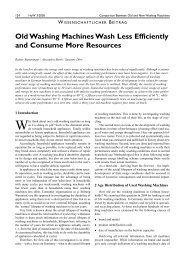
Figure 5.11 Hoeing trajectories <strong>of</strong> the hoeing tool with nine arms in a<br />
field with 300 mm intra-row distance between plants<br />
(arm length 440 mm, angular position <strong>of</strong> all arms<br />
adjusted to 0°, � - position <strong>of</strong> the plant)<br />
The trajectories <strong>of</strong> the duckfoot knives under the soil surface <strong>for</strong> equal length <strong>of</strong><br />
the arms can be optimised by adjustment <strong>of</strong> the angular position <strong>of</strong> the arms θ.<br />
The main advantage <strong>of</strong> this kind <strong>of</strong> fine-tuning is that a small angular change<br />
provides the possibility <strong>of</strong> controlling the distance between consecutive cuts <strong>of</strong><br />
each section. Also, the adjustment <strong>of</strong> the angular position <strong>of</strong> the arms θ affects<br />
the penetration order <strong>of</strong> the front, middle and rear duckfoot knives <strong>of</strong> each<br />
section, <strong>for</strong>wards or backwards, in relation to the z-axis. An example <strong>of</strong> the<br />
<strong>for</strong>ward-backward rearrangement <strong>of</strong> the trajectories by changing the angular<br />
position <strong>of</strong> the front and rear duckfoot knives in each section on the rotary hoe<br />
with nine arms is illustrated in Figures 5.12 and 5.13. The segments <strong>of</strong> the<br />
trajectories under the soil surface are highlighted on both graphs. The expected<br />
crop positions are x=200 mm, 400 mm, 600 mm; y=0 and they are marked with<br />
“+” on the graphics.<br />
fr3<br />
re3<br />
+<br />
fr1<br />
79