Development of a novel mechatronic system for mechanical weed ...
Development of a novel mechatronic system for mechanical weed ...
Development of a novel mechatronic system for mechanical weed ...

You also want an ePaper? Increase the reach of your titles
YUMPU automatically turns print PDFs into web optimized ePapers that Google loves.
Institut für Landtechnik<br />
der Rheinischen Friedrich-Wilhelms-Universität Bonn<br />
<strong>Development</strong> <strong>of</strong> a <strong>novel</strong> <strong>mechatronic</strong> <strong>system</strong> <strong>for</strong><br />
<strong>mechanical</strong> <strong>weed</strong> control <strong>of</strong> the intra-row area in row<br />
crops based on detection <strong>of</strong> single plants and adequate<br />
controlling <strong>of</strong> the hoeing tool in real-time<br />
Inaugural-Dissertation<br />
Zur<br />
Erlangung des akademischen Grades<br />
Doktor der Ingenieurwissenschaften<br />
der<br />
Hohen Landwirtschaftlichen Fakultät<br />
der Rheinischen Friedrich-Wilhelms-Universität<br />
zu Bonn<br />
vorgelegt im November 2007<br />
von<br />
Dipl.-Ing. Maschinenbau M.Sc Zoltan Gobor<br />
aus Apatin (Serbien)
Referent: Pr<strong>of</strong>. Dr.-Ing. P. Schulze Lammers<br />
Korreferent: Pr<strong>of</strong>. Dr.-Ing. habil. Jan-Welm Biermann<br />
Koreferent: Pr<strong>of</strong>. Dr. Milan Martinov<br />
Tag der mündlichen Prüfung: 17.12.2007<br />
© im Selbstverlag<br />
Bezugsquelle: Institut für Landtechnik<br />
Rheinsche Fridrich-Wilhelms-Universität<br />
Nussallee 5<br />
531115 Bonn<br />
Alle Rechte, auch die der Übersetzung und des Nachdruckes sowie jede Art der<br />
photomechanischen Wiedergabe, auch auszugsweise, bleibt vorbehalten.
<strong>Development</strong> <strong>of</strong> a <strong>novel</strong> <strong>mechatronic</strong> <strong>system</strong> <strong>for</strong><br />
<strong>mechanical</strong> <strong>weed</strong> control <strong>of</strong> the intra-row area in row<br />
crops based on detection <strong>of</strong> single plants and adequate<br />
controlling <strong>of</strong> the hoeing tool in real-time<br />
Abstract<br />
As a component <strong>of</strong> successful non-chemical <strong>weed</strong> control intra-row <strong>weed</strong>ing shall be<br />
considered as a final <strong>weed</strong> elimination procedure and not as a primary method.<br />
Conventional methods <strong>for</strong> inter-row <strong>weed</strong> control can handle with approximately 80% <strong>of</strong><br />
the field area in row planted crops and vegetables. However, the <strong>weed</strong>s occur in the<br />
remaining area between (intra-row) and around the plants (close-to-crop) have a much<br />
bigger impact on the development and yield <strong>of</strong> the plants.<br />
Online detection <strong>of</strong> the single plant position and the plant/<strong>weed</strong> distinction are the<br />
bottlenecks <strong>of</strong> intra-row <strong>weed</strong>ing but concerning the expeditious research and<br />
development in this field it is to expect that appropriate <strong>system</strong>s would be available on<br />
the market in near future. In the meantime, construction and adjustment possibilities <strong>of</strong><br />
implements considering the role <strong>of</strong> soil properties and mechanics need to be optimised<br />
toward universal intra-row <strong>weed</strong>ing tools, which can be used in different plant spacing<br />
<strong>system</strong>s, different plant intra-row distances and growth stages.<br />
A virtual prototype <strong>of</strong> a <strong>system</strong> <strong>for</strong> intra-row <strong>weed</strong>ing imitating the manual hoeing<br />
motions under the soil surface was designed. The hoeing tool consists <strong>of</strong> an arm holder<br />
and three or more integrated arms rotating around the horizontal axis above the crop<br />
row. Tests and simulations <strong>of</strong> the hoeing trajectories carried out with the virtual<br />
prototype have increasingly facilitated the design process and significantly shortened<br />
the path from the idea to the prototype. The physical prototype was realised using a<br />
servo motor with direct s<strong>of</strong>tware control providing rotational speed adjustment<br />
according to the <strong>for</strong>ward speed <strong>of</strong> the carrier, intra-row distance between plants and<br />
the observed position <strong>of</strong> the arms.<br />
A simplified methodology and <strong>system</strong> <strong>for</strong> plant position detection based on the spectral<br />
characteristics <strong>of</strong> crop plants combined with the context in<strong>for</strong>mation <strong>of</strong> the planting<br />
pattern was developed and tested. The experimental results showed that the<br />
combination <strong>of</strong> the RGB sensor <strong>for</strong> determination <strong>of</strong> the spectral characteristics and<br />
area covering laser sensor <strong>for</strong> determination <strong>of</strong> height and reflectance can be used <strong>for</strong><br />
accurate detection <strong>of</strong> the plant centre position independently from illumination<br />
conditions. The maximum deviation <strong>of</strong> the estimated centre positions from the plant
Abstract<br />
real centre positions, in experiments conducted with RGB sensor, was 31 mm whereby<br />
50% <strong>of</strong> the samples were inside the interval 0 to 5 mm and 90% <strong>of</strong> the samples were<br />
inside the interval 0 to 16.9 mm. The maximum deviation <strong>of</strong> the estimated centre<br />
positions from the plant real centre positions, in experiments conducted with laser<br />
sensor, was 25 mm whereby 50% <strong>of</strong> the samples were inside the interval 0 to 3 mm<br />
and 90% <strong>of</strong> the samples were inside the interval 0 to 6.9 mm.<br />
The servo <strong>system</strong> built in the physical prototype was operated in a mode with direct<br />
s<strong>of</strong>tware control providing rotational speed adjustment according to the <strong>for</strong>ward speed<br />
<strong>of</strong> the carrier, intra-row distance between successive crop plants and the observed<br />
angular position <strong>of</strong> the arms. The controlling algorithm and s<strong>of</strong>tware solution were<br />
developed in the Labview® environment. The main task <strong>of</strong> the controlling s<strong>of</strong>tware was<br />
permanent calculation, checking and change <strong>of</strong> the recent rotational speed <strong>of</strong> the<br />
hoeing tool in real time. The s<strong>of</strong>tware solution used an extended version <strong>of</strong> the<br />
s<strong>of</strong>tware previously developed <strong>for</strong> detection <strong>of</strong> the plants’ centre position.<br />
Tests have proved that depending on the angular adjustment <strong>of</strong> the arms carrying the<br />
duckfoot knives an uncultivated area big enough to avoid damaging <strong>of</strong> the plants can<br />
be left around the plants during the intra-row <strong>weed</strong>ing with the developed <strong>system</strong>.<br />
The <strong>system</strong> is able to autonomously adapt the rotational speed <strong>of</strong> the hoeing tool in<br />
case <strong>of</strong> non-intensive <strong>for</strong>ward speed change. After rapid <strong>for</strong>ward speed change,<br />
several plants can be damaged while the <strong>system</strong> stabilises its work, but stable state<br />
can be reached immediately after the stabilisation period.<br />
The presented concept <strong>of</strong> the intra-row hoeing <strong>system</strong> can fulfil the requirements; it has<br />
sufficient degrees <strong>of</strong> freedom to allow full adaptation to different crop and vegetable<br />
species, different plant intra-row distances and plant growth stages. In combination<br />
with an inter-row hoe or installed on an autonomous vehicle, the developed robotic<br />
<strong>system</strong> could be a solution <strong>for</strong> accurate and rapid <strong>mechanical</strong> <strong>weed</strong> control.
Kurzfassung<br />
Entwicklung eines neuartigen mechatronischen Systems<br />
für die mechanische Unkrautbekämpfung in der Reihe<br />
basierend auf der Erkennung von Einzelpflanzen und<br />
adäquaten Regelung der Hackwerkzeuge in Echtzeit<br />
Als ein Bestandteil einer erfolgreichen nicht chemischen Unkrautbekämpfung soll die<br />
Unkrautbekämpfung in der Reihe das Verfahren vervollständigen und nicht als eine<br />
primäre Methode angesehen werden. Die konventionelle Maschinenhacke zwischen<br />
den Reihen deckt ca. 80 % der Fläche in Reihenfrüchten ab. Unkräuter treten jedoch in<br />
der Reihe zwischen den Pflanzen (intra-row) und nahe bei den Pflanzen auf (close-to-<br />
crop) und haben dort einen größeren Einfluss auf die Entwicklung der Nutzpflanzen.<br />
Die Online Erkennung der Position einzelner Pflanzen und die Unterscheidung<br />
Nutzpflanze-Unkraut sind die Hauptprobleme einer mechanischen Unkrautbekämpfung<br />
in der Reihe. Auf Grund der umfangreichen Forschungs- und Entwicklungsaktivitäten in<br />
diesem Bereich wird jedoch erwartet, dass solche Systeme in naher Zukunft verfügbar<br />
sein werden. In der Zwischenzeit kann die Weiterentwicklung von universellen<br />
Hackgeräten für den Bereich in der Reihe, die für unterschiedliche Pflanzenabstände<br />
und Entwicklungsstadien eingesetzt werden können, stattfinden.<br />
Es wurde ein virtueller Prototyp für die Unkrautbekämpfung in der Reihe entwickelt, der<br />
die Bewegung der manuellen Hacke im Boden imitiert. Das Hackwerkzeug besteht aus<br />
einem Armträger und drei oder mehr daran befestigten Armen, die um die horizontale<br />
Achse, die sich oberhalb der Pflanzenreihe befindet, rotieren. Tests und Simulationen<br />
der Bewegungsbahnen der Hackwerkzeuge, die mit dem virtuellen Prototyp<br />
durchgeführt wurden, haben den Entwicklungsprozess zunehmend verbessert und den<br />
Entwicklungsweg von der Idee zum Prototyp erheblich beschleunigt. Ein physikalischer<br />
Prototyp wurde mit einem Servomotor, der über die Betriebss<strong>of</strong>tware die Drehzahl in<br />
Abhängigkeit von der Vorfahrtsgeschwindigkeit, dem Pflanzenabstand in der Reihe und<br />
der Winkelposition der Hackarme regelt, realisiert.<br />
Zusätzlich wurde eine Methode und ein System zur Erkennung der Position der<br />
Nutzpflanzen basierend auf deren spektralen Eigenschaften, kombiniert mit der<br />
In<strong>for</strong>mation über die Geometrie der Saatgutablage entwickelt und getestet. Die<br />
experimentellen Ergebnisse zeigen, dass die Kombination eines RGB Sensors für<br />
Ermittlung den spektralen Eigenschaften Laser Sensor für Ermittlung der<br />
Pflanzenhöhe, für eine präzise Erkennung der Mittelpunktsposition der Nutzpflanzen
Kurzfassung<br />
verwendet werden kann und unabhängig von den Lichtverhältnissen arbeitet. In den<br />
Versuchen betrug die maximale Abweichung des geschätzten Pflanzenmittelpunktes<br />
von dem gemessenen Mittelpunkt, ermittelt von dem RGB Sensor, 31 mm, wobei 50 %<br />
der Werte in einem Intervall von 0 bis 5 mm und 90 % der Werte in einem Intervall von<br />
0 bis 16,9 mm lagen. Für den Laserabstandssensor lag die maximale Abweichung der<br />
geschätzten von den gemessenen Werten bei 25 mm, wobei in einem Intervall von 0<br />
bis 3 mm 50 % der Werte und 90 % der Werte in einem Intervall von 0 bis 6, 9 mm<br />
lagen.<br />
Der Servomotor, der in dem Prototyp eingebaut war, wurde in einer Betriebsweise mit<br />
direkter S<strong>of</strong>twareregelung betrieben, die die Anpassung der Drehgeschwindigkeit<br />
entsprechend der Vorfahrtsgeschwindigkeit, dem Abstand der Pflanzen in der Reihe<br />
und der aktuellen Position der Hackarme vornimmt. Der Regelalgorithmus und die<br />
S<strong>of</strong>tware wurden mit Labview® erstellt. Die Hauptaufgabe des Regelalgorithmus ist die<br />
permanente Berechnung und Prüfung sowie Änderung der aktuellen<br />
Drehgeschwindigkeit des Hackorgans in Echtzeit. Die S<strong>of</strong>tware basiert auf einer<br />
Erweiterung der S<strong>of</strong>tware, die vorher für die Pflanzenerkennung benutzt wurde.<br />
Tests haben bestätigt, dass abhängig von Winkeleinstellung der Hackarme ein<br />
ausreichend unbearbeiteter Bereich um die Nutzpflanzen während des Hackvorganges<br />
in der Reihe belassen wird, um die Schädigung von Wurzeln durch das Hack<strong>system</strong> zu<br />
vermeiden.<br />
Das System ist in der Lage selbständig die Drehgeschwindigkeit des Hackwerkzeuges<br />
für den Fall nicht abrupter Geschwindigkeitsänderungen anzupassen. Nach einer<br />
schnellen Geschwindigkeitsänderung können einige Nutzpflanzen beschädigt werden<br />
bis das System wieder stabil arbeitet. Ein stabiler Zustand kann unmittelbar nach der<br />
Stabilisierungsperiode erreicht werden.<br />
Das dargestellte Konzept einer INTRA-Reihenhacke kann die gestellten An<strong>for</strong>derungen<br />
erfüllen, es verfügt über ausreichend Freiheitsgrade, um die volle Anpassung an<br />
verschiedene Pflanzenarten, verschiedene Pflanzenabstände in der Reihe und<br />
Entwicklungsstadien der Nutzpflanzen zu erreichen.
Acknowledgements<br />
Acknowledgements<br />
Many people contributed, directly or indirectly, in shaping up my academic career and<br />
make it possible to complete this thesis. Here is a small tribute to all <strong>of</strong> them.<br />
First <strong>of</strong> all I would like to express my gratitude to Pr<strong>of</strong>. Dr.-Ing. Peter Schulze Lammers<br />
my academic supervisor, who gave me the opportunity to become a member <strong>of</strong> the<br />
DFG Research Training Group GK 722 and study at the University <strong>of</strong> Bonn. I would like<br />
to thank him <strong>for</strong> his help from the very beginning <strong>of</strong> my application onward, <strong>for</strong> his<br />
constant encouragement and <strong>for</strong> giving me full autonomy throughout the entire time <strong>of</strong><br />
my studies. His many helpful suggestions, detailed comments and critical reading <strong>of</strong><br />
the manuscript were crucial <strong>for</strong> completing my thesis within a timeframe <strong>of</strong> 3 years. I<br />
really appreciate the trust he had in me.<br />
I am also grateful to Pr<strong>of</strong>. Dr. Milan Martinov because our cooperation and wide<br />
ranging discussions which were not only about the scientific topics introduced me the<br />
funny side <strong>of</strong> the academic life. I am deeply indebted <strong>for</strong> his moral and all other types <strong>of</strong><br />
supports during my M. Sc studies in Novi Sad. Pr<strong>of</strong>essor Martinov was one <strong>of</strong> the main<br />
driving <strong>for</strong>ces that I started an international academic carrier. I appreciate his<br />
willingness to be on my examination committee.<br />
I also take this opportunity to express my special gratitude to Pr<strong>of</strong>. Dr. Mirjana Vojinovic<br />
– Miloradov without whose support I would never have reached this point. I owe her<br />
more than I could express here. Thanks to the academic staff <strong>of</strong> the Faculty <strong>of</strong><br />
Technical Sciences in Novi Sad <strong>for</strong> supporting my idea to continue my studies in<br />
Germany.<br />
I am grateful <strong>for</strong> the valuable financial help that I have received from Dr. Erich-<br />
Christian Oerke, coordinator <strong>of</strong> the DFG Research Training Group 722, from the<br />
beginning onward <strong>for</strong> development <strong>of</strong> the prototype, attending scientific conferences<br />
and German language classes. In particular, I would like to thank him <strong>for</strong> his critical<br />
reading <strong>of</strong> the manuscript and suggestions.<br />
I wish to express my sincere gratitude to Pr<strong>of</strong>. Dr.-Ing. habil. Jan-Welm Biermann, my<br />
second supervisor, <strong>for</strong> allowing his precious time to read the manuscript.<br />
I would like also to express my appreciation to Dr.-Ing. Lutz Damerow <strong>for</strong> his<br />
stimulating support, advices and very useful discussions.
Acknowledgements<br />
My thanks and appreciation goes to Dan <strong>for</strong> his pro<strong>of</strong>reading <strong>of</strong> the work and valuable<br />
support that I received while conducting the experiments.<br />
I would like to acknowledge the financial support <strong>of</strong> this project by the German Science<br />
Foundation (DFG).<br />
I am privileged <strong>for</strong> having Oliver, Istvan, Olaf and both <strong>of</strong> my <strong>of</strong>fice mates Jiri and<br />
Peter, my colleges, who have provided great company during last three years. Thanks<br />
to Simone and Daniel <strong>for</strong> the grill parties and being great volleyball partners. Manny<br />
thanks to Miss Frauke Beeken <strong>for</strong> assisting me to understand and exceed the<br />
administrative and German language difficulties.<br />
Thanks to the staff <strong>of</strong> the workshop: Mr Dreesen <strong>for</strong> helping me during the<br />
development <strong>of</strong> the electronics, Mr Berg <strong>for</strong> the discussions and introduction <strong>of</strong> the<br />
historical development <strong>of</strong> the sugar beet cultivating <strong>system</strong>s, useful contributions <strong>of</strong> Mr<br />
Berchtold and Mr Petriwski at various times during the development <strong>of</strong> the physical<br />
prototype and Mr Dürkop providing technical support during the field experiments.<br />
Special thanks to my uncles Georg and Ladislav Lampert and their families <strong>for</strong><br />
continuous taking care <strong>of</strong> me, to not suffer in any shortages and let me feel that I am<br />
not far away from my family.<br />
Thanks to Mr. Karl-Martin Schmidt-Reindl who hosted me during my first month <strong>of</strong><br />
staying in Bonn.<br />
I wish to thank my parents, Katalin and Josip Gobor, <strong>for</strong> their continuous moral support<br />
and encouragement in all my pr<strong>of</strong>essional endeavours. Finally, I wish to express my<br />
gratitude and thanks to my wonderful wife Sara that she postponed her career and<br />
provided love, understanding and patience while I ‘played in the lab with the <strong>weed</strong>er’.<br />
I dedicate this thesis to my family
Table <strong>of</strong> contents<br />
Table <strong>of</strong> contents<br />
Glossary <strong>of</strong> abbreviations and symbols........................................................................ I<br />
1 Introduction .............................................................................................................................. 1<br />
1.1 Consumption <strong>of</strong> chemicals in agriculture............................................................................ 3<br />
1.1.1 Impact <strong>of</strong> pesticide application on groundwater sources ............................................ 6<br />
1.2 Organic farming .................................................................................................................. 7<br />
1.3 Weed management............................................................................................................. 9<br />
1.4 Organic <strong>weed</strong> management.............................................................................................. 10<br />
1.4.1 Indirect <strong>weed</strong> control ................................................................................................. 11<br />
1.4.2 Direct <strong>weed</strong> control.................................................................................................... 14<br />
1.4.3 Inter-row <strong>weed</strong> control............................................................................................... 15<br />
2 State <strong>of</strong> the art ........................................................................................................................ 19<br />
2.1 Intra-row <strong>weed</strong> control ...................................................................................................... 19<br />
2.1.1 Passive tools <strong>for</strong> intra-row <strong>weed</strong> control.................................................................... 19<br />
2.1.2 Active tools <strong>for</strong> intra-row <strong>weed</strong> control ...................................................................... 21<br />
2.2 Detection <strong>of</strong> the plants ...................................................................................................... 26<br />
3 Definition <strong>of</strong> the problem and research objectives ............................................................ 29<br />
3.1 Definition <strong>of</strong> the problem................................................................................................... 29<br />
3.2 Research objectives.......................................................................................................... 31<br />
4 Materials and methods .......................................................................................................... 33<br />
4.1 Detection <strong>of</strong> the single plant position................................................................................ 33<br />
4.1.1 Sensor equipment ..................................................................................................... 33<br />
4.1.1.1 Digital colour sensor........................................................................................... 33<br />
4.1.1.2 Digital laser sensor............................................................................................. 35<br />
4.1.1.3 Forward position detection................................................................................. 37<br />
4.1.1.4 Position sensor with incremental encoder ......................................................... 37<br />
4.1.1.5 Rotary encoder position sensor ......................................................................... 38<br />
4.1.2 Data acquisition ......................................................................................................... 39<br />
4.1.2.1 Hardware............................................................................................................ 39<br />
4.1.2.2 S<strong>of</strong>tware ............................................................................................................. 39<br />
4.1.3 Experimental field ...................................................................................................... 40<br />
4.1.4 Test objects ............................................................................................................... 41<br />
4.1.5 Test <strong>of</strong> the detection <strong>system</strong>’s accuracy ................................................................... 41<br />
4.1.6 Test <strong>of</strong> the detection <strong>system</strong>’s robustness ................................................................ 41<br />
4.2 The use <strong>of</strong> integrated mechanism design and simulation in prototype development....... 42<br />
4.2.1 Introduction to prototypes.......................................................................................... 42<br />
4.2.2 Advantages <strong>of</strong> virtual prototyping .............................................................................. 43<br />
4.2.2.1 Pro/Engineer as a s<strong>of</strong>tware tool......................................................................... 45<br />
4.3 Physical prototype <strong>of</strong> the hoeing tool................................................................................ 48<br />
4.3.1 Selection <strong>of</strong> the drive <strong>for</strong> the hoeing tool................................................................... 48<br />
4.3.1.1 Electrical servo drive .......................................................................................... 48<br />
4.3.1.2 Power transmission............................................................................................ 51<br />
4.3.1.3 Adjustment <strong>of</strong> the parameters <strong>of</strong> the servo drive ............................................... 52
Acknowledgements<br />
5 Results and discussion ......................................................................................................... 57<br />
5.1 Algorithm <strong>for</strong> detection <strong>of</strong> the plant centre position........................................................... 57<br />
5.1.1 Evaluation <strong>of</strong> the algorithm <strong>for</strong> detection <strong>of</strong> the plant centre position........................ 61<br />
5.1.2 Results <strong>of</strong> the accuracy test....................................................................................... 63<br />
5.1.3 Results <strong>of</strong> the robustness test ................................................................................... 65<br />
5.1.4 Discussion <strong>of</strong> the plant centre position detection methodology................................. 70<br />
5.2 Virtual prototype <strong>of</strong> the rotary hoe <strong>for</strong> intra-row <strong>weed</strong>ing.................................................. 71<br />
5.2.1 Optimisation <strong>of</strong> the arm length................................................................................... 76<br />
5.2.2 Examination <strong>of</strong> influences <strong>of</strong> the angular position θ to the hoeing trajectories ......... 77<br />
5.2.3 Examination <strong>of</strong> influences <strong>of</strong> the ratio between the rotational speed <strong>of</strong> the hoeing tool<br />
and the <strong>for</strong>ward speed <strong>of</strong> the carrier................................................................................... 82<br />
5.2.4 Selection <strong>of</strong> appropriate design <strong>of</strong> the hoeing tool according to the hoeing scenario84<br />
5.2.5 Discussion <strong>of</strong> the results conducted by virtual prototyping........................................ 86<br />
5.3 Physical prototype <strong>of</strong> the hoeing equipment..................................................................... 87<br />
5.3.1 Determination <strong>of</strong> the maximum torque and nominal speed required......................... 87<br />
5.3.2 Calculation and selection <strong>of</strong> the motor and transmission combination ..................... 89<br />
5.3.2.1 External control <strong>of</strong> the rotational speed.............................................................. 90<br />
5.3.3 Discussion <strong>of</strong> the distance between the plant detection unit and the plane in which<br />
the hoeing tool is positioned ............................................................................................... 91<br />
5.3.4 Algorithm <strong>for</strong> the online control <strong>of</strong> the hoeing tool’s rotational speed........................ 96<br />
5.3.5 Test bench <strong>for</strong> evaluation <strong>of</strong> the intra-row hoeing tool .............................................. 99<br />
5.3.6 Methodology <strong>for</strong> evaluation <strong>of</strong> the algorithm <strong>for</strong> online control <strong>of</strong> the hoeing tool... 102<br />
5.3.7 Evaluation <strong>of</strong> the algorithm <strong>for</strong> online control <strong>of</strong> the hoeing tool by experimental<br />
testing ............................................................................................................................... 103<br />
6 Summary ............................................................................................................................... 121<br />
7 Conclusions .......................................................................................................................... 125<br />
Further work ............................................................................................................. 125<br />
8 References ............................................................................................................................ 127<br />
9 Appendix ............................................................................................................................... 139<br />
List <strong>of</strong> figures............................................................................................................ 135<br />
List <strong>of</strong> tables ............................................................................................................. 138
Glossary <strong>of</strong> abbreviations and symbols<br />
Symbol Unit Description<br />
Glossary <strong>of</strong> abbreviations and symbols<br />
.NET <strong>Development</strong> environment built <strong>for</strong> the .NET Framework<br />
A Austria<br />
C<br />
CAD Computer aided design<br />
General-purpose, block structured, procedural, imperative<br />
computer programming language<br />
CAE Computer aided engineering<br />
CAM Computer aided manufacturing<br />
CPU Central processing unit (processor)<br />
D Germany<br />
d m Average distance between plants<br />
Dpulley<br />
Dsens-hoe<br />
m<br />
DAQ Data acquisition<br />
DC<br />
Diameter <strong>of</strong> the pulley assembled to the rotary encoder <strong>for</strong><br />
<strong>for</strong>ward position detection<br />
Distance between the plant detection unit and the plane in<br />
which the hoeing tool is positioned<br />
Direct current (electricity) - the flow <strong>of</strong> electric charge is<br />
constant<br />
DDT Dichlordiphenyltrichlorethan C14H9Cl5<br />
dp m<br />
E Spain<br />
Diameter <strong>of</strong> the uncultivated area around the plant after <strong>weed</strong><br />
control with intra-row <strong>weed</strong>ing <strong>system</strong><br />
ECNC European centre <strong>for</strong> nature conservation<br />
EMPP Estimated middle point <strong>of</strong> the plant<br />
EU European Union<br />
I
Glossary <strong>of</strong> abbreviation and symbols<br />
Symbol Unit Description<br />
EUREAU<br />
II<br />
European union <strong>of</strong> national associations <strong>of</strong> water suppliers<br />
and waste water services<br />
EUROSTAT Statistical <strong>of</strong>fice <strong>of</strong> the European communities<br />
F France<br />
Fr front<br />
G Gear ratio<br />
GAP The concept <strong>of</strong> good agricultural practices<br />
GPS Global positioning <strong>system</strong><br />
hdmin m Minimum hoeing depth<br />
hdmax m Maximum hoeing depth<br />
hw1 m Hoeing width which corresponds to minimum hoeing depth<br />
hw2 Hoeing width which corresponds to maximum hoeing depth<br />
I Italy<br />
I/O Input - output<br />
IUCN The World conservation union<br />
JL kg m 2 Inertia <strong>of</strong> the load<br />
JM kg m 2 Inertia <strong>of</strong> the motor<br />
Lsen m Maximum detecting range <strong>of</strong> the sensor<br />
MA Nm Acceleration torque<br />
MD Nm Deceleration torque<br />
MF Nm Friction torque<br />
Mhmaxexp<br />
Nm<br />
Maximal torque measured on the hoeing tool’s shaft during<br />
field experiments<br />
Mhn Nm Nominal torque <strong>of</strong> the hoeing tool
Symbol Unit Description<br />
Mmmax Nm Maximal torque <strong>of</strong> the servo motor<br />
Mmn Nm Nominal torque <strong>of</strong> the servo motor<br />
Min Nm Torque <strong>of</strong> the gearbox input shaft<br />
Mout Nm Torque <strong>of</strong> the gearbox output shaft<br />
Glossary <strong>of</strong> abbreviations and symbols<br />
M-file Script file which contains Matlab commands<br />
mi Middle<br />
N Nitrogen<br />
N pulse<br />
NI National Instruments<br />
NL Netherlands<br />
OS Operating <strong>system</strong><br />
P W Phosphorus<br />
Value acquired with incremental encoder corresponding to the<br />
latest angular position <strong>of</strong> the hoeing tool<br />
Pin W Power on the gearbox input shaft<br />
Pout W Power on the gearbox output shaft<br />
Prequred W Required power <strong>of</strong> the hoeing tool<br />
PFM Pulse frequency modulation<br />
PMCD Permanent magnet direct current<br />
PWM Pulse width modulation<br />
RLA<br />
Rfront<br />
Rrear<br />
m<br />
m<br />
m<br />
Distance between the hoeing tool’s rotational axis and the<br />
joint between the <strong>for</strong>earm and upper arm <strong>of</strong> the hoeing tool<br />
Estimated distance between the duckfoot knife’s blade<br />
approaching the plant from the front side and the centre<br />
position <strong>of</strong> the plant<br />
Estimated distance between the duckfoot knife’s blade<br />
approaching the plant from the rear side and the centre<br />
position <strong>of</strong> the plant<br />
III
Glossary <strong>of</strong> abbreviation and symbols<br />
Symbol Unit Description<br />
RUA<br />
IV<br />
m<br />
Distance between the joint between the <strong>for</strong>earm and upper<br />
arm <strong>of</strong> the hoeing tool and the cutting edge <strong>of</strong> the duckfoot<br />
knife placed on the upper arm<br />
RESsys ppr Resolution <strong>of</strong> the hoeing tool<br />
Re Rear<br />
RGB<br />
Colour model in which red, green, and blue are combined in<br />
various ways to reproduce other colours<br />
RTK-GPS Real time kinematic global positioning <strong>system</strong><br />
∆s m Sampling distance<br />
SL Standard deviation <strong>of</strong> the data acquired with the laser sensor<br />
SRGB Standard deviation <strong>of</strong> the data acquired with the RGB sensor<br />
SA Searching area<br />
SCR Silicon controlled rectifier<br />
SR m Sampling distance<br />
T s<br />
Tmin<br />
s<br />
∆t s Change <strong>of</strong> the time<br />
tL<br />
tL-1<br />
s<br />
s<br />
Estimated time in which the hoeing tool arrives exactly above<br />
the following plant centre position<br />
Time in which one full rotation <strong>of</strong> the <strong>system</strong> can be achieved<br />
with rated rotational speed<br />
Absolute time value in which the plant detection unit was<br />
positioned exactly above the centre position <strong>of</strong> the latest plant<br />
Absolute time value in which the plant detection unit was<br />
positioned exactly above the centre position <strong>of</strong> the latest but<br />
one plant<br />
TTL Transistor–transistor logic<br />
TGSS True ground speed sensor<br />
∆u rpm Change <strong>of</strong> the rotational speed<br />
uhmax rpm Maximum rotational speed <strong>of</strong> the hoeing tool
Symbol Unit Description<br />
Glossary <strong>of</strong> abbreviations and symbols<br />
uhn rpm Nominal rotational speed <strong>of</strong> the hoeing tool<br />
ummax rpm Maximum rotational speed <strong>of</strong> the servo motor<br />
unew rpm Newly calculated rotational speed <strong>of</strong> the hoeing tool<br />
uold rpm Latest rotational speed <strong>of</strong> the hoeing tool<br />
UK United Kingdom<br />
USB Universal serial bus<br />
V m s -1<br />
Vmax<br />
m s -1<br />
Forward speed <strong>of</strong> the hoeing tool<br />
Maximum <strong>for</strong>ward speed <strong>for</strong> the hoeing <strong>system</strong> with three<br />
arms and hoeing strategy when one full rotation corresponds<br />
to three cuts between every two plants in the row<br />
VI Virtual instrument (LabVIEW)<br />
VE Virtual environment<br />
VP Virtual prototyping<br />
xfr1<br />
xfront<br />
xmi1<br />
xre1<br />
xrear<br />
yfr1<br />
ymi1<br />
m<br />
m<br />
m<br />
m<br />
m<br />
m<br />
m<br />
Projection <strong>of</strong> the 1 section’s front duckfoot knife position to xaxis<br />
Projection <strong>of</strong> the distance between the duckfoot knife’s blade<br />
approaching the plant from the front side and the centre<br />
position <strong>of</strong> the plant to x-axis<br />
Projection <strong>of</strong> the 1 section’s middle duckfoot knife position to<br />
x-axis<br />
Projection <strong>of</strong> the 1 section’s rear duckfoot knife position to xaxis<br />
Projection <strong>of</strong> the distance between the duckfoot knife’s blade<br />
approaching the plant from the rear side and the centre<br />
position <strong>of</strong> the plant to x-axis<br />
Projection <strong>of</strong> the 1 section’s front duckfoot knife position to yaxis<br />
Projection <strong>of</strong> the 1 section’s middle duckfoot knife position to<br />
y-axis<br />
V
Glossary <strong>of</strong> abbreviation and symbols<br />
Symbol Unit Description<br />
yre1<br />
zfr1<br />
zfront<br />
zmi1<br />
zre1<br />
zrear<br />
VI<br />
m<br />
m<br />
m<br />
m<br />
m<br />
Projection <strong>of</strong> the 1 section’s rear duckfoot knife position to yaxis<br />
Projection <strong>of</strong> the 1 section’s front duckfoot knife position to zaxis<br />
Projection <strong>of</strong> the distance between the duckfoot knife’s blade<br />
approaching the plant from the front side and the centre<br />
position <strong>of</strong> the plant to z-axis<br />
Projection <strong>of</strong> the 1 section’s middle duckfoot knife position to<br />
z-axis<br />
Projection <strong>of</strong> the 1 section’s rear duckfoot knife position to zaxis<br />
Projection <strong>of</strong> the distance between the duckfoot knife’s blade<br />
approaching the plant from the rear side and the centre<br />
position <strong>of</strong> the plant to z-axis<br />
z(t) m Absolute position <strong>of</strong> the plant detection unit<br />
zc(tL) m<br />
zc(tL-1) m<br />
Absolute coordinate <strong>of</strong> the last detected plant’s centre position<br />
in direction <strong>of</strong> travelling<br />
absolute coordinate <strong>of</strong> the last but one detected plant’s centre<br />
position in direction <strong>of</strong> traveling<br />
α rad s -2 Acceleration <strong>of</strong> the motor<br />
∆ ° Angle between <strong>for</strong>earms implemented on an arm holder<br />
Ε °<br />
Angle between the axis <strong>of</strong> symmetry <strong>of</strong> the duckfoot knife and<br />
the plane in which the arm holder is placed<br />
Φ rad Angular position <strong>of</strong> the hoeing tool<br />
φrecent rad Latest angular position <strong>of</strong> the hoeing tool<br />
η Coefficient <strong>of</strong> efficiency (gearbox)<br />
Θ °<br />
ωin<br />
ωnew<br />
Angle <strong>of</strong> the hoeing arms in relation to the plane<br />
perpendicular to the rotation axis in which the arm holder is<br />
placed<br />
rad s -2 Angular speed <strong>of</strong> the gearbox input shaft<br />
rad s -2 Newly calculated rotational speed <strong>of</strong> the hoeing tool
ωold<br />
ωout<br />
rad s -2 Latest rotational speed <strong>of</strong> the hoeing tool<br />
rad s -2 Angular speed <strong>of</strong> the gearbox output shaft<br />
Glossary <strong>of</strong> abbreviations and symbols<br />
VII
1 Introduction<br />
Introduction<br />
Scientifically and socially it is recognised that sustainable development,<br />
particularly in the agricultural sector cannot be based on the intensive<br />
application <strong>of</strong> agrochemicals. Production techniques need to be trans<strong>for</strong>med<br />
toward <strong>system</strong>s with low or no input <strong>of</strong> pesticides. However, there are opposing<br />
requirements and conflicts between agricultural production and society<br />
concerning pesticide application. The consumers should be supplied with high<br />
quality and healthy food products which have an acceptable price and are<br />
available during the whole year. Additionally, agricultural products and<br />
foodstuffs should be produced without any negative impact on the environment.<br />
On the other hand, farmers are interested in attaining high crop yield and pr<strong>of</strong>it<br />
maximisation, meaning low production costs and high prices <strong>of</strong> their products<br />
on the market. However, these are diametrically opposed requirements<br />
according to the application <strong>of</strong> chemicals in agriculture. One <strong>of</strong> possible<br />
solutions is organic farming, but average yield in these <strong>system</strong>s is lower than in<br />
conventional farms and thus the price <strong>of</strong> the products is higher. The input <strong>of</strong><br />
manual labour in general, and especially <strong>for</strong> <strong>weed</strong> control, is undoubtedly higher<br />
in organic farming, which is the major drawback <strong>of</strong> this production method<br />
(Stonehouse et al. 1996; Clark et al. 1999; Nilsson et al. 2000).<br />
Weeds, as one <strong>of</strong> the most significant factors in yield quality and quantity<br />
decrease (Oerke and Steiner 1996; Schans et al 2006), demand a holistic and<br />
interdisciplinary approach <strong>for</strong> their adequate control. It is known that <strong>weed</strong>s not<br />
only lower the yields, but they constitute one <strong>of</strong> the most important means <strong>of</strong><br />
spread and survival <strong>of</strong> crop pathogens. In many cases <strong>weed</strong>s have been found<br />
as symptomless carriers <strong>of</strong> vector-borne viruses. Considerning the worldwide<br />
average, about 10% <strong>of</strong> losses <strong>of</strong> the total yield are caused by <strong>weed</strong>s (Agrios<br />
1988). The greatest danger is caused by <strong>weed</strong>s which are closely allied to crop<br />
plants and carry infections in seasons in which crops are either not grown or are<br />
particularly susceptible (Palti 1981). Theoretically, <strong>weed</strong>s can benefit the<br />
biodiversity by increasing the number <strong>of</strong> species and attracting wild animals, but<br />
this aspect is not significant concerning contemporary agricultural production.<br />
1
Introduction<br />
The most frequently used methods <strong>of</strong> <strong>weed</strong> elimination today are chemical<br />
treatment with herbicides and physical treatment, particularly <strong>mechanical</strong><br />
hoeing. Mechanical <strong>weed</strong> control is an alternative and a supplement to chemical<br />
<strong>weed</strong> control, frequently utilised in row crops. With regard to environmental<br />
impacts, <strong>mechanical</strong> hoeing is preferable to the application <strong>of</strong> herbicides.<br />
The requirement <strong>for</strong> non-chemical <strong>weed</strong> control techniques increases steadily<br />
since the last decade <strong>of</strong> the 20 th century, especially in the Western European<br />
countries, as a consequence <strong>of</strong> the high pollution <strong>of</strong> the underground water<br />
sources, originated by the pesticides. Another reason why non-chemical<br />
<strong>weed</strong>ing is in the limelight nowadays is increased interest in organically<br />
produced agricultural products and foodstuffs. In the EU-Regulation 2092/91 it<br />
is firmly stated that only non-chemical <strong>weed</strong> control can be used in organic<br />
farming.<br />
Concerning demands in non-chemical pest control the following<br />
recommendations <strong>for</strong> further research and development are given (Fogelberg<br />
2001):<br />
2<br />
� research on development <strong>of</strong> alternative methods <strong>of</strong> pest control<br />
which are economically competitive with pesticides;<br />
� research on new techniques/methods <strong>for</strong> physical <strong>weed</strong> control;<br />
� development <strong>of</strong> self-propelled <strong>weed</strong>ing robots;<br />
� development <strong>of</strong> new pest-preventive cropping strategies and<br />
� development <strong>of</strong> new pest-resistant crop varieties.<br />
In row crops approximately 80% <strong>of</strong> the field can be covered by conventional<br />
<strong>mechanical</strong> methods <strong>for</strong> inter-row <strong>weed</strong> control (Nørremark and Griepentrog<br />
2004). Un<strong>for</strong>tunately, the <strong>weed</strong>s occurring in the remaining area between (intra-<br />
row) and around the crop plants (close-to-crop) have a much bigger impact on<br />
the plant development and yield. The mechanisation <strong>of</strong> the intra-row area<br />
cultivation is a complex task and as a result, hand <strong>weed</strong>ing is still the most<br />
frequently used method <strong>of</strong> intra-row <strong>weed</strong> control.
Introduction<br />
According to the particular requirements <strong>for</strong> <strong>mechanical</strong> <strong>weed</strong> control within the<br />
row in row crops, further research and development should be carried out in:<br />
� detection <strong>of</strong> the crop and <strong>weed</strong> plants, determining <strong>weed</strong> density and<br />
species; able to provide in<strong>for</strong>mation about the exact position <strong>of</strong> every<br />
individual plant in real-time;<br />
� non-chemical methods <strong>of</strong> <strong>weed</strong> control fully adaptable to different<br />
crop sowing patterns and use <strong>of</strong> precisely guided energy delivering<br />
<strong>system</strong>s;<br />
� autonomous guided vehicles able to carry the <strong>weed</strong>ing tool and<br />
supply it with energy.<br />
One <strong>of</strong> the <strong>for</strong>midable challenges <strong>for</strong> <strong>mechanical</strong> <strong>weed</strong> control research is to<br />
improve the selectivity <strong>of</strong> tools working close to (or in) the crop row, as also to<br />
optimise construction and adjustment possibilities <strong>of</strong> implements considering<br />
the role <strong>of</strong> soil properties and required <strong>mechanical</strong> characteristics <strong>of</strong> the tool<br />
itself (Kurstjens 1998). With most <strong>mechanical</strong> <strong>weed</strong>ing implements available on<br />
the market, operator skill, experience and knowledge are critical to success<br />
(Bond et al. 2003).<br />
1.1 Consumption <strong>of</strong> chemicals in agriculture<br />
The use <strong>of</strong> pesticides in their various <strong>for</strong>ms has existed almost as long as the<br />
practice <strong>of</strong> agriculture. Historically, many substances, we today know to be<br />
harmful to humans, have been used in agriculture to eliminate unwanted plants<br />
and animals: sulphur, arsenic, lead arsenate, mercury and many others. The<br />
discovery <strong>of</strong> the extraordinary killing effect and endurance to time and weather<br />
conditions <strong>of</strong> DDT in the early 1940's started a new era <strong>of</strong> intensive pesticide<br />
application. In the same time <strong>for</strong>mulation and distribution <strong>of</strong> many other<br />
chemical pesticides began suddenly. In 1944 the first selective herbicides,<br />
composed <strong>of</strong> phenoxy acetic acids, were discovered. In the decades that<br />
followed, more and more synthetic pesticides were created and better<br />
application methods were implemented. In the 1950/60’s, granular herbicides<br />
allowed easier application into the soil. According to the development, pesticide<br />
3
Introduction<br />
application that had previously been limited to small fields with high value crops<br />
has been introduced into the mainstream <strong>of</strong> major field crops and became the<br />
standard practice in the 1970's.<br />
Realizing the negative influences <strong>of</strong> agrochemicals on the environment as a<br />
global eco<strong>system</strong>, awareness and concern about their use have increased in<br />
the past twenty years. Accordingly, the EU has taken legislative steps to limit<br />
the future use <strong>of</strong> pesticides. In the context, particular definition <strong>of</strong> pesticides<br />
includes pesticides, herbicides, fungicides, different growth regulators and other<br />
substances. In 1991, the EU Directive 91/414 was introduced, providing a<br />
common method <strong>for</strong> evaluation <strong>of</strong> the pesticides approval according to their<br />
safety. Currently there is a list <strong>of</strong> 1,026 active ingredients which are being<br />
thoroughly tested and hundreds have already been banned.<br />
The Statistical Office <strong>of</strong> the European Communities - EUROSTAT, collects and<br />
keeps many in<strong>for</strong>mation about the use <strong>of</strong> pesticides over the past fifteen years.<br />
It recorded that the sales <strong>of</strong> active pesticide ingredients within the EU countries<br />
in 1992 totalled 295,173 t (DRAFT EXPLANATORY MEMORANDUM 2002).<br />
This number rose further to 322,315 t in 1998 (DRAFT EXPLANATORY<br />
MEMORANDUM 2002), 332,806 t in 2000, and sank to 327,280 t in 2002<br />
(EUROSTAT 2006).<br />
4<br />
Active ingedient [t]<br />
125,000<br />
120,000<br />
115,000<br />
110,000<br />
105,000<br />
100,000<br />
95,000<br />
90,000<br />
85,000<br />
1991 1992 1993 1994 1995 1996 1997 1998 1999 2000 2001<br />
[Year]<br />
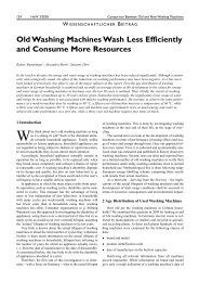
Figure 1.1 Total quantity <strong>of</strong> herbicides sold in the 15 EU states in<br />
the period from 1992 to 2001 (EUROSTAT 2006)
Introduction<br />
The largest purchaser <strong>of</strong> pesticides in 2002 was France, with 99,635 t, followed<br />
closely by Italy with 94,711 t. In the period 1992-2000, average annual increase<br />
in use <strong>of</strong> pesticides was steady at about 1.6%. Between 2000 and 2002,<br />
consumption actually fell by just under 1% each year. Among other active<br />
substances, pesticides include herbicides, whose application can be decreased<br />
by intensifying the <strong>mechanical</strong> <strong>weed</strong> control. The total consumption <strong>of</strong><br />
herbicides in 15 EU states and some member states are presented in Figure<br />
1.1 and Figure 1.2.<br />
Active ingredients [t]<br />
45,000<br />
40,000<br />
35,000<br />
30,000<br />
25,000<br />
20,000<br />
15,000<br />
10,000<br />
5,000<br />
0<br />
F UK D E I NL A<br />
1990 1991 1992 1993 1994 1995 1996 1997 1998 1999 2000 2001<br />
[Year]<br />
Figure 1.2 Total quantity <strong>of</strong> herbicides sold in some <strong>of</strong> the EU<br />
member states in the period from 1990 to 2001 (F –<br />
France, UK – United Kingdom, D – Germany, E – Spain,<br />
I – Italy, NL – Netherlands, A – Austria) (EUROSTAT<br />
2006)<br />
Considering the attitude <strong>of</strong> decision makers it is obvious that application <strong>of</strong><br />
pesticides will be even stricter regulated in the coming years. By the year 2008<br />
the EU plans on having finished its analysis <strong>of</strong> 1,026 active ingredients under<br />
Directive 91/414. As a result, hundreds <strong>of</strong> pesticides currently in use will be<br />
taken <strong>of</strong>f the market and manufacturers and farmers will be <strong>for</strong>ced to choose<br />
only active ingredients appearing in Annex 1 <strong>of</strong> the Directive. Also, as <strong>of</strong> 2006<br />
plans are underway to construct new legislation <strong>for</strong> pesticides. The European<br />
Commission published a new proposal in July 2006 as a first step <strong>for</strong> replacing<br />
Directive 91/414. A significant proposed change includes removing the <strong>system</strong><br />
<strong>of</strong> provisional nation authorisations which allow countries to self-approve a<br />
pesticide be<strong>for</strong>e the EU has completed their valuation. Another change would<br />
5
Introduction<br />
be to go from a <strong>system</strong> <strong>of</strong> “risk” assessment – where potential hazard is<br />
weighed in terms <strong>of</strong> likelihood <strong>of</strong> actual exposure and contamination – to a<br />
purely “hazard” based assessment – only potential harm is evaluated, with no<br />
consideration <strong>of</strong> actual likelihood <strong>of</strong> exposure.<br />
6<br />
1.1.1 Impact <strong>of</strong> pesticide application on groundwater<br />
sources<br />
One <strong>of</strong> the most worrisome effects <strong>of</strong> pesticide use is water contamination.<br />
About 65% <strong>of</strong> drinking water primary sources in Europe rely on ground waters,<br />
making the possible groundwater contamination extremely dangerous.<br />
EUREAU, the European union <strong>of</strong> national associations <strong>of</strong> water suppliers and<br />
waste water services, published a report in 2001 stating that the areas at<br />
greatest risk in Europe where those containing lowland rivers, in particular in<br />
north-western Europe in countries bordering the Netherlands such as Belgium<br />
and Germany. Germany was among six countries listed as one <strong>of</strong> the “most<br />
affected countries” which have between 5-10% <strong>of</strong> their water resources<br />
regularly contaminated by pesticides over the EU established maximum <strong>of</strong> 0.1<br />
µg/l (EUREAU 2001). The ECNC, European Centre <strong>for</strong> Nature Conservation,<br />
confirmed this in 2003 with environmental risk assessment, stating the risk <strong>for</strong><br />
aquatic contamination from pesticides. The highest contamination was<br />
monitored in northern Italy and the area around the Netherlands and northwest<br />
Germany. The highest concentrations <strong>of</strong> herbicides were generally found during<br />
the spraying season (Kudsk and Streibig 2003). Because <strong>of</strong> the varying types <strong>of</strong><br />
pesticides and methods <strong>of</strong> application in use today, pollution can occur in many<br />
ways. These ways include leeching into underground rivers, waste disposal and<br />
wash down <strong>of</strong> equipment, and atmospheric deposition (EUREAU 2001). The<br />
costs <strong>of</strong> monitoring and removing pesticides from drinking water are extremely<br />
high. For example, during the period from 1991-2000 244 mil Euro were spent<br />
by the Dutch water industry on analysis, protection, and purification <strong>of</strong> water,<br />
due to pesticide contamination. Nearly 130 mil Euro were the estimated annual<br />
cost <strong>of</strong> pesticide use in Germany, taking into account monitoring costs,<br />
production losses, and labour (Waibel and Fleischer 1998).
Introduction<br />
The loss <strong>of</strong> biodiversity, in Germany in particular, is another effect <strong>of</strong> pesticide<br />
use. A study carried out in Austria compared the population and biodiversity on<br />
areas which had practiced organic farming <strong>for</strong> the previous 25 years and areas<br />
that practiced conventional agriculture with pesticides. It was pointed out that<br />
79% <strong>of</strong> animals in the IUCN Red List <strong>of</strong> Threatened Species could be found on<br />
organic fields, while on conventional fields only 29% <strong>of</strong> animals from the same<br />
list were present (Frieben 1990).<br />
1.2 Organic farming<br />
Sir Albert Howard (1873-1947) primarily initiated the organic farming movement<br />
and with anthroposophic agricultural lectures given by Rudolf Steiner in the<br />
early 1920’s, the main foundations <strong>of</strong> organic agriculture were laid (Steiner<br />
1985; Barton 2001; Haneklaus et al. 2002). In 1930’s and 1940’s organic<br />
agriculture was developed and practiced in Switzerland and Japan (Yussefi and<br />
Willer 2002). Since then organic farming has grown and different private<br />
associations have developed to control the demands and regulations.<br />
In the European Union, contemporary organic farming is defined by the EU-<br />
Regulation 2092/91 which is the minimum standard <strong>for</strong> organic farming<br />
<strong>system</strong>s. It is important to understand that controlled production by meaning <strong>of</strong><br />
organic principles completely differs from the conventional farming based on the<br />
rules <strong>of</strong> good agricultural practice (GAP). Surveying recent literature it is<br />
possible to ascertain that land under conventional farming would have to be<br />
decreased up to 50% to reach the level <strong>of</strong> the nitrate leaching <strong>of</strong> organic farms.<br />
However, organic farms would realise 25% more yield at the same level <strong>of</strong><br />
nitrate leaching. According to the overall balance <strong>of</strong> organic farms, it is possible<br />
to comprehend that it can reduce nutrient losses to the environment (Stolze et<br />
al. 2000). There<strong>for</strong>e, conversion from conventional to organic farming could<br />
decrease the negative impact <strong>of</strong> agriculture on the environment.<br />
From the guidelines given by EU-Regulation 2092/91 different effects on issues<br />
<strong>of</strong> water protection can be anticipated. The synthetic pesticides and plant<br />
growth regulators are mostly banned, pharmaceuticals <strong>for</strong> livestock are strictly<br />
7
Introduction<br />
limited and environmentally friendly cleaning agents need to be used in organic<br />
farming. Because <strong>of</strong> that, input <strong>of</strong> such toxic substances, so called xenobiotics,<br />
to aquatic eco<strong>system</strong>s can be neglected. Also, organic farms usually have low<br />
external N-fertiliser input, because synthetic N-fertilisers are restricted and<br />
import <strong>of</strong> fodder and manure is limited. The use <strong>of</strong> raw phosphates instead <strong>of</strong><br />
highly soluble phosphates which are not allowed directly influences the lower<br />
total P-fertiliser input. According to the limitations, it is obvious that risks in N-<br />
and P-leaching on organic farms are generally smaller. Considering risk<br />
assessment and outputs generated by organic farming, significant positive<br />
influence on water protection can be realised (Paulsen et al. 2002).<br />
In organic farming, <strong>weed</strong>s are the most significant production problem (Stopes<br />
and Millington 1991; Beveridge and Naylor 1999; Walz 1999; Zinati 2002) and<br />
sometimes total crop losses from <strong>weed</strong>s can occur. One research <strong>of</strong> the relative<br />
frequency <strong>of</strong> <strong>weed</strong>s in the period <strong>of</strong> three years after conversion to organic<br />
farming showed that the total number <strong>of</strong> <strong>weed</strong> seeds in the soil had increased<br />
more than three times from 4,050 m -2 to 17,320 m -2 (Albrecht 2005). Similar<br />
research in areas with different levels <strong>of</strong> fertility showed an increase in viable<br />
<strong>weed</strong> seed numbers ranging from 54-495% at the end <strong>of</strong> one crop rotation<br />
(Turner 2005). Hence, it is obvious that <strong>weed</strong> control in organic farming could<br />
be designated as the most serious task which needs to be solved by means <strong>of</strong><br />
automation. This fact is confirmed by most research works and by farmers<br />
directly involved in production (Yarham and Turner 1992).<br />
While in 1985 the EU had 100,310 ha <strong>of</strong> organic farmland, that number<br />
increased up to 1,462,349 ha in 1995, 5,904,481 in 2003 and 6,115,465 in 2005<br />
(EUROSTAT 2007). As high as the numbers may be, the increasing trends in<br />
organic farmland area and pesticide use have levelled <strong>of</strong>f over the past five<br />
years. The average annual growth rate <strong>of</strong> certified and policy-supported organic<br />
and in-conversion land in the period from 1988-98 was 34%, while from 1993-<br />
98 the annual rate had lowered to an average <strong>of</strong> 28%. However, in the period<br />
2002-03 organic farmland grew by only 5.4% and estimates <strong>of</strong> growth <strong>for</strong> 2003-<br />
04 are only about 3.0% (Lampkin 2003). In the same time pesticide<br />
consumption has also stopped growing.<br />
8
1.3 Weed management<br />
Introduction<br />
Weeds are the natural result <strong>of</strong> defying nature’s preferences <strong>for</strong> high species<br />
diversity and covered ground. Theoretically, any plant growing in the wrong<br />
place at wrong time can be considered as a <strong>weed</strong> (Parish 1990).<br />
The total absence <strong>of</strong> <strong>weed</strong>s can be attained only with introduction <strong>of</strong> herbicides,<br />
but the complete removal <strong>of</strong> <strong>weed</strong>s may also cause problems. In that case<br />
insects have no alternative but to attack the crop itself and there is no suitable<br />
cover <strong>for</strong> predators <strong>of</strong> crop pests (Altieri and Letourneau 1982).<br />
Generally <strong>weed</strong>s can be divided into two broad categories – annuals and<br />
perennials. Annuals germinate from seed each year, grow quickly, mature in<br />
one growing season, flower, set seeds and die in less than 12 months.<br />
Perennial <strong>weed</strong>s live more than one year and recover or regrow from dormant<br />
stolons, rhizomes or tubers as well as from seed.<br />
A soil seedbank present on the field contains a so called “memory <strong>of</strong> the land”.<br />
It has a great influence on the future plant population and reflects the history <strong>of</strong><br />
soil management and cultivation, not just in the previous season but over many<br />
years (Buhler et al. 1997). In the surface soil layer, down to plough depth, <strong>weed</strong><br />
seedbanks may vary in density from zero to more than one million seeds per<br />
square meter. It is confirmed that any cultivation operation will stimulate another<br />
flush <strong>of</strong> <strong>weed</strong>s to germinate, if huge reserves <strong>of</strong> <strong>weed</strong> seeds are present in the<br />
soil. Sometimes when the field is “clean” with low level <strong>of</strong> <strong>weed</strong>s, where there<br />
has been no or limited seeding in the previous season, vertical mixing or<br />
inversion <strong>of</strong> the soil should be avoided as this will bring up un-germinated<br />
seeds.<br />
Many <strong>weed</strong> species could be present in the seedbank but usually some species<br />
are predominant, comprising 70 to 90% <strong>of</strong> the total number <strong>of</strong> seeds. The<br />
biggest impact on the seedbank comes from the plants producing seeds within<br />
the field, although there are different mechanisms <strong>of</strong> seeds introduction. Weed<br />
seeds remain dormant in the soil until conditions are favourable <strong>for</strong> germination.<br />
Some annual <strong>weed</strong>s have extremely long living seeds which can survive more<br />
9
Introduction<br />
than 40 years be<strong>for</strong>e germination. The timing and method <strong>of</strong> soil management<br />
have a great influence on the dormancy or germination <strong>of</strong> the <strong>weed</strong> seeds.<br />
Weeds compete with crops <strong>for</strong> moisture, light, nutrients and space, and<br />
there<strong>for</strong>e their elimination is <strong>of</strong> high importance. An understanding <strong>of</strong> the crop-<br />
<strong>weed</strong> competition combined with the knowledge <strong>of</strong> <strong>weed</strong> characteristics and<br />
behaviour can be critical in establishing an optimal <strong>weed</strong> management <strong>system</strong>,<br />
or more exactly the timing <strong>of</strong> <strong>weed</strong>ing operations. For most crops there exist a<br />
critical period during which <strong>weed</strong>s must be controlled to maintain the yield.<br />
Studies to determine the critical <strong>weed</strong>ing periods under conventional growing<br />
<strong>system</strong>s have been done <strong>for</strong> almost all crops. However, in the period<br />
immediately after emergence, experiments showed that <strong>weed</strong>s present on the<br />
field had little effect on the crop yield, as also after the critical period. Crop<br />
species are tolerant to early <strong>weed</strong> competition without yield loss in certain<br />
periods during their growth, whereas <strong>weed</strong>-free periods are required in other<br />
development stages <strong>of</strong> the crop plants to prevent yield loss (Zimdahl 1980;<br />
Grundy et al. 2003). Besides, <strong>weed</strong> species have distinct periods <strong>of</strong> germination<br />
and seasonal patterns <strong>of</strong> <strong>weed</strong> emergence, which are experimentally examined<br />
under the conventional growing <strong>system</strong> (Lampkin 1990; Naylor 2002). This<br />
in<strong>for</strong>mation can help to choose the optimal timing <strong>for</strong> operations such as<br />
cultivation, sowing and <strong>weed</strong>ing, according to the peak time <strong>for</strong> germination<br />
periods <strong>of</strong> the predominant species.<br />
10<br />
1.4 Organic <strong>weed</strong> management<br />
Successful organic <strong>weed</strong> control involves the combination <strong>of</strong> various operations<br />
and cultural management methods. The right approach in organic <strong>weed</strong><br />
management planning has to be <strong>system</strong>atic and should start with the highest<br />
<strong>system</strong> level and descend to the lowest. If some levels are omitted or missing,<br />
the result will reflect on the yield directly or cause significant problems in the<br />
next season. The ultimate aim <strong>for</strong> all organic farmers is to prevent development<br />
<strong>of</strong> the annual <strong>weed</strong>s to the stage when they are able to produce seeds and to<br />
restrict the dispersal and growth <strong>of</strong> perennial <strong>weed</strong>s (Taylor and Zenz 2006).
Introduction<br />
Optimal organic <strong>system</strong>s need to include the following levels in descending<br />
order (Merfield 2000):<br />
� crop rotation;<br />
� soil structure, nutrient ratio and pH value;<br />
� crop choice;<br />
� cultivation;<br />
� sowing, planting and related techniques;<br />
� crop production techniques;;<br />
� physical (<strong>mechanical</strong> or thermal) <strong>weed</strong> control and<br />
� hand <strong>weed</strong>ing (if necessary).<br />
There are actually two main methods <strong>of</strong> <strong>weed</strong> control: indirect <strong>weed</strong> control,<br />
which is concentrated to improve competitive advantages <strong>of</strong> the crop over the<br />
<strong>weed</strong>s using cultural or management techniques, and direct <strong>weed</strong> control,<br />
where the <strong>weed</strong>s are suppressed or eliminated by physical interaction.<br />
1.4.1 Indirect <strong>weed</strong> control<br />
Crop rotation is an essential foundation <strong>of</strong> organic production, because the<br />
introduction <strong>of</strong> different crop eco<strong>system</strong>s on the same field prevents the<br />
domination <strong>of</strong> one eco<strong>system</strong>. According to the different crop habits, timing <strong>of</strong><br />
production and cultivation requirements, the growing <strong>of</strong> different crops in<br />
succession ensures, that no <strong>weed</strong> species can become dominant (Lockhart et<br />
al., 1990). Oppositely, the continuous production <strong>of</strong> similar crops on the same<br />
place will <strong>of</strong>ten significantly increase the population <strong>of</strong> problem <strong>weed</strong>s.<br />
An important perspective in organic <strong>weed</strong> management is to ensure well<br />
balanced nutrient ratio and pH value, although it is not the most important<br />
factor. If soil nutrient ratio and pH value are suboptimal, they can become the<br />
overriding cause <strong>of</strong> a <strong>weed</strong> problem and decrease the impact <strong>of</strong> other <strong>weed</strong>ing<br />
11
Introduction<br />
techniques. It is known that some <strong>weed</strong>s are able to grow in soil conditions<br />
suboptimal or even unfavourable <strong>for</strong> crops, so a soil testing is necessary be<strong>for</strong>e<br />
the soil nutrient or pH can be improved or the crop selected. The relationship<br />
between soil structure and <strong>weed</strong> development is similar to that <strong>of</strong> nutrients,<br />
which means indirect impact. Optimal soil structure will not help the <strong>weed</strong>ing,<br />
but pure structure, compaction and cultivation pans can lead to the spread <strong>of</strong><br />
<strong>weed</strong>s via deep underground stems or roots, or could cause the appearance <strong>of</strong><br />
waterlogged soil, preferable <strong>for</strong> some <strong>weed</strong> species.<br />
The choice <strong>of</strong> the crop should be based primarily on the soil type and climate. In<br />
cases where more options in the choice <strong>of</strong> cultivars exist, most desirable are<br />
species with rapid establishment, vigorous growth, prostrate – leafy types or<br />
long straw cereals. An increase in the sowing rate could result in an<br />
improvement <strong>of</strong> the crop’s competitiveness effect and provide compensation <strong>for</strong><br />
the losses incurred during <strong>mechanical</strong> <strong>weed</strong> control (Parish 1990).<br />
Cultivation is <strong>of</strong> great importance in <strong>weed</strong> management and it should always be<br />
properly varied depending on needs <strong>of</strong> different crop and <strong>weed</strong> populations<br />
(Mohler and Gal<strong>for</strong>d 1997). Cultivation also provides many other beneficial<br />
effects far beyond the <strong>weed</strong>s. It is important <strong>for</strong> aerating the soil, stimulating<br />
crop root growth, conserving soil moisture and providing insulation with loose,<br />
dry soil mulch. To choose an adequate cultivation mechanism <strong>for</strong> optimum<br />
<strong>weed</strong> management, it is important to know the <strong>weed</strong> history <strong>of</strong> the field and to<br />
understand their lifecycle (Buhler 1995). Different <strong>weed</strong> species require different<br />
cultivation procedures. For example one successful method against perennials<br />
is weakening <strong>of</strong> the <strong>weed</strong> plant by separation <strong>of</strong> the above – ground and<br />
underground parts, which leads to exhaustion <strong>of</strong> the food reserves in the<br />
underground part. The most significant factors <strong>of</strong> annual <strong>weed</strong>s are conditions<br />
<strong>for</strong> their germination. Germination is dependent on the correct levels and<br />
mixture <strong>of</strong> moisture, oxygen, carbon dioxide, temperature and in some <strong>weed</strong>s<br />
the presence or absence <strong>of</strong> light. Combination <strong>of</strong> these conditions <strong>of</strong>ten causes<br />
seeds to have distinct germination periods, so well timed cultivation can<br />
drastically decrease the <strong>weed</strong> population. Crop seeds are usually larger and<br />
planted deeper then most <strong>weed</strong> seeds, which provides a possibility to calculate<br />
the cultivation depth, damaging just <strong>weed</strong> plants. A seedling is most vulnerable<br />
12
Introduction<br />
from the time it germinates until after the plant has fully emerged from the soil.<br />
After the crop emerges the number <strong>of</strong> cultivations per<strong>for</strong>med is usually relative<br />
to the <strong>weed</strong> pressure and limited by growth <strong>of</strong> the crop. In a well managed<br />
<strong>system</strong> two cultivation passes are required. The first pass is the most critical to<br />
exterminate the annual <strong>weed</strong>s, but the second pass is <strong>of</strong>ten necessary to<br />
eliminate the <strong>weed</strong>s that were stimulated to grow by the first cultivation.<br />
By a theoretical approach cultivation can be divided into primary and secondary<br />
cultivation, although the difference between them is <strong>of</strong>ten fuzzy. Usually,<br />
primary cultivation includes all operations which refer to initial land preparation<br />
such as subsoiling and ploughing, and also surface preparation during a fallow.<br />
On the other hand, secondary cultivation refers to operations designed to<br />
produce a seed bed after sufficient depth and fineness is reached by primary<br />
cultivation. From the point <strong>of</strong> view <strong>of</strong> <strong>weed</strong>ing, the key aim <strong>of</strong> secondary<br />
cultivation is to keep the depth <strong>of</strong> cultivation within the germination depth <strong>of</strong> the<br />
<strong>weed</strong>s, which is <strong>for</strong> most small seeds maximally 5 cm (Schans et al 2006).<br />
Cultivation below this depth will bring up new viable seeds and should be<br />
avoided.<br />
There are also some techniques which encourage <strong>weed</strong> germination prior to<br />
crop germination, i.e. the first <strong>weed</strong> elimination can be done be<strong>for</strong>e the crop<br />
<strong>system</strong> is established. Two <strong>of</strong>ten-used methods are false seed beds and stale<br />
seed beds (Johnson and Mullinix 1995). The false seed bed technique involves<br />
a second pass to eliminate emerged <strong>weed</strong>s. This second pass is to be usually<br />
done with the same technique as the one that created the initial seed bed and it<br />
is ideal when a new seed bed is made in the same pass. A stale seed bed<br />
involves <strong>weed</strong> elimination without soil disturbance, by thermal <strong>weed</strong>ing<br />
methods.<br />
Another <strong>weed</strong>ing technique is blind harrowing, which is a hybrid between false<br />
and stale seed beds. A characteristic <strong>of</strong> this method is that the stale seed bed<br />
should be created first and then the crop drilled. Just a few days be<strong>for</strong>e the crop<br />
emergence a harrow, tine <strong>weed</strong>er or similar device is used to cultivate the soil<br />
surface to kill the <strong>weed</strong>s.<br />
13
Introduction<br />
Sowing and planting also have an indirect impact on <strong>weed</strong> control and they<br />
could cause problems later on, if suitable attention is not given to them. Sowing<br />
needs to be done in a time when conditions are optimal <strong>for</strong> crop and suboptimal<br />
<strong>for</strong> <strong>weed</strong>s (when that is feasible), to provide rapid germination and overgrowing<br />
<strong>of</strong> <strong>weed</strong>s as fast as possible. For many crops, such as legumes and cereals, a<br />
5% to 15% increase in the sowing rate can significantly improve their<br />
competitiveness (Welsh et al. 2002). In row crops, adequately chosen<br />
standardised single inter-row space <strong>for</strong> most or all <strong>of</strong> the crops on one farm can<br />
provide considerable benefits. The loss <strong>of</strong> yield due to standardised row<br />
spacing is more than compensated by the decrease in field operation because<br />
the adjustment <strong>of</strong> the tools and equipment <strong>for</strong> different row spacing take a<br />
considerable time. Sometimes, the time necessary <strong>for</strong> adjustment can take as<br />
long as the fieldwork. Hence, the tolerance <strong>for</strong> setting up inter-row <strong>weed</strong>ing<br />
equipment in relation to the sowing equipment should be less than 1 cm, which<br />
allows tillage in the same or opposite direction as the crop was drilled.<br />
Crop production techniques, including irrigation and harvesting variation, can<br />
have secondary effects that can improve or worsen <strong>weed</strong> management.<br />
Different irrigation approaches have a considerable impact on the <strong>weed</strong><br />
population. Precise drip and trickle <strong>system</strong>s or buried drip tapes can result in<br />
much lower <strong>weed</strong> germination compared to alternatives, such as over head<br />
sprinklers.<br />
If <strong>weed</strong>s are not eliminated during the harvesting operation, it is very important<br />
to kill them as soon as possible after harvest, to minimise further production <strong>of</strong><br />
seeds. One possible solution is use <strong>of</strong> modified harvesting machines with<br />
additional equipment able to collect the <strong>weed</strong> seeds after they had been<br />
separated from grain and chaff (Patterson and Bufton 1986). The same<br />
procedure can be done with a static <strong>of</strong>f site seed cleaning unit, to separate crop<br />
from <strong>weed</strong> seeds, if the harvester separates just the chaff from the seeds. This<br />
technique can drastically decrease the <strong>weed</strong> population.<br />
14<br />
1.4.2 Direct <strong>weed</strong> control<br />
Direct <strong>weed</strong> control encompasses all methods in which direct interaction<br />
between the used tool and <strong>weed</strong>s are present. Direct methods could be roughly
Introduction<br />
divided into chemical, physical and biological <strong>weed</strong> control. Physical <strong>weed</strong><br />
control itself contains <strong>mechanical</strong>, thermal and other methods based on<br />
physical interaction.<br />
Thermal <strong>weed</strong> control includes flame <strong>weed</strong>ing, infrared radiation, steaming, use<br />
<strong>of</strong> hot foam, freezing, direct use <strong>of</strong> heat, electrocution, microwave radiation,<br />
irradiation, use <strong>of</strong> lasers and ultraviolet lights. Other methods usually employ<br />
different mulching techniques with natural or artificial materials. Detailed<br />
description <strong>of</strong> mentioned methods are available in reports and papers (Parish<br />
1990; Fogelberg 2001; Bond et al. 2003; Kristiansen 2003).<br />
Weeds can be <strong>mechanical</strong>ly eliminated by uprooting, shearing, mowing or soil<br />
covering. Tools <strong>for</strong> these kinds <strong>of</strong> actions are specially designed, and could be<br />
passive (non-powered) or active (powered) and are usually based on rotating<br />
motion. Which technique will be used is defined by the crop type, <strong>weed</strong><br />
pressure and species present. In row crops three different areas can be<br />
recognised: inter-row, intra-row and close to crop area (Griepentrog et al. 2003),<br />
and according to that different tools are available <strong>for</strong> <strong>weed</strong>ing the area between<br />
the rows and area inside the row between the plants.<br />
1.4.3 Inter-row <strong>weed</strong> control<br />
A large number <strong>of</strong> passive or active implements are available on the market <strong>for</strong><br />
inter-row <strong>weed</strong> control. They include varieties <strong>of</strong> hoes, harrows, tines and brush<br />
<strong>weed</strong>ers, as well as cutting tools like mowers and strimmers. Successful<br />
<strong>mechanical</strong> inter-row <strong>weed</strong>ing equipment must fulfil the following basic<br />
requirements (Parish 1990):<br />
� to cut or uproot <strong>weed</strong>s, and then either completely bury them or<br />
leave them on the soil surface <strong>for</strong> desiccation;<br />
� to protect the crop plants;<br />
� to control implement direction;<br />
� to control implements penetration depth and<br />
� to maintain or improve soil conditions.<br />
15
Introduction<br />
Inter-row <strong>weed</strong>ing <strong>system</strong>s, their operating speeds and limitations were<br />
reviewed by Marfield and Bond (Marfield 2002; Bond et al. 2003). Weeding<br />
quality is highly dependant on equipment adjustment and on the row steering<br />
accuracy. Steering can be done manually, where experience and skills are<br />
expected from operator, or with sophisticated equipment e.g. computer vision<br />
guidance <strong>system</strong> or DGPS.<br />
Typical <strong>system</strong>s <strong>for</strong> inter-row <strong>weed</strong> control are toolbars pulled or pushed by a<br />
tractor. A tractor can simply be driven along the crop row carrying a toolbar with<br />
the <strong>weed</strong>ing implement mounted at a constant horizontal spacing. The <strong>weed</strong>ing<br />
tool as a part <strong>of</strong> the <strong>system</strong> can usually be adjusted to different inter-row<br />
distances and plant sizes. To achieve optimum <strong>weed</strong> reduction, the goal is to<br />
work as close to the plant as possible to minimise the non-hoed intra-row area.<br />
For most inter-row <strong>system</strong>s, the operator is just as important as the machinery.<br />
Without precise steering and appropriate adjustment, the equipment will<br />
damage the plant row and result in a crop loss.<br />
Generally, inter-row <strong>weed</strong>ing <strong>system</strong> can be divided into non-powered and<br />
powered <strong>system</strong>s. The simplest non-powered <strong>system</strong>s are duckfoot-hoes with<br />
hoeing blades either rigidly mounted to the crossbar or mounted on a spring,<br />
<strong>for</strong>ming a so called vibrating hoe. With an optimal hoeing depth <strong>of</strong> 1-2 cm,<br />
multiple hoeing tools can be placed side by side to accommodate larger row<br />
widths. Vibrating hoes usually cultivate the soil surface more deeply, uprooting<br />
a larger portion <strong>of</strong> the <strong>weed</strong>s. On that way they disturb the soil more and bring<br />
<strong>weed</strong> seeds to the surface, increasing the number <strong>of</strong> seeds which could<br />
germinate. The rigidly mounted type effectively cuts the <strong>weed</strong>s with less<br />
disturbance <strong>of</strong> the soil. Both types can be mounted on a parallelogram carriers<br />
providing accommodation <strong>of</strong> the hoeing blades to different soil contours.<br />
When a hoe is not sufficient in <strong>weed</strong> removal, powered equipment is an <strong>of</strong>ten-<br />
used option. A brush <strong>weed</strong>er consists <strong>of</strong> stiff bristles mounted to a rotating disk,<br />
which rotates with a high speed to uproot shallow <strong>weed</strong>s. The main advantage<br />
is very minimum disturbance <strong>of</strong> the soil since the brushes do not penetrate the<br />
ground. However, it is hard to adjust the brush width and the tractor’s speed<br />
needs to be kept below 4 km/h. Also, they are ineffective in hard soil and can<br />
16
Introduction<br />
cause dust contamination on the plants. For harder soils, a rotary strip cultivator<br />
is an option. It works on the concept <strong>of</strong> rotating cutting blades which can<br />
cultivate very hard soils. Working depth can be 2-3 cm or more if the <strong>weed</strong>s are<br />
very thick or large, but depths over 4 cm can cause damage on the plant’s root<br />
<strong>system</strong>. Disadvantages are that the working width is very hard to change and<br />
the soil must not be too wet.<br />
One other powered cultivator option is a <strong>weed</strong>-fix. Unlike most powered<br />
cultivators that rotate on an axis parallel to the ground, a <strong>weed</strong>-fix’s rotating axis<br />
is perpendicular to the ground surface. A set <strong>of</strong> two or three rotating tines works<br />
the ground and uproots the <strong>weed</strong>s. It works especially well with hard soils<br />
because <strong>of</strong> the powerful fixed tines and allows a tractor speed <strong>of</strong> up to 8 km/h.<br />
There are other alternatives such as pneumatic <strong>system</strong>s but they are not used<br />
on a large scale because <strong>of</strong> very high operating costs.<br />
One <strong>of</strong> the main problems with inter-row <strong>weed</strong>ing <strong>system</strong>s is steering. Weeding<br />
increases and decreases in effectiveness with every centimetre closer to, or<br />
further from the row. Because most <strong>weed</strong>ing <strong>system</strong>s are rigidly mounted to a<br />
crossbar on the front <strong>of</strong> a tractor, driver skill is crucial. Even the slightest<br />
deviation in direction can cause a movement <strong>of</strong> 3-4 cm in the toolbar position,<br />
which added to the usual buffer space from the plant can result in a 6-8 cm<br />
width that is not <strong>weed</strong>ed. Mounted on the front <strong>of</strong> the tractor, the toolbar can be<br />
easily seen by the driver, but is very sensitive to steering. If the toolbar is<br />
mounted directly below or behind the driver it is much less sensitive to small,<br />
immediate changes in steering but does not allow the driver to see the hoeing<br />
machinery, increasing error to sometimes 8 cm per side <strong>of</strong> the crop row. The<br />
displacement <strong>of</strong> the hoeing machinery’s centre <strong>of</strong> rotation can help to reduce<br />
this error, as can having the centre <strong>of</strong> rotation <strong>of</strong> each individual hoe directly<br />
behind the blade. This approach has been successfully applied on the Mutsaers<br />
QI steering <strong>system</strong> (see Figure 1.3).<br />
17
Introduction<br />
18<br />
Figure 1.3 Inter-row Mutsaers QI type 500 (1 - centre <strong>of</strong> the<br />
rotation, 2 - individual hoeing section with separate<br />
adjustment possibilities, 3.- carrier <strong>of</strong> the toolbar allowing<br />
montage to the front <strong>of</strong> the tractor, 4 - row following front<br />
sight) (Anonymous 1 2007)<br />
More advanced technologies with optical <strong>system</strong>s show even more promise.<br />
Image recognition through the use <strong>of</strong> cameras and sensors controls the<br />
toolbar’s horizontal displacement using hydraulics. The Ecodan <strong>system</strong> uses<br />
this technology and allows tractor speeds <strong>of</strong> between 6 and15 km/h. The plant<br />
must be large enough to be detected by the camera and the camera must<br />
distinguish between plants and soil (ECO-DAN A/S 2007; Schans et al 2006).<br />
Another <strong>system</strong> working on the same principles, Robocrop (Anonymous 2 2007;<br />
Schans et al 2006), has also been tested.
2 State <strong>of</strong> the art<br />
2.1 Intra-row <strong>weed</strong> control<br />
State <strong>of</strong> the art<br />
Intra-row <strong>weed</strong>ing is the last but very important stage <strong>of</strong> successful non-<br />
chemical <strong>weed</strong> control. It shall be considered as a final <strong>weed</strong> elimination<br />
procedure and not as a primary method <strong>of</strong> <strong>weed</strong> control. However, there are<br />
many technical problems associated with intra-row <strong>weed</strong>ing, which are the main<br />
reason why even today the hand <strong>weed</strong>ing is still the most frequently used<br />
method <strong>for</strong> intra-row <strong>weed</strong>ing on organic farmlands in Western European<br />
countries. Mechanisation <strong>of</strong> the intra-row area cultivation is very complex and<br />
there are two streams <strong>of</strong> thought <strong>for</strong> solving this problem: using passive and<br />
active implements.<br />
2.1.1 Passive tools <strong>for</strong> intra-row <strong>weed</strong> control<br />
Well-known passive implements <strong>for</strong> intra-row <strong>weed</strong>ing are finger <strong>weed</strong>ers and<br />
torsion <strong>weed</strong>ers. Finger <strong>weed</strong>ers consist <strong>of</strong> plates rotating at an acute angle<br />
with the ground which have appendages, or fingers, extending radially from the<br />
disk (see Figure 2.1 a). One disk operates on each side <strong>of</strong> a plant row, and the<br />
distance from the plant can be adjusted to several centimetres apart to<br />
interlocking with as much a 5 cm overlap. The basic idea <strong>of</strong> this <strong>weed</strong>ing<br />
method is to uproot the <strong>weed</strong>s and eject them from the crop row. Usually, finger<br />
<strong>weed</strong>ers are very effectively combined with flat hoes between the rows <strong>for</strong>ming<br />
a tool <strong>for</strong> simultaneous inter- and intra-row hoeing which can cover several crop<br />
rows in one passage. These implements require very precise steering <strong>for</strong> row-<br />
following, which can be done manually or automatically with vision <strong>system</strong>s<br />
such as Ecodan and Robocrop.<br />
A major advantage is the flexibility, as a finger <strong>weed</strong>er can work on almost any<br />
type <strong>of</strong> crop which has sufficient distance between the rows.<br />
19
State <strong>of</strong> the art<br />
20<br />
Figure 2.1 a) Finger <strong>weed</strong>er (1 - hoeing head with 14 rigid fingers<br />
made from plastic, 2 - mounting arms allowing the<br />
adjustment <strong>of</strong> approaching angles) (Anonymous 3 2007) b)<br />
Torsion <strong>weed</strong>er (1 - spring tines mounted to not overlap<br />
each other, providing low disturbance, 2 - springs allow<br />
flexibility <strong>of</strong> the tines (Ascard 2007)<br />
A torsion <strong>weed</strong>er is another alternative that reaches very close to the crop. Two<br />
spring mounted tines drag along the ground parallel to the plant row, and on<br />
their ends have a bent section that is angled toward the plant (see Figure 2.1 b).<br />
At low tractor speeds, they overlap and are pushed apart by the plant as it<br />
passes. As long as <strong>weed</strong>s are small, they will not survive the tines. At greater<br />
speeds, the tines spread apart as they penetrate the soil, cultivating the ground<br />
more but removing fewer <strong>weed</strong>s.<br />
The main disadvantage <strong>of</strong> passive <strong>system</strong>s is that they are only suitable in a<br />
situation when the crop is robust enough to withstand damage (e.g. from the 4 th<br />
– 6 th true leaf stage <strong>of</strong> sugar beets) and the <strong>weed</strong>s must be relatively weak.<br />
Timing is the most important factor when these implements are used.<br />
Un<strong>for</strong>tunately determining the exact time and being able to <strong>weed</strong> on the field is<br />
not always possible, because <strong>of</strong> changeable weather conditions. If the <strong>weed</strong>ing<br />
is done late, <strong>weed</strong>s are stronger and they could withstand tillage. Both methods<br />
are effective only with small <strong>weed</strong>s, so the <strong>weed</strong>ing operation which is delayed<br />
has usually a decreased impact on <strong>weed</strong>s.
2.1.2 Active tools <strong>for</strong> intra-row <strong>weed</strong> control<br />
State <strong>of</strong> the art<br />
There are no commercially available powered intra-row <strong>weed</strong>ers, but several<br />
prototypes have been developed over the past 15 years. One was developed in<br />
the late 1990’s at Halmstadt University, Sweden. It is an autonomous robot with<br />
a vision-guided plant recognition <strong>system</strong> developed <strong>for</strong> sugar beet plants.<br />
Standing on four wheels, it is driven by two DC-servo motors on the two rear<br />
wheels and uses a rotating hoeing tool (1) which is lowered to <strong>weed</strong> and raised<br />
to pass over plant by use <strong>of</strong> hydraulic cylinder (see Figure 2.2). The vision<br />
<strong>system</strong> uses up to 19 plant characteristics to differentiate plants and <strong>weed</strong>s.<br />
The concept and a prototype <strong>of</strong> this <strong>system</strong> are shown in Figure 2.2.<br />
Figure 2.2 Concept and prototype <strong>of</strong> the intra-row hoeing developed<br />
at Halmstadt University (1 - <strong>weed</strong>ing tool, 2 - colour<br />
camera <strong>for</strong> plant identification, 3 - computer) (Åstrand B.<br />
2002)<br />
In Denmark, a hoeing <strong>system</strong> based on geo-referenced plant maps has been<br />
developed using the Osnabrück hoe (Griepentrog 2005). During the planting a<br />
location <strong>of</strong> every seed is recorded and this data are used <strong>for</strong> development <strong>of</strong> a<br />
geo-referenced seed map. The same map is a background <strong>for</strong> the control <strong>of</strong> the<br />
hoeing tool during the <strong>weed</strong>ing process. This hoeing <strong>system</strong> uses two RTK-<br />
GPS receivers and a tilt sensor <strong>for</strong> exact orientation during the <strong>weed</strong>ing.<br />
The Osnabrück hoe is a cycloid hoe consisting <strong>of</strong> a rotating cylinder on a<br />
vertical axis. Eight tines extend down vertically from the cylinder and are used<br />
to work the ground (see Figure 2.3). While the tractor moves <strong>for</strong>ward, the<br />
21
State <strong>of</strong> the art<br />
cylinder rotates and the tines, which are attached to the perimeter <strong>of</strong> the<br />
cylinder, create cycloid patterns on the ground. In Figure 2.4, the clycloid<br />
pattern is apparent. The <strong>novel</strong> concept is that the tines can be retracted to the<br />
interior <strong>of</strong> the cylinder, causing the tine tip to trace a smaller cycloid that avoids<br />
the plant. Each tine can be individually controlled in real time, avoiding plants<br />
detected by the guidance <strong>system</strong>. The hoe is driven by a hydraulic motor and<br />
can move vertically through the help <strong>of</strong> a custom parallelogram height control<br />
and left to right with a hydraulic side-shift <strong>system</strong>. The major disadvantage <strong>of</strong><br />
this <strong>system</strong>, other than the geo-positioning, is the many moving parts, requiring<br />
frequent, expensive maintenance.<br />
22<br />
Figure 2.3 Hoeing <strong>system</strong> based on geo-referenced control <strong>of</strong> the<br />
Osnabrück hoe (1 - hydraulic motor, 2 - rotating cylinder<br />
with eight tines, 3 - parallelogram <strong>for</strong> height control, 4 -<br />
GPS antenna) (Griepentrog 2007)
State <strong>of</strong> the art<br />
Figure 2.4 Clycloid trajectories <strong>of</strong> the Osnabrück hoe <strong>for</strong> a)<br />
rotational speed is equal to the <strong>for</strong>ward speed b)<br />
rotational speed is 1.25 times higher than the <strong>for</strong>ward<br />
speed c) rotational speed is 1.5 times higher than the<br />
<strong>for</strong>ward speed (Griepentrog 2007)<br />
The University <strong>of</strong> Wageningen in the Netherlands has also been developing an<br />
autonomous <strong>weed</strong>ing robot <strong>for</strong> sugar beets (Bakker et al. 2006). Until now they<br />
have developed the autonomous navigation <strong>of</strong> the vehicle along the rows in the<br />
sugar beet field. In the near future they plan to implement an intra-row <strong>weed</strong>ing<br />
<strong>system</strong> based on the previously presented <strong>mechanical</strong> device (Bontsema et al.<br />
23
State <strong>of</strong> the art<br />
1998). This device consists <strong>of</strong> a 30 cm diameter rotating disk that rotates on an<br />
axis parallel to both the ground and direction <strong>of</strong> travel. Two knives, attached<br />
with springs opposite to each other on the perimeter <strong>of</strong> the disk, can stay<br />
retracted inside the disk area or they can fold out depending on the intensity <strong>of</strong><br />
the rotational speed, due to the balance between the centrifugal <strong>for</strong>ce and the<br />
spring <strong>for</strong>ce. The disk is actuated by a hydraulic motor whose exact rotational<br />
speed is controlled by a hydraulic controller. The controller adjusts the rotational<br />
speed value according to the detected plant position. The detection unit<br />
consists <strong>of</strong> a combination <strong>of</strong> three infrared transmitters and receivers placed<br />
above each other on a gantry on different plant height levels. A weighted<br />
summation <strong>of</strong> the signals from three sensors is combined to a single signal<br />
which is a base <strong>for</strong> processing.<br />
During the <strong>weed</strong>ing operation the motor rotates permanently at 850 rpm with<br />
knives extended to the working position, until the detection <strong>system</strong> does not<br />
detect a beet plant. After a beet has been recognised the rotational speed<br />
decreases to 700 rpm with almost immediate fold-in <strong>of</strong> the knives.<br />
At Cranfield University in Silsoe, UK, a rotating disk <strong>weed</strong>er has been<br />
developed (Dedousis et al. 2006). It consists <strong>of</strong> a thin rotating disc with a cut-out<br />
sector and a bevel cut back at its circumference (see Figures 2.5 and 2.6). The<br />
disc acts in a horizontal plane and operates at a fixed distance parallel to the<br />
plant row. This allows the disc to work the ground in both the intra- and inter-<br />
row areas. As the disk rotates, the <strong>weed</strong>s are cut by the sharp edge along the<br />
perimeter. The bevelled cut-out section allows <strong>for</strong> one plant per revolution to<br />
stay in the protected area without the contact with the disc. Assuming a plant<br />
distance <strong>of</strong> 300 mm, the ideal disc geometry was calculated to have a 175 mm<br />
diameter and 130° cut-out section. A bevel shape can be modified on the disk to<br />
achieve different kinds <strong>of</strong> <strong>weed</strong> cutting. Also, the inclination angle and working<br />
depth are adjustable depending on the plant type and soil conditions.<br />
Preliminary tests have shown that up to 60 % <strong>of</strong> <strong>weed</strong>s within an 80 mm radius<br />
can be eliminated, and up to 80% <strong>of</strong> <strong>weed</strong>s at greater radii. In a test in<br />
September 2006, 77 % <strong>of</strong> <strong>weed</strong>s were judged to be removed and only one plant<br />
out <strong>of</strong> 24 showed damage. Angular error <strong>of</strong> the disc was also quite low,<br />
normally less than 10°. A disadvantage <strong>of</strong> this tool is that it is limited to plant<br />
24
State <strong>of</strong> the art<br />
spacings <strong>of</strong> 25 cm or above because <strong>of</strong> the current size and geometry. The disk<br />
geometry would have to be redesigned <strong>for</strong> plant <strong>system</strong>s with intra-row distance<br />
less than 25 cm. Also, to achieve optimal <strong>weed</strong>ing the machine would either<br />
require two passes, one on each side <strong>of</strong> the plant row, or have to include two<br />
disks per plant row.<br />
Figure 2.5 Illustration <strong>of</strong> the hoeing concept using the rotating disk<br />
(Dedousis et al. 2006)<br />
Figure 2.6 Rotating disk <strong>weed</strong>er a) the toolframe with two rotary<br />
cultivator units without inter-row cultivation blades b) the<br />
toolframe with one rotary cultivator without inter-row<br />
cultivation blades mounted on the front <strong>of</strong> the tractor (1 -<br />
rotating disc, 2 - camera <strong>for</strong> row following, 3 - toolframe,<br />
4 - tool carrier wheel with suspension allowing cultivation<br />
depth control (Dedousis et al. 2007)<br />
25
State <strong>of</strong> the art<br />
26<br />
2.2 Detection <strong>of</strong> the plants<br />
Generally, two concepts <strong>of</strong> the data collection can be defined in site specific<br />
<strong>weed</strong> control:<br />
� the <strong>weed</strong> mapping concept and<br />
� the real-time concept.<br />
In the <strong>weed</strong> mapping concept, the in<strong>for</strong>mation about the <strong>weed</strong>s (location,<br />
species, density etc.) needs to be collected be<strong>for</strong>e the <strong>weed</strong>ing, as a separate<br />
operation. In the real-time concept, the <strong>weed</strong> detection is carried out during the<br />
<strong>weed</strong>ing (Nordbo et al. 1994).<br />
In the <strong>weed</strong> mapping concept data about the <strong>weed</strong>s are associated with GPS<br />
coordinates, which refers to a possible built-in error in the accuracy <strong>of</strong> the<br />
<strong>system</strong>. For site specific spraying <strong>system</strong>s such an error is irrelevant, but <strong>for</strong><br />
robotic <strong>system</strong>s which are oriented on a single plant treatment, such an error<br />
can cause significant decrease in efficiency. The error can first occur after the<br />
plant or <strong>weed</strong> has been detected and the combined data about the plant and<br />
position stored to the map. During the <strong>weed</strong>ing operation the <strong>system</strong> reads data<br />
from the map and combines them with the GPS coordinates <strong>of</strong> the vehicle. That<br />
could be a point when the error appears <strong>for</strong> the second time. The most recent<br />
GPS <strong>system</strong>s have real time kinematic signal correction (RTK) which provides<br />
+/– 1 inch (~2.5 cm) accuracy (Buick 2007). In the worst case, according to the<br />
mapping concept, the error can reach twice the accuracy value, which is<br />
approximately 5 cm. Concerning the intra-row distances in row crops, (e. g.<br />
sugar beet 17 to 20 cm) the positioning error <strong>of</strong> the intra-row <strong>weed</strong>ing<br />
equipment can reach 33%. Also, the plants can theoretically emerge up to 2 cm<br />
from the position where the seed was originally planted, reducing the positional<br />
accuracy <strong>of</strong> the map even more. Because <strong>of</strong> the possibility that such an error<br />
can occur, the <strong>weed</strong>/plant mapping concept has not been taken into<br />
consideration in this research.<br />
Taking into account the real-time concept, two major principles have typically<br />
been used <strong>for</strong> plant/<strong>weed</strong> distinction (Thompson et al. 1990): either the
State <strong>of</strong> the art<br />
detection <strong>of</strong> certain geometric differences between the crop and <strong>weed</strong> species,<br />
or differences in spectral reflectance.<br />
It has been confirmed that discrimination between monocots and dicots is<br />
possible using shape feature analysis (Woebbecke et al. 1995). However it has<br />
been stated that <strong>weed</strong> detection based on texture (leaf shape) analysis could<br />
become fairly complicated, because <strong>of</strong> a wide spectrum <strong>of</strong> different leaf shapes<br />
<strong>of</strong> various species (Guyer et al. 1986). Particular problems are the unfavourable<br />
conditions which can occur on the field:<br />
� overlapping <strong>of</strong> the leaves;<br />
� leaf orientation in relation to the plane in which the trans<strong>for</strong>mation <strong>of</strong><br />
the 3 dimensional space to 2 dimensional image has been done;<br />
� variation <strong>of</strong> the distance between the camera and the target plant,<br />
causing changes in field <strong>of</strong> view and focusing and<br />
� trans<strong>for</strong>mation <strong>of</strong> the leaf boundaries in images in reference to the<br />
model due to their movement in the wind.<br />
On the other hand, colour characteristics <strong>of</strong> plants <strong>of</strong>ten provide sufficient<br />
in<strong>for</strong>mation <strong>for</strong> distinction between different species, impose fewer restrictions<br />
on leaf overlap, leaf orientation, camera position and camera focusing. A study<br />
<strong>of</strong> <strong>weed</strong> detection based on the differences in the stem colour, detecting<br />
species with stems colours ranging from reddish to purplish (El-Faki et al. 2000)<br />
has proved the potentials <strong>of</strong> the colour approach. Low processing speed,<br />
hardware requirements and dependence on variable conditions in the field can<br />
be generally designated as bottlenecks <strong>of</strong> machine vision <strong>system</strong>s.<br />
Several groups have measured the spectral reflectance <strong>of</strong> crops and <strong>weed</strong><br />
species to evaluate the possibility <strong>of</strong> crop/<strong>weed</strong> discrimination based on<br />
different spectral reflectance (Franz et al. 1995; Zwiggelaar 1998). The<br />
advantage <strong>of</strong> using spectral reflectance <strong>for</strong> plant/<strong>weed</strong> detection is the fast data<br />
processing. However, differences in spectral characteristics are not always<br />
large and robust enough <strong>for</strong> unique decision (Clausen et al. 2000). A review <strong>of</strong><br />
the use <strong>of</strong> spectral properties <strong>for</strong> <strong>weed</strong> detection and identification has been<br />
written by Noble (Noble and Crowe 2002).<br />
27
State <strong>of</strong> the art<br />
The fluorescence spectroscopy as a new approach <strong>for</strong> discrimination between<br />
crops and <strong>weed</strong>s has been recently tested. A review <strong>of</strong> the methodology and<br />
promising results have been reported (Panneton et al. 2006).<br />
Most <strong>of</strong> the research in <strong>weed</strong> detection has been focused on <strong>system</strong>s which can<br />
be applied in site specific spraying. Detection <strong>of</strong> the individual plants and their<br />
relative position has been not the primary objective <strong>of</strong> those studies. However,<br />
new approaches like <strong>mechanical</strong> <strong>weed</strong> control and especially the <strong>mechanical</strong><br />
intra-row <strong>weed</strong> control have changed the target objects which need to be<br />
recognised with machine vision. Excepting a few recent studies, <strong>system</strong>s <strong>for</strong><br />
recognition <strong>of</strong> individual plants are still under development at the level <strong>of</strong><br />
prototypes.<br />
As mentioned be<strong>for</strong>e, <strong>for</strong> successful and efficient intra-row <strong>weed</strong> control<br />
detection <strong>of</strong> the position <strong>of</strong> every crop plant is necessary. A methodical review<br />
<strong>of</strong> individual plant recognition approaches based on spectral properties,<br />
morphological and textural features and pattern recognition pointing out<br />
advantages and disadvantages has been written by Åstrand (Åstrand 2005).<br />
Particular attention is given to the implementation <strong>of</strong> the context in<strong>for</strong>mation<br />
(knowledge about the planting grid) in the crop/<strong>weed</strong> distinction algorithm <strong>for</strong><br />
increasing the classification efficiency. This overview <strong>of</strong> plant/<strong>weed</strong> detection<br />
methodology makes evident the considerable ef<strong>for</strong>ts concentrated on research<br />
in the area <strong>of</strong> single plant detection.<br />
28
Definition <strong>of</strong> the problem and research objectives<br />
3 Definition <strong>of</strong> the problem and research objectives<br />
3.1 Definition <strong>of</strong> the problem<br />
According to the fact that <strong>mechanical</strong> <strong>weed</strong>ing should provide cultivation <strong>of</strong> the<br />
entire space around the crop plants, three different areas need to be recognised<br />
in row crops. The first is the “inter-row area”-that is, the area between rows.<br />
Mechanical <strong>weed</strong>ing <strong>of</strong> this area is more or less solved with different<br />
commercial tools available on the market. The second is the “intra-row area”-<br />
that is, the area between plants in one row and the third is the “close to crop<br />
area”-that is, the area nearest to the crop plant (Nørremark and Griepentrog<br />
2004). The definition <strong>of</strong> the inner border (diameter) <strong>of</strong> the close to crop area is<br />
highly dependent on the crop species and growth stages, as well as from the<br />
<strong>weed</strong>ing tool which is used. To ensure, with high confidence, that a <strong>weed</strong>ing<br />
tool will not cause any negative influence on the crop, the area occupied by the<br />
plant should be always increased with a so-called “protected” (ring-shape) area<br />
around it. Definition <strong>of</strong> the areas <strong>of</strong> great importance <strong>for</strong> the <strong>mechanical</strong> intra-<br />
row <strong>weed</strong> control is presented in Figure 3.1.<br />
Distance between<br />
successive rows<br />
Protected area<br />
In-row distance between plants<br />
Figure 3.1 Areas in the row crop field<br />
Plant area<br />
Crop row<br />
Crop row<br />
29
Definition <strong>of</strong> the problem and research objectives<br />
Although the plants were sown with constant spacing, the distance between the<br />
plants in the row can vary and some <strong>of</strong> the expected positions can be without<br />
plants, because <strong>of</strong> various environmental conditions. A <strong>weed</strong>ing tool should<br />
appropriately respond to all deviations from the expected plant/<strong>weed</strong> distribution<br />
pattern, such as the missing plants (1), <strong>weed</strong>s appearing in the close-to-crop<br />
area (2) and non-regular and varying distances between plants in the row (3)<br />
(see Figure 3.2).<br />
30<br />
Figure 3.2 Deviations from the expected plant/<strong>weed</strong> distribution<br />
pattern in field conditions<br />
For successful and accurate intra-row <strong>weed</strong> control, the position <strong>of</strong> every single<br />
plant has to be determined. The eventual deviation from the sowing pattern<br />
needs to be detected and used to correct the control <strong>of</strong> the <strong>weed</strong>ing tool.<br />
Because <strong>of</strong> that, detection <strong>of</strong> the plants and the response <strong>of</strong> the <strong>system</strong> <strong>for</strong> plant<br />
detection need to be fast enough to be applicable in combination with real time<br />
<strong>weed</strong>ing tools.<br />
2<br />
1<br />
The optimal sowing distance <strong>for</strong> different crop plants is heterogeneous, thus the<br />
<strong>weed</strong>ing tool has to be flexible and adaptable to different intra-row distances.<br />
3<br />
3<br />
1
3.2 Research objectives<br />
Definition <strong>of</strong> the problem and research objectives<br />
The main objective <strong>of</strong> this research was the development and realisation <strong>of</strong> an<br />
autonomous intra-row <strong>weed</strong>ing <strong>system</strong> based on <strong>mechanical</strong> elimination <strong>of</strong><br />
<strong>weed</strong>s in row crops which can be used in different plant spacing <strong>system</strong>s,<br />
various plant intra-row distances and growth stages. The main objective can be<br />
split into three different sub-objectives:<br />
� <strong>Development</strong> <strong>of</strong> a hardware solution <strong>for</strong> detection <strong>of</strong> the crop plants’<br />
centre position in real-time;<br />
� Design <strong>of</strong> a virtual prototype <strong>of</strong> the intra-row <strong>weed</strong>ing tool and<br />
kinematical analysis <strong>of</strong> the suggested tool solution concerning hoeing<br />
trajectories in different plant <strong>system</strong>s and<br />
� <strong>Development</strong> <strong>of</strong> a physical prototype, based on a servo motor, which<br />
uses the in<strong>for</strong>mation about the crop plants’ centre position <strong>for</strong><br />
accurate controlling <strong>of</strong> the hoeing tool. The developed <strong>system</strong> needs<br />
to demonstrate ability to hoe the area between two successive plants<br />
inside the crop row in laboratory conditions in real-time.<br />
31
4 Materials and methods<br />
4.1 Detection <strong>of</strong> the single plant position<br />
Materials and methods<br />
Considering the expeditious research and development in the field <strong>of</strong> online<br />
detection <strong>of</strong> single plant position and plant/<strong>weed</strong> distinction, it is expected that<br />
appropriate <strong>system</strong>s will be available on the market in near future. Accordingly,<br />
the development <strong>of</strong> a <strong>system</strong> <strong>for</strong> single plant position detection was not targeted<br />
as the primary objective <strong>of</strong> this research. A simplified <strong>system</strong> based on the<br />
spectral characteristics <strong>of</strong> plants combined with the context in<strong>for</strong>mation <strong>of</strong> the<br />
planting pattern has been constructed as an interim solution.<br />
4.1.1 Sensor equipment<br />
4.1.1.1 Digital colour sensor<br />
After evaluation <strong>of</strong> several approaches <strong>for</strong> plant detection, concerning the basic<br />
requirement, which is accurate detection <strong>of</strong> the plant centre position in real time,<br />
a method based on non-selective detection <strong>of</strong> green-coloured objects, with an<br />
industrial RGB fibre optic sensor connected to an RGB digital fibre optic<br />
amplifier was chosen. The principle <strong>of</strong> colour detection in such sensors is based<br />
on a three-colour light source transmitter and appropriate receiver. The light<br />
emitter is located in the amplifier within which the beams <strong>of</strong> three colours are<br />
brought into a straight line by use <strong>of</strong> mirrors.<br />
The advantages <strong>of</strong> the three-colour light source sensors over conventional<br />
single-colour light source sensors are:<br />
� The received light quantity is converted into a ratio <strong>of</strong> three colours,<br />
and the target is recognized by its colour, whereas certain colours by<br />
single-colour illumination receive the same light quantity and they<br />
cannot be differentiated.<br />
� Even when the target position changes and the received light<br />
quantity changes, the ratio <strong>of</strong> the three colours does not change<br />
whereas by conventional <strong>system</strong>s the received light quantity changes<br />
according to the distance between the target and the sensor head.<br />
33
Materials and methods<br />
34<br />
� Since detection is based on RGB components, it is less affected by<br />
target position and vibration.<br />
Several sensors were tested, and the CZ – H35S optical sensor head and the<br />
CZ – V21P digital fibre optic amplifier from Keyence Company have been<br />
chosen as most appropriate according to the requirements. The CZ – V21P<br />
digital fibre optic amplifier supports three different detection modes based on<br />
the combination <strong>of</strong> colour component detection and light intensity. The control<br />
interface built in to the amplifier allows the user to choose the optimal detection<br />
mode and to set up a matching rate corresponding between the calibrated<br />
target colour, as a reference, and the target colour currently being detected.<br />
The amplifier consists <strong>of</strong> four digital physical channels which can be separately<br />
calibrated with ad-hock autocalibration in few steps.<br />
Depending on the intensity and position <strong>of</strong> the illumination, some parts <strong>of</strong> the<br />
target objects can appear white as a consequence <strong>of</strong> lustre. The CZ-H35S<br />
sensor head incorporates a polarizing filter which cancels the reflection from the<br />
glossy section and only recognises targets by their colour components. Thus<br />
the CZ-H35S sensor head maintains accurate detection despite changing target<br />
conditions.<br />
Detecting range <strong>of</strong> the CZ-H35S sensor head is between 28 mm and 52 mm,<br />
with a spot diameter <strong>of</strong> 4.5 mm. The response time <strong>of</strong> the amplifier depending<br />
on the chosen detection mode lies between 200 µs and 8 ms. The sensor head<br />
and amplifier are illustrated in Figure 4.1.
Materials and methods<br />
Figure 4.1 a) RGB fibre optic sensor CZ-H35S and RGB digital fibre<br />
optic amplifier CZ – V21P b) RGB fibre optic sensor in<br />
working position with illustrated optimal detection range<br />
and spot diameter <strong>of</strong> the light source<br />
4.1.1.2 Digital laser sensor<br />
To increase the reliability <strong>of</strong> the plant detection, the in<strong>for</strong>mation about the<br />
objects appearing along the row line, their height and reflectance were tracked.<br />
The fact, that plants as objects are higher than the level <strong>of</strong> the soil surface,<br />
exceptions can appear only immediately after emerging when plants can have<br />
the same size as soil clumps, induced the use <strong>of</strong> additional support in<strong>for</strong>mation<br />
<strong>for</strong> plant detection. High accuracy, area covering and short response time were<br />
the main requirements which affected the sensor selection.<br />
A hi-power definite-reflective area selection laser sensor head LV – H47 with<br />
appropriate LV- 21AP amplifier from Keyence Company, fulfilled the<br />
requirements and it was implemented in the plant detection unit. This type <strong>of</strong><br />
sensor can be used <strong>for</strong> stable detection <strong>of</strong> the objects, even when targets have<br />
variations in shape or surface condition, which is one <strong>of</strong> the main characteristics<br />
<strong>of</strong> the plant detection. With definite-reflective type detection, the LV-H47 can<br />
ignore any influence <strong>of</strong> background conditions. Using a high-speed A/D<br />
converter, the LV-21AP amplifier substantially improves upon conventional<br />
35
Materials and methods<br />
response speeds associated with automatic calibration type sensors. The<br />
response time can reach 80 µs in mode <strong>for</strong> fast detection.<br />
The amplifier supports four different detection modes: standard with normal or<br />
increased hysteresis and differentiation method detecting upper or lower edge<br />
<strong>of</strong> the received light change. The light sensitivity can be calibrated <strong>for</strong> two digital<br />
channels separately. The sensor and the amplifier are illustrated in the Figure<br />
4.2.<br />
Height detection range <strong>of</strong> the LV-H47 sensor head is between 55 mm and 85<br />
mm and the corresponding covered width is between 20 mm and 25 mm. As a<br />
light source, a visible red semiconductor laser with 650 nm wavelength is<br />
installed in this head with pulse duration <strong>of</strong> 3.5 ms.<br />
36<br />
Figure 4.2 a) Laser sensor head LV – H47 with appropriate LV-<br />
21AP amplifier b) Sensor head in working position with<br />
illustrated optimal detection range and corresponding<br />
width <strong>of</strong> the area covered by laser<br />
RGB sensor and the laser sensor were mounted on a joint carrier behind one<br />
another on a 50 mm distance as shown in Figure 4.3. The sensor carrier was<br />
mounted on a toolframe allowing accurate following <strong>of</strong> the soil surface to keep<br />
the constant distance between the sensors and the soil surface.
Materials and methods<br />
Figure 4.3 a) Joint carrier <strong>of</strong> plant detection sensors b) Toolframe<br />
with wheels allowing accurate following <strong>of</strong> the soil<br />
surface (1- laser sensor, 2 - RGB sensor, 3 - joint carrier,<br />
4 - wheels, 5 - toolframe)<br />
4.1.1.3 Forward position detection<br />
Accurate detection <strong>of</strong> the <strong>for</strong>ward position is necessary <strong>for</strong> adequate plant<br />
detection and appropriate assignment <strong>of</strong> the relative coordinates to every single<br />
plant. For the experimental work under laboratory conditions two different<br />
methods have been used in parallel to prove the <strong>system</strong> robustness.<br />
4.1.1.4 Position sensor with incremental encoder<br />
This device translates linear motion into a proportional electrical signal. The<br />
sensor consists <strong>of</strong> a calibrated measuring cable which winds onto an accurately<br />
machined cable drum. The drum is mounted onto a shaft which is tensioned by<br />
a coil spring which gives a specified pull-in <strong>for</strong>ce to maintain cable tension and<br />
control.<br />
The complete <strong>mechanical</strong> assembly is installed in a rugged enclosure together<br />
with the electronic components <strong>of</strong> the sensor. The <strong>mechanical</strong> components <strong>of</strong><br />
the sensor drive an incremental rotary encoder with digital outputs via a<br />
37
Materials and methods<br />
coupling. The outputs from the sensor’s electronics can then be fed into a wide<br />
variety <strong>of</strong> measurement and control <strong>system</strong>s. The electro<strong>mechanical</strong> WS3.1<br />
pp530 position sensor from ASM Company was used in experiments.<br />
During the operation the free end <strong>of</strong> the measuring cable is attached to the<br />
moving part <strong>of</strong> the machine, in our case to the sensor carrier. The position<br />
sensor then converts the linear cable movement as it winds on and <strong>of</strong>f the cable<br />
drum into a rotary motion which is then converted into an electrical output<br />
signal.<br />
Resolution <strong>of</strong> this sensor is 1 pulse per mm and it has a cable length <strong>of</strong> 15,000<br />
mm. Electrical outgoing signals are standard TTL-s.<br />
38<br />
4.1.1.5 Rotary encoder position sensor<br />
The second alternative <strong>for</strong> the position measurement under laboratory<br />
conditions was established on a standard incremental encoder mounted on a<br />
supplementary wheel (timing belt pulley) moving together with the carrier<br />
vehicle. The resolution <strong>of</strong> the incremental encoder and the diameter <strong>of</strong> the<br />
pulley was chosen in accordance with the requested resolution <strong>of</strong> the <strong>for</strong>ward<br />
motion <strong>of</strong> the carrier. The idea was to find a combination providing similar<br />
resolution as the electro<strong>mechanical</strong> WS3.1 pp530 position sensor, which was 1<br />
impulse per mm. An incremental encoder from Wachendorff electronick WDG<br />
40A-250-ABN-G24-K2 with 250 impulses per rotation was assembled with a<br />
26L050 pulley with diameter <strong>of</strong> 82 mm. With a simple equation it is possible to<br />
calculate the resolution <strong>of</strong> the alternative position measurement <strong>system</strong>.<br />
D * π 0.082 * π<br />
resolution 250<br />
pulley<br />
−3<br />
Forward resolution = = = 1.030 *10 m<br />
encoder<br />
(4.1)
4.1.2 Data acquisition<br />
4.1.2.1 Hardware<br />
Materials and methods<br />
After conditioning, signals from sensors are acquired with a notebook PC<br />
computer through a plug and play multifunctional USB DAQPad-6015 from<br />
National Instruments. The combination <strong>of</strong> DAQPad-6015 and signal<br />
conditioning unit is designed <strong>for</strong> a broad range <strong>of</strong> measurements in the field.<br />
The DAQPad-6015 consists <strong>of</strong> sixteen 16-bit analog input channels, two analog<br />
output channels and eight digital input/output channels and two counters. The<br />
<strong>system</strong> is user friendly, including NI-DAQmx measurement services s<strong>of</strong>tware <strong>for</strong><br />
simple applications and it is compatible with NI LabVIEW, LabWindows/CVI,<br />
Measurement Studio <strong>for</strong> Visual Studio .NET and other USB data acquisition<br />
devices. The maximum sampling rate <strong>of</strong> the device is up to 200,000 samples/s<br />
<strong>for</strong> a single channel.<br />
4.1.2.2 S<strong>of</strong>tware<br />
The s<strong>of</strong>tware solution <strong>for</strong> the data acquisition and plant position detection was<br />
realised with LabVIEW 8 from National Instruments. LabVIEW is a plat<strong>for</strong>m and<br />
development environment <strong>for</strong> a visual programming language commonly used<br />
<strong>for</strong> data acquisition, instrument control, and industrial automation.<br />
The visual programming language used in LabVIEW is a dataflow language<br />
also known as G code or block diagram code. Execution is determined by the<br />
structure <strong>of</strong> a graphical block diagram, which is actually the source code. This<br />
language allows parallel execution on multi-processing and multi-threading<br />
hardware. Data flow completely defines the execution sequence and it is as<br />
well-defined as with any textually coded language such as C, Visual BASIC, etc.<br />
Programs and subroutines are called virtual instruments (VI-s). Each VI has<br />
three components: a block diagram, a front panel and a connector panel.<br />
LabVIEW includes a compiler that produces native code <strong>for</strong> the CPU plat<strong>for</strong>m.<br />
The graphical code is translated into executable machine code by interpreting<br />
the syntax and by compilation. The syntax is strictly en<strong>for</strong>ced during the editing<br />
39
Materials and methods<br />
process and compiled into the executable machine code when requested to run<br />
as an application. Developed VI can be run under the LabVIEW environment or<br />
as a stand-alone application. Furthermore, it is possible to create distributed<br />
applications which communicate by a client/server scheme, and thus is easier<br />
to implement due to the inherently parallel nature <strong>of</strong> G-code.<br />
One benefit <strong>of</strong> LabVIEW in relation to other development environments is the<br />
extensive support <strong>for</strong> accessing instrumentation hardware. Drivers and<br />
abstraction layers <strong>for</strong> many different types <strong>of</strong> instruments and buses are<br />
included or are available <strong>for</strong> inclusion. The abstraction layers <strong>of</strong>fer standard<br />
s<strong>of</strong>tware interfaces to communicate with hardware devices.<br />
Generally, code can be slower than equivalent compiled C code, although the<br />
differences <strong>of</strong>ten lie more with program optimization than inherent execution<br />
speed.<br />
A benefit <strong>of</strong> the LabVIEW environment is the plat<strong>for</strong>m independent nature <strong>of</strong> the<br />
G-code, which is portable between the different LabVIEW <strong>system</strong>s <strong>for</strong> different<br />
operating <strong>system</strong>s such as Windows, Mac-OS and Linux. Code can be<br />
uploaded onto an increasing number <strong>of</strong> targets including devices like Phar Lap<br />
OS based LabVIEW real-time controllers, Pocket PC-s, PDA-s, FieldPoint<br />
modules and into FPGA-s on special boards.<br />
40<br />
4.1.3 Experimental field<br />
Experiments were conducted in a particularly prepared soil box containing three<br />
different soil types, representing the most frequently appearing types in<br />
Germany. Total length <strong>of</strong> the soil box was 9 metres and it was divided into three<br />
equal parts. The first partition was filled with a sandy soil containing 56.9%<br />
sand, 34.5% silt and 8.6% clay. The second partition was filled with a silty soil<br />
containing 10.7% sand, 71.8% silt and 17.5% clay. The last partition was filled<br />
with a clay soil containing16.1% sand, 52.6% silt and 45.6% clay. The<br />
experimental field was 2 metres wide providing a possibility to drive the carrier<br />
over the soil surface through several crop rows positioned parallel to each<br />
other.
4.1.4 Test objects<br />
Materials and methods<br />
For sensors and detection algorithm testing, three different artificial objects<br />
simulating different plant development stages have been used. Green coloured<br />
wood sticks with 5-mm and 10-mm diameter were used to simulate the early<br />
development stage <strong>of</strong> the plants. The simulation <strong>of</strong> the plants in 4- to 6-leaf<br />
stage has been done using artificial plants with diameter range between 30 and<br />
50 mm. Test objects palette is shown in Figure 4.4.<br />
Figure 4.4 Test objects used in experiments <strong>for</strong> detection <strong>of</strong> the plant<br />
centre position<br />
4.1.5 Test <strong>of</strong> the detection <strong>system</strong>’s accuracy<br />
Two experimental rows <strong>of</strong> 30 green coloured wood sticks, with 5-mm and 10-<br />
mm diameter respectively, were used to test the robustness <strong>of</strong> the detection<br />
<strong>system</strong>. The detection <strong>of</strong> the rows was repeated 10 times <strong>for</strong> two different<br />
scenarios in which sampling distance were set to 2 mm and 5 mm. It<br />
corresponds to the detection <strong>of</strong> 300 objects <strong>for</strong> each scenario. The conditions<br />
(sensor adjustment and input features) were the same <strong>for</strong> each series <strong>of</strong><br />
experiments.<br />
4.1.6 Test <strong>of</strong> the detection <strong>system</strong>’s robustness<br />
The intensity <strong>of</strong> the illumination in field conditions influences the quality <strong>of</strong> the<br />
plant detection. To check the robustness <strong>of</strong> the developed <strong>system</strong> <strong>for</strong> detection<br />
<strong>of</strong> the plant centre position experiments on an experimental row <strong>of</strong> 30 artificial<br />
41
Materials and methods<br />
plants were repeated 20 times in darkness, by daylight and with intensive<br />
artificial illumination respectively.<br />
42<br />
4.2 The use <strong>of</strong> integrated mechanism design and<br />
simulation in prototype development<br />
The path from an idea to a prototype can be significantly shortened by the use<br />
<strong>of</strong> integrated mechanism design and simulations. With the intensified growth <strong>of</strong><br />
processing power and s<strong>of</strong>tware capabilities the concept <strong>of</strong> virtual prototyping<br />
(VP) has become an appropriate alternative to conventional physical<br />
prototypes.<br />
4.2.1 Introduction to prototypes<br />
The design process is nowadays shifting rapidly toward the use <strong>of</strong> advanced<br />
three-dimensional modelling techniques and a relatively new technology called<br />
virtual prototyping. This technique involves the creation <strong>of</strong> a comprehensive<br />
three-dimensional model capable <strong>of</strong> interacting with a virtual environment that<br />
allows <strong>for</strong> the testing <strong>of</strong> every functional aspect <strong>of</strong> a mechanism. Any<br />
mechanism can be simulated to interact directly with the same elements it will<br />
eventually encounter in its real-world environment.<br />
Up until very recently, just the last five to ten years, all prototype testing was<br />
conducted on physical prototypes that had to be manually built and tested.<br />
Although procedures <strong>for</strong> physical prototypes development have been perfected<br />
and are today quite efficient, several major drawbacks still exist, mainly<br />
because <strong>of</strong> financial, material, labour, and time demands required to complete<br />
the cycle. For any new prototyping process to be useful, it will have to continue<br />
to provide all the feedback <strong>of</strong> physical prototyping, while at the same time<br />
reducing or eliminating its drawbacks. Ideally, it will also provide additional<br />
usefulness not currently available in physical prototyping. Virtual prototyping<br />
meets all <strong>of</strong> these requirements and, as it is still a new technology, promises to<br />
continuously improve in the coming years.<br />
With the exponential growth <strong>of</strong> s<strong>of</strong>tware and hardware capabilities at the<br />
beginning <strong>of</strong> the 21 st century, the concept <strong>of</strong> a virtual prototype has only recently
Materials and methods<br />
become a possibility. The question now is whether it is more beneficial to<br />
continue to rely on and seek to further improve physical prototyping or to switch<br />
over to a virtual prototyping centred testing process. Virtual prototyping <strong>of</strong>fers<br />
many significant advantages over physical prototyping that makes it worthy <strong>of</strong><br />
consideration and use.<br />
4.2.2 Advantages <strong>of</strong> virtual prototyping<br />
The advantages <strong>of</strong> virtual prototyping have caused it to become widely used in<br />
the academic and industrial sectors. The most important advantages include<br />
cost savings in labour and materials, nearly immediate feedback from prototype<br />
testing, increased possibilities <strong>for</strong> design variations and shortened time from a<br />
concept to a market ready product.<br />
Many designs are unique and they entail a lot <strong>of</strong> trials to eliminate errors in<br />
order to achieve the first prototype ready <strong>for</strong> manufacturing. Time demanding<br />
development results in higher costs and delays in prototype production. The<br />
time delays are <strong>of</strong>ten <strong>of</strong> vital concern, because the progress in design is <strong>of</strong>ten<br />
halted awaiting the results <strong>of</strong> prototype testing. Often the data required from a<br />
prototype test is essential to the next design decision.<br />
Usually trained lab technicians, and not the designer, carry out the testing. This<br />
means, that the designer needs to take a lot <strong>of</strong> time to explain and describe<br />
what he exactly hopes to gain out <strong>of</strong> the test. The understanding <strong>of</strong> the<br />
experiment is potentially subject to error, and it is sometimes the case that the<br />
designer does not get all data that he would have liked from a prototype test<br />
and the experiment needs to be repeated. Also, motion experiments with a<br />
conventional physical prototype can take a lot <strong>of</strong> time and <strong>of</strong>ten it is hard to<br />
conduct explicit measurements.<br />
On the other hand use <strong>of</strong> virtual prototypes reduces the build-test-analyze<br />
process from weeks or even months, when all the delays are factored, to terms<br />
<strong>of</strong> minutes and hours. A simulation-ready model is simply an assembly <strong>of</strong> all the<br />
parts that have been designed, so a virtual model can be built just by defining<br />
the relations between parts and their motion constrains. The power <strong>of</strong> virtual<br />
43
Materials and methods<br />
prototyping is even more evident in the testing and analysis phase. With a<br />
virtual prototype, upon completion <strong>of</strong> the simulation, all the calculated data can<br />
be accessed and processed immediately. The raw data can be directly<br />
analysed inside the s<strong>of</strong>tware or easily imported into another numerical<br />
application <strong>for</strong> further analysis. The scope <strong>of</strong> the data includes almost<br />
everything that exists under real operating conditions: <strong>for</strong>ces, deflections,<br />
displacements, stresses, etc.<br />
Another advantage <strong>of</strong> virtual prototyping is the flexibility it <strong>of</strong>fers in prototype<br />
design. In traditional prototyping, many different ideas are brainstormed,<br />
eventually resulting in several scaled mock-ups. The number <strong>of</strong> prototypes<br />
produced is usually limited because <strong>of</strong> cost, material availability, and<br />
manufacturing and storage space limitations. Once a prototype is produced, any<br />
changes in the design need to be implemented manually. Unless a major<br />
overhaul <strong>of</strong> the prototype is acceptable, only small changes are possible,<br />
because large design changes are impractical. With virtual prototyping there is<br />
no limitation caused by costs or space requirements to build the prototype, so<br />
any number <strong>of</strong> design variations are possible. A part change or modification is<br />
automatically updated, maintaining the project without necessity <strong>for</strong> corrections<br />
in all versions <strong>of</strong> the prototype. Additionally, a current version can be easily<br />
reverted back to an earlier design stage, because all the changes made during<br />
the design process have been stored as a back-up.<br />
Most <strong>of</strong> the outcomes <strong>of</strong> physical prototyping can be achieved in virtual<br />
prototyping. All the dimensional interactions between parts can be examined.<br />
By being able to look at the virtual model from any angle, any issue involving<br />
line-<strong>of</strong>-sight or part interferences can be checked and different kinds <strong>of</strong><br />
kinematical interactions can be tested.<br />
It should be noted that virtual prototyping does not by definition include a<br />
comprehensive virtual reality environment, but any virtual prototype can<br />
certainly be extended and experienced in virtual reality if the proper equipment<br />
is available (Wang 2002). A virtual environment (VE) allows a user to<br />
completely interact within the same environment as the product, <strong>of</strong>ten with the<br />
use <strong>of</strong> large-scale flat-wall displays, goggles, or CAVE immersive room<br />
44
Materials and methods<br />
environments (Waurzyniak 2000). If necessary, virtual prototypes can be<br />
transferred across different plat<strong>for</strong>ms <strong>for</strong> further design modifications, when<br />
some special influences are <strong>of</strong> crucial importance (e.g. environment is not solid<br />
but fluid etc.).<br />
A final possibility with the virtual prototyping approach is the creation <strong>of</strong> a mock–<br />
up. In contrast to a prototype, which is usually functional and represents the<br />
latest version <strong>of</strong> a design, a mock–up is normally set up early in the design<br />
process when design ideas have not yet been solidified (Holub 2007). It is <strong>of</strong>ten<br />
either <strong>for</strong> a purely functional purpose with no aesthetics taken into account, or<br />
the opposite, where only the external appearance is created and no functionality<br />
is made available. The advantage is that a mock–up can be created quickly to<br />
give an early preview <strong>of</strong> a design, be<strong>for</strong>e it has been developed very far. Virtual<br />
prototyping allows very quick design <strong>of</strong> a mock–up, as a simulation assembly<br />
with very little functionality, including the prototype within its environment. This<br />
assembly can then be used to show what a model will look like without having<br />
to waste time defining the motion constrains required <strong>for</strong> movement. In this way,<br />
the functionality, speed and usefulness <strong>of</strong> a mock–up development are easily<br />
duplicated.<br />
4.2.2.1 Pro/Engineer as a s<strong>of</strong>tware tool<br />
In the past, even when parts and models were drawn in three-dimensions using<br />
s<strong>of</strong>tware such as AutoCAD, per<strong>for</strong>ming any sort <strong>of</strong> kinematical or dynamic test<br />
required a copy <strong>of</strong> the original to be completely redrawn and redefined in<br />
another s<strong>of</strong>tware application. This was because the above mentioned<br />
simulation capabilities were simply not present in drawing s<strong>of</strong>tware packages.<br />
However, several s<strong>of</strong>tware packages have recently begun to <strong>of</strong>fer all in one<br />
solutions. For example PTC’s Pro/ENGINEER (Pro/E), has the built in<br />
capabilities <strong>of</strong> Pro/MECHANICA, which is a linear Finite Element Analysis<br />
package, since the Wildfire 2.0 release. This integration allows utilisation <strong>of</strong> the<br />
same s<strong>of</strong>tware tool <strong>for</strong> both the design and simulation, making possible building,<br />
testing, and analysing <strong>of</strong> a virtual prototype in parallel. With full CAD/CAM/CAE<br />
45
Materials and methods<br />
capabilities, Pro/E is the world's most commercially adopted 3D product design<br />
solution (Anonymous 4 2007).<br />
The combination <strong>of</strong> powerful <strong>mechanical</strong> and mathematical tools built into<br />
Pro/Engineer s<strong>of</strong>tware application helps designers to understand, evaluate, and<br />
optimise the complex motion behaviour <strong>of</strong> developed assemblies against<br />
functional per<strong>for</strong>mance design targets. There is a possibility to rapidly evaluate<br />
multiple design alternatives early in the design process, as well as to test and<br />
refine the digital prototype until the optimal <strong>system</strong> per<strong>for</strong>mance is achieved.<br />
Another benefit is the use <strong>of</strong> multiple simulation scenarios, which can be<br />
evaluated simultaneously.<br />
Pro/MECHANICA is capable <strong>of</strong> several different kinds <strong>of</strong> analysis, including<br />
structural, thermal, fatigue and kinematical. By using the Pro/MECHANICA’s<br />
simple structural analysis interface, there is a possibility to per<strong>for</strong>m standard<br />
analysis types, including linear static, modal, buckling, contact, and steady state<br />
thermal. Pro/MECHANICA also contains an interesting feature named Global<br />
Sensitivity Study (ProCAD Engineering 2004). This feature assigns a range <strong>of</strong><br />
values to a particular dimension rather than a fixed value. Successive test<br />
iterations can then be run, each time providing data that Pro/E can compare to<br />
previous results, resulting in a fast and efficient geometry optimisation.<br />
Additional more advanced tools are also available within the same package.<br />
There is a fatigue advisor option that can predict the damage that cyclical<br />
<strong>for</strong>ces, even if relatively small in magnitude, can have on a design when<br />
repeated over long periods <strong>of</strong> time. The fatigue advisor is capable <strong>of</strong> checking<br />
and optimising <strong>for</strong> design durability and predicting the lifespan <strong>of</strong> a design<br />
(Anonymous 4 2007).<br />
The Mechanism/Pro built in kinematical toolbox allows analysis <strong>of</strong> the<br />
interaction <strong>of</strong> moving joints even when a model is either too crowded or simply<br />
too complex <strong>for</strong> visual inspection. If two parts are found to interfere with each<br />
other, the kinematical analysis within Pro/E can in<strong>for</strong>m the user which <strong>of</strong><br />
geometrical parameters need to be changed and exactly what the optimal<br />
46
Materials and methods<br />
dimensions need to be. This would be extremely difficult and would require<br />
multiple trial-and-error attempts in a real-life prototype.<br />
Another thing that makes simulations with Pro/E extremely realistic is the ability<br />
to integrate a prototype’s environment into a simulation, something what is not<br />
typically available in standard design s<strong>of</strong>tware. Even the ability to virtually<br />
operate and manipulate a prototype on demand can be <strong>of</strong> limited use if its<br />
interaction with its environment cannot be seen. Whether a mechanism<br />
operates in an environment that includes the soil, a plant, or other copies <strong>of</strong><br />
itself, all <strong>of</strong> these elements can be added to the simulation and made to interact<br />
with the prototype. Also, if the additional elements also require movement,<br />
additional motors can easily be defined to make that possible.<br />
Not only is it possible to view the simulations on the screen in real-time as they<br />
are running, but there is also a possibility to capture images and videos. Zoom<br />
and view angle rotations are adjustable during the simulation, providing ability to<br />
capture exactly the desired part or motion.<br />
47
Materials and methods<br />
48<br />
4.3 Physical prototype <strong>of</strong> the hoeing tool<br />
4.3.1 Selection <strong>of</strong> the drive <strong>for</strong> the hoeing tool<br />
Preferably, a hydro engine <strong>system</strong> would be chosen <strong>for</strong> controlling the hoeing<br />
tool as a tractor implement. Although the hydraulic <strong>system</strong> can fulfil the<br />
requirements, <strong>for</strong> the high accuracy and dynamics expected from the intra-row<br />
<strong>weed</strong>ing tool a hi-pressure servo-hydraulic solution will be necessary. Such a<br />
solution would significantly increase the costs <strong>of</strong> the experiments and after<br />
consideration <strong>of</strong> the required parameters an electrical servo drive able to<br />
provide same per<strong>for</strong>mance like a hydro <strong>system</strong> was choosen.<br />
4.3.1.1 Electrical servo drive<br />
A servo motor, or servo drive, is a <strong>system</strong> which combines a motor with a<br />
controller and positioning device to precisely regulate the speed or position <strong>of</strong> a<br />
load. Such a <strong>system</strong> allows controlling <strong>of</strong> the load, concerning different<br />
parameters such as speed, torque or position or direction. Its basic<br />
components are an interface panel which sends a command signal, a<br />
positioning controller which receives the signal, a servo control amplifier which<br />
provides power to the servo motor, and a feedback device which relays<br />
in<strong>for</strong>mation about position or velocity <strong>of</strong> the motor and load.<br />
The servo can be controlled through semiconductors, such as silicon controller<br />
rectifiers (SCR). Used alone, an SCR is effective but does not provide compete<br />
control (Baldor Electric company 2007). Power from the SCR comes in discrete<br />
pulses, thus instant acceleration and maintaining <strong>of</strong> the steady state are<br />
feasible, but when the motor must be slowed down the SCR can only be turned<br />
<strong>of</strong>f. In such a case there is no direct control <strong>of</strong> the motor and the deceleration <strong>of</strong><br />
the load is affected by inertial <strong>for</strong>ce. With additional electronics a transport delay<br />
in the load response can be introduced to provide more uni<strong>for</strong>m speed changes,<br />
but this <strong>of</strong>ten introduces too much <strong>system</strong> inertia and is not suitable <strong>for</strong><br />
applications requiring rapid modification <strong>of</strong> the speed. Transistors can be used<br />
to create a more linear power response which is delivered constantly rather<br />
than in discrete pulses like the SCR alone. Other techniques exist as well,<br />
including pulse width modulation (PWM) and pulse frequency modulation
Materials and methods<br />
(PFM). As the names imply, either the width <strong>of</strong> constant frequency pulse signals<br />
or the frequency <strong>of</strong> constant width pulse signals can tell the motor to apply more<br />
or less power at any given time.<br />
The actual motor combined with a servo drive can theoretically be <strong>of</strong> any type.<br />
Earlier, direct current (DC) motors were generally combined with a servo drive<br />
because the only type <strong>of</strong> control <strong>for</strong> large currents was through SCRs. However,<br />
alternating current (AC) motors, the most commonly used motors in industrial<br />
applications, become used more <strong>of</strong>ten as transistors became capable <strong>of</strong><br />
controlling large currents and switching the large currents at high frequencies. If<br />
a motor is intended to be used as a servo motor it needs to be able to operate<br />
at range <strong>of</strong> speeds without overheating, to operate at zero speed and retain<br />
sufficient torque to hold a load in position and to operate at very low speed <strong>for</strong><br />
long periods <strong>of</strong> time without overheating.<br />
In stepper motors, a reasonable alternative to servo motors, the drive receives<br />
low-level signals from the indexer or control <strong>system</strong> and converts them into<br />
electrical (step) pulses to run the motor. A stepper drive is a typical example <strong>of</strong><br />
an open loop <strong>system</strong>. Generally, stepper motors are limited to small torque and<br />
speed requirements.<br />
The permanent magnet DC (PMDC) motor is the best and predominantly used<br />
motor <strong>for</strong> start-stop, servo device applications. The permanent magnets<br />
produce a constant field flux at all speeds and there<strong>for</strong>e a linear speed torque<br />
curve. Other advantages are high starting torque, small frame, light weight, and<br />
linear and predictable behaviour.<br />
A unique aspect <strong>of</strong> a servo motor is its feedback control, closed loop function.<br />
Motors controlled in open loop, comprising most simple motors including<br />
stepper motors, operate under the assumption that motion has taken place<br />
once the control signal has been sent. In case the motor’s move is disabled, <strong>for</strong><br />
example due to jamming, the controlling unit <strong>of</strong> the open loop <strong>system</strong> does not<br />
receive in<strong>for</strong>mation about the problem and cannot make any correction. Closed<br />
loop <strong>system</strong>s contain a feedback device that can detect whether the desired<br />
effect on the load has taken place, and subsequently alert the control device to<br />
49
Materials and methods<br />
change its input to the motor to cause the desired motion. If the servo motor in<br />
speed-control mode is trying to achieve a speed <strong>of</strong> 1000 rpm but is only running<br />
at 900 rpm, the feedback control will detect the problem and in<strong>for</strong>m the<br />
positioning controller to provide more power until the detected speed reaches<br />
1000 rpm (Baldor Electric company 2007). Closed loop <strong>system</strong>s are required <strong>for</strong><br />
applications whose motion pr<strong>of</strong>ile is complex, when high resolution and<br />
accuracy are necessary, when the rotation speed ranges from very slow to very<br />
high and when high torques are demanded in small package sizes.<br />
The actual feedback device is the last important part <strong>of</strong> a servo device.<br />
Feedback devices included analog and digital tachometers and resolvers. An<br />
analog tachometer is essentially a small generator, usually hard-wired to the<br />
output shaft <strong>of</strong> the motor and using the resulting rotational speed to output a<br />
variable voltage which varies linearly with speed. While they are cheap and<br />
simple, analog tachometers always introduce some AC-type ripple into the<br />
output signal because they are not ideal devices and subject to design and<br />
manufacturing tolerances. Digital tachometers operate either optically with<br />
photoelectric detection or with contact through a brush assembly. Two types<br />
exist: absolute encoders which assign a discrete address to each position<br />
through 360° and incremental encoders which simply emit electrical pulses at<br />
defined intervals which must then be counted to obtain position and distance<br />
(Baldor Electric company 2007).<br />
A concept <strong>of</strong> a servo <strong>system</strong> is illustrated in the Figure 4.5.<br />
50<br />
External<br />
controller<br />
+<br />
Servo<br />
amplifier<br />
Servo<br />
motor<br />
Feedback loop<br />
Encoder<br />
Figure 4.5 Concept <strong>of</strong> a servo <strong>system</strong> in a closed loop<br />
Controlled<br />
<strong>system</strong> (load)
Materials and methods<br />
A command signal created by the s<strong>of</strong>tware or issued from the user interface<br />
enters as a low level power signal into the servo drive. In the servo drive, this<br />
signal is compared with the feedback value from the encoder to calculate the<br />
reference signal. The reference signal needs to be multiplied with the loop gain<br />
to generate appropriately amplified outgoing signal <strong>for</strong> motor control; higher<br />
voltage level <strong>for</strong> higher speed and higher current level <strong>for</strong> higher torque value.<br />
4.3.1.2 Power transmission<br />
All the motors appropriate <strong>for</strong> the intra-row <strong>weed</strong>ing <strong>system</strong> including the<br />
selected one, run at speeds higher than is required. To reduce the speed and<br />
increase the torque the output shaft <strong>of</strong> the motor was attached to a<br />
transmission.<br />
The rotational speed <strong>of</strong> the hoeing tool is G times slower than the input speed <strong>of</strong><br />
the servo motor shaft.<br />
If the input shaft to an ideal gearbox is turning with a speed ωin and torque Min,<br />
then the output turns with a speed ωout and torque Mout can be calculated as<br />
M = G * M and (4.2)<br />
out in<br />
ω<br />
in ω out = (4.3)<br />
G<br />
where G is the gear ratio, and usually G > 1.<br />
In case <strong>of</strong> ideal gearbox output power Pout stays equal to input power Pin<br />
ωin<br />
Pout = Mout * ωout = G * Min * = Min * ωin = Pin<br />
(4.4)<br />
G<br />
Due to the power lost caused by friction between moving parts <strong>of</strong> the gearbox<br />
efficiency <strong>of</strong> the transmission can not reach 100%. Gearboxes have an<br />
associated coefficient <strong>of</strong> efficiency η < 1, and the output power is smaller than<br />
the input power<br />
51
Materials and methods<br />
P = η * P<br />
(4.5)<br />
52<br />
out in<br />
After imputing Equation (4.5) and trans<strong>for</strong>ming the Equation (4.4) the output<br />
torque becomes the following <strong>for</strong>m<br />
M = η * G * M<br />
(4.6)<br />
out in<br />
By gearboxes attached to each other the final coefficient is a multiplier <strong>of</strong> the<br />
individual efficiency coefficients.<br />
The backlash is an important characteristic <strong>of</strong> a gearbox and can be defined as<br />
the possible angular displacement <strong>of</strong> the gearbox’s output shaft while the input<br />
shaft remains stationary. Simple gears can have a few degrees <strong>of</strong> backslash,<br />
precision gears much less and special gear <strong>system</strong>s like harmonic drive gears<br />
nearly zero. The main characteristics <strong>of</strong> a gearbox, such as maximum allowed<br />
torque at the output shaft and maximum allowed speed at the input shaft, are<br />
given in their specification.<br />
4.3.1.3 Adjustment <strong>of</strong> the parameters <strong>of</strong> the servo drive<br />
The chosen servo drive allows 4 types <strong>of</strong> control:<br />
� speed control (controls servomotor speed by means <strong>of</strong> an analog<br />
voltage speed reference),<br />
� position control (controls the position <strong>of</strong> the servomotor by means <strong>of</strong><br />
a pulse train position reference),<br />
� torque control (controls the servomotor’s output torque by means <strong>of</strong><br />
an analog voltage torque reference) and<br />
� contact input speed control (three operating speeds can be set in the<br />
drive and activated by switching).
Materials and methods<br />
The drive contains a mathematical model <strong>of</strong> the whole <strong>system</strong> based on the<br />
<strong>mechanical</strong> inertia ratio <strong>of</strong> the <strong>system</strong>. The inertia ratio parameter is given as a<br />
percentage <strong>of</strong> the ratio between the inertia <strong>of</strong> the load and motor inertia. This<br />
parameter need to be properly set to optimise the speed gain.<br />
In the traditional approach, inertia ratio needs to be calculated, using the<br />
dimensions and densities <strong>of</strong> each component in the load, be<strong>for</strong>e the selection <strong>of</strong><br />
the servomotor as a decisive parameter <strong>for</strong> its sizing. The total inertia <strong>of</strong> the<br />
<strong>system</strong> is a sum <strong>of</strong> the coupling, the screw and the load inertias. However,<br />
specifications <strong>of</strong> all elements are <strong>of</strong>ten unreliable or unavailable and the<br />
complexity <strong>of</strong> the <strong>system</strong> can be a limiting factor <strong>for</strong> accurate calculation <strong>of</strong> the<br />
load inertia. The servo drive has an online auto-tuning algorithm but external<br />
factors can <strong>of</strong>ten limit its accuracy. A simple technique based on graphical<br />
analysis <strong>of</strong> the speed and torque values in the starting sequence, be<strong>for</strong>e the<br />
<strong>system</strong> reaches the steady state, can be applied. In this method the same<br />
equations are used as <strong>for</strong> motor sizing, but in reverse. The graphically<br />
determined torque and speed characteristics can be used to calculate the<br />
inertia <strong>of</strong> the load. The equation <strong>for</strong> accelerating torque calculation (Equation<br />
4.7) can be trans<strong>for</strong>med to solve it <strong>for</strong> JL (Equation 4.8)<br />
M = ( J + J ) * α<br />
(4.7)<br />
A M L<br />
MA<br />
JL = − JM<br />
(4.8)<br />
α<br />
where MA is the torque it takes to accelerate, JM is the inertia <strong>of</strong> the motor, JL is<br />
the inertia <strong>of</strong> the load and α is the actual acceleration <strong>of</strong> the motor.<br />
Typical change <strong>of</strong> the torque intensity which can cause a trapezoidal response<br />
<strong>of</strong> the speed (acceleration, constant speed and deceleration) is illustrated on<br />
the diagram in Figure 4.6.<br />
53
Materials and methods<br />
54<br />
Figure 4.6 Typical change <strong>of</strong> the torque intensity <strong>for</strong> trapezoidal<br />
response <strong>of</strong> the speed (MA – acceleration torque, MF –<br />
friction torque, MD – deceleration torque, ∆u – change <strong>of</strong><br />
the rotational speed, ∆t – change in time)<br />
It is obvious that the acceleration torque can be calculated as a subtraction<br />
between the maximal torque value applied <strong>for</strong> acceleration and the friction<br />
torque. A possibility to graphically interpret the both torque values, the rotational<br />
speed change and change in the time (picking up any two points along the<br />
speed pr<strong>of</strong>ile) <strong>of</strong> the accelerating <strong>system</strong> based on the online measurement<br />
allows calculation <strong>of</strong> the load inertia using Equation (4.8). The actual<br />
acceleration <strong>of</strong> the motor α can be calculated as a quotient <strong>of</strong> the rotational<br />
speed change and change in the time, while the inertia <strong>of</strong> the motor JM is a<br />
characteristic provided by the manufacturer.<br />
SigmaWin is the accompanying s<strong>of</strong>tware <strong>of</strong> the servo drive which beside other<br />
acquisitioning possibilities provides tracing <strong>of</strong> the torque and speed. Tracing<br />
graphs <strong>of</strong> the acceleration to 750 rpm with torque limitation to 100 % <strong>of</strong> the<br />
nominal value are presented in Figure 4.7 and Figure 4.8. Figure 4.8 contains<br />
the zoom <strong>of</strong> the acceleration, making possible the measurement <strong>of</strong> the change<br />
in time while the <strong>system</strong> accelerate from 100 to 600 rpm. Vertical marker<br />
cursors can be adjusted to the points where the speed reaches the mentioned<br />
values and the s<strong>of</strong>tware automatically returns the time passed between these<br />
two points.
Materials and methods<br />
Another tool provided by Yaskawa allows the calculation <strong>of</strong> the inertia ratio<br />
parameter based on the theoretical approach introduced in this chapter. For the<br />
<strong>system</strong> rotating with 30 rpm (motor rotates with 750 rpm) and limitation <strong>of</strong> the<br />
torque peak to 100 % <strong>of</strong> the nominal value, the inertia ratio parameter was 4.<br />
This parameter was adjusted using the SigmaWin s<strong>of</strong>tware to provide optimal<br />
response <strong>of</strong> the <strong>system</strong> to the speed change during the hoeing.<br />
Reference torque [%]<br />
Reference torque [%]<br />
160<br />
140<br />
120<br />
100<br />
80<br />
60<br />
40<br />
20<br />
0<br />
-20<br />
Rotational speed<br />
Reference torque<br />
-40<br />
0 50 100 150 200 250 300 350 400 450 500 -200<br />
Time [ms]<br />
Figure 4.7 Experimental determination <strong>of</strong> hoeing tool’s inertia ration<br />
160<br />
140<br />
120<br />
100<br />
80<br />
60<br />
40<br />
20<br />
0<br />
-20<br />
Rotational speed<br />
Reference torque<br />
15.88 ms<br />
500 rpm<br />
-40<br />
300 305 310 315 320 325 330 335 -200<br />
Time [ms]<br />
Figure 4.8 Experimental determination <strong>of</strong> hoeing tool’s inertia ration<br />
with zoomed area <strong>of</strong> interest<br />
800<br />
700<br />
600<br />
500<br />
400<br />
300<br />
200<br />
100<br />
0<br />
-100<br />
800<br />
700<br />
600<br />
500<br />
400<br />
300<br />
200<br />
100<br />
0<br />
-100<br />
Rotational speed <strong>of</strong> the motor [rpm]<br />
Rotational speed <strong>of</strong> the motor [rpm]<br />
55
5 Results and discussion<br />
Results and discussion<br />
The development process <strong>of</strong> the intra-row <strong>weed</strong>ing tool can be divided in three<br />
almost independent research phases: detection <strong>of</strong> the plant centre position,<br />
development <strong>of</strong> the virtual prototype and development <strong>of</strong> the physical prototype.<br />
Considering this particular characteristics the results are reported separately <strong>for</strong><br />
the each development phase separately.<br />
5.1 Algorithm <strong>for</strong> detection <strong>of</strong> the plant centre position<br />
The algorithm <strong>for</strong> the detection <strong>of</strong> the plant centre position combines the context<br />
in<strong>for</strong>mation <strong>of</strong> the planting pattern data with the spectral and typical geometrical<br />
characteristics <strong>of</strong> the crop plant. Be<strong>for</strong>e a detection can be started, features like:<br />
� average distance between the plants,<br />
� sampling distance,<br />
� size <strong>of</strong> the searching area,<br />
� minimum size (diameter) <strong>of</strong> the plant which will be identified as a<br />
crop plant and<br />
� maximal error inside the plant area<br />
need to be given as inputs in the algorithm. The sampling distance is<br />
changeable and it can be set from 1 to 50 mm depending on the plant intra-row<br />
distance and the plants average development stage. A size <strong>of</strong> the area in which<br />
a plant is expected, the minimum size <strong>of</strong> the plant and maximal error inside the<br />
plant area are directly dependent on the plant habit and growth stage. If one<br />
plant is represented with an array <strong>of</strong> TRUE and FALSE values, the maximal<br />
error inside the plant area will be the number <strong>of</strong> allowed FALSE values. An<br />
example <strong>of</strong> the plant definition is presented in Figure 5.1.<br />
57
Results and discussion<br />
58<br />
Figure 5.1 Interpretation <strong>of</strong> different plants with arrays <strong>of</strong> TRUE and<br />
FALSE signals (Lsen – maximum detecting range <strong>of</strong> the<br />
sensor)
Results and discussion<br />
Be<strong>for</strong>e the activation <strong>of</strong> the <strong>system</strong>, the vertical positions <strong>of</strong> the RGB fibre optic<br />
and laser sensors need to be adjusted in order to cover as many plants as<br />
possible with their detecting range. RGB sensor reacquires an additional<br />
calibration <strong>of</strong> the target colour typical <strong>for</strong> the crop plant and its growing stage. If<br />
the plants’ colour palette includes wider spectral range, the sensitivity <strong>of</strong> the<br />
RGB sensor to certain colour can be increased. After the adjustment has been<br />
done the <strong>system</strong> needs to be positioned to the initial position which is actually<br />
the first plant in one row. At this point the <strong>system</strong> is ready <strong>for</strong> the plant centre<br />
position detection. After the start, the algorithm waits until the linear position<br />
reaches the first/next value equal to the multiplier <strong>of</strong> the sampling distance<br />
which is a triggering signal <strong>for</strong> the execution <strong>of</strong> the next step. If the linear<br />
position is located inside the searching area it is necessary to calculate the<br />
indexing counter value which is used <strong>for</strong> building an array with the date<br />
containing in<strong>for</strong>mation about the position and sensor values (TRUE/FALSE).<br />
This subroutine repeats until the index reaches the value <strong>of</strong> the array length<br />
equal to the quotient <strong>of</strong> searching area size and sampling distance. In that<br />
moment building <strong>of</strong> the array is completed and the middle position <strong>of</strong> the data<br />
pattern can be calculated. Middle position calculator returns the linear position<br />
value corresponding to the middle position <strong>of</strong> the plant and the time stamp when<br />
the plant detection sensor has acquired this value. The flow chart <strong>of</strong> the<br />
algorithm <strong>for</strong> the plant centre position detection is illustrated in Figure 5.2.<br />
59
Results and discussion<br />
60<br />
Figure 5.2 Algorithm <strong>of</strong> the plant centre position detection
Results and discussion<br />
After the measurement is completed the s<strong>of</strong>tware generates a report-file,<br />
containing general in<strong>for</strong>mation such as: date and time, sampling distance,<br />
distance between plants, additional in<strong>for</strong>mation about the measurement,<br />
distance from the soil surface, and settings <strong>for</strong> both sensors. The data set is a<br />
two dimensional array in which every row contains the value sampled with the<br />
position sensors, the values sampled with the RGB and laser sensor, time<br />
stamp, and centre position <strong>of</strong> the last detected plant. The time stamp is used <strong>for</strong><br />
calculation <strong>of</strong> the carrier’s average <strong>for</strong>ward speed in every sampling loop.<br />
5.1.1 Evaluation <strong>of</strong> the algorithm <strong>for</strong> detection <strong>of</strong> the<br />
plant centre position<br />
For detection <strong>of</strong> the plant centre position according to the algorithm described in<br />
chapter 5.1, VI-s were written. The calculation mechanism <strong>of</strong> the pattern’s<br />
centre position, as one <strong>of</strong> the key functions built-in the algorithm <strong>for</strong> detection <strong>of</strong><br />
the plant centre position, needs to be described. After the array building was<br />
completed the data acquired from the RGB and laser sensor are extracted and<br />
trans<strong>for</strong>med to a 1-dimensional row vector. The search_1D_array function<br />
searches <strong>for</strong> the first element which has a TRUE value, and returns its index. In<br />
one loop starting from the obtained index a nested subroutine checks the array<br />
until the number <strong>of</strong> FALSE values does not reach the maximal error inside plant<br />
area or the last element <strong>of</strong> the array is reached. In case the length <strong>of</strong> counted<br />
TRUE values and allowed FALSE values remain smaller than the imputed<br />
minimum plant size feature, the checking subroutine starts again from the next<br />
detected TRUE value. When the plant size corresponds to the expectation, it is<br />
bigger than the minimum plant size feature, another nested subroutine<br />
calculates the arithmetic mean <strong>of</strong> the last and first index subtract. The VI returns<br />
the linear position and time stamp corresponding to the calculated arithmetic<br />
mean element. Sometimes, a plant is smaller than the minimum plant size<br />
feature or it is missing because <strong>of</strong> suboptimal conditions. When that happens<br />
the VI returns the expected centre position <strong>of</strong> the plant which is a simple sum <strong>of</strong><br />
the previous centre position and average distance between the plants.<br />
Statistically, this position will be the most probable, and the displacement <strong>of</strong> the<br />
following plant will be low enough to stay inside the searching area. The block<br />
diagram <strong>of</strong> the VI is illustrated on the Figure 5.3.<br />
61
Results and discussion<br />
62<br />
Figure 5.3 Block diagram <strong>of</strong> the VI <strong>for</strong> detection <strong>of</strong> the plant centre<br />
position
5.1.2 Results <strong>of</strong> the accuracy test<br />
Results and discussion<br />
The accuracy tests conducted on the row with 5 mm wood sticks proved the<br />
Nyquist–Shannon sampling theorem (Jerri 1977) that the sampling distance<br />
during the detection needs to be at least two times lower than the size <strong>of</strong> the<br />
objects. A number <strong>of</strong> numeric calculations and I/O operations with a sampling<br />
distance lower than 5 mm can overrun the allowed time limits predicted <strong>for</strong> VI<br />
execution and cause delays in execution <strong>of</strong> the main hoeing algorithm in real-<br />
time. Because <strong>of</strong> that, the size <strong>of</strong> the object which can be detected with the<br />
developed <strong>system</strong> is limited to 10 mm.<br />
The accuracy tests conducted on the row with 10 mm wood sticks showed that<br />
both <strong>of</strong> the sensors can be used <strong>for</strong> fairly accurate detection <strong>of</strong> the object. All<br />
the wood sticks in the experimental row were detected with the RGB sensor as<br />
objects sized between 5 mm and 20 mm when sampling distance was 5 mm<br />
and as objects sized between 2 mm and 20 mm when sampling distance was 2<br />
mm. The dispersions <strong>of</strong> the detected objects size generated by RGB and laser<br />
sensor <strong>for</strong> experiments with 2 mm and 5 mm sampling distance are presented<br />
in Figure 5.4.<br />
Obviously, the size <strong>of</strong> the objects detected with RGB sensor frequently exceeds<br />
the size <strong>of</strong> the measured objects. As an argument why such an error appears is<br />
the shape and size <strong>of</strong> the fibre optic sensor’s light emitter. The spot diameter <strong>of</strong><br />
the light emitter is around 5 mm and the sensor can detect the object when<br />
approximately one half <strong>of</strong> the emitted light returns to the receiver. It can happen<br />
two times, first when the sensor approaches the object from the front side and<br />
second time when the sensor leaves the object on the back side. According to<br />
this explanation the number <strong>of</strong> impulses which corresponds to one object can<br />
be higher up to 2 impulses per object <strong>for</strong> sampling distance 5 mm and up to 5<br />
impulses per object <strong>for</strong> sampling distance 2 mm, depending on the RGB<br />
sensors position when the sampling executes.<br />
As mentioned be<strong>for</strong>e, with a sampling distance 2 mm an overrun <strong>of</strong> the allowed<br />
time limits predicted <strong>for</strong> VI execution can appear and that is the reason why<br />
some <strong>of</strong> the wood sticks were detected as 2 mm, 4 mm and 6 mm sized<br />
63
Results and discussion<br />
objects. According to this observation all following experiments were done with<br />
a sampling rate set to 5 mm.<br />
Distribution [%]<br />
Distribution [%]<br />
64<br />
60<br />
50<br />
40<br />
30<br />
20<br />
10<br />
0<br />
40<br />
35<br />
30<br />
25<br />
20<br />
15<br />
10<br />
5<br />
0<br />
5 10 15 20 25<br />
Size <strong>of</strong> the detected object [mm]<br />
2 4 6 8 10 12 14 16 18 20 22<br />
Size <strong>of</strong> the detected object [mm]<br />
80<br />
RGB Laser<br />
70<br />
RGB<br />
Distribution [%]<br />
Distribution [%]<br />
60<br />
50<br />
40<br />
30<br />
20<br />
10<br />
0<br />
60<br />
50<br />
40<br />
30<br />
20<br />
10<br />
0 5 10 15 20<br />
Size <strong>of</strong> the detected object [mm]<br />
0<br />
0 2 4 6 8 10 12 14<br />
Size <strong>of</strong> the detected object [mm]<br />
Figure 5.4 Dispersion <strong>of</strong> the impulses generated <strong>for</strong> every detected<br />
object (10 mm wood sticks) a) with RGB sensor<br />
sampling distance 5 mm b) with laser sensor sampling<br />
distance 5 mm c) with RGB sensor sampling distance<br />
2mm d) with laser sensor sampling distance 2 mm<br />
Laser
5.1.3 Results <strong>of</strong> the robustness test<br />
Results and discussion<br />
The robustness test showed that there is no significant difference between the<br />
estimated size <strong>of</strong> the plants in the darkness, by daylight and artificial illumination<br />
neither <strong>for</strong> the detection with RGB sensor nor <strong>for</strong> the detection with laser<br />
sensor. Table 5.1 and Table 5.2 contain the mean values <strong>of</strong> estimated plant<br />
sizes from experiments, conducted without change in sensor setting and<br />
repeated 10 times <strong>for</strong> every variation <strong>of</strong> the illumination intensity and number <strong>of</strong><br />
allowed FALSE values in the plant pattern. The estimated size can vary from<br />
the measured diameter <strong>of</strong> the plant, but the estimated size stays uni<strong>for</strong>m<br />
regardless the illumination intensity change. Tables containing the mean values<br />
<strong>of</strong> the estimated plant sizes <strong>for</strong> every variation <strong>of</strong> the illumination intensity and<br />
number <strong>of</strong> allowed FALSE values in the plant pattern with calculated standard<br />
deviation <strong>of</strong> the estimated values <strong>for</strong> both <strong>of</strong> sensors are given in appendix (see<br />
Table 9.1, Table 9.3, Table 9.5, Table 9.7, Table 9.9 and Table 9.11).<br />
More obvious confirmation <strong>of</strong> the detection <strong>system</strong> applicability can be observed<br />
by analysing the estimated centre positions <strong>of</strong> the plants. Table 5.3 and Table<br />
5.4 contain the mean values <strong>of</strong> estimated plant centre positions from<br />
experiments, conducted without change in sensor setting and repeated 10 times<br />
<strong>for</strong> every variation <strong>of</strong> the illumination intensity and number <strong>of</strong> allowed FALSE<br />
values in the plant pattern. Tables containing the mean values <strong>of</strong> the estimated<br />
centre positions <strong>for</strong> every variation <strong>of</strong> the illumination intensity and number <strong>of</strong><br />
allowed FALSE values in the plant pattern with calculated standard deviation <strong>of</strong><br />
the estimated values <strong>for</strong> both <strong>of</strong> sensors are given in appendix (see Table 9.2,<br />
Table 9.4, Table 9.6, Table 9.8, Table 9.10 and Table 9.12).<br />
The maximum deviation <strong>of</strong> the estimated centre positions from the plant<br />
measured centre positions, detected by RGB sensor, was 31 mm, whereby<br />
50% <strong>of</strong> the samples were inside the interval 0 to 5 mm and 90% <strong>of</strong> the samples<br />
were inside the interval 0 to 16,9 mm. For the laser sensor, the maximum<br />
deviation <strong>of</strong> the estimated centre positions from the plant measured centre<br />
positions was 25 mm, whereby 50% <strong>of</strong> the samples were inside the interval 0 to<br />
3 mm and 90% <strong>of</strong> the samples were inside the interval 0 to 6.9 mm.<br />
65
Results and discussion<br />
Plant<br />
position<br />
66<br />
Table 5.1 Size <strong>of</strong> the plants estimated by RGB sensor with 1 and 2<br />
allowed FALSE values in the plant pattern in the darkness,<br />
by daylight and intensive artificial illumination<br />
Plant size<br />
[mm]<br />
0 48<br />
1 allowed FALSE values in the<br />
plant pattern<br />
artificial<br />
darkness daylight<br />
light<br />
Estimated size <strong>of</strong> the plant [mm]<br />
2 allowed FALSE values in the<br />
plant pattern<br />
artificial<br />
darkness daylight<br />
light<br />
1 44 35 31 39 40 37 44<br />
2 37 35 34 30 40 39 35<br />
3 40 32 32 30 37 37 35<br />
4 40 32 30 27 37 35 32<br />
5 42 18 18 19 23 23 24<br />
6 32 30 30 30 35 35 35<br />
7 45 18 18 17 23 23 22<br />
8 45 49 50 50 54 55 55<br />
9 45 48 46 46 53 51 51<br />
10 46 39 36 32 44 41 37<br />
11 35 31 31 30 36 36 35<br />
12 42 40 41 44 45 46 49<br />
13 33 40 39 27 45 44 34<br />
14 38 36 36 36 41 41 41<br />
15 35 36 29 28 41 37 35<br />
16 42 32 32 37 37 37 42<br />
17 40 26 27 34 42 42 45<br />
18 34 23 23 29 35 36 37<br />
19 40 43 42 43 48 47 48<br />
20 48 48 48 49 53 53 54<br />
21 38 34 35 36 39 40 41<br />
22 30 15 14 12 34 32 33<br />
23 40 38 37 39 43 42 44<br />
24 28 23 23 22 28 28 27<br />
25 35 35 33 33 40 38 38<br />
26 35 31 33 32 31 34 32<br />
27 40 17 19 44 36 35 48<br />
28 28 24 29 29 31 34 34<br />
29 28 22 23 21 26 28 26
Plant<br />
position<br />
Results and discussion<br />
Table 5.2 Size <strong>of</strong> the plants estimated by laser sensor with 1 and 2<br />
allowed FALSE values in the plant pattern in the darkness,<br />
by daylight and intensive artificial illumination<br />
Plant size<br />
[mm]<br />
0 48<br />
1alloved FALSE values in the plant<br />
pattern<br />
artificial<br />
darkness daylight<br />
light<br />
Estimated size <strong>of</strong> the plant [mm]<br />
2alloved FALSE values in the plant<br />
pattern<br />
artificial<br />
darkness daylight<br />
light<br />
1 44 64 66 66 69 71 71<br />
2 37 61 61 62 66 66 67<br />
3 40 53 52 52 58 57 57<br />
4 40 44 45 44 49 50 49<br />
5 42 63 65 64 68 73 72<br />
6 32 48 50 50 53 55 55<br />
7 45 54 58 58 59 63 63<br />
8 45 51 53 53 56 58 58<br />
9 45 34 36 41 39 41 46<br />
10 46 52 51 51 57 56 56<br />
11 35 52 51 50 57 56 55<br />
12 42 53 55 55 58 60 60<br />
13 33 41 34 40 47 45 46<br />
14 38 18 24 28 67 69 68<br />
15 35 45 48 47 50 53 55<br />
16 42 33 34 33 38 39 38<br />
17 40 39 37 37 44 42 42<br />
18 34 42 43 41 47 48 46<br />
19 40 47 47 48 50 52 52<br />
20 48 36 42 44 46 47 49<br />
21 38 58 56 59 61 60 63<br />
22 30 37 39 41 38 41 44<br />
23 40 17 17 16 22 22 21<br />
24 28 31 34 35 36 39 40<br />
25 35 24 28 32 30 33 37<br />
26 35 26 26 27 27 27 27<br />
27 40 44 41 31 49 47 42<br />
28 28 15 25 25 22 30 30<br />
29 28 17 17 16 22 22 21<br />
67
Results and discussion<br />
Plant<br />
position<br />
68<br />
Table 5.3 Centre position <strong>of</strong> the plants estimated by RGB sensor with<br />
1 and 2 allowed FALSE values in the plant pattern in the<br />
darkness, by daylight and intensive artificial illumination<br />
Distance to<br />
the next<br />
[mm]<br />
Estimated centre position <strong>of</strong> the plant [mm]<br />
1alloved FALSE values in the plant<br />
pattern<br />
artificial<br />
darkness daylight<br />
light<br />
2alloved FALSE values in the plant<br />
pattern<br />
artificial<br />
darkness daylight<br />
light<br />
0 195 193 191 193 196 194 196<br />
1 395 (200) 395 395 398 398 397 401<br />
2 600 (205) 601 601 601 604 603 603<br />
3 805 (205) 796 795 795 799 798 798<br />
4 1000 (195) 1002 1001 1001 1005 1005 1005<br />
5 1180 (180) 1172 1171 1171 1177 1176 1176<br />
6 1395 (215) 1389 1387 1387 1391 1391 1391<br />
7 1610 (215) 1598 1597 1597 1602 1602 1601<br />
8 1800 (190) 1801 1800 1800 1804 1802 1801<br />
9 2005 (205) 1996 1997 1996 2000 1998 1999<br />
10 2205 (200) 2200 2200 2200 2205 2204 2205<br />
11 2410 (205) 2406 2405 2405 2409 2407 2406<br />
12 2600 (190) 2603 2601 2591 2605 2604 2595<br />
13 2780 (180) 2804 2803 2802 2805 2804 2803<br />
14 3005 (225) 3009 2997 3003 3010 3001 3008<br />
15 3215 (210) 3210 3209 3208 3213 3212 3211<br />
16 3425 (210) 3403 3404 3407 3411 3411 3412<br />
17 3620 (195) 3606 3605 3608 3615 3613 3613<br />
18 3820 (200) 3814 3813 3813 3817 3816 3816<br />
19 4015 (195) 4014 4012 4012 4016 4016 4015<br />
20 4215 (200) 4220 4219 4220 4221 4220 4220<br />
21 4435 (220) 4419 4418 4417 4428 4427 4429<br />
22 4630 (195) 4613 4612 4611 4616 4614 4615<br />
23 4820 (190) 4818 4816 4816 4820 4818 4818<br />
24 5015 (195) 5019 5018 5018 5021 5020 5020<br />
25 5235 (220) 5230 5231 5230 5230 5232 5230<br />
26 5415 (180) 5401 5403 5421 5410 5411 5422<br />
27 5630 (215) 5617 5624 5623 5599 5628 5627<br />
28 5830 (200) 5827 5825 5825 5830 5827 5829
Plant<br />
position<br />
Results and discussion<br />
Table 5.4 Centre position <strong>of</strong> the plants estimated by laser sensor with<br />
1 and 2 allowed FALSE values in the plant pattern in the<br />
darkness, by daylight and intensive artificial illumination<br />
Distance to<br />
the next<br />
[mm]<br />
Estimated centre position <strong>of</strong> the plant [mm]<br />
1alloved FALSE values in the<br />
plant pattern<br />
artificial<br />
darkness daylight<br />
light<br />
2alloved FALSE values in the<br />
plant pattern<br />
artificial<br />
darkness daylight<br />
light<br />
0 195 195 194 195 196 196 195<br />
1 395 (200) 394 394 393 398 397 397<br />
2 600 (205) 603 602 602 605 606 606<br />
3 805 (205) 806 805 805 807 806 807<br />
4 1000 (195) 1000 1001 1001 1002 1004 1004<br />
5 1180 (180) 1181 1181 1181 1185 1185 1185<br />
6 1395 (215) 1399 1396 1395 1402 1399 1398<br />
7 1610 (215) 1610 1608 1607 1612 1609 1609<br />
8 1800 (190) 1801 1801 1803 1804 1803 1806<br />
9 2005 (205) 2007 2006 2006 2009 2008 2010<br />
10 2205 (200) 2209 2207 2206 2212 2211 2211<br />
11 2410 (205) 2415 2414 2415 2417 2414 2415<br />
12 2600 (190) 2606 2603 2599 2610 2609 2601<br />
13 2780 (180) 2770 2771 2771 2794 2793 2792<br />
14 3005 (225) 3011 3004 3005 3012 3008 3010<br />
15 3215 (210) 3217 3216 3216 3220 3218 3219<br />
16 3425 (210) 3425 3423 3425 3429 3427 3428<br />
17 3620 (195) 3621 3621 3620 3625 3623 3624<br />
18 3820 (200) 3824 3822 3823 3826 3825 3825<br />
19 4015 (195) 4016 4018 4019 4022 4021 4021<br />
20 4215 (200) 4218 4216 4216 4220 4218 4219<br />
21 4435 (220) 4434 4437 4432 4435 4438 4434<br />
22 4630 (195) 4631 4631 4631 4634 4632 4631<br />
23 4820 (190) 4822 4821 4821 4826 4822 4821<br />
24 5015 (195) 5019 5018 5020 5021 5020 5022<br />
25 5235 (220) 5239 5239 5238 5239 5239 5238<br />
26 5415 (180) 5416 5416 5418 5417 5418 5425<br />
27 5630 (215) 5605 5633 5633 5607 5634 5635<br />
28 5830 (200) 5833 5831 5831 5835 5833 5831<br />
69
Results and discussion<br />
70<br />
5.1.4 Discussion <strong>of</strong> the plant centre position detection<br />
methodology<br />
As mentioned be<strong>for</strong>e, the presented methodology <strong>for</strong> detection <strong>of</strong> the plant<br />
centre position is an interim solution based on a simplified <strong>system</strong> using<br />
spectral and typical geometrical characteristics <strong>of</strong> plants combined with the<br />
context in<strong>for</strong>mation <strong>of</strong> the planting pattern.<br />
The main shortage <strong>of</strong> the presented <strong>system</strong> is that sensors require ad-hoc<br />
parameter adjustment be<strong>for</strong>e the measurement to provide good plant detection.<br />
For broad usage <strong>of</strong> a <strong>system</strong>, parameter adjustments need to be replaced by a<br />
more <strong>system</strong>atic method.<br />
The sensors utilised during the tests are intended <strong>for</strong> industrial detection. It<br />
needs to be confirmed that intensive application in hard field conditions will not<br />
cause negative influence on their stable work. The digital RGB fibre optic<br />
sensor CZ-H35S uses a light emitter with a spot diameter <strong>of</strong> 4.5 mm. For<br />
reliable detection the detection <strong>system</strong> needs to be improved to cover an area<br />
at least as wide as the laser sensor. This could be done by parallel<br />
implementation <strong>of</strong> several sensors but in that case the solution will be more<br />
expensive.<br />
Although the <strong>system</strong> has shortages the experimental results showed that the<br />
combination <strong>of</strong> the RGB sensor and laser sensor can be used <strong>for</strong> accurate<br />
detection <strong>of</strong> the plant centre position independently from illumination conditions.
5.2 Virtual prototype <strong>of</strong> the rotary hoe <strong>for</strong> intra-row<br />
<strong>weed</strong>ing<br />
Results and discussion<br />
The design <strong>of</strong> uncommon <strong>system</strong>s such as the rotary hoeing tool entails a lot <strong>of</strong><br />
trials and contains many errors, which need to be fixed be<strong>for</strong>e the first real<br />
prototype can be built.<br />
The optimisation <strong>of</strong> the hoeing tool design was done with Pro/Mechanca, which<br />
allows simulation <strong>of</strong> the trajectories, accelerations, velocities and <strong>for</strong>ces acting<br />
with the prototype. A variety <strong>of</strong> objects can be assembled together to resemble<br />
more closely the real conditions, including springs, motors, friction, and gravity.<br />
All the input variables such as speed and initial position can be altered at any<br />
time, providing testing and analysis flexibility. Constraints can also be placed on<br />
the prototype’s range <strong>of</strong> motion to more closely emulate a physical prototype.<br />
During a simulation, the motion behaviour <strong>of</strong> the parts <strong>of</strong> the prototype can be<br />
activated at different positions in the time domain, because their movement<br />
corresponds to a particular motion controller known as motor. Motors can be<br />
independently programmed to start and end at any point in the simulation, so if<br />
only certain parts <strong>of</strong> the assembly are <strong>of</strong> interest <strong>for</strong> a certain simulation, all the<br />
other parts can be simply turned <strong>of</strong>f and left idle.<br />
Taking into account demands and constrains, a virtual prototype <strong>of</strong> the rotary<br />
hoeing tool <strong>for</strong> intra-row <strong>weed</strong> control was designed. Several concepts were<br />
brainstormed and the idea <strong>of</strong> the <strong>system</strong> emulating the manual hoeing motions<br />
under the soil surface was chosen. The hoeing tool consists <strong>of</strong> an arm carrier<br />
and three or more integrated arms rotating around a horizontal axis above the<br />
crop row. The axis is attached to the motor shaft whose rotational speed is<br />
calculated and tuned according to the <strong>for</strong>ward speed <strong>of</strong> the carrier vehicle, the<br />
intra-row distance between plants and the observed position <strong>of</strong> the arms. The<br />
working height <strong>of</strong> the whole assembly is adjustable in accordance to keep the<br />
hoeing depth within optimal limits, which should be between 10 mm and 30 mm.<br />
The concept <strong>of</strong> the rotary hoeing tool <strong>for</strong> intra-row <strong>weed</strong>ing is presented in<br />
Figure 5.5.<br />
71
Results and discussion<br />
72<br />
Figure 5.5 Rotary intra-row hoeing concept (1 – hoeing tool, 2-<br />
<strong>system</strong> <strong>for</strong> the hoeing depth adjustment, 3 – <strong>system</strong> <strong>for</strong><br />
the plant detection, 4 – <strong>for</strong>ward speed measurement<br />
unit, 5 – camera <strong>system</strong> <strong>for</strong> row following)<br />
The path from the idea to the final virtual prototype was very similar to the usual<br />
design process. The main difference was an additional step in the design when<br />
the virtual prototype was placed into a virtual environment and rigorously tested.<br />
After a preliminary concept had been sketched out on paper, the component<br />
parts <strong>of</strong> the hoeing tool, carrier and simulation environment were designed. All<br />
parts <strong>of</strong> the final assembly were drawn individually, from wheels to rods and to<br />
even connecting pins and bolts. Defining dimensions <strong>of</strong> all parts required<br />
particular care to provide proper fit <strong>for</strong> all elements into the assembly. This<br />
consideration is exactly the same as would be taken into account when building<br />
a physical prototype.<br />
After all the parts had been individually drawn, they were assembled together.<br />
Rather than having a single master assembly that contains every part, it was<br />
more manageable to devide the entire simulation model into smaller
Results and discussion<br />
subassemblies. As main subassemblies the soil with the plants (environment),<br />
the carrier vehicle, the plant detection <strong>system</strong>, the positioning <strong>system</strong> and the<br />
rotary hoeing tool were specified.<br />
During the assembly process, parts were connected to each other using the<br />
same constrains as in conventional prototyping and all connections were<br />
defined exactly like they would be on the real <strong>system</strong>. All parameters which<br />
have not been varied during the simulation process have been locked in, or<br />
constrained, to avoid their move during the simulation. An example <strong>of</strong> this is the<br />
placement <strong>of</strong> the plants on the soil surface. Since an individual plant does not<br />
need to move during the simulation, all six degrees <strong>of</strong> freedom have been<br />
constrained. This can be accomplished, <strong>for</strong> example, by constraining all three <strong>of</strong><br />
its coordinate planes. If a parameters value varies during the simulation, such<br />
as the rotation <strong>of</strong> the hoeing tool, it has been left unconstrained. Its movement<br />
parameters have been defined by simulation motors using the mechanism<br />
design tool.<br />
One <strong>of</strong> the main characteristics <strong>of</strong> the developed hoeing <strong>system</strong> is modular<br />
design. The base is a disk-shaped arm carrier on whose rim different number <strong>of</strong><br />
arm holders can be attached. Typical number <strong>of</strong> arms is 2, 3 or 4. Arm holders<br />
have 3 design variants with 1, 2 or 3 holders <strong>for</strong>ming <strong>for</strong>earms (see Figure 5.6).<br />
Figure 5.6 Design variants <strong>of</strong> the arm holder<br />
73
Results and discussion<br />
Connection between the <strong>for</strong>earm and upper arm has two degrees <strong>of</strong> freedom,<br />
realised through a slider and a hinge joint, so-called pin-in-slot joint (see Figure<br />
5.7).<br />
74<br />
Figure 5.7 Exploded view <strong>of</strong> a one-arm hoeing tool assembly with<br />
indicated joints<br />
Finally, to the end <strong>of</strong> the upper arm, a tool <strong>for</strong> soil cultivation can be connected.<br />
As basic cultivation tools small duckfoot knives are anticipated, but several<br />
other tools (tines or torsion <strong>weed</strong>ers) can also be easily implemented on the<br />
hoeing tool. Variants <strong>of</strong> the hoeing tool consisting <strong>of</strong> 4, 6 and 12 arms are<br />
illustrated in the Figure 5.8).<br />
Figure 5.8 Design variants <strong>of</strong> the hoeing tool assembly
Results and discussion<br />
To demonstrate the ability <strong>of</strong> the hoeing <strong>system</strong> <strong>for</strong> adaptation to different<br />
hoeing scenarios, a virtual mechanism <strong>of</strong> the hoeing tool consisting <strong>of</strong> 3<br />
sections with a 3-arm hoeing sub<strong>system</strong>s (fr=front, mi=middle and re=rear) was<br />
constructed, like it is shown in Figure 5.9.<br />
R LA<br />
y<br />
x<br />
θ δ δ<br />
R UA<br />
z<br />
x<br />
Section 3<br />
fr3<br />
mi3<br />
re3<br />
Figure 5.9 Kinematics and design <strong>of</strong> the rotary hoe<br />
y<br />
z<br />
φ<br />
Section 2<br />
Section 1<br />
120°<br />
According to the plant intra-row distance, growth stage, soil surface cultivation<br />
quality and inter-row <strong>weed</strong>ing method, optimal hoeing width can be calculated<br />
and adjusted by changing the lengths <strong>of</strong> the arms RLA+RUAcosθ and their<br />
angular position θ in relation to the plane perpendicular to the rotation axis in<br />
which the arm holder is placed (Figure 5.9). Thus, small duckfoot knives (cutting<br />
tools) placed on the ends <strong>of</strong> the arms have sufficient degrees <strong>of</strong> freedom, which<br />
allow the selection <strong>of</strong> the optimal trajectories in the intra-row and close to crop<br />
area.<br />
It needs to be emphasised that construction constrains RLA, δ, and number <strong>of</strong><br />
hoeing arms have been fixed <strong>for</strong> the set <strong>of</strong> simulations presented, but they<br />
could be also subjects <strong>of</strong> optimisation.<br />
For testing and simulation purposes a virtual sugar beet field was created with a<br />
400 mm distance between the rows and a 200 mm intra-row distance between<br />
the plants.<br />
75
Results and discussion<br />
76<br />
5.2.1 Optimisation <strong>of</strong> the arm length<br />
The maximum and minimum arm lengths was calculated considering the<br />
required hoeing depth d and the necessary confidence that duckfoot knives<br />
need to achieve a cut under the soil surface cultivating the specified hoeing<br />
width. It was estimated that an arm length in the range <strong>of</strong> 350 - 550 mm,<br />
measured from the rotational axis to the cutting edge <strong>of</strong> the duckfoot knife,<br />
<strong>of</strong>fers enough freedom <strong>for</strong> positioning the trajectory between plants and<br />
provides a hoeing width that is wide enough to cultivate the whole area which<br />
cannot be reached with inter-row equipment.<br />
Depending on the soil surface cultivation quality and roughness, a minimum<br />
hoeing depth hdmin needs to be defined, providing the optimal impact and<br />
necessary hoeing width on the root <strong>system</strong> <strong>of</strong> the <strong>weed</strong>s with a high level <strong>of</strong><br />
confidence (see Figure 5.10). On the other hand a maximum hoeing depth<br />
hdmax needs to be defined because it influences the soil resistance to hoeing<br />
and on that way it also affects the torque on the shaft <strong>of</strong> the motor.<br />
hdmin = hdmax – surface roughness<br />
Figure 5.10 Trajectory <strong>of</strong> the duckfoot knife under the soil surface<br />
with minimum and maximum hoeing depth
Results and discussion<br />
The Pythagorean theorem (Equation 5.1 and 5.2), was used <strong>for</strong> calculating a<br />
hoeing widths hw1 and hw2. A few characteristic values <strong>of</strong> the hoeing width are<br />
given in Table 5.5.<br />
2<br />
⎛ hw1⎞<br />
⎜ ⎟ = R - ( R - ( hdmax - hdmin))<br />
⎝ 2 ⎠<br />
2<br />
2 2<br />
⎛ hw2<br />
⎞<br />
⎜ ⎟ = R - ( R - hdmax)<br />
⎝ 2 ⎠<br />
2 2<br />
Table 5.5 Calculation <strong>of</strong> hoeing width in dependence on the arm<br />
length and hoeing depth<br />
For hdmin=15 mm<br />
Arm length [mm]<br />
350 450 550<br />
hw2 (hdmax=20 mm) 233 265 294<br />
hw1 (surface roughness =5 mm) 118 134 148<br />
hw2 (hdmax =25 mm) 260 296 328<br />
hw1(surface roughness =10 mm) 166 189 209<br />
hw2 (hdmax =30 mm) 284 323 358<br />
hw1(surface roughness =15 mm) 203 230 255<br />
5.2.2 Examination <strong>of</strong> influences <strong>of</strong> the angular position θ<br />
to the hoeing trajectories<br />
(5.1)<br />
(5.2)<br />
Kinematical behaviour <strong>of</strong> the hoe’s virtual prototype was simulated in order to<br />
optimise the hoeing process and trajectories <strong>of</strong> duckfoot knives under the soil<br />
surface in the intra-row area. The <strong>for</strong>ward speed <strong>of</strong> the carrier, the plant growth<br />
stage and the arms length and angular position <strong>of</strong> the duckfoot knives have<br />
been varied.<br />
For better understanding <strong>of</strong> the mechanism, kinematical equations <strong>of</strong> the points<br />
presenting the cutting edge <strong>of</strong> each duckfoot knife in one section are given.<br />
77
Results and discussion<br />
xmi1 = ( RLA + RUA cos θmi )sinϕ<br />
(5.3)<br />
ymi 1 = ( RLA + RUA cos θmi )cos ϕ + ( RLA + RUA cos θmi<br />
− hdmi<br />
)<br />
(5.4)<br />
z = z + R sinθ<br />
(5.5)<br />
mi1 UA mi<br />
xfr 1 = ( RLA + RUA cos θfr )sin( ϕ + δ )<br />
(5.6)<br />
yfr 1 = ( RLA + RUA cos θfr )cos( ϕ + δ ) + ( RLA + RUA cos θfr<br />
− hdfr<br />
)<br />
(5.7)<br />
z = z + R sinθ<br />
(5.8)<br />
fr1 UA fr<br />
xre1 = ( RLA + RUA cos θre )sin( ϕ − δ )<br />
(5.9)<br />
yre1 = ( RLA + RUA cos θre )cos( ϕ − δ ) + ( RLA + RUA cos θre<br />
− hdre<br />
)<br />
(5.10)<br />
z = z + R sinθ<br />
(5.11)<br />
re1 UA re<br />
The angular motion <strong>of</strong> the mechanism can be defined depending on the <strong>for</strong>ward<br />
position <strong>of</strong> the carrier z – z0, intra-row distance between plants d and number <strong>of</strong><br />
cuts between two successive plants in the row. As the most valuable simulation<br />
presented in this research, a solution with 3 cuts between two successive plants<br />
had been chosen. Kinematical equation <strong>of</strong> the three-cut hoeing method defining<br />
the exact angular position <strong>of</strong> the rotary hoeing tool depending on the <strong>for</strong>ward<br />
position z is given in Equation (5.12).<br />
0<br />
ϕ ϕ 0<br />
(5.12)<br />
78<br />
2 ( z − z )<br />
= +<br />
3 d<br />
π<br />
Using such an approach <strong>for</strong> the calculation <strong>of</strong> the angular position, it is obvious<br />
that any change in intra-row distance between plants can generate only a<br />
stretching or shrinking <strong>of</strong> the helix in relation to the z-axis (see Figure 5.11).<br />
This fact indicates the adaptability <strong>of</strong> the rotary hoe to different plant spacing<br />
<strong>system</strong>s and variable intra-row distances.
Horizontal position (x) [mm]<br />
Vertical position (y) [mm]<br />
400<br />
200<br />
0<br />
-200<br />
-400<br />
50<br />
0<br />
-50<br />
mi1<br />
re1<br />
+<br />
fr2<br />
mi2<br />
re2<br />
Results and discussion<br />
400 500 600 700 800 900 1000 1100<br />
Travelled distance (z) [mm]<br />
re1 fr2 mi2 re2<br />
fr3 mi3 re3 fr1<br />
400 500 600 700 800 900 1000 1100<br />
Travelled distance (z) [mm]<br />
+<br />
mi3<br />
+ + +<br />
Figure 5.11 Hoeing trajectories <strong>of</strong> the hoeing tool with nine arms in a<br />
field with 300 mm intra-row distance between plants<br />
(arm length 440 mm, angular position <strong>of</strong> all arms<br />
adjusted to 0°, � - position <strong>of</strong> the plant)<br />
The trajectories <strong>of</strong> the duckfoot knives under the soil surface <strong>for</strong> equal length <strong>of</strong><br />
the arms can be optimised by adjustment <strong>of</strong> the angular position <strong>of</strong> the arms θ.<br />
The main advantage <strong>of</strong> this kind <strong>of</strong> fine-tuning is that a small angular change<br />
provides the possibility <strong>of</strong> controlling the distance between consecutive cuts <strong>of</strong><br />
each section. Also, the adjustment <strong>of</strong> the angular position <strong>of</strong> the arms θ affects<br />
the penetration order <strong>of</strong> the front, middle and rear duckfoot knives <strong>of</strong> each<br />
section, <strong>for</strong>wards or backwards, in relation to the z-axis. An example <strong>of</strong> the<br />
<strong>for</strong>ward-backward rearrangement <strong>of</strong> the trajectories by changing the angular<br />
position <strong>of</strong> the front and rear duckfoot knives in each section on the rotary hoe<br />
with nine arms is illustrated in Figures 5.12 and 5.13. The segments <strong>of</strong> the<br />
trajectories under the soil surface are highlighted on both graphs. The expected<br />
crop positions are x=200 mm, 400 mm, 600 mm; y=0 and they are marked with<br />
“+” on the graphics.<br />
fr3<br />
re3<br />
+<br />
fr1<br />
79
Results and discussion<br />
With the invariable setting <strong>of</strong> the arm lengths and with an angular adjustment <strong>of</strong><br />
the front and rear duckfoot knives in all sections (Figure 5.13), the equal intra-<br />
row area covering can be realised, like with the <strong>system</strong> without angular<br />
adjustment (Figure 5.12). Another very important aspect <strong>of</strong> the <strong>for</strong>ward-<br />
backward rearrangement is the relative position <strong>of</strong> the arm, working in the<br />
close-to-crop area. In the first case with the <strong>system</strong> without angular adjustment<br />
(Figure 5.12) arms are always perpendicular to the soil surface. In the<br />
rearranged <strong>system</strong>, arms cultivating the close-to-crop area always have an<br />
obtuse angle in relation to the soil surface, which means that they are shifted<br />
from the plant. That allows cultivation <strong>of</strong> plants with bigger leaves as well as<br />
cultivation closer to the plant without causing damage on the leaf <strong>system</strong><br />
(Figure 5.13).<br />
80<br />
Horizontal position (x) [mm]<br />
Vertical position (y) [mm]<br />
600<br />
400<br />
200<br />
0<br />
-200<br />
-400<br />
100 200 300 400 500 600 700<br />
Travelled distance (z) [mm]<br />
50<br />
0<br />
re3<br />
fr1<br />
fr2<br />
+ mi1 + mi2 +<br />
re1<br />
+ +<br />
-50<br />
100<br />
re3<br />
200<br />
fr1 mi1<br />
300<br />
re1<br />
400<br />
fr2 mi2<br />
500<br />
re2<br />
600<br />
fr3 mi3<br />
700<br />
Travelled distance (z) [mm]<br />
Figure 5.12 Hoeing trajectories <strong>of</strong> the hoeing tool with nine arms in a<br />
field with 200 mm intra-row distance between plants<br />
(arm length 520 mm, angular position <strong>of</strong> all arms<br />
adjusted to 0°, � - position <strong>of</strong> the plant)<br />
re2<br />
+<br />
fr3<br />
mi3
Horizontal position (x) [mm]<br />
Vertical position (y) [mm]<br />
600<br />
400<br />
200<br />
0<br />
-200<br />
-400<br />
Results and discussion<br />
100 200 300 400 500 600 700<br />
Travelled distance (z) [mm]<br />
50<br />
0<br />
mi3<br />
re3<br />
+<br />
fr3<br />
re1<br />
mi1<br />
fr1<br />
+<br />
+ + +<br />
-50<br />
mi3<br />
100 200<br />
re1 mi1<br />
300<br />
fr1<br />
400<br />
re2 mi2<br />
500<br />
fr2<br />
600<br />
mi3<br />
700<br />
Travelled distance (z) [mm]<br />
Figure 5.13 Hoeing trajectories <strong>of</strong> the hoeing tool with nine arms in a<br />
field with 200 mm intra-row distance between plants<br />
(arm length 520 mm, angular position <strong>of</strong> all arms<br />
adjusted to fr= 17°, mi= 0°, re= –17°, � - position <strong>of</strong> the<br />
plant)<br />
Another nine-arm hoeing scenario with shorter arm lengths (440 mm) and<br />
angular position θ adjusted to 17°, 0°, –17° is introduced in Figure 5.14. The<br />
segments <strong>of</strong> the trajectories under the soil surface are highlighted and the<br />
expected crop positions are x=200 mm, 400 mm, 600 mm; y=0. In this case<br />
arms are again shifted from the plant by the <strong>for</strong>ward-backward rearrangement<br />
and the distances between consecutive cuts <strong>of</strong> every section are much closer to<br />
one another. Thus, the protected area around the crop plant is much bigger in<br />
relation to the hoeing scenario described in Figures 5.12 and 5.13. With this<br />
adjustment variation the applicability <strong>of</strong> the rotary hoe to different crop <strong>system</strong>s<br />
and growth stages can be easily demonstrated.<br />
re2<br />
mi2<br />
fr2<br />
+<br />
mi3<br />
81
Results and discussion<br />
82<br />
Horizontal position (x) [mm]<br />
Vertical position (y) [mm]<br />
400<br />
200<br />
0<br />
-200<br />
-400<br />
100 200 300 400 500 600 700<br />
Travelled distance (z) [mm]<br />
50<br />
0<br />
mi3<br />
re3<br />
fr3<br />
re1<br />
re2<br />
+ mi1 + mi2 +<br />
fr1<br />
+ +<br />
-50<br />
mi3<br />
100 200<br />
re1 mi1<br />
300<br />
fr1<br />
400<br />
re2 mi2<br />
500<br />
fr2<br />
600<br />
mi3<br />
700<br />
Travelled distance (z) [mm]<br />
Figure 5.14 Hoeing trajectories <strong>of</strong> the hoeing tool with nine arms in a<br />
field with 200 mm intra-row distance between plants<br />
(arm length 440 mm, angular position <strong>of</strong> all arms<br />
adjusted to fr= 17°, mi= 0°, re= –17°, � - position <strong>of</strong> the<br />
plant)<br />
5.2.3 Examination <strong>of</strong> influences <strong>of</strong> the ratio between the<br />
rotational speed <strong>of</strong> the hoeing tool and the <strong>for</strong>ward<br />
speed <strong>of</strong> the carrier<br />
One very important aspect <strong>of</strong> the optimisation is defining <strong>of</strong> the angular speed <strong>of</strong><br />
the hoeing tool. The preliminary idea was designing <strong>of</strong> the rotary hoeing tool<br />
with 3 arms, with a 120° degree angular shift between each. In that case a full<br />
rotation <strong>of</strong> the hoeing tool is necessary to achieve three cuts between every two<br />
following plants. The necessary number <strong>of</strong> cuts between two plants depends on<br />
the shape and size <strong>of</strong> the duckfoot knives and the average intra-row distance<br />
between plants. For successful extermination or injuring <strong>of</strong> the <strong>weed</strong>s, an<br />
overlapping <strong>of</strong> the areas covered by successive cuts is desired. The size and<br />
shape <strong>of</strong> the duckfoot knives were designed based on the assumption that it will<br />
fr2<br />
+<br />
mi3
Results and discussion<br />
be mostly used <strong>for</strong> hoeing in plant <strong>system</strong> with average intra-row distance<br />
around 200 mm and three cuts <strong>weed</strong>ing strategy between every two following<br />
plants. Shape and dimensions <strong>of</strong> one duckfoot knife are given in Figure 5.15.<br />
Figure 5.15 The shape and dimensions <strong>of</strong> one duckfoot knife<br />
The angle ε between the axis <strong>of</strong> symmetry <strong>of</strong> the duckfoot knife and the plane in<br />
which the arm holder is placed plays an important role concerning the<br />
interaction between the soil and the cutting edge <strong>of</strong> the duckfoot knife. The<br />
cutting edge needs to be correctly oriented to generate as little friction as<br />
possible. The mentioned angle is directly proportional to the ratio between the<br />
angular speed <strong>of</strong> the hoeing tool and the <strong>for</strong>ward speed <strong>of</strong> the carrier, as also to<br />
the number <strong>of</strong> arms implemented. It is obvious that several parameters have<br />
influence on the design <strong>of</strong> the tool directly responsible <strong>for</strong> the <strong>weed</strong> elimination,<br />
so it is impossible to define a universal solution which will be optimal <strong>for</strong><br />
different plant <strong>system</strong>s in the same time. An appropriate combination <strong>of</strong> cutting<br />
tool, number <strong>of</strong> cuts between two following plants and necessary rotational<br />
speed can be suggested, only by using methods <strong>for</strong> multiparameter optimisation<br />
and exact in<strong>for</strong>mation about the crops, <strong>weed</strong>s and soil conditions. The objective<br />
<strong>of</strong> this study was not to develop a database with suggestions <strong>for</strong> different<br />
condition combinations, but to design a tool which can be easily adapted to a<br />
range <strong>of</strong> different conditions.<br />
83
Results and discussion<br />
84<br />
5.2.4 Selection <strong>of</strong> appropriate design <strong>of</strong> the hoeing tool<br />
according to the hoeing scenario<br />
A very important aspect is selection <strong>of</strong> the appropriate number <strong>of</strong> hoeing arms<br />
depending on the number <strong>of</strong> cuts between two following plants. An example <strong>for</strong><br />
broad adaptability <strong>of</strong> the developed concept are trajectories <strong>of</strong> the duckfoot<br />
knives when the ratio between the angular speed <strong>of</strong> the hoeing tool with 3 arms<br />
and the <strong>for</strong>ward speed <strong>of</strong> the carrier is adjusted to provide two cuts between<br />
every two following plants (see Figure 5.16). Like be<strong>for</strong>e, segments <strong>of</strong> the<br />
trajectories under the soil surface are highlighted and the expected crop<br />
positions are x=200 mm, 400 mm, 600 mm; y=0. Trajectories are marked with<br />
numbers from 1 to 3 corresponding to duckfoot knives.<br />
Horizontal position (x) [mm]<br />
Vertical position (y) [mm]<br />
400<br />
200<br />
0<br />
-200<br />
-400<br />
100 200 300 400 500 600 700<br />
Travelled distance (z) [mm]<br />
50<br />
0<br />
1<br />
+ + +<br />
+<br />
2 3 1<br />
2<br />
3<br />
+ +<br />
-50<br />
100<br />
1<br />
200<br />
2<br />
300<br />
3<br />
400<br />
1<br />
500<br />
2<br />
600<br />
3<br />
700<br />
Travelled distance (z) [mm]<br />
Figure 5.16 Hoeing trajectories <strong>of</strong> the hoeing tool with three arms<br />
providing two cuts between following plants in a field with<br />
200 mm intra-row distance between plants (arm length<br />
440 mm, angular position <strong>of</strong> arms adjusted to:<br />
duckfoot1= 0°, duckfoot2= 0°, duckfoot3= 0°, � -<br />
position <strong>of</strong> the plant)
Results and discussion<br />
With a hoeing tool with odd number <strong>of</strong> arms it is possible to achieve even<br />
number <strong>of</strong> cuts between every two following plants, but in that case hoeing<br />
pattern cannot be optimised by angular adjustment and the distance between<br />
cuts stays constant. The reason why such a limitation exist is the fact that a<br />
duckfoot knife alternately hoes every following plant first from the front and after<br />
from the back, or vice versa. Hence, <strong>for</strong> full adaptation <strong>of</strong> the hoeing tool to the<br />
hoeing strategy with odd number <strong>of</strong> cuts, the number <strong>of</strong> arms needs to be odd<br />
also. A simulation <strong>of</strong> a hoeing scenario with a hoeing tool with 4 implemented<br />
arms demonstrates the ability <strong>of</strong> angular adjustment when two cuts between<br />
every two following plants are required. Again, segments <strong>of</strong> the trajectories<br />
under the soil surface are highlighted and the expected crop positions are<br />
x=200 mm, 400 mm, 600 mm; y=0. Trajectories are marked with numbers from<br />
1 to 4 corresponding to duckfoot knives. Results <strong>of</strong> this simulation are<br />
presented in Figure 5.17.<br />
Horizontal position (x) [mm]<br />
Vertical position (y) [mm]<br />
400<br />
200<br />
0<br />
-200<br />
-400<br />
100 200 300 400 500 600 700<br />
Travelled distance (z) [mm]<br />
50<br />
0<br />
1 3<br />
1<br />
+ 4 2<br />
4<br />
+<br />
+ + +<br />
1<br />
-50<br />
100 200<br />
4 3<br />
300 400<br />
2 1<br />
500 600<br />
4<br />
700<br />
Travelled distance (z) [mm]<br />
Figure 5.17 Hoeing trajectories <strong>of</strong> the hoeing tool with four arms<br />
providing two cuts between following plants in a field with<br />
200 mm intra-row distance between plants (arm length<br />
440 mm, angular position <strong>of</strong> arms adjusted to:<br />
duckfoot1= 20°, duckfoot2= -20°, duckfoot3= 20°,<br />
duckfoot4= -20° , � - position <strong>of</strong> the plant)<br />
+<br />
85
Results and discussion<br />
86<br />
5.2.5 Discussion <strong>of</strong> the results conducted by virtual<br />
prototyping<br />
Virtual prototyping <strong>of</strong> course has some disadvantages as well. As with any<br />
computer simulation, there are real-world elements that cannot be exactly<br />
reproduced in a virtual <strong>for</strong>m. While a simulation may show a mechanism to<br />
function perfectly, in reality a rather small change in the soil roughness may<br />
cause problems.<br />
Until now, virtual prototyping technology has not completely rendered physical<br />
testing obsolete. However, the role <strong>of</strong> physical prototypes has now shifted to<br />
that <strong>of</strong> validating the virtual model. After the virtual prototyping process has<br />
yielded a design that on the computer appears robust and meets all the design<br />
objectives, a physical model can be built to validate the data from the computer<br />
model to ensure the design is indeed applicable in real life.<br />
However, because most <strong>of</strong> the problems have been discovered and worked out<br />
in the virtual prototyping process, the physical prototype is likely to be nearly<br />
ready <strong>for</strong> manufacture with very few errors.<br />
All <strong>of</strong> these advantages resulted in a drastically reduced time frame, from the<br />
idea to the introduction <strong>of</strong> the first prototype <strong>of</strong> the intra-row <strong>weed</strong>ing tool. The<br />
reduction <strong>of</strong> costs and time needed <strong>for</strong> prototype development was one <strong>of</strong> the<br />
major benefits <strong>of</strong> virtual prototyping.
5.3 Physical prototype <strong>of</strong> the hoeing equipment<br />
Results and discussion<br />
After the comprehensive analysis <strong>of</strong> the results observed with the virtual<br />
prototype the first physical prototype <strong>of</strong> the hoeing tool has been built. The<br />
selection <strong>of</strong> the appropriate driving engine <strong>for</strong> accurate rotational speed and<br />
position control <strong>of</strong> the hoeing tool required a determination <strong>of</strong> the average and<br />
maximum torque on the axis, during the <strong>weed</strong>ing process in field conditions.<br />
5.3.1 Determination <strong>of</strong> the maximum torque and nominal<br />
speed required<br />
To confirm that the designed construction can withstand the maximum load and<br />
to observe the torque value, experiments in the field conditions were conducted.<br />
The determination <strong>of</strong> the maximum torque was <strong>of</strong> crucial significance in order to<br />
choose a motor with adequate power <strong>for</strong> the hoeing tool. In the experiment the<br />
rotary hoeing tool with three implemented arms was pulled by a tractor and<br />
plugged to the cardan shaft <strong>of</strong> the tractor over a gear with 10:1 transmission<br />
ratio. The aim <strong>of</strong> the experiments was to acquire in<strong>for</strong>mation about the <strong>for</strong>ward<br />
speed, angular position <strong>of</strong> the hoeing tool and required torque <strong>for</strong> hoeing. The<br />
<strong>for</strong>ward speed can be calculated if the travelled distance and the time passed<br />
are known. Travelled distance in field conditions can be estimated with several<br />
methods. Methods which are based on the contact with the soil surface need to<br />
be avoided if high accuracy is required, because <strong>of</strong> the slipping effect which can<br />
occur in hard field conditions. One accepted non-contact method <strong>for</strong> estimation<br />
<strong>of</strong> the travelled distance is with <strong>system</strong>s based on the Doppler shift effect.<br />
Depending on the adjustment, such a <strong>system</strong> can provide up to 125 impulses<br />
per meter <strong>of</strong> travelled distance, which satisfies accuracy demands in the field<br />
experiments. For simple on-line acquisition <strong>of</strong> the tractor’s <strong>for</strong>ward position an<br />
RDS true ground speed sensor (TGSS) was chosen. The angular position <strong>of</strong> the<br />
hoeing was acquired with an incremental encoder attached to the hoeing tool’s<br />
shaft. This in<strong>for</strong>mation was used <strong>for</strong> calculation <strong>of</strong> the rotational speed <strong>of</strong> the<br />
hoeing tool.<br />
87
Results and discussion<br />
Conventional method <strong>for</strong> measurement <strong>of</strong> a rotary torque is use <strong>of</strong> a strain<br />
gauge based sensors. In these types <strong>of</strong> sensors strain gauges are coupled with<br />
brushes and slip rings to trans<strong>for</strong>m the torque signal into output voltage. The<br />
output voltage depends on a resistance change due to de<strong>for</strong>mation in strain<br />
gauges that are bonded to the torque sensor structure. The magnitude <strong>of</strong> the<br />
resistance change is proportional to the de<strong>for</strong>mation <strong>of</strong> the torque sensor and<br />
there<strong>for</strong>e the applied torque. A rotary torque sensor manufactured by<br />
Walterscheid with detection range 0 and 250 daNm was attached between the<br />
cardan shaft and the gear <strong>for</strong> measuring the torque.<br />
All sensors were connected to the DAQPad-6015 through the signal<br />
conditioning unit. A simple VI generating a report file was written <strong>for</strong> data<br />
acquisition. The report file contains basic in<strong>for</strong>mation about the measurement<br />
such as: date and time <strong>of</strong> the experiment, arm lengths, hoeing depth and a data<br />
array with <strong>for</strong>ward speed <strong>of</strong> the tractor, rotational speed <strong>of</strong> the hoe and torque<br />
on the axis. The results <strong>of</strong> one experimental hoeing are illustrated in the Figure<br />
5.18.<br />
Rot speed [RPM]<br />
Fwd speed [km/h]<br />
Torque [Nm]<br />
88<br />
100<br />
60<br />
20<br />
20<br />
10<br />
0<br />
500<br />
400<br />
300<br />
200<br />
100<br />
0<br />
0 5 10 15 20 25 30<br />
0 5 10 15 20 25 30<br />
0 5 10 15 20 25<br />
Time [s]<br />
Figure 5.18 Results <strong>of</strong> the field experiment providing insight into the<br />
size <strong>of</strong> the torque required <strong>for</strong> undisturbed hoeing with<br />
hoeing tool with three arms in extreme conditions<br />
30
Results and discussion<br />
During the experiments it was observed that the soil type, previous tillage,<br />
roughness <strong>of</strong> the soil surface, soil humidity, <strong>for</strong>ward speed <strong>of</strong> the carrier,<br />
rotational speed <strong>of</strong> the hoeing tool, number <strong>of</strong> arms, as also the hoeing depth<br />
have significant influence on the torque. There was no possibility to draw<br />
general conclusion because <strong>of</strong> a high number <strong>of</strong> varying parameters. Hence, a<br />
case with worst condition was chosen to ensure that the resulting prototype will<br />
be able to work in all conditions. For rotational speed <strong>of</strong> uhmax=100 rpm, <strong>for</strong>ward<br />
speed around 2m/s, arm lengths <strong>of</strong> 550 mm and average hoeing depth 5 cm the<br />
torque value does not exceeded the value <strong>of</strong> Mhmaxexp= 600 Nm. According to<br />
this worst case experiment <strong>for</strong> the selection <strong>of</strong> the motor 350 Nm as a nominal<br />
value was taken.<br />
The impact <strong>of</strong> the rotational speed to the level <strong>of</strong> damage caused to the <strong>weed</strong>s<br />
was observed, as an additional important fact, during the field experiments. It<br />
was observed that <strong>for</strong> arm lengths <strong>of</strong> 550 mm with implemented duckfoot<br />
knives, a rotational speed <strong>of</strong> 30 rpm provides enough energy to cut the <strong>weed</strong>s.<br />
Higher rotational speed over 80 rpm can originate throwing <strong>of</strong> the soil particles<br />
from the row towards the neighbouring row. For another type <strong>of</strong> direct <strong>weed</strong>ing<br />
implement different from the duckfoot knives, higher speed could be applied<br />
because <strong>of</strong> the reduced contact between the tool and the soil surface. Taking<br />
into consideration all the above mentioned facts <strong>for</strong> a nominal value <strong>of</strong> the<br />
rotational speed uhn=60 rpm were used in calculations.<br />
5.3.2 Calculation and selection <strong>of</strong> the motor and<br />
transmission combination<br />
To make an appropriate selection <strong>of</strong> the motor/transmission combination it is<br />
necessary to know the required power, speed range and the operating point <strong>of</strong><br />
the torque <strong>for</strong> the <strong>system</strong> in typical working conditions. Usually the smallest,<br />
lightest and most inexpensive motor that meets the requirements will be<br />
chosen. As the motor is intended to be implemented on a first prototype <strong>of</strong> the<br />
<strong>weed</strong>ing tool applicable in laboratory condition, the type <strong>of</strong> the power supply<br />
required by motor was not a limiting factor.<br />
89
Results and discussion<br />
Since the first prototype will be used <strong>for</strong> intensive experimental testing, the<br />
motor was oversized. Both <strong>of</strong> the two parameters relevant <strong>for</strong> calculation <strong>of</strong> the<br />
required power were increased with safety factor equal to 6 to avoid overloading<br />
or damaging <strong>of</strong> the <strong>system</strong> during the testing.<br />
P = 6 * M * u = 6 * 600 *1 = 3600W<br />
(5.13)<br />
90<br />
required hmaxexp hn<br />
The intra-row <strong>weed</strong>ing <strong>system</strong> requires a closed loop control <strong>of</strong> the rotational<br />
speed because the on-line calculation <strong>of</strong> the optimal speed takes into account<br />
the carrier’s <strong>for</strong>ward speed, observed distance between two successive crop<br />
plants and position <strong>of</strong> the hoeing arms. One <strong>of</strong> the main advantages <strong>of</strong> servo<br />
motors is the ability to keep a constant torque at both very low and high engine<br />
speeds which is in case <strong>of</strong> the intra-row <strong>weed</strong>ing tool <strong>of</strong> crucial importance.<br />
According to the calculation <strong>of</strong> the required power <strong>of</strong> the hoeing <strong>system</strong>, an AC-<br />
servo motor from Yaskawa type SGMGH-44DCA6F with Pmn= 4.4 kW, with<br />
maximum rotational speed ummax= 1500 rpm, nominal torque Mmn= 28.4 Nm,<br />
maximum torque Mmmax= 71.1 Nm, and appropriate servo drive from Yaskawa<br />
type SGDH-50DE were chosen. The servo <strong>system</strong> includes a 17-bit encoder as<br />
feedback device. The motor was combined with a planetary gearing type<br />
TP110S-MF2 with gear ratio G= 25 and nominal torque on the gearbox output<br />
shaft Mhn= 710 Nm and corresponds to the torque <strong>of</strong> the hoeing tool.<br />
In that way the prototype was able to provide continuous and highly accurate<br />
speed change in a range from 0 to 60 rpm with available torque up to Mhn=<br />
710 Nm in the whole range <strong>of</strong> speeds.<br />
5.3.2.1 External control <strong>of</strong> the rotational speed<br />
The advantages <strong>of</strong> the servo <strong>system</strong> implemented into the intra-row hoe’s<br />
prototype can be taken with the servo drive in the speed control mode, by an<br />
analog signal created in external controlling unit. The combination <strong>of</strong> DAQPad-<br />
6015 and signal conditioning unit used <strong>for</strong> plant detection was also used <strong>for</strong><br />
speed control as an external controller. Controlled inputs to the servo drive were<br />
rotation speed, as analog signal, and servo ON as digital signal. Acquired
Results and discussion<br />
outputs from the servo drive were data from the incremental encoder and alarm<br />
signals.<br />
The motor’s rated (maximum) speed is 1,500 rpm and the equivalent rated<br />
speed <strong>of</strong> the hoe is<br />
u<br />
hmax<br />
ummax<br />
1500<br />
= = = 60 rpm = 1 rps<br />
(5.14)<br />
G 25<br />
To define the adequate voltage/speed ratio the speed reference input gain<br />
Pn300 in the servo drive needed to be adjusted. The parameter Pn300 has a<br />
setting range between 150 and 3000 and corresponds to the input voltage V-<br />
REF with the ratio 100 to 1. E.g. if the Pn300 is adjusted to 600, the rated speed<br />
will be achieved with V-REF equal to 6 V.<br />
The servo ON signal is required as a main signal <strong>for</strong> starting the servo motor. In<br />
the case where this signal is “low” the servo motor cannot be controlled with<br />
external signals.<br />
To receive appropriate in<strong>for</strong>mation about the position <strong>of</strong> the motor and<br />
accordingly the angular position <strong>of</strong> the hoeing tool, in relation to the “zero”<br />
position, the encoder dividing ratio was set to 24 pulses per rotation. Hence the<br />
gear ratio is G=25, 600 pulses correspond to one full rotation <strong>of</strong> the hoeing tool<br />
and this represents the resolution <strong>of</strong> the hoeing tool <strong>system</strong> RESsys.<br />
5.3.3 Discussion <strong>of</strong> the distance between the plant<br />
detection unit and the plane in which the hoeing<br />
tool is positioned<br />
The rotational speed <strong>of</strong> the hoeing tool is directly proportional to the <strong>for</strong>ward<br />
speed <strong>of</strong> the carrier. For travelled distances which are short, speed can be<br />
approximated with a constant value as shown in Equation (5.15).<br />
∂s ∆s<br />
V = ≅<br />
∂t ∆ t<br />
(5.15)<br />
91
Results and discussion<br />
To avoid continuous changing <strong>of</strong> the calculated speed value, caused by<br />
exaggerated accuracy, it is necessary to increase the sampling distance ∆s. On<br />
the other hand, a too big sampling distance ∆s would cause decrease <strong>of</strong> the<br />
dynamics and accuracy <strong>of</strong> the hoe’s angular positioning, directly implying plant<br />
damaging.<br />
The distance between the plant detection unit and the plane in which the hoeing<br />
tool is positioned is limited by the construction <strong>of</strong> the prototype and the s<strong>of</strong>tware<br />
solution responsible <strong>for</strong> the online speed adjustment. For the best per<strong>for</strong>mance,<br />
positioning s<strong>of</strong>tware requires initialisation <strong>of</strong> the <strong>system</strong> be<strong>for</strong>e the hoeing<br />
starts. The initial position <strong>of</strong> the hoeing tool’s angle is achieved when the<br />
inductive position transducer mount on the arm number 3 reaches the upper<br />
vertical position corresponding to the angle <strong>of</strong> zero degrees and corresponds to<br />
time t0 (see Figure 5.19 a).<br />
92<br />
Figure 5.19 Definition <strong>of</strong> the desired angular position <strong>of</strong> the hoeing<br />
tool with three arms a) when it is in the start position and<br />
b) when it is placed exactly above a crop plant<br />
One full rotation <strong>of</strong> the hoeing tool with three arms corresponds to the travelling<br />
distance equal to the average distance between plants d. In such a kinematical<br />
assumption the rotation needs to be started, respectively corrected, in the<br />
moment when the <strong>for</strong>ward position <strong>of</strong> the plane analogous to the centre plane <strong>of</strong><br />
the hoeing tool A reaches the 1/3 <strong>of</strong> the distance between two successive<br />
plants.
Results and discussion<br />
According to the listed requirements, one correction <strong>of</strong> the rotation speed on the<br />
distance equal to the average distance <strong>of</strong> the sowing pattern is scheduled in the<br />
controlling algorithm.<br />
An important question is at which point the correction <strong>of</strong> the rotation speed<br />
should take place in the time schedule. Considering the time consumption <strong>of</strong><br />
different VI-s during the real time detection <strong>of</strong> the plant position it is obvious that<br />
the speed correction VI shall find place in the timetable when the processor has<br />
no tasks related to the plant detection. That means that the speed correction<br />
needs to be executed in the period when the plant detection unit travels<br />
between two searching areas (see Figure 5.20).<br />
SA SA<br />
EMPP EMPP<br />
d<br />
Figure 5.20 Time schedule <strong>of</strong> the VI-s execution during the real time<br />
detection <strong>of</strong> the plant position (SA - searching area,<br />
EMPP - estimated middle point <strong>of</strong> the plant, d -<br />
estimated distance between plants, - creation <strong>of</strong> the<br />
data array, - estimation <strong>of</strong> the middle point)<br />
t<br />
93
Results and discussion<br />
As the size <strong>of</strong> the searching area depends on the average plant size in the field,<br />
theoretically it could be almost as big as the distance between plants. Hence,<br />
the optimal point <strong>for</strong> the execution will be the moment, when the plant detection<br />
unit reaches the middle point between two searching areas. A value<br />
approximately equal to double <strong>of</strong> the average intra-row distance between plants<br />
can be defined as a necessary distance between the plant detection unit and<br />
the plane in which the hoe is positioned. Such an approach is determined by the<br />
s<strong>of</strong>tware solution because it requires the position <strong>of</strong> two following plants <strong>for</strong><br />
calculation <strong>of</strong> the <strong>for</strong>ward speed (see Figure 5.21).<br />
94<br />
Figure 5.21 Definition <strong>of</strong> the required distance between the plant<br />
detection unit and the plane in which the hoeing tool is<br />
placed
Results and discussion<br />
Based on indicated requirements the optimal distance can be identified. For the<br />
average intra-row distance between plants <strong>of</strong> 200 mm optimal distance can be<br />
calculate as:<br />
⎛ 2 1 ⎞ 13<br />
Dsens −hoe<br />
= ⎜ + 1+<br />
⎟d<br />
= d<br />
⎝ 3 2 ⎠ 6<br />
<strong>for</strong> d= 200 mm<br />
(5.16)<br />
D − = 433,33 mm ≈ 435 mm<br />
(5.17)<br />
sens hoe<br />
This value is optimised <strong>for</strong> the hoeing tool with three arms, three cuts between<br />
two successive plants, average intra-row distance about 200 mm and initial<br />
position <strong>of</strong> the <strong>system</strong> as shown in Figure 5.19.<br />
Using the same approach presented in this chapter, there is a possibility to<br />
calculate the optimal distance between the detection unit and the plane in which<br />
the hoeing tool is placed, <strong>for</strong> other hoeing strategies with different number <strong>of</strong><br />
arms, increased or decreased number <strong>of</strong> cuts between successive plants and<br />
alternative intra-row distances between plants.<br />
As mentioned, the s<strong>of</strong>tware solution requires centre positions <strong>of</strong> two following<br />
plants <strong>for</strong> calculation <strong>of</strong> the <strong>for</strong>ward speed. Using such a method <strong>of</strong> speed<br />
acquisition, the necessity <strong>for</strong> implementation <strong>of</strong> an additional hardware <strong>system</strong><br />
<strong>for</strong> speed measurement was avoided. Of course, application <strong>of</strong> an additional<br />
hardware would simplify the s<strong>of</strong>tware, because calculation <strong>of</strong> the <strong>for</strong>ward speed<br />
would not be necessary, and it would allow shortening <strong>of</strong> the distance between<br />
the detection unit and the plan in which the hoeing tool is placed <strong>for</strong> one<br />
average intra-row distance.<br />
To avoid additional investments into speed measuring hardware, whose costs<br />
grow with the required accuracy, especially in low speed ranges, the alternative<br />
<strong>of</strong> speed measurement with s<strong>of</strong>tware was chosen.<br />
95
Results and discussion<br />
96<br />
5.3.4 Algorithm <strong>for</strong> the online control <strong>of</strong> the hoeing tool’s<br />
rotational speed<br />
The idea built into the algorithm <strong>for</strong> online control <strong>of</strong> the hoeing tool’s rotational<br />
speed is based on the theoretical approach presented in the previous chapter.<br />
Be<strong>for</strong>e the rotational speed unew can be calculated, it is necessary to know the<br />
relative distance between the hoeing tool and the plant which need to be hoed,<br />
the latest <strong>for</strong>ward speed V, latest angular position <strong>of</strong> the hoeing tool and latest<br />
rotational speed uold. With assumption that the <strong>for</strong>ward speed will not change on<br />
the next section <strong>of</strong> travelled distance equal to the average intra-row distance<br />
between plants d, the <strong>for</strong>ward speed can be calculated using the following<br />
equitation:<br />
zc( tL) − zc( tL−1)<br />
V =<br />
t − t<br />
L L−1<br />
(5.18)<br />
where zc(tL) is the absolute coordinate <strong>of</strong> the last detected plant’s centre<br />
position in direction <strong>of</strong> traveling, zc(tL-1) is the absolute coordinate <strong>of</strong> the last but<br />
one detected plant’s centre position and the tL and tL-1 are the time stamps<br />
when the detection unit was above the centre position <strong>of</strong> the last and last but<br />
one plant successively.<br />
Knowing the distance and the <strong>for</strong>ward speed it is possible to estimate the time<br />
in which the hoeing tool will arrive to the position exactly above the plant centre<br />
position.<br />
T<br />
z ( t ) − z( t) − D<br />
V<br />
c L−1 sens−hoe = (5.19)<br />
where z(t) corresponds to the absolute position <strong>of</strong> the detection unit <strong>for</strong> plant<br />
detection.<br />
At that moment the angular position <strong>of</strong> the hoeing tool φrecent needs to be<br />
acquired. Because <strong>of</strong> non uni<strong>for</strong>m distances between plants it can happen that<br />
one very fast rotating sequence can be followed by one very slow sequence or<br />
vice versa. It means that the <strong>system</strong> needs to accelerate or decelerate<br />
depending on the recent angular position <strong>of</strong> the hoeing tool. As the angular
Results and discussion<br />
position <strong>of</strong> the tool is acquired with an incremental encoder the most recent<br />
position <strong>of</strong> the <strong>system</strong> can be calculated as the reminder value after dividing the<br />
value acquired from encoder N with the number <strong>of</strong> pulses corresponding to one<br />
rotation RESsys. To make a decision <strong>of</strong> whether the hoeing tool needs to be<br />
accelerated or decelerated a simple rule was applied: in cases where the latest<br />
position is between 0° and 180°, the <strong>system</strong> needs to be decelerated and<br />
between 180° and 360° it needs to be accelerated as defined in Equation 5.20.<br />
⎧ ⎛ N ⎞ R ⎛ sys N ⎞<br />
⎪rest ⎜ ⎟ <strong>for</strong> ≥ rest ⎜ ⎟ ≥ 0<br />
⎪<br />
⎜ RES ⎟<br />
sys 2 ⎜ RES ⎟<br />
⎝ ⎠ ⎝ sys ⎠<br />
ϕ recent = ⎨<br />
(5.20)<br />
⎪ ⎛ N ⎞ ⎛ N ⎞ RESsys<br />
⎪rest ⎜ − R sys <strong>for</strong> Rsys > rest ><br />
⎜<br />
⎟ ⎜ ⎟<br />
RES ⎟ ⎜<br />
sys RES ⎟<br />
⎩ ⎝ ⎠ ⎝ sys ⎠ 2<br />
where rest is defined as:<br />
x / y = q * y + rest<br />
(5.21)<br />
The required rotation speed value ωnew can be estimated based on the recent<br />
angular position and the remaining time until the hoeing tool arrives to the<br />
position exactly above the next plant centre position, as follows:<br />
ωnew<br />
ϕ − ϕ<br />
T<br />
desired recent<br />
= (5.22)<br />
The required rotational speed need to be trans<strong>for</strong>med into voltage and sent to<br />
the servo drive as an external control signal. If there is only a small difference<br />
between unew and uold it is better to leave the servo <strong>system</strong> in the steady state,<br />
achieved after the previous adjustment, than to change the input voltage and<br />
upset the <strong>system</strong> from the steady state. A size <strong>of</strong> the difference between unew<br />
and uold which will be considered as small can be defined in the VI and it<br />
depends on the size <strong>of</strong> the protected area, number <strong>of</strong> arms, number <strong>of</strong> cuts<br />
between successive plants and angular adjustment <strong>of</strong> the arms.<br />
The flow chart <strong>of</strong> the algorithm <strong>for</strong> the hoeing tool’s rotational speed control is<br />
illustrated in Figure 5.22.<br />
97
Results and discussion<br />
98<br />
V =<br />
zc( tL-1 ) – zc( tL<br />
)<br />
t L-1 – tL<br />
ω new<br />
ω old<br />
Figure 5.22 Algorithm <strong>for</strong> the online control <strong>of</strong> the hoeing tool’s<br />
rotational speed
5.3.5 Test bench <strong>for</strong> evaluation <strong>of</strong> the intra-row hoeing<br />
tool<br />
Results and discussion<br />
After the engine <strong>for</strong> the hoeing tool was chosen and the controlling algorithm<br />
was elaborated, a test bench which allows evaluation <strong>of</strong> the prototype <strong>for</strong> intra-<br />
row <strong>weed</strong> control was built. A movable carrier <strong>for</strong> the servo <strong>system</strong> with<br />
attached hoeing tool was constructed over the soil box described in Chapter<br />
4.1.3. The carrier was designed with requirement to allow adjustment <strong>of</strong> the<br />
hoeing <strong>system</strong> vertically and horizontally. Vertical adjustment <strong>of</strong> the carrier<br />
allows testing <strong>of</strong> different arm lengths and hoeing depths, while horizontal<br />
adjustment makes possible cultivation <strong>of</strong> several parallel plant rows. The design<br />
<strong>of</strong> the carrier is presented in the Figure 5.23.<br />
Figure 5.23 Carrier vehicle <strong>of</strong> the hoeing tool (1 – carrier <strong>of</strong> the servo<br />
motor allowing vertical V and horizontal H adjustment <strong>of</strong><br />
the hoeing tool in relation to the soil box)<br />
The carrier vehicle was attached with steel ropes (8) through a driving pulley (6)<br />
to an electro motor (5) providing its <strong>for</strong>ward-backward positioning over the soil<br />
box (1) (see Figure 5.24). The transmission between the motor and the pulley<br />
allowed continuous change <strong>of</strong> the speed and thus the <strong>for</strong>ward speed <strong>of</strong> the<br />
carrier was adjustable in range 0.1 – 0.4 m/s. The maximal <strong>for</strong>ward speed <strong>for</strong><br />
the hoeing <strong>system</strong> with three arms and hoeing strategy when one full rotation<br />
99
Results and discussion<br />
corresponds to three cuts between every two plants in the row can be<br />
calculated using the following equitation:<br />
V<br />
max<br />
100<br />
d<br />
= (5.23)<br />
T<br />
min<br />
where d is the average intra-row distance between plants and Tmin the time in<br />
which one full rotation <strong>of</strong> the <strong>system</strong> can be achieved with rated rotational<br />
speed.<br />
u = 60 rpm = 1 rps → T = 1 s<br />
(5.24)<br />
rated min<br />
In Table 5.6 maximum <strong>for</strong>ward speeds <strong>of</strong> the carrier <strong>for</strong> several intra-row<br />
distances are given.<br />
Table 5.6 Maximum <strong>for</strong>ward speeds <strong>of</strong> the carrier <strong>for</strong> several intrarow<br />
distances<br />
d [mm] 50 100 200 300 400 500<br />
Vmax [m/s] 0,05 0,1 0,2 0,3 0,4 0,5<br />
Vmax [km/h] 0,18 0,36 0,72 1,08 1,44 1,8
Results and discussion<br />
Figure 5.24 Scheme <strong>of</strong> the hoeing tool’s prototype placed on the soil<br />
box (1 – soil box; 2 – carrier <strong>of</strong> the hoeing tool; 3 –<br />
hoeing tool; 4 – small carrier with the <strong>system</strong> <strong>for</strong> plant<br />
detection; 5 – electromotor allowing <strong>for</strong>ward-backward<br />
motion <strong>of</strong> the hoeing tool along the soil box; 6 – driving<br />
pulley; 7 – guiding jockey pulley; 8 – steel ropes)<br />
101
Results and discussion<br />
102<br />
5.3.6 Methodology <strong>for</strong> evaluation <strong>of</strong> the algorithm <strong>for</strong><br />
online control <strong>of</strong> the hoeing tool<br />
For the controlling <strong>of</strong> the hoeing tool’s rotational speed, a VI was developed<br />
based on the algorithm presented in the previous chapter and implemented<br />
together with the VI-s <strong>for</strong> plant centre position detection in a final s<strong>of</strong>tware<br />
solution.<br />
After the hoeing, the controlling VI generates a report file containing in<strong>for</strong>mation<br />
about TRUE/FALSE values measured with sensors <strong>for</strong> plant detection,<br />
estimated <strong>for</strong>ward speed, position <strong>of</strong> the last recognised plant, calculated<br />
rotation speed and angular position <strong>of</strong> the hoeing tool <strong>for</strong> every sampling step.<br />
For graphical analysis <strong>of</strong> the acquired data an M-file in Matlab was written. This<br />
function provide automatic graphical interpretation <strong>of</strong> the data from the report<br />
file, creating three graphs: the first contains the <strong>for</strong>ward speed <strong>of</strong> the carrier and<br />
the rotational speed <strong>of</strong> the hoeing tool; the second contains angular positions <strong>of</strong><br />
the hoeing tool and estimated centre positions <strong>of</strong> detected plants; and the third<br />
contains the positions at which plants have been detected. In the second graph<br />
positions under the soil surface are particularly pointed out <strong>for</strong> each duckfoot<br />
knife.<br />
Quantitative evaluation <strong>of</strong> the hoeing accuracy can be done when distances<br />
between the hoeing tool blades under the soil surface and nearest plant middle<br />
position are known. The analysis can be classified in two groups: the duckfoot<br />
knife trajectories approaching the plants from the front side and duckfoot knife<br />
trajectories approaching the plants from the rear side. In the hoeing strategy<br />
with three cuts between plants, as described in chapter 5.3.3, duckfoot knife<br />
number 3 always approaches the plant from the front and duckfoot knife<br />
number 1 from the rear. The distance between the hoeing tool blade and the<br />
centre position <strong>of</strong> the plant can be calculated as:<br />
R = z + x (5.25)<br />
2 2<br />
front front front<br />
R = z + x (5.26)<br />
2 2<br />
rear rear rear
Results and discussion<br />
where zfront is the projection <strong>of</strong> the distance between the blade <strong>of</strong> the duckfoot<br />
knife number 3 and estimated centre position <strong>of</strong> the plant to z-axis, xfront is the<br />
projection <strong>of</strong> the distance between the blade <strong>of</strong> the duckfoot knife number 3 and<br />
estimated centre position <strong>of</strong> the plant to x-axis, zrear is the projection <strong>of</strong> the<br />
distance between the blade <strong>of</strong> the duckfoot knife number 1 and estimated<br />
centre position <strong>of</strong> the plant to z-axis, xrear is the projection <strong>of</strong> the distance<br />
between the blade <strong>of</strong> the duckfoot knife number 1 and estimated centre position<br />
<strong>of</strong> the plant to x-axis (see Figure 5.25).<br />
x<br />
x front<br />
z front<br />
R front<br />
z c<br />
R rear<br />
Figure 5.25 Position <strong>of</strong> duckfoot knife trajectories approaching the<br />
crop plant with projection <strong>of</strong> their distances from the<br />
plant centre position to coordinate axis<br />
The x component can be estimated as the modified projection <strong>of</strong> the arm length<br />
to the x-axis as described in Chapter 5.2.2. The correction is necessary<br />
because the motion equations introduced in Chapter 5.2.2 were based on a<br />
simplified kinematical model <strong>of</strong> the hoeing tool. To avoid complex calculation <strong>of</strong><br />
the blade’s exact position, the modifying parameters which allow estimation <strong>of</strong><br />
the blade’s exact position were determined by experimental research. Finally,<br />
another M-file was written to summarise the distribution <strong>of</strong> distances between<br />
the blades and plants.<br />
z rear<br />
x rear<br />
5.3.7 Evaluation <strong>of</strong> the algorithm <strong>for</strong> online control <strong>of</strong> the<br />
hoeing tool by experimental testing<br />
Experimental testing <strong>of</strong> the physical prototype was done in order to verify the<br />
robustness <strong>of</strong> the <strong>system</strong> and controlling VI-s. The first test was the test <strong>of</strong> the<br />
z<br />
103
Results and discussion<br />
hoeing accuracy <strong>of</strong> the <strong>system</strong> with nearly continuous <strong>for</strong>ward speed. Average<br />
distance between plants was 200 mm, arm length 495 mm, maximum hoeing<br />
depth 18 mm, plant searching area size in the detection VI was set to 50 mm,<br />
minimum size <strong>of</strong> the recognised object which will be considered as a plant 15<br />
mm and 1 allowed FALSE sample inside the plant area. The graphical<br />
interpretation <strong>of</strong> the results <strong>of</strong> one typical test is shown in the Figure 5.26.<br />
Forward speed [m/s]<br />
104<br />
Angular position [deg]<br />
0.048<br />
0.04<br />
0.032<br />
0.024<br />
0.016<br />
0.008<br />
360<br />
270<br />
180<br />
Forward speed<br />
Rotation speed<br />
0<br />
0 500 1000 1500 2000 2500 3000 3500 4000 4500 5000 0<br />
90<br />
Detected plants<br />
0<br />
0 500 1000 1500 2000 2500 3000 3500 4000 4500 5000<br />
0 500 1000 1500 2000 2500 3000 3500 4000 4500 5000<br />
Forward position [mm]<br />
Figure 5.26 Report graph attained after the experiment with constant<br />
speed (| Estimated middle position <strong>of</strong> the plant; +<br />
Angular position <strong>of</strong> the hoeing tool; � Detected plant; �<br />
Duckfoot2 under the soil surface; � Duckfoot3 under the<br />
soil surface; � Duckfoot1 under the soil surface)<br />
0.03<br />
0.025<br />
0.02<br />
0.015<br />
0.01<br />
0.005<br />
Rotation speed [rps]
Results and discussion<br />
In the second graph angular positions <strong>of</strong> the hoeing tool in relation to the<br />
<strong>for</strong>ward position <strong>of</strong> the <strong>system</strong>, with highlighted position <strong>of</strong> the duckfoot knife<br />
trajectories under the soil surface are given. According to the theoretical<br />
approach <strong>of</strong> the rotational speed controlling, the first cut needs to be done with<br />
the duckfoot knife number 2 (marked with �) and its optimal placement is the<br />
middle position between two plants. The second cut needs to be done with the<br />
duckfoot knife number 3 (marked with �) and its optimal placement is the front<br />
side <strong>of</strong> the plant (marked with |) to which it approaches. Finally, the third cut<br />
needs to be done with the duckfoot knife number 1 (marked with �) and its<br />
optimal placement is the rear side <strong>of</strong> the plant. The angular position <strong>of</strong> the<br />
hoeing tool is marked with + and corresponds to the position <strong>of</strong> the plan in<br />
which the centres <strong>of</strong> cutting edges lie, when duckfoot knives are adjusted to 0°.<br />
In the experiments the positions <strong>of</strong> the duckfoot knives were shifted from the 0°<br />
position with intention to provide bigger protected area. Duckfoot knife 3 was<br />
shifted backwards by 25 mm and duckfoot knife 1 was shifted <strong>for</strong>wards by 25<br />
mm. This modification is visible on the graph.<br />
Analysing the graph it can be concluded that significant deviation from the<br />
desired hoeing strategy was not present and 3 cuts were per<strong>for</strong>med between<br />
every two plants. The third graph contains data about the positions on which the<br />
sensor <strong>for</strong> plant detection has generated a TRUE signal (marked with �). The<br />
estimated value <strong>of</strong> the plant centre position was calculated and highlighted in<br />
graph 2 (marked with |). Graph 3 shows that on all the expected plant positions<br />
sensor equipment generated several signals which provided accurate detection<br />
<strong>of</strong> all the plants in the test field.<br />
More accurate estimation <strong>of</strong> the hoeing quality in the areas near to crop plant<br />
was done by trans<strong>for</strong>mation <strong>of</strong> the hoeing trajectories to a relative distance from<br />
the origin <strong>of</strong> the coordinate <strong>system</strong>, which corresponds to the plant centre<br />
position (marked with �). The graph a) in Figure 5.27 shows the distribution <strong>of</strong><br />
the sampled points under the soil surface trans<strong>for</strong>med to a relative distance<br />
from the origin <strong>for</strong> duckfoot knife number 3 (marked with �) and duckfoot knife<br />
number 1 (marked with �). It is obvious that the cuts have expressive trend<br />
around the plant centre position. The cuts made with duckfoot knife number 1<br />
look like shifted from the plant. It is caused intentionally to avoid contact<br />
105
Results and discussion<br />
between the arm (duckfoot holder) and foliage <strong>system</strong> because <strong>of</strong> asymmetric<br />
shape <strong>of</strong> the duckfoot knives (see Figure 5.25). The size <strong>of</strong> the uncultivated<br />
area, which corresponds to the protected area around the plant, can be<br />
described with a circle which diameter is equal to the distance between centre<br />
position <strong>of</strong> the plant and nearest position <strong>of</strong> the blade which was detected<br />
during the measurement. In this experiment the nearest detected position <strong>of</strong> the<br />
blade was 27 mm distanced from the plant centre position, hence an area<br />
around the plant with diameter at least big as dp = 54 mm was left uncultivated.<br />
As the size <strong>of</strong> the test plants was between 35 and 50 mm, no plant was<br />
endangered by the <strong>weed</strong>ing process. The graph b) shows the mean distances<br />
between duckfoot knife number 3 (marked with �) and duckfoot knife number 1<br />
(marked with �) <strong>for</strong> every longitudinal position in which they appear, in relation<br />
to the plant centre position (marked with �). For every longitudinal position<br />
beside the mean values, the ranges between the minimum and maximum are<br />
pointed out.<br />
x [mm]<br />
106<br />
100<br />
50<br />
0<br />
-50<br />
-100<br />
+<br />
dp=54 mm<br />
-100 -50 0<br />
z relative [mm]<br />
50 100<br />
Distance from the plant centre position [mm]<br />
140<br />
120<br />
100<br />
80<br />
60<br />
40<br />
20<br />
0<br />
+<br />
-80 -60 -40 -20 0 20 40 60 80<br />
z relative [mm]<br />
Figure 5.27 Estimation <strong>of</strong> the hoeing quality attained during the<br />
experiment with constant speed a) distribution <strong>of</strong> the cuts<br />
under the soil surface trans<strong>for</strong>med to a relative distance<br />
from the plant centre position (�) <strong>for</strong> duckfoot number 3<br />
(�) and duckfoot number 1 (�); b) mean distances <strong>of</strong><br />
duckfoot number 3 (�) and duckfoot number 1 (�) in<br />
relation to the plant centre position (�)
Results and discussion<br />
As a final check the obtained data set can be limited to the intra-row area,<br />
taking into consideration that inter-row <strong>system</strong>s leave an approximately 100 mm<br />
wide non-cultivated strip around the crop row. The estimation <strong>of</strong> the hoeing<br />
quality using the same methodology as described, only limited to the 100 mm<br />
transversal area around the plant centre position is shown in Figure 5.28.<br />
x [mm]<br />
80<br />
60<br />
40<br />
20<br />
0<br />
-20<br />
-40<br />
-60<br />
-80<br />
+<br />
dp=54 mm<br />
-60 -40 -20 0 20 40 60<br />
z relative [mm]<br />
Distance from the plant centre position [mm]<br />
80<br />
70<br />
60<br />
50<br />
40<br />
30<br />
20<br />
10<br />
0<br />
+<br />
-60 -40 -20 0 20 40 60<br />
z relative [mm]<br />
Figure 5.28 Estimation <strong>of</strong> the hoeing quality attained during the<br />
experiment with constant speed limited to the 100 mm<br />
transversal area around the plant centre position: a)<br />
distribution <strong>of</strong> the cuts under the soil surface trans<strong>for</strong>med<br />
to a relative distance from the plant centre position (�)<br />
<strong>for</strong> duckfoot number 3 (�) and duckfoot number 1 (�);<br />
b) mean distances <strong>of</strong> duckfoot number 3 (�) and<br />
duckfoot number 1 (�) in relation to the plant centre<br />
position (�)<br />
Analysing the graph b) from Figure 5.28 it can be observed that all the cuts<br />
made by duckfoot knife 3 are roughly distanced in the range from 25 to 65 mm<br />
and the cuts made by duckfoot knife 1 in the range from 55 to 80 mm from the<br />
plant centre position. The distribution <strong>of</strong> the total number <strong>of</strong> cuts based on their<br />
107
Results and discussion<br />
distance from the plant centre position is shown on graph a) in Figure 5.29 <strong>for</strong><br />
duckfoot knife 3 and on graph b) in Figure 5.29 <strong>for</strong> duckfoot knife 1.<br />
Distribution [%]<br />
25<br />
20<br />
15<br />
10<br />
108<br />
5<br />
0<br />
20 30 40 50 60 70<br />
Distance from the plant centre position [mm]<br />
25<br />
Duckfoot 3 Duckfoot 1<br />
Distribution [%]<br />
20<br />
15<br />
10<br />
5<br />
0<br />
50 55 60 65 70 75 80 85<br />
Distance from the plant centre position [mm]<br />
Figure 5.29 Distribution <strong>of</strong> the total number <strong>of</strong> cuts based on their<br />
distance from the plant centre position <strong>for</strong> the experiment<br />
with constant speed<br />
The distribution graphs confirm the expected high accuracy <strong>of</strong> the hoeing<br />
<strong>system</strong>. For duckfoot knife 3 around 85% <strong>of</strong> the cuts were normally distributed<br />
inside the area distanced from the plant centre position between 30 and 55 mm.<br />
For duckfoot knife 1 results are even better, all the cuts were ranged between<br />
55 and 80 mm with distribution looks like normal.<br />
To certify the conclusions, drawn out from the hoeing experiment presented<br />
above, the experiment was per<strong>for</strong>med 8 more times under same conditions as<br />
the first one and analysed. These 9 experiments correspond to an approximate<br />
row length <strong>of</strong> 47 m and 235 plants. The conditions which were kept constant<br />
during this series <strong>of</strong> experiment were: constant <strong>for</strong>ward speed V=const., hoeing<br />
dept hdmax= 15 mm, arm length 495 mm and average distance between plants<br />
200 mm. It needs to be emphasised that the distance between plants was not<br />
exactly 200 mm, but randomly disposed from 170 to 230 mm. In Figure 5.30<br />
cumulative results <strong>for</strong> the experiments with constant speed are presented.
x [mm]<br />
100<br />
80<br />
60<br />
40<br />
20<br />
0<br />
-20<br />
-40<br />
-60<br />
-80<br />
-100<br />
+<br />
dp=50 mm<br />
-80 -60 -40 -20 0 20 40 60 80<br />
z relative [mm]<br />
Distance from the plant centre position [mm]<br />
90<br />
80<br />
70<br />
60<br />
50<br />
40<br />
30<br />
20<br />
10<br />
0<br />
Results and discussion<br />
-80 -60 -40 -20 0 20 40 60 80<br />
z relative [mm]<br />
Figure 5.30 Estimation <strong>of</strong> the hoeing quality attained during a series<br />
<strong>of</strong> experiments with constant speed, limited to the 100<br />
mm transversal area around the plant centre position: a)<br />
distribution <strong>of</strong> the cuts under the soil surface trans<strong>for</strong>med<br />
to a relative distance from the plant centre position (�)<br />
<strong>for</strong> duckfoot number 3 (�) and duckfoot number 1 (�);<br />
b) mean distances <strong>of</strong> duckfoot number 3 (�) and<br />
duckfoot number 1 (�) in relation to the plant centre<br />
position (�)<br />
Again, cuts have expressive trend around the plant centre position, keeping a<br />
protected area with a diameter at least equal to dp= 50 mm. For duckfoot knife<br />
3 cuts are ranged from 25 to 80 mm, while <strong>for</strong> duckfoot knife 1 they are ranged<br />
between 40 and 85 mm. Distribution graphs <strong>of</strong> the cuts are given in Figure 5.31.<br />
+<br />
109
Results and discussion<br />
Distribution [%]<br />
30<br />
25<br />
20<br />
15<br />
10<br />
110<br />
5<br />
0<br />
20 30 40 50 60 70 80<br />
Distance from the plant centre position [mm]<br />
40<br />
Duckfoot 3 Duckfoot 1<br />
35<br />
Distribution [%]<br />
30<br />
25<br />
20<br />
15<br />
10<br />
5<br />
0<br />
49 56 63 70 77 84 91 98 105<br />
Distance from the plant centre position [mm]<br />
Figure 5.31 Distribution <strong>of</strong> the total number <strong>of</strong> cuts based on their<br />
distance from the plant centre position <strong>for</strong> a series <strong>of</strong><br />
experiments with constant speed<br />
For duckfoot knife 3, around 91 % <strong>of</strong> the cuts were normally distributed inside<br />
the area distanced from the plant centre position between 30 and 55 mm, while<br />
90 % <strong>of</strong> the cuts done by duckfoot knife 1 were ranged between 60 and 90 mm<br />
with normal distribution.<br />
Another important aspect <strong>of</strong> the evaluation was to observe the behaviour <strong>of</strong> the<br />
<strong>system</strong> and the distribution <strong>of</strong> the cuts when the <strong>for</strong>ward speed accelerates or<br />
decelerates. Experiments were done with conditions similar to previous<br />
experiments: hoeing dept hdmax=15 mm, arm length 495 mm and average<br />
distance between plants 200 mm. Only the <strong>for</strong>ward speed was changed during<br />
the <strong>for</strong>ward motion <strong>of</strong> the <strong>system</strong>. Graphical results <strong>of</strong> two experiments with<br />
acceleration and deceleration are shown in Figure 5.32 and Figure 5.35.
Forward speed [m/s]<br />
Angular position [deg]<br />
0.12<br />
0.1<br />
0.08<br />
0.06<br />
0.04<br />
0.02<br />
360<br />
270<br />
180<br />
Results and discussion<br />
Forward speed<br />
Rotation speed<br />
0<br />
0 500 1000 1500 2000 2500 3000 3500 4000 4500 0<br />
90<br />
Detected plants<br />
0<br />
0 500 1000 1500 2000 2500 3000 3500 4000 4500<br />
0 500 1000 1500 2000 2500 3000 3500 4000 4500<br />
Forward position [mm]<br />
Figure 5.32 Report graph attained after the experiment with<br />
acceleration and deceleration <strong>of</strong> the <strong>for</strong>ward speed (|<br />
Estimated middle position <strong>of</strong> the plant; + Angular position<br />
<strong>of</strong> the hoeing tool; � Detected plant; � Duckfoot2 under<br />
the soil surface; � Duckfoot3 under the soil surface; �<br />
Duckfoot1 under the soil surface)<br />
Cumulative results <strong>of</strong> the experiments with acceleration and deceleration <strong>of</strong> the<br />
<strong>for</strong>ward speed are shown in Figure 5.33. The cuts have a trend around the plant<br />
centre position more fuzzy than in the experiment with constant <strong>for</strong>ward speed<br />
and the uncultivated area is this time smaller dp= 32 mm. For duckfoot knife 3<br />
0.06<br />
0.05<br />
0.04<br />
0.03<br />
0.02<br />
0.01<br />
Rotation speed [rps]<br />
111
Results and discussion<br />
cuts are ranged from 16 to 70 mm, while the cuts done by duckfoot knife 1 were<br />
ranged between 40 and 105 mm with normal distribution.<br />
x [mm]<br />
-100<br />
-60 -40 -20 0 20 40 60 80 100<br />
z relative [mm]<br />
112<br />
100<br />
80<br />
60<br />
40<br />
20<br />
0<br />
-20<br />
-40<br />
-60<br />
-80<br />
+<br />
dp=32 mm<br />
Distance from the plant centre position [mm]<br />
100<br />
90<br />
80<br />
70<br />
60<br />
50<br />
40<br />
30<br />
20<br />
10<br />
0<br />
+<br />
-100 -80 -60 -40 -20 0 20 40 60 80 100<br />
z relative [mm]<br />
Figure 5.33 Estimation <strong>of</strong> the hoeing quality attained after the<br />
experiment with acceleration and deceleration <strong>of</strong> the<br />
<strong>for</strong>ward speed, limited to the 100 mm transversal area<br />
around the plant centre position: a) distribution <strong>of</strong> the<br />
cuts under the soil surface trans<strong>for</strong>med to a relative<br />
distance from the plant centre position (�) <strong>for</strong> duckfoot<br />
number 3 (�) and duckfoot number 1 (�); b) mean<br />
distances <strong>of</strong> duckfoot number 3 (�) and duckfoot number<br />
1 (�) in relation to the plant centre position (�)<br />
For duckfoot knife 3, around 97 % <strong>of</strong> the cuts were normally distributed inside<br />
the area distanced from the plant centre position between 15 and 60 mm, while<br />
around 90 % <strong>of</strong> the cuts done by duckfoot knife 1 were ranged between 50 and<br />
90 mm with normal distribution as shown in Figure 5.34.
Distribution [%]<br />
30<br />
25<br />
20<br />
15<br />
10<br />
5<br />
Duckfoot 3<br />
0<br />
0 20 40 60 80<br />
Distance from the plant centre position [mm]<br />
Distribution [%]<br />
30<br />
25<br />
20<br />
15<br />
10<br />
5<br />
Results and discussion<br />
Duckfoot 1<br />
0<br />
20 40 60 80 100 120<br />
Distance from the plant centre position [mm]<br />
Figure 5.34 Distribution <strong>of</strong> the total number <strong>of</strong> cuts based on their<br />
distance from the plant centre position <strong>for</strong> a series <strong>of</strong><br />
experiments with the experiment with acceleration and<br />
deceleration <strong>of</strong> the <strong>for</strong>ward speed<br />
Another result attained from an experiment with intensive acceleration <strong>of</strong> the<br />
<strong>for</strong>ward speed is shown in Figure 5.35. The aim <strong>of</strong> this experiment was to prove<br />
if the <strong>system</strong> could be stabilised after a significant change <strong>of</strong> the speed. In<br />
graph 2 (Figure 5.35) response <strong>of</strong> the <strong>system</strong> with delay can be observed <strong>for</strong><br />
the first time. The cuts were shifted toward the <strong>for</strong>ward direction endangering<br />
the protected area, what is visible on the highlighted part <strong>of</strong> the trajectory.<br />
113
Results and discussion<br />
Forward speed [m/s]<br />
114<br />
Angular position [deg]<br />
0.12<br />
0.1<br />
0.08<br />
0.06<br />
0.04<br />
0.02<br />
360<br />
270<br />
180<br />
Forward speed<br />
Rotation speed<br />
0<br />
0 500 1000 1500 2000 2500 3000 3500 4000 4500 0<br />
90<br />
Detected plants<br />
0<br />
0 500 1000 1500 2000 2500 3000 3500 4000 4500<br />
0 500 1000 1500 2000 2500 3000 3500 4000 4500<br />
Forward position [mm]<br />
Figure 5.35 Report graph attained after the experiment with intensive<br />
acceleration <strong>of</strong> the <strong>for</strong>ward speed (| Estimated middle<br />
position <strong>of</strong> the plant; + Angular position <strong>of</strong> the hoeing<br />
tool; � Detected plant; � Duckfoot2 under the soil<br />
surface; � Duckfoot3 under the soil surface; �<br />
Duckfoot1 under the soil surface)<br />
Analysing the results it is obvious that three crop plants ( plant 4, plant 5 and<br />
plant 6) were cut and two (plant 7 and plant 8) were damaged because duckfoot<br />
knife 3 was inside the protected area or even passed the plant from the front<br />
side (see Figure 5.36).<br />
0.06<br />
0.05<br />
0.04<br />
0.03<br />
0.02<br />
0.01<br />
Rotation speed [rps]
x [mm]<br />
80<br />
60<br />
40<br />
20<br />
0<br />
-20<br />
-40<br />
-60<br />
-80<br />
+<br />
-50 0<br />
z relative [mm]<br />
50 100<br />
Distance from the plant centre position [mm]<br />
120<br />
100<br />
80<br />
60<br />
40<br />
20<br />
0<br />
Results and discussion<br />
-50 0 50<br />
z relative [mm]<br />
100<br />
Figure 5.36 Estimation <strong>of</strong> the hoeing quality attained after the<br />
experiment with intensive acceleration <strong>of</strong> the <strong>for</strong>ward<br />
speed, limited to the 100 mm transversal area around<br />
the plant centre position: a) distribution <strong>of</strong> the cuts under<br />
the soil surface trans<strong>for</strong>med to a relative distance from<br />
the plant centre position (�) <strong>for</strong> duckfoot number 3 (�)<br />
and duckfoot number 1 (�); b) mean distances <strong>of</strong><br />
duckfoot number 3 (�) and duckfoot number 1 (�) in<br />
relation to the plant centre position (�)<br />
After removing the data acquired in the range <strong>of</strong> 450 to 1650 mm from the data<br />
set, it is possible to analyse the quality <strong>of</strong> the hoeing on the remaining track. It<br />
allows checking <strong>of</strong> the <strong>system</strong> behaviour after hasty change <strong>of</strong> the speed. The<br />
graphs containing filtered data are presented in Figures 5.37 and 5.38.<br />
Obviously, the <strong>system</strong> had successfully overcome the difficulties caused by the<br />
highly dynamical speed change and immediately after the decrease <strong>of</strong> the<br />
acceleration it was able to stabilise the rotational speed and correctly position<br />
the cuts around the following plants. The smallest undisturbed area with a<br />
diameter equal to dp= 46 mm, and normally distributed cuts done by both <strong>of</strong> the<br />
duckfoot knives can indicate the stable work <strong>of</strong> the hoeing <strong>system</strong>.<br />
+<br />
115
Results and discussion<br />
x [mm]<br />
Distribution [%]<br />
80<br />
60<br />
40<br />
20<br />
-20<br />
-40<br />
-60<br />
-80<br />
116<br />
0<br />
-60 -40 -20 0 20 40 60 80 90<br />
z relative [mm]<br />
20<br />
15<br />
10<br />
5<br />
+<br />
dp=46 mm<br />
Distance from the plant centre position [mm]<br />
90<br />
80<br />
70<br />
60<br />
50<br />
40<br />
30<br />
20<br />
10<br />
0<br />
+<br />
-60 -40 -20 0 20 40 60 80 90<br />
z relative [mm]<br />
Figure 5.37 Estimation <strong>of</strong> the hoeing quality <strong>for</strong> the filtered data set<br />
acquired after intensive change <strong>of</strong> the <strong>for</strong>ward speed,<br />
limited to the 100 mm transversal area around the plant<br />
centre position: a) distribution <strong>of</strong> the cuts under the soil<br />
surface trans<strong>for</strong>med to a relative distance from the plant<br />
centre position (�) <strong>for</strong> duckfoot number 3 (�) and<br />
duckfoot number 1 (�); b) mean distances <strong>of</strong> duckfoot<br />
number 3 (�) and duckfoot number 1 (�) in relation to<br />
the plant centre position (�)<br />
Duckfoot 3<br />
0<br />
20 30 40 50 60 70<br />
Distance from the plant centre position [mm]<br />
Distribution [%]<br />
35<br />
30<br />
25<br />
20<br />
15<br />
10<br />
5<br />
Duckfoot 1<br />
0<br />
20 40 60 80 100<br />
Distance from the plant centre position [mm]<br />
Figure 5.38 Distribution <strong>of</strong> the total number <strong>of</strong> cuts based on their<br />
distance from the plant centre position <strong>for</strong> filtered data<br />
set acquired after intensive change <strong>of</strong> the <strong>for</strong>ward speed
Results and discussion<br />
Finally, experiments with intra-row distances changed to d= 400 mm were<br />
conducted to prove applicability <strong>of</strong> the hoeing <strong>system</strong> to different crop plant<br />
species. The distance d= 400 mm was chosen because this distance required<br />
the smallest trans<strong>for</strong>mation <strong>of</strong> the experimental field from previous configuration<br />
when distance between plants was d= 200 mm. However, the hoeing <strong>system</strong><br />
can be adapted to any inter-row distance between plants, using the same<br />
adjustment methodology as it is shown in the Figure 5.39.<br />
Forward speed [m/s]<br />
Angular position [deg]<br />
0.1<br />
0.05<br />
360<br />
270<br />
180<br />
Forward speed<br />
Rotation speed<br />
0<br />
0 500 1000 1500 2000 2500 3000 3500 4000 4500 5000 0<br />
90<br />
Detected plants<br />
0<br />
0 500 1000 1500 2000 2500 3000 3500 4000 4500 5000<br />
0 500 1000 1500 2000 2500 3000 3500 4000 4500 5000<br />
Forward position [mm]<br />
Figure 5.39 Report graph attained after the experiment with changing<br />
<strong>for</strong>ward speed on the crop <strong>system</strong> with 400 mm average<br />
distance between plants (| Estimated middle position <strong>of</strong><br />
the plant; + Angular position <strong>of</strong> the hoeing tool; �<br />
Detected plant; � Duckfoot2 under the soil surface; �<br />
Duckfoot3 under the soil surface; � Duckfoot1 under the<br />
soil surface)<br />
0.03<br />
0.015<br />
Rotation speed [rps]<br />
117
Results and discussion<br />
The experiments on the test field with 400 mm average distance between plants<br />
were per<strong>for</strong>med 3 times under the following conditions: hoeing dept hdmax=15<br />
mm, arm length 495 mm and constant <strong>for</strong>ward speed. These 3 experiments<br />
correspond to an approximate row length <strong>of</strong> 15 m and 42 plants.<br />
x [mm]<br />
118<br />
100<br />
50<br />
0<br />
-50<br />
-100<br />
+<br />
dp=120 mm<br />
-100 -50 0<br />
z relative [mm]<br />
50 100<br />
Distance from the plant centre position [mm]<br />
120<br />
100<br />
80<br />
60<br />
40<br />
20<br />
0<br />
+<br />
-100 -50 0<br />
z relative [mm]<br />
50 100<br />
Figure 5.40 Estimation <strong>of</strong> the hoeing quality attained during a series<br />
<strong>of</strong> experiments on the field with 400 mm average intrarow<br />
distance between plants, limited to the 100 mm<br />
transversal area around the plant centre position: a)<br />
distribution <strong>of</strong> the cuts under the soil surface trans<strong>for</strong>med<br />
to a relative distance from the plant centre position (�)<br />
<strong>for</strong> duckfoot number 3 (�) and duckfoot number 1 (�);<br />
b) mean distances <strong>of</strong> duckfoot number 3 (�) and<br />
duckfoot number 1 (�) in relation to the plant centre<br />
position (�)<br />
This series <strong>of</strong> results shows that cuts have expressive trend around the plant<br />
centre position, with a bigger uncultivated area with diameter dp= 120 mm (see<br />
Figure 5.40). It was assumed that plants in the field with bigger intra-row<br />
distance would also have a bigger size. For duckfoot knife 3 cuts are ranged<br />
from 60 to 105 mm, while <strong>for</strong> duckfoot knife 1 they are ranged between 85 and
Results and discussion<br />
120 mm. However, by adjusting the angular position <strong>of</strong> duckfoot knives<br />
approaching the plant from the front and rear side any size <strong>of</strong> the protected area<br />
can be achieved. Distribution graphs <strong>of</strong> the cuts are given in Figure 5.41. In this<br />
case, as be<strong>for</strong>e, cuts done by duckfoot knife 3 and duckfoot knife 1 are normally<br />
distributed.<br />
Distribution [%]<br />
40<br />
35<br />
30<br />
25<br />
20<br />
15<br />
10<br />
5<br />
0<br />
Duckfoot 3<br />
60 70 80 90 100<br />
Distance from the plant centre position [mm]<br />
Distribution [%]<br />
25<br />
20<br />
15<br />
10<br />
5<br />
Duckfoot 1<br />
0<br />
80 90 100 110 120<br />
Distance from the plant centre position [mm]<br />
Figure 5.41 Distribution <strong>of</strong> the total number <strong>of</strong> cuts based on their<br />
distance from the plant centre position <strong>for</strong> the hoeing the<br />
field with 400 mm average intra-row distance between<br />
plants<br />
119
6 Summary<br />
Summary<br />
Neither a <strong>mechanical</strong> nor a physical <strong>system</strong> <strong>for</strong> effective intra-row <strong>weed</strong> control<br />
in row crops has been commercialised until today. Online detection <strong>of</strong> single<br />
plant position and plant/<strong>weed</strong> distinction are the bottlenecks <strong>of</strong> intra-row<br />
<strong>weed</strong>ing <strong>system</strong>s, but considering the rapidly growing research and<br />
development in this field, it is expected that appropriate <strong>system</strong>s will soon be<br />
available. In the meantime, construction and adjustment possibilities <strong>of</strong><br />
implements which take into account the role <strong>of</strong> soil properties and mechanics<br />
need to be optimised toward universal intra-row <strong>weed</strong>ing tools, which can be<br />
used in different plant spacing <strong>system</strong>s, different plant intra-row distances and<br />
growth stages.<br />
In this work development <strong>of</strong> a universal intra-row <strong>weed</strong>ing tool is presented from<br />
the idea to the first prototype.<br />
Accurate intra-row <strong>weed</strong> control requires either detection <strong>of</strong> the position <strong>of</strong> every<br />
crop plant or detection <strong>of</strong> every <strong>weed</strong>. In this work a simplified methodology and<br />
<strong>system</strong> <strong>for</strong> plant position detection based on the spectral characteristics <strong>of</strong> crop<br />
plants combined with the context in<strong>for</strong>mation <strong>of</strong> the planting pattern was<br />
developed and tested.<br />
The experimental results showed that the combination <strong>of</strong> the RGB sensor and<br />
laser sensor can be used <strong>for</strong> accurate detection <strong>of</strong> the plant centre position<br />
independently from illumination conditions. In the conducted experiments the<br />
maximum deviation <strong>of</strong> the estimated centre positions from the plant measured<br />
centre positions, detected by RGB sensor, was 31 mm, whereby 50% <strong>of</strong> the<br />
samples were inside the interval 0 to 5 mm and 90% <strong>of</strong> the samples were inside<br />
the interval 0 to 16,9 mm. For the laser sensor, the maximum deviation <strong>of</strong> the<br />
estimated centre positions from the plant measured centre positions was 25<br />
mm, whereby 50% <strong>of</strong> the samples were inside the interval 0 to 3 mm and 90%<br />
<strong>of</strong> the samples were inside the interval 0 to 6.9 mm.<br />
The main shortage <strong>of</strong> the presented <strong>system</strong> is that sensors require ad-hoc<br />
parameter adjustment be<strong>for</strong>e the measurement to provide good plant detection.<br />
121
Summary<br />
For broad usage <strong>of</strong> the <strong>system</strong>, parameter adjustments need to be replaced by<br />
a more <strong>system</strong>atic method.<br />
The second part <strong>of</strong> the work deals with the development <strong>of</strong> a virtual prototype <strong>of</strong><br />
a <strong>system</strong> <strong>for</strong> intra-row <strong>weed</strong>ing, emulating the manual hoeing motions under the<br />
soil surface. The hoeing tool consists <strong>of</strong> an arm holder and three or more<br />
integrated arms rotating around the horizontal axis above the crop row. The<br />
hoeing tool is attached to the motor shaft and the working height <strong>of</strong> the whole<br />
assembly is adjustable in order to provide optimal hoeing depth, which should<br />
be between 20 and 30 mm. There is a possibility to change the arms’ length<br />
and their angular position in relation to the surface perpendicular to the rotation<br />
axis in which the arm holder is placed. Depending on the duckfoot knives’<br />
shape and size the necessary number <strong>of</strong> cuts between two plants could be set,<br />
controlling the rotational speed <strong>of</strong> the hoe.<br />
The virtual prototype <strong>of</strong> the hoe was designed in Pro/engineer®. Kinematical<br />
behaviour <strong>of</strong> the developed prototype in different hoeing strategies was<br />
simulated and tested. The hoeing trajectories <strong>of</strong> the design variants consisting<br />
<strong>of</strong> 3, 4 or 9 arms were simulated in hoeing strategies with 2 and 3 cuts between<br />
every two plants. The optimal length <strong>of</strong> the arms was estimated and the hoeing<br />
depth/width ratio was discussed according to the roughness <strong>of</strong> the soil surface.<br />
The influence <strong>of</strong> the arms’ angular adjustment to the hoeing trajectories was<br />
examined <strong>for</strong> different arm lengths and selection <strong>of</strong> the appropriate design<br />
variant according to the hoeing strategy was discussed. The aim <strong>of</strong> the<br />
comprehensive analysis <strong>of</strong> the <strong>weed</strong>ing tool’s kinematical behaviour was to<br />
verify that the newly designed hoeing <strong>system</strong> can be adapted to different intra-<br />
row distances and growth stages <strong>of</strong> the crop plants.<br />
Most <strong>of</strong> the kinematical problems were discovered and worked out in the virtual<br />
prototyping process, providing easier development <strong>of</strong> the physical prototype<br />
with very few errors. Finally, one <strong>of</strong> the major benefits <strong>of</strong> virtual prototyping was<br />
reduction <strong>of</strong> the costs and time needed <strong>for</strong> development <strong>of</strong> the physical<br />
prototype.<br />
122
Summary<br />
The third part <strong>of</strong> the work was development and testing <strong>of</strong> the physical<br />
prototype realised using a servo motor in laboratory conditions. The servo motor<br />
was sized according to the experimental measurement <strong>of</strong> the torque in field<br />
conditions. The motor was selected in combination with transmission gear to<br />
cover the full range <strong>of</strong> speeds and torques which were expected in laboratory<br />
experiments. The experimental research was done in a soil box with different<br />
soil types. Forward-backward moving, vertical and horizontal positioning <strong>of</strong> the<br />
hoeing tool above the soil box was realised through a carrier with a separate<br />
electro motor.<br />
The servo <strong>system</strong> was operated in a mode with direct s<strong>of</strong>tware control providing<br />
rotational speed adjustment according to the <strong>for</strong>ward speed <strong>of</strong> the carrier, intra-<br />
row distance between successive crop plants and the observed angular position<br />
<strong>of</strong> the arms. The controlling algorithm and s<strong>of</strong>tware solution were developed in<br />
the Labview® environment. The main task <strong>of</strong> the controlling s<strong>of</strong>tware was<br />
permanent calculation, checking and change <strong>of</strong> the recent rotational speed <strong>of</strong><br />
the hoeing tool in real time. The s<strong>of</strong>tware solution used an expanded version <strong>of</strong><br />
the s<strong>of</strong>tware previously developed <strong>for</strong> detection <strong>of</strong> the plants’ centre position.<br />
For well-timed execution <strong>of</strong> different subfunctions <strong>of</strong> the s<strong>of</strong>tware in the time<br />
schedule, the optimal distance between the plant detection unit and the plane in<br />
which the hoeing tool is positioned was discussed and a methodology <strong>for</strong> its<br />
calculation was proposed. The speed controlling algorithm was thoroughly<br />
explained. Finally, the controlling algorithm, stability and robustness <strong>of</strong> the<br />
prototype were comprehensively evaluated by experimental testing. Tests were<br />
done with continuous and changeable <strong>for</strong>ward speed on the crops rows with<br />
200 mm and 400 mm intra-row distances.<br />
Tests have proved that depending on the angular adjustment <strong>of</strong> the duckfoot<br />
knives an uncultivated area big enough to avoid damaging <strong>of</strong> the plants can be<br />
left around the plants during the intra-row <strong>weed</strong>ing with the developed <strong>system</strong>.<br />
The <strong>system</strong> is able to autonomously adapt the rotational speed <strong>of</strong> the hoeing<br />
tool in case <strong>of</strong> non-intensive <strong>for</strong>ward speed change. After intensive <strong>for</strong>ward<br />
speed change, depending on the intensity level, several plants could be<br />
123
Summary<br />
damaged while the <strong>system</strong> stabilises its work, but stable state can be reached<br />
immediately after the stabilisation period.<br />
After parameters adjustment in the controlling s<strong>of</strong>tware <strong>system</strong> was successfully<br />
adapted <strong>for</strong> intra-row hoeing <strong>of</strong> the row with different sowing pattern.<br />
124
7 Conclusions<br />
Conclusions<br />
The presented concept <strong>of</strong> the intra-row hoeing <strong>system</strong> can fulfil the<br />
requirements; it has sufficient degrees <strong>of</strong> freedom to allow full adaptation to<br />
different crop species, different plant intra-row distances and plant growth<br />
stages. In combination with an inter-row hoe or installed on an autonomous<br />
vehicle, the developed robotic <strong>system</strong> could be a solution <strong>for</strong> accurate and rapid<br />
<strong>mechanical</strong> <strong>weed</strong> control.<br />
Concept <strong>for</strong> detection <strong>of</strong> the plants centre position developed in this research<br />
needs to be concerned as an interim solution <strong>for</strong> plant detection. However,<br />
results achieved during experiments in laboratory conditions certify about<br />
stabile and accurate detection <strong>of</strong> the plant centre position in real-time<br />
independently from illumination conditions.<br />
Tests and simulations carried out with the virtual prototype have increasingly<br />
facilitated the design process and significantly shortened the path from the idea<br />
to the prototype. Furthermore, the virtual prototype <strong>of</strong> the intra-row hoeing tool<br />
provides an expeditious and accurate procedure <strong>for</strong> determination <strong>of</strong> the optimal<br />
hoeing scenario if the conditions on the field, like the intra-row plant distance,<br />
average growth stage <strong>of</strong> the plants and the size <strong>of</strong> the duckfoot knives, are<br />
known.<br />
Finally, experimental tests conducted with the hoeing tool’s physical prototype<br />
proved the hypothesis that the hoeing <strong>system</strong> based on servo motor in<br />
combination with the detection <strong>of</strong> the plant centre position can provide accurate<br />
intra-row hoeing controlled in real-time.<br />
Further work<br />
The presented methodology <strong>for</strong> detection <strong>of</strong> the single plant centre position is<br />
as mentioned be<strong>for</strong>e only an interim solution. For development <strong>of</strong> this solution<br />
to a higher level, applicable in field conditions, it requires a comprehensive<br />
revision. The main shortage is that the implemented sensors require ad-hoc<br />
parameter adjustment according to the field conditions be<strong>for</strong>e the<br />
measurement, to provide desired plant detection quality. For broad usage <strong>of</strong> a<br />
125
Conclusions<br />
<strong>system</strong>, parameter adjustments need to be replaced by a more <strong>system</strong>atic<br />
method.<br />
The sensors utilised during the tests are intended <strong>for</strong> industrial detection.<br />
However, it needs to be confirmed that intensive application in hard on the field<br />
conditions will not cause any negative influence on their robust work. The digital<br />
RGB fibre optic sensor CZ-H35S uses a light emitter with a spot diameter <strong>of</strong> 4.5<br />
mm. Parallel implementation <strong>of</strong> several sensors covering an area at least as<br />
wide as the laser sensor is required <strong>for</strong> reliable detection.<br />
The developed prototype <strong>for</strong> intra-row <strong>weed</strong> control could be used in future <strong>for</strong><br />
accurate measurement <strong>of</strong> the torque. The potentials <strong>for</strong> optimisation <strong>of</strong> the<br />
torque are highly influenced by the size and shape <strong>of</strong> the duckfoot knives. Their<br />
behaviour in different conditions needs to be investigated. Change <strong>of</strong> the soil<br />
moisture content, change <strong>of</strong> the hoeing speed, change <strong>of</strong> the <strong>for</strong>ward speed,<br />
change <strong>of</strong> the hoeing depth are only several aspects which can deliver new<br />
substantial knowledge very important <strong>for</strong> further development <strong>of</strong> the <strong>mechanical</strong><br />
intra-row <strong>weed</strong> control.<br />
A possibility <strong>for</strong> improvement <strong>of</strong> the controlling algorithm will be substitution <strong>of</strong><br />
the currently used P with PI, PID or another more sophisticated one, like a fuzzy<br />
or neural network based algorithm.<br />
Finally, testing <strong>of</strong> the intra-row <strong>weed</strong>ing <strong>system</strong> combined with an inter-row<br />
<strong>system</strong> in field condition will be <strong>of</strong> great importance.<br />
126
8 References<br />
References<br />
Agrios, G. N. 1988. Plant pathology. 3rd ed. Academic press, Inc. New York.<br />
p.803<br />
Albrecht, H. 2005. <strong>Development</strong> <strong>of</strong> arable <strong>weed</strong> seedbanks during the 6 years<br />
after the change from conventional to organic farming. Weed Research 45[5].<br />
pp.339-350<br />
Altieri, M. A. and Letourneau, D. K. 1982. Vegetation management and<br />
biological control in agroeco<strong>system</strong>s. Crop production 1. pp.405-430<br />
Anonymous 1. 2007. Mutsaers QI. Available at: http://www.duijndam.nl.<br />
Accessed June 25, 2007<br />
Anonymous 2. 2007. Robocrop Vision Guidance System. Available at:<br />
http://www.gar<strong>for</strong>d.com. Accessed June 25, 2007<br />
Anonymous 3. 2007. Finger <strong>weed</strong>er. Available at:<br />
http://www.<strong>weed</strong>machine.co.uk. Accessed June 25, 2007<br />
Anonymous 4. 2007. Pro Engineer. Available at: http://www.ptc.com. Accessed<br />
June 25, 2007<br />
Ascard, J. 2007. Torsion <strong>weed</strong>er. Available at: http:// www.ewrs.org. Accessed<br />
June 25, 2007<br />
Åstrand B. 2002. An agricultural mobile robot with vision-based perception <strong>for</strong><br />
<strong>mechanical</strong> <strong>weed</strong>-control. Autonomous robots 13. pp.21-35<br />
Åstrand, B. 2005. Vision based perception <strong>for</strong> <strong>mechatronic</strong> <strong>weed</strong> control.<br />
Chalmers University <strong>of</strong> Technology: Department <strong>of</strong> Computer Sciences and<br />
Engineering. p.107<br />
127
References<br />
Bakker, T., Asselt, C. v., Bontsema, J., Müller, J. and Straten, G. v. 2006.<br />
Autonomous navigation with a <strong>weed</strong>ing robot. In: Rothmund, M. Automation<br />
Technology <strong>for</strong> Off-road equipment. pp.51-57<br />
Baldor Electric Company. 2007. Servo Control Facts: A Handbook Explaining<br />
the Basics <strong>of</strong> Motion. p.24<br />
Barton, G. 2001. Sir Albert Howard and the <strong>for</strong>estry roots <strong>of</strong> the organic farming<br />
movement. Agric. History 75. pp.168-187<br />
Bond, W., Turner, R. J. and Grundy, A. C. 2003. A review <strong>of</strong> non-chemical <strong>weed</strong><br />
management. Report prepared as part <strong>of</strong> Defra project OF0315. p.81<br />
Beveridge, L.E. and Naylor, R.E.L. 1999. Options <strong>for</strong> organic <strong>weed</strong> control -<br />
what farmers do. In: Proceedings <strong>of</strong> the 1999 Brighton Conference - Weeds. 15-<br />
18 November 1999. British Crop Protection Council, Surrey. pp.939-944<br />
Bontsema, J., Asselt, C. v., Lempens, P. W. J. and Straten, G. v. 1998. Intra-<br />
row <strong>weed</strong> control: A <strong>mechatronic</strong> aproach. In: (Sigrimis, N. and Groumpos, P.)<br />
Proceedings Control Applications and Ergonomics in Agriculture. pp.93-97<br />
Buhler, D. D., Hartzler, R. G. and Forcella, F. 1997. Implications <strong>of</strong> <strong>weed</strong><br />
seedbank dynamics to <strong>weed</strong> management. Weed Science 45. pp.329-336<br />
Buhler, D. D. 1995. Influence <strong>of</strong> tillage <strong>system</strong>s on <strong>weed</strong> population dynamics<br />
and management in corn and soybean in the central USA. Crop Science 35 (5),<br />
pp.1247-1258<br />
Buick, R. 2007. RTK base station networks driving adoption <strong>of</strong> GPS +/- 1 inch<br />
automated steering among crop growers. Trimble: white paper. Available at:<br />
http://www.trimble.com/. p.9<br />
Clausen, S., Nicolas, S. and Kirkhus, T. 2000. Automatic <strong>weed</strong> mapping in<br />
cereal fields using image processing techniques. In: Proceedings <strong>of</strong> the NOBIM-<br />
2000, Norwegian Image Processing and Pattern Recognition Conference.<br />
Clark, S., Klonsky, K., Livingston, P. and Temple, S. 1999. Crop-yield and<br />
economic comparisons <strong>of</strong> organic, low-input, and conventional farming <strong>system</strong>s<br />
128
References<br />
in Cali<strong>for</strong>nia's Sacramento Valley. American Journal <strong>of</strong> Alternative Agriculture.<br />
14(3). pp.109-121<br />
Dedousis, A. P., Godwin, R. J., O'Dogherty, M. J., Tillett, N. D. and Grundy, A.<br />
C. 2007. Inter and intra-row <strong>mechanical</strong> <strong>weed</strong> control with rotating discs. In:<br />
(Staf<strong>for</strong>d, J. V.) Precision Agriculture '07. Wageningen Academic Publishers.<br />
Wageningen, NL. pp.493-498<br />
Dedousis, A. P., O'Dogherty, M. J., Godwin, R. J., Tillett, N. D. and Brighton, J.<br />
L. 2006. A <strong>novel</strong> approach to precision <strong>mechanical</strong> <strong>weed</strong> control with a rotating<br />
disc <strong>for</strong> inter and intra-row <strong>weed</strong> hoeing. In: Proceedings <strong>of</strong> the 17th Triennial<br />
Conference <strong>of</strong> the International Soil Tillage Research Organisation.<br />
DRAFT EXPLANATORY MEMORANDUM. 2002. Suggested text <strong>for</strong> a Directive<br />
on measures <strong>for</strong> reduction <strong>of</strong> use and impacts on health and environment from<br />
pesticides. Available at http://ec.europa.eu/. Accessed June 25, 2007<br />
ECO-DAN A/S. 2007. Local Positioning System. Booklet. p.2<br />
El-Faki, M. S., Zhang, N. and Peterson, D. E. 2000, Weed Detection Using<br />
Color Machine Vision. Transactions <strong>of</strong> the ASAE 43. pp.1969-1978<br />
EUREAU. 2001. Position paper EU1-01-56: Keeping raw drinking water<br />
resources safe from pesticides. Available at: http://www.eeb.org. Accessed<br />
June 25, 2007<br />
EUROSTAT. 2006. Europe in figures - Eurostat yearbook 2006-07. Available at:<br />
http://ec.europa.eu/eurostat. Accessed June 25, 2007<br />
EUROSTAT. 2007. Organic area accounted <strong>for</strong> 4% <strong>of</strong> the total utilised<br />
agricultural area in the EU25 in 2005. Eurostat News Release 2007 [80]. p.2<br />
Fogelberg, F. 2001. Research on pest control and pesticide reduction in<br />
Sweden, Denmark and the Netherlands - ongoing work and new ideas <strong>for</strong> the<br />
future. Swedish University <strong>of</strong> Agricultural Sciences. p.29<br />
129
References<br />
Franz, E., Gebhardt, M. R. and Unklesbay, K. B. 1995, The use <strong>of</strong> local spectral<br />
properties <strong>of</strong> leaves as an aid <strong>for</strong> identifying <strong>weed</strong>seedlings in digital images.<br />
Transactions <strong>of</strong> the ASAE 34. pp.682-687<br />
Frieben, B. 1990, Bedeutung des Organischen Landbaus für den Erhalt von<br />
Ackerwildkräutern (Relevance <strong>of</strong> the organic farming <strong>for</strong> the preservation <strong>of</strong> wild<br />
herbs organisms). Natur und Landschaft 50. pp.379-382<br />
Griepentrog, H. W. 2007. Intra-row Weeding (Cycloid Hoe). Personal<br />
correspondence with source. p.7<br />
Griepentrog, H. W. 2005. Weed Control by Autonomous Vehicle Systems. In:<br />
Workshop Proceedings Precision Farming - Sensing and Robotics, Hohenheim<br />
University, pp.6-9<br />
Griepentrog, H. W., Nørremark, M., Nielsen, H. and Blackmore, B. S.. 2003.<br />
Individual plant care in cropping <strong>system</strong>s. In: (Staf<strong>for</strong>d, J. V.) Proceedings <strong>of</strong> the<br />
4th European Conference on PrecisionAgriculture ECPA. Wageningen<br />
Academic Press. pp.247-251<br />
Grundy, A., Knott, C., Lutman, P., Marshall, J. Sunderalnd, K. Smith, B. and<br />
Fenlon, J.2003. The Impact <strong>of</strong> Herbicides on Weed Abundance and Biodiversity<br />
in Horticulture. Reporrt <strong>of</strong> the Defra Project HH3403SX. p.287<br />
Guyer, D. E., Miles, G. E., Schiber, M. M., Mitchell, O. R. and Vanderbilt, V. C.<br />
1986. Machine vision and image processing <strong>for</strong> plant identification.<br />
Transactions <strong>of</strong> the ASAE 29: pp.1500-1507<br />
Haneklaus, S., Hagel, I., Paulsen H.-M., and Schnug, E. 2002. Objectives <strong>of</strong><br />
plant nutrition research in organic farming. Landbau<strong>for</strong>sch Völkenrode 52(2),<br />
pp.61-68<br />
Holub, A. 2000. The OO design process: Verifying the analysis.<br />
Jerri, A. J. 1977. The Shannon Sampling Theorem—Its Various Extensions and<br />
Applications: A Tutorial Review, Proceedings <strong>of</strong> the IEEE, 65. pp.1565–1595<br />
130
References<br />
Johnson, W C and Mullinix, B G. 1995. Weed management in peanut using<br />
stale seedbed techniques. Weed Science 43: pp.293-297<br />
Kristiansen, P.E. 2003. Sustainable Weed Management in Organic Herb and<br />
Vegetable Production. University <strong>of</strong> New England, Australia, School <strong>of</strong> Rural<br />
Science and Agriculture. p.235<br />
Kudsk, P. and Streibig, J. C. 2003. Herbicides – a two-edged sword. Weed<br />
Research 2003 43, pp.90–102<br />
Kurstjens, D. A. G. 1998. Review <strong>of</strong> <strong>mechanical</strong> and physical <strong>weed</strong> control<br />
technology. Report 98-03. DLO Institute <strong>of</strong> Agricultural and Environmental<br />
Engineering. Wageningen. p.103<br />
Lampkin, N. 1990. Organic Farming. Ipswich, UK: Farming Press Books. p.700<br />
Lampkin, N. 2003. Certified and policy-supported organic and in-conversion<br />
land area in Europe (ha). Available at: http://www.organic.aber.ac.uk. Accessed<br />
June 25, 2007<br />
Lockhart, J.A.R. et al. 1990. The evolution <strong>of</strong> <strong>weed</strong> control in British agriculture.<br />
In: Weed Control Handbook. Blackwell; Ox<strong>for</strong>d. pp.43-74.<br />
Merfield, C. 2000. Organic Weed Management: A Practical Guide. Available at<br />
www.merfield.com/research/organic-<strong>weed</strong>-management-a-practical-guide.pdf.<br />
Accessed June 25, 2007. p.29<br />
Mohler, C. L. and Gal<strong>for</strong>d, A. E. 1997. Weed seedling emergence and seed<br />
survival: separating the effects <strong>of</strong> seed position and soil modification by tillage.<br />
Weed Research 37. pp.147-155.<br />
Naylor R.E.L. 2002. Weed Management Handbook. 9th Edition. Blackwell<br />
Publishing. p.432<br />
Nilsson, U., Lundqvist, P. and Martensson, L. 2000. Organic farming and<br />
working conditions. In: IFOAM 2000 - The World Grows Organic. Proceedings<br />
<strong>of</strong> the 13th International IFOAM Scientific Conference. Basel, Switzerland 28 to<br />
31 August 2000. vdf Hochschulverlag AG an der ETH Zurich, Basel. p.674<br />
131
References<br />
Noble, S. D. and Crowe, T. G. 2002. The use <strong>of</strong> spectral properties <strong>for</strong> <strong>weed</strong><br />
detection and identification - A review. Paper presented at the AIC 2002<br />
Meeting. Paper No. 02-208. Saskatoon CA. p.18<br />
Nordbo, E., Christtensen, S., Kristensen, K. and Walter, M. 1994. Patch<br />
spraying <strong>of</strong> <strong>weed</strong> in cereal crops. Aspects <strong>of</strong> Applied Biology 40, pp.325-334<br />
Nørremark, M. and Griepentrog, H. W. 2004. Analysis and definition <strong>of</strong> the<br />
close-to-crop area in relation to robotic <strong>weed</strong>ing. In: Proceedings <strong>of</strong> the 6th<br />
EWRS Workshop on Physical and Cultural Weed Control. pp.127-140<br />
Oerke, E. -C. and Steiner, U. 1996. Ertragsverluste und Pflanzenschutz (Yield<br />
losses and plant protection). Phytomedical Society Series, No. 6, Ulmer. p. 140<br />
et seq.<br />
Palti, J. 1981. Cultural practices and infectious crop diseases. Springer-Verlag.<br />
Berlin, Germany: p.243<br />
Panneton, B., Thériault, R., Longchamps, L. and Leroux, G. 2006. Fluorescence<br />
spectroscopy <strong>of</strong> vegetation <strong>for</strong> <strong>weed</strong> - crop discrimination. ASABE Paper<br />
No.061063 St.Joseph, Mich: ASABE . p.12<br />
Parish, S. 1990. A review <strong>of</strong> non-chemical <strong>weed</strong> control techniques. Biological<br />
Agriculture and Horticulture 7, pp.117-137<br />
Paulsen, H.-M., Volkgenannt, U. and Schunug, E. 2002, Contribution <strong>of</strong> organic<br />
farming to marine environmental protection. Landbau<strong>for</strong>sch Völkenrode 52:<br />
pp.211-218<br />
Patterson, D. E. and Bufton, L. P. 1986. Report on organic food production in<br />
the UK and the scope <strong>for</strong> engineering development, DN 1377, AFRC Institute <strong>of</strong><br />
Engineering Research; Silsoe, UK<br />
ProCAD Engineering Ltd. 2004. Pro/MECHANICA student edition tutorial<br />
wildfire 2.0. Schr<strong>of</strong>f <strong>Development</strong> Corporation. p.194<br />
132
References<br />
Schans, D. v. d. et al. 2006. Practical <strong>weed</strong> control in arable farming and<br />
outdoor vegetable cultivation without chemicals. Applied Plant Research.<br />
Wageningen. p.77<br />
Steiner, R. 1985. Geisteswissenschaftliche Grundlagen zum Gedeihen der<br />
Landwirtschaft. Rudolf Steiner Verlag. Dornach, Schweiz. p.300<br />
Stolze, M., Piorr, A., Häring, A. and Dabbert, S. 2000. The Environmental<br />
Impacts <strong>of</strong> Organic Farming in Europe. Stuttgart: University <strong>of</strong> Hohenheim<br />
Department <strong>of</strong> Farm Economics 410A. p.127<br />
Stonehouse, D.P., Weise, S.F., Sheardown, T., Gill, R.S. and Swanton, C.J.<br />
1996. A case study approach to comparing <strong>weed</strong> management strategies under<br />
alternative farming <strong>system</strong>s in Ontario. Canadian Journal <strong>of</strong> Agricultural<br />
Economics. 44(1). pp.81-99<br />
Stopes, C. and Millington, S. 1991. Weed control in organic farming <strong>system</strong>s. In:<br />
Proceedings <strong>of</strong> the Brighton Crop Protection Conference. pp.185-192<br />
Taylor, N. and Zenz, L. 2006. Organic Resource Manual. Report. Washington<br />
State Department <strong>of</strong> Agriculture Organic Food Program. p.92<br />
Thompson, J. F., Staf<strong>for</strong>d, J. V. and Ambler, B. 1990. Weed Detection in Cereal<br />
Crops. ASABE Paper No.901629 St.Joseph, Mich ASABE .<br />
Turner, R. J. 2005. Changes in abundance and diversity <strong>of</strong> the <strong>weed</strong> seedbank<br />
in an organic field-scale vegetable <strong>system</strong>: from conversion through the first<br />
course <strong>of</strong> a rotation. pp.240-244<br />
Waibel, H. and Fleischer, G. 1998. Kosten und Nutzen des chemischen<br />
Pflanzenschutzes in der deutschen Landwirtschaft aus gesamtwirtschaftlicher<br />
Sicht (Social costs and benefits <strong>of</strong> chemical plant protection in German<br />
agriculture). Wissenschaftsverlag Vauk Kiel KG. p.254<br />
Walz, E. 1999. Final Results <strong>of</strong> the Third Biennial National Organic Farmers'<br />
Survey. Organic Farming Research Foundation, Santa Cruz.<br />
133
References<br />
Wang, G. G. 2002, Definition and Review <strong>of</strong> Virtual Prototyping. Journal <strong>of</strong><br />
Computing and In<strong>for</strong>mation Science in Engineering 2: pp.232-236<br />
Waurzyniak, P. 2000. Virtual Models Gain Favor. Manufacturing Engineering<br />
124. pp.34-46<br />
Welsh, J. P., Tillett, N., Home, M., King, J. A. 2002. Inter-row hoeing and its<br />
associated agronomy in organic cereal and pulse crops – A review <strong>of</strong><br />
knowledge. DEFRA Project Report (OF 0312)<br />
Woebbecke, D. M., Meyer, G. E., Von Bargen, K. and Mortensen, D. 1995.<br />
Shape features <strong>for</strong> identifying young <strong>weed</strong>s using image analysis. Transactions<br />
<strong>of</strong> the ASAE 38: pp.271-281<br />
Yarham, D. and Turner, J. 1992. ADAS organic wheat survey. New Farmer &<br />
Grower 43: pp.31-33<br />
Yussefi, M. and Willer, H. 2002. Organic Agriculture Worldwide 2002- Statistics<br />
and Future Prospects. Foundation <strong>of</strong> Ecology and Agriculture SÖL-<br />
Sonderausgabe Nr. 74. Bad Dürkheim, Verlagsservice Niederland. p.159<br />
Zimdahl, R. L. 2004. Weed crop competition: A Review. Blackwell Publishing<br />
Limited. p.232<br />
Zinati, G.M. 2002. Transition from conventional to organic farming <strong>system</strong>s: II.<br />
Summary <strong>of</strong> discussion session and recommendations <strong>for</strong> future research.<br />
HortTechnology. 12(4). pp. 611-612<br />
Zwiggelaar, R. 1998. A review <strong>of</strong> spectral properties <strong>of</strong> plants and their potential<br />
use <strong>for</strong> crop/<strong>weed</strong> discrimination in row-crops. Crop protection 17[3], pp.189-<br />
206<br />
134
List <strong>of</strong> figures<br />
List <strong>of</strong> figures<br />
Figure 1.1 Total quantity <strong>of</strong> herbicides sold in the 15 EU states in the period from<br />
1992 to 2001 ......................................................................................... 4<br />
Figure 1.2 Total quantity <strong>of</strong> herbicides sold in some <strong>of</strong> the EU member states in the<br />
period from 1990 to 2001 ...................................................................... 5<br />
Figure 1.3 Inter_row Mutsaers QI type 500 ...........................................................18<br />
Figure 2.1 a) Finger <strong>weed</strong>er b) Torsion <strong>weed</strong>er ....................................................20<br />
Figure 2.2 Concept and prototype <strong>of</strong> the intra-row hoeing developed at Halmstadt<br />
University ............................................................................................21<br />
Figure 2.3 Hoeing <strong>system</strong> based on geo-referenced control <strong>of</strong> the Osnabrück hoe<br />
.............................................................................................................22<br />
Figure 2.4 Clycloid trajectories <strong>of</strong> the Osnabrück hoe <strong>for</strong> a) rotational speed is<br />
equal to the <strong>for</strong>ward speed b) rotational speed is 1.25 times higher than<br />
the <strong>for</strong>ward speed c) rotational speed is 1.5 times higher than the<br />
<strong>for</strong>ward speed .....................................................................................23<br />
Figure 2.5 Illustration <strong>of</strong> the hoeing concept using the rotating disk ......................25<br />
Figure 2.6 Rotating disk <strong>weed</strong>er a) the toolframe with two rotary cultivator units<br />
without inter-row cultivation blades b) the toolframe with one rotary<br />
cultivator without inter-row cultivation blades mounted on the front <strong>of</strong> the<br />
tractor...................................................................................................25<br />
Figure 3.1 Areas in the row crop field....................................................................29<br />
Figure 3.2 Deviations from the expected plant/<strong>weed</strong> distribution pattern in field<br />
conditions.............................................................................................30<br />
Figure 4.1 a) RGB fibre optic sensor CZ-H35S and RGB digital fibre optic amplifier<br />
CZ – V21P b) RGB fibre optic sensor in working position with illustrated<br />
optimal detection range and spot diameter <strong>of</strong> the light source..............35<br />
Figure 4.2 a) Laser sensor head LV – H47 with appropriate LV- 21AP amplifier b)<br />
Sensor head in working position with illustrated optimal detection range<br />
and corresponding width <strong>of</strong> the area covered by laser..........................36<br />
Figure 4.3 a) Joint carrier <strong>of</strong> plant detection sensors b) Toolframe with wheels<br />
allowing accurate following <strong>of</strong> the soil surface ......................................37<br />
Figure 4.4 Test objects used in experiments <strong>for</strong> detection <strong>of</strong> the plant centre<br />
position ................................................................................................41<br />
Figure 4.5 Concept <strong>of</strong> a servo <strong>system</strong> in a closed loop .........................................50<br />
Figure 4.6 Typical change <strong>of</strong> the torque intensity <strong>for</strong> trapezoidal response <strong>of</strong> the<br />
speed .....................................................................................................<br />
.............................................................................................................54<br />
Figure 4.7 Experimental determination <strong>of</strong> hoeing tool’s inertia ration.....................55<br />
Figure 4.8 Experimental determination <strong>of</strong> hoeing tool’s inertia ration with zoomed<br />
area <strong>of</strong> interest .....................................................................................55<br />
Figure 5.1 Interpretation <strong>of</strong> different plants with arrays <strong>of</strong> TRUE and FALSE signals<br />
................................................................................................................<br />
.............................................................................................................58<br />
Figure 5.2 Algorithm <strong>of</strong> the plant centre position detection ....................................60<br />
135
List <strong>of</strong> figures<br />
Figure 5.3 Block diagram <strong>of</strong> the VI <strong>for</strong> detection <strong>of</strong> the plant centre position......... 62<br />
Figure 5.4 Dispersion <strong>of</strong> the impulses generated <strong>for</strong> every detected object (10 mm<br />
wood sticks) a) with RGB sensor sampling distance 5 mm b) with laser<br />
sensor sampling distance 5 mm c) with RGB sensor sampling distance<br />
2mm d) with laser sensor sampling distance 2 mm ............................. 64<br />
Figure 5.5 Rotary intra-row hoeing concept ......................................................... 72<br />
Figure 5.6 Design variants <strong>of</strong> the arm holder........................................................ 73<br />
Figure 5.7 Exploded view <strong>of</strong> a one-arm hoeing tool assembly with indicated joints<br />
............................................................................................................ 74<br />
Figure 5.8 Design variants <strong>of</strong> the hoeing tool assembly........................................ 74<br />
Figure 5.9 Kinematics and design <strong>of</strong> the rotary hoe.............................................. 75<br />
Figure 5.10 Trajectory <strong>of</strong> the duckfoot knife under the soil surface with minimum and<br />
maximum hoeing depth ....................................................................... 76<br />
Figure 5.11 Hoeing trajectories <strong>of</strong> the hoeing tool with nine arms in a field with 300<br />
mm intra-row distance between plants (arm length 440 mm, angular<br />
position <strong>of</strong> all arms adjusted to 0°, � - position <strong>of</strong> the plant)................ 79<br />
Figure 5.12 Hoeing trajectories <strong>of</strong> the hoeing tool with nine arms in a field with 200<br />
mm intra-row distance between plants (arm length 520 mm, angular<br />
position <strong>of</strong> all arms adjusted to 0°, � - position <strong>of</strong> the plant)................ 80<br />
Figure 5.13 Hoeing trajectories <strong>of</strong> the hoeing tool with nine arms in a field with 200<br />
mm intra-row distance between plants (arm length 520 mm, angular<br />
position <strong>of</strong> all arms adjusted to fr=17°, mi=0°, re= –17°, � - position <strong>of</strong><br />
the plant)............................................................................................. 81<br />
Figure 5.14 Hoeing trajectories <strong>of</strong> the hoeing tool with nine arms in a field with 200<br />
mm intra-row distance between plants (arm length 440 mm, angular<br />
position <strong>of</strong> all arms adjusted to fr=17°, mi=0°, re= –17°, � - position <strong>of</strong><br />
the plant)............................................................................................. 82<br />
Figure 5.15 The shape and dimensions <strong>of</strong> one duckfoot knife................................ 83<br />
Figure 5.16 Hoeing trajectories <strong>of</strong> the hoeing tool with three arms providing two cuts<br />
between following plants in a field with 200 mm intra-row distance<br />
between plants (arm length 440 mm, angular position <strong>of</strong> all arms<br />
adjusted to duckfoot1=17°, duckfoot2=0°, duckfoot3= –17°, � - position<br />
<strong>of</strong> the plant) ......................................................................................... 84<br />
Figure 5.17 Hoeing trajectories <strong>of</strong> the hoeing tool with four arms providing two cuts<br />
between following plants in a field with 200 mm intra-row distance<br />
between plants (arm length 440 mm, angular position <strong>of</strong> arms adjusted<br />
to: duckfoot1= 20°, duckfoot2= -20°, duckfoot3= 20°, duckfoot4= -20° ,<br />
� - position <strong>of</strong> the plant)...................................................................... 85<br />
Figure 5.18 Results <strong>of</strong> the field experiment providing insight into the size <strong>of</strong> the<br />
torque required <strong>for</strong> undisturbed hoeing with hoeing tool with three arms<br />
in extreme conditions .......................................................................... 88<br />
Figure 5.19 Definition <strong>of</strong> the desired angular position <strong>of</strong> the hoeing tool with three<br />
arms a) when it is in the start position and b) when it is placed exactly<br />
above a crop plant............................................................................... 92<br />
Figure 5.20 Time schedule <strong>of</strong> the VI-s execution during the real time detection <strong>of</strong> the<br />
plant position....................................................................................... 93<br />
Figure 5.21 Definition <strong>of</strong> the required distance between the plant detection unit and<br />
the plane in which the hoeing tool is placed ........................................ 94<br />
Figure 5.22 Algorithm <strong>for</strong> the online control <strong>of</strong> the hoeing tool’s rotational speed ... 98<br />
Figure 5.23 Carrier vehicle <strong>of</strong> the hoeing tool......................................................... 99<br />
136
List <strong>of</strong> figures<br />
Figure 5.24 Scheme <strong>of</strong> the hoeing tool’s prototype placed on the soil box ...........101<br />
Figure 5.25 Position <strong>of</strong> duckfoot knife trajectories approaching the crop plant with<br />
projection <strong>of</strong> their distances from the plant centre position to coordinate<br />
axis ....................................................................................................103<br />
Figure 5.26 Report graph attained after the experiment with constant speed .......104<br />
Figure 5.27 Estimation <strong>of</strong> the hoeing quality attained during the experiment with<br />
constant speed...................................................................................106<br />
Figure 5.28 Estimation <strong>of</strong> the hoeing quality attained during the experiment with<br />
constant speed limited to the 100 mm transversal area around the plant<br />
centre position ...................................................................................107<br />
Figure 5.29 Distribution <strong>of</strong> the total number <strong>of</strong> cuts based on their distance from the<br />
plant centre position <strong>for</strong> the experiment with constant speed..............108<br />
Figure 5.30 Estimation <strong>of</strong> the hoeing quality attained during a series <strong>of</strong> experiments<br />
with constant speed, limited to the 100 mm transversal area around the<br />
plant centre position ...........................................................................109<br />
Figure 5.31 Distribution <strong>of</strong> the total number <strong>of</strong> cuts based on their distance from the<br />
plant centre position <strong>for</strong> a series <strong>of</strong> experiments with constant speed 110<br />
Figure 5.32 Report graph attained after the experiment with acceleration and<br />
deceleration <strong>of</strong> the <strong>for</strong>ward speed .....................................................111<br />
Figure 5.33 Estimation <strong>of</strong> the hoeing quality attained after the experiment with<br />
acceleration and deceleration <strong>of</strong> the <strong>for</strong>ward speed, limited to the 100<br />
mm transversal area around the plant centre position ........................112<br />
Figure 5.34 Distribution <strong>of</strong> the total number <strong>of</strong> cuts based on their distance from the<br />
plant centre position <strong>for</strong> a series <strong>of</strong> experiments with the experiment with<br />
acceleration and deceleration <strong>of</strong> the <strong>for</strong>ward speed ...........................113<br />
Figure 5.35 Report graph attained after the experiment with intensive acceleration <strong>of</strong><br />
the <strong>for</strong>ward speed .............................................................................114<br />
Figure 5.36 Estimation <strong>of</strong> the hoeing quality attained after the experiment with<br />
intensive acceleration <strong>of</strong> the <strong>for</strong>ward speed, limited to the 100 mm<br />
transversal area around the plant centre position...............................115<br />
Figure 5.37 Estimation <strong>of</strong> the hoeing quality <strong>for</strong> filtered data set acquired after<br />
intensive change <strong>of</strong> the <strong>for</strong>ward speed, limited to the 100 mm<br />
transversal area around the plant centre position...............................116<br />
Figure 5.38 Distribution <strong>of</strong> the total number <strong>of</strong> cuts based on their distance from the<br />
plant centre position <strong>for</strong> filtered data set acquired after intensive change<br />
<strong>of</strong> the <strong>for</strong>ward speed ..........................................................................116<br />
Figure 5.39 Report graph attained after the experiment with changing <strong>for</strong>ward speed<br />
on the crop <strong>system</strong> with 400 mm average distance between plants ..117<br />
Figure 5.40 Estimation <strong>of</strong> the hoeing quality attained during a series <strong>of</strong> experiments<br />
on the field with 400 mm average intra-row distance between plants,<br />
limited to the 100 mm transversal area around the plant centre position<br />
...........................................................................................................118<br />
Figure 5.41 Distribution <strong>of</strong> the total number <strong>of</strong> cuts based on their distance from the<br />
plant centre position <strong>for</strong> the hoeing the field with 400 mm average intrarow<br />
distance between plants ..............................................................119<br />
137
Appendix<br />
138<br />
List <strong>of</strong> tables<br />
Table 5.1 Size <strong>of</strong> the plants estimated by RGB sensor with 1 and 2 allowed FALSE<br />
values in the plant pattern in the darkness, by daylight and intensive<br />
artificial illumination ................................................................................ 66<br />
Table 5.2 Size <strong>of</strong> the plants estimated by laser sensor with 1 and 2 allowed FALSE<br />
values in the plant pattern in the darkness, by daylight and intensive<br />
artificial illumination ................................................................................ 67<br />
Table 5.3 Centre position <strong>of</strong> the plants estimated by RGB sensor with 1 and 2<br />
allowed FALSE values in the plant pattern in the darkness, by daylight and<br />
intensive artificial illumination ................................................................. 68<br />
Table 5.4 Centre position <strong>of</strong> the plants estimated by laser sensor with 1 and 2<br />
allowed FALSE values in the plant pattern in the darkness, by daylight and<br />
intensive artificial illumination ................................................................. 69<br />
Table 5.5 Calculation <strong>of</strong> hoeing width in dependence on the arm length and hoeing<br />
depth...................................................................................................... 77<br />
Table 5.6 Maximum <strong>for</strong>ward speeds <strong>of</strong> the carrier <strong>for</strong> several intra-row distances 100<br />
Table 9.1 Detection <strong>of</strong> the plants size in the darkness (1 FALSE value allowed inside<br />
the plant pattern).................................................................................. 139<br />
Table 9.2 Detection <strong>of</strong> the plants centre position in the darkness (1 FALSE value<br />
allowed inside the plant pattern)........................................................... 140<br />
Table 9.3 Detection <strong>of</strong> the plants size by daylight (1 FALSE value allowed inside the<br />
plant pattern)........................................................................................ 141<br />
Table 9.4 Detection <strong>of</strong> the plants centre position by daylight (1 FALSE value allowed<br />
inside the plant pattern)........................................................................ 142<br />
Table 9.5 Detection <strong>of</strong> the plants size by artificial illumination (1 FALSE value<br />
allowed inside the plant pattern)........................................................... 143<br />
Table 9.6 Detection <strong>of</strong> the plants centre position by artificial illumination (1 FALSE<br />
value allowed inside the plant pattern) ................................................. 144<br />
Table 9.7 Detection <strong>of</strong> the plants size in the darkness (2 FALSE value allowed inside<br />
the plant pattern).................................................................................. 145<br />
Table 9.8 Detection <strong>of</strong> the plants centre position in the darkness (2 FALSE value<br />
allowed inside the plant pattern)........................................................... 146<br />
Table 9.9 Detection <strong>of</strong> the plants size by daylight (2 FALSE value allowed inside the<br />
plant pattern)........................................................................................ 147<br />
Table 9.10 Detection <strong>of</strong> the plants centre position by daylight (2 FALSE value allowed<br />
inside the plant pattern)........................................................................ 148<br />
Table 9.11 Detection <strong>of</strong> the plants size by artificial illumination (2 FALSE value<br />
allowed inside the plant pattern)........................................................... 149<br />
Table 9.12 Detection <strong>of</strong> the plants centre position by artificial illumination (2 FALSE<br />
value allowed inside the plant pattern) ................................................. 150
Plant<br />
position<br />
9 Appendix<br />
Table 9.1 Detection <strong>of</strong> the plants size in the darkness (1 FALSE value<br />
allowed inside the plant pattern)<br />
Size [mm]<br />
0 48<br />
Estimated size<br />
RGB [mm]<br />
SRGB<br />
Estimated size<br />
L [mm]<br />
Appendix<br />
1 44 35 8.930 64 2.681<br />
2 37 35 4.323 61 2.000<br />
3 40 32 2.861 53 2.449<br />
4 40 32 2.291 44 2.784<br />
5 42 18 2.947 63 3.708<br />
6 32 30 0.000 48 2.861<br />
7 45 18 3.674 54 5.268<br />
8 45 49 2.165 51 3.742<br />
9 45 48 2.449 34 4.548<br />
10 46 39 1.785 52 3.269<br />
11 35 31 1.785 52 2.487<br />
12 42 40 3.345 53 2.487<br />
13 33 40 4.153 41 6.874<br />
14 38 36 1.785 18 9.811<br />
15 35 36 2.179 45 1.920<br />
16 42 32 2.449 33 2.500<br />
17 40 26 10.232 39 2.550<br />
18 34 23 9.782 42 2.385<br />
19 40 43 2.500 47 5.025<br />
20 48 48 2.487 36 9.434<br />
21 38 34 1.785 58 2.861<br />
22 30 15 5.000 37 3.345<br />
23 40 38 2.449 17 2.487<br />
24 28 23 2.958 31 2.179<br />
25 35 35 3.873 24 4.146<br />
26 35 31 2.550 26 3.631<br />
27 40 17 6.180 44 3.391<br />
28 28 24 7.224 15 6.418<br />
29 28 22 3.905 17 2.784<br />
SL<br />
139
Appendix<br />
Plant<br />
position<br />
140<br />
Table 9.2 Detection <strong>of</strong> the plants centre position in the darkness (1<br />
FALSE value allowed inside the plant pattern)<br />
Distance to<br />
the next [mm]<br />
Estimated<br />
centre RGB<br />
[mm]<br />
SRGB<br />
Estimated<br />
centre L [mm]<br />
0 195 193 4.323 195 2.681<br />
1 395 (200) 395 3.162 394 2.000<br />
2 600 (205) 601 2.550 603 2.449<br />
3 805 (205) 796 3.841 806 2.784<br />
4 1000 (195) 1002 2.385 1000 3.708<br />
5 1180 (180) 1172 2.385 1181 2.861<br />
6 1395 (215) 1389 2.291 1399 5.268<br />
7 1610 (215) 1598 2.449 1610 3.742<br />
8 1800 (190) 1801 3.112 1801 4.548<br />
9 2005 (205) 1996 2.385 2007 3.269<br />
10 2205 (200) 2200 2.947 2209 2.487<br />
11 2410 (205) 2406 2.385 2415 2.487<br />
12 2600 (190) 2603 3.354 2606 6.874<br />
13 2780 (180) 2804 3.391 2770 9.811<br />
14 3005 (225) 3009 2.784 3011 1.920<br />
15 3215 (210) 3210 2.947 3217 2.500<br />
16 3425 (210) 3403 6.782 3425 2.550<br />
17 3620 (195) 3606 7.562 3621 2.385<br />
18 3820 (200) 3814 3.000 3824 5.025<br />
19 4015 (195) 4014 3.202 4016 9.434<br />
20 4215 (200) 4220 2.947 4218 2.861<br />
21 4435 (220) 4419 3.961 4434 3.345<br />
22 4630 (195) 4613 3.354 4631 2.487<br />
23 4820 (190) 4818 3.700 4822 2.179<br />
24 5015 (195) 5019 2.784 5019 4.146<br />
25 5235 (220) 5230 1.090 5239 3.631<br />
26 5415 (180) 5401 4.975 5416 3.391<br />
27 5630 (215) 5617 4.365 5605 7.071<br />
28 5830 (200) 5827 3.674 5833 2.784<br />
SL
Plant<br />
position<br />
Table 9.3 Detection <strong>of</strong> the plants size by daylight (1 FALSE value<br />
allowed inside the plant pattern)<br />
Size [mm]<br />
0 48<br />
Estimated size<br />
RGB [mm]<br />
SRGB<br />
Estimated size<br />
L [mm]<br />
Appendix<br />
1 44 31 10.440 66 3.000<br />
2 37 34 4.899 61 2.550<br />
3 40 32 3.674 52 2.385<br />
4 40 30 3.536 45 1.500<br />
5 42 18 2.385 65 1.090<br />
6 32 30 1.090 50 1.920<br />
7 45 18 4.023 58 4.023<br />
8 45 50 1.500 53 2.915<br />
9 45 46 2.165 36 3.391<br />
10 46 36 2.550 51 3.832<br />
11 35 31 2.165 51 1.500<br />
12 42 41 4.062 55 1.090<br />
13 33 39 6.442 34 9.984<br />
14 38 36 2.681 24 19.564<br />
15 35 29 7.176 48 2.947<br />
16 42 32 2.487 34 2.165<br />
17 40 27 11.303 37 3.631<br />
18 34 23 10.770 43 2.487<br />
19 40 42 2.449 47 3.345<br />
20 48 48 2.385 42 2.291<br />
21 38 35 1.500 56 3.961<br />
22 30 14 6.572 39 4.815<br />
23 40 37 3.700 17 2.291<br />
24 28 23 2.385 34 2.000<br />
25 35 33 4.000 28 4.330<br />
26 35 33 2.947 26 4.437<br />
27 40 19 11.023 41 7.628<br />
28 28 29 2.000 25 1.500<br />
29 28 23 2.947 17 2.947<br />
SL<br />
141
Appendix<br />
Plant<br />
position<br />
142<br />
Table 9.4 Detection <strong>of</strong> the plants centre position by daylight (1 FALSE<br />
value allowed inside the plant pattern)<br />
Distance to<br />
the next [mm]<br />
Estimated<br />
centre RGB<br />
[mm]<br />
SRGB<br />
Estimated<br />
centre L [mm]<br />
0 195 191 4.437 194 2.165<br />
1 395 (200) 395 3.700 394 2.165<br />
2 600 (205) 601 2.385 602 2.487<br />
3 805 (205) 795 1.920 805 1.920<br />
4 1000 (195) 1001 2.681 1001 2.179<br />
5 1180 (180) 1171 2.550 1181 1.500<br />
6 1395 (215) 1387 2.487 1396 2.385<br />
7 1610 (215) 1597 2.915 1608 2.487<br />
8 1800 (190) 1800 1.920 1801 3.122<br />
9 2005 (205) 1997 2.385 2006 2.385<br />
10 2205 (200) 2200 1.920 2207 2.385<br />
11 2410 (205) 2405 1.581 2414 2.000<br />
12 2600 (190) 2601 2.861 2603 5.339<br />
13 2780 (180) 2803 2.500 2771 8.307<br />
14 3005 (225) 2997 5.761 3004 4.359<br />
15 3215 (210) 3209 1.785 3216 2.165<br />
16 3425 (210) 3404 5.890 3423 3.345<br />
17 3620 (195) 3605 6.500 3621 2.179<br />
18 3820 (200) 3813 2.487 3822 2.915<br />
19 4015 (195) 4012 2.487 4018 2.500<br />
20 4215 (200) 4219 2.000 4216 3.112<br />
21 4435 (220) 4418 5.356 4437 4.848<br />
22 4630 (195) 4612 2.784 4631 2.385<br />
23 4820 (190) 4816 2.681 4821 2.179<br />
24 5015 (195) 5018 2.861 5018 2.861<br />
25 5235 (220) 5231 2.681 5239 4.969<br />
26 5415 (180) 5403 9.287 5416 3.269<br />
27 5630 (215) 5624 2.784 5633 2.449<br />
28 5830 (200) 5825 1.581 5831 2.385<br />
SL
Plant<br />
position<br />
Table 9.5 Detection <strong>of</strong> the plants size by artificial illumination (1<br />
FALSE value allowed inside the plant pattern)<br />
Size [mm]<br />
0 48<br />
Estimated size<br />
RGB [mm]<br />
SRGB<br />
Estimated size<br />
L [mm]<br />
Appendix<br />
1 44 39 4.500 66 1.785<br />
2 37 30 5.477 62 2.784<br />
3 40 30 3.873 52 2.291<br />
4 40 27 2.487 44 2.165<br />
5 42 19 2.000 64 2.385<br />
6 32 30 1.920 50 1.090<br />
7 45 17 3.700 58 2.487<br />
8 45 50 1.090 53 4.023<br />
9 45 46 2.000 41 2.861<br />
10 46 32 2.947 51 2.861<br />
11 35 30 1.090 50 0.000<br />
12 42 44 2.000 55 1.090<br />
13 33 27 7.141 40 8.515<br />
14 38 36 2.681 28 21.360<br />
15 35 28 5.099 47 10.756<br />
16 42 37 3.571 33 2.500<br />
17 40 34 10.677 37 3.317<br />
18 34 29 8.408 41 2.000<br />
19 40 43 2.487 48 2.500<br />
20 48 49 2.291 44 3.391<br />
21 38 36 1.500 59 2.681<br />
22 30 12 5.568 41 9.121<br />
23 40 39 1.785 16 1.785<br />
24 28 22 2.487 35 1.090<br />
25 35 33 4.603 32 3.571<br />
26 35 32 2.915 27 2.947<br />
27 40 44 3.961 31 9.695<br />
28 28 29 3.571 25 3.345<br />
29 28 21 4.265 16 2.550<br />
SL<br />
143
Appendix<br />
Plant<br />
position<br />
144<br />
Table 9.6 Detection <strong>of</strong> the plants centre position by artificial<br />
illumination (1 FALSE value allowed inside the plant<br />
pattern)<br />
Distance to<br />
the next [mm]<br />
Estimated<br />
centre RGB<br />
[mm]<br />
SRGB<br />
Estimated<br />
centre L [mm]<br />
0 195 193 2.487 195 2.179<br />
1 395 (200) 398 4.031 393 2.861<br />
2 600 (205) 601 2.681 602 2.449<br />
3 805 (205) 795 1.920 805 1.090<br />
4 1000 (195) 1001 2.165 1001 2.000<br />
5 1180 (180) 1171 2.165 1181 1.500<br />
6 1395 (215) 1387 2.487 1395 1.090<br />
7 1610 (215) 1597 2.291 1607 2.385<br />
8 1800 (190) 1800 1.090 1803 2.500<br />
9 2005 (205) 1996 2.000 2006 2.165<br />
10 2205 (200) 2200 1.090 2206 2.165<br />
11 2410 (205) 2405 1.090 2415 1.920<br />
12 2600 (190) 2591 12.577 2599 14.799<br />
13 2780 (180) 2802 2.784 2771 9.601<br />
14 3005 (225) 3003 12.390 3005 6.103<br />
15 3215 (210) 3208 2.947 3216 2.165<br />
16 3425 (210) 3407 6.000 3425 3.700<br />
17 3620 (195) 3608 5.761 3620 1.090<br />
18 3820 (200) 3813 2.861 3823 2.915<br />
19 4015 (195) 4012 2.385 4019 2.681<br />
20 4215 (200) 4220 2.179 4216 1.500<br />
21 4435 (220) 4417 3.631 4432 8.860<br />
22 4630 (195) 4611 2.000 4631 1.500<br />
23 4820 (190) 4816 1.500 4821 1.500<br />
24 5015 (195) 5018 3.345 5020 1.581<br />
25 5235 (220) 5230 1.090 5238 2.500<br />
26 5415 (180) 5421 2.861 5418 2.915<br />
27 5630 (215) 5623 3.345 5633 2.861<br />
28 5830 (200) 5825 2.487 5831 1.785<br />
SL
Plant<br />
position<br />
Table 9.7 Detection <strong>of</strong> the plants size in the darkness (2 FALSE value<br />
allowed inside the plant pattern)<br />
Size [mm]<br />
0 48<br />
Estimated size<br />
RGB [mm]<br />
SRGB<br />
Estimated size<br />
L [mm]<br />
Appendix<br />
1 44 40 8.367 69 2.681<br />
2 37 40 4.323 66 2.000<br />
3 40 37 2.861 58 2.449<br />
4 40 37 2.291 49 2.784<br />
5 42 23 2.947 68 4.023<br />
6 32 35 0.000 53 2.861<br />
7 45 23 3.674 59 5.268<br />
8 45 54 2.165 56 3.742<br />
9 45 53 2.449 39 4.548<br />
10 46 44 1.785 57 3.269<br />
11 35 36 1.785 57 2.487<br />
12 42 45 3.345 58 2.487<br />
13 33 45 4.153 47 3.674<br />
14 38 41 1.785 67 2.915<br />
15 35 41 2.179 50 1.920<br />
16 42 37 2.449 38 2.500<br />
17 40 42 3.631 44 2.784<br />
18 34 35 1.090 47 2.385<br />
19 40 48 2.500 50 4.743<br />
20 48 53 2.487 46 2.000<br />
21 38 39 1.785 61 3.491<br />
22 30 34 7.000 38 3.674<br />
23 40 43 2.449 22 2.487<br />
24 28 28 2.958 36 2.179<br />
25 35 40 3.873 30 3.700<br />
26 35 31 2.550 27 3.202<br />
27 40 36 2.179 49 3.391<br />
28 28 31 4.543 22 4.157<br />
29 28 26 3.491 22 2.784<br />
SL<br />
145
Appendix<br />
Plant<br />
position<br />
146<br />
Table 9.8 Detection <strong>of</strong> the plants centre position in the darkness (2<br />
FALSE value allowed inside the plant pattern)<br />
Distance to<br />
the next [mm]<br />
Estimated<br />
centre RGB<br />
[mm]<br />
SRGB<br />
Estimated<br />
centre L [mm]<br />
0 195 196 8.367 196 3.491<br />
1 395 (200) 398 4.323 398 2.861<br />
2 600 (205) 604 2.861 605 3.345<br />
3 805 (205) 799 2.291 807 2.385<br />
4 1000 (195) 1005 2.947 1002 3.961<br />
5 1180 (180) 1177 0.000 1185 3.536<br />
6 1395 (215) 1391 3.674 1402 4.603<br />
7 1610 (215) 1602 2.165 1612 2.487<br />
8 1800 (190) 1804 2.449 1804 2.385<br />
9 2005 (205) 2000 1.785 2009 3.112<br />
10 2205 (200) 2205 1.785 2212 2.291<br />
11 2410 (205) 2409 3.345 2417 2.915<br />
12 2600 (190) 2605 4.153 2610 3.345<br />
13 2780 (180) 2805 1.785 2794 3.391<br />
14 3005 (225) 3010 2.179 3012 2.449<br />
15 3215 (210) 3213 2.449 3220 3.122<br />
16 3425 (210) 3411 3.631 3429 2.000<br />
17 3620 (195) 3615 1.090 3625 3.122<br />
18 3820 (200) 3817 2.500 3826 1.785<br />
19 4015 (195) 4016 2.487 4022 2.915<br />
20 4215 (200) 4221 1.785 4220 2.947<br />
21 4435 (220) 4428 7.000 4435 3.500<br />
22 4630 (195) 4616 2.449 4634 3.202<br />
23 4820 (190) 4820 2.958 4826 3.491<br />
24 5015 (195) 5021 3.873 5021 3.491<br />
25 5235 (220) 5230 2.550 5239 2.000<br />
26 5415 (180) 5410 2.179 5417 2.291<br />
27 5630 (215) 5599 4.543 5607 7.857<br />
28 5830 (200) 5830 3.491 5835 6.124<br />
SL
Plant<br />
position<br />
Table 9.9 Detection <strong>of</strong> the plants size by daylight (2 FALSE value<br />
allowed inside the plant pattern)<br />
Size [mm]<br />
0 48<br />
Estimated size<br />
RGB [mm]<br />
SRGB<br />
Estimated size<br />
L [mm]<br />
Appendix<br />
1 44 37 9.274 71 3.000<br />
2 37 39 4.899 66 2.550<br />
3 40 37 3.674 57 2.385<br />
4 40 35 3.536 50 1.500<br />
5 42 23 2.385 73 2.958<br />
6 32 35 1.090 55 1.920<br />
7 45 23 4.023 63 4.023<br />
8 45 55 1.500 58 2.915<br />
9 45 51 2.165 41 3.112<br />
10 46 41 2.550 56 3.832<br />
11 35 36 2.165 56 1.500<br />
12 42 46 4.062 60 1.090<br />
13 33 44 5.974 45 4.717<br />
14 38 41 2.681 69 3.832<br />
15 35 37 5.268 53 2.947<br />
16 42 37 2.487 39 2.165<br />
17 40 42 4.770 42 3.631<br />
18 34 36 2.000 48 2.487<br />
19 40 47 2.449 52 3.269<br />
20 48 53 2.385 47 2.291<br />
21 38 40 1.500 60 3.536<br />
22 30 32 10.050 41 4.146<br />
23 40 42 3.700 22 2.291<br />
24 28 28 2.385 39 2.000<br />
25 35 38 4.000 33 4.023<br />
26 35 34 3.391 27 2.947<br />
27 40 35 6.708 47 4.583<br />
28 28 34 2.000 30 1.500<br />
29 28 28 2.947 22 2.947<br />
SL<br />
147
Appendix<br />
Plant<br />
position<br />
148<br />
Table 9.10 Detection <strong>of</strong> the plants centre position by daylight (2 FALSE<br />
value allowed inside the plant pattern)<br />
Distance to<br />
the next [mm]<br />
Estimated<br />
centre RGB<br />
[mm]<br />
SRGB<br />
Estimated<br />
centre L [mm]<br />
0 195 194 4.265 196 2.385<br />
1 395 (200) 397 3.631 397 2.487<br />
2 600 (205) 603 2.861 606 2.179<br />
3 805 (205) 798 2.487 806 2.385<br />
4 1000 (195) 1005 2.179 1004 3.905<br />
5 1180 (180) 1176 2.385 1185 1.090<br />
6 1395 (215) 1391 3.000 1399 2.784<br />
7 1610 (215) 1602 2.291 1609 2.861<br />
8 1800 (190) 1802 2.291 1803 2.449<br />
9 2005 (205) 1998 3.269 2008 2.958<br />
10 2205 (200) 2204 2.000 2211 2.165<br />
11 2410 (205) 2407 2.784 2414 2.385<br />
12 2600 (190) 2604 2.291 2609 3.269<br />
13 2780 (180) 2804 2.385 2793 2.947<br />
14 3005 (225) 3001 5.449 3008 3.708<br />
15 3215 (210) 3212 2.449 3218 2.500<br />
16 3425 (210) 3411 3.112 3427 3.700<br />
17 3620 (195) 3613 2.500 3623 2.487<br />
18 3820 (200) 3816 2.385 3825 1.090<br />
19 4015 (195) 4016 2.179 4021 2.000<br />
20 4215 (200) 4220 2.179 4218 2.487<br />
21 4435 (220) 4427 4.848 4438 5.099<br />
22 4630 (195) 4614 2.861 4632 2.487<br />
23 4820 (190) 4818 2.449 4822 2.291<br />
24 5015 (195) 5020 2.947 5020 2.487<br />
25 5235 (220) 5232 3.202 5239 4.899<br />
26 5415 (180) 5411 6.869 5418 4.330<br />
27 5630 (215) 5628 2.500 5634 3.742<br />
28 5830 (200) 5827 2.915 5833 2.500<br />
SL
Plant<br />
position<br />
Table 9.11 Detection <strong>of</strong> the plants size by artificial illumination (2<br />
FALSE value allowed inside the plant pattern)<br />
Size [mm]<br />
0 48<br />
Estimated size<br />
RGB [mm]<br />
SRGB<br />
Estimated size<br />
L [mm]<br />
Appendix<br />
1 44 44 4.500 71 1.785<br />
2 37 35 5.477 67 2.784<br />
3 40 35 3.873 57 2.291<br />
4 40 32 2.487 49 2.165<br />
5 42 24 2.000 72 3.961<br />
6 32 35 1.920 55 1.090<br />
7 45 22 3.700 63 2.487<br />
8 45 55 1.090 58 4.023<br />
9 45 51 2.000 46 2.861<br />
10 46 37 2.947 56 2.861<br />
11 35 35 1.090 55 0.000<br />
12 42 49 2.000 60 1.090<br />
13 33 34 5.890 46 7.949<br />
14 38 41 2.681 68 4.265<br />
15 35 35 3.873 55 3.122<br />
16 42 42 3.571 38 2.500<br />
17 40 45 4.153 42 3.269<br />
18 34 37 2.487 46 2.000<br />
19 40 48 2.487 52 2.915<br />
20 48 54 2.291 49 3.112<br />
21 38 41 1.500 63 2.385<br />
22 30 33 7.822 44 5.449<br />
23 40 44 1.785 21 1.785<br />
24 28 27 2.487 40 1.090<br />
25 35 38 4.603 37 3.571<br />
26 35 32 2.915 27 2.947<br />
27 40 48 3.708 42 3.700<br />
28 28 34 3.571 30 2.947<br />
29 28 26 4.265 21 2.550<br />
SL<br />
149
Appendix<br />
Plant<br />
position<br />
150<br />
Table 9.12 Detection <strong>of</strong> the plants centre position by artificial<br />
illumination (2 FALSE value allowed inside the plant<br />
pattern)<br />
Distance to<br />
the next [mm]<br />
Estimated<br />
centre RGB<br />
[mm]<br />
SRGB<br />
Estimated<br />
centre L [mm]<br />
0 195 196 3.112 195 1.090<br />
1 395 (200) 401 5.068 397 2.784<br />
2 600 (205) 603 2.861 606 1.500<br />
3 805 (205) 798 2.958 807 2.291<br />
4 1000 (195) 1005 1.090 1004 2.681<br />
5 1180 (180) 1176 1.500 1185 1.090<br />
6 1395 (215) 1391 2.000 1398 2.915<br />
7 1610 (215) 1601 2.165 1609 2.000<br />
8 1800 (190) 1801 2.165 1806 1.785<br />
9 2005 (205) 1999 2.385 2010 2.179<br />
10 2205 (200) 2205 1.581 2211 2.165<br />
11 2410 (205) 2406 2.165 2415 1.581<br />
12 2600 (190) 2595 11.832 2601 14.515<br />
13 2780 (180) 2803 2.861 2792 2.449<br />
14 3005 (225) 3008 12.400 3010 4.867<br />
15 3215 (210) 3211 1.785 3219 2.681<br />
16 3425 (210) 3412 2.915 3428 2.861<br />
17 3620 (195) 3613 2.958 3624 2.385<br />
18 3820 (200) 3816 1.500 3825 1.090<br />
19 4015 (195) 4015 1.090 4021 2.000<br />
20 4215 (200) 4220 1.581 4219 2.291<br />
21 4435 (220) 4429 3.905 4434 5.148<br />
22 4630 (195) 4615 1.090 4631 2.165<br />
23 4820 (190) 4818 2.861 4821 1.785<br />
24 5015 (195) 5020 3.536 5022 2.915<br />
25 5235 (220) 5230 1.090 5238 2.500<br />
26 5415 (180) 5422 2.291 5425 2.179<br />
27 5630 (215) 5627 4.867 5635 3.122<br />
28 5830 (200) 5829 3.571 5831 2.165<br />
SL
Personal data<br />
Education<br />
About the author<br />
Name: Zoltan Gobor<br />
Date <strong>of</strong> Birth:: 05. 06. 1975.<br />
Place <strong>of</strong> Birth: Apatin, Serbia<br />
Citizenship: Serbian<br />
Marital status: married<br />
About the author<br />
1994-2000: Dipl.-Ing. <strong>mechanical</strong> engineer, specialisation in automation<br />
technologies, University <strong>of</strong> Novi Sad, Faculty <strong>of</strong> Technical Sciences<br />
(ten semesters), Novi Sad (Serbia)<br />
2000-2004: Master <strong>of</strong> Sciences, University <strong>of</strong> Novi Sad, Association <strong>of</strong> Centers <strong>for</strong><br />
Interdisciplinary and Multidisciplinary Studies and <strong>Development</strong>al<br />
Research - ACIMSI, University Center <strong>for</strong> Environmental Engineering,<br />
specialization in water quality control, Novi Sad (Serbia)<br />
2004-2007: Ph.D. Student and member <strong>of</strong> the DFG Research Training Group<br />
(Graduiertenkolleg) 722 at the University <strong>of</strong> Bonn, Institute <strong>of</strong><br />
Agricultural Engineering, Bonn (Germany)<br />
Pr<strong>of</strong>essional development<br />
2001-2004: Researcher at the University Center <strong>for</strong> Environmental Engineering,<br />
Association <strong>of</strong> Centers <strong>for</strong> Interdisciplinary and Multidisciplinary<br />
Studies and <strong>Development</strong>al Research - ACIMSI, University <strong>of</strong> Novi<br />
Sad (Serbia)<br />
2004-2006: Teaching Assistant at the University <strong>of</strong> Novi Sad (Serbia), Faculty <strong>of</strong><br />
Technical Sciences, Department <strong>of</strong> Environmental Engineering<br />
since 10. 2007: Employed in Bosch Rexroth AG, Lohr am Main (Germany), on the<br />
position <strong>of</strong> coordination and realisation <strong>of</strong> the hardware development<br />
and participant <strong>of</strong> the Junior Engineer Program<br />
Acknowledgment<br />
With the part <strong>of</strong> the research work presented in this thesis the author<br />
was placed in TOP–10 <strong>of</strong> FERCHAU Engineering awards Innovation<br />
Prise 2006<br />
151