A Review of Criticality Accidents A Review of Criticality Accidents
A Review of Criticality Accidents A Review of Criticality Accidents
A Review of Criticality Accidents A Review of Criticality Accidents

You also want an ePaper? Increase the reach of your titles
YUMPU automatically turns print PDFs into web optimized ePapers that Google loves.
LA-13638<br />
Approved for public release;<br />
distribution is unlimited.<br />
A <strong>Review</strong> <strong>of</strong><br />
<strong>Criticality</strong> <strong>Accidents</strong><br />
2000 Revision<br />
ENERGY<br />
POWER<br />
Los Alamos<br />
NATIONAL LABORATORY<br />
Los Alamos, New Mexico 87545<br />
TIME<br />
Los Alamos National Laboratory is operated by the University <strong>of</strong> California for the United States Department <strong>of</strong> Energy<br />
under contract W-7405-ENG-36.
Printing coordination by Jerry Halladay and Guadalupe Archuleta, Group CIC-9<br />
Photocomposition by Wendy Burditt, Group CIC-1<br />
Cover Design by Kelly Parker, Group CIC-1<br />
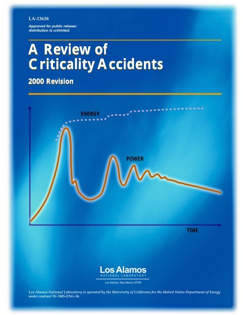
Cover Illustration: Power and energy traces representative <strong>of</strong> a typical criticality excursion in<br />
solution - from the SILENE experimental report, reference # 4.<br />
An Affirmative Action/Equal Opportunity Employer<br />
This report was prepared as an account <strong>of</strong> work sponsored by an agency <strong>of</strong> the United States Government. Neither The Regents <strong>of</strong> the University <strong>of</strong><br />
California, the United States Government nor any agency there<strong>of</strong>, nor any <strong>of</strong> their employees, makes any warranty, express or implied, or assumes any<br />
legal liability or responsibility for the accuracy, completeness, or usefulness <strong>of</strong> any information, apparatus, product, or process disclosed, or represents<br />
that its use would not infringe privately owned rights. Reference herein to any specific commercial product, process, or service by trade name,<br />
trademark, manufacturer, or otherwise, does not necessarily constitute or imply its endorsement, recommendation, or favoring by The Regents <strong>of</strong> the<br />
University <strong>of</strong> California, the United States Government, or any agency there<strong>of</strong>. The views and opinions <strong>of</strong> authors expressed herein do not necessarily<br />
state or reflect those <strong>of</strong> The Regents <strong>of</strong> the University <strong>of</strong> California, the United States Government, or any agency there<strong>of</strong>.Los Alamos National<br />
Laboratory strongly supports academic freedom and a researcherÕs right to publish; as an institution, however, the Laboratory does not endorse the<br />
viewpoint <strong>of</strong> a publication or guarantee its technical correctness.
A <strong>Review</strong> <strong>of</strong><br />
<strong>Criticality</strong> <strong>Accidents</strong><br />
2000 Revision<br />
LA-13638<br />
Issued: May 2000<br />
United States Authors:<br />
Thomas P. McLaughlin<br />
Shean P. Monahan<br />
Norman L. Pruvost*<br />
Russian Federation Authors:<br />
Vladimir V. Frolov**<br />
Boris G. Ryazanov***<br />
Victor I. Sviridov †<br />
*Senior Analyst. Galaxy Computer Services, Inc., Santa Fe, NM 87501.<br />
**Lead Researcher. Institute <strong>of</strong> Physics and Power Engineering (IPPE),<br />
Obninsk, Russia 249020.<br />
***Head <strong>of</strong> the Nuclear Safety Division. Institute <strong>of</strong> Physics and Power<br />
Engineering (IPPE), Obninsk, Russia 249020.<br />
† Head <strong>of</strong> the Nuclear Safety Laboratory. Institute <strong>of</strong> Physics and Power<br />
Engineering (IPPE), Obninsk, Russia 249020.<br />
Los Alamos<br />
NATIONAL LABORATORY<br />
Los Alamos, New Mexico 87545
FOREWARD<br />
We, <strong>of</strong> the early decades at Pajarito Site, Los Alamos, were near a number <strong>of</strong> accidental<br />
bursts <strong>of</strong> radiation in the course <strong>of</strong> critical experiments. In the first <strong>of</strong> these, the person at the<br />
controls exclaimed “a disaster!” With a quarter-mile separation protecting operators, each <strong>of</strong><br />
these “disasters” proved to be without consequence. Nevertheless, errors that led to them should<br />
have been avoided, and accounts <strong>of</strong> these accidents were disseminated to discourage recurrence.<br />
A serious process criticality accident at Los Alamos was another matter, because protection<br />
<strong>of</strong> operators was supposed to have been provided by criticality safety practices instead <strong>of</strong> built-in<br />
features such as shielding or distance. In this case, publication brought out obscure causes that<br />
demanded consideration in the discipline <strong>of</strong> criticality safety.<br />
The value <strong>of</strong> publication <strong>of</strong> both types <strong>of</strong> accident led William R. Stratton <strong>of</strong> the Pajarito<br />
Group to bring together all available descriptions in his A <strong>Review</strong> <strong>of</strong> <strong>Criticality</strong> <strong>Accidents</strong>, the<br />
linchpin <strong>of</strong> this account.<br />
Hugh C. Paxton<br />
Los Alamos, NM<br />
August 1999<br />
v
PREFACE<br />
This document is the second revision <strong>of</strong> A <strong>Review</strong> <strong>of</strong> <strong>Criticality</strong> <strong>Accidents</strong>. The first was<br />
issued as report LA-3611 in 1967 and authored by William R. Stratton. 1 At that time, he was a<br />
staff member in the Critical Experiments Group at Los Alamos and a member <strong>of</strong> the Atomic<br />
Energy Commission’s Advisory Committee on Reactor Safeguards. The first revision was published<br />
with the same title in 1989 as document NCT-04. 2 This revision was carried out by<br />
David R. Smith, a colleague <strong>of</strong> Stratton’s in the Critical Experiments Group during the 60’s and<br />
70’s and the Laboratory’s <strong>Criticality</strong> Safety Officer. In 1980, the criticality safety function was<br />
removed from the Critical Experiments Group and made a separate entity in the Laboratory’s<br />
Health and Safety organization with Smith as the first group leader.<br />
With the advent <strong>of</strong> cooperative research and information exchanges between scientists in the<br />
Russian Federation (Russia, R.F.) <strong>of</strong> the Former Soviet Union and Los Alamos National Laboratory<br />
in the early 1990s, discussions began to investigate possible joint work in the field <strong>of</strong> nuclear<br />
criticality safety (to be referred to hereafter as simply “criticality safety”). By 1994, interactions<br />
were ongoing between Los Alamos and four Russian sites with criticality safety interests: the<br />
Institute <strong>of</strong> Physics and Power Engineering (IPPE) in Obninsk; the All Russian Scientific Research<br />
Institute <strong>of</strong> Experimental Physics (VNIIEF) in Sarov (formerly Arzamas-16); the All<br />
Russian Scientific Research Institute <strong>of</strong> Technical Physics (VNIITF) in Snezhinsk (formerly<br />
Chelyabinsk-70); and the Kurchatov Institute (KI) in Moscow.<br />
<strong>Criticality</strong> safety staff at IPPE have regulatory oversight responsibility for the four major<br />
fissile material production and handling sites where process facility criticality accidents have<br />
occurred. These are the Mayak Production Association (Mayak), the Siberian Chemical Combine<br />
(Tomsk-7) in Seversk, the Electrostal Machine Building Plant in Electrostal, and the Novosibirsk<br />
Chemical Concentrates Plant in Novosibirsk. Thus, criticality safety staff from these four sites<br />
were directly involved in the 13 Russian process accidents described herein. The other three<br />
institutes, Arzamas-16, Chelyabinsk-70, and the Kurchatov Institute have critical experiment and<br />
reactor development capabilities; accidents in this category have occurred at these sites.<br />
This report, planned to be published in both English and Russian language versions, is the<br />
fruit <strong>of</strong> cooperative efforts <strong>of</strong> criticality safety specialists in both countries. It not only includes<br />
all <strong>of</strong> the Russian criticality accidents, but also revises the US and UK process facility accidents<br />
reported in the second edition. The revisions to the US and UK process accident descriptions are<br />
mainly expansions <strong>of</strong> the text to include information that was previously only in reference documents.<br />
In a few instances, technical corrections were necessary. The expanded descriptions are<br />
provided for the benefit <strong>of</strong> the broader audience that this document has been attracting over the<br />
years.<br />
Finally, as this report was almost to be printed in September 1999, a criticality accident<br />
occurred at the JCO fuel processing facility in Japan. Printing was delayed until this most recent<br />
accident could be fully understood and documented herein. It is the goal <strong>of</strong> the authors that with<br />
this expanded report, the causes <strong>of</strong> criticality accidents and their consequences will be better<br />
understood and the safety and efficiency <strong>of</strong> operations with significant quantities <strong>of</strong> fissile materials<br />
will be enhanced.<br />
vii
ACKNOWLEDGMENTS<br />
Many people have contributed significantly to the completion <strong>of</strong> this second revision <strong>of</strong><br />
A <strong>Review</strong> <strong>of</strong> <strong>Criticality</strong> <strong>Accidents</strong>. The relative importance <strong>of</strong> the contribution <strong>of</strong> each person is<br />
not intended by the ordering <strong>of</strong> names. Each person made a necessary contribution to the final<br />
document.<br />
For the Russian accident information:<br />
Gennadiy T. Kirillov—Tomsk-7<br />
Mikhail I. Kuvshinov—Arzamas-16<br />
Dimitri M. Parfanovich—Kurchatov Institute<br />
Aleksandr V. Romanov—Electrostal<br />
Igor G. Smirnov—Arzamas-16<br />
Gennadiy S. Starodubtsev—Mayak<br />
A. P. Suslov—Mayak<br />
Vladimir Teryokhin—Chelyabinsk-70<br />
Aleksandr G. Ustyugov—Novosibirsk<br />
Sergei Vorontsov—Arzamas-16<br />
Isao Takeshita—Japanese Atomic Energy Research Institute<br />
The U.S. authors are indebted to each <strong>of</strong> the above for answering innumerable questions,<br />
<strong>of</strong>ten by telephone, at home, late at night in Russia in order to accommodate a mid-morning<br />
meeting time in Los Alamos. In particular, we acknowledge that Igor G. Smirnov, Sergei<br />
Vorontsov, Mikhail I. Kuvshinov, and Vladimir Teryokhin endured about three hours <strong>of</strong> “interrogation”<br />
one night at one <strong>of</strong> the Los Alamos authors’ homes, and were recompensed only with a<br />
meal. On another occasion, after a similar evening <strong>of</strong> questions and discussion, Gennadiy<br />
Starodubtsev agreed to return two evenings later for another four-hour session, each time accepting<br />
only a meal as payment. These evening sessions took place after a full day <strong>of</strong> other business<br />
in Los Alamos. Gennadiy Starodubtsev was motivated by a personal desire to contribute to an<br />
accurate, complete recounting <strong>of</strong> the seven Mayak accidents.<br />
Barbara D. Henderson played a key administrative role in keeping the project on track in<br />
many regards. She has been involved with the project from the time it was only an ill-defined<br />
goal to the final product, a nearly eight-year span.<br />
Charles T. Rombough assisted with this project for more than two years. He has provided<br />
seamless transmission <strong>of</strong> information, text, figures, and photographs, in both English and Russian<br />
languages, in addition to producing electronic files <strong>of</strong> all intermediate drafts.<br />
Nellie Schachowskoj Shropshire and Olga Viddo provided both interpretation and translation<br />
services for the many meetings, telephone calls, emails, and intermediate drafts.<br />
Hugh C. Paxton once again, at the young age <strong>of</strong> 91 years, provided insightful and thoughtprovoking<br />
comments on the technical content. He also contributed sharp editorial comments.<br />
David R. Smith provided valuable comments on various drafts, particularly on lessons<br />
learned from the accidents.<br />
William R. Stratton provided valuable comments on early drafts <strong>of</strong> the report.<br />
ix
Tom Jones was invaluable in generating most <strong>of</strong> the schematics found in Part I and in<br />
Appendix B, under significant time constraints.<br />
Jerry McKamy <strong>of</strong> the Department <strong>of</strong> Energy and Chuck Nilsen <strong>of</strong> the Nuclear Regulatory<br />
Commission were instrumental in recognizing the value <strong>of</strong> and providing financial support for<br />
this project. They both also exhibited a vanishing talent by not micromanaging the project, for<br />
which the authors are grateful.<br />
x
CONTENTS<br />
FOREWORD .................................................................................................................................. v<br />
PREFACE ..................................................................................................................................... vii<br />
ACKNOWLEDGMENTS ............................................................................................................. ix<br />
TABLE OF CONTENTS...............................................................................................................xi<br />
LIST OF FIGURES ...................................................................................................................... xv<br />
LIST OF TABLES ....................................................................................................................... xix<br />
ABSTRACT ................................................................................................................................... 1<br />
INTRODUCTION .......................................................................................................................... 1<br />
I. PROCESS ACCIDENTS........................................................................................................... 2<br />
A. ACCIDENT DESCRIPTIONS ............................................................................................ 2<br />
1. Mayak Production Association, 15 March 1953 ........................................................... 7<br />
2. Mayak Production Association, 21 April 1957 ............................................................. 9<br />
3. Mayak Production Association, 2 January 1958 ......................................................... 11<br />
4. Oak Ridge Y-12 Plant, 16 June 1958........................................................................... 13<br />
5. Los Alamos Scientific Laboratory, 30 December 1958 ............................................... 16<br />
6. Idaho Chemical Processing Plant, 16 October 1959 ................................................... 18<br />
7. Mayak Production Association, 5 December 1960 ..................................................... 19<br />
8. Idaho Chemical Processing Plant, 25 January 1961 .................................................... 22<br />
9. Siberian Chemical Combine, 14 July 1961 ................................................................. 23<br />
10. Hanford Works, 7 April 1962 ...................................................................................... 27<br />
11. Mayak Production Association, 7 September 1962 ..................................................... 28<br />
12. Siberian Chemical Combine, 30 January 1963 ........................................................... 30<br />
13. Siberian Chemical Combine, 2 December 1963 ......................................................... 31<br />
14. United Nuclear Fuels Recovery Plant, 24 July 1964 ................................................... 33<br />
15. Electrostal Machine Building Plant, 3 November 1965 .............................................. 35<br />
16. Mayak Production Association, 16 December 1965 ................................................... 37<br />
17. Mayak Production Association, 10 December 1968 ................................................... 40<br />
18. Windscale Works, 24 August 1970 .............................................................................. 43<br />
19. Idaho Chemical Processing Plant, 17 October 1978 ................................................... 45<br />
20. Siberian Chemical Combine, 13 December 1978 ....................................................... 47<br />
21. Novosibirsk Chemical Concentration Plant, 15 May 1997 ......................................... 50<br />
22. JCO Fuel Fabrication Plant, 30 September 1999 ........................................................ 53<br />
B. PHYSICAL AND NEUTRONIC CHARACTERISTICS FOR THE PROCESS<br />
FACILITY CRITICALITY ACCIDENTS ........................................................................ 57<br />
Accident Reconstruction.................................................................................................... 57<br />
Geometry ........................................................................................................................... 57<br />
Material.............................................................................................................................. 59<br />
Discussion.......................................................................................................................... 59<br />
Conclusions ....................................................................................................................... 60<br />
Fission Yields ..................................................................................................................... 61<br />
xi
C. OBSERVATIONS AND LESSONS LEARNED FROM PROCESS CRITICALITY<br />
ACCIDENTS .................................................................................................................... 64<br />
Observations ..................................................................................................................... 64<br />
Lessons Learned ............................................................................................................... 65<br />
Lessons <strong>of</strong> Operational Importance .................................................................................. 65<br />
Lessons <strong>of</strong> Supervisory, Managerial, and Regulatory Importance ................................... 66<br />
Conclusions ...................................................................................................................... 67<br />
II. REACTOR AND CRITICAL EXPERIMENT ACCIDENTS ................................................ 68<br />
A. FISSILE SOLUTION SYSTEMS .................................................................................... 70<br />
1. Los Alamos Scientific Laboratory, December 1949 ................................................... 70<br />
2. Hanford Works, 16 November 1951 ........................................................................... 70<br />
3. Oak Ridge National Laboratory, 26 May 1954 .......................................................... 71<br />
4. Oak Ridge National Laboratory, 1 February 1956 ..................................................... 72<br />
5. Oak Ridge National Laboratory, 30 January 1968 ..................................................... 73<br />
B. BARE AND REFLECTED METAL ASSEMBLIES ....................................................... 74<br />
1. Los Alamos Scientific Laboratory, 21 August 1945.................................................. 74<br />
2. Los Alamos Scientific Laboratory, 21 May 1946 ....................................................... 74<br />
3. Los Alamos Scientific Laboratory, 1 February 1951 .................................................. 77<br />
4. Los Alamos Scientific Laboratory, 18 April 1952 ...................................................... 78<br />
5. Sarov (Arzamas-16), 9 April 1953 ............................................................................. 78<br />
6. Los Alamos Scientific Laboratory, 3 February 1954 .................................................. 80<br />
7. Los Alamos Scientific Laboratory, 12 February 1957 ................................................ 80<br />
8. Los Alamos Scientific Laboratory, 17 June 1960 ....................................................... 83<br />
9. Oak Ridge National Laboratory, 10 November 1961 ................................................. 84<br />
10. Sarov (Arzamas-16), 11 March 1963 ......................................................................... 84<br />
11. Lawrence Livermore Laboratory, 26 March 1963 ...................................................... 86<br />
12. White Sands Missile Range, 28 May 1965................................................................. 86<br />
13. Chelyabinsk-70, 5 April 1968 ..................................................................................... 87<br />
14. Aberdeen Proving Ground, 6 September 1968 ........................................................... 89<br />
15. Sarov (Arzamas-16), 17 June 1997 ............................................................................ 89<br />
C. MODERATED METAL OR OXIDE SYSTEMS ............................................................ 93<br />
xii<br />
1. Los Alamos Scientific Laboratory, 6 June 1945 ......................................................... 93<br />
2. Chalk River Laboratory, late 1940s or early 1950s .................................................... 94<br />
3. Argonne National Laboratory, 2 June 1952 ................................................................ 94<br />
4. Chalk River Laboratory, Atomic Energy <strong>of</strong> Canada, Ltd., 12 December 1952 .......... 95<br />
5. National Reactor Testing Station, 22 July 1954 ......................................................... 95<br />
6. Boris Kidrich Institute, 15 October 1958 ................................................................... 96<br />
7. Centre dÉtudes Nucleaires de Saclay, France, 15 March 1960 .................................. 97<br />
8. National Reactor Testing Station, 3 January 1961...................................................... 97<br />
9. National Reactor Testing Station, 5 November 1962 ................................................. 98<br />
10. Mol, Belgium, 30 December 1965 ............................................................................. 98<br />
11. Kurchatov Institute, 15 February 1971 ....................................................................... 99<br />
12. Kurchatov Institute, 26 May 1971 ............................................................................ 101<br />
13. The RA-2 Facility, 23 September 1983 .................................................................... 103
D. MISCELLANEOUS SYSTEMS .................................................................................... 104<br />
1. Los Alamos Scientific Laboratory, 11 February 1945 .............................................. 104<br />
2. National Reactor Testing Station, 29 November 1955 ............................................. 104<br />
3. Los Alamos Scientific Laboratory, 3 July 1956........................................................ 105<br />
4. National Reactor Testing Station, 18 November 1958 ............................................. 106<br />
5. Los Alamos Scientific Laboratory, 11 December 1962 ............................................ 106<br />
III. POWER EXCURSIONS AND QUENCHING MECHANISMS ........................................ 107<br />
REFERENCES ........................................................................................................................... 111<br />
APPENDIX A: GLOSSARY OF NUCLEAR CRITICALITY TERMS ................................... 116<br />
APPENDIX B: EQUIPMENT DIAGRAMS AND TABULAR PHYSICAL AND<br />
YIELD DATA FOR THE 22 PROCESS ACCIDENTS ................................... 120<br />
xiii
FIGURES<br />
1. Chronology <strong>of</strong> process criticality accidents........................................................................ 2<br />
2. Map <strong>of</strong> the Russian Federation showing the sites <strong>of</strong> the process criticality accidents,<br />
the capital, Moscow, and Obinisk, the location <strong>of</strong> the regulating authority, IPPE ............. 3<br />
3. Map <strong>of</strong> the United States showing the sites <strong>of</strong> the process criticality accidents, and the<br />
capital, Washington.............................................................................................................4<br />
4. Map <strong>of</strong> the United Kingdom showing the site <strong>of</strong> the process criticality accident and<br />
the capital, London .............................................................................................................5<br />
5. Map <strong>of</strong> Japan showing the site <strong>of</strong> the process criticality accident and the<br />
capital, Tokyo...................................................................................................................... 6<br />
6. Layout <strong>of</strong> vessels and equipment in the staging area ......................................................... 7<br />
7. Equipment layout for the oxalate precipitation and filtration process.............................. 10<br />
8. Layout <strong>of</strong> the experimental equipment ............................................................................. 12<br />
9. Simplified diagram <strong>of</strong> the C-1 wing vessels and interconnecting piping involved in<br />
the accident. ...................................................................................................................... 14<br />
10. Drum in which the 1958 Y-12 process criticality accident occurred................................ 15<br />
11. Configuration <strong>of</strong> solutions (aqueous and organic) in the vessel before the accident ....... 16<br />
12. Vessel in which the 1958 Los Alamos process criticality accident occurred ................... 17<br />
13. Layout <strong>of</strong> vessels in Glovebox 10 and the holding vessel external to the glovebox ........ 19<br />
14. Layout <strong>of</strong> DSS–6 ..............................................................................................................23<br />
15. Vacuum pump diagram showing oil reservoir (Dimensions are in mm) .......................... 24<br />
16. Oil reservoir (Dimensions are in mm) .............................................................................. 25<br />
17. Layout <strong>of</strong> glovebox equipment ......................................................................................... 29<br />
18. Process vessels and material flow diagram. ..................................................................... 30<br />
19. Schematic <strong>of</strong> vessels showing organic and aqueous solutions (not intended to imply<br />
the exact conditions at the time <strong>of</strong> the accident) .............................................................. 32<br />
20. Layout <strong>of</strong> UF to uranium oxide conversion equipment and associated<br />
6<br />
vacuum system ................................................................................................................. 35<br />
21. Residue recovery area layout ............................................................................................ 37<br />
22. Layout <strong>of</strong> dissolution glovebox ........................................................................................ 38<br />
23. Plan view <strong>of</strong> the tanks involved in the accident ................................................................ 41<br />
24. Elevation view <strong>of</strong> the tanks involved in the accident........................................................ 41<br />
25. Process equipment related to the criticality accident........................................................ 43<br />
26. Solution transfer as reconstructed from the transparent plastic mockup <strong>of</strong> the transfer<br />
vessel. Configuration (B) is the postulated state at the time <strong>of</strong> the accident .................... 44<br />
xv
27. First cycle extraction line equipment. The accident occurred in the lower<br />
disengagement section <strong>of</strong> the H-100 column ................................................................... 45<br />
28. Storage container .............................................................................................................. 47<br />
29. A simplified layout <strong>of</strong> Glovebox 13 ................................................................................. 47<br />
30. Intended sequence for the transfer <strong>of</strong> ingots from and to Glovebox 13 ........................... 48<br />
31. Actual order <strong>of</strong> ingot transfers from and to Glovebox 13. The solid lines represent<br />
the actions <strong>of</strong> operator A and the dotted lines the actions <strong>of</strong> operator B .......................... 49<br />
32. Major components <strong>of</strong> the chemical-etching process ........................................................ 50<br />
33. Sequence <strong>of</strong> alarms and duration that the radiation levels exceeded the alarm<br />
level (36 mR/h) ................................................................................................................. 52<br />
34. Authorized and executed procedures ................................................................................ 54<br />
35. The precipitation vessel in which the process criticality accident occurred..................... 55<br />
36. The ratio <strong>of</strong> cylindrical to spherical critical masses <strong>of</strong> U(93)O F solutions, unreflected<br />
2 2<br />
and with water reflector, as a function <strong>of</strong> cylinder height to cylinder diameter ratio ....... 59<br />
37. Critical masses <strong>of</strong> homogeneous water moderated U(93.2) spheres. Solution data<br />
appear unless indicated otherwise. The accidents are shown by numbered circles.......... 60<br />
38. Critical masses <strong>of</strong> water-reflected spheres <strong>of</strong> hydrogen-moderated U(93), U(30.3),<br />
U(5.00), U(3.00), and U(2.00). The accidents are shown by numbered circles ............... 61<br />
39. Critcial masses <strong>of</strong> homogeneous water moderated plutonium spheres. The points<br />
suggesting an intermediate curve apply to water reflected Pu(No ) solution with<br />
3 4<br />
1 N HNO and 3.1% 3 240Pu content. The accidents are shown by numbered circles ......... 62<br />
40. The Oak Ridge National Laboratory uranium solution assembly showing the normal<br />
and detached positions <strong>of</strong> the central poison rod.............................................................. 71<br />
41. Plutonium sphere partially reflected by tungsten-carbide blocks..................................... 74<br />
42. Configuration <strong>of</strong> beryllium reflector shells prior to the accident 21 May 1946 ............... 75<br />
43. Calculated fission rate for the 6.2-kg plutonium sphere ................................................... 76<br />
44. Calculated total fissions vs. time for the 6.2-kg plutonium sphere .................................. 76<br />
45. The Los Alamos Scientific Laboratory aquarium assembly machine employed for<br />
measurements <strong>of</strong> critical separation distances .................................................................. 77<br />
46. FKBN and assembly involved in the 9 April 1953 accident ............................................ 78<br />
47. Building B floor plan ........................................................................................................79<br />
48. The Los Alamos Scientific Laboratory Lady Godiva assembly (unreflected<br />
enriched-uranium sphere) in the scrammed configuration ............................................... 81<br />
49. Lady Godiva after the excursion <strong>of</strong> 3 February 1954 ....................................................... 82<br />
50. Burst rod and several sections <strong>of</strong> Lady Godiva showing oxidation and warpage that<br />
accompanied the second accident, 12 February 1957 ...................................................... 83<br />
xvi
51. MSKS and assembly involved in the 11 March 1963 accident ........................................ 84<br />
52. Building B floor plan ........................................................................................................85<br />
53. Approximate accident configuration <strong>of</strong> the FKBN vertical lift assembly machine<br />
and core............................................................................................................................. 87<br />
54. FKBN-2M building layout ............................................................................................... 90<br />
55. FKBN-2M experimental layout ........................................................................................ 90<br />
56. Accident configuration ..................................................................................................... 91<br />
57. Calculated power history for the accident ........................................................................ 92<br />
58. Removal <strong>of</strong> the main core <strong>of</strong> the assembly from the lower copper hemishell reflector ... 92<br />
59. The destructive excursion in BORAX, 22 July 1954 ....................................................... 96<br />
60. Photograph <strong>of</strong> the SF-7 control and experimental rooms where the first<br />
accident occurred ............................................................................................................ 100<br />
61. Mockup <strong>of</strong> the accident configuration for the 26 May 1971 accident............................ 102<br />
62. The LASL Honeycomb assembly machine. The movable section (right) is in the<br />
withdrawn position and the aluminum matrix is only partially loaded .......................... 105<br />
63. Energy model computation <strong>of</strong> power and energy release vs time. The initial reactivity<br />
is 1.2 $ above delayed critical. Neutron lifetime values are 10-8 , 10-6 , and 10-4 seconds.<br />
The bottom panel shows the corresponding curves <strong>of</strong> reactivity vs time ....................... 108<br />
64. Energy model computation <strong>of</strong> power vs time. The initial reactivity is 1.0 $ above<br />
delayed critical. Neutron lifetime values are 10 -8 , 10 -6 , and 10 -4 seconds. The bottom<br />
panel shows the corresponding curves <strong>of</strong> reactivity vs time .......................................... 109<br />
xvii
TABLES<br />
1. Contents <strong>of</strong> Vessels 1 through 7 as Recorded in the Operational Log Before<br />
the Accident ........................................................................................................................ 8<br />
2. The Expected Contents <strong>of</strong> Vessel 18 after the Planned Transfer ........................................ 8<br />
3. The Actual Contents <strong>of</strong> Vessel 18 at the Time <strong>of</strong> the Accident. ......................................... 8<br />
4. The Seven Vessels Related to the Reconstruction <strong>of</strong> the <strong>Criticality</strong> Accident .................. 20<br />
5. Chronology <strong>of</strong> Batch Composition Leading to Overloading <strong>of</strong> Vessel R0 in<br />
Glovebox 9........................................................................................................................ 21<br />
6. Analysis <strong>of</strong> Accident Solution Recovered from Holding Vessel and R3 .......................... 21<br />
7. Results <strong>of</strong> γ-Radiation Exposure Rate Measurements at Oil Reservoir ........................... 26<br />
8. Characteristics <strong>of</strong> the First Three Excursions ................................................................... 52<br />
9. Reconstruction <strong>of</strong> Accident Geometry and Material Configurations ............................... 58<br />
10. Accident Fission Energy Releases .................................................................................... 63<br />
11. Reactor and Critical Experiment <strong>Accidents</strong>...................................................................... 68<br />
12. Pitch Versus Critical Number <strong>of</strong> Rods ............................................................................ 101<br />
xix
A REVIEW OF CRITICALITY ACCIDENTS<br />
ABSTRACT<br />
<strong>Criticality</strong> accidents and the characteristics <strong>of</strong> prompt power excursions are discussed. Sixty<br />
accidental power excursions are reviewed. Sufficient detail is provided to enable the reader to<br />
understand the physical situation, the chemistry and material flow, and when available the administrative<br />
setting leading up to the time <strong>of</strong> the accident. Information on the power history, energy<br />
release, consequences, and causes are also included when available. For those accidents that<br />
occurred in process plants, two new sections have been included in this revision. The first is an<br />
analysis and summary <strong>of</strong> the physical and neutronic features <strong>of</strong> the chain reacting systems. The<br />
second is a compilation <strong>of</strong> observations and lessons learned. Excursions associated with large<br />
power reactors are not included in this report.<br />
INTRODUCTION<br />
This revision <strong>of</strong> A <strong>Review</strong> <strong>of</strong> <strong>Criticality</strong> <strong>Accidents</strong>1,2 represents a significant expansion <strong>of</strong> the prior edition<br />
with the inclusion <strong>of</strong> one Japanese and 19 Russian<br />
accidents. In the first two parts <strong>of</strong> this report, 60<br />
criticality accidents are described. These are divided<br />
into two categories, those that occurred in process<br />
facilities (22), and thus were unexpected, and those that<br />
occurred during critical experiments or operations with<br />
research reactors (38).<br />
These two categories are based on the following<br />
considerations. Process facilities carrying out operations<br />
with fissile material avoid criticality accidents through<br />
physical and administrative controls. These controls are<br />
intended to prevent critical or near–critical configurations<br />
from ever occurring in the facility. Operating<br />
personnel are usually not technical experts in criticality<br />
physics. Under normal working conditions, however,<br />
operating personnel can be close to (arm’s length from)<br />
potentially critical configurations. In contrast, reactor<br />
and critical experiment research facilities purposefully<br />
plan and achieve near–critical and critical configurations.<br />
These operating personnel are usually experts in<br />
criticality physics. Although they carry out hands–on<br />
operations with fissile material under restrictions similar<br />
to those found in process facilities, the planned near–<br />
critical and critical configurations are performed under<br />
shielded or remote conditions.<br />
In most cases, the descriptions <strong>of</strong> the Russian<br />
accidents are somewhat lengthier than those that<br />
occurred in other countries. This is attributable to the<br />
lack <strong>of</strong> generally available references for the Russian<br />
accidents. In other words, the descriptive information in<br />
this report is all that is effectively available for these<br />
accidents. It has been gleaned from both the original<br />
Russian notes and discussions with those who had<br />
personal knowledge <strong>of</strong> the accidents. With the exception<br />
<strong>of</strong> the addition <strong>of</strong> the six Russian critical experiment<br />
accidents, Part II <strong>of</strong> this report is basically unchanged<br />
from that <strong>of</strong> the second edition.<br />
Although this edition is planned to be available in<br />
both English and Russian language versions, decisions<br />
had to be made concerning units and terminology,<br />
particularly in the English language version. We have<br />
attempted to conform to common international usage.<br />
However, units as originally reported are sometimes<br />
retained for historical accuracy. Also, we have chosen<br />
generally understood terminology and avoided terms<br />
that might be facility or industry specific. For example,<br />
the word “vessel” is used to describe most solution<br />
holding containers. Thus “filter vessel” is used instead<br />
<strong>of</strong> “filter boat,” a common U.S. chemical industry<br />
term.<br />
In Part III, a brief discussion <strong>of</strong> analytical methods<br />
and quenching mechanisms for power excursions is<br />
reproduced from the first revision. Two appendices are<br />
also new to this revision. Appendix A is a reproduction<br />
<strong>of</strong> LA-11627-MS, Glossary <strong>of</strong> Nuclear <strong>Criticality</strong><br />
Terms 3 (supplemented with one additional definition)<br />
to assist the reader. In Appendix B diagrams <strong>of</strong> each <strong>of</strong><br />
the 22 process vessels in which the accidents took<br />
place are shown along with tabular summaries <strong>of</strong> the<br />
system parameters (mass, volume, etc.).<br />
The emphasis <strong>of</strong> this revision has been threefold.<br />
First, it was to include the one Japanese and 19<br />
Russian accidents. Fourteen <strong>of</strong> these took place in<br />
process facilities and six happened during critical<br />
experiments and research reactor operations. A second<br />
focus <strong>of</strong> this effort has been to thoroughly review the<br />
eight process facility accidents described in the prior<br />
revision <strong>of</strong> this document and their supporting<br />
references. This led to some technical corrections and<br />
modest expansions <strong>of</strong> the process descriptions for the<br />
benefit <strong>of</strong> the expanded audience that this report has<br />
attracted over the years. Third, two analyses <strong>of</strong> the 22<br />
process accidents are included. These are (1) physical<br />
and neutronic characteristics with an emphasis on<br />
understanding systematic features and (2) observations<br />
and lessons learned from these accidents.<br />
1
The 22 criticality accidents that occurred during<br />
process operations are each described in one to several<br />
pages, accompanied by schematics and photographs<br />
when available. These are the accidents that are<br />
directly relevant to process criticality safety. In all<br />
cases the level <strong>of</strong> detail is sufficient to understand the<br />
physical conditions. The neutronic, physical, radiological,<br />
and human consequences <strong>of</strong> the accidents are<br />
presented. Causes are included for those accidents for<br />
which this information was reported in the original<br />
documentation or was available from those with first<br />
hand knowledge.<br />
As supplements to the descriptions, two new<br />
sections have been added to Part I <strong>of</strong> this revision. The<br />
first new section presents the results <strong>of</strong> simplified re–<br />
constructions <strong>of</strong> the physical and neutronic aspects <strong>of</strong><br />
each accident. These re–constructions are compared to<br />
known conditions for criticality. In addition, the energy<br />
releases, both the first spike and the total excursion<br />
yield, are discussed with respect to expected values<br />
based on data from the SILENE, CRAC, and KEWB<br />
experiments. 4,5,6 Complementing this section is<br />
Appendix B that contains diagrams <strong>of</strong> the vessels in<br />
which the 22 accidents occurred and tables showing<br />
the parameters (fissile mass, volume, etc.) <strong>of</strong> the<br />
simplified re–constructions.<br />
In the second new section, observations and lessons<br />
learned, extracted from a thorough review <strong>of</strong> all <strong>of</strong> the<br />
accidents, are presented. This process was necessarily<br />
subjective since in many cases there were obvious<br />
2<br />
I. PROCESS ACCIDENTS<br />
Figure 1. Chronology <strong>of</strong> process criticality accidents.<br />
operator actions that were directly related to the<br />
accident, but seldom were the operator’s thoughts<br />
reported. This summary <strong>of</strong> lessons learned should<br />
prove valuable as a training tool. It may also assist<br />
management by providing insight into major risk<br />
contributors thus helping to reduce risks and to prevent<br />
accidnts.<br />
A chronology <strong>of</strong> the accidents that occurred in<br />
process facilities is provided in Figure 1. Below are<br />
listed highlights <strong>of</strong> these 22 process accidents.<br />
• 21 occurred with the fissile material in solutions or<br />
slurries.<br />
• One occurred with metal ingots.<br />
• None occurred with powders.<br />
• 18 occurred in manned, unshielded facilities.<br />
• 9 fatalities resulted.<br />
• 3 survivors had limbs amputated.<br />
• No accidents occurred in transportation.<br />
• No accidents occurred while fissile material was<br />
being stored.<br />
• No equipment was damaged.<br />
• Only one accident resulted in measurable fission<br />
product contamination (slightly above natural levels)<br />
beyond the plant boundary.<br />
• Only one accident resulted in measurable exposures<br />
(well below allowable worker annual exposures) to<br />
members <strong>of</strong> the public.<br />
Russian Federation United States United Kingdom Japan<br />
45 50 55 60 65 70 75 80 85 90 95<br />
A. ACCIDENT DESCRIPTIONS<br />
The 22 accident descriptions are presented chronologically<br />
in this report without regard to country.<br />
Figures 2, 3, 4, and 5 are provided to orient the reader<br />
as to the accident locations in the Russian Federation,<br />
the United States, the United Kingdom, and Japan,<br />
respectively. The capital cities are also included, as<br />
well as Obninsk in Russia, where no accidents have<br />
occurred but where the Russian coeditors <strong>of</strong> this report<br />
work at the IPPE. The IPPE houses the regulatory<br />
body that oversees the four production sites (Mayak,<br />
Tomsk-7, Electrostal, and Novosibirsk), where the<br />
process accidents occurred.
3<br />
Black<br />
Sea<br />
Baltic Sea<br />
Obninsk<br />
Norwegian<br />
Sea<br />
Moscow<br />
Electrostal<br />
Mayak<br />
Tomsk<br />
Novosibirsk<br />
Sea <strong>of</strong><br />
Okhotsk<br />
Figure 2. Map <strong>of</strong> the Russian Federation showing the sites <strong>of</strong> the process criticality accidents, the capital, Moscow, and Obinisk, the location <strong>of</strong> the regulating<br />
authority, IPPE.<br />
Sea <strong>of</strong><br />
Japan<br />
Bering<br />
Sea
4<br />
Pacific<br />
Ocean<br />
Hanford<br />
Idaho Falls<br />
Los Alamos<br />
Oak Ridge<br />
Gulf <strong>of</strong><br />
Mexico<br />
Washington<br />
Wood River Junction<br />
Figure 3. Map <strong>of</strong> the United States showing the sites <strong>of</strong> the process criticality accidents, and the capital, Washington.<br />
Atlantic<br />
Ocean
North<br />
Atlantic<br />
Ocean<br />
Irish<br />
Sea<br />
Windscale<br />
London<br />
Figure 4. Map <strong>of</strong> the United Kingdom showing the site <strong>of</strong> the process criticality accident and the capital, London.<br />
North<br />
Sea<br />
English<br />
Channel<br />
5
6<br />
Sea <strong>of</strong><br />
Japan<br />
Philippine Sea<br />
Tokai–mura<br />
Tokyo<br />
Figure 5. Map <strong>of</strong> Japan showing the site <strong>of</strong> the process criticality accident and the capital, Tokyo.<br />
North<br />
Pacific<br />
Ocean
1. Mayak Production Association, 15 March 1953<br />
Plutonium nitrate solution in an interim storage vessel; single excursion; one serious exposure, one significant<br />
exposure.<br />
The accident occurred in a plutonium processing<br />
building. The plutonium had been recovered from<br />
irradiated uranium rods. After separation from the fuel<br />
rods, the plutonium in the form <strong>of</strong> nitrate solution, was<br />
put through several purification steps. Operations were<br />
performed on 6 hour shifts, 4 shifts per day. The<br />
building was not equipped with a criticality alarm<br />
system.<br />
Following purification, the plutonium nitrate<br />
solution was routed through a staging area before<br />
being sent on for further processing. Operations<br />
performed within the staging area included mixing,<br />
dilution, volume measurement, sampling for plutonium<br />
concentration and purity, and interim storage. Plutonium<br />
solution that failed purity requirements was<br />
returned for further purification. The staging area<br />
consisted <strong>of</strong> a concrete cell and adjacent space located<br />
in the corridor outside <strong>of</strong> the cell. Figure 6 shows the<br />
layout <strong>of</strong> the concrete cell and corridor.<br />
The staging area contained 15 identical short right<br />
circular cylindrical stainless steel vessels, each with a<br />
unique identification number. The vessels were<br />
400 mm in diameter and 320 mm high with the<br />
cylindrical axis oriented vertically. The staging area<br />
was not equipped with radiation monitoring instruments.<br />
<strong>Criticality</strong> control was implemented by a<br />
500 gram plutonium mass limit per vessel. <strong>Criticality</strong><br />
Cast Iron<br />
1 2 3 4 5 6 7<br />
Cell<br />
Concrete<br />
safety support consisted <strong>of</strong> part time effort by a staff<br />
physicist. Operators were not trained in criticality<br />
safety.<br />
The 15 vessels were separated into 2 linear arrays.<br />
The first array containing 7 evenly spaced vessels was<br />
located near the back wall <strong>of</strong> the concrete cell. This<br />
array was installed in May 1952 and was supplied with<br />
solutions through permanently installed transfer lines.<br />
The concrete cell was 3 m wide, 2 m deep, and 2.5 m<br />
high. Top surfaces <strong>of</strong> the vessels were less than 1 m<br />
above the cell floor. Located in front <strong>of</strong> the array was a<br />
vertical, 200 mm thick cast–iron plate. In addition, a<br />
125 mm thick cast–iron top plate was located horizontally<br />
above the 7 vessels. This plate had cutout holes<br />
above each vessel to allow access for making hose<br />
connections. Cadmium plates were positioned vertically<br />
between the 7 vessels. Procedures required that,<br />
for criticality safety purposes, vessels 2, 4, and 6 never<br />
contain solution. This constraint was expected to<br />
reduce neutronic interaction between the vessels.<br />
The second array containing 8 evenly spaced<br />
vessels was located in the corridor outside the concrete<br />
cell. This second array was installed after realization<br />
that the first array had inadequate capacity for the<br />
volume <strong>of</strong> plutonium solution being processed. Each<br />
vessel in the array was individually shielded by<br />
approximately 175 mm <strong>of</strong> cast–iron on 4 sides and<br />
Vacuum<br />
Trap<br />
Cast Iron<br />
Vacuum Pump<br />
Figure 6. Layout <strong>of</strong> vessels and equipment in the staging area.<br />
Corridor<br />
17 18 19 22 15 16 11 12<br />
7
with the concrete floor and wall on the remaining 2<br />
sides <strong>of</strong> the vessel. The criticality accident occurred in<br />
vessel 18.<br />
Staging operations involved solutions being<br />
transferred between vessels in an array and between<br />
arrays. Vacuum transfers between the two arrays were<br />
performed by manually connecting hoses up to 7 m in<br />
length. The vacuum system was located in a room<br />
adjacent to the concrete cell. To prevent plutonium<br />
solution from entering the vacuum system, a vacuum<br />
trap, located in the concrete cell, was used. This<br />
vacuum trap vessel was made <strong>of</strong> glass to allow for<br />
visual inspection.<br />
Procedures required that written instructions for<br />
each shift be reviewed by operating personnel at the<br />
beginning <strong>of</strong> the shift. A team <strong>of</strong> two or three people<br />
performed operations. Procedures also required that<br />
shift personnel review the results <strong>of</strong> solution sampling<br />
analysis.<br />
On Sunday, 15 March 1953, the written instructions<br />
alerted shift personnel that two transfers <strong>of</strong> plutonium<br />
solution were scheduled to arrive at the vessels in the<br />
concrete cell. Table 1 shows the contents <strong>of</strong> the seven<br />
vessels as recorded in the operational log before the<br />
accident. It should be noted that in violation <strong>of</strong><br />
procedures, vessels 2 and 4 were in use, and the 500<br />
gram mass limit was being ignored. A plan was<br />
prepared to receive the first transfer <strong>of</strong> plutonium<br />
solution. The plan specified that the contents <strong>of</strong><br />
vessels 2 and 4 were to be transferred to vessel 18,<br />
which was located in the second array. The operational<br />
log showed vessel 18 was empty. Based on the values<br />
in Table 1 and the assumption that vessel 18 was<br />
empty, this transfer would result in vessel 18 having<br />
the solution volume and plutonium mass given in<br />
Table 2.<br />
Two operators performed the transfer <strong>of</strong> solution<br />
from vessels 2 and 4 to vessel 18. One operator was<br />
positioned next to vessel 18 and the other was in the<br />
cell near vessels 2 and 4. Following completion <strong>of</strong> the<br />
transfers, the operator next to vessel 18 disconnected<br />
the hose. Immediately after disconnecting the hose, the<br />
operator noticed foaming and violent gas release from<br />
the vessel. With his hands the operator also observed<br />
that the vessel temperature was elevated well above<br />
room temperature. The operator in the cell noticed that<br />
solution had accumulated in the glass vacuum trap. The<br />
operator in the corridor immediately reconnected the<br />
transfer hose to vessel 18. Both operators then decided<br />
to transfer the contents <strong>of</strong> vessel 18 back to vessel 4.<br />
The loss to the vacuum trap during the excursion<br />
explains why criticality did not re–occur during this<br />
transfer. Water and nitric acid were then added to<br />
vessel 4 to dilute and cool the contents. The operators<br />
then split the contents <strong>of</strong> vessel 4 by transferring it to<br />
vessels 22 and 12 located in the corridor.<br />
8<br />
Table 1. Contents <strong>of</strong> Vessels 1 through 7 as<br />
Recorded in the Operational Log Before the<br />
Accident.<br />
Vessel<br />
Number<br />
Table 2. The Expected Contents <strong>of</strong> Vessel 18<br />
after the Planned Transfer.<br />
Vessel<br />
Number<br />
Table 3. The Actual Contents <strong>of</strong> Vessel 18 at the<br />
Time <strong>of</strong> the Accident.<br />
Vessel<br />
Number<br />
Solution<br />
Volume ( l)<br />
Solution<br />
Volume ( l)<br />
Solution<br />
Volume ( l)<br />
Pu Mass<br />
(g)<br />
Pu Mass<br />
(g)<br />
Pu Mass<br />
(g)<br />
Pu Conc.<br />
(g/ l)<br />
1 15.0 672.0 44.8<br />
2 10.0 58.0 5.8<br />
3 15.5 567.0 36.6<br />
4 16.0 566.0 35.4<br />
5 0.0 0.0 0.0<br />
6 0.0 0.0 0.0<br />
7 0.0 0.0 0.0<br />
Total 56.5 1863.0<br />
Pu Conc.<br />
(g/ l)<br />
18 26.0 624.0 23.8<br />
Neither <strong>of</strong> the two operators had any training in<br />
criticality safety and neither recognized that a criticality<br />
accident had occurred. They did not expect that<br />
there would be any health effects and they elected to<br />
not report their observations. They continued to<br />
perform the work <strong>of</strong> the shift by receiving 15.5 l <strong>of</strong><br />
solution containing 614 g <strong>of</strong> plutonium into vessel 5.<br />
Two days following the accident, 17 March 1953,<br />
the operator positioned near vessel 18 at the time <strong>of</strong> the<br />
accident abruptly became ill and requested medical<br />
assistance. An investigation was started after the<br />
operator reported his illness. The investigation determined<br />
that the operational log at the beginning <strong>of</strong> the<br />
shift on 15 March 1953 was in error (Table 1). The<br />
contents <strong>of</strong> vessel 1 at the beginning <strong>of</strong> the shift was<br />
actually 10 l <strong>of</strong> solution containing 448 g <strong>of</strong> plutonium,<br />
and not 15 l <strong>of</strong> solution with 672 g <strong>of</strong> plutonium.<br />
That is, vessel 1 contained 5 l less solution than<br />
was recorded in the operational log. The investigation<br />
also determined that the missing 5 l had been transferred<br />
into vessel 18 before the beginning <strong>of</strong> the shift.<br />
Table 3 shows the actual contents <strong>of</strong> vessel 18 at the<br />
Pu Conc.<br />
(g/ l)<br />
1 5.0 224.0 44.8<br />
2 10.0 58.0 5.8<br />
4 16.0 566.0 35.4<br />
Total 31.0 842.0 27.2
time <strong>of</strong> the accident. However, the investigation was<br />
not able to determine who made the transfer or when it<br />
had taken place.<br />
As part <strong>of</strong> the investigation, both experiments and<br />
calculations were performed to estimate the conditions<br />
for criticality in vessel 18. The results determined that<br />
30 l <strong>of</strong> solution containing 825 g <strong>of</strong> plutonium<br />
(27.5 g/ l) would be required for criticality. These<br />
values agree closely with the best estimate <strong>of</strong> the<br />
contents <strong>of</strong> vessel 18 at the time <strong>of</strong> the accident, 31 l<br />
<strong>of</strong> solution with 848 ± 45 g <strong>of</strong> plutonium (27.4 g/ l).<br />
One contributing cause <strong>of</strong> the accident was the<br />
unrecorded transfer <strong>of</strong> 5 l <strong>of</strong> solution from vessel 1 to<br />
vessel 18.<br />
The accidental excursion resulted in approximately<br />
2 × 10 17 fissions. This estimate was based on a<br />
temperature increase <strong>of</strong> 60°C in 31 l <strong>of</strong> solution. The<br />
2. Mayak Production Association, 21 April 1957<br />
This accident occurred in a large industrial building<br />
housing various operations with highly enriched<br />
uranium. Operations were being conducted under the 6<br />
hour shift, 4 shifts per day mode prevalent at Mayak.<br />
Rooms typically contained several gloveboxes separated<br />
from each other by about two meters and<br />
interconnected by various liquid transfer and vacuum<br />
lines. The accident took place in a filtrate receiving<br />
vessel that was part <strong>of</strong> batch mode, liquid waste<br />
processing and recovery operations.<br />
A layout <strong>of</strong> the glovebox and its equipment is<br />
shown in Figure 7. This was a typical one workstation<br />
deep by two workstations wide glovebox. The normal<br />
process flow was as follows: the main feed material,<br />
impure uranyl nitrate, was generated in upstream<br />
U(90) metal purification operations. This, along with<br />
oxalic acid, was introduced into the precipitation<br />
vessel, which was equipped with a stirrer and an<br />
external steam/water heating jacket. A batch would<br />
typically contain a few hundred grams <strong>of</strong> uranium feed<br />
in about 10 l <strong>of</strong> liquid; concentration was usually in<br />
the 30 to 100 g U/ l range. The stirrer operated<br />
continuously during the process to prevent the accumulation<br />
<strong>of</strong> oxalate precipitate on the vessel bottom.<br />
Precipitation <strong>of</strong> the uranyl oxalate trihydrate proceeded<br />
according to the following reaction:<br />
60°C temperature rise was based on the coarse<br />
observation that the solution following the accident<br />
was at or near the boiling temperature. The accident<br />
caused no physical damage to any equipment. The<br />
operator positioned in the cell received an estimated<br />
dose <strong>of</strong> 100 rad. The operator near vessel 18 received<br />
an estimated dose <strong>of</strong> 1,000 rad. He suffered severe<br />
radiation sickness and amputation <strong>of</strong> both legs. He died<br />
35 years after the accident.<br />
Procedures in place before the accident were<br />
unambiguous in specifying that vessels 2, 4, and 6<br />
were to never contain solution. The presence <strong>of</strong><br />
solution in vessels 2 and 4 at the beginning <strong>of</strong> the shift<br />
prior to the accident illustrates that procedures were<br />
being violated. The entries in Table 1 also shows that<br />
the mass limit <strong>of</strong> 500 g per vessel was being violated.<br />
Uranium precipitate, U(90), buildup in a filtrate receiving vessel; excursion history unknown; one fatality, five<br />
other significant exposures.<br />
( ) + + → • ↓<br />
UO2 NO3 H2C2O4 3H2OUO2C2O4 3H2O<br />
+2HNO<br />
2<br />
3<br />
The oxalate precipitate slurry was then vacuum<br />
transferred to a holding tank from which it was drained<br />
into a filter vessel. The precipitate containing the<br />
uranium was collected on the filter fabric, and the<br />
filtrate was pulled through by vacuum and collected in<br />
a filtrate receiving vessel, where the accident took<br />
place. This vessel was a horizontal cylinder 450 mm in<br />
diameter by 650 mm in length and had a volume <strong>of</strong><br />
approximately 100 l. As indicated in the figure, the<br />
filtrate was removed through a dip tube and transferred<br />
to an adjacent glovebox.<br />
A two tier hierarchy <strong>of</strong> procedures and requirements<br />
was in place at the time. Upper level documents<br />
described operations covering large work areas in<br />
general terms, while criticality guidance was contained<br />
in operating instructions and data sheets posted at each<br />
glovebox. Specifics associated with each batch, such as<br />
the fissile mass, time, temperature, and responsible<br />
operators, were recorded on the data sheets that were<br />
retained for one month. Important entries from the data<br />
sheets were transcribed to the main shift logs that were<br />
retained for one year.<br />
Operational and fissile mass throughput considerations<br />
dictated the design and layout <strong>of</strong> glovebox<br />
equipment. Thus, major pieces <strong>of</strong> equipment were not<br />
necessarily <strong>of</strong> favorable geometry. Limitation <strong>of</strong> the<br />
fissile mass per batch was the primary criticality<br />
control throughout the glovebox. The procedure called<br />
9
Precipitation<br />
Vessel<br />
Figure 7. Equipment layout for the oxalate precipitation<br />
and filtration process.<br />
for the U(90) mass per batch to be less than 800 g. The<br />
fissile mass was determined from the known volume<br />
and concentration <strong>of</strong> the uranyl nitrate. Historically this<br />
had resulted in relatively accurate fissile mass control.<br />
However, in spite <strong>of</strong> the fact that the operator followed<br />
the available procedures and did not violate criticality<br />
controls, there were several factors which contributed<br />
to the accumulation <strong>of</strong> uranium far in excess <strong>of</strong> that<br />
expected:<br />
• The temperature <strong>of</strong> the precipitating solution was an<br />
important process variable, but there was no monitoring<br />
device such as a thermocouple. Temperature<br />
rise was controlled by the heating time, routinely<br />
about 10 minutes; the solution was not brought to<br />
boiling. In addition to temperature, the stoichiometry<br />
<strong>of</strong> the solution was important, but control <strong>of</strong><br />
the uranium concentration was rather imprecise.<br />
Therefore the supernatant (the precipitate bearing<br />
liquid) that was fed to the filter vessel could have<br />
had an elevated temperature and/or acidity, resulting<br />
in a higher uranium concentration than anticipated.<br />
After the supernatant (now called the filtrate)<br />
entered the filtrate receiving vessel it would cool,<br />
resulting in additional precipitation <strong>of</strong> uranyl<br />
oxalate trihydrate and its slow accumulation into a<br />
hard, thin crust over much <strong>of</strong> the lower inside <strong>of</strong> the<br />
filtrate receiving vessel.<br />
• While not known for sure, it was suspected that<br />
minor defects in the filter fabric might also have<br />
contributed to an increased rate <strong>of</strong> precipitate accumulation<br />
in the filtrate vessel. Procedures called for<br />
the filter fabric to be replaced based on either visual<br />
evidence <strong>of</strong> defects or unusually high flow rates<br />
through the filter.<br />
10<br />
Stirrer<br />
Motor<br />
Glovebox Window<br />
Glove Ports<br />
Steam/Water<br />
Jacket<br />
Stirrer<br />
Holding<br />
Vessel<br />
Filter Vessel<br />
Filtrate Receiving Vessel<br />
• Operating instructions required a fissile mass accountability<br />
balance between the incoming and<br />
product fissile streams. If the difference was less<br />
than 5%, then the next batch could be introduced<br />
into the glovebox; but if the difference exceeded<br />
5%, then it was required that the vessels be cleaned<br />
out. Operating procedures required that these vessels<br />
be cleaned out on a specified schedule; however,<br />
there was apparently no limitation on the<br />
number <strong>of</strong> batches that could be processed between<br />
cleanings if the 5% threshold was not exceeded.<br />
Also, there was no tracking <strong>of</strong> the fissile mass as it<br />
accumulated between cleanings.<br />
• There was no on-line instrumentation for measuring<br />
process parameters such as uranium concentration<br />
or accumulation in the receiving vessel.<br />
• There was no operationally convenient way to<br />
visually inspect the inside <strong>of</strong> the receiving vessel.<br />
• Finally, a likely major contributor to the accident<br />
was a procedural change that had occurred two<br />
months before. In an attempt to minimize personnel<br />
contamination and process downtime associated<br />
with the previous practice <strong>of</strong> routine physical/mechanical<br />
cleaning <strong>of</strong> the vessels, it was decided that<br />
a simple acid flushing <strong>of</strong> the vessels would be adequate.<br />
Two months after the implementation <strong>of</strong> this<br />
procedural change, the accident occurred.<br />
While not a requirement for criticality control, the<br />
radiation control personnel routinely checked for<br />
uranium buildup with portable gamma–ray instruments<br />
from outside <strong>of</strong> the glovebox. They had not reported<br />
any increase in the normal background radiation field<br />
before the accident.<br />
The criticality accident occurred during what was<br />
thought to be routine vacuum filtration <strong>of</strong> a batch <strong>of</strong><br />
uranyl oxalate trihydrate precipitate slurry. Looking<br />
though the glovebox window, the operator observed the<br />
filter vessel fabric bulge upward, followed by a violent<br />
release <strong>of</strong> gas and ejection <strong>of</strong> some <strong>of</strong> the precipitate<br />
out <strong>of</strong> the filter vessel and onto the glovebox floor. The<br />
operator instinctively gathered up the precipitate by<br />
hand and put it back into the filter vessel. Immediately<br />
after (seconds, not minutes), the operator began to feel<br />
ill. The release <strong>of</strong> gas or vapor continued for about<br />
10 minutes, at which time sufficient solution had been<br />
ejected from the filtrate receiving vessel into the<br />
vacuum trap <strong>of</strong> an adjacent glovebox to cause the<br />
excursion to stop.<br />
There was no criticality alarm system or other<br />
means for alerting the operator or nearby personnel<br />
that a criticality accident had occurred. Furthermore,<br />
the operators had no criticality safety training. Originally,<br />
the circumstantial evidence <strong>of</strong> the gas release in<br />
the filter vessel and the sudden sickness <strong>of</strong> the operator<br />
were puzzling to the operational personnel in the room.<br />
The fact that a criticality accident had occurred was
determined by a radiation control person called to the<br />
scene. Measurements indicated that an intense gamma<br />
radiation field was emanating from the filtrate receiving<br />
vessel. These measurements were made about 15 to<br />
20 minutes after the accident. The radiation control<br />
person immediately ordered a prompt evacuation <strong>of</strong> the<br />
area.<br />
About 5.5 hours after the event, the exposure rate<br />
was measured to be 18 R/h at a distance <strong>of</strong> 1.5 m from<br />
the filtrate receiving vessel. It was estimated that this<br />
exposure rate corresponded to a fission yield <strong>of</strong><br />
approximately 1.0 × 10 17 fissions. Seventeen hours<br />
after the accident, measurement <strong>of</strong> the specific activity<br />
<strong>of</strong> the 24 Na in the operator’s blood showed<br />
245 Bq/cm 3 . Based on analysis done at that time, this<br />
activity was consistent with an absorbed whole body<br />
dose <strong>of</strong> about 3,000 rad. The operator died twelve days<br />
after the accident.<br />
Five other operators had been in the room at varying<br />
distances from the reacting vessel at the time <strong>of</strong> the<br />
accident. They received doses estimated to be upwards<br />
3. Mayak Production Association, 2 January 1958<br />
This particular accident was unique in that it<br />
occurred during operations with a vessel used for in–<br />
plant critical experiments. However, since the accident<br />
occurred well after the cessation <strong>of</strong> an experiment and<br />
during handling operations associated with transferring<br />
the fissile solution into favorable geometry bottles, it<br />
has been categorized as a process criticality accident.<br />
After the 21 April 1957 accident, it was decided to<br />
set up a small-scale experiment capability for measuring<br />
the critical parameters <strong>of</strong> high concentration,<br />
highly enriched uranyl nitrate solution. This was<br />
deemed necessary in light <strong>of</strong> the widespread use <strong>of</strong><br />
unfavorable geometry process vessels, the uncertainties<br />
in the critical parameters, and in recognition <strong>of</strong> two<br />
prior criticality accidents at the same plant. Previously,<br />
critical vessel dimensions and critical solution concentrations,<br />
masses, and volumes were estimated based on<br />
calculations, since directly applicable experimental<br />
results were unavailable in Russia at that time. The<br />
experimental capability was set up in the same building<br />
where large volumes <strong>of</strong> this material were being<br />
processed, giving efficient access to the fissile solution.<br />
The small critical experiment setup, shown in<br />
Figure 8, was located in a separate room in the main<br />
process building. It had only been in operation for two<br />
months at the time <strong>of</strong> the accident. During measurements,<br />
the critical experimenters worked at a control<br />
<strong>of</strong> 300 rad. All <strong>of</strong> them suffered from temporary<br />
radiation sickness but recovered without apparent<br />
long-term health effects.<br />
After dismantling the glovebox and cleaning the<br />
various pieces <strong>of</strong> equipment, a total <strong>of</strong> 3.06 kg <strong>of</strong> 235 U<br />
was discovered in the filtrate receiving vessel. This<br />
material was primarily in two forms: a thin, hard crust,<br />
due to long-term buildup, and a flocculent precipitate,<br />
the concentration <strong>of</strong> which decreased with height in the<br />
vessel. The accident caused no mechanical damage to<br />
this vessel, and the room was not contaminated. The<br />
glovebox was taken apart, cleaned, and reassembled<br />
with essentially the original equipment. The operation<br />
was resumed after just a few days. During the downtime,<br />
a radiation meter was installed on the glovebox,<br />
operating instructions were revised, and enhanced<br />
operator training was implemented.<br />
This accident led to the decision to set up an in–<br />
plant critical experiment measurement capability to<br />
better determine critical parameters for vessels in<br />
routine use. The next criticality accident at Mayak on<br />
2 January 1958 involved this critical experiment set up.<br />
Uranyl nitrate solution, U(90), in an experiment vessel; one prompt critical burst; three fatalities one serious<br />
exposure.<br />
panel located a few meters away from the setup and<br />
shielded by a 500 mm thick, water–filled slab tank<br />
located 600 mm from the experiment vessel. There<br />
were no criticality alarms installed in the building.<br />
This was the first day <strong>of</strong> work after the New Year’s<br />
holiday. While the plant generally ran continuously on<br />
four 6–hour shifts daily, there was only one team <strong>of</strong><br />
critical experimenters. They were working on their first<br />
shift <strong>of</strong> the new year, 13:00 to 19:00. Other plant<br />
operators were involved in preparing the fissile<br />
solution and in assembling the experimental apparatus,<br />
but the critical experiments were performed solely by<br />
this dedicated, knowledgeable team.<br />
The prior series <strong>of</strong> experiments had focused on<br />
determining critical parameters for smaller vessels and<br />
had been concluded before the end <strong>of</strong> the year. During<br />
the last working days <strong>of</strong> December the equipment for<br />
the next experimental series had been assembled. This<br />
was the first experiment conducted with this larger<br />
vessel. It was a cylindrical stainless steel vessel,<br />
750 mm inside diameter, with a wall thickness <strong>of</strong> 2 to<br />
4 mm, representative <strong>of</strong> the vessels in common use at<br />
the facility. The fissile solution, <strong>of</strong> known concentrations<br />
and volumes, was added from an overhead,<br />
graduated cylinder 3 l in capacity.<br />
The experiment vessel was bolted to a stand and sat<br />
atop an 8 mm thick steel support plate approximately<br />
11
0.8 m above the concrete floor and at least 1.5 m from<br />
any walls. Thus it was without appreciable reflection,<br />
approximating many in-plant situations. The vessel<br />
capacity was in excess <strong>of</strong> 400 l, permitting critical<br />
states to be measured over a wide range <strong>of</strong> conditions. A<br />
central guide tube accommodated a neutron source, and<br />
the leakage neutron flux was monitored with a<br />
BF 3 proportional counter located beneath the tank.<br />
Approach–to–critical measurements employed the<br />
standard inverse multiplication technique.<br />
After each experiment was completed, written<br />
procedures called for the solution to be drained through<br />
a line to favorable geometry 6 liter bottles. This process<br />
was to be repeated until the entire experiment vessel had<br />
been drained. After filling some <strong>of</strong> these 6 liter bottles,<br />
the experimenters judged the remaining solution volume<br />
to be highly subcritical. It was then decided to circumvent<br />
the routine, tedious draining process and manually<br />
pour the remaining solution <strong>of</strong> 418 g U(90)/ l from the<br />
vessel (there are no records <strong>of</strong> the molarity <strong>of</strong> the<br />
solution). To accomplish this, the neutron source and its<br />
guide tube were removed and then the vessel was<br />
unbolted from its stand. Then three <strong>of</strong> the experimenters<br />
manually lifted the vessel and began to move it (in order<br />
to directly pour the contents into containers) when the<br />
excursion occurred.<br />
*While the likelihood <strong>of</strong> contracting cataracts is significantly increased for hundreds <strong>of</strong> rad doses, there is not a direct one-to-one<br />
correlation.<br />
12<br />
Fume Chamber<br />
Electromagnet for<br />
dropping Cd Plate<br />
Ion Chamber<br />
Signal Converter<br />
Portable<br />
Polonium–Beryllium<br />
Source<br />
“Cactus” Ionization<br />
Chamber<br />
CHM-II (BF 3 )<br />
Sensors cradled in<br />
1cm <strong>of</strong> Paraffin<br />
Scalers<br />
Cd<br />
Plate<br />
Emergency<br />
Dump Tank<br />
Figure 8. Layout <strong>of</strong> the experimental equipment.<br />
Vacuum Gauge<br />
Vacuum<br />
Atmosphere<br />
3 Graduated<br />
Cylinder<br />
Supply and<br />
Discharge Tube<br />
Source Tube<br />
90% Enriched<br />
Uranyl Nitrate<br />
Solution (376 g/ )<br />
6 Containers<br />
They immediately noticed a flash (due to<br />
Cherenkov radiation), and simultaneously, fissile<br />
solution was violently ejected, reaching the ceiling<br />
about 5 m above. The three experimenters dropped the<br />
vessel and, along with a fourth experimenter who was<br />
located about 2.5 m away from the excursion, went<br />
immediately to the change room, showered, and were<br />
transported to the hospital. The combination <strong>of</strong><br />
additional reflection from the three experimenters and<br />
the change in the geometry <strong>of</strong> the solution volume was<br />
sufficient to cause the system to exceed prompt critical.<br />
The small neutron background, estimated at only<br />
100 neutrons per second, apparently also contributed to<br />
delayed initiation and thus to increased excursion<br />
energetics.<br />
Based on fission product activity in the solution, the<br />
single–pulse yield was evaluated to be approximately<br />
2 × 10 17 fissions. Total neutron and gamma absorbed<br />
doses were estimated at 6,000 ± 2,000 rad for the three<br />
who lifted the tank and 600 rad for the coworker at<br />
2.5 m. The three massively exposed workers died in<br />
five to six days. The fourth experimenter survived but<br />
had acute radiation sickness, followed by continuing<br />
health problems. She developed cataracts * and lost<br />
sight in both eyes some years later. Due to the severe
consequences <strong>of</strong> this accident, the experimental<br />
apparatus was disassembled and the critical experiment<br />
program at the plant was terminated.<br />
Some <strong>of</strong> the factors that contributed to the accident<br />
are listed below.<br />
• Violation <strong>of</strong> the procedure that stipulated the complete<br />
draining <strong>of</strong> the experiment solution into 6 liter<br />
bottles.<br />
• Unbolting and removing the experiment vessel<br />
when it contained solution. This was not specifically<br />
permitted in the operating procedure.<br />
4. Oak Ridge Y-12 Plant, 16 June 1958 7,8,9,10<br />
This accident occurred in the C-1 Wing <strong>of</strong> Building<br />
9212 in a process designed to recover enriched<br />
uranium, U(93) from various solid wastes. The solid<br />
wastes would be dissolved in nitric acid, purified,<br />
concentrated, and then converted to uranium tetrafluoride.<br />
A similar system, using newer technology, had<br />
been installed and was operating in the B-1 Wing <strong>of</strong><br />
the building. However, because <strong>of</strong> delays in the startup<br />
<strong>of</strong> UF 4 conversion equipment, the solution it produced<br />
was being transferred to the C-1 Wing for final<br />
conversion.<br />
In the days immediately before the accident, the<br />
entire facility (Building 9212) had been shutdown for a<br />
fissile material inventory. Due to the complexity <strong>of</strong> the<br />
facility, the inventory required several days, and not all<br />
processes were restarted and stopped at the same time.<br />
By the day <strong>of</strong> the accident, production had already<br />
resumed in the B-1 Wing but had not in the C-1 Wing.<br />
Figure 9 is a simplified diagram <strong>of</strong> the C-1 Wing<br />
vessels and equipment involved in the accident. The<br />
inventory required the disassembly and cleaning <strong>of</strong> the<br />
three, 5 inch (127 mm) diameter vessels * (FSTK 1-2,<br />
FSTK 6-1, FSTK 6-2) used to store uranyl nitrate<br />
solution. Before resumption <strong>of</strong> operations, it was<br />
necessary to reassemble and to leak test the vessels.<br />
This entire process usually required several, 8–hour<br />
shifts to complete.<br />
At ~01:00 during the shift preceding the accident<br />
(23:00 Sunday, 15 June, to 07:00 Monday, 16 June),<br />
the C-1 Wing supervisor noted that uranyl nitrate<br />
solution was present in a 6 inch (152 mm) diameter<br />
glass standpipe that was part <strong>of</strong> the pH adjustment<br />
station (Figure 9). He instructed an operator to drain<br />
the standpipe. At 05:00, the supervisor again noted<br />
uranyl nitrate in the standpipe and questioned the<br />
operator as to whether it had been drained earlier. The<br />
operator confirmed that it had been, and upon further<br />
• The design <strong>of</strong> the experiment stand that made it<br />
relatively easy to unbolt and remove the experiment<br />
vessel.<br />
• The additional reflection provided by the operators<br />
and by lowering it closer to the floor.<br />
• The lack <strong>of</strong> knowledge and awareness <strong>of</strong> the operators<br />
as to the large reactivity changes that can occur<br />
with shape changes <strong>of</strong> solutions having H/D
Figure 9. Simplified diagram <strong>of</strong> the C-1 wing<br />
vessels and interconnecting piping involved in the<br />
accident.<br />
valve V-3 was already open, and the flow pattern from<br />
the three vessels was such that any liquid in vessel<br />
FSTK 1-2 would flow into the drum first, the uranyl<br />
nitrate solution preceded the water. At approximately<br />
14:05, the operator looked into the drum and<br />
noticed yellow-brown fumes rising from the liquid. He<br />
stepped away from the drum and within a few seconds<br />
saw a blue flash indicating that an excursion had<br />
occurred. Almost immediately thereafter, the criticality<br />
alarm sounded, and the building was evacuated. Further<br />
flow <strong>of</strong> water increased the uncompensated reactivity<br />
for about 11 minutes, then decreased it. The solution<br />
became subcritical after about 20 minutes.<br />
Later studies determined that a full 15 minutes<br />
elapsed between the time valve V-11 was opened and<br />
the system reached the critical point. It is unknown why<br />
the operator stationed near the drum (6 years <strong>of</strong> experience<br />
with uranium processing) did not notice the yellow<br />
colored uranyl nitrate pouring into the drum.<br />
At the time the system became critical, the solution<br />
volume is thought to have been ~56 l in a cylinder that<br />
was 234.5 mm high and 552 mm in diameter. The<br />
235 U mass at the time was 2.1 kg, with 0.4 kg being<br />
added later, while water was further diluting the system.<br />
During the excursion a radiation detection instrument<br />
(boron lined ionization chamber, amplifier, and recorder)<br />
operating ~430 m from the accident location<br />
was driven <strong>of</strong>f the scale by the radiation intensity. The<br />
trace from this detector also shows that about 15<br />
seconds after the initial excursion it was again driven <strong>of</strong>f<br />
scale. During the next 2.6 minutes, the trace oscillated<br />
an indeterminate number <strong>of</strong> times. It is possible that the<br />
oscillations were decreasing in amplitude, although it<br />
cannot be confirmed by examining the trace. This was<br />
followed for 18 minutes by a slowly decreasing ramp,<br />
about five times above background.<br />
The excursion history can be reconstructed only<br />
qualitatively. The most likely source <strong>of</strong> initiation was<br />
14<br />
FSTK 6-2<br />
FSTK 6-1<br />
FSTK 1-2<br />
V-5<br />
V-4<br />
V-3<br />
C-1 Wing 5" (127 mm) Storage Vessels<br />
55 Gallon<br />
Drum<br />
V-11 V-2<br />
6" Glass Standpipe<br />
pH Adjustment Station<br />
Gravity Flow <strong>of</strong> Uranyl<br />
Nitrate Solution From<br />
B-1 Wing<br />
V-1<br />
neutrons from (α,n) with the oxygen in the water. Thus,<br />
it is possible that the system reactivity slightly exceeded<br />
prompt criticality before the first excursion. The reactivity<br />
insertion rate was estimated to be about 17 ¢/s at the<br />
time. The size <strong>of</strong> the first spike must have been determined<br />
by the reactivity attained when the chain reaction<br />
started. Although there is no way to be certain, a reasonable<br />
estimate is that the first spike contributed about<br />
6 × 10 16 fissions <strong>of</strong> the total yield <strong>of</strong> 1.3 × 10 18 fissions.<br />
The second excursion, or spike (which also drove the<br />
recording pen <strong>of</strong>f the scale), occurred in 15 seconds, a<br />
quite reasonable time for existing radiolytic gas bubbles<br />
to have left the system. The excursions for the next<br />
2.6 minutes appear to have been no greater than about<br />
1.7 times the average power.<br />
The trace suggests that most <strong>of</strong> the fissions occurred<br />
in the first 2.8 minutes, in which case the average power<br />
required to account for the observed yield is about<br />
220 kW. After this, the system probably started to boil,<br />
causing a sharp decrease in density and reactivity and<br />
reducing the power to a low value for the final<br />
18 minutes.<br />
Figure 10 is a photograph taken <strong>of</strong> the 55 gallon drum<br />
shortly after the accident. There was no damage or<br />
contamination. Eight people received significant radiation<br />
doses (461, 428, 413, 341, 298, 86.5, 86.5, and<br />
28.8 rem). At least one person owes his life to the fact<br />
that prompt and orderly evacuation plans were followed.<br />
One person survived 14.5 years, one 17.5 years, the<br />
status <strong>of</strong> one is unknown, and five were alive 29 years<br />
after the accident.<br />
Shortly after the accident, a critical experiment was<br />
performed at the Oak Ridge National Laboratory<br />
(ORNL) that simulated the accident conditions. This was<br />
done to provide information about probable radiation<br />
exposures received by the people involved in the<br />
accident.<br />
The plant was returned to operation within three days.
Figure 10. Drum in which the 1958 Y-12 process criticality accident occurred.<br />
15
5. Los Alamos Scientific Laboratory, 30 December 1958 11,12<br />
Plutonium organic solution in an organic treatment tank; single excursion; one fatality, two significant exposures.<br />
The operations performed at the facility where the<br />
accident occurred were those chemical steps used to<br />
purify and concentrate plutonium from slag, crucible,<br />
and other lean residues that resulted from recovery<br />
processes. Typical and expected solutions contained<br />
less than 0.1 g Pu/ l and traces <strong>of</strong> americium. An<br />
annual physical inventory was in progress at the time<br />
<strong>of</strong> the accident; thus, the normal flow <strong>of</strong> process<br />
streams into the area was interrupted so that residual<br />
materials in all process vessels could be evaluated for<br />
plutonium content. This accident occurred at 16:35<br />
near the end <strong>of</strong> the last workday before the New Year’s<br />
holiday.<br />
A reconstruction <strong>of</strong> significant events indicates that<br />
unexpected plutonium rich solids, which should have<br />
been handled separately, were washed from two<br />
vessels into a single large vessel that contained dilute<br />
aqueous and organic solutions. After most <strong>of</strong> the<br />
aqueous solution had been removed from this vessel,<br />
the remaining approximately 200 l <strong>of</strong> material,<br />
including nitric acid wash, was transferred to the<br />
1,000 l, 1000 mm diameter, stainless steel tank in<br />
which the accident occurred. The tank contained about<br />
295 l <strong>of</strong> a caustic stabilized aqueous organic emulsion,<br />
and the added acid is believed to have separated<br />
the liquid phases.<br />
The aqueous layer (330 l) is estimated to have<br />
contained 60 g <strong>of</strong> plutonium; the organic layer (160 l)<br />
contained 3.1 kg <strong>of</strong> plutonium (Figure 11). A photograph<br />
<strong>of</strong> the tank is shown in Figure 12. Analyses<br />
indicate that this 203 mm thick layer was perhaps 5 $<br />
below delayed criticality and that the critical thickness<br />
was 210 mm. When the stirrer was started, the initial<br />
action forced solution up the tank wall, displacing the<br />
outer portion <strong>of</strong> the upper layer and thickening the<br />
central region. The motion changed the system<br />
reactivity from about 5 $ subcritical to superprompt<br />
critical, and an excursion occurred. None <strong>of</strong> the<br />
γ-sensitive recording meters within range <strong>of</strong> the<br />
accident showed a definitive trace; they did suggest,<br />
however, that there was a single spike. The excursion<br />
yield was 1.5 × 10 17 fissions.<br />
Based on post excursion experiments in a similar<br />
geometry vessel, there was no apparent delay between<br />
start and full speed <strong>of</strong> the stirrer, 60 revolutions per<br />
minute. After 1 second (1 revolution), there was visible<br />
movement or disturbance on the surface, and in 2 or 3<br />
seconds the system was in violent agitation. From<br />
these observations it can be concluded that the system<br />
could have been made critical in about 1 second; while<br />
bubble generation must have been the dominant<br />
feedback mechanism for terminating the first spike, the<br />
system was permanently driven subcritical by the<br />
16<br />
mixing <strong>of</strong> the layers. The average plutonium content in<br />
the fully mixed solution was 6.8 g/ l, a value less than<br />
the limiting critical concentration for an infinite<br />
homogeneous metal-water system.<br />
From these time intervals and the estimate that<br />
initially the system was 5 $ subcritical, the reactivity<br />
insertion rate would have been about 5 $/s. Using<br />
coefficients appropriate for the solution, this insertion<br />
rate leads to a spike yield <strong>of</strong> 2.2 × 10 17 fissions with<br />
the spike completed in 1.65 seconds, that is, 0.45<br />
seconds after prompt criticality was reached. To obtain<br />
the observed yield (1.5 × 10 17 fissions) in a single<br />
spike, the reactivity insertion rate would have to be<br />
reduced to about 2 $/s. Because this is inconsistent<br />
with the time involved (about 3 seconds before<br />
complete mixing), the only alternative is to assume that<br />
the rate was somewhat less than 5 $/s and that the<br />
excursion was terminated in about 3 seconds by the<br />
stirring action. One can surmise that the initial action<br />
was thickening <strong>of</strong> the upper layer at the same time<br />
reflection was added by the aqueous liquid. This was<br />
followed almost immediately by distortion into a less<br />
critical, vortex-like shape by the action <strong>of</strong> the stirring<br />
blades and then permanent shutdown due to a uniform<br />
concentration <strong>of</strong> less than 7 g/ l.<br />
Thermocouple<br />
Well<br />
Sight Port<br />
Sight<br />
Gauges<br />
Sight Port<br />
160<br />
Organic<br />
330<br />
Aqueous<br />
Figure 11. Configuration <strong>of</strong> solutions (aqueous and<br />
organic) in the vessel before the accident.
The entire plutonium process area had been<br />
reviewed by the Laboratory’s Nuclear <strong>Criticality</strong><br />
Safety Committee about a month before the accident.<br />
Plans were underway to replace the large-volume<br />
process vessels with a bank <strong>of</strong> more favorable geometry,<br />
limited diameter pipe sections (6 inches in<br />
diameter by 10 feet long each). Administrative controls<br />
that had been used successfully for more than 7 years<br />
were considered acceptable for the additional six to<br />
eight months that would be required to obtain and<br />
install the improved equipment.<br />
Following the accident, procurement <strong>of</strong> favorable<br />
geometry equipment was accelerated and installation<br />
was completed before restarting operations. The<br />
downtime was about six weeks. To provide enhanced<br />
safety, improved techniques for the sampling <strong>of</strong> solids<br />
were implemented and the importance <strong>of</strong> adherence to<br />
procedural controls was emphasized.<br />
The accident resulted in the death, 36 hours later, <strong>of</strong><br />
the operator who was looking into a sight glass when<br />
the motor was turned on. The dose to his upper torso<br />
was estimated to have been 12,000 ± 50% rem. Two<br />
other persons apparently suffered no ill effects after<br />
receiving radiation doses <strong>of</strong> 134 and 53 rem. No<br />
equipment was contaminated or damaged even though<br />
the shock associated with <strong>of</strong>f-axis bubble generation<br />
displaced the tank about 10 mm at its supports.<br />
Figure 12. Vessel in which the 1958 Los Alamos process criticality accident occurred.<br />
17
6. Idaho Chemical Processing Plant, 16 October 1959 13<br />
Uranyl nitrate solution, U(91), in a waste receiving tank; multiple excursions; two significant exposures.<br />
This accident occurred in a chemical processing<br />
plant that accepted, among other items, spent fuel<br />
elements from various reactors. The fissile material<br />
involved in the accident (34 kg <strong>of</strong> enriched uranium,<br />
U(91), in the form <strong>of</strong> uranyl nitrate concentrated to<br />
about 170 g U/ l) was stored in a bank <strong>of</strong> cylindrical<br />
vessels with favorable geometry. The initiation <strong>of</strong> a<br />
siphoning action, inadvertently caused by an air<br />
sparging operation, resulted in the transfer <strong>of</strong> about<br />
200 l <strong>of</strong> the solution to a 15,400 l tank containing<br />
about 600 l <strong>of</strong> water.<br />
Before the accident, a campaign was underway to<br />
process stainless steel clad fuels by sulfuric acid<br />
dissolution followed by impurity extraction in three<br />
pulse columns. Intermediate between the first and<br />
second cycle extraction, the solution was stored in two<br />
banks <strong>of</strong> 125 mm diameter by 3050 mm long pipe<br />
sections, <strong>of</strong>ten referred to as pencil tanks. There was a<br />
line leading from the interconnected banks <strong>of</strong> pencil<br />
tanks to the 5000 gallon (18900 l) waste receiving<br />
tank, but it was purposefully looped 600 mm above the<br />
top <strong>of</strong> the tanks to avoid any possibility <strong>of</strong> gravity drain<br />
from the pencil tanks to the waste tank. Only deliberate<br />
operator actions were thought capable <strong>of</strong> effecting<br />
transfers to the waste tank.<br />
On the day <strong>of</strong> the accident the operators, following<br />
routine written procedures, initiated sparging operations<br />
to obtain uniform samples for analysis. While the<br />
pressure gauge that indicated the sparge air flow was<br />
showing expected pressures from one <strong>of</strong> the banks, the<br />
gauge associated with the other bank was not functioning.<br />
There was not another gauge on this bank and the<br />
operator proceeded to open the air (sparge) valve until<br />
circumstantial evidence indicated that the sparge was<br />
operating. However, the air sparge was apparently<br />
turned on so forcefully that it caused the liquid to rise<br />
about 1,200 mm, from the initial liquid height in the<br />
pencil tanks to the top <strong>of</strong> the loop leading to the waste<br />
tank, which initiated a siphoning action.<br />
Although the siphoning rate was 13 liters per<br />
minute, it is difficult to relate this directly to the<br />
reactivity insertion rate since it also depended on the<br />
degree <strong>of</strong> mixing. The reactivity insertion rate could<br />
have been as high as 25 ¢/s. Because the 2.73 m<br />
diameter by 2.63 m long waste receiving tank was<br />
lying on its side, the solution configuration approximated<br />
a near infinite slab. Waves in the solution could<br />
have caused large fluctuations in the system reactivity.<br />
After the accident, much <strong>of</strong> the uranyl nitrate was<br />
found crystallized on the inner walls <strong>of</strong> the tank, and<br />
most <strong>of</strong> the water had evaporated. The resulting<br />
18<br />
excursions generated 4 × 10 19 fissions, sufficient to<br />
boil away nearly half <strong>of</strong> the 800 l solution volume that<br />
eventually terminated the excursions.<br />
The excursion history is a matter <strong>of</strong> conjecture.<br />
There were only strip chart recordings from continuous<br />
air monitors at various distances from the tank. Some<br />
<strong>of</strong> these apparently stopped recording upon being<br />
driven to a very high level while those in lower<br />
radiation fields (generally farther away) may have been<br />
influenced by fission product gases. It is not unreasonable<br />
to assume that an initial spike <strong>of</strong> at least 10 17 fissions<br />
was followed by multiple excursions and, finally,<br />
by boiling for 15 to 20 minutes. The very large yield is<br />
a result <strong>of</strong> the large volume <strong>of</strong> the system and the<br />
relatively long duration, rather than <strong>of</strong> the violence <strong>of</strong><br />
the excursion tank.<br />
Because <strong>of</strong> thick shielding, none <strong>of</strong> the personnel<br />
received significant prompt gamma or neutron doses.<br />
During evacuation <strong>of</strong> the building, airborne fission<br />
products (within the building) resulted in combined<br />
beta and gamma doses <strong>of</strong> 50 rem (one person), 32 rem<br />
(one person), and smaller amounts to 17 persons.<br />
While the evacuation proceeded relatively rapidly, the<br />
general evacuation alarm was never activated; it was a<br />
manually activated system. The reason <strong>of</strong>fered was that<br />
the accident occurred during the graveyard shift, and<br />
the small workforce left their work areas promptly and<br />
were all accounted for at the guard station. Afterwards<br />
it was acknowledged that local radiation alarms<br />
sounded relatively frequently and had somewhat<br />
conditioned operators to not evacuate until the second<br />
or third separate alarm had sounded.<br />
It was also noted that the normal building egress<br />
was used by all personnel; none used the prescribed<br />
and clearly marked evacuation route. This led to a<br />
bottleneck at the exit point, which could have been<br />
severe during the day shift with ten times as many<br />
workers present. Thus exposures could probably have<br />
been reduced somewhat if immediate evacuation by the<br />
proper route had occurred. Equipment involved in the<br />
excursion was not damaged.<br />
Several factors were identified by investigating<br />
committees as contributing to the accident:<br />
• the operators were not familiar with seldom used<br />
equipment, the banks <strong>of</strong> pencil tanks, and their<br />
controlling valves.<br />
• there was no antisiphon device on the line through<br />
which the siphoning occurred. It was noted that<br />
such devices were installed on routinely used tanks.<br />
• operating procedures were not current nor did they<br />
adequately describe required operator actions such<br />
as the need for careful adjustment <strong>of</strong> the air sparge.
7. Mayak Production Association, 5 December 1960<br />
Plutonium carbonate solution in a holding vessel; multiple excursions; insignificant exposures.<br />
This accident occurred in a building where waste<br />
solutions were processed for the recovery <strong>of</strong> plutonium.<br />
The recovery consisted <strong>of</strong> three successive<br />
stages <strong>of</strong> purification, each using oxalate precipitation<br />
performed in a batch mode. The operation took place<br />
in two gloveboxes located in a 5 by 6 meter room.<br />
Procedures called for two operators to control the<br />
systems in the room. A criticality alarm system was<br />
operational in the building at the time <strong>of</strong> the accident.<br />
Figure 13 (not to scale) shows the five vessels<br />
located in glovebox 10 and the holding vessel located<br />
outside but connected directly to vessels inside the<br />
glovebox. Table 4 lists the seven vessels related to the<br />
reconstruction <strong>of</strong> the accident, along with their<br />
locations, dimensions, and function in the recovery<br />
operation. The operation began with a transfer <strong>of</strong><br />
plutonium nitrate waste solution to vessel R0 in<br />
glovebox 9 where the first purification step was<br />
performed. This involved an oxalate precipitation <strong>of</strong><br />
the plutonium, followed by a decanting <strong>of</strong> the supernatant<br />
liquid containing the impurities as well as some<br />
plutonium, and then re–dissolution <strong>of</strong> the plutonium<br />
into a carbonate solution. The end product from R0,<br />
the plutonium carbonate solution, was then transferred<br />
to either vessel R1 or R2 in glovebox 10 for the second<br />
purification (oxalate precipitation, supernatant decanting,<br />
re–dissolution) step. Vessels R1 and R2 were<br />
identical in dimensions and functions and were<br />
operated in parallel to increase productivity. The end<br />
From R0 in Glovebox 9<br />
R1<br />
R2<br />
product from vessels R1 or R2 (again a plutonium<br />
carbonate solution) was then transferred to the holding<br />
vessel in preparation for batch transfer to vessel R3<br />
where the last purification step was performed. The<br />
product from vessel R3, an oxalate precipitate slurry,<br />
was then vacuum transferred to the filter vessel via the<br />
transfer vessel. The oxalate precipitate collected by<br />
the filter vessel was then sent to another location for<br />
calcination.<br />
Vessels R1 and R2 were equipped with transfer<br />
lines from R0 and to the holding vessel. The vessels<br />
also had stirrers and openings on top where a funnel<br />
could be used to add powdered reagents. The supernatant<br />
discharge lines (to vessels where the plutonium<br />
was concentrated by boiling and eventually returned to<br />
the recovery process) and the liquid chemical reagent<br />
supply lines are not shown. The supernatant typically<br />
had plutonium concentrations <strong>of</strong> about 0.1 g/ l. Both<br />
vessels were shielded with 25 mm <strong>of</strong> lead. The holding<br />
vessel was unshielded and located about 400 mm<br />
above the concrete floor. The holding vessel was<br />
equipped with receiving lines from vessels R1 and R2,<br />
a transfer line to vessel R3, a vacuum line, and a<br />
compressed air line. Vessel R3 had lines and equipment<br />
identical to those <strong>of</strong> vessels R1 and R2. However, in<br />
the case <strong>of</strong> vessel R3, were solutions were received<br />
from the holding vessel and then sent out to the<br />
transfer vessel. Vessel R3 was also shielded by 25 mm<br />
<strong>of</strong> lead.<br />
Glovebox 10<br />
Holding<br />
Vessel<br />
Figure 13. Layout <strong>of</strong> vessels in Glovebox 10 and the holding vessel external to the glovebox.<br />
R3<br />
Tranfer<br />
Vessel<br />
Filter<br />
Vessel<br />
19
Table 4. The Seven Vessels Related to the Reconstruction <strong>of</strong> the <strong>Criticality</strong> Accident.<br />
At approximately 22:25 on 5 December, an operator<br />
working alone in the room initiated a vacuum transfer<br />
<strong>of</strong> carbonate solution from vessel R2 to the holding<br />
vessel. Shortly after starting the transfer the operator<br />
noticed that one <strong>of</strong> the criticality alarm system detectors<br />
located about 4.5 m from the holding vessel was<br />
sounding intermittently. The detector had a dynamic<br />
range <strong>of</strong> 10 to 3,600 mR/h and was set to trigger at<br />
110 mR/h. Without stopping the transfer, he left the<br />
room to report this observation to the shift supervisor.<br />
His decision to leave the room may have saved his life;<br />
shortly after his departure the entire alarm system<br />
began sounding continuously. All personnel immediately<br />
evacuated to an underground tunnel per<br />
procedure. Later, radiation safety personnel entered a<br />
corridor located about 10 to 15 m from the room to<br />
measure the radiation level. Using a portable PMR–<br />
1gamma sensing device it was determined that the<br />
radiation level exceeded the 18 R/h upper range <strong>of</strong> the<br />
instrument. Facility managers, the head <strong>of</strong> the site<br />
safety organization, and the site technical specialist<br />
arrived at the building about an hour after the criticality<br />
alarm sounded.<br />
Following their arrival, the facility managers and<br />
the technical specialist began interviewing personnel<br />
and reviewing measurements and working documents<br />
to locate the site <strong>of</strong> the accident. They concluded that<br />
the accident had occurred in the room with<br />
gloveboxes 9 and 10 and that the holding vessel was<br />
the most likely location <strong>of</strong> the accident. Remote<br />
readout <strong>of</strong> the criticality alarm detector located in the<br />
room indicated the average radiation level to be in the<br />
range <strong>of</strong> 1.5 to 1.8 R/h. The peak–to–minimum<br />
radiation level was oscillating in amplitude by more<br />
than a factor <strong>of</strong> 10. Using a long pole, personnel placed<br />
an integrating dosimeter into the room from the outside<br />
corridor during a radiation level minimum. Based on<br />
20<br />
Vessel<br />
Designation a<br />
Vessel<br />
Location<br />
Vessel<br />
Diam.<br />
(mm)<br />
Vessel<br />
Height<br />
(mm)<br />
Approx.<br />
Vessel Volume<br />
( l) Vessel Function<br />
R0 G-9 b<br />
R1 G-10<br />
500 900 180 First oxalate precipitation<br />
b<br />
400 500 60 Second oxalate precipitation<br />
R2 G-10 400 500 60 Second oxalate precipitation<br />
Holding Vessel c<br />
Outside 350 450 40 Sample extraction and solution<br />
G-10<br />
staging between R1 or R2 and R3<br />
R3 G-10 300 400 27 Third oxalate precipitation<br />
Transfer Vessel G-10 250 300 15 Transfer precipitate from R3 to<br />
filter vessel<br />
Filter Vessel G-10 — — 4 Collected precipitate while<br />
passing lean solution<br />
a<br />
All seven had vertical axes <strong>of</strong> cylindrical symmetry.<br />
b<br />
G-9 = Glovebox 9, G-10 = Glovebox 10<br />
c<br />
Accident location<br />
the exposure time, the gamma radiation level about<br />
2 m from the holding vessel was estimated to be 10 R/<br />
h. The facility was not equipped with instrumentation<br />
that could have automatically recorded the excursion<br />
history. In addition, because <strong>of</strong> the high stress level,<br />
personnel did not take the time to manually record the<br />
excursion history.<br />
About an hour and a half following the first excursion,<br />
the vacuum system in the holding vessel was still<br />
switched on. Ordinarily the transfer <strong>of</strong> solution from<br />
R2 to the holding vessel would have been completed in<br />
much less than 1.5 hours. One speculated explanation<br />
for the continuing excursions was that the vacuum<br />
system would cause the transfer <strong>of</strong> enough solution to<br />
initiate an excursion, which would build up pressure<br />
sufficient to saturate the vacuum system momentarily<br />
interrupting the transfer. Eventually the vacuum system<br />
would recover, and more solution from R2 would be<br />
transferred leading to another excursion. To test this<br />
hypothesis the vacuum system was switched <strong>of</strong>f.<br />
Despite this action, the excursions continued.<br />
The next attempt to terminate the excursions took<br />
place about 00:15 on 6 December. Three operators<br />
entered the room during a period <strong>of</strong> low radiation<br />
levels. They closed the holding vessel’s vacuum system<br />
and R2 transfer line valves. They then opened the<br />
holding vessel’s compressed air supply and the transfer<br />
valves to vessel R3. These tasks were accomplished in<br />
about 10 to 12 seconds. During this episode, the<br />
average radiation level in the room was about 1.8 R/h.<br />
A hand held PMR–1 instrument measured about<br />
14 R/h in the vicinity <strong>of</strong> the holding vessel. The<br />
vacuum system was then switched on and 5 l <strong>of</strong><br />
solution were transferred from the holding vessel to<br />
vessel R3. This action terminated the excursions. The<br />
transfer was limited to 5 l to prevent a criticality<br />
accident from occurring in vessel R3.
During the next shift, radiation safety supervisors<br />
decided that the room could be reentered since the<br />
remote readout <strong>of</strong> the criticality alarm system detector<br />
measured a radiation level <strong>of</strong> less than 0.15 R/h.<br />
Working from special instructions, three operators<br />
entered the room. Consciously limiting their time in<br />
the room and using three 20 l bottles, they were able<br />
to remove the 5 l <strong>of</strong> solution in R3 and make two<br />
transfers <strong>of</strong> 6 and 8 l from the holding vessel. The<br />
three 20 l bottles were placed in a specially designated<br />
storage location with the contents eventually<br />
being returned to the recovery process.<br />
An investigation was carried out to reconstruct the<br />
events leading up to the accident. The investigation<br />
determined that the accident occurred because the mass<br />
limits per batch in vessel R0 had been exceeded.<br />
Table 5 presents the chronology leading up to the<br />
overloaded batch in vessel R0.<br />
Nitric waste solutions deposited in vessel R0<br />
typically had a plutonium concentration <strong>of</strong> a few grams<br />
per liter. <strong>Criticality</strong> safety for the entire operation<br />
relied entirely on the mass limit for vessel R0. This<br />
mass limit was 400 g <strong>of</strong> plutonium. As can be seen in<br />
Table 5, the mass limit was exceeded on 2 December<br />
when the third batch <strong>of</strong> waste solution arrived at R0.<br />
Following the fourth transfer <strong>of</strong> solution on 3 December,<br />
vessel R0 contained a total <strong>of</strong> 682 g <strong>of</strong> plutonium.<br />
However, the shift production engineer deliberately<br />
changed the R0 vessel log to show only 400 g in the<br />
vessel. On 4 December the oxalate precipitate in<br />
vessel R0 was dissolved and transferred in the form <strong>of</strong><br />
plutonium carbonate solution to an empty vessel, R2,<br />
in glovebox 10. The same shift production engineer<br />
then violated procedures again by transferring an<br />
additional 30 l <strong>of</strong> carbonate solution to R2. This latter<br />
transfer contained 115 g <strong>of</strong> plutonium. Consequently<br />
vessel R2 contained a total <strong>of</strong> 798 g <strong>of</strong> plutonium in a<br />
little less than 50 l <strong>of</strong> solution in the early evening <strong>of</strong><br />
5 December. The plutonium in R2 was then<br />
precipitated with approximately 15 g <strong>of</strong> plutonium<br />
discharged with the supernatant. The precipitate was<br />
again dissolved, and the carbonate solution was<br />
transferred to the holding vessel, leading to the<br />
criticality accident.<br />
Following the accident, the vacuum system trap, the<br />
holding vessel, and vessels R2 and R3 were carefully<br />
flushed. The flushing <strong>of</strong> the holding vessel resulted in<br />
40 l <strong>of</strong> discharge which contained 180 g <strong>of</strong> plutonium.<br />
The contents <strong>of</strong> the three 20 l bottles which had<br />
collected the contents <strong>of</strong> the holding vessel and<br />
vessel R3 were analyzed. Table 6 presents the results<br />
<strong>of</strong> these analyses.<br />
Table 6. Analysis <strong>of</strong> Accident Solution Recovered<br />
from Holding Vessel and R3.<br />
Bottle<br />
Number<br />
Volume<br />
( l)<br />
Plutonium<br />
Conc. (g/ l)<br />
Plutonium<br />
Mass (g)<br />
1 5 39.4 197.0<br />
2 6 37.7 226.0<br />
3 8 36.4 291.0<br />
Total 19 714.0<br />
To reconstruct the volume and plutonium mass that<br />
were in the holding vessel at the time <strong>of</strong> the accident,<br />
the 714 g from Table 6 were combined with the 180 g<br />
from the holding vessel flush to obtain 894 g <strong>of</strong><br />
plutonium in 19 l <strong>of</strong> solution and precipitate. The<br />
flushing <strong>of</strong> vessel R3 resulted in 10 l <strong>of</strong> flush containing<br />
43 g <strong>of</strong> plutonium recovered from non–dissolved<br />
precipitate. The total mass <strong>of</strong> plutonium recovered<br />
from all the vessels plus the three 20 l bottles was<br />
1003 g, suggesting that 66 g was held up in vessel R2.<br />
During the accident and the subsequent cleanup<br />
phase, five individuals received doses in the range<br />
0.24 rem to about 2.0 rem. There was no contamination<br />
or damage to any <strong>of</strong> the equipment. Following the<br />
accident, the holding vessel was immediately replaced<br />
with a favorable geometry vessel. The total fission<br />
yield was estimated to be about 2.5 × 10 17 fissions.<br />
Table 5. Chronology <strong>of</strong> Batch Composition Leading to Overloading <strong>of</strong> Vessel R0 in Glovebox 9.<br />
Date<br />
Volume<br />
( l)<br />
Concentration<br />
(g Pu/ l)<br />
Pu Transferred<br />
(g)<br />
Pu Discharged<br />
(g)<br />
Running total <strong>of</strong><br />
Plutonium in R0 (g)<br />
1 Dec 160 1.67 267 51.0 267 – 51 = 216<br />
2 Dec 80 2.20 176 21.0 216 + 176 – 21 = 371<br />
2 Dec 100 3.28 328 39.0 371 + 328 – 39 = 660<br />
3 Dec 80 0.58 46 24.0 660 + 46 – 24 = 682<br />
21
8. Idaho Chemical Processing Plant, 25 January 1961 14,15,16,17<br />
Uranyl nitrate solution, U(90), in a vapor disengagement vessel; multiple excursions; insignificant exposures.<br />
This accident occurred in the main process building,<br />
CPP 601, in H–cell, where fission products were<br />
chemically separated from dissolved spent fuel. The<br />
uranium was then concentrated via evaporation.<br />
Operations were conducted 24 hours per day on three<br />
8–hour shifts. The accident happened at 09:50 after a<br />
routine shift change at 08:00. This was only the fifth<br />
day <strong>of</strong> operation following a shutdown that had lasted<br />
nearly a year.<br />
The accident took place in the upper disengagement<br />
head <strong>of</strong> the H–110 product evaporator. This was a<br />
vertical cylindrical vessel <strong>of</strong> about 600 mm diameter<br />
and more than a meter tall, which was above a 130 mm<br />
diameter favorable geometry section. In spite <strong>of</strong> an<br />
overflow line located just below the disengagement<br />
head to preclude significant amounts <strong>of</strong> solution from<br />
reaching it, concentrated uranyl nitrate solution, about<br />
200 g U(90)/ l, was apparently rapidly ejected up into<br />
this unfavorable geometry section.<br />
There were several conjectured causes <strong>of</strong> the<br />
solution entering the disengagement head, which were<br />
discussed in the accident investigating committee’s<br />
reports. 14,15 The most probable cause was thought to<br />
have been a bubble <strong>of</strong> high pressure air (residuum from<br />
an earlier line unplugging operation) inadvertently<br />
forcing a large fraction <strong>of</strong> the available 40 l <strong>of</strong> uranyl<br />
nitrate solution in the 130 mm pipe section up into the<br />
vapor disengagement cylinder. Neither the exact fissile<br />
volume (and thus uranium mass) nor the geometry at<br />
the time <strong>of</strong> the spike is known; they can only be<br />
conjectured and bounded. It was certain that the<br />
excursion occurred in the head and was reported to be<br />
<strong>of</strong> short duration, a few minutes or less. The total<br />
number <strong>of</strong> fissions was estimated to be 6 × 10 17 with<br />
an uncertainty <strong>of</strong> 25%.<br />
There was no instrument readout to give a direct<br />
indication <strong>of</strong> the excursion history. Recordings from<br />
remote detectors such as continuous air monitors were<br />
22<br />
all that were available from which to infer the time<br />
evolution <strong>of</strong> the excursion. Inspection <strong>of</strong> these strip<br />
chart recordings along with knowledge <strong>of</strong> their<br />
locations led to inconclusive, and, in the case <strong>of</strong> one<br />
strip chart, unexplainable findings. A subsequent<br />
American Nuclear Society (ANS) paper 15 on a method<br />
for estimating the energy yield <strong>of</strong> criticality excursions<br />
shows an initial spike <strong>of</strong> 6 × 10 16 and a total yield <strong>of</strong><br />
6 × 10 17 . The source <strong>of</strong> these values could not be<br />
determined. Experimental data from the CRAC 5 series<br />
<strong>of</strong> prompt critical excursions coupled with the knowledge<br />
<strong>of</strong> the bounds on the volume <strong>of</strong> liquid involved in<br />
this accident support the values in the ANS paper. One<br />
final source <strong>of</strong> guidance as to the likely first spike yield<br />
is a private communication from Dr. D. L. Hetrick in<br />
which he concludes that a value <strong>of</strong> 6 × 10 16 seems the<br />
most reasonable. 17<br />
Radiation alarms sounded throughout the process<br />
areas, apparently from the prompt gamma–rays<br />
associated with the fission spike. All employees<br />
evacuated promptly, and there were only minimal<br />
doses (
9. Siberian Chemical Combine, 14 July 1961<br />
Uranium hexafluoride, U(22.6), accumulation in a vacuum pump oil reservoir; two excursions; one significant<br />
exposure.<br />
This accident occurred at a gaseous diffusion<br />
uranium enrichment facility. The enrichment process<br />
was a continuous, 24 hour operation. The end product<br />
was uranium hexafluoride (UF6 ) enriched to various<br />
levels depending on the final reactor fuel to be produced.<br />
The initial UF6 sublimation, introduction into the<br />
cascade, intermediate purification, and its final<br />
desublimation to the solid phase (in cylinders) was<br />
conducted in desublimation/sublimation stages (DSS).<br />
DSS–6 (Figure 14), occupied a large room (7.2 by<br />
18 m) and was an intermediate purification stage (the<br />
enrichment was 22.6% by weight at this point in the<br />
cascade). This stage was used to remove contaminants<br />
such as air and excess hydrogen fluoride (HF) from<br />
the UF6 . This process was accomplished by<br />
1. continuously diverting a portion <strong>of</strong> the UF6 cascade<br />
stream to DSS–6,<br />
2. desublimating the UF6 at temperatures between<br />
–60 to –80°C in the 5 main cylinders and in the 3<br />
intermediate cylinders,<br />
3. condensing excess HF at a temperature <strong>of</strong> about<br />
–180°C in the 2 sedimentation vessels,<br />
4. drawing <strong>of</strong>f the impurities, followed by<br />
5. sublimation and reintroduction <strong>of</strong> the UF6 into the<br />
diffusion cascade.<br />
Enrichment Cascade<br />
Main Cylinders (5)<br />
45 , 35 cm O.D.<br />
-60 °C to -80°C<br />
Contaminated UF 6<br />
Purified UF 6<br />
To Gas Purification<br />
Figure 14. Layout <strong>of</strong> DSS–6.<br />
During normal operations, most <strong>of</strong> the UF 6<br />
desublimated in the main and intermediate cylinders.<br />
The HF, containing only trace amounts <strong>of</strong> UF 6 , passed<br />
on and collected in the 2 HF sedimentation vessels.<br />
The air and any other non–condensable impurities<br />
were collected downstream in a bank <strong>of</strong> 5 holding<br />
vessels, about 4,500 l in capacity each. The contents<br />
<strong>of</strong> these holding vessels were then transferred to the<br />
gas purification equipment by the action <strong>of</strong> a vacuum<br />
pump (Figure 15) that used oil as its working fluid.<br />
About once every 15 days, it was necessary to replace<br />
the oil because accumulation <strong>of</strong> UF 6 caused an<br />
increase in density (from 0.9 to ~0.92, with a concentration<br />
<strong>of</strong> ~20 g U/ l) reducing the pump’s efficiency.<br />
While clearly having some criticality safety significance,<br />
this replacement schedule was motivated<br />
primarily by operational considerations.<br />
Both the main and intermediate cylinders were<br />
cooled by liquid nitrogen flowing through a coil<br />
embedded in iron-shot filled jackets surrounding the<br />
cylinders. When there was an adequate supply <strong>of</strong> liquid<br />
nitrogen, its flow was actuated automatically by a<br />
signal from thermal transducers (resistance thermometers).<br />
However, when in short supply, liquid nitrogen<br />
was fed manually from portable dewars. The sublimation<br />
(heating) cycle was activated automatically by a<br />
pressure sensor in the UF 6 accumulation vessel.<br />
Bypass<br />
Intermediate Cylinders (3)<br />
24 , 26.8 cm O.D.<br />
-60°C to -80°C<br />
Vacuum Pump with Oil Reservoir<br />
UF 6<br />
Accumulation<br />
Vessel<br />
HF Sedimentation Vessels (2)<br />
24 , 26.8 cm O.D.<br />
-180°C<br />
Holding Vessels (5)<br />
4500<br />
2 mm Steel Partition<br />
23
On 1 July 1961, equipment breakdowns at the liquid<br />
nitrogen production facility decreased its output<br />
by 50%, greatly reducing the available supply to the<br />
enrichment facility. The following day, operating<br />
procedures were changed to require that the 5 main<br />
cylinders be charged with liquid nitrogen manually.<br />
Furthermore, and in violation <strong>of</strong> procedures, the<br />
cooling <strong>of</strong> the 3 intermediate cylinders was discontinued<br />
entirely. These events and actions resulted in a<br />
large increase in the rate and amount <strong>of</strong> UF 6 passing<br />
through the holding vessels and accumulating in the<br />
vacuum pump oil.<br />
On 10 July, a regulator air leak in the enrichment<br />
cascade resulted in the need to divert a greater than<br />
normal fraction <strong>of</strong> the UF 6 stream to DSS–6 for<br />
purification. On 14 July at 04:45, a high radiation<br />
alarm sounded in the room housing the main DSS–6<br />
equipment. Unknown to any one at the time, this<br />
activation <strong>of</strong> the alarm was the result <strong>of</strong> the first<br />
criticality excursion occurring in the vacuum pump oil<br />
reservoir. Per procedure, the operator ceased operations<br />
and summoned the radiation control <strong>of</strong>ficer in charge<br />
to determine the cause <strong>of</strong> the alarm. The radiation<br />
control <strong>of</strong>ficer determined that the average exposure<br />
rate in the room was ~9 mR/h. Although the facility<br />
had a criticality alarm system with the detector trip<br />
points uniformly set to 7 mR/h, it did not activate as<br />
the result <strong>of</strong> this very small excursion.<br />
24<br />
Oil reservoir<br />
Figure 15. Vacuum pump diagram showing oil reservoir (Dimensions are in mm).<br />
The radiation control <strong>of</strong>ficer surveyed all the<br />
equipment in the room but was unable to locate the<br />
source <strong>of</strong> radiation. The holding vessels and vacuum<br />
pump were not surveyed since they were in an adjoining<br />
room and were not suspected <strong>of</strong> having any<br />
appreciable uranium holdup. The radiation control<br />
<strong>of</strong>ficer noted that the exposure rate was decreasing<br />
rapidly during his survey, falling to ~0.7 mR/h after<br />
only 10 to 15 minutes. He then authorized the resumption<br />
<strong>of</strong> operations.<br />
At 07:30, the operator turned on the vacuum pump<br />
from the central control panel to evacuate the holding<br />
vessels. As he approached the equipment (~0.5 m), to<br />
open a valve between the pump and holding vessels,<br />
the criticality alarm sounded. The operator reported<br />
seeing a flash <strong>of</strong> light at that instant. He did not open<br />
the valve, but did turn <strong>of</strong>f the pump and immediately<br />
ran to a telephone (about 200 m away) to inform a<br />
supervisor <strong>of</strong> the accident. Alarms sounded simultaneously<br />
in three adjacent buildings at distances from<br />
160 to 320 m from DSS–6. The radiation control<br />
<strong>of</strong>ficer arrived and noted that the gamma radiation<br />
exposure rate was about 0.7 mR/h at 100 m and<br />
increased steadily to about 36 mR/h adjacent to the<br />
building housing DSS–6. The operator was sent to the<br />
hospital.
The accident investigation determined that the<br />
excursions had occurred in the vacuum pump oil<br />
reservoir (Figure 16). The gamma exposure rate on<br />
contact was measured daily at the midpoint <strong>of</strong> the oil<br />
reservoir for five days using a PMR-1 instrument.<br />
Results <strong>of</strong> these measurements are shown in Table 7. A<br />
total <strong>of</strong> 42.95 l <strong>of</strong> oil were drained into 5 l bottles on<br />
18 and 19 July. Analysis <strong>of</strong> the oil using the luminescent<br />
method indicated a uranium concentration <strong>of</strong><br />
173 g/ l with an uncertainty <strong>of</strong> ±30% to 40% (the<br />
luminescent method involved introducing a liquid<br />
luminescing agent into the solution and estimating the<br />
concentration from the intensity <strong>of</strong> the emitted light).<br />
The uranium enrichment was uniformly 22.6% by<br />
weight.<br />
The time evolution <strong>of</strong> the excursions had several<br />
unusual features. The UF 6 had been accumulating at a<br />
normal rate until four days before the accident when a<br />
large increase occurred. There was no delay in the<br />
initiation <strong>of</strong> the chain reaction due to the very slow<br />
Figure 16. Oil reservoir (Dimensions are in mm).<br />
reactivity insertion rate and the relatively large neutron<br />
source (~1.3 × 10 4 n/s from α,n reactions). Consequently,<br />
the first excursion on 14 July (04:45) was very<br />
small and probably did not exceed 2 × 10 14 fissions.<br />
After this excursion terminated, the oil in the reservoir<br />
probably remained only slightly subcritical. It should<br />
be emphasized that the concentration, solution volume,<br />
and material configuration at the time <strong>of</strong> this burst are<br />
not well known. Furthermore, it is not known if the<br />
vacuum pump was operating during this first excursion.<br />
When the pump was turned on at 07:30, the oil in<br />
the pump’s cavities was forced out into the central pipe<br />
<strong>of</strong> the oil reservoir. This sudden injection <strong>of</strong> oil<br />
containing uranium led to the second and much larger<br />
excursion. The shutdown <strong>of</strong> this excursion was due to a<br />
combination <strong>of</strong> temperature rise and radiolytic gas<br />
generation, which caused ejection <strong>of</strong> the oil from this<br />
central pipe back into the pump’s cavities and the gas<br />
purification equipment. As with the first excursion, the<br />
25
exact configuration, concentration, and amount <strong>of</strong> oil<br />
injected into the central pipe <strong>of</strong> the oil reservoir from<br />
the pump are not well known. The total number <strong>of</strong><br />
fissions for both excursions was estimated by fission<br />
product analysis to be about 1.2 × 10¹⁵ .<br />
From 1 July until the accident, the following<br />
procedural violations occurred:<br />
1. The temperature recording instruments <strong>of</strong> the main<br />
cylinders were turned <strong>of</strong>f.<br />
2. The main cylinders were cooled by manually pouring<br />
the liquid nitrogen directly onto the iron shot<br />
and not through the coil as procedure required. This<br />
resulted in significant temperature gradients within<br />
the main cylinders and, as a consequence, to misleadingly<br />
low temperature readings because the<br />
thermometer was adjacent to the liquid nitrogen<br />
pour point.<br />
3. Cooling <strong>of</strong> the intermediate cylinders was no longer<br />
being performed.<br />
The dose to the operator was estimated to be about<br />
200 rad, and only mild radiation sickness symptoms<br />
followed. No one else received measurable doses, and<br />
there was no equipment damage nor contamination as<br />
a result <strong>of</strong> the accident.<br />
26<br />
Table 7. Results <strong>of</strong> γ-Radiation Exposure Rate Measurements at Oil Reservoir<br />
Date<br />
(1961) Time<br />
14 July 12:00<br />
13:30<br />
15:25<br />
17:30<br />
20:10<br />
23:15<br />
Elapsed Time from<br />
Second Excursion<br />
(min)<br />
270<br />
360<br />
475<br />
600<br />
760<br />
945<br />
Exposure<br />
Rate (R/h) Notes<br />
36.0<br />
25.2<br />
14.4<br />
14.4<br />
11.2<br />
9.0<br />
15 July 12:00 1710 3.6<br />
16 July 10:00<br />
15:00<br />
17 July 11:00<br />
15:00<br />
3030<br />
3330<br />
4530<br />
4770<br />
18 July 07:00 5730 0.9 Draining <strong>of</strong> oil reservoir begun<br />
19 July 08:00 7230 0.3 Draining <strong>of</strong> oil reservoir completed<br />
1.8<br />
1.8<br />
1.1<br />
1.1
10. Hanford Works, 7 April 1962 18,19,20,21,22<br />
Plutonium solution in a transfer vessel; multiple excursions; three significant exposures.<br />
This Recuplex system process plant accident<br />
involved: 1) cleaning up the floor <strong>of</strong> a solvent extraction<br />
hood, 2) a product receiver tank that could<br />
overflow into the hood, 3) a temporary line running<br />
from the hood floor to a transfer tank (about 460 mm<br />
diameter, 69 l volume), and 4) the apparent improper<br />
operation <strong>of</strong> valves.<br />
The final triggering mechanism cannot be determined<br />
because the testimony <strong>of</strong> witnesses and operators<br />
is not in full agreement with the technical findings<br />
<strong>of</strong> the investigating committee. Although other<br />
mechanisms cannot be ruled out, there is a plausible<br />
course <strong>of</strong> events. The receiver tank overflowed into the<br />
hood, leaving a solution containing about 45 g Pu/ l on<br />
the floor and in a sump; the operator, contrary to<br />
orders, opened a valve that allowed the solution to be<br />
lifted to the transfer tank. The later addition <strong>of</strong> aqueous<br />
solution (10 to 30 l at 0.118 g Pu/ l) and additional<br />
moderation following mixing and/or de–aeration <strong>of</strong> the<br />
contents <strong>of</strong> the transfer tank led to the excursion.<br />
The total excursion yield in the transfer tank was<br />
8 × 10 17 fissions, with the initial spike estimated to be<br />
no more than 10 16 fissions. Following the spike, the<br />
tank was supercritical for 37.5 hours as the power<br />
steadily decreased.<br />
Activation <strong>of</strong> the building criticality alarm system<br />
resulted in prompt evacuation. At the time (a Saturday<br />
morning), 22 people were in the building, only<br />
3 received significant doses <strong>of</strong> radiation (110, 43, and<br />
19 rem). The accident itself caused no damage or<br />
contamination but did precipitate final shutdown <strong>of</strong> the<br />
plant. The Recuplex operation had been designed as a<br />
pilot plant and only later converted to production. The<br />
construction <strong>of</strong> a new plant had been authorized before<br />
the accident occurred.<br />
Response to the accident was unique. A small,<br />
remotely controlled, television equipped, robot was<br />
used to reconnoiter the building interior, fix precisely<br />
the point <strong>of</strong> the accident (through an attached, highly<br />
directional gamma probe), read meters, deposit<br />
instrumentation at specified locations, and operate<br />
valves on command.<br />
Clayton (1963) 19 suggested a shutdown mechanism<br />
for the accident. A central pipe that entered the bottom<br />
<strong>of</strong> the vessel in which the reaction occurred was found<br />
after the accident to contain dibutyl phosphate with a<br />
significant loading <strong>of</strong> plutonium. It is suggested that<br />
this started as a layer <strong>of</strong> tributyl phosphate in carbon<br />
tetrachloride on top <strong>of</strong> the aqueous plutonium solution.<br />
The heat and radiation from the fission reaction could<br />
have driven <strong>of</strong>f the CCl 4 and converted most <strong>of</strong> the<br />
remaining organic to dibutyl phosphate. The denser<br />
dibutyl phosphate, having extracted plutonium, could<br />
have gone to the bottom <strong>of</strong> the vessel and into the pipe,<br />
where it would contribute little to the system reactivity.<br />
As is <strong>of</strong>ten the case after an accident, it is difficult to<br />
evaluate the validity <strong>of</strong> this suggestion, but it does<br />
appear to provide a consistent explanation.<br />
27
11. Mayak Production Association, 7 September 1962<br />
Plutonium nitrate solution in a dissolution vessel; three excursions; insignificant exposures.<br />
The accident occurred in a building that housed<br />
operations associated with the conversion <strong>of</strong> plutonium<br />
feed material to metal. The metal was subsequently<br />
purified by a number <strong>of</strong> processes and then cast into<br />
ingots. In each <strong>of</strong> these steps, dry residues (typically<br />
sand, slag, and crucibles from chip briquetting and<br />
casting) that contained recoverable quantities <strong>of</strong><br />
plutonium were generated. It was during the chemical<br />
dissolution <strong>of</strong> some <strong>of</strong> these residues in an unfavorable<br />
geometry vessel that the accident occurred.<br />
The residues were typically collected, canned, and<br />
stored pending chemical treatment to recover the<br />
plutonium. There being no practical means to assay<br />
individual cans in real time, fissile mass per can was<br />
estimated based on historical averages. This average<br />
was determined from records <strong>of</strong> the assay <strong>of</strong> the<br />
solution in which each batch <strong>of</strong> residues was dissolved.<br />
The historical average plutonium content <strong>of</strong> the<br />
residues was about 1% by weight. The statistical<br />
fluctuation <strong>of</strong> this average was also based on these<br />
historical records.<br />
Most cans contained less than 50 g <strong>of</strong> plutonium in<br />
about 5,000 g <strong>of</strong> residue, but occasionally, as a result<br />
<strong>of</strong> operational deficiencies, the plutonium content was<br />
significantly in excess <strong>of</strong> 100 g. All cans, regardless <strong>of</strong><br />
suspected plutonium content, were stored in the same<br />
glovebox awaiting recovery. The criticality mass limit<br />
took into account the statistical fluctuation <strong>of</strong> the fissile<br />
mass per dissolution batch; thus, the plutonium feed<br />
mass was calculated by multiplying the residue mass<br />
by 1%.<br />
The first step in the recovery process was to<br />
dissolve the slag and residues in nitric acid. Typically<br />
five cans <strong>of</strong> residue were combined as the feed for a<br />
dissolution batch; procedures limited the number <strong>of</strong><br />
cans to six. The glovebox used for this had two<br />
identical dissolution vessels, shown in Figure 17.<br />
While not bearing on this accident, it is interesting to<br />
note that this glovebox was an early, conservative<br />
design; it was made <strong>of</strong> 8 mm thick steel and had<br />
50 mm <strong>of</strong> lead shielding.<br />
Each dissolution vessel was cylindrical, 450 mm in<br />
diameter and 620 mm in height and had a capacity <strong>of</strong><br />
about 100 l. Each was equipped with a stirrer and a 60<br />
mm thick heating jacket through which hot water was<br />
circulated. The vessels were open–topped with<br />
movable plates typically covering the openings.<br />
Reagents were added through lines and residues were<br />
added manually by pouring. Also, each vessel had a<br />
solution sampling device that was used to monitor the<br />
acidity (pH). During the course <strong>of</strong> a dissolution run it<br />
was important to maintain a specified acidity level;<br />
excess acidity was lowered by adding more residue.<br />
28<br />
During the days just before the accident, research was<br />
being conducted on technology for producing metal<br />
ingots by reduction smelting briquettes made from metal<br />
shavings. After having been returned to service subsequent<br />
to repairs, the first charge to dissolution vessel 2<br />
was a residue batch from these smelting operations. This<br />
charge was high concentration residue containing 318 g<br />
<strong>of</strong> plutonium. After the dissolution run, only 11 g <strong>of</strong><br />
plutonium was discharged in the nitrate solution. This<br />
was a clear sign <strong>of</strong> a very incomplete dissolution that<br />
should have caused operating personnel to postpone<br />
charging the next batch into vessel 2. Nevertheless, the<br />
next batch, containing 352 g <strong>of</strong> plutonium, was loaded<br />
into the vessel.<br />
Because repairs were in progress on liquid transfer<br />
systems, only nitric acid was initially added to vessel 2.<br />
Water was added several hours later in violation <strong>of</strong> the<br />
procedure that specified that water be added first. The<br />
quantities <strong>of</strong> these two reagents that were added were<br />
also in violation <strong>of</strong> the procedure. After several hours <strong>of</strong><br />
mixing, the solution was determined to be acidic.<br />
Further mixing finally resulted in a slightly alkaline pH<br />
measurement. After allowing for the settling <strong>of</strong> solids,<br />
the clear liquid was decanted and sent to a collection<br />
tank.<br />
Records are incomplete, but it is likely that during<br />
this long dissolution run that additional residue from<br />
casting operations was charged to vessel 2 to neutralize<br />
the solution. Two subsequent dissolution operations<br />
were then performed. After the first <strong>of</strong> these, the solution<br />
was still acidic. During the second, an aqueous ammonia<br />
reagent was added which did neutralize the solution.<br />
Heating and mixing were then stopped and the solution<br />
was allowed to settle. After about 3 hours, at 00:15 on<br />
7 September, the criticality alarm sounded, and personnel<br />
promptly evacuated to the predetermined assembly<br />
location, an underground tunnel.<br />
Here it was determined (by the absence <strong>of</strong> blood<br />
sodium activation) that no one received a significant<br />
dose. The excursion may have fortuitously occurred<br />
while the operators were on a work break. A workforce<br />
shift change was scheduled for 01:00, but workers for<br />
the next shift were not allowed into the facility, and all<br />
workers from the prior shift remained on duty. All<br />
recovery actions involving the equipment and solution in<br />
this glovebox were performed remotely from the shift<br />
supervisor’s room, approximately 30 m distant, until the<br />
system was put into a safely subcritical state.<br />
Fifteen minutes after the first excursion, unsuccessful<br />
attempts were made to remotely open a line and drain<br />
vessel 2. Further attempts at remote recovery included<br />
heating and mixing <strong>of</strong> the solution, temporarily lowering<br />
the reactivity <strong>of</strong> the system. A short while later the
heater and stirrer were turned <strong>of</strong>f again, leading to a<br />
second excursion at 01:10. This was apparently no<br />
larger than the first, as it did not trip detectors that had<br />
not tripped during the first excursion.<br />
After this second excursion the plant and building<br />
managers arrived at the accident site along with the<br />
manager <strong>of</strong> the safety organization and supporting<br />
physicists. They then directed further recovery operations.<br />
Attempts to remotely drain vessel 2 by various<br />
means continued until a third and final excursion<br />
occurred at 01:55. Detectors which had not previously<br />
tripped (some as far away as 150 m) were activated,<br />
indicating that this third excursion was the largest. At<br />
this time the stirrer and heater were once again turned<br />
on (to keep the system subcritical) and left on until the<br />
solution could finally be transferred from vessel 2.<br />
The final draining <strong>of</strong> the vessel was a two–part<br />
process. First, about one–half <strong>of</strong> the solution in<br />
vessel 2 was transferred to an aqueous collection vessel<br />
and then from there partitioned into several bottles.<br />
This procedure was then repeated with the remaining<br />
solution in vessel 2. All the bottles were stored in an<br />
isolated room, and the contents were reprocessed only<br />
after the radiation levels decreased to acceptable levels.<br />
The trip level <strong>of</strong> the criticality alarm detectors was<br />
110 mR/h. They were spaced a maximum <strong>of</strong> 30 m<br />
apart but were commonly much closer. Fifteen minutes<br />
after the first excursion the exposure rate in the vicinity<br />
<strong>of</strong> the glovebox was about 2.2 R/h. Thirty minutes after<br />
the third excursion the exposure rate in the vicinity <strong>of</strong><br />
the glovebox was about 1.8 R/h.<br />
Ultimately it was determined that there had been a<br />
total <strong>of</strong> 1,324 g <strong>of</strong> plutonium in the dissolution vessel<br />
Stirrer Motor<br />
Water<br />
Nitric Feed<br />
Reagent Addition Line<br />
Product Discharge Line<br />
Inspection Light<br />
Stirrer<br />
Steam/Water Jacket<br />
Dissolution Vessel #1 Dissolution Vessel #2<br />
Figure 17. Layout <strong>of</strong> glovebox equipment.<br />
at the time <strong>of</strong> the accident. This was about three times<br />
the criticality safety limit. The recovered nitric solution<br />
contained 933 g <strong>of</strong> plutonium and a very rich precipitate<br />
was found in the bottom <strong>of</strong> vessel 2. It contained<br />
391 g <strong>of</strong> plutonium in 660 g <strong>of</strong> solids; the remainder<br />
was mostly graphite pulp from molds. Using approximate<br />
techniques, the energy release for all three<br />
excursions was estimated at 2 × 10¹⁷ fissions. The<br />
excursion history was not recorded. There was minor<br />
ejection <strong>of</strong> solution from the vessel onto the glovebox<br />
floor, likely from the third excursion.<br />
Several factors contributed to the accident:<br />
• Unfavorable geometry equipment.<br />
• The charging <strong>of</strong> high grade residues into the dissolution<br />
vessel when the criticality controls were<br />
based on residues with an average 1% plutonium<br />
content.<br />
• Inadequate isolation <strong>of</strong> high grade residues from the<br />
more common low grade residues in the staging<br />
glovebox.<br />
• Unclear and difficult to read labels on the residue<br />
cans.<br />
• Procedural violations on the sequence <strong>of</strong> reagent<br />
additions.<br />
• Inadequate supervisory monitoring <strong>of</strong> operations;<br />
inadequate attention to the completion <strong>of</strong> accountancy<br />
documents.<br />
• Lack <strong>of</strong> real time fissile material accounting instrumentation.<br />
No equipment damage occurred and only a short<br />
downtime was needed to clean up the spilled solution.<br />
29
12. Siberian Chemical Combine, 30 January 1963<br />
Uranyl nitrate solution, U(90), in a collection vessel; multiple excursions; insignificant exposures.<br />
This accident occurred in a waste recovery line <strong>of</strong> a<br />
uranium metal production building. The waste feed<br />
was a dry precipitate. The first step in recovering the<br />
uranium was a time–intensive, concentrated nitric acid<br />
dissolution process. Two sets <strong>of</strong> identical equipment<br />
were used to increase the throughput and to optimize<br />
the process. Figure 18 is a material flow diagram for<br />
this process.<br />
The solution was vacuum transferred from the<br />
dissolution vessels to the intermediate feed vessels,<br />
through a filter vessel, and then finally to the collection<br />
vessels. The dissolution and intermediate vessels were<br />
320 mm in diameter and 520 mm in height. The<br />
collection vessels were 390 mm in diameter and<br />
500 mm in height. All <strong>of</strong> the vessels had curved ends<br />
and were about 50 l in volume. Since the process<br />
vessels were not favorable geometry, limiting the<br />
fissile material mass was the only control used to<br />
prevent criticality accidents. Compliance with the mass<br />
limit was solely dependent on the reliability <strong>of</strong> the<br />
chemical analysis <strong>of</strong> the dry precipitate.<br />
Despite the importance <strong>of</strong> chemical analysis results<br />
for implementing the criticality safety mass control,<br />
there were two allowed reporting formats:<br />
Intermediate<br />
Vessels<br />
Figure 18. Process vessels and material flow diagram.<br />
30<br />
61-A<br />
62-A<br />
Filter<br />
Vessel<br />
63<br />
Collection<br />
Vessels<br />
62-B<br />
61-B<br />
64-A 64-B<br />
Dissolution<br />
Vessels<br />
1. as grams <strong>of</strong> uranium per kilogram <strong>of</strong> precipitate,<br />
g U(90)/kg, or<br />
2. as a mass fraction, the uranium-to-precipitate mass<br />
ratio.<br />
The bulk amount <strong>of</strong> precipitate to be processed was<br />
calculated using the results <strong>of</strong> the chemical analysis.<br />
The precipitate was then weighed before loading into<br />
the dissolution vessels.<br />
When dissolving consecutive batches <strong>of</strong> precipitate,<br />
the operational procedure allowed for the recycling <strong>of</strong><br />
solution with low uranium concentration from the<br />
collection vessels, as long as the total mass <strong>of</strong> uranium<br />
in the dissolution vessels did not exceed 400 g. The<br />
uranium concentration in the recycled solution was<br />
determined by analyzing samples from the collection<br />
vessels. This concentration was always reported as<br />
grams <strong>of</strong> uranium per liter (g U/ l) and was also used<br />
for compliance with the criticality safety mass limit.<br />
On 30 January 1963, two waste containers were<br />
received at the waste recovery line with the chemical<br />
analysis results attached. These results were reported<br />
as a mass fraction, approximately 0.18 in this case. The<br />
supervisor for the shift erroneously recorded this result<br />
in the work orders as 18 g U/kg <strong>of</strong> dry precipitate<br />
(instead <strong>of</strong> 180). The actual uranium content in this<br />
batch <strong>of</strong> dry precipitate was thus in error and underestimated<br />
by a factor <strong>of</strong> 10.<br />
Using the erroneous work orders, an operator<br />
loaded 2 kg <strong>of</strong> precipitate from one container and 5 kg<br />
from another into dissolution vessel 61-A, believing<br />
the total uranium content to be 126 g when it was<br />
actually about 1,260 g. Because <strong>of</strong> a shift change, a<br />
different operator completed the dissolution process.<br />
The solution was then filtered and transferred to<br />
collection vessel 64-A, where a sample was taken to<br />
determine the concentration. Later during that same<br />
shift, the operator asked for the sample results by<br />
telephone. While this normally would have led to the<br />
discovery <strong>of</strong> the original recording error, the laboratory<br />
erroneously reported the results for a vessel other than<br />
64-A. By an unfortunate coincidence, this other vessel<br />
contained solution with a uranium concentration<br />
10 times lower than that in 64-A, thus reinforcing the<br />
operator’s expectations.<br />
The supervisor for the second shift, relying on this<br />
erroneous information, decided to recycle this supposedly<br />
low concentration solution to dissolve the next<br />
batch <strong>of</strong> dry precipitate. This next batch, still subject to<br />
the original recording error, contained ~1,255 g <strong>of</strong><br />
uranium, about the same as that <strong>of</strong> the preceding batch.<br />
The dry precipitate was loaded into dissolution<br />
vessel 61-A and then the solution from collection
vessel 64-A was added. The dissolution vessel thus had<br />
over 2,500 g <strong>of</strong> uranium, an amount close to the<br />
unreflected critical mass for this diameter vessel. The<br />
solution was then filtered in 10 l batches and transferred<br />
to the larger diameter collection vessel 64-B. In<br />
the course <strong>of</strong> this filtering/transfer operation, the<br />
solution exceeded the critical height in 64-B, and the<br />
first excursion occurred at 18:10 on 30 January 1963.<br />
The criticality alarm system sounded and all personnel<br />
evacuated. The γ-ray detectors were set to activate at<br />
110 mR/h. Several <strong>of</strong> the personnel were directed to<br />
undergo medical assessment.<br />
During approximately the next 10 hours, eight<br />
additional excursions occurred, decreasing in power<br />
each time. The total number <strong>of</strong> fissions was estimated<br />
to be 7.9 × 10¹⁷ . This was based on a sample analysis<br />
that determined the total 140La fission product content<br />
after the accident. The shutdown mechanisms for the<br />
excursions were<br />
• expansion caused by the formation <strong>of</strong> radiolytic gas<br />
bubbles,<br />
• ejection <strong>of</strong> some <strong>of</strong> the solution into the service<br />
piping,<br />
13. Siberian Chemical Combine, 2 December 1963<br />
This accident occurred in an enriched uranium,<br />
U(90), reprocessing and purification facility. Operations<br />
were being conducted on four 6–hour shifts per<br />
day. The combination <strong>of</strong> an unfavorable geometry<br />
holding vessel and the unplanned accumulation <strong>of</strong><br />
much larger than expected quantities <strong>of</strong> organic<br />
solutions led to the accident.<br />
The normal use <strong>of</strong> the vacuum system routinely<br />
resulted in the accumulation <strong>of</strong> small amounts <strong>of</strong><br />
solution within the vacuum system as drops and<br />
condensate. In addition, occasional operator mistakes<br />
resulted in the overflow <strong>of</strong> process vessels, again<br />
resulting in solution entering the vacuum system. In<br />
order to protect the vacuum system from the corrosive<br />
effects <strong>of</strong> this solution, and to prevent loss <strong>of</strong> solution<br />
from the process stream, two traps and a holding vessel<br />
were installed in the vacuum line. The traps, 696 and<br />
697 in Figure 19, were intended for the collection <strong>of</strong><br />
solutions that entered the vacuum lines. Holding vessel<br />
694 served as a backup in the event that either <strong>of</strong> the<br />
two traps filled to preset levels. This would result in the<br />
automatic draining <strong>of</strong> some <strong>of</strong> their solution. All three<br />
vessels had straight cylindrical sidewalls <strong>of</strong> 500 mm<br />
diameter with hemispherical bottoms and a volume <strong>of</strong><br />
about 100 l. The vessels were spaced about 1.5<br />
meters, surface–to–surface.<br />
• thermal expansion <strong>of</strong> the solution (decreased density),<br />
and<br />
• an increase in the solution temperature, which<br />
tended to harden the neutron spectrum.<br />
Each time the solution drained back into the vessel<br />
from the service pipes and cooled down another<br />
excursion took place. The excursions were terminated<br />
on 31 January 1963 at 04:30, when part <strong>of</strong> the solution<br />
was drained from the collection vessel to portable 5 l<br />
containers.<br />
The accident investigation determined that a total <strong>of</strong><br />
2,520 g <strong>of</strong> uranium in a volume <strong>of</strong> about 35.5 l<br />
(~71 g/ l) was in the collection vessel at the time <strong>of</strong> the<br />
accident. All <strong>of</strong> the solution (35.5 l) was stored in a<br />
concrete shielded room for one year, then reprocessed.<br />
Four people standing at a distance <strong>of</strong> 10 m from the<br />
collection vessel received radiation doses <strong>of</strong> 6 to<br />
17 rad. No damage occurred to the vessel nor was there<br />
any contamination <strong>of</strong> the surroundings. The process<br />
was inoperative for no more than 12 hours.<br />
Uranium organic solution, U(90), in a vacuum system holding vessel; multiple excursions; insignificant<br />
exposures.<br />
Each vessel had a level indicator that was actuated<br />
when an electrically conductive solution reached a<br />
preset height. For traps 696 and 697, the preset height<br />
was only half as high as for vessel 694. When the level<br />
indicator in either 696 or 697 was actuated, the transfer<br />
<strong>of</strong> solution occurred automatically until the level was<br />
drawn down (decanted) to the bottom <strong>of</strong> the dip tube.<br />
However, when the level indicator in holding vessel<br />
694 was actuated, its entire contents were drained via<br />
the outlet line.<br />
When these vessels were installed, it was believed<br />
that only high conductivity aqueous solutions would<br />
accumulate in them. However, because organics such<br />
as tributylphosphate were transferred in this facility<br />
using this same vacuum system, considerable amounts<br />
<strong>of</strong> organic solution were in fact also ending up in these<br />
vessels. The very low electrical conductivity <strong>of</strong> these<br />
organic solutions was insufficient to actuate the level<br />
indicators.<br />
During typical operations, sufficient quantities <strong>of</strong><br />
aqueous solutions would accumulate in vessels 696<br />
and 697, causing the automatic decanting to occur up<br />
to four times per day. The elevation difference between<br />
the level indicator and the dip tube was slight, thus<br />
causing only 1 or 2 l to be transferred at a time.<br />
31
Figure 19. Schematic <strong>of</strong> vessels showing organic and aqueous solutions (not intended to imply the exact conditions<br />
at the time <strong>of</strong> the accident).<br />
32<br />
696<br />
Dip Tubes<br />
Decantation<br />
Level<br />
Aqueous<br />
Because the organic solution was much less dense than<br />
the aqueous solution, the liquids separated into<br />
different layers within the vessels. Since the organic<br />
solution did not actuate the level indicators, it could<br />
continue to accumulate until the level <strong>of</strong> aqueous<br />
solution was sufficient to trigger a transfer. In addition,<br />
as aqueous solution entered the vessels it would<br />
temporarily mix with the organic solution. This caused<br />
a portion <strong>of</strong> the fissile material in the aqueous solution<br />
to be extracted into the organic layer, thus increasing<br />
its fissile material concentration.<br />
These same chemical and physical processes were<br />
also occurring in holding vessel 694. However, because<br />
its level indicator was set twice as high, more liquid,<br />
and thus a greater amount <strong>of</strong> high concentration<br />
organic, could accumulate undetected. Prior to the<br />
accident, holding vessel 694, in which the excursion<br />
occurred, had not been emptied for 8 days. Furthermore,<br />
and unknown to operating personnel, the vessel<br />
was mostly filled with high concentration organic.<br />
On 2 December 1963 at 23:45, detector 38 tripped,<br />
causing the criticality alarm to sound. This detector<br />
was in a corridor close to the location <strong>of</strong> the traps and<br />
holding vessel. Operating personnel did not routinely<br />
work in this corridor, nor were they present when the<br />
alarm sounded. Nevertheless, personnel were evacuated<br />
from all building locations near detector 38. The<br />
detectors were gamma sensing, with the trip level set at<br />
110 mR/h. Very quickly, detector 38’s reading in-<br />
697<br />
Level<br />
Indicator<br />
Organic<br />
Vacuum Collector<br />
694<br />
Outlet Line<br />
creased a hundred fold to 11 R/h. Based on subsequent<br />
radiation surveys, it was determined that the excursion<br />
had occurred in holding vessel 694.<br />
During the first ~195 minutes, 11 excursions in total<br />
were observed. These were very long, weak excursions<br />
with a time between power peaks <strong>of</strong> about 20 minutes.<br />
At 03:45 the following morning, on 3 December, the<br />
vacuum system was de–energized by plant personnel.<br />
This caused some <strong>of</strong> the highly concentrated organic<br />
that had been ejected into the vacuum system during<br />
the excursions to the drain back into vessel 694. This<br />
caused a second series <strong>of</strong> weaker excursions. The first<br />
power peak was similar in magnitude to the first peak<br />
<strong>of</strong> the prior series. This second series lasted until about<br />
08:00 (more than 4 hours). Four excursions, each <strong>of</strong><br />
decreasing intensity, were observed.<br />
By 15:00 that afternoon, the exposure rates had<br />
decreased considerably, at which time 30 l <strong>of</strong> 10%<br />
cadmium nitrate solution were added to the holding<br />
vessel from the top. It was thought that this would be a<br />
significant neutron absorber since it was expected that<br />
the vessel contained mainly aqueous liquid and<br />
intimate mixing would occur naturally. However, the<br />
cadmium nitrate solution did not mix with the organic<br />
and served only to displace it from the hemispherical<br />
bottom <strong>of</strong> the vessel. Holding vessel 694 had now<br />
become slightly subcritical as a result <strong>of</strong> higher<br />
neutron leakage from the organic solution. The
additional reflection afforded by the added poisoned<br />
aqueous solution was apparently insufficient to<br />
compensate for this effect.<br />
After addition <strong>of</strong> the cadmium nitrate solution, a<br />
hose was inserted into the holding vessel through a top<br />
port to siphon out the solution. Surprisingly, at the very<br />
beginning <strong>of</strong> the siphoning, a sixteenth, and final,<br />
excursion occurred. Later, upon consideration <strong>of</strong> the<br />
facts, it was recognized that this last excursion was a<br />
result <strong>of</strong> siphoning from the bottom <strong>of</strong> the vessel. Even<br />
though the draining <strong>of</strong> the cadmium nitrate decreased<br />
reflection, it allowed the organic to assume a more<br />
reactive geometry as it reentered the hemispherical<br />
bottom <strong>of</strong> the vessel.<br />
The siphoning action was continued (in spite <strong>of</strong> the<br />
last excursion) until the vessel was drained. Altogether<br />
about 65 l <strong>of</strong> organic with a uranium concentration <strong>of</strong><br />
33 g U(90)/ l, corresponding to about 2.14 kg <strong>of</strong><br />
U(90), were removed from holding vessel 694.<br />
14. United Nuclear Fuels Recovery Plant, 24 July 1964 23,24<br />
This accident occurred in a chemical processing<br />
plant at Wood River Junction, Rhode Island, which was<br />
designed to recover highly enriched uranium from<br />
scrap material left over from the production <strong>of</strong> fuel<br />
elements. The plant operated three, 8–hour shifts, 5<br />
days a week. The scrap material was shipped to the<br />
plant as uranyl nitrate solution in 55 gallon (208 l)<br />
drums, at concentrations ranging from 1 to 5 g/ l <strong>of</strong><br />
uranium. The uranyl nitrate was then purified and<br />
concentrated by solvent extraction using tributyl<br />
phosphate mixed with kerosene as the organic wash.<br />
After the final acid strip, the purified uranyl nitrate<br />
solution was bubbled through a column containing a<br />
fixed charge <strong>of</strong> 4 to 6 l <strong>of</strong> trichloroethane (TCE). The<br />
TCE removed any organic that remained in the<br />
solution. The original plant design was based on a<br />
predicted life <strong>of</strong> 6 months to 1 year for a single charge<br />
<strong>of</strong> the TCE.<br />
Typical <strong>of</strong> the difficulties that should be expected<br />
with a new operation (the plant had begun operations<br />
on 16 March 1964) a larger amount <strong>of</strong> organic<br />
carryover and a higher retention <strong>of</strong> uranium reduced<br />
the TCE’s useful life to approximately 1 week. In early<br />
April, therefore, a procedure was developed to remove<br />
the uranium from the TCE before discarding it. The<br />
very low concentration <strong>of</strong> uranium in the solution<br />
(400 to 800 ppm) was recovered by washing the TCE<br />
with sodium carbonate solution. Originally, the<br />
During the nearly 16 hours over which the accident<br />
took place, the plant operators and supervisors on shift<br />
at the beginning <strong>of</strong> the excursions remained at the<br />
facility to assist with recovery operations and to<br />
document the events.<br />
The total number <strong>of</strong> fissions, based on 140 La fission<br />
product analysis, was estimated to be about 6 × 10 16 . A<br />
prompt and efficient evacuation was initiated by the<br />
sounding <strong>of</strong> the criticality alarm system. The largest<br />
individual dose received was less than five rem. There<br />
was no damage to the equipment or radioactive<br />
contamination.<br />
The accident occurred (despite the fact that the<br />
vessels were steam cleaned monthly) presumably<br />
because <strong>of</strong> a rather quick and large accumulation <strong>of</strong><br />
both organic and aqueous solutions. Subsequently,<br />
changes were made to the process design and between<br />
January and September 1964, large numbers <strong>of</strong> process<br />
vessels were replaced. At the end <strong>of</strong> this renovation,<br />
nearly all <strong>of</strong> the vessels were <strong>of</strong> favorable geometry.<br />
Uranyl nitrate solution, U(93), in a carbonate reagent makeup vessel; two excursions; one fatality, two significant<br />
exposures.<br />
operation was performed by manually shaking or<br />
rocking the solution within 5 inch (127 mm) diameter,<br />
11 l bottles. This somewhat laborious process was<br />
used until 16 July. On that date, because an unusually<br />
large amount <strong>of</strong> contaminated TCE had accumulated,<br />
an operator was given permission by his supervisor to<br />
use a sodium carbonate makeup vessel to perform this<br />
process as long as the uranium content did not exceed<br />
800 ppm. The vessel was 18 inches (457 mm) in<br />
diameter and 26.375 inches (670 mm) deep and was<br />
located on the third level <strong>of</strong> a tower housing solvent<br />
extraction columns. This new procedure was communicated<br />
to one other operator on a different shift.<br />
Between 16 and 24 July, these two operators washed<br />
10 to 12 bottles each using the carbonate makeup<br />
vessel. It should be noted that the treatment <strong>of</strong> the TCE<br />
by any method was not part <strong>of</strong> the facility license, and<br />
therefore was not approved by the regulating authority.<br />
On the day before the accident, a plant evaporator<br />
had failed to operate properly, making it necessary to<br />
disassemble it for cleaning. During the cleaning, a plug<br />
<strong>of</strong> uranium nitrate crystals was found in a connecting<br />
line. The crystals were dissolved with steam, and the<br />
resulting concentrated solution (256 g U/ l) was<br />
drained into polyethylene bottles identical to those that<br />
normally held the very low concentration TCE<br />
solution. All <strong>of</strong> the bottles containing the high concentration<br />
solution were labeled as such.<br />
33
On Friday, 24 July, at approximately 18:00 the<br />
operator assigned to work the solvent extraction<br />
columns asked his supervisor if it was necessary to<br />
wash some <strong>of</strong> the contaminated TCE. Since the<br />
contaminated TCE was to be used for rinsing a process<br />
column, he was told that washing the TCE was not<br />
necessary. Nevertheless, the operator proceeded to<br />
locate a bottle <strong>of</strong> TCE with the intention <strong>of</strong> washing it,<br />
perhaps only to obtain an empty bottle. Unfortunately,<br />
the operator mistook one <strong>of</strong> the bottles containing the<br />
high concentration solution for one containing TCE.<br />
The bottle was transported to the stairwell leading to<br />
the third floor location <strong>of</strong> the carbonate makeup vessel<br />
by cart, and then hand carried the rest <strong>of</strong> the way. The<br />
bottle’s label, which correctly characterized the<br />
contents as high concentration solution, was found<br />
after the accident on the floor near the cart.<br />
After arriving at the third floor, the operator poured<br />
the contents <strong>of</strong> the bottle into the makeup vessel<br />
already containing 41 l <strong>of</strong> sodium carbonate solution<br />
that was being agitated by a stirrer. The critical state<br />
was reached when nearly all <strong>of</strong> the uranium had been<br />
transferred. The excursion (1.0 to 1.1 × 10 17 fissions)<br />
created a flash <strong>of</strong> light, splashed about 20% <strong>of</strong> the<br />
solution out <strong>of</strong> the vessel and onto the ceiling, walls<br />
and operator. The operator who fell to the floor,<br />
regained his footing and ran from the area to an<br />
emergency building ~180 m away.<br />
An hour and a half after the excursion, the plant<br />
superintendent and shift supervisor entered the<br />
building with the intent <strong>of</strong> draining the vessel. When<br />
they reached the third floor, the plant superintendent<br />
entered the room and approached the carbonate reagent<br />
vessel while the supervisor remained behind in the<br />
doorway. The superintendent removed the 11 l bottle<br />
(still end up in the vessel) and turned <strong>of</strong>f the stirrer. He<br />
then exited the room, passing the supervisor and<br />
preceding him down the stairs. Unknown to anyone at<br />
the time (the alarm was still sounding from the first<br />
excursion), the change in geometry, created as the<br />
stirrer induced vortex relaxed, apparently added<br />
enough reactivity to create a second excursion, or<br />
possibly a series <strong>of</strong> small excursions. The estimated<br />
yield <strong>of</strong> the second excursion was 2 to 3 × 10 16 fissions<br />
and no additional solution was ejected from the vessel.<br />
The two men proceeded down to the second and first<br />
34<br />
floors and began to drain the tank through remote<br />
valves. When the drain line became clogged with<br />
precipitate, the superintendent returned to the vessel,<br />
restarted the stirrer, and then rejoined the supervisor<br />
who was draining the solution into ~4 l bottles on the<br />
first floor.<br />
That the second excursion had occurred was not<br />
realized until dose estimates for the superintendent and<br />
supervisor were available. The supervisor received<br />
~100 rad, while the superintendent received ~60 rad.<br />
Both doses were much higher than expected and were<br />
inconsistent with their reported actions. Only after<br />
significant analysis was it realized that the two had<br />
been exposed to a second excursion, which most likely<br />
occurred just as the superintendent passed the supervisor<br />
on the way down the stairs.<br />
The radiation dose to the operator as a result <strong>of</strong> the<br />
initial excursion was estimated to be about 10,000 rad.<br />
He died 49 hours later. Other persons in the plant<br />
received very minor doses. The investigation determined<br />
that there had been 2,820 g <strong>of</strong> uranium in 51 l<br />
<strong>of</strong> solution in the makeup vessel at the time <strong>of</strong> the first<br />
excursion. No physical damage was done to the<br />
system, although cleanup <strong>of</strong> the ejected solution was<br />
necessary. The total energy release was equivalent to<br />
1.30 ± 0.25 × 10 17 fissions.
15. Electrostal Machine Building Plant, 3 November 1965<br />
Uranium oxide slurry, U(6.5), in a vacuum system vessel; single excursion; insignificant exposures.<br />
This accident occurred in Building 242 that housed<br />
a production scale operation for the conversion <strong>of</strong><br />
uranium hexafluoride to uranium oxide. The plant<br />
operated on four 6–hour shifts per day. Between<br />
23 September 1964 and 19 October 1965, the facility<br />
had been converting 2% enriched material. However,<br />
because <strong>of</strong> the need to provide fuel for two newly<br />
commissioned uranium–graphite power reactors at the<br />
Beloyarskaya Nuclear Power Plant, it was necessary to<br />
begin processing 6.5% enrichment material. To<br />
perform this change over, the process was shutdown on<br />
19 October 1965. During the following three days, the<br />
entire system was thoroughly cleaned out. The<br />
conversion process was restarted with the higher<br />
enriched material on 22 October 1965. The criticality<br />
accident occurred 12 days later.<br />
Figure 20 is a layout <strong>of</strong> the Building 242 uranium<br />
hexafluoride to uranium oxide conversion system and<br />
associated vacuum system. The uranium hexafluoride<br />
was burned in a hydrogen–air atmosphere in the<br />
conversion hopper. The resulting uranium oxides were<br />
collected at the bottom <strong>of</strong> the conversion hopper and<br />
then transferred by vacuum to the accumulation<br />
hopper. The vacuum system was then switched <strong>of</strong>f and<br />
the oxides were loaded into geometrically favorable<br />
20 l vessels by gravity. The vessels were then transferred<br />
from Building 242 to another location where the<br />
oxides underwent defluorination and complete<br />
reduction to UO 2 in a rotating calcination furnace.<br />
The vacuum system was located one floor level<br />
below the conversion system. To prevent oxide from<br />
entering the vacuum system, two filters were located in<br />
the vacuum line connecting the accumulation hopper to<br />
the (liquid ring) vacuum pump. Both the primary and<br />
the secondary filters used Lavsan, a fluorinated plastic<br />
material woven into a cloth–like fabric. Written<br />
procedures required that personnel on each shift open<br />
and visually inspect the secondary filter. This inspection<br />
was performed to ascertain the level <strong>of</strong> oxide<br />
accumulation and to look for mechanical defects in the<br />
Lavsan itself. If the operator was unable to see through<br />
the Lavsan <strong>of</strong> the secondary filter, in addition to<br />
replacing it, he was also required to open and visually<br />
inspect the primary filter. Procedures also required<br />
personnel on each shift to have a sample <strong>of</strong> the vacuum<br />
system water analyzed for uranium content. Sample<br />
assay results were usually available about 1.5 hours<br />
after the sample was taken. There was no nondestructive<br />
assay equipment in place or routinely used to<br />
determine if uranium oxide was accumulating in the<br />
vacuum system.<br />
The components <strong>of</strong> the vacuum system were a<br />
vacuum pump, a water pump, a vacuum supply vessel<br />
(where the accident occurred), and a shell–and–tube<br />
heat exchanger. The vacuum supply vessel was a<br />
vertical axis, right circular cylinder, with a diameter <strong>of</strong><br />
650 mm and a height <strong>of</strong> 900 mm (~300 l). The vessel<br />
was equipped with a water level glass site gauge.<br />
On 3 November 1965 at 11:10, the criticality<br />
accident alarm system sounded in Building 242. All<br />
personnel in Building 242 immediately evacuated. The<br />
alarm systems <strong>of</strong> the adjacent buildings did not<br />
activate. The facility’s chief physicist made the first re–<br />
entry into Building 242 about 50 minutes after the<br />
building had been evacuated. Using a portable gamma–<br />
ray detector, he quickly determined that an accident<br />
had occurred in the vacuum supply vessel. At this time<br />
he recorded a gamma exposure rate <strong>of</strong> 3.6 R/h at a<br />
distance <strong>of</strong> 1.5 m from the surface <strong>of</strong> the vessel.<br />
Recovery operations, performed by operations<br />
personnel under the direction <strong>of</strong> a health physicist,<br />
were conducted in a manner that minimized the<br />
likelihood <strong>of</strong> causing additional excursions. A long rod<br />
Conversion<br />
Hopper<br />
First Floor<br />
Ground Floor<br />
Primary<br />
Filter<br />
Vacuum Supply<br />
Vessel<br />
Heat<br />
Exchanger<br />
Accumulation<br />
Hopper<br />
20 Vessel<br />
Secondary<br />
Filter<br />
Vacuum<br />
Line<br />
Seal Water<br />
Pump<br />
Vacuum<br />
Pump<br />
Figure 20. Layout <strong>of</strong> UF 6 to uranium oxide conversion<br />
equipment and associated vacuum system.<br />
35
was used to break the glass site gauge on the side <strong>of</strong><br />
the vessel. Geometrically favorable collection trays<br />
were positioned so as to collect the draining liquid. The<br />
draining operation resulted in the collection <strong>of</strong> about<br />
60 l <strong>of</strong> liquid. Analysis showed that the liquid<br />
contained 85 g <strong>of</strong> uranium per liter or a total <strong>of</strong> 5.1 kg<br />
<strong>of</strong> uranium. Eight days after the accident (11 November<br />
1965), the vacuum supply vessel was opened and<br />
an additional 51 kg <strong>of</strong> uranium was recovered. The<br />
total material recovered from the vacuum supply vessel<br />
was 56.1 kg <strong>of</strong> uranium or, at 6.5% enrichment, about<br />
3.65 kg <strong>of</strong> 235 U. An additional 13.9 kg <strong>of</strong> uranium was<br />
recovered from the shell–and–tube heat exchanger and<br />
connecting lines. The total material recovered was<br />
70 kg <strong>of</strong> uranium or about 4.6 kg <strong>of</strong> 235 U.<br />
An investigation was performed to discover the<br />
cause <strong>of</strong> the accident. The investigation team examined<br />
the records and confirmed that the Lavsan <strong>of</strong> the<br />
primary and secondary filters had been replaced during<br />
the three days that the system was being cleaned<br />
(19 through 22 October 1965). In addition, 150 l <strong>of</strong><br />
water had been drained from the vacuum system and<br />
replaced with fresh water. During the same period,<br />
plans were made to install a third filter between the<br />
accumulation hopper and the vacuum pump due to<br />
increased criticality safety concerns with the higher<br />
enrichment material. However, operations personnel<br />
were unable to install the additional filter before the<br />
restart <strong>of</strong> production on 22 October 1965.<br />
The investigation determined that operational<br />
mistakes and procedural violations occurred following<br />
the restart <strong>of</strong> production. At the time <strong>of</strong> the accident,<br />
the primary filter was missing. In addition, the secondary<br />
filter was not completely secured by the flanges<br />
intended to hold it in place. The investigation was not<br />
able to determine how long the primary filter had been<br />
missing or how long the secondary filter had been<br />
leaking. These two operational mistakes allowed<br />
uranium oxide from the accumulation hopper to enter<br />
the vacuum system. Furthermore, and in violation <strong>of</strong><br />
36<br />
procedures, the vacuum system water had not been<br />
sampled even a single time since the restart <strong>of</strong><br />
operations.<br />
Two types <strong>of</strong> analysis were performed to estimate<br />
the total energy released by the accident. The first was<br />
based on the 3.6 R/h exposure rate measurement made<br />
1.5 m from the vacuum supply vessel about 50 minutes<br />
following the accident. Analysis <strong>of</strong> this information<br />
provided an estimate <strong>of</strong> 5 × 10 15 total fissions. The<br />
second estimate was based on a 64 Cu activation<br />
analysis <strong>of</strong> a section <strong>of</strong> copper wire located about<br />
1.2 m from the vacuum supply vessel. This resulted in<br />
an estimate <strong>of</strong> 1 × 10 16 fissions. Both estimates had<br />
considerable experimental and computational uncertainties.<br />
Reconstruction <strong>of</strong> the accident conditions indicated<br />
that the onset <strong>of</strong> the excursion occurred during a slow<br />
settling <strong>of</strong> oxides to the bottom <strong>of</strong> the vacuum supply<br />
vessel. This occurred after the vacuum system was<br />
turned <strong>of</strong>f. Initiation was most likely not delayed due<br />
to the slow reactivity insertion rate and an inherent<br />
neutron source <strong>of</strong> about 800 neutrons/s that was<br />
present in the vacuum supply vessel. The mechanism<br />
that terminated the excursion is unknown but could<br />
include continued settling <strong>of</strong> the oxides or expulsion <strong>of</strong><br />
material into connecting lines. The equipment was not<br />
damaged and there was no contamination. A calculation<br />
indicated that one person who was about 4.5 m<br />
from the vacuum supply vessel could have received a<br />
dose as high as 3.4 rem.
16. Mayak Production Association, 16 December 1965<br />
Uranyl nitrate solution, U(90), in a dissolution vessel; multiple excursions; insignificant exposures.<br />
This accident occurred in a residue recovery area <strong>of</strong><br />
a metal and fissile solution processing building. The<br />
residues being recovered were produced from dissolution,<br />
precipitation, and reduction processes. A schematic<br />
<strong>of</strong> the residue recovery area is shown in Figure<br />
21. The residues, which were difficult to dissolve,<br />
were first calcined to convert the uranium content,<br />
usually less than 1% by weight, to U 3 O 8 . Residues<br />
with abnormally high uranium content, which were<br />
occasionally generated (failed castings, cracked<br />
crucibles, etc.), were directed by operating procedures<br />
to other handling areas subject to special requirements.<br />
The residue dissolution glovebox where the<br />
accident occurred had three identical sets <strong>of</strong> process<br />
equipment as shown in Figure 22. Each set was<br />
equipped with a cylindrical dissolution vessel, a<br />
holding vessel, a filter vessel, and a filtrate receiving<br />
vessel. The dissolution vessels had elliptical bottoms,<br />
were 100 l in volume, and 450 mm in diameter, and<br />
were equipped with a pulsating device for mixing, a<br />
flat cover plate with a feed hopper, and a pressure<br />
relief valve. Heating <strong>of</strong> the dissolution vessels was<br />
accomplished with a 25 mm thick, steam-water jacket.<br />
Solution was moved within the system through a<br />
transfer line by drawing vacuum.<br />
Glovebox in which the<br />
accident occurred.<br />
Gloveboxes<br />
Windows<br />
Concrete Walls<br />
Maintenance Area<br />
Figure 21. Residue recovery area layout.<br />
The residues were loaded into the dissolution vessel<br />
via the feed hopper located on the cover plate. The feed<br />
hopper was equipped with a lid that was sealed and<br />
locked in place during dissolution. Dissolution was<br />
accomplished by adding acid and heating the solution<br />
while mixing with the pulsating mixing device. Once<br />
dissolution was complete, the resulting solution was<br />
vacuum transferred to the holding vessel. The solution<br />
was then passed through the filter vessel (to remove<br />
non–dissolved solids) to the filtrate receiving vessel.<br />
The day before the accident, 15 December 1965, a<br />
shift supervisor instructed an operator to calcine<br />
residue batch 1726 (uranium content greater than 1%)<br />
in a glovebox with furnaces intended only for the<br />
processing <strong>of</strong> residues with less than 1% uranium<br />
content. This was a direct violation <strong>of</strong> the criticality<br />
safety rules. After calcination, batch 1726 was<br />
sampled, and before the results <strong>of</strong> the analysis had<br />
been obtained, was transferred to another glovebox<br />
already storing multiple batches <strong>of</strong> residue scheduled<br />
for dissolution. The analytical laboratory determined<br />
the uranium content <strong>of</strong> the sample from batch 1726 to<br />
be 44% by weight. This result was recorded in the<br />
laboratory sample book but was not transmitted to the<br />
recovery wing for recording on the batch’s accountability<br />
card.<br />
Operations Room<br />
Freight<br />
Elevator<br />
and Stairs<br />
Control Room<br />
Operations<br />
Area Exit<br />
Glass Block Walls<br />
Detectors<br />
37
Subsequently, an operator preparing the waste<br />
batches for dissolution, noticed that the analysis results<br />
for batch 1726 were absent and contacted the laboratory<br />
by telephone to obtain them. As a result <strong>of</strong> poor<br />
communications, the operator was mistakenly given<br />
the assay results for batch 1826, a batch that was only<br />
0.32% by weight uranium, ~138 times smaller than<br />
that actually contained in batch 1726. The operator<br />
recorded this result on the accountability card and on<br />
the label <strong>of</strong> the batch 1726 container.<br />
The next day (16 December) 5 kg from batch 1726,<br />
containing about 2.2 kg <strong>of</strong> U(90), were loaded into<br />
dissolution vessel #1. The criticality mass limit for this<br />
vessel was 0.3 kg. The operator, therefore, unknowingly<br />
exceeded this limit by more than a factor <strong>of</strong> 7. At<br />
that same time, dissolution <strong>of</strong> low uranium content<br />
residue was already underway in the two other<br />
dissolution vessels.<br />
According to procedure, the dissolution <strong>of</strong> the waste<br />
was to be carried out at 100°C for a minimum <strong>of</strong> 1.5<br />
hours with constant mixing. However, in this case the<br />
process was discontinued after only 40 minutes to<br />
accommodate the regularly scheduled cleaning <strong>of</strong> the<br />
glovebox before the next shift.<br />
38<br />
Glove Ports<br />
Windows<br />
Pulsating Mixing Device<br />
Steam/Water Jacket<br />
Pressure Relief Valve<br />
Feed Hopper<br />
Figure 22. Layout <strong>of</strong> dissolution glovebox.<br />
Reagent<br />
Supply Line<br />
Dissolution<br />
Vessel #1<br />
Vacuum<br />
Lines<br />
Holding<br />
Vessel<br />
Filter<br />
Vessel<br />
Filtrate Receiving<br />
Vessel<br />
Approximately 10 minutes after the heating and the<br />
mixing devices were turned <strong>of</strong>f, the operator, who was<br />
cleaning the glovebox at the time, heard the nearest<br />
criticality alarm sound for a short time. The operator<br />
left the operations area (as per training for the sounding<br />
<strong>of</strong> a single alarm) and went to the central control<br />
room to determine the cause <strong>of</strong> the alarm. When the<br />
operator reached the control room, the nearest alarm to<br />
the glovebox again sounded. A few seconds thereafter,<br />
at ~22:10, alarms associated with more distant detectors<br />
also began to sound. Eventually, several dozen<br />
alarms sounded. As instructed by their emergency<br />
training, all personnel evacuated to an underground<br />
tunnel. The time–delayed activation <strong>of</strong> the individual<br />
alarms, spaced at different distances from the accident<br />
location, indicated that the peak reactivity did not<br />
reach prompt critical.<br />
Before the emergency response personnel arrived at<br />
~23:00, the dynamics <strong>of</strong> the system were monitored<br />
from another building (~50 m distant) using remote<br />
readouts from gamma–ray and neutron sensing<br />
instruments. Four additional excursions, separated by<br />
about 15 to 20 minutes each, were observed. After the<br />
emergency response personnel arrived, it was judged,
ased on a radiation survey, that the central control<br />
room (Figure 21) could be safely occupied by personnel<br />
even during the excursions. Consequently, surveillance<br />
and recovery management operations were<br />
moved to this location.<br />
Based on interviews with operating personnel,<br />
examination <strong>of</strong> the accountability records and system<br />
schematics, and the results <strong>of</strong> γ-ray surveys conducted<br />
with portable collimated detectors, dissolution vessel 1<br />
or its associated holding vessel was identified as the<br />
most likely location <strong>of</strong> the accident. The surveys<br />
indicated that the average exposure rate, 1.5 minutes<br />
after an excursion, was ~8 R/h at a distance <strong>of</strong> 2 m<br />
from the dissolution glovebox.<br />
After the ninth excursion, cadmium poisoned<br />
solution was remotely added to the holding vessel.<br />
Despite this action, approximately 20 minutes later a<br />
tenth excursion occurred, establishing dissolution<br />
vessel 1 as the site <strong>of</strong> the accident with a high degree<br />
<strong>of</strong> probability. The removal <strong>of</strong> the vessel’s contents or<br />
addition <strong>of</strong> cadmium poisoned solution were considered<br />
to be too dangerous to personnel because either<br />
action would have required time intensive manual<br />
manipulation <strong>of</strong> valves located within the glovebox.<br />
Instead the emergency response personnel decided to<br />
• remove two gloves from the glovebox ports to gain<br />
access,<br />
• unlock and open the feed hopper lid, and<br />
• insert a ball consisting <strong>of</strong> crumpled up strips <strong>of</strong><br />
0.5 mm thick cadmium foil into the vessel through<br />
the feed hopper.<br />
The first two tasks were successfully accomplished<br />
by two, specially briefed, experienced operators taking<br />
no more than 30 and 60 seconds, respectively, including<br />
the time necessary to enter and exit the operations<br />
area. The recovery actions were then halted as the<br />
radiation level began to rise again indicating that an<br />
eleventh excursion was under way. After waiting for a<br />
significant decrease in the radiation level, a senior<br />
engineer/physicist entered the operations area and<br />
loaded the cadmium foil ball into the vessel, taking<br />
care to disturb the surface <strong>of</strong> the solution as little as<br />
possible so as not to initiate another excursion. This<br />
took about 20 seconds total. As evidenced by the<br />
release <strong>of</strong> a characteristic orange smoke, the cadmium<br />
foil began dissolving immediately in the nitric acid.<br />
The introduction <strong>of</strong> the foil terminated the excursions<br />
as shown by a steady decrease in the γ-ray exposure<br />
rate measurements. All three <strong>of</strong> the individuals<br />
involved in the recovery actions carried personal<br />
dosimeters. No one received doses greater than<br />
0.3 rem.<br />
One day after the termination <strong>of</strong> the accident, the<br />
solution was transferred from the dissolution vessel,<br />
using temporary piping, to favorable geometry<br />
containers. These containers were then sent to a special<br />
storage facility and later reprocessed by conventional<br />
techniques after the cadmium had been removed.<br />
The total number <strong>of</strong> fissions for the 11 excursions<br />
was estimated from activity measurements to be<br />
~5.5 × 10 17 . The total volume <strong>of</strong> material in the tank<br />
was 28.6 l, and sample analysis indicated that the<br />
uranium concentration was 77 g/ l. Of the personnel in<br />
the area at the time <strong>of</strong> the accident, 17 received doses<br />
<strong>of</strong> 0.1 rem or less, 7 between 0.1 and 0.2 rem, and 3<br />
between 0.2 and 0.27 rem. The process equipment was<br />
not damaged and no contamination occurred. Normal<br />
operations were resumed within several days. During<br />
the following 2 to 3 years most <strong>of</strong> the process equipment<br />
(~94%) was replaced with favorable geometry<br />
vessels.<br />
39
17. Mayak Production Association, 10 December 1968<br />
Plutonium solutions (aqueous and organic) in a 60 liter vessel; three excursions; one fatality, one serious<br />
exposure.<br />
The accident occurred in a building where various<br />
chemical and metallurgical operations with plutonium<br />
were performed. Operations were conducted on four,<br />
6–hour, shifts per day. The accident occurred on the<br />
19:00 to 01:00 (10–11 December) shift. An unfavorable<br />
geometry vessel was being used in an improvised<br />
and unapproved operation as a temporary vessel for<br />
storing plutonium organic solution. Two independent<br />
handling operations with this same vessel and same<br />
contents less than one hour apart led to two prompt<br />
critical excursions, each one resulting in the severe<br />
exposure <strong>of</strong> a worker. A weak excursion occurred<br />
between the two energetic ones, when there were no<br />
personnel present.<br />
A small scale research and development operation<br />
had been set up in a basement area to investigate the<br />
purification properties <strong>of</strong> various organic extractants.<br />
As originally built, the equipment and piping configuration<br />
<strong>of</strong> this research operation precluded these<br />
organics from reaching a set <strong>of</strong> two 1,000 l tanks used<br />
for the collection <strong>of</strong> very lean aqueous solutions<br />
(
0.5 m 0.5 m<br />
0.5 m 0.5 m<br />
3.0 m<br />
1.4 m<br />
Sample Well<br />
High Level<br />
Sensor<br />
Total<br />
Supply<br />
250<br />
Supply<br />
Level Meter<br />
Pressure Relief<br />
Line, Vacuum<br />
250<br />
Supply<br />
Total<br />
Supply<br />
Tank 2<br />
1.2 m Hoses<br />
2.0 m<br />
Low Level Sensor<br />
Solution Inlet<br />
Neutron Counter<br />
Access Port<br />
Glass<br />
Bottle<br />
Tank 1<br />
Glass Bottle Fragments<br />
1.5 m<br />
Spilled Solution<br />
Stainless<br />
Steel Vessel<br />
Figure 23. Plan view <strong>of</strong> the tanks involved in the accident.<br />
Access Port<br />
Glass<br />
Bottle<br />
Organic<br />
Layer<br />
Neutron<br />
Counter<br />
Stainless<br />
Steel Vessel<br />
Figure 24. Elevation view <strong>of</strong> the tanks involved in the accident.<br />
Staircase<br />
Doors<br />
1.5 m<br />
Floor Drain<br />
41
operator was again able to fill the bottle, this time to<br />
nearly 20 l. Having disconnected the bottle from the<br />
hoses, the operator then poured its contents in the 60 l<br />
vessel for a second time. After almost all <strong>of</strong> the<br />
solution had been poured out <strong>of</strong> the bottle, the operator<br />
saw a flash <strong>of</strong> light and felt a pulse <strong>of</strong> heat. Startled,<br />
the operator dropped the bottle, ran down the stairs and<br />
from the room. The bottle, which had only a small<br />
amount <strong>of</strong> solution remaining, broke, splashing the<br />
remaining contents around the base <strong>of</strong> the 60 l vessel.<br />
At the instant <strong>of</strong> the excursion (22:35), the criticality<br />
alarm sounded in the room above the tanks. All<br />
personnel promptly evacuated to the assigned location<br />
(an underground tunnel connecting two adjacent<br />
buildings). A similar criticality alarm system in a<br />
building approximately 50 m away also sounded<br />
almost immediately thereafter, but only for 3 to 5<br />
seconds. After the first excursion, the radiation control<br />
supervisor on duty informed the plant managers <strong>of</strong> the<br />
accident. He then directed the operator to a decontamination<br />
and medical facility, collected the dosimeters<br />
(film badges) from all personnel, and strictly warned<br />
them not to enter the building where the accident had<br />
occurred.<br />
A second excursion was recorded at 23:50, possibly<br />
due to cooling <strong>of</strong> the solution or the release <strong>of</strong> gas due<br />
to a chemical reaction within the solution. This<br />
excursion was clearly weaker than the first as it was<br />
detected only by thermal neutron detectors within 15 m<br />
<strong>of</strong> the accident. It most likely did not attain prompt<br />
criticality or lead to the ejection <strong>of</strong> solution from the<br />
vessel. It occurred when all personnel were at the<br />
emergency assembly location.<br />
The shift supervisor insisted that the radiation<br />
control supervisor permit him to enter the work area<br />
where the accident had occurred. The radiation control<br />
supervisor resisted, but finally accompanied the shift<br />
supervisor back into the building. As they approached<br />
the basement room where the accident had occurred,<br />
the γ–radiation levels continued to rise. The radiation<br />
control supervisor prohibited the shift supervisor from<br />
proceeding. In spite <strong>of</strong> the prohibition, the shift<br />
supervisor deceived the radiation control supervisor<br />
into leaving the area and entered the room where the<br />
accident had occurred.<br />
The shift supervisor’s subsequent actions were not<br />
observed by anyone. However, there was evidence that<br />
he attempted to either remove the 60 l vessel from the<br />
platform, or to pour its contents down the stairs and<br />
into a floor drain that led to a waste receiving tank.<br />
(Solution was found on the floor near the drain and<br />
around the 60 l vessel at the top <strong>of</strong> the stairs.) Whatever<br />
his actions, they caused a third excursion, larger<br />
than the first two, activating the alarm system in both<br />
buildings.<br />
42<br />
The shift supervisor, covered in Pu organic solution,<br />
immediately exited the room and returned to the<br />
underground tunnel. The shift supervisor was then sent<br />
to the decontamination and medical facility. At 00:45<br />
the site and building managers arrived. Based on an<br />
analysis <strong>of</strong> available documentation, radiation monitor<br />
readings, and interviews with personnel, a recovery plan<br />
was developed. By 07:00 the solution in the 60 l vessel<br />
had been transferred to several favorable geometry<br />
containers. A long handled, large radius <strong>of</strong> curvature<br />
hose and a portable vacuum pump were used to transfer<br />
the solution out <strong>of</strong> the vessel.<br />
Both severely exposed personnel were flown to<br />
Moscow for treatment on 11 December. Samples <strong>of</strong><br />
their blood showed very high 24 Na activities. Adjusted<br />
to the instant <strong>of</strong> the exposure, they were 5,000 decays/<br />
min/m l (83 Bq/cm 3 ) for the operator and 15,800 decays/min/m<br />
l (263 Bq/cm 3 ) for the shift supervisor. The<br />
operator received an estimated absorbed dose <strong>of</strong> about<br />
700 rem and the shift supervisor about 2,450 rem. The<br />
operator developed acute, severe radiation sickness;<br />
both his legs and one hand were amputated. He was still<br />
living 31 years after the accident. The shift supervisor<br />
died about one month after the accident.<br />
The remaining personnel underwent medical evaluations<br />
on the day <strong>of</strong> the accident. Their dosimeters (film<br />
badges) which had just been issued to the personnel on<br />
20 November and 21 November 1968, were used to<br />
estimate their doses. The dosimeters indicated that only<br />
6 out <strong>of</strong> the remaining 27 personnel received doses<br />
exceeding 0.1 rem. Their doses were estimated to be<br />
1.64 rem, 0.2 rem, and four with less than 0.15 rem. The<br />
operator’s dosimeter was overexposed, and the shift<br />
supervisor’s dosimeter, taken by the radiation control<br />
supervisor after the first excursion, indicated a dose<br />
0.44 rem.<br />
Altogether, 19.14 l <strong>of</strong> solution were recovered from<br />
the 60 l vessel. This was a mixture containing 12.83 l<br />
<strong>of</strong> organic solution with a plutonium concentration <strong>of</strong><br />
55 g/ l and 6.31 l <strong>of</strong> aqueous solution with a plutonium<br />
concentration <strong>of</strong> 0.5 g/ l. Therefore, the plutonium mass<br />
that remained in the 60 l vessel after the last excursion<br />
was about 709 grams. The volume <strong>of</strong> organic solution<br />
and plutonium mass spilled or ejected from the vessel<br />
could only be estimated as 16 l and 880 grams,<br />
respectively.<br />
The number <strong>of</strong> fissions in the two prompt critical<br />
excursions was estimated from (1) the doses received by<br />
the operator and shift supervisor and (2) the measured<br />
exposure rate from fission product gamma–rays<br />
(1.5 mR/s at 3 m from the vessel, 1 hour after the last<br />
excursion). The number <strong>of</strong> fissions in the first excursion<br />
was estimated at 3 × 10 16 , and in the last excursion<br />
about 10 17 fissions. The vessels containing the solution<br />
were placed in an isolated room until the radiation levels<br />
decayed to an acceptable level, at which time the<br />
solution was reprocessed.
The investigation identified several contributing<br />
factors to the accident:<br />
• The shift supervisor’s decision to take actions that<br />
were improvised, unauthorized, and against all<br />
regulations, to recover from the plutonium mass<br />
limit excess in tank 2.<br />
• Changes to the original piping system that had<br />
precluded organic solution transfers to the aqueous<br />
solution tanks. As a result <strong>of</strong> these changes, organic<br />
solution could be sent to these tanks in three different<br />
ways. These included, (1) the operation <strong>of</strong> cer-<br />
18. Windscale Works, 24 August 1970 25,26,27<br />
Plutonium organic solution in a transfer vessel; one excursion; insignificant exposures.<br />
This criticality accident is one <strong>of</strong> the more interesting<br />
and complex because <strong>of</strong> the intricate configurations<br />
involved. The plant was used to recover plutonium<br />
from miscellaneous scrap, and the processes used were<br />
thought to be subject to very effective controls.<br />
Recovery operations started with a dissolver charge <strong>of</strong><br />
about 300 g <strong>of</strong> plutonium. Following dissolution, the<br />
supernatant was transferred through a filter to a<br />
conditioner vessel, where the concentration was<br />
adjusted to between 6 and 7 g Pu/ l, less than the<br />
minimum critical concentration.<br />
The solution was vacuum lifted from the conditioner<br />
to a transfer vessel (Figure 25). When the transfer was<br />
Dissolver<br />
Vacuum Line<br />
Conditioner<br />
~32 ft<br />
tain valves out <strong>of</strong> the proper sequence, (2) through<br />
the vacuum and vent lines in the event <strong>of</strong> stop–valve<br />
failures, and (3) through the purposeful transfer <strong>of</strong><br />
aqueous solution containing held up organic solution<br />
from the extraction facility<br />
• A transfer from tank 1 to tank 2 <strong>of</strong> about 10 l solution<br />
with an unknown plutonium content<br />
on 10 December 1968 between 07:00 and 13:00.<br />
The small scale organic solution research and<br />
development operation was discontinued in this<br />
building as a result <strong>of</strong> the accident.<br />
completed, the vacuum was broken and the transfer<br />
vessel contents were allowed to drain into a constant<br />
volume feeder that supplied a favorable geometry,<br />
pulsed, solvent extraction column. The connection<br />
from the transfer vessel to the constant volume feeder<br />
was through a trap 25 feet (7.6 m) in depth, that<br />
prevented any potential backflow and thus controlled<br />
contamination.<br />
The excursion occurred on completion <strong>of</strong> the<br />
transfer <strong>of</strong> a 50 l batch <strong>of</strong> solution from the conditioner<br />
to the transfer vessel. The small size<br />
(10 15 fissions) and brief duration (less than 10 s) <strong>of</strong> the<br />
excursion precluded the termination <strong>of</strong> the excursion<br />
Transfer<br />
Vessel<br />
25 ft<br />
Recycle<br />
Constant<br />
Volume<br />
Feeder<br />
Solvent<br />
Figure 25. Process equipment related to the criticality accident.<br />
Product<br />
Pulsed Column<br />
Raffinate<br />
Waste<br />
43
due to any energy based shutdown mechanism.<br />
Radiation measurements indicated that the excursion<br />
occurred in the transfer vessel, but the solution from<br />
the conditioner was too lean to sustain criticality, and<br />
the total quantity <strong>of</strong> plutonium in the batch (300 g) was<br />
about 50% <strong>of</strong> the minimum critical mass. Thus, it was<br />
feared that the transfer vessel might contain large<br />
quantities <strong>of</strong> solids, perhaps tens <strong>of</strong> kilograms and that<br />
any disturbance <strong>of</strong> the system might cause another,<br />
possibly much larger, excursion.<br />
A 6 inch (150 mm) diameter hole was cut through<br />
the concrete ro<strong>of</strong>, and the vacuum line to the transfer<br />
vessel was opened. The interior <strong>of</strong> the transfer vessel<br />
was inspected with a fiber-optics system (developed<br />
specifically for this recovery operation) and was found<br />
to contain liquid. A small diameter plastic line was<br />
inserted into the vessel and 2.5 l aliquots were<br />
siphoned to a collection point in an adjacent building.<br />
Inspection <strong>of</strong> the liquid revealed tributyl phosphate and<br />
kerosene with a specific gravity <strong>of</strong> 0.96 that contained<br />
55 g Pu/ l. Aqueous solution from the conditioner had<br />
a specific gravity <strong>of</strong> 1.3. A column 25 feet (7.6 m) in<br />
height <strong>of</strong> aqueous solution in one arm <strong>of</strong> the trap was<br />
sufficient to balance approximately 33.8 feet (10.3 m)<br />
<strong>of</strong> solvent in the other arm. Thus any solvent introduced<br />
into the transfer vessel was held in the arm and<br />
could accumulate until the volume <strong>of</strong> solvent corresponded<br />
to a height <strong>of</strong> 33.8 feet (10.3 m) above the<br />
bottom <strong>of</strong> the trap. Some 39 l, containing about<br />
2.15 kg Pu, were present. Degradation <strong>of</strong> the solvent<br />
indicated it had been trapped in the transfer vessel for<br />
several months and perhaps for as long as 2 years.<br />
Each time a batch <strong>of</strong> aqueous solution was processed<br />
through the transfer vessel, the organic extractant<br />
would strip some plutonium from the aqueous<br />
solution. With each transfer, the plutonium concentration<br />
in the tributyl phosphate and kerosene increased.<br />
The operation that resulted in the excursion probably<br />
added about 30 g <strong>of</strong> plutonium to the solvent. Periodic<br />
plant cleanout by flushing nitric acid through the<br />
system presumably reduced the plutonium concentration<br />
in the trapped solvent. Thus, the concentration<br />
44<br />
Vacuum<br />
A<br />
may have been slowly increased, then been abruptly<br />
reduced. Several such cycles could have been repeated<br />
before the system achieved criticality. The drain rate <strong>of</strong><br />
the transfer vessel was not sufficient to account for the<br />
brief duration <strong>of</strong> the excursion.<br />
A transparent plastic mockup <strong>of</strong> the transfer vessel<br />
was used to observe the configuration <strong>of</strong> the liquids<br />
during transfer. The situation existing during the<br />
transfer is shown in Figure 26A. Rich organic (55 g/ l)<br />
is floating on top <strong>of</strong> lean aqueous solution (6 to 7 g/ l).<br />
The aqueous solution stream pouring into the center <strong>of</strong><br />
the vessel provides a region <strong>of</strong> low reactivity. Between<br />
the organic and aqueous is a region <strong>of</strong> mixed phases,<br />
about 3 inches (7.6 cm) thick near the axis <strong>of</strong> the<br />
vessel. This configuration is subcritical.<br />
Just after completion <strong>of</strong> the transfer (Figure 26B)<br />
the central plug <strong>of</strong> aqueous solution has disappeared,<br />
the region <strong>of</strong> mixed phases is still present, and the<br />
configuration has reached the state <strong>of</strong> maximum<br />
reactivity. Separation <strong>of</strong> the two phases occurs within a<br />
few seconds <strong>of</strong> completing the transfer (Figure 26C).<br />
Monte Carlo calculations have indicated that the<br />
reactivity <strong>of</strong> Figure 26B is about 5 $ greater than that<br />
<strong>of</strong> Figure 26A and about 10 to 15 $ greater than<br />
Figure 26C.<br />
Apparently, there was sufficient time between nitric<br />
acid washes for the plutonium concentration to<br />
increase until the system became slightly supercritical<br />
at the conclusion <strong>of</strong> a transfer, tripping the criticality<br />
alarms.<br />
Two people were in the plant at the time <strong>of</strong> the<br />
accident. One received an estimated dose <strong>of</strong> 2 rad, the<br />
other less than 1 rad.<br />
This excursion illustrates the subtle ways in which<br />
accidents can occur during solution processing.<br />
Although the deep trap was considered a safety feature<br />
for the control <strong>of</strong> contamination, it contributed directly<br />
to the criticality accident. The difficulty <strong>of</strong> understanding<br />
what had happened, even after it was known in<br />
which vessel the excursion occurred, is an excellent<br />
example <strong>of</strong> the impracticability inherent in attempting<br />
to calculate criticality accident probabilities for<br />
specific processes.<br />
B C<br />
Figure 26. Solution<br />
transfer as reconstructed<br />
from the<br />
transparent plastic<br />
mockup <strong>of</strong> the transfer<br />
vessel. Configuration<br />
(B) is the postulated<br />
state at the time <strong>of</strong> the<br />
accident.
19. Idaho Chemical Processing Plant, 17 October 1978 28,29,101<br />
Uranyl nitrate solution, U(82), in a lower disengagement section <strong>of</strong> a scrubbing column; excursion history<br />
unknown; insignificant exposures.<br />
The accident occurred in a shielded operation <strong>of</strong> a<br />
fuel reprocessing plant in which solutions from the<br />
dissolution <strong>of</strong> irradiated reactor fuel were processed by<br />
solvent extraction to remove fission products and<br />
recover the enriched uranium.<br />
In the solvent extraction process, immiscible<br />
aqueous and organic streams counter–flow through<br />
columns while in intimate contact and, through control<br />
<strong>of</strong> chemistry, material is transferred from one stream to<br />
the other. A string <strong>of</strong> perforated plates along the axes<br />
<strong>of</strong> the columns was driven up and down forming a<br />
“pulsed column” that increased the effectiveness <strong>of</strong><br />
contact between the two streams. The large diameter<br />
regions at the top and bottom <strong>of</strong> the columns were<br />
disengagement sections where the aqueous and organic<br />
streams separated.<br />
In this particular system (Figure 27), less dense<br />
organic (a mixture <strong>of</strong> tributyl phosphate and kerosene)<br />
was fed into the bottom <strong>of</strong> the G–111 column while an<br />
aqueous stream containing the uranium and fission<br />
products was fed into the top. As the streams passed<br />
through the pulsed column, uranium was extracted<br />
from the aqueous stream by the organic with fission<br />
products remaining in the aqueous stream. The<br />
aqueous stream containing fission products was<br />
sampled from the bottom <strong>of</strong> the G–111 column to<br />
verify compliance with uranium discard limits before<br />
being sent to waste storage tanks. The organic product<br />
stream (containing about 1 g U/ l) from the top <strong>of</strong> the<br />
G–111 was fed into a second column, H–100, at the<br />
bottom <strong>of</strong> its lower disengagement section.<br />
In H–100, the organic product was contacted by a<br />
clean aqueous stream (fed into the top) to scrub out<br />
residual fission products. The aqueous stream was<br />
buffered with aluminum nitrate to a concentration <strong>of</strong><br />
0.75 molar to prevent significant transfer <strong>of</strong> uranium<br />
from the organic stream to the aqueous stream. In<br />
normal operation, a small amount <strong>of</strong> uranium (about<br />
0.15 g/ l) would be taken up by the aqueous stream,<br />
which was, therefore, fed back and blended with the<br />
aqueous recovery feed going into G–111. The organic<br />
stream from H–100, normally about 0.9 g U/ l, went<br />
on to a third column, where the uranium was stripped<br />
from the organic by 0.005 molar nitric acid. The output<br />
<strong>of</strong> the stripping column then went to mixer settlers<br />
where additional purification took place. Still further<br />
downstream, the uranium solution went to an evaporator<br />
where it was concentrated to permit efficient<br />
recovery <strong>of</strong> the uranium.<br />
Several factors contributed to this accident. The<br />
water valve on the aluminum nitrate make–up tank<br />
(PM–106) used for the preparation <strong>of</strong> the aqueous feed<br />
for the scrubbing column, H–100, had been leaking for<br />
about a month prior to the accident. Over time, this<br />
leak caused a dilution <strong>of</strong> the feed solution from 0.75 M<br />
to 0.08 M. The 13,400 l make–up tank was equipped<br />
with a density alarm that would have indicated the<br />
discrepancy, but the alarm was inoperable. A density<br />
alarm was scheduled to be installed on the 3,000 l<br />
process feed tank (PM–107) that was filled, as necessary,<br />
from the make–up tank, but this had not been<br />
done. The make–up tank was instrumented with a<br />
strip–chart recorder showing the solution level in the<br />
tank. However, the leak into the tank was so slow that<br />
the change in level would have not have been discernible<br />
unless several days worth <strong>of</strong> the chart was analyzed.<br />
To complicate matters, the chart recorder had<br />
run out <strong>of</strong> paper on 29 September and it was not<br />
replaced until after the accident. Furthermore, procedures<br />
that required the taking <strong>of</strong> samples from the feed<br />
tank, PM–107, to confirm the density, were not being<br />
followed.<br />
Aluminum Nitrate<br />
Water<br />
Aqueous<br />
Recovery<br />
Feed<br />
Organic<br />
Solvent<br />
PM-106<br />
PM-107<br />
G-111 H-100<br />
Extraction Column<br />
Ammonium Hydroxide<br />
Nitric Acid<br />
Make-up<br />
Tank<br />
Aqueous Fission<br />
Product Raffinate<br />
Buffered<br />
Aqueous<br />
Scrub<br />
Solution<br />
Feed<br />
Tank<br />
Organic<br />
Uranium<br />
Product<br />
Figure 27. First cycle extraction line equipment. The<br />
accident occurred in the lower disengagement section<br />
<strong>of</strong> the H-100 column.<br />
Scrubbing Column<br />
45
The out–<strong>of</strong>–specification aqueous feed to the H–100<br />
scrubbing column caused it to operate as a stripper<br />
rather than as a scrubber. Some <strong>of</strong> the enriched<br />
uranium was removed from the H–100 column organic<br />
and recycled into the input <strong>of</strong> G–111. This partially<br />
closed loop resulted in a steady increase in the uranium<br />
inventory in the two columns. Each time diluted<br />
solution was added to the feed tank from the make–up<br />
tank, the aluminum nitrate concentration in the feed<br />
was further reduced and stripping became more<br />
effective until the excursion occurred.<br />
Analyses <strong>of</strong> the aqueous feed for column H–100<br />
(feed tank PM–107) showed the proper concentration<br />
<strong>of</strong> 0.7 M aluminum nitrate on 15 September 1978.<br />
Samples taken on 27 September and 18 October (the<br />
day after the accident) had concentrations <strong>of</strong> 0.47 M<br />
and 0.084 M, respectively. Concentrations <strong>of</strong> aluminum<br />
nitrate less than 0.5 M would allow some stripping<br />
<strong>of</strong> uranium from the organic, and the final<br />
aluminum nitrate concentration would result in almost<br />
all <strong>of</strong> the uranium being stripped from the organic.<br />
The feed tank (PM–107) was filled with aluminum<br />
nitrate solution from the make–up tank (PM–106) at<br />
about 18:30, on 17 October. At approximately 20:00,<br />
the process operator was having difficulty in controlling<br />
the H–100 column. During his efforts to maintain<br />
proper operation, he reduced the system pressure<br />
causing an increased aqueous flow from H–100 back to<br />
G–111. At approximately 20:40, a plant stack radiation<br />
monitor alarmed, probably because <strong>of</strong> fission products<br />
in the plant stack gases. Shortly after this alarm,<br />
several other alarms activated and the plant stack<br />
monitor gave a full–scale reading. The shift supervisor<br />
and the health physicist went outside the building and<br />
detected radiation levels up to 100 mrem/h. At 21:03,<br />
the shift supervisor ordered the building evacuated, and<br />
by 21:06 an orderly evacuation had been completed.<br />
Road blocks were established and management was<br />
notified.<br />
It is probable that as the uranium inventory in the<br />
bottom <strong>of</strong> H–100 increased the system achieved the<br />
delayed critical state, then became slightly supercritical.<br />
As the power increased, the temperature rose<br />
compensating for the reactivity introduced by the<br />
additional uranium. This process would continue as<br />
long as the uranium addition was slow and until the<br />
reduced pressure on the column permitted more rapid<br />
addition <strong>of</strong> uranium and a sharp increase in reactivity.<br />
The system is thought to have approached prompt<br />
criticality, at which time the rate <strong>of</strong> power increase<br />
would have been determined by the neutron lifetime<br />
(on the order <strong>of</strong> milliseconds).<br />
Prior to evacuating, the process operator shut <strong>of</strong>f all<br />
feed to the first cycle extraction process, but did not<br />
stop the pulsation <strong>of</strong> the columns. The continuation <strong>of</strong><br />
the pulse action after the feed was turned <strong>of</strong>f probably<br />
led to better mixing <strong>of</strong> the solution in the bottom<br />
46<br />
section <strong>of</strong> H–100 and terminated the excursion. Later<br />
analysis showed that the excursion had occurred in the<br />
lower disengagement section <strong>of</strong> the H–100 column.<br />
Records indicate the reaction rate increased very<br />
slowly until late in the sequence, when a sharp rise in<br />
power occurred. The uranium inventory in Column H–<br />
100 was estimated to have been about 10 kg, compared<br />
with slightly less than 1 kg during normal operation.<br />
The total number <strong>of</strong> fissions during the excursion was<br />
estimated to be 2.7 × 10¹⁸ .<br />
Several factors contributed to this accident.<br />
• The water valve on the aluminum nitrate make-up<br />
tank (PM-106) used for preparation <strong>of</strong> the aqueous<br />
had been leaking for about a month prior to the<br />
accident.<br />
• Significantly more solution had been transferred<br />
from the make–tank to the feed tank than should<br />
have been available (because <strong>of</strong> the leak). This was<br />
not noticed by any <strong>of</strong> the plant staff.<br />
• The chart recorder for the make–up tank that would<br />
have shown the solution level had run out <strong>of</strong> paper<br />
weeks earlier. The paper was not replaced until after<br />
the accident.<br />
• The density recorder and alarm on the aluminum<br />
nitrate feed tank, PM–107, had not been installed<br />
even though it appeared on the controlled drawings<br />
<strong>of</strong> the plant.<br />
• The operating procedure that required sampling<br />
before transfer between the aluminum nitrate<br />
make–up and feed tanks was not followed. Furthermore<br />
the procedure actually used on the process<br />
floor was an older out–<strong>of</strong>–date version that did not<br />
contain this requirement.<br />
• In the two years preceding the accident, the experience<br />
level <strong>of</strong> the operators had decreased dramatically.<br />
• The safety analysis prepared in 1974 identified the<br />
criticality risk if the aluminum nitrate scrub feed<br />
were to become dilute, but incorrecly assumed that<br />
stoppage <strong>of</strong> the scrub feed was also necessary. The<br />
evaluation process had been excessively focused on<br />
the physics <strong>of</strong> subcriticality and not on risk assessment.<br />
There were no significant personnel exposures and<br />
no damage to process equipment. As a direct result <strong>of</strong><br />
this event, the plant suffered an extended and expensive<br />
shutdown. Operating procedures were reviewed in<br />
detail and revised as appropriate. Increased emphasis<br />
was given to plant maintenance and operator training.<br />
An extensive and highly instrumented plant protection<br />
system involving redundant sensors and redundant<br />
automatic safety controls was installed. The importance<br />
<strong>of</strong> maintenance <strong>of</strong> safety related equipment and<br />
the need for adherence to well developed operating<br />
procedures were reemphasized by this accident.
20. Siberian Chemical Combine, 13 December 1978<br />
Plutonium metal ingots in a storage container; single excursion; one serious exposure, seven significant<br />
exposures.<br />
Various operations with α-phase plutonium metal<br />
ingots were performed in Building 901, Department 1,<br />
<strong>of</strong> this plant. There were 16 interconnected gloveboxes<br />
manned by a total <strong>of</strong> 7 operators. Although the<br />
operators were trained on all <strong>of</strong> the individual operations,<br />
each would be assigned only a particular subset<br />
at the beginning <strong>of</strong> each shift. By written procedure, it<br />
was not allowed for an operator to deviate from his<br />
assigned tasks even if the deviation involved assisting<br />
others with their tasks.<br />
Transfer and temporary storage <strong>of</strong> the ingots within<br />
the gloveboxes was accomplished using cylindrical<br />
storage containers designed specifically for this<br />
purpose. The containers were lined with a 0.5 mm<br />
thick cadmium layer and had a 30 mm thick shell <strong>of</strong><br />
polyethylene encased in a stainless steel sleeve<br />
(Figure 28). The design decreased the neutron interaction<br />
for a planar array to such a degree that it was not<br />
necessary to control the number or storage arrangement<br />
<strong>of</strong> the containers within any <strong>of</strong> the gloveboxes.<br />
The ingots were produced from a direct oxide<br />
reduction process and were in the shape <strong>of</strong> a frustum <strong>of</strong><br />
a cone. The dimensions <strong>of</strong> the ingots are no longer<br />
Stainless<br />
Steel can <strong>of</strong><br />
unknown wall<br />
thickness<br />
~152 mm<br />
Polyethylene<br />
~30 mm side walls, floor, and lid<br />
Figure 28. Storage container.<br />
To Glovebox 6 (via conveyor)<br />
~0.5 mm Cadmium liner on<br />
all internal surfaces<br />
~192 mm<br />
~222 mm<br />
1392 1391-A 1391-B<br />
Figure 29. A simplified layout <strong>of</strong> Glovebox 13.<br />
known. Depending on the origin <strong>of</strong> the feed material<br />
the upper mass limit <strong>of</strong> an ingot was either 2 kg (waste<br />
recovery, precipitation/calcination) or 4 kg (relatively<br />
pure oxide). The general administrative limit for the<br />
storage containers in this building allowed up to<br />
2 ingots totaling 4 kg or less. However, the size <strong>of</strong> the<br />
container did not preclude the possibility <strong>of</strong> loading<br />
multiple ingots to levels in excess <strong>of</strong> a critical mass. It<br />
was assumed that the operating personnel, because <strong>of</strong><br />
their pr<strong>of</strong>iciency and discipline, would not make gross<br />
errors (more than twice the administrative limit) in<br />
loading the containers or ignore the safety limits.<br />
Glovebox 13, where the criticality accident took<br />
place, consisted <strong>of</strong> three workstations, (1391-A,<br />
1391-B, and 1392, see Figure 29) and was connected<br />
to gloveboxes 12 and 6 by a pass–through port and<br />
conveyor, respectively. All <strong>of</strong> the ingots produced at<br />
the plant passed through this glovebox operation. For<br />
these particular workstations, the administrative limit<br />
for the containers was even stricter, allowing only one<br />
ingot regardless <strong>of</strong> its mass. Workstation 1391-A was<br />
used for extracting drill samples (up to 0.1 g) for<br />
chemical analysis <strong>of</strong> the impurities. The ingots were<br />
weighed in workstation 1391-B, where the samples<br />
were also temporarily stored. Workstation 1392 was<br />
used for measuring the dimensions <strong>of</strong> the ingots.<br />
Within the workstations the ingots were removed and<br />
returned to their original containers one at a time. The<br />
workstations were equipped with pass–through ports in<br />
the connecting walls, gloveports, and 50 mm thick<br />
leaded glass windows. The front <strong>of</strong> the workstation<br />
had a 30 mm thick lead shield to reduce the γ-radiation<br />
from the plutonium.<br />
At the beginning <strong>of</strong> the shift on 13 December 1978,<br />
three containers were in workstation 1391-B, and four<br />
containers were in workstation 1392, each with one<br />
ingot. The ingots are numbered sequentially in<br />
Figure 29 for the purpose <strong>of</strong> the discussion that<br />
follows. Although the containers are depicted as being<br />
linearly arranged, in actuality the containers holding<br />
ingots 4 and 5 were behind those with ingots 6 and 7,<br />
making visual inspection <strong>of</strong> the contents more difficult<br />
7 6 5 4 3 2 1<br />
Glovebox 12<br />
47
than implied by the figure. At the time <strong>of</strong> the accident,<br />
processing <strong>of</strong> six <strong>of</strong> the ingots had been completed, and<br />
only ingot 3 needed to remain in 1391-B. According to<br />
the shift instructions, Operator A was to<br />
1. transfer the six processed ingots to glovebox 6, and to<br />
2. transfer four ingots from glovebox 6 and two from<br />
glovebox 12 to glovebox 13 for processing.<br />
The intended order <strong>of</strong> ingot transfers, as specified in<br />
the shift instructions, is illustrated in Figure 30. The<br />
actual order <strong>of</strong> ingot transfer is shown in Figure 31,<br />
Frames 1 through 6. Operator A transferred two ingots,<br />
6 and 7, from workstation 1392 to glovebox 6. These<br />
ingots were replaced in workstation 1392 by two ingots,<br />
8 and 9, from glovebox 6. Both <strong>of</strong> these actions were in<br />
accordance with the shift instructions.<br />
Motivated by production pressures to conduct the<br />
ingot transfers as soon as practical, Operator A (without<br />
authorization and in violation <strong>of</strong> procedures) requested<br />
Operator B to assist him. Operator A then instructed<br />
Operator B to transfer ingots 1 and 2 to glovebox 6 and<br />
to reload their containers with ingots 10 and 11 from<br />
glovebox 12. However, Operator B, who was not<br />
working from written instructions, instead transferred<br />
ingot 3 into the container already holding ingot 4,<br />
violating the container administrative limit. Operator B<br />
then transferred ingot 10 from glovebox 12 to the<br />
container that previously held ingot 3 within 1391-B.<br />
Operator A, who had left the area to perform other<br />
tasks, then returned and resumed the work as per the<br />
shift instructions, assuming, but not confirming, that<br />
Operator B had performed the tasks requested.<br />
Operator A then transferred ingots 1 and 2, believing<br />
them to be ingots 10 and 11, into the same container<br />
already holding ingots 3 and 4 (data on the individual<br />
ingots as to size and mass are not well known). The<br />
48<br />
actions <strong>of</strong> Operator A, even if the container in 1392 had<br />
been empty, were also a direct violation <strong>of</strong> the container<br />
administrative limit. Frames 5 and 6 <strong>of</strong> Figure 32 show<br />
these transfers.<br />
While placing the fourth ingot, 1 (mass less than<br />
2 kg), into the container, Operator A experienced an<br />
instantaneous and significant rise in the temperature near<br />
his hands and arms and saw a flash <strong>of</strong> light. The<br />
excursion was immediately terminated due to thermal<br />
expansion and the removal or ejection <strong>of</strong> ingot 1. The<br />
total mass <strong>of</strong> the four ingots was 10.68 kg. At the same<br />
instant, the criticality alarm sounded in two buildings,<br />
901 and 925, causing all personnel to evacuate. The<br />
alarm system detectors were G-M tubes with activation<br />
thresholds <strong>of</strong> 110 mR/h.<br />
After the alarm systems had sounded, Operator A<br />
removed two <strong>of</strong> the three remaining ingots from the<br />
container, moving one into workstation 1391-A, and the<br />
other into 1391-B. During the investigation, the operator<br />
could not clearly recall if he had instinctively removed<br />
his hand while still holding the fourth ingot or if it had<br />
been forcefully ejected as the result <strong>of</strong> a sudden thermal<br />
expansion brought on by the rapid energy release.<br />
Plutonium samples were taken from each <strong>of</strong> the four<br />
ingots and analyzed for 140 La content using gamma–ray<br />
spectrometry. From this the number <strong>of</strong> fissions in this<br />
single excursion was estimated to be 3 × 10 15 .<br />
Operator A received an estimated total body dose <strong>of</strong><br />
250 rad, and more than 2,000 rad to his arms and hands,<br />
necessitating amputation up to the elbows. Later his<br />
eyesight also became impaired. Seven other people<br />
located at various distances from glovebox 13 received<br />
doses between 5 and 60 rad, with the predominant<br />
contribution being from fast neutrons. The equipment<br />
was not damaged and no contamination resulted.<br />
To Glovebox 6 To Glovebox 6<br />
From Glovebox 6 From Glovebox 12<br />
Figure 30. Intended sequence for the transfer <strong>of</strong> ingots from and to Glovebox 13.
To Glovebox 6<br />
7<br />
8<br />
6<br />
From Glovebox 6<br />
9<br />
5 4 3 2 1<br />
5 4 3 2 1<br />
3<br />
8 9 5 4 3 2 1<br />
10<br />
8 9 5<br />
3<br />
4 2 1<br />
2<br />
From Glovebox 12<br />
8 9 5<br />
3<br />
4 10 2 1<br />
1<br />
8 9 5<br />
2<br />
3<br />
4 10<br />
1<br />
Figure 31. Actual order <strong>of</strong> ingot transfers from and to Glovebox 13. The solid lines represent the actions <strong>of</strong> operator A<br />
and the dotted lines the actions <strong>of</strong> operator B.<br />
1<br />
2<br />
3<br />
4<br />
5<br />
6<br />
49
21. Novosibirsk Chemical Concentration Plant, 15 May 1997<br />
Uranium oxide slurry and crust, U(70), in the lower regions <strong>of</strong> two parallel vessels; multiple excursions;<br />
insignificant exposures.<br />
This accident occurred in Building 17 where highly<br />
enriched U(90) fuel rods were fabricated from UO 2<br />
and aluminum, using the powder metallurgy method.<br />
The final process prior to placing a rod into its aluminum<br />
cladding was chemical etching. The objective <strong>of</strong><br />
this operation was to remove microscopic defects on<br />
the rod surfaces to ensure tight contact between the rod<br />
and its cladding. The major components <strong>of</strong> the process<br />
equipment are shown in Figure 32.<br />
The etching process involved consecutively immersing<br />
a batch <strong>of</strong> rods into three separate vessels filled<br />
with sodium hydroxide (alkali), water, and nitric acid,<br />
respectively. As a result <strong>of</strong> a chemical reaction with the<br />
sodium hydroxide, some <strong>of</strong> the aluminum particles on<br />
the surface <strong>of</strong> the rods formed the precipitates, NaAlO 3<br />
and Al(OH) 3 . The etching process leached a small<br />
fraction <strong>of</strong> the uranium dioxide from the rods which<br />
was also deposited on the bottom <strong>of</strong> the alkali vessel.<br />
The rods were then washed in the second vessel with<br />
water to remove as much alkali as possible. In the final<br />
vessel <strong>of</strong> nitric acid, any traces <strong>of</strong> alkali were neutralized<br />
and the rods were etched to their final size by<br />
dissolving UO 2 particles from their surfaces.<br />
50<br />
Alkali Water Acid<br />
59-A<br />
Receiver<br />
Vessels<br />
59-B<br />
Collection<br />
Vessel<br />
To Recovery<br />
Figure 32. Major components <strong>of</strong> the chemical-etching<br />
process.<br />
Once the etching process with one batch <strong>of</strong> rods<br />
was completed, the contents from all three immersion<br />
vessels was gravity drained to a 130 mm diameter<br />
cylindrical collection vessel. As the collection vessel<br />
filled, the etching solution was pumped to receiver<br />
vessels 59-A and 59-B through a 64 mm diameter pipe<br />
that was about 100 m in length. Eventually, the etching<br />
solution would be transferred from the receiver vessels<br />
to the uranium recovery section <strong>of</strong> the building.<br />
The etching process had been standardized 13 years<br />
before the criticality accident. During this 13 year<br />
period, the controlled parameters were the number <strong>of</strong><br />
rods per batch, the temperature, the concentration <strong>of</strong><br />
the reagents, and the duration <strong>of</strong> the immersion<br />
operations. Uranium content in the etching solutions<br />
was not measured. In fact, since all <strong>of</strong> the equipment,<br />
with the exception <strong>of</strong> the immersion vessels, was <strong>of</strong><br />
favorable geometry (according to design and records),<br />
there was no capability within the building to determine<br />
the uranium content <strong>of</strong> the etching solutions.<br />
Precipitate formation and uranium deposition in the<br />
service piping was also not monitored.<br />
In 1996 a solid UO 2 deposit was discovered in the<br />
collection vessel when it was opened and inspected.<br />
The 5.5 kg deposit (uranium mass fraction <strong>of</strong> ~69%)<br />
was gradually removed by dissolving it with nitric<br />
acid. Analyses showed that the deposit had been<br />
forming for over 10 years since it contained some<br />
uranium enriched to only 36% by weight. Uranium<br />
enriched to 36% by weight had not been processed<br />
since around 1986 when a switch to U(90) was made.<br />
Despite the discovery <strong>of</strong> this deposit, the logical<br />
search for similar deposits in the service piping and in<br />
the receiver vessels was not initiated, primarily<br />
because the criticality safety limits for those components<br />
did not include requirements to monitor for<br />
uranium accumulation. In fact, for the purposes <strong>of</strong> the<br />
annual material inventory, the entire building was<br />
designated as one fissile material balance area.<br />
Therefore, the small fraction <strong>of</strong> uranium being deposited<br />
in the receiver vessels per batch <strong>of</strong> rods went<br />
unnoticed because <strong>of</strong> the large size <strong>of</strong> the fissile<br />
material balance area.<br />
The receiver vessels were <strong>of</strong> slab geometry, with<br />
common inlet and outlet lines for the transfer <strong>of</strong><br />
solutions. Each vessel was 3.5 m in height and 2 m in<br />
length, with a design thickness <strong>of</strong> 100 mm and an<br />
operating volume <strong>of</strong> ~650 l. Both vessels were made<br />
from 4 mm thick stainless steel. The distance between<br />
the vessels was 0.8 m, and they were mounted ~0.75 m<br />
above the concrete floor. Dimensional control <strong>of</strong> the<br />
thickness was provided by internal steel rods welded
on a 0.4 m square pitch grid. The bottom <strong>of</strong> the vessels<br />
were sloped ~20 degrees toward the drain. Steel sheets<br />
were placed at 140 mm from the outside surfaces<br />
(3.5 m × 2 m) to preclude close reflection.<br />
When the vessels were installed they had been<br />
approved for use with uranium enriched to a maximum<br />
<strong>of</strong> 36%. However, the nuclear regulatory authority had<br />
not been consulted when the change to the higher<br />
enrichment, U(90), was implemented.<br />
At 10:00, Thursday 15 May 1997, after completing<br />
the etching <strong>of</strong> a batch <strong>of</strong> rods, an operator drained the<br />
etching solutions from the immersion vessels into the<br />
collection vessel. A pump was then turned on for about<br />
15 minutes to transfer the etching solutions to the<br />
receiver vessels.<br />
At 10:55, the criticality alarm system, which<br />
included 12 monitoring stations, * sounded in Building<br />
17, and personnel promptly evacuated. Emergency<br />
response personnel arrived, and health physicists began<br />
an assessment <strong>of</strong> the radiation levels both inside and<br />
outside <strong>of</strong> the building.<br />
Based on exposure rate measurements made with<br />
portable instruments, the accident location was<br />
determined to be receiver vessels 59-A and 59-B<br />
located on the ground floor. Twenty–five minutes after<br />
the alarm had sounded, the exposure rate 0.5 m from<br />
the receiver vessels was ~10 R/h.<br />
As a recovery action, it was decided to pump<br />
borated solution into the receiver vessels using the<br />
same system for transferring the etching solutions. A<br />
natural boron solution was prepared by mixing 20 kg<br />
<strong>of</strong> dry boric acid with water. The borated solution was<br />
first introduced into the collection vessel and then<br />
transferred through the normal piping to the receiver<br />
vessels. After transferring the borated solution, the<br />
receiver vessels were almost completely filled; the<br />
remaining free volume in each vessel was about 30 l.<br />
Despite this action, the alarms once again sounded<br />
at 18:50 that same day, indicating that a second<br />
excursion had occurred. This was followed by a third<br />
excursion at 22:05, and a fourth and fifth at 02:27 and<br />
07:10 on 16 May.<br />
After additional analysis <strong>of</strong> the situation, it was<br />
decided to alter the manner in which solution was fed<br />
into the receiver vessels. A method <strong>of</strong> producing a<br />
forced circulation <strong>of</strong> a highly concentrated solution <strong>of</strong><br />
lithium chloride was implemented. Lithium chloride<br />
was chosen rather than boric acid because <strong>of</strong> its much<br />
higher solubility. To ensure the safety <strong>of</strong> the personnel<br />
involved, injection <strong>of</strong> lithium chloride was delayed<br />
until after the sixth excursion took place at 13:00. At<br />
14:00, the forced circulation <strong>of</strong> the lithium chloride<br />
solution was begun and the system was driven permanently<br />
subcritical.<br />
After several hours <strong>of</strong> circulation and intensive<br />
mixing <strong>of</strong> the solution, it was sampled for chemical<br />
analysis. The results <strong>of</strong> the analysis showed the<br />
following concentrations:<br />
Uranium 6 g/ l,<br />
Lithium 6 g/ l,<br />
Boron 0.5 g/ l,<br />
and an overall solution pH between 9 and 11.<br />
Given this concentration <strong>of</strong> uranium and a total<br />
solution volume <strong>of</strong> ~1,300 l in the two receiver<br />
vessels, the uranium mass was estimated to be ~7.8 kg.<br />
This result was at odds with design calculations that<br />
indicated a minimum critical mass in excess <strong>of</strong> 100 kg<br />
<strong>of</strong> 235 U at concentrations well above 50 g/ l for this<br />
two vessel system. It was conjectured that this discrepancy<br />
could be explained either by the differences<br />
between the design and actual thickness <strong>of</strong> the receiver<br />
vessels or by additional uranium deposits within the<br />
vessels. The investigation proceeded to examine both<br />
possibilities.<br />
The possibility that the receiver vessels contained<br />
additional uranium in the form <strong>of</strong> deposits was<br />
reinforced by filtering solution samples during the<br />
circulation process. The pure solution that passed<br />
through the filter had a uranium concentration <strong>of</strong> only<br />
~0.3 g/ l, i.e., 20 times smaller than before filtration.<br />
Therefore, the well mixed 6 g/ l solution was more<br />
accurately characterized as a slurry <strong>of</strong> UO 2 particles,<br />
rather than a true solution. Periodic draining <strong>of</strong> the<br />
tanks would have left behind a wet paste <strong>of</strong> precipitates<br />
that may have hardened over time.<br />
A portable, collimated detector was then used to<br />
determine the distribution <strong>of</strong> the uranium in the<br />
receiver vessels by measuring the fission product<br />
gamma–rays. In order to decrease the background,<br />
12 mm thick lead shielding was placed between the<br />
receiver vessels. As a result <strong>of</strong> gamma scanning <strong>of</strong> the<br />
vessels’ lateral surfaces, it was determined that the<br />
uranium was located almost exclusively in the bottom<br />
regions <strong>of</strong> both vessels, distributed similarly, and<br />
covering about 1 m 2 in area. Furthermore, the uranium<br />
mass <strong>of</strong> the deposit in vessel 59-A was about 2.8 times<br />
greater than that in vessel 59-B.<br />
On 20 May, the cleaning <strong>of</strong> the receiver vessels was<br />
begun. The tanks were first drained and UO 2 particles<br />
were filtered out and dissolved in favorable geometry<br />
vessels using nitric acid. Remaining in the vessels, as<br />
* Each monitoring station was equipped with three plastic scintillator gamma-ray detectors. Each station was designed to alarm if<br />
any two detectors exceeded the trip point <strong>of</strong> ~36 mR/h.<br />
51
had been conjectured, was solidified (~2 g/cm 3 ) crust<br />
containing uranium. This crust was dissolved directly<br />
in the vessels again using nitric acid. The uranyl nitrate<br />
solutions that were produced were transferred to<br />
favorable geometry vessels and placed in storage. A<br />
second γ-scanning <strong>of</strong> the vessels on 29 May confirmed<br />
that as much <strong>of</strong> the deposits as practical had been<br />
removed. The total mass <strong>of</strong> uranium recovered was<br />
~24.4 kg at an average enrichment <strong>of</strong> 70% by weight.<br />
To determine the actual thickness <strong>of</strong> the receiver<br />
vessels, a large device capable <strong>of</strong> measuring the<br />
distance between two opposite, external surface points<br />
with a margin <strong>of</strong> error <strong>of</strong> ~3% was constructed. A<br />
complete characterization <strong>of</strong> the thickness <strong>of</strong> both<br />
receiver vessels was then generated. At several points,<br />
the internal thickness was determined to be 132 mm,<br />
i.e., ~32% greater than the design thickness. On the<br />
average, the internal thickness in the region <strong>of</strong> the<br />
deposits was ~17% greater than the design thickness,<br />
or about 117 mm, a factor that clearly reduced the<br />
criticality safety margin. The location <strong>of</strong> the solid crust<br />
was closely correlated with the deformed regions.<br />
Before the first excursion, uranium was present in<br />
both receiver vessels in three forms, the solid crust, the<br />
unknown density UO 2 particle slurry, and the low<br />
concentration solution. Transfer <strong>of</strong> etching solutions<br />
into and out <strong>of</strong> the receiver vessels occurred up to<br />
300 times a year. The crust and slurry that consisted <strong>of</strong><br />
a mixture <strong>of</strong> uranium dioxide, aluminum hydroxide,<br />
and other particulates had accumulated gradually over<br />
many years. This, coupled with the deformation <strong>of</strong> the<br />
vessels, ultimately resulted in the criticality accident.<br />
The dynamics <strong>of</strong> the excursions were estimated by<br />
analyzing the response <strong>of</strong> the various alarm system<br />
detectors and by analysis <strong>of</strong> the 140 La and 235 U in<br />
52<br />
Second Floor<br />
First Floor<br />
Ground Floor<br />
?<br />
10:55<br />
?<br />
10:55<br />
110 min.<br />
10:55<br />
12 min.<br />
25 min.<br />
8 min.<br />
18:58 22:10<br />
40 min.<br />
samples <strong>of</strong> the UO 2 particles taken on 20 May. The<br />
detectors were located at 12 monitoring stations.<br />
However, during the excursions, at most only three <strong>of</strong><br />
the monitoring stations alarmed, indicating very low<br />
peak power for each excursion. These three stations<br />
were located on the ground, first, and second floors<br />
directly above one another. From the central control<br />
room, health physicists documented the sequence <strong>of</strong><br />
excursions, the response <strong>of</strong> the detectors, and the<br />
length <strong>of</strong> time that the detector alarm threshold<br />
(36 mR/h) was exceeded (Figure 33).<br />
Using known distances, the thickness <strong>of</strong> the floors<br />
and ceilings, and prompt gamma–ray attenuation<br />
coefficients for concrete, power doubling times (T 1/2 )<br />
and uncompensated excessive reactivity estimates (¢)<br />
for the first three excursions were made. The ratio (f)<br />
<strong>of</strong> the total number <strong>of</strong> fissions to those that occurred in<br />
the first excursion was also estimated. These results are<br />
shown in Table 8.<br />
Positive reactivity was introduced into the system as<br />
the concentration <strong>of</strong> the UO 2 slurry increased under<br />
gravity. After each excursion, the system was driven<br />
subcritical as radiolytic gas generation decreased the<br />
density <strong>of</strong> the system. The absolute value <strong>of</strong> these<br />
Table 8. Characteristics <strong>of</strong> the First Three<br />
Excursions<br />
Excursion<br />
Parameter 1 2 3<br />
T1/2 (sec) 1.5 77 147<br />
¢ 67 9 5<br />
f 1.000 0.130 0.075<br />
Figure 33. Sequence <strong>of</strong> alarms and duration that the radiation levels exceeded the alarm level (36 mR/h).<br />
53 min.<br />
18:50 22:05 02:27 07:10 13:00<br />
15 May 1997 16 May 1997<br />
54 min.<br />
58 min.
competing reactivity effects proved to decrease with<br />
each additional excursion. After the fifth excursion, the<br />
system achieved a quasi-stationary state, which if not<br />
terminated artificially, could have persisted for an<br />
indefinite time.<br />
Based on 140La activity, the total number <strong>of</strong> fissions<br />
in the two receiver vessels was estimated to be<br />
~5.5 × 10¹⁵ . The number <strong>of</strong> fissions for each excursion<br />
were then calculated to be<br />
• 4.3 × 10¹⁵ ,<br />
• 5.6 × 10¹⁴ ,<br />
• 3.2 × 10¹⁴ , and<br />
• ~1014 for each <strong>of</strong> excursions 4 through 6.<br />
22. JCO Fuel Fabrication Plant, 30 September 1999 30,31,32<br />
The accident occurred in the Fuel Conversion Test<br />
Building at the JCO company site in Toki-mura,<br />
Ibarakin prefecture, Japan. The building housed<br />
equipment to produce either uranium dioxide powder<br />
or uranyl nitrate solution from source materials such as<br />
uranium hexafluoride or U 3 O 8 . This building was one<br />
<strong>of</strong> three on site that was licensed to operate with fissile<br />
materials. The other two housed large-scale production<br />
equipment for the conversion <strong>of</strong> UF 6 to UO 2 for<br />
commercial light water reactors and handled only<br />
uranium enriched to 5% or less. The Fuel Conversion<br />
Test Building was much smaller, and was used only<br />
infrequently for special projects. It was authorized to<br />
handle uranium in enrichments up to 20%. At the time<br />
<strong>of</strong> the accident, U(18.8) fuel processing was underway,<br />
with the product intended for the Joyo experimental<br />
breeder reactor at the Oarai site <strong>of</strong> the Japan Nuclear<br />
Cycle Development Institute (JNC). The small size<br />
(~300 x 500 meters) and inner-city location <strong>of</strong> the JCO<br />
Tokai site contributed to a unique aspect <strong>of</strong> this<br />
accident; this was the first process criticality accident<br />
in which measurable exposures occurred to <strong>of</strong>f-site<br />
personnel (members <strong>of</strong> the public).<br />
The operation required the preparation <strong>of</strong> about<br />
16.8 kg <strong>of</strong> U(18.8) as 370 g/l uranyl nitrate that was to<br />
be shipped, as solution, <strong>of</strong>fsite for the subsequent<br />
manufacture <strong>of</strong> reactor fuel. The process was being<br />
performed in separate batches to comply with the<br />
criticality controls. Procedures specified different<br />
uranium mass limits for different enrichment ranges.<br />
For the 16 to 20 % range the limit was 2.4 kg uranium.<br />
A simplified depiction <strong>of</strong> the main process equipment<br />
and material flow for preparing and packaging the<br />
No contamination occurred and doses to personnel<br />
were insignificant. The collective dose for the closest<br />
20 people did not exceed 0.4 rem. The equipment was<br />
not damaged, although the facility remained shutdown<br />
for about three months. The cause <strong>of</strong> the deformation<br />
<strong>of</strong> the receiver vessels was not known, but it was<br />
suspected that it occurred gradually over many years.<br />
The vessels were replaced, and a regular monitoring<br />
program for both uranium accumulation and vessel<br />
integrity was instituted.<br />
Uranyl nitrate solution, U(18.8), in a precipitation vessel; multiple excursions; two fatalities, one significant<br />
exposure.<br />
uranyl nitrate, as specified in the license between the<br />
JCO Company and the federal government, is shown in<br />
Figure 34-A.<br />
Three operators had begun the task on 29 September,<br />
the day prior to the accident, but were operating<br />
according to the procedure indicated in Figure 34-B.<br />
There were basically two deviations from the licenseauthorized<br />
procedure that were associated with the<br />
actual operations. First, the company procedure that<br />
the operators were to have followed, specified that the<br />
dissolution step was to be conducted in open, 10-liter,<br />
stainless steel buckets instead <strong>of</strong> the dissolution vessel<br />
indicated. This change was known to have saved about<br />
one hour in dissolution time.<br />
The much more serious procedural departure,<br />
however, was the transfer <strong>of</strong> the nitrate solution into<br />
the unfavorable geometry precipitation vessel instead<br />
<strong>of</strong> the prescribed, favorable geometry columns. This<br />
deviation was apparently motivated by the difficulty <strong>of</strong><br />
filling the product containers from the storage columns.<br />
The drain cock below the columns was only<br />
about 10 cm above the floor. The precipitation vessel<br />
had not only a stirrer to assure a uniform product but<br />
greatly facilitated the filling <strong>of</strong> the product containers.<br />
On 29 September the operators completed the<br />
dissolution <strong>of</strong> four, 2.4 kg batches. The solution was<br />
first transferred to a five liter flask and then hand<br />
poured through a funnel into the precipitation vessel.<br />
The precipitation vessel was 450 mm diameter by<br />
610 mm high with a capacity <strong>of</strong> about 100 liters.<br />
Figure 35 is a photograph <strong>of</strong> the actual precipitation<br />
vessel, interconnected piping, ports through which<br />
materials could be added, and the stairs on which one<br />
53
operator stood to pour the solution. The second<br />
operator stood on the floor and held the funnel.<br />
Completion <strong>of</strong> the four batches concluded the threeperson<br />
team’s work for that day.<br />
The next day, 30 September, the three operators<br />
began dissolving the final three batches that would be<br />
required to complete the job. After transferring batches<br />
five and six, the pouring <strong>of</strong> the seventh batch was<br />
begun around 10:35. Almost at the end <strong>of</strong> the pour<br />
(183 g <strong>of</strong> uranium were recovered from the flask) the<br />
gamma alarms sounded in this building and in the two<br />
nearby commercial fuel buildings. Workers evacuated<br />
from all buildings according to prescribed plans and<br />
proceeded to the muster area on site. At this location,<br />
gamma ray dose rates far above background were<br />
detected and it was suspected that a criticality accident<br />
had occurred and was ongoing.<br />
The muster location was then moved to a more<br />
remote part <strong>of</strong> the plant site where dose rates were near<br />
to background values. The excursion continued for<br />
nearly twenty hours before it was terminated by<br />
deliberate actions authorized and directed by govern-<br />
54<br />
A<br />
Authorized Procedure<br />
2.4 kg U O 3 8<br />
Batch<br />
B<br />
Executed Procedure<br />
2.4 kg U 3 O 8<br />
Batch<br />
Dissolver<br />
10 Stainless Steel<br />
Bucket<br />
Nitric Acid<br />
Nitric Acid<br />
5 Flask<br />
Geometrically<br />
Favorable Vessel<br />
Figure 34. Authorized and executed procedures.<br />
4 Bottles<br />
Product Solution UO 2 (NO 3 ) 2<br />
Precipitation<br />
Tank B<br />
Product<br />
Solution<br />
UO 2 (NO 3 ) 2<br />
ment <strong>of</strong>ficials. During this time there were several<br />
noteworthy aspects <strong>of</strong> this accident. First, the JCO<br />
Company was not prepared to respond to a criticality<br />
accident - the gamma alarms were not part <strong>of</strong> a<br />
criticality accident alarm system. In fact, the license<br />
agreement stated that a criticality accident was not a<br />
credible event. Thus expertise and neutron detectors<br />
had to be brought in from nearby nuclear facilities.<br />
Various monitoring devices at the facility as well as the<br />
nearby Japan Atomic Energy Research Institute<br />
(JAERI), recorded the excursion history. These<br />
showed, after a large initial spike, that the power level<br />
quasi-stabilized, dropping gradually by about a factor<br />
<strong>of</strong> two over the first ~17 hours.<br />
About 4.5 hours after the start <strong>of</strong> the accident,<br />
radiation readings taken at the site boundary nearest to<br />
a residential house and a commercial establishment<br />
showed combined neutron and gamma ray dose rates<br />
<strong>of</strong> about 5 mSv/hour. At this time the Mayor <strong>of</strong> Tokaimura<br />
recommended that residents living within a<br />
350 m radius <strong>of</strong> the JCO plant evacuate to more remote<br />
locations. After 12 hours, local, Ibaraki-ken, govern-
Figure 35. The precipitation vessel in which the process criticality accident occurred.<br />
55
ment authorities, recommended that residents within a<br />
10 km radius <strong>of</strong> the plant remain indoors because <strong>of</strong><br />
measurable airborne fission product activity.<br />
Shortly after midnight, plans were carried out to<br />
attempt to terminate the excursion. It was decided to<br />
drain the cooling water from the jacket surrounding the<br />
lower half <strong>of</strong> the precipitation vessel in the recognition<br />
that this might remove sufficient reactivity to cause<br />
subcriticality. Several teams <strong>of</strong> three operators each<br />
were sent, one at a time, to accomplish this job. The<br />
piping that fed the jacket was accessible from immediately<br />
outside the building, but it was difficult to<br />
disassemble and the workers were limited to exposures<br />
<strong>of</strong> less than 0.1 Sv each.<br />
When the piping was finally opened at about 17<br />
hours into the accident, not all the water drained from<br />
the jacket. This was determined from the various<br />
monitoring devices that showed a power drop <strong>of</strong> about<br />
a factor <strong>of</strong> four and then a leveling <strong>of</strong>f again, indicating<br />
that the excursion was not terminated. Complete<br />
removal <strong>of</strong> the water from the jacket was eventually<br />
accomplished by forcing argon gas through the piping,<br />
again, without entering the building. This led to the<br />
shutdown <strong>of</strong> the reaction at about twenty hours. To<br />
assure permanent subcriticality, boric acid was added<br />
to the precipitation vessel through a long rubber hose.<br />
A few weeks after the accident, allowing for<br />
radiation levels to decay, the solution was sampled<br />
from the vessel and analyzed. Based on fission product<br />
analysis, it was determined that the total yield <strong>of</strong> the<br />
accident was about 2.5 × 10 18 fissions. While there<br />
were no radiation detectors that recorded the details <strong>of</strong><br />
the first few minutes <strong>of</strong> the excursion history, the<br />
operators’ exposures and the neutron detector readings<br />
at the JAERI-NAKA site provide strong evidence that<br />
the reactivity exceeded prompt critical. Experimental<br />
results from simulated criticality accidents in<br />
solutions 2,3,4 would then support a first spike yield <strong>of</strong> 4<br />
to 8 × 10 16 fissions.<br />
56<br />
The two workers involved in the actual pouring<br />
operation were severely overexposed, with estimated<br />
doses <strong>of</strong> 16 to 20 and 6 to 10 GyEq respectively. The<br />
third operator was a few meters away at a desk when<br />
the accident occurred and received an estimated 1 to<br />
4.5 GyEq dose. All three operators were placed under<br />
special medical care. The operator standing on the<br />
floor holding the funnel at the time <strong>of</strong> the accident died<br />
82 days later. The operator pouring the solution into<br />
the funnel died 210 days after the accident. The least<br />
exposed operator left the hospital almost three months<br />
after the accident.<br />
Factors contributing to the accident, in addition to<br />
the stated procedural violations, likely included:<br />
1) a weak understanding by personnel at all levels in<br />
JCO <strong>of</strong> the factors that influence criticality in a<br />
general sense, and specifically, a lack <strong>of</strong> realization<br />
that the 45 liters <strong>of</strong> solution, while far subcritical<br />
in the intended storage tanks, could be<br />
supercritical in the unfavorable geometry precipitation<br />
vessel;<br />
2) company pressures to operate more efficiently;<br />
3) the mind-set at all levels within JCO and the<br />
regulatory authority that a criticality accident was<br />
not a credible event; this mind-set resulted in an<br />
inadequate review <strong>of</strong> procedures, plans, equipment<br />
layout, human factors, etc. by both the company<br />
and the licensing <strong>of</strong>ficials.<br />
The Government decided to cancel the license <strong>of</strong><br />
JCO operations, and the JCO was likely to accept the<br />
decision at the time <strong>of</strong> the printing <strong>of</strong> this report.<br />
Of the approximately 200 residents who were<br />
evacuated from within the 350 m radius, about 90%<br />
received doses less than 5 mSv and, <strong>of</strong> the remaining,<br />
none received more than 25 mSv. While there was<br />
measurable contamination from airborne fission<br />
products on local plant life, maximum readings were<br />
less than 0.01 mSv/hr and short-lived.
B. PHYSICAL AND NEUTRONIC CHARACTERISTICS FOR THE PROCESS FACILITY CRITICALITY<br />
ACCIDENTS<br />
In this section, we examine the physical and<br />
neutronic characteristics <strong>of</strong> criticality accidents that<br />
have occurred in nuclear processing facilities <strong>of</strong> the<br />
Russian Federation, the United States, the United<br />
Kingdom, and Japan. To assess the validity <strong>of</strong> the<br />
accident descriptions, we have compared the physical<br />
parameters reported for each accident to the experimentally<br />
known conditions for criticality.<br />
Accident Reconstruction<br />
The geometry and material specifications provided<br />
in accident documentation fall far short <strong>of</strong> qualifying<br />
as criticality benchmarks as accepted by the international<br />
criticality safety community. 33 The ability to<br />
accurately reconstruct accident configurations is<br />
seriously limited by the lack <strong>of</strong> reported technical<br />
detail. For example, in the case <strong>of</strong> accident 21, these<br />
limitations are so severe that a re-construction was not<br />
even attempted. Re-constructions for accidents 1<br />
through 20 and 22 are provided using interpretations <strong>of</strong><br />
conditions reported for the accident. The re–constructions<br />
are intended to estimate the accident configuration<br />
corresponding to the critical state. The estimates<br />
<strong>of</strong> the parameters necessary for these re-constructions<br />
should not be interpreted as new “facts” to be added<br />
into the documentation <strong>of</strong> the accidents.<br />
Only primary parameters affecting criticality are<br />
considered in our estimates–fissile species ( 235U or<br />
239Pu), fissile density, shape <strong>of</strong> fissile material, and<br />
degree <strong>of</strong> moderation. Uranium enrichment is also<br />
considered in the case <strong>of</strong> accidents 9, 15, and 22.<br />
Examples <strong>of</strong> parameters missing in the accident reconstructions<br />
or ignored as being <strong>of</strong> secondary<br />
importance include the vessel material, the vessel wall<br />
thickness, the presence <strong>of</strong> fissile nuclides other than<br />
235U and 239Pu, and the presence <strong>of</strong> external reflectors<br />
near or in contact with the fissile material. The material<br />
mixtures were modeled as homogeneous metal–water<br />
mixtures, from which the degree <strong>of</strong> moderation is<br />
implied. This was a known over–simplification for a<br />
few <strong>of</strong> the accidents (2, 9, 15, and 21) are known to<br />
have had a heterogeneous distribution.<br />
Table 9 presents estimated parameter values for 22<br />
process facility accidents. To the best <strong>of</strong> our knowledge,<br />
these 22 accidents represent a complete listing <strong>of</strong><br />
events that unambiguously qualify as process facilities<br />
accidents in the R. F., the U.S., the U.K., and Japan.<br />
Some explanation <strong>of</strong> the column headings presented<br />
in Table 9 is necessary.<br />
Accident number: The 22 accidents are numbered<br />
in chronological order. Chronological order was<br />
selected in recognition <strong>of</strong> the parallel historical time<br />
line <strong>of</strong> technological developments occurring in the<br />
four countries.<br />
Site and Date: Short abbreviations for the country<br />
in which the accident took place are used: R.F., U.S.,<br />
and U.K. for those that occurred in the Russian<br />
Federation, the United States and the United Kingdom,<br />
respectively. The accident date is provided in the<br />
day-month-year format.<br />
Geometry<br />
Vessel Shape: The vessel shape, e.g., cylindrical,<br />
vertical axis. Although this designation is accurate for<br />
most accidents, some accidents are known to have<br />
occurred when the axis <strong>of</strong> cylindrical symmetry was<br />
neither vertical nor horizontal, but rather tilted at some<br />
angle from the vertical.<br />
Vessel Volume: Vessel volume denotes the total<br />
volume <strong>of</strong> the vessel.<br />
Fissile Volume: This heading could be more<br />
properly described as fissile material volume. It is an<br />
estimate <strong>of</strong> the volume occupied by the fissile material<br />
that dominated the neutronic reactivity <strong>of</strong> the system.<br />
In some cases (accidents 5 and 18), fissile material was<br />
present in low concentration exterior to this volume.<br />
This additional material had a secondary impact on the<br />
system reactivity and was therefore ignored. For those<br />
accidents that occurred or were modeled with a vertical<br />
axis <strong>of</strong> cylindrical symmetry and the fissile material<br />
was in solution or slurry form, an additional parameter,<br />
h/D, is provided. In those cases the fissile material was<br />
modeled as a right-circular cylinder (lower case h<br />
designates the height <strong>of</strong> the cylinder and capital D<br />
designates the diameter <strong>of</strong> the vessel).<br />
Shape Factor: The shape factor was used to convert<br />
actual shape to equivalent spherical shape as a method<br />
to compare these 21 accidents in terms <strong>of</strong> geometrically<br />
equivalent spherical systems.<br />
For the 18 accidents where h/D is specified, the<br />
unreflected curve in Figure 3634 was used to determine<br />
the shape factor. The curve in Figure 36 is based<br />
directly on experimental results minimizing dependence<br />
on calculations. For the remaining 3 accidents<br />
(numbers 2, 6, and 20), buckling or other mathematically<br />
simple approximations were used to estimate the<br />
shape factor.<br />
57
Table 9. Reconstruction <strong>of</strong> Accident Geometry and Material Configurations<br />
58<br />
ACCIDENT GEOMETRY MATERIAL Estimated<br />
No. Site and Date Vessel Shape<br />
1 Mayak (R.F.)<br />
15-03-53<br />
2 Mayak (R.F.)<br />
21-04-57<br />
3 Mayak (R.F.)<br />
02-01-58<br />
4 Y-12 (U.S.)<br />
16-06-58<br />
5 LASL (U.S.)<br />
30-12-58<br />
6 ICPP (U.S.)<br />
16-10-59<br />
7 Mayak (R.F.)<br />
05-12-60<br />
8 ICPP (U.S.)<br />
25-01-61<br />
9 Tomsk (R.F.)<br />
14-07-61<br />
10 Hanford (U.S.)<br />
07-04-62<br />
11 Mayak (R.F.)<br />
07-09-62<br />
12 Tomsk (R.F.)<br />
30-01-63<br />
13 Tomsk (R.F.)<br />
02-12-63<br />
14 Wood River (U.S.)<br />
24-07-64<br />
15 Electrostal (R.F.)<br />
03-11-65<br />
16 Mayak (R.F.)<br />
16-12-65<br />
17 Mayak (R.F.)<br />
10-12-68<br />
18 Windscale (U.K.)<br />
24-08-70<br />
19 ICPP (U.S.)<br />
17-10-78<br />
20 Tomsk (R.F.)<br />
13-12-78<br />
21 Novosibirsk (R.F.)<br />
15-05-97<br />
22 Tokai-mura (Japan)<br />
30-09-99<br />
cylindrical<br />
vertical axis<br />
cylindrical<br />
horizontal axis<br />
cylindrical<br />
vertical axis<br />
cylindrical<br />
vertical axis<br />
cylindrical<br />
vertical axis<br />
cylindrical<br />
horizontal axis<br />
cylindrical<br />
vertical axis<br />
cylindrical<br />
vertical axis<br />
cylindrical<br />
vertical axis<br />
cylindrical<br />
vertical axis<br />
cylindrical<br />
vertical axis<br />
cylindrical<br />
vertical axis<br />
cylindrical<br />
vertical axis<br />
cylindrical<br />
vertical axis<br />
cylindrical<br />
vertical axis<br />
cylindrical<br />
vertical axis<br />
cylindrical<br />
vertical axis<br />
cylindrical<br />
vertical axis<br />
cylindrical<br />
vertical axis<br />
cylindrical<br />
vertical axis<br />
Vessel<br />
Volume<br />
( l)<br />
parallel tanks 700.0<br />
each tank<br />
cylindrical<br />
vertical axis<br />
*System description was not adequate to estimate parameter.<br />
Fissile<br />
Volume<br />
( l)<br />
Shape<br />
Factor<br />
40.0 31.0 1.2<br />
h/D = 0.62<br />
Fissile Mass<br />
(kg)<br />
Fissile<br />
Density<br />
(g/ l)<br />
Spherical<br />
Critical Mass<br />
(kg)<br />
0.81 239 Pu 26.1 0.67<br />
100.0 30.0 2.8 3.06 235 U 102.0 1.09<br />
442.0 58.4 4.2<br />
h/D = 0.18<br />
208.0 56.0 1.4<br />
h/D = 0.42<br />
982.0 160.0 3.5<br />
h/D = 0.20<br />
22.0 235 U 376.7 5.24<br />
2.10 235 U 37.5 1.50<br />
2.94 239 Pu 18.4 0.84<br />
18,900.0 800.0 25.0 30.9 235 U 38.6 1.24<br />
40.0 19.0 1.2<br />
h/D = 0.55<br />
461.0 40.0 2.9<br />
h/D = 0.22<br />
65.0 42.9 1.3<br />
h/D = 0.47<br />
69.0 45.0 1.2<br />
h/D = 0.60<br />
100.0 80.0 1.2<br />
h/D = 1.11<br />
49.9 35.5 1.1<br />
h/D = 0.62<br />
100.0 64.8 1.4<br />
h/D = 0.47<br />
103.7 41.0 1.2<br />
h/D = 0.54<br />
300.0 100.0 1.4<br />
h/D = 0.46<br />
100.0 28.6 1.2<br />
h/D = 0.60<br />
62.1 28.8 1.1<br />
h/D = 0.70<br />
156.0 40.0 3.0<br />
h/D = 0.22<br />
315.5 315.5 1.4<br />
h/D = 1.75<br />
0.85 239 Pu 44.7 0.71<br />
7.20 235 U 180.0 2.48<br />
1.68 235 U<br />
H/ 235 U~600<br />
39.2 1.29<br />
(0.9 refl)<br />
1.29 239 Pu 28.7 1.07<br />
1.26 239 Pu 15.8 1.05<br />
2.27 235 U 63.9 2.06<br />
1.93 235 U 29.8 1.38<br />
2.07 235 U 50.5 1.72<br />
3.65 235 U<br />
H/ 235 U ~600<br />
36.5 2.61<br />
(1.6 refl)<br />
1.98 235 U 69.2 1.65<br />
1.50 239 Pu 52.1 1.36<br />
2.07 239 Pu 51.8 0.69<br />
6.08 235 U 19.3 4.34<br />
3.2 0.54 1.1 10.1 239 Pu 18,700.0 9.18<br />
* * 17.1 235 U * *<br />
100.0 45.0 1.1<br />
h/D = 0.6<br />
3.12 235 U<br />
H/ 235 U ~380<br />
69.3 2.9<br />
(1.9 refl)
Material<br />
Fissile Mass: Fissile mass is the mass <strong>of</strong> either 235U or 239Pu. Fissile type is designated below the mass<br />
entry. Three uranium accidents, 9, 15, and 22 had<br />
enrichments <strong>of</strong> 22.6%, 6.5%, and 18.8% by weight,<br />
respectively. For these accidents the fissile mass<br />
column also provides the hydrogen to 235U atom ratio.<br />
For the plutonium eight accidents with the plutonium<br />
was assumed to be 95% 239Pu by weight.<br />
Fissile Density: Fissile density is the quotient <strong>of</strong><br />
fissile mass and fissile volume assuming a homogeneous<br />
mixture.<br />
Estimated Spherical Critical Mass: Entries in this<br />
column represent the spherical critical mass as the<br />
quotient <strong>of</strong> fissile mass and shape factor. These<br />
estimated masses are used as the measure <strong>of</strong> consistency<br />
or agreement <strong>of</strong> the accident re-constructions<br />
with established conditions for criticality. For accidents<br />
9, 15, and 22, the spherical mass was adjusted to<br />
a fully water reflected value.<br />
Critical Cylinder Mass / Critical Sphere Mass<br />
6<br />
5<br />
4<br />
3<br />
2<br />
1<br />
Water<br />
Reflector<br />
Discussion<br />
Traditionally, techniques <strong>of</strong> the type used to<br />
generate the estimates presented in Table 9 have been<br />
referred to as “back–<strong>of</strong>–the–envelope” calculations.<br />
These calculations are characterized by their mathematical<br />
simplicity and their results are better described<br />
as estimates when contrasted to results from<br />
computer calculations. In some cases these estimates<br />
are sufficient and more elaborate computer code<br />
calculations are not necessary. These results are<br />
characterized as estimates in conformity with<br />
Wheeler’s First Moral Principle: “Never make a<br />
calculation until you know the answer. Make an<br />
estimate before every calculation....” 36<br />
Figures 37, 38, and 39 are selected and adapted<br />
from Los Alamos report LA–10860. 34 These three<br />
figures include points corresponding to fissile density<br />
(or atom ratio) and the estimated spherical critical<br />
mass for the twenty-one accident re-constructions in<br />
Table 9. Figure 38 includes curves for systems with<br />
uranium enrichment corresponding<br />
H/ 235U Atomic Ratio<br />
44.3 329 52.9 43.9 320<br />
Unreflected<br />
0<br />
0.05 0.1 1 10<br />
Cylinder Height / Cylinder Diameter<br />
Figure 36. The ratio <strong>of</strong> cylindrical to spherical critical masses <strong>of</strong> U(93)O 2 F 2 solutions, unreflected and with water<br />
reflector, as a function <strong>of</strong> cylinder height to cylinder diameter ratio.<br />
59
to 2.0, 3.0, 5.0, 30.3, and 93.0. <strong>Accidents</strong> 9, 15, and 22<br />
are superimposed on this figure. Since the curves in<br />
Figure 38 are for water reflected systems, these points<br />
have been adjusted downward since the actual accidents<br />
were relatively unreflected.<br />
Additional adjustments to fissile density and<br />
estimated critical spherical mass could be performed.<br />
For example, the effects <strong>of</strong> nitrate absorption and<br />
organic versus aqueous base composition could be<br />
included in the estimates. Of course, judgment is<br />
required as to whether such adjustments are meaningful<br />
and whether carrying out such adjustments would<br />
lead to estimates in closer agreement with the curves<br />
presented in Figures 37, 38, and 39. Such adjustments<br />
cannot be justified. The absence <strong>of</strong> technical detail<br />
provided in the accident descriptions prevents meaningful<br />
refinement <strong>of</strong> the estimates. This lack <strong>of</strong><br />
technical information also precludes any attempt for<br />
meaningful, more detailed, neutronic computer<br />
modeling.<br />
235 U Spherical Critical Mass (kg)<br />
60<br />
200<br />
100<br />
10<br />
1<br />
19<br />
13<br />
Data From Spheres<br />
Data Derived From Cylinders<br />
Calculated Metal–Water Mixtures<br />
Calculated UO2 –Water Mixtures<br />
4<br />
6<br />
14<br />
0.16 cm Stainless Steel<br />
Reflector<br />
12<br />
16<br />
2<br />
8<br />
Density <strong>of</strong> 235 U (kg/ )<br />
Conclusions<br />
Considering the effects <strong>of</strong> partial reflection and<br />
inherent uncertainties in the estimates, it is judged that<br />
the position <strong>of</strong> 18 <strong>of</strong> the 21 points plotted in Figures 37,<br />
38, and 39 are sufficient for establishing credible<br />
agreement between the reported accident conditions and<br />
known conditions for criticality. The estimates for<br />
accidents 1, 7, and 9 appear to be somewhat questionable<br />
in that more mass than reported in the accident would be<br />
required for criticality under the hypothesized unreflected<br />
accident conditions. However, accidents 1 and 7, would<br />
be in reasonable agreement if the partial reflection<br />
present during the accident were taken into account. It<br />
should be noted that for these two cases, the “missing”<br />
mass is no greater in magnitude than other accident reconstructions<br />
(notably, accidents 12, 14, and 17) in which<br />
the reported mass exceeds the known conditions for<br />
criticality. The discrepancy surrounding accident 9 is also<br />
consistent with the large reported uncertainty in the<br />
amount <strong>of</strong> mass present. No systematic features are<br />
distinguishable that differentiate the R.F., U.S., U.K., and<br />
Japanese accidents.<br />
Water<br />
Reflector<br />
Limiting Critical Density<br />
Metal<br />
0.5<br />
0.01 0.1 1 10 20<br />
Figure 37. Critical masses <strong>of</strong> homogeneous water moderated U(93.2) spheres. Solution data appear unless indicated<br />
otherwise. The accidents are shown by numbered circles.<br />
3
235 U Spherical Critical Mass (kg)<br />
100<br />
10<br />
1<br />
9<br />
0.8<br />
20 100 500 1000 2000<br />
Figure 38. Critical masses <strong>of</strong> water-reflected spheres <strong>of</strong> hydrogen-moderated U(93), U(30.3), U(5.00), U(3.00), and<br />
U(2.00). The accidents are shown by numbered circles.<br />
Fission Yields<br />
Table 10 lists the estimated fission energy releases<br />
for the 22 accidents. An attempt has been made to<br />
categorize the spike yield in this edition in a manner<br />
consistent with the prior two editions <strong>of</strong> this report and<br />
definitions in the appendix. These definitions are<br />
repeated here for convenience.<br />
spike (in a prompt power excursion): The initial<br />
power pulse <strong>of</strong> a prompt power excursion, limited by<br />
the shutdown mechanism. See excursion, prompt<br />
power.<br />
excursion, prompt power: A nuclear excursion as<br />
the result <strong>of</strong> a prompt critical configuration <strong>of</strong> fissile<br />
material. In general, a sharp power spike followed by a<br />
plateau that may be interrupted by smaller spikes.<br />
From solution excursion experimental data, such as<br />
many <strong>of</strong> the CRAC4 and SILENE3 experiments, it is<br />
apparent that there is a smooth transition from excursions<br />
in which the maximum reactivity did not reach<br />
prompt critical to those in which it slightly exceeded<br />
prompt critical. There is no significant distinction<br />
H/ 235 U Atomic Ratio<br />
U(2)F –Paraffin<br />
2<br />
U(3)F –Paraffin<br />
2<br />
U(5)O2F2 Solution<br />
U(30.3)O F Solution<br />
2 2<br />
U(93)O F Solution<br />
2 2<br />
Calculated UO F –Water<br />
2 2<br />
Calculated UF –Paraffin<br />
4<br />
22<br />
15<br />
between the power histories <strong>of</strong> two excursions, one<br />
having a maximum reactivity <strong>of</strong> $0.90 and the other<br />
having a maximum reactivity <strong>of</strong> $1.10. They both<br />
exhibit an initial spike followed by less energetic,<br />
recurring spikes at approximately 10 to 20 second<br />
intervals, eventually leading to a quasi–plateau. Only<br />
when the maximum reactivity attained is about $0.50<br />
or less is the traditional spike not present.<br />
Another result <strong>of</strong> the CRAC 4 and SILENE 3 experiments<br />
that can be compared to the accident yields<br />
listed in Table 10 is the specific yield <strong>of</strong> the first<br />
excursion, the spike. For experiments with a maximum<br />
reactivity <strong>of</strong> about $0.50 or more, the specific yield <strong>of</strong><br />
the spike was always about 1.0 × 10 15 fissions per liter<br />
except for very fast excursions, those that achieved<br />
inverse periods much greater than 100 s –1 . For these<br />
very fast excursions, specific yields up to several times<br />
10 15 fissions per liter were measured. The accidents for<br />
which a spike yield is given in Table 10 are consistent<br />
with the specific yields <strong>of</strong> the CRAC 4 and SILENE 3<br />
data in that none exceeded a few times 10 15 fissions<br />
per liter. However, there are three reported spike yields<br />
61
Pu Spherical Critical Mass (kg)<br />
Figure 39. Critcial masses <strong>of</strong> homogeneous water moderated plutonium spheres. The points suggesting an<br />
intermediate curve apply to water reflected Pu(No 3 ) 4 solution with 1 N HNO 3 and 3.1% 240 Pu content. The accidents<br />
are shown by numbered circles.<br />
(<strong>Accidents</strong> 4, 6, and 8) that fall significantly below<br />
10 15 fissions per liter. This indicates either a slow<br />
excursion, in which there is not a spike in the classic<br />
sense, or simply a yield estimation that was incorrect.<br />
There being no compelling evidence for either case,<br />
these table entries have been left as they were reported<br />
in the prior editions.<br />
About half <strong>of</strong> the accidents listed in Table 10<br />
indicate that there was no spike yield. This should be<br />
interpreted as indicating a slow excursion, i.e., one<br />
62<br />
12<br />
10<br />
1<br />
11<br />
5<br />
1<br />
10<br />
17<br />
7 18<br />
Unreflected<br />
Limiting Critical Density a ñPhase Pu Metal<br />
0.4<br />
0.005 0.01 0.1 1 10 20<br />
Density <strong>of</strong> Pu (kg/ )<br />
Water<br />
Reflected<br />
Data from Water Reflected Spheres<br />
Data Derived from Water Reflected Cylinders<br />
239Pu Metal–Water Mixtures<br />
from Polystyrene Compact Data<br />
Unreflected Sphere Data<br />
239Pu Metal–Water Mixtures<br />
from Solution Data<br />
with a time duration <strong>of</strong> minutes or longer between<br />
power peaks. This definition <strong>of</strong> slow is consistent with<br />
an inverse period <strong>of</strong> 10 ms –1 or less. Note that<br />
accident 20 was a metal system. While there are no<br />
plutonium metal experiments to provide a basis for<br />
comparison, the two Los Alamos critical experiment<br />
accidents with plutonium metal (1945 and 1946)<br />
exhibit similar specific spike yields.<br />
20
Table 10. Accident Fission Energy Releases<br />
No. Site and Date<br />
1 Mayak (R.F.)<br />
15-03-53<br />
2 Mayak (R.F.)<br />
21-04-57<br />
3 Mayak (R.F.)<br />
02-01-58<br />
4 Y-12 (U.S.)<br />
16-06-58<br />
5 LASL (U.S.)<br />
30-12-58<br />
6 ICPP (U.S.)<br />
16-10-59<br />
7 Mayak (R.F.)<br />
05-12-60<br />
8 ICPP (U.S.)<br />
25-01-61<br />
9 Tomsk (R.F.)<br />
14-07-61<br />
10 Hanford (U.S.)<br />
07-04-62<br />
11 Mayak (R.F.)<br />
07-09-62<br />
12 Tomsk (R.F.)<br />
30-01-63<br />
13 Tomsk (R.F.)<br />
02-12-63<br />
14 Wood River (U.S.)<br />
24-07-64<br />
15 Electrostal (R.F.)<br />
03-11-65<br />
16 Mayak (R.F.)<br />
16-12-65<br />
17 Mayak (R.F.)<br />
10-12-68<br />
18 Windscale (R.F.)<br />
24-08-70<br />
19 ICPP (U.S.)<br />
17-10-78<br />
20 Tomsk (R.F.)<br />
13-12-78<br />
21 Novosibirsk (R.F.)<br />
15-05-97<br />
22 Tokai–mura (Japan)<br />
30-09-99<br />
First Spike Yield<br />
(10 17 fiss)<br />
Fissile Volume<br />
( l)<br />
* System description was not adequate to estimate parameter.<br />
Specific Spike Yield<br />
(10 15 fiss/ l)<br />
Total Yield<br />
(10 17 fiss)<br />
unknown 31.0 unknown ~2.0<br />
unknown 30.0 unknown ~1.0<br />
~2.0 58.4 3.4 ~2.0<br />
~0.1 56.0 0.2 13.0<br />
1.5 160.0 0.94 1.5<br />
~1.0 800.0 ~0.1 400.0<br />
unknown 19.0 unknown ~2.5<br />
~0.6 40.0 1.5 6.0<br />
none 42.9 none 0.12<br />
~0.1 45.0 0.2 8.0<br />
none 80.0 none ~2.0<br />
unknown 35.5 unknown 7.9<br />
none 64.8 none 0.16<br />
~1.0 41.0 2.4 ~1.3<br />
none 100.0 none ~0.08<br />
none 28.6 none ~5.5<br />
0.3 28.8 1.0 ~1.3<br />
none 40.0 none 0.01<br />
unknown 315.5 unknown 27.0<br />
0.03 0.54 5.6 0.03<br />
none * none 0.055<br />
~0.5 45.0 1.1 25<br />
63
C. OBSERVATIONS AND LESSONS LEARNED FROM PROCESS CRITICALITY ACCIDENTS<br />
There have now been 22 reported accidents in fissile<br />
material process operations. Significant, and <strong>of</strong>ten<br />
painful, lessons have been learned from these accidents.<br />
These lessons are associated with the following<br />
design, managerial, and operational attributes: communications;<br />
procedures; fissile material accountability<br />
and accumulation; vessel geometry and volume;<br />
operator knowledge; new restarted, and one–<strong>of</strong>–a–kind<br />
operations; equipment malfunction; and unanticipated<br />
movement <strong>of</strong> solutions. This review has also revealed<br />
the actual magnitude and breadth <strong>of</strong> accident consequences<br />
and the value <strong>of</strong> criticality alarms. While not<br />
always readily apparent or emphasized during accident<br />
investigations, other significant factors that influence<br />
accident risks are: (1) senior management awareness<br />
and involvement in safety in general and criticality<br />
safety in specific; (2) regulatory agency personnel<br />
awareness and involvement; and (3) national and<br />
international consensus standards and regulations that<br />
are both corporate and governmental.<br />
It is important to note that there have been no<br />
accidents that were caused by a single failure. That is,<br />
there were always multiple causes for each <strong>of</strong> the 22<br />
accidents. It is also noteworthy that equipment failure<br />
or malfunction was either a minor or a non-contributing<br />
factor in all <strong>of</strong> the accidents.<br />
That lessons have been learned from past criticality<br />
accidents is made clear from their time histogram,<br />
Figure 1. For about the first decade <strong>of</strong> operations with<br />
significant * quantities <strong>of</strong> fissile materials, there was not<br />
a reported accident. This was likely associated with the<br />
relatively small scale <strong>of</strong> individual operations and the<br />
relatively small amounts <strong>of</strong> fissile material (almost<br />
exclusively plutonium and enriched uranium) that was<br />
available.<br />
However, between the late 1950s and the middle<br />
1960s there was about one accident per year in both<br />
the R.F. and the U.S. During this time there was a very<br />
large increase in the production <strong>of</strong> fissile material and<br />
in the scale <strong>of</strong> operations at the process sites. Since the<br />
middle 1960s, the frequency <strong>of</strong> accidents dropped by a<br />
factor <strong>of</strong> about 10, to approximately 1 per 10 years.<br />
This drop can be attributed to several factors. First<br />
there were significant lessons learned from the earlier<br />
accidents such as the need to avoid unfavorable<br />
geometry vessels. Secondly, there was a significant<br />
increase in management attention to criticality safety,<br />
particularly the presence <strong>of</strong> staff devoted specifically to<br />
controlling this hazard. These accidents also prompted<br />
64<br />
those with criticality and operational responsibilities to<br />
begin to document critical mass data and operational<br />
good practices. The first compilations <strong>of</strong> data began<br />
appearing in the late fifties, and the first national<br />
standards in the mid-sixties.<br />
From a review <strong>of</strong> all the process accidents, we can<br />
summarize the findings into two categories: observations<br />
and lessons learned. The former are simply facts<br />
observed at the time; while the latter are conclusions<br />
that can be used to provide safety guidance to enhance<br />
future operations. Both categories are discussed in the<br />
following sections.<br />
Observations<br />
The following are factual observations from the<br />
22 reported process accidents with some elaboration as<br />
they may apply to the lessons learned.<br />
• The accident frequency rose from zero in the first<br />
decade <strong>of</strong> operations with significant quantities <strong>of</strong><br />
fissile material to a high <strong>of</strong> about one per year in<br />
both the R.F. and the U.S. during the years around<br />
1960. The frequency then dropped noticeably to<br />
about one per ten years and has seemingly remained<br />
there. It has been suggested that in the second decade<br />
there was a significant increase in both the<br />
production <strong>of</strong> fissile materials and in the scale <strong>of</strong><br />
operations at process sites, without commensurate<br />
attention to criticality safety. Certainly lessons<br />
learned from these earlier accidents contributed to<br />
the later improved record.<br />
• No accident occurred with fissile material while in<br />
storage. This should not be surprising considering<br />
the relative simplicity <strong>of</strong> this operation and the ease<br />
<strong>of</strong> controlling criticality.<br />
• No accident occurred with fissile material while<br />
being transported. This should not be surprising<br />
given both national and international transport regulations.<br />
These regulations specify defense in depth<br />
in criticality safety that goes far beyond what would<br />
be practical and cost–effective for plant operations.<br />
• No accident resulted in significant radiation consequences<br />
beyond the facility site, either to people or<br />
to the environment. This reinforces a commonly<br />
held contention that criticality accidents are similar<br />
to small, bench–top scale, chemical explosions in<br />
their personnel and environmental consequences,<br />
i.e., they are worker safety issues.<br />
* The term “significant” as used here refers to having sufficient fissile material to sustain a chain reaction. The actual quantity <strong>of</strong><br />
material being processed during the first decade was much less than during subsequent decades.
• <strong>Accidents</strong> in shielded facilities did not result in<br />
radiation doses in excess <strong>of</strong> current occupational<br />
limits or in excess <strong>of</strong> guidance found in governmental<br />
regulations and in national and international<br />
standards. In light <strong>of</strong> this, the appropriateness <strong>of</strong><br />
emergency evacuation procedures for shielded<br />
facilities should be reevaluated.<br />
• No accidents were solely attributed to equipment<br />
failure.<br />
• No accidents were attributed to faulty calculations<br />
by the criticality analyst.<br />
• Many <strong>of</strong> the accidents occurred during non-routine<br />
operations. However, the number <strong>of</strong> accidents is too<br />
small to draw any strong conclusions.<br />
• Administrative considerations, rather than the severity<br />
<strong>of</strong> the accident, seemed to have determined the<br />
length <strong>of</strong> facility downtime following an accident.<br />
• No new physical phenomena were observed. All <strong>of</strong><br />
the accidents can be explained by the current<br />
knowledge base.<br />
Lessons Learned<br />
First and perhaps foremost, the human element was<br />
not only present but the dominant cause in all <strong>of</strong> the<br />
accidents, as will be discussed in several <strong>of</strong> the lessons.<br />
Second, and not <strong>of</strong>ten apparent, there was an element<br />
<strong>of</strong> supervisory, upper–management, and regulatory<br />
agency responsibility in all <strong>of</strong> the accidents. Third, and<br />
this follows naturally from the first two, there were<br />
multiple causes for every accident. From these 22<br />
accidents the following lessons have criticality safety<br />
significance.<br />
In what follows there is not simply a statement <strong>of</strong><br />
the “lesson”, but supporting elaboration. These<br />
supporting words were drawn from extensive discussions<br />
among the authors and are <strong>of</strong>fered to assist<br />
operating and criticality staff in a fuller understanding<br />
<strong>of</strong> the lesson.<br />
Lessons <strong>of</strong> Operational Importance<br />
• Unfavorable geometry vessels should be avoided<br />
in areas where high–concentration solutions<br />
might be present. If unavoidable, they should be<br />
subjected to strict controls or poisoned as appropriate<br />
to the situation. All but one <strong>of</strong> the accidents<br />
involved fissile material in solutions or slurries<br />
(quasi–solutions, but likely heterogeneous and <strong>of</strong><br />
high concentration). From this, one realizes immediately<br />
the importance <strong>of</strong> favorable geometry (limited<br />
dimension), solution handling vessels. When it<br />
is judged to be necessary to rely on concentration<br />
control associated with the application <strong>of</strong> large, unpoisoned<br />
process vessels, then multiple checks on<br />
incoming concentration and redundant monitoring<br />
for fissile material accumulation are appropriate,<br />
particularly in unshielded operations. In addition,<br />
one must not be lulled into complacency because <strong>of</strong><br />
the near–exclusive use <strong>of</strong> favorable geometry vessels.<br />
This only reduces accident likelihoods, it does<br />
not eliminate them. Given sufficient interaction,<br />
multiple favorable geometry vessels can always be<br />
made critical. Also, failures <strong>of</strong> favorable geometry<br />
vessels can result in accidents. The accident at<br />
Novosibirsk in 1997, is perhaps an example <strong>of</strong> a<br />
combination <strong>of</strong> complacency and vessel failure.<br />
• Important instructions, information, and procedural<br />
changes should always be in writing. Failure<br />
<strong>of</strong> communications between operating personnel<br />
was a major contributing factor in several<br />
accidents. This failure manifested itself in multiple<br />
ways. In one accident involving shift work, procedures<br />
for the recovery from a process upset were<br />
not documented and not passed on to everyone on a<br />
subsequent shift; a fatality resulted. Operations<br />
should be performed only in accordance with well<br />
written, approved, and understood (by the users)<br />
procedures, including operating instructions and<br />
postings. Two accidents were directly attributable to<br />
miscommunication <strong>of</strong> sample concentrations during<br />
telephone transmission <strong>of</strong> analytical laboratory<br />
results. Important data should always be transferred<br />
in writing. A fourth accident occurred when improvised<br />
operations were underway and oral instructions<br />
were misunderstood and unintended actions<br />
taken.<br />
• The processes should be familiar and well understood<br />
so that abnormal conditions can be recognized.<br />
Several accidents were associated with incomplete<br />
understanding <strong>of</strong> abnormal conditions.<br />
Had these abnormal conditions been recognized,<br />
then controls could have been put in place to prevent<br />
the accidents. While these accidents generally<br />
occurred in the era before management assigned<br />
specialists to assist operating personnel in criticality<br />
accident control, the lesson will always be applicable.<br />
• <strong>Criticality</strong> control should be part <strong>of</strong> an integrated<br />
program that includes fissile material<br />
accountability. All piping and equipment associated<br />
with fissile material operations should be appropriately<br />
monitored to prevent undesired fissile<br />
material accumulations. Loss <strong>of</strong> or inadequate accountability<br />
for fissile materials has been associated<br />
with several accidents. Sometimes this accountability<br />
seemed almost unavoidable when the loss was<br />
so gradual that the accountability controls available<br />
at the time were not capable <strong>of</strong> detecting the loss.<br />
However, had there been monitoring <strong>of</strong> piping and<br />
vessels through which fissile material routinely<br />
passed, or could have credibly passed, then inadvertent<br />
accumulations could have been detected.<br />
65
Monitoring could take the form <strong>of</strong> visual inspections,<br />
physical cleanings, radiation emission measurements,<br />
etc. <strong>Criticality</strong> control and fissile material<br />
accountability are important issues and <strong>of</strong>ten<br />
mutually supportive.<br />
• Operations personnel should know how to respond<br />
to foreseeable equipment malfunctions or<br />
their own errors. Hasty and inappropriate responses<br />
to process malfunctions have led to more<br />
than one accident. This underscores several issues:<br />
first, the need for operator understanding <strong>of</strong> the<br />
concept <strong>of</strong> criticality and <strong>of</strong> the importance <strong>of</strong> the<br />
particular criticality controls for the process at<br />
hand; second, the importance <strong>of</strong> care and thoroughness<br />
in determining credible abnormal conditions<br />
for analysis; and third, the importance <strong>of</strong> having<br />
considered responses to unplanned conditions.<br />
• Operations personnel should be trained in the<br />
importance <strong>of</strong> not taking unapproved actions<br />
after an initial evacuation. Reentry, except perhaps<br />
in lifesaving situations, should be undertaken<br />
only after the accident evolution has been technically<br />
evaluated, thoroughly understood, and<br />
planned actions have been approved. During one<br />
accident, unapproved reentry into the accident site<br />
and without adequate understanding <strong>of</strong> the criticality<br />
hazard, followed by impulsive actions, led to a<br />
loss <strong>of</strong> life. In a second accident, significant exposures<br />
occurred from an ineffective and ill considered<br />
reentry and only chance prevented a fatality.<br />
• Readouts <strong>of</strong> radiation levels in areas where accidents<br />
may occur should be considered. Knowledge<br />
<strong>of</strong> radiation levels in evacuated areas has<br />
proved valuable in planning recovery actions. Many<br />
<strong>of</strong> the accidents involved power histories that extended<br />
from minutes to many hours. In two cases,<br />
the accident termination process involved hands on<br />
intervention at times <strong>of</strong> expected minimal exposures.<br />
The successes <strong>of</strong> these interventions were<br />
based on detailed knowledge and understanding <strong>of</strong><br />
the excursion history and its expected behavior.<br />
• Operations involving both organic and aqueous<br />
solutions require extra diligence in understanding<br />
possible upset conditions if mixing <strong>of</strong> the<br />
phases is credible. Obscure process conditions and<br />
unplanned chemistry have led to at least four accidents.<br />
• Operations personnel should be made aware <strong>of</strong><br />
criticality hazards and be empowered to implement<br />
a stop work policy. This awareness should<br />
come from a mix <strong>of</strong> formal and informal training.<br />
These include classroom, on–the–job from immediate<br />
supervision, and discussions with criticality<br />
66<br />
staff. Lack <strong>of</strong> understanding <strong>of</strong> criticality hazards<br />
has contributed to several accidents and to exacerbated<br />
consequences.<br />
• Operating personnel should be trained to understand<br />
the basis for and to adhere to the requirement<br />
for always following procedures. Lack <strong>of</strong><br />
adherence to available procedures, either inadvertently<br />
or knowingly, has been a major contributor to<br />
several accidents.<br />
• Hardware that is important to criticality control<br />
but whose failure or malfunction would not necessarily<br />
be apparent to operations personnel,<br />
should be used with caution. Operational oversights<br />
such as failure to actuate valves per requirements<br />
have led to accidents. Duplicate hardware<br />
controls, strict procedural controls with multiple<br />
checks on operator actions, and diligent maintenance<br />
may be appropriate.<br />
• <strong>Criticality</strong> alarms and adherence to emergency<br />
procedures have saved lives and reduced exposures.<br />
Most <strong>of</strong> the 22 accidents involved excursions<br />
that were not terminated after a single burst. Prompt<br />
detection and immediate evacuation <strong>of</strong> personnel<br />
within several meters <strong>of</strong> the accident have been<br />
significant in saving lives and limiting exposures.<br />
Lessons <strong>of</strong> Supervisory, Managerial, and<br />
Regulatory Importance<br />
• Process supervisors should ensure that the operators<br />
under their supervision are knowledgeable<br />
and capable. Several accidents could have<br />
been avoided or the consequences lessened had<br />
supervisors been more aware <strong>of</strong> the routine actions<br />
<strong>of</strong> operators in performing their tasks. It is one<br />
thing to have written procedures that are intended to<br />
be followed in order to provide for safe operations.<br />
It is another that these procedures are understood<br />
and being followed as intended. Supervisors might<br />
ask themselves periodically, “When was the last<br />
time I saw the job being performed properly?”<br />
• Equipment should be designed and configured<br />
with ease <strong>of</strong> operation as a key goal. More than<br />
one accident, including the accident in Japan might<br />
have been avoided if operators had been provided<br />
user-friendly equipment.<br />
• Policies and regulations should encourage self–<br />
reporting <strong>of</strong> process upsets and to err on the side<br />
<strong>of</strong> learning more, not punishing more. At least<br />
one accident and attendant fatality were caused by a<br />
supervisor’s excessive concern for bringing a process<br />
back within required limits before it was discovered<br />
by management. Improvised operations<br />
were performed without accompanying awareness<br />
<strong>of</strong> the criticality hazards.
• Senior management should be aware <strong>of</strong> the hazard<br />
<strong>of</strong> accidental criticality and its consequences.<br />
Difficult cost-risk-benefit decisions must be made<br />
by upper management. There will always be issues<br />
<strong>of</strong> production quotas and timetables, which management<br />
must balance against acceptable levels <strong>of</strong><br />
risk acceptance. Most <strong>of</strong> the accidents occurred<br />
during the peak years <strong>of</strong> the Cold War, when high<br />
production levels were perceived to be <strong>of</strong> utmost<br />
importance. Nevertheless, senior management apparently<br />
learned from these accidents and allocated<br />
resources for criticality control. The three major<br />
expenditures were for criticality specialists dedicated<br />
to the support <strong>of</strong> process operations, favorable<br />
geometry and poisoned vessels, in spite <strong>of</strong> their cost<br />
and production drawbacks, and the generation <strong>of</strong><br />
additional critical mass data. It should be noted that<br />
before the first criticality accident in the R.F.,<br />
nearly all process vessels were <strong>of</strong> unfavorable geometry<br />
in order to maximize production; by 1968<br />
more than 95% <strong>of</strong> them had been replaced with<br />
favorable geometry vessels.<br />
• Regulations should exist which promote safe and<br />
efficient operations. Those who worked in the<br />
critical experiment facilities were directly aware <strong>of</strong><br />
the risks associated with criticality accidents. Some<br />
<strong>of</strong> these people also recognized the need for formal<br />
safety guidance to be made available to those who<br />
operated process facilities. Accordingly, they, together<br />
with process experts, spontaneously set out<br />
to develop and document criticality safety guidance<br />
for process operations. In the U.S., technical guidance<br />
and administrative good practices were codified<br />
in a series <strong>of</strong> documents entitled Nuclear Safety<br />
Guide, beginning with the 1957 edition. 36 Many <strong>of</strong><br />
these same people then became involved in the<br />
development <strong>of</strong> American national standards and<br />
then international standards. Similar actions developed<br />
in parallel in other countries, both those that<br />
had experienced criticality accidents and those that<br />
had managed to work with fissile materials without<br />
accidents. The marked decrease in the accident rate<br />
by the late 1960s was probably due to a combina-<br />
tion <strong>of</strong> adherence to these newly codified regulations<br />
and guidance and upper management attention<br />
to this new hazard.<br />
• Regulators, like process supervisors, should<br />
ensure that those they regulate are knowledgeable<br />
and capable. While the responsibility for<br />
accident prevention must rest first and foremost<br />
with those directly in charge <strong>of</strong> the work, regulatory<br />
authorities have a distinct role to play. Similar to the<br />
process supervisor, the regulator should also ask<br />
questions such as: “When was the last time that I<br />
saw the job being performed properly?” and<br />
“When was the last time I talked to the process<br />
supervisors and became assured that they understood<br />
the operations under their control and exhibited<br />
a safety conscious behavior and attitude?” At<br />
the time <strong>of</strong> the Wood River Junction accident,<br />
131 days after plant startup, there still had not been<br />
a visit by the regulatory authorities. At the time <strong>of</strong><br />
the 1997 accident, regulatory authorities were not<br />
aware <strong>of</strong> changed criticality limits <strong>of</strong> the operation<br />
even though the change had been made 13 years<br />
before.<br />
Conclusions<br />
<strong>Criticality</strong> accident risks will not vanish as long as<br />
significant quantities <strong>of</strong> fissile materials exist. However,<br />
sufficient knowledge has been gained from<br />
planned experiments and from accidents to provide a<br />
high degree <strong>of</strong> confidence that, with appropriate<br />
support from senior management, reasonable diligence<br />
on the part <strong>of</strong> criticality staff and operating personnel,<br />
and continued adherence to codified fundamental<br />
safety principles and guidance, accident likelihoods<br />
can be maintained at the current low level or possibly<br />
be reduced even further. This will require continued<br />
education <strong>of</strong> future personnel at all levels—regulatory,<br />
upper management, supervisory, criticality staff, and<br />
operations—on the lessons <strong>of</strong> the past so that similar<br />
accidents will not be repeated.<br />
The following statement, while woven throughout<br />
the preceding text is considered worthy <strong>of</strong> being<br />
repeated: All accidents have been dominated by<br />
design, managerial, and operational failures. The<br />
focus for accident prevention should be on these<br />
issues.<br />
67
68<br />
II. REACTOR AND CRITICAL EXPERIMENT ACCIDENTS<br />
This section brings out errors that should be avoided<br />
in the conduct <strong>of</strong> reactor experiments and critical<br />
experiments. Because criticality is expected, lessons<br />
learned from this section do not contribute directly to<br />
the discipline <strong>of</strong> process criticality safety. Of the 38<br />
accidents studied, 5 occurred in what must be categorized<br />
as working reactors (the water boiler, Godiva,<br />
Dragon, SL-1, and NRX) and 33 occurred in critical<br />
facilities where the properties <strong>of</strong> the assemblies<br />
themselves were being investigated.<br />
The major change to Part II <strong>of</strong> this second revision<br />
is the inclusion <strong>of</strong> six accidents that occurred in the<br />
Russian Federation. Four <strong>of</strong> these involved small<br />
uranium or plutonium metal assemblies; two occurred<br />
with assemblies involving reactor core mockups.<br />
One minor change in this section is the deletion <strong>of</strong><br />
what was listed in the prior editions as II-D.2 The<br />
U.S.S.R, 1953 or 1954. Based on research <strong>of</strong> the listed<br />
reference and discussions with Russian experts, it has<br />
been concluded that the reference was not to a reactor<br />
accident but to some other source <strong>of</strong> personnel<br />
radiation exposure.<br />
Some <strong>of</strong> the reactor and critical experiment accident<br />
data are summarized in Table 11. Where possible and<br />
appropriate, the excursion fission energy is divided into<br />
that which was created in the spike and that which was<br />
in the plateau. For some excursions, almost all fissions<br />
were in the plateau; others consisted only <strong>of</strong> a single<br />
spike.<br />
Table 11. Reactor and Critical Experiment <strong>Accidents</strong><br />
Event Date Location Material Geometry Damage<br />
Total<br />
Fissions<br />
II-A FISSILE SOLUTION SYSTEMS<br />
1 12-49 Los Alamos, NM ~1 kg 235 U as uranyl Sphere, graphite None ~3 × 10<br />
nitrate<br />
reflected<br />
16<br />
2 16-11-51 Richland, WA 1.15 kg Pu as nitrate Bare sphere, 93%<br />
filled<br />
None 8 × 10 16<br />
3 26-05-54 Oak Ridge, TN 18.3 kg 235 U as uranyl Cylindrical None 1 × 10<br />
flouride<br />
annulus, bare<br />
17<br />
4 01-12-56 Oak Ridge, TN 27.7 kg 235 U as uranyl<br />
flouride<br />
Cylindrical bare Minor 1.6 × 10 17<br />
5 30-01-68 Oak Ridge, TN 0.95 kg 233 U as nitrate Sphere, water Local 1.1 × 10<br />
reflected contamination<br />
16<br />
II-B BARE AND REFLECTED METAL SYSTEMS<br />
1 21-08-45 Los Alamos, NM 6.2 kg δ-phase Pu Sphere with WC None (one ~1 × 10<br />
reflector fatality)<br />
16<br />
2 21-05-46 Los Alamos, NM 6.2 kg δ-phase Pu Sphere with Be None (one ~3 × 10<br />
reflector fatality)<br />
15<br />
3 1-02-51 Los Alamos, NM 62.9 kg U(93) metal Cylinder and<br />
annulus in water<br />
Minor ~1 × 10 17<br />
4 18-04-52 Los Alamos, NM 92.4 kg U(93) metal Cylinder,<br />
unreflected<br />
None 1.5 × 10 16<br />
5 9-04-53 Sarov, R.F. ~8 kg δ-phase Pu Sphere with Major core ~1 × 10<br />
natural U reflector damage<br />
16<br />
6 3-02-54 Los Alamos, NM 53 kg U(93) metal Sphere,<br />
unreflected<br />
Minor 5.6 × 10 16<br />
7 12-02-57 Los Alamos, NM 54 kg U(93) metal Sphere,<br />
unreflected<br />
Severe 1.2 × 10 17<br />
8 17-06-60 Los Alamos, NM ~51 kg U(93) metal Cylinder with C<br />
reflector<br />
Minor 6 × 10 16<br />
9 10-11-61 Oak Ridge, TN ~75 kg U(93) metal Paraffin reflected None ~1 × 10 16
Table 11. Reactor and Critical Experiment <strong>Accidents</strong> (continued)<br />
Event Date Location Material Geometry Damage<br />
Total<br />
Fissions<br />
10 11-03-63 Sarov, R.F. ~17.35 kg δ-phase Pu Sphere with LiD<br />
reflector<br />
None ~5 × 10 15<br />
11 26-03-63 Livermore, CA 47 kg U(93) metal Cylinder with Be<br />
reflector<br />
Severe 3.7 × 10 17<br />
12 28-05-65 White Sands, NM 96 kg U(93)-Mo alloy Cylinder,<br />
unreflected<br />
Minor 1.5 × 10 17<br />
13 5-04-68 Chelyabinsk-70, R.F. 47.7 kg U(90) metal Sphere with None (two 6 × 10<br />
natural U reflector fatalities)<br />
16<br />
14 6-09-68 Aberdeen, MD 123 kg U(93)-Mo alloy Cylinder,<br />
unreflected<br />
Severe 6.09 × 10 17<br />
15 17-06-97 Sarov, R.F. ~44 kg U (90) Sphere with None (one ~2 × 10<br />
copper reflector fatality)<br />
17 in one<br />
burst (total ~10 19 )<br />
II-C MODERATED METAL AND OXIDE SYSTEMS<br />
1 6-06-45 Los Alamos, NM 35.4 kg U(79.2) as Water reflected Minor ~4 × 10<br />
1/2-inch cubes pseudosphere<br />
16<br />
2 ~1950 Chalk River, Aluminum-clad natural Rods in heavy Minor Unknown<br />
Ontario, Canada uranium<br />
water moderator<br />
3 2-06-52 Argonne National U(93) oxide in plastic Fuel elements in Severe 1.22 × 10<br />
Lab, IL<br />
water moderator<br />
17<br />
4 12-12-52 Chalk River, Natural uranium fuel Heavy water Severe 1.20 × 10<br />
Ontario, Canada rods<br />
moderated reactor<br />
20<br />
5 22-07-54 National Reactor 4.16 kg U(93) as U/Al Fuel/elements in Severe 4.68 × 10<br />
Testing Station, ID alloy.<br />
water moderator<br />
18<br />
6 15-10-58 Vinca, Yugoslavia Natural uranium rods Fuel rods in heavy None (one ~2.6 × 10<br />
water<br />
fatality)<br />
18<br />
7 15-03-60 Saclay, France 2.2 tons U(1.5) as oxide Fuel rods in water None 3 × 10 18<br />
8 3-01-61 Idaho Reactor U(93) clad in aluminum Fuel rods in water Severe 4.4 × 10<br />
Testing Area, ID<br />
(three<br />
fatalities)<br />
18<br />
9 5-11-62 Idaho Reactor U(93)/Al alloy plates, Fuel elements in Severe ~1 × 10<br />
Testing Area, ID Al clad<br />
water<br />
18<br />
10 30-12-65 Mol, Belgium U(7) oxide Rods in water/<br />
heavy water<br />
None ~4 × 10 17<br />
11 15-02-71 Kurchatov Institute U(20)O2 fuel rods Be reflected None 2 × 10 19<br />
12 26-05-71 Kurchatov Institute U(90)O2 fuel rods Water reflected None (two<br />
fatalities)<br />
2 × 10 18<br />
13 23-09-83 Buenos Aires, MTR type fuel elements Pool type reactor None (one ~4 × 10<br />
Argentina<br />
fatality)<br />
17<br />
II-D MISCELLANEOUS SYSTEMS<br />
1 11-02-45 Los Alamos, NM Uranium hydride in The Dragon Minor ~6 × 10<br />
styrex<br />
assembly<br />
15<br />
2 29-11-55 Argonne National Enriched uranium in EBR-1 Severe ~4 × 10<br />
Laboratory, ID NaK<br />
17<br />
3 3-07-56 Los Alamos, NM U(93) foils in graphite Honeycomb None 3.2 × 10 16<br />
4 18-11-58 Reactor Testing Uranium oxide in Aircraft engine Minor 2.5 × 10<br />
Area, ID<br />
nickel-chromium prototype<br />
19<br />
5 11-12-62 Los Alamos, NM Large U(93) graphite Cylinder plus None ~3 × 10<br />
cylinder<br />
annular reflector<br />
16<br />
69
A. FISSILE SOLUTION SYSTEMS<br />
1. Los Alamos Scientific Laboratory, December 194937,38 Water boiler reactor; control rods removed by hand; single excursion; insignificant exposure.<br />
This accident occurred when two new control rods<br />
(poisons) were being tested in the water boiler reactor.<br />
The water boiler was a 12 inch diameter stainless steel<br />
spherecontaining 13.6 l <strong>of</strong> uranyl nitrate. In 1949 it<br />
was reflected by thick graphite.<br />
The rods had been installed, and the operator was<br />
manually checking their drop times. After several tests<br />
<strong>of</strong> each individual rod (a safe procedure since one rod<br />
was sufficient to maintain subcriticality) both rods<br />
were pulled, held for about 5 seconds, and then<br />
dropped simultaneously. A short time later the rods<br />
were again pulled and dropped together.<br />
2. Hanford Works, 16 November 1951 39<br />
Plutonium solution assembly; cadmium rod removed too rapidly; single excursion; insignificant exposures.<br />
The critical assembly in which the excursion<br />
occurred was an aqueous solution <strong>of</strong> 1.15 kg <strong>of</strong><br />
plutonium in the form <strong>of</strong> plutonium nitrate contained<br />
in an unreflected 20 inch diameter aluminum sphere.<br />
The purpose <strong>of</strong> the experimental program was to<br />
determine the critical mass <strong>of</strong> plutonium for various<br />
container geometries and solution concentrations. The<br />
excursion occurred during the approach to criticality,<br />
when the sphere was 93% full, as a result <strong>of</strong> withdrawing<br />
a remotely controlled, hollow cadmium safety rod<br />
in a series <strong>of</strong> steps with insufficient time between<br />
steps. The excursion yield was 8 × 10 16 fissions, and a<br />
small amount <strong>of</strong> fuel was forced through gaskets at the<br />
top <strong>of</strong> the reactor assembly. Because the gaskets sealed<br />
about 18 l <strong>of</strong> air above the fuel level before the<br />
accident, pressures considerably in excess <strong>of</strong> atmospheric<br />
must have existed in the assembly during the<br />
accident.<br />
70<br />
The removal <strong>of</strong> the two rods increased the reactivity<br />
to about 3 cents over prompt criticality, corresponding<br />
to a period <strong>of</strong> 0.16 seconds. The power probably rose<br />
with this period to a very broad peak <strong>of</strong> 2 or 3 × 10 16<br />
fissions/s and remained close to this value for about 1.5<br />
seconds. The excursion was not immediately detected<br />
because all the instruments were turned <strong>of</strong>f except for a<br />
direct reading thermometer that showed a temperature<br />
rise <strong>of</strong> 25°C, equivalent to a yield <strong>of</strong> 3 or 4 × 10 16<br />
fissions.<br />
The operator received a 2.5 rad dose. The reactor<br />
was not damaged.<br />
The published data suggest that the reactivity<br />
insertion rate resulting from the safety rod withdrawal<br />
must have been about 4.7 $/s, which would lead to a<br />
fission yield <strong>of</strong> about twice the observed value if<br />
known temperatures and void coefficients <strong>of</strong> reactivity<br />
are used. In this case, however, the action <strong>of</strong> the scram<br />
circuit was sufficiently fast that the cadmium rod most<br />
probably contributed to the shutdown <strong>of</strong> the excursion.<br />
A slight reduction in the assumed reactivity insertion<br />
rate would lengthen the time, making it even more<br />
certain that the excursion was stopped by the falling<br />
poison rod.<br />
No personnel were injured in this excursion,<br />
although plutonium nitrate solution contaminated the<br />
experimental area. The building was successfully<br />
decontaminated in a few days, but before cleanup <strong>of</strong><br />
the test area was completed, a fire occurred and the<br />
building was abandoned.
3. Oak Ridge National Laboratory, 26 May 1954 40<br />
Uranium solution assembly, central poison cylinder tilted from proper position; single excursion; insignificant<br />
exposures.<br />
The experiment was one <strong>of</strong> a series in which the<br />
critical properties <strong>of</strong> aqueous solutions in annular<br />
cylindrical containers were being investigated. The<br />
outer cylinder had a diameter <strong>of</strong> 10 inches; a cadmium<br />
clad inner cylinder was 2 inches in diameter. The<br />
system was unreflected and consisted <strong>of</strong> 55.4 l water<br />
solution <strong>of</strong> UO 2 F 2 solution that contained 18.3 kg <strong>of</strong><br />
highly enriched uranium (93% 235 U). The excursion<br />
occurred while the liquid level was at 40 inches and<br />
more solution was being added slowly to approach a<br />
delayed critical configuration. The experimental<br />
situation before and after the accident is illustrated in<br />
Figure 40. The inner cylinder was essentially a poison<br />
rod. When it became detached from its connection at<br />
the top and tipped to the side <strong>of</strong> the outer container, it<br />
fell to a less effective position, thus allowing the<br />
system reactivity to rise well over prompt criticality<br />
and causing a power excursion <strong>of</strong> 10 17 fissions.<br />
The reconstruction <strong>of</strong> this accident was most<br />
thorough. The tilting <strong>of</strong> the inner cylinder added<br />
reactivity to the system at a rate corresponding to<br />
3.33 $/s, which continued well into the prompt critical<br />
region. Using known coefficients and generation times,<br />
an initial power spike <strong>of</strong> 5.1 × 10 16 fissions can be<br />
calculated. Since development <strong>of</strong> the power spike<br />
would require only about 0.07 seconds after the system<br />
reached prompt criticality (0.43 seconds after the<br />
cylinder began to tip), the cylinder was still tilting. It is<br />
characteristic <strong>of</strong> such accidents that after an initial<br />
spike, the power balances the reactivity insertion rate.<br />
For this solution, the required power was a few<br />
megawatts, and it must have been fairly constant until<br />
the inner cylinder reached its maximum displacement<br />
0.91 seconds after inception <strong>of</strong> the transient. At this<br />
time, the power dropped sharply and when the liquid<br />
began to drain, the system became far subcritical.<br />
Because <strong>of</strong> thick shielding, no one received a<br />
radiation dose greater than 0.9 rem. Only a few tens <strong>of</strong><br />
cubic centimeters <strong>of</strong> solution were displaced from the<br />
cylinder; the area was returned to normal experimental<br />
use in three days.<br />
Poison Rod<br />
(normal)<br />
Poison Rod<br />
(detached)<br />
UO 2 F 2 Solution<br />
Figure 40. The Oak Ridge National Laboratory uranium solution assembly showing the normal and detached<br />
positions <strong>of</strong> the central poison rod.<br />
71
4. Oak Ridge National Laboratory, 1 February 1956 40<br />
Uranium solution assembly; wave motion created by falling cadmium sheet; single excursion; insignificant<br />
exposures.<br />
In this experiment, certain reactor parameters were<br />
being investigated by measuring stable reactor periods.<br />
The system was a cylindrical tank (0.76 m in diameter)<br />
filled to a depth <strong>of</strong> 130 mm with 58.9 l <strong>of</strong> UO 2 F 2<br />
solution containing 27.7 kg <strong>of</strong> 235 U. Transfer <strong>of</strong><br />
solution from storage to the test cylinder was achieved<br />
by applying air pressure to the storage vessel; flow was<br />
controlled by a remotely operated valve in a one–half<br />
inch diameter line. With the control switch in the<br />
“feed” position, the valve was open and air pressure<br />
was applied; with the switch in the “drain” position,<br />
the valve was also open, but the air supply was turned<br />
<strong>of</strong>f and the storage vessels were vented to the atmosphere.<br />
When the switch was in the intermediate<br />
“neutral” position, the valve was closed and the storage<br />
vessels were vented.<br />
The situation was one in which the solution volume<br />
was about 100 m l less than the critical volume. An<br />
increment <strong>of</strong> solution was added, and the transient<br />
period decreased rapidly to approximately 30 seconds,<br />
where it seemed to remain constant. Shortly thereafter<br />
the fuel control switch was placed in the drain position<br />
and the period meter indicated a rapid decrease in<br />
period so that the safety devices were actuated almost<br />
simultaneously by both manual and instrument signal;<br />
the instrument trip point had been set at a 10 second<br />
period. Immediately thereafter the excursion occurred.<br />
The yield was 1.6 × 10 17 fissions and, in this case, a<br />
considerable volume <strong>of</strong> solution was forcibly ejected<br />
from the cylinder. Post excursion tests showed that if<br />
insufficient time were allowed for venting the operating<br />
pressure, addition <strong>of</strong> solution to the reactor could<br />
have continued for several seconds after the control<br />
switch was placed in the drain position. This addition<br />
<strong>of</strong> solution accounted for the decrease in period that<br />
72<br />
precipitated the scram, but the increment <strong>of</strong> solution<br />
could not have added enough reactivity to account for<br />
the excursion.<br />
The reactivity <strong>of</strong> such shallow, large diameter<br />
assemblies is very sensitive to the solution depth but<br />
quite insensitive to changes in the diameter. For this<br />
system, the estimated difference between delayed<br />
criticality and prompt criticality is only 1 mm <strong>of</strong> depth.<br />
If the effective diameter were reduced to 0.50 m, the<br />
depth would have to be increased only 12 mm to<br />
maintain delayed criticality. It is thought that the<br />
falling scram, a cadmium sheet slightly deformed at<br />
the bottom, set up a wave system that must have<br />
converged at least once and created a superprompt<br />
critical geometry.<br />
In this case, the analysis was directed to finding<br />
what reactivity insertion rate would cause a power<br />
spike <strong>of</strong> the required yield. The analysis was then<br />
examined to see if it contradicted any known facts. It<br />
was found that a rate <strong>of</strong> 94 $/s was adequate to cause a<br />
spike <strong>of</strong> 8 ms duration, which would account for the<br />
observed yield. The maximum excess reactivity would<br />
be about 2 $ over prompt criticality; the void volume<br />
could be 12 times that <strong>of</strong> the Oak Ridge National<br />
Laboratory 26 May 1954 accident (II-A. 3), thus easily<br />
accounting for the splashing <strong>of</strong> the solution. The void<br />
volume that results as microbubbles (caused by<br />
disassociation <strong>of</strong> water by fission fragments) coalesce<br />
is discussed in Power Excursions and Quenching<br />
Mechanisms.<br />
A laborious chemical decontamination <strong>of</strong> the<br />
assembly room was required to clean up the ejected<br />
solution. Slight mechanical damage was evidenced by<br />
distortion <strong>of</strong> the bottom <strong>of</strong> the cylinder. The largest<br />
radiation dose received was 0.6 rem.
5. Oak Ridge National Laboratory, 30 January 1968 41<br />
233 U solution assembly; reactivity added by air bubble movement; single excursion; insignificant exposures.<br />
Routine critical experiments were underway to<br />
determine the critical concentration <strong>of</strong> an aqueous<br />
solution <strong>of</strong> uranyl nitrate in a thin aluminum sphere<br />
(5.84 l volume) with a thick water reflector. The<br />
uranium contained 97.6% 233 U at a concentration <strong>of</strong><br />
167 g/ l. The solution density was 1.23 kg/ l.<br />
The solution height in the sphere could be adjusted<br />
through the vertical motion <strong>of</strong> an external 55 mm<br />
diameter cylindrical tank. This adjustment tank was<br />
connected to the sphere by a 13 mm diameter flexible<br />
line. The system had achieved criticality, and measurements<br />
were being taken to determine incremental<br />
reactivity values. Lowering <strong>of</strong> the adjustment tank did<br />
not provide the expected reduction in reactivity. An air<br />
bubble was visually observed in the line connecting the<br />
adjustment tank to the sphere. In an attempt to remove<br />
the bubble, enough solution was drained to the supply<br />
reservoir to achieve subcriticality. The adjustment tank<br />
was then moved up and down in an effort to dislodge<br />
the bubble. The motion was repeated at least twice. At<br />
a time when no adjustments were knowingly being<br />
made, the reactivity increased rapidly, all shutdown<br />
devices functioned, and the radiation alarm sounded.<br />
It is assumed that motion <strong>of</strong> the air bubble caused<br />
the addition <strong>of</strong> enough solution to the sphere to change<br />
the system from subcritical to essentially prompt<br />
critical. The yield <strong>of</strong> the excursion was determined to<br />
have been 1.1 × 10 16 fissions. Approximately 90 m l <strong>of</strong><br />
solution was expelled from the tank into the water<br />
reflector and onto the nearby floor and equipment. The<br />
modest cleanup required was accomplished promptly.<br />
Simple modification <strong>of</strong> the experimental configuration<br />
precluded future introductions <strong>of</strong> air bubbles.<br />
73
B. BARE AND REFLECTED METAL ASSEMBLIES<br />
1. Los Alamos Scientific Laboratory, 21 August 194537,44 Plutonium core reflected with tungsten carbide; single excursion; one fatality, one significant exposure.<br />
2. Los Alamos Scientific Laboratory, 21 May 194637,44 Plutonium core reflected with beryllium; one fatality, seven significant exposures.<br />
Two accidental excursions occurred with the same<br />
core and were, in several respects, quite similar. The core<br />
consisted <strong>of</strong> two hemispheres <strong>of</strong> δ-phase plutonium<br />
coated with 5 mils <strong>of</strong> nickel. The total core mass was<br />
6.2 kg; the density was about 15.7 g/cm 3 .<br />
74<br />
In the first accident, a critical assembly was being<br />
created by hand stacking 4.4 kg tungsten carbide bricks<br />
around the plutonium core. Figure 41 shows a reenactment<br />
* <strong>of</strong> the configuration with about half <strong>of</strong> the<br />
tungsten blocks in place. The lone experimenter was<br />
moving the final brick over the assembly for a total<br />
Figure 41. Plutonium sphere partially reflected by tungsten-carbide blocks.<br />
* The Los Alamos National Laboratory archives include some data and comments about a rerun performed 2 October 1945 to<br />
determine the radiation dose received in the accident <strong>of</strong> 21 August 1945. The yield <strong>of</strong> the rerun was about 6 × 10 15 fissions, but<br />
the prompt critical state was not reached. The maximum reactivity <strong>of</strong> the system during this experiment was about 60 ¢ above<br />
delayed criticality.
eflector <strong>of</strong> 236 kg when he noticed from the nearby<br />
neutron counters that the addition <strong>of</strong> this brick would<br />
make the assembly supercritical. As he withdrew his<br />
hand, the brick slipped and fell onto the center <strong>of</strong> the<br />
assembly, adding sufficient reflection to make the<br />
system superprompt critical. A power excursion occurred.<br />
He quickly pushed <strong>of</strong>f the final brick and<br />
proceeded to unstack the assembly. His dose was<br />
estimated as 510 rem from a yield <strong>of</strong> 10 16 fissions. He<br />
died 28 days later.<br />
An Army guard assigned to the building, but not<br />
helping with the experiment, received a radiation dose <strong>of</strong><br />
approximately 50 rem. The nickel canning on the<br />
plutonium core did not rupture.<br />
In the second accident, the techniques involved in<br />
creating a metal critical assembly were being demonstrated<br />
to several people. The system consisted <strong>of</strong> the<br />
same plutonium sphere reflected, in this case, by<br />
beryllium. The top and final hemispherical beryllium<br />
shell was being slowly lowered into place; one edge was<br />
touching the lower beryllium hemisphere while the edge<br />
180° away was resting on the tip <strong>of</strong> a screwdriver<br />
(Figure 42). The person conducting the demonstration<br />
was holding the top shell with his left thumb placed in an<br />
opening at the polar point.<br />
The yield <strong>of</strong> this excursion was 3 × 10 15 fissions;<br />
again, there was no rupture <strong>of</strong> the nickel canning. The<br />
eight people in the room received doses <strong>of</strong> about 2100,<br />
360, 250, 160, 110, 65, 47, and 37 rem. The man who<br />
performed the experiment died nine days later.<br />
The results <strong>of</strong> fission rate calculations in this sphere,<br />
as a function <strong>of</strong> time for several values <strong>of</strong> excess<br />
reactivity, are shown in Figure 43. Figure 44 represents<br />
the total number <strong>of</strong> fissions to be expected as a function<br />
<strong>of</strong> time for the same excess reactivities. These data are<br />
applicable to both accidents because the difference in<br />
reflector material has only a small effect on the neutron<br />
kinetics. In the first excursion, if the excess reactivity did<br />
not exceed 15 ¢, the assembly must have been together<br />
for several seconds, which is not unreasonable. In the<br />
second event, the experimenter was better prepared to<br />
disassemble the material, and it is thought that this was<br />
done in a fraction <strong>of</strong> a second, perhaps
76<br />
Figure 43. Calculated fission rate for the 6.2-kg plutonium sphere.<br />
Figure 44. Calculated total fissions vs. time for the 6.2-kg plutonium sphere.
3. Los Alamos Scientific Laboratory, 1 February 1951 42,43,45<br />
Critical separation experiment, two large 235 U metal masses in water; multiple excursions; insignificant<br />
exposures.<br />
A water reflected system was set up in 1949 to<br />
obtain the neutron multiplication <strong>of</strong> a single unit <strong>of</strong><br />
fissile metal in water. The system had two scram<br />
devices. The first, with a quick response, consisted <strong>of</strong> a<br />
pneumatic cylinder that raised the unit out <strong>of</strong> the water;<br />
the second, a slower device, was the draining <strong>of</strong> the<br />
tank. Later, a traveling support was added so that<br />
critical separation distances between two units could<br />
be determined; a dropping cadmium screen provided<br />
an additional scram (Figure 45).<br />
The excursion was precipitated by an experiment<br />
that measured the critical separation distance <strong>of</strong> two<br />
enriched uranium masses (each <strong>of</strong> 93.5% 235 U) in<br />
water: one, a solid cylinder <strong>of</strong> 24.4 kg and the other, a<br />
hollow cylinder <strong>of</strong> 38.5 kg. Sheet cadmium 10 mils<br />
thick was fastened to the outer surface <strong>of</strong> the solid<br />
cylinder and to the inside surface <strong>of</strong> the hollow<br />
cylinder. A paraffin slug filled the cavity in the hollow<br />
cylinder.<br />
At the completion <strong>of</strong> the critical separation experiment<br />
(at a multiplication <strong>of</strong> 65.5), the assembly was<br />
scrammed. The water started draining, the cadmium<br />
screen dropped, the solid cylinder (left-hand body in<br />
Figure 45) was lifting, and an excursion (later deter-<br />
mined to be 10 17 fissions) was made evident by the<br />
jamming <strong>of</strong> neutron counters and the appearance on<br />
television <strong>of</strong> a vapor cloud above the water.<br />
Later reconstruction <strong>of</strong> the accident showed that the<br />
pneumatic tangential scram was the first to be effective<br />
and led directly to two types <strong>of</strong> difficulty. First, the<br />
center <strong>of</strong> reactivity <strong>of</strong> the left-hand cylinder (Figure<br />
45) proved to be below that <strong>of</strong> the stationary<br />
cylinder; second, the rapid lift through the water<br />
created hydrodynamic forces that swung the cylinders<br />
closer together. The combination <strong>of</strong> the two effects was<br />
enough to drive the assembly prompt critical and to<br />
have maintained at least this much reactivity for<br />
0.2 seconds if the power excursion had not occurred.<br />
The first power spike is estimated to have contained<br />
6 × 10 15 fissions. It is possible that one or more<br />
excursions into the prompt region followed because<br />
boiling was the primary quenching mechanism.<br />
In this excursion <strong>of</strong> 10 17 fissions, no radiation doses<br />
were received, and no contamination was found in the<br />
experimental area. Damage to the uranium consisted <strong>of</strong><br />
a small amount <strong>of</strong> oxide flaking and blistering. The<br />
experimental area was in use two days later.<br />
Figure 45. The Los Alamos Scientific Laboratory assembly machine employed for measurements <strong>of</strong> critical<br />
separation distances.<br />
77
4. Los Alamos Scientific Laboratory, 18 April 1952 44,45<br />
Jemima, cylindrical, unreflected 235 U metal assembly; excursion history unknown; insignificant exposures.<br />
The system in which the excursion took place was a<br />
cylindrical, unreflected, enriched 93% 235 U metal<br />
assembly made up <strong>of</strong> a number <strong>of</strong> plates, each 267 mm<br />
in diameter and 8 mm thick.<br />
Complete assembly <strong>of</strong> the two components had<br />
been made previously with six plates in the lower<br />
component, but with first three and then four plates in<br />
the upper component.<br />
A plot <strong>of</strong> the reciprocal multiplication versus<br />
number <strong>of</strong> plates, or total uranium, shows clearly that<br />
the system should not have been assembled with<br />
11 plates. Nevertheless, such an assembly was attempted<br />
following a computational error made<br />
independently by two people. Contrary to operating<br />
regulations, a graph <strong>of</strong> the data had not been plotted.<br />
The burst yield was 1.5 × 10 16 fissions.<br />
There is no way to determine the power history<br />
experienced by the 92.4 kg mass without reproducing<br />
5. Sarov (Arzamas-16), 9 April 1953 49<br />
78<br />
the experiment. At the time the system was near<br />
prompt criticality, the lower component was coasting<br />
upward and probably inserting no more than 2 or 3 $/s,<br />
a rate that could cause a power spike <strong>of</strong> about<br />
10 15 fissions. The power would then stabilize at about<br />
10 17 fissions/s, just enough to compensate for the<br />
reactivity insertion rate. Most <strong>of</strong> the 1.5 × 10 16 fissions<br />
must have occurred in this plateau. The power dropped<br />
essentially to zero when the automatic scram system<br />
separated the two masses <strong>of</strong> metal.<br />
During the remotely controlled operation no<br />
damage was done to the system, even to the fissile<br />
material. None <strong>of</strong> the personnel received any radiation,<br />
and the experimental area was not contaminated. The<br />
apparent self terminating property <strong>of</strong> this excursion<br />
stimulated study with Lady Godiva, 46,47,48 which<br />
became a facility for generating large bursts <strong>of</strong> fission<br />
spectrum neutrons in less than 100 µs.<br />
Plutonium, natural uranium reflected, assembly; single excursion; insignificant exposures.<br />
This accident occurred on 9 April 1953 as an<br />
experiment was being conducted on a critical assembly<br />
constructed on a vertical split table, FKBN (Figure 46).<br />
FKBN, designed and built in 1950, had a hydraulically<br />
driven vertical table as its main feature. It was not,<br />
however, equipped with a fast acting, gravity driven<br />
scram mechanism. FKBN located in Building B<br />
(Figure 47), was operated remotely from an adjacent<br />
control room.<br />
The critical assembly involved in the accident had<br />
an ~100 mm outside diameter plutonium core (about 8<br />
kg mass) surrounded by a 300 mm outside diameter<br />
natural uranium reflector. The core was composed <strong>of</strong><br />
four hemispherical shells (hemishells) <strong>of</strong> δ-phase<br />
plutonium with a thin nickel coating. The core had a<br />
28 mm diameter central cavity in which a neutron<br />
source (~107 n/s) had been placed. The reflector was<br />
composed <strong>of</strong> six nesting hemishells that had a 26 mm<br />
diameter channel at their plane <strong>of</strong> separation.<br />
The assembly being constructed was separated into<br />
two pieces (Figure 46):<br />
1. the upper part on a fixed support consisted <strong>of</strong> a<br />
single natural uranium hemishell, with inner and<br />
outer diameters <strong>of</strong> 120 mm and 300 mm,<br />
respectively; and<br />
2. the lower part, constructed on the table, consisted <strong>of</strong><br />
three lower natural uranium hemishells, the<br />
plutonium core, and two upper natural uranium<br />
hemishells.<br />
Figure 46. FKBN and assembly involved in the<br />
9 April 1953 accident.<br />
Reflector<br />
(Natural U)<br />
Core (Pu)<br />
Steel Stops<br />
Duralumin<br />
Plate<br />
Neutron<br />
Source<br />
Reflector<br />
(Natural U)<br />
Hydraulic Lift
At the equatorial plane, the two halves were<br />
separated by a 5 mm thick disk <strong>of</strong> duralumin that had a<br />
radial groove into which twenty-four, 80 mg pellets <strong>of</strong><br />
U 3 O 8 (90% enriched in 235 U) were placed. The pellets<br />
were used to determine an integrated fission yield for<br />
the assembly.<br />
Initially, the distance between the lower and upper<br />
parts was 200 mm. The minimal distance the pieces<br />
could be brought together depended on the thickness <strong>of</strong><br />
the steel stops manually installed by the operator. The<br />
stops were placed in a horizontal cut in the lower part<br />
<strong>of</strong> the assembly prior to beginning the closure (Figure<br />
46). As the steel stops contacted the upper part <strong>of</strong><br />
the assembly, the upward movement <strong>of</strong> the table would<br />
automatically cease. The operator would then measure<br />
the neutron flux and determine the corresponding state<br />
<strong>of</strong> subcriticality.<br />
The accident on 9 April 1953 was due to an error<br />
made by an operator working alone in violation <strong>of</strong><br />
regulations. The operator mistakenly installed 5 mm<br />
steel stops instead <strong>of</strong> the 10 mm required by the<br />
experimental plan. This caused an excursion as the<br />
assembly was brought together and resulted in a<br />
significant release <strong>of</strong> heat that melted a portion (~70 g<br />
mass) <strong>of</strong> the plutonium core. The plutonium flowed out<br />
into the horizontal channel in the natural uranium<br />
reflector.<br />
The excursion activated an emergency alarm, at<br />
which time the operator pushed a button on the control<br />
panel and hydraulically lowered the table back down to<br />
its original position terminating the excursion. The<br />
accident occurred during lunch, when most <strong>of</strong> the<br />
Neutron Detectors<br />
FKBN<br />
Control Room<br />
FKBN<br />
Control<br />
Panel<br />
Corridor<br />
Figure 47. Building B floor plan.<br />
experimental team (~10 people) was out. About 2<br />
hours afterwards, the experiment supervisor and the<br />
operator entered the FKBN experimental cell and<br />
performed a visual inspection, during which they<br />
received doses <strong>of</strong> 1.6 rad and 1 rad, respectively.<br />
Subsequent inspection <strong>of</strong> the assembly parts<br />
determined that three (<strong>of</strong> the four) plutonium<br />
hemishells had gotten so hot that they fused with the<br />
duraluminum disk. Therefore, that portion <strong>of</strong> the<br />
system was shipped to the Chelyabinsk-40 (Mayak)<br />
facility for further disassembly.<br />
Analysis <strong>of</strong> the U 3 O 8 pellets within the assembly<br />
gave an integrated energy release equivalent to about<br />
~1 × 10 16 fissions. There was no significant contamination<br />
within the facility allowing it to be reused for<br />
later experiments.<br />
The accident investigation report stated,<br />
“...The design <strong>of</strong> FKBN and its<br />
automatic safety features are such that it<br />
provides safeguards for only slow changes<br />
in reactivity. FKBN is not safeguarded<br />
against negligent operation, and therefore<br />
per safety regulations operations should<br />
be performed only in a manner that would<br />
not require any safety system response.”<br />
As a result, it was concluded that FKBN did not<br />
comply with safe operation requirements for critical<br />
assemblies, and it was dismantled. As a replacement,<br />
the design was modified several times resulting in the<br />
construction by VNIIEF <strong>of</strong> FKBN-1 (1955), FKBN-2<br />
(1963), FKBN-2M, and others equipped with fast<br />
response safety systems. 49<br />
Office<br />
Entrance<br />
79
6. Los Alamos Scientific Laboratory, 3 February 1954 42,44,47<br />
Lady Godiva reactor; bare 235 U sphere; control rod incorrectly operated; single excursion; insignificant<br />
exposures.<br />
7. Los Alamos Scientific Laboratory, 12 February 1957 47,48,49,50,51,52<br />
Lady Godiva reactor; bare 235 U sphere; added reflection; single excursion; insignificant exposures.<br />
These two excursions occurred in the Lady Godiva<br />
assembly, an unreflected metal reactor fabricated in<br />
three principal sections that when assembled formed a<br />
sphere. Figure 48 shows Godiva in the scrammed state.<br />
The central section was fixed in position by small<br />
tubular steel supports, while the upper and lower<br />
sections were retractable by means <strong>of</strong> pneumatic<br />
cylinders, thus providing two independent scram<br />
mechanisms. The critical mass was about 54 kg <strong>of</strong><br />
uranium enriched to 93.7% 235 U. It was operated<br />
remotely from a distance <strong>of</strong> 1/4 mile.<br />
The first accidental excursion occurred during<br />
preparations for a scheduled prompt burst, part <strong>of</strong> a<br />
program to measure the parameters associated with<br />
excursions. Normally, a burst was initiated by establishing<br />
delayed criticality. This was accomplished by<br />
adjusting control rods, lifting the top section to reduce<br />
reactivity and allow decay <strong>of</strong> the neutron population,<br />
and lowering the top section into position and rapidly<br />
inserting a burst rod worth slightly more than 1 $.<br />
A power excursion typically creating about 10 16 fissions<br />
in 100 µs followed; in 40 ms the system would be<br />
scrammed safely. Because the only source <strong>of</strong> neutrons<br />
was spontaneous fission, it was customary to assemble<br />
to an excess reactivity <strong>of</strong> about 70 ¢ to generate<br />
sufficient neutrons to determine the settings for<br />
delayed criticality in a reasonable time. This accidental<br />
excursion was caused, apparently, because additional<br />
reactivity was inserted by error after assembly to 70 ¢,<br />
but before a fission chain started.<br />
The excursion yield was 5.6 × 10 16 fissions, about<br />
six times the yield <strong>of</strong> the average burst. There was no<br />
radiation hazard, contamination, personnel exposures<br />
to radiation, or significant damage to the major<br />
uranium parts. One piece was slightly warped and<br />
required remachining. Several light steel supporting<br />
members were bent or broken (Figure 49).<br />
The second accidental excursion occurred during<br />
preparations for an experiment in which Godiva was to<br />
provide a pulse <strong>of</strong> fast neutrons. Again, the burst<br />
occurred during assembly to establish, in this case, a<br />
fiducial point at about 80 ¢ excess reactivity. Control<br />
rods were to be adjusted on the basis <strong>of</strong> this period.<br />
The extra reactivity is thought to have been contributed<br />
80<br />
by a large mass <strong>of</strong> graphite and polyethylene that was<br />
to be irradiated. This mass had just been moved close<br />
to Godiva, and either the change in reflection was<br />
underestimated or the material slumped further toward<br />
Godiva.<br />
The burst yield was 1.2 × 10 17 fissions, about<br />
12 times the standard excursion. The uranium metal<br />
was severely oxidized, warped, and apparently had<br />
been plastic near the center. The central burst rod was<br />
nearly ruptured and, at its center, must have been<br />
within 100°C <strong>of</strong> the uranium melting temperature.<br />
Figure 50 shows several <strong>of</strong> the pieces. External damage<br />
was limited to the supporting structure; radioactive<br />
contamination consisted <strong>of</strong> oxide scale; cleanup<br />
proceeded rapidly. Repair <strong>of</strong> Lady Godiva was not<br />
practical; therefore construction <strong>of</strong> Godiva II 59<br />
specifically designed for burst operation, was accelerated.<br />
Despite the severity <strong>of</strong> the excursion, operating<br />
personnel received no significant radiation exposures<br />
because <strong>of</strong> the large distance between the reactor and<br />
the control room.<br />
The behavior <strong>of</strong> the Godiva system during<br />
superprompt critical power excursions is well understood<br />
both experimentally and theoretically. 47,51,52<br />
Lady Godiva experienced well over 1,000 safe,<br />
controlled bursts. A coupled hydrodynamics-neutronics<br />
code describes the behavior <strong>of</strong> the system adequately.<br />
The first excursion (5.6 × 10 16 fissions) must have<br />
had a period <strong>of</strong> 6.4 seconds, equivalent to a reactivity<br />
excess over prompt criticality <strong>of</strong> 15 ¢. The excess<br />
reactivity <strong>of</strong> the larger excursion (1.2 × 10 17 fissions)<br />
was 21 ¢ above prompt criticality, corresponding to a<br />
period <strong>of</strong> 4.7 µs.<br />
The fission yield <strong>of</strong> 1.2 × 10 17 in the second<br />
accident is equivalent to the energy contained in 1.7 lb<br />
<strong>of</strong> high explosive (HE), but the damage was much less<br />
than would have been caused by that quantity <strong>of</strong> HE.<br />
The above mentioned code can predict the fraction <strong>of</strong><br />
fission energy converted to kinetic energy; in this case,<br />
only about 1.4% <strong>of</strong> the energy, equivalent to<br />
0.024 pounds <strong>of</strong> HE, was available as kinetic energy to<br />
do damage. The damage was consistent with this<br />
figure, and it is evident that most <strong>of</strong> the fission energy<br />
was deposited as heat.
Figure 48. The Los Alamos Scientific Laboratory Lady Godiva assembly (unreflected enriched-uranium sphere) in the<br />
scrammed configuration.<br />
81
82<br />
Figure 49. Lady Godiva after the excursion <strong>of</strong> 3 February 1954.
Figure 50. Burst rod and several sections <strong>of</strong> Lady Godiva showing oxidation and warpage that accompanied the<br />
second accident, 12 February 1957.<br />
8. Los Alamos Scientific Laboratory, 17 June 1960<br />
235 U metal, graphite reflected, assembly; single excursion; insignificant exposures.<br />
The critical parameters <strong>of</strong> highly enriched<br />
(93% 235 U) uranium metal cylinders in thick graphite<br />
(about 9 inches) and near infinite water reflectors were<br />
being investigated. In the experiment <strong>of</strong> interest, an<br />
approximate 48 kg uranium annulus was built up on a<br />
cylinder <strong>of</strong> graphite that, in turn, rested on a hydraulic<br />
lift device. This annulus was raised by remote control<br />
into a reflector <strong>of</strong> graphite resting on a stationary steel<br />
platform. The system became critical before complete<br />
assembly and was scrammed both manually and<br />
automatically at about 1 inch from closure. Following<br />
the scram signal, the lift dropped rapidly and the<br />
system became subcritical, but about one–third <strong>of</strong> the<br />
metal mass stuck in the graphite reflector for a few<br />
seconds before falling to the floor. The yield was<br />
6 × 10 16 fissions; there was no contamination or<br />
damage to the fissile metal. Personnel radiation doses<br />
were immeasurably small.<br />
This accident was, in many respects, similar to that<br />
<strong>of</strong> Jemima (II-B.4). The reactivity sensitivity <strong>of</strong> this<br />
particular experiment was not measured after the<br />
power transient but, when investigators examined<br />
similar systems, the reactivity insertion rate probably<br />
did not exceed a few dollars per second and the initial<br />
spike could have included 10 15 fissions.<br />
The fission yield was very close to that <strong>of</strong> the first<br />
Godiva accident (3 February 1954, 5.6 × 10 16 fissions),<br />
and the two masses are quite comparable. In the earlier<br />
case, all <strong>of</strong> the energy release took place during the<br />
power spike and some warping <strong>of</strong> pieces and damage<br />
to supports was seen. In this transient, the metal was<br />
undamaged, thus supporting the assertion that the<br />
initial power spike was small compared to the total<br />
yield.<br />
83
9. Oak Ridge National Laboratory, 10 November 1961 53<br />
235 U metal, paraffin reflected, assembly; single excursion; insignificant exposures.<br />
This power transient in about 75 kg <strong>of</strong> highly<br />
enriched (about 93% 235 U) uranium metal reflected<br />
with paraffin took place when one portion on a vertical<br />
lift machine was approaching the other stationary<br />
portion. The experiment was the last <strong>of</strong> a series during<br />
which uranium or paraffin had been added by increments<br />
to change the reactivity <strong>of</strong> the complete system;<br />
all previous experiments had been subcritical when<br />
fully assembled. In this case, the system became<br />
supercritical while the lift was in motion, leading to a<br />
yield <strong>of</strong> between 10 15 and 10 16 fissions.<br />
The closure speed <strong>of</strong> the lifting device was<br />
16 inches per minute; delayed criticality was later<br />
determined to be at a separation distance <strong>of</strong> 2.7 inches.<br />
The sensitivity <strong>of</strong> the system at this point was<br />
10. Sarov (Arzamas-16), 11 March 1963 54<br />
84<br />
8.6 $/inch. Thus, the reactivity insertion rate was<br />
2.3 $/s and a lift slowdown, which became effective at<br />
1.94 inches, did not affect the course <strong>of</strong> the transient.<br />
The reactivity and power histories must have been<br />
similar to those <strong>of</strong> the Jemima (II-B.4) accident, except<br />
that the pertinent scram delay time was only 50 ms in<br />
this case. The initial spike could not have exceeded<br />
10 15 fissions, and the remaining energy must have been<br />
created during the subsequent plateau. The appearance<br />
<strong>of</strong> the metal (smooth, no oxide) and the fact that the<br />
paraffin did not melt qualitatively confirmed the yield<br />
estimate <strong>of</strong> 10 15 to 10 16 fissions. Personnel radiation<br />
doses were trivial, and the laboratory was ready for<br />
normal use within 1.5 hours.<br />
Plutonium, lithium deuteride reflected assembly; inadvertent closure; single excursion; two serious exposures.<br />
This accident occurred on 11 March 1963 as<br />
modifications and maintenance were being performed<br />
on a vertical split machine, MSKS. MSKS (Figure 51)<br />
was located within Building B at a reactor site (Figure<br />
52) and was used to perform experiments other<br />
than critical approaches. It was limited to assemblies<br />
whose shape, composition, maximum subcritical<br />
multiplication (≤1,000), safe assembly–disassembly<br />
procedures, and the contribution <strong>of</strong> fixtures and<br />
equipment in use had already been verified by experiments<br />
on the vertical split machine, FKBN-1, located<br />
in the same Building B (Figure 52). MSKS was<br />
equipped with an automatic gravity driven scram<br />
system and closure <strong>of</strong> an assembly was performed<br />
remotely from a control panel behind concrete shielding<br />
(Figure 52).<br />
The assembly involved in the accident had a<br />
135 mm outside diameter plutonium core surrounded<br />
by a ~350 mm outside diameter lithium deuteride<br />
reflector (Figure 51). The core was composed <strong>of</strong> a set<br />
<strong>of</strong> δ–phase plutonium metal hemishells in a thin<br />
(0.1 mm) nickel coating. The core had a 63 mm central<br />
cavity in which a neutron source (~10 6 n/s) had been<br />
placed. The neutron reflector was a set <strong>of</strong> LiD<br />
hemishells, ~107 mm thick.<br />
On 9 March 1963, the MSKS chief and operations<br />
engineer constructed the assembly on MSKS and<br />
conducted approach to critical experiments without<br />
first performing the required experiments on FKBN-1.<br />
Pu Core<br />
Neutron<br />
Source<br />
Liquid<br />
Damper<br />
Electromechanical<br />
Drive<br />
Figure 51. MSKS and assembly involved in the<br />
11 March 1963 accident.<br />
LiD Reflector<br />
Steel Ring<br />
LiD Reflector<br />
Steel Cup<br />
Emergency<br />
Block<br />
Support Pipe<br />
Bedplate<br />
Electrical<br />
Drive Rod
On 11 March 1963, the facility chief and the<br />
operations engineer proceeded with pre-experiment<br />
operations with the assembly pieces still in place. The<br />
experimentalists attempted to make adjustments to the<br />
machinery <strong>of</strong> MSKS using unauthorized attachments<br />
in violation <strong>of</strong> the operating procedures. As they<br />
worked on MSKS adjusting the electromechanical lift<br />
mechanism, an excursion occurred. Seeing a flash <strong>of</strong><br />
light, the experimentalists immediately exited and went<br />
to the control room, where the facility chief pushed the<br />
control button lowering the table. The automatic scram<br />
system did not activate because the detectors to which<br />
it was tied were not operating.<br />
The accident was the result <strong>of</strong> gross violations <strong>of</strong><br />
the MSKS operating procedures by the facility chief<br />
and operations engineer. The excursion was due to the<br />
inadvertent closure <strong>of</strong> the assembly by the experimentalists.<br />
As a result <strong>of</strong> the accident investigation and<br />
analysis, it was judged that the assembly had approached<br />
or possibly even exceeded the prompt critical<br />
Neutron Detectors<br />
FKBN<br />
MSKS<br />
Neutron Detectors<br />
FKBN<br />
Control Room<br />
Figure 52. Building B floor plan.<br />
state. The number <strong>of</strong> fissions was estimated to be<br />
~5 × 10 15 fissions. The nickel clad <strong>of</strong> the plutonium<br />
was not breached and therefore no contamination<br />
resulted. MSKS itself was undamaged and remained in<br />
long-term service. 54<br />
Since the assembly parts were not damaged, they<br />
were used in a special set <strong>of</strong> experiments to more<br />
accurately estimate the exposure to personnel. The<br />
facility chief’s dose was ~370 rem, and the operations<br />
engineer received ~550 rem. Both experienced<br />
radiation sickness. The facility chief survived for<br />
26 years, and the operations engineer was still alive<br />
36 years after the accident. Both were immediately<br />
taken to a hospital for treatment. Eventually they<br />
returned to work at the VNIIEF Physics Division. Four<br />
other people working in adjacent area also received<br />
doses, although much lower (~7, ~1, ~1, and<br />
~0.02 rem).<br />
MSKS<br />
Control Room<br />
FKBN<br />
Control<br />
Panel MSKS<br />
Control<br />
Panel<br />
Corridor<br />
Rail Track<br />
Neutron Source<br />
Entrance<br />
85
11. Lawrence Livermore Laboratory, 26 March 1963 55<br />
235 U metal, beryllium reflected, assembly; single excursion; insignificant exposures.<br />
The critical assembly consisted <strong>of</strong> concentric<br />
cylinders <strong>of</strong> highly enriched uranium metal surrounded<br />
by a beryllium reflector. The total enriched uranium<br />
mass <strong>of</strong> 47 kg was divided into two parts with the<br />
central core on a lift device and the larger diameter<br />
rings with the reflector on a fixed platform. The<br />
approach to criticality was to be achieved by lifting the<br />
core in a series <strong>of</strong> steps into the reflected annulus. The<br />
experiments were performed in a heavily shielded vault<br />
adjacent to the area where the Kukla reactor produced<br />
prompt bursts <strong>of</strong> neutrons.<br />
This step wise assembly procedure was successfully<br />
followed for seven multiplication measurements. After<br />
the eighth apparently normal assembly, the system<br />
suddenly became highly supercritical. An explosive<br />
sound was heard, scrams and alarms were actuated,<br />
and after a few seconds, the uranium could be seen<br />
melting and burning. The yield was later measured at<br />
12. White Sands Missile Range, 28 May 1965 56<br />
The success <strong>of</strong> the Godiva reactor in creating very<br />
sharp, intense bursts <strong>of</strong> near fission spectrum neutrons<br />
stimulated the development <strong>of</strong> several similar reactors<br />
for production <strong>of</strong> pulsed irradiations. One <strong>of</strong> these was<br />
the White Sands Missile Range (located in southern<br />
New Mexico in the United States) fast burst reactor,<br />
which was composed <strong>of</strong> 96 kg <strong>of</strong> an alloy <strong>of</strong> highly<br />
enriched uranium and 10 wt% molybdenum. This<br />
reactor design was somewhat similar to the Godiva II<br />
reactor 42 —seven rings and a top plate all <strong>of</strong> which<br />
partially enclosed a large central volume that at<br />
criticality was filled with a safety block. Two control<br />
rods and a burst rod penetrated the rings. The assembly<br />
was held together by three metal bolts. Initially, the<br />
bolts were stainless steel, but just prior to the accident<br />
they were replaced by bolts composed <strong>of</strong> the uranium–<br />
molybdenum alloy, and re–calibration <strong>of</strong> the reactivity<br />
worth <strong>of</strong> various components was underway. The new<br />
worth <strong>of</strong> the control rods, burst rod, minor components,<br />
and the first inch withdrawal <strong>of</strong> the safety block<br />
had been measured.<br />
Further calibration <strong>of</strong> the safety block seemed to<br />
require higher neutron flux than that given by a<br />
polonium–beryllium neutron source. To obtain a power<br />
<strong>of</strong> about 1 watt, an interlock was bypassed and the<br />
86<br />
3.76 × 10 17 fissions, but little or no explosive energy<br />
was generated. About 15 kg <strong>of</strong> uranium burned and<br />
about 10 kg melted and spread over the floor. Dose to<br />
personnel in or near the building was low and in no<br />
case exceeded 0.12 rem. The reactor room was highly<br />
contaminated.<br />
The accident is believed to have been caused by the<br />
central cylinder <strong>of</strong> metal on the lift being very slightly<br />
<strong>of</strong>f center. When it was lifted into the fixed half, one or<br />
more <strong>of</strong> the metal rings were carried upward. Following<br />
the eighth assembly, the system adjusted itself and<br />
the rings settled properly around the central core,<br />
abruptly increasing the reactivity. The rate is not<br />
known nor is the maximum reactivity. The initial spike<br />
probably did not exceed 10 16 fissions; most <strong>of</strong> the<br />
energy was generated during a high plateau. Quenching<br />
came through thermal expansion and melting.<br />
Unreflected uranium–molybdenum metal fast burst reactor; single excursion; insignificant exposures.<br />
safety block was set into motion inward, approaching a<br />
state thought to be known. The excursion took place as<br />
the safety block neared the one–half inch. position.<br />
All scrams functioned as designed, but the short<br />
period allowed a very high power to be attained, and<br />
the excursion was actually terminated by thermal<br />
expansion <strong>of</strong> the metal. The new uranium-molybdenum<br />
assembly bolts failed (the heads snapped); the two top<br />
rings and minor parts were tossed 5 to 15 feet.<br />
This accident was well instrumented. The minimum<br />
period was 9.2 µs, the maximum reactivity 15 ¢ above<br />
prompt criticality, the reactivity insertion rate 2.2 $/s,<br />
and the burst width 28 µs. The internal temperature rise<br />
<strong>of</strong> 290°C suggested a fission yield <strong>of</strong> 1.5 × 10 17 , which<br />
is only 1.4 times the maximum expected from normal<br />
operations.<br />
During this unexpected burst, damage was limited<br />
to the failure <strong>of</strong> the assembly bolts and very slight<br />
chipping <strong>of</strong> the nickel coating <strong>of</strong> the rings. Personnel<br />
radiation doses were immeasurably small. One hour<br />
after the excursion the cell was entered and radiation<br />
levels were determined to be higher than normal<br />
background, but not appreciably higher than those<br />
measured after a routine burst.
13. Chelyabinsk-70, 5 April 1968 57,58<br />
U(90) metal, natural uranium reflected, assembly; single excursion, two fatalities.<br />
The accident occurred on 5 April 1968 at the<br />
Russian Federal Nuclear Center (VNIITF) located in<br />
the southern Ural mountains between the cities <strong>of</strong><br />
Ekaterinberg and Chelyabinsk. <strong>Criticality</strong> experiments<br />
began at VNIITF in 1957 using the FKBN vertical lift<br />
assembly machine. * FKBN is a Russian acronym for<br />
“a physics neutron pile.” At that time, intensive work<br />
was under way in the development <strong>of</strong> powerful reactors<br />
for studying radiation tolerance. Assembled on the<br />
FKBN in particular were a number <strong>of</strong> critical configurations<br />
with a thick reflector and a large internal cavity.<br />
This enabled operation in the static and pulsed mode<br />
up to several kilowatts. In the case under consideration,<br />
research was being conducted on the effect that a<br />
spherical polyethylene sample would have on the<br />
kinetic characteristics <strong>of</strong> the reactor system by means<br />
<strong>of</strong> the boiler noise method.<br />
The FKBN assembly machine and system components,<br />
as configured at the time <strong>of</strong> the accident, are<br />
shown in Figure 53. The core <strong>of</strong> the assembly consists<br />
<strong>of</strong> a U(90) spherical metal shell with an internal cavity.<br />
80 mm Plug<br />
Upper Reflector<br />
Core<br />
30 mm<br />
Polyethylene<br />
Sphere<br />
Lower Reflector<br />
Figure 53. Approximate accident configuration <strong>of</strong> the<br />
FKBN vertical lift assembly machine and core.<br />
The core could be surrounded by a thick, spherical,<br />
natural uranium metal reflector. Figure 53 illustrates<br />
that the external reflector is split into upper and lower<br />
halves. The accidental excursion resulted in the death<br />
<strong>of</strong> two knowledgeable nuclear criticality specialists<br />
standing near the assembly at the time <strong>of</strong> the excursion.<br />
A criticality alarm system was not installed at the time<br />
<strong>of</strong> the accident. The upper reflector was natural<br />
uranium metal having a total uranium mass <strong>of</strong> 308 kg.<br />
The inside radius was 91.5 mm and outside radius was<br />
200 mm. The core was a 90% enriched uranium metal<br />
spherical shell having an inside radius <strong>of</strong> 55 mm and<br />
an outside radius <strong>of</strong> 91.5 mm. The core uranium mass<br />
was 47.7 kg <strong>of</strong> uranium or 43.0 kg <strong>of</strong> 235 U. The<br />
uranium core was constructed <strong>of</strong> nested, close fitting,<br />
hemispherical components with radii <strong>of</strong> 55 mm,<br />
67.5 mm, 75.5 mm, 83.5 mm, and 91.5 mm. A polyethylene<br />
sphere had an outside radius <strong>of</strong> 55 mm. The<br />
lower reflector was natural uranium with an inside<br />
radius <strong>of</strong> 91.5 mm and an outside radius <strong>of</strong> 200 mm.<br />
The accident occurred on a Friday evening after<br />
normal working hours. Earlier that same day an<br />
assembly had been constructed on the FKBN machine.<br />
Two specialists present for the daytime assembly<br />
decided to continue working into the evening in order<br />
to complete a second assembly. The evening assembly<br />
was to be a repeat <strong>of</strong> the daytime assembly with one<br />
variation—a solid polyethylene sphere was to be<br />
inserted into and fill the cavity <strong>of</strong> the core which was<br />
void for the daytime assembly. Using a hand-held<br />
controller panel, the senior specialist operated an<br />
overhead tackle to lower the upper half <strong>of</strong> the reflector<br />
to make contact with the core (the operation <strong>of</strong><br />
lowering the upper-half <strong>of</strong> the reflector could not be<br />
carried out under remote control). The junior specialist<br />
stood next to the FKBN with both hands on the upper<br />
reflector to guide it into place. The accident occurred<br />
as the upper half <strong>of</strong> the reflector was being lowered<br />
onto the core and was about to make contact with it.<br />
The emergency instrument system was operating and<br />
responded after the power level <strong>of</strong> the excursion<br />
reached the kilowatt level. The system dropped the<br />
lower half <strong>of</strong> the reflector, which was sufficient to<br />
drive the system deeply subcritical and terminate the<br />
excursion.<br />
The senior specialist made an error <strong>of</strong> judgment<br />
when he expected the polyethylene sphere to have a<br />
small effect on system reactivity. The investigation also<br />
* The prototype <strong>of</strong> the FKBN was developed and used earlier at the Arzamas-16 research center (VNIIEF). It is mentioned in the<br />
reminiscences <strong>of</strong> A. D. Sakharov. See also proceedings <strong>of</strong> ICNC’95, Vol. 1, paper 4-44, “<strong>Criticality</strong> Measurements at VNIITF<br />
<strong>Review</strong>,” V. A. Teryokhin, V. D. Pereshogin, Yu. A. Sokolov.<br />
87
established that in addition to the error in judgment,<br />
the specialist violated several operational procedures.<br />
For the evening assembly, the lower half <strong>of</strong> the<br />
uranium reflector was not positioned 20 mm above its<br />
lower stop as required to ensure an adequate margin <strong>of</strong><br />
criticality safety for the assembly process. Instead, the<br />
lower reflector was positioned 90 mm above its lower<br />
stop which is 30 mm below its upper stop. The upper<br />
stop corresponds to the lower reflector making contact<br />
with the lower core. The failure to reposition the lower<br />
reflector following the daytime assembly was identified<br />
as the primary cause <strong>of</strong> the accident.<br />
The investigation revealed several additional<br />
violations <strong>of</strong> procedures:<br />
• The instrument system designed to be sensitive<br />
enough to alert the specialist that system multiplication<br />
was rapidly increasing as they lowered the<br />
upper reflector half was not operating. This system<br />
had been switched <strong>of</strong>f following the daytime assembly<br />
and not switched back on for the evening assembly.<br />
• A third specialist was required to be present in the<br />
control room, but the control room was unmanned.<br />
• The assembly required the presence <strong>of</strong> a health<br />
physicist. The health physicist was not present<br />
because he was not notified <strong>of</strong> the evening assembly.<br />
Following the excursion, the two specialists<br />
remained conscious and maintained their self-control.<br />
They were able to inform administrative <strong>of</strong>ficials that<br />
the accident had occurred and to place a phone call<br />
requesting an ambulance. The senior specialist carried<br />
out dose estimates for himself and the junior specialist.<br />
The senior specialist made the following entry into his<br />
experimental log.<br />
“Eighty-mm diameter plug * was removed.<br />
The gap was 30 mm. Polyethylene was<br />
inserted. When moving the shell down a<br />
pulse was produced. Safety system was<br />
actuated. The operator was at the distance<br />
<strong>of</strong> 0.5 meters away from the shell. The<br />
responsible person - at 1.7 meters away<br />
from the overhead-track hoist pendant.<br />
There was a flash, a shock, a stream <strong>of</strong><br />
heat in our faces. The polyethylene contribution<br />
exceeded the expected magnitude.”<br />
The two criticality safety specialists working with<br />
this assembly at the time <strong>of</strong> the excursion were<br />
knowledgeable in neutron physics and the experimen-<br />
88<br />
tal procedures required for criticality measurements.<br />
The senior specialist was born in 1929, joined the<br />
facility in 1955, and became qualified to handle fissile<br />
material in 1958. The junior specialist was born in<br />
1938, joined the facility in 1961, and became qualified<br />
to handle fissile material in 1962. Both were qualified<br />
to carry out the experimental procedures taking place<br />
at the time <strong>of</strong> the accident. At the time <strong>of</strong> the excursion,<br />
the junior specialist was standing approximately<br />
0.5 m from the assembly axis. The senior specialist<br />
was located approximately 1.7 m away. The junior<br />
specialist received an accumulated neutron plus<br />
gamma dose in the 20–40-Sv range. The senior<br />
specialist received an accumulated neutron plus<br />
gamma dose in the 5–10-Sv range. Following the<br />
accident, both specialists were taken to the local<br />
hospital and then immediately flown to the<br />
Bio-Physics Institute in Moscow. The junior specialist<br />
died three days after the excursion. The senior specialist<br />
survived for 54 days after the excursion.<br />
The estimated yield <strong>of</strong> the excursion was 6 × 10 16<br />
fissions. At the beginning <strong>of</strong> the excursion, the upper<br />
half <strong>of</strong> the natural uranium reflector was descending on<br />
the core at approximately 100 mm/s, driving the<br />
assembly above prompt critical. This closure speed<br />
corresponds to a reactivity insertion rate <strong>of</strong> about<br />
40 β/sec. A 5.2 × 10 6 (neutrons per second) 238 Pu-Be<br />
source was located <strong>of</strong>f-center outside <strong>of</strong> the uranium<br />
core <strong>of</strong> the assembly.<br />
The investigation concluded that although the<br />
specialists were highly experienced in working with<br />
critical assemblies, it was their overconfidence and<br />
haste that resulted in their loss <strong>of</strong> life. Both specialists<br />
had theater tickets for the same evening as the accident.<br />
The senior specialist prepared the procedure for<br />
the evening assembly disregarding a principle rule for<br />
criticality safety which stated: Every unmeasured<br />
system is assumed to be critical. The investigation<br />
concluded that the accident was caused by “severe<br />
violations <strong>of</strong> safety rules and regulations which<br />
occurred due to insufficient control by facility managers<br />
and health physics personnel.”<br />
* This plug was located at the north pole <strong>of</strong> the upper reflector and passed through the full thickness <strong>of</strong> the reflector.
14. Aberdeen Proving Ground, 6 September 1968 59<br />
Uranium–molybdenum metal fast burst reactor; single excursion; insignificant exposures.<br />
The Army Pulse Radiation Facility Reactor<br />
(APRFR), located in Maryland in the United States,<br />
was another <strong>of</strong> the series <strong>of</strong> Godiva-like reactors. The<br />
APRFR design evolved from the Health Physics<br />
Research Reactor <strong>of</strong> the Oak Ridge National Laboratory<br />
and was intended to provide large values <strong>of</strong><br />
neutron flux and fluence.<br />
During pre-operational testing, several minor<br />
variations in the reactor configuration were studied in a<br />
program to optimize performance. During this testing,<br />
an unexpectedly large burst (6.09 × 10 17 fissions)<br />
occurred. It exceeded, by about a factor <strong>of</strong> three, the<br />
maximum burst size the reactor was expected to<br />
withstand without damage. Internally the core reached<br />
the melting point <strong>of</strong> the fuel, 1150°C. The initial period<br />
was measured as 9.1 µs, and the reactivity was estimated<br />
to have been about 18 ¢ above prompt criticality.<br />
The planned excess reactivity for this burst was 8.05 ¢,<br />
which was expected to result in a burst <strong>of</strong> 1.68 × 10 17<br />
fissions.<br />
15. Sarov (Arzamas-16), 17 June 1997 49,60,61,62<br />
U(90) metal, copper reflected, assembly; multiple excursions; one fatality.<br />
This accident occurred at 10:40 on 17 June 1997 as<br />
an experimental assembly was being hand constructed<br />
on a vertical split machine, FKBN-2M. FKBN-2M is<br />
located in an experimental cell (12 m × 10 m × 8 m) <strong>of</strong><br />
a dedicated building (Figure 54) at a reactor site. 60 A<br />
schematic <strong>of</strong> FKBN-2M is shown in Figure 55. The<br />
lower part <strong>of</strong> a research assembly is constructed on a<br />
table that can be moved vertically up and down using<br />
hydraulics, although the table had to be in the up<br />
position during construction <strong>of</strong> an assembly. The upper<br />
part is placed on a stand consisting <strong>of</strong> a ring, upper and<br />
lower support, and a carriage that can be moved<br />
horizontally and into position over the lower part <strong>of</strong> the<br />
system. Closing <strong>of</strong> the assembly (by moving the<br />
carriage over and the table up) is performed remotely<br />
from a control room behind an ~3 meter thick concrete<br />
shielding wall (Figure 54). FKBN-2M is equipped with<br />
a fast acting gravity driven scram that automatically<br />
causes the table to drop to its down position if the<br />
neutron flux exceeds a preset value.<br />
Post accident analysis indicates that the extra<br />
reactivity resulted from a reactor configuration such<br />
that the burst rod passed through a reactivity maximum<br />
before seating. This condition had not been recognized;<br />
apparently on previous operations the burst rod had<br />
reached its seated position before the arrival <strong>of</strong> an<br />
initiating neutron. In the absence <strong>of</strong> a strong neutron<br />
source, wait times before an excursion occurs can be<br />
long. 97<br />
Damage was limited to the fuel components <strong>of</strong> the<br />
reactor and included some warping and spalling as<br />
well as elongation <strong>of</strong> bolts. The four central rings fused<br />
together at the inner surface and experienced some<br />
cracking.<br />
There were no detectable external or airborne<br />
radiation hazards and no personnel overexposures.<br />
Various sets <strong>of</strong> nesting fissile (uranium, plutonium)<br />
and nonfissile hemishells (steel, copper, polyethylene,<br />
etc.), standardized in size, exist to allow for a variety <strong>of</strong><br />
experimental configurations. Assemblies are constructed<br />
by consecutively stacking the hemishells<br />
together into the desired configuration.<br />
On 17 June 1997, an experimenter working alone<br />
and without having completed the proper paper work<br />
(both violations <strong>of</strong> safety requirements), was constructing<br />
an experimental assembly consisting <strong>of</strong> a core <strong>of</strong><br />
uranium, U(90) reflected by copper. 61,62,63 The<br />
experimenter was an expert who was confident that he<br />
was recreating an assembly that had been the focus <strong>of</strong><br />
an experiment performed successfully in 1972. He had<br />
taken the dimensions for all <strong>of</strong> the system components<br />
from the original 1972 logbook. However, when he<br />
copied down the inside and outside dimensions <strong>of</strong> the<br />
copper reflector (167 and 205 mm, respectively) he<br />
incorrectly recorded the outside dimension as 265 mm.<br />
Using this incorrect information, the experimenter had<br />
89
90<br />
Support<br />
Hydraulic Lift<br />
Rail Track<br />
Lower Assembly<br />
Pipe<br />
Cart<br />
200 mm<br />
1.84 meter<br />
1 meter<br />
Neutron Detectors<br />
Control Room<br />
FKBN–2M<br />
FKBN–2M Control Panel<br />
Figure 54. FKBN-2M building layout.<br />
Figure 55. FKBN-2M experimental layout.<br />
Upper Assembly<br />
Ring<br />
Support<br />
Lower Support<br />
Horizontal<br />
Motion Carriage
completed the construction <strong>of</strong> the lower half <strong>of</strong> the<br />
assembly on the table (Figure 56). This lower half<br />
consisted <strong>of</strong> the copper reflector (with an outside<br />
diameter <strong>of</strong> 258 mm since that was all that was<br />
available) and a uranium core (9 spherical layers, with<br />
an inside diameter <strong>of</strong> 28 mm and an outside diameter<br />
<strong>of</strong> 167 mm) with a neutron source (~10 5 n/s) placed in<br />
its center. As he went to position the first upper copper<br />
hemishell (with an inside and outside diameters <strong>of</strong><br />
167 mm and 183 mm, respectively) into place it<br />
dropped onto the bottom assembly. This led to the<br />
initial prompt critical spike and the ~6.5 day excursion.<br />
The automatic scram system activated and dropped the<br />
table to its down position 60 but otherwise had no effect<br />
on the supercritical assembly. After the initial fission<br />
burst, the assembly eventually reached steady state<br />
power conditions.<br />
Seeing a flash <strong>of</strong> light, the experimenter left the<br />
experimental cell, shutting the safety door behind him.<br />
He reported the accident to the engineer and attending<br />
health physicist who were in the control room at the<br />
time. The head <strong>of</strong> the laboratory and the facility chief<br />
were then notified by phone. The facility chief arrived<br />
shortly thereafter, at which time the experimenter<br />
related the composition and dimensions <strong>of</strong> the assembly<br />
as documented in his logbook. 60<br />
The accident burst conditions were reproduced from<br />
measurement <strong>of</strong> the assembly’s neutron flux (19 June<br />
1997) and from computations shown in Figure 57<br />
Support<br />
Core<br />
(HEU)<br />
Reflector<br />
(copper)<br />
Neutron<br />
Source<br />
Figure 56. Accident configuration.<br />
(these computations were performed by<br />
Dr. V. F. Kolesov and Dr. V. Kh. Khoruzhy). The<br />
asymptotic power was estimated to be 480 watts,<br />
corresponding to an event with an initial excess<br />
reactivity 6.5 ¢ above prompt critical, i.e.,<br />
∆k = 0.00745. The initial superprompt critical spike <strong>of</strong><br />
~4 × 10 15 fissions was followed by a subprompt critical<br />
excursion lasting 3 to 5 minutes and generating<br />
~2 × 10 17 fissions. This second excursion was followed<br />
by highly damped power oscillations separated by<br />
about 40 minute intervals. Several hours afterwards,<br />
the assembly power, and the core and reflector temperatures<br />
had reached equilibrium levels. The temperature<br />
<strong>of</strong> the uranium core was estimated to have been<br />
865°C.<br />
The excursion was terminated around 00:45 on<br />
24 June 1997 when a vacuum gripper was used to<br />
remove most <strong>of</strong> the assembly from the stand, leaving<br />
only the outermost lower copper hemishell in place.<br />
The removed portion <strong>of</strong> the assembly was placed onto<br />
a support stand in the room (Figure 58). All the<br />
recovery operations were done remotely.<br />
Later, another two hemishells from the lower<br />
reflector were removed, and the system was then<br />
separated into two parts and packaged into containers.<br />
After the γ-radiation decreased to allowable levels, it<br />
was planned to further disassemble the system (into<br />
single components) to restore the damaged coppernickel<br />
protective coating on fissile material parts.<br />
Ring<br />
Assembly<br />
Support<br />
Support<br />
Pipe<br />
Lower Support<br />
Hydraulic Lift<br />
Carriage<br />
Cart<br />
91
The main cause <strong>of</strong> the accident was the erroneous<br />
judgment <strong>of</strong> the experimenter as to the state <strong>of</strong> the<br />
experimental assembly he was constructing. The<br />
accident resulted in virtually no damage to the machinery<br />
or equipment in the facility. The experimental cell<br />
was not contaminated. The experimenter received<br />
estimated absorbed doses <strong>of</strong> 4,500 rad from neutrons,<br />
and 350 rad from gamma-rays. 61, 62, 63 That same day<br />
he was transported to a specialized clinic in Moscow,<br />
where he died during the night between 19 and<br />
20 June, 1997. No other personnel were injured or<br />
received significant exposures. Radiation levels inside<br />
the control room and in the vicinity <strong>of</strong> the building<br />
remained at normal levels. The total energy released<br />
was estimated to be equivalent to 10 19 fissions. After<br />
the accident, experiments with FKBN-2M were<br />
stopped to implement safety upgrades to the research<br />
operations.<br />
92<br />
Figure 57. Calculated power history for the accident.<br />
Figure 58. Removal <strong>of</strong> the main core <strong>of</strong> the assembly from the lower copper hemishell reflector.<br />
Power (watts)<br />
10 9<br />
10 8<br />
10 7<br />
10 6<br />
10 5<br />
10 4<br />
10 3<br />
10 2<br />
10 1<br />
10 0<br />
10 -2<br />
10 -1<br />
10 0<br />
10 1<br />
10 2<br />
Time (seconds)<br />
10 3<br />
10 4<br />
10 5
C. MODERATED METAL OR OXIDE SYSTEMS<br />
1. Los Alamos, New Mexico, 6 June 194537 Pseudosphere <strong>of</strong> uranium cubes; water reflected; single excursion; 3 significant exposures.<br />
The experiment, designed before the days <strong>of</strong> remote<br />
control, was intended to establish the critical mass <strong>of</strong><br />
enriched uranium metal surrounded by hydrogenous<br />
material. The uranium mass <strong>of</strong> 35.4 kg (average<br />
enrichment 79.2%) was stacked in the form <strong>of</strong> a<br />
pseudosphere constructed <strong>of</strong> one-half inch cubes and<br />
one-half inch. by one-half inch by one inch blocks. The<br />
core was in a 6 inch cubical polyethylene box with the<br />
void space filled with polyethylene blocks. The whole<br />
assembly was placed in a large tank that was then<br />
partially filled with water.<br />
Unexpectedly, the assembly became critical before<br />
water had completely covered the polyethylene box.<br />
The situation was aggravated because no scram device<br />
was built into the system and the inlet and drain valves<br />
were 15 feet apart. Before the system was reduced to a<br />
safely subcritical state 5 or 10 seconds later, a total <strong>of</strong> 3<br />
to 4 ×10 16 fissions occurred. This was an energy<br />
release sufficient to raise the average temperature <strong>of</strong><br />
the metal more than 200°C. Subsequent examination <strong>of</strong><br />
the polyethylene box showed that it was not watertight.<br />
It is probable that water seeped slowly into the<br />
uranium assembly as the water level was being raised<br />
above the bottom <strong>of</strong> the box. The additional moderation<br />
then caused the supercritical situation that was<br />
terminated by boiling <strong>of</strong> the water within the box and<br />
next to the metal cubes.<br />
Calculations have provided some insight into this<br />
event. Nesting spherical shells <strong>of</strong> U(79.2) (thickness <strong>of</strong><br />
8 mm and total mass <strong>of</strong> 35.4 kg) were evaluated with<br />
*See Appendix A.<br />
gaps between shells <strong>of</strong> 0.5 and 1 mm. Adding water to<br />
the gaps increased the multiplication factor by 0.04 for<br />
the 1 mm gap, while for the 0.5 mm case, ∆k was<br />
found to be about 0.02. These results apply to the<br />
assembly fully reflected by water, where the calculated<br />
keff was 1.024 and 1.018, respectively. The full water<br />
reflector was found to be worth about 0.21 in k.<br />
Although the geometry <strong>of</strong> the calculations represents<br />
only a rough approximation <strong>of</strong> the actual assembly,<br />
refinements are probably not justified. Indications are<br />
that the uranium cubes were “as cast,” so the actual<br />
volume available to the water cannot be known.<br />
The characteristics <strong>of</strong> excursions <strong>of</strong> large masses <strong>of</strong><br />
fissile metal in water are, at best, poorly known. A<br />
calculation by Hansen has shown that for a 68.5 mm<br />
radius 235 U sphere in water, 15% <strong>of</strong> the fissions occur<br />
in the outer 0.5 mm and the fission density in this<br />
region is six times that at the center. A spike <strong>of</strong><br />
3 × 10 15 fissions would then raise the surface temperature<br />
130°C, while the central regions would remain<br />
relatively cool with a temperature rise <strong>of</strong> only 19°C.<br />
The initial spike must have been <strong>of</strong> this order <strong>of</strong><br />
magnitude, with the majority <strong>of</strong> the fissions following<br />
at a much lower average power.<br />
In this excursion, three people received radiation<br />
doses in the amounts <strong>of</strong> 66, 66, and 7.4 rep.* There<br />
was no contamination, and the active material was used<br />
again in 3 days.<br />
93
2. Chalk River Laboratory, late 1940s or early 1950s 63<br />
ZEEP assembly; single excursion; three significant exposures.<br />
The ZEEP assembly consisted <strong>of</strong> aluminum clad<br />
uranium metal rods in a heavy water moderator. The<br />
cylindrical aluminum reactor tank was reflected by<br />
graphite on the sides and bottom, shielded on the sides<br />
by 3 foot thick water tanks, and unshielded on the top.<br />
Reactivity was controlled by the level <strong>of</strong> the heavy<br />
water, which was supplied from a storage tank by an<br />
electrically driven pump. As a safety feature, the pump<br />
was controlled by a timer that required the pump to be<br />
restarted by a pushbutton switch every 10 seconds or<br />
so.<br />
Cadmium coated plates suspended on cables<br />
between the reactor tank and the graphite reflector<br />
served as safety rods. The scram circuit was set to trip<br />
at a power <strong>of</strong> about 3 watts.<br />
At the time <strong>of</strong> the accident, two physicists were<br />
working on the top <strong>of</strong> the reactor, inserting foils into<br />
reentrant tubes. A technician raising the water level in<br />
the reactor with the pump control had instructions to<br />
stop at a water level predetermined to be many minutes<br />
<strong>of</strong> pumping below predicted criticality.<br />
3. Argonne National Laboratory, 2 June 1952 64<br />
UO 2 particles in plastic; water moderated; single excursion; 4 significant exposures.<br />
This accident occurred in a light water moderated<br />
core in which 6.8 kg <strong>of</strong> 235 U oxide were embedded in<br />
strips <strong>of</strong> polystyrene plastic. All but 0.5% <strong>of</strong> the oxide<br />
particles were 10 µm in diameter or less, the remainder,<br />
up to 40 µm in diameter. Seven strips <strong>of</strong> the plastic<br />
fastened to 6 zirconium strips (0.91 inches ×<br />
0.110 inches × 43 inches) formed 1 standard fuel<br />
element. The core was roughly cylindrical and contained<br />
324 fuel elements. The zirconium, fuel strips,<br />
and water occupied 60%, 7.71%, and 32.2%, respectively,<br />
<strong>of</strong> the core volume.<br />
The experiment in progress at the time <strong>of</strong> the<br />
accident consisted <strong>of</strong> making comparisons <strong>of</strong> the worth<br />
<strong>of</strong> central control rods <strong>of</strong> different design. The system<br />
became superprompt critical following an attempt<br />
(contrary to operating procedures) to replace the<br />
central control rod when the normal amount <strong>of</strong> water<br />
was in the core. Peripheral poison rods were in<br />
position but were inadequate to prevent criticality.<br />
*See Appendix A.<br />
94<br />
One <strong>of</strong> the physicists asked the technician to bring a<br />
tool to the top <strong>of</strong> the reactor. Not wanting to lose time<br />
and in direct contravention <strong>of</strong> instructions, the technician<br />
inserted a chip <strong>of</strong> wood into the pump control<br />
button so the timer would reset each time it ran out. He<br />
then went to the reactor top and became involved in the<br />
work being done there, while the heavy water level<br />
continued to rise.<br />
The reactor became critical and scrammed as<br />
designed. The pump was stopped automatically by an<br />
interlock in the scram circuit. The NRX reactor in the<br />
adjacent building was scrammed by skyshine radiation.<br />
Subsequent evaluations indicated that the ZEEP power<br />
level had coasted above the preset scram power level,<br />
perhaps by several factors <strong>of</strong> two.<br />
The three people on the reactor top each received<br />
doses in excess <strong>of</strong> the quarterly permissible limit and,<br />
perhaps, above the annual limit.<br />
The quenching mechanism for the excursion <strong>of</strong><br />
1.22 × 10 17 fissions was the near uniform expansion <strong>of</strong><br />
the plastic as the 10 µm particles became hot and the<br />
bubble formation in the neighborhood <strong>of</strong> the 40 µm<br />
particles. This forced most <strong>of</strong> the water out <strong>of</strong> the core,<br />
and the entire excursion was over about 0.6 seconds<br />
after the operator started raising the control rod. The<br />
maximum reciprocal period was nearly 100 s –1 , the<br />
maximum power was 1.7 × 10 8 watts, and the halfwidth<br />
<strong>of</strong> the power spike was 18.5 milliseconds.<br />
In this excursion, the core fuel elements were<br />
ruined, but no significant amount <strong>of</strong> fissile material<br />
was lost. The activity in the reactor room was above<br />
tolerance for about a day. The core elements were<br />
removed after 5 days, and decontamination was<br />
completed by a single application <strong>of</strong> detergent and<br />
warm water. Four persons received radiation doses <strong>of</strong><br />
136, 127, 60, and 9, rep.*
63,65,66, 67<br />
4. Chalk River Laboratory, Atomic Energy <strong>of</strong> Canada, Ltd., 12 December 1952<br />
NRX reactor; natural uranium rods; heavy water moderated; graphite reflected; multiple excursions;<br />
insignificant exposures.<br />
The NRX reactor was a natural uranium, heavy<br />
water moderated system with the uranium rods cooled<br />
by a thin sheath <strong>of</strong> light water flowing between the<br />
aluminum clad fuel rod and a slightly larger concentric<br />
aluminum cylinder. The heavy water moderator<br />
reduced the neutron energy enough that the light water<br />
coolant served as a poison.<br />
Through a very complicated series <strong>of</strong> operator<br />
errors and electrical and mechanical safety circuit<br />
failures, the reactor was forced to be supercritical by<br />
about 60 ¢. Initially the power increased rapidly but,<br />
because <strong>of</strong> a slowly moving control rod, the reactor<br />
gave every indication <strong>of</strong> leveling <strong>of</strong>f at a power <strong>of</strong><br />
about 20 megawatts. Normally this would have been a<br />
high but tolerable power and, very likely the situation<br />
would have been controllable if the experiments<br />
underway had not required reduced the light water<br />
cooling flow for several <strong>of</strong> the fuel rods. At a power <strong>of</strong><br />
5. National Reactor Testing Station, 22 July 1954 69,70,71,72<br />
The National Reactor Testing Station was located<br />
near Idaho Falls, Idaho in the United States. This<br />
excursion was an accident only in the sense that it was<br />
larger than expected. The BORAX-I reactor had been<br />
built as a temporary affair; steady state and transient<br />
studies were regarded as complete; and it was decided<br />
that the reactor should be forced onto a short period<br />
transient to obtain the maximum amount <strong>of</strong> experimental<br />
information before it was dismantled. The excess<br />
reactivity was chosen to produce a fission yield such<br />
that about 4% <strong>of</strong> the fuel plates would melt.<br />
The BORAX-I reactor consisted <strong>of</strong> 28 MTR-type<br />
fuel elements moderated by light water. Each element<br />
contained 18 fuel plates 2.845 inches ×<br />
0.060 inches × 24.6 inches consisting <strong>of</strong> aluminum–<br />
uranium alloy clad with about 0.020 in. <strong>of</strong> aluminum.<br />
The total uranium inventory was 4.16 kg, and the<br />
whole core was in a semi–buried tank 4 feet in<br />
diameter and 13 feet high.<br />
It had been estimated from earlier controlled prompt<br />
excursions that about 4% excess k would put the<br />
reactor on a period between 2.0 and 2.5 milliseconds<br />
and that the resulting excursion would release about<br />
80 megajoules <strong>of</strong> fission energy. To perform this<br />
experiment a larger than usual fuel loading and a more<br />
effective central control rod were required.<br />
The excursion and associated steam explosion<br />
following rapid ejection <strong>of</strong> the control rod completely<br />
disassembled the reactor core and ruptured the reactor<br />
about 17 megawatts, the cooling water commenced to<br />
boil in those channels with reduced flow. This autocatalytic<br />
action (the light water was effectively a<br />
poison) increased the reactivity by about 20 ¢ and the<br />
power rose again with a period estimated to be<br />
between 10 and 15 seconds. When the power reached<br />
60 to 90 megawatts, the heavy water moderator was<br />
dumped and the excursion stopped.<br />
The reactor power was greater than 1 megawatts for<br />
no more than 70 seconds, and the total energy release<br />
has been estimated at 4,000 megajoules, or about<br />
1.2 × 10 20 fissions. The core and calandria (fuel<br />
element support structure) were damaged beyond<br />
repair. Some 10 4 Curies <strong>of</strong> long lived fission products<br />
were carried to the basement by a flood <strong>of</strong> 10 6 gallons<br />
<strong>of</strong> cooling water. Personnel irradiations were apparently<br />
low; the reactor was restored to operation in<br />
slightly more than a year.<br />
BORAX reactor, aluminum-uranium alloy, water moderated; single excursion; insignificant exposures.<br />
tank (Figure 59). Very extensive melting <strong>of</strong> the fuel<br />
plates occurred; some elements remained in the tank<br />
and small pieces were found up to 200 feet away.<br />
An example <strong>of</strong> the force <strong>of</strong> the explosion was the<br />
carrying away <strong>of</strong> the control rod mechanism. This<br />
mechanism, which weighed 2,200 pounds, sat on a<br />
base plate, about 8 feet above the top <strong>of</strong> the reactor<br />
tank. Except for the base plate, about 4 feet square, the<br />
top <strong>of</strong> the 10 foot shield tank was essentially unobstructed.<br />
The force <strong>of</strong> the explosion plus the impingement<br />
<strong>of</strong> water and debris on the base plate tore the<br />
plate loose from its coverage and, as revealed by high<br />
speed movies, tossed the mechanism about 30 feet into<br />
the air. 71<br />
The total energy release was 135 megajoules instead<br />
<strong>of</strong> the predicted 80 megajoules or, assuming 180 MeV<br />
deposited per fission, 4.68 × 10 18 fissions. This energy<br />
is equivalent to that contained in about 70 pounds <strong>of</strong><br />
high explosive, but it has been estimated that between<br />
6 and 17 pounds <strong>of</strong> high explosives would produce<br />
comparable damage. The minimum period was<br />
2.6 milliseconds, and the maximum power was about<br />
1.9 × 10 10 watts. It is apparent that the nuclear excursion<br />
was completed before the steam explosion<br />
destroyed the system.<br />
In this excursion, the reactor was destroyed but,<br />
because <strong>of</strong> the remote site, physical damage was<br />
limited to the reactor. No personnel were exposed to<br />
radiation.<br />
95
96<br />
Figure 59. The destructive excursion in BORAX, 22 July 1954.<br />
6. Boris Kidrich Institute, 15 October 1958* 73,74<br />
Unreflected, D 2 O-moderated, natural uranium assembly, unshielded.<br />
The Boris Kidrich Institute was located in Vinca,<br />
Yugoslavia. The accident occurred with an unreflected<br />
matrix <strong>of</strong> natural uranium rods moderated by heavy<br />
water. The aluminum clad rods were 25 mm in<br />
diameter and 2.1 m long; the total core uranium mass<br />
was 3,995 kg in a volume <strong>of</strong> 6.36 m 3 . Two cadmium<br />
safety rods were installed but not interlocked with the<br />
flux recorder. The liquid level was normally used to<br />
control the system reactivity (critical level, 1.78 m).<br />
At the time <strong>of</strong> the accident a subcritical foil counting<br />
experiment was in progress. To obtain as much<br />
activation <strong>of</strong> the foils as possible, it was desired to<br />
raise the multiplication to some high but still subcritical<br />
level. This was done by raising the heavy water in<br />
the tank in a series <strong>of</strong> steps. On the last step, two <strong>of</strong> the<br />
BF 3 chambers performed as before—leveling <strong>of</strong>f at a<br />
higher signal level, but the third behaved erratically<br />
and was disconnected. After the assembly had been at<br />
this D 2 O level about 5 to 8 minutes, one <strong>of</strong> the experimenters<br />
smelled ozone and realized that the system<br />
was supercritical at some unknown power level. The<br />
cadmium safety rods were used to stop the excursion.<br />
Later investigation showed that both <strong>of</strong> the detecting<br />
chambers that were believed to be working properly<br />
had reached saturation and were reading a constant<br />
maximum value even though the power level was<br />
rising steadily.<br />
Radiation doses were intense, being estimated at<br />
205, 320, 410, 415, 422, and 433 rem. 74 Of the six<br />
persons present, one died and the other five recovered<br />
after severe cases <strong>of</strong> radiation sickness. The critical<br />
assembly withstood the energy release <strong>of</strong><br />
80 megajoules (about 2.6 × 10 18 fissions) with no<br />
reported damage.<br />
* We are indebted to Dr. T. J. Thompson for first reporting the correct sequence <strong>of</strong> events. Some <strong>of</strong> the details <strong>of</strong> this incident are<br />
taken verbatim from his discussion.
7. Centre dÉtudes Nucleaires de Saclay, France, 15 March 1960 26,27<br />
U(1.5)O 2 rods, water moderated and reflected, assembly; single excursion; insignificant exposures.<br />
The Alize critical assembly was a water reflected<br />
and water moderated system using, in this case, UO 2<br />
rods as fuel in which the uranium was enriched to<br />
1.5%. The rods were 1 m long and 10 mm in diameter<br />
with the total UO 2 mass equal to 2.2 tons.<br />
The experiment in progress at the time <strong>of</strong> the<br />
accident required a stable positive period at a very low<br />
power. To accomplish this, the critical rod configuration<br />
was found experimentally and the rod position<br />
required for the necessary period was calculated. After<br />
allowing for the decay <strong>of</strong> delayed neutron precursors,<br />
the rods were withdrawn to the predetermined position.<br />
However, for reasons unknown, the operator then<br />
8. National Reactor Testing Station, 3 January 1961 74,75<br />
The SL-1 reactor (originally known as the Argonne<br />
Low Power reactor) was a direct–cycle, boiling water<br />
reactor <strong>of</strong> 3 megawatts gross thermal power using<br />
enriched uranium fuel plates clad in aluminum,<br />
moderated, and cooled by water. Because the reactor<br />
was designed to operate for 3 years with little attention,<br />
the core was loaded with excess 235 U. To counterbalance<br />
the excess <strong>of</strong> 235 U, a burnable poison ( 10 B)<br />
was added to some core elements as aluminum– 10 B–<br />
nickel alloy. Because the boron plates had a tendency<br />
to bow (and, apparently, to corrode, increasing reactivity),<br />
some <strong>of</strong> them were replaced in November 1960<br />
with cadmium strips welded between thin aluminum<br />
plates. At that time the shutdown margin was estimated<br />
to be 3% (about 4 $) compared to the initial value <strong>of</strong><br />
3.5% to 4%. The cruciform control rods, which tended<br />
to stick, were large cadmium sheets sandwiched<br />
between aluminum plates. The nuclear accident was<br />
probably independent <strong>of</strong> the poor condition <strong>of</strong> the core.<br />
After having been in operation for about 2 years, the<br />
SL-1 was shut down 23 December 1960 for routine<br />
maintenance; on 4 January 1961, it was again to be<br />
brought to power. The three man crew on duty the<br />
night <strong>of</strong> 3 January was assigned the task <strong>of</strong> reassembling<br />
the control rod drives and preparing the reactor<br />
for startup. Apparently, they were engaged in this task<br />
when the excursion occurred.<br />
The best available evidence (circumstantial, but<br />
convincing) suggests that the central rod was manually<br />
pulled out as rapidly as the operator was able to do so.<br />
This rapid increase <strong>of</strong> reactivity placed the reactor on<br />
about a 4 millisecond period; the power continued to<br />
rise until thermal expansion and steam void formation<br />
completely withdrew a rod that previously was not<br />
fully out. This placed the system on a period <strong>of</strong> about<br />
1/4 second.<br />
The subsequent power excursion created 3 × 10 18<br />
fissions, but the peak temperatures in the UO 2 were<br />
less than 550°C. The core was undamaged, and<br />
personnel radiation doses were trivial.<br />
It was deduced that the quenching action must have<br />
been a result <strong>of</strong> the 238 U Doppler effect. This judgment<br />
was substantiated by the Spert experiments with a<br />
similar core in which the uranium was enriched to<br />
4% (II-C.9).<br />
SL–1 reactor; aluminum-uranium alloy; water moderated; single excursion; three fatalities.<br />
quenched the excursion. The peak power was about<br />
2 × 10 4 megawatts, and the total energy release was<br />
133 ± 10 megajoules.<br />
The subsequent steam explosion destroyed the reactor<br />
and killed 2 men instantly; the third died 2 hours later as<br />
a result <strong>of</strong> a head injury. The reactor building and<br />
especially the reactor room were very seriously contaminated<br />
by the reactor water, which carried fission<br />
products with it. Initial investigations were hindered by<br />
the high radiation field (500 to 1000 R/h) in the reactor<br />
room. In spite <strong>of</strong> the large radioactivity release from the<br />
core, very little escaped from the building, which was<br />
not designed to be airtight.<br />
In many respects this reactor excursion resembled<br />
that <strong>of</strong> the BORAX and Spert destructive experiments.<br />
Each <strong>of</strong> these, and especially Spert (II-C.9), was<br />
instrumented to follow just such an excursion. W. Nyer 75<br />
notes that the crucial parameter is the energy density in<br />
the core. This is larger for the SL-1, but not grossly so,<br />
being 12% more than BORAX and 60% more than<br />
Spert. The prompt alpha (reciprocal period) for SL-1<br />
seems to have been slightly lower. The steam explosion<br />
caused considerable damage in all three power transients,<br />
especially in BORAX and SL-1. In SL-1 the core<br />
was enclosed and the water apparently was accelerated<br />
upward more or less as a single slug. The energy<br />
acquired by the water was sufficient to lift the entire<br />
reactor vessel some 9 feet before it fell back to its<br />
normal position.<br />
In the Spert experiments, the steam explosion<br />
followed the nuclear power spike by 15 milliseconds. It<br />
is not known if such a delay occurred following the SL-1<br />
power transient.<br />
97
9. National Reactor Testing Station, 5 November 1962 76<br />
Assembly <strong>of</strong> Spert fuel elements; single non-nuclear excursion; insignificant exposures.<br />
The accident occurred with a small test assembly<br />
designed to investigate the transient behavior <strong>of</strong> water<br />
moderated and cooled plate type reactors. The Spert<br />
fuel consisted <strong>of</strong> plates <strong>of</strong> highly enriched uranium<br />
alloyed with aluminum and clad with the same<br />
material. Previous test programs had produced data for<br />
transients whose initial period exceeded 8 millisecond.<br />
These experiments were nondestructive, having<br />
resulted in only minor fuel plate distortion. However,<br />
some data <strong>of</strong> a destructive nature was obtained for a<br />
2.6 millisecond period in the 1954 BORAX-I test that<br />
resulted in an explosion that destroyed the reactor.<br />
These experiments were therefore designed to investigate<br />
the transition from essentially non–damaging to<br />
destructive excursions.<br />
After completion <strong>of</strong> a long experimental program,<br />
two tests were conducted resulting in periods <strong>of</strong> 5.0<br />
and 4.6 milliseconds. These resulted in some plate<br />
distortion and some limited fuel melting. The transient<br />
behavior was regarded as a reasonable extrapolation <strong>of</strong><br />
data from earlier experiments having longer periods.<br />
There was no indication that further extrapolation was<br />
not valid.<br />
In the final test with a 3.2 milliseconds period<br />
(energy release 30.7 MJ) all 270 plates showed melting<br />
to some degree, with the average molten fraction about<br />
10. Mol, Belgium, 30 December 1965 26,27<br />
VENUS was a tank–type, water moderated,<br />
critical assembly machine used for experiments<br />
apropos <strong>of</strong> the Vulcan reactor. This was a “spectral<br />
shift” reactor, so called because the initial moderator<br />
<strong>of</strong> D 2 O could be diluted with H 2 O to s<strong>of</strong>ten the<br />
spectrum and maintain reactivity as the fissile<br />
material was consumed. For the experiments in<br />
progress, the composition <strong>of</strong> the moderator and<br />
reflector was 70% H 2 O and 30% D 2 O; the reflector<br />
extended 0.3 m above the top <strong>of</strong> the core. The height<br />
and diameter <strong>of</strong> the core were about 1.6 m. The fuel<br />
was UO 2 in the form <strong>of</strong> pelleted rods, the total mass<br />
<strong>of</strong> UO 2 was 1200 kg, and the 235 U enrichment<br />
was 7%.<br />
The primary reactivity control was by motion <strong>of</strong><br />
poison rods (8 safety rods and 2 control rods); 8<br />
additional absorbing rods were available for manual<br />
positioning in the core. Just before the accident, all<br />
safety rods were in, a control rod was in, 7 manual<br />
98<br />
35%. The performance <strong>of</strong> this test, from the nuclear<br />
point <strong>of</strong> view, was very close to predicted. Evidently<br />
the nuclear characteristics <strong>of</strong> the shutdown were<br />
essentially identical to the earlier transients and<br />
involved fuel and moderator thermal expansion and<br />
boiling <strong>of</strong> water. However, about 15 milliseconds after<br />
the nuclear transient was terminated, a violent pressure<br />
surge resulted in total destruction <strong>of</strong> the core. This is<br />
attributed to a steam explosion caused by rapid energy<br />
transfer from the molten fuel to the water moderator.<br />
Fuel, water, and core structure were violently ejected<br />
from the vessel in which the experiment took place.<br />
This experiment was instrumented to measure the<br />
activity <strong>of</strong> any fission products that might be released,<br />
even though no violent excursion was expected. The<br />
measurements showed that about 7% <strong>of</strong> the noble<br />
gases produced during the transient escaped to the<br />
atmosphere. The ro<strong>of</strong> and some <strong>of</strong> the siding <strong>of</strong> the<br />
reactor building had been removed prior to the test, so<br />
the building provided only limited confinement.<br />
Neither solid fission products nor any radioiodines<br />
were found in the atmosphere.<br />
Based on the detection sensitivity <strong>of</strong> the instrumentation<br />
and the lack <strong>of</strong> any indicated presence <strong>of</strong> iodine,<br />
it was established that less than 0.01% <strong>of</strong> the<br />
radioiodines produced had escaped to the atmosphere.<br />
VENUS assembly; 7% enriched UO 2 rods in H 2 O–D 2 O; single excursion; one serious exposure.<br />
rods were in, and a control rod was being inserted;<br />
the reactor was subcritical by 1 safety rod and 1<br />
control rod.<br />
To perform an experiment with a new rod<br />
pattern, the operator <strong>of</strong> the reactor decided to<br />
decrease reactivity by inserting the last manual rod,<br />
waiting until the second control rod was fully<br />
inserted. Then, as the reactor should have been<br />
subcritical by 1 safety rod, 2 control rods, and 1<br />
manual rod, a different manual rod located near the<br />
last one inserted could be pulled out <strong>of</strong> the core and<br />
the reactor made critical again by lifting two safety<br />
rods.<br />
Such a program required a person to insert<br />
1 manual rod and extract another. The operator did<br />
not take into account a rule written into the safety<br />
report <strong>of</strong> the reactor, i.e., that no manipulation <strong>of</strong> a<br />
manual rod in the core should be performed without<br />
first emptying the vessel. He gave a written order to
a technician prescribing the loading <strong>of</strong> a manual rod<br />
followed by the unloading <strong>of</strong> another one. The technician<br />
did not wait until the moving control rod reached<br />
its bottom position and started the manipulation in the<br />
wrong order. He first extracted a manual rod instead <strong>of</strong><br />
first inserting the other.<br />
During the extraction <strong>of</strong> the manual rod the reactor<br />
became critical. The technician had his left foot<br />
projecting over the edge <strong>of</strong> the tank and resting on a<br />
grating that was about 50 mm above the reflector; his<br />
right foot and leg were somewhat behind him and<br />
partly shielded. He noticed a glow in the bottom <strong>of</strong> the<br />
reactor, immediately dropped the control rod, and left<br />
the room.<br />
11. Kurchatov Institute, 15 February 1971 77<br />
Experiments to evaluate the relative effectiveness <strong>of</strong><br />
iron and metallic beryllium as a reflector on a power<br />
reactor core were in progress at the critical experiment<br />
facility, SF-7. The core measured 1,200 mm high and<br />
1,000 mm in diameter and held 349 fuel rods. <strong>Criticality</strong><br />
was obtained by adding water to the core and<br />
immersing the fuel rods. The safety rods consisted <strong>of</strong> a<br />
lattice <strong>of</strong> boron carbide rods that could be inserted<br />
throughout the core to compensate for the operative<br />
reactivity margin. The boron carbide lattice did not<br />
cover the three outer rows <strong>of</strong> fuel rods. The fuel rods<br />
were enriched to about 20% 235 U (typical <strong>of</strong> icebreakers).<br />
The first stage <strong>of</strong> the experiment consisted <strong>of</strong> a core<br />
configuration in which the neutron flux was nonuniformly<br />
distributed along the core radius. Measurements<br />
showed that the completely water flooded core<br />
with the boron carbide safety rod lattice inserted was<br />
deeply subcritical (~10%), and the reactivity increased<br />
only slightly (+0.8%) after replacing the radial iron<br />
reflector with one <strong>of</strong> beryllium.<br />
The second stage <strong>of</strong> the experiment consisted <strong>of</strong> a<br />
core configuration in which the neutron flux was<br />
uniformly distributed along the core radius. One<br />
hundred forty–seven fuel rods with the maximum<br />
loading <strong>of</strong> burnable neutron absorber were inserted<br />
into the central part <strong>of</strong> the core that was heavily<br />
poisoned by a safety rod lattice. Two surrounding rows<br />
<strong>of</strong> rods (118 rods) containing less absorber, in this case<br />
a burnable poison, were then added. The outermost<br />
row (84 rods) did not contain burnable neutron<br />
absorber material.<br />
The energy release was 4.3 × 10 17 fissions and,<br />
apparently, the excursion was stopped by the falling<br />
manual rod, although the scram may have been<br />
speeded up by a combination <strong>of</strong> the Doppler effect and<br />
emptying <strong>of</strong> the vessel, which was automatically<br />
“provoked.” This is uncertain.<br />
No steam was created, no damage was done to the<br />
fuel, and there was no contamination. The technician<br />
received a severe radiation dose, primarily gamma–<br />
rays. Eight days later and after 300 measurements in a<br />
phantom, rough estimates were that the dose to his<br />
head was 300 to 400 rem, to his chest 500 rem, and to<br />
his left ankle 1,750 rem. At the end <strong>of</strong> his foot the dose<br />
approached 4,000 rem. Medical treatment <strong>of</strong> the<br />
patient was successful, except that the left foot had to<br />
be amputated.<br />
U(20)O 2 fuel rod, iron and beryllium reflected, assembly; multiple excursions; two serious exposures.<br />
The second stage <strong>of</strong> the experiment, according to<br />
the plan, began with the beryllium reflector in place<br />
because it was in place at the end <strong>of</strong> the first stage.<br />
However, criticality calculations for this core configuration<br />
were performed only for an iron reflector. Based<br />
on results <strong>of</strong> the comparison between beryllium and<br />
iron reflectors for the first configuration, the supervisor<br />
<strong>of</strong> the experimental team determined that substituting<br />
iron for beryllium would not result in any considerable<br />
increase in reactivity. Therefore, additional calculations<br />
were not performed.<br />
The core configuration with the beryllium reflector<br />
was assembled in the dry critical facility tank and left<br />
for the night. The next morning, the supervisor entered<br />
the facility control room (Figure 60) and without<br />
waiting for the arrival <strong>of</strong> the control console operator<br />
and the supervising physicist, switched on the pump,<br />
and began adding water to the critical assembly tank.<br />
The supervisor considered the system to be far from<br />
critical. The control equipment was switched on, but<br />
the neutron source had not been placed in the critical<br />
assembly, and the control rods were not actuated.<br />
A scientist arrived from Gorky who was training at<br />
the SF-7 experimental facility and was standing near<br />
the critical assembly tank discussing the experiment<br />
with the supervisor. Suddenly they saw a blue luminescence<br />
reflecting from the ceiling and heard a rapidly<br />
increasing signal from an audible neutron flux indicator.<br />
They thought that something had happened in<br />
another facility and ran from the critical assembly<br />
room. Other workers who were in the room also left.<br />
The manager <strong>of</strong> the facility was informed <strong>of</strong> the event.<br />
The manager and a dosimetry technician tried to enter<br />
99
100<br />
Figure 60. Photograph <strong>of</strong> the SF-7 control and experimental rooms where the first accident occurred.
the room to drain the water out <strong>of</strong> the critical assembly<br />
tank but the radiation levels and the steam that filled<br />
the room made it impossible to approach the control<br />
console. The pump had continued adding water to the<br />
tank. After 5 to 7 minutes, the electricity supply was<br />
shut <strong>of</strong>f at the substation and the pump ceased.<br />
Later assessments showed that about 50 pulses<br />
occurred. Since the neutron source was not in the<br />
critical assembly the core reached critical on prompt<br />
neutrons, a fast pulse occurred, water boiled and<br />
splashed out <strong>of</strong> the tank, and the excursion terminated.<br />
When the water was pumped to the critical level the<br />
process was repeated. Total energy release was<br />
~2 × 10 19 fissions with each event averaging about<br />
5 × 10 17 fissions. The rate <strong>of</strong> reactivity insertion was<br />
comparatively small (~0.15 β eff per second) so the fuel<br />
rod cladding did not rupture and the room was not<br />
contaminated.<br />
Three days later the water level was measured and<br />
found to be 560 mm from the core bottom, and the<br />
lattice was flooded. The difference between excess<br />
reactivity margins for a core with iron and beryllium<br />
reflectors was ~10%.<br />
The supervisor and the scientist were injured during<br />
the accident. They each received ~1500 rem to their<br />
feet. Other personnel in the room were behind shielding<br />
and received much smaller doses.<br />
12. Kurchatov Institute, 26 May 1971 78,79<br />
This accident occurred in the SF-3 facility during an<br />
experimental program to measure critical masses<br />
formed by a certain type <strong>of</strong> highly enriched<br />
(~90% 235 U) fuel rods. These rods were very similar to<br />
those described in Reference 72. The critical number<br />
<strong>of</strong> fuel rods at various hydrogen–to– 235 U atom ratios<br />
was being determined. This ratio was changed by<br />
varying the pitch <strong>of</strong> the fuel rods within the lattice<br />
while preserving the hexagonal form <strong>of</strong> the cell.<br />
Table 12 gives the lattice pitch value and the corresponding<br />
number <strong>of</strong> rods, N. This highlights the rather<br />
sharp decline in the critical number <strong>of</strong> fuel rods as the<br />
pitch increases in the 7-9 mm pitch range.<br />
The two major causes <strong>of</strong> this accident were as<br />
follows:<br />
1) It was incorrectly judged that the reactivity worth <strong>of</strong><br />
the beryllium reflector (calculations had not been<br />
performed) was essentially the same as the iron<br />
reflector (calculations had been performed).<br />
2) Serious violations <strong>of</strong> SF-7 operating requirements<br />
occurred:<br />
a) Action that could change the core reactivity<br />
should have been considered an experiment. The<br />
addition <strong>of</strong> water was an obvious change to the<br />
core reactivity and should not have been initiated<br />
without a full operating crew (scientific<br />
leader, supervising physicist, and the control<br />
console operator).<br />
b) Before initiating the experiment (adding water)<br />
all control equipment should have been tested,<br />
the neutron source should have been introduced<br />
into the core, and the safety rods should have<br />
been inserted.<br />
c) Any reactivity addition should have been done<br />
step–by–step. The parameter 1/M should have<br />
been plotted and extrapolated to the critical<br />
value after each step.<br />
U(90) fuel rod, water reflected, assembly; single excursion; two fatalities; two serious exposures.<br />
Table 12. Pitch Versus Critical Number <strong>of</strong> Rods<br />
Pitch, mm 7.2 9.5 11.5 14.4<br />
N (rods) 1,790 590 370 260<br />
Efforts were made to make the experiments as clean<br />
as possible with minimum perturbations in the system.<br />
The assembly consisted <strong>of</strong> a 20 mm thick Plexiglas<br />
base plate which supported the weight <strong>of</strong> a lattice <strong>of</strong><br />
fuel rods, and 2 mm thick aluminum plates used to<br />
hold the end <strong>of</strong> the rods in position. Plexiglas was<br />
chosen since its hydrogen content is similar to water.<br />
The guiding devices for emergency protection and<br />
control rods were placed into the lateral reflector. The<br />
rod endings projected above the upper lattice about<br />
2 –3 mm. The construction was quite delicate and<br />
fragile.<br />
For each lattice pitch, a system containing considerably<br />
fewer rods than the estimated critical number was<br />
assembled in the dry critical assembly tank. This<br />
system was then flooded with water and reactivity<br />
measured until the water reflector above the rods was<br />
at least 200 mm. Fuel rods were added, a few at a time,<br />
until the system became critical. Procedures were<br />
followed step–by–step and the parameter 1/M was<br />
plotted and extrapolated to the critical value after each<br />
step.<br />
101
102<br />
Figure 61. Mockup <strong>of</strong> the accident configuration for the 26 May 1971 accident.
In the final experiment, the critical number <strong>of</strong> fuel<br />
rods with the smallest pitch (7.2 mm) was measured.<br />
This number was 1,790 and exceeded the minimum<br />
critical number <strong>of</strong> rods for an optimum pitch by<br />
approximately 7 times.<br />
After the experiment was finished, the supervisor <strong>of</strong><br />
the experimental team ordered the insertion <strong>of</strong> all<br />
control and emergency protection rods and the neutron<br />
source was removed from the core. Four staff members<br />
entered the critical assembly compartment for examination.<br />
The supervisor then ordered the water be<br />
removed through the fast dumping (emergency) valve.<br />
The water from the critical assembly tank could<br />
have been drained through the slow dumping valve in<br />
15 to 20 minutes or through the fast dumping valve in<br />
20 to 30 seconds. After the previous experiments, the<br />
water had been drained through the slow dumping<br />
valve.<br />
The plexiglas support plate almost completely<br />
covered the tank section, and the size <strong>of</strong> the gap<br />
between the plate edge and tank wall was less than the<br />
size <strong>of</strong> the fast dumping valve outlet. For this reason,<br />
upon initiating the fast dumping operation, the<br />
Plexiglas base plate sagged and the fuel rods fell out <strong>of</strong><br />
the upper lattice plate (Figure 61). The fuel rods<br />
separated into a fan shaped array in which the pitch<br />
between the rods came close to optimum and the lattice<br />
went highly supercritical. The rate <strong>of</strong> reactivity<br />
insertion was calculated to have reached ~2 β eff /s.<br />
13. The RA-2 Facility, 23 September 1983 79<br />
The RA–2 Facility was located in Buenos Aires,<br />
Argentina. Control rods for this essentially zero power<br />
experimental reactor assembly were MTR elements in<br />
which 4 <strong>of</strong> the 19 fuel plates were removed and<br />
replaced by 2 cadmium plates. Just outside the fueled<br />
region (approximately 305 mm × 380 mm) was a<br />
graphite reflector approximately 75 mm thick. The<br />
large reactor vessel was filled with de-mineralized<br />
water during operations and was supposed to be<br />
drained during changes in fuel configurations when<br />
people were required to be present.<br />
The technician, a qualified operator with 14 years<br />
experience, was alone in the reactor room making a<br />
change in the fuel configuration. The moderator had<br />
not been drained from the tank, though required by<br />
During the criticality accident, two peripheral rows<br />
<strong>of</strong> fuel rods were destroyed by the energy release.<br />
Fragments <strong>of</strong> these fuel rods resembled welding rod<br />
fragments. Water splashed out <strong>of</strong> the tank. The energy<br />
release in the burst, estimated from the core radioactivity,<br />
was ~5 × 10 18 fissions. This value is, in all probability,<br />
universal for uranium–water systems in an open<br />
tank under conditions <strong>of</strong> rapid reactivity insertion.<br />
Excursions <strong>of</strong> this type are terminated due to fuel<br />
destruction or loss <strong>of</strong> water.<br />
Radioactive contamination <strong>of</strong> the critical assembly<br />
room was minimal and there was no contamination <strong>of</strong><br />
the outer premises; however, the accident consequences<br />
were tragic for the personnel involved. A<br />
technician, who was close to the tank when the pulse<br />
occurred received a radiation dose <strong>of</strong> ~6,000 rem and<br />
died 5 days after the accident. The supervisor received<br />
2,000 rem and died in 15 days. Two other staff<br />
members inside the critical assembly room received<br />
doses <strong>of</strong> 700 –800 rem. Physicians managed to save<br />
their lives but both suffered long term health effects.<br />
The construction <strong>of</strong> the critical assembly was the<br />
main cause <strong>of</strong> the accident. No calculations were<br />
performed for the components <strong>of</strong> the system and the<br />
construction as a whole. Improper and hasty actions by<br />
personnel during the final stage <strong>of</strong> the experiment also<br />
contributed to the cause <strong>of</strong> the accident.<br />
MTR–type fuel element, water reflected, assembly; single excursion; one fatality, two significant exposures.<br />
procedures. Two fuel elements had been placed just<br />
outside the graphite, instead <strong>of</strong> being removed completely<br />
from the tank. Two <strong>of</strong> the control elements,<br />
without the cadmium plates installed, were being<br />
placed in the fuel configuration. Apparently, criticality<br />
occurred as the second <strong>of</strong> these was being installed,<br />
since it was found only partially inserted.<br />
The excursion consisted <strong>of</strong> 3 to 4.5 × 10 17 fissions;<br />
the operator received an absorbed dose <strong>of</strong> about<br />
2000 rad from gamma-rays and 1700 rad from neutron.<br />
This exposure was highly non–uniform, with the upper<br />
right side <strong>of</strong> the body receiving the larger exposure.<br />
The operator survived for 2 days. Two people in the<br />
control room received doses <strong>of</strong> about 15 rad from<br />
neutrons and 20 rad gamma–rays. Six others received<br />
lesser doses, down to 1 rad, and 9 received less than<br />
1 rad.<br />
103
D. MISCELLANEOUS SYSTEMS<br />
1. Los Alamos Scientific Laboratory, 11 February 194580,81 The Dragon assembly; UH 3 pressed in styrex; single excursion; insignificant exposures.<br />
The Dragon assembly was the first fissile system<br />
designed to generate prompt power excursions and was<br />
probably the first reactor <strong>of</strong> any kind whose reactivity<br />
exceeded prompt criticality. * This was accomplished by<br />
intent on 18 January 1945; the temperature rise is<br />
quoted as 0.001°C 74 and the yield (not quoted) can be<br />
estimated to have been about 2 × 10 11 fissions.<br />
The Dragon was made <strong>of</strong> enriched UH 3 pressed with<br />
a special plastic, styrex, into small cubes <strong>of</strong> average<br />
chemical composition UC 4 H 10 . The configuration for<br />
the final experiments, containing only 5.4 kg <strong>of</strong> this<br />
material, was diluted with polyethylene and reflected by<br />
graphite and polyethylene.<br />
The reactor was made prompt critical for about 1/<br />
100 <strong>of</strong> a second by dropping a slug <strong>of</strong> the active<br />
material through a vertical hole in the remaining<br />
portion, which was stacked on a 3/8 inch steel table.<br />
2. National Reactor Testing Station, 29 November 1955 82,83<br />
Design <strong>of</strong> the EBR-1 fast neutron reactor was started<br />
in 1948 with the objectives <strong>of</strong> establishing possible<br />
breeding values and demonstrating the feasibility <strong>of</strong><br />
cooling a metal fueled reactor with liquid metals. These<br />
objectives were met, and in early 1952, the plant furnished<br />
more than enough electrical power for the reactor<br />
and the reactor building; excess steam was blown to the<br />
condenser.<br />
The reactor core consisted <strong>of</strong> cylindrical, highly<br />
enriched uranium rods slightly less than 1/2 inch in<br />
diameter canned in stainless steel with a bonding <strong>of</strong> NaK<br />
between the rod and can. The total core mass <strong>of</strong> about<br />
52 kg <strong>of</strong> uranium was bathed in a stream <strong>of</strong> NaK, which<br />
served as a coolant.<br />
The final experiment was designed to investigate<br />
coefficients <strong>of</strong> reactivity and, in particular, to study a<br />
prompt positive power coefficient without coolant flow.<br />
To do this, the system was placed on a period <strong>of</strong> 60<br />
seconds at a power <strong>of</strong> 50 watts. About 3 seconds later the<br />
power was 1 megawatt, the period had decreased to 0.9<br />
seconds, and core temperatures were rising significantly.<br />
The signal to scram the system was given, but by error<br />
the slow moving motor driven control rods were actuated<br />
instead <strong>of</strong> the fast acting scram—dropping part <strong>of</strong> the<br />
104<br />
The falling slug <strong>of</strong> active material was contained in a<br />
steel box, its path closely defined by four guides.<br />
Generally, the fission energy did not contribute to the<br />
quench <strong>of</strong> the excursion; the burst size was determined<br />
by the background fission rate and the stacking configuration<br />
on the table. Thus, the burst size could be varied<br />
by moving a reflector nearer the assembly or by increasing<br />
the background fission rate. Both techniques were<br />
<strong>of</strong>ten employed, and this may have been the case in the<br />
final experiment because the bursts were being made<br />
steadily larger. During the final excursion <strong>of</strong> about<br />
6 × 10 15 fissions, the UH 3 cubes became so hot that<br />
blistering and swelling occurred. The whole system had<br />
expanded about 1/8th <strong>of</strong> an inch.<br />
In the final excursion, the core material was damaged<br />
but no active material was lost, there was no contamination,<br />
and no one received any radiation.<br />
EBR-1; enriched uranium fast breeder reactor; single excursion; insignificant exposures.<br />
natural uranium blanket under gravity—as had been<br />
done to conclude similar experiments. This change in<br />
reactivity caused a momentary drop in power, but was<br />
inadequate to overcome the natural processes (very<br />
slight bowing inward <strong>of</strong> the fuel elements) adding<br />
reactivity to the system. After a delay <strong>of</strong> not more than 2<br />
seconds, the fast scram was actuated, both manually and<br />
by instruments, and the experiment completed.<br />
It was not immediately evident that the core had been<br />
damaged. Later examination disclosed that nearly<br />
one-half the core had melted and vaporized NaK had<br />
forced some <strong>of</strong> the molten alloy into the reflector.<br />
Theoretical analysis showed that the excursion was<br />
stopped by the falling reflector, after the power reached<br />
a maximum <strong>of</strong> 9 to 10 megawatt. The total energy<br />
release was close to 4.6 × 10 17 fissions. The theoretical<br />
analysis was carried further in an attempt to determine<br />
if the core would have shut itself <strong>of</strong>f in a non–<br />
catastrophic manner. The conclusion was that the<br />
energy release could have been nearly 2.5 times the<br />
observed yield but would not have resulted in violent<br />
disassembly <strong>of</strong> the core.<br />
During this accident no one received more than<br />
trivial radiation from airborne fission products, and<br />
direct exposure was essentially zero.<br />
* R. Feynman pointed out the similarity <strong>of</strong> the procedures used in these experiments to tickling the tail <strong>of</strong> a dragon, thus it has<br />
been called the “Dragon Experiment.” The name is <strong>of</strong>ten applied to the class <strong>of</strong> prompt-burst experiments where reactivity is<br />
added and subtracted mechanically and where quenching mechanisms dependent upon the fission energy released do not contribute<br />
significantly to the shutdown process.
3. Los Alamos Scientific Laboratory, 3 July 1956 43,45<br />
Honeycomb critical assembly; U(93) metal foils moderated with graphite; single excursion; insignificant<br />
exposures.<br />
The machine in which this excursion occurred is<br />
typical <strong>of</strong> several then in existence. The Los Alamos<br />
machine consisted <strong>of</strong> a large matrix <strong>of</strong> 576 square<br />
aluminum tubes, 3 inches × 3 inches × 6 feet, split down<br />
the middle with one-half <strong>of</strong> the matrix moveable on<br />
tracks. The “honeycomb” in the disassembled state is<br />
shown in Figure 62. Generally, the facility had been used<br />
to simulate design features <strong>of</strong> complicated reactors<br />
because <strong>of</strong> the versatility in arrangements <strong>of</strong> uranium foil<br />
and various moderating materials. Inhomogeneous<br />
stackings in this and similar machines have the least<br />
inherent negative reactivity feedback <strong>of</strong> any critical<br />
assemblies in existence today. This conclusion stems<br />
from the apparent lack <strong>of</strong> any significant quenching<br />
mechanism, short <strong>of</strong> vaporizing the uranium foils, and<br />
the absence <strong>of</strong> a sufficiently fast acting scram mechanism.<br />
The stacking on 3 July 1956 consisted <strong>of</strong> 58 kg <strong>of</strong><br />
enriched (93% 235 U) uranium in the form <strong>of</strong> 2 and 5 mil<br />
foils arranged between slabs <strong>of</strong> graphite with some<br />
beryllium reflector surrounding the core. The total mass<br />
<strong>of</strong> graphite was 1,139 kg. At the time, some changes had<br />
been made in the reflector and graphite moderator, and<br />
criticality was being approached too rapidly for routine<br />
measurements. While the cart was moving at about<br />
0.2 inch per second, the system became prompt critical, a<br />
burst occurred, and the scram system retracted beryllium<br />
control rods (reducing reactivity) and reversed the<br />
motion <strong>of</strong> the cart. The burst yield was 3.2 × 10 16<br />
fissions.<br />
Apparently this was a Dragon type excursion in that<br />
the excess reactivity was added and subtracted mechanically.<br />
There was no damage and no contamination.<br />
Because it was remotely controlled from a distance <strong>of</strong><br />
1/4 <strong>of</strong> a mile, no one received any radiation.<br />
Figure 62. The LASL Honeycomb assembly machine. The movable section (right) is in the withdrawn position and the<br />
aluminum matrix is only partially loaded.<br />
105
4. National Reactor Testing Station, 18 November 1958 84<br />
HTRE Reactor; instrumentation failure; single excursion; insignificant exposures.<br />
The High Temperature Reactor Experiment (HTRE<br />
No. 3) power plant assembly was a large reactor (core<br />
diameter 51 in., length 43.5 in.) with nickel–<br />
chromium-UO 2 fuel elements, hydrided zirconium<br />
moderator, and beryllium reflector. The experimental<br />
objective was to raise the power to about 120 kilowatts,<br />
about twice that attained earlier in the day. This was<br />
done by manual control until about 10% <strong>of</strong> desired<br />
power was reached. At that point, control shifted to a<br />
servomechanism programmed to take the reactor<br />
power to 120 kilowatts on a 20 second period. When<br />
about 80% <strong>of</strong> full power was attained, the flux, as<br />
shown on the power level recorder, began to fall <strong>of</strong>f<br />
rapidly and the servosystem further withdrew the<br />
control rods. The power indication, however, did not<br />
increase but continued to drop. This situation existed<br />
for about 20 seconds when the reactor scrammed<br />
automatically; within 3 seconds the operator took<br />
5. Los Alamos Scientific Laboratory, 11 December 1962<br />
The critical assembly consisted <strong>of</strong> a large cylindrical<br />
enriched uranium–graphite core on a lift device and<br />
a stationary platform holding a reflector <strong>of</strong> graphite<br />
and beryllium into which the core was raised. Most <strong>of</strong><br />
the 235 U was placed in the graphite in the form <strong>of</strong> thin<br />
foils, therefore the excursion characteristics should be<br />
similar to those <strong>of</strong> the honeycomb assembly. The<br />
experiment was concerned with measurements <strong>of</strong> the<br />
axial fission distribution, which was perturbed from its<br />
normal value by an end reflector <strong>of</strong> layers <strong>of</strong> graphite<br />
and polyethylene. For this reason, some fresh 235 U<br />
foils had been placed in the assembly to obtain a<br />
reasonably precise value <strong>of</strong> the fission energy release.<br />
106<br />
action that also activated the scram circuit. It is thought<br />
that the automatic scram was triggered by melting<br />
thermocouple wires. The primary cause <strong>of</strong> the accident<br />
was a drop in the ion collecting voltage across the<br />
detection chamber <strong>of</strong> the servosystem with increasing<br />
neutron flux. This behavior was, in turn, caused by the<br />
addition to the wiring <strong>of</strong> a filter circuit designed to<br />
reduce electronic noise from the high voltage supply or<br />
its connecting cable. Thus, this accident appears to be<br />
unique, as it was due solely to instrumentation.<br />
In the nonviolent power excursion <strong>of</strong> about<br />
2.5 × 10 19 fissions, all core fuel elements experienced<br />
some melting; only a few <strong>of</strong> the zirconium hydride<br />
moderator pieces were ruined. The melting <strong>of</strong> fuel<br />
elements allowed a minor redistribution <strong>of</strong> fuel,<br />
decreasing the reactivity by about 2%. Some fission<br />
product activity was released downwind, but personnel<br />
radiation doses apparently were negligible.<br />
Zepo critical assembly; 235 U foils, graphite moderated; single excursion; insignificant exposures.<br />
The crew assumed the assembly had been run and<br />
checked the previous day; however, this was not the<br />
case. The system became critical with the core in<br />
motion upward. The instrumentation scrammed the<br />
assembly when the power was about 200 watts. Before<br />
the lift could coast to a stop and start down, the system<br />
reactivity exceeded prompt criticality by about 12 ¢.<br />
Peak power was about 1 megawatt; maximum alpha<br />
was 40 s –1 ; and the yield was 3 × 10 16 fissions. No<br />
damage was done and personnel radiation doses were<br />
not measurable. The laboratory was entered within<br />
30 minutes.
III. POWER EXCURSIONS AND QUENCHING MECHANISMS<br />
The study and understanding <strong>of</strong> initiating events and<br />
shutdown mechanisms associated with criticality<br />
accidents <strong>of</strong>fer potential for limiting the frequency and<br />
consequences <strong>of</strong> such untoward events. Although more<br />
fatalities have been associated with critical experiment<br />
and small reactor accidents (12) than with processing<br />
<strong>of</strong> fissile material (9), greater visibility seems to be<br />
associated with the safety <strong>of</strong> processing activities.<br />
Perhaps this is because <strong>of</strong> the larger number <strong>of</strong><br />
individuals exposed in processing plants, the larger<br />
economic impact <strong>of</strong> facility shutdown, and the recognition<br />
<strong>of</strong> a degree <strong>of</strong> assumed risk for systems operated<br />
at or near the critical state.<br />
The most obvious and significant characteristic <strong>of</strong><br />
the criticality accidents that have occurred in process<br />
operations is that all but one <strong>of</strong> them involved solutions<br />
or slurries. This is attributable to several factors: the<br />
relatively small quantity <strong>of</strong> fissile material required for<br />
criticality when well moderated; the high mobility <strong>of</strong><br />
solutions; the ease with which they adapt to changes in<br />
vessel shape; the potential for changes in concentration;<br />
and, in several cases, the exchange <strong>of</strong> fissile<br />
material between aqueous and organic phases. Fortunately,<br />
along with the frequency <strong>of</strong> solution accidents,<br />
there is a good understanding <strong>of</strong> quenching mechanisms<br />
and <strong>of</strong> an inherent limitation to the fission power<br />
density in solutions.<br />
While there must be no implication <strong>of</strong> neglecting<br />
concern with solid fissile materials, safety interests<br />
may well concentrate on the behavior <strong>of</strong> solutions for<br />
which criticality control is more subtle. While today’s<br />
practices strongly encourage reliance on criticality<br />
safety features that are built into the process equipment,<br />
complete independence from administrative<br />
controls is extremely difficult to achieve. Studies <strong>of</strong><br />
real and simulated accident mechanisms <strong>of</strong>fer insight<br />
into features that can mitigate the consequences <strong>of</strong> the<br />
unlikely accident, should it occur. One such feature<br />
might involve the inclusion <strong>of</strong> an appropriately strong<br />
neutron source internal to a necessary, unfavorable<br />
geometry vessel that is to receive solution normally too<br />
lean to support criticality and not having a significant<br />
inherent neutron source. The CRAC 5 experiments<br />
clearly demonstrate the efficacy <strong>of</strong> such a source for<br />
limiting the size <strong>of</strong> first peaks <strong>of</strong> power excursions.<br />
In addition to the understanding gained from<br />
studying the process accidents and the reactor and<br />
critical assembly excursions involving solution<br />
systems, we derive much information from several<br />
series <strong>of</strong> experiments with controlled excursions in<br />
solutions. In the U.S. the KEWB 85, 86,87 (Kinetic<br />
Experiments on Water Boilers) series is <strong>of</strong> interest,<br />
while the CRAC experiments performed by the Service<br />
d’Études de Criticité <strong>of</strong> the Commissariat a l’Énergie<br />
Atomique have direct applicability to estimates <strong>of</strong><br />
accident consequences. These programs, which<br />
involved solutions <strong>of</strong> highly enriched uranium, are<br />
supplemented by a series <strong>of</strong> measurements at Los<br />
Alamos using the SHEBA assembly. This assembly is<br />
fueled with a 5% enriched uranium solution, that<br />
provides information on dose rates near excursions in<br />
systems <strong>of</strong> lower enrichment. 88 Analysis <strong>of</strong> data from<br />
KEWB and CRAC has led to relatively simple computer<br />
codes that follow the early transient behavior<br />
well and rely on thermal expansion and the formation<br />
<strong>of</strong> radiolytic gas for the shutdown mechanisms.<br />
Transient behavior in moderated solid cores has<br />
been studied in the SPERT 89,90,91 and TRIGA 92,93<br />
experimental programs, while the very fast transients<br />
in simple, unmoderated metal systems are well<br />
understood as a result <strong>of</strong> studies <strong>of</strong> Godiva and similar<br />
fast burst reactors.<br />
The quenching actions manifest in the above<br />
mentioned experimental studies and which have<br />
terminated many <strong>of</strong> the accidental excursions, include<br />
thermal expansion, boiling, 238 U Doppler effect 95 , and<br />
radiolytic gas bubble formation. The order here is <strong>of</strong> no<br />
importance, and not all are independent. In addition, in<br />
some situations, more than one mechanism contributes<br />
to quench or shutdown the excursion; in many cases,<br />
additional quenching actions set in when energy<br />
densities or temperatures reach some threshold value.<br />
The ramifications <strong>of</strong> this subject are varied and<br />
numerous, but the simplest and most generally<br />
applicable case is that <strong>of</strong> the energy model 95,96,97 in<br />
which the change <strong>of</strong> reactivity is proportional to the<br />
release <strong>of</strong> fission energy.<br />
For the special case <strong>of</strong> a step increase in reactivity,<br />
∆k 0 , we can write<br />
∆k(t) = ∆k 0 - bE(t) (1)<br />
where E(t) is the fission energy released to time t and b<br />
is a constant characteristic <strong>of</strong> the system. With this<br />
assumption, the reactor kinetic equations have been<br />
coded for numerical solution by use <strong>of</strong> digital computers.<br />
Such codes exist in many laboratories; the results<br />
quoted here are from the Los Alamos RTS Code. 98,99<br />
Figure 63 illustrates a series <strong>of</strong> computations for<br />
hypothetical systems in which the step increase <strong>of</strong> ∆k<br />
is 1.20 $ relative to delayed criticality, the value <strong>of</strong> b is<br />
constant, and the neutron lifetime, l, is varied from 10 -8<br />
to 10 -4 seconds. The power and reactivity traces for the<br />
short neutron lifetime cases are characteristic <strong>of</strong><br />
prompt excursions in fast reactors. The very sharp rise<br />
and fall in power is called the spike, and the relatively<br />
107
Figure 63. Energy model computation <strong>of</strong> power and energy release vs time. The initial reactivity is 1.2 $ above<br />
delayed critical. Neutron lifetime values are 10 -8 , 10 -6 , and 10 -4 seconds. The bottom panel shows the corresponding<br />
curves <strong>of</strong> reactivity vs time.<br />
constant power following the spike is the plateau.<br />
During the spike, the reactivity changes by 2 ∆k 0 —that<br />
is, it reflects about prompt criticality. The characteristics<br />
<strong>of</strong> such spikes are established almost entirely by<br />
the prompt neutrons. The traces for l =10 -4 (simulating<br />
a solution system or a moderated reactor) do not show<br />
the reflection about prompt criticality, and there is no<br />
well–defined plateau following the spike. The time<br />
scale is <strong>of</strong> the order <strong>of</strong> the decay times <strong>of</strong> the shorter<br />
delayed neutron precursor; the effects <strong>of</strong> these neutrons<br />
cannot be ignored.<br />
Figure 64 illustrates comparable data for a step<br />
increase in reactivity <strong>of</strong> 1.0 $. The time history <strong>of</strong> the<br />
reactivity and power in this case is quite different and<br />
is typical <strong>of</strong> excursions in the delayed critical region.<br />
The time scale is much extended, allowing the possibility<br />
<strong>of</strong> mechanical devices shutting <strong>of</strong>f the transient;<br />
108<br />
power excursion peaks are broader; and the reactivity<br />
now attempts to reflect about delayed criticality. It<br />
should be noted that the implicit assumption <strong>of</strong> no heat<br />
loss from the system cannot be realized in practice.<br />
Any such loss <strong>of</strong> energy would result in power values<br />
greater than those plotted.<br />
Some <strong>of</strong> the results shown in Figures 63 and 64 can<br />
be obtained analytically. For sufficiently large step<br />
increases in reactivity above prompt criticality, the<br />
delayed neutrons may be ignored and the kinetic<br />
equations integrated to give the total excursion yield. *<br />
dE/dt = 2 ∆k p / b (2)<br />
where ∆k p is the step increase relative to prompt<br />
criticality. The half–width <strong>of</strong> the spike is given by<br />
* A similar result can be obtained for the delayed critical region, but the nonadiabatic behavior vitiates the result.
Figure 64. Energy model computation <strong>of</strong> power vs time. The initial reactivity is 1.0 $ above delayed critical. Neutron<br />
lifetime values are 10 -8 , 10 -6 , and 10 -4 seconds. The bottom panel shows the corresponding curves <strong>of</strong> reactivity vs<br />
time.<br />
t 1/2 = 3.52 l / ∆k p<br />
(3)<br />
where l = the neutron lifetime and the maximum power<br />
is<br />
dE/dt max ≈ 2 ∆k p 2 / 3.5 bl (4)<br />
The experimental systems that have been intensively<br />
studied and that exemplify the data in Figures 63<br />
and 64 are the Godiva, KEWB, and SPERT reactors,<br />
and the CRAC experiments.<br />
Godiva I and II were near solid uranium (93% 235 U)<br />
metal critical assemblies, pressed into service as<br />
irradiation facilities. At a few cents above prompt<br />
criticality, controlled prompt excursions provide an<br />
excellent experimental picture to complement the<br />
curves <strong>of</strong> Figures 63 and 64. The prompt negative<br />
temperature coefficient <strong>of</strong> reactivity <strong>of</strong> about<br />
4.3 × 10 3 $/°C (depending on the model) arises from<br />
thermal expansion and is directly related to the<br />
deposition <strong>of</strong> fission energy. The transient proceeds so<br />
rapidly that no heat is lost from the system. When the<br />
step change <strong>of</strong> reactivity is increased to 4 or 5 ¢ above<br />
prompt criticality, a new effect sets in. The power rises<br />
to such high values that the thermal expansion lags the<br />
energy deposition and the simple ratio <strong>of</strong> E and ∆k p in<br />
Eq. (2) is no longer true. At still higher step changes,<br />
the energy release becomes proportional to the square<br />
and eventually to the cube <strong>of</strong> the initial excess reactivity.<br />
Structural damage from shocks commences at 10<br />
or 11 ¢, thus providing a limit for planned repetitive<br />
bursts.<br />
The transient behavior <strong>of</strong> solution systems has been<br />
studied with the two KEWB reactors. The KEWB–A<br />
core was a 13.6 l stainless steel sphere containing<br />
11.5 l <strong>of</strong> highly enriched UO 2 SO 4 solution; the<br />
reflector was thick graphite. This reactor provided a<br />
means <strong>of</strong> studying transients in solution systems during<br />
which the period was as short as 2 milliseconds. The<br />
109
KEWB–B core was designed specifically to extend<br />
these measurements to a period <strong>of</strong> 1 millisecond. It<br />
was cylindrical and, during the transient experiments<br />
(up to about 5.2 $ above prompt criticality), contained<br />
18 l <strong>of</strong> UO 2 SO 4 solution.<br />
In the KEWB systems, two quenching mechanisms<br />
seem to be dominant over a wide range <strong>of</strong> excursions.<br />
The first <strong>of</strong> these is the rise in neutron temperature and<br />
thermal expansion as the core temperature rises,<br />
resulting in a prompt temperature coefficient equal to<br />
–2 ¢/°C at 30°C. This effect is sufficient to account for<br />
the observed yield <strong>of</strong> excursions starting near prompt<br />
criticality, but is inadequate for more violent transient<br />
experiments. The second quenching mechanism is<br />
bubble formation. 100 The available evidence supports<br />
the contention that during the spike, void space,<br />
consisting <strong>of</strong> many very small bubbles (microbubbles)<br />
with internal pressures <strong>of</strong> from 10 to 1000 atmospheres,<br />
is created by the fission process. The bubbles<br />
later coalesce and leave the system, giving the observed<br />
gas production coefficient <strong>of</strong> about 4.4 l/ MJ.<br />
Growth <strong>of</strong> these microbubbles seems to involve the<br />
repeated interaction between fission fragments and<br />
existing microbubbles from earlier fissions. Thus, a<br />
quenching mechanism proportional to the square <strong>of</strong> the<br />
energy release can be invoked. This model is successful<br />
in describing the solution transients, notwithstanding<br />
imprecise knowledge <strong>of</strong> the manner in which the<br />
bubbles form and grow.<br />
While the KEWB, SPERT, and TRIGA programs<br />
were largely oriented toward reactor safety, the CRAC<br />
studies were conceived and conducted to further an<br />
understanding <strong>of</strong> process accidents. Transients were<br />
stimulated in cylindrical vessels <strong>of</strong> 300 and 800 mm<br />
diameter with highly enriched uranium solutions<br />
having concentrations from 48.2 g/ l to 298 g/ l. In<br />
most experiments, solution was added to a cylinder at a<br />
constant rate until the height required for criticality<br />
was substantially exceeded. Some experiments used a<br />
neutron source <strong>of</strong> sufficient size to initiate the excursion<br />
as soon as the system achieved criticality, while<br />
the absence <strong>of</strong> such a source in others permitted the<br />
system to become superprompt critical prior to<br />
initiation and resulted in higher spike yields.<br />
The magnitude <strong>of</strong> the spike yield correlated well<br />
with the rate <strong>of</strong> reactivity addition when a source was<br />
present. For periods shorter than 10 milliseconds, the<br />
specific peak power was found to vary as the reciprocal<br />
period to the 3/2 power, which is in agreement with<br />
predictions based on the KEWB results.<br />
110<br />
The CRAC program also provides helpful guidance<br />
regarding dose rates to be expected near unshielded<br />
solution excursions. For the 300 mm cylinder the<br />
exposure at 4 m from the surface <strong>of</strong> the vessel was<br />
about 2 × 10 -15 R/fission and for the 800 mm cylinder<br />
about 5 × 10 -16 R/fission.<br />
SPERT-1 reactor cores (heterogeneous, moderated,<br />
and reflected by water) 99 were <strong>of</strong> two general types.<br />
The first had fuel in the form <strong>of</strong> MTR type aluminum–<br />
uranium plates and cores designed to include the range<br />
from under moderation to the more hazardous region<br />
<strong>of</strong> over moderation. The second was composed <strong>of</strong><br />
canned UO 2 rods about 10 mm in diameter. The<br />
uranium enrichment in these rods was 4%.<br />
Transients <strong>of</strong> the plate type reactors have been<br />
extensively studied since 1957 in an effort to solve<br />
core design problems and to find the limitations <strong>of</strong><br />
such reactors. In particular, the period and energy<br />
release that can cause damage have been carefully<br />
determined. The shutdown <strong>of</strong> a power transient in the<br />
SPERT systems is more complicated than in simpler<br />
reactors. The model developed includes heating and<br />
density change <strong>of</strong> the water; heating <strong>of</strong> the core<br />
structure, including its own geometry changes and<br />
moderator expulsion from such changes; and finally,<br />
the boiling <strong>of</strong> water next to the plates and loss <strong>of</strong><br />
moderator when water is expelled from the core. When<br />
the plate type core was destroyed, the reactivity,<br />
period, peak power, and fission energy release were<br />
essentially as predicted. The destructive steam pressure<br />
pulse starting some 15 milliseconds after completion <strong>of</strong><br />
the nuclear phase was not foreseen and is thought to<br />
have been caused by very rapid transfer <strong>of</strong> energy from<br />
the near molten aluminum plates to the thin layer <strong>of</strong><br />
water between the plates. The transfer, occurring<br />
before any significant volume change took place, and<br />
the resulting high pressure destroyed the core. This<br />
effect seems to have been involved in the destruction <strong>of</strong><br />
BORAX, SPERT, and SL-1.<br />
The second type <strong>of</strong> SPERT-1 core 89 (4% enriched<br />
UO 2 rods in water) was tested during 1963 and 1964.<br />
Transient experiments with this core demonstrated the<br />
effectiveness <strong>of</strong> the Doppler mode <strong>of</strong> self shutdown<br />
and provide a basis for analysis <strong>of</strong> accidents in similar<br />
power reactor systems. Two attempts to destroy the<br />
core by placing the reactor on very short periods<br />
(2.2 and 1.55 milliseconds) failed. In each case, the<br />
Doppler effect was operative and additional quenching<br />
developed because one or two fuel pins (out <strong>of</strong> several<br />
hundred) cracked and caused local boiling. The pins<br />
were thought to have been saturated with water before<br />
the test.
References<br />
1. Stratton, W. R. A <strong>Review</strong> <strong>of</strong> <strong>Criticality</strong> <strong>Accidents</strong>.<br />
Los Alamos Scientific Laboratory, Los Alamos,<br />
NM., LA-3611, (1967).<br />
2. Stratton W. R., revised by D. R. Smith. A <strong>Review</strong><br />
<strong>of</strong> <strong>Criticality</strong> <strong>Accidents</strong>.Lawrence Livermore<br />
National Laboratory, Livermore, CA,<br />
DOE/NCT-04, (March 1989)<br />
3. Paxton, Hugh C. Glossary <strong>of</strong> Nuclear <strong>Criticality</strong><br />
Terms. Los Alamos National Laboratory report<br />
LA-11627-MS, Los Alamos, NM, (October<br />
1989).<br />
4. Barbry, F. SILENE Reactor: Results <strong>of</strong> Selected<br />
Typical Experiments. Report SRSC n223, CEA<br />
Institute de Protectionet de Surete Nucleaire,<br />
Department de Recherches en Securite, Service<br />
de Recherches en Surete et Criticite, Centre<br />
d’Etudes de VALDUC - SRSC 21120 Is-sur-Tille,<br />
France, (September 1994).<br />
5. Lecorche, P., and R. L. Seale. <strong>Review</strong> <strong>of</strong> the Experiments<br />
Performed to Determine the Radiological<br />
Consequences <strong>of</strong> a <strong>Criticality</strong> Accident. Y-12<br />
Plant, Oak Ridge, TN., Y-CDC-12, (1973).<br />
6. Dunenfeld, M.S., and R. K. Stitt. Summary<br />
<strong>Review</strong> <strong>of</strong> the Kinetics Experiments on Water<br />
Boilers. NAA-SR-7087, (1963). This report is<br />
proprietary information <strong>of</strong> North American<br />
Aviation Co.<br />
7. Accidental Radiation Excursion at the Y-12 Plant<br />
June 16, 1958. Union Carbide Nuclear Company,<br />
Y-12 Plant, Oak Ridge, TN., Y-1234, (1958).<br />
8. Callihan, D., and J. T. Thomas. “Accidental<br />
Radiation Excursion at the Oak Ridge Y-12<br />
Plant—I, Description and Physics <strong>of</strong> the<br />
Accident.” Health Phys., 1, 363–372, (1959).<br />
9. “Oak Ridge Y-12 Accidental Excursion, June 16,<br />
1958.” Nucleonics, 16, Nov., pp. 138–140,<br />
200–203, (1958).<br />
10. Hurst, G. S., R. S. Ritchie, and R. L. Emerson.<br />
“Accidental Radiation Excursion at the Oak<br />
Ridge Y-12 Plant, Part III, Determination <strong>of</strong><br />
Doses.” Health Physics, 2, p. 121 (1959).<br />
11. Paxton, H. C., R. D. Baker, W. T. Maraman, and<br />
R. Reider. Nuclear-Critical Accident at the Los<br />
Alamos Scientific Laboratory on December 30,<br />
1958. Los Alamos Scientific Laboratory, Los<br />
Alamos, NM, LAMS-2293 (1959).<br />
12. Paxton, H. C., R. D. Baker, W. J. Maraman, and<br />
R. Reider. “Los Alamos <strong>Criticality</strong> Accident,<br />
December 30, 1958.” Nucleonics, 17(4),<br />
pp. 107–108, 151 (1959).<br />
13. Ginkel, W. L., C. W. Bills, A. O. Dodd, K. K.<br />
Kennedy, and F. H. Tingey. Nuclear Incident at<br />
the Idaho Chemical Processing Plant on October<br />
16, 1959. Phillips Petroleum Co., Atomic Energy<br />
Div., Idaho Falls, ID, IDO-10035 (1960).<br />
14. Paulus, P. C., A. O. Dodd, K. K. Kennedy, F. H.<br />
Tingey, and F. M. Warzel. Nuclear Incident at the<br />
Idaho Chemical Processing Plant on January 25,<br />
1961. Phillips Petroleum Company, Atomic<br />
Energy Div., Idaho Falls, ID, IDO-10036 (1961).<br />
15. Latchum J. W., F. C. Haas, W. M. Hawkins, and<br />
F. M. Warzel. Nuclear Incident at the Idaho<br />
Chemical Processing Plant <strong>of</strong> January 25, 1961.<br />
La-54-61A, Phillips Petroleum Co., (4 April<br />
1961).<br />
16. Olsen A. R., R. L. Hooper, V. O. Uotinen, and<br />
C. L. Brown. “Empirical Model to Estimate Energy<br />
Release from Accidental <strong>Criticality</strong>.” Trans.<br />
Am. Nuc. Soc., 19, pp. 189–191, (October 1974).<br />
17. Hetrick, D. L. Letter to Thomas P. McLaughlin,<br />
(14 July 1999).<br />
18. Callihan, D. “Accidental Nuclear Excursion in<br />
Recuplex Operation at Hanford in April 1962.”<br />
Nucl. Safety, 4(4), pp. 136-144, (1963).<br />
19. Clayton, E. D. Further Considerations <strong>of</strong><br />
<strong>Criticality</strong> in Recuplex and Possible Shutdown<br />
Mechanism. Hanford Atomic Products Operation,<br />
Hanford, Wash. HW-77780 (1963).<br />
20. Zangar, C. N. Summary Report <strong>of</strong> Accidental<br />
Nuclear Excursion Recuplex Operation 234-5<br />
Facility. HW74723, Richland Operations Office,<br />
AEC, TID–18431 (1962).<br />
21. Investigation Committee. Final Report <strong>of</strong><br />
Accidental Nuclear Excursion Recuplex<br />
Operation 234-5 Facility. Hanford Operations<br />
Office, HW-74723, (August, 1962).<br />
22. Clayton, E. D. “The Hanford Pulser Accident.”<br />
Transactions <strong>of</strong> the American Nuclear Society, 46,<br />
pp. 463–464, (June 1984).<br />
23. Nakache, F. R., and M. M. Shapiro. The Nuclear<br />
Aspects <strong>of</strong> the Accidental <strong>Criticality</strong> at Wood<br />
River Junction, Rhode Island, July 24, 1964.<br />
Supplemental Report, United Nuclear Corp., New<br />
Haven, Conn., Fuels Div., TID-21995 (1964).<br />
24. Kouts, H., et al. Report <strong>of</strong> the AEC Technical<br />
<strong>Review</strong> Committee, (Nov. 6, 1964).<br />
25. Daniels, J. T., H. Howells, and T. G. Hughes.<br />
“<strong>Criticality</strong> Incident-Aug 24, 1970, Windscale<br />
Works.” Trans. Am. Nuc. Sec., 14, pp. 35–36<br />
(1971).<br />
111
26. Evans, M. C. “A <strong>Review</strong> <strong>of</strong> <strong>Criticality</strong> <strong>Accidents</strong><br />
Within the European Community.” Trans. Am.<br />
Nuc. Sec., 46, pp. 462–463 (1984).<br />
27. Evans, M.C., “A <strong>Review</strong> <strong>of</strong> <strong>Criticality</strong> <strong>Accidents</strong><br />
Within the European Community.” Notes from<br />
oral presentation at the Summer Meeting <strong>of</strong> the<br />
American Nuclear Society, New Orleans,<br />
(June 1984).<br />
28. Recovery <strong>of</strong> ICPP from <strong>Criticality</strong> Event <strong>of</strong><br />
October 17, 1978 - Part II (Support and Safety<br />
Justification <strong>of</strong> the Specific Approach to<br />
Emptying H-100). Allied Chemical, ACI-366,<br />
(January 1979).<br />
29. Casto, W. R. (ed.). “ICPP <strong>Criticality</strong> Event <strong>of</strong><br />
October 17, 1978.” Nuclear Safety, vol. 21, No. 5,<br />
(October 1980).<br />
30. Report <strong>of</strong> the Accident Investigation Committee<br />
on a Critical Accident in Uranium Fuel Fabrication<br />
Plant. The Nuclear Safety Commission,<br />
Japan (December 42, 1999).<br />
31. Report No. 3 in the 5th Meeting in 2000 <strong>of</strong> the<br />
Nuclear Safety Commission: “Scope <strong>of</strong> Radiation<br />
Dose to Persons by the Critical Accident in JCO<br />
Co., Ltd. Tokai Site and Its Follow-up.” Nuclear<br />
Safety Bureau <strong>of</strong> Science and Technology<br />
Agency, Japan, (January 2000).<br />
32. McCoy, F. R. III, T.P. McLaughlin, and L.C.<br />
Lewis. U.S. Department <strong>of</strong> Energy Trip Report <strong>of</strong><br />
Visit to Tokyo and Tokai-Mura, Japan on October<br />
18-19, 1999 for Information Exchange with<br />
Government <strong>of</strong> Japan Concerning the September<br />
30, 1999 Tokai-Mura <strong>Criticality</strong> Accident. U.S.<br />
Department <strong>of</strong> Energy.<br />
33. NEA Nuclear Science Committee. International<br />
Handbook <strong>of</strong> Evaluated <strong>Criticality</strong> Safety Benchmark<br />
Experiments. NEA/NSC/DOC-(95)-03,<br />
(September 1998).<br />
34. Paxton, H. C., and N. L. Pruvost. Critical<br />
Dimensions <strong>of</strong> Systems Containing 235U, 239Pu, and 233U, 1986 Revision. LA-10860-MS, Figure<br />
4, p. 14, (July 1987).<br />
35. Taylor, E. F., and J. A. Wheeler. Spacetime<br />
Physics. W. H. Freeman and Co., p. 60,<br />
San Francisco, p. 60, (1966).<br />
36. Callihan, D., W. Ozer<strong>of</strong>f, H. Paxton, and<br />
C. Schuske. Nuclear Safety Guide. U. S. Atomic<br />
Energy Commission report TID-7016, (1957).<br />
37. Hayes, D. F. A Summary <strong>of</strong> <strong>Accidents</strong> and<br />
Incidents Involving Radiation in Atomic Energy<br />
Activities, June 1945 through December 1955.<br />
112<br />
U. S. Atomic Energy Commission TID-5360,<br />
(1956).<br />
38. King, L. D. P. “Design and Description <strong>of</strong> Water<br />
Boiler Reactors.” Proc. Intern. Conf. Peaceful<br />
Uses At. Energy, Geneva 1955, vol. 2,<br />
pp. 372–391, (1955).<br />
39. Leonard, Jr., B. R. A Study <strong>of</strong> the Radiation Burst<br />
in the Hanford Homogeneous Reactor. Hanford<br />
Works, Richland, WA, HW-24327, (1952).<br />
40. Thomas, J. T., and A. D. Callihan. Radiation<br />
Excursions at the ORNL Critical Experiments<br />
Laboratory. I. May 26, 1954. II. February 1,<br />
1956. Oak Ridge National Laboratory, Oak<br />
Ridge, TN, ORNL-2452, (1958).<br />
41. Callihan, D. Excursion at the Oak Ridge Critical<br />
Experiments Facility, January 30, 1968. Oak<br />
Ridge National Laboratory, Oak Ridge, TN,<br />
ORNL-TM-2207, (1968).<br />
42. Paxton, H. C. “Critical-Assembly Booby Traps.”<br />
Nucleonics 16, Mar., pp. 80–81, (1958).<br />
43. Paine, Jr., R. W., R. S. Dike, J. D. Ornd<strong>of</strong>f, and<br />
D. P. Wood. A Study <strong>of</strong> an Accidental Radiation<br />
Burst. Los Alamos Scientific Laboratory, Los<br />
Alamos, NM, LA-1289, (1951).<br />
44. Paxton, H. C. Booby Traps. Los Alamos Scientific<br />
Laboratory, Los Alamos, NM, AECD-4240,<br />
(1957). This reference has been carried over from<br />
a previous edition <strong>of</strong> the document. As <strong>of</strong> the<br />
time <strong>of</strong> printing it was not possible to locate a<br />
copy <strong>of</strong> the reference.<br />
45. Mallary, E. C., G. E. Hansen, G. A. Linenberger,<br />
and D. P. Wood. Neutron Burst from a Cylindrical<br />
Untamped Oy (Enriched U) Assembly. Los<br />
Alamos Scientific Laboratory, Los Alamos, NM,<br />
LA-1477, (1952).<br />
46. Peterson, R. E., and G. A. Newby. “An<br />
Unreflected U-235 Critical Assembly.”<br />
Nucl. Sci. Eng. 1, 112–125, (1956).<br />
47. Wimett, T. F., L. B. Engle, G. A. Graves,<br />
G. R. Keepin, Jr., and J. D. Ornd<strong>of</strong>f. Time<br />
Behavior <strong>of</strong> Godiva Through Prompt Critical. Los<br />
Alamos Scientific Laboratory, Los Alamos, NM,<br />
LA-2029, (1956).<br />
48. Paxton, H. C. “Godiva, Topsy, Jezebel—Critical<br />
Assemblies at Los Alamos.” Nucleonics 13, Oct.,<br />
48–50, (1955).<br />
49. A. M. Voinov, V. P. Egorov, A. E. Zapolsky, et al.<br />
“Facility for neutronics testing <strong>of</strong> simple critical<br />
assemblies.” VANT, section Nuclear Reactor<br />
Physics, 2, pp. 21–29, (1992).
50. Paxton, H. C. “Godiva Wrecked at Los Alamos.”<br />
Nucleonics 15, Apr., p. 104, (1957).<br />
51. Stratton, W. R., T. H. Colvin, and R. B. Lazarus.<br />
“Analyses <strong>of</strong> Prompt Excursions in Simple<br />
Systems and Idealized Fast Reactors.” In<br />
Proc. UN Intern. Conf. Peaceful Uses At. Energy,<br />
2nd, Geneva, 1958 (United Nations, Geneva),<br />
vol. 12, pp. 196–206, (1958).<br />
52. Wimett, T. F., and J. D. Ornd<strong>of</strong>f. “Applications <strong>of</strong><br />
Godiva II Neutron Pulses.” In Proc. UN Intern.<br />
Conf. Peaceful Uses At. Energy, 2nd, Geneva,<br />
1958 (United Nations, Geneva), vol. 10,<br />
pp. 449–460, (1958).<br />
53. Callihan, D., <strong>Criticality</strong> Excursion <strong>of</strong> November<br />
10, 1961. Oak Ridge National Laboratory, Oak<br />
Ridge, TN, ORNL-TM-139, (1962).<br />
54. Kuvshinov M. I., P. F. Cherednic, I. I. Ignatov,<br />
et al. “Experimental research <strong>of</strong> coupled systems<br />
including BIR pulse reactor and a subcritical<br />
assembly.” VANT, Section: Pulse reactors and<br />
simple critical assemblies, 2, pp. 3–15, (1988).<br />
55. Kathren, R. L., W. C. Day, D. H. Denham, and<br />
J. L. Brown. Health Physics Following a Nuclear<br />
Excursion: The LRL Incident <strong>of</strong> March 26, 1963.<br />
Lawrence Livermore National Laboratory,<br />
Livermore, CA, UCRL-7345, (1963).<br />
56. Fast Burst Reactor Facility Operations report<br />
Number 2. White Sands Missile Range, White<br />
Sands, NM, (1965). This reference has been<br />
carried over from a previous edition <strong>of</strong> the<br />
document. At the time <strong>of</strong> printing it was not<br />
possible to locate a copy <strong>of</strong> the reference.<br />
57. Teryokhin, V. A., V. D. Perezhogin, and<br />
Y. A. Sokolov. “<strong>Criticality</strong> Measurements at<br />
VNIITF <strong>Review</strong>.” In Proc. <strong>of</strong> the Fifth International<br />
Conference on Nuclear <strong>Criticality</strong> Safety,<br />
September 17–21, 1995, pp. 4.44-4.47, (1995).<br />
58. Voloshin, N. P., I. S. Pogrebov, and V. A.<br />
Teryokhin. “RFNC-VNIITF Physical Experimental<br />
Division and a Short Historical Sketch <strong>of</strong><br />
Critical Mass Measurements.” In Proc. <strong>of</strong> the<br />
Fifth International Conference on Nuclear<br />
<strong>Criticality</strong> Safety, September 17–21, 1995, pp.<br />
P-31- P-36, (1995).<br />
59. Kazi, A. H., H. G. Dubyoski, and E. W.<br />
Dickinson. “Preoperational Test Experience with<br />
the Army Pulse Radiation Facility Reactor.” In<br />
Proc. <strong>of</strong> the National Topical Meeting on Fast<br />
Burst Reactors, Albuquerque, NM (U. S. Atomic<br />
Energy Commission), pp. 353–371, (1969).<br />
60. Voloshin, N. P. “Summary <strong>of</strong> the Expert Findings<br />
about the Causes <strong>of</strong> the Nuclear Accident at<br />
RFNC-VNIIEF.” Sarov. Atompressa, 26 (262),<br />
(July 1997).<br />
61. Punin, V. T., I. G. Smirnov, and S. A. Zykov. “The<br />
Accident <strong>of</strong> the RFNC-VNIIEF <strong>Criticality</strong> Test<br />
Facility.” Atomnaya energia, 83.2, pp. 154–156,<br />
(1997).<br />
62. Khodalev, G. F., E. Yu. Tarasova, A. K. Zhitnik,<br />
et al. “An exposure dose for the experimentalist<br />
during the criticality accident at RFNC-VNIIEF.”<br />
Atomnaya energia, 85.2, pp. 153–158 (1998).<br />
63. Argonne National Laboratory. Controlled<br />
Nuclear Chain Reaction: The First 50 Years.<br />
American Nuclear Society, La Grange Park, IL,<br />
pp. 52-54 (1992).<br />
64. Brittan, R. O., R. J. Hasterlik, L. D. Marinelli,<br />
and F. W. Thalgott. Technical <strong>Review</strong> <strong>of</strong> ZPR-1<br />
Accidental Transient—The Power Excursion,<br />
Exposures, and Clinical Data. Argonne National<br />
Laboratory, Argonne, IL, ANL-4971, (1953).<br />
65. Lewis, W. B. The Accident to the NRX Reactor on<br />
December 12, 1952. Atomic Energy <strong>of</strong> Canada,<br />
Ltd., Chalk River Project, Chalk River, Ontario,<br />
Canada, DR-32, (1953).<br />
66. Hurst, D. C., and A. G. Ward. “Canadian<br />
Research Reactors.” In Progress in Nuclear<br />
Energy, Series II, Reactors, vol. I. R. A. Charpie,<br />
D. J. Hughes, D. J. Littler, and M. Trocheris, Eds.<br />
Pergamon Press, London, pp. 1–48, (1956).<br />
67. Henderson, W. J., A.C. Johnson, and P. R.<br />
Tunnicliffe. “An Investigation <strong>of</strong> Some <strong>of</strong> the<br />
Circumstances Pertinent to the Accident to the<br />
NRX Reactor <strong>of</strong> December 12, 1952. Atomic<br />
Energy <strong>of</strong> Canada Limited, Chalk River Ontario,<br />
NEI-26, (March 31, 1953).<br />
68. Dietrich, J. R. Experimental Investigation <strong>of</strong> the<br />
Self-Limitation <strong>of</strong> Power During Reactivity<br />
Transients in a Subcooled, Water-Moderated<br />
Reactor. Argonne National Laboratory, Argonne,<br />
IL, ANL-5323, (1954).<br />
69. “Reactors.” Nucleonics, 13, Sept., 40–45, (1955).<br />
70. Dietrich, J. R. “Experimental Determinations <strong>of</strong><br />
the Self-Regulation and Safety <strong>of</strong> Operating<br />
Water-Moderated Reactors.” In Proc. Intern.<br />
Conf. Peaceful Uses At. Energy, Geneva, 1955,<br />
United Nations, New York, vol. 13, pp. 88–101,<br />
(1956).<br />
113
71. Dietrich, J. R., and D. C. Layman. Transient and<br />
Steady State Characteristics <strong>of</strong> a Boiling Reactor.<br />
The Borax Experiments, 1953. Argonne National<br />
Laboratory, Argonne, IL, AECD-3840, (1954).<br />
72. Thompson, T. J., and J. G. Beckerley, Eds. The<br />
Technology <strong>of</strong> Nuclear Reactor Safety, vol. 1<br />
(The M.I.T. Press, Cambridge, MA, 1964).<br />
73. Lushbaugh, C. C. “Reflections on Some Recent<br />
Progress in Human Radiobiology.” In Advances in<br />
Radiation Biology, vol. 3, L. G. Augenstein,<br />
R. Mason, and M. Zelle, Eds. (Academic Press<br />
Inc., pp 277–314., (1969).<br />
74. Tardiff, A. N. “Some Aspects <strong>of</strong> the WTR and<br />
SL-1 <strong>Accidents</strong>.” In Proc. Symp. Reactor Safety<br />
and Hazards Evaluation Techniques. vol. 1,<br />
International Atomic Energy Agency, Vienna,<br />
pp. 43–88, (1962).<br />
75. Nyer, W. E., G. O. Bright, and R. J. McWhorter.<br />
“Reactor Excursion Behavior.” In Proc. UN<br />
Intern. Conf. Peaceful Uses At. Energy, 3rd,<br />
Geneva, 1964, vol. 13, United Nations, Geneva,<br />
pp. 13–25, (1965).<br />
76. Miller, R. W., A. Sola, and R. K. McCardell,<br />
“Report <strong>of</strong> the SPERT-1 Destructive Test Program<br />
on an Aluminum, Plate-type, Water-Moderated<br />
Reactor,” Phillips Petroleum Company,<br />
IDO-16883, (June 1964).<br />
77. Parfanovich, D. M. Summary <strong>of</strong> Two <strong>Criticality</strong><br />
<strong>Accidents</strong> at the Russian Research Center<br />
“Kurchatov Institute.” INEEL/EXT-98-00409,<br />
Idaho National Engineering and Environmental<br />
Laboratory, J. Blair Briggs, ed., (August 1998).<br />
78. “Water-Moderated Hexagonally Pitched Lattices<br />
<strong>of</strong> U(9O%)O2 + Cu Fuel Rods with GD or SM<br />
Rods.” HEU-COMP-THERM-004, International<br />
Handbook <strong>of</strong> Evaluated <strong>Criticality</strong> Safety Benchmark<br />
Experiments, NEA/N S C/DOC(95)03/II,<br />
1996 Version or Later.<br />
79. US NRC Information Notice No. 83-66,<br />
Supplement 1: Fatality at Argentine Critical<br />
Facility, (May 25, 1984).<br />
80. Frisch, O. R. Controlled Production <strong>of</strong> an<br />
Explosive Nuclear Chain Reaction. Los Alamos<br />
Scientific Laboratory, Los Alamos, NM, LA-397,<br />
(1945).<br />
81. De H<strong>of</strong>fman, F., B. T. Feld, and P. R. Stein.<br />
“Delayed Neutrons from 235U After Short<br />
Irradiation.” Phys. Rev., 74, (10) 1330–1337,<br />
(1948).<br />
114<br />
82. Brittan, R. O. “Analysis <strong>of</strong> the EBR-1 Core<br />
Meltdown.” In Proc. UN Intern. Conf. Peaceful<br />
Uses At. Energy, 2nd Geneva, 1958, vol. 12,<br />
United Nations, Geneva, pp. 267–272, (1958).<br />
83. Kittel, J. H., M. Novick, and R. F. Buchanan. The<br />
EBR-1 Meltdown—Physical and Metallurgical<br />
Changes in the Core. Argonne National<br />
Laboratory, Argonne, IL, ANL-5731, (1957).<br />
84. Summary Report <strong>of</strong> HTRE No. 3 Nuclear<br />
Excursion. General Electric Co., Aircraft Nuclear<br />
Propulsion Dept., Cincinnati, OH, APEX-509,<br />
(1959).<br />
85 Remley, M. E., J. W. Flora, D. L. Hetrick,<br />
D. R. Muller, E. L. Gardner, R. E. Wimmer,<br />
R. K. Stitt, and D. P. Gamble. “Experimental<br />
Studies on the Kinetic Behavior <strong>of</strong> Water Boiler<br />
Type Reactors.” In Proc. UN Intern. Conf.<br />
Peaceful Uses At. Energy, 2nd, Geneva 1958,<br />
vol. 11, United Nations, Geneva, pp. 447–456<br />
(1958).<br />
86. Stitt, R. K. “A Summary <strong>of</strong> Experimental Results<br />
<strong>of</strong> the Spherical Core Investigations in the Kewb<br />
Program.” Nucl. Sci. Eng., 2 (1), Suppl., 212–213,<br />
(1959).<br />
87. Hetrick, D. L., J. W. Flora, E.L. Garner, et.al.<br />
“Preliminary Results on the Kinetic Behavior <strong>of</strong><br />
Water Boiler Reactors.” Atomics International,<br />
North American Aviation, NAA-SR-1896,<br />
(April 15, 1987).<br />
88. Malenfant, R. E., H. M. Forehand, and<br />
J. J. Koelling. “SHEBA: A Solution Critical Assembly.”<br />
Trans. Amer. Nucl. Sec. 35 p. 279,<br />
(1980).<br />
89. Forbes, S. G., F. L. Bentzen, P. French,<br />
J. E. Grund, I. C. Haire, W. E. Nyer, and<br />
R. F. Walker. Analysis <strong>of</strong> Self-Shutdown Behavior<br />
in the SPERT-1 Reactor. Phillips Petroleum<br />
Company, Atomic Energy Div., Idaho Falls,<br />
Idaho, IDO-16528, (1959). This reference has<br />
been carried over from a previous edition <strong>of</strong> the<br />
document. At the time <strong>of</strong> printing it was not<br />
possible to locate a copy <strong>of</strong> the document.<br />
90. Nyer, W. E., and S. G. Forbes. “SPERT-1 Reactor<br />
Safety Studies.” In Proc. UN Intern. Conf.<br />
Peaceful Uses At. Energy, 2nd, Geneva, 1958,<br />
vol. 11, United Nations, Geneva, pp. 470–480,<br />
(1958).<br />
91. Schroeder, F., S. G. Forbes, W. E. Nyer,<br />
F. L. Bentzen, and G. O. Bright. “Experimental<br />
Study <strong>of</strong> Transient Behavior in a Subcooled,<br />
Water-Moderated Reactor.” Nucl. Sci. Eng. 2,<br />
96–115, (1957).
92. Stone, R. S., H. P. Sleeper, Jr., R. H. Stahl, and<br />
G. West. “Transient Behavior <strong>of</strong> TRIGA, a<br />
Zirconium-Hydride, Water-Moderated Reactor.”<br />
Nucl. Sci. Eng., 6, 255–259, (1959).<br />
93. Koutz, S. L., T. Taylor, A. McReynolds, F. Dyson,<br />
R. S. Stolne, H. P. Sleeper, Jr., and R. B. Duffield.<br />
“Design <strong>of</strong> a 10-kw Reactor for Isotope<br />
Production, Research and Training Purposes.” In<br />
Proc. UN Intern. Conf. Peaceful Uses At. Energy,<br />
2nd, Geneva, 1958, vol. 10, United Nations,<br />
Geneva, pp. 282–286, (1958).<br />
94. Knief, R. A., Nuclear <strong>Criticality</strong> Safety: Theory<br />
and Practice. American Nuclear Society,<br />
LaGrange Park, IL, p. 11, (1985).<br />
95. Hansen, G. E. Burst Characteristics Associated<br />
with the Slow Assembly <strong>of</strong> Fissionable Materials.<br />
Los Alamos Scientific Laboratory, Los Alamos,<br />
NM, LA-1441, (1952).<br />
96. Fuchs, K. Efficiency for Very Slow Assembly. Los<br />
Alamos Scientific Laboratory, Los Alamos, NM,<br />
LA-596, (1946).<br />
97. Hansen, G. E. “Assembly <strong>of</strong> Fissionable Material<br />
in the Presence <strong>of</strong> a Weak Neutron Source.”<br />
Nucl. Sci. Eng., 8, 709–719, (1960).<br />
98. Keepin, G. R. Physics <strong>of</strong> Nuclear Kinetics.<br />
Addison Wesley Pub. Co., Reading, MA, p. 287,<br />
(1965).<br />
99. Keepin, G. R, and C. W. Cox. “General Solution<br />
<strong>of</strong> the Reactor Kinetics Equations.” Nucl. Sci.<br />
Eng., 8, 670–690, (1960).<br />
100. Gamble, D. P. “A Proposed Model <strong>of</strong> Bubble<br />
Growth During Fast Transients in the Kewb<br />
Reactor.” Nucl. Sci. Eng., 2 (1), Suppl., 213–214,<br />
(1959).<br />
101. Wilson, Robert E., and Jensen, William D.,<br />
“Reflections on the 1978 ICPP <strong>Criticality</strong><br />
Accident,” Proceedings <strong>of</strong> the Sixth International<br />
Conference on Nuclear <strong>Criticality</strong> Safety, Vol. IV,<br />
1540–1544, (1999).<br />
115
An excellent glossary <strong>of</strong> nuclear criticality terms<br />
has been available for several years. Rather than<br />
reproduce this document in part in an attempt to focus<br />
on terminology specific to criticality accidents, we<br />
decided to reproduce the entire document in this<br />
appendix. In this way it is hoped that this accident<br />
report will also serve to further standardize the<br />
definitions that practitioners use.<br />
The following is a reproduction <strong>of</strong> Glossary <strong>of</strong><br />
Nuclear <strong>Criticality</strong> Terms by Hugh Paxton,<br />
LA-11627-MS. 3 For additional reference material cited<br />
in this document, please see Reference 94.<br />
This is a glossary <strong>of</strong> terms generally encountered in<br />
the literature <strong>of</strong> nuclear criticality and criticality safety.<br />
Terms sometimes misused are emphasized.<br />
The following two terms are so basic and so<br />
intertwined that they call for special consideration<br />
inconsistent with the body <strong>of</strong> this glossary. Consequently,<br />
they are given this introductory position.<br />
critical, criticality: Proper use is generally consistent<br />
with the following definition from Webster’s New<br />
International Dictionary, Second Edition, Unabridged:<br />
-ity. A suffix denoting state, condition, quality, or<br />
degree, used to form abstract nouns from adjectives,<br />
as in acidity, calamity.<br />
Thus, “delayed criticality” and “delayed critical<br />
state” are equivalent. “Critical” is not used as a<br />
noun but may seem so by implying “critical state”<br />
in legends <strong>of</strong> graphs or charts where space is at a<br />
premium. When the meaning <strong>of</strong> “critical” as an<br />
adjective may be misinterpreted, as in “critical<br />
terms” or “critical accidents,” “criticality” may be<br />
substituted for clarification. Use <strong>of</strong> “a criticality”<br />
for “a critical condition” or simply for “criticality,”<br />
as is sometimes heard, is unacceptable. See delayed<br />
criticality, prompt criticality.<br />
albedo, neutron: The probability under specified<br />
conditions that a neutron entering into a region<br />
through a surface will return through that surface.<br />
absorbed dose: The energy imparted to matter by<br />
directly or indirectly ionizing radiation per unit<br />
mass <strong>of</strong> irradiated material at the point <strong>of</strong> interest;<br />
unit <strong>of</strong> absorbed dose has been the rad and now in<br />
the International System <strong>of</strong> Units (SI) is the gray<br />
(Gy), 100 rad = 1 Gy. See rad, gray.<br />
absorption, neutron: A neutron-induced reaction,<br />
including fission, in which the neutron disappears as<br />
a free particle. The absorption cross section is<br />
116<br />
APPENDIX A<br />
GLOSSARY OF NUCLEAR CRITICALITY TERMS<br />
designated σa . See capture, neutron; cross section,<br />
neutron.<br />
alarm system, criticality accident: A system capable<br />
<strong>of</strong> sounding an audible alarm after detecting neutron<br />
or gamma radiation from a criticality accident. See<br />
criticality accident.<br />
alpha particle: A helium-4 nucleus emitted during a<br />
nuclear transformation.<br />
beta particle: An electron <strong>of</strong> either positive or<br />
negative charge that has been emitted in a nuclear<br />
transformation.<br />
buckling: For our purposes, algebraic expressions that<br />
relate critical dimensions <strong>of</strong> various simple shapes<br />
(sphere, cylinder, or cuboid) <strong>of</strong> cores <strong>of</strong> the same<br />
composition and similar reflectors. For example, the<br />
known radius <strong>of</strong> a critical sphere may be used to<br />
obtain the radius and length <strong>of</strong> a corresponding<br />
critical cylinder. See core, reflector.<br />
burst, prompt: Usually refers to the pulse <strong>of</strong> energy<br />
from fissions produced by a prompt burst reactor.<br />
See prompt burst reactor, spike (in a prompt power<br />
excursion).<br />
capture, neutron: Neutron absorption not leading to<br />
fission or other neutron production. The capture<br />
cross section is designated σa . See absorption,<br />
neutron; cross section, neutron.<br />
cent: A unit <strong>of</strong> reactivity equal to one-hundredth <strong>of</strong><br />
the increment between delayed criticality and<br />
prompt criticality (a dollar). See dollar, reactivity.<br />
chain reaction, fission: A sequence <strong>of</strong> nuclear fission<br />
reactions in which fissions are induced by neutrons<br />
emerging from preceding fissions. Depending on<br />
whether the number <strong>of</strong> fissions directly induced by<br />
neutrons from one fission is on the average less<br />
than, equal to, or greater than unity, the chain<br />
reaction is convergent (subcritical), self-sustaining<br />
(critical), or divergent (supercritical).<br />
core: That part <strong>of</strong> a fissile system containing most or<br />
all <strong>of</strong> the fissile material, as distinguished from an<br />
external reflector. See fissile system, reflector.<br />
critical infinite cylinder: For specified fissile<br />
medium and surrounding reflector, the infinitely<br />
long cylinder with a diameter that would be critical.<br />
critical infinite slab: For specified fissile medium and<br />
reflector on each surface, the slab <strong>of</strong> infinite lateral<br />
dimensions with a thickness that would be critical.
criticality accident: The release <strong>of</strong> energy as a result <strong>of</strong><br />
accidentally producing a self-sustaining or divergent<br />
fission chain reaction. See reaction, fission.<br />
criticality safety: Protection from the consequences <strong>of</strong><br />
a criticality accident, preferably by prevention <strong>of</strong> the<br />
accident. Encompasses procedures, training, and<br />
other precautions in addition to physical protection.<br />
See criticality accident.<br />
criticality safety standards: These standards describe<br />
criticality control practices for which there is<br />
industry-wide consensus. Consensus is established<br />
through procedures <strong>of</strong> the American National<br />
Standards Institute.<br />
cross section (σ), neutron: The proportionality factor<br />
that relates the rate <strong>of</strong> a specified reaction (such as<br />
capture or fission) to the product <strong>of</strong> the number <strong>of</strong><br />
neutrons per second impinging normally onto a unit<br />
area <strong>of</strong> a thin target and the number <strong>of</strong> target nuclei<br />
per unit area. It may be considered a small area<br />
assigned to each target nucleus, usually expressed in<br />
barns, i.e., 10-24 cm2 . See absorption, neutron;<br />
capture, neutron; fission, nuclear.<br />
decay, radioactive: A spontaneous nuclear transformation<br />
in which particles or gamma radiation is emitted,<br />
in which x-radiation is emitted following orbital<br />
electron capture, or in which the nucleus undergoes<br />
spontaneous fission. See fission, nuclear; gamma<br />
radiation.<br />
delayed criticality: State <strong>of</strong> a fissile system such that<br />
keff = 1, the steady-state condition. See multiplication<br />
factor.<br />
delayed neutrons: Neutrons from nuclei produced by<br />
beta decay following fission. They follow fission by<br />
intervals <strong>of</strong> seconds to minutes. See prompt neutrons.<br />
dollar: A unit <strong>of</strong> reactivity equal to the increment<br />
between delayed criticality and prompt criticality for<br />
a fixed chain-reacting system. See reactivity.<br />
dose equivalent: The absorbed dose multiplied by the<br />
quality factor and other less significant modifying<br />
factors, so that doses from different radiations (alpha,<br />
beta, gamma, slow neutron, fast neutron) can be<br />
summed to provide an effective total dose at the point<br />
<strong>of</strong> interest. The conventional unit <strong>of</strong> dose equivalent<br />
has been the rem, and now in the International<br />
System <strong>of</strong> Units (SI) is the sievert (Sv), 100 rem = 1<br />
Sv. See rem, sievert.<br />
dose rate: Absorbed dose delivered per unit time. See<br />
absorbed dose.<br />
excursion, nuclear: An episode during which the<br />
fission rate <strong>of</strong> a supercritical system increases, peaks,<br />
and then decreases to a low value.<br />
excursion, prompt-power: A nuclear excursion as the<br />
result <strong>of</strong> a prompt-critical configuration <strong>of</strong> fissile<br />
material. In general, a sharp power spike followed<br />
by a plateau that may be interrupted by smaller<br />
spikes. See excursion, nuclear; spike (in a prompt<br />
power excursion).<br />
excursion period (T): The reciprocal coefficient <strong>of</strong> t,<br />
where fission power in a nuclear excursion increases<br />
as et/T before a quenching mechanism<br />
becomes effective. See excursion, nuclear; quenching<br />
mechanism.<br />
exponential column: A subcritical block or cylinder<br />
<strong>of</strong> fissile material with an independent neutron<br />
source at one end. Under appropriate conditions, the<br />
response <strong>of</strong> a neutron detector decreases exponentially<br />
with distance from the source. From the<br />
logarithmic rate <strong>of</strong> this decrease and lateral dimensions<br />
<strong>of</strong> the column, critical dimensions <strong>of</strong> an<br />
unreflected assembly <strong>of</strong> the material may be<br />
deduced.<br />
exposure: A measure <strong>of</strong> the ionization produced in air<br />
by x-rays or gamma radiation; the sum <strong>of</strong> electric<br />
charges on all ions <strong>of</strong> one sign in a small volume <strong>of</strong><br />
air when all electrons liberated by photons are<br />
completely stopped, per unit mass <strong>of</strong> the air. Note<br />
that exposure refers to the environment, not<br />
absorbing material. The unit <strong>of</strong> exposure is the<br />
roentgen. See gamma radiation, roentgen. Alternatively,<br />
exposure is the incidence <strong>of</strong> radiation on<br />
living or inanimate material.<br />
favorable geometry: Geometric constraint <strong>of</strong> fissile<br />
material in which subcriticality is maintained under<br />
anticipated conditions. Examples are limited<br />
diameter <strong>of</strong> pipes intended to contain fissile solution<br />
or limited volumes <strong>of</strong> solution containers.<br />
fissile nucleus: A nucleus capable <strong>of</strong> fission by<br />
thermal neutrons, provided the effective neutron<br />
production cross section, νσ f exceeds the effective<br />
absorption cross section, σ a . The common fissile<br />
nuclei are 235 U, 239 Pu, and 233 U. See absorption,<br />
neutron; fission, nuclear.<br />
fissile system: A system containing 235 U, 239 Pu, or<br />
233 U nuclei and capable <strong>of</strong> significant neutron<br />
multiplication. See fissile nucleus; multiplication,<br />
subcritical.<br />
fission, nuclear: Disintegration <strong>of</strong> a nucleus (usually<br />
Th, U, Pu, or heavier) into two (rarely more) masses<br />
<strong>of</strong> similar order <strong>of</strong> magnitude accompanied by a<br />
large release <strong>of</strong> energy and the emission <strong>of</strong> neutrons.<br />
Although some fissions take place spontaneously,<br />
neutron-induced fissions are <strong>of</strong> major interest<br />
in criticality safety. The fission cross section is<br />
117
designated σf , and ν is the number <strong>of</strong> neutrons<br />
emitted per fission. See cross section, neutron.<br />
fission products: Nuclides produced by fission or by<br />
the subsequent radioactive decay <strong>of</strong> nuclides formed<br />
in this manner. See fission, nuclear; nuclide.<br />
fission yield, excursion: The total number <strong>of</strong> fissions<br />
in a nuclear excursion. See excursion, nuclear.<br />
fissionable nucleus: A nucleus capable <strong>of</strong> fission by<br />
neutrons <strong>of</strong> some energy. Fissionable nuclei include<br />
238U, 240Pu, and others with neutron-energy fission<br />
thresholds, in addition to those that are fissile. See<br />
fissile nucleus.<br />
gamma radiation: Short-wavelength electromagnetic<br />
radiation emitted in the process <strong>of</strong> nuclear transition<br />
or particle annihilation.<br />
gray (Gy): A unit <strong>of</strong> absorbed dose; 1 Gy = 1<br />
J/kg = 100 rad. Adopted in 1976 by the International<br />
Conference on Weights and Measures to<br />
replace the rad. See rad.<br />
hazard: A potential danger. “Potentially hazardous” is<br />
redundant. Note that a hazardous facility is not<br />
necessarily a high-risk facility. See risk.<br />
H/X: Conventionally, the atomic ratio <strong>of</strong> hydrogen to<br />
235U, 239Pu, or 233U in a solution or hydrogenous<br />
mixture. Where there is more than one fissile<br />
species, the ratios must be specified separately.<br />
inhour: A unit <strong>of</strong> reactivity that when added to a<br />
delayed-critical system would produce a period <strong>of</strong><br />
one hour; now seldom used. See reactivity.<br />
ionizing radiation: Any radiation consisting <strong>of</strong><br />
directly or indirectly ionizing particles, photons, or<br />
a mixture <strong>of</strong> both. X-rays and the radiations emitted<br />
in radioactive decay are examples. See decay,<br />
radioactive.<br />
irradiation: Exposure to ionizing radiation. See<br />
exposure (alternative definition).<br />
isotopic code: Combined final digits <strong>of</strong> atomic<br />
number and atomic weight, such that 235U, 239Pu, and 233U are represented “25,” “49,” and “23;”<br />
240Pu, however, is called “410;” these appear in<br />
some documents but now are seldom used.<br />
linear energy transfer (LET): The average energy<br />
lost by an ionizing radiation per unit distance <strong>of</strong> its<br />
travel in a medium. A high LET is generally<br />
associated with protons, alpha particles, and<br />
neutrons, whereas a low LET is associated with xrays,<br />
electrons, and gamma rays. See ionizing<br />
radiation.<br />
monitor, radiation: A detector to measure the level <strong>of</strong><br />
ionizing radiation. A purpose may be to give<br />
118<br />
information about dose or dose rate. See ionizing<br />
radiation.<br />
multiplication, subcritical: In a subcritical fissile<br />
system containing a neutron source, the equilibrium<br />
ratio <strong>of</strong> the total number <strong>of</strong> neutrons resulting from<br />
fission and the source to the total number <strong>of</strong><br />
neutrons from the source alone.<br />
multiplication factor (keff ): For a chain-reacting<br />
system, the mean number <strong>of</strong> fission neutrons<br />
produced by a neutron during its life within the<br />
system. It follows that keff = 1, if the system is<br />
critical; keff < 1, if the system is subcritical; and<br />
keff > 1, if the system is supercritical.<br />
neutron: An elementary particle having no electric<br />
charge, a rest mass <strong>of</strong> 1.67495 × 10⁻²⁴ grams, and a<br />
mean life <strong>of</strong> about 10 minutes.<br />
neutron poison: A nonfissionable neutron absorber,<br />
generally used for criticality control. See absorption,<br />
neutron; capture, neutron.<br />
neutrons, epithermal: Neutrons <strong>of</strong> kinetic energy<br />
greater than that <strong>of</strong> thermal agitation, <strong>of</strong>ten restricted<br />
to energies comparable with those <strong>of</strong><br />
chemical bonds.<br />
neutrons, fast: Neutrons <strong>of</strong> kinetic energy greater<br />
than some specified value, <strong>of</strong>ten chosen to be<br />
0.1 MeV (million electron volts).<br />
neutrons, thermal: Neutrons in thermal equilibrium<br />
with the medium in which they exist. At room<br />
temperature, the mean energy <strong>of</strong> thermal neutrons is<br />
about 0.025 eV (electron volt).<br />
nonfavorable geometry: See favorable geometry.<br />
nuclide: A species <strong>of</strong> atom characterized by its mass<br />
number, atomic number, and a possible elevated<br />
nuclear energy state if prolonged.<br />
oralloy (Oy): Introduced in early Los Alamos<br />
documents to mean enriched uranium (Oak Ridge<br />
alloy); now uncommon except to signify highly<br />
enriched uranium. See tuballoy.<br />
personnel monitor (radiation): A device for measuring<br />
a person’s exposure to radiation. Information on<br />
the dose equivalent <strong>of</strong> ionizing radiation to biological<br />
tissue is derived from exposures recorded by<br />
film badges, ionization chambers, and thermoluminescent<br />
devices; from whole-body counting and<br />
analysis <strong>of</strong> biological specimens; and from area<br />
monitoring and special surveys.<br />
photon: A quantum <strong>of</strong> electromagnetic radiation.<br />
prompt burst reactor: A device for producing<br />
nondestructive super-prompt-critical nuclear<br />
excursions. See burst, prompt; excursion, nuclear.
prompt criticality: State <strong>of</strong> a fissile system such that<br />
the prompt-neutron contribution to keff equals unity.<br />
See multiplication factor.<br />
prompt neutrons: Neutrons emitted immediately<br />
during the fission process. See delayed neutrons.<br />
quality factor (QF): The linear<br />
energy-transfer-dependent factor by which absorbed<br />
doses are multiplied to obtain, for<br />
radiation-protection purposes, a quantity that expresses<br />
on a common scale the biological effectiveness<br />
<strong>of</strong> the absorbed dose derived from various<br />
radiation sources. Approximately the ratio <strong>of</strong> dose<br />
equivalent and absorbed dose. See absorbed dose,<br />
dose equivalent, linear energy transfer.<br />
quenching mechanism: Physical process other than<br />
mechanical damage that limits an excursion spike.<br />
Examples are thermal expansion, or microbubble<br />
formation in a solution. See spike (in a prompt power<br />
excursion).<br />
rad: A unit <strong>of</strong> absorbed dose; 1 rad = 10-2 J/kg <strong>of</strong> the<br />
medium. In 1976, the International Conference on<br />
Weights and Measures adopted the gray<br />
(1 Gy = 1 J/kg) as the preferred unit <strong>of</strong> absorbed<br />
dose, but the gray has not appeared in the<br />
criticality-accident literature, which was essentially<br />
complete before that date. See absorbed dose, gray,<br />
and discussion under personnel monitor.<br />
radiation: In context <strong>of</strong> criticality safety, alpha particles,<br />
beta particles, neutrons, gamma rays, and<br />
combinations there<strong>of</strong>. See alpha particle, beta<br />
particle, neutron, x-ray.<br />
reactivity: A parameter <strong>of</strong> a fissile system that is<br />
proportional to 1 – 1/keff . Thus, it is zero if the system<br />
is critical, positive if the system is supercritical,<br />
negative if the system is subcritical. See dollar, cent,<br />
and inhour, which are various units <strong>of</strong> reactivity;<br />
multiplication factor.<br />
reactivity, uncompensated: The reactivity that would<br />
pertain to a fissile system if the state <strong>of</strong> the system<br />
were not altered by its power. *<br />
reflector: Material outside the core <strong>of</strong> a fissile system<br />
capable <strong>of</strong> scattering back to the core some neutrons<br />
that would otherwise escape. See core, fissile system.<br />
reflector savings: The absolute difference between a<br />
dimension <strong>of</strong> the reflected core <strong>of</strong> a critical system<br />
and the corresponding dimension <strong>of</strong> a similar core<br />
that would be critical if no reflector were present. See<br />
core, fissile system, reflector.<br />
relative biological effectiveness (RBE): A factor used<br />
to compare the biological effectiveness <strong>of</strong> absorbed<br />
* Not a part <strong>of</strong> the original glossary, LA-11627-MS. 101<br />
radiation doses (rads or grays) because <strong>of</strong> different<br />
types <strong>of</strong> ionizing radiation; more specifically, it is the<br />
experimentally determined ratio <strong>of</strong> an absorbed dose<br />
<strong>of</strong> a radiation in question to the absorbed dose <strong>of</strong> a<br />
reference radiation required to produce an identical<br />
biological effect in a particular experimental organism<br />
or tissue. This term should be used only in<br />
radiobiology, not instead <strong>of</strong> quality factor in radiation<br />
protection. See quality factor.<br />
rem: A unit <strong>of</strong> dose equivalent (roentgen equivalent,<br />
man), replaced by the sievert, which was adopted in<br />
1980 by the International Conference on Weights and<br />
Measures. The sievert, however, has not appeared in<br />
the criticality-accident literature. See dose equivalent,<br />
sievert.<br />
rep: An obsolete term for absorbed dose in human<br />
tissue, replaced by rad. Originally derived from<br />
roentgen equivalent, physical.<br />
risk: The cost <strong>of</strong> a class <strong>of</strong> accidents over a given<br />
period, usually expressed as dollars or fatalities, per<br />
year or during plant lifetime. Unless established by<br />
experience, risk is estimated as the product <strong>of</strong> the<br />
probability <strong>of</strong> occurrence and the consequence <strong>of</strong> the<br />
accident type. Not to be confused with hazard. See<br />
hazard.<br />
roentgen (R): A unit <strong>of</strong> exposure; 1 R = 2.58 × 10⁻⁴<br />
coulombs/kg in air. Strictly, the roentgen applies to<br />
x-rays or gamma radiation, although in one report <strong>of</strong><br />
a criticality accident beta “dosages” were expressed<br />
in units <strong>of</strong> R. See exposure.<br />
scram: An alternative term for reactor trip.<br />
shutdown mechanism: Quenching mechanism and<br />
mechanical damage, if any, that limits a<br />
prompt-power excursion spike. See excursion,<br />
prompt power; quenching mechanism; spike.<br />
sievert (Sv): A unit <strong>of</strong> dose equivalent;<br />
1 Sv = 1 J/kg = 100 rem. Adopted in 1980 by the<br />
International Conference on Weights and Measures<br />
to replace the rem. See dose equivalent, rem.<br />
spike (in a prompt-power excursion): The initial<br />
power pulse <strong>of</strong> a prompt-power excursion, limited by<br />
the shutdown mechanism. See excursion, prompt<br />
power; shutdown mechanism.<br />
tuballoy (Tu): A wartime term for natural uranium,<br />
originating in England; now obsolete. See oralloy.<br />
uranium enrichment (enrichment): The weight<br />
percentage <strong>of</strong> 235U in uranium, provided that<br />
percentage exceeds its natural value; if the reference<br />
is to enhanced 233U content, then “ 233U enrichment”<br />
should be specified.<br />
x-ray: Electromagnetic radiation <strong>of</strong> wavelength in the<br />
range 10-10 cm to 10-6 cm.<br />
119
120<br />
APPENDIX B<br />
EQUIPMENT DIAGRAMS AND TABULAR PHYSICAL AND YIELD DATA<br />
FOR THE 22 PROCESS ACCIDENTS<br />
Part I contains a section immediately following the description <strong>of</strong> the 22 nd accident entitled,<br />
“Physical and Neutronic Characteristics for the Process Facility <strong>Criticality</strong> <strong>Accidents</strong>.” Therein<br />
are described the many unknowns, approximations, and uncertainties associated with the simplified<br />
re–constructions and data tabulations. The yield and specific yield values in the tables <strong>of</strong> this<br />
appendix are reported in units <strong>of</strong> fissions and fissions per liter, respectively.<br />
This same information is presented here in a new format to facilitate an understanding <strong>of</strong> the<br />
approximate geometry and yield data associated with each process accident. While this information<br />
would never qualify as benchmark data (computations could be performed, but the value <strong>of</strong><br />
the answers would be highly questionable), it may prove useful to students and teachers at universities<br />
and to criticality staff as they provide (training) lectures to operating personnel.
1. Mayak Production Association, 15 March 1953<br />
Plutonium nitrate solution in an interim storage vessel; single excursion; one<br />
serious exposure, one significant exposure.<br />
Vessel Volume<br />
Fissile Volume<br />
Fissile Mass<br />
Fissile Density<br />
40.0<br />
31.0<br />
0.81 kg<br />
26.1 g/<br />
200 mm<br />
Estimated Spherical<br />
Critical Mass<br />
First Spike Yield<br />
Specific Spike Yield<br />
Total Yield<br />
247 mm<br />
0.67 kg<br />
unknown<br />
unknown<br />
~2.0×10 17<br />
319 mm<br />
121
122<br />
2. Mayak Production Association, 21 April 1957<br />
Uranium precipitate, U(90), buildup in a filtrate receiving vessel; excursion<br />
history unknown; one fatality; five other significant exposures.<br />
Vessel Volume<br />
Fissile Volume<br />
Fissile Mass<br />
Fissile Density<br />
100.0<br />
30.0<br />
3.06 kg<br />
102.0 g/<br />
20<br />
50<br />
30<br />
650 mm<br />
114 mm<br />
183 mm<br />
153 mm<br />
Estimated Spherical<br />
Critical Mass<br />
First Spike Yield<br />
Specific Spike Yield<br />
Total Yield<br />
225 mm<br />
1.09 kg<br />
unknown<br />
unknown<br />
~1.0 ×10 17
3. Mayak Production Association, 2 January 1958<br />
Uranyl nitrate solution, U(90), in an experiment vessel; one prompt critical<br />
burst; three fatalities; one serious exposure.<br />
Vessel Volume<br />
Fissile Volume<br />
Fissile Mass<br />
Fissile Density<br />
442.0<br />
58.4<br />
22.0 kg<br />
376.7 g/<br />
375 mm<br />
Estimated Spherical<br />
Critical Mass<br />
First Spike Yield<br />
Specific Spike Yield<br />
Total Yield<br />
132 mm<br />
1000 mm<br />
5.24 kg<br />
~2.0×10<br />
3.4×10<br />
~2.0×10<br />
17<br />
15<br />
17<br />
123
124<br />
4. Oak Ridge Y–12 Plant, 16 June 1958<br />
Uranyl nitrate solution, U(93), in a water collection drum; multiple excursions;<br />
seven significant exposures.<br />
Vessel Volume<br />
Fissile Volume<br />
Fissile Mass<br />
Fissile Density<br />
208.0<br />
56.0<br />
2.10 kg<br />
37.5 g/<br />
276 mm<br />
Estimated Spherical<br />
Critical Mass<br />
First Spike Yield<br />
Specific Spike Yield<br />
Total Yield<br />
234 mm<br />
836 mm<br />
1.50 kg<br />
~0.1×10<br />
0.2 ×10<br />
17<br />
15<br />
13.0 ×10<br />
17
5. Los Alamos Scientific Laboratory, 30 December 1958<br />
Plutonium organic solution in an organic treatment tank; single excursion; one<br />
fatality, two significant exposures.<br />
Vessel Volume<br />
Fissile Volume<br />
Fissile Mass<br />
Fissile Density<br />
982.0<br />
160.0<br />
2.94 kg<br />
18.4 g/<br />
500 mm<br />
Estimated Spherical<br />
Critical Mass<br />
First Spike Yield<br />
Specific Spike Yield<br />
Total Yield<br />
203 mm<br />
590 mm<br />
1415 mm<br />
0.84 kg<br />
1.5×10 17<br />
0.94×10 15<br />
1.5×10 17<br />
125
126<br />
6. Idaho Chemical Processing Plant, 16 October 1959<br />
Uranyl nitrate solution, U(91), in a waste receiving tank; multiple excursions;<br />
two significant exposures.<br />
Vessel Volume<br />
Fissile Volume<br />
Fissile Mass<br />
1133 mm<br />
237 mm<br />
Fissile Density<br />
18,900<br />
800.0<br />
30.9 kg<br />
38.6 g/<br />
771 mm<br />
1370 mm<br />
Estimated Spherical<br />
Critical Mass<br />
First Spike Yield<br />
Specific Spike Yield<br />
Total Yield<br />
Axial Length = 3200 mm<br />
1.24 kg<br />
~1.0×10 17<br />
~0.1×10 15<br />
400×10 17
7. Mayak Production Association, 5 December 1960<br />
Plutonium carbonate solution in a holding vessel; multiple excursions;<br />
insignificant exposures.<br />
Vessel Volume<br />
Fissile Volume<br />
Fissile Mass<br />
Fissile Density<br />
40.0<br />
19.0<br />
0.85 kg<br />
44.7 g/<br />
174 mm<br />
Estimated Spherical<br />
Critical Mass<br />
First Spike Yield<br />
Specific Spike Yield<br />
Total Yield<br />
215 mm<br />
450 mm<br />
0.71 kg<br />
unknown<br />
unknown<br />
~2.5×10 17<br />
127
128<br />
8. Idaho Chemical Processing Plant, 25 January 1961<br />
Uranyl nitrate solution, U(90), in a vapor disengagement vessel; multiple<br />
excursions; insignificant exposures.<br />
Vessel Volume<br />
Fissile Volume<br />
Fissile Mass<br />
Fissile Density<br />
461.0<br />
40.0<br />
7.20 kg<br />
180.0 g/<br />
305 mm<br />
First Spike Yield<br />
Specific Spike Yield<br />
Total Yield<br />
184 mm<br />
184 mm<br />
1678 mm<br />
Estimated Spherical<br />
Critical Mass<br />
2.48 kg<br />
~0.6×10 17<br />
1.5×10 15<br />
6.0×10 17
9. Siberian Chemical Combine (Tomsk), 14 July 1961<br />
Uranium hexafluoride, U(22.6), accumulation in a vacuum pump oil reservoir;<br />
two excursions; one significant exposure.<br />
Vessel Volume<br />
Fissile Volume<br />
Fissile Mass<br />
Fissile Density<br />
44 mm<br />
65.0<br />
42.9<br />
1.68 kg<br />
39.2 g/<br />
247 mm<br />
Estimated Spherical<br />
Critical Mass<br />
First Spike Yield<br />
Specific Spike Yield<br />
Total Yield<br />
231 mm<br />
0.9 kg<br />
none<br />
none<br />
0.12×10 17<br />
350 mm<br />
129
130<br />
10. Hanford Works, 7 April 1962<br />
Plutonium solution in a transfer vessel; multiple excursions; three significant<br />
exposures.<br />
Vessel Volume<br />
Fissile Volume<br />
Fissile Mass<br />
Fissile Density<br />
69.0<br />
45.0<br />
1.29 kg<br />
28.7 g/<br />
228.5 mm<br />
Estimated Spherical<br />
Critical Mass<br />
First Spike Yield<br />
Specific Spike Yield<br />
Total Yield<br />
6.1 mm<br />
274 mm<br />
1.07 kg<br />
~0.1×10<br />
0.2 ×10<br />
8.0 ×10<br />
420 mm<br />
17<br />
15<br />
17
11. Mayak Production Association, 7 September 1962<br />
Plutonium nitrate in a dissolution vessel; three excursions; insignificant<br />
exposures.<br />
Vessel Volume<br />
Fissile Volume<br />
Fissile Mass<br />
Fissile Density<br />
100.0<br />
80.0<br />
1.26 kg<br />
15.8 g/<br />
225 mm<br />
Estimated Spherical<br />
Critical Mass<br />
First Spike Yield<br />
Specific Spike Yield<br />
Total Yield<br />
500 mm<br />
620 mm<br />
1.05 kg<br />
none<br />
none<br />
~2.0×10 17<br />
131
132<br />
12. Siberian Chemical Combine (Tomsk), 30 January 1963<br />
Uranyl nitrate solution, U(90), in a collection vessel; multiple excursions;<br />
insignificant exposures.<br />
Vessel Volume<br />
Fissile Volume<br />
Fissile Mass<br />
Fissile Density<br />
49.9<br />
35.5<br />
2.27 kg<br />
63.9 g/<br />
195 mm<br />
Estimated Spherical<br />
Critical Mass<br />
First Spike Yield<br />
Specific Spike Yield<br />
Total Yield<br />
338 mm<br />
500 mm<br />
2.06 kg<br />
unknown<br />
unknown<br />
7.9×10<br />
17
13. Siberian Chemical Combine, 2 December 1963<br />
Uranium organic solution, U(90), in a vacuum system holding vessel; multiple<br />
excursions; insignificant exposures.<br />
Vessel Volume<br />
Fissile Volume<br />
Fissile Mass<br />
Fissile Density<br />
100.0<br />
64.8<br />
1.93 kg<br />
29.8 g/<br />
250 mm<br />
Estimated Spherical<br />
Critical Mass<br />
First Spike Yield<br />
Specific Spike Yield<br />
Total Yield<br />
414 mm<br />
592 mm<br />
1.38 kg<br />
none<br />
none<br />
0.16×10 17<br />
133
134<br />
14. United Nuclear Fuels Recovery Plant, 24 July 1964<br />
Uranyl nitrate solution, U(93), in a carbonate reagent makeup vessel; two<br />
excursions; one fatality, two significant exposures.<br />
Vessel Volume<br />
Fissile Volume<br />
Fissile Mass<br />
Fissile Density<br />
103.7<br />
41.0<br />
2.07 kg<br />
50.5 g/<br />
229 mm<br />
Estimated Spherical<br />
Critical Mass<br />
First Spike Yield<br />
Specific Spike Yield<br />
Total Yield<br />
288 mm<br />
670 mm<br />
1.72 kg<br />
~1.0 ×10<br />
2.4 ×10<br />
17<br />
15<br />
~1.3 ×10<br />
17
15. Electrostal Machine Building Plant, 3 November 1965<br />
Uranium oxide slurry, U(6.5), in a vacuum system vessel; single excursion;<br />
insignificant exposures.<br />
Vessel Volume<br />
Fissile Volume<br />
Fissile Mass<br />
Fissile Density<br />
300.0<br />
100.0<br />
3.65 kg<br />
36.5 g/<br />
325 mm<br />
Estimated Spherical<br />
Critical Mass<br />
First Spike Yield<br />
Specific Spike Yield<br />
Total Yield<br />
300 mm<br />
904 mm<br />
1.6 kg<br />
none<br />
none<br />
~0.08×10 17<br />
135
136<br />
16. Mayak Production Association, 16 December 1965<br />
Uranyl nitrate solution, U(90), in a dissolution vessel; multiple excursions;<br />
insignificant exposures.<br />
Vessel Volume<br />
Fissile Volume<br />
Fissile Mass<br />
Fissile Density<br />
100.0<br />
28.6<br />
1.98 kg<br />
69.2 g/<br />
225 mm<br />
Estimated Spherical<br />
Critical Mass<br />
First Spike Yield<br />
Specific Spike Yield<br />
Total Yield<br />
255 mm<br />
700 mm<br />
1.65 kg<br />
none<br />
none<br />
~5.5 ×10<br />
17
17. Mayak Production Association, 10 December 1968<br />
Plutonium solutions (aqueous and organic) in a 60 liter vessel; three excursions;<br />
one fatality, one serious exposure.<br />
Vessel Volume<br />
Fissile Volume<br />
Fissile Mass<br />
Fissile Density<br />
62.1<br />
28.8<br />
1.50 kg<br />
52.1 g/<br />
187 mm<br />
First Spike Yield<br />
Specific Spike Yield<br />
Total Yield<br />
262 mm<br />
57 mm<br />
Estimated Spherical<br />
Critical Mass<br />
565 mm<br />
1.36 kg<br />
0.3×10 17<br />
1.0×10 15<br />
~1.3×10 17<br />
137
138<br />
18. Windscale Works, 24 August 1970<br />
Plutonium organic solution in a transfer vessel; one excursion; insignificant<br />
exposures.<br />
Vessel Volume<br />
Fissile Volume<br />
Fissile Mass<br />
Fissile Density<br />
156.0<br />
40.0<br />
2.07 kg<br />
51.8 g/<br />
305 mm<br />
Estimated Spherical<br />
Critical Mass<br />
First Spike Yield<br />
Specific Spike Yield<br />
Total Yield<br />
137 mm<br />
247 mm<br />
0.69 kg<br />
none<br />
none<br />
0.01×10 17<br />
686 mm
19. Idaho Chemical Processing Plant, 17 October 1978<br />
Uranyl nitrate solution, U(82), in a lower disengagement section <strong>of</strong> a scrubbing<br />
column; excursion history unknown; insignificant exposures.<br />
Vessel Volume<br />
Fissile Volume<br />
Fissile Mass<br />
Fissile Density<br />
315.5<br />
315.5<br />
6.08 kg<br />
19.3 g/<br />
305 mm<br />
First Spike Yield<br />
Specific Spike Yield<br />
Total Yield<br />
1219 mm<br />
Estimated Spherical<br />
Critical Mass<br />
4.34 kg<br />
unknown<br />
unknown<br />
27.0 ×10<br />
17<br />
139
140<br />
20. Siberian Chemical Combine (Tomsk), 13 December 1978<br />
Plutonium metal ingots in a storage container; single excursion; one serious<br />
exposure, seven significant exposures.<br />
Vessel Volume<br />
Fissile Volume<br />
Fissile Mass<br />
Fissile Density<br />
3.2<br />
0.54<br />
10.1 kg<br />
18,700 g/<br />
44 mm<br />
106 mm<br />
Estimated Spherical<br />
Critical Mass<br />
First Spike Yield<br />
Specific Spike Yield<br />
Total Yield<br />
30 mm<br />
88 mm<br />
9.18 kg<br />
0.03×10 17<br />
5.6×10 15<br />
0.03×10 17<br />
222 mm
21. Novosibirsk Chemical Concentration Plant, 15 May 1997<br />
Uranium oxide slurry and crust, U(70), in the lower regions <strong>of</strong> two parallel<br />
vessels; multiple excursions; insignificant exposures.<br />
Vessel Volume<br />
Fissile Volume<br />
Fissile Mass<br />
Fissile Density<br />
800 mm<br />
100 mm<br />
140 mm 1000 mm<br />
700.0<br />
per vessel<br />
Estimated Spherical<br />
Critical Mass<br />
First Spike Yield<br />
Specific Spike Yield<br />
Total Yield<br />
* System description was not adequate to estimate parameter.<br />
*<br />
17.1 kg<br />
*<br />
Vessel Length = 2000 mm<br />
3500 mm<br />
*<br />
none<br />
none<br />
0.055×10 17<br />
141
142<br />
22. JCO Fuel Fabrication Plant, 30 September 1999<br />
Uranyl nitrate solution, U(18.8), in a precipitation vessel; multiple excursions;<br />
two fatalities, one significant exposure.<br />
Vessel Volume<br />
Fissile Volume<br />
Fissile Mass<br />
Fissile Density<br />
100.0<br />
45.0<br />
3.12 kg<br />
69.3 g/<br />
225 mm<br />
Estimated Spherical<br />
Critical Mass<br />
First Spike Yield<br />
Specific Spike Yield<br />
Total Yield<br />
312 mm<br />
610 mm<br />
1.9 kg<br />
~0.5.×10 17<br />
1.1×10 15<br />
25×10 17
This report has been reproduced directly from the best<br />
available copy. It is available electronically on the Web<br />
(http://www.doe.gov/bridge).<br />
Copies are available for sale to U.S. Department <strong>of</strong> Energy<br />
employees and contractors from—<br />
Office <strong>of</strong> Scientific and Technical Information<br />
P.O. Box 62<br />
Oak Ridge, TN 37831<br />
(423) 576-8401<br />
Copies are available for sale to the public from—<br />
National Technical Information Service<br />
U.S. Department <strong>of</strong> Commerce<br />
5285 Port Royal Road<br />
Springfield, VA 22616<br />
(800) 553-6847
Los Alamos<br />
NATIONAL LABORATORY<br />
Los Alamos, New Mexico 87545