DISSERTATION
resolver
resolver

You also want an ePaper? Increase the reach of your titles
YUMPU automatically turns print PDFs into web optimized ePapers that Google loves.
_____________________________________________________________ Results and Discussion<br />
DNA chips were prepared employing potential-assisted immobilization and desorption methods<br />
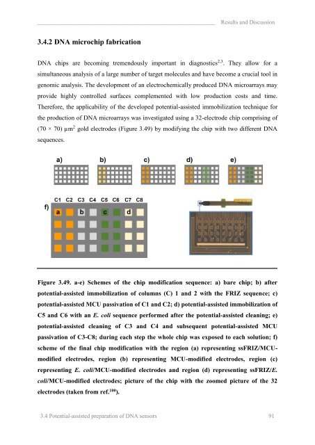
by initially immobilizing a DNA sequence 1 (20-mer, “FRIZ sequence” in the further text) on<br />
the first two columns of the chip for 30 s with a subsequent passivation with MCU for 1 min<br />
(Figure 3.49, a-c). Since the whole chip was immersed in the same solution the other electrodes<br />
were subjected to immobilization at OCP. In order to prevent any undesired signal on these<br />
columns, prior to the immobilization with the sequence 2 (42-mer, “E. coli sequence”) columns<br />
5 and 6 were cleaned by the potential-assisted desorption for 5 s. Afterwards, they were<br />
modified with an E. coli sequence for 30 s (Figure 3.49, d). Subsequently, columns 3 and 4<br />
were cleaned with the potential-assisted desorption (5 s) and finally columns 3-8 were<br />
passivated with MCU (Figure 3.49, e). It should be noted that the aim of the experiment was<br />
not the optimization of the assay parameters but rather a proof of concept. Therefore, the<br />
employed immobilization and passivation times are not optimized. Independently it was<br />
observed that an immobilization time of only 5 s and a passivation time of 3 s are sufficient to<br />
achieve optimal DNA coverage for the employed system and the desired passivation of the<br />
electrode surface, respectively (data not shown). Compared to macro electrodes, the optimal<br />
modification time is much shorter, which can be explained by the improved diffusion profile of<br />
microelectrodes.<br />
By designing the experiment in the explained manner the obtained DNA chip is supposed to<br />
consist of 4 different regions: region a modified with FRIZ/MCU, region b modified only with<br />
MCU, region c modified with E. coli/MCU and region d where both FRIZ and E. coli<br />
sequences are immobilized by incubation at OCP and a subsequent passivation is done by the<br />
potential-assisted method (Figure 3.49, f). The whole chip was exposed to each solution leaving<br />
the possibility of contamination between different regions. Therefore, to verify the quality of<br />
preparation, the chip was subjected to hybridization using both target DNA sequences, FRIZ<br />
and E. coli tDNA, labelled with ferrocene. The results obtained by FSCV are shown in Figure<br />
3.50. In general, it can be observed that each region that was exposed to the same conditions<br />
shows reproducible results among individual electrodes (Figure 3.50, a).<br />
Figure 3.50, b and c compare representative electrodes from each region upon hybridization<br />
with FRIZ and E. coli tDNA sequences, respectively. In order to understand what these figures<br />
show, each region is discussed for both cases. Region a is the only region where FRIZ ssDNA<br />
immobilization was performed via the potential-assisted method and therefore should show the<br />
hybridization signal from Fc-labelled FRIZ-tDNA. Indeed, this is observed on each electrode<br />
3.4 Potential-assisted preparation of DNA sensors 92