Display and Interface Design
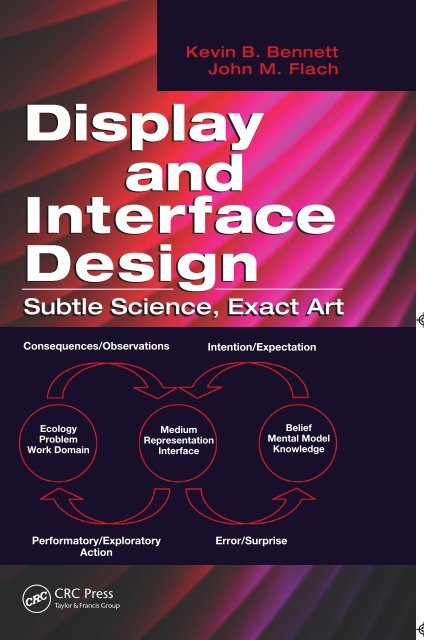
Kevin B. Bennett John M. Flach Display and Interface Design Subtle Science, Exact Art Consequences/Observations Intention/Expectation Ecology Problem Work Domain Medium Representation Interface Belief Mental Model Knowledge Performatory/Exploratory Action Error/Surprise
- Page 2: Display and Interface Design Subtle
- Page 5 and 6: CRC Press Taylor & Francis Group 60
- Page 8 and 9: Contents Preface...................
- Page 10 and 11: Contents ix 4.5.2 Cognitive Illusio
- Page 12 and 13: Contents xi 8.2.4 Redundant Conditi
- Page 14 and 15: Contents xiii 11.4 The Total Energy
- Page 16 and 17: Contents xv 15. Design Principles:
- Page 18: Contents xvii 18. A New Way of Seei
- Page 21 and 22: xx Preface as well as an understand
- Page 24 and 25: Acknowledgments We would like to th
- Page 26: The Authors Kevin B. Bennett is a p
- Page 29 and 30: 2 Display and Interface Design: Sub
- Page 31 and 32: 4 Display and Interface Design: Sub
- Page 33 and 34: 6 Display and Interface Design: Sub
- Page 35 and 36: 8 Display and Interface Design: Sub
- Page 37 and 38: 10 Display and Interface Design: Su
- Page 39 and 40: 12 Display and Interface Design: Su
- Page 42 and 43: 2 A Meaning Processing Approach 2.1
- Page 44 and 45: A Meaning Processing Approach 17 mo
- Page 46 and 47: A Meaning Processing Approach 19 th
- Page 48 and 49: A Meaning Processing Approach 21 Si
- Page 50 and 51: A Meaning Processing Approach 23 en
Kevin B. Bennett<br />
John M. Flach<br />
<strong>Display</strong><br />
<strong>and</strong><br />
<strong>Interface</strong><br />
<strong>Design</strong><br />
Subtle Science, Exact Art<br />
Consequences/Observations<br />
Intention/Expectation<br />
Ecology<br />
Problem<br />
Work Domain<br />
Medium<br />
Representation<br />
<strong>Interface</strong><br />
Belief<br />
Mental Model<br />
Knowledge<br />
Performatory/Exploratory<br />
Action<br />
Error/Surprise
<strong>Display</strong><br />
<strong>and</strong><br />
<strong>Interface</strong><br />
<strong>Design</strong><br />
Subtle Science, Exact Art
<strong>Display</strong><br />
<strong>and</strong><br />
<strong>Interface</strong><br />
<strong>Design</strong><br />
Subtle Science, Exact Art<br />
Kevin B. Bennett<br />
John M. Flach<br />
Boca Raton London New York<br />
CRC Press is an imprint of the<br />
Taylor & Francis Group, an informa business
CRC Press<br />
Taylor & Francis Group<br />
6000 Broken Sound Parkway NW, Suite 300<br />
Boca Raton, FL 33487-2742<br />
© 2011 by Taylor <strong>and</strong> Francis Group, LLC<br />
CRC Press is an imprint of Taylor & Francis Group, an Informa business<br />
No claim to original U.S. Government works<br />
Printed in the United States of America on acid-free paper<br />
10 9 8 7 6 5 4 3 2 1<br />
International St<strong>and</strong>ard Book Number-13: 978-1-4200-6439-1 (Ebook-PDF)<br />
This book contains information obtained from authentic <strong>and</strong> highly regarded sources. Reasonable<br />
efforts have been made to publish reliable data <strong>and</strong> information, but the author <strong>and</strong> publisher cannot<br />
assume responsibility for the validity of all materials or the consequences of their use. The authors <strong>and</strong><br />
publishers have attempted to trace the copyright holders of all material reproduced in this publication<br />
<strong>and</strong> apologize to copyright holders if permission to publish in this form has not been obtained. If any<br />
copyright material has not been acknowledged please write <strong>and</strong> let us know so we may rectify in any<br />
future reprint.<br />
Except as permitted under U.S. Copyright Law, no part of this book may be reprinted, reproduced,<br />
transmitted, or utilized in any form by any electronic, mechanical, or other means, now known or<br />
hereafter invented, including photocopying, microfilming, <strong>and</strong> recording, or in any information storage<br />
or retrieval system, without written permission from the publishers.<br />
For permission to photocopy or use material electronically from this work, please access www.copyright.com<br />
(http://www.copyright.com/) or contact the Copyright Clearance Center, Inc. (CCC), 222<br />
Rosewood Drive, Danvers, MA 01923, 978-750-8400. CCC is a not-for-profit organization that provides<br />
licenses <strong>and</strong> registration for a variety of users. For organizations that have been granted a photocopy<br />
license by the CCC, a separate system of payment has been arranged.<br />
Trademark Notice: Product or corporate names may be trademarks or registered trademarks, <strong>and</strong> are<br />
used only for identification <strong>and</strong> explanation without intent to infringe.<br />
Visit the Taylor & Francis Web site at<br />
http://www.taylor<strong>and</strong>francis.com<br />
<strong>and</strong> the CRC Press Web site at<br />
http://www.crcpress.com
To Jens Rasmussen for his inspiration <strong>and</strong> guidance.<br />
© 2011 by Taylor & Francis Group, LLC
Contents<br />
Preface................................................................................................................... xix<br />
Acknowledgments.............................................................................................xxiii<br />
The Authors......................................................................................................... xxv<br />
1. Introduction to Subtle Science, Exact Art..................................................1<br />
1.1 Introduction............................................................................................1<br />
1.2 Theoretical Orientation.........................................................................2<br />
1.2.1 Cognitive Systems Engineering: Ecological<br />
<strong>Interface</strong> <strong>Design</strong>........................................................................3<br />
1.2.2 With a Psychological Twist.....................................................4<br />
1.3 Basic versus Applied Science...............................................................5<br />
1.3.1 Too Theoretical!........................................................................5<br />
1.3.2 Too Applied!..............................................................................6<br />
1.4 Pasteur’s Quadrant................................................................................7<br />
1.4.1 The Wright Brothers in the Quadrant...................................8<br />
1.4.2 This Book <strong>and</strong> the Quadrant..................................................9<br />
1.5 Overview.............................................................................................. 10<br />
1.6 Summary.............................................................................................. 11<br />
References........................................................................................................ 13<br />
2. A Meaning Processing Approach.............................................................. 15<br />
2.1 Introduction.......................................................................................... 15<br />
2.2 Two Alternative Paradigms for <strong>Interface</strong> <strong>Design</strong>............................ 16<br />
2.2.1 The Dyadic Paradigm............................................................ 16<br />
2.2.2 The Triadic Paradigm............................................................ 17<br />
2.2.3 Implications for <strong>Interface</strong> <strong>Design</strong>......................................... 18<br />
2.3 Two Paths to Meaning.........................................................................20<br />
2.3.1 Conventional Wisdom: Meaning = Interpretation............20<br />
2.3.2 An Ecological or Situated Perspective:<br />
Meaning = Affordance..........................................................22<br />
2.3.3 Information versus Meaning................................................26<br />
2.4 The Dynamics of Meaning Processing.............................................30<br />
2.4.1 The Regulator Paradox..........................................................30<br />
2.4.2 Perception <strong>and</strong> Action in Meaning Processing.................. 31<br />
2.4.3 Inductive, Deductive, <strong>and</strong> Abductive Forms of<br />
Knowing..................................................................................33<br />
2.5 Conclusion............................................................................................34<br />
2.6 Summary..............................................................................................38<br />
References........................................................................................................38<br />
© 2011 by Taylor & Francis Group, LLC<br />
vii
viii<br />
Contents<br />
3. The Dynamics of Situations....................................................................... 41<br />
3.1 Introduction.......................................................................................... 41<br />
3.2 The Problem State Space.....................................................................42<br />
3.2.1 The State Space for the Game of Fifteen..............................43<br />
3.2.2 The State Space for a Simple Manual Control Task...........46<br />
3.2.3 Implications for <strong>Interface</strong> <strong>Design</strong>.........................................50<br />
3.3 Levels of Abstraction........................................................................... 51<br />
3.3.1 Two Analytical Frameworks for Modeling<br />
Abstraction.............................................................................. 52<br />
3.4 Computational Level of Abstraction................................................. 52<br />
3.4.1 Functional Purpose................................................................54<br />
3.4.2 Abstract Function...................................................................55<br />
3.4.3 Summary.................................................................................56<br />
3.5 Algorithm or General Function Level of Abstraction....................57<br />
3.6 Hardware Implementation.................................................................58<br />
3.6.1 Physical Function...................................................................58<br />
3.6.2 Physical Form..........................................................................59<br />
3.7 Putting It All Together........................................................................59<br />
3.7.1 Abstraction, Aggregation, <strong>and</strong> Progressive<br />
Deepening...............................................................................60<br />
3.7.2 Implications for Work Domain Analyses........................... 61<br />
3.7.3 Summary................................................................................. 62<br />
3.8 Conclusion............................................................................................64<br />
References........................................................................................................65<br />
4. The Dynamics of Awareness...................................................................... 67<br />
4.1 Introduction.......................................................................................... 67<br />
4.1.1 Zeroing In as a Form of Abduction.....................................68<br />
4.1.2 Chunking of Domain Structure........................................... 70<br />
4.1.3 Implications for <strong>Interface</strong> <strong>Design</strong>.........................................71<br />
4.2 A Model of Information Processing..................................................72<br />
4.2.1 Decision Ladder: Shortcuts in Information<br />
Processing................................................................................73<br />
4.3 Automatic Processing......................................................................... 76<br />
4.3.1 Varied <strong>and</strong> Consistent Mappings.........................................77<br />
4.3.2 Two Modes of Processing......................................................77<br />
4.3.3 Relationship to Decision Ladder..........................................78<br />
4.3.4 Implications for <strong>Interface</strong> <strong>Design</strong>.........................................79<br />
4.4 Direct Perception.................................................................................80<br />
4.4.1 Invariance as a Form of Consistent Mapping....................80<br />
4.4.2 Perception <strong>and</strong> the Role of Inferential Processes...............82<br />
4.4.3 Implications for <strong>Interface</strong> <strong>Design</strong>.........................................84<br />
4.5 Heuristic Decision Making................................................................85<br />
4.5.1 Optimization under Constraints..........................................85<br />
© 2011 by Taylor & Francis Group, LLC
Contents<br />
ix<br />
4.5.2 Cognitive Illusions.................................................................86<br />
4.5.3 Ecological Rationality............................................................87<br />
4.5.3.1 Less Is More.............................................................87<br />
4.5.3.2 Take the Best............................................................88<br />
4.5.3.3 One-Reason Decision Making..............................88<br />
4.6 Summary <strong>and</strong> Conclusions................................................................89<br />
References........................................................................................................90<br />
5. The Dynamics of Situation Awareness....................................................93<br />
5.1 Introduction..........................................................................................93<br />
5.2 Representation Systems <strong>and</strong> Modes of Behavior............................94<br />
5.2.1 Signal Representations/Skill-Based Behavior....................95<br />
5.2.2 Sign Representations/Rule-Based Behavior.......................96<br />
5.2.3 Symbol Representations/Knowledge-Based<br />
Behaviors.................................................................................97<br />
5.3 Representations, Modes, <strong>and</strong> the Decision Ladder........................99<br />
5.3.1 Skill-Based Synchronization.................................................99<br />
5.3.2 Rule-Based Shortcuts........................................................... 101<br />
5.3.3 Knowledge-Based Reasoning............................................. 101<br />
5.3.4 Summary............................................................................... 101<br />
5.4 Ecological <strong>Interface</strong> <strong>Design</strong> (EID).................................................... 102<br />
5.4.1 Complementary Perspectives on EID................................ 103<br />
5.4.2 Qualifications <strong>and</strong> Potential<br />
Misunderst<strong>and</strong>ings.............................................................. 104<br />
5.5 Summary............................................................................................ 105<br />
References...................................................................................................... 106<br />
6. A Framework for Ecological <strong>Interface</strong> <strong>Design</strong> (EID)........................... 109<br />
6.1 Introduction........................................................................................ 109<br />
6.2 Fundamental Principles.................................................................... 111<br />
6.2.1 Direct Manipulation/Direct Perception........................... 112<br />
6.3 General Domain Constraints........................................................... 115<br />
6.3.1 Source of Regularity: Correspondence-Driven<br />
Domains................................................................................. 116<br />
6.3.2 Source of Regularity: Coherence-Driven<br />
Domains................................................................................. 117<br />
6.3.3 Summary............................................................................... 118<br />
6.4 General <strong>Interface</strong> Constraints.......................................................... 119<br />
6.4.1 Propositional Representations............................................ 119<br />
6.4.2 Metaphors.............................................................................. 120<br />
6.4.3 Analogies...............................................................................122<br />
6.4.4 Metaphor versus Analogy...................................................122<br />
6.4.5 Analog (versus Digital)........................................................123<br />
6.5 <strong>Interface</strong> <strong>Design</strong> Strategies............................................................... 124<br />
© 2011 by Taylor & Francis Group, LLC
x<br />
Contents<br />
6.6 Ecological <strong>Interface</strong> <strong>Design</strong>: Correspondence-Driven<br />
Domains.............................................................................................. 126<br />
6.6.1 Nested Hierarchies............................................................... 127<br />
6.6.2 Nested Hierarchies in the <strong>Interface</strong>: Analogical<br />
Representations.................................................................... 129<br />
6.7 Ecological <strong>Interface</strong> <strong>Design</strong>: Coherence-Driven Domains.......... 132<br />
6.7.1 Objective Properties: Effectivities...................................... 133<br />
6.7.2 Nested Hierarchies in the <strong>Interface</strong>: Metaphorical<br />
Representations.................................................................... 134<br />
6.8 Summary............................................................................................ 136<br />
References...................................................................................................... 139<br />
7. <strong>Display</strong> <strong>Design</strong>: Building a Conceptual Base....................................... 141<br />
7.1 Introduction........................................................................................ 141<br />
7.2 Psychophysical Approach................................................................ 142<br />
7.2.1 Elementary Graphical Perception Tasks........................... 143<br />
7.2.2 Limitations............................................................................ 145<br />
7.3 Aesthetic, Graphic Arts Approach.................................................. 146<br />
7.3.1 Quantitative Graphs............................................................. 146<br />
7.3.2 Visualizing Information...................................................... 149<br />
7.3.3 Limitations............................................................................ 152<br />
7.4 Visual Attention................................................................................. 152<br />
7.5 Naturalistic Decision Making.......................................................... 152<br />
7.5.1 Recognition-Primed Decisions........................................... 153<br />
7.5.1.1 Stages in RPD........................................................ 153<br />
7.5.1.2 Implications for Computer-Mediated<br />
Decision Support................................................... 155<br />
7.6 Problem Solving................................................................................. 155<br />
7.6.1 Gestalt Perspective............................................................... 156<br />
7.6.1.1 Gestalts <strong>and</strong> Problem Solving............................. 156<br />
7.6.1.2 Problem Solving as Transformation<br />
of Gestalt................................................................ 157<br />
7.6.2 The Power of Representations............................................ 159<br />
7.6.3 Functional Fixedness........................................................... 160<br />
7.6.4 The Double-Edged Sword of Representations................. 164<br />
7.7 Summary............................................................................................ 165<br />
References...................................................................................................... 166<br />
8. Visual Attention <strong>and</strong> Form Perception................................................... 169<br />
8.1 Introduction........................................................................................ 169<br />
8.2 Experimental Tasks <strong>and</strong> Representative Results.......................... 170<br />
8.2.1 Control Condition................................................................. 171<br />
8.2.2 Selective Attention............................................................... 173<br />
8.2.3 Divided Attention................................................................. 173<br />
© 2011 by Taylor & Francis Group, LLC
Contents<br />
xi<br />
8.2.4 Redundant Condition.......................................................... 174<br />
8.2.5 A Representative Experiment............................................. 174<br />
8.3 An Interpretation Based on Perceptual Objects <strong>and</strong><br />
Perceptual Glue.................................................................................. 175<br />
8.3.1 Gestalt Laws of Grouping................................................... 176<br />
8.3.2 Benefits <strong>and</strong> Costs for Perceptual Objects........................ 179<br />
8.4 Configural Stimulus Dimensions <strong>and</strong> Emergent Features.......... 180<br />
8.4.1 The Dimensional Structure of Perceptual Input.............. 181<br />
8.4.1.1 Separable Dimensions.......................................... 181<br />
8.4.1.2 Integral Dimensions............................................. 182<br />
8.4.1.3 Configural Dimensions........................................ 183<br />
8.4.2 Emergent Features; Perceptual Salience;<br />
Nested Hierarchies............................................................... 184<br />
8.4.3 Configural Superiority Effect............................................. 185<br />
8.4.3.1 Salient Emergent Features................................... 185<br />
8.4.3.2 Inconspicuous Emergent Features..................... 187<br />
8.4.4 The Importance of Being Dynamic.................................... 188<br />
8.5 An Interpretation Based on Configurality <strong>and</strong><br />
Emergent Features............................................................................. 189<br />
8.5.1 Divided Attention................................................................. 190<br />
8.5.2 Control Condition................................................................. 191<br />
8.5.3 Selective Condition............................................................... 191<br />
8.6 Summary............................................................................................ 192<br />
References...................................................................................................... 195<br />
9. Semantic Mapping versus Proximity Compatibility........................... 197<br />
9.1 Introduction........................................................................................ 197<br />
9.2 Proximity Compatibility Principle.................................................. 198<br />
9.2.1 PCP <strong>and</strong> Divided Attention................................................ 198<br />
9.2.2 PCP <strong>and</strong> Focused Attention................................................200<br />
9.2.3 Representative PCP Study................................................... 201<br />
9.2.4 Summary of PCP..................................................................203<br />
9.3 Comparative Literature Review......................................................203<br />
9.3.1 Pattern for Divided Attention.............................................203<br />
9.3.2 Pattern for Focused Attention............................................203<br />
9.4 Semantic Mapping............................................................................. 207<br />
9.4.1 Semantic Mapping <strong>and</strong> Divided Attention......................208<br />
9.4.1.1 Mappings Matter!................................................. 210<br />
9.4.1.2 Configurality, Not Object Integrality: I............. 212<br />
9.4.1.3 Configurality, Not Object Integrality: II............ 215<br />
9.4.1.4 Summary................................................................220<br />
9.4.2 Semantic Mapping <strong>and</strong> Focused Attention......................220<br />
9.4.2.1 <strong>Design</strong> Techniques to Offset<br />
Potential Costs....................................................... 221<br />
© 2011 by Taylor & Francis Group, LLC
xii<br />
Contents<br />
9.4.2.2 Visual Structure in Focused Attention..............223<br />
9.4.2.3 Revised Perspective on Focused<br />
Attention................................................................226<br />
9.5 <strong>Design</strong> Strategies in Supporting Divided <strong>and</strong><br />
Focused Attention.............................................................................226<br />
9.6 PCP Revisited.....................................................................................227<br />
References......................................................................................................229<br />
10. <strong>Design</strong> Tutorial: Configural Graphics for Process Control................ 231<br />
10.1 Introduction........................................................................................ 231<br />
10.2 A Simple Domain from Process Control........................................ 232<br />
10.2.1 Low-Level Data (Process Variables)................................... 232<br />
10.2.2 High-Level Properties (Process Constraints)................... 232<br />
10.3 An Abstraction Hierarchy Analysis...............................................234<br />
10.4 Direct Perception...............................................................................236<br />
10.4.1 Mapping Domain Constraints into Geometrical<br />
Constraints............................................................................236<br />
10.4.1.1 General Work Activities <strong>and</strong> Functions............238<br />
10.4.1.2 Priority Measures <strong>and</strong> Abstract<br />
Functions................................................................238<br />
10.4.1.3 Goals <strong>and</strong> Purposes.............................................. 239<br />
10.4.1.4 Physical Processes................................................. 239<br />
10.4.1.5 Physical Appearance, Location, <strong>and</strong><br />
Configuration........................................................ 239<br />
10.4.2 Support for Skill-, Rule-, <strong>and</strong> Knowledge-Based<br />
Behaviors............................................................................... 240<br />
10.4.2.1 Skill-Based Behavior/Signals.............................. 240<br />
10.4.2.2 Rule-Based Behavior/Signs................................. 240<br />
10.4.2.3 Knowledge-Based Behavior/Symbols............... 243<br />
10.4.3 Alternative Mappings.......................................................... 249<br />
10.4.3.1 Separable <strong>Display</strong>s................................................ 252<br />
10.4.3.2 Configural <strong>Display</strong>s..............................................254<br />
10.4.3.3 Integral <strong>Display</strong>s...................................................255<br />
10.4.3.4 Summary................................................................255<br />
10.4.4 Temporal Information..........................................................256<br />
10.4.4.1 The Time Tunnels Technique.............................. 257<br />
10.5 Direct Manipulation..........................................................................260<br />
10.6 Summary............................................................................................ 262<br />
References......................................................................................................263<br />
11. <strong>Design</strong> Tutorial: Flying within the Field of Safe Travel.....................265<br />
11.1 Introduction........................................................................................265<br />
11.2 The Challenge of Blind Flight.......................................................... 270<br />
11.3 The Wright Configural Attitude <strong>Display</strong> (WrightCAD)..............272<br />
© 2011 by Taylor & Francis Group, LLC
Contents<br />
xiii<br />
11.4 The Total Energy Path <strong>Display</strong>........................................................277<br />
11.5 Summary............................................................................................ 282<br />
References......................................................................................................284<br />
12. Metaphor: Leveraging Experience........................................................... 287<br />
12.1 Introduction........................................................................................ 287<br />
12.2 Spatial Metaphors <strong>and</strong> Iconic Objects............................................288<br />
12.2.1 The Power of Metaphors......................................................289<br />
12.2.2 The Trouble with Metaphors..............................................289<br />
12.3 Skill Development.............................................................................290<br />
12.3.1 Assimilation.......................................................................... 291<br />
12.3.2 Accommodation.................................................................... 292<br />
12.3.3 <strong>Interface</strong> Support for Learning by Doing......................... 293<br />
12.4 Shaping Expectations........................................................................ 295<br />
12.4.1 Know Thy User..................................................................... 297<br />
12.5 Abduction: The Dark Side................................................................ 298<br />
12.5.1 Forms of Abductive Error...................................................299<br />
12.5.2 Minimizing Negative Transfer...........................................300<br />
12.6 Categories of Metaphors...................................................................300<br />
12.7 Summary............................................................................................305<br />
References......................................................................................................309<br />
13. <strong>Design</strong> Tutorial: Mobile Phones <strong>and</strong> PDAs........................................... 311<br />
13.1 Introduction........................................................................................ 311<br />
13.2 Abstraction Hierarchy Analysis...................................................... 314<br />
13.3 The iPhone <strong>Interface</strong>.......................................................................... 316<br />
13.3.1 Direct Perception.................................................................. 316<br />
13.3.1.1 Forms Level........................................................... 316<br />
13.3.1.2 Views Level............................................................ 317<br />
13.3.1.3 Work Space Level.................................................. 318<br />
13.3.2 Direct Manipulation............................................................. 320<br />
13.3.2.1 Tap........................................................................... 321<br />
13.3.2.2 Flick......................................................................... 321<br />
13.3.2.3 Double Tap.............................................................322<br />
13.3.2.4 Drag........................................................................322<br />
13.3.2.5 Pinch In/Pinch Out.............................................. 324<br />
13.4 Support for Various Modes of Behavior......................................... 324<br />
13.4.1 Skill-Based Behavior............................................................ 324<br />
13.4.2 Rule-Based Behavior............................................................ 326<br />
13.4.3 Knowledge-Based Behavior................................................ 328<br />
13.5 Broader Implications for <strong>Interface</strong> <strong>Design</strong>..................................... 329<br />
13.5.1 To Menu or Not to Menu? (Is That the Question? Is<br />
There a Rub?).........................................................................330<br />
13.6 Summary............................................................................................333<br />
References......................................................................................................333<br />
© 2011 by Taylor & Francis Group, LLC
xiv<br />
Contents<br />
14. <strong>Design</strong> Tutorial: Comm<strong>and</strong> <strong>and</strong> Control................................................335<br />
14.1 Introduction........................................................................................335<br />
14.2 Abstraction Hierarchy Analysis of Military Comm<strong>and</strong><br />
<strong>and</strong> Control......................................................................................... 337<br />
14.2.1 Goals, Purposes, <strong>and</strong> Constraints...................................... 337<br />
14.2.2 Priority Measures <strong>and</strong> Abstract Functions.......................339<br />
14.2.3 General Work Activities <strong>and</strong> Functions............................339<br />
14.2.4 Physical Activities in Work; Physical Processes<br />
of Equipment.........................................................................339<br />
14.2.5 Appearance, Location, <strong>and</strong> Configuration of<br />
Material Objects....................................................................340<br />
14.2.6 Aggregation Hierarchy........................................................340<br />
14.3 Decision Making................................................................................340<br />
14.3.1 Military Decision-Making Process<br />
(or Analytical Process).........................................................341<br />
14.3.1.1 Situation Analysis.................................................341<br />
14.3.1.2 Develop Courses of Action..................................341<br />
14.3.1.3 Planning <strong>and</strong> Execution.......................................343<br />
14.3.2 Intuitive Decision Making (or Naturalistic<br />
Decision Making).................................................................344<br />
14.4 Direct Perception...............................................................................345<br />
14.4.1 Friendly Combat Resources <strong>Display</strong>.................................347<br />
14.4.2 Enemy Combat Resources <strong>Display</strong>....................................348<br />
14.4.3 Force Ratio <strong>Display</strong>..............................................................350<br />
14.4.4 Force Ratio Trend <strong>Display</strong>................................................... 352<br />
14.4.4.1 A Brief Digression.................................................354<br />
14.4.5 Spatial Synchronization Matrix <strong>Display</strong>...........................355<br />
14.4.6 Temporal Synchronization Matrix <strong>Display</strong>......................356<br />
14.4.7 Plan Review Mode <strong>and</strong> <strong>Display</strong>s.......................................358<br />
14.4.8 Alternative Course of Action <strong>Display</strong>...............................360<br />
14.5 Direct Manipulation.......................................................................... 361<br />
14.5.1 Synchronization Points........................................................ 362<br />
14.5.2 Levels of Aggregation.......................................................... 362<br />
14.5.2.1 Aggregation Control/<strong>Display</strong>............................. 362<br />
14.5.2.2 Control of Force Icons..........................................363<br />
14.6 Skill-Based Behavior.........................................................................364<br />
14.7 Rule-Based Behavior.........................................................................365<br />
14.8 Knowledge-Based Behavior.............................................................365<br />
14.9 Evaluation........................................................................................... 367<br />
14.9.1 Direct Perception.................................................................. 367<br />
14.9.2 Situation Assessment; Decision Making...........................368<br />
14.10 Summary............................................................................................ 370<br />
References...................................................................................................... 371<br />
© 2011 by Taylor & Francis Group, LLC
Contents<br />
xv<br />
15. <strong>Design</strong> Principles: Visual Momentum................................................... 375<br />
15.1 Introduction........................................................................................ 375<br />
15.2 Visual Momentum.............................................................................377<br />
15.2.1 <strong>Design</strong> Strategies.................................................................. 378<br />
15.2.1.1 Fixed Format Data Replacement......................... 378<br />
15.2.1.2 Long Shot............................................................... 379<br />
15.2.1.3 Perceptual L<strong>and</strong>marks......................................... 379<br />
15.2.1.4 <strong>Display</strong> Overlap....................................................380<br />
15.2.1.5 Spatial Structure<br />
(Spatial Representation/Cognition)................... 381<br />
15.2.2 <strong>Interface</strong> Levels..................................................................... 381<br />
15.3 VM in the Work Space...................................................................... 382<br />
15.3.1 The BookHouse <strong>Interface</strong>....................................................383<br />
15.3.1.1 Spatial Structure...................................................384<br />
15.3.1.2 <strong>Display</strong> Overlap....................................................385<br />
15.3.1.3 Perceptual L<strong>and</strong>marks.........................................386<br />
15.3.1.4 Fixed Format Data Replacement.........................386<br />
15.3.2 The iPhone <strong>Interface</strong>............................................................ 387<br />
15.3.2.1 Spatial Structure................................................... 387<br />
15.3.2.2 Long Shot...............................................................389<br />
15.3.2.3 Fixed Format Data Replacement.........................389<br />
15.3.2.4 Perceptual L<strong>and</strong>marks.........................................390<br />
15.3.3 Spatial Cognition/Way-Finding.........................................390<br />
15.3.3.1 L<strong>and</strong>mark Knowledge......................................... 391<br />
15.3.3.2 Route Knowledge.................................................. 392<br />
15.3.3.3 Survey Knowledge................................................ 392<br />
15.4 VM in Views....................................................................................... 394<br />
15.4.1 The RAPTOR <strong>Interface</strong>........................................................ 395<br />
15.4.1.1 Spatial Dedication; Layering <strong>and</strong><br />
Separation.............................................................. 395<br />
15.4.1.2 Long Shot............................................................... 395<br />
15.4.1.3 Perceptual L<strong>and</strong>marks......................................... 397<br />
15.4.1.4 Fixed Format Data Replacement......................... 398<br />
15.4.1.5 Overlap................................................................... 399<br />
15.5 VM in Forms.......................................................................................400<br />
15.5.1 A Representative Configural <strong>Display</strong>................................ 401<br />
15.5.1.1 Fixed Format Data Replacement.........................402<br />
15.5.1.2 Perceptual L<strong>and</strong>marks.........................................402<br />
15.5.1.3 Long Shot...............................................................403<br />
15.5.1.4 Overlap...................................................................403<br />
15.5.1.5 Section Summary..................................................403<br />
15.6 Summary............................................................................................404<br />
References......................................................................................................405<br />
© 2011 by Taylor & Francis Group, LLC
xvi<br />
Contents<br />
16. Measurement................................................................................................407<br />
16.1 Introduction........................................................................................407<br />
16.2 Paradigmatic Commitments: Control versus Generalization.....408<br />
16.2.1 Dyadic Commitments..........................................................408<br />
16.2.2 Triadic Commitments..........................................................408<br />
16.2.3 Parsing Complexity.............................................................. 410<br />
16.3 What Is the System?........................................................................... 411<br />
16.3.1 Measuring Situations........................................................... 413<br />
16.3.1.1 The Abstraction (Measurement) Hierarchy...... 414<br />
16.3.2 Measuring Awareness......................................................... 416<br />
16.3.2.1 Decision Ladder; SRK........................................... 417<br />
16.3.3 Measuring Performance...................................................... 417<br />
16.3.3.1 Multiple, Context-Dependent Indices................ 418<br />
16.3.3.2 Process <strong>and</strong> Outcome........................................... 419<br />
16.3.3.3 Hierarchically Nested..........................................420<br />
16.4 Synthetic Task Environments..........................................................420<br />
16.4.1 Not Just Simulation..............................................................420<br />
16.4.2 Coupling between Measurement Levels.......................... 421<br />
16.4.3 Fidelity...................................................................................422<br />
16.5 Conclusion..........................................................................................423<br />
References......................................................................................................425<br />
17. <strong>Interface</strong> Evaluation....................................................................................427<br />
17.1 Introduction........................................................................................427<br />
17.2 Cognitive Systems Engineering Evaluative Framework..............428<br />
17.2.1 Boundary 1: Controlled Mental Processes........................429<br />
17.2.2 Boundary 2: Controlled Cognitive Tasks..........................430<br />
17.2.3 Boundary 3: Controlled Task Situation.............................430<br />
17.2.4 Boundary 4: Complex Work Environments..................... 431<br />
17.2.5 Boundary 5: Experiments in Actual Work<br />
Environment......................................................................... 432<br />
17.2.6 Summary............................................................................... 432<br />
17.3 Representative Research Program; Multiboundary Results.......432<br />
17.3.1 Synthetic Task Environment for Process Control............433<br />
17.3.2 Boundary Level 1 Evaluation.............................................434<br />
17.3.3 Boundary Levels 2 <strong>and</strong> 3.....................................................436<br />
17.3.4 Boundary Levels 1 <strong>and</strong> 3.....................................................438<br />
17.4 Conventional Rules <strong>and</strong> Experimental Results.............................441<br />
17.4.1 Match with Dyadic Conventional Rules...........................441<br />
17.4.2 Match with Triadic Conventional Rules...........................442<br />
17.5 Broader Concerns Regarding Generalization...............................444<br />
17.6 Conclusion..........................................................................................446<br />
References......................................................................................................448<br />
© 2011 by Taylor & Francis Group, LLC
Contents<br />
xvii<br />
18. A New Way of Seeing?............................................................................... 451<br />
18.1 Introduction........................................................................................ 451<br />
18.2 A Paradigm Shift <strong>and</strong> Its Implications........................................... 451<br />
18.2.1 Chunking: A Representative Example of<br />
Reinterpretation....................................................................453<br />
18.2.2 Summary...............................................................................454<br />
18.3 <strong>Interface</strong> <strong>Design</strong>.................................................................................454<br />
18.3.1 Constraint Mappings for Correspondence-Driven<br />
Domains.................................................................................455<br />
18.3.2 Constraint Mappings for Coherence-Driven<br />
Domains.................................................................................456<br />
18.3.3 The Eco-Logic of Work Domains.......................................458<br />
18.3.4 Productive Thinking in Work Domains...........................458<br />
18.4 Looking over the Horizon................................................................459<br />
18.4.1 Mind, Matter, <strong>and</strong> What Matters.......................................460<br />
18.4.2 Information Processing Systems........................................ 461<br />
18.4.3 Meaning Processing Systems............................................. 461<br />
References...................................................................................................... 462<br />
Index..............................................................................................................465<br />
© 2011 by Taylor & Francis Group, LLC
Preface<br />
This book is about display <strong>and</strong> interface design. It is the product of over<br />
60 years of combined experience studying, implementing, <strong>and</strong> teaching<br />
about performance in human–technology systems. Great strides have been<br />
made in interface design since the early 1980s, when we first began thinking<br />
about the associated challenges. Technological advances in hardware <strong>and</strong><br />
software now provide the potential to design interfaces that are both powerful<br />
<strong>and</strong> easy to use. Yet, the frustrations <strong>and</strong> convoluted “work-arounds”<br />
that are often still encountered make it clear that there is substantial room<br />
for improvement. Over the years, we have acquired a deep appreciation for<br />
the complexity <strong>and</strong> difficulty of building effective interfaces; it is reflected in<br />
the content of this book. As a result, you are likely to find it to be decidedly<br />
different from most books on the topic.<br />
We view the interface as a tool that will help an individual accomplish<br />
his or her work efficiently <strong>and</strong> pleasurably; it is a form of decision-making<br />
<strong>and</strong> problem-solving support. As such, a recurring question concerns the<br />
relation between the structure of problem representations <strong>and</strong> the quality of<br />
performance. A change in how a problem is represented can have a marked<br />
effect on the quality of performance. This relation is interesting to us as cognitive<br />
psychologists <strong>and</strong> as cognitive systems engineers.<br />
As cognitive psychologists, we believe that the relationship between the<br />
structure of representations <strong>and</strong> the quality of performance has important<br />
implications for underst<strong>and</strong>ing the basic dynamics of cognition. It suggests<br />
that there is an intimate, circular coupling between perception–action <strong>and</strong><br />
between situation–awareness that contrasts with conventional approaches<br />
to cognition (where performance is viewed as a series of effectively independent<br />
stages of general, context-independent information processes). We<br />
believe that the coupling between perception <strong>and</strong> action (i.e., the ability to<br />
“see” the world in relation to constraints on action) <strong>and</strong> between situation<br />
<strong>and</strong> awareness (i.e., the ability to make sense of complex situations) depend<br />
critically on the structure of representations. Thus, in exploring the nature<br />
of representations, we believe that we are gaining important insight into<br />
human cognition.<br />
As cognitive engineers, we believe that the relation between representations<br />
<strong>and</strong> the quality of performance have obvious implications for the design<br />
of interfaces to support human work. The design challenge is to enhance<br />
perspicuity <strong>and</strong> awareness so that action <strong>and</strong> situation constraints are wellspecified<br />
relative to the dem<strong>and</strong>s of a work ecology. The approach is to design<br />
representations so that there is an explicit mapping between the patterns in<br />
the representation <strong>and</strong> the action <strong>and</strong> situation constraints. Of course, this<br />
implies an analysis of work domain situations to identify these constraints,<br />
© 2011 by Taylor & Francis Group, LLC<br />
xix
xx<br />
Preface<br />
as well as an underst<strong>and</strong>ing of awareness to know what patterns are likely<br />
to be salient. We believe that the quality of representing the work domain<br />
constraints will ultimately determine effectivity <strong>and</strong> efficiency; that is, it will<br />
determine the quality of performance <strong>and</strong> the level of effort required.<br />
Intended Audience<br />
The primary target audience for this book is students in human factors <strong>and</strong><br />
related disciplines (including psychology, engineering, computer science,<br />
industrial design, <strong>and</strong> industrial/organizational psychology). This book is<br />
an integration of our notes for the courses that we teach in interface design<br />
<strong>and</strong> cognitive systems engineering. Our goal is to train students to appreciate<br />
basic theory in cognitive science <strong>and</strong> to apply that theory in the design<br />
of technology <strong>and</strong> work organizations. We begin by constructing a theoretical<br />
foundation for approaching cognitive systems that integrates across<br />
situations, representations, <strong>and</strong> awareness—emphasizing the intimate interactions<br />
between them. The initial chapters of the book lay this foundation.<br />
We also hope to foster in our students a healthy appreciation for the value<br />
of basic empirical research in addressing questions about human performance.<br />
For example, in the middle chapters we provide extensive reviews of<br />
the research literature associated with visual attention in relation to the integral,<br />
separable, <strong>and</strong> configural properties of representations. Additionally,<br />
we try to prepare our students to immerse themselves in the complexity of<br />
practical design problems. Thus, we include several tutorial chapters that<br />
recount explorations of design in specific work domains.<br />
Finally, we try to impress on our students the intimate relation between<br />
basic <strong>and</strong> applied science. In fact, we emphasize that basic theory provides<br />
the strongest basis for generalization. The practical world <strong>and</strong> the scientific/<br />
academic world move at a very different pace. <strong>Design</strong>ers cannot wait for<br />
research programs to provide clear empirical answers to their questions. In<br />
order to participate in <strong>and</strong> influence design, we must be able to extrapolate our<br />
research to keep up with the dem<strong>and</strong>s of changing technologies <strong>and</strong> changing<br />
work domains. Theory is the most reliable basis for these extrapolations.<br />
Conversely, application can be the ultimate test of theory. It is typically<br />
a much stronger test than the laboratory, where the assumptions guiding<br />
a theory are often reified in the experimental methodology. Thus, laboratory<br />
research often ends up being demonstrations of plausibility, rather than<br />
strong tests of a theory.<br />
We believe this work will also be of interest to a much broader audience<br />
concerned with applying cognitive science to design technologies that<br />
enhance the quality of human work. This broader audience might identify<br />
with other labels for this enterprise: ergonomics, human factors engineering,<br />
© 2011 by Taylor & Francis Group, LLC
Preface<br />
xxi<br />
human–computer interaction (HCI), semantic computing, resilience engineering,<br />
industrial design, user-experience design, interaction design, etc.<br />
Our goals for this audience parallel the goals for our students: We want to<br />
provide a theoretical basis, an empirical basis, <strong>and</strong> a practical basis for framing<br />
the design questions.<br />
Note that this is not a “how to” book with recipes in answer to specific<br />
design questions (i.e., <strong>Interface</strong>s for Dummies). Rather, our goal is simply to help<br />
people to frame the questions well, with the optimism that a well-framed<br />
question is nearly answered. It is important for people to appreciate that we<br />
are dealing with complex problems <strong>and</strong> that there are no easy answers. Our<br />
goal is to help people to appreciate this complexity <strong>and</strong> to provide a theoretical<br />
context for parsing this complexity in ways that might lead to productive<br />
insights. As suggested by the title, our goal is to enhance the subtlety of the<br />
science <strong>and</strong> to enhance the exactness of the art with respect to designing<br />
effective cognitive systems.<br />
Kevin Bennett<br />
John Flach<br />
© 2011 by Taylor & Francis Group, LLC
Acknowledgments<br />
We would like to thank Don Norman, Jens Rasmussen, James Pomerantz,<br />
<strong>and</strong> a host of graduate students for their comments on earlier drafts. Larry<br />
Shattuck, Christopher Talcott, Silas Martinez, <strong>and</strong> Dan Hall were codevelopers<br />
<strong>and</strong> co-investigators in the research projects for the RAPTOR<br />
military comm<strong>and</strong> <strong>and</strong> control interface. Darby Patrick <strong>and</strong> Paul Jacques<br />
collaborated in the development <strong>and</strong> evaluation of the WrightCAD display<br />
concept. Matthijs Amelink was the designer of the Total Energy Path<br />
l<strong>and</strong>ing display in collaboration with Professor Max Mulder <strong>and</strong> Dr. Rene<br />
van Paassen in the faculty of Aeronautical Engineering at the Technical<br />
University of Delft.<br />
A special thanks from the first author to David Woods for his mentorship,<br />
collaborations, <strong>and</strong> incredible insights through the years. Thanks as well<br />
to Raja Parasuraman, who was as much friend as adviser during graduate<br />
school. Thanks to Jim Howard who introduced me to computers <strong>and</strong> taught<br />
me the importance of being precise. Thanks to Herb Colle, who created a<br />
great academic program <strong>and</strong> an environment that fosters success. Finally,<br />
thanks to my family <strong>and</strong> their patience during the long process of writing.<br />
The second author wants especially to thank Rich Jagacinski <strong>and</strong> Dean<br />
Owen, two mentors <strong>and</strong> teachers who set st<strong>and</strong>ards for quality far above<br />
my reach, who gave me the tools I needed to take the initial steps in that<br />
direction, <strong>and</strong> who gave me the confidence to persist even though the goal<br />
remains a distant target. Also, special thanks to Kim Vicente, the student<br />
who became my teacher. I also wish to acknowledge interactions with Jens<br />
Rasmussen, Max Mulder, Rene van Paassen, Penelope S<strong>and</strong>erson, Neville<br />
Moray, Alex Kirlik, P. J. Stappers, <strong>and</strong> Chris Wickens, whose friendship<br />
along the journey have challenged me when I tended toward complacency<br />
<strong>and</strong> who have encouraged me when I tended toward despair. Finally, I want<br />
to thank my wife <strong>and</strong> sons, who constantly remind me not to take my ideas<br />
or myself too seriously.<br />
This effort was made possible by funding from a number of organizations.<br />
The Ohio Board of Regents <strong>and</strong> the Wright State University Research<br />
Council awarded several research incentive <strong>and</strong> research challenge grants<br />
that funded some of the research projects described in the book <strong>and</strong> provided<br />
a sabbatical for intensive writing. The army project was supported<br />
through participation in the Advanced Decision Architectures Collaborative<br />
Technology Alliance Consortium, sponsored by the U.S. Army Research<br />
Laboratory under cooperative agreement DAAD19-01-2-0009. Development<br />
of the WrightCAD was supported through funding from the Japan Atomic<br />
Energy Research Institute; the basic research on optical control of locomotion<br />
© 2011 by Taylor & Francis Group, LLC<br />
xxiii
xxiv<br />
Acknowledgments<br />
that inspired it was funded by a series of grants from the Air Force Office of<br />
Scientific Research (AFOSR).<br />
Finally, thanks to the software specialists. Daniel Serfaty <strong>and</strong> Aptima<br />
kindly provided us with their DDD ® simulation software <strong>and</strong> Kevin Gildea<br />
helped us use it effectively. R<strong>and</strong>y Green implemented (<strong>and</strong> often reimplemented)<br />
many of the displays, interfaces, <strong>and</strong> environments that are<br />
described here.<br />
Macintosh, iPhone, iPod, <strong>and</strong> Safari are registered trademarks of Apple Inc.<br />
© 2011 by Taylor & Francis Group, LLC
The Authors<br />
Kevin B. Bennett is a professor of psychology at Wright State University,<br />
Dayton, Ohio. He received a PhD in applied experimental psychology from<br />
the Catholic University of America in 1984.<br />
John M. Flach is a professor <strong>and</strong> chair of psychology at Wright State<br />
University, Dayton, Ohio. He received a PhD in human experimental psychology<br />
from the Ohio State University in 1984.<br />
Drs. Flach <strong>and</strong> Bennett are co-directors of the Joint Cognitive Systems<br />
Laboratory at Wright State University. They share interests in human performance<br />
theory <strong>and</strong> cognitive systems engineering, particularly in relation to<br />
ecological display <strong>and</strong> interface design. Their independent <strong>and</strong> collaborative<br />
efforts in these areas have spanned three decades.<br />
© 2011 by Taylor & Francis Group, LLC<br />
xxv
1<br />
Introduction to Subtle Science, Exact Art<br />
1.1 Introduction<br />
Science <strong>and</strong> art have in common intense seeing, the wide-eyed observing<br />
that generates empirical information. (Tufte 2006, p. 9; emphasis added)<br />
The purpose of an evidence presentation is to assist thinking. Thus<br />
presentations should be constructed so as to assist with the fundamental<br />
intellectual tasks in reasoning about evidence: describing the data, making<br />
multivariate comparisons, underst<strong>and</strong>ing causality, integrating a<br />
diversity of evidence, <strong>and</strong> documenting the analysis. (Tufte 2006, p. 137)<br />
The topic of this book is display <strong>and</strong> interface design or, in more conventional<br />
terms, human–computer interaction. Given its popularity <strong>and</strong> the fact<br />
that it impacts the majority of us on a daily basis, it is not surprising that<br />
many books have been written on the subject. A search on Amazon.com<br />
for the term “human–computer interaction” confirms this intuition, since<br />
over 10,000 books are identified. Given this number, even those who are not<br />
inherently skeptical may be inclined to ask a simple question: “Do we really<br />
need yet another one?” Since we have taken the time <strong>and</strong> effort to write this<br />
book, our answer is obviously “yes.”<br />
One reason underlying our affirmative response is a relatively pragmatic<br />
one. Consider the extent to which the interfaces with which you interact (a)<br />
are intuitive to learn <strong>and</strong> (b) subsequently allow you to work efficiently. If<br />
your experience is anything like ours, the list of interfaces that meet these<br />
two simple criteria is a short one. To state the case more bluntly, there are a<br />
lot of bad displays <strong>and</strong> interfaces out there. We own scores of applications<br />
that we have purchased, attempted to learn how to use, <strong>and</strong> essentially given<br />
up because the learning curve was so steep. This is despite the fact that we<br />
are computer literate, the applications are often the industry st<strong>and</strong>ard, <strong>and</strong><br />
we know that they would be useful if we could bring ourselves to invest the<br />
time. For other applications, we have invested the time to learn them, but are<br />
constantly frustrated by the ways in which interface design has made it difficult<br />
to accomplish relatively simple <strong>and</strong> straightforward tasks.<br />
There is no reason for this situation to exist. Advances in computational<br />
technology have provided powerful tools with the potential to build effective<br />
© 2011 by Taylor & Francis Group, LLC<br />
1
2 <strong>Display</strong> <strong>and</strong> <strong>Interface</strong> <strong>Design</strong>: Subtle Science, Exact Art<br />
interfaces for the workplace. However, this potential is rarely realized; interfaces<br />
that are both intuitive <strong>and</strong> efficient (<strong>and</strong> therefore pleasurable to use) are<br />
the exception, rather than the rule. The organizations responsible for building<br />
these interfaces did not begin with the goal of making them unintuitive<br />
<strong>and</strong> inefficient. There are profits to be made when applications have effective<br />
interfaces; there are costs to be avoided in terms of decreased productivity<br />
<strong>and</strong> safety. All things considered, only one logical conclusion can be drawn:<br />
<strong>Display</strong> <strong>and</strong> interface design is a surprisingly complicated endeavor; the difficulty<br />
in getting it right is grossly underestimated, even by researchers <strong>and</strong><br />
practitioners who are experts in the field.<br />
Given the sheer number of books written on the topic <strong>and</strong> the current state<br />
of affairs described earlier, one might be tempted to conclude that something<br />
very important is missing in these books. This conclusion is consistent with<br />
our experiences in teaching courses on display <strong>and</strong> interface design. Over<br />
the last 20 years we have searched for, but never found, a single book that<br />
addresses the topic in a way that meets our needs. Although researchers <strong>and</strong><br />
practitioners from various disciplines have treated some pieces of the puzzle<br />
quite admirably, no one has yet synthesized <strong>and</strong> integrated these puzzle pieces<br />
into a single coherent treatment that meets our needs. As a result, the syllabi<br />
of our courses contain an assortment of book chapters <strong>and</strong> articles rather than<br />
a primary text.<br />
In the end, we have arrived at the conclusion that our perspective on display<br />
<strong>and</strong> interface design may just be a fairly unique one. Our goal in writing<br />
this book is to share that perspective with you: to describe those pieces of the<br />
puzzle that have been treated well, to fill in the gaps that are missing, <strong>and</strong> to<br />
provide a coherent synthesis <strong>and</strong> integration of the topic. To accomplish this<br />
goal we have drawn upon a wealth of experience accrued over decades; this<br />
includes thinking about the issues, conducting research on various topics in<br />
the field, implementing a large number of displays <strong>and</strong> interfaces in a variety<br />
of work domains, <strong>and</strong> conveying the resulting insights to our students <strong>and</strong><br />
colleagues. We will now convey why we feel this perspective is both unique<br />
<strong>and</strong> useful. In the process we will describe how this book is positioned relative<br />
to others that have been written on the topic.<br />
1.2 Theoretical Orientation<br />
[C]omputer scientists <strong>and</strong> engineers should have no problem in underst<strong>and</strong>ing<br />
the nature of interface design as science <strong>and</strong> art; … the contingent<br />
nature of each interface, is a reflex of design’s dual nature as science<br />
(in respect to scientific principles of design applied to computers) <strong>and</strong> art<br />
(in respect to a particular, original way of designing). (Nadin 1988, p. 53,<br />
emphasis original <strong>and</strong> added)<br />
© 2011 by Taylor & Francis Group, LLC
Introduction to Subtle Science, Exact Art 3<br />
One broad category of books written on display <strong>and</strong> interface design<br />
addresses the problem from what might be referred to as a “user-driven”<br />
approach. These books are typically written by social scientists (e.g., psychologists,<br />
anthropologists, educators, etc.). The primary emphasis is on<br />
the contributions of the user: underst<strong>and</strong>ing broad capabilities <strong>and</strong> limitations<br />
(e.g., memory, perception), how users think about their work domain<br />
(e.g., mental models), situated evaluations of display <strong>and</strong> interface concepts<br />
(usability studies), <strong>and</strong> user preferences <strong>and</strong> opinions about design interventions<br />
(iterative design). These books also consider interface technology<br />
(e.g., widgets, menus, form-filling, etc.), although it is typically a secondary<br />
emphasis. Important insights can be gained from this perspective, particularly<br />
when considered in light of the historical backdrop where users were<br />
not considered as an integral part of computer system design.<br />
A second broad category of books addresses the problem from what<br />
might be considered a “technology-driven” approach. These books are typically<br />
written by computer scientists <strong>and</strong> engineers. The primary emphasis<br />
is on underst<strong>and</strong>ing interface technology (e.g., menus, forms, dialog boxes,<br />
keyboards, pointing devices, display size, refresh rate, system response<br />
time, error messages, documentation, etc.) <strong>and</strong> how it can be used in the<br />
interface. These books also typically consider the user (see topics outlined<br />
in the previous paragraph), although it is a secondary emphasis. Once<br />
again, it is necessary to think about interface technology when considering<br />
human–computer interaction, <strong>and</strong> important insights can be gained from<br />
this perspective.<br />
Collectively, these two complementary perspectives constitute conventional<br />
wisdom about how the process of the design <strong>and</strong> evaluation of displays<br />
<strong>and</strong> interfaces should proceed. This emphasis is readily apparent in the<br />
label that is typically applied to this endeavor: human–computer interaction.<br />
The vast majority of books written on the topic share one of these two orientations<br />
or a combination of the two.<br />
1.2.1 Cognitive Systems Engineering: Ecological <strong>Interface</strong> <strong>Design</strong><br />
In our opinion, although these two perspectives are certainly necessary, they<br />
are not sufficient. The human is interacting with the computer for a reason,<br />
<strong>and</strong> that reason is to complete work in a domain. This is true whether the<br />
work is defined in a traditional sense (e.g., controlling a process, flying an<br />
airplane) or the work is more broadly defined (e.g., surfing the Internet, making<br />
a phone call, finding a book of fiction).<br />
This represents one fundamental dimension that differentiates our book<br />
from others written on the topic. Our approach is a problem-driven (as<br />
opposed to user- or technology-driven) approach to the design <strong>and</strong> evaluation<br />
of interfaces. By this we mean that the primary purpose of an interface is to<br />
provide decision-making <strong>and</strong> problem-solving support for a user who is completing<br />
work in a domain. The goal is to design interfaces that (1) are tailored<br />
© 2011 by Taylor & Francis Group, LLC
4 <strong>Display</strong> <strong>and</strong> <strong>Interface</strong> <strong>Design</strong>: Subtle Science, Exact Art<br />
to specific work dem<strong>and</strong>s, (2) leverage the powerful perception- action skills<br />
of the human, <strong>and</strong> (3) use powerful interface technologies wisely.<br />
This can be conceptualized as a “triadic” approach (domain/ecology,<br />
human/awareness, interface/representation) to human–computer interaction<br />
that st<strong>and</strong>s in sharp contrast to the traditional “dyadic” (human, interface)<br />
approaches described before. Ultimately, the success or failure of an<br />
interface is determined by the interactions that occur between all three components<br />
of the triad; any approach that fails to consider all of these components<br />
<strong>and</strong> their interactions (i.e., dyadic approaches) will be inherently <strong>and</strong><br />
severely limited.<br />
The specific approach that guides our efforts has been referred to as cognitive<br />
systems engineering (CSE; Rasmussen, Pejtersen, <strong>and</strong> Goodstein 1994;<br />
Vicente 1999; Flach et al. 1995; Rasmussen 1986; Norman 1986). CSE provides<br />
an overarching framework for analysis, design, <strong>and</strong> evaluation of complex<br />
sociotechnical systems. In terms of interface design, this framework provides<br />
analytical tools that can be applied to identify important characteristics of<br />
domains, the activities that need to be accomplished within a domain, <strong>and</strong><br />
the information that is needed to do so effectively. In short, it allows decisions<br />
to be made about display <strong>and</strong> interface design that are informed by the<br />
characteristics of the underlying work domain.<br />
We also believe that this book is uniquely positioned relative to other<br />
books written from the CSE perspective. Three classic books written on<br />
CSE (Rasmussen et al. 1994; Vicente 1999; Rasmussen 1986) have focused on<br />
descriptions of the framework as a whole. It is a complicated framework,<br />
developed to meet complicated challenges, <strong>and</strong> this was a necessary step.<br />
<strong>Display</strong> <strong>and</strong> interface design were not ignored; general principles were discussed<br />
<strong>and</strong> excellent case studies were described. However, the clear focus<br />
is on the framework, the tools, <strong>and</strong> the analyses; display <strong>and</strong> interface design<br />
is a secondary topic.<br />
Our book reverses the emphasis: display <strong>and</strong> interface design is the primary<br />
focus while CSE provides the orienting underlying framework. It was specifically<br />
designed to complement <strong>and</strong> build upon these classic texts <strong>and</strong> related<br />
but smaller scale efforts that apply CSE to the interface (i.e., ecological interface<br />
design; Rasmussen <strong>and</strong> Vicente 1989, 1990; Vicente <strong>and</strong> Rasmussen 1990).<br />
1.2.2 With a Psychological Twist<br />
There is another way in which our book is fundamentally different from<br />
other books written from the CSE perspective. CSE is an inherently interdisciplinary<br />
endeavor, as indicated by the simultaneous concern with work<br />
domains, humans, <strong>and</strong> interface technologies. However, the vast majority of<br />
the books on the topic of CSE have been written by engineers. Our training<br />
<strong>and</strong> experience are in psychology, a discipline that has produced substantive<br />
literatures that address general human capabilities <strong>and</strong> limitations as well<br />
as specific treatments of how this knowledge can be used to inform display<br />
© 2011 by Taylor & Francis Group, LLC
Introduction to Subtle Science, Exact Art 5<br />
<strong>and</strong> interface design. This perspective has been incorporated into the book,<br />
once again providing a treatment that is complementary to previous efforts<br />
in CSE. For example, this perspective differentiates our book from an excellent<br />
text on ecological interface design (Burns <strong>and</strong> Hajdukiewicz 2004) that<br />
shares both the general orientation (CSE) <strong>and</strong> the specific focus on interface<br />
<strong>and</strong> display design.<br />
1.3 Basic versus Applied Science<br />
The final differentiating feature of our book is a more general one that will<br />
require more detailed explanations <strong>and</strong> examples. Conventional wisdom<br />
divides researchers into two camps: those who practice basic research <strong>and</strong><br />
those who practice applied research. Our approach, as evidenced by the content<br />
of this book, is characterized by both (each type of research is valuable)<br />
<strong>and</strong> yet by neither (each type of research by itself is inadequate). In our opinion,<br />
the distinction between basic <strong>and</strong> applied research is an artificial one;<br />
they are only different facets of scientific research that are complementary<br />
<strong>and</strong> that should provide mutually reinforcing results. As we have found out<br />
the hard way, the problem in adopting this approach is that one invites criticism<br />
from not one, but both of these two camps.<br />
1.3.1 Too Theoretical!<br />
The criticism from the applied research camp will be introduced through<br />
an example. We recently participated in the formation of a consortium composed<br />
of the oil refinery industry <strong>and</strong> university researchers. One of the projects<br />
subsequently solicited by the oil industry involved the control systems<br />
<strong>and</strong> displays in oil refining plants. These interfaces are outdated <strong>and</strong> the<br />
industry is beginning to contemplate a conversion to newer digital control<br />
<strong>and</strong> graphical display systems.<br />
We were very excited about the opportunity to apply some of the lessons<br />
learned from innovations in the nuclear power <strong>and</strong> aviation industries to<br />
the design of displays <strong>and</strong> interfaces in this new domain. We immediately<br />
began searching online to learn about the processes of oil refining (e.g., the<br />
cracking process) <strong>and</strong> began gearing up to visit some regional plants to talk<br />
to the experts <strong>and</strong> to learn about the processes <strong>and</strong> their strategies for managing<br />
them. We wrote a proposal describing how we would approach the<br />
problem—beginning with a study of the domain <strong>and</strong> the domain experts<br />
to identify the task <strong>and</strong> information dem<strong>and</strong>s <strong>and</strong> the alternative strategies<br />
used to manage these dem<strong>and</strong>s <strong>and</strong> ending with the design of new interfaces<br />
that provided decision-making <strong>and</strong> problem-solving support to the<br />
operators.<br />
© 2011 by Taylor & Francis Group, LLC
6 <strong>Display</strong> <strong>and</strong> <strong>Interface</strong> <strong>Design</strong>: Subtle Science, Exact Art<br />
Unfortunately for us, the proposal was not funded. The feedback that we<br />
received was, in essence, that our approach was far too theoretical in nature<br />
<strong>and</strong> that the industry was not interested in “basic science.” We were told<br />
that this was an engineering problem (i.e., applied research) rather than a<br />
scientific one <strong>and</strong> that our job was to answer the customer’s question—not<br />
to build a scientific research program. Actually, the customer’s question was<br />
how to compare graphical displays to the conventional digital displays. They<br />
wanted experiments to answer this question.<br />
We have seen this general attitude in a variety of guises. Industry <strong>and</strong><br />
government organizations often want the product (e.g., an interface) but balk<br />
at the suggestion that any activities not directly related to implementation<br />
are necessary. The attitude can be paraphrased in the following manner:<br />
Theoretical analyses <strong>and</strong> fancy principles may be fine for the academics in<br />
their white towers, but they have no place in the applied science of building<br />
an interface (just build it <strong>and</strong> test it!).<br />
This attitude is not just restricted to nonacademics. We sometimes hear<br />
from prospective students that other professors have suggested that we are<br />
too theoretical. Many years ago, a colleague in our department questioned<br />
whether the time <strong>and</strong> effort required by the CSE approach was justified (this<br />
colleague is now an advocate). One of our students, a terse <strong>and</strong> laconic army<br />
officer, may have summed it up best: “Is the juice really worth the squeeze?”<br />
Our work does have strong theoretical underpinnings because we believe<br />
the well-worn maxim that nothing is as practical as a good theory. This is a<br />
point to which we will return later.<br />
1.3.2 Too Applied!<br />
We have also fielded criticisms from those in the basic research camp. Both of<br />
us are trained as experimental cognitive psychologists. However, the majority<br />
of our colleagues in cognitive psychology dismiss our work as “applied<br />
science.” Of course, this translates to “not science at all.” For some reason, to<br />
study visual search, reaction time, compensatory tracking, crypto-arithmetic,<br />
etc., is considered to be basic science, but to study perception, decision making,<br />
control, or problem solving in the context of aviation or process control is<br />
applied science. There seems to be a sense that research is only basic if it deals<br />
with general abstractions from nature. However, if it attempts to delve deeply<br />
into any specific natural phenomenon, then it gets labeled as “applied.”<br />
The attitude from the basic camp can be further refined. Researchers in this<br />
camp believe in reductionism. The goal is to conduct research on basic activities<br />
in controlled laboratory settings. These settings are purposefully devoid<br />
of the complexities of the real world because these complexities will confound<br />
conclusions that can be drawn, via the scientific method, about the basic underlying<br />
processes. Underst<strong>and</strong>ing these basic processes is the key to the generalization<br />
of results since they constitute the common underlying threads that are<br />
woven across more complex settings. The goal is to find the truths that exist at<br />
© 2011 by Taylor & Francis Group, LLC
Introduction to Subtle Science, Exact Art 7<br />
the microlevel <strong>and</strong> then recombine them in an effort to explain more complex<br />
activities. From this perspective, any research conducted in more complex settings<br />
is unscientific; the inherent confounds will limit the conclusions that can<br />
be drawn <strong>and</strong> the principles that can be devised. Furthermore, any research<br />
conducted in these complex settings will produce results that are particular to<br />
that setting only <strong>and</strong> that cannot be generalized to others.<br />
We fully appreciate the benefits of basic research. In fact, some of our best<br />
insights regarding display design have their origin in results obtained in<br />
controlled laboratory research settings (Bennett <strong>and</strong> Flach 2008). We also<br />
fully appreciate the need for controlled experimentation in evaluating the<br />
effectiveness of our designs. Where we differ is with regard to the settings<br />
within which those evaluations must take place. The context, which the basic<br />
scientists want to strip away, is the most informative piece of the puzzle (e.g.,<br />
situated action—Suchman 1987).<br />
As a result, we believe that evaluations must take place using realistic<br />
simulations <strong>and</strong> scenarios that capture the essential characteristics of the<br />
associated real-world contexts. This allows controlled, yet relevant, experimental<br />
results to be obtained. We also differ with regard to the prospects for<br />
generalization of results. It is only under these conditions of evaluation (i.e.,<br />
ones in which fundamental dem<strong>and</strong>s of real-world settings are captured)<br />
that the results are likely to generalize. We are unapologetically skeptical<br />
about approaches that trivialize complex problems.<br />
1.4 Pasteur’s Quadrant<br />
As this discussion indicates, our beliefs about science place us somewhere<br />
between a rock <strong>and</strong> a hard place, at least with respect to conventional wisdom.<br />
We believe that there are general principles to be learned about cognitive systems<br />
<strong>and</strong> that the search for these general principles is a legitimate scientific enterprise.<br />
Additionally, we believe that to discover these general principles requires<br />
that we become immersed in the particulars of nature’s full complexity.<br />
We recognize <strong>and</strong> appreciate the need for controlled experimental tests<br />
of hypotheses that emerge from observations of nature’s complexity. But<br />
we also maintain a healthy respect for the limitations of any single experimental<br />
setting for tapping into the full complexity of nature. We share the<br />
desire to find general principles, but we believe that these principles must be<br />
grounded in life as it is lived.<br />
We believe that the success or failure of a design can be an important test<br />
of our hypotheses <strong>and</strong> theories. The feedback from such tests can reflect back<br />
<strong>and</strong> inform the design of more representative experimental settings. <strong>Design</strong><br />
success seldom depends on a well articulated theory; in fact, design innovation<br />
typically precedes scientific insight. However, explaining the success or<br />
© 2011 by Taylor & Francis Group, LLC
8 <strong>Display</strong> <strong>and</strong> <strong>Interface</strong> <strong>Design</strong>: Subtle Science, Exact Art<br />
failure of a design is a critical challenge for a basic science of cognition. It can<br />
directly inform theory <strong>and</strong> it can have important implications for the design<br />
of more controlled empirical observations. We envision an ideal world where<br />
science <strong>and</strong> design are tightly coupled so that each shapes <strong>and</strong> is shaped by<br />
the other in the search for a deeper underst<strong>and</strong>ing of nature that helps us to<br />
adapt more effectively.<br />
Only recently have we discovered that this niche, where research is motivated<br />
by a desire for both broad theories <strong>and</strong> practical solutions to important<br />
problems, has a name. It is called “Pasteur’s quadrant” <strong>and</strong> it is illustrated in<br />
Figure 1.1. Stokes (1997) discussed the evolution of the conventional wisdom<br />
that basic (i.e., theory-driven) <strong>and</strong> applied (i.e., problem-driven) research<br />
form the opposite ends of a single continuum. He argued that this convention<br />
is wrong <strong>and</strong> that basic <strong>and</strong> applied motivations are two independent<br />
dimensions, as illustrated in Figure 1.1.<br />
Thus, it is possible, as illustrated by the work of Louis Pasteur, to commit to<br />
the ideals of basic science <strong>and</strong> to the ideals of applied science simultaneously.<br />
It is possible to choose research questions based on the potential practical<br />
impact for solving important problems (e.g., nuclear or aviation safety) <strong>and</strong><br />
to approach them with the goal of applying <strong>and</strong> testing basic theories <strong>and</strong><br />
with the full scope of empirical <strong>and</strong> analytical tools of basic research (from<br />
field observations to controlled laboratory studies).<br />
1.4.1 The Wright Brothers in the Quadrant<br />
We will provide an example that reinforces what it means to be working<br />
within Pasteur’s quadrant. Our academic institution was named to commemorate<br />
the achievements of the Wright brothers. They had a goal that<br />
was clearly applied: powered flight. Their efforts to achieve that applied goal<br />
were at their nadir toward the end of 1901. Their second visit to Kitty Hawk<br />
had been a step backward; modifications to their first glider had produced<br />
a new version that was decidedly less air worthy. Wilbur is said to have<br />
remarked at this point that “he didn’t think man would fly in a thous<strong>and</strong><br />
years” (Kelly 1996, p. 42).<br />
It turns out that what is sometimes referred to as “mankind’s greatest<br />
achievement” was in danger of being derailed by basic science. Without getting<br />
into too many details (see Jakab, 1990, for a complete description), the<br />
design of the glider’s wings was based on formulas that included experimentally<br />
derived coefficients of air pressure, lift, <strong>and</strong> drag. Because the second<br />
glider produced only about one-third of the lift that was predicted, the<br />
Wright brothers suspected that these coefficients were in error.<br />
They conducted a series of basic science experiments to evaluate this possibility.<br />
They created a controlled laboratory setting that captured critical<br />
elements of the real world (e.g., a wind tunnel <strong>and</strong> miniature wings) <strong>and</strong><br />
unique instruments for measurement. The results indicated that the coefficients<br />
were indeed wrong, <strong>and</strong> the rest is history.<br />
© 2011 by Taylor & Francis Group, LLC
Introduction to Subtle Science, Exact Art 9<br />
<br />
<br />
<br />
<br />
<br />
<br />
<br />
<br />
<br />
<br />
<br />
FIGURE 1.1<br />
Pasteur’s quadrant. (Stokes, D. E. 1997. Pasteur’s Quadrant. Basic Science <strong>and</strong> Technological<br />
Innovation. Washington, D.C.: The Brookings Institute.) The work of scientists such as Pasteur<br />
<strong>and</strong> the Wright brothers is motivated both by a search for deep underst<strong>and</strong>ing (basic theory)<br />
<strong>and</strong> the desire to solve pressing practical problems (application).<br />
Jakab (1990) provides a summary that is particularly relevant to the current<br />
discussion:<br />
They never got bogged down in theoretical matters that were not<br />
directly related to the problem at h<strong>and</strong>. Even though the sophisticated<br />
wind tunnel experiments they were about to commence did a great deal<br />
to advance the underst<strong>and</strong>ing of aerodynamics, the Wrights consciously<br />
focused only on those practical questions that would provide them with<br />
specific information necessary to building a successful flying machine.<br />
They left it to their successors to develop a body of theory that would<br />
explain the underlying scientific principles of aerodynamics. (p. 125)<br />
The Wright brothers were clearly working within Pasteur’s quadrant.<br />
1.4.2 This Book <strong>and</strong> the Quadrant<br />
Thus, our ambition for this book is to address both basic issues associated<br />
with human problem solving <strong>and</strong> decision making (in Wertheimer’s [1959]<br />
© 2011 by Taylor & Francis Group, LLC
10 <strong>Display</strong> <strong>and</strong> <strong>Interface</strong> <strong>Design</strong>: Subtle Science, Exact Art<br />
term: productive thinking) <strong>and</strong> to address the practical issues of designing<br />
graphical interfaces that improve performance in specific work domains. This<br />
requires that we consider ontological assumptions <strong>and</strong> theoretical approaches<br />
to human cognition <strong>and</strong> that we address the specific dem<strong>and</strong>s associated with<br />
the work domains that we cover. Our ambition is to connect the dots between<br />
theory <strong>and</strong> practice in a way that will help students <strong>and</strong> designers alike to generalize<br />
beyond the specific experiments <strong>and</strong> display solutions described here,<br />
so that they can create new innovations not yet imagined.<br />
Also, it is important that we all realize that the constraints on basic research<br />
<strong>and</strong> applied research are different. Those facing applied challenges cannot<br />
always wait for the science to catch up with the challenges. Often they have<br />
to rely on heuristics <strong>and</strong> trial <strong>and</strong> error to address pressing concerns. If the<br />
response of researchers to the requests from designers is always, “Let me<br />
do a series of experiments <strong>and</strong> I will get back to you in a few years,” then<br />
the designers will eventually stop asking for advice. The time constant for<br />
science is typically too long for those who are trying to keep pace with the<br />
evolution of technology.<br />
This is where theory becomes most important, as embodied in the form of<br />
theoretically based principles of design. These principles will allow scientists<br />
to generalize beyond empirical work. In our view, theoretically based<br />
principles are the best tool for projecting over the horizon to make guesses<br />
about what solutions to try first. Although these principles might not allow<br />
scientists to specify the perfect or optimal solution to a new problem, they<br />
can often be the basis for ruling out many alternatives—thus greatly simplifying<br />
the search process <strong>and</strong> decreasing the time to solution.<br />
We have seen information <strong>and</strong> display technologies evolve in ways that we<br />
could not have imagined even 10 years ago <strong>and</strong> the pace of change seems to be<br />
accelerating. So, we fully realize that the researchers, students, <strong>and</strong> designers<br />
that we hope to inform today will face challenges <strong>and</strong> opportunities that we<br />
cannot even imagine. We realize that every theory, every principle, <strong>and</strong> every<br />
interface or display solution presented here is a work in progress; each is a step<br />
on a continuing journey of discovery. Our goal is not to replace one conventional<br />
wisdom with another, but rather to instill an appreciation for the complexity of<br />
the problems <strong>and</strong> for the value of theory for helping to manage this complexity.<br />
We hope to instill a skepticism for overly simplistic solutions <strong>and</strong> an enthusiasm<br />
for engaging the challenges to improve human perspicacity <strong>and</strong> to broaden the<br />
sphere of human action in ways that enhance the quality of life.<br />
1.5 Overview<br />
The next few chapters are intended to provide a basic theoretical context for<br />
studying the topic of display <strong>and</strong> interface design in terms of work domains<br />
© 2011 by Taylor & Francis Group, LLC
Introduction to Subtle Science, Exact Art 11<br />
<strong>and</strong> human problem solving <strong>and</strong> decision making. Chapter 2 lays down an<br />
ontological <strong>and</strong> theoretical context in which we identify the triadic semiotic<br />
system, reflecting constraints on awareness, information, <strong>and</strong> situations as<br />
the fundamental unit of analysis. Chapter 3 then exp<strong>and</strong>s on the concept of<br />
situation constraints. Chapter 4 exp<strong>and</strong>s on the concept of awareness constraints.<br />
Chapter 5 considers general principles about how these two sources<br />
of constraint are coupled in cognitive systems. Chapter 6 introduces the ecological<br />
interface design approach, including general principles of design that<br />
are applicable across a wide variety of work domains. Chapter 7 provides a<br />
general survey of some of the alternative perspectives <strong>and</strong> approaches to<br />
display design that are useful.<br />
Chapters 8 through 11 focus on issues in design for a particular class of<br />
interfaces that utilize representations that are primarily analogical in nature.<br />
Chapter 8 reviews basic research on visual attention with respect to questions<br />
about separability, integrality, <strong>and</strong> configurality of visual information.<br />
Chapter 9 specifically contrasts two sets of display design principles<br />
that have been derived from this basic research. Chapters 10 <strong>and</strong> 11 provide<br />
design tutorials that illustrate the principles of ecological interface design<br />
applied to the work domains of process control <strong>and</strong> aviation.<br />
Chapters 12 <strong>and</strong> 13 focus on issues in design for interfaces that utilize representations<br />
that are primarily metaphorical in nature. Chapter 12 explores<br />
general issues in the design of metaphorical representations. Chapter 13<br />
provides a design tutorial that considers the iPhone ® as an example of<br />
an innovative interface that is compatible with the ecological approach.<br />
Chapter 14 provides a design tutorial of an ecological interface for military<br />
comm<strong>and</strong> <strong>and</strong> control. Chapter 15 describes the principle of visual momentum<br />
<strong>and</strong> associated techniques that can be used to increase it at various<br />
levels of an interface (<strong>and</strong> concrete examples of their use).<br />
Chapters 16 <strong>and</strong> 17 address issues associated with measurement <strong>and</strong> evaluation.<br />
Chapter 16 contrasts basic assumptions underlying the dyadic <strong>and</strong> triadic<br />
approaches to control <strong>and</strong> generalizability. Chapter 17 translates these<br />
assumptions into a practical guide to the trade-offs involved when evaluating<br />
interface solutions.<br />
Finally, Chapter 18 attempts to summarize <strong>and</strong> reinforce the main themes<br />
of the book with the hope of inspiring students to take up the challenge to<br />
improve the quality of human experience through interface design.<br />
1.6 Summary<br />
There will be no foolish w<strong>and</strong>-waving or silly incantations in this class.<br />
As such, I don’t expect many of you to appreciate the subtle science <strong>and</strong><br />
exact art that is potion-making. However, for those select few who possess<br />
© 2011 by Taylor & Francis Group, LLC
12 <strong>Display</strong> <strong>and</strong> <strong>Interface</strong> <strong>Design</strong>: Subtle Science, Exact Art<br />
the pre-disposition … (Columbus 2001; based on the novel by Rowling<br />
1997, p. 136, emphasis added)<br />
A few words about the title of the book are in order. As the quotes in this<br />
chapter indicate, we are not the first to realize that the process of designing<br />
displays <strong>and</strong> interfaces involves elements of both science <strong>and</strong> art. Rowling’s<br />
(1997) ability to turn a phrase adds a nice touch. It would be just fantastic if<br />
there were an algorithm for display <strong>and</strong> interface design; we could plug the<br />
variables in <strong>and</strong> produce the most efficient result every time. Unfortunately,<br />
to say that there is an algorithm of interface design is a gross exaggeration. At<br />
best what we have are theories of cognitive systems <strong>and</strong> principles of design.<br />
As we have emphasized, both the theories <strong>and</strong> principles are informed by<br />
empirical results (so there is a scientific basis); however, they always need to<br />
be modified <strong>and</strong> adapted to the specific circumstances associated with the<br />
work at h<strong>and</strong>—hence the term “subtle science.”<br />
The flip side of this coin is that the act of producing effective displays<br />
<strong>and</strong> interfaces is a very creative process. A good display or interface is literally<br />
a work of art, especially now that interfaces are highly graphical in<br />
nature. It runs deeper than this, however. The design of a display or interface<br />
is a creative act, <strong>and</strong> there may be more than one effective solution (it<br />
is certain that there is an infinite number of ineffective solutions). The difference<br />
between art in general <strong>and</strong> art as it manifests itself in display <strong>and</strong><br />
interface design is that in the latter we are required to convey very specific<br />
messages. This involves representing both concrete values (e.g., variables,<br />
properties, goals, <strong>and</strong> the relationships between them) <strong>and</strong> concepts (e.g.,<br />
domain entities, potential actions, strategies in execution)—hence the term<br />
“exact art.”<br />
This book is not designed to provide a catalogue of answers <strong>and</strong> specific<br />
interface solutions. Rather, we hope to illustrate a style of reasoning<br />
about interface design. We hope this style of reasoning will contribute to<br />
our basic underst<strong>and</strong>ing of cognitive systems <strong>and</strong> improve our ability to<br />
make wise generalizations to specific applied problems. We hope to show<br />
that the applied interests of the cognitive systems engineering approach are<br />
grounded in basic theories of human performance <strong>and</strong> in basic principles<br />
of information <strong>and</strong> control theory. We hope to show how basic theories<br />
of human performance can inform <strong>and</strong> be informed by the challenges of<br />
designing safe human–machine systems. We hope to move the process of<br />
ecological display <strong>and</strong> interface design beyond the realm of magic (w<strong>and</strong>waving<br />
<strong>and</strong> incantations) <strong>and</strong> increase the number of researchers, students,<br />
<strong>and</strong> practitioners who underst<strong>and</strong> it <strong>and</strong> can apply it beyond the current<br />
“select few” who have had the “pre-disposition” to invest years in learning<br />
it. Thus, our ultimate goal is to connect the science of cognition with the art<br />
of interface design so that the science is applied more subtly <strong>and</strong> the art is<br />
created more exactly.<br />
© 2011 by Taylor & Francis Group, LLC
Introduction to Subtle Science, Exact Art 13<br />
References<br />
Bennett, K. B., <strong>and</strong> J. M. Flach. 2008. Graphical displays: Implications for divided attention,<br />
focused attention, <strong>and</strong> problem solving. In Best of human factors: Thirty classic<br />
contributions to human factors/ergonomics science <strong>and</strong> engineering, ed. N. Cooke<br />
<strong>and</strong> E. Salas. Santa Monica, CA: Human Factors <strong>and</strong> Ergonomics Society.<br />
Burns, C. M., <strong>and</strong> J. R. Hajdukiewicz. 2004. Ecological interface design. Boca Raton, FL:<br />
CRC Press.<br />
Columbus, C. 2001. Harry Potter <strong>and</strong> the sorcerer’s stone. Warner Bros. Pictures.<br />
Flach, J. M., P. A. Hancock, J. K. Caird, <strong>and</strong> K. J. Vicente, eds. 1995. Global perspectives on the<br />
ecology of human–machine systems. Hillsdale, NJ: Lawrence Erlbaum Associates.<br />
Jakab, P. L. 1990. Visions of a flying machine: The Wright brothers <strong>and</strong> the process of invention.<br />
Washington, D.C.: The Smithsonian Institution Press.<br />
Kelly, F. C. 1996. Miracle at Kitty Hawk. New York: Da Capo Press.<br />
Nadin, M. 1988. <strong>Interface</strong> design <strong>and</strong> evaluation—Semiotic implications. In Advances<br />
in human–computer interaction, ed. H. R. Hartson <strong>and</strong> D. Hix. Norwood, NJ:<br />
Ablex Publishing.<br />
Norman, D. A. 1986. Cognitive engineering. In User centered system design, ed. D. A.<br />
Norman <strong>and</strong> S. W. Draper. Hillsdale, NJ: Lawrence Erlbaum Associates.<br />
Rasmussen, J. 1986. Information processing <strong>and</strong> human–machine interaction: An<br />
approach to cognitive engineering. New York: Elsevier.<br />
Rasmussen, J., A. M. Pejtersen, <strong>and</strong> L. P. Goodstein. 1994. Cognitive systems engineering.<br />
New York: John Wiley & Sons.<br />
Rasmussen, J., <strong>and</strong> K. Vicente. 1989. Coping with human errors through system<br />
design: Implications for ecological interface design. International Journal of Man–<br />
Machine Studies 31:517–534.<br />
———. 1990. Ecological interfaces: A technological imperative in high-tech systems?<br />
International Journal of Human–Computer Interaction 2 (2): 93–111.<br />
Rowling, J. K. 1997. Harry Potter <strong>and</strong> the sorcerer’s stone. New York: Scholastic Press.<br />
Stokes, D. E. 1997. Pasteur’s quadrant. Basic science <strong>and</strong> technological innovation.<br />
Washington, D.C.: The Brookings Institute.<br />
Suchman, L. A. 1987. Plans <strong>and</strong> situated actions: The problem of human–machine communication.<br />
New York: Cambridge University Press.<br />
Tufte, E. R. 2006. Beautiful evidence. Cheshire, CT: Graphics Press.<br />
Vicente, K. J. 1999. Cognitive work analysis: Toward safe, productive, <strong>and</strong> healthy computerbased<br />
work. Mahwah, NJ: Lawrence Erlbaum Associates.<br />
Vicente, K. J., <strong>and</strong> J. Rasmussen. 1990. The ecology of human–machine systems II:<br />
Mediating “direct perception” in complex work domains. Ecological Psychology<br />
2:207–249.<br />
Wertheimer, M. 1959. Productive thinking. New York: Harper <strong>and</strong> Row.<br />
© 2011 by Taylor & Francis Group, LLC
2<br />
A Meaning Processing Approach<br />
2.1 Introduction<br />
We may be at the start of a major intellectual adventure: somewhere<br />
comparable to the position in which physics stood toward the end of the<br />
Renaissance, with lots of discoveries waiting to be made <strong>and</strong> the beginning<br />
of an inkling of an idea of how to go about making them. It turned<br />
out, in the case of the early development of modern physics that the<br />
advancement of science involved developing new kinds of intellectual<br />
sophistication: new mathematics, a new ontology, <strong>and</strong> a new view of scientific<br />
method. My guess is that the same sort of evolution is required in<br />
the present case (<strong>and</strong> by the way, in much the same time scale). Probably<br />
now as then it will be an uphill battle against obsolescent intellectual<br />
<strong>and</strong> institutional habits. (Sloan Foundation 1976, p. 10; cited by Gardner<br />
1985, p. 34)<br />
Howard Gardner (1985) suggests that the birth of cognitive science happened<br />
in the mid-1950s, when psychology began to move away from behaviorist,<br />
stimulus-response views that ignored the construct of mind toward a<br />
new view that began to frame questions of mind in the context of developing<br />
theoretical <strong>and</strong> technical achievements related to the processing of information.<br />
While it is true that the innovations of the 1950s brought mind back<br />
into fashion as a topic for psychology, we believe that, consistent with the<br />
predictions in the opening quote, the mathematical, ontological, <strong>and</strong> methodological<br />
changes needed for a revolutionary new scientific approach are<br />
only gradually being realized. Thus, cognitive science is still in the middle of<br />
an ongoing struggle between multiple paradigms.<br />
The term “paradigm” is one that will be used throughout the book <strong>and</strong><br />
a short explanation of the meaning of that term is in order. Extending the<br />
concepts originally introduced by Kuhn (1962), Lachman, Lachman, <strong>and</strong><br />
Butterfield (1979) differentiate between the “rational” <strong>and</strong> “conventional”<br />
rules of science. The rational rules refer to general aspects of the scientific<br />
method: the formation of hypotheses <strong>and</strong> the testing of these hypotheses<br />
based on observational data. Essentially, this is the type of activity that all<br />
scientists must do to qualify as such. In contrast, the conventional rules are<br />
© 2011 by Taylor & Francis Group, LLC<br />
15
16 <strong>Display</strong> <strong>and</strong> <strong>Interface</strong> <strong>Design</strong>: Subtle Science, Exact Art<br />
the value <strong>and</strong> belief structures about how this process should proceed. Thus,<br />
different groups of scientists studying the same topic can hold different<br />
opinions with regard to what should be studied, how it should be studied,<br />
<strong>and</strong> how results should be interpreted. Lachman et al. (1979) emphasize the<br />
importance of conventional rules, stating that “a science is shaped as much<br />
by paradigmatic judgments [conventional rules] as by the canons of scientific<br />
method” (p. 19).<br />
Lachman et al. (1979) define the term paradigm in the following observation:<br />
“[W]ithin scientific disciplines, there tend to form subgroups whose<br />
members adopt very similar resolutions. When a sufficiently large number<br />
of scientists in a field agree to a considerable extent on how such questions<br />
are to be resolved, they are said to share a paradigm” (p. 6; emphasis original).<br />
Note that a paradigm is a far more general term than a theory, an experimental<br />
setting, a procedure, or a task (even though the term is often used to<br />
describe these entities).<br />
The purpose of this chapter is to provide an overview of two competing<br />
paradigmatic stances that have shaped a debate on how the process of interface<br />
design should proceed. One paradigm is associated with the classical<br />
information processing view of cognition; the other is associated with more<br />
ecological approaches to cognition. We will be advocating in favor of this second<br />
paradigm, which we will refer to as a meaning processing approach.<br />
2.2 Two Alternative Paradigms for <strong>Interface</strong> <strong>Design</strong><br />
The roots for these two paradigmatic approaches to cognition can be traced<br />
to a field that has direct relevance for the problem of interface design: semiotics<br />
(e.g., Nadin 1988). Semiotics is typically referred to as the science of signs<br />
or signifying. Its roots can be traced back to early medicine, where the problem<br />
of diagnosis was referred to using the Greek word semeiosis. This semiotic<br />
problem was to identify the nature of a disease based on the patient’s<br />
symptoms. In a significant sense, the physician’s problem is a representative<br />
example of issues that are central to any theory of cognition <strong>and</strong>, by implication,<br />
to any theoretically based principles of interface design. Given the<br />
available information (e.g., the patient’s symptoms, the interface, the specific<br />
problem representation), what is the appropriate interpretation? More practically,<br />
what is the appropriate action?<br />
2.2.1 The Dyadic Paradigm<br />
The roots for the conventional information processing approach to interface<br />
design can be traced to the dyadic sign/semiotic model framed by Saussure.<br />
Ferdin<strong>and</strong> Saussure (1857–1913) is considered by many to be the founder of<br />
© 2011 by Taylor & Francis Group, LLC
A Meaning Processing Approach 17<br />
modern linguistics, which in turn had a strong influence on the science of<br />
cognitive psychology. He framed the semiotic problem as a relation between<br />
the signifier (e.g., symbolic language) <strong>and</strong> the signified (e.g., mental concepts).<br />
The semiotic problem was framed as the study of the nature of the various<br />
possible mappings between language <strong>and</strong> thought or in the context of medicine<br />
between symptoms <strong>and</strong> categories of diseases.<br />
This framework fits well with the computer metaphor for the mind. In<br />
this context, thinking is framed as a symbolic computation linking input<br />
(e.g., symptoms in the medical context) with an internal classification via<br />
rules. In this sense, semiotics is an exploration of the types of mappings or<br />
rules that are possible between the signifier (data) <strong>and</strong> the signified (internal<br />
concept).<br />
Saussure’s framework seemed to fit well with the goals of linguistics <strong>and</strong><br />
computer science (i.e., matching symbols to concepts), but with respect to<br />
the medical diagnosis problem something is missing. This framework does<br />
not seem to include any consideration of the actual state or health of the<br />
patient (beyond her symptoms). To what extent do the medical community’s<br />
categories of disease correspond to the actual states of the patient’s health?<br />
Further, to what extent do the treatments associated with the categories actually<br />
affect that health?<br />
What is missing from Saussure’s framework is any basis for connecting<br />
the concepts of medicine to the actual health of the patient (e.g., a basis that<br />
could help differentiate between the semiotic system of the traveling medicine<br />
show charlatan <strong>and</strong> the well-trained physician). Saussure’s semiotics is<br />
framed in terms of the relation between the sensory surfaces of an observer<br />
<strong>and</strong> the internal concepts in her mind. This framework fails to close the loop<br />
through the object of action: the patient (or, more generally, the ecology). This<br />
can be a potential problem for conventional approaches to both interface<br />
design <strong>and</strong> cognition. In the conventional approaches, cognition is almost<br />
completely divorced from situations; the only connection is the “scraps of<br />
data” at the sensory surfaces. In other words, cognition is disembodied (e.g.,<br />
Clark 1997). Connections via action tend to be ignored or trivialized.<br />
2.2.2 The Triadic Paradigm<br />
A contemporary of Saussure independently framed an alternative triadic<br />
model for semiotics. The work of Charles Peirce (1839–1914), which had a<br />
strong influence on William James <strong>and</strong> early functionalist approaches to psychology,<br />
has been largely ignored by conventional approaches to cognitive<br />
science. However, appreciation for Peirce’s work is rapidly growing. Peirce<br />
(1931–1935a, 1931–1935b) framed his semiotics in the context of the logical<br />
links between the objects of experience <strong>and</strong> the objects of the world. Peirce’s<br />
semiotics resulted from his struggles with the processes by which the objects<br />
of experience could guide successful interactions with a physical world. How<br />
could the physician’s knowledge guide successful treatment of disease?<br />
© 2011 by Taylor & Francis Group, LLC
18 <strong>Display</strong> <strong>and</strong> <strong>Interface</strong> <strong>Design</strong>: Subtle Science, Exact Art<br />
<br />
<br />
<br />
<br />
<br />
<br />
<br />
<br />
<br />
<br />
FIGURE 2.1<br />
This diagram compares Saussure’s dyadic model of semiotics with Peirce’s triadic model.<br />
Figure 2.1 compares the dyadic <strong>and</strong> triadic models of the semiotic problem.<br />
We have labeled the third dimension inspired by Peirce’s triadic model as<br />
the “ecology.” In the medical example, this would correspond to the patient’s<br />
state of health. We use the term “meaning” to refer to the relation between<br />
the ecology <strong>and</strong> the signifier or representation. In the context of medical<br />
diagnosis, this would be the relation between the patient’s symptoms <strong>and</strong> the<br />
patient’s health (i.e., the meaning of the symptoms). We use the term “interpretation”<br />
for the relation between the signifier <strong>and</strong> the signified (concept or<br />
belief). This is the relation between the symptoms <strong>and</strong> the classification by<br />
the physician. Treatment is more likely to be successful when the interpretation<br />
corresponds with the meaning, although patients can sometimes get<br />
well despite the doctors.<br />
2.2.3 Implications for <strong>Interface</strong> <strong>Design</strong><br />
For Saussure <strong>and</strong> for the conventional approaches to cognition <strong>and</strong> interface<br />
design that follow his tradition, the ecology is not part of the sign system.<br />
Thus, to the extent that meaning is considered, it is synonymous with<br />
interpretation. In this context, it is natural to focus on the relation between<br />
the concept (mental model) <strong>and</strong> the representation (display) <strong>and</strong> there is<br />
little reason to consider anything beyond the representation itself. However,<br />
when the sign system is exp<strong>and</strong>ed to include the ecology or work domain,<br />
meaning can be framed independently from interpretation. In this context,<br />
the role of display designers is to build representations so that the interpretations of<br />
the operators using those representations will correspond with the meaning in the<br />
ecology.<br />
For example, the goal is to represent the patient’s symptoms so that the<br />
doctor’s diagnosis will correspond to the actual state of the patient’s condition.<br />
Thus, underst<strong>and</strong>ing the patient’s condition <strong>and</strong> the possible ways<br />
© 2011 by Taylor & Francis Group, LLC
A Meaning Processing Approach 19<br />
that this condition can be represented becomes a significant concern of the<br />
interface designer. Ultimately, the goal of any representation is to guide successful<br />
action (i.e., treatment).<br />
Thus, the point is not simply to match the mental model of a particular doctor,<br />
but rather to consider the extent to which that mental model is aligned<br />
with the most up-to-date theories of medicine. We would not want to design<br />
an interface that reinforces an antiquated or incorrect mental model. This<br />
suggests that it is not sufficient to know how a particular doctor thinks about<br />
the problem, but it raises questions about how a doctor could <strong>and</strong> should think<br />
about the problem. In some respects, the goal is not to match a particular mental<br />
model, but rather to match the best possible models given the collective knowledge of<br />
the medical domain. Note that we used the plural for models. In complex work<br />
domains (e.g., medicine or military comm<strong>and</strong> <strong>and</strong> control), there may not be<br />
one authoritatively correct model of the domain. In this case, multiple representations<br />
or a flexible representation that supports multiple perspectives<br />
may be desirable. The ultimate test of any model will be its pragmatic value<br />
in guiding successful treatment.<br />
In sum, the field of semiotics offers two frameworks for addressing cognition<br />
<strong>and</strong> meaning. One framework, the dyadic view, focuses exclusively on<br />
the relation between a sign (e.g., written word, computer icon, or medical<br />
symptom) <strong>and</strong> the associated mental construct (e.g., interpretation). Within<br />
this framework, it is logical to focus theory <strong>and</strong> research on the mental processes<br />
that accomplish the interpretation <strong>and</strong> it is not surprising that meaning<br />
is a disembodied mental construct associated with interpretation. The<br />
result is that there are two realities or ontologies: one for mind <strong>and</strong> another<br />
for matter.<br />
An alternative framework is the triadic view. This framework considers<br />
interpretation within a larger context that includes the practical value of any<br />
associated mental constructs. That is, how do the constructs relate to successful<br />
action? In this case, meaning takes on a pragmatic dimension <strong>and</strong> mind<br />
<strong>and</strong> matter constitute a single reality or ontology.<br />
The result of these two different paradigmatic views is that there is great<br />
confusion associated with the construct of meaning. In the dyadic tradition,<br />
meaning is a purely mental construct with no grounding outside the<br />
mind. It requires a unique ontology from that of the physical world. In the<br />
triadic tradition, meaning is grounded in actions <strong>and</strong> the associated consequences<br />
(i.e., the ecology). Thus, the triadic view includes mind <strong>and</strong> matter<br />
in a single ontology that focuses on the relational dynamics between<br />
them—on what matters. It is this triadic view that informs our approach to<br />
interface design. While it is not necessary that you share our perspective, it<br />
is important that our perspective is clear from the start so that there is no confusion<br />
about what we mean when we say that an interface is meaningful. We mean that it<br />
is a useful guide for action. We hope that this will become crystal clear by the<br />
end of this chapter.<br />
© 2011 by Taylor & Francis Group, LLC
20 <strong>Display</strong> <strong>and</strong> <strong>Interface</strong> <strong>Design</strong>: Subtle Science, Exact Art<br />
2.3 Two Paths to Meaning<br />
Consider a pilot attempting to l<strong>and</strong> her aircraft. What information is most<br />
meaningful?<br />
• The state of the aircraft (e.g., altitude, attitude, airspeed)<br />
• The state of the various instruments (e.g., the altimeter, airspeed<br />
indicator, artificial horizon)<br />
• The state of the optical flow field (e.g., the perspective of the runway,<br />
the expansion pattern, the flow of texture)<br />
• The state of the pilot (e.g., alertness, skill, knowledge, goals)<br />
To what extent does the meaningfulness of the information depend on<br />
the laws of physics (e.g., aerodynamics) <strong>and</strong> the particulars of the specific<br />
situation (e.g., type of aircraft, size of runway, weather)? To what extent<br />
does the meaningfulness of the information depend on the state of the<br />
pilot (e.g., her previous experience)? In other words, is meaningfulness a<br />
property of the situation, is it a property of awareness, or does it somehow<br />
depend on both?<br />
2.3.1 Conventional Wisdom: Meaning = Interpretation<br />
Conventionally, using a dyadic semiotic system, questions of meaningfulness<br />
have been framed in the context of awareness. This is reflected in disproportionate<br />
attention to illusions <strong>and</strong> irrational thinking, rather than to<br />
skilled cognition <strong>and</strong> action. For example, conventional texts on perception<br />
tend to focus on optical illusions. There seems to be a working assumption<br />
that meaning is constructed based on ambiguous information. For example,<br />
Richard Gregory (1974) writes:<br />
[P]erceptions are constructed, by complex brain processes, from fleeting<br />
scraps of data signaled by the senses <strong>and</strong> drawn from the brain’s<br />
memory banks—themselves constructions from snippets from the past.<br />
On this view, normal everyday perceptions are not part of—or directly<br />
related to—the world of external objects, as we believe by common sense.<br />
On this view all perceptions are essential fictions: fictions based on past<br />
experience selected by present sensory data. (p. xvii)<br />
The large collections of illusions where human judgments tend to be inconsistent<br />
with st<strong>and</strong>ard measures (e.g., Muller–Lyer illusion) are taken as evidence<br />
that the information available to perception is ambiguous. Also, the<br />
two-dimensional property of the visual sensory surface is taken as clear<br />
evidence that information is missing relative to the three dimensions of the<br />
world in which we live.<br />
© 2011 by Taylor & Francis Group, LLC
A Meaning Processing Approach 21<br />
Similarly, theories of thinking <strong>and</strong> decision making tend to focus on violations<br />
of normative models of rationality (e.g., conjunction fallacy, gambler’s<br />
fallacy, etc.) <strong>and</strong> biases <strong>and</strong> heuristics in judgment <strong>and</strong> decision making<br />
(e.g., anchoring <strong>and</strong> adjustment, representativeness, hindsight). For example,<br />
Wickens (1992) writes:<br />
Many aspects of decision making are not as accurate as they could<br />
be. The limitations of information processing <strong>and</strong> memory, previously<br />
discussed, restrict the accuracy of diagnosis <strong>and</strong> choice. In addition,<br />
limits of attention <strong>and</strong> cognitive resources lead people to adopt<br />
decision-making heuristics, or “mental shortcuts,” which produce<br />
decisions that are often adequate but not usually as precise as they<br />
could be … . Finally, we will sometimes refer to general biases in the<br />
decision-making process. These biases are either described as risky—<br />
leading to a course of action based on insufficient information—or<br />
conservative—leading to the use of less information or less confidence<br />
in a decision than is warranted. (p. 261)<br />
In this context, in which meaning is constructed from ambiguous data<br />
using limited <strong>and</strong> biased information processes, it is not surprising that<br />
two people can interpret the same situation very differently. For example,<br />
two pilots might have different opinions about where the limits of a safe<br />
approach are or two drivers may have different ideas about when to initiate<br />
braking when approaching a line of traffic. Have you ever instinctively<br />
reached for the imaginary brake pedal when you were the passenger of a<br />
more aggressive driver?<br />
Thus, conventional wisdom tends to treat meaning as if it were synonymous<br />
with interpretation. The meaning is how an individual interprets the<br />
situation. This suggests that meaning is a property of awareness <strong>and</strong> this<br />
leads implicitly to the conclusion that the situation is, at best, of secondary<br />
interest <strong>and</strong>, at worst, meaningless or irrelevant. Somehow, meaning is constructed<br />
from ambiguous information, based on arbitrary relations to the<br />
ecology or situation. Meaning becomes a pure invention or construction of<br />
the mind.<br />
In this context, it is not surprising that much of the work in human factors,<br />
engineering psychology, <strong>and</strong> human–computer interaction (HCI) is framed in<br />
terms of internal mental processes. In this context, the job of the human factors<br />
engineer is to ensure that the designers take into account the limits of<br />
these internal computational processes (e.g., perceptual thresholds, memory<br />
limitations, decision biases, etc.). In terms of aiding problem solving, the target<br />
for design is often framed as a requirement to match the operator’s mental<br />
model.<br />
There are obvious values of the conventional approach. Certainly, if features<br />
of the interface are below perceptual thresholds, if the operator is<br />
overwhelmed by an avalanche of data, or if she is constantly surprised by<br />
unexpected events, then the value of the interface may be compromised.<br />
© 2011 by Taylor & Francis Group, LLC
22 <strong>Display</strong> <strong>and</strong> <strong>Interface</strong> <strong>Design</strong>: Subtle Science, Exact Art<br />
However, from the start of our careers thinking about the design of interfaces<br />
for safety critical systems such as nuclear power plants <strong>and</strong> aircraft, a<br />
question has nagged us:<br />
What if the mental models of the operators are naive or even wrong?<br />
This possibility was explicitly noted by Norman (1986), who once described<br />
mental models as “messy, sloppy, incomplete, <strong>and</strong> indistinct” (p. 14). It seemed<br />
obvious that just any mental model would not be sufficient for operating a<br />
nuclear power plant or l<strong>and</strong>ing an aircraft safely. Certainly, these systems<br />
behave according to physical principles <strong>and</strong> it seemed obvious that unless<br />
the thinking (mental model) at least implicitly takes these principles into<br />
account, the control <strong>and</strong> problem solving might be ineffective <strong>and</strong> perhaps<br />
dangerous. In thinking about how to design interfaces in these contexts, we<br />
have found it important to ask, “What is the ‘right’ mental model?” Or, more<br />
conservatively, “Are some models more effective or satisfactory than others?<br />
Why?” The point is that the mental model must have some correspondence<br />
with the physical process that is being controlled.<br />
2.3.2 An Ecological or Situated Perspective: Meaning = Affordance<br />
In thinking about this problem of the right conceptual model, we have come<br />
to question the conventional notion of meaning <strong>and</strong> the conventional notions<br />
about the nature of computational processes. We began to look to the situation<br />
<strong>and</strong> to frame questions of meaning in this context. We found ourselves<br />
asking how the nuclear power plant <strong>and</strong> the aircraft actually work. For example,<br />
we began to press beyond questions to pilots about how they thought or<br />
what they did to ask, “Why was that strategy or that procedure adequate?”<br />
In searching for answers to these questions, we had to go beyond the pilots;<br />
we had to begin talking with the aeronautical engineers <strong>and</strong> we had to begin<br />
learning about aerodynamics.<br />
For example, in a l<strong>and</strong>ing approach to a typical airport, pilots generally<br />
begin by setting the throttle to about 70% of full cruising power. They then<br />
fly the glide path using their stick (elevators)—not to point the aircraft at<br />
the point of touchdown, but rather to keep a constant target airspeed. Most<br />
pilots know this strategy. They know that it normally works. However, not<br />
all can explain why this strategy works or are aware of the conditions where<br />
this might not be the safest strategy (e.g., l<strong>and</strong>ing on short fields or aircraft<br />
carriers).<br />
In the process of exploring questions about why this works, we learned<br />
about the physics of aviation <strong>and</strong> the relations between total, kinetic, <strong>and</strong><br />
potential energy. We learned a new way to think about the flight controls.<br />
We learned that the throttle’s function is to determine the rate of change of<br />
energy. Depending on the throttle’s setting, total energy will be decreasing<br />
(energy-in is less than energy-out due to drag), increasing (energy-in exceeds<br />
© 2011 by Taylor & Francis Group, LLC
A Meaning Processing Approach 23<br />
energy-out), or constant (energy-in is equivalent to energy-out). We learned<br />
that the stick’s function is to determine the distribution of energy between<br />
speed (kinetic energy) <strong>and</strong> altitude (potential energy).<br />
For example, if energy-in exceeds the energy loss due to drag, then the<br />
aircraft must either climb (increase potential energy), accelerate (increase<br />
kinetic energy), or both depending on the position of the elevator. Thus, at<br />
the correct throttle setting for l<strong>and</strong>ing, there will be a roughly constant rate<br />
of total energy loss. If the speed (kinetic energy) is constant, then the deficit<br />
will result in a constant loss of altitude (potential energy). If the throttle<br />
setting is correct <strong>and</strong> the pilot tracks the correct speed, then the plane will<br />
follow the correct constant glide path (e.g., in the range of 2 or 3°). Our collaborations<br />
with the aeronautical engineers led to the design of a new l<strong>and</strong>ing<br />
display that includes an energy path along with a more common flight<br />
path display (Amelink et al. 2005).<br />
The work with the aviation display will be discussed in more detail in<br />
Chapter 11. The important point for this chapter is the implication for our<br />
approach to meaning. As the result of our experiences with displays for<br />
safety critical systems, we have found it useful to think about meaning as<br />
an attribute of situations. For example, we learned about the functions of<br />
the stick <strong>and</strong> throttle in relation to energy variables (e.g., total, kinetic, <strong>and</strong><br />
potential energy), rather than simply in terms of the displayed variables (e.g.,<br />
air speed, altitude, <strong>and</strong> attitude). In essence, the energy relations (or constraints)<br />
provide a context for specifying the functional meaning of throttle<br />
<strong>and</strong> stick actions with regard to achieving the goal of a safe l<strong>and</strong>ing. These<br />
constraints are meaningful to anyone in the flying situation—no matter what<br />
they might believe or know. If someone does not respect these constraints to<br />
safe travel, then the consequences will be real <strong>and</strong> significant! As you will<br />
see in Chapter 11, our explorations into the ecology of flight led to some<br />
interesting ideas about how to improve l<strong>and</strong>ing displays.<br />
An important influence on our movement toward a triadic approach was<br />
James Gibson. He was one of the first people to advocate an approach that<br />
framed meaning in terms of the situation (or the ecology), rather than as<br />
a mental construction. For example, Gibson <strong>and</strong> Crooks (1982) introduced<br />
the concept of the field of safe travel in the context of driving. They described<br />
this as the “field of possible paths which the car can take unimpeded” (p.<br />
120). This field contains another field that they called the minimum stopping<br />
zone, which they defined as “the minimum braking distance required<br />
to stop the car” (p. 123). They noted that this minimum braking distance<br />
depends on the speed of the car, the condition of the road, <strong>and</strong> the conditions<br />
of the brake. They further noted that the field of safe travel is not a<br />
“subjective experience of the driver. It exists objectively as the actual field<br />
within which the car can safely operate, whether or not the driver is aware<br />
of it” (p. 121).<br />
As Gibson’s ecological perspective evolved, the insights about the field of safe<br />
travel were incorporated into the more general construct of affordance. Gibson<br />
© 2011 by Taylor & Francis Group, LLC
24 <strong>Display</strong> <strong>and</strong> <strong>Interface</strong> <strong>Design</strong>: Subtle Science, Exact Art<br />
(1979) defined the “affordances of the environment” as “what it offers the animal,<br />
what it provides or furnishes, either for good or ill” (p. 127). He goes on:<br />
The notion of affordance implies a new theory of meaning <strong>and</strong> a new<br />
way of bridging the gap between mind <strong>and</strong> matter. To say that an affordance<br />
is meaningful is not to say that it is “mental.” To say that it is<br />
“physical” is not to imply that it is meaningless. The dualism of mental<br />
vs. physical ceases to be compulsory. One does not have to believe in a<br />
separate realm of mind to speak of meaning, <strong>and</strong> one does not have to<br />
embrace materialism to recognize the necessity of physical stimuli for<br />
perception. (Gibson 1972/1982, p. 409)<br />
Gibson seems to be using the term “affordance” to address the meaningful<br />
aspects of situations. That is, there is a meaningful relation between the<br />
animal or human <strong>and</strong> its environment that is independent of the animal or<br />
human’s subjective beliefs or opinions; there are objective possibilities <strong>and</strong><br />
objective consequences. For example, consider the situation of a clear sliding<br />
glass door: The surface has objective properties that have consequences for<br />
safe <strong>and</strong> unsafe modes of locomotion. That is, the consequences are independent<br />
of the observer’s opinion or belief about whether the path is clear or not,<br />
though these opinions or beliefs may have obvious consequences for performance.<br />
If the person thinks that the path is clear, then she may discover the<br />
error of her interpretation when she collides with the solid surface.<br />
As a second example to illustrate the concept of affordance, consider<br />
the case of a frozen pond. Will the pond afford locomotion? This affordance<br />
depends on the complementary relation between the thickness (strength) of<br />
the ice <strong>and</strong> the weight of the human. The same pond may afford support for<br />
an insect or a small child, but not for a large adult (see Figure 2.2). Thus, it<br />
depends on a relation between animal <strong>and</strong> environmental object; that is, it<br />
is impossible to say whether the pond affords support without considering<br />
both the ice surface <strong>and</strong> the animal weight distribution.<br />
Note that it is possible to consider this relation as a property of the situation<br />
independently of an interpretation. That is, the pond may afford locomotion for<br />
an individual, yet that individual may not be sure <strong>and</strong> may choose to take a path<br />
around the pond. The failure to perceive the possibility does not change the possibility<br />
or affordance, although it certainly will constrain the choice of action.<br />
On the other h<strong>and</strong>, the pond may not afford locomotion, but the individual<br />
may believe that it does <strong>and</strong> proceed across the surface. In this case, the person<br />
will soon discover the “objective” value of the affordance as she crashes<br />
through the ice. Thus, the person wishing to get to the other side of the pond<br />
faces a semiotic problem: Does the pond “afford” support? How do I know?<br />
Should I try it <strong>and</strong> risk the possible consequence of falling through? Or should<br />
I expend the additional time <strong>and</strong> effort required to travel around the pond?<br />
In contrast to Gregory (see previous quote), Gibson believed that a moving<br />
eye had access to rich information with respect to the layout of the<br />
© 2011 by Taylor & Francis Group, LLC
A Meaning Processing Approach 25<br />
FIGURE 2.2<br />
The same frozen pond may afford support for one organism, but not another.<br />
three-dimensional world. For Gibson, affordances were the objects of perception—not<br />
the products of perception. He hypothesized that, for many<br />
situations (such as controlling locomotion), the affordances were directly<br />
specified by information (e.g., in an optic array) available to the observer.<br />
This means that if the observer were appropriately attuned to this information,<br />
she would be able to respond skillfully to those affordances. In Gibson’s<br />
terms, the well-tuned observer would be able to perceive the affordances<br />
directly.<br />
Note that Gibson used the word information in a particular way to refer to<br />
the degree of specificity between structure in a medium (e.g., an optic array)<br />
<strong>and</strong> the affordances in the ecology. In the next section, we will explore how<br />
this use of the concept of information fits with the technical usage defined by<br />
Shannon <strong>and</strong> Weaver’s (1963) information theory.<br />
At this point, however, we would like to introduce the following premises<br />
as generalizations of Gibson’s ecological approach to the paradigm from<br />
which we approach problems of interface design:<br />
• Meaning is a property of situations associated with the possibilities<br />
<strong>and</strong> the consequences of action.<br />
© 2011 by Taylor & Francis Group, LLC
26 <strong>Display</strong> <strong>and</strong> <strong>Interface</strong> <strong>Design</strong>: Subtle Science, Exact Art<br />
• Skilled action will generally depend on the degree of correspondence<br />
between the actual possibilities <strong>and</strong> consequences of a situation<br />
(meaning) <strong>and</strong> the actor’s beliefs about the situation (interpretation).<br />
• Meaning is the input (stimulus, raw material) for cognitive processing,<br />
rather than the product of cognitive processing. In other words, meaning<br />
is not created by the mind, but it can be discovered by the mind.<br />
• The discovery processes will be more or less difficult depending<br />
on the complexity of the situation <strong>and</strong> the richness of information<br />
(degree of specificity) available as feedback from the interactions.<br />
An important implication of these premises is that a major concern for interface<br />
design will be to facilitate the discovery of the meaningfulness of the situation.<br />
That is, the goal of interface design is to develop representations that specify<br />
the meaningful properties of a work domain (or problem space) so that operators<br />
can discover these meaningful properties <strong>and</strong> can guide their actions<br />
appropriately (increasing the likelihood of positive consequences <strong>and</strong> minimizing<br />
the risk of negative consequences).<br />
In the past, we have framed the perceptual side of these challenges as the<br />
semantic mapping principle (Bennett <strong>and</strong> Flach 1992). Whereas the conventional<br />
approaches in human factors <strong>and</strong> HCI tend to focus exclusively on the<br />
relations between the interface <strong>and</strong> the processes internal to the operator, we<br />
are advocating an approach that includes the relations between the interface<br />
<strong>and</strong> meaningful properties of the work domain. We believe that an important<br />
concern of the display designer has to be with meaning—not as a property<br />
of mind, but rather as a property of the situation or functional problems<br />
that operators are trying to solve. The goal is to design representations that<br />
are true to the problem—to design representations that support productive<br />
thinking (e.g., Wertheimer 1959). Thus, this requires consideration of the constraints<br />
of situations as well as the constraints on awareness.<br />
2.3.3 Information versus Meaning<br />
The term “meaning processing approach” was chosen to contrast with the<br />
more conventional “information processing approach” that has dominated<br />
human factors <strong>and</strong> engineering psychology since its origins during the<br />
Second World War (e.g., with the work of Paul Fitts at Wright-Patterson <strong>and</strong> of<br />
Bartlett <strong>and</strong> colleagues in Cambridge). Ironically, we believe that the meaning<br />
processing approach is more consistent with the spirit of information theory<br />
(<strong>and</strong> perhaps with the original spirit of Fitts’s <strong>and</strong> Bartlett’s work) than the<br />
approach that has since adopted the title information processing approach.<br />
The crux of information theory is that an event must be understood relative<br />
to a space of possibilities. For example, the amount of information associated<br />
with drawing a particular number from a bin cannot be specified without<br />
knowing the numbers contained in the bin. If all the numbers in the bin are<br />
© 2011 by Taylor & Francis Group, LLC
A Meaning Processing Approach 27<br />
identical, then there is no surprise (<strong>and</strong> thus no information) when that number<br />
is drawn. The more alternative numbers in the bin, the greater the uncertainty<br />
that is resolved (information that is communicated) when a number is<br />
drawn. Thus, it is impossible to specify the amount of information communicated by<br />
an event without some knowledge about the possibilities in the jar. In this example,<br />
the jar (with its associated possibilities) is analogous to the work domain (or<br />
ecology). And, for the specific case of a jar of numbered balls, enumerating<br />
the alternatives is a good way to characterize this domain.<br />
Research on choice reaction time (Hick 1952) demonstrated that human performance<br />
was functionally related to information dem<strong>and</strong>s. In these experiments,<br />
the task was specifically designed so that the number of alternatives<br />
<strong>and</strong> the probabilities associated with the alternatives was an appropriate way<br />
to specify the field of possibilities (analogous to the jar of numbered balls).<br />
The results were consistent with the predictions of information theory. For<br />
example, in the reaction time task, there was a linear relation between the<br />
uncertainty of an alternative (measured in bits) <strong>and</strong> the time for a correct<br />
response.<br />
This was a very important demonstration of the relevance of information<br />
theory for modeling human performance. However, we believe that an incorrect<br />
generalization resulted. The information processing theory of human<br />
performance tended to focus on the number <strong>and</strong> probability of alternatives<br />
as fundamental measures of possibilities since this is how Hick <strong>and</strong> others<br />
(Hyman 1953) manipulated information in their experimental settings. The<br />
result was an emphasis on probability theory, rather than on information<br />
theory. Thus, any aspect of a stimulus situation that could not be indexed by<br />
counting alternatives or computing probabilities tended to be ignored. And<br />
even physical processes (e.g., nuclear power plants) that might be characterized<br />
in terms of physical laws were reduced to probabilistic descriptions<br />
in order to model the human–machine system (e.g., THERP [technique for<br />
human error rate prediction]; Swain <strong>and</strong> Guttman 1983). In this context, it<br />
was natural to study human decision making relative to normative models<br />
of choice related to probabilistic gambles.<br />
We believe that if one is serious about generalizing the insights of information<br />
theory to an underst<strong>and</strong>ing of human–machine systems, then one<br />
must be serious about modeling the space of possibilities that exist in a work<br />
domain. Therefore, one should be interested in the best ways for characterizing<br />
these possibilities. We doubt that many aeronautical engineers would be<br />
satisfied with probabilistic models of aircraft performance. Nor would many<br />
nuclear engineers be satisfied with probabilistic models of the dynamics of<br />
feedwater control.<br />
In some cases—for example, the reliability of transistors or the base rates<br />
for specific diseases—probability theory will be an important index of possibilities.<br />
However, in other cases, physical laws will be more appropriate.<br />
Thus, we feel that information theory dem<strong>and</strong>s an ecological approach to<br />
human–machine systems in general <strong>and</strong> to interface design in particular. An<br />
© 2011 by Taylor & Francis Group, LLC
28 <strong>Display</strong> <strong>and</strong> <strong>Interface</strong> <strong>Design</strong>: Subtle Science, Exact Art<br />
important step toward underst<strong>and</strong>ing the dem<strong>and</strong>s of any problem or work domain<br />
is to underst<strong>and</strong> the constraints that bound the space of possibilities.<br />
Gibson used the term “information” to describe the specificity between<br />
variation in the ecology <strong>and</strong> variation in a medium such as the optical flow<br />
field (this is essentially the interface for natural locomotion). Specificity<br />
depended on invariance between structure in the optical flow field <strong>and</strong><br />
structure in the ecology. If the dynamic perspective in the flow field was<br />
lawfully related to the motion of the observer, then these laws specified both<br />
the layout of the environment <strong>and</strong> the motion of the observer relative to it.<br />
In the classical sense of information, if the flow field is lawfully/invariantly<br />
related to properties of the environment <strong>and</strong> motion relative to it, then it is a<br />
good communication channel. That is, the variations in the ecology are well<br />
specified by the variations in the representation (i.e., the optical array).<br />
This raises another irony of information theory with respect to display<br />
design that is not always appreciated: For a representation to be a good communication<br />
channel, it must be as complex as the thing being represented. To the<br />
extent that the representation is less complex (i.e., variable) than the thing<br />
being represented, information is lost. To the extent that the representation<br />
is more variable than the thing being represented, information (in this case,<br />
noise) is added. Thus, designing a representation to conform to the information<br />
processing limits of an operator without considering the consequences<br />
in terms of lost information with respect to the domain being controlled can<br />
end up trivializing the problem <strong>and</strong> can lead to a very brittle (unstable) control<br />
system. These ideas were originally articulated by Ashby (1956) as the<br />
“law of requisite variety.”<br />
Fortunately, as early researchers such as Miller (1956) realized, the complexity<br />
in terms of information does not place a hard constraint on human<br />
processing capacity. This is due to people’s capacity to “chunk” or to recode<br />
the information presented. Because of people’s capacity to organize or<br />
recode information, difficulty is not necessarily proportional to complexity<br />
(as indexed by amount of information). A key consideration throughout this<br />
book will be to consider how designers can utilize the chunking capacity of<br />
humans to best advantage. That is, can we organize information within representations<br />
to make it easier for people to chunk data in ways that reflect meaningful<br />
properties of the work domain? For example, the physical relation between<br />
total, potential, <strong>and</strong> kinetic energy can provide a frame for integrating multiple<br />
factors into a chunk that reflects structural constraints of the aviation<br />
domain.<br />
As Tufte (1990) observed, difficulty of a representation may well be independent<br />
of the amount of information that it contains:<br />
Confusion <strong>and</strong> clutter are failures of design, not attributes of information.<br />
And so the point is to find design strategies that reveal detail <strong>and</strong><br />
complexity—rather than fault the data for an excess of complication. Or,<br />
worse, to fault the viewers for lack of underst<strong>and</strong>ing. (p. 53)<br />
© 2011 by Taylor & Francis Group, LLC
A Meaning Processing Approach 29<br />
Although underst<strong>and</strong>ing the space of possibilities is important, it is not<br />
sufficient for a meaning processing approach. One must also underst<strong>and</strong><br />
the consequences or values associated with those possibilities in order to<br />
address issues associated with meaning. Some possibilities are desirable<br />
(e.g., goals) <strong>and</strong> the system should behave in ways that maximize the probabilities<br />
associated with those possibilities. Other possibilities are undesirable<br />
(e.g., threats or risks) <strong>and</strong> the system should behave in ways that minimize<br />
the probabilities associated with those possibilities. Information statistics do<br />
not consider value. A system that is consistently wrong can be equivalent in<br />
terms of information statistics to a system that is consistently right.<br />
However, these two solutions are not equivalent to the designer. Our goal<br />
is to design systems that are consistently right. Thus, the meaning processing<br />
approach considers both the possibilities (as dem<strong>and</strong>ed by information<br />
theory) <strong>and</strong> the consequences <strong>and</strong> values associated with the possibilities.<br />
The impact of payoff matrices on performance (e.g., signal detection) demonstrates<br />
that value is an additional constraint that must be considered.<br />
For example, in the case of the l<strong>and</strong>ing approach, it is important to distinguish<br />
between states (e.g., attitudes, positions, <strong>and</strong> velocities) consistent with<br />
the possibility of a soft l<strong>and</strong>ing <strong>and</strong> those that are inconsistent. A good interface<br />
should make the distinctions between those states salient to the pilot.<br />
In our view, these distinctions are meaningful. Similarly, in diagnosing <strong>and</strong><br />
treating a patient, it is important that the physician’s decision be based on the<br />
best possible underst<strong>and</strong>ing of the possible states of the patient <strong>and</strong> the possible<br />
consequences of various treatments, including doing nothing. Thus, the<br />
point is not to specify all the possibilities uniquely, but rather to make clear<br />
the distinctions between possibilities consistent with the functional goals<br />
<strong>and</strong> those that are to be avoided (i.e., the “fields of safe travel” or the “safe or<br />
desirable envelopes of performance”).<br />
In sum, we would like to make the following assertions about the relation<br />
between information, meaning, <strong>and</strong> the goals of display design:<br />
• Information theory dem<strong>and</strong>s that designers attend to the possibilities<br />
<strong>and</strong> constraints of the ecology being represented. Any event<br />
must be represented relative to the context of these possibilities.<br />
• Probability is not the only way <strong>and</strong> generally not the best way to<br />
characterize the possibilities in an ecology. Often possibilities or<br />
actions will be constrained by known physical laws (e.g., mass <strong>and</strong><br />
energy balances, laws of motion, etc.).<br />
• In order to be an optimal information channel, a display must be as<br />
complex as the problem being represented.<br />
• Difficulty is not necessarily proportional to complexity (in information<br />
terms). Processing of complex information can be facilitated<br />
through recoding (organizing) information into chunks (preferably<br />
reflecting natural properties of the work domain).<br />
© 2011 by Taylor & Francis Group, LLC
30 <strong>Display</strong> <strong>and</strong> <strong>Interface</strong> <strong>Design</strong>: Subtle Science, Exact Art<br />
• Consideration of the possibilities is necessary but not sufficient to<br />
characterize the meanings within an ecology. A second dimension<br />
that must be included is the value associated with various possibilities<br />
(e.g., consequences, costs, <strong>and</strong> rewards).<br />
• The ultimate goal of interface design is to help people to distinguish<br />
between those possibilities that are desirable <strong>and</strong> those possibilities<br />
that are to be avoided.<br />
2.4 The Dynamics of Meaning Processing<br />
The information processing model of human performance is organized as a<br />
sequence of effectively independent stages of analysis. Research programs<br />
are typically designed to isolate a particular stage, <strong>and</strong> researchers tend to<br />
focus their careers on a particular stage in this process (e.g., one might study<br />
perception <strong>and</strong> another might focus on memory, while others might focus<br />
on decision making). Although the stages pass information from one to the<br />
others, the dynamics within a stage are at least implicitly treated as if they<br />
were isolated from the other stages.<br />
Although the images inspired by these stage models often include feedback,<br />
this approach tends to treat the overall system as an open-loop communication<br />
channel, rather than as a dynamical closed-loop control system<br />
(Jagacinski <strong>and</strong> Flach 2003). In this respect, this model is not a significant<br />
advance beyond the classical stimulus–response models of the behaviorists<br />
(essentially the information processing approach simply inserts several<br />
dominoes into the chain between stimulus <strong>and</strong> response).<br />
In our view <strong>and</strong> those of an increasing number of researchers, this model<br />
trivializes the rich, closed-loop coupling of perception <strong>and</strong> action essential to<br />
adaptations to complex ecologies. Those interested in the problems of motor<br />
skill <strong>and</strong> coordination (e.g., Bernstein 1967) have long recognized the significance<br />
of these couplings to the overall dynamic. More recently, the field of<br />
naturalistic decision making has recognized that, in dynamic environments<br />
such as fire fighting, it is impossible to isolate a decision from the processes<br />
associated with situation assessment (i.e., recognition as exemplified in Klein<br />
1989; Klein, Orasanu, <strong>and</strong> Zsambok 1993).<br />
2.4.1 The Regulator Paradox<br />
Weinberg <strong>and</strong> Weinberg (1979) have used the example of driving onto road<br />
surfaces that have ambiguous consequences for control (difficult to tell<br />
whether they are simply wet or icy—black ice) to characterize the nature of<br />
coupling between perception <strong>and</strong> action that they call the “regulator paradox.”<br />
Good drivers will typically resolve the ambiguity associated with the<br />
© 2011 by Taylor & Francis Group, LLC
A Meaning Processing Approach 31<br />
state of the road by inserting a test signal with their steering wheel. From<br />
the feedback provided by a small pulse to the steering wheel, the driver can<br />
sometimes tell whether the surface is simply wet or whether it is icy. If the<br />
driver feels a small skid, he may be able to adjust to a more cautious control<br />
strategy, to avoid a more catastrophic skid on the black ice. On the other<br />
h<strong>and</strong>, a novice driver may continue driving normally without testing the<br />
surface. She may be surprised when her car eventually skids out of control.<br />
The paradox is that, in a changing environment, a regulator must simultaneously<br />
function as an observer <strong>and</strong> as a controller. Error with respect to the<br />
control task (the small pulse to the steering wheel) can be information with<br />
respect to the observer task. In the process of maintaining control, the driver<br />
is both minimizing error <strong>and</strong> obtaining information about the changing surface<br />
that could be valuable to the observer function.<br />
The regulator paradox reflects the intuitions of people who have observed<br />
cognition in the wild. In contrast to the conceptualization of a series of<br />
information stages (e.g., observation then control), stable performance in a<br />
dynamic environment often dem<strong>and</strong>s that observer <strong>and</strong> control processes be<br />
accomplished in parallel. Every action is both a means to an end (performatory)<br />
<strong>and</strong> a test of the situation (exploratory). In any dynamic environment,<br />
the actor is in the position of learning the rules of the game while simultaneously<br />
engaged in playing the game.<br />
2.4.2 Perception <strong>and</strong> Action in Meaning Processing<br />
Figure 2.3 illustrates our conceptualization of meaning processing. This<br />
conceptualization is different from more conventional approaches in three<br />
important ways. First, this is not framed in terms of processes in the head,<br />
but rather in terms of simultaneous dynamics occurring between an actor,<br />
information medium, <strong>and</strong> ecology. Second, this does not reflect a serial<br />
sequence of processes; rather, perception <strong>and</strong> action (or control <strong>and</strong> observation)<br />
are intimately coupled <strong>and</strong> operating in parallel. In this context every<br />
interaction has dual implications. Finally, none of the elements in Figure 2.3<br />
is uniquely associated with either the individual or the environment. That is,<br />
the ecology reflects the physical constraints scaled with respect to the organism<br />
(i.e., affordances). The medium could include the sensory surfaces as<br />
well as more conventional media such as the optical array or the graphical<br />
interface. The belief system could include cultural knowledge embedded in<br />
cultural, organizational, <strong>and</strong> physical artifacts (taboos, libraries, manuals,<br />
etc.) as well as the internalized experiences of an individual.<br />
Although observation <strong>and</strong> control function in parallel, in the process of<br />
writing we are constrained to a sequential mode of description. We will begin<br />
with the dynamic of control since that view is consistent with Weiner’s (1948)<br />
cybernetic view that has been so influential on conventional images of human<br />
performance. For the control dynamic, the medium functions as the comparator.<br />
Here an intention (goal) is compared with the current state of the ecology.<br />
© 2011 by Taylor & Francis Group, LLC
32 <strong>Display</strong> <strong>and</strong> <strong>Interface</strong> <strong>Design</strong>: Subtle Science, Exact Art<br />
<br />
<br />
<br />
<br />
<br />
<br />
<br />
<br />
<br />
<br />
<br />
<br />
<br />
<br />
FIGURE 2.3<br />
The dynamics of meaning processing. These dynamics involve interactions between a cognitive<br />
system <strong>and</strong> an ecology mediated by an interface (displays <strong>and</strong> controls). Perception <strong>and</strong><br />
action are dynamically coupled in parallel so that every interaction has dual implications.<br />
If there is a mismatch, then a performatory action is initiated <strong>and</strong> the consequences<br />
of that action are compared to the intention, leading to further actions.<br />
This negative feedback control system acts to reduce the error. In an engineered<br />
control system, the intention <strong>and</strong> feedback are scaled to have common units or<br />
currency so that the comparison process is effectively subtraction.<br />
However, in the dynamics of life, this is not the case. A significant challenge<br />
to any biological control system is to compare between one currency<br />
<strong>and</strong> another. For example, the pilot must compare patterns in an optical flow<br />
field or on her instruments to her intention to l<strong>and</strong> softly <strong>and</strong> then use that<br />
comparison to specify actions on various control surfaces (pedals, stick, <strong>and</strong><br />
throttle). This is a major challenge for the beginning pilot: How can I tell<br />
whether I am on a safe trajectory or not. If I am not on a safe trajectory, what<br />
actions will most effectively correct the problem?<br />
Conventionally, the intention for the servomechanism is treated as a constant<br />
goal <strong>and</strong> the primary means for reducing error is to act in a way that<br />
moves the system toward the goal. The classical example is a thermostatically<br />
controlled heating system. However, in Figure 2.3 it should be apparent<br />
that there are two ways to reduce error. One can act as a conventional servomechanism<br />
or one can change one’s intention. For example, a pilot experiencing<br />
difficulty maintaining a safe glide path when l<strong>and</strong>ing may change<br />
her intention from l<strong>and</strong>ing to flying a missed approach—recovering altitude<br />
<strong>and</strong> entering back into the traffic pattern. In the engineered system (e.g., the<br />
© 2011 by Taylor & Francis Group, LLC
A Meaning Processing Approach 33<br />
thermostat), the goals are imposed from outside the control system. A person<br />
specifies the goal temperature for the heating control system. However,<br />
a meaning processing system must choose its own goals. The problem of<br />
knowing what goals are feasible leads naturally to the observation problem.<br />
2.4.3 Inductive, Deductive, <strong>and</strong> Abductive Forms of Knowing<br />
The observer problem is most typically encountered in the human performance<br />
literature in terms of signal detection theory. Yet, the closed loop<br />
dynamics of observers are rarely addressed. The essence of the observer<br />
problem was captured well by Peirce’s (1931–1935a, 1931–1935b) construct of<br />
abduction. Peirce presents abduction as a contrast to more conventional forms<br />
of logic (i.e., induction <strong>and</strong> deduction). As forms of knowing, induction provides<br />
norms for generalizing from particular observations to a general belief<br />
about the world <strong>and</strong> deduction provides norms for generalizing from a belief<br />
about the world to anticipate particular observations.<br />
In contrast, abduction provides a description of how a system learns by<br />
doing. That is, an abduction system generalizes from past experiences, consistent<br />
with induction, to make hypotheses about the world. However, in an<br />
abductive system these hypotheses are tested through action. As long as the<br />
actions lead to effects that are consistent with the hypotheses, the hypotheses<br />
are maintained. If the observer is surprised by the effects of an action,<br />
then hypotheses can be revised to be more consistent with the effects.<br />
As with the controller, for the observer the medium functions as a comparator.<br />
However, whereas the comparison between consequence <strong>and</strong> intention to<br />
generate error is most significant for control, the comparison between observations<br />
<strong>and</strong> expectations to generate surprise is most significant to the observer.<br />
Whereas the controller operates to eliminate error, the observer (i.e., abductive<br />
process) operates to eliminate surprise. Thus, for the observer an exploratory<br />
action is a test of a hypothesis about the ecology. The result of this test is compared<br />
with expectations. If the observations are consistent with expectations,<br />
then there is no need for further action. However, if there is a mismatch (i.e.,<br />
surprise), then the observer acts to reduce that mismatch in one of two ways.<br />
First, it can change its beliefs about the ecology so that expectations are better<br />
aligned with the results of the test (observation). For example, when starting<br />
out in a strange car, your actions will be guided by hypotheses derived<br />
from experiences with your own car. However, if the brakes in the strange<br />
car are better or worse than those in your car, you may be surprised by the<br />
response when you hit the brakes. As a result, you revise your expectations<br />
about how this car will behave, based on this observation. With some practice,<br />
your expectations about how the new car will behave will become better<br />
tuned with the actual behaviors of that car.<br />
Surprise can also be reduced by discounting the observation. This second<br />
possibility is clearly seen in person attributions. There is much evidence that<br />
once an opinion is formed about a person (e.g., she is a jock), later information<br />
© 2011 by Taylor & Francis Group, LLC
34 <strong>Display</strong> <strong>and</strong> <strong>Interface</strong> <strong>Design</strong>: Subtle Science, Exact Art<br />
(e.g., she has a 4.0 grade point average) can be discounted (e.g., she must have<br />
an easy major). There are numerous examples in accident reports where evidence<br />
that might have prevented the accident was discounted because it did<br />
not match with the expectations of the people involved. Of course, in hindsight,<br />
expectations change (i.e., hindsight bias) <strong>and</strong> it is then hard for investigators<br />
to imagine how the information was overlooked (e.g., Woods et al. 1994).<br />
Note that the goal of eliminating surprise is not the same goal as the ideal<br />
of truth that motivates formal logic. An abductive system will be perfectly<br />
content with a superstitious belief about the ecology, as long as that belief<br />
leads to expectations that are consistent with observations. If you expect to<br />
win every time you wear your lucky charm, <strong>and</strong> you do, then the abductive<br />
system is happy to retain its faith in the lucky charm <strong>and</strong> act accordingly.<br />
On the other h<strong>and</strong>, the rules of induction dem<strong>and</strong> that the belief be tested<br />
by experiment. Winning does not formally prove the value of your lucky<br />
charm. However, the abductive system is more interested in winning than in proof.<br />
This emphasizes the intimate coupling between observation <strong>and</strong> control.<br />
The meaning processing system is motivated by the instrumentality of its<br />
beliefs. Do they lead to success with respect to intentions? In this respect, the<br />
meaning processing system is pragmatic, not idealistic. This leads naturally<br />
to a rationality that is grounded in the ecology or, rather, in the coupling<br />
between perception (observation) <strong>and</strong> action (control).<br />
Remember that although we discuss control <strong>and</strong> observation in sequence,<br />
these processes are operating simultaneously. When the fire ground comm<strong>and</strong>er<br />
is faced with a burning building, she is trying to accomplish the<br />
goals of rescuing people <strong>and</strong> saving property while she is simultaneously<br />
testing hypotheses about the source <strong>and</strong> nature of the fire. When she directs<br />
her people or her hoses to a specific area of the building, this action is serving<br />
both processes. It is a means to her goals <strong>and</strong> it is a test of her hypotheses. If<br />
the fire responds as expected (no surprise), then she continues down the path<br />
toward her goals. However, if she is surprised, then she must reevaluate her<br />
plan <strong>and</strong> consider alternative paths to her goals. This is typically a continuous,<br />
dynamic process <strong>and</strong> it is difficult to isolate any choice decision point within<br />
the flow. Actions <strong>and</strong> observations flow together in a continuous stream.<br />
In sum, the meaning processing perspective is chosen to emphasize the<br />
dynamic interactions between beliefs, media, <strong>and</strong> ecologies <strong>and</strong> the intimate<br />
coupling between control (action) <strong>and</strong> observation (perception/abduction)<br />
processes.<br />
2.5 Conclusion<br />
This chapter sets the context for the rest of the book. While not everyone will<br />
agree with how we use terms like meaning, all should now be clear about<br />
© 2011 by Taylor & Francis Group, LLC
A Meaning Processing Approach 35<br />
what we intend. When we refer to meaning, we will be talking about the possibilities<br />
for action <strong>and</strong> the associated consequences (value) that a situation<br />
offers. It is synonymous with affordance. When we are talking about mental<br />
functions, we will use terms such as belief or interpretation. Our aspirations<br />
for this book are to explore effective ways to design interfaces that promote<br />
congruence between meaning, belief, <strong>and</strong> action. Our goal is to explore effective<br />
ways to help people to see the possibilities for action <strong>and</strong> the consequences<br />
of those actions. Our goal is to help people think productively about difficult<br />
problems. Our goal is to design more effective meaning processing systems.<br />
We believe that the distinction between the dyadic <strong>and</strong> triadic semiotic<br />
paradigms organizes the literature in a more coherent way. In Table 2.1 we<br />
organize some examples of work on cognition <strong>and</strong> interface design into three<br />
categories that reflect different perspectives. Our intention here is not to be<br />
exhaustive, but rather to illustrate the implications of the differing perspectives<br />
through examples. We picked examples that we hope will be familiar to<br />
people who study display design. For those not familiar with this literature,<br />
more details about much of this work will be found in later chapters.<br />
The first category in the table, dyadic, includes research <strong>and</strong> theoretical<br />
orientations that fall squarely in the Saussure tradition. That is, these perspectives<br />
focus on the relations between representations <strong>and</strong> interpretations.<br />
These approaches tend to be organized around experimental settings <strong>and</strong><br />
tasks that reflect abstract information processes. There seems to be at least an<br />
implicit assumption that the more abstract the experimental context is, the<br />
more general or basic the research is. To the extent that a domain is considered,<br />
it tends to be treated as a cover story, rather than an essential dimension<br />
of the dynamic.<br />
For example, some studies purporting to evaluate cognitive processing in<br />
aviation use Sternberg’s memory tasks or compensatory tracking tasks in<br />
TABLE 2.1<br />
Three Perspectives on Cognition <strong>and</strong> <strong>Interface</strong>/<strong>Display</strong> <strong>Design</strong><br />
Dyadic Pragmatic Triadic<br />
Neisser (1967) Coekin (1970) Neisser (1976)<br />
Clevel<strong>and</strong> (1985)<br />
Card, Moran, <strong>and</strong><br />
Newell (1983)<br />
Wickens <strong>and</strong> Carswell<br />
(1995)<br />
Hollan, Hutchins, <strong>and</strong><br />
Weitzman (1984);<br />
Hollan et al. (1987)<br />
Shneiderman (1998)<br />
Woods (1984)<br />
Rasmussen <strong>and</strong><br />
Vicente (1989, 1990)<br />
Tufte (1983, 1990) Suchman (1987)<br />
Norman <strong>and</strong> Draper<br />
(1986)<br />
Klein (1989)<br />
Hutchins (1995)<br />
Burns <strong>and</strong><br />
Hajdukiewicz (2004)<br />
© 2011 by Taylor & Francis Group, LLC
36 <strong>Display</strong> <strong>and</strong> <strong>Interface</strong> <strong>Design</strong>: Subtle Science, Exact Art<br />
simulators <strong>and</strong> actual cockpits. In one case, mountain climbers were subjected<br />
to st<strong>and</strong>ard task batteries implemented on PCs as they climbed Mt.<br />
McKinley. Since the data were collected on the mountain, this research was<br />
described as ecological. Another example is the development of the Space<br />
Fortress game to study skill development. The game was designed as a conglomerate<br />
of classical research tasks, rather than being based on the properties<br />
of any specific work domain. The point is that the research programs are<br />
focused on experimental settings designed to reflect abstract information<br />
functions; representativeness with regard to specific human experiences or<br />
specific work domains is given little attention.<br />
The idea that experimental settings (<strong>and</strong> the associated experimental tasks)<br />
based on theoretically motivated abstractions might help researchers to identify<br />
the long threads with respect to cognitive processing is certainly a reasonable<br />
stance. Neisser’s (1967) classic book on cognition makes a good case<br />
for this. Many of the experimental tasks—for example, the choice reaction<br />
time task described earlier—were serious attempts to link theory (e.g., information<br />
theory) with natural phenomena (e.g., decision making). However,<br />
there is a real danger here. There is a tendency that the research setting or<br />
task becomes the phenomenon. That is, researchers can lose sight of both the<br />
theoretical motivation <strong>and</strong> the natural phenomena.<br />
Thus, they begin thinking in terms of probabilities <strong>and</strong> reaction time, rather<br />
than in terms of the motivating phenomena—information <strong>and</strong> decisions.<br />
Further, this perspective tends to dismiss research that takes the details of<br />
specific work domains into account as “applied.” In this case, applied tends<br />
to be used as a code word meaning unscientific.<br />
Note that Neisser’s 1967 book is included as an example of the dyadic<br />
approach. However, in 1976 Neisser wrote Cognition <strong>and</strong> Reality, in which he<br />
introduced the concept of the perceptual cycle (see also the cognitive triad,<br />
Woods <strong>and</strong> Roth 1988). This concept has had a fairly large impact on applied<br />
psychology (e.g., Adams, Tenny, <strong>and</strong> Pew 1991; Smith <strong>and</strong> Hancock 1995).<br />
But, unfortunately, the impact on cognitive science was relatively insignificant.<br />
In fact, we have heard the 1976 book being dismissed by people who<br />
take the dyadic perspective as the book that Neisser wrote after he gave up<br />
science. Even when the people who formulated the conventional wisdom<br />
discover a new way of thinking, the legacy of the conventional wisdom can<br />
remain behind as a serious constraint to people’s underst<strong>and</strong>ing.<br />
The second category in Table 2.1 is labeled pragmatic. This category<br />
includes research that tends to focus on the practical dem<strong>and</strong>s of cognition<br />
in natural contexts. For example, Hollan, Hutchins, <strong>and</strong> Weitzman (e.g., 1987)<br />
focused on the problem of designing a graphical interface to train people to<br />
control steam engines in ships. Shneiderman’s (1998) <strong>and</strong> Tufte’s (1983, 1990)<br />
works tend to include many examples of displays explicitly chosen because<br />
they work so well in specific contexts. Klein (1989) focused on decision making<br />
in natural contexts (e.g., fire comm<strong>and</strong>ers). In all of these examples, we<br />
feel that there is clear evidence that the dem<strong>and</strong>s of work ecologies are taken<br />
© 2011 by Taylor & Francis Group, LLC
A Meaning Processing Approach 37<br />
seriously as a practically important consideration for the design of representations<br />
or for the underst<strong>and</strong>ing of cognition.<br />
However, in this work, the attention to the ecology tends to be implicit. For<br />
much of this work, there is no clear attempt at explanation. Rather, the focus<br />
is on describing things that work well. To the extent that explanations are<br />
attempted, the explanations tend to be framed in terms of the conventional wisdom<br />
of the dyadic paradigm. So, although the interfaces are designed to reflect<br />
work constraints, the explanations for why a display works tend to be in terms<br />
of features of the representation <strong>and</strong> the dynamics of interpretation processes.<br />
For example, we see early discussions of constructs such as direct manipulation<br />
as tending toward a dyadic perspective. That is, the focus tended to<br />
be on direct manipulation of objects in the representation, not necessarily of<br />
direct manipulation of properties of the work domain. Another example is<br />
Klein’s (1989) work on naturalistic decision making. We find the descriptions<br />
of expertise in natural contexts to be incredibly important data for an underst<strong>and</strong>ing<br />
of meaning processing that includes all three components of Peirce’s<br />
semiotic triad. Yet, we find little difference between Klein’s recognition prime<br />
decision model of naturalistic decision making <strong>and</strong> other models that treat<br />
information processing as something that happens exclusively in the head.<br />
These approaches tend to focus exclusively on general properties of the interpretation<br />
process (e.g., differences between experts <strong>and</strong> novices), without any<br />
explicit consideration of the properties of the specific work domains.<br />
Thus, we have great admiration <strong>and</strong> respect for the innovations achieved<br />
by those who take the pragmatic perspective. But we feel that there is a gap<br />
between the theoretical orientation of this group <strong>and</strong> the triadic perspective.<br />
Their methodologies seem to be consistent with the triadic stance, yet<br />
they tend to theorize in ways that seem more consistent with the dyadic<br />
stance.<br />
The last category, labeled triadic, includes researchers who explicitly<br />
acknowledge the work context as an integral part of the cognitive dynamic.<br />
These works take a practical <strong>and</strong> a theoretical stance that is consistent with<br />
Peirce’s triadic model of semiotics. This stance is reflected in labels such as<br />
situated cognition, distributed cognition, or ecological interface design. This is the<br />
perspective that we hope to represent in this book. You will learn much more<br />
about the research in this tradition in later chapters.<br />
The point of Table 2.1 is to clarify the different theoretical <strong>and</strong> methodological<br />
orientations of some of the more noted researchers in the field of<br />
interface design. There is not always a clear distinction between the dyadic<br />
<strong>and</strong> triadic positions, <strong>and</strong> some researchers are difficult to classify. This can<br />
lead to confusion on what exactly constitutes, for example, an ecological<br />
approach. Is it the same as or different from naturalistic decision making<br />
or situated cognition? Also, we apologize if we have pigeon-holed anyone<br />
where they do not feel they belong. However, this is our attempt to make<br />
sense of the field with respect to dyadic <strong>and</strong> triadic assumptions about the<br />
underlying semiotic dynamic of cognition.<br />
© 2011 by Taylor & Francis Group, LLC
38 <strong>Display</strong> <strong>and</strong> <strong>Interface</strong> <strong>Design</strong>: Subtle Science, Exact Art<br />
2.6 Summary<br />
In the end, the major point that we want you to carry forward into the rest<br />
of this book is that the work context matters! The effectiveness of an interface<br />
ultimately depends on how well it specifies the problems to be solved. And the<br />
problems reside not in the head, but rather in the work ecology. The point is to<br />
l<strong>and</strong> the plane on the ground or to put out the fire—not to simulate a l<strong>and</strong>ing<br />
or simulate firefighting in your head. Note that we do not intend to discount<br />
the importance of processes in the head (including mental simulations). Rather,<br />
the point is that, to be useful, these processes (e.g., mental simulations) must be<br />
grounded in the physical, economic, organizational, <strong>and</strong> social realities of the<br />
semiotic dynamic.<br />
The point is not to deny either the situation or awareness dimensions<br />
of the problem, but rather to integrate these two dimensions into a single<br />
framework (ontology), where both sources of constraint are respected. Thus,<br />
the next chapter will suggest some practical ways for thinking about this<br />
reality that the head is contained within. This will be followed by a chapter<br />
focused on the dynamics of awareness to consider how cognitive processes<br />
contribute to the overall dynamic. Then we will try to close the loop to consider<br />
the dynamics of situation awareness in the context of a single ontology<br />
that considers how situations <strong>and</strong> awareness jointly interact to shape human<br />
experience.<br />
References<br />
Adams, M. J., Y. J. Tenny, <strong>and</strong> R. W. Pew. 1991. Strategic workload <strong>and</strong> the cognitive<br />
management of advanced multi-task systems. In SOAR. Wright Patterson Air<br />
Force Base, OH: Crew Systems Ergonomics Information Analysis Center.<br />
Amelink, M. H. J., M. Mulder, M. M. van Paassen, <strong>and</strong> J. M. Flach. 2005. Theoretical<br />
foundations for a total energy-based perspective flight-path display. International<br />
Journal of Aviation Psychology 15 (3): 205–231.<br />
Ashby, R. 1956. An introduction to cybernetics. New York: Chapman <strong>and</strong> Hall.<br />
Bennett, K. B., <strong>and</strong> J. M. Flach. 1992. Graphical displays: Implications for divided<br />
attention, focused attention, <strong>and</strong> problem solving. Human Factors 34:513–533.<br />
Bernstein, N. 1967. The control <strong>and</strong> regulation of movements. London: Pergamon Press.<br />
Burns, C. M., <strong>and</strong> J. R. Hajdukiewicz. 2004. Ecological interface design. Boca Raton, FL:<br />
CRC Press.<br />
Card, S. K., T. P. Moran, <strong>and</strong> A. Newell. 1983. The psychology of human–computer interaction.<br />
Hillsdale, NJ: Lawrence Erlbaum Associates.<br />
Clark, A. 1997. Being there: Putting brain, body, <strong>and</strong> world, together again. Cambridge,<br />
MA: The MIT Press.<br />
Clevel<strong>and</strong>, W. S. 1985. The elements of graphing data. Belmont, CA: Wadsworth.<br />
© 2011 by Taylor & Francis Group, LLC
A Meaning Processing Approach 39<br />
Coekin, J. A. 1970. An oscilloscope polar coordinate display for multidimensional<br />
data. Radio <strong>and</strong> Electronic Engineer 40:97–101.<br />
Gardner, H. 1985. The minds new science. New York: Basic Books, Inc.<br />
Gibson, J. J. 1972/1982. The affordances of the environment. In Reasons for realism, ed.<br />
E. Reed <strong>and</strong> R. Jones. Hillsdale, NJ: Lawrence Erlbaum Associates.<br />
———. 1979. The ecological approach to visual perception. Boston, MA: Houghton Mifflin.<br />
Gibson, J. J., <strong>and</strong> L. Crooks. 1982. A theoretical field-analysis of automobile<br />
driving. In Reasons for realism, ed. E. J. Reed. Hillsdale, NJ: Lawrence<br />
Erlbaum Associates. Original edition, American Journal of Psychology, 1938,<br />
51:453–471.<br />
Gregory, R. L. 1974. Concepts <strong>and</strong> mechanisms of perception. New York: Charles<br />
Scribner & Sons.<br />
Hick. 1952. On the rate of gain of information. Quarterly Journal of Experimental<br />
Psychology 4:11–26.<br />
Hollan, J. D., E. L. Hutchins, T. P. McC<strong>and</strong>less, M. Rosenstein, <strong>and</strong> L. Weitzman. 1987.<br />
Graphical interfaces for simulation. In Advances in man–machine systems research,<br />
ed. W. B. Rouse. Greenwich, CT: JAI Press.<br />
Hollan, J. D., E. L. Hutchins, <strong>and</strong> L. Weitzman. 1984. STEAMER: An interactive<br />
inspectable simulation-based training system. The AI Magazine 5 (2): 15–27.<br />
———. 1987. Steamer: An interactive inspectable simulation-based training system.<br />
In Artificial intelligence <strong>and</strong> instruction: Applications <strong>and</strong> methods, ed. G. Kearsley.<br />
Reading, MA: Addison–Wesley.<br />
Hutchins, E. L. 1995. Cognition in the wild. Cambridge, MA: MIT Press.<br />
Hyman, R. 1953. Stimulus information as a determinant of reaction time. Journal of<br />
Experimental Psychology 45:188–196.<br />
Jagacinski, R. J., <strong>and</strong> J.M. Flach. 2003. Control theory for humans. Mahwah, NJ: Lawrence<br />
Erlbaum Associates.<br />
Klein, G. A. 1989. Recognition-primed decisions. Advances in Man–Machine Systems<br />
Research 5:47–92.<br />
Klein, G. A., J. Orasanu, <strong>and</strong> C. E. Zsambok, eds. 1993. Decision making in action: Models<br />
<strong>and</strong> methods. Norwood, NJ: Ablex Publishing Corp.<br />
Kuhn, T. 1962. The structure of scientific revolutions. Chicago, IL: University of<br />
Chicago Press.<br />
Lachman, R., J. L. Lachman, <strong>and</strong> E. C. Butterfield. 1979. Cognitive psychology <strong>and</strong><br />
information processing: An introduction. Hillsdale, NJ: Lawrence Erlbaum<br />
Associates.<br />
Miller, G. A. 1956. The magical number seven, plus or minus two: Some limits on our<br />
capacity for processing information. Psychological Review 63:81–97.<br />
Nadin, M. 1988. <strong>Interface</strong> design <strong>and</strong> evaluation—semiotic implications. In Advances<br />
in human–computer interaction, ed. H. R. Hartson <strong>and</strong> D. Hix. Norwood, NJ:<br />
Ablex Publishing.<br />
Neisser, U. 1967. Cognitive psychology. New York: Appleton-Century-Crofts.<br />
———. 1976. Cognition <strong>and</strong> reality. San Francisco, CA: W. H. Freeman <strong>and</strong> Company.<br />
Norman, D. A. 1986. Cognitive engineering. In User centered system design, ed. D. A.<br />
Norman <strong>and</strong> S. W. Draper. Hillsdale, NJ: Lawrence Erlbaum Associates.<br />
Norman, D. A., <strong>and</strong> S. W. Draper, eds. 1986. User centered system design. Hillsdale, NJ:<br />
Lawrence Erlbaum Associates.<br />
Peirce, C. S. 1931–1935a. Collected papers of Charles S<strong>and</strong>ers Peirce, ed. C. Hartshorne<br />
<strong>and</strong> P. Weiss. Cambridge, MA: Harvard University Press.<br />
© 2011 by Taylor & Francis Group, LLC
40 <strong>Display</strong> <strong>and</strong> <strong>Interface</strong> <strong>Design</strong>: Subtle Science, Exact Art<br />
———. 1931–1935b. Collected papers of Charles S<strong>and</strong>ers Peirce, ed. A. Burkes. Cambridge,<br />
MA: Harvard University Press.<br />
Rasmussen, J., <strong>and</strong> K. J. Vicente. 1989. Coping with human errors through system<br />
design—Implications for ecological interface design. International Journal of<br />
Man–Machine Studies 31 (5): 517–534.<br />
———. 1990. Ecological interfaces: A technological imperative in high-tech systems?<br />
International Journal of Human–Computer Interaction 2 (2): 93–111.<br />
Shannon, C. E., <strong>and</strong> W. Weaver. 1963. The mathematical theory of communication. Urbana:<br />
University of Illinois Press.<br />
Shneiderman, B. 1998. <strong>Design</strong>ing the user interface: Strategies for effective human– computer<br />
interaction, 3rd ed. Reading, MA: Addison–Wesley.<br />
Smith, K., <strong>and</strong> P. A. Hancock. 1995. Situation awareness is adaptive, externally<br />
directed consciousness. Human Factors 37 (1): 137–148.<br />
Suchman, L. A. 1987. Plans <strong>and</strong> situated actions: The problem of human–machine communication.<br />
New York: Cambridge University Press.<br />
Swain, A. D., <strong>and</strong> H. E. Guttman. 1983. H<strong>and</strong>book of human reliability analysis with<br />
emphasis on nuclear power plant applications. Washington, D.C.: Nuclear<br />
Regulatory Commission.<br />
Tufte, E. R. 1983. The visual display of quantitative information. Cheshire, CT:<br />
Graphics Press.<br />
———. 1990. Envisioning information. Cheshire, CT: Graphics Press.<br />
Weinberg, G. M., <strong>and</strong> D. Weinberg. 1979. On the design of stable systems. New York:<br />
John Wiley & Sons.<br />
Weiner, N. 1948. Cybernetics. Cambridge, MA: MIT Press.<br />
Wertheimer, M. 1959. Productive thinking. New York: Harper <strong>and</strong> Row.<br />
Wickens, C. D. 1992. Engineering psychology <strong>and</strong> human performance, 2nd ed. New York:<br />
Harper Collins.<br />
Wickens, C. D., <strong>and</strong> C. M. Carswell. 1995. The proximity compatibility principle: Its<br />
psychological foundation <strong>and</strong> relevance to display design. Human Factors 37 (3):<br />
473–494.<br />
Woods, D. D. 1984. Visual momentum: A concept to improve the cognitive coupling of<br />
person <strong>and</strong> computer. International Journal of Man–Machine Studies 21:229–244.<br />
Woods, D. D., L. Johannesen, R. I. Cook, <strong>and</strong> N. Sarter. 1994. Behind human error:<br />
Cognitive systems, computers <strong>and</strong> hindsight. WPAFB, OH: Crew Systems Ergonomic<br />
Information <strong>and</strong> Analysis Center.<br />
Woods, D. D., <strong>and</strong> E. M. Roth. 1988. Cognitive systems engineering. In H<strong>and</strong>book<br />
of human–computer interaction, ed. M. Hel<strong>and</strong>er. Amsterdam: Elsevier Science<br />
Publishers B.V. (North-Holl<strong>and</strong>).<br />
© 2011 by Taylor & Francis Group, LLC
3<br />
The Dynamics of Situations<br />
3.1 Introduction<br />
The critical point is that underst<strong>and</strong>ing computers is different from<br />
underst<strong>and</strong>ing computations. To underst<strong>and</strong> a computer, one has to<br />
study the computer. To underst<strong>and</strong> an information-processing task, one<br />
has to study that information-processing task. To underst<strong>and</strong> fully a particular<br />
machine carrying out a particular information-processing task,<br />
one has to do both things. Neither alone will suffice. (Marr 1982, p. 5)<br />
It would be perfectly possible for the psychologist to follow the route of<br />
the economist: to construct a theory of concept formation that depended on<br />
no characteristic of the subject other than his being motivated to perform<br />
well. It would be a theory of how perfectly rational man would behave in<br />
that task environment—hence, not a psychological theory but a theory of<br />
the structure of the task environment … we shall often distinguish two<br />
aspects of the theory of problem solving as (1) dem<strong>and</strong>s of the task environment<br />
<strong>and</strong> (2) psychology of the subject. These shorth<strong>and</strong> expressions<br />
should never seduce the reader into thinking that as a psychologist he<br />
should be interested only in the psychology of the subject. The two aspects<br />
are in fact like figure <strong>and</strong> ground—although which is which depends on<br />
the momentary viewpoint. (Newell <strong>and</strong> Simon 1972, pp. 54–55)<br />
Perhaps the composition <strong>and</strong> layout of surfaces constitute what they<br />
afford. If so, to perceive them is to perceive what they afford. This is a<br />
radical hypothesis, for it implies that the “values” <strong>and</strong> “meanings” of<br />
things in the environment can be directly perceived. Moreover, it would<br />
explain the sense in which values <strong>and</strong> meanings are external to the perceiver.<br />
(Gibson 1979, p. 127)<br />
The emphasis on finding <strong>and</strong> describing “knowledge structures” that<br />
are somewhere “inside” the individual encourages us to overlook the<br />
fact that human cognition is always situated in a complex sociocultural<br />
world <strong>and</strong> cannot be unaffected by it. (Hutchins 1995, p. xiii)<br />
As these opening quotes suggest, the pioneers of early work on human information<br />
processing <strong>and</strong> problem solving fully appreciated the significance of<br />
the task environment. As suggested in Chapter 2, this follows naturally from<br />
Shannon <strong>and</strong> Weaver’s (1963) theory of information that it is essential to situate<br />
any action or decision into the larger context of possibilities. In Newell <strong>and</strong><br />
© 2011 by Taylor & Francis Group, LLC<br />
41
42 <strong>Display</strong> <strong>and</strong> <strong>Interface</strong> <strong>Design</strong>: Subtle Science, Exact Art<br />
Simon’s (1972) work, this involved describing the “states” (including the initial<br />
<strong>and</strong> goal states), the “operators” that allowed movement from one state to<br />
another, <strong>and</strong> the “constraints” (i.e., rules) on application of those operators.<br />
The significance of being able to describe the field of possibilities fully led<br />
early pioneers to focus much of their attention on well-defined problems (e.g.,<br />
Tower of Hanoi, Crypto-arithmetic, Tic-Tac-Toe, etc.), where the task environments<br />
could be fully specified in terms of the possible states <strong>and</strong> the rules<br />
that limited the “legal” paths through the state space. This was an important<br />
first step to allow strong tests of the normative principles of information processing<br />
to human performance. This allowed clear specification of optimal<br />
solutions <strong>and</strong> clear comparisons between the solutions of specific algorithms<br />
<strong>and</strong> the solutions of people.<br />
However, an unintended consequence of this choice is that the emphasis<br />
placed on problem descriptions by these early researchers faded into the<br />
background while the strategies, heuristics, <strong>and</strong> limitations of the human<br />
problem solver became the sole basis for generalizations to the more complex,<br />
less well defined problems typical of most natural work domains.<br />
The quotes from Gibson <strong>and</strong> Hutchins are a bit more radical than the<br />
claims of either Marr or Simon <strong>and</strong> Newell. These quotes suggest that a<br />
theory of situations is not simply a complement for a theory of awareness;<br />
rather, it provides the foundation for such a theory. They suggest the need<br />
for an “ecological” or “situated” approach to cognition. Obviously, these<br />
ideas are an important source of inspiration for a meaning processing<br />
approach. However, it should be clear from the other quotes that it is not<br />
necessary to accept these more radical ideas in order to appreciate the value<br />
of a theory of situations for a deep underst<strong>and</strong>ing of human performance.<br />
The objective of this chapter is to revive attention to the situation side of the<br />
situation awareness problem by considering task environments (i.e., problem<br />
spaces, work domains) <strong>and</strong> how they can be modeled. We will begin by introducing<br />
the general concepts of “state” <strong>and</strong> “state space” in the context of some<br />
classical human performance research on well-defined problems. However, we<br />
believe that the second half of the chapter will be more important to interface<br />
<strong>and</strong> display designers. In contrast to early work on human information processing,<br />
the emphasis in the second half of this chapter will be on ill-defined<br />
problems. In fact, we believe that this is often a fundamental challenge facing<br />
interface designers: to discover properties of complex work domains, so that<br />
these properties can be integrated into effective problem representations.<br />
3.2 The Problem State Space<br />
In essence the term “state” can be a synonym for the properties or dimensions<br />
of a problem. One of the goals of situation or work analysis will be to<br />
© 2011 by Taylor & Francis Group, LLC
The Dynamics of Situations 43<br />
identify properties that help us to visualize significant problem constraints<br />
that can be leveraged against the information processing problem. Again, in<br />
the context of information processing theory, constraints essentially place<br />
boundaries on the field of possibilities. Although constraints do not specify<br />
what will happen next, they do help to rule out possibilities—thus reducing<br />
the uncertainty about the future.<br />
These bounds can be especially critical for organizing (i.e., chunking) complex<br />
information into coherent representations. Thus, this chapter will focus<br />
on identifying the problem dem<strong>and</strong>s of a work domain independently of<br />
any particular strategy or solution algorithm. Chapter 4 will go deeper into<br />
the awareness side of the equation to explore potential strategies for navigating<br />
the problem space. Again, it is important to emphasize that both sides<br />
of this equation will be essential to the meaning-processing problem <strong>and</strong>,<br />
ultimately, to the problem of designing effective representations. In the end,<br />
a good representation must specify the situational constraints (meaning) in<br />
terms that are compatible with the constraints on awareness (interpretation)<br />
to solve the triadic semiotic problem. We begin by considering the concept of<br />
state in classical approaches to problem solving.<br />
3.2.1 The State Space for the Game of Fifteen<br />
Consider the game of Fifteen. This is a game in which two players take<br />
turns choosing numbers from the set of numbers from 1 through 9 without<br />
replacement. The winner is the first player to have a combination of three<br />
numbers that add to 15 (e.g., 1, 9, 5; 2, 8, 5; 1, 8, 6; or 5, 6, 4). The states in this<br />
problem can be modeled by placing each number into one of three categories:<br />
the pool of available numbers, the choices of player A, <strong>and</strong> the choices<br />
of player B. The initial state has all numbers available <strong>and</strong> no choices for<br />
either player:<br />
Initial state: Pool (1, 2, 3, 4, 5, 6, 7, 8, 9) Player A ( ) Player B ( )<br />
There are nine possible moves for player A from this initial state:<br />
Pool (2, 3, 4, 5, 6, 7, 8, 9) Player A (1) Player B ( )<br />
Pool (1, 3, 4, 5, 6, 7, 8, 9) Player A (2) Player B ( )<br />
Pool (1, 2, 4, 5, 6, 7, 8, 9) Player A (3) Player B ( )<br />
Pool (1, 2, 3, 5, 6, 7, 8, 9) Player A (4) Player B ( )<br />
Pool (1, 2, 3, 4, 6, 7, 8, 9) Player A (5) Player B ( )<br />
Pool (1, 2, 3, 4, 5, 7, 8, 9) Player A (6) Player B ( )<br />
Pool (1, 2, 3, 4, 5, 6, 8, 9) Player A (7) Player B ( )<br />
Pool (1, 2, 3, 4, 5, 6, 7, 9) Player A (8) Player B ( )<br />
Pool (1, 2, 3, 4, 5, 6, 7, 8) Player A (9) Player B ( )<br />
© 2011 by Taylor & Francis Group, LLC
44 <strong>Display</strong> <strong>and</strong> <strong>Interface</strong> <strong>Design</strong>: Subtle Science, Exact Art<br />
A choice by player A produces a new problem state. For example, a choice<br />
of “1” results in the following state:<br />
Pool (2, 3, 4, 5, 6, 7, 8) Player A (1) Player B ( )<br />
Player B then has eight possible choices, given this new state:<br />
Pool (3, 4, 5, 6, 7, 8, 9) Player A (1) Player B (2)<br />
Pool (2, 4, 5, 6, 7, 8, 9) Player A (1) Player B (3)<br />
Pool (2, 3, 5, 6, 7, 8, 9) Player A (1) Player B (4)<br />
Pool (2, 3, 4, 6, 7, 8, 9) Player A (1) Player B (5)<br />
Pool (2, 3, 4, 5, 7, 8, 9) Player A (1) Player B (6)<br />
Pool (2, 3, 4, 5, 6, 8, 9) Player A (1) Player B (7)<br />
Pool (2, 3, 4, 5, 6, 7, 9) Player A (1) Player B (8)<br />
Pool (2, 3, 4, 5, 6, 7, 8) Player A (1) Player B (9)<br />
Continuing in this fashion, it would be possible to enumerate all possible<br />
states. The possible trajectories through this space of states would all begin<br />
with the initial state <strong>and</strong> would end at either a winning state (one player or<br />
the other meets the goal of having three numbers that sum to 15) or a draw<br />
state (the pool is empty <strong>and</strong> neither player has three numbers that sum to 15).<br />
For example, here is one possible sequence of play:<br />
Move 1 Player A (5) Player B ( )<br />
Move 2 Player A (5) Player B (3)<br />
Move 3 Player A (5, 4) Player B (3)<br />
Move 4 Player A (5, 4) Player B (3, 6)<br />
Move 5 Player A (5, 4, 9) Player B (3, 6)<br />
Move 6 Player A (5, 4, 9) Player B (3, 6, 2)<br />
Move 7 Player A (5, 4, 9, 1)<br />
End Winner because 5 + 9 + 1 = 15<br />
Each move in this sequence could be considered a state. Each of these<br />
states has three dimensions or variables: the choices of player A, those of<br />
player B, <strong>and</strong> the numbers remaining in the pool. Since sampling is without<br />
replacement, the numbers in the pool can be inferred directly from knowledge<br />
of the choices of the two players; thus, it is sufficient to characterize<br />
movement through the state variables in terms of the two players alone. The<br />
value for each dimension or state variable would be the numbers chosen by<br />
each player. In this particular sequence, the state at move 6 is particularly<br />
interesting. At that point, player A has guaranteed a victory because, from<br />
© 2011 by Taylor & Francis Group, LLC
The Dynamics of Situations 45<br />
that state, two moves will lead to winning states. Player B blocks one path<br />
to a win by picking 2, thus blocking the path to (5, 4, 9, 2) (4 + 9 + 2 = 15).<br />
Therefore, player A chooses “1,” which also leads to a winning state.<br />
It is useful to consider the value of specific choices when considering the<br />
state space for the Fifteen game with respect to meaning. Was the choice of<br />
“5” a good first move? It did lead to a win, but was it the best possible choice?<br />
Was the choice of “3” a good first choice for Player B? After all, she did lose.<br />
Was there a better choice? A good representation should make it easier to<br />
differentiate a good move from a bad move. That is, it should make it easier<br />
to see where a good move enhances the chances of winning <strong>and</strong> a bad move<br />
diminishes the chances of winning.<br />
It turns out that the choice of “5” is the best possible first move because “5”<br />
allows the most possible combinations of numbers that add to 15: (6, 5, 4; 1,<br />
5, 9; 8, 5, 2; 3, 5, 7). Player B’s choice of “3” was not a good choice because it<br />
blocked one winning possibility for A <strong>and</strong> only left one possible win for B<br />
(3, 8, 4). Better choices for player B would have been 6, 8, 4, or 2. Each of these<br />
choices would eliminate one winning possibility for A while leaving two<br />
winning possibilities for player B (e.g., 6, 7, 2 or 6, 1, 8).<br />
The state space for problems such as the Fifteen game is typically represented<br />
as a tree diagram where each branch represents a possible sequence<br />
of moves. The root of this diagram would be the initial condition. From<br />
this root, there would be nine possible first moves; for each of these moves,<br />
there would be eight possible responses, in turn followed by seven possible<br />
choices, etc. Got the picture? Each state (or node) could be evaluated in terms<br />
of the number of remaining branches that lead to wins or losses. The quality<br />
of a state might be indexed by the number (or percentage) of its branches that<br />
lead to wins, losses, or ties. The challenge for the display designer would be<br />
to choose a representation that makes it easy for the human to make this discrimination—to<br />
discriminate good choices from bad choices. Note that the<br />
value of these discriminations is not mental, but rather reflects the structure<br />
of the problem or game independently of any natural or artificial cognitive<br />
agent.<br />
It turns out that there is a much better representation for the Fifteen problem<br />
than the verbal descriptions we have provided or even the tree diagram that<br />
we described. Figure 3.1 shows a spatial representation of the Fifteen problem.<br />
It should be readily apparent that the game of Fifteen is isomorphic with the<br />
game of Tic-Tac-Toe. The term isomorphic means that the states of the two problems<br />
can be mapped one to one: Each number choice in the game of Fifteen is<br />
identical to the choice of a space in the Tic-Tac-Toe game; the goal state of three<br />
numbers adding to 15 is identical to the goal state of three in a row.<br />
Thus, from a logical or computational perspective, the games of Fifteen<br />
<strong>and</strong> Tic-Tac-Toe are identical tasks or situations. Of course, from the perspective<br />
of awareness, the games are definitely not the same. The spatial layout<br />
reduces the need for memory or mental calculations <strong>and</strong> makes it much easier<br />
for players immediately to see the value of a particular choice. With the<br />
© 2011 by Taylor & Francis Group, LLC
46 <strong>Display</strong> <strong>and</strong> <strong>Interface</strong> <strong>Design</strong>: Subtle Science, Exact Art<br />
<br />
<br />
<br />
<br />
<br />
<br />
<br />
<br />
<br />
FIGURE 3.1<br />
A spatial representation of the game of Fifteen. Note that this game is isomorphic with the<br />
game of Tic-Tac-Toe.<br />
spatial layout, it is much easier to see why “5” is a good first choice, <strong>and</strong> why<br />
“3” is not a good choice for player B.<br />
The discussion of the Fifteen game illustrates the classical information<br />
processing approach to analyzing the situation dynamics. For well-defined<br />
problems, such as Fifteen (Tic-Tac-Toe), Tower of Hanoi, or Hobbits <strong>and</strong> Orcs,<br />
it is possible to enumerate all possibilities completely. However, when problems<br />
get more complex, such as chess or backgammon, enumerating all possibilities<br />
becomes prohibitively difficult. It is even more difficult for natural<br />
work domains, where the possibilities rival or exceed those of chess <strong>and</strong> the<br />
“rules” can be far more ambiguous or fuzzy. Before we consider the dynamics<br />
of ill-defined, natural problems, one other relatively simple problem will<br />
be considered that illustrates how the concepts of state, state variable, <strong>and</strong><br />
state space are used in control theory.<br />
3.2.2 The State Space for a Simple Manual Control Task<br />
A convenient task for introducing the control perspective is one of simple manual<br />
control: moving a cursor from a start position at the left of the screen to a<br />
target on the right side of the screen using a single-axis joystick. The joystick<br />
displacement determines the acceleration of the cursor. Thus, a movement of<br />
the joystick to the right would cause the cursor to accelerate in that direction. To<br />
stop the cursor, the joystick would have to be moved to the left of center, causing<br />
a deceleration (actually, acceleration to the left). The cursor would stop (reach<br />
zero velocity) when the deceleration exactly cancelled out the acceleration.<br />
Figure 3.2 illustrates this task using a block diagram, the conventional way<br />
to illustrate its dynamics. Each block represents an integration process <strong>and</strong><br />
the output of each block represents the state variables for this dynamic—in<br />
© 2011 by Taylor & Francis Group, LLC
The Dynamics of Situations 47<br />
∫<br />
Velocity<br />
∫<br />
Position<br />
FIGURE 3.2<br />
This block diagram illustrates a simple positioning task in which the control dynamics are second<br />
order. That is, the control displacement determines the cursor acceleration. Note that the<br />
system has two state variables: position <strong>and</strong> velocity, indicated in the diagram as the outputs<br />
of the two integral processes.<br />
this case, the position <strong>and</strong> velocity of the cursor. This dynamic could also be<br />
represented as a second-order differential equation, <strong>and</strong> the state variables<br />
would be the initial conditions. Knowledge of the states (the values of position<br />
<strong>and</strong> velocity) at time t <strong>and</strong> the control input from t forward is sufficient<br />
information to specify the particular trajectory of the cursor from t forward.<br />
Figure 3.3 shows a diagram of the state space for this control system. The<br />
target position is represented with the far edge at zero, so the position indicates<br />
positive distance from that edge. Velocity is represented as a negative<br />
speed, since the distance is being reduced, as the cursor moves toward the<br />
target. The two bold, crossing curves represent maximum acceleration (that<br />
would result when the control is at full deflection in the direction of the target)<br />
<strong>and</strong> maximum deceleration (that would result when the control is at full<br />
deflection away from the target).<br />
These curves divide the space into regions <strong>and</strong> the labels reflect the significance<br />
of each region with regard to the objective of stopping at the target. The<br />
curves themselves combine to reflect the minimum-time path from the start<br />
to the target. This path would involve a bang-bang style of control. Maximum<br />
acceleration would be initiated by full deflection of the stick toward the target;<br />
when the state of the target is at the value corresponding to the intersection<br />
of the two maxima curves, the stick should be moved to full deflection in the<br />
opposite direction (away from the target—maximum deceleration). Finally,<br />
the stick should be returned to zero upon entering the target.<br />
The region above the maxima curves (toward the position axis) reflects the<br />
states that are reachable from the start position <strong>and</strong> that allow movement to<br />
© 2011 by Taylor & Francis Group, LLC
48 <strong>Display</strong> <strong>and</strong> <strong>Interface</strong> <strong>Design</strong>: Subtle Science, Exact Art<br />
Target Position<br />
Start Position<br />
Position (pixels)<br />
0<br />
0<br />
50 100 150 200 250 300<br />
-10<br />
Actual Path<br />
Velocity (pixels/s)<br />
-20<br />
-30<br />
-40<br />
Reachable<br />
but<br />
Overshoot Inevitable<br />
Region of Satisfactory<br />
Paths<br />
(Reachable from Start<br />
&<br />
Target Reachable)<br />
Unreachable<br />
-50<br />
-60<br />
Maximum<br />
Acceleration<br />
Unreachable<br />
&<br />
Overshoot Inevitable<br />
Maximum<br />
Deceleration<br />
FIGURE 3.3<br />
This state–space diagram illustrates significant constraints of the movement control task that<br />
result from the task (e.g., target) <strong>and</strong> motion dynamics (e.g., maximum acceleration).<br />
the target without overshoot. There are an infinite number of satisfactory<br />
paths from the start to the target within this region. However, all of them<br />
will take more time than the path resulting from the bang-bang input that<br />
results in motion along the border of this region.<br />
If the movement reaches a state that is above the maximum-deceleration<br />
path to the target (area labeled “reachable but overshoot inevitable”), then<br />
there is no action that will avoid overshooting the target. That is, the cursor is<br />
too close <strong>and</strong> the speed is too high to allow the cursor to stop before passing<br />
through the target. Also, the states below the maximum-acceleration path<br />
are unreachable from the start (i.e., the cursor cannot reach these speeds in a<br />
short distance from start).<br />
Thus, the state space diagram in Figure 3.3 provides a good image of the<br />
control possibilities. It reflects both the task constraints (i.e., starting position,<br />
goal position) <strong>and</strong> the dynamic constraints (i.e., control limits in terms of the<br />
maximal acceleration <strong>and</strong> deceleration), <strong>and</strong> it shows a significant performance<br />
constraint (minimum-time path). Additionally, it links all the states of<br />
motion (position <strong>and</strong> velocities) to regions that reflect these constraints. The<br />
thin line in the diagram illustrates one of many possible trajectories through<br />
this space. This trajectory shows two distinct submovements. The first submovement<br />
begins at the start position <strong>and</strong> covers about 80% of the initial<br />
distance to the target. It has a peak speed of just under 20 pixels per second.<br />
© 2011 by Taylor & Francis Group, LLC
The Dynamics of Situations 49<br />
The second submovement covers the remaining distance to the target with a<br />
peak speed under 10 pixels per second.<br />
A display that can greatly enhance performance in a tracking/positioning<br />
task such as that illustrated in Figure 3.2 is a “predictive” or “quickened”<br />
display. These displays are illustrated in Figure 3.4. With a predictive display,<br />
the cursor is replaced with a vector (Figure 3.4b). The tail of the vector<br />
represents the current position <strong>and</strong> the length of the vector is proportional to<br />
the velocity of the cursor. Thus, both state dimensions (position <strong>and</strong> velocity)<br />
are explicitly represented in the display. Later, we will call this type of representation<br />
a “configural” display since it explicitly represents both individual<br />
state values <strong>and</strong> their joint contribution toward functional goals.<br />
With a quickened display (Figure 3.4c), the cursor is represented as a point<br />
(not a vector), but the position of the cursor reflects a weighted sum of position<br />
<strong>and</strong> velocity (rather than only position). In essence, the quickened display<br />
would only show the head of the vector used for the predictive display.<br />
This type of representation will be referred to as an “integral” display. That<br />
is, the two state dimensions are combined in a way that makes the joint functional<br />
relation to goals more apparent but masks the individual values of the<br />
specific states (i.e., position <strong>and</strong> velocity).<br />
Research shows that performance in target acquisition can be faster <strong>and</strong><br />
more accurate with both predictive <strong>and</strong> quickened representations than with<br />
st<strong>and</strong>ard representations (where cursor position corresponds to distance<br />
from the target <strong>and</strong> velocity must be perceived based on the cursor’s motion).<br />
This suggests that the addition of information about the velocity state is useful<br />
for this control task.<br />
St<strong>and</strong>ard<br />
Cursor =<br />
f(position)<br />
(a)<br />
Predictive<br />
Cursor base =<br />
f(position)<br />
Vector length =<br />
f(velocity)<br />
(b)<br />
Quickened<br />
Cursor base =<br />
f(position + velocity)<br />
(c)<br />
FIGURE 3.4<br />
Three alternative mappings of states to displays for a second-order positioning/tracking task<br />
are illustrated. The cursor position in the st<strong>and</strong>ard format is related to the distance from the<br />
target (i.e., the square). The cursor position in the predictive format is also related to the distance<br />
from the target; the direction <strong>and</strong> length of the vector are related to velocity of motion<br />
with respect to the target. The cursor position in the quickened format is related to an integral<br />
function of the distance <strong>and</strong> velocity with respect to the target.<br />
© 2011 by Taylor & Francis Group, LLC
50 <strong>Display</strong> <strong>and</strong> <strong>Interface</strong> <strong>Design</strong>: Subtle Science, Exact Art<br />
3.2.3 Implications for <strong>Interface</strong> <strong>Design</strong><br />
Hopefully, these two examples of the state representations for both the<br />
Fifteen (Tic-Tac-Toe) problem <strong>and</strong> the tracking task help to clarify what people<br />
mean when they talk about states <strong>and</strong> state variables. In the case of the<br />
Fifteen problem, the state variables would correspond to the positions of the<br />
two players (i.e., their choices) <strong>and</strong> the state of the pool from which items<br />
are selected. The value for each state would be the list of items chosen or<br />
remaining. For the tracking/positioning task, the state variables are position<br />
<strong>and</strong> velocity <strong>and</strong> the value at any time would be the measurements for these<br />
two variables. Hopefully, it will also be obvious how these representations<br />
can help researchers to visualize problem constraints <strong>and</strong> to relate human<br />
performance (e.g., choices in the Fifteen game or motion in the tracking task)<br />
to both the goals <strong>and</strong> the possibilities within the task ecology.<br />
Although the representations for a discrete game <strong>and</strong> a movement task<br />
can be very different, the key idea is to help researchers to underst<strong>and</strong> the<br />
behaviors in the context of the task ecology. Note that the space, regions, <strong>and</strong><br />
boundaries reflect properties of the situation. Behavior can then be represented<br />
as a trajectory through the situation. Such representations can be useful<br />
to those who are interested in designing “artificial intelligence” systems<br />
<strong>and</strong> those who are trying to underst<strong>and</strong> the meaning processing activities of<br />
“naturally intelligent” systems.<br />
However, it is important to appreciate that the Fifteen problem <strong>and</strong> the<br />
tracking task are very simple relative to many of the ecologies that will<br />
be of interest to interface designers (e.g., process control, driving, or emergency<br />
operations). In these ecologies the state spaces will have many more<br />
dimensions than can be easily enumerated in a simple tree diagram or in a<br />
two-dimensional graph. Thus, it may not be possible to represent clearly the<br />
space of possibilities <strong>and</strong> the constraints on these possibilities in any single<br />
representation. Further, for many natural environments, there may not be a<br />
clear consensus with regard to the appropriate or significant dimensions for<br />
the state space. Nevertheless, we assert that efforts toward underst<strong>and</strong>ing the<br />
ecology as a functional state space will always be worthwhile.<br />
The challenge is how to go about building a model of problems or work<br />
ecologies that are significantly more complicated than the “toy” problems<br />
that we presented in this section. This will be the focus of the remainder of<br />
this chapter. It is important to reemphasize that this is based on the assumption<br />
that a first step to building an effective display representation of a problem<br />
or work ecology is to have an underst<strong>and</strong>ing of that problem. At the<br />
same time, exploring alternative representations may be essential to the<br />
development of a deeper underst<strong>and</strong>ing.<br />
Thus, it is important to appreciate the iterative nature of learning about<br />
work domains <strong>and</strong> to appreciate that the analysis of situations is not a prerequisite<br />
to interface design, but more realistically a co-requisite. The better<br />
your underst<strong>and</strong>ing is, the better your representations will be; the better<br />
© 2011 by Taylor & Francis Group, LLC
The Dynamics of Situations 51<br />
your representations are, the better your underst<strong>and</strong>ing will be. It is definitely<br />
a “chicken <strong>and</strong> egg” relation where each is essential to the evolution of<br />
the other. For this reason, we believe that it is critical that interface designers<br />
have a framework to guide their search for a deeper underst<strong>and</strong>ing of the<br />
ecology. In this respect, the following are critical points for you to appreciate<br />
about the concepts of state variable, state, <strong>and</strong> state space:<br />
• The choice of state variables is a statement about the important or<br />
significant dimensions of a situation or problem.<br />
• The state dimensions combine to specify a space of possibilities.<br />
Behavior can be visualized as movement through this space.<br />
• The values of the state variables reflect position in the multidimensional<br />
state space with respect to significant l<strong>and</strong>marks (e.g., the<br />
initial position, the goal).<br />
• Significant problem constraints can often be represented as<br />
boundaries, <strong>and</strong> qualitative properties of the problem can often be<br />
represented as regions within the state space.<br />
3.3 Levels of Abstraction<br />
If one hopes to achieve a full underst<strong>and</strong>ing of a system as complicated<br />
as a nervous system, a developing embryo, a set of metabolic<br />
pathways, a bottle of gas, or even a large computer program, then one<br />
must be prepared to contemplate different kinds of explanation at different<br />
levels of description that are linked, at least in principle, into a<br />
cohesive whole, even if linking the levels in complete detail is impractical.<br />
(Marr 1982, p. 20)<br />
For supervisory control decisions, we have found very useful a description<br />
of the functional properties of a system according to goals–means<br />
or means–ends relationships in a functional abstraction hierarchy. Such a<br />
hierarchy describes bottom-up what components <strong>and</strong> functions can be<br />
used for, how they may serve higher level purposes, <strong>and</strong> top-down, how<br />
purposes can be implemented by functions <strong>and</strong> components. Various<br />
forms of functional abstraction hierarchies including means–end relationships<br />
have been used for design activities. (Rasmussen 1986, p.14;<br />
emphasis original)<br />
As we move to consider work domains associated with complex problems,<br />
the state dimensions will typically not be as well-defined as in the examples<br />
in the previous section. In fact, an important aspect of work analysis will<br />
be a search to discover the critical dimensions of the problem (e.g., the state<br />
variables). For example, in building flight displays, it is important to consider<br />
what the critical state variables are. Is it sufficient to define the states<br />
© 2011 by Taylor & Francis Group, LLC
52 <strong>Display</strong> <strong>and</strong> <strong>Interface</strong> <strong>Design</strong>: Subtle Science, Exact Art<br />
around axes of motion (e.g., the three translational <strong>and</strong> three rotational axes<br />
of motion <strong>and</strong> the velocities associated with those axes) or is there a value to<br />
considering energy states (e.g., kinetic, potential, <strong>and</strong> or total energy <strong>and</strong> the<br />
associated rates of change)?<br />
Similarly, in developing graphical displays to support tactical decision<br />
making for military comm<strong>and</strong>ers, it will be necessary to learn about what<br />
dimensions are important for assessing <strong>and</strong> specifying combat strength <strong>and</strong><br />
effectiveness. In later chapters, specific issues such as these will be addressed<br />
in the context of particular work domains. However, in this chapter, our goal<br />
is to provide a generic framework to guide the search for a deeper underst<strong>and</strong>ing<br />
of situations. The goal is to develop descriptions of work domains<br />
that can be useful in the design of effective interfaces to complex problems.<br />
3.3.1 Two Analytical Frameworks for Modeling Abstraction<br />
The framework that we offer is inspired by the insights of David Marr (1982)<br />
<strong>and</strong> Jens Rasmussen (1986). Both of these researchers were struggling to<br />
develop a systems approach to complex cognitive processes. Marr was primarily<br />
interested in the design of artificial intelligence systems (specifically,<br />
vision systems) <strong>and</strong> Rasmussen was primarily interested in the design of<br />
safe human–machine systems (specifically, nuclear power plants). Marr <strong>and</strong><br />
Rasmussen recognized that complex systems could be described at multiple<br />
levels of abstraction. Further, both realized that each level provided unique<br />
insights to specific aspects of performance <strong>and</strong> that no single level was adequate<br />
for full underst<strong>and</strong>ing. Deep underst<strong>and</strong>ing required the consideration<br />
of relations within <strong>and</strong> across levels of abstraction.<br />
Marr proposed three abstract levels for describing perceptual systems,<br />
while Rasmussen proposed five levels of abstraction for describing work<br />
ecologies. We think that there are many parallel <strong>and</strong> complementary insights<br />
behind both choices. Table 3.1 lists the different levels <strong>and</strong> illustrates how<br />
we believe Rasmussen’s five levels nest naturally within Marr’s three levels.<br />
Each of the following three sections of this chapter will be organized around<br />
Marr’s three levels, with finer distinctions inspired by Rasmussen nested<br />
within the appropriate sections. Thus, we will begin with Marr’s top level of<br />
description: the computational level.<br />
3.4 Computational Level of Abstraction<br />
The nature of the computations that underlie perception depends<br />
more upon the computational problems that have to be solved than<br />
upon the particular hardware in which their solutions are implemented.<br />
To phrase the matter another way, an algorithm is likely to be<br />
© 2011 by Taylor & Francis Group, LLC
The Dynamics of Situations 53<br />
TABLE 3.1<br />
Comparison of Levels of Abstraction for Functional<br />
Underst<strong>and</strong>ing of a Cognitive System<br />
Marr (1982) Rasmussen (1986)<br />
Computational theory<br />
What is the goal of the computation?<br />
Why is it appropriate? What is the<br />
logic of the strategy by which it can<br />
be carried out?<br />
Representation/algorithmic<br />
How can this computational theory be<br />
implemented? In particular, what is<br />
the representation for the input <strong>and</strong><br />
output? What is the algorithm for the<br />
transformation?<br />
Hardware implementation<br />
How can the representation <strong>and</strong><br />
algorithm be realized physically?<br />
Functional purpose<br />
Abstract function<br />
General functions/activities<br />
Physical function<br />
Physical form<br />
understood more readily by underst<strong>and</strong>ing the nature of the problem<br />
being solved than by examining the mechanism (<strong>and</strong> the hardware)<br />
in which it is embodied.<br />
In a similar vein, trying to underst<strong>and</strong> perception by studying only<br />
neurons is like trying to underst<strong>and</strong> bird flight by studying only feathers:<br />
It just can’t be done. In order to underst<strong>and</strong> bird flight, we have to<br />
underst<strong>and</strong> aerodynamics: only then do the structures of feathers <strong>and</strong><br />
the different shapes of birds’ wings make sense. (Marr 1982, p. 27)<br />
The computational level of description is the most abstract <strong>and</strong> the most fundamental.<br />
It is the most abstract in that it involves a description of a problem<br />
that presumes the least in terms of any specific device (hardware) or particular<br />
strategy (algorithm) for solving it. It provides the most general description<br />
of the problem. For example, in the case of flight, the computational level<br />
of description would be one that would apply to both animals <strong>and</strong> machines.<br />
It would apply to both fixed <strong>and</strong> rotary wing machines. It would apply to<br />
both gliders <strong>and</strong> powered machines. The fundamental laws of aerodynamics<br />
would be an important component to a computational level of description.<br />
Not only would these laws apply to flight, which reflects a specific goal or<br />
aspiration, but such laws also could apply to any body (e.g., a leaf) moving<br />
through an air mass.<br />
However, in addition to considering the fundamental laws of flight, to<br />
underst<strong>and</strong> problems associated with aviation as a work domain, it is also<br />
important to underst<strong>and</strong> the goals for this system. This includes consideration<br />
of economic <strong>and</strong> safety issues <strong>and</strong> other dimensions associated with<br />
the desirable qualities of a successful aviation system.<br />
© 2011 by Taylor & Francis Group, LLC
54 <strong>Display</strong> <strong>and</strong> <strong>Interface</strong> <strong>Design</strong>: Subtle Science, Exact Art<br />
3.4.1 Functional Purpose<br />
For describing work domains, Rasmussen distinguished two levels within<br />
the computational level. He associated the top level of description with functional<br />
purpose. This level reflects the reasons, intentions, <strong>and</strong>/or values behind<br />
why a particular system might exist. As Rasmussen (1986) notes:<br />
The way in which the functional properties of a system are perceived<br />
by a decision maker very much depends upon the goals <strong>and</strong> intentions<br />
of the person. In general, objects in the environment in fact only exist<br />
isolated from the background in the mind of the human, <strong>and</strong> the properties<br />
they are allocated depend on the actual intentions. A stone may<br />
disappear unrecognized into the general scenery; it may be recognized<br />
as a stone, maybe even a geologic specimen; it may be considered an item<br />
suitable to scare away a threatening dog; or it may be a useful weight<br />
that prevents manuscript sheets from being carried away by the wind—<br />
all depending upon the needs or interests of a human subject. Each person<br />
has his own world, depending on his immediate needs. (p. 13)<br />
The functional purpose level is considered the highest level of constraint<br />
since it addresses the fundamental rationality behind a designed system. What<br />
is the functional value of an aviation system? Why was the nuclear power plant<br />
built? Why did I buy the iPhone ® ? Addressing these questions from a rational<br />
perspective brings in the ideas of goals <strong>and</strong> values. And, in this respect, it gets<br />
to the essence of quality—that is, what is good or bad, what are the criteria for<br />
success or failure, what is desirable or undesirable, what is attractive or what is<br />
to be avoided? Questions that might be framed at this level are<br />
• What should be my goal or top priority during an emergency event in<br />
a nuclear power plant control room: to maintain normal operations,<br />
while figuring out what the alarms mean, or to shut down the plant?<br />
• Should I press on through a potentially dangerous weather system<br />
in order to arrive at the airport on schedule or should I divert around<br />
the weather system <strong>and</strong> arrive late?<br />
• Should I risk massive casualties in order to take that position or should<br />
I take a defensive stance <strong>and</strong> wait for the enemy to make a mistake?<br />
Similar questions could be framed for other domains where there is a need<br />
to balance multiple goals <strong>and</strong> potential risks. For the Fifteen problem <strong>and</strong> the<br />
tracking/positioning task discussed in the previous section, the functional<br />
purpose level of description would be primarily concerned with the goals<br />
<strong>and</strong> the figures of merit. In the Fifteen problem, there are essentially two<br />
goals to consider: the goal of getting three numbers that sum to 15 (or three<br />
in a row for Tic-Tac-Toe) <strong>and</strong> the goal of preventing your opponent from getting<br />
there before you. Thus, each move can be considered relative to its offensive<br />
<strong>and</strong> defensive value.<br />
© 2011 by Taylor & Francis Group, LLC
The Dynamics of Situations 55<br />
For example, for the first move, “5” is the best choice since it creates four<br />
possible sums to 15 <strong>and</strong> also blocks four. The next best choices are the remaining<br />
even numbers (2, 4, 6, 8); each creates <strong>and</strong> blocks three possible solutions.<br />
The worst choices are the remaining odd numbers (1, 3, 7, 9); each creates <strong>and</strong><br />
blocks only two possible solutions. Perhaps one of the values of the spatial<br />
representation is that it uses spatial positions to make the relations of choosing<br />
a number (or square) to the offensive (three in a row) <strong>and</strong> defensive (blocking<br />
opponent) values explicit in the interface: The center position (5) is best, the<br />
corners are next best (2, 4, 6, 8), <strong>and</strong> the side edges are worst (1, 3, 7, 9).<br />
For the tracking/positioning task, the target is defined as a particular position–velocity<br />
combination (i.e., stopped at the target). In addition, participants<br />
are typically instructed to acquire the target as fast as possible, sometimes<br />
with the constraint of avoiding overshoot. Thus, minimizing time to acquire<br />
the target <strong>and</strong> minimizing overshoots can also be important criteria with<br />
regard to the functional purpose level of abstraction. Considerations about<br />
how speed <strong>and</strong> accuracy trade off become important at this level of abstraction.<br />
In normative tracking models based on optimal control theory, minimizing<br />
an explicit cost-functional provides an analytic frame for addressing<br />
trade-offs between speed <strong>and</strong> accuracy goals.<br />
These criteria have important implications for the weight given to position<br />
<strong>and</strong> velocity information. If accuracy is important (e.g., overshoots are costly),<br />
then more weight (cost) should be given to velocity. That is, the approaches<br />
will be more conservative, keeping velocities relatively lower to protect<br />
against overshoots. In design of the displays, this would have implications for<br />
the proportionality constant for the velocity vector in the predictive display<br />
or for the lead constant in the quickened display. Making the velocity component<br />
more salient will help the controller to anticipate <strong>and</strong> avoid overshoots.<br />
3.4.2 Abstract Function<br />
Rasmussen’s second level, abstract function, introduces another important<br />
constraint that is fundamental to system performance. This level reflects the<br />
ultimate field of possibilities for achieving the system goals. In essence, this<br />
level “represents the semantic content of the physical signals <strong>and</strong>, hence, the<br />
overall organizing principle” (Rasmussen 1986, p. 19). This level will typically<br />
represent the fundamental dimensions of the state space, which, of course,<br />
includes the goal states <strong>and</strong> also any constraints that limit motion through<br />
that space. For many work domains, this will typically involve physical laws<br />
<strong>and</strong> social/regulatory constraints on system performance. This level considers<br />
what the possible <strong>and</strong>/or legal means for achieving the functional purposes<br />
are. This is where thermodynamics <strong>and</strong> the regulatory environment<br />
would be considered for nuclear plants <strong>and</strong> where aerodynamics <strong>and</strong> the<br />
aviation regulatory environment would be considered for aviation systems.<br />
For the Fifteen problem, the key consideration at the abstract functional<br />
level would be the rules of the game. That is, the distinction between a legal<br />
© 2011 by Taylor & Francis Group, LLC
56 <strong>Display</strong> <strong>and</strong> <strong>Interface</strong> <strong>Design</strong>: Subtle Science, Exact Art<br />
<strong>and</strong> an illegal move. This includes the idea of taking turns <strong>and</strong> the constraint<br />
that once a number has been picked, it cannot be used again. For the positioning/tracking<br />
task, the abstract function level would include consideration of<br />
the motion dynamics (e.g., Newton’s second law) <strong>and</strong> the implications for<br />
how the dynamic constraints divide the state space into qualitative regions<br />
to reflect the various possible movement paths as illustrated in Figure 3.3.<br />
Note that this does not include any specific paths, but rather the field of<br />
possible paths. A good question to ask at this level of analysis is, “What<br />
measurement scales are important to the scientists/engineers <strong>and</strong> regulators<br />
who design or manage these systems?” These are not the specific value of the<br />
measures (i.e., a particular state) but the dimensions or scales that are used<br />
to specify states, possible fields of travel within the state space, <strong>and</strong> qualitative<br />
distinctions such as desirable <strong>and</strong> undesirable regions within the space<br />
of possibilities. The measurement scale or derivatives from these scales are<br />
likely to be good choices for dimensions of the state space.<br />
Many people are a bit puzzled that, in Rasmussen’s abstraction hierarchy,<br />
intentions, goals, <strong>and</strong> values dominate physical laws. It is important to appreciate<br />
that the levels are chosen to reflect means–ends relations, rather than<br />
causal relations. Thermodynamic or aerodynamic principles provide potential<br />
means for satisfying the goals associated with our energy or transportation<br />
needs. The cognitive computation is defined, first <strong>and</strong> foremost, by the goals<br />
or needs to be satisfied. These needs provide the larger context for appreciating<br />
the value of specific physical laws <strong>and</strong> principles. Thus, while goals do<br />
not dominate physics with regard to action, they do dominate with regard to<br />
the logic or rationale of computations. The goals (functional purpose constraints)<br />
answer the question why <strong>and</strong> the physical laws (abstract functional constraints)<br />
answer the question how.<br />
3.4.3 Summary<br />
The computational level of Marr’s framework provides the purest description<br />
of the nature of the problem <strong>and</strong> the broadest description of the field of possibilities.<br />
The essence of the computational level is quality in terms of both value<br />
<strong>and</strong> feasibility. What are the attributes of a healthy, successful, or well-designed<br />
system? It is at this level that normative models of rationality can be framed <strong>and</strong><br />
where both ideals <strong>and</strong> minimum criteria for success can be articulated.<br />
For example, it is at this level of abstraction that optimal control principles<br />
can be derived <strong>and</strong> applied to the tracking problem. Such principles can be<br />
applied independently from any consideration of the specific type of cognitive<br />
or control mechanisms employed. For example, the optimal control<br />
principles can identify the minimum time path as the ideal solution to the<br />
positioning task. Such an ideal may not be achievable, but it represents a<br />
st<strong>and</strong>ard or normative benchmark against which the quality of actual solutions<br />
can be judged. Similarly, normative moves for the Tic-Tac-Toe game can<br />
be specified that will, at least, guarantee a tie.<br />
© 2011 by Taylor & Francis Group, LLC
The Dynamics of Situations 57<br />
3.5 Algorithm or General Function Level of Abstraction<br />
At the level of generalized function … the concepts <strong>and</strong> language used<br />
for description are related to functional relationships that are found for<br />
a variety of physical configurations <strong>and</strong> have general, but typical properties.<br />
Examples are feedback loops, which have very characteristic properties,<br />
independent of their implementation in the form of mechanical,<br />
pneumatic, or electrical systems. (Rasmussen 1986, p. 17)<br />
The second of Marr’s three levels <strong>and</strong> the third level in Rasmussen’s means–<br />
ends hierarchy frame the problem in terms of algorithms or general functions.<br />
Let us begin by considering the Fifteen/Tic-Tac-Toe problem. What<br />
general functions would need to be accomplished in order to move from the<br />
initial condition to a goal state? You would need decision processes to make a<br />
choice (pick a number or select a square), you would need memory processes<br />
to keep track of these choices (who has what <strong>and</strong> what options remain), <strong>and</strong><br />
you would also need evaluation processes to test whether the goal had been<br />
reached (i.e., sum to 15 or three in a row).<br />
Most classical task analyses <strong>and</strong> task taxonomies, especially cognitive<br />
task analyses, are framed at the general function level (e.g., see Fleishman<br />
<strong>and</strong> Quaintance, 1984, for a review of many of these taxonomies). For example,<br />
Berliner, Angell, <strong>and</strong> Shearer (1964) describe a taxonomy of general<br />
information processing functions that are divided into perceptual, mediational,<br />
communication, <strong>and</strong> motor processes. Each can be divided further<br />
into subfunctions (activities) <strong>and</strong> sub-subfunctions (behaviors). But, at all<br />
levels, the terms reflect general functions that could be implemented in<br />
many different devices (e.g., a brain, a digital computer, or a social organization).<br />
Similarly, a power plant could be described in general terms that<br />
would include heating, cooling, <strong>and</strong> regulating flow of materials <strong>and</strong>/or<br />
energy. An aviation system could be described in terms of piloting, navigating,<br />
<strong>and</strong> communication functions, which could be further subdivided.<br />
Many of these processes would be required independently of the choice<br />
of representations.<br />
A typical way to represent a system at the general functional level is in<br />
terms of block diagrams. Each box in such a diagram would indicate a particular<br />
process <strong>and</strong> the links between the boxes would reflect the flow of<br />
information <strong>and</strong>/or materials through the system. This form of diagram is<br />
particularly good for illustrating general organizational constraints such as<br />
precedence relations, bottlenecks, parallel processes, <strong>and</strong> feedback loops.<br />
Thus, this level is particularly good for visualizing the flow of information;<br />
in other words, it reflects the algorithm or the steps of a complex process or<br />
program. It is this type of analysis that Rasmussen (1986) envisioned for the<br />
general functional level.<br />
However, Rasmussen realized that considerations about the potential<br />
optimality or stability of a particular organization (e.g., whether control<br />
© 2011 by Taylor & Francis Group, LLC
58 <strong>Display</strong> <strong>and</strong> <strong>Interface</strong> <strong>Design</strong>: Subtle Science, Exact Art<br />
is hierarchical or distributed) needed to be based on more abstract<br />
considerations (e.g., information or control theory) that would typically be<br />
framed at the computational level. Again, this would involve consideration<br />
of intentions, values, <strong>and</strong> laws (including physical, social/economic, <strong>and</strong> systems).<br />
Typically, many different general functional organizations can at least<br />
satisfy the computational level constraints.<br />
For example, consider the current consideration of different ways to manage<br />
air traffic (the current highly centralized process vs. more distributed<br />
control scenarios, such as free flight). In the current system, many feedback<br />
loops with regard to the flow of traffic are closed only through the air traffic<br />
control centers. In the free flight design, many of these loops would be closed<br />
through individual pilots. Either system could work, but the different organizations<br />
would have clear implications for the types of information display<br />
that pilots would require.<br />
An important motivation for the abstraction hierarchy was Rasmussen’s<br />
concern that human factors considerations were being framed based only on<br />
a horizontal analysis at the general functional level (in which functions were<br />
reduced to subfunctions <strong>and</strong> sub-subfunctions) without consideration of the<br />
importance for vertical analysis across levels of abstraction to answer questions<br />
about why a specific organization is satisfactory.<br />
3.6 Hardware Implementation<br />
The lowest level of description involves consideration of the actual physical<br />
implementation. Here, the differences between a bird, a fixed-wing aircraft,<br />
or a rotary-wing aircraft become significant. Here, one must consider<br />
details such as the size <strong>and</strong> shape of a particular wing. In the context of the<br />
Fifteen problem, we can begin to consider things such as whether the memory<br />
function will be carried out via human working memory or via pen <strong>and</strong><br />
paper. Further, if it is via pen <strong>and</strong> paper, will we use lists of numbers, tree<br />
diagrams, or a spatial grid arrangement? In the tracking problem, consideration<br />
of the type of control device (e.g., spring-centered joystick, force stick,<br />
or mouse) <strong>and</strong> of the physical details of the motions of the stick in relation<br />
to the motions on the screen (e.g., stimulus–response compatibility) might be<br />
important considerations.<br />
3.6.1 Physical Function<br />
At the hardware level, Rasmussen’s abstraction hierarchy includes two levels:<br />
physical function <strong>and</strong> physical form. At the level of physical function,<br />
the focus is on the type of system that will accomplish a given function. For<br />
example, for the Fifteen problem, one might consider what type of physical<br />
© 2011 by Taylor & Francis Group, LLC
The Dynamics of Situations 59<br />
system will be used to accomplish the memory function: human working<br />
memory, paper <strong>and</strong> pen, or a computer. Each system brings in its own constraints<br />
(e.g., the limits of human working memory).<br />
3.6.2 Physical Form<br />
At the level of physical form, one considers the physical details—for example,<br />
specifically how information will be arranged on a piece of paper (as<br />
lists of numbers or as a spatial grid). For the tracking/positioning task, the<br />
general physical function might consider the type of control device (springloaded<br />
joy stick, pressure stick, or mouse). At the physical form level, the<br />
compatibility relations <strong>and</strong> the proportionality constants (gains) between<br />
stick motion <strong>and</strong> cursor states might be important details to consider.<br />
Consider these dimensions from the point of view of the operator in a<br />
power plant control room. Knowledge about the various types of physical<br />
functions (e.g., electrical vs. hydraulic) could have important implications for<br />
thinking about the possible ways that a device might fail. For example, a<br />
hydraulic system with a leak might be expected to fail gradually as the fluid<br />
levels drop. However, an electrical system with a short would be expected<br />
to fail in a discrete, all-or-none fashion. Thus, if a hydraulic system fails suddenly<br />
without any previous indication of loss of fluid, one might suspect<br />
that the failure might actually be a problem with the electrical sensor. On<br />
the other h<strong>and</strong>, knowledge about the specific physical form (e.g., the collocation<br />
of hydraulic <strong>and</strong> electrical systems in a common conduit) may suggest<br />
the possibility of interactions (e.g., a hydraulic leak shorting out an electrical<br />
sensor) that might be difficult to underst<strong>and</strong> unless one knows the physical<br />
details of the plant layout.<br />
Thus, at the hardware implementation level, a situation is described<br />
in terms of the physical details <strong>and</strong> the constraints associated with those<br />
details. This level provides the most concrete answers to “how” something<br />
works. This level is often best represented in terms of wiring diagrams or<br />
maps that show the spatial arrangement of the distinct physical components<br />
(represented as icons) of the system.<br />
3.7 Putting It All Together<br />
One way of coping with the complexity of the real-life environment is<br />
to change the resolution of one’s considerations when the span of attention<br />
is increased, i.e., to aggregate physical items into higher-level objects<br />
or to integrate patterns of actions into routines controlled by higher<br />
level intentions. Complexity is not an objective feature of a system.<br />
(Rasmussen <strong>and</strong> Lind 1981)<br />
© 2011 by Taylor & Francis Group, LLC
60 <strong>Display</strong> <strong>and</strong> <strong>Interface</strong> <strong>Design</strong>: Subtle Science, Exact Art<br />
The complexity perceived depends upon the resolution applied for the<br />
information search. (Rasmussen 1986, p. 118)<br />
It is perhaps an irony that in order to see the big picture, it is necessary to<br />
partition the larger picture into smaller, more manageable chunks. Yet, at<br />
the end of the day, success in managing the system can often depend on<br />
the ability to put it all back together into a coherent big picture. In a real<br />
sense, it is this ability to construct a coherent picture from multiple chunks<br />
that motivates the construct of situation awareness. In the next chapter, we<br />
will delve much deeper into the aspects of human cognition that constrain<br />
awareness.<br />
However, before we leave the problem of situations, it is essential to consider<br />
representation of situations in relation to expert performance. This is<br />
necessary because we are not interested in situations as an ultimate truth,<br />
but rather as a guide to building representations that help people to approach<br />
problems productively. Thus, the goal of our situation analysis is to help<br />
inspire the design of effective representations. And as a first guess about<br />
what an effective representation might look like, it may be useful to think<br />
about how experts represent complex problems.<br />
3.7.1 Abstraction, Aggregation, <strong>and</strong> Progressive Deepening<br />
Figure 3.5 shows a two-dimensional matrix that crosses Rasmussen’s five<br />
levels of abstraction with five levels of decomposition. Decomposition<br />
reflects the whole-part aggregation of the work domain, or the parsing of the<br />
work domain into finer details. Rasmussen (1986) states that “the whole–part<br />
dimension is necessary for control of the span of attention <strong>and</strong> continuously<br />
changes the definition of ‘objects’ to consider” (p. 14). Rasmussen used the<br />
combined matrix to illustrate the relation between abstraction <strong>and</strong> decomposition<br />
as two strategies for managing complexity. In observing expert<br />
troubleshooting, Rasmussen noted that these two strategies (while conceptually<br />
independent) tend to be at least loosely coupled. That is, experts tend<br />
to shift levels of abstraction <strong>and</strong> levels of detail together. As they consider<br />
lower levels of abstraction, they tend to bring in finer levels of detail. Thus,<br />
if you plot the reasoning process of an expert during troubleshooting onto<br />
this matrix, you will see that much of the time is spent along the diagonal.<br />
This illustrates a process of progressive deepening that was described by<br />
Duncker (1945).<br />
In this progressive deepening (Duncker 1945), the higher levels of abstraction<br />
provide a context for framing the problem at the next level. For example,<br />
consideration of the general goal or purpose provides the context for focusing<br />
on specific dimensions (e.g., constraints or possibilities) at an abstract level<br />
(which, in turn, directs attention to specific processes or functions related to<br />
those dimensions). This level directs attention to specific components related<br />
to those functions that draw attention to certain locations containing those<br />
components. Even when the troubleshooting is initiated by a detail—for<br />
© 2011 by Taylor & Francis Group, LLC
The Dynamics of Situations 61<br />
Ends-<br />
Means<br />
Functional<br />
meaning,<br />
Purposes<br />
Whole-<br />
Part<br />
Total<br />
System<br />
No communication<br />
to disk or tape<br />
1<br />
Sub-<br />
System<br />
Test program<br />
5<br />
Function<br />
Unit<br />
Sub-<br />
Assembly<br />
Component<br />
Information<br />
Measures<br />
2<br />
Program<br />
<strong>and</strong> flag<br />
conditions<br />
Instructions<br />
4 6 9<br />
Flags <strong>and</strong> conditions<br />
General<br />
Functions<br />
Physical<br />
Processes<br />
Material Form,<br />
Configuration<br />
Joint node in<br />
information<br />
paths<br />
3<br />
Multiplexing<br />
<strong>Interface</strong> to<br />
DEC driver<br />
7<br />
8<br />
Not<br />
keyboard 10<br />
but -<br />
manipulation<br />
of power unit,<br />
studies function<br />
Solenoide<br />
circuit<br />
11<br />
12<br />
is here<br />
13<br />
Solenoide<br />
driver<br />
14<br />
Transistor<br />
short circuit<br />
15<br />
Looks burnt<br />
FIGURE 3.5<br />
This diagram illustrates the varying span of attention of a maintenance technician’s search<br />
for the location of a faulty component in a computer-based instrumentation system <strong>and</strong> the<br />
different levels of abstraction in representation that he applies. (Adapted with permission<br />
from Rasmussen, J. 1986. Information Processing <strong>and</strong> Human–Machine Interaction: An Approach to<br />
Cognitive Engineering. New York: Elsevier. All rights reserved.)<br />
example, a piece that is left over after reassembly of a complex machine—it<br />
may be very difficult to underst<strong>and</strong> where the piece fits into the machine<br />
without considering the functional purpose or the functional organization of<br />
the larger system first.<br />
3.7.2 Implications for Work Domain Analyses<br />
In a search for meaning or in a search for underst<strong>and</strong>ing of complex situations,<br />
it seems that one needs to be able to navigate through levels of abstraction<br />
<strong>and</strong> levels of decomposition. Yet, many of the classical approaches to task,<br />
work, <strong>and</strong> behavior analyses have tended to emphasize decomposition, with<br />
little regard for the benefits of abstraction. For example, in early approaches<br />
to behavioral modeling, researchers broke down global behaviors (e.g., maze<br />
running) into a chain of microgoals. In retrospect, such analyses did little<br />
to improve our underst<strong>and</strong>ing of behavior. In fact, little progress was made<br />
until researchers began to consider more abstract functional aspects of performance<br />
(e.g., stages of information processing) <strong>and</strong> abstract constructs like<br />
mental maps.<br />
© 2011 by Taylor & Francis Group, LLC
62 <strong>Display</strong> <strong>and</strong> <strong>Interface</strong> <strong>Design</strong>: Subtle Science, Exact Art<br />
Similarly, classical task analyses seem to focus on decomposing behaviors<br />
into finer components at the general functional level (cognitive functions,<br />
subfunctions, <strong>and</strong> sub-subfunctions). The classical approaches to task analysis<br />
tend to be framed exclusively at the algorithmic level of abstraction, with<br />
little consideration of the more abstract computational constraints (e.g., values<br />
<strong>and</strong> process dynamic constraints) that shape performance. A risk of such<br />
representations is that fundamental computational dimensions of the problem<br />
can be overlooked.<br />
Another problem of classical task analysis is that it tends to focus exclusively<br />
on behavior or activities in existing systems. This perspective will<br />
always be biased because the activities are organized around the current<br />
tools <strong>and</strong> the current representations. It is very unlikely that a description<br />
of the activities in the Fifteen problem would inspire designers to consider<br />
the spatial representation of Tic-Tac-Toe. Rather, they are more likely to<br />
consider ways to support verbal memory <strong>and</strong> mental computations (i.e., the<br />
activities dem<strong>and</strong>ed by the verbal representation). Innovation in interface<br />
design will often require consideration of the problem to be solved independently<br />
from the activities associated with conventional tools, processes,<br />
or interfaces.<br />
This illustrates a potential danger of user-centered approaches to work<br />
design. The skills of users are often organized around conventional interfaces;<br />
thus, it is difficult for them to envision alternative approaches <strong>and</strong><br />
they typically will initially resist change from the interfaces that they have<br />
become adapted to even when there is clear evidence in favor of more effective<br />
interfaces. Although we are not recommending that the user’s preferences<br />
be ignored, we are suggesting that it is important also to consider a<br />
“use-centered” or “problem-centered” perspective (Flach <strong>and</strong> Dominguez<br />
1995) so that the user’s preferences can be balanced against the dem<strong>and</strong>s of<br />
the tasks <strong>and</strong> the opportunities offered by new technologies.<br />
Figure 3.6 illustrates how a process of work analysis might address multiple<br />
levels of abstraction in a way that reflects the productive thinking of experts (à<br />
la Figure 3.5). To underst<strong>and</strong> the rationale about why something is done, one<br />
moves to higher (more abstract) levels of analysis. To explore how something<br />
can be accomplished, one moves to lower (more concrete) levels of analysis.<br />
Exploration along the diagonal of this abstraction–decomposition space may<br />
be essential for underst<strong>and</strong>ing the meaningful aspects of a situation.<br />
3.7.3 Summary<br />
Thus, we would like to offer the following claims:<br />
• Productive thinking about situations involves a kind of progressive<br />
deepening in which concrete details are illuminated in the context<br />
of more abstract organizational, functional, <strong>and</strong> purposeful properties<br />
of the larger situation.<br />
© 2011 by Taylor & Francis Group, LLC
The Dynamics of Situations 63<br />
Global<br />
Decomposition<br />
Local<br />
Abstract<br />
Abstraction<br />
Concrete<br />
Mission<br />
Objectives<br />
Values<br />
Priority<br />
Measures,<br />
State<br />
Dimensions<br />
How?<br />
Functional<br />
Flow<br />
Why?<br />
Function<br />
Allocation<br />
Physical<br />
Layout<br />
FIGURE 3.6<br />
This figure illustrates work analysis as a process of exploring across levels of abstraction <strong>and</strong><br />
decomposition. The diagonal pattern suggests that more detail becomes important at more<br />
concrete levels of analysis.<br />
• A prerequisite for the design of good representations is a work analysis<br />
process that provides insights into the couplings across levels of<br />
abstraction <strong>and</strong> decomposition.<br />
• Good representations leverage the loose coupling between levels of<br />
abstraction <strong>and</strong> decomposition to organize detailed information in<br />
ways that reflect constraints at higher levels of abstraction.<br />
An excellent example of an interface that explicitly represents the couplings<br />
across levels of abstraction is the P + F interface that Vicente (1991,<br />
1992, 1999) designed for DURESS II. In this feedwater control task, the P +<br />
F interface explicitly links output goals through abstract functional constraints<br />
(i.e., mass <strong>and</strong> energy balance) <strong>and</strong> general functional constraints<br />
(e.g., valves <strong>and</strong> reservoirs) to help operators to see the situation in light of<br />
the computational constraints. This representation has been shown to support<br />
productive thinking with regard to both process control <strong>and</strong> fault diagnosis<br />
(Pawlak <strong>and</strong> Vicente 1996).<br />
Another example where there was an explicit attempt to integrate computational<br />
constraints into a display representation is Beltracchi’s (1987, 1989)<br />
use of a Rankine cycle diagram to show the pressure–temperature–entropy<br />
relations in a power plant control system. Both Vicente’s <strong>and</strong> Beltracchi’s displays<br />
combine aspects of a spatial flow diagram to show input–output relations<br />
with more abstract configural geometries to highlight relations across<br />
levels of abstraction. In a later chapter, we will illustrate how abstract energy<br />
© 2011 by Taylor & Francis Group, LLC
64 <strong>Display</strong> <strong>and</strong> <strong>Interface</strong> <strong>Design</strong>: Subtle Science, Exact Art<br />
relations can be integrated into a l<strong>and</strong>ing display to help explicate specific<br />
control functions to enhance situation awareness for l<strong>and</strong>ing.<br />
3.8 Conclusion<br />
The goal of this chapter was to draw attention to the challenge of modeling<br />
situations. Without a good model of a situation, it is unlikely that<br />
it will be possible to develop representations that will enhance awareness<br />
or performance relative to that situation. In order to enhance performance,<br />
a representation must have a correspondence with meaningful<br />
dimensions of the situation. This is the goal of cognitive work analysis: to<br />
model work situations.<br />
Vicente (1999) provides a comprehensive approach to cognitive work<br />
analysis that is most compatible with our approach to display design. A key<br />
component of this approach is Rasmussen’s (1986) abstraction hierarchy—an<br />
analytical tool to model important categories of information, as well as the<br />
inherent relationships between these categories. This model then provides<br />
us with a description of the informational content (<strong>and</strong> relations) that need<br />
to be made apparent in the interface. The ultimate challenge represented in<br />
the aggregation hierarchy is to provide a description of information in terms<br />
of parts/wholes (or chunks) in a way that will allow the agent flexibility to<br />
control the grain of resolution <strong>and</strong> the span of attention in ways that lead to<br />
productive thinking about complex problems.<br />
The bottom line is that our ability to design effective representations (i.e.,<br />
representations that support good situation awareness) depends both on our<br />
theories of awareness <strong>and</strong> our theories of situations. While a good theory of<br />
the situation is necessary to ensure correspondence with the work or problem<br />
situation, it is not sufficient to ensure good situation awareness. In addition,<br />
the representation must be coherent or comprehendible. This brings us<br />
to questions of awareness that will be addressed in the next chapter.<br />
To conclude, it is important to note that the abstraction hierarchy is not the<br />
answer to this situation or work analysis problem. Rather, it is a challenge for<br />
researchers to take the complexity of situations seriously <strong>and</strong> a way to frame<br />
questions about situations. It is a guideline about how to search for meaning<br />
or for the deep structure of a problem <strong>and</strong> it is a caution that no single level<br />
of description is likely to capture the full complexity of most work domains.<br />
Once again, we want to emphasize that this search will be iterative with<br />
our attempts to design more effective interfaces. At the same time that our<br />
work analysis, guided by the abstraction hierarchy, will inspire the design<br />
of more effective interfaces, the design of more effective interfaces will offer<br />
new insights into the work domain.<br />
© 2011 by Taylor & Francis Group, LLC
The Dynamics of Situations 65<br />
Finally, let us reconsider the two forms of the Fifteen/Tic-Tac-Toe problem<br />
presented in this chapter. The verbal representation presented first is not as<br />
effective as the spatial representation presented second. Why not? To answer<br />
this question, it is necessary to consider both the problem (e.g., the goals <strong>and</strong><br />
rules of the game) <strong>and</strong> the capabilities of the person (or other agent) that must<br />
solve the problem. But it is important to underst<strong>and</strong> that these are not independent<br />
questions because, as we argued in Chapter 2, we are dealing with a<br />
single ontology of experience rather than two independent ontologies—one<br />
of mind <strong>and</strong> one of matter.<br />
In this chapter we have focused on the situation constraints, but we have<br />
considered these constraints in light of the dem<strong>and</strong>s on productive thinking.<br />
In the next chapter, we will consider the constraints on awareness, but<br />
again, it will be in light of dem<strong>and</strong>s for productive thinking about situations.<br />
Our ultimate goal is to find ways to partition problems that make<br />
the dimensions that are significant in relation to the situation dem<strong>and</strong>s<br />
salient in relation to the agent’s awareness. Our ultimate goal is to build<br />
representations that enhance situation awareness <strong>and</strong> that enhance the<br />
quality of experience.<br />
References<br />
Beltracchi, L. 1987. A direct manipulation interface for heat engines based upon<br />
the Rankine cycle. IEEE Transactions on Systems, Man, <strong>and</strong> Cybernetics SMC-<br />
17:478–487.<br />
———. 1989. Energy, mass, model-based displays, <strong>and</strong> memory recall. IEEE<br />
Transactions on Nuclear Science 36:1367–1382.<br />
Berliner, D. C., D. Angell, <strong>and</strong> J. Shearer. 1964. Behaviors, measures, <strong>and</strong> instruments<br />
for performance evaluation in simulated environments. In Symposium <strong>and</strong><br />
Workshop on the Quantification of Human Performance. Albuquerque, NM.<br />
Duncker, K. 1945. On problem-solving. Psychological Monographs 58 (5): 1–113.<br />
Flach, J. M., <strong>and</strong> C. O. Dominguez. 1995. Use-centered design. Ergonomics in <strong>Design</strong><br />
July:19–24.<br />
Fleishman, E. A., <strong>and</strong> M. K. Quaintance. 1984. Taxonomies of human performance.<br />
Orl<strong>and</strong>o, FL: Academic Press, Inc.<br />
Gibson, J. J. 1979. The ecological approach to visual perception. Boston, MA: Houghton<br />
Mifflin.<br />
Hutchins, E. L. 1995. Cognition in the wild. Cambridge, MA: MIT Press.<br />
Marr, D. 1982. Vision. San Francisco, CA: W. H. Freeman <strong>and</strong> Company.<br />
Newell, A., <strong>and</strong> H. A. Simon. 1972. Human problem solving. Englewood Cliffs, NJ:<br />
Prentice Hall.<br />
Pawlak, W. S., <strong>and</strong> K. J. Vicente. 1996. Inducing effective operator control through<br />
ecological interface design. International Journal of Human-Computer Studies 44<br />
(5): 653–688.<br />
© 2011 by Taylor & Francis Group, LLC
66 <strong>Display</strong> <strong>and</strong> <strong>Interface</strong> <strong>Design</strong>: Subtle Science, Exact Art<br />
Rasmussen, J. 1986. Information processing <strong>and</strong> human–machine interaction: An approach<br />
to cognitive engineering. New York: Elsevier.<br />
Rasmussen, J., <strong>and</strong> M. Lind. 1981. Coping with complexity. In European Annual Conference<br />
on Human Decision Making <strong>and</strong> Manual Control. Delft, the Netherl<strong>and</strong>s.<br />
Shannon, C. E., <strong>and</strong> W. Weaver. 1963. The mathematical theory of communication. Urbana,<br />
IL: University of Illinois Press.<br />
Vicente, K. J. 1991. Supporting knowledge-based behavior through ecological interface<br />
design. Urbana-Champaign, IL: Engineering Psychology Research Laboratory,<br />
Department of Mechanical Engineering, University of Illinois.<br />
———. 1992. Memory recall in a process control system: A measure of expertise <strong>and</strong><br />
display effectiveness. Memory & Cognition 20:356–373.<br />
———. 1999. Cognitive work analysis: Toward safe, productive, <strong>and</strong> healthy computer-based<br />
work. Mahwah, NJ: Lawrence Erlbaum Associates.<br />
© 2011 by Taylor & Francis Group, LLC
4<br />
The Dynamics of Awareness<br />
4.1 Introduction<br />
It is a little dramatic to watch a person get 40 binary digits in a row<br />
<strong>and</strong> then repeat them back without error. However, if you think of this<br />
merely as a mnemonic trick for extending the memory span, you will<br />
miss the more important point that is implicit in nearly all such mnemonic<br />
devices. The point is that recoding is an extremely powerful<br />
weapon for increasing the amount of information that we can deal with.<br />
In one form or another we use recoding constantly in our daily behavior.<br />
(Miller 1956, pp. 94–95)<br />
Acquired skill can allow experts to circumvent basic capacity limits of<br />
short-term memory <strong>and</strong> of the speed of basic reactions, making potential<br />
basic limits irrelevant … the critical mechanisms [that mediate expert<br />
performance] reflect complex, domain-specific cognitive structures <strong>and</strong><br />
skills that performers have acquired over extended periods of time.<br />
Hence, individuals do not achieve expert performance by gradually<br />
refining <strong>and</strong> extrapolating the performance they exhibited before starting<br />
to practice but instead by restructuring the performance <strong>and</strong> acquiring<br />
new methods <strong>and</strong> skills. (Ericsson <strong>and</strong> Charness 1994, p. 731)<br />
To reach a proper human–computer cooperation it will be necessary<br />
to study … strategies that are actually used by operators in different<br />
situations … Furthermore, it is very important to analyze the subjective<br />
preferences <strong>and</strong> performance criteria that guide an operator’s choice of<br />
strategy in a specific situation. Unless these criteria are known, it will<br />
not be possible to predict the strategy that an operator will choose, faced<br />
with a specific interface design. (Rasmussen 1986, p. 25)<br />
The opening quote is from George Miller’s classic paper, “The Magical<br />
Number Seven, Plus or Minus Two: Some Limits on Our Capacity for<br />
Processing Information.” Miller’s work is typically cited as key evidence<br />
about the limits of human information processing (in particular, working<br />
memory). However, if you read the original paper carefully, a major insight<br />
is that due to the human’s capacity to recode information, there is no effective<br />
information limit to working memory.<br />
© 2011 by Taylor & Francis Group, LLC<br />
67
68 <strong>Display</strong> <strong>and</strong> <strong>Interface</strong> <strong>Design</strong>: Subtle Science, Exact Art<br />
Yes, working memory is limited to about seven chunks, but “the span of<br />
immediate memory seems to be almost independent of the number of bits<br />
per chunk, at least over the range that has been examined to date” (Miller<br />
1956, p. 93). He continues that “by organizing the stimulus input simultaneously<br />
into several dimensions <strong>and</strong> successively into a sequence of chunks,<br />
we manage to break (or at least stretch) this informational bottleneck” (p. 95).<br />
The performance he is describing is the performance of Sidney Smith, who<br />
trained himself to recode five binary digits into single chunks (e.g., 10100 =<br />
20). With this encoding, strings of about 40 binary digits were within the<br />
five- to nine-chunk capacity of working memory.<br />
4.1.1 Zeroing In as a Form of Abduction<br />
The second quote from Ericsson <strong>and</strong> Charness (1994) amplifies Miller’s insight<br />
based on an extensive review of the literature on expertise. They observe that<br />
the ability of experts to organize information in ways that reflect the deep<br />
structure of their particular domains of expertise allows them to effectively<br />
bypass the information processing limits that are typically seen with novices<br />
or with context-free experimental tasks.<br />
The work of de Groot (1965) <strong>and</strong> Chase <strong>and</strong> Simon (1973a, 1973b) in the<br />
domain of chess has set the stage for much of this research. For example,<br />
the principal difference between stronger <strong>and</strong> weaker chess players that de<br />
Groot observed was the ability of experts to grasp the situation quickly so<br />
that the first options that they considered turn out to be among the best<br />
choices. De Groot (1965) writes that “within the very first five to ten seconds,<br />
the master subject is apt to have more relevant information about the position<br />
available to him than the lesser player can accumulate in, say, a quarter<br />
of an hour of analysis” (p. 324). Dreyfus (1992) uses the term “zeroing in” to<br />
characterize this ability of experts to assess complex situations quickly in<br />
order to make smart decisions. He contrasts this with more deliberate search<br />
processes that work systematically through the possibilities—“counting<br />
out.” He writes:<br />
The human player whose protocol we are examining is not aware of<br />
having explicitly considered or explicitly excluded from consideration<br />
any of the hundreds of possibilities that would have had to have been<br />
enumerated in order to arrive at a particular relevant area of the board<br />
by counting out. Nonetheless, the specific portion of the board which<br />
finally attracts the subject’s attention depends on the overall position. To<br />
underst<strong>and</strong> how this is possible, we must consider what William James<br />
has called “the fringes of consciousness”; the ticking of a clock which we<br />
notice only if it stops provides a simple example of this sort of marginal<br />
awareness. Our vague awareness of the faces in a crowd when we search<br />
for a friend is another, more complex <strong>and</strong> more nearly appropriate, case.<br />
(p. 103)<br />
© 2011 by Taylor & Francis Group, LLC
The Dynamics of Awareness 69<br />
Reynolds (1982) provides some insights into the zeroing-in process based on<br />
studies of the eye movements of chess players (Tikhomirov <strong>and</strong> Poznyanskaya<br />
1966) <strong>and</strong> a reanalysis of some of de Groot’s verbal protocols. These studies<br />
show that weaker players tend to focus attention based on the distribution of<br />
pieces, but that stronger players tend to focus attention based on the distribution<br />
of spaces affected by those pieces. Reynolds (1982) concludes:<br />
The reanalysis of de Groot’s protocols indicates that master <strong>and</strong> gr<strong>and</strong>master<br />
chess players direct their attention to a different area of the board<br />
from that of players of lesser expertise. While the beginning tournament<br />
player is captivated by configurations of black <strong>and</strong> white pieces of wood,<br />
the masters <strong>and</strong> gr<strong>and</strong>masters center their attention on those squares<br />
affected by the pieces. (p. 391)<br />
It is tempting to hypothesize, given our discussion of the levels of abstraction<br />
in Chapter 3, that the attention of the experts is guided by more abstract<br />
constraints (e.g., a kind of functional center of mass), whereas the attention<br />
of less skilled players tends to be captured by more concrete properties of<br />
the situation. We suggest that this may be an important hint about how to<br />
integrate our analyses of situations together with intuitions about awareness<br />
into a more comprehensive underst<strong>and</strong>ing of situation awareness. This idea<br />
will be exp<strong>and</strong>ed in the ensuing discussion.<br />
The opening quote from Rasmussen is a challenge to generalize the<br />
insights from basic research on expertise to the problems encountered in<br />
work domains. Klein’s (1993) work on naturalistic decision making is an<br />
important step toward meeting this challenge. In describing the evolution of<br />
his recognition-primed decision (RPD) model, Klein’s observations are very<br />
similar to de Groot’s observations regarding experts <strong>and</strong> their ability to zero<br />
in quickly on the best option:<br />
The RPD model was developed to describe how people can make good<br />
decisions without ever comparing options. The initial studies were done<br />
with fireground comm<strong>and</strong>ers. We expected that they would use their<br />
experience to cut down the number of options they compared, maybe<br />
just looking at two. We were wrong—they insisted that they hardly ever<br />
compared options. (p. 32)<br />
Klein’s RPD model includes two major components (see also Chapter 7).<br />
The first component, situation assessment, reflects the ability of practitioners<br />
to zero in quickly on the situation <strong>and</strong> to choose a single course of action<br />
that often leads to a satisfactory solution. The second component involves an<br />
evaluation of the course of action. However, this evaluation does not involve<br />
comparisons with other options, but rather a kind of mental simulation in<br />
which the course of action is mentally played out in an attempt to discover<br />
any potential difficulties. This is a kind of counting out <strong>and</strong> a similar process<br />
© 2011 by Taylor & Francis Group, LLC
70 <strong>Display</strong> <strong>and</strong> <strong>Interface</strong> <strong>Design</strong>: Subtle Science, Exact Art<br />
can be seen in the protocols of chess players (e.g., Dreyfus 1992). But the<br />
deliberate evaluation is concentrated on a single option, rather than across a<br />
full set of options, greatly reducing the computational load.<br />
In our view, this process matches well with Peirce’s (1931–1935) intuitions<br />
about the nature of human rationality as a closed-loop, abductive process. In<br />
Peirce’s language, the first component is the generation of a good hypothesis<br />
by experts that is based on a quick assessment of the situation. The second<br />
component is a test of the hypothesis to close the loop <strong>and</strong> provide feedback.<br />
In a situation where there is high risk, the loop might first be closed through<br />
mental simulations in an attempt to anticipate potential problems that might<br />
possibly lead to rejection of this option. In less risky situations, we posit<br />
that the evaluative component may not involve mental simulation, but may<br />
involve acting on the choice to directly test the hypothesis. We further suggest<br />
that this closed-loop, abductive process is fundamental to the dynamics<br />
of human rationality.<br />
4.1.2 Chunking of Domain Structure<br />
The clearest empirical evidence about the qualitative differences across levels<br />
of expertise in chess are de Groot’s (1965) observations, confirmed by Chase<br />
<strong>and</strong> Simon (1973b), that expert chess players are able to remember more information<br />
when presented with a meaningful configuration taken from a chess<br />
game for a brief period (on the order of a few seconds). These observations<br />
bring us naturally back to Miller’s observations about recoding or chunking.<br />
It seems apparent that more experienced chess players are better able to integrate<br />
multiple bits of information (or chess pieces) into larger coherent patterns<br />
or chunks, thus effectively extending the limits of working memory.<br />
Chase <strong>and</strong> Simon included an important control condition. They showed<br />
that the advantage in remembering the placement of pieces was reduced (if<br />
not completely eliminated) when the configurations were r<strong>and</strong>om arrangements<br />
of pieces. Thus, it seems clear that the ability to extend the limits to<br />
working memory depends in part on the coherent structure of the game of<br />
chess that is eliminated in the r<strong>and</strong>om configurations.<br />
This inference is strengthened by an experiment reported by Reynolds<br />
(1982), who created three r<strong>and</strong>om arrangements that were systematically<br />
constrained with respect to the proximity of the pieces to a functional center<br />
of mass. The differences across skill levels increased as the configurations<br />
became more constrained relative to this functional center, with no differences<br />
at the low-proximity condition <strong>and</strong> a more than two to one advantage<br />
for the highest class players over the others in the high-proximity condition.<br />
Again, this suggests that the improved performance is somehow linked to<br />
functional properties of the chess problem.<br />
One hypothesis to explain the improved expert performance in these<br />
experiments is that they have a large bank of stored patterns that they can<br />
use to help recognize situations <strong>and</strong> chunk information. For example, it has<br />
© 2011 by Taylor & Francis Group, LLC
The Dynamics of Awareness 71<br />
been estimated that a master chess player would require storage of some<br />
50,000 chess configurations (Simon <strong>and</strong> Gilmartin 1973). However, Vicente<br />
<strong>and</strong> Wang (1998) offer an alternative explanation. They suggest that the ability<br />
of experts is based on their experience with the constraints of the problem,<br />
as might be characterized in an abstraction hierarchy. The idea is that<br />
the knowledge of the expert is not a collection of memorized patterns, but<br />
rather an implicit model of the domain constraints. These might include recognizing<br />
the intention of an opponent (functional purpose level); identifying<br />
offensive <strong>and</strong> defensive strengths <strong>and</strong> weaknesses related to functional<br />
centers of mass (abstract function); identifying patterns related to distinct<br />
processing stages, such as a generic opening (general function); etc.<br />
The general hypothesis of Vicente <strong>and</strong> Wang (1998), which we share, is that<br />
experts are more effectively tuned to the higher, more abstract levels of constraint<br />
than less experienced players are. It is their knowledge of these constraints<br />
that allows experts to chunk information into functionally relevant<br />
patterns, <strong>and</strong> thus to zero in quickly on good options. And it is the violation of<br />
these constraints in the r<strong>and</strong>om conditions that evens the playing field between<br />
experts <strong>and</strong> novices. Thus, the ability to bypass inherent information processing<br />
limitations is tied to the structure of the situation. In this sense, expertise is<br />
the ability to utilize the natural constraints of situations to recode or chunk the<br />
stimuli in ways that enhance situation awareness <strong>and</strong> that effectively reduce<br />
the computational complexity related to the search for good solutions.<br />
The hypothesis that experts are tuning in to constraints at higher levels of<br />
abstraction than those available to people with less experience is consistent<br />
with the literature on expertise. For example Chi, Feltovich, <strong>and</strong> Glasser (1981)<br />
conclude from their observations of differences in how novices <strong>and</strong> experts<br />
approach physics problems that novices respond to the surface features of a<br />
problem while experts respond to its deep structure. Rasmussen’s abstraction<br />
hierarchy provides an explicit, a priori way to differentiate “deep” structure<br />
(e.g., more abstract constraints related to intentions, physical laws, <strong>and</strong> legal<br />
properties of a situation) from “surface” structure (e.g., more concrete constraints<br />
associated with physical properties of a situation). Clearly, it takes<br />
experience with a domain to discover the more abstract constraints. But once<br />
they are discovered, dividends can be reaped with regard to computational<br />
efficiencies.<br />
4.1.3 Implications for <strong>Interface</strong> <strong>Design</strong><br />
The challenge is how to integrate these intuitions about the qualitative differences<br />
between novices <strong>and</strong> experts into an explicit model of human information<br />
processing or awareness. This will be addressed in the next section<br />
of this chapter. However, before moving on to a model for awareness, let us<br />
take a few moments to highlight what we believe are important implications<br />
for the major theme of this book—interface design. In our view, the ultimate<br />
goal of interface design is to support or enhance human performance. In<br />
© 2011 by Taylor & Francis Group, LLC
72 <strong>Display</strong> <strong>and</strong> <strong>Interface</strong> <strong>Design</strong>: Subtle Science, Exact Art<br />
other words, a good interface is one that helps the people using it to perform<br />
more like experts.<br />
Extrapolating further, then, a good interface is one that helps people to<br />
see the deep structure <strong>and</strong> to utilize that structure in ways that improve the<br />
efficiency of processing information. Thus, a good interface is one that makes the<br />
domain or situation constraints (at all levels of abstraction) salient. A good interface<br />
is one that helps to externalize or make explicit the implicit representations that<br />
experts use to make fast, frugal, smart decisions. The coherence in these internal representations<br />
of experts has its ultimate source in the inherent correspondence with<br />
constraints of the situations themselves.<br />
4.2 A Model of Information Processing<br />
Figure 4.1 shows a conventional model of human information processing. This<br />
model includes a set of logical information processing stages through which an<br />
input stimulus is successively transformed into a percept, a concept, a decision,<br />
<strong>and</strong>, eventually, a behavior. This model may or may not include a feedback loop.<br />
However, even when the feedback loop is included, there has been a tendency<br />
to treat each stage in this process as an independent component of an openloop<br />
communication channel. Many researchers in the information processing<br />
tradition have tended to focus on a specific stage of this process <strong>and</strong> have<br />
tended to study that stage in isolation from other stages. Thus, one researcher<br />
studies perception, another studies memory, another studies decision making,<br />
<strong>and</strong> still another studies motor control. For each stage, one might ask:<br />
• How is information coded?<br />
• How much information can be stored?<br />
• How long does processing take?<br />
Stimulus<br />
Input<br />
Evaluate<br />
Activation Observe Identify Interpret Define Task<br />
Formulate<br />
Procedure<br />
Execute<br />
Response<br />
Output<br />
FIGURE 4.1<br />
This figure shows the conventional model of cognition as an information communication<br />
channel.<br />
© 2011 by Taylor & Francis Group, LLC
The Dynamics of Awareness 73<br />
Researchers who study attention have tried to localize the “bottleneck” or<br />
“resource limits” to specific stages in the process. Is the constraint localized<br />
early or late in the process? Do specific stages draw on a common resource or<br />
on multiple resources? With regard to the overall dynamic, there is at least an<br />
implicit assumption that each stage is a necessary component of the whole<br />
process, although the contributions (e.g., processing time) may depend on the<br />
specific nature of the input to the specific stage. Further, there is the assumption<br />
that the dynamics of the individual stages will add up to provide insight<br />
into the overall dynamic.<br />
4.2.1 Decision Ladder: Shortcuts in Information Processing<br />
To make sense of his observations of expert electronic troubleshooting,<br />
Rasmussen (1986) took the conventional model of information processing<br />
stages (Figure 4.1) <strong>and</strong> folded it in a way that suggests how the information<br />
process itself can be parsed in terms of depth of processing (or, alternatively,<br />
levels of abstraction). Figure 4.2 illustrates the relation between Rasmussen’s<br />
decision ladder <strong>and</strong> the more conventional communication channel model.<br />
Figure 4.3 provides a more complete representation of Rasmussen’s decision<br />
ladder. In the complete model, Rasmussen shows both information<br />
processes (the rectangles in Figure 4.3) <strong>and</strong> the states of knowledge that are<br />
the product of these processes (the circles in Figure 4.3). A key insight that<br />
suggested this decision ladder was Rasmussen’s discovery that the thought<br />
processes of the experts were characterized by associative leaps from one<br />
state of knowledge to another (the dashed lines in Figure 4.3). Rasmussen<br />
(1986) wrote:<br />
Immediate associations may lead directly from one state of knowledge<br />
to the next. Such direct associations between states of knowledge is the<br />
typical process in familiar situations <strong>and</strong> leads to very efficient bypassing<br />
of low-capacity, higher-level processes. Such associations do not follow<br />
logical rules; they are based on prior experience <strong>and</strong> can connect all<br />
categories of “states of knowledge.” (p. 69)<br />
By folding the model, it was easier for Rasmussen to illustrate these associative<br />
leaps as shortcuts from one knowledge state to another. For example,<br />
an observation (e.g., a printer will not turn on) might not lead to a detailed<br />
causal analysis, but it might stimulate a memory from this morning when<br />
you forgot to plug in the coffee pot, thus, triggering a simple task (e.g., check<br />
the power source to see if it is plugged in). Note that the task was not triggered<br />
by an analytic process of interpreting the situation, evaluating multiple<br />
possible causes, <strong>and</strong> systematically eliminating those possibilities.<br />
Rather, in this particular case it was driven by an automatic association<br />
with a rather serendipitous event. If the morning had been different, the first<br />
hypothesis to come to mind might have been different. (For example, the<br />
© 2011 by Taylor & Francis Group, LLC
74 <strong>Display</strong> <strong>and</strong> <strong>Interface</strong> <strong>Design</strong>: Subtle Science, Exact Art<br />
Evaluate<br />
Activation Observe Identify Interpret Define Task<br />
Formulate<br />
Procedure<br />
Execute<br />
Evaluate<br />
Interpret<br />
Identify<br />
Define Task<br />
Observe<br />
Formulate<br />
Procedure<br />
Activation<br />
Execute<br />
Evaluate performance<br />
criteria<br />
Identify present state<br />
of the system<br />
Interpret consequences<br />
for current task, safety<br />
efficiency, etc.<br />
Define Task: select<br />
change of system<br />
condition<br />
Observe information<br />
<strong>and</strong> data<br />
Formulate Procedure:<br />
plan sequence of<br />
actions<br />
Activation: detection<br />
of need for action<br />
Execute: coordinate<br />
manipulations<br />
FIGURE 4.2<br />
The evolution from the classical information channel model toward Rasmussen’s decision ladder<br />
model.<br />
printer is broken. Have you ever called the technician to fix a broken piece of<br />
equipment, only to have him come in <strong>and</strong> discover that it is unplugged?) But<br />
even if this were the first hypothesis, it might have resulted from a different<br />
process—perhaps based on a more logical evaluation of possible causes. The<br />
key point is that there are many paths through the cognitive system.<br />
© 2011 by Taylor & Francis Group, LLC
The Dynamics of Awareness 75<br />
Information Processing<br />
Activities<br />
Evaluate performance<br />
criteria<br />
States of knowlege<br />
Resulting from<br />
Information processing<br />
Ambiguity<br />
Ultimate<br />
goal<br />
Interpret consequences<br />
for current task, safety<br />
efficiency, etc.<br />
System<br />
state<br />
Target<br />
state<br />
Identify present state<br />
of the system<br />
Define task; select<br />
change of system<br />
condition<br />
Causal<br />
Reasoning<br />
Set of<br />
Observations<br />
Associative<br />
leaps<br />
Task<br />
Causal<br />
Reasoning<br />
Observe information<br />
<strong>and</strong> data<br />
Shunting paths due<br />
to stereotype<br />
processes<br />
Formulate Procedure;<br />
plan sequence of<br />
actions<br />
Alert<br />
Procedure<br />
Activation; detection<br />
of need for action<br />
Reflexive or Automatic<br />
Activation<br />
Execute; coordinate<br />
manipulations<br />
FIGURE 4.3<br />
Rasmussen’s (1980) decision ladder. (Adapted with permission from Rasmussen, J. 1980. In<br />
Human Interaction with Computers, ed. H. T. Smith <strong>and</strong> T. R. G. Green. London: Academic Press.<br />
All rights reserved.)<br />
© 2011 by Taylor & Francis Group, LLC
76 <strong>Display</strong> <strong>and</strong> <strong>Interface</strong> <strong>Design</strong>: Subtle Science, Exact Art<br />
The shunts or shortcuts shown in Figure 4.3 illustrate just some of the many<br />
possible associations between knowledge states. In principle, Rasmussen realized<br />
that any knowledge state can be associated with any other <strong>and</strong>, further,<br />
that these associations can go in any direction (e.g., in the process of formulating<br />
or mentally simulating a procedure, an observation may become more<br />
salient or a hypothesis about the system state might be triggered). Thus, the<br />
decision ladder models the cognitive process as a richly connected associative<br />
network, rather than as a multistage communication channel.<br />
Another important aspect of the decision ladder is that the higher processes<br />
(e.g., interpreting <strong>and</strong> evaluating) are the most dem<strong>and</strong>ing from a<br />
computational point of view. In other words, the higher processes represent<br />
the processing bottleneck. Thus, the shortcuts across the decision ladder<br />
represent specific hypotheses about how experts can bypass the limitations<br />
typically associated with human information processing. The general<br />
hypothesis is that, due to their extensive experience, experts have developed<br />
many associations that provide them with opportunities to bypass the intensive<br />
counting-out processes associated with the higher processes in the decision<br />
ladder. These associations allow experts to “recognize” solutions rather<br />
than analytically interpreting the situation <strong>and</strong> evaluating options (activities<br />
that are necessary for novices, who have not learned the shortcuts yet).<br />
This idea that human cognition involves the use of shortcuts is not unique<br />
to the expertise literature or to Rasmussen. In fact, this intuition is quite pervasive.<br />
However, it may not be easy to appreciate since the terms used to<br />
frame this intuition can be different depending on the research context. In<br />
the following sections, we will consider three different constructs not typically<br />
associated with the decision ladder that we believe serve to confirm<br />
Rasmussen’s intuitions <strong>and</strong> the value of the decision ladder as a general<br />
model for human awareness. These constructs are (1) automatic processing,<br />
(2) direct perception, <strong>and</strong> (3) heuristic decision making.<br />
4.3 Automatic Processing<br />
One contemporary composer has said that before a professional musician<br />
feels ready to give a solo performance, there must be sufficient training<br />
that one can enter the “mindless state.” That is, it is necessary to practice<br />
so much, to know the entire situation so well, that the actions rattle off<br />
effortlessly without conscious awareness. During a public performance,<br />
it is essential that if the mind panics or w<strong>and</strong>ers, perhaps burdened with<br />
concern about the reaction of the audience, “the fingers will go on in<br />
their mindless way, playing their part until finally the mind can come<br />
back to the piece.” The “mindless” state of performance is what could be<br />
called “automatization”—the automatic, unconscious performance of a<br />
skill. (Norman 1969, p. 201)<br />
© 2011 by Taylor & Francis Group, LLC
The Dynamics of Awareness 77<br />
Probably everyone has experienced the mindless state described in this<br />
quote from Norman at one time or another. For example, when you react<br />
to an emergency situation when driving, you feel that your feet are already<br />
reaching for the brake before you have had a chance to think or decide what<br />
to do. In these situations, it seems as though the typical information processing<br />
stages are bypassed <strong>and</strong> the correct response is evoked reflexively or<br />
automatically without any conscious assessment of the situation. In some circumstances,<br />
this automatic response is necessary for success—that is, there<br />
is no time to think; any significant delay would result in a catastrophe.<br />
Schneider <strong>and</strong> Shiffrin (1977) were able to create an experimental situation<br />
that produced this type of “mindless” or automatic behavior in the laboratory.<br />
They used a combination of visual <strong>and</strong> memory search. Participants<br />
were given a set of target characters (e.g., the letters R, T, U, S) to store in shortterm<br />
memory. They were then presented a display that contained another set<br />
of letters (e.g., X, V, U, B). The participants were then to respond as quickly<br />
as possible to indicate whether one of the target characters was present in<br />
the visual display. Thus, in this instance, the correct response would be yes.<br />
In addition, they manipulated the relation between the target characters<br />
(potential memory set items) <strong>and</strong> the distracter characters (characters in the<br />
display that were not targets).<br />
4.3.1 Varied <strong>and</strong> Consistent Mappings<br />
In a varied mapping condition, targets on one trial could be distracters on another<br />
trial. That is, targets <strong>and</strong> distracters were drawn from a common set of characters.<br />
Thus, referring back to our example, X, V, or B, which are distracters on<br />
the sample trial, might be targets on a later trial, <strong>and</strong> R, T, U, or S, which are<br />
targets on this trial, may appear as distracters on a later trial. In a consistent<br />
mapping condition, targets <strong>and</strong> distracters were drawn from disjoint sets; that<br />
is, a target element would never be a distracter. Again, in terms of our example,<br />
X, V, <strong>and</strong> B could never be used as a target on future trials <strong>and</strong> R, T, U, <strong>and</strong><br />
S could never be used as distracters on future trials. The number of items in<br />
the memory set <strong>and</strong> the number of items in the display were also varied.<br />
4.3.2 Two Modes of Processing<br />
Early in practice in this task, regardless of whether the mapping was consistent<br />
or varied, the time to detect a target was an increasing function of the<br />
number of comparisons between items in memory (M) <strong>and</strong> items in the display<br />
(D) (RT ∝ M × D). This suggests a kind of counting-out process in which<br />
each of the memory items is exhaustively compared to each of the display<br />
items to test for a match. Schneider <strong>and</strong> Shiffrin (1977) called this controlled<br />
processing <strong>and</strong> noted that it “requires attention, uses up short-term capacity,<br />
<strong>and</strong> is often serial in nature … . In search, attention, <strong>and</strong> detection tasks,<br />
controlled processing usually takes the form of a serial comparison process<br />
© 2011 by Taylor & Francis Group, LLC
78 <strong>Display</strong> <strong>and</strong> <strong>Interface</strong> <strong>Design</strong>: Subtle Science, Exact Art<br />
at a limited rate” (pp. 51–52). In the varied mapping condition, this pattern<br />
persisted relatively unchanged despite extensive practice.<br />
However, a very different pattern of performance emerged in the consistent<br />
mapping condition with extensive practice. Detection time eventually<br />
became independent of the number of items in memory or the display, so<br />
search for one of four memory items among four display items did not take<br />
significantly longer than search for one target item in a display of one item.<br />
The participants reported that after extensive practice, the consistent targets<br />
would “pop out” of the display, so it became unnecessary to search through<br />
either memory or the display. Schneider <strong>and</strong> Shiffrin (1977) hypothesized<br />
that this performance was evidence for a distinctly different process that<br />
they called automatic processing:<br />
[Automatic processing] is triggered by appropriate inputs, <strong>and</strong> then<br />
operates independently of the subject’s control … [they] do not require<br />
attention, though they may attract it if training is appropriate, <strong>and</strong> they<br />
do not use up short-term memory capacity … . In search, detection, <strong>and</strong><br />
attention tasks, automatic detection develops when stimuli are consistently<br />
mapped to responses; then the targets develop the ability to attract<br />
attention <strong>and</strong> initiate responses automatically, immediately, <strong>and</strong> regardless<br />
of other inputs or memory load. (p. 51)<br />
4.3.3 Relationship to Decision Ladder<br />
Let us consider these two distinct styles of processing (controlled vs. automatic)<br />
in light of Rasmussen’s decision ladder. We propose that controlled<br />
processing reflects a process that involves the higher levels in this model.<br />
The conscious, deliberate comparison process involves higher stages such<br />
as identification, interpretation, <strong>and</strong> evaluation. On the other h<strong>and</strong>, automatic<br />
processing reflects a direct link between lower stages in the process—<br />
perhaps even a direct link from activation to response—thus bypassing the<br />
more dem<strong>and</strong>ing higher stages of processing.<br />
However, the important question is what characteristic of the consistent<br />
mapping condition allows this processing efficiency (i.e., this associative<br />
leap, this shortcut) to occur. We believe this reflects our inherent ability to<br />
utilize structure or constraints in situations. We hope it is obvious that the<br />
consistent mapping condition imposes a significantly different constraint on<br />
performance relative to the varied mapping condition. We believe that automatic<br />
processing reflects the ability of the participants to use this constraint<br />
to minimize processing dem<strong>and</strong>s.<br />
Note that this constraint is discovered (at least implicitly) by the participants<br />
as a result of experience over many trials. This is why it takes time<br />
for the automatic processing to develop. It is also very likely that conscious<br />
knowledge of the consistency is neither necessary nor sufficient to enable<br />
the associative leap. It seems that the only way to Carnegie Hall is practice,<br />
© 2011 by Taylor & Francis Group, LLC
The Dynamics of Awareness 79<br />
practice, practice. It takes many repetitions to develop the associations that<br />
underlie the “mindless” state characteristic of automatic processes.<br />
This seems to be at the heart of Zen approaches to skilled behaviors such as<br />
swordsmanship <strong>and</strong> archery. Practitioners are subject to endless repetitions<br />
until they can achieve a “no mind” state where they do not concentrate to make<br />
the arrow hit the target, but rather empty their mind in order to let the arrow<br />
hit the target. In terms of the decision ladder, they practice until the higher<br />
aspects of information processing (the mind?) get out of the way of success.<br />
It is also important to note that under the varied mapping condition, despite<br />
extensive practice, automatic processing never develops. In some sense, this<br />
may be the most surprising result from the Schneider <strong>and</strong> Shiffrin (1977)<br />
experiments. In everyday life, we are familiar with the qualitative shifts that<br />
occur as the result of extensive practice. It seems that in the varied mapping<br />
condition, a perverse situation has been created where experience offers little<br />
benefit. It is tempting to conclude that some degree of consistency is essential<br />
for skill to develop.<br />
4.3.4 Implications for <strong>Interface</strong> <strong>Design</strong><br />
What is the lesson for those interested in designing interfaces to facilitate the<br />
development of expert performance or to enhance situation awareness? One<br />
simple lesson is that consistency will play an important role in helping people<br />
to bypass information processing limits. When possible, displays should<br />
be designed to achieve a consistent mapping. That is, those aspects of the<br />
work situation that are targets or signals should be represented in a way that<br />
is consistently distinct from aspects of the work situation that are distracters<br />
or noise. Further, the mapping between targets, displays states, <strong>and</strong> the desirable<br />
responses should be consistent. However, take heed of Emerson’s (1841) caution:<br />
“A foolish consistency is the hobgoblin of little minds.” The challenge is to<br />
discern what consistencies will serve the goal of expert performance <strong>and</strong><br />
what consistencies will lead us down the garden path to foolishness. We will<br />
revisit this point later.<br />
Finally, along with Emerson’s caution, it is important to be aware that automatic<br />
processes have a cost. For example, some of the participants in the<br />
Schneider <strong>and</strong> Shiffrin experiment reported that, after a time, the consistently<br />
mapped target letters would sometimes leap out at them from pages<br />
of books—outside the experimental context. That is, the automatic processes<br />
could interfere in contexts where the consistent mapping was not relevant to<br />
the performance goals.<br />
Norman (1981) describes a class of action slips that occur when “schemas<br />
not part of a current action sequence become activated for extraneous reasons,<br />
then become triggered <strong>and</strong> lead to slips” (p. 6, Table 1). Two classes<br />
of these slips are “capture” errors <strong>and</strong> unintended activation. In both situations,<br />
an association with a well-learned motor sequence (or habit) or with<br />
an external stimulus captures attention away from the intended goal. For<br />
© 2011 by Taylor & Francis Group, LLC
80 <strong>Display</strong> <strong>and</strong> <strong>Interface</strong> <strong>Design</strong>: Subtle Science, Exact Art<br />
example, a driver who normally drives a car with manual transmission may<br />
automatically reach for the clutch when driving a rental car with an automatic<br />
transmission. In this instance, the well-learned habit automatically<br />
captures behavior.<br />
Norman offers the classic Stroop task to illustrate unintended activation. In<br />
one version of this task, the participant is presented strings of characters (e.g.,<br />
2, 11, 444, 3333) <strong>and</strong> is asked to respond with the number of items in the string.<br />
This requires that the participant ignore the characters, which are numbers<br />
that are different from the string counts. This can be surprisingly difficult<br />
because the associations with the character names will tend to capture attention<br />
automatically. Thus, another consideration in the design of interfaces is<br />
to avoid consistencies that may evoke counterproductive action sequences or<br />
that may divert attention to attributes that are unrelated to the system goals.<br />
4.4 Direct Perception<br />
Consistency is the key issue in generalizing the insights of Schneider <strong>and</strong><br />
Shiffrin (1977) to performance in tasks other than the visual <strong>and</strong> memory<br />
search tasks. That is, when we see performance in natural contexts that<br />
seems to bypass information limitations <strong>and</strong> that seems automatic, we<br />
should expect to find consistent mappings. So, what are the consistent mappings<br />
for the pianist that allow her to achieve the mindless state needed<br />
for a flawless performance under what can be stressful conditions? There<br />
is the consistent layout of the keyboard. But there are also more subtle consistencies<br />
associated with music. Music is not a r<strong>and</strong>om sequence of notes;<br />
rather, it typically reflects constrained choices that are associated with particular<br />
scales. Practicing these scales so that they become automatic can be<br />
a significant part of music training. Note that it is the constraints associated<br />
with these scales (e.g., the blues scale) that allow musicians to jam <strong>and</strong><br />
to improvise without getting totally lost in the possibilities.<br />
This is where music theory may be important: It describes the constraints<br />
that underlie different forms of music. Musical performance skill may not<br />
require that the musician have a conscious awareness of music theory.<br />
However, we hypothesize that the music theory may be critical to the human<br />
performance researcher who wants to explain the musician’s skill because<br />
the music theory will help her to underst<strong>and</strong> the constraints (consistent mappings)<br />
that make the skill possible.<br />
4.4.1 Invariance as a Form of Consistent Mapping<br />
What about more mundane situations where humans <strong>and</strong> animals seem to<br />
do the right thing (e.g., walking through a cluttered environment without<br />
© 2011 by Taylor & Francis Group, LLC
The Dynamics of Awareness 81<br />
bumping into things) automatically (i.e., with little conscious awareness)?<br />
Are there consistencies that support these smooth, coordinated (one might<br />
say, expert) actions? Gibson’s (1979) theory of direct perception is based on<br />
the assumption that there are indeed consistent mappings (in his terms,<br />
invariance) that underlie the abilities of animals to move skillfully through<br />
the environment. In particular, Gibson was interested in how people <strong>and</strong><br />
animals use visual information to move through their environments skillfully<br />
(Gibson 1958/1982).<br />
As Gibson studied this problem, he began to discover consistent mappings<br />
associated with visual optics. All of us have been introduced to the laws of<br />
perspective in grade school art classes. We learned that parallel lines in a<br />
three-dimensional world will project as lines that converge as they approach<br />
the optical horizon when depicted on a two-dimensional picture plane.<br />
Perhaps you also learned that the angle of convergence will depend in part<br />
on the height of the observation point. If the observation point is lower to the<br />
ground, the inside angle will be wider (Figure 4.4a) than if the observation<br />
point is higher above the ground (Figure 4.4b).<br />
Now imagine what would happen if you moved an eye (or a camera)<br />
smoothly from a higher point to a lower point (e.g., from Figure 4.4b to Figure<br />
4.4a): You would see a specific optical transformation in which the angles<br />
would splay out at a rate that increased as the distance to the surface was<br />
closed. This optical transformation is lawful. That is, there is a consistent mapping<br />
between motion over the surface <strong>and</strong> the optical transformations associated<br />
with those motions—mappings that can be described using differential<br />
geometry (e.g., see Gibson, Olum, <strong>and</strong> Rosenblatt 1955; Flach <strong>and</strong> Warren 1995).<br />
In fact, these lawful properties are what allow computer game <strong>and</strong> virtual<br />
reality designers to simulate motion on computer screens. The transformations<br />
on the screen are a two-dimensional projection that corresponds invariantly<br />
with specific motions over a specific three- dimensional surface.<br />
Lower<br />
Higher<br />
(a)<br />
(b)<br />
FIGURE 4.4<br />
Parallel lines on the ground will be seen as converging lines in a picture plane. The angles of<br />
projection will become more acute as the point of observation is moved to a higher point.<br />
© 2011 by Taylor & Francis Group, LLC
82 <strong>Display</strong> <strong>and</strong> <strong>Interface</strong> <strong>Design</strong>: Subtle Science, Exact Art<br />
4.4.2 Perception <strong>and</strong> the Role of Inferential Processes<br />
The radical aspect of Gibson’s theory was the postulate of direct perception.<br />
Conventionally, perception has been conceived to involve higher mental processes<br />
that must compute an image of the world from a collection of largely<br />
ambiguous cues together with knowledge (e.g., assumption of size constancy)<br />
about the world. Thus, perception is considered to be an inferential process,<br />
which would imply involvement of the higher levels in the decision ladder.<br />
However, Gibson proposed that animals could take advantage of the<br />
invariant optical relations to effectively bypass the higher levels of processing.<br />
They could form direct associations between the optical invariants <strong>and</strong><br />
the actions without the need for mediation via an internal inferential model<br />
of the world. The development of these direct associations would in many<br />
ways be similar to the development of automatic processing described by<br />
Schneider <strong>and</strong> Shiffrin (1977).<br />
Gibson (1958/1982) described how the invariant optical relations could<br />
allow direct control of motion through simple control processes that operated<br />
directly on properties of the two-dimensional projection, without the<br />
need of an inverse model to reconstruct the three-dimensional world. Here<br />
is Gibson’s description of steering <strong>and</strong> aiming:<br />
The center of the flow pattern during forward movement of the animal is<br />
the direction of movement. More exactly, the part of the structure of the<br />
array from which the flow radiates corresponds to that part of the solid<br />
environment toward which he is moving. If the direction of his movement<br />
changes, the center of flow shifts across the array, that is, the flow becomes<br />
centered on another element of the array corresponding to another part of<br />
the solid environment. The animal can thus, as we would say, “see where<br />
he is going.” The act of turning or steering is, therefore, a visual as well<br />
as a muscular event. To turn in a certain direction is to shift the center of<br />
flow in that direction relative to the fixed structure of the optic array. The<br />
amount of turn is exactly correlated with the angular degree of shift. The<br />
behavior of aiming at a goal object can now be specified … . To aim locomotion<br />
at an object is to keep the center of flow of the optic array as close<br />
as possible to the form which the object projects. (p. 155)<br />
At the time that Gibson formulated his theory of direct perception, it was<br />
very difficult to manipulate optical structure dynamically <strong>and</strong> to measure<br />
the behavioral consequences in order to test his hypotheses empirically.<br />
However, with advances in graphical displays <strong>and</strong> virtual reality, we now<br />
have a fairly large body of empirical research to support Gibson’s hypotheses<br />
(e.g., Flach <strong>and</strong> Warren 1995). It seems clear that people are able to<br />
utilize the geometric properties of optical arrays to minimize computational<br />
dem<strong>and</strong>s <strong>and</strong> to enhance skilled interactions with their environment.<br />
When we consider this work in light of the decision ladder, what<br />
Gibson called direct perception would reflect people’s ability to discover<br />
© 2011 by Taylor & Francis Group, LLC
The Dynamics of Awareness 83<br />
associations between optical invariants <strong>and</strong> movement control. This<br />
would allow direct associations between the visual stimulation (e.g., the<br />
point of radial outflow) <strong>and</strong> the appropriate action (e.g., turning to follow<br />
moving prey).<br />
Note that in the academic debate between conventional perceptual psychologists<br />
<strong>and</strong> Gibsonians, people have tended toward two extreme positions.<br />
The conventional view is that higher computations are a necessary<br />
part of every perception; the extreme Gibsonian view is that higher computations<br />
are never involved in perception. The decision ladder offers a middle<br />
ground. This model allows for both direct associations (for those situations<br />
where there are consistent mappings/invariants relevant to the functional<br />
goals) <strong>and</strong> the involvement of higher computational/inferential processes<br />
(for those situations where the mappings are less consistent or where the<br />
consistencies have not yet been learned).<br />
The idea of global invariants (specifying relations) as the basis for skilled<br />
action was a very important heuristic to help free behavioral researchers from<br />
an almost exclusive focus on illusions <strong>and</strong> failures of perception that provided<br />
little insight into human skill. However, there is increasing evidence<br />
that people are very opportunistic in their ability to use either global or local<br />
constraints (nonspecifying variables). Jacobs, Runeson, <strong>and</strong> Michaels (2001)<br />
write:<br />
Specifying relations granted by global constraints (e.g., natural laws)<br />
might seem more useful for perceiver-actors than those granted by local<br />
constraints … . Because they allow accurate performance in a wider range<br />
of task ecologies. One might expect observers always to take advantage<br />
of the existence of global constraints. However, the present results suggest<br />
that observers merely search for variables that are useful in the ecology<br />
encountered in practice.<br />
The variables observers come to detect after practice often appear to be<br />
the more useful nonspecifying variables. Whether observers ultimately<br />
move on to the use of specifying variables seems to depend on particular<br />
characteristics of the stimulus set. To the extent that nonspecifying<br />
variables happen to correlate highly with the property to be perceived,<br />
perceivers seem to become trapped in a local minimum. Thus, great care<br />
must be taken in the selection of a stimulus set; otherwise, what may<br />
appear to be global cognitive principles can, in fact, be local solutions to<br />
local problems. (pp. 1034–1035)<br />
There seems to be a natural efficiency (or laziness) in which people gravitate<br />
toward the simplest solution that satisfies their local functional goals. They<br />
utilize any associations that work; some of the illusions <strong>and</strong> errors in the perceptual<br />
literature might best be understood as being similar to Norman’s (1981)<br />
action slips (unintended activation), where a local association is generalized<br />
to a situation that violates a consistency that is typical in other contexts. In the<br />
language of Jacobs et al. (2001), people become “trapped in a local minimum.”<br />
© 2011 by Taylor & Francis Group, LLC
84 <strong>Display</strong> <strong>and</strong> <strong>Interface</strong> <strong>Design</strong>: Subtle Science, Exact Art<br />
In terms of the decision ladder, people will tend to utilize associations at lower<br />
levels in the ladder to avoid the computational dem<strong>and</strong>s of higher levels whenever<br />
possible.<br />
4.4.3 Implications for <strong>Interface</strong> <strong>Design</strong><br />
In sum, Gibson proposed that skilled control of movement reflected an attunement<br />
to optical structure (optical invariants) that directly specified both<br />
properties of the environment (e.g., layout of surfaces) <strong>and</strong> the motion of the<br />
observer relative to that layout. We consider this to reflect a kind of automatic<br />
processing very similar to that described by Schneider <strong>and</strong> Shiffrin (1977).<br />
We believe that a very effective way to visualize this automatic processing<br />
or direct perception is as a shortcut within the decision ladder that allows<br />
a direct link between observation <strong>and</strong> action that bypasses higher stages of<br />
information processing.<br />
In terms of a question raised in the previous section about distinguishing<br />
between mindless consistency <strong>and</strong> valuable consistency, we think that a key<br />
lesson from Gibson’s ecological optics is that it rests on the mapping of optical<br />
structure to functional behaviors (e.g., controlling locomotion). Thus, for<br />
interface design, we suggest that the key is not consistency in <strong>and</strong> of itself. Rather, the<br />
key will be to create consistent mappings between the interface representations <strong>and</strong><br />
functional properties of the task situation.<br />
This is where the constraints identified in the abstraction hierarchy become<br />
important. A central hypothesis guiding an ecological approach to display<br />
design will be that expert human performance results when people utilize the<br />
constraints inherent in the situation (as reflected in an abstraction hierarchy) to<br />
minimize computational dem<strong>and</strong>s <strong>and</strong> to facilitate skillful control. A goal for<br />
interface design is to build representations that consistently map to these constraints.<br />
That is, to build displays where properties of the representation (e.g., a<br />
configural geometry) are invariantly linked to properties of the work domain.<br />
For example, in Coekin’s (1970) polar display (also, Woods, Wise, <strong>and</strong><br />
Hanes 1981), the geometrical symmetry of an octagon is invariantly mapped<br />
to the normal state of a nuclear power plant, <strong>and</strong> different distortions of this<br />
symmetry specify different types of failure conditions (e.g., loss of coolant<br />
accident). With such a configural display, it is likely that operators will be<br />
able to detect failures automatically <strong>and</strong> quickly recognize the type of failure<br />
<strong>and</strong> the associated actions that could be expected to bring the system back<br />
under control.<br />
Gibson’s intuitions about the significance of the links between perception<br />
(e.g., optical invariants) <strong>and</strong> action (e.g., affordances) for cognitive systems<br />
anticipates the constructs of direct manipulation <strong>and</strong> direct perception<br />
that will be discussed in later chapters of the book. The key point is that<br />
it is possible (in the context of optical control of locomotion) <strong>and</strong> desirable<br />
(in context of graphical interface design) that the interface directly specifies<br />
the possibilities for action <strong>and</strong> the associated consequences.<br />
© 2011 by Taylor & Francis Group, LLC
The Dynamics of Awareness 85<br />
4.5 Heuristic Decision Making<br />
In 1978 Herbert Simon received the Nobel Prize in economics for his work<br />
on organizational decision making. A central intuition of Simon’s work<br />
was the recognition that human rationality is bounded. That is, humans<br />
do not seem to follow the prescriptions of normative models of economic<br />
decision making or rationality. Rather, they consider only a subset of the<br />
potentially relevant information <strong>and</strong> they tend to seek satisfactory, rather<br />
than optimal, solutions (i.e., humans satisfice). In other words, people use<br />
heuristics (take shortcuts), rather than carrying out the computationally<br />
difficult processes associated with most normative models of rationality.<br />
Sound familiar?<br />
Todd <strong>and</strong> Gigerenzer (2003) have considered three different ways to examine<br />
the bounds on human rationality that Simon described:<br />
• Bounded rationality as optimization under constraints<br />
• Bounded rationality as cognitive illusions<br />
• Bounded rationality as ecological rationality<br />
4.5.1 Optimization under Constraints<br />
The first approach to bounded rationality, optimization under constraints,<br />
focuses on the practical limits of problem solving. It is clear that, in many<br />
naturalistic contexts, there can be both time pressure <strong>and</strong> ambiguities that<br />
make it difficult for people to carry out the full analysis of the situation that<br />
would be required by many of the normative models of rationality.<br />
This approach tends to assume that satisficing <strong>and</strong> the use of heuristics is<br />
an adaptation (in this case, a compromise) to the dynamics of the decision situation.<br />
There is an implicit assumption that, given the time <strong>and</strong> information,<br />
human rationality would tend to reflect the normative models (e.g., subjective<br />
utility theory). For example, this approach would explain Klein’s (1993)<br />
observation that firefighters make a decision based on a quick assessment of<br />
the situation because the situation dem<strong>and</strong>s quick action. Every moment lost<br />
while analytically comparing options could increase the threats to property<br />
<strong>and</strong> human life. Klein (1993) writes:<br />
One of the features of naturalistic settings is the presence of acute<br />
stressors that are sudden, unexpected, <strong>and</strong> of short duration. Acute<br />
stressors include:<br />
• time pressure<br />
• ambiguity<br />
• noise<br />
• threat<br />
• impending failure<br />
© 2011 by Taylor & Francis Group, LLC
86 <strong>Display</strong> <strong>and</strong> <strong>Interface</strong> <strong>Design</strong>: Subtle Science, Exact Art<br />
• public scrutiny of performance<br />
• high workload<br />
These conditions make it difficult to carry out many analytical strategies,<br />
<strong>and</strong> may also disrupt decision making in general. (p. 67)<br />
Even for tasks where quantitative, analytical decision strategies are<br />
appropriate, these stress effects will make it difficult if not impossible<br />
to carry out such strategies. It seems reasonable for people to use the<br />
simpler, singular evaluation strategies, <strong>and</strong> to use experience in sizing<br />
up situations to avoid option comparison altogether.<br />
Moreover, the simpler, naturalistic strategies such as recognition<br />
primed decisions do not necessarily result in poor decisions. In many<br />
studies, high levels of acute stress did not disrupt decision quality <strong>and</strong><br />
sometimes even increased decision quality. (p. 70)<br />
In short, the “optimization under constraints” view of bounded rationality<br />
sees the use of satisficing <strong>and</strong> heuristics as a kind of speed–accuracy–<br />
efficiency trade-off reflecting dynamic constraints of the situation.<br />
4.5.2 Cognitive Illusions<br />
The second approach to bounded rationality—as cognitive illusions—focuses<br />
on the information processing limitations of humans (e.g., limited working<br />
memory). In this view, heuristics (e.g., representativeness) tend to take on a<br />
negative connotation associated with cognitive biases in which humans make<br />
choices that violate the prescriptions of normative theory (e.g., gambler’s fallacy).<br />
This research on heuristics as biases tends to parallel early research<br />
on perception, producing a collection of examples to show how people violate<br />
normative models of rationality <strong>and</strong> probability (Kahneman, Slovic, <strong>and</strong><br />
Tversky 1982). For example, Wickens <strong>and</strong> others (2004) list five “heuristics<br />
<strong>and</strong> biases in receiving <strong>and</strong> using cues,” six “heuristics <strong>and</strong> biases in hypothesis<br />
generation, evaluation, <strong>and</strong> selection,” <strong>and</strong> four “heuristics <strong>and</strong> biases<br />
in action selection.”<br />
The “availability heuristic” is a good example of the cognitive illusions<br />
approach to bounded rationality. Suppose that you were asked to estimate<br />
the likelihood or risk of people dying from various causes (e.g., cancer, diabetes,<br />
automobile accident, aircraft accident). According to probability theory,<br />
this should involve comparing the relative frequencies of the various<br />
causes. However, often people will judge likelihood based on how easy it<br />
is to bring to mind or remember instances of a specific cause. Thus, a person’s<br />
estimate of probability will be biased by factors, such as salience, that<br />
influence memory but that are not logically related to probability. This may<br />
lead them to judge (erroneously) cancer as a more likely cause of death than<br />
diabetes or to assume (incorrectly) that flying is more dangerous than driving.<br />
Cancer deaths <strong>and</strong> aircraft accidents tend to be more newsworthy—thus<br />
more salient, thus more memorable, <strong>and</strong> thus judged more likely.<br />
© 2011 by Taylor & Francis Group, LLC
The Dynamics of Awareness 87<br />
Although many factors could influence the salience of a memory (e.g.,<br />
recency, emotional intensity, personal relevance, etc.), one of these factors is<br />
the number of repetitions in past experience, which in many situations may<br />
be correlated with the actual frequency of an event. Thus, although salience<br />
is not logically related to probability judgments, in many situations it may be<br />
circumstantially related to frequency <strong>and</strong> therefore to probability. Thus, there<br />
are at least some situations <strong>and</strong> perhaps many where the availability heuristic<br />
will lead to sound judgments. This leads naturally to the third sense of<br />
bounded rationality: ecological rationality.<br />
4.5.3 Ecological Rationality<br />
The focus of ecological rationality considers both the limitations <strong>and</strong> abilities<br />
of humans <strong>and</strong> the constraints of problems to discover how it might be<br />
possible for people to be accurate, fast, <strong>and</strong> frugal. The key intuition, as you<br />
might now be able to guess, is that people can make<br />
… good (enough) decisions by exploiting the structure of the environment …<br />
Heuristics that are matched to particular environments allow agents to<br />
be ecologically rational, making adaptive decisions that combine accuracy<br />
with speed <strong>and</strong> frugality. (We call the heuristics “fast <strong>and</strong> frugal” because<br />
they process information in a relatively simple way, <strong>and</strong> they search for<br />
little information.) … . By letting the world do some of the work—by relying<br />
on the presence of particular useful information patterns—the decision<br />
mechanisms themselves can be simpler; hence our focus on simple,<br />
fast, <strong>and</strong> frugal heuristics. (Todd <strong>and</strong> Gigerenzer 2003, p. 148)<br />
Suppose that you were given pairs of German cities <strong>and</strong> were asked to<br />
decide which of each pair had the larger population?<br />
• Berlin versus Munich<br />
• Hamburg versus Cologne<br />
• Stuttgart versus Düsseldorf<br />
4.5.3.1 Less Is More<br />
Would additional information be useful? Suppose you knew that Berlin was<br />
the capitol of Germany, or that Berlin, Hamburg, <strong>and</strong> Munich were state capitols,<br />
or that Hamburg, Munich, Cologne, <strong>and</strong> Stuttgart had teams in the top<br />
professional league. Would this information be helpful? It turns out that U.S.<br />
students do slightly better at this task when German cities are used <strong>and</strong> that<br />
German students do better with American cities (Goldstein <strong>and</strong> Gigerenzer<br />
1999). This is an example of the less is more effect.<br />
One explanation for this effect is that people use a recognition heuristic.<br />
That is, if only one of the two objects is recognized, then the recognized<br />
© 2011 by Taylor & Francis Group, LLC
88 <strong>Display</strong> <strong>and</strong> <strong>Interface</strong> <strong>Design</strong>: Subtle Science, Exact Art<br />
object is chosen. The hypothesis is that this heuristic works better for the U.S.<br />
students for German cities (<strong>and</strong> vice versa) because, for those students from<br />
a different country, recognition will be highly correlated with population.<br />
Thus, this simple heuristic works well due to the relation between salience in<br />
memory <strong>and</strong> the task variable (population).<br />
4.5.3.2 Take the Best<br />
Gigerenzer <strong>and</strong> Goldstein (1996) describe a slightly more complete heuristic<br />
(or satisficing algorithm) called take the best. The first step involves the recognition<br />
heuristic:<br />
Step 1: “If only one of the two objects is recognized, then choose the<br />
recognized object. If neither of the two objects is recognized then<br />
choose r<strong>and</strong>omly between them. If both of the objects are recognized,<br />
then proceed to Step 2” (p. 653).<br />
Step 2: “For the two [recognized] objects, retrieve the cue values of<br />
the highest ranking cue from memory” (p. 653). For example, this<br />
might be whether the cities have teams in the top professional soccer<br />
league.<br />
Step 3: Does the cue discriminate? “The cue is said to discriminate<br />
between two objects if one has a positive cue value <strong>and</strong> the other<br />
does not” (p. 653).<br />
Step 4: “If the cue discriminates, then stop searching for cue values.<br />
If the cue does not discriminate, go back to Step 2 <strong>and</strong> continue<br />
with the next cue until a cue that discriminates is found”<br />
(p. 653).<br />
Step 5: “Choose the object with the positive cue value. If no cue discriminates,<br />
then choose r<strong>and</strong>omly” (p. 653).<br />
In the context of the decision ladder, the first step might be visualized as a<br />
shortcut based on a memory association. The second step, if required, might<br />
involve higher cognitive processing in order to evaluate what the most discriminating<br />
cue would be. However, Gigerenzer <strong>and</strong> Goldstein (1996) have<br />
suggested other satisficing algorithms, such as take the last, that allow other<br />
shortcuts. Rather than using the most discriminating cue, take the last uses the<br />
last cue that worked—thus again using an association in memory to bypass a<br />
need to evaluate the situation to identify the most diagnostic cues.<br />
4.5.3.3 One-Reason Decision Making<br />
Gigerenzer <strong>and</strong> Goldstein (1996) suggest that satisficing often takes a form<br />
that they call one-reason decision making: “The inference or decision is based<br />
on a single good reason. There is no compensation between cues” (p. 662).<br />
© 2011 by Taylor & Francis Group, LLC
The Dynamics of Awareness 89<br />
They continue that although the choice is made exclusively on one reason or<br />
cue, “this reason may be different from decision to decision. This allows for<br />
highly context-sensitive modeling of choice” (p. 662).<br />
One of the significant aspects of Gigerenzer <strong>and</strong> Goldstein’s (1996) approach<br />
to satisficing is that not only does it fit well with empirical observations of<br />
human choice performance, but they have also been able to demonstrate<br />
that, given incomplete data, the one-reason algorithms result in performance<br />
that is comparable to that of many of the more complex normative models.<br />
Thus, these algorithms not only are fast <strong>and</strong> frugal with regard to dem<strong>and</strong>s<br />
on cognitive resources, but also lead to generally smart decisions. Therefore,<br />
these shortcuts are not necessarily weaknesses, but can actually reflect the<br />
strengths of experience. In fact, Todd <strong>and</strong> Gigerenzer (2003) go so far as to<br />
argue that the limitations themselves are adaptive. For example, rather than<br />
seeing working memory as a bottleneck, it may be viewed as a filter that<br />
is tuned to meaningful aspects of the environment. Thus, it is designed to<br />
block out the noise <strong>and</strong> to focus attention on the relevant aspects of the environment<br />
(e.g., consistent mappings, optical invariants).<br />
4.6 Summary <strong>and</strong> Conclusions<br />
What is the long thread that links research on expertise to research on naturalistic<br />
decision making, to research on automatic attention, to research on<br />
visual control of locomotion, or to ecological rationality? And what are the<br />
implications for interface design? To sum up the dynamics of awareness in<br />
a single word, we would describe awareness as opportunistic. In particular,<br />
humans use experience opportunistically—such that their assessments <strong>and</strong><br />
choices are strongly influenced by information that is salient in memory. In<br />
novel contexts (including decontextualized laboratory tasks), this opportunism<br />
appears as a bias that often results in visual illusions <strong>and</strong> deviations from<br />
the prescriptions of normative models of rationality. However, in familiar<br />
situations, salience in memory will be closely linked to consistencies <strong>and</strong><br />
invariant properties of the situations. Thus, this opportunism is more likely<br />
to appear as expertise, skill, or situated cognition.<br />
The implication for interface design is that an important goal is to bias the<br />
human in ways that lead to productive thinking in a particular domain. That<br />
is, the goal is to make sure that the information that is salient to the human<br />
is also important or significant to the work domain. The goal is to make the<br />
significant consistent mappings, invariants, laws, or constraints salient to the<br />
human. This shifts the focus of the designer from being user centered to being<br />
use centered (Flach <strong>and</strong> Dominguez 1995).<br />
In a user-centered focus, the mantra is to honor thy user, <strong>and</strong> the focus<br />
is on underst<strong>and</strong>ing the information processing limits <strong>and</strong> biases <strong>and</strong><br />
© 2011 by Taylor & Francis Group, LLC
90 <strong>Display</strong> <strong>and</strong> <strong>Interface</strong> <strong>Design</strong>: Subtle Science, Exact Art<br />
protecting the system against the negative consequences of these limitations.<br />
In a use-centered focus, the mantra is honor the problem/work domain, <strong>and</strong><br />
the focus is on underst<strong>and</strong>ing the situation constraints so that important or<br />
meaningful aspects of the problem can be made salient in the representation<br />
(either in the external display or in the internal experience of the user).<br />
The use-centered focus assumes that, by making meaningful information<br />
salient, it is possible to facilitate the development of expertise, to leverage the<br />
ability of humans to zero in on essential properties, <strong>and</strong> to make fast, frugal,<br />
good decisions.<br />
In Chapter 2 we introduced the argument for a single ontology that<br />
spans both mind <strong>and</strong> matter in order to appreciate how both shape human<br />
experience. In Chapters 3 <strong>and</strong> 4 we have parsed this single ontology into a<br />
perspective of situations (Chapter 3) <strong>and</strong> a perspective of awareness (this<br />
chapter). However, it is important to note that our discussion of situations<br />
was not independent from considerations of awareness <strong>and</strong> that our discussion<br />
of awareness was not independent from considerations of situations.<br />
The emphasis was different, but in both cases we were considering a single<br />
ontology for a science of human experience. In the next chapter we will try<br />
to close the loop by talking about the dynamics of situation awareness in a<br />
way that explicitly links the situation constraints <strong>and</strong> the awareness constraints<br />
into a unified framework for thinking about human experience <strong>and</strong>,<br />
ultimately, for guiding the design of interfaces.<br />
References<br />
Chase, W., <strong>and</strong> H. A. Simon. 1973a. The mind’s eye in chess. In Visual information processing,<br />
ed. W. G. Chase. New York: Academic Press.<br />
———. 1973b. Perception in chess. Cognitive Psychology 4:55–81.<br />
Chi, M. T. H., P. J Feltovich, <strong>and</strong> R. Glaser. 1981. Categorization <strong>and</strong> representation of<br />
physics problems by experts <strong>and</strong> novices. Cognitive Science 5 (2): 121–152.<br />
Coekin, J. A. 1970. An oscilloscope polar coordinate display for multidimensional<br />
data. Radio <strong>and</strong> Electronic Engineer 40:97–101.<br />
de Groot, A. D. 1965. Thought <strong>and</strong> choice in chess. The Hague, the Netherl<strong>and</strong>s: Mouton.<br />
Dreyfus, H. L. 1992. What computers still can’t do. Cambridge, MA: MIT Press.<br />
Emerson. 1841. Self reliance. In Essays. New York: Harper Perennial, 1981.<br />
Ericsson, K. A., <strong>and</strong> N. Charness. 1994. Expert performance: Its structure <strong>and</strong> acquisition.<br />
American Psychologist 48:725–747.<br />
Flach, J. M., <strong>and</strong> C. O. Dominguez. 1995. Use-centered design. Ergonomics in <strong>Design</strong><br />
July: 19–24.<br />
Flach, J. M., <strong>and</strong> R. Warren. 1995. Low-altitude flight. In Local application of the ecological<br />
approach to human–machine systems, ed. P. Hancock, J. M. Flach, J. Caird, <strong>and</strong><br />
K. J. Vicente. Hillsdale, NJ: Lawrence Erlbaum Associates.<br />
© 2011 by Taylor & Francis Group, LLC
The Dynamics of Awareness 91<br />
Gibson, J. J. 1958/1982. Visually controlled locomotion <strong>and</strong> visual orientation in<br />
animals. In British journal of psychology, ed. E. J. Reed. Hillsdale, NJ: Lawrence<br />
Erlbaum Associates. Original edition, British Journal of Psychology, 49:182–194.<br />
———. 1979. The ecological approach to visual perception. Boston, MA: Houghton Mifflin.<br />
Gibson, J. J., P. Olum, <strong>and</strong> F. Rosenblatt. 1955. Parallax <strong>and</strong> perspective during aircraft<br />
l<strong>and</strong>ings. American Journal of Psychology 68:372–385.<br />
Gigerenzer, G., <strong>and</strong> D. G. Goldstein. 1996. Reasoning the fast <strong>and</strong> frugal way: Models<br />
of bounded rationality. Psychological Review 103:650–669.<br />
Goldstein, D. G., <strong>and</strong> G. Gigerenzer. 1999. The recognition heuristic: How ignorance<br />
makes us smart. In Simple heuristics that make us smart, ed. G. Gigerenzer, P. M.<br />
Todd, <strong>and</strong> A. R. Grou. New York: Oxford University Press.<br />
Jacobs, D., S. Runeson, <strong>and</strong> C. F. Michaels. 2001. Learning to visually perceive the<br />
relative mass of colliding balls in globally <strong>and</strong> locally constrained task environments.<br />
Journal of Experimental Psychology: Human Perception <strong>and</strong> Performance<br />
27:1019–1038.<br />
Kahneman, D., P. Slovic, <strong>and</strong> A. Tversky, eds. 1982. Judgments under uncertainty:<br />
Heuristics <strong>and</strong> biases. Cambridge, Engl<strong>and</strong>: Cambridge University Press.<br />
Klein, G. 1993. Naturalistic decision making: Implications for design. Wright Patterson<br />
Air Force Base, OH: CSERIAC.<br />
Miller, G. A. 1956. The magical number seven, plus or minus two: Some limits on our<br />
capacity for processing information. Psychological Review 63:81–97.<br />
Norman, D.A. 1969. Memory <strong>and</strong> attention. New York: John Wiley & Sons, Inc.<br />
———. 1981. Catergorization of action slips. Psychological Review 88:1–15.<br />
Peirce, C. S. 1931–1935. Collected papers of Charles S<strong>and</strong>ers Peirce, ed. C. Hartshorne <strong>and</strong><br />
P. Weiss. Cambridge, MA: Harvard University Press.<br />
Rasmussen, J. 1980. The human as a system component. In Human interaction with<br />
computers, ed. H. T. Smith <strong>and</strong> T. R. G. Green. London: Academic Press.<br />
———. 1986. Information processing <strong>and</strong> human–machine interaction: An approach to cognitive<br />
engineering. New York: Elsevier.<br />
Reynolds, R. I. 1982. Search heuristics of chess players of different calibers. American<br />
Journal of Psychology 95 (3): 383–392.<br />
Schneider, W., <strong>and</strong> R. M. Shiffrin. 1977. Controlled <strong>and</strong> automatic human information<br />
processing: I Detection, search, <strong>and</strong> attention. Psychological Review 84:1–66.<br />
Simon, H. A., <strong>and</strong> K. A. Gilmartin. 1973. A simulation of memory for chess positions.<br />
Cognitive Psychology 5:29–46.<br />
Tikhomirov, O. K., <strong>and</strong> E. D. Poznyanskaya. 1966. An investigation of visual search as<br />
a means of analyzing heuristics. Soviet Psychology 5:3–15.<br />
Todd, P. M., <strong>and</strong> G. Gigerenzer. 2003. Bounding rationality to the world. Journal of<br />
Economic Psychology 24:143–165.<br />
Vicente, K. J., <strong>and</strong> J. H. Wang. 1998. An ecological theory of expertise effects in memory<br />
recall. Psychological Review 105 (11): 33–57.<br />
Wickens, C. D., J. Lee, Y. D. Liu, <strong>and</strong> S. Gordon-Becker. 2004. Introduction to human factors<br />
engineering, 2nd ed. Upper Saddle River, NJ: Prentice Hall.<br />
Woods, D. D., J. A. Wise, <strong>and</strong> L. F. Hanes. 1981. An evaluation of nuclear power plant<br />
safety parameter display systems. Paper read at the Human Factors Society 25th<br />
Annual Meeting, at Santa Monica, CA.<br />
© 2011 by Taylor & Francis Group, LLC
5<br />
The Dynamics of Situation Awareness<br />
5.1 Introduction<br />
Human rational behavior … is shaped by a scissors whose two blades<br />
are the structure of the task environments <strong>and</strong> the computational capabilities<br />
of the actor. (Simon 1990, p. 7)<br />
These two blades—the two sources of bounds on our rationality—<br />
must fit together closely for rationality to cut. While the external<br />
bounds may be more or less immutable from the actor’s st<strong>and</strong>point, the<br />
internal bounds compromising the capacities of the cognitive system<br />
can be shaped, for instance by evolution or development, to take advantage<br />
of structure of the external environment. (Todd <strong>and</strong> Gigerenzer<br />
2003, p. 144)<br />
Simon’s scissors metaphor provides a great image to help us wrap up the theoretical<br />
context for our approach to interface design. Situation awareness is<br />
sometimes treated as if it were a single entity that resides completely within<br />
the head of a domain practitioner. As the previous two chapters suggest,<br />
situation awareness is more properly considered as a joint function of both<br />
the constraints of the work domain (Chapter 3) <strong>and</strong> the constraints of the<br />
human (Chapter 4). The scissors metaphor emphasizes the need for a single<br />
ontology that encompasses both blades: one blade that reflects constraints<br />
of the task situation <strong>and</strong> a second blade that reflects constraints on human<br />
ability or awareness.<br />
To exp<strong>and</strong> the metaphor further, one might compare the interface to<br />
the scissors’ hinge since it provides a crucial link (see Figure 5.1). Thus,<br />
sharpening the blade on the ecology side involves the creation of associations<br />
that are closely linked with the task constraints (e.g., to build<br />
in consistencies such that the domain constraints are salient features of<br />
the representation). Sharpening the blade on the agent side involves the<br />
design of controls <strong>and</strong> displays with features that are consistent with the<br />
formidable perception, action, <strong>and</strong> reasoning capabilities of the human.<br />
The interface is the hinge that allows these two sharp blades to fit together<br />
closely, which allows rationality to cut (i.e., to support fast, frugal, <strong>and</strong><br />
accurate performance).<br />
© 2011 by Taylor & Francis Group, LLC<br />
93
94 <strong>Display</strong> <strong>and</strong> <strong>Interface</strong> <strong>Design</strong>: Subtle Science, Exact Art<br />
<br />
FIGURE 5.1<br />
This illustrates how Rasmussen’s framework maps into Peirce’s semiotic system. Skill-based<br />
mappings are consistent with Gibson’s concept of direct perception <strong>and</strong> Peirce’s concept of<br />
indexical specification. In essence the signal is an analog of the ecology. Sign <strong>and</strong> symbol relations<br />
are effectively cues that can require associative or inferential mediation between concept<br />
<strong>and</strong> ecology.<br />
5.2 Representation Systems <strong>and</strong> Modes of Behavior<br />
In many respects, the scissors described by Simon is equivalent to the semiotic<br />
system described by Peirce, with the hinge being the sign that connects<br />
awareness to a situation. It is not surprising that Rasmussen (1986) drew<br />
heavily from semiotics in order to link the two blades of the scissors conceptually.<br />
As was described in Chapter 3, Rasmussen’s decision ladder suggests<br />
© 2011 by Taylor & Francis Group, LLC
The Dynamics of Situation Awareness 95<br />
that there are many different possible paths through the information processing<br />
system. He organized these paths into three general modes of processing:<br />
skill based, rule based, <strong>and</strong> knowledge based.<br />
Furthermore, these modes depend on different types of representation<br />
systems: signals, signs, <strong>and</strong> symbols. Note that these representation systems<br />
reflect different types of interactions over the ecology–observer–representation<br />
triad. They are not properties of the representation that are independent<br />
of the ecology <strong>and</strong> observer (i.e., the exact same display can serve as a different<br />
representation system depending upon the agent <strong>and</strong>/or the state of the<br />
ecology). Figure 5.1 shows how these distinctions might be illustrated in the<br />
context of Peirce’s (1931–1935) model for semiotics.<br />
5.2.1 Signal Representations/Skill-Based Behavior<br />
One type of representation system described by Rasmussen is the signal relation.<br />
In this relation, the ecology <strong>and</strong> the observer are linked through continuous<br />
space–time properties of the representation. Gibson’s optical invariants<br />
are examples of this category. In driving, the relation between the car <strong>and</strong><br />
the road can function as a signal relation for a skilled driver. The space–time<br />
relations between the vehicle <strong>and</strong> the road can be specified by space–time<br />
properties of an optical flow field. If the expansion pattern in the flow is<br />
centered on the driving lane, then the motion of the vehicle will be down the<br />
center of the lane. Similarly, a safe following distance behind a lead vehicle<br />
might be specified by the angular extent <strong>and</strong> the expansion rate of the optical<br />
contour of the lead vehicle.<br />
When a functional mapping exists between the space–time properties of<br />
the ecology <strong>and</strong> the representation, then it is possible for the observer to<br />
respond directly to the ecology; that is, there is no need for inferential leaps to<br />
close gaps between the ecology as it is <strong>and</strong> the ecology as represented. The<br />
properties of the representation (e.g., optic flow) specify the state of the world.<br />
For example, when the image of the car in front of you exp<strong>and</strong>s in a particular<br />
fashion, the imminence of collision is specified; no inference is involved.<br />
Schiff (1965) has shown that many animals will reflexively brace or move to<br />
avoid collision when presented with this optical pattern of looming. And<br />
they will do this at the earliest ages at which they can be tested.<br />
The representation is a direct analog of the ecology when signal relations<br />
exist. In essence, the representation is functionally transparent <strong>and</strong> it is possible<br />
for the observer to see the ecology directly as it is. Peirce (1931–1935) used the<br />
term indexical to refer to situations where there was a direct link between<br />
the representation <strong>and</strong> the object being represented; examples are the relation<br />
between temperature <strong>and</strong> the height of a column of mercury or the relation<br />
between the wind direction <strong>and</strong> the orientation of a weather vane.<br />
This situation, in which the observer can coordinate directly with the ecology<br />
through the space–time properties of the representation, is the situation<br />
that Rasmussen called skill-based behavior. It is skilled in two senses. In one<br />
© 2011 by Taylor & Francis Group, LLC
96 <strong>Display</strong> <strong>and</strong> <strong>Interface</strong> <strong>Design</strong>: Subtle Science, Exact Art<br />
sense, it is skilled because discovering the space–time relations <strong>and</strong> learning<br />
to coordinate actions through them requires practice through doing; these<br />
skills cannot be developed through discussion <strong>and</strong>/or lecture. For example,<br />
skilled pilots must learn what a safe approach looks like (see Langewiesche,<br />
1944, for a very interesting discussion of the optical patterns that specify a<br />
safe l<strong>and</strong>ing).<br />
In the other sense, it is skilled because, once the coordination is mastered,<br />
the result is typically very smooth, fluid interactions between observer <strong>and</strong><br />
environment that generally require minimal mental effort. The skilled athlete<br />
makes things look so easy! The skilled driver can weave through highway<br />
traffic safely with little mental effort. Also, many people who have<br />
mastered the skill may not be able to describe or articulate how the fluid<br />
behavior is accomplished; the link between seeing <strong>and</strong> doing is often tacit.<br />
Many skilled drivers will not be skilled driving instructors. Can you explain<br />
how you walk, how you know how much force to use when hopping from<br />
one rock surface to another when crossing a stream, or how you know when<br />
to brake when approaching a line of stopped traffic?<br />
A phenomenological consequence of skill-based interactions is that the interface<br />
tends to disappear so that the person feels as if he or she is directly interacting<br />
with the work processes. In essence, the interface technology becomes<br />
an extension of the person, just as the cane becomes an extension of the arm so<br />
that, when touching an object with the cane, the cane wielder feels the texture<br />
of the surface being touched, not the cane (Hoff <strong>and</strong> Overgard 2008).<br />
5.2.2 Sign Representations/Rule-Based Behavior<br />
The second type of representation system described by Rasmussen is the sign<br />
relation. In this relation, the ecology <strong>and</strong> the observer are linked through<br />
consistency (high degrees of correlation). For example, in driving, the relation<br />
between the braking lights or turn signals of the lead vehicle <strong>and</strong> its<br />
behavior can function as a sign system. That is, there is a correlation between<br />
the brake lights coming on <strong>and</strong> the behavior of the lead vehicle. An observer<br />
who has experienced this relation over time will learn to be alert (<strong>and</strong> be<br />
prepared to brake) when the brake lights of the lead vehicle come on.<br />
Note that the link between brake lights <strong>and</strong> stopping is not through space–<br />
time properties, but rather through convention. The color of brake lights <strong>and</strong><br />
the link between the onset of the lights <strong>and</strong> brake activation are conventions<br />
established in the design of automobiles <strong>and</strong> highway systems. It is possible<br />
for the observer to develop fixed response sequences to these signs once these<br />
conventions are learned. The responses to these consistent properties of representations<br />
can be as smooth <strong>and</strong> effortless as the skilled response to signals.<br />
The importance of consistency (consistent mapping) for smooth or “automatic”<br />
processing of information was clearly established by Schneider <strong>and</strong><br />
Shiffrin (1977; Shiffrin <strong>and</strong> Schneider 1977) <strong>and</strong> this is true for both signals<br />
<strong>and</strong> signs. The key differentiator between signals <strong>and</strong> signs is whether the<br />
© 2011 by Taylor & Francis Group, LLC
The Dynamics of Situation Awareness 97<br />
consistency is inherent in the coupling of perception <strong>and</strong> action (signals) or<br />
whether it is mediated by a constraint (e.g., a cultural or design convention)<br />
outside the perception–action dynamic (sign).<br />
Rasmussen described interactions mediated by sign relations as rulebased<br />
behavior. They are rule based in the sense that the consistent relation<br />
between the representation <strong>and</strong> the environment or between the representation<br />
<strong>and</strong> the appropriate response can be described in terms of a simple rule:<br />
If brake lights come on, then the lead vehicle will be decelerating, or if brake<br />
lights come on, be prepared to decelerate. It seems that, as with skill-based<br />
relations, extensive practice by doing is necessary for rule-based relations to<br />
function in an automatic way.<br />
However, the fact that rules mediate the gap between the representation<br />
<strong>and</strong> the ecology makes it much more likely that people will be able to articulate<br />
the rules (whether or not they have mastered them). So, rule-based<br />
behaviors are less likely to be tacit than skill-based behaviors. Rule-based<br />
behaviors will typically be associated with heuristics (i.e., shortcuts), where<br />
perception <strong>and</strong> action are mediated by the learned rules <strong>and</strong> higher levels<br />
of information processing will not be necessary. Rule-based behavior is less<br />
direct than skill-based behavior in the sense that the relation between representation<br />
<strong>and</strong> interpretation is mediated by the rule. However, both rule<strong>and</strong><br />
skill-based behaviors can become functionally automatic or reflexive as<br />
a result of leveraging consistency (taking advantage of constraints) in the<br />
semiotic relations.<br />
5.2.3 Symbol Representations/Knowledge-Based Behaviors<br />
The third type of representation system described by Rasmussen is the<br />
symbol relation. In this relation, the link between observer <strong>and</strong> ecology is<br />
ambiguous or hypothetical. That is, the relation between the form of the representation<br />
<strong>and</strong> either the objective or subjective meaning is not immediately<br />
apparent without some degree of analysis or problem solving. The best that<br />
the observer can do is to guess or hypothesize about the relation. Note that<br />
both patterns in space–time <strong>and</strong> consistencies only exist over time. So, whenever<br />
a person is presented with a novel situation, the relation between the<br />
form of the representation <strong>and</strong> the meaning (in both senses) will be ambiguous<br />
to some degree until the observer has had the time necessary to pick up<br />
<strong>and</strong> utilize the patterns or consistencies.<br />
Natural language, once learned, will function as a sign relation in which<br />
the words will be automatically linked to meaning through a history of<br />
consistent associations <strong>and</strong> learned rules. However, a foreign language will<br />
at first be a symbol system in that the rules <strong>and</strong> consistent links between<br />
the sounds <strong>and</strong> the meanings will be ambiguous. The foreign language<br />
is not arbitrary, but it is ambiguous <strong>and</strong> requires analysis in order to figure<br />
out the meaning. Note that as Rasmussen uses the terms, signal, sign,<br />
<strong>and</strong> symbol refer to relations across the semiotic system. Thus, whether a<br />
© 2011 by Taylor & Francis Group, LLC
98 <strong>Display</strong> <strong>and</strong> <strong>Interface</strong> <strong>Design</strong>: Subtle Science, Exact Art<br />
representation (e.g., a word, brake lights, or graphical icon) functions as a<br />
sign, symbol, or signal depends on the experiential history of the semiotic<br />
dynamic.<br />
In the driving context, the four-way stop often functions as a symbol relation<br />
for drivers unaccustomed to driving in the United States. That is, the<br />
conventions of behavior in this context are often ambiguous or mysterious<br />
to such drivers. For example, when one tries to explain that it is a simple<br />
rule that order of arrival at the intersection determines the order of passing<br />
through the intersection, many foreign drivers are still mystified because it<br />
is not clear to them what “arrival at the intersection” means. That is, they<br />
often guess that this refers to arrival at the end of the queue for the intersection<br />
<strong>and</strong> they find it impossible to tell how many of the people in the other<br />
lanes were there before them. It is not obvious to them, as it is to drivers<br />
experienced in driving in the United States, that first to arrive refers only to<br />
those vehicles at the threshold of the intersection <strong>and</strong> does not depend on<br />
arrival at the back of the queue. Similarly, round-about or traffic circles that<br />
are familiar sign systems for European drivers can be symbol systems for<br />
U.S. drivers who have not yet discovered the conventions.<br />
Rasmussen characterized interactions mediated by symbol relations as<br />
knowledge-based behavior. With symbol relations, the observer must act as a<br />
problem solver (e.g., scientist or detective). That is, the observer must evaluate<br />
<strong>and</strong> act on hypotheses or guesses about the relation between the ecology<br />
as represented <strong>and</strong> the ecology as it is. The problem of diagnosis faced by<br />
the physician or nuclear plant operator confronted with a novel set of symptoms<br />
is an example of knowledge-based behavior. The drivers unaccustomed<br />
to driving in the United States are challenged by a knowledge-based situation<br />
with respect to four-way stops. They test their hypothesis about what<br />
“first to arrive” means through acting in a certain way; the reaction of other<br />
drivers provides empirical evidence about whether their hypothesis is right<br />
or wrong.<br />
Knowledge-based behavior tends to require deep levels of processing or<br />
mindfulness. This type of situation places the greatest dem<strong>and</strong>s on the information<br />
processing system. Knowledge-based behavior requires the systematic<br />
reasoning that Piaget (1973) called formal operations. It requires high<br />
degrees of abstraction <strong>and</strong> integration. In essence, the person must do problem<br />
solving—generating <strong>and</strong> evaluating hypotheses.<br />
It is an irony of language that knowledge-based behaviors are typically<br />
dem<strong>and</strong>ed in situations where people have the least experience or skill. As<br />
people get more experience with a representation system, they will naturally<br />
become more aware <strong>and</strong> more able to utilize the time–space patterns <strong>and</strong><br />
the consistencies that are available. The first time you try to drive, the car<br />
<strong>and</strong> the highways are full of ambiguities that you have to resolve through<br />
knowledge-based interactions. With practice (trial <strong>and</strong> error), you discover<br />
the patterns <strong>and</strong> consistencies <strong>and</strong> come to rely more <strong>and</strong> more on skill- <strong>and</strong><br />
rule-based modes of control to the point where now you can sometimes find<br />
© 2011 by Taylor & Francis Group, LLC
The Dynamics of Situation Awareness 99<br />
yourself arriving at your workplace or home without any conscious awareness<br />
of the events that transpired during the drive. You managed the drive<br />
on autopilot while higher knowledge-based levels of information processing<br />
were engaged by more challenging puzzles, such as your latest design<br />
problem. The irony of the language is that the more experience or knowledge<br />
you have about a particular situation the less dependent you will be on what<br />
Rasmussen labeled as the knowledge-based mode of interaction.<br />
5.3 Representations, Modes, <strong>and</strong> the Decision Ladder<br />
Conventional texts on cognition typically have a lot to say about rule- <strong>and</strong><br />
knowledge-based interactions. However, one will usually find very little<br />
discussion of skill-based interaction. Again, this reflects a dyadic model of<br />
the cognition dynamic where all the action is in the relation between the<br />
observer <strong>and</strong> the representation; this action is reflected in the rules that link<br />
the representation to responses <strong>and</strong> in the rational processes associated<br />
with hypothesis testing or problem solving. This meshes very nicely with<br />
the computer metaphor in which the computer is a disembodied symbolic<br />
engine or rule-based device. It is disembodied in the sense that its relation to<br />
a physical ecology is mundane compared to its relation to a virtual ecology<br />
of rules <strong>and</strong> symbols.<br />
The dyadic model tends to ignore the ecological dimension of the triad.<br />
In the context of Three Mile Isl<strong>and</strong>, this model has much to say about the<br />
operator <strong>and</strong> the display representations, but has almost nothing to say<br />
about the nuclear power plant that the displays are representing. Similarly,<br />
this model has lots to say about how a driver might think about driving, but<br />
has difficulty explaining the fluidity of a skilled driver—particularly, those<br />
aspects of the skill that the driver cannot clearly articulate. How does our<br />
image of cognition change when we consider the possibility of signal relations<br />
<strong>and</strong> skill-based interactions? How does our image of cognition change<br />
when we bring in the ecology as an essential dimension of the meaning<br />
dynamic (the semiotic system)? How can we address experience in everyday<br />
life without considering common situations associated with navigating<br />
through the environment?<br />
5.3.1 Skill-Based Synchronization<br />
Figure 5.2 illustrates how the different semiotic systems map onto the decision<br />
ladder. Skill-based processing tends to utilize lower regions of the decision<br />
ladder—automatic or reflexive links between activation <strong>and</strong> execution. This<br />
is called skill based because the ability to utilize these automatic paths seems<br />
to depend on high levels of practice in consistent environments. This type of<br />
© 2011 by Taylor & Francis Group, LLC
100 <strong>Display</strong> <strong>and</strong> <strong>Interface</strong> <strong>Design</strong>: Subtle Science, Exact Art<br />
Information Processing<br />
Activities<br />
Evaluate performance<br />
criteria<br />
States of knowlege<br />
Resulting from<br />
Information processing<br />
Ambiguity<br />
Knowledge-based<br />
(Symbol)<br />
Ultimate<br />
goal<br />
Interpret consequences<br />
for current task, safety<br />
efficiency, etc.<br />
System<br />
state<br />
Target<br />
state<br />
Causal<br />
Reasoning<br />
Identify present state<br />
of the system<br />
Set of<br />
Observations<br />
Associative<br />
leaps<br />
Define task; select<br />
change of system<br />
condition<br />
Rule-based<br />
(Sign)<br />
Task<br />
Causal<br />
Reasoning<br />
Observe information<br />
<strong>and</strong> data<br />
Shunting paths due<br />
to stereotype<br />
processes<br />
Formulate Procedure;<br />
plan sequence of<br />
actions<br />
Alert<br />
Skill-based Procedure<br />
(Signal)<br />
Activation; detection<br />
of need for action<br />
Reflexive or Automatic<br />
Activation<br />
Execute; coordinate<br />
manipulations<br />
FIGURE 5.2<br />
This diagram illustrates how qualitatively different semiotic systems (signal, sign, <strong>and</strong><br />
symbol) enable qualitatively different types of information processing (skill-, rule-, <strong>and</strong><br />
knowledge-based). (Adapted with permission from Rasmussen, J. 1986. Information Processing<br />
<strong>and</strong> Human–Machine Interaction: An Approach to Cognitive Engineering. New York: Elsevier. All<br />
rights reserved.)<br />
© 2011 by Taylor & Francis Group, LLC
The Dynamics of Situation Awareness 101<br />
processing takes advantage of invariant relations between the form of the activation<br />
<strong>and</strong> the form of the response (signals). The automaticity <strong>and</strong> the dependence<br />
on a consistent environment are most apparent when the consistency<br />
is broken; then we see the action slips <strong>and</strong> illusions that reflect the generalization<br />
of an association beyond the boundaries of the associated constraint.<br />
5.3.2 Rule-Based Shortcuts<br />
Rule-based processing tends to utilize different shortcuts across the middle<br />
regions of the decision ladder. This type of processing tends to take<br />
advantage of stereotypical aspects of situations (signs) to bypass the need<br />
for deeper analysis. Whereas the skill-based level takes advantage of consistency<br />
in space–time patterns (e.g., optical expansions associated with<br />
collision), the rule-based level takes advantage of more conventional or situational<br />
consistencies.<br />
For example, when we drive a rental car, we may automatically reach for<br />
the turn signal <strong>and</strong> find that we have activated the windshield wipers. The<br />
actions were guided by an expectation created by our experience in our own<br />
car. Similarly, when the car does not start in the morning, the assumption<br />
that the battery is dead could be stimulated by the memory of a similar situation<br />
last week. Checking the battery in this case does not reflect a deep<br />
analysis of how cars work, but simply an association with a recent event.<br />
5.3.3 Knowledge-Based Reasoning<br />
Knowledge-based processing refers to situations where the full range of<br />
information processing activities must be engaged to make sense of a situation.<br />
This is required when the form of the problem representation (symbolic)<br />
does not have any obvious or apparent relation to the form of the response<br />
required. Under these conditions, the human must function as a scientist or<br />
detective who must piece together a solution through systematic analysis.<br />
For example, when your usual route across town is jammed due to an accident,<br />
you may engage in knowledge-based processing to decide whether you<br />
should wait in the slowed traffic or whether you should try to get off the<br />
highway <strong>and</strong> try an alternate route. Or when you discover that your battery<br />
is fine, then you have to think about why your car will not start: “What are<br />
other potential explanations?” “How can I rule out alternative explanations<br />
to discover the solution?”<br />
5.3.4 Summary<br />
Each of the qualitative modes of processing identified by Rasmussen (skill-,<br />
rule-, or knowledge-based) utilizes different sources of constraint (signals,<br />
signs, or symbols, respectively) that open different paths through the decision<br />
ladder. In the context of Simon’s scissors metaphor, signal, sign, or<br />
© 2011 by Taylor & Francis Group, LLC
102 <strong>Display</strong> <strong>and</strong> <strong>Interface</strong> <strong>Design</strong>: Subtle Science, Exact Art<br />
symbol refers to qualitatively different types of consistency or constraint<br />
associated with a situation or work domain; skill-, rule-, <strong>and</strong> knowledgebased<br />
refer to differential abilities. Note that, in this context, every link in<br />
the decision ladder can be evaluated from the perspective of awareness (is<br />
this an association that the person has learned to use?) <strong>and</strong> from the perspective<br />
of situations (is this association correlated with structure in the task<br />
context?). In this respect, the decision ladder can be used as a descriptive<br />
model to illustrate the shortcuts that a particular expert actually uses in his<br />
or her problem solving.<br />
For example, Rasmussen (1986) originally used the decision ladder to illustrate<br />
the troubleshooting behavior of electronic technicians. However, the<br />
decision ladder can also be used as a prescriptive model to illustrate associations<br />
<strong>and</strong> shortcuts that might be (or should be) made available due to consistent<br />
mappings <strong>and</strong> invariant properties of task situations. In this context, the<br />
decision ladder reflects an analysis of the problem constraints (i.e., cognitive<br />
work analysis), as opposed to the experience constraints of a particular cognitive<br />
agent or of a particular strategy.<br />
5.4 Ecological <strong>Interface</strong> <strong>Design</strong> (EID)<br />
The principal goal behind EID is to design an interface that will not force<br />
cognitive control to a level higher than that required by the dem<strong>and</strong>s of<br />
the task, <strong>and</strong> yet that provides the appropriate support for each of the<br />
three levels. In order to design such an “ecological interface,” the following<br />
factors must be taken into consideration. First, it is necessary to<br />
merge the observation <strong>and</strong> action surfaces so that the time–space loop<br />
is maintained, thereby taking advantage of the efficiency of the human<br />
sensorimotor system. In addition, it is also necessary to develop a consistent<br />
one-to-one mapping between the abstract properties of the internal<br />
process to be controlled <strong>and</strong> the cues provided by the manipulation/<br />
observation surface … the goal is to make visible the invisible, abstract<br />
properties of the process (those that should be taken into account for<br />
deep control of the process) visible to the operator. In semiotic terms, this<br />
means that the cues provided by the interface have a consistent mapping<br />
onto the symbolic process properties. In this way, the same conceptual<br />
model may act as a symbolic representation when considered in relation<br />
to the elements of the environment <strong>and</strong> the laws controlling their<br />
relationships, <strong>and</strong> as a system of prescriptive signs when considered in<br />
relation to the rules for model actions of the system. (Rasmussen <strong>and</strong><br />
Vicente 1989)<br />
Rasmussen <strong>and</strong> Vicente’s (1989) construct of ecological interface has been an<br />
important inspiration for this book. In the last few chapters, we have been<br />
© 2011 by Taylor & Francis Group, LLC
The Dynamics of Situation Awareness 103<br />
trying to outline a broader conceptual framework to help elucidate <strong>and</strong> motivate<br />
the idea of designing ecological interfaces. However, although we fully<br />
resonate to Rasmussen <strong>and</strong> Vicente’s (Rasmussen <strong>and</strong> Vicente 1989, 1990;<br />
Vicente <strong>and</strong> Rasmussen 1990, 1992) ideas, from the very start, we have been<br />
worried that the term “ecological” might lead to misunderst<strong>and</strong>ing.<br />
This is because, although Rasmussen <strong>and</strong> Vicente (1989) clearly articulate<br />
the links to ecological approaches to human performance, the ecological<br />
approach tends to remain an enigma to many people. In part, we feel that<br />
this may be because people are trying to underst<strong>and</strong> this approach from a<br />
dualistic ontology or from a dyadic semiotic perspective. Thus, people are<br />
more inclined to link the term “ecological” with the term “natural” <strong>and</strong> the<br />
implication is that an ecological interface should be simple <strong>and</strong> natural to<br />
use. In this context, natural reflects ease of use, rather than the mapping to<br />
the task ecology that was the intended emphasis.<br />
5.4.1 Complementary Perspectives on EID<br />
We hope that the intention behind the term “ecological interface” is becoming<br />
clearer. The ideal for an ecological interface is to design a representation<br />
that is faithful to the task ecology. When viewed through the lens of human<br />
problem solving, the goal for an ecological interface is to make the deep<br />
structure of a problem salient. When viewed through the lens of the abstraction<br />
hierarchy described in Chapter 3, the goal for an ecological interface is<br />
to make the constraints at all levels of the abstraction hierarchy visible in<br />
the representation.<br />
For example, the operator should be able to see the state of the work domain<br />
in relation to the goals, the costs, <strong>and</strong> the fields of possibilities associated<br />
with physical <strong>and</strong> regulatory laws <strong>and</strong> organizational layout. This ideal is<br />
illustrated most clearly by Vicente’s work with the DURESS system (Dinadis<br />
<strong>and</strong> Vicente 1999; Pawlak <strong>and</strong> Vicente 1996; Vicente 1991, 1992, 1999; Vicente,<br />
Christoffersen, <strong>and</strong> Pereklita 1995). Further illustrations will be provided in<br />
later chapters.<br />
When viewed through the lens of the decision ladder (Chapter 4 <strong>and</strong><br />
Figure 5.2), the goal of an ecological interface is to support both direct perception<br />
<strong>and</strong> direct manipulation. Direct perception means that it is possible to perceive<br />
the state of the system through consistent patterns in the display (analogous to<br />
optical invariants or consistent mappings). In other words, the representation<br />
should provide signals <strong>and</strong> signs that map directly onto the states/constraints<br />
of the work processes to support productive thinking (e.g., chunking, automatic<br />
processing, <strong>and</strong> recognition primed decisions). Similarly, direct manipulation<br />
means that it is possible to act on the system via controls that provide space–<br />
time signals <strong>and</strong> signs that map directly onto required inputs.<br />
Direct manipulation also becomes important in those inevitable situations<br />
where a complex system gets into a state that was not <strong>and</strong> probably could not<br />
© 2011 by Taylor & Francis Group, LLC
104 <strong>Display</strong> <strong>and</strong> <strong>Interface</strong> <strong>Design</strong>: Subtle Science, Exact Art<br />
have been anticipated by the designers (e.g., faults that violate local design<br />
assumptions). In this case, knowledge-based processing will be required.<br />
The goal of direct manipulation in the context of knowledge-based processing<br />
is to design a representation that allows the operator to test hypotheses<br />
directly through actions on the representation whose consequences will be<br />
visible. In this case, the display should support reasoning in terms of Piaget’s<br />
formal operations. It should help the operator to manage converging operations<br />
toward solution of the puzzle.<br />
In sum, the goal of the ecological interface is to create direct links between<br />
perception <strong>and</strong> action that support all three levels of information processing—skill-,<br />
rule-, <strong>and</strong> knowledge based. The goal is that thinking be externalized<br />
in the perception–action loop, reducing as much as possible the<br />
dependence on memory-intensive, logical computations.<br />
5.4.2 Qualifications <strong>and</strong> Potential Misunderst<strong>and</strong>ings<br />
Will an ecological interface be easy to use? Hopefully, the answer to this<br />
question will be yes. However, it is a very qualified yes. The first qualification<br />
involves Ashby’s (1968) “law of requisite variety.” In essence, this law<br />
requires that, for a representation to be a good interface for control, it must<br />
be at least as complex as the phenomenon that is being controlled. This law<br />
suggests that representations can overly simplify a problem. Such representations<br />
may suffice in restricted regions (e.g., under normal operations), but<br />
these representations risk trivializing the problem <strong>and</strong> potentially lead to a<br />
naive view of the work domain <strong>and</strong> a restricted solution space for solving<br />
problems. The representation of a complex problem domain will itself need<br />
to be complex! There is no escaping this general systems constraint.<br />
The second qualification is that the ease of use for complex domains will<br />
depend heavily on learning. Automatic processes do not come for free. They<br />
depend on practice. It takes time to discover the patterns <strong>and</strong> to build the associations<br />
that link those patterns to correct inferences <strong>and</strong> actions. Tanabe (personal<br />
communication) has argued that ecological interfaces require us also to<br />
reconsider approaches to training. This includes reconsideration of how knowledge<br />
content is organized <strong>and</strong> structured <strong>and</strong> increases the importance of simulation<br />
so that people have opportunities to explore <strong>and</strong> learn by doing.<br />
It is not unusual that people are surprised <strong>and</strong> disappointed when they<br />
first see an interface that is intended to be ecological. Often, it is not at all<br />
easy to use initially. In fact, it can seem unnecessarily complicated relative to<br />
more traditional displays. For example, compare the mimic display with the<br />
ecological (P + F) interface for DURESS (e.g., Vicente 1999). The mimic display<br />
seems much simpler. It typically takes time <strong>and</strong> practice to appreciate<br />
<strong>and</strong> take advantage of the benefits of an ecological interface.<br />
Thus, the goal of an ecological interface is not to take a complex domain<br />
<strong>and</strong> make it seem naturally simple to a naive user. Rather, the goal is to allow<br />
the user to discover <strong>and</strong> learn the consistencies <strong>and</strong> eventually to develop a<br />
© 2011 by Taylor & Francis Group, LLC
The Dynamics of Situation Awareness 105<br />
rich network of associations that will support good situation awareness <strong>and</strong><br />
fast, frugal decision making. In essence, the ecological interface allows one<br />
to get maximal benefit from experience (i.e., from trial <strong>and</strong> error). The consistencies<br />
<strong>and</strong> patterns in the ecological interface should reveal the constraints<br />
in the work domain. Experience with the ecological representation should<br />
lead to a deeper appreciation of the possibilities in the work domain, making<br />
the critical properties of the domain salient.<br />
Thus, with the appropriate experience <strong>and</strong> training, the ecological interface<br />
should become easier to use because there will be many opportunities<br />
to bypass the computationally intensive aspects of information processing<br />
through the use of direct associations with patterns in the representation.<br />
However, the ecological interface definitely does not make things easier<br />
for the designer. In fact, the ecological interface approach is a challenge to<br />
the designer to go beyond simple display prescriptions based on generic<br />
models of human information processing to learn about the problem/work<br />
space <strong>and</strong> to discover the constraints that shape the possibilities for moving<br />
through that space. This creates a dem<strong>and</strong> for thorough work analysis that<br />
goes beyond simply talking to a few domain experts.<br />
The more diligent that the designer is in identifying properties of the problem<br />
<strong>and</strong> the more creative she is in building display geometries that map<br />
invariantly to these properties, the more valuable will the representation be<br />
to the opportunistic human information processors. In effect, the goal of the<br />
ecological interface is to bias the operator so that she will choose the heuristics<br />
that will leverage the structure of the problem most effectively. Remember<br />
that humans are essentially opportunistic agents that will use whatever associations<br />
are available to ease their computational burden. The goal for the<br />
designer is to help ensure that the associations available in the representation<br />
lead to smart situation assessments, satisfactory decisions, <strong>and</strong> appropriate<br />
control input. The goal is to ensure that the associations that are most salient<br />
are the ones that support productive thinking <strong>and</strong> situated action.<br />
5.5 Summary<br />
In many respects, the hinge that determines whether the two blades of<br />
Simon’s scissors will fit together well enough to cut is the interface representation.<br />
This hinge must be designed so that the two blades are aligned well,<br />
one to the other. We do not believe that it is possible to do this if the blades are<br />
designed from two separate, disconnected ontologies. It is often convenient<br />
to parse the world into the objective task constraints that are independent of<br />
any potential computational agent or device <strong>and</strong> the subjective constraints<br />
that are inherent to a specific agent or computational device, independently<br />
of any particular problem.<br />
© 2011 by Taylor & Francis Group, LLC
106 <strong>Display</strong> <strong>and</strong> <strong>Interface</strong> <strong>Design</strong>: Subtle Science, Exact Art<br />
However, if we want to support human problem solving, we must not get<br />
trapped in this parsing. We believe the abstraction hierarchy provides a context<br />
for thinking about the situation constraints in a way that respects the<br />
properties of human agents <strong>and</strong> that the decision ladder provides a context<br />
for thinking about awareness constraints in a way that respects the properties<br />
of work domains. Together, these conceptual tools help us to bridge the<br />
gap between awareness (mind) <strong>and</strong> situations (matter) to address the question<br />
of what matters <strong>and</strong> to address questions of meaning.<br />
To reiterate, humans are essentially opportunistic information processing<br />
agents. They are going to be strongly biased by saliency. The goal of<br />
both training <strong>and</strong> interface design is to help ensure that the associations<br />
that are salient are the ones that are relevant to the problem. The goal of<br />
training <strong>and</strong> interface design is to help ensure that the first choice that<br />
comes to mind is a very good choice. The goal is not to help people to conform<br />
to the prescriptions of logic <strong>and</strong> rational decision models. Rather,<br />
the goal is to shape experience so that humans can form the associations<br />
that let them automatically zero in on relevant aspects of the problem,<br />
minimizing as much as possible the need for laborious logical analysis<br />
or computation.<br />
References<br />
Ashby, R. W. 1968. Variety, constraint, <strong>and</strong> the law of requisite variety. In Modern systems<br />
research for the behavioral scientist, ed. W. Buckley. Chicago, IL: Aldine.<br />
Dinadis, N., <strong>and</strong> K. J. Vicente. 1999. <strong>Design</strong>ing functional visualizations for aircraft<br />
systems status displays. International Journal of Aviation Psychology 9 (3):<br />
241–269.<br />
Hoff, T., <strong>and</strong> K. I. Overgard. 2008. Ecological interaction properties. In Embodied<br />
minds—Technical environments, ed. T. Hoff <strong>and</strong> C. A. Bjorkli. Trondheim, Norway:<br />
Tapir Academic Press.<br />
Langewiesche, W. 1944. Stick <strong>and</strong> rudder. New York: McGraw–Hill.<br />
Pawlak, W. S., <strong>and</strong> K. J. Vicente. 1996. Inducing effective operator control through<br />
ecological interface design. International Journal of Human–Computer Studies 44<br />
(5): 653–688.<br />
Peirce, C. S. 1931–1935. Collected papers of Charles S<strong>and</strong>ers Peirce, ed. C. Hartshorne <strong>and</strong><br />
P. Weiss. Cambridge, MA: Harvard University Press.<br />
Piaget, J. 1973. The child <strong>and</strong> reality. Translated by R. Arnold. New York: Grossman.<br />
Original edition: Problemes de psychologie genetique.<br />
Rasmussen, J. 1986. Information processing <strong>and</strong> human–machine interaction: An approach<br />
to cognitive engineering. New York: Elsevier.<br />
Rasmussen, J., <strong>and</strong> K. Vicente. 1989. Coping with human errors through system<br />
design: Implications for ecological interface design. International Journal of Man-<br />
Machine Studies 31:517–534.<br />
© 2011 by Taylor & Francis Group, LLC
The Dynamics of Situation Awareness 107<br />
———. 1990. Ecological interfaces: A technological imperative in high tech systems?<br />
International Journal of Human-Computer Interaction 2 (2): 93–111.<br />
Schiff, W. 1965. Perception of impending collision: A study of visually directed<br />
avoidant behavior. Psychological Monographs 79 (11): 1–26.<br />
Schneider, W., <strong>and</strong> R. M. Shiffrin. 1977. Controlled <strong>and</strong> automatic human information<br />
processing: I. Detection, search, <strong>and</strong> attention. Psychological Review 84:1–66.<br />
Shiffrin, R. M., <strong>and</strong> W. Schneider. 1977. Controlled <strong>and</strong> automatic human information<br />
processing: II. Perceptual learning, automatic attending, <strong>and</strong> a general theory.<br />
Psychological Review 84:127–190.<br />
Simon, H. A. (1990) Invariants of human behavior. Annual Review of Psychology, 41, 1–19.<br />
Todd, P. M., <strong>and</strong> G. Gigerenzer. 2003. Bounding rationality to the world. Journal of<br />
Economic Psychology 24:143–165.<br />
Vicente, K. J. 1991. Supporting knowledge-based behavior through ecological interface<br />
design. Urbana-Champaign: Engineering Psychology Research Laboratory,<br />
Department of Mechanical Engineering, University of Illinois.<br />
———. 1992. Memory recall in a process control system: A measure of expertise <strong>and</strong><br />
display effectiveness. Memory & Cognition 20:356–373.<br />
———. 1999. Cognitive work analysis: Toward safe, productive, <strong>and</strong> healthy computer-based<br />
work. Mahwah, NJ: Lawrence Erlbaum Associates.<br />
Vicente, K. J., K. Christoffersen, <strong>and</strong> A. Pereklita. 1995. Supporting operator problem<br />
solving through ecological interface design. IEEE Transactions on Systems, Man<br />
<strong>and</strong> Cybernetics 25 (4): 529–545.<br />
Vicente, K. J., <strong>and</strong> J. Rasmussen. 1990. The ecology of human–machine systems II:<br />
Mediating “direct perception” in complex work domains. Ecological Psychology<br />
2:207–249.<br />
———. 1992. Ecological interface design—Theoretical foundations. IEEE Transactions<br />
on Systems, Man <strong>and</strong> Cybernetics 22 (4): 589–606.<br />
© 2011 by Taylor & Francis Group, LLC
6<br />
A Framework for Ecological<br />
<strong>Interface</strong> <strong>Design</strong> (EID)<br />
6.1 Introduction<br />
Marshall McLuhan observed that “the medium is the message.” <strong>Design</strong>ers<br />
send a message to the users by the design of interactive systems. In the<br />
past, the message was often an unfriendly <strong>and</strong> unpleasant one. I believe,<br />
however, that it is possible to send a more positive message that conveys<br />
the genuine concern a designer has for users. If the users feel competent<br />
in using the system, can easily correct errors, <strong>and</strong> can accomplish their<br />
tasks, then they will pass on the message of quality to the people they<br />
serve, to their colleagues, <strong>and</strong> to their friends <strong>and</strong> families. In this way,<br />
each designer has the possibility of making the world a little warmer,<br />
wiser, safer, <strong>and</strong> more compassionate. (Shneiderman 1992, p. iv)<br />
The growing attention to <strong>and</strong> interest in interface design has been fueled<br />
by advances in both hardware (particularly graphics) <strong>and</strong> software. This<br />
technology provides opportunities for design innovation that make<br />
Shneiderman’s lofty goals to make “the world a little warmer, wiser, safer,<br />
<strong>and</strong> more compassionate” far more realistic than they were a generation<br />
ago. To make this point explicit, consider the hardware <strong>and</strong> software of<br />
the first interactive interfaces. The teletype interface (see Figure 6.1) was<br />
essentially a glorified typewriter that included a keyboard for input <strong>and</strong> a<br />
roll of paper for output. The user typed in alpha-numeric input one line at<br />
a time via a comm<strong>and</strong> line interface; the computer typed out lines of alphanumeric<br />
symbols.<br />
The text editors were also based on a comm<strong>and</strong> line convention. One of<br />
the more (in)famous of these editors was TECO (st<strong>and</strong>ing for either tape editor<br />
<strong>and</strong> corrector, or text editor <strong>and</strong> composer). Cryptic alpha-numeric comm<strong>and</strong>s<br />
were required to reposition a cursor <strong>and</strong> manipulate the text, etc. This<br />
was quite difficult since neither the text of a document or the cursor could<br />
be seen, at least without special instructions. For example, to view 10 lines of<br />
text around the current location required the comm<strong>and</strong> “-5l10t” to be typed<br />
in, followed by a press of the return key. This comm<strong>and</strong> instructed TECO<br />
© 2011 by Taylor & Francis Group, LLC<br />
109
110 <strong>Display</strong> <strong>and</strong> <strong>Interface</strong> <strong>Design</strong>: Subtle Science, Exact Art<br />
FIGURE 6.1<br />
The ASR 33 Teletype interface. (Photo courtesy of David Gesswein, www.pdp8online.com.)<br />
to move back five lines of text (“-5l”) <strong>and</strong> then type the next 10 lines of text<br />
(“10t”). With tongue in cheek, Post (1983, p.264) observed:<br />
Real Programmers consider “what you see is what you get” a bad concept<br />
in text editors. The Real Programmer wants a “you asked for it, you<br />
got it” text editor; one that is complicated, cryptic, powerful, unforgiving,<br />
<strong>and</strong> dangerous. TECO, to be precise.<br />
It has been observed that a TECO comm<strong>and</strong> sequence more closely<br />
resembles transmission line noise than readable text. One of the more<br />
entertaining games to play with TECO is to type your name in as a comm<strong>and</strong><br />
line <strong>and</strong> try to guess what it does.<br />
In the 1980s we referred to this game as “TECO roulette” after its Russian<br />
counterpart!<br />
© 2011 by Taylor & Francis Group, LLC
A Framework for Ecological <strong>Interface</strong> <strong>Design</strong> (EID) 111<br />
Obtaining a well-formatted final document was also an adventure. Special<br />
instructions for formatting the document needed to be embedded within the<br />
text. For example, the characters “.i5” were instructions to indent the ensuing<br />
text by five characters. The original document then was submitted to a formatting<br />
program to produce a final version. The intrepid writer could then<br />
print the document out on paper to evaluate the ultimate success (or, more<br />
often, failure) of these formatting comm<strong>and</strong>s.<br />
Obviously, these interfaces put a much different (<strong>and</strong> a much more difficult)<br />
set of constraints on performance than the interfaces of today. Current interfaces<br />
are much more powerful <strong>and</strong> accommodating <strong>and</strong> offer a far greater potential<br />
to provide effective decision making <strong>and</strong> problem solving support. However,<br />
despite a plethora of books designed to take advantage of these advances (e.g.,<br />
Eberts 1994; Preece et al. 1994; Sharp, Rogers, <strong>and</strong> Preece 2007; Shneiderman<br />
1998), this potential fails to be realized with alarming regularity.<br />
6.2 Fundamental Principles<br />
The aim of ecological interface design can be described as trying to make<br />
the interface transparent, that is, to support direct perception directly<br />
at the level of the user’s discretionary choice, <strong>and</strong> to support the level<br />
of cognitive control at which the user chooses to perform. The mapping<br />
across interfaces, which will support the user’s dynamic switching<br />
among levels of focus <strong>and</strong> control, must support control of movements,<br />
acts, <strong>and</strong> plans simultaneously. To do this, the designer must create a<br />
virtual ecological environment that maps the intended invariants of the<br />
functional system design onto the interface. (Rasmussen <strong>and</strong> Vicente<br />
1990, p. 102)<br />
This chapter will provide a broad framework for ecological interface design<br />
with the goal of realizing this potential on a more consistent basis. This<br />
framework builds upon insights drawn in previous chapters <strong>and</strong> provides<br />
principles of design, strategies of design, <strong>and</strong> domain/agent constraints that<br />
are relevant to their use. The three triadic components of a sociotechnical<br />
system, first introduced in Chapter 2 (Figure 2.3), have been re-represented<br />
in Figure 6.2. Note that the dynamic interactions between components (the<br />
labeled arrows) have been removed <strong>and</strong> some terms associated with each<br />
component have been added.<br />
The ultimate goal of ecological interface design is to provide effective<br />
decision-making <strong>and</strong> problem-solving support. The key point from the triadic<br />
perspective is that informed decisions about interface design can only<br />
be made within the context of both the domain (i.e., the work to be done;<br />
situations) <strong>and</strong> the cognitive agents (i.e., humans <strong>and</strong> machines; awareness)<br />
responsible for doing the work. The fundamental challenge for the design<br />
© 2011 by Taylor & Francis Group, LLC
112 <strong>Display</strong> <strong>and</strong> <strong>Interface</strong> <strong>Design</strong>: Subtle Science, Exact Art<br />
<br />
<br />
<br />
<br />
<br />
<br />
<br />
<br />
<br />
<br />
<br />
<br />
<br />
<br />
<br />
<br />
<br />
<br />
<br />
<br />
<br />
<br />
<br />
<br />
FIGURE 6.2<br />
The three sets of behavioral-shaping constraints in a sociotechnical system.<br />
of interfaces is to make sure that the constraints contributed by the interface<br />
are tailored (i.e., well matched) to the constraints of both the work<br />
domain <strong>and</strong> the cognitive agents. As suggested in Figure 6.2, this might be<br />
conceptualized as the degree of fit between pieces of a puzzle. In this case,<br />
the complementary shapes of the triangular wedges suggest a good fit. We<br />
begin our discussion of the design framework with the consideration of<br />
two general principles that are the foundation of effective interface design:<br />
direct manipulation <strong>and</strong> direct perception.<br />
6.2.1 Direct Manipulation/Direct Perception<br />
In a system built on the model world metaphor, the interface is itself<br />
a world where the user can act, <strong>and</strong> that changes state in response to<br />
user actions. The world of interest is explicitly represented <strong>and</strong> there is<br />
no intermediary between user <strong>and</strong> world. Appropriate use of the model<br />
world metaphor can create the sensation in the user of acting upon the<br />
objects of the task domain themselves. We call this aspect “direct engagement.”<br />
(Hutchins, Hollan, <strong>and</strong> Norman 1986, p. 94)<br />
<strong>Design</strong>, evaluation <strong>and</strong> research in HCI <strong>and</strong> HICI (human–intelligent<br />
computer interaction) should be seen in terms of representational issues.<br />
The display/interface is a referential medium where visual (<strong>and</strong> other<br />
© 2011 by Taylor & Francis Group, LLC
A Framework for Ecological <strong>Interface</strong> <strong>Design</strong> (EID) 113<br />
elements) are signs or tokens that function within a symbol system.<br />
(Woods 1991, p. 174)<br />
In Gibson’s terms, the designer must create a virtual ecology, which<br />
maps the relational invariants of the work system onto the interface in<br />
such a way that the user can read the relevant affordances for actions.<br />
(Rasmussen, Pejtersen, <strong>and</strong> Goodstein 1994, p. 129)<br />
The term direct manipulation was coined by Shneiderman (1983) <strong>and</strong> analyzed<br />
extensively by Hutchins et al. (1986). The term direct perception was first<br />
applied in the context of interface design by Flach <strong>and</strong> Vicente (1989) as a way<br />
to link the insights from Gibson’s theories of direct perception to the challenge<br />
of interface design. This was in conjunction with the evolution of the<br />
construct of ecological interface design. The key to appreciating both terms<br />
is the meaning of direct in relation to the construct of psychological distance or<br />
ease of use.<br />
Hutchins et al. (1986) write:<br />
There are two separate <strong>and</strong> distinct aspects of the feeling of directness.<br />
One involves a notion of the distance between one’s thoughts <strong>and</strong> the<br />
physical requirements of the system under use. A short distance means<br />
that the translation is simple <strong>and</strong> straightforward, that thoughts are readily<br />
translated into the physical actions required by the system <strong>and</strong> that<br />
the system output is in a form readily interpreted in terms of the goals<br />
of interest to the user. We call this aspect “distance” to emphasize the<br />
fact that directness is never a property of the interface alone, but involves<br />
a relationship between the task the user has in mind <strong>and</strong> the way that<br />
task can be accomplished via the interface. Here the critical issues involve<br />
minimizing the effort required to bridge the gulf between the user’s goals<br />
<strong>and</strong> the way they must be specified to the system. (pp. 93–94)<br />
In essence, Hutchins et al. use psychological distance as a metaphor for<br />
ease of use. The smaller the distance is (i.e., the more direct the interaction<br />
is) the less dem<strong>and</strong>s will be placed on cognition. In simple terms, an<br />
interface that is direct is one that makes it easier for humans to do their<br />
tasks or to accomplish their goals. Again, in Hutchins <strong>and</strong> others’ words:<br />
“At the root of our approach is the assumption that the feeling of directness results<br />
from the commitment of fewer cognitive resources” (p. 93). A second aspect of<br />
directness identified by Hutchins et al. was the “qualitative felling of engagement,<br />
the feeling that one is directly manipulating the objects of interest” (p. 94).<br />
Another way to say this is the degree to which the controls <strong>and</strong> displays<br />
of an interface are transparent relative to the problem being represented<br />
or, alternatively, the degree of specificity or correspondence between<br />
the behavior of the interface <strong>and</strong> behavior of the domain. In essence, as<br />
© 2011 by Taylor & Francis Group, LLC
114 <strong>Display</strong> <strong>and</strong> <strong>Interface</strong> <strong>Design</strong>: Subtle Science, Exact Art<br />
implied in the opening quotes, a direct representation is a high-fidelity<br />
simulation of the domain.<br />
Shneiderman (1982, p. 251) identified some of the properties of direct<br />
manipulation interfaces that tend to reduce or ease cognitive dem<strong>and</strong>s:<br />
continuous representation of the object of interest<br />
physical actions or labeled button presses instead of complex syntax<br />
rapid incremental reversible operations whose impact on the object of<br />
interest is immediately visible<br />
Note that Shneiderman’s recommendations address both perception (representation<br />
of) <strong>and</strong> action (physical actions), so the original construct of direct<br />
manipulation interfaces is one that spans both perception <strong>and</strong> action. This is<br />
reinforced by Hutchins et al., who associate direct manipulation with both the<br />
gulf of evaluation (perception) <strong>and</strong> the gulf of execution (manipulation). Thus,<br />
in some senses, the two terms are redundant. That is, direct manipulation<br />
<strong>and</strong> direct perception both refer to the direct coupling between perception<br />
<strong>and</strong> action, which is exactly what Gibson was emphasizing as a fundamental<br />
aspect of many of our natural interactions with the world. Thus, in our view<br />
these terms are not distinct constructs, but rather simply two aspects of bridging<br />
the psychological distance between a human <strong>and</strong> a problem.<br />
Despite this observation, we find that the ability to refer to one facet of this<br />
overall dynamic serves to facilitate discussion. Throughout the remainder of<br />
the book, we will be using both direct perception <strong>and</strong> direct manipulation to<br />
refer to facets of interaction <strong>and</strong> principles of interface design. Moreover, we<br />
see potential confusion between our use of these terms <strong>and</strong> the precedence<br />
that was set by Shneiderman <strong>and</strong> Hutchins et al. Therefore, we begin at the<br />
outset by being perfectly clear. When we use the term “direct perception,”<br />
we will be referring to objects in the interface that directly specify domain or<br />
ecological constraints <strong>and</strong> that are available to be perceived by an agent (similar<br />
to what Hutchins et al. referred to as the gulf of evaluation). Conversely,<br />
when we use the term “direct manipulation,” we will be referring to objects<br />
in the interface that can be acted upon by an agent to control input to the<br />
work domain (similar to the gulf of execution).<br />
In this chapter we would like to present ecological interface design as a<br />
natural extension of the intuitions of Shneiderman <strong>and</strong> Hutchins et al. The<br />
common goal is to reduce the cognitive dem<strong>and</strong>s of work. And the common<br />
intuition is that one powerful way to do this is to enrich the coupling between<br />
perception <strong>and</strong> action. However, the challenge is how to achieve this goal.<br />
The added value of the ecological interface design construct is to ground the<br />
shared goals in the triadic framework. This means we need an explicit way<br />
to analyze work domains in order to specify the objects of interest. We also<br />
need an explicit model of cognition in order to specify what is easy <strong>and</strong> what<br />
is hard. In other words, an ecological interface design approach begins with<br />
© 2011 by Taylor & Francis Group, LLC
A Framework for Ecological <strong>Interface</strong> <strong>Design</strong> (EID) 115<br />
the proposition that unless you can specify the task dem<strong>and</strong>s on the one<br />
h<strong>and</strong> <strong>and</strong> the cognitive abilities <strong>and</strong> limitations on the other h<strong>and</strong>, you cannot<br />
begin to bridge the gulf between the two.<br />
The point of ecological interface design is that reducing the psychological<br />
distance between humans <strong>and</strong> complex problems is not simply a matter<br />
of replacing text with graphics or of replacing typing with point-<strong>and</strong>-click<br />
interactions. It is not simply a matter of changing the syntax in the interface;<br />
rather, it dem<strong>and</strong>s attention to semantic issues (Bennett <strong>and</strong> Flach 1992). It<br />
is not simply a matter of changing the mode of interaction (e.g., from menus<br />
to icons; see associated discussion in Chapter 13). Rather, it is a matter of<br />
organizing or chunking information in ways that respect the constraints of<br />
the work domain <strong>and</strong> the cognitive constraints of the people doing the work.<br />
Reducing psychological distance means improving the match between structure<br />
in the ecology (e.g., the patterns or regularities that limit possibilities in<br />
the problem space) <strong>and</strong> the belief structure of the people involved (e.g., associative<br />
networks that link awareness <strong>and</strong> action).<br />
6.3 General Domain Constraints<br />
An important distinction has been made with respect to the nature of the<br />
ways in which work domains can be coupled with their users. At one extreme,<br />
there are safety critical systems such as aviation <strong>and</strong> process control, where<br />
the work is tightly constrained by physical laws on the work domain side<br />
of the triad <strong>and</strong> by operators who are carefully selected <strong>and</strong> trained on the<br />
cognitive agent side of the triad. At the other extreme are general purpose<br />
domains such as libraries or office productivity tools, where the work domain<br />
side of the triad is primarily constrained by functional purposes that may<br />
differ from individual to individual <strong>and</strong> by operators who will be extremely<br />
diverse in both their experiences <strong>and</strong> skill levels.<br />
This continuum is reflected in the following observation:<br />
The weight of the intentional constraints compared with the functional,<br />
causal constraints can be used to characterize the regularity of different<br />
work domains. In this respect, the properties of different work domains<br />
represent a continuum. At the one end are located tightly coupled, technical<br />
systems the regularity of which have their origins in stable laws of<br />
nature. At the other extreme are the systems in which the entire intentional<br />
structure depends on an actual user’s own subjective preferences<br />
<strong>and</strong> values. In the middle are a wide variety of systems which owe their<br />
regularity to influences from formal, legal constraints as well as institutional<br />
<strong>and</strong> social practices …. Thus the relationship between the causal<br />
<strong>and</strong> intentional structuring of a work system <strong>and</strong> the degree to which<br />
the intentionality of the system is embedded in the system or brought to<br />
© 2011 by Taylor & Francis Group, LLC
116 <strong>Display</strong> <strong>and</strong> <strong>Interface</strong> <strong>Design</strong>: Subtle Science, Exact Art<br />
play by the individual actor is an important characteristic. (Rasmussen<br />
et al. 1994, p. 49; emphasis added)<br />
Figure 6.3 illustrates this continuum. At one end, on the right-h<strong>and</strong> side,<br />
are domains in which the primary determinants of the unfolding events<br />
that occur are “law-driven” constraints (i.e., the causal, highly coupled,<br />
<strong>and</strong> regular constraints of the system itself). Vicente (1999) called this end<br />
of the continuum “correspondence-driven” domains. At the opposite end<br />
of the continuum, on the left-h<strong>and</strong> side, are domains in which the primary<br />
determinants of the unfolding events are “intent-driven” constraints (i.e., the<br />
human agent’s needs, goals, <strong>and</strong> intentions). Vicente (1999) called this end<br />
of the continuum “coherence-driven” domains. These fundamental distinctions<br />
will be considered in greater detail.<br />
6.3.1 Source of Regularity: Correspondence-Driven Domains<br />
The relational invariants (or, alternatively, the behavior-shaping constraints)<br />
of correspondence-driven domains arise primarily from immutable physical<br />
laws of nature (e.g., thermodynamics, conservation of mass <strong>and</strong> energy) as<br />
opposed to the intentions of the agents who are controlling them. Process<br />
control (e.g., power generation) provides one category of this class of domains.<br />
A process control system is designed to accomplish very specific goals (e.g.,<br />
Task<br />
Characteristics<br />
Natural environment,<br />
Assembly of loosely<br />
connected elements<br />
<strong>and</strong> objects<br />
Domain Characteristics<br />
Environment includes<br />
man-made tools <strong>and</strong><br />
artefacts, generally<br />
low hazard, reversible,<br />
trial <strong>and</strong> error acceptable<br />
Work environment is highly<br />
structured system; Tightly<br />
coupled, high hazard,<br />
potentially irreversible,<br />
trial <strong>and</strong> error unacceptable<br />
Environment structured<br />
by the actors’ intentions;<br />
rules <strong>and</strong> practices<br />
Environment<br />
structured by<br />
laws of nature<br />
Detection, activation<br />
Data collection<br />
Situation analysis,<br />
diagnosis<br />
Goal evaluation,<br />
priority setting<br />
Activity planning<br />
Execution<br />
Information<br />
retrieval in<br />
public<br />
libraries<br />
Medical<br />
diagnosis<br />
Scheduling in<br />
manufacturing<br />
Fault diagnosis<br />
in process plant<br />
Monitoring, verification<br />
of plans <strong>and</strong> actions<br />
FIGURE 6.3<br />
Sources of regularity in work domains. (Adapted from Rasmussen, J., A. M. Pejtersen, <strong>and</strong><br />
L. P. Goodstein. 1994. Cognitive Systems Engineering. New York: John Wiley & Sons, Inc. With<br />
permission.)<br />
© 2011 by Taylor & Francis Group, LLC
A Framework for Ecological <strong>Interface</strong> <strong>Design</strong> (EID) 117<br />
produce energy) <strong>and</strong> to do so in a reasonably specific fashion. The various<br />
parts of the system are both physically <strong>and</strong> functionally interconnected. That<br />
is, the relational invariants of the domain are tightly coupled. As a result,<br />
there is a high degree of causality in the system. In essence, the law-driven<br />
constraints must be the fundamental consideration in interface design; the<br />
goal is to design representations that accurately reflect them.<br />
Of course, the information processing <strong>and</strong> strategic constraints of the operators<br />
cannot be ignored. Even in a domain that is primarily driven by the<br />
laws of nature there will still be some level of discretion on the part of controlling<br />
agents. Often, more than one resource <strong>and</strong>/or more than one strategy<br />
can be used to accomplish a particular goal, <strong>and</strong> an agent may make a<br />
choice based on subjective intentional constraints (e.g., personal preference).<br />
However, some strategies may be more effective than others, <strong>and</strong> one consideration<br />
in design might be to bias the cognitive agents intentionally toward<br />
better choices. In summary, the causal constraints in law-driven domains<br />
take precedence over the needs, goals, <strong>and</strong> intentions of the agents, but neither<br />
can be ignored<br />
The ultimate goal for correspondence-driven domains is typically to shape<br />
the awareness of the human operators so that it is possible to leverage the<br />
physical constraints fully to reduce the information processing dem<strong>and</strong>s. For<br />
example, to ensure that the pilots’ underst<strong>and</strong>ing of aircraft or the nuclear<br />
power plant operators’ underst<strong>and</strong>ing of the thermodynamic processes is<br />
based on the deep structure (physical laws) that actually determines the<br />
behavior of the system. The assumption is that the better the pilots or plant<br />
operators underst<strong>and</strong> the process being controlled, the easier it will be for<br />
them to achieve their objectives <strong>and</strong> the easier it will be for them to diagnose<br />
problems <strong>and</strong> adapt to unexpected events.<br />
6.3.2 Source of Regularity: Coherence-Driven Domains<br />
At the opposite end of the continuum are intent-driven domains such as<br />
general information search <strong>and</strong> retrieval (e.g., the Internet) <strong>and</strong> consumer<br />
electronic devices (e.g., mobile phones). This category of domains st<strong>and</strong>s in<br />
sharp contrast to law-driven domains: The behavior-shaping constraints are<br />
loosely coupled to any physical laws. The unfolding events in these domains<br />
depend more tightly upon the needs, goals, <strong>and</strong> intentions of the agents <strong>and</strong><br />
are therefore far less constrained by the physics of the work domain. In fact,<br />
each agent may have different functional goals <strong>and</strong> even for the same agent<br />
the functional goals may vary from one situation to another. For example,<br />
it will be difficult, perhaps even impossible, to predict the Internet sites to<br />
which an individual user will “surf” on any particular day or which book of<br />
fiction a patron will find appealing on a particular visit to the library.<br />
This category of domains also includes office productivity tools such as<br />
calendars, e-mail programs, word processors, <strong>and</strong> spreadsheets. In these<br />
cases, there is no single work domain guiding the design. It is more realistic<br />
© 2011 by Taylor & Francis Group, LLC
118 <strong>Display</strong> <strong>and</strong> <strong>Interface</strong> <strong>Design</strong>: Subtle Science, Exact Art<br />
to think of these as general purpose tools that can be used to support work<br />
in many different domains. Thus, there is no single work ecology to be specified,<br />
but rather a diverse range of ecologies that reflect the different functional<br />
goals of a wide range of potential users.<br />
Thus, for coherence-driven domains, the strategic constraints (e.g.,<br />
knowledge, values, motivations, beliefs, <strong>and</strong> strategies) take precedence as<br />
the primary inspiration for the design of effective representations. Rather<br />
than conforming to hard physical constraints, representations for coherence-driven<br />
domains might be designed to support specific strategies that<br />
have been shown to be generally effective. For example, the design of the<br />
BookHouse interface was inspired by analysis of the different strategies used<br />
by librarians to help people find interesting books (Pejtersen 1980, 1992).<br />
The other important principle for coherence-driven domains will be consistency.<br />
In the context of Rasmussen’s decision ladder discussed in Chapter 4,<br />
the goal is to take advantage of previous associations or heuristics that people<br />
bring to the interaction (i.e., semiotic system). The point is that a representation<br />
that is in line with people’s experiences (i.e., beliefs <strong>and</strong> expectations)<br />
will be more coherent than one that is inconsistent with those expectations.<br />
Thus, in designing general productivity tools, it may be very important to<br />
consider the skills that people bring from experience with other similar<br />
products or from legacy systems. Again, it is important to avoid mindless<br />
consistency; however, it is also important to appreciate the skills <strong>and</strong> expectations<br />
that people bring to the interface as a result of a history of interaction<br />
with information technologies. The experience resulting from this history<br />
should be respected <strong>and</strong> used to advantage when possible.<br />
6.3.3 Summary<br />
In summary, it is important to note that both types of constraints (law driven<br />
<strong>and</strong> intent driven) will exist in all domains. What varies between domains is<br />
the relative importance of each type of constraint in determining the unfolding<br />
events that occur (i.e., the behavior of the overall system). This is represented<br />
graphically by the diagonal line that separates the two labels on<br />
Figure 6.3: Placement of a work domain farther to the right-h<strong>and</strong> side indicates<br />
an increasing role of law-driven constraints (<strong>and</strong> vice versa). The relative<br />
importance of these two general categories of constraints can be equal in<br />
some domains (e.g., medical diagnosis <strong>and</strong> tactical operations in the military<br />
are located in the middle of the continuum).<br />
This continuum proves to be quite useful in categorizing various types of<br />
work domains <strong>and</strong> in determining where a designer should look for inspiration<br />
about how to structure a representation that will provide the best coupling<br />
for a given semiotic system. For correspondence-driven domains, the domain<br />
analysis to identify the nested means–ends constraints (typically illustrated<br />
using an abstraction hierarchy) will be an important source for inspiration<br />
about how to structure information. For coherence-driven domains, the<br />
© 2011 by Taylor & Francis Group, LLC
A Framework for Ecological <strong>Interface</strong> <strong>Design</strong> (EID) 119<br />
analysis of the knowledge <strong>and</strong> heuristics that cognitive agents are likely to<br />
employ (typically illustrated using the decision ladder) will often be a more<br />
important source of inspiration about how to structure information.<br />
Of course, it is dangerous to ignore either side of the triad when designing<br />
the interface; however, depending on the nature of the work (law<br />
driven or intent driven), it may be more productive to begin your search<br />
for meaning on one side or the other of the semiotic system. However, it<br />
will also be important to be open to discovering key sources of regularity<br />
on both sides of the semiotic system as a particular problem or design<br />
opportunity is iteratively explored. The ultimate goal is that the representation<br />
corresponds with the deep structure of the problems to be solved <strong>and</strong><br />
that it is coherent with respect to the expectations of the people working on<br />
the problem.<br />
6.4 General <strong>Interface</strong> Constraints<br />
Having established fundamental distinctions between domains, we will<br />
now consider fundamental distinctions between interfaces. Three fundamentally<br />
different types of representational formats are typically used in<br />
the interface: analogical, metaphorical, <strong>and</strong> propositional (e.g., Woods 1997).<br />
These three formats constitute alternative interface design strategies. All<br />
three formats have a long history in the human–computer interaction (HCI)<br />
<strong>and</strong> human factors literatures. The first two formats have often been (<strong>and</strong><br />
still are) used interchangeably; there was (<strong>and</strong> still is) considerable confusion<br />
regarding the difference between them. We will clearly differentiate all<br />
three interface design strategies <strong>and</strong> describe the factors that are relevant in<br />
choosing between them.<br />
6.4.1 Propositional Representations<br />
The first representational form to be discussed is what Woods (1997) has<br />
referred to as propositional. Klatzky (1980) provides a definition <strong>and</strong> an<br />
example from the field of cognitive science:<br />
In theories of memory, the principal alternative to a spacelike representation<br />
is called a propositional code. Such a code is like a digital clock<br />
in that it adequately represents the corresponding stimulus, but it does<br />
not do so by being analogous to it. It is more abstract than a picture,<br />
<strong>and</strong> it is not continuous, but discrete. For example, the propositional<br />
representation of two points in space might convey, “There is a point<br />
1 at location x 1 , y 1 ; there is a point 2 at location x 2 , y 2 .” It would indicate<br />
the locations of the points, but it would not represent the space in<br />
between. (p. 174)<br />
© 2011 by Taylor & Francis Group, LLC
120 <strong>Display</strong> <strong>and</strong> <strong>Interface</strong> <strong>Design</strong>: Subtle Science, Exact Art<br />
In terms of interface design, propositional representations refer to the use<br />
of digital values (i.e., numbers), the alphabet (i.e., words <strong>and</strong> language), <strong>and</strong><br />
other forms of alpha-numeric labels. Propositional representations are compact<br />
<strong>and</strong> precise. They capitalize on an extensive knowledge base. Chapanis<br />
(1967) once referred to propositional representations as “a very large <strong>and</strong><br />
important area of human factors … that is almost entirely neglected” (p. 1).<br />
They provide the opportunity for the most detailed <strong>and</strong> precise representation<br />
of an ecology.<br />
However, there is also a downside to the use of propositional representations.<br />
The relative merits of digital versus analog representations have a<br />
long history (e.g., Hansen 1995; Bennett <strong>and</strong> Walters 2001). Note that in contrast<br />
to graphical representations, the mapping between symbol <strong>and</strong> referent<br />
is an arbitrary one for propositional representations. In general, due to<br />
the symbolic nature of propositional representations, they will generally<br />
not provide good support for either rule- or skill-based interactions. This<br />
form of representation is generally the most computationally expensive in<br />
terms of placing dem<strong>and</strong>s on knowledge-based processes. These processes<br />
are needed to remember, to decode, to infer logically, or to compute the relations<br />
(e.g., distance in the Klatzky example) that are being represented by<br />
the symbols.<br />
Clearly, the overall trend in interface innovations is to move away from<br />
propositional types of representations (e.g., comm<strong>and</strong> line interfaces) toward<br />
graphical representations that exploit the powers of computer graphics <strong>and</strong><br />
the powers of human perception (graphical interfaces). For example, compare<br />
the instruction manuals (which are, in fact, a propositional interface)<br />
associated with early computer interfaces like the ASR 33 with the manuals<br />
for modern computers or other information technology like the iPhone ® .<br />
Innovations in graphical interfaces are clearly reducing the need for extensive<br />
propositional representation in the form of large manuals (although propositional<br />
help menu systems remain components of most software). However,<br />
propositional representations still have their place as an effective interface<br />
design strategy.<br />
6.4.2 Metaphors<br />
The second representational form to be discussed is metaphor. When used<br />
in a literary sense, the term metaphor refers to the comparison of one idea<br />
or concept to another. When used in the interface, the term refers to an<br />
interface design strategy that uses graphical images to represent various<br />
objects or actions in a domain. When the images are small <strong>and</strong> can be acted<br />
upon, they have typically been referred to as icons. Thus, the perceptual<br />
component of an icon is a spatial metaphor (e.g., the representation of a<br />
wastebasket on desktop operating systems). These images can range from<br />
pictorial to abstract in nature; they are typically static representations.<br />
© 2011 by Taylor & Francis Group, LLC
A Framework for Ecological <strong>Interface</strong> <strong>Design</strong> (EID) 121<br />
Although icons can be dynamic through animation (painfully so on the<br />
World Wide Web), the dynamic variations rarely represent meaningful<br />
changes in the underlying domain. We will often use the term “local spatial<br />
metaphor” in referring to an interface icon. The term “spatial metaphor”<br />
will also be used to refer to collections of icons <strong>and</strong> other graphical<br />
images that provide higher order structure in the interface (but have no<br />
action component).<br />
Halasz <strong>and</strong> Moran (1982) provide some insight regarding the fundamental<br />
purpose of metaphors:<br />
Consider the nature of literary metaphor. When we say that “Turks fight<br />
like tigers,” we mean only to convey that they are fierce <strong>and</strong> cunning<br />
fighters, not that we should think about the Turks in terms of tigers. We<br />
mean only to convey a point, not a whole system of thought—the tiger is<br />
only a vehicle for expressing the concepts of ferociousness <strong>and</strong> cunningness.<br />
Literary metaphor is simply a communication device meant<br />
to make a point in passing. Once the point is made, the metaphor can be<br />
discarded. (p. 385; emphasis original)<br />
Additional insights are provided by Alty et al. (2000):<br />
Literary theory characterizes the role of metaphor as the presentation of<br />
one idea in terms of another … . Critical to the power of metaphor is that<br />
the convocation of ideas must involve some transformation, otherwise<br />
there is simply analogy or juxtaposition <strong>and</strong> not the idea of metaphor.<br />
Metaphors draw incomplete parallels between unlike things … . Thus, in the<br />
design of the Apple Macintosh interface, the real-world desktop acts as<br />
a metaphor … metaphors do not make explicit the relationship between<br />
metaphor <strong>and</strong> functionality. Users actively construct the relationships<br />
that comprise the metaphor during interaction with the system. (p. 303;<br />
emphasis added)<br />
These comments speak to the strengths <strong>and</strong> utility of the metaphor as an<br />
interface design strategy. Metaphors are used to relate new <strong>and</strong> unknown<br />
domains of application (e.g., deleting files from a computer) to more familiar<br />
<strong>and</strong> well-known domains (e.g., interactions with a physical trash basket).<br />
The overall purpose is to allow individuals who are relatively untrained <strong>and</strong><br />
naive to underst<strong>and</strong> the new work domain by thinking about it in terms<br />
of concepts with which they are already familiar. For example, Alty et al.<br />
(2000) state that an interface with metaphors “seeds the constructive process<br />
through which existing knowledge is transformed <strong>and</strong> applied to the novel<br />
situation” (p. 303). Furthermore, metaphors are expressly designed to convey<br />
limited similarities between a familiar <strong>and</strong> an unfamiliar domain (i.e., to<br />
make a point in passing). They are not intended to support more complicated<br />
forms of reasoning that rely upon detailed functional similarities between<br />
the two domains.<br />
© 2011 by Taylor & Francis Group, LLC
122 <strong>Display</strong> <strong>and</strong> <strong>Interface</strong> <strong>Design</strong>: Subtle Science, Exact Art<br />
6.4.3 Analogies<br />
The third representational form to be discussed is analogy. First consider<br />
the traditional meaning of analogical representations in the interface. In this<br />
sense, analogies, like metaphors, are used to relate unfamiliar aspects of a<br />
new domain to more familiar domains. Halasz <strong>and</strong> Moran (1982) provide<br />
a concrete example of analogy in the interface drawn from the domain of<br />
personal computing:<br />
Given the analogy, the new user can draw upon his knowledge about the<br />
familiar situation in order to reason about the workings of the mysterious<br />
new computer system. For example, if the new user wants to underst<strong>and</strong><br />
about how the computer file system works, he need only think<br />
about how an office filing cabinet works <strong>and</strong> then carry over this same<br />
way of thinking to the computer file system. (p. 383)<br />
Gentner <strong>and</strong> her colleagues provide a comprehensive analysis of analogy<br />
in their “structure-mapping theory of analogical thinking” (Gentner <strong>and</strong><br />
Gentner 1983; Gentner 1983; Gentner <strong>and</strong> Markman 1997). Gentner (1983)<br />
provides a description of the basic aspects of this theory:<br />
The analogical models used in science can be characterized as structuremappings<br />
between complex systems. Such an analogy conveys that like<br />
relational systems hold within two different domains. The predicates<br />
of the base domain (the known domain)—particularly the relations<br />
that hold among the objects—can be applied in the target domain (the<br />
domain of inquiry). Thus, a structure mapping analogy asserts that identical<br />
operations <strong>and</strong> relationships hold among nonidentical things. The<br />
relational structure is preserved, but not the objects. (p. 102)<br />
Thus, much like metaphors, analogies are used to relate familiar <strong>and</strong> unfamiliar<br />
domains. However, there are important differences. Specifically, an<br />
analogy provides more than a simple point of similarity (or an “incomplete<br />
parallel”); it provides clues regarding functional similarities between the<br />
two domains (i.e., a system of thought). Thus, analogies tend to contain more<br />
structure <strong>and</strong> can have the potential to support more complicated forms of<br />
reasoning. In terms of Gentner <strong>and</strong> her colleagues, the objects in the unfamiliar<br />
domain will be expected to behave in the same way as the objects<br />
in the familiar domain. Thus, knowledge about objects <strong>and</strong> relations in the<br />
familiar domain can be used to draw inferences <strong>and</strong> to make predictions<br />
about the behavior of the new domain.<br />
6.4.4 Metaphor versus Analogy<br />
As the previous sections indicate, there is a considerable amount of overlap<br />
between metaphors <strong>and</strong> analogies. Not surprisingly, the distinction between<br />
metaphors <strong>and</strong> analogies <strong>and</strong> their role in interface design has been the<br />
© 2011 by Taylor & Francis Group, LLC
A Framework for Ecological <strong>Interface</strong> <strong>Design</strong> (EID) 123<br />
source of both confusion <strong>and</strong> debate over the years. For example, Carroll<br />
<strong>and</strong> Mack (1999) simply dispense with the concept of analogy <strong>and</strong> subsume<br />
it under metaphor:<br />
In an effort to resolve issues regarding the underlying representational<br />
mechanism of metaphor, the notion has been given definition in relatively<br />
more structural terms …. A typical analysis is that of Gentner<br />
(1980, 1983), who has developed a “structure-mapping” analysis of metaphor.<br />
This view interprets metaphor as a mapping between two (graph<br />
theoretically expressed) domains. (p. 387)<br />
Alty et al. (<strong>and</strong> probably Gentner as well) would clearly not agree (2000):<br />
Although many designers believe they are using metaphor in their<br />
designs, many current so-called “metaphor-based” interface systems<br />
actually adopt analogical or model-based approaches. These techniques employ<br />
direct mappings. (p. 303; emphasis added)<br />
To summarize the literature, the human–computer interface design<br />
community has adopted metaphors as a fundamental design construct<br />
<strong>and</strong> has ab<strong>and</strong>oned analogy as a construct. The basic problem appears<br />
to be the inherent difficulties in “reasoning by analogy.” The utility of<br />
an analogy will depend upon the quality of the structural mapping<br />
between the familiar domain <strong>and</strong> the new domain. If there are sufficient<br />
similarities between domains, then the analogy is likely to be helpful in<br />
underst<strong>and</strong>ing the new domain. However, even when the quality of this<br />
mapping is high, the analogy will eventually break down. There are at<br />
least two ways in which this may occur. First, the familiar domain may<br />
suggest relations or properties that do not hold true in the new domain.<br />
Conversely, relations or properties that are important in the new domain<br />
may not naturally be suggested by the analogy. Halasz <strong>and</strong> Moran (1982)<br />
summarized these concerns early on:<br />
Computer systems are unique. The tasks they carry out may often be<br />
familiar, but their underlying conceptual structures are not. The basic<br />
problem with analogical models is that they attempt to represent this<br />
conceptual structure with familiar concepts that are fundamentally<br />
inappropriate for representing computer systems … analogy is dangerous<br />
when used for detailed reasoning about computer systems. (pp.<br />
384–386)<br />
6.4.5 Analog (versus Digital)<br />
When we use the term “analogical” to describe a type of representational<br />
form, we are emphasizing a slightly different meaning of the word than<br />
suggested in the previous sections. We use it to refer to representations<br />
© 2011 by Taylor & Francis Group, LLC
124 <strong>Display</strong> <strong>and</strong> <strong>Interface</strong> <strong>Design</strong>: Subtle Science, Exact Art<br />
that literally have analog properties: A continuous incremental change in<br />
a domain variable or property is reflected by a corresponding continuous<br />
<strong>and</strong> incremental change in its graphical representation. For example, a watch<br />
with h<strong>and</strong>s constitutes an analog representation (continuous, incremental<br />
changes). In contrast, a watch with numbers provides a digital representation<br />
(a propositional representation with discrete changes). Our use of the<br />
term analogical is consistent with Woods’s observation (1991) that “in analogical<br />
representation the structure <strong>and</strong> behavior of the representation … is related to the<br />
structure <strong>and</strong> behavior of what is being represented. This means that perceptions<br />
about the form of representation correspond to judgments about the underlying<br />
semantics” (p. 185).<br />
Note that these analog representations also qualify as analogies in the<br />
sense suggested by Gentner <strong>and</strong> the HCI design community. The objects in<br />
the interface (i.e., dynamic, abstract geometrical forms like a bar graph) are<br />
clearly distinct from the actual objects in the domain. Therefore, reasoning<br />
about the domain on the basis of these representations constitutes a form of<br />
reasoning by analogy. Unlike metaphors, these analogical representations are<br />
specifically designed to support detailed reasoning about the work domain<br />
(i.e., to provide a system of thought). The success of an interface designed<br />
with analogical representations will, in fact, depend upon the quality of the<br />
mapping (i.e., structural mapping, specificity) between it <strong>and</strong> the domain.<br />
6.5 <strong>Interface</strong> <strong>Design</strong> Strategies<br />
In this section we integrate the previous discussions on general types of<br />
domains <strong>and</strong> general types of representations into a broad framework for<br />
ecological interface design. The practical differences between metaphor <strong>and</strong><br />
analogy make more sense in the context of the triadic semiotic system. With<br />
an interface design based on metaphor, the focus tends to be on the general<br />
strategies of the cognitive agent. That is, the goal is to help the agent to transfer<br />
skills <strong>and</strong> strategies associated with the metaphor to the target domain of<br />
application. Thus, the desktop metaphor is designed to help people to generalize<br />
knowledge about manipulations of files <strong>and</strong> folders in an office to the<br />
domain of managing computer files.<br />
With an interface design based on analogy, the focus tends to be on the<br />
structure within the problem space or work domain. In this sense, the analogy<br />
is an explicit model of the work domain so that relations <strong>and</strong> changes<br />
in the model correspond to relations <strong>and</strong> changes in the underlying work<br />
domain. Typically, the analogy provides a “concrete” visualization of domain<br />
constraints that would not otherwise be apparent.<br />
Figure 6.4 illustrates how the concepts of metaphor <strong>and</strong> analogy map onto<br />
the relative constraints associated with the work domain (problem structure)<br />
© 2011 by Taylor & Francis Group, LLC
A Framework for Ecological <strong>Interface</strong> <strong>Design</strong> (EID) 125<br />
Knowledge / Ability<br />
Specific<br />
Metaphor<br />
Propositional<br />
Analogy<br />
Law-Driven<br />
General<br />
General<br />
Intent-Driven<br />
Problem Structure<br />
Deep<br />
FIGURE 6.4<br />
This space illustrates the interaction between the ecology (problem structure) <strong>and</strong> awareness<br />
(skill) components of the triadic semiotic system. Three general approaches to interface design<br />
(metaphorical, analogical, <strong>and</strong> propositional representations) are associated with different<br />
regions of this space. For example, metaphorical representations typically have only a surface<br />
relation with the domain constraints, but tap into general skills of the user population. On<br />
the other h<strong>and</strong>, analogical representations tend to provide explicit models of work ecologies<br />
in order to make the domain structure salient to operators. Propositional representations tap<br />
general abilities (i.e., reading), but do not leverage more specialized skills tuned to specific<br />
structures of a work domain.<br />
<strong>and</strong> the cognitive agents (ability). Metaphors tend to connect to the domain<br />
at a superficial or surface level; however, they typically tap into very general<br />
strategies of operators. Thus, metaphors will typically be most useful<br />
for intent-driven domains to the extent that they can tap into general skills<br />
shared by the user population. In terms of Rasmussen’s (1986) semiotic distinctions,<br />
metaphors will typically function as signs <strong>and</strong> thus will generally<br />
support rule-based interactions.<br />
© 2011 by Taylor & Francis Group, LLC
126 <strong>Display</strong> <strong>and</strong> <strong>Interface</strong> <strong>Design</strong>: Subtle Science, Exact Art<br />
Analogies, on the other h<strong>and</strong>, tend to be better for tapping into the deep<br />
structure of a domain in a way that can attune the skills of operators to the<br />
dem<strong>and</strong>s of that domain. Particularly, in complex law-driven domains, significant<br />
training may be required so that operators can appreciate <strong>and</strong> leverage<br />
the power of the analogy against the problem domain. If the structural<br />
mapping is good, then analogies can function as signals. Thus, analogies<br />
offer the possibility of supporting skill-based interactions.<br />
Propositional representations are also illustrated in Figure 6.4. These representations<br />
tap into general language abilities (assumed of most operators)<br />
<strong>and</strong> the associated representation in Figure 6.4 suggests a general utility.<br />
Comm<strong>and</strong>-line interfaces use propositional representations exclusively, <strong>and</strong><br />
they are still in use today (e.g., UNIX). These interfaces offer some advantages<br />
relative to graphical interfaces: “There is power in the abstractions that<br />
language provides” (Hutchins et al. 1986, p. 96). For example, it is easier to<br />
delete a group of files with a particular extension interspersed with other<br />
types of files using a UNIX comm<strong>and</strong> as opposed to direct manipulation.<br />
But it takes a lot of time <strong>and</strong> training to harness that power.<br />
With today’s graphical interfaces, propositional representations are becoming<br />
much like the figurative fingers in the dike: to plug in holes or cracks not<br />
filled by the metaphorical or analogical graphic displays. Thus, as will be discussed<br />
in later chapters, propositional representations can be an important<br />
source of information when they are configured within metaphorical <strong>and</strong><br />
analogical forms of representations. The following sections will explore the<br />
two primary interface design strategies, analogy <strong>and</strong> metaphor, in greater<br />
detail.<br />
6.6 Ecological <strong>Interface</strong> <strong>Design</strong>: Correspondence-Driven<br />
Domains<br />
The constraints in correspondence-driven domains have a high degree of<br />
regularity (i.e., they are tightly coupled <strong>and</strong> law driven). The agent must<br />
consider the causal relations that exist within the inherent structure of<br />
the domain (e.g., goals, functions, physical makeup) if it is to be controlled<br />
properly. In such domains, agents will typically be trained extensively to<br />
have relatively similar levels of skills, rules, <strong>and</strong> knowledge, as m<strong>and</strong>ated<br />
by the complexities <strong>and</strong> inherent risks often associated with these domains.<br />
It follows, then, that the interface must incorporate representations of this<br />
structure if it is to provide effective decision-making <strong>and</strong> problem-solving<br />
support. What is needed in the interface are detailed analogies of the domain<br />
constraints; this is typically done using abstract geometric forms that are<br />
situated within performance boundaries <strong>and</strong> that dynamically change in<br />
concert with changes in the underlying domain.<br />
© 2011 by Taylor & Francis Group, LLC
A Framework for Ecological <strong>Interface</strong> <strong>Design</strong> (EID) 127<br />
Consider a simple example from process control. Temperature may be an<br />
important state variable. However, a digital display of temperature alone<br />
would not support direct perception since it is not related to critical action<br />
boundaries. This context would have to be supplied by some cognitive agent<br />
(e.g., remembering that a particular temperature is critical). On the other<br />
h<strong>and</strong>, an analog display that maintained a compatible relationship with a<br />
control device <strong>and</strong> included explicit representations of critical boundaries<br />
(e.g., normal operating regions) would allow direct perception in which the<br />
functional constraints could be represented explicitly. Thus, the operator<br />
does not need to see temperature; rather, she needs to see where temperature<br />
is with regard to the critical boundaries. Is the system in the intended operating<br />
regions? Is it approaching instability? This can be further improved if<br />
the temperature graphic were explicitly linked to the controls for regulating<br />
it. The interface would then also support direct manipulation—for example,<br />
by click-<strong>and</strong>-drag operations performed directly on the temperature icon to<br />
specify comm<strong>and</strong>s to reduce or increase the temperature.<br />
If the critical boundaries are a function of a single state variable, then<br />
building direct perception interfaces can be a trivial exercise. In many cases,<br />
the problem reduces to a one-dimensional compensatory or pursuit-tracking<br />
task. However, in complex systems, critical action boundaries will be determined<br />
by the interaction of multiple state variables. The stability of the process<br />
will depend on temperature, pressure, concentrations of chemicals, <strong>and</strong><br />
the rate of change of these concentrations. Further complicating the problem<br />
is the fact that, as noted earlier, the constraints of the system will be defined<br />
at various levels of abstraction <strong>and</strong> aggregation. In other words, there will be<br />
a hierarchical nesting of affordances that are defined by the domain. Each of<br />
the different levels will have its own critical action boundaries <strong>and</strong> its own<br />
time scale. How can these complex interactions <strong>and</strong> multiple intention levels<br />
be integrated in a way that allows direct perception?<br />
6.6.1 Nested Hierarchies<br />
Natural environments are also characterized by multiple interacting variables<br />
<strong>and</strong> levels of abstraction. In describing the terrestrial environment,<br />
Gibson (1979) noted that “there are forms within forms both up <strong>and</strong> down<br />
the scale of size. Units are nested within larger units. Things are components<br />
of other things. They would constitute a hierarchy except that this hierarchy<br />
is not categorical but full of transitions <strong>and</strong> overlaps” (p. 9). Direct perception<br />
is possible because this nesting of structure in the environment is<br />
revealed in an ambient optic array that preserves this nested structure. “If<br />
a surface is composed of units nested within larger units, its optic array is<br />
composed of solid angles nested within larger solid angles” (Gibson 1979, p.<br />
108). In fact, a hierarchy of structure can be identified within the optic array.<br />
Local invariants can be nested within higher order invariants, which can in<br />
turn be nested within global invariants.<br />
© 2011 by Taylor & Francis Group, LLC
128 <strong>Display</strong> <strong>and</strong> <strong>Interface</strong> <strong>Design</strong>: Subtle Science, Exact Art<br />
Workspace: Environment<br />
Places arranged in a geography<br />
Global Spatial Layout<br />
Spatial configuration <strong>and</strong> Navigational Paths (between places)<br />
Meaningful Association<br />
Views: Places<br />
Analogies arranged in a setting<br />
Global Dynamic Pattern<br />
Flow Variation & Invariance (between displays)<br />
Form: Analogies<br />
Geometrical Shapes<br />
Intermediate Dynamic Pattern<br />
Flow Variation & Invariance<br />
(within display)<br />
Fragments:<br />
Configural Geometry<br />
Local Static Patterns<br />
Perceptual Salience<br />
GLOBAL<br />
INVARIANTS<br />
HIGHER<br />
ORDER<br />
INVARIANTS<br />
Atoms<br />
Pixels<br />
DISPLAY<br />
ELEMENTS<br />
FIGURE 6.5<br />
The hierarchically nested, analogical display geometries required to support direct perception<br />
by a cognitive agent in complex law-driven domains.<br />
<strong>Display</strong>s <strong>and</strong> interfaces can also be characterized by multiple interacting<br />
variables <strong>and</strong> nested hierarchies. Figure 6.5 illustrates the nested hierarchies<br />
of graphical information (adapted from Woods 1997) in the interface of a<br />
law-driven domain. Pixels will configure to produce meaningful, low-level<br />
patterns such as lines <strong>and</strong> curves (i.e., graphical atoms). Graphical atoms<br />
(e.g., two lines) will configure to produce graphical fragments (i.e., emergent<br />
features) with higher order emergent properties (e.g., angles). Collections of<br />
graphical fragments will produce analog, geometric forms such as Coekin’s<br />
(1970) polar star display. Several configural displays may be required to provide<br />
views that testify with regard to higher level aspects of the domain (i.e.,<br />
functions, subsystems, modes). Finally, collections of views constitute the<br />
work space that specifies the system in its entirety. Each level will be nested<br />
within adjacent levels, producing local invariants, higher order invariants,<br />
<strong>and</strong> global invariants up <strong>and</strong> down the complete hierarchy.<br />
The concepts of higher order <strong>and</strong> global invariants are similar to the<br />
concepts of configural <strong>and</strong> emergent features from research on perceptual<br />
organization (e.g., Pomerantz 1986). Treisman (1986) wrote a fairly comprehensive<br />
review of perceptual organization <strong>and</strong> cognition. In this review,<br />
she observed that “if an object is complex, the perceptual description we<br />
form may be hierarchically structured, with global entities defined by subordinate<br />
elements <strong>and</strong> subordinate elements related to each other by the<br />
© 2011 by Taylor & Francis Group, LLC
A Framework for Ecological <strong>Interface</strong> <strong>Design</strong> (EID) 129<br />
global description” (p. 35.54). This description of hierarchical organization<br />
in perception mirrors Rasmussen’s abstraction hierarchy. These two hierarchies<br />
(perceptual <strong>and</strong> functional) may provide a basis for a new theory<br />
of compatibility for display design. A compatible interface for complex system<br />
control is one where the hierarchical organization engendered by the<br />
representation matches the hierarchical organization of function (i.e., the<br />
abstraction hierarchy).<br />
6.6.2 Nested Hierarchies in the <strong>Interface</strong>: Analogical Representations<br />
Direct perception in complex human–machine systems will require visual<br />
representations that contain global invariants (configural properties) that<br />
map to high levels in the abstraction hierarchy <strong>and</strong> elements that map to<br />
lower levels of the abstraction hierarchy. This will provide a most fluent <strong>and</strong><br />
effective means for communication with a controller. It will provide a basis<br />
for the operator “seeing” how actions relate to higher level functions (why)<br />
<strong>and</strong> to lower level physical instantiations (how).<br />
This principle for mapping organizational structure within a representation<br />
to functional structure within a work domain is illustrated in Figure 6.6. In this<br />
scheme, global invariants are used to provide the global perspective required<br />
of high levels in the abstraction hierarchy. This structure should reveal critical<br />
action boundaries with regard to the functional purpose of the system.<br />
The polar coordinate display (Woods, Wise, <strong>and</strong> Hanes 1981) designed for<br />
nuclear power plant control rooms provides an illustration of how this might<br />
be accomplished (see Figure 6.7). In this display, over 100 state variables are<br />
represented as the eight vertices of an octagon. The display is scaled so that,<br />
when the plant is in a normal state, the configuration of variables produces<br />
a symmetrical geometric form. A break in the domain constraints (i.e., a failure)<br />
produces a break in the geometrical form. The polar coordinate display<br />
Domain<br />
Functional Purpose<br />
<strong>Interface</strong><br />
Global Invariants<br />
Direct attention to<br />
critical information<br />
Agent<br />
What Should be<br />
How Subsystems are<br />
Related to Goals<br />
Abstract Function<br />
General Function<br />
Physical Function<br />
Higher Order Invariants<br />
<strong>Display</strong> Elements<br />
Reveal patterns of<br />
interactions<br />
among state<br />
variables<br />
Provide information<br />
for specific<br />
state variables<br />
How Subsystems<br />
Interact<br />
Status of<br />
Subsystems<br />
FIGURE 6.6<br />
The mapping of the semantics of a work domain, as characterized by levels within the abstraction<br />
hierarchy, onto nested display geometries to allow direct perception by a cognitive agent.<br />
© 2011 by Taylor & Francis Group, LLC
130 <strong>Display</strong> <strong>and</strong> <strong>Interface</strong> <strong>Design</strong>: Subtle Science, Exact Art<br />
WID RCS PRESS<br />
2235 / 2235 PSIG<br />
250 MCP<br />
CORE EXIT<br />
618 / 618 F<br />
33 SUBCOOL<br />
STARTUP<br />
0 0 DPM<br />
PRZR LEV<br />
60 / 60 %<br />
CNTMT PRESS<br />
0 PSIG<br />
RV LEV<br />
100%<br />
WID SG LEV tp 2<br />
50 / 50 %<br />
(a)<br />
RAD<br />
CNTMT<br />
SEC<br />
OTHER<br />
WID RCS PRESS<br />
1265 / 2235 PSIG<br />
768 MCP<br />
CORE EXIT<br />
579 / 422 F<br />
0 SUBCOOL<br />
STARTUP<br />
0 0 DPM<br />
PRZR LEV<br />
0 / 41 %<br />
CNTMT PRESS<br />
15 PSIG<br />
RV LEV<br />
70%<br />
WID SG LEV tp 2<br />
39 / 50 %<br />
(b)<br />
RAD<br />
CNTMT<br />
SEC<br />
OTHER<br />
FIGURE 6.7<br />
The polar graphic display format. (Adapted from Schaefer, W. F. et al. June 23, 1987. Generating<br />
an integrated graphic display of the safety status of a complex process plant, United States<br />
Patent 4,675,147.)<br />
© 2011 by Taylor & Francis Group, LLC
A Framework for Ecological <strong>Interface</strong> <strong>Design</strong> (EID) 131<br />
was designed so that specific types of asymmetries specify specific types<br />
of failures. We have referred to this general type of representational format<br />
as a configural display (Bennett <strong>and</strong> Flach 1992), borrowing terms from the<br />
perceptual organization literature.<br />
Higher order invariants in configural displays should be chosen so that<br />
patterns of interactions among state variables are revealed. For example, state<br />
variables that are tightly coupled should be perceptually linked <strong>and</strong> functionally<br />
related variables might be positioned on adjacent or perhaps opposite<br />
vertices in the polar coordinate display. Thus, the interactions among<br />
variables can be graphically revealed. However, note that great care must be<br />
taken to ensure that the graphical interactions produced by the display are<br />
meaningful in terms of the underlying domain semantics (see the associated<br />
discussions in Chapters 8 through 11). Finally, local elements should provide<br />
information for lower level data, thereby directing attention to critical information<br />
at lower levels of abstraction. In the polar coordinate display, position<br />
of a vertex provides this information.<br />
The key to direct perception is the perceptual coordination across the levels<br />
of global, higher order, <strong>and</strong> local invariants of both the configural display<br />
<strong>and</strong> the underlying domain. The nested hierarchy of invariants in the<br />
domain (e.g., goals, properties, functions, <strong>and</strong> physical components) must be<br />
reflected in the nested hierarchy of invariants in the graphical representations<br />
(e.g., overall shape, contours, line orientations, <strong>and</strong> individual vertices). The<br />
quality of this mapping (i.e., the specificity of the display with regard to<br />
the underlying domain) will determine the effectiveness of the display. In<br />
the polar coordinate display, some, but not all, of this coordination is accomplished<br />
through nested structure within a single geometric form.<br />
As suggested by this analysis, a single geometric display (i.e., a form) or<br />
even collections of graphical forms in a single window (i.e., a view) will not<br />
be sufficient for monitoring <strong>and</strong> control of a complex system; several or many<br />
windows of information will be required. This will be particularly true when<br />
the functional purposes of the system are diverse. However, the prescription<br />
for design remains the same. Direct perception will be possible to the extent<br />
that a global invariant can be designed that directs attention <strong>and</strong> links functions<br />
across the various views.<br />
Woods’s (1984) discussion of “visual momentum” addresses the problem<br />
of maintaining a global perspective over multiple views or windows to avoid<br />
“keyhole effects.” For complex work domains, it may be impossible to include<br />
a complete representation of the work domain in a single window. For example,<br />
in a complex military comm<strong>and</strong> <strong>and</strong> control setting, it can be impossible<br />
to include all the important entities in a single representation: One view<br />
might be optimized with respect to time constraints (e.g., a time line or Gantt<br />
chart representation), while other views might reflect spatial constraints (e.g.,<br />
situation map displays). For large operations, it may be impossible to show<br />
all the different assets (e.g., air, l<strong>and</strong>, <strong>and</strong> sea forces) on a single map without<br />
that map becoming a cluttered jumble of noise.<br />
© 2011 by Taylor & Francis Group, LLC
132 <strong>Display</strong> <strong>and</strong> <strong>Interface</strong> <strong>Design</strong>: Subtle Science, Exact Art<br />
Thus, in designing the interface, consideration must be given to transitions<br />
between windows <strong>and</strong> to the challenge of navigating across multiple<br />
perspectives on the work space. Woods (1984) suggests the metaphor of a<br />
well-cut versus poorly-cut film to illustrate this challenge. The goal is that<br />
a multiwindow interface be designed like a well-cut film so that the transitions<br />
from one view to another provide a logical flow, where each window<br />
provides a meaningful context for the others. The main point here is to<br />
recognize that when an interface is configured, it is important not to think<br />
exclusively in terms of spatial relations within a window. In many cases, it<br />
will be important to think about the dynamic relations (i.e., over time) across<br />
multiple windows (<strong>and</strong> perhaps across multiple modalities as well). Chapter<br />
15 delves more deeply into the construct of visual momentum.<br />
6.7 Ecological <strong>Interface</strong> <strong>Design</strong>: Coherence-Driven Domains<br />
As described previously, the behavior-shaping constraints of coherencedriven<br />
domains are fundamentally different from those for correspondencedriven<br />
domains. In these work domains, the goals <strong>and</strong> intentions of the user<br />
play a far more predominant role in the events that unfold (hence, the use<br />
of the term intent-driven). The element of physical causality is missing <strong>and</strong><br />
these constraints are much more loosely coupled. For example, the exact book<br />
of fiction that a particular library patron will choose to read on a particular<br />
day is far less predictable (i.e., far less regular) than the level of a reservoir<br />
in a process control system. Furthermore, the skills, rules, <strong>and</strong> knowledge of<br />
the agents interacting with these intent-driven domains will not be similar.<br />
The agents will typically be untrained <strong>and</strong> infrequent users of the system<br />
who are of all ages <strong>and</strong> from all walks of life. The interface will need to support<br />
a wide variety of knowledge about the particular domain <strong>and</strong> about<br />
interfaces <strong>and</strong> computers in general.<br />
The appropriate interface design strategy for intent-driven domains is the<br />
use of metaphors. As described earlier, the purpose of metaphors is to support<br />
novice or infrequent users by relating the requirements for interaction<br />
to concepts or activities that are already familiar. For example, variations of<br />
the lock metaphor are often used to indicate that the value of some parameter<br />
or object in the interface (e.g., security settings, properties of graphics,<br />
etc.) either can (open lock) or cannot (closed lock) be changed. Although the<br />
specific techniques used in interface design are dissimilar (i.e., metaphors<br />
vs. analogy), the overall approach <strong>and</strong> goals for designing effective virtual<br />
ecologies for intent-driven domains are very similar to those for law-driven<br />
domains.<br />
© 2011 by Taylor & Francis Group, LLC
A Framework for Ecological <strong>Interface</strong> <strong>Design</strong> (EID) 133<br />
6.7.1 Objective Properties: Effectivities<br />
In principle, the starting point, once again, is to underst<strong>and</strong> the objective<br />
properties of the work domain. However, when designing for intent-driven<br />
domains, there generally is not a well-established physics of the problem<br />
space. In these cases, the best guess about the physics is typically the judgment<br />
of domain experts. Thus, the innovations in these domains are often<br />
based on an analysis of the strategies that domain experts use.<br />
For example, Pejtersen (1992) developed a computerized database <strong>and</strong><br />
retrieval system (the BookHouse) to help library patrons find books of fiction<br />
to read (a clearly intent-driven domain). Much of the work analysis in<br />
the design of the BookHouse interface focused on the strategies that expert<br />
librarians used to help identify interesting books. The ecology of this work<br />
domain ultimately boils down to the fundamental ways in which books of<br />
fiction can vary (i.e., the meaningful distinctions between them). It is an<br />
abstract categorical structure, as opposed to the physical causal structure<br />
that typifies law-driven domains. Nonetheless, it is the l<strong>and</strong>scape upon<br />
which a search for any book of fiction can be conducted. These strategies<br />
became the basis for the AMP classification scheme for fiction developed by<br />
Pejtersen (e.g., 1980).<br />
Subjectively, the AMP classification scheme specifies the differences<br />
between works of fiction that the librarians judged would be meaningful to a<br />
reader (i.e., reflect differences that are important with respect to preferences<br />
or choices among books). The basic dimensions of the classification scheme<br />
are illustrated in the middle column of Figure 6.8. These dimensions include<br />
why the author wrote the book (to educate, to scare), the way in which it was<br />
written (literary style), its setting (the context), what happens (the course of<br />
events), <strong>and</strong> its readability (font size, reading level). The relationship between<br />
these objective dimensions <strong>and</strong> the needs <strong>and</strong> intentions of the reader are<br />
made explicit in the right column of Figure 6.8.<br />
Finally, each of these dimensions possesses a level of abstraction that corresponds<br />
to a category in the abstraction hierarchy, as illustrated in the left<br />
column of Figure 6.8. Thus, the domain semantics also reflect the nested<br />
hierarchies (local, higher order, <strong>and</strong> global invariants) that were described<br />
in the previous section for law-driven domains. Note that this is a model of<br />
the work domain, but not a model from the perspective of a classical physical<br />
analysis: It is a perspective derived from the strategies of expert librarians.<br />
In essence, for intent-driven domains, the judgments of experts may provide<br />
our best guesses about the nature of the underlying domain constraints.<br />
This classification scheme, based on domain semantics, is a key component<br />
in assisting library patrons in finding a book of interest. Each book in a<br />
library’s stock is indexed in terms of each classification dimension <strong>and</strong> a record<br />
is incorporated into a database in the BookHouse system. A patron locates<br />
a book of interest by conducting a database search defined by the specification<br />
of a particular descriptor within one or more of these dimensions. This<br />
© 2011 by Taylor & Francis Group, LLC
134 <strong>Display</strong> <strong>and</strong> <strong>Interface</strong> <strong>Design</strong>: Subtle Science, Exact Art<br />
Abstraction<br />
Hierarchy<br />
Functional<br />
meaning,<br />
Purposes<br />
Information<br />
Measures<br />
General<br />
Functions<br />
Physical<br />
Processes<br />
Material Form,<br />
Configuration<br />
Document: Content<br />
AMP Classification<br />
Why: Author Intention<br />
Information; Education;<br />
Emotional Experience<br />
Why: Professional Paradigm<br />
Style Literary or Professional<br />
Quality; or School<br />
What: General Frame of<br />
Content<br />
Cultural Environment,<br />
Historical Period, Professional<br />
Context<br />
What: Specific, Factual Content<br />
Episodic, Course of Events;<br />
Factual Descriptions<br />
How: Level of Readability<br />
Physical Characteristics of<br />
Document; Form, Size, Color,<br />
Typography, Source, Year of Print<br />
User Needs/Intentions<br />
Goals: Why ?<br />
User’s Ultimate Task <strong>and</strong><br />
Goal<br />
Value Criteria: Why ?<br />
Value Criteria Related to<br />
Reading Process <strong>and</strong>/or<br />
Product<br />
Content Frame: What ?<br />
General Topical Interest of<br />
Historical, Geographical or<br />
Social Setting<br />
Subject Matter: What ?<br />
Topical Interest in Specific<br />
Content<br />
Accessibility: How ?<br />
User’s Reading Ability,<br />
Perceptual <strong>and</strong> Cognitive<br />
Capability<br />
FIGURE 6.8<br />
The AMP classification scheme developed by Pejtersen to describe the ecology of fictional<br />
books. Placed in the context of the abstraction hierarchy <strong>and</strong> corresponding user needs/intentions.<br />
(Adapted from Rasmussen, J., A. M. Pejtersen, <strong>and</strong> L. P. Goodstein. 1994. Cognitive Systems<br />
Engineering. New York: John Wiley & Sons, Inc. With permission.)<br />
type of search is based on meaning as opposed to convenience. Compare it to<br />
the traditional computerized search based on relatively meaningless bibliographical<br />
data. The classification scheme enables “requests for specific subjects<br />
in fiction like ‘exciting books about everyday life of children on farms<br />
in Guatemala’ or ‘critical books about physical dem<strong>and</strong>s in modern sports’ ”<br />
(Rasmussen et al. 1994, p. 239).<br />
6.7.2 Nested Hierarchies in the <strong>Interface</strong>:<br />
Metaphorical Representations<br />
The design of interfaces for coherence-driven domains poses a different<br />
set of problems from those of the equivalent process for correspondencedriven<br />
domains. One does not have the luxury of well-trained, knowledgeable,<br />
<strong>and</strong> homogeneous agents interacting with the system. As a result, it is<br />
© 2011 by Taylor & Francis Group, LLC
A Framework for Ecological <strong>Interface</strong> <strong>Design</strong> (EID) 135<br />
Workspace: Environment<br />
Places arranged in a geography<br />
Global Spatial Layout<br />
Spatial configuration <strong>and</strong> Navigational Paths (between places)<br />
Views: Places<br />
Metaphors arranged in a setting<br />
Global Static Imagery<br />
Structural Variation & Organization (between metaphors)<br />
Meaningful Association<br />
Form: Metaphors<br />
Characters <strong>and</strong> Objects<br />
Intermediate Static Imagery<br />
Structural Variation & Organization<br />
(within metaphor)<br />
Fragments:<br />
Partial Imagery<br />
Local Static Patterns<br />
Perceptual Salience<br />
GLOBAL<br />
INVARIANTS<br />
HIGHER<br />
ORDER<br />
INVARIANTS<br />
Atoms<br />
Pixels<br />
DISPLAY<br />
ELEMENTS<br />
FIGURE 6.9<br />
The hierarchically nested, metaphorical display imagery required to support direct perception<br />
by a cognitive agent in intent-driven domains.<br />
absolutely essential that the system be designed so that it is both intuitive<br />
to learn <strong>and</strong> easy to use. The interface is the primary means to achieve<br />
that goal. Thus, a fundamental challenge in interface design for intentdriven<br />
domains is to leverage existing conceptual knowledge <strong>and</strong> skills<br />
common to the diverse set of humans who will use the system. Specifically,<br />
the objects, activities, <strong>and</strong> sequences of events that are required as control<br />
input in the work domain should be related to commonplace, normal<br />
objects <strong>and</strong> activities encountered <strong>and</strong> executed in everyday life to allow<br />
maximum transfer of skills from everyday experience to the task.<br />
Figure 6.9 illustrates the hierarchical nesting of visual information in interfaces<br />
for intent-driven domains. This figure replicates Figure 6.5 (law-driven<br />
domains); the major difference is that metaphorical representations have<br />
been substituted for analogical representations. This basic representational<br />
form is used to represent higher order invariants. In addition, coordinated<br />
sets of spatial metaphors at multiple levels of granularity will be required.<br />
Collections of metaphors will be arranged in places. These collections will<br />
represent the various objects <strong>and</strong> actions that are required to complete<br />
activities in the domain. Finally, collections of places will be required to represent<br />
the modes, functions, or subsystems of complex work domains (the<br />
work space). This introduces the requirement to navigate between different<br />
screens in the interface. A global metaphor will be required to organize the<br />
© 2011 by Taylor & Francis Group, LLC
136 <strong>Display</strong> <strong>and</strong> <strong>Interface</strong> <strong>Design</strong>: Subtle Science, Exact Art<br />
overall work space <strong>and</strong> to relate the various places (thereby facilitating navigation<br />
or visual momentum).<br />
The exact form that the metaphors, places, <strong>and</strong> environments take in the<br />
interface of an intent-driven domain will vary. Once again, the BookHouse<br />
system will be used to provide one concrete example. The interface consists<br />
of hierarchically nested metaphorical representations. The global metaphor<br />
of a virtual library was chosen to organize the overall interface at the work<br />
space level (i.e., the virtual environment). The act of finding a book of fiction<br />
is equated to the process of navigating through this virtual space. The various<br />
activities that are required to find a book (e.g., narrow down a search;<br />
implement a search strategy) are related to substructures within the overall<br />
virtual space. Thus, a patron chooses a subset of books or a different search<br />
strategy by navigating through different rooms (places) in the virtual library<br />
(environment). Finally, the details required to execute a specific search are<br />
related to items within a substructure.<br />
Thus, a patron specifies a search parameter (e.g., time frame) by manipulating<br />
an object (a metaphor) in a room (a place). Note that we are not necessarily<br />
recommending virtual three-dimensional spaces like the library<br />
metaphor used in the BookHouse. Rather, we are recommending a nested<br />
organization of functions within the interface space, which in many contexts<br />
may be accomplished with a simple two-dimensional space.<br />
Thus, these hierarchically nested metaphors capitalize upon familiar conceptual<br />
knowledge <strong>and</strong> skills by relating the structure <strong>and</strong> function of the<br />
new library retrieval system to objects <strong>and</strong> activities with which almost all<br />
patrons will be familiar. The lower level metaphors (e.g., a globe to represent<br />
geographical setting) are designed to provide an associative link between<br />
the objects or actions that are needed in the work domain (unfamiliar) <strong>and</strong><br />
preexisting concepts in semantic memory (familiar). At a higher level, the<br />
global metaphors map the actions required to interact with the system onto<br />
a set of common, natural activities (i.e., locomotion through a spatial ecology)<br />
that people have become naturally skilled at accomplishing through<br />
the ages. Almost all library patrons will have a wealth of experience <strong>and</strong><br />
conceptual knowledge about navigating through buildings or other spatial<br />
structures. Thus, the sequence of events <strong>and</strong> activities required to conduct<br />
searches of the database are crafted to be similar to commonplace, normal<br />
activities carried out constantly in everyday life.<br />
6.8 Summary<br />
At the end of Chapter 2 we outlined general approaches to cognition <strong>and</strong> interface<br />
design <strong>and</strong> briefly discussed some of the confusion regarding ecological<br />
research (e.g., the “ecological” research conducted on Mount McKinley).<br />
© 2011 by Taylor & Francis Group, LLC
A Framework for Ecological <strong>Interface</strong> <strong>Design</strong> (EID) 137<br />
Exactly what constitutes an ecological interface has also been a source of some<br />
confusion. In Chapters 2 through 6 we have provided more details regarding<br />
cognitive systems engineering <strong>and</strong> the ecological approach to interface<br />
design <strong>and</strong> are now in a position to address this issue more completely.<br />
One common misconception is that the definition of an ecological interface<br />
is one that relates interactional requirements to activities that are more “natural.”<br />
From this perspective, the BookHouse interface is ecological because<br />
the process of finding a book has been translated into the act of navigating<br />
through a virtual ecology. This aspect is certainly consistent with Gibson’s<br />
approach to ecological psychology <strong>and</strong> is clearly a contributing factor.<br />
However, we believe that the defining characteristic of an ecological interface<br />
is that it has been explicitly designed on the basis of a detailed underst<strong>and</strong>ing<br />
of the work ecology. In the case of the BookHouse interface, this translates<br />
into the fact that its foundation lies in the sources of regularity in the domain<br />
of fiction (i.e., the dimensions of the AMP classification framework).<br />
Thus, it is not the graphical metaphor that makes the BookHouse ecological,<br />
but rather the detailed work analysis to identify the meaningful ways to<br />
distinguish among works of fiction. In other words, the detailed knowledge<br />
elicitation with librarians to identify what differences make a difference in<br />
terms of the problem of searching for interesting books is the key to the ecological<br />
nature of the BookHouse. The virtual library metaphor is one way to<br />
make those distinctions salient to people, but we posit that such a graphical<br />
interface would be impotent without the structure derived from the work<br />
analysis.<br />
In summary, we have conceptualized interface design as the process of<br />
constraint mapping between three high-level system components (domain,<br />
agent, interface). The general interface design strategy that is most effective<br />
(i.e., metaphors vs. analogies) will depend upon the nature of the constraints<br />
that are contributed by the domain <strong>and</strong> the agent. However, the overall goals<br />
of interface design are central to both strategies: to support direct perception<br />
<strong>and</strong> manipulation <strong>and</strong> to maintain an intact perception–action loop—in<br />
other words, to support skill-based <strong>and</strong> rule-based forms of interaction. To<br />
do so, the objective properties of the domain must be represented in a way<br />
that makes them salient to the agents. Direct perception must be supported<br />
by building a representation that reflects the nested structure across levels of<br />
abstraction <strong>and</strong> aggregation that characterize the work environment. That is,<br />
the interface must provide global <strong>and</strong> local structure (or invariants) in the representation<br />
that correspond to the inherent structure in the domain <strong>and</strong> that specify the<br />
potential for action in relation to goals <strong>and</strong> values.<br />
The nuances of design associated with these overall goals will be explored<br />
in subsequent chapters. Several caveats to the topics introduced in this chapter<br />
are in order. Although propositional formats were described as a fundamental<br />
representation type, they are not listed as a primary interface design<br />
strategy because propositional representations are used most effectively as<br />
© 2011 by Taylor & Francis Group, LLC
138 <strong>Display</strong> <strong>and</strong> <strong>Interface</strong> <strong>Design</strong>: Subtle Science, Exact Art<br />
a complement to both analogies <strong>and</strong> metaphors, rather than as the primary<br />
choice of representation (although this often happens, unfortunately).<br />
Furthermore, analogies <strong>and</strong> metaphors have been presented in an either–or<br />
fashion. In practice, the distinction between them can blur; effective interfaces<br />
will often be constructed from all three representational types. For<br />
us, the practically most important distinction between analogy <strong>and</strong> metaphor is<br />
best seen in the context of the semiotic triad; with metaphor, the emphasis is on<br />
tapping into general skills of the agent that can be leveraged against a problem <strong>and</strong>,<br />
with analogy, the emphasis is on making the deep structure of the domain salient.<br />
The common goal is to enhance coordination within the overall semiotic<br />
system.<br />
Finally, this chapter has emphasized the need to support skill-based<br />
behaviors in interface design. This is rightly so because the leveraging of<br />
powerful perception–action skills of the human agent lies at the heart of<br />
effective interface design. However, it is still very important to support rule<strong>and</strong><br />
knowledge-based behaviors.<br />
Thus, we want to close by considering ecological interface design (EID) in<br />
relation to knowledge-based processing. In describing the semiotic dynamic of<br />
meaning processing, we noted the two conjoint perspectives on the dynamic<br />
(1) as a control system <strong>and</strong>/or (2) as an observer/abductive system. This raises<br />
two functional roles for direct perception/manipulation. In the context of<br />
control, the function of manipulation is to get to the goal. This has been the<br />
focus of most of the discussion in this chapter <strong>and</strong> is typically the focus of<br />
discussions of direct manipulation. The key here is direct feedback relative<br />
to progress toward the goal. However, with respect to knowledge-based processing,<br />
the context of observation or abduction becomes very important. This<br />
also reflects Shneiderman’s third attribute of direct manipulation (i.e., reversible<br />
operations). In this context, the role of manipulation is exploratory. That<br />
is, manipulations are experiments on the interface. Thus, the function of the<br />
manipulation is to test hypotheses about the system or to learn about the system;<br />
this is a knowledge-based activity.<br />
Skill- <strong>and</strong> rule-based interactions will typically evolve as the result of<br />
interactions with structured environments. However, no matter how structured<br />
the environment is, some initial learning or experience will generally<br />
be required. Thus, early interactions will dem<strong>and</strong> some degree of knowledge-based<br />
processing. In this context, an ecological or a direct manipulation<br />
interface is one that supports trial-<strong>and</strong>-error learning. There are two<br />
aspects that will be important to this learning by doing.<br />
First, there should be salient associations between the actions <strong>and</strong> the consequences<br />
of those actions (explicit feedback). Second, actions that lead to<br />
undesirable consequences should be reversible. Note that especially in highrisk,<br />
correspondence-driven domains, this will not always be possible. In<br />
these cases, not only will feedback be important, but feed forward will also<br />
be important so that the crossing of irreversible boundaries can be specified<br />
well in advance, when there is still an opportunity for correction. In<br />
© 2011 by Taylor & Francis Group, LLC
A Framework for Ecological <strong>Interface</strong> <strong>Design</strong> (EID) 139<br />
domains where there is little risk, interfaces that encourage exploration <strong>and</strong><br />
trial-<strong>and</strong>-error experiments may be more engaging <strong>and</strong> more inclined to support<br />
human creativity <strong>and</strong> discovery. In domains where there is great risk,<br />
extensive training (perhaps using high-fidelity simulators) will be required<br />
as an important complement to ecological interface design.<br />
References<br />
Alty, J. L., R. P. Knott, B. Anderson, <strong>and</strong> M. Smyth. 2000. A framework for engineering<br />
metaphor at the user interface. Interacting with Computers 13:301–322.<br />
Bennett, K. B., <strong>and</strong> J. M. Flach. 1992. Graphical displays: Implications for divided<br />
attention, focused attention, <strong>and</strong> problem solving. Human Factors 34:513–533.<br />
Bennett, K. B., <strong>and</strong> B. Walters. 2001. Configural display design techniques considered<br />
at multiple levels of evaluation. Human Factors 43 (3): 415–434.<br />
Carroll, J. M., <strong>and</strong> R. L. Mack. 1999. Metaphor, computing systems, <strong>and</strong> active learning.<br />
International Journal of Human–Computer Studies 51:385–403.<br />
Chapanis, A. 1967. Words words words. Human Factors 7 (1): 1–17.<br />
Coekin, J. A. 1970. An oscilloscope polar coordinate display for multidimensional<br />
data. Radio <strong>and</strong> Electronic Engineer 40:97–101.<br />
Eberts, R. E. 1994. User interface design. Englewood Cliffs, NJ: Prentice Hall.<br />
Flach, J. M., <strong>and</strong> K. J. Vicente. 1989. Complexity, difficulty, direct manipulation <strong>and</strong><br />
direct perception. Urbana-Champaign: Engineering Psychology Research<br />
Laboratory, University of Illinois.<br />
Gentner, D. 1983. Structural mapping: A theoretical framework for analogy. Cognitive<br />
Science 7:155–170.<br />
Gentner, D., <strong>and</strong> D. Gentner. 1983. Flowing waters or teeming crowds: Mental models<br />
of electricity. In Mental models, ed. D. Gentner <strong>and</strong> A. L. Stevens. Hillsdale, NJ:<br />
Lawrence Erlbaum Associates.<br />
Gentner, D., <strong>and</strong> A. B. Markman. 1997. Structure mapping in analogy <strong>and</strong> similarity.<br />
American Psychologist 52 (1): 45–56.<br />
Gibson, J. J. 1979. The ecological approach to visual perception. Boston, MA: Houghton<br />
Mifflin.<br />
Halasz, F., <strong>and</strong> T. Moran. 1982. Analogy considered harmful. Paper read at CHI ‘82<br />
Human Factors in Computing Systems, New York.<br />
Hansen, J. P. 1995. An experimental investigation of configural, digital, <strong>and</strong> temporal<br />
information on process displays. Human Factors 37:539–552.<br />
Hutchins, E. L., J. D. Hollan, <strong>and</strong> D. A. Norman. 1986. Direct manipulation interfaces.<br />
In User centered system design, ed. D. A. Norman <strong>and</strong> S. W. Draper. Hillsdale, NJ:<br />
Lawrence Erlbaum Associates.<br />
Klatzky, R. L. 1980. Human memory: Structures <strong>and</strong> processes. San Francisco, CA: W. H.<br />
Freeman <strong>and</strong> Company.<br />
Pejtersen, A. M. 1980. <strong>Design</strong> of a classification scheme for fiction based on an analysis<br />
of actual user–librarian communication, <strong>and</strong> use of the scheme for control of<br />
librarians’ search strategies. In Theory <strong>and</strong> application of information research, ed.<br />
O. Harbo <strong>and</strong> L. Kajberg. London, Engl<strong>and</strong>: Mansell.<br />
© 2011 by Taylor & Francis Group, LLC
140 <strong>Display</strong> <strong>and</strong> <strong>Interface</strong> <strong>Design</strong>: Subtle Science, Exact Art<br />
———. 1992. The BookHouse: An icon based database system for fiction retrieval in<br />
public libraries. In The marketing of library <strong>and</strong> information services 2, ed. B. Cronin.<br />
London, Engl<strong>and</strong>: ASLIB.<br />
Pomerantz, J. R. 1986. Visual form perception: An overview. In Pattern recognition<br />
by humans <strong>and</strong> machines, ed. H. C. Nusbaum <strong>and</strong> E. C. Schwab. Orl<strong>and</strong>o, FL:<br />
Academic Press.<br />
Post, E. 1983. Real programmers don’t use Pascal. Datamation 29 (7): 263–265.<br />
Preece, J., Y. Rogers, H. Sharp, D. Benyon, S. Holl<strong>and</strong>, <strong>and</strong> T. Carey. 1994. Human–<br />
computer interaction. Harlow, Engl<strong>and</strong>: Addison–Wesley.<br />
Rasmussen, J. 1986. Information processing <strong>and</strong> human–machine interaction: An approach<br />
to cognitive engineering. New York: Elsevier.<br />
Rasmussen, J., A. M. Pejtersen, <strong>and</strong> L. P. Goodstein. 1994. Cognitive systems engineering.<br />
New York: John Wiley & Sons.<br />
Rasmussen, J., <strong>and</strong> K. J. Vicente. 1990. Ecological interfaces: A technological imperative<br />
in high-tech systems? International Journal of Human–Computer Interaction<br />
2 (2): 93–111.<br />
Schaefer, W. F. et al. June 23, 1987. Generating an integrated graphic display of the<br />
safety status of a complex process plant, United States Patent 4,675,147.<br />
Sharp, H., Y. Rogers, <strong>and</strong> J. Preece. 2007. Interaction design: Beyond human–computer<br />
interaction, 2nd ed. Chichester, Engl<strong>and</strong>: John Wiley & Sons.<br />
Shneiderman, B. 1982. The future of interactive systems <strong>and</strong> the emergence of direct<br />
manipulation. Behavior <strong>and</strong> Information Technology 1:237–256.<br />
———. 1983. Direct manipulation—A step beyond programming languages. Computer<br />
16 (8): 57–69.<br />
———. 1992. <strong>Design</strong>ing the user interface: Strategies for effective human–computer interaction,<br />
2nd ed. Reading, MA: Addison–Wesley.<br />
———. 1998. <strong>Design</strong>ing the user interface: Strategies for effective human–computer interaction,<br />
3rd ed. Reading, MA: Addison–Wesley.<br />
Treisman, A. M. 1986. Properties, parts, <strong>and</strong> objects. In H<strong>and</strong>book of perception <strong>and</strong><br />
human performance, ed. K. Boff, L. Kaufmann, <strong>and</strong> J. Thomas. New York: John<br />
Wiley & Sons.<br />
Vicente, K. J. 1999. Cognitive work analysis: Toward safe, productive, <strong>and</strong> healthy computerbased<br />
work. Mahwah, NJ: Lawrence Erlbaum Associates.<br />
Woods, D. D. 1984. Visual momentum: A concept to improve the cognitive coupling of<br />
person <strong>and</strong> computer. International Journal of Man–Machine Studies 21:229–244.<br />
———. 1991. The cognitive engineering of problem representations. In Human–<br />
computer interaction <strong>and</strong> complex systems, ed. G. R. S. Weir <strong>and</strong> J. L. Alty. London:<br />
Academic Press.<br />
———. 1997. The theory <strong>and</strong> practice of representational design in the computer medium.<br />
Columbus: Ohio State University, Cognitive Systems Engineering Laboratory.<br />
Woods, D. D., J. A. Wise, <strong>and</strong> L. F. Hanes. 1981. An evaluation of nuclear power plant<br />
safety parameter display systems. Paper read at the Human Factors Society 25th<br />
Annual Meeting, Santa Monica, CA.<br />
© 2011 by Taylor & Francis Group, LLC
7<br />
<strong>Display</strong> <strong>Design</strong>: Building a Conceptual Base<br />
7.1 Introduction<br />
Another feature of the Wright brothers’ creative thought process that<br />
figured prominently in their advance toward powered flight was the<br />
great extent to which they used graphic mental imagery to conceptualize<br />
basic structures <strong>and</strong> mechanisms, even aerodynamic theory. Wilbur<br />
<strong>and</strong> Orville’s facility for nonverbal thought was among the most prevalent<br />
<strong>and</strong> salient aspects of their inventive method. (Jakab 1990, pp. 4–5; emphasis<br />
added)<br />
The process of building human–computer interfaces is one that involves the<br />
construction of visualization to support productive thinking, as described in<br />
Chapter 6. The fundamental challenge lies in the design of graphical representations<br />
(i.e., visual displays). This is a very complicated endeavor <strong>and</strong> it is<br />
not surprising that researchers have considered it from a variety of conceptual<br />
perspectives. The purpose of this chapter is to review <strong>and</strong> critique some<br />
of these perspectives. Each was chosen because it emphasizes a particular<br />
facet of effective display design <strong>and</strong> provides valuable insights. It is also true,<br />
at least in our opinion, that each perspective has some limitations, which<br />
will also be described briefly. The focus of the chapter is somewhat skewed<br />
toward issues in the design of analogical representations. However, overarching<br />
issues that are relevant for all representations are also considered. In<br />
summary, the goal of this chapter is to provide a broad introduction to <strong>and</strong> a<br />
foundation for effective interface design.<br />
Several of the graphical displays in the following sections use variables<br />
from a simple process control system that is illustrated in Figure 7.1 This<br />
system has a reservoir for storing liquid, two input streams, <strong>and</strong> an output<br />
stream. The measured variables associated with this system are the valve<br />
settings (V 1 , V 2 , <strong>and</strong> V 3 ) <strong>and</strong> flow rates (I 1 , I 2 , <strong>and</strong> O) associated with each<br />
stream <strong>and</strong> the reservoir level (R). The system also has one goal for reservoir<br />
volume (G 1 ) <strong>and</strong> another for mass output (G 2 ). A more detailed description is<br />
provided in Chapter 10.<br />
© 2011 by Taylor & Francis Group, LLC<br />
141
142 <strong>Display</strong> <strong>and</strong> <strong>Interface</strong> <strong>Design</strong>: Subtle Science, Exact Art<br />
V1<br />
I1<br />
V2<br />
I2<br />
R<br />
V3<br />
O<br />
FIGURE 7.1<br />
A simple process control system <strong>and</strong> its measured variables. (Adapted with permission from<br />
Bennett, K. B., A. L. Nagy, <strong>and</strong> J. M. Flach. 1997. In H<strong>and</strong>book of Human Factors <strong>and</strong> Ergonomics,<br />
ed. G. Salvendy. New York: John Wiley & Sons. All rights reserved.)<br />
7.2 Psychophysical Approach<br />
The first perspective on display design to be considered is that of Clevel<strong>and</strong><br />
<strong>and</strong> his colleagues (Clevel<strong>and</strong> <strong>and</strong> McGill 1984, 1985; Clevel<strong>and</strong> 1985). Their<br />
goal was to develop a “scientific basis for graphing data” (Clevel<strong>and</strong> 1985,<br />
p. 229). This approach has its roots in psychophysics, drawing upon that<br />
discipline’s empirical data, principles (e.g., Weber’s law, Stevens’s law), <strong>and</strong><br />
experimental methodologies. In terms of the global conceptual distinctions<br />
outlined in Chapter 2, this approach is clearly a dyadic one: The primary<br />
consideration is the relationship between the physical properties of representations<br />
<strong>and</strong> the perceptual capabilities of the observers (i.e., their ability<br />
to extract quantitative information from those representations). Consider the<br />
following quotation (Clevel<strong>and</strong> 1985):<br />
When a graph is constructed, quantitative <strong>and</strong> categorical information<br />
is encoded by symbols, geometry, <strong>and</strong> color. Graphical perception is the<br />
visual decoding of this encoded information. Graphical perception is<br />
the vital link, the raison d’etre, of the graph. No matter how intelligent<br />
the choice of information, no matter how ingenious the encoding of the<br />
© 2011 by Taylor & Francis Group, LLC
<strong>Display</strong> <strong>Design</strong>: Building a Conceptual Base 143<br />
information, <strong>and</strong> no matter how technologically impressive the production,<br />
a graph is a failure if the visual decoding fails. To have a scientific<br />
basis for graphing data, graphical perception must be understood.<br />
Informed decisions about how to encode data must be based on knowledge<br />
of the visual decoding process. (p. 229)<br />
Issues in the design of graphical representations were studied using<br />
psychophysical methodologies. For example, Clevel<strong>and</strong> <strong>and</strong> McGill (1984)<br />
encoded the same quantitative information into alternative graphical representations<br />
that required discriminations involving alternative “elementary<br />
graphical perception” tasks, as illustrated in Figure 7.2. The participants<br />
were given a “st<strong>and</strong>ard” display (see the examples labeled “1” in Figure 7.2a<br />
through 7.2f) that graphically illustrated a value of 100%. Participants were<br />
then provided with “reference” displays (see the examples labeled “2,” “3,”<br />
<strong>and</strong> “4” in Figure 7.2a through 7.2f) that graphically illustrated some portion<br />
of the st<strong>and</strong>ard (e.g., examples 2, 3, <strong>and</strong> 4 portray 25, 75, <strong>and</strong> 50% of the<br />
st<strong>and</strong>ard, respectively). The participants’ task was to provide a quantitative<br />
estimate of the percentage.<br />
7.2.1 Elementary Graphical Perception Tasks<br />
The results of these <strong>and</strong> similar evaluations were used to develop principles<br />
of display design. Performance on the elementary graphical perception<br />
tasks was ranked in the following order (from best to worst): position along<br />
a common scale (Figure 7.2a); position along identical, nonaligned scales<br />
(Figure 7.2b); length (Figure 7.2c); slope (Figure 7.2d)/angle (Figure 7.2e); area<br />
(Figure 7.2f); volume; <strong>and</strong> color hue color saturation/density (Clevel<strong>and</strong><br />
1985, p. 254).<br />
The resulting principles of design are relatively straightforward: The<br />
designer should choose the highest ranking visual features available when a<br />
graphical representation is built. For example, consider the choice between a<br />
bar chart (Figure 7.3) <strong>and</strong> a pie chart (Figure 7.4). The bar chart would be the<br />
preferred representational format because it involves judging position along<br />
a common scale (i.e., the vertical extent of the various bar graphs), which is<br />
ranked at the top of the list.<br />
In summary, the work of Clevel<strong>and</strong> <strong>and</strong> his colleagues provides designers<br />
with useful information about the dyadic relationships between display <strong>and</strong><br />
observer (i.e., factors that influence the quality of format mapping). Their<br />
principles of design can be used to make informed decisions with regard<br />
to basic representational formats that should be used <strong>and</strong> those that should<br />
be avoided. For example, the displays that we have developed for process<br />
control (Figure 7.5 <strong>and</strong> Chapter 10) <strong>and</strong> for military comm<strong>and</strong> <strong>and</strong> control<br />
(Chapter 14) make extensive use of bar graph displays to represent the value<br />
of individual variables.<br />
© 2011 by Taylor & Francis Group, LLC
144 <strong>Display</strong> <strong>and</strong> <strong>Interface</strong> <strong>Design</strong>: Subtle Science, Exact Art<br />
<br />
<br />
<br />
<br />
<br />
<br />
<br />
<br />
<br />
<br />
<br />
<br />
<br />
<br />
<br />
<br />
<br />
<br />
<br />
<br />
<br />
<br />
<br />
<br />
<br />
<br />
<br />
<br />
<br />
<br />
FIGURE 7.2<br />
Stimuli used to evaluate performance at various elementary graphical perception tasks.<br />
(Adapted with permission from Clevel<strong>and</strong>, W. S. 1985. The Elements of Graphing Data. Belmont,<br />
CA: Wadsworth. All rights reserved.)<br />
© 2011 by Taylor & Francis Group, LLC
<strong>Display</strong> <strong>Design</strong>: Building a Conceptual Base 145<br />
<br />
<br />
<br />
<br />
<br />
<br />
<br />
<br />
<br />
<br />
<br />
<br />
<br />
<br />
<br />
<br />
<br />
<br />
<br />
FIGURE 7.3<br />
A bar graph display. It is a well-designed graphic because it involves the elementary graphical<br />
perception task that Clevel<strong>and</strong> identified (position along a common scale) <strong>and</strong> is also consistent<br />
with some of the aesthetic design principles suggested by Tufte. (Adapted with permission<br />
from Bennett, K. B., A. L. Nagy, <strong>and</strong> J. M. Flach. 1997. In H<strong>and</strong>book of Human Factors <strong>and</strong><br />
Ergonomics, ed. G. Salvendy. New York: John Wiley & Sons. All rights reserved.)<br />
7.2.2 Limitations<br />
Although this approach provides some useful insights, there are some<br />
limitations. Clevel<strong>and</strong>’s work is valuable to consider when choosing elements<br />
of a display, but it fails to provide a framework for scaling up these<br />
elemental considerations to the design of more complex analogical representations.<br />
For example, the configural display in Figure 7.5 (see Chapter<br />
10) conveys information through six elementary graphical perception<br />
tasks. The nested <strong>and</strong> hierarchical properties of complex work domains<br />
require correspondingly higher order visual properties in the virtual<br />
ecology (e.g., symmetry, parallelism, closure, good form, perpendicularity).<br />
These emergent properties are critical (see Chapters 8 through 11),<br />
but were not considered. Furthermore, the exclusive focus on static displays<br />
ignores changes that occur when displays are updated dynamically<br />
(see Chapter 8). Finally, this approach is explicitly dyadic (human representation)<br />
<strong>and</strong> ignores the critical aspects of mapping with regard to<br />
© 2011 by Taylor & Francis Group, LLC
146 <strong>Display</strong> <strong>and</strong> <strong>Interface</strong> <strong>Design</strong>: Subtle Science, Exact Art<br />
<br />
<br />
<br />
<br />
<br />
<br />
<br />
<br />
FIGURE 7.4<br />
An example of a graph using a pie chart display format. It requires discriminations involving<br />
a less effective elementary graphical perception task than the bar graph. (Adapted with permission<br />
from Bennett, K. B., A. L. Nagy, <strong>and</strong> J. M. Flach. 1997. In H<strong>and</strong>book of Human Factors <strong>and</strong><br />
Ergonomics, ed. G. Salvendy. New York: John Wiley & Sons. All rights reserved.)<br />
the underlying work domain, a shortcoming that is characteristic of the<br />
dyadic approach.<br />
7.3 Aesthetic, Graphic Arts Approach<br />
Tufte (e.g., 1983, 1990) approaches representation design from an aesthetic,<br />
graphic arts perspective. In direct contrast to the psychophysical approach<br />
just described, Tufte eschews empirical data in developing principles of<br />
design. Instead, Tufte relies heavily upon intuitive judgments about what<br />
constitutes effective (<strong>and</strong> ineffective) display design. Numerous examples of<br />
both good <strong>and</strong> bad display design are presented, compared, contrasted, <strong>and</strong><br />
otherwise dissected to illustrate the associated design principles.<br />
7.3.1 Quantitative Graphs<br />
An early focus of this work (Tufte 1983) was on principles of design for graphs<br />
of quantitative data. One principle Tufte discusses is “data–ink ratio”: a measurement<br />
technique to assess the relative amount of ink used in presenting<br />
data, as opposed to nondata elements, of a graph (a higher proportion of data<br />
ink is viewed as more effective). A second principle is “data density”: the<br />
number of data points in the graphic divided by the total area (a higher data<br />
© 2011 by Taylor & Francis Group, LLC
<strong>Display</strong> <strong>Design</strong>: Building a Conceptual Base 147<br />
<br />
<br />
<br />
<br />
<br />
<br />
<br />
<br />
<br />
<br />
<br />
<br />
<br />
<br />
<br />
<br />
<br />
<br />
<br />
<br />
<br />
<br />
<br />
<br />
<br />
<br />
<br />
<br />
<br />
<br />
<br />
<br />
<br />
<br />
FIGURE 7.5<br />
A display with multiple graphical perception tasks <strong>and</strong> multiple levels of layering <strong>and</strong> separation.<br />
(Adapted with permission from Bennett, K. B., A. L. Nagy, <strong>and</strong> J. M. Flach. 1997. In<br />
H<strong>and</strong>book of Human Factors <strong>and</strong> Ergonomics, ed. G. Salvendy. New York: John Wiley & Sons. All<br />
rights reserved.)<br />
density is more effective). Other principles include eliminating graphical elements<br />
that interact (e.g., moire vibration), eliminating irrelevant graphical<br />
structures (e.g., containers <strong>and</strong> decorations), <strong>and</strong> other aesthetics (e.g., effective<br />
labels, proportion <strong>and</strong> scale).<br />
Compare Figure 7.3 (a well-designed bar graph incorporating Tufte’s principles)<br />
to Figure 7.6 (a poorly designed graph illustrating numerous violations<br />
of Tufte’s principles). First, the striped patterns used on the bar graphs interact<br />
to produce an unsettling moire vibration. Second, a tremendous amount<br />
© 2011 by Taylor & Francis Group, LLC
148 <strong>Display</strong> <strong>and</strong> <strong>Interface</strong> <strong>Design</strong>: Subtle Science, Exact Art<br />
<br />
<br />
<br />
<br />
<br />
<br />
<br />
<br />
<br />
<br />
<br />
<br />
<br />
<br />
<br />
<br />
FIGURE 7.6<br />
A poorly designed bar graph display. (Adapted with permission from Bennett, K. B., A. L.<br />
Nagy, <strong>and</strong> J. M. Flach. 1997. In H<strong>and</strong>book of Human Factors <strong>and</strong> Ergonomics, ed. G. Salvendy. New<br />
York: John Wiley & Sons. All rights reserved.)<br />
of ink is devoted to non-data graphical structures: An irrelevant data container<br />
(the box) imprisons the graph <strong>and</strong> the grid lines are heavy, bold, <strong>and</strong><br />
conspicuous. Together, these two factors produce a very low data–ink ratio.<br />
The bar graph illustrated in Figure 7.7 exacerbates these poor design choices<br />
through the incorporation of a third spatial dimension. Perspective geometry<br />
is used to introduce a number of visual features that are quite salient <strong>and</strong><br />
difficult to ignore. Unfortunately, they are also essentially irrelevant, serving<br />
only to complicate visual comparisons. For example, the representations for<br />
variables that are plotted deeper in the depth plane are physically different<br />
from the representations positioned at the front. Thus, the physical area<br />
of the three-dimensional bar graph representing the variable O is approximately<br />
six times as large as the bar graph representing T, even though the<br />
percentage of resources for the latter (50%) is nearly twice the size of the<br />
former (33%).<br />
The violations of Tufte’s principles that are evident in Figure 7.7 relative<br />
to the well-designed version in Figure 7.3 will be made more explicit. The<br />
vacuous third dimension produces visual artifacts due to perspective geometry.<br />
This difference alone tremendously degrades the graph. Several visual<br />
properties serve to produce a lower data–ink ratio in the graph. First, the box<br />
around the graph is unnecessary <strong>and</strong> distracting. Second, the lines forming<br />
the X <strong>and</strong> Y axes of the display <strong>and</strong> the grid lines are unnecessarily bold. The<br />
location of the grid lines is still represented in Figure 7.3; however, they are<br />
made conspicuous by their absence.<br />
© 2011 by Taylor & Francis Group, LLC
<strong>Display</strong> <strong>Design</strong>: Building a Conceptual Base 149<br />
<br />
<br />
<br />
<br />
<br />
<br />
<br />
<br />
<br />
<br />
<br />
<br />
<br />
<br />
<br />
<br />
<br />
<br />
<br />
<br />
<br />
<br />
<br />
<br />
<br />
<br />
<br />
<br />
<br />
<br />
<br />
<br />
<br />
<br />
FIGURE 7.7<br />
A bar graph display that has been made even less effective through the incorporation of a<br />
three-dimensional perspective.<br />
There were several additional aesthetic <strong>and</strong> meaningful design violations.<br />
The patterns used to “paint” the bar graphs in Figures 7.6 <strong>and</strong> 7.7 are vibrant<br />
<strong>and</strong> distracting; those in Figure 7.3 are uniform shades of gray. This manipulation<br />
is far less exotic (or technologically sophisticated), but far more effective<br />
in conveying information. The bar graphs in Figure 7.3 have been visually<br />
segregated by nonuniform spacing between bar graphs. Thus, the functional<br />
relationship between pairs of related variables (e.g., V 1 <strong>and</strong> I 1 ) is graphically<br />
reinforced by placing the corresponding bar graphs close together. Finally,<br />
labels have been added to the axes in Figure 7.3 to assist the viewer in interpretation.<br />
The end product is a much more effective design.<br />
7.3.2 Visualizing Information<br />
Tufte (1990) broadens the scope of these principles <strong>and</strong> techniques by considering<br />
nonquantitative displays as well. Topics that are discussed include<br />
micro- <strong>and</strong> macrodesigns (the integration of global <strong>and</strong> local visual information),<br />
layering <strong>and</strong> separation (the visual stratification of different categories<br />
of information), small multiples (repetitive graphs that show the<br />
relationship between variables across time, or across a series of variables),<br />
color (appropriate <strong>and</strong> inappropriate use), <strong>and</strong> narratives of space <strong>and</strong> time<br />
© 2011 by Taylor & Francis Group, LLC
150 <strong>Display</strong> <strong>and</strong> <strong>Interface</strong> <strong>Design</strong>: Subtle Science, Exact Art<br />
(graphics that preserve or illustrate spatial relations or relationships over<br />
time). The following quotations summarize some of the key principles <strong>and</strong><br />
observations:<br />
It is not how much information there is, but rather, how effectively it<br />
is arranged. (p. 50)<br />
Clutter <strong>and</strong> confusion are failures of design, not attributes of information.<br />
(p. 51)<br />
Detail cumulates into larger coherent structures … . Simplicity of<br />
reading derives from the context of detailed <strong>and</strong> complex information,<br />
properly arranged. A most unconventional design strategy is<br />
revealed: to clarify, add detail. (p. 37)<br />
Micro/macro designs enforce both local <strong>and</strong> global comparisons <strong>and</strong>,<br />
at the same time, avoid the disruption of context switching. All told,<br />
exactly what is needed for reasoning about information. (p. 50)<br />
Among the most powerful devices for reducing noise <strong>and</strong> enriching<br />
the content of displays is the technique of layering <strong>and</strong> separation,<br />
visually stratifying various aspects of the data … . What<br />
matters—inevitably, unrelentingly—is the proper relationship<br />
among information layers. These visual relationships must be in<br />
relevant proportion <strong>and</strong> in harmony to the substance of the ideas,<br />
evidence, <strong>and</strong> data displayed. (pp. 53–54)<br />
This final principle, layering <strong>and</strong> separation, is graphically illustrated by<br />
the differences between Figures 7.5 <strong>and</strong> 7.8. These two figures present exactly<br />
the same underlying information; however, they vary widely in terms of the<br />
visual stratification of that information. In Figure 7.8 all of the graphical elements<br />
are at the same level of visual prominence; in Figure 7.5 there are several<br />
levels of visual prominence. Collections of mats are used to group visual<br />
elements together perceptually that are related to the functional structure of<br />
the underlying domain (at the level of views described in Chapter 6).<br />
The lowest level of visual prominence in the display is associated with the<br />
nondata elements. The various display grids have thinner, dotted lines <strong>and</strong><br />
their labels have been reduced in size <strong>and</strong> made thinner.<br />
The individual variables in the display are represented with a higher level<br />
of perceptual salience. The graphical forms that represent each variable have<br />
been gray-scale coded, which contributes to separating these data from the<br />
nondata elements. Similarly, the lines representing the system goals (G 1 <strong>and</strong><br />
G 2 ) have been made bolder <strong>and</strong> dashed. In addition, the labels <strong>and</strong> digital<br />
values that correspond to the individual variables are larger <strong>and</strong> bolder than<br />
their nondata counterparts.<br />
The highest level of visual prominence has been reserved for graphical elements<br />
that represent higher level system properties (e.g., the bold lines that<br />
connect the bar graphs). The visual stratification could have been further<br />
enhanced through the use of color (e.g., for individual variables). The techniques<br />
of layering <strong>and</strong> separation will facilitate an observer’s ability to locate<br />
<strong>and</strong> extract information.<br />
© 2011 by Taylor & Francis Group, LLC
<strong>Display</strong> <strong>Design</strong>: Building a Conceptual Base 151<br />
<br />
<br />
<br />
<br />
<br />
<br />
<br />
<br />
<br />
<br />
<br />
<br />
<br />
<br />
<br />
<br />
<br />
<br />
<br />
<br />
<br />
<br />
<br />
<br />
<br />
<br />
<br />
<br />
<br />
<br />
<br />
<br />
<br />
<br />
FIGURE 7.8<br />
A display that has no layering <strong>and</strong> separation. (Adapted with permission from Bennett, K. B.,<br />
A. L. Nagy, <strong>and</strong> J. M. Flach. 1997. In H<strong>and</strong>book of Human Factors <strong>and</strong> Ergonomics, ed. G. Salvendy.<br />
New York: John Wiley & Sons. All rights reserved.)<br />
Tufte’s work is widely acclaimed, <strong>and</strong> rightfully so. His work illustrates<br />
the benefits of viewing issues in display design from a graphics arts, or aesthetic,<br />
perspective. Many of the design principles developed by Tufte relate<br />
to areas of research in the display <strong>and</strong> interface design literatures. The general<br />
principles <strong>and</strong> lucid examples provide important insights that can be<br />
applied in the design of displays for complex, dynamic domains. In many<br />
ways, Tuft’s aesthetic approach to the design of printed materials represents<br />
a direct parallel to the efforts of Mullet <strong>and</strong> Sano (1995), who have applied<br />
a graphic arts perspective to interface design. Both of these perspectives are<br />
particularly relevant to the design of metaphorical representations for intentdriven<br />
domains (see Chapters 12 <strong>and</strong> 13).<br />
© 2011 by Taylor & Francis Group, LLC
152 <strong>Display</strong> <strong>and</strong> <strong>Interface</strong> <strong>Design</strong>: Subtle Science, Exact Art<br />
7.3.3 Limitations<br />
There are, however, some limitations. The work focuses on the design of<br />
static displays <strong>and</strong> therefore suffers the same set of limitations that were<br />
outlined earlier in the critique of Clevel<strong>and</strong>’s work. For example, Tufte only<br />
briefly discusses the principle of “1 + 1 = 3” in the context of static representations.<br />
This is essentially the concept of emergent features, which turns out<br />
to be a critical consideration for the design of dynamic analogical displays<br />
(see Chapters 8 through 11). Perhaps the primary limitation of Tufte’s work<br />
lies in the fact that it is descriptive, but not prescriptive. Thus, the focus is on<br />
analyzing how well a particular graph has conveyed meaningful aspects of<br />
a domain in an effective manner. However, very little guidance is provided<br />
with regard to what aspects of the domain semantics should be present in<br />
a representation in the first place. As described in Chapter 6 <strong>and</strong> illustrated<br />
throughout the remaining chapters in the book, this is the foundation of ecological<br />
interface design.<br />
7.4 Visual Attention<br />
A third perspective on display design is to consider the problem in terms of<br />
visual attention <strong>and</strong> perception. These concerns (e.g., dimensional structure<br />
of stimuli, emergent features, <strong>and</strong> form perception) play a critical role in our<br />
approach to analogical display design. Chapter 8 summarizes the basic literature<br />
<strong>and</strong> Chapter 9 compares <strong>and</strong> contrasts two approaches to display<br />
design that are grounded in this literature. Chapter 10 illustrates how these<br />
principles can be applied to the design of analogical displays for a simple<br />
process control system.<br />
7.5 Naturalistic Decision Making<br />
One of the primary purposes of displays in the interface is to provide a form<br />
of decision-making support. Therefore, another important perspective on<br />
display design comes from the literature on decision making. Recently, there<br />
has been an increased appreciation for the creativity <strong>and</strong> insight that experts<br />
bring to human–machine systems. Under normal operating conditions, an<br />
individual is perhaps best characterized as a decision maker. Depending on<br />
the perceived outcomes associated with different courses of action, the amount<br />
of evidence that a decision maker requires to choose a particular option will<br />
vary. In models of decision making, this is called a decision criterion.<br />
© 2011 by Taylor & Francis Group, LLC
<strong>Display</strong> <strong>Design</strong>: Building a Conceptual Base 153<br />
Research in decision making has undergone a dramatic change in recent<br />
years. Historically, decision research has focused on developing models<br />
that describe how experts generated optimal decisions. Decision making<br />
was considered to be an extremely analytical process. Experts were viewed<br />
as considering all relevant dimensions of a problem, assigning differential<br />
weights to these dimensions, generating multiple alternatives (potentially<br />
all alternatives), evaluating (ranking) these alternatives, <strong>and</strong> selecting the<br />
optimal solution. Thus, cognitive processes were heavily emphasized while<br />
perceptual processes were essentially ignored.<br />
7.5.1 Recognition-Primed Decisions<br />
Recent developments in decision research, stimulated by research on naturalistic<br />
decision making (e.g., Klein, Orasanu, <strong>and</strong> Zsambok 1993), portray a very different<br />
picture of decision making. As suggested by their name, these approaches<br />
to decision making were developed from insights obtained from observing<br />
experts making decisions in natural work domains. One example of naturalistic<br />
decision making is the recognition-primed decisions (RPDs) described by Klein<br />
<strong>and</strong> his colleagues. RPD is described in the following manner (Klein 1989):<br />
We were surprised to find that the Fire Ground Comm<strong>and</strong>ers (FGCs)<br />
argued that they were not making any choices, considering alternatives,<br />
assessing probabilities, or performing trade-offs between the utilities of<br />
outcomes … .<br />
Instead the FGCs relied on their abilities to recognize <strong>and</strong> appropriately<br />
classify a situation. Once they knew it was “that” type of case, they<br />
usually also knew the typical way of reacting to it. They would use the<br />
available time to evaluate an option’s feasibility before implementing it.<br />
Imagery might be used to “watch” the option being implemented, to discover if<br />
anything important might go wrong. (p. 49; emphasis added)<br />
7.5.1.1 Stages in RPD<br />
As suggested by the preceding quote, there are several stages in RPD (see<br />
Figure 7.9). The first stage is to recognize the problem (i.e., to categorize it as<br />
one of several different types of problems that have been encountered in the<br />
past). This is followed by a “situational assessment” phase, which involves<br />
establishing goals, looking for critical perceptual cues, developing expectancies<br />
about how upcoming events should unfold, <strong>and</strong> identifying typical<br />
actions that have proved successful for similar situations in the past. Before<br />
implementing a potential solution, experts will normally engage in a form of<br />
mental simulation where each step in the potential solution is checked for its<br />
potential to succeed or fail.<br />
Naturalistic decision making emphasizes dynamic action constraints in decision<br />
making (see Figure 2.3 <strong>and</strong> the associated discussion). Contrary to the classical<br />
view of decision making, RPD views experts as satisficing, not optimizing.<br />
© 2011 by Taylor & Francis Group, LLC
154 <strong>Display</strong> <strong>and</strong> <strong>Interface</strong> <strong>Design</strong>: Subtle Science, Exact Art<br />
<br />
<br />
<br />
<br />
<br />
<br />
<br />
<br />
<br />
<br />
<br />
<br />
<br />
<br />
<br />
<br />
<br />
<br />
<br />
<br />
<br />
<br />
<br />
<br />
<br />
<br />
<br />
FIGURE 7.9<br />
The recognition-primed decision making model. (Adapted with permission from Klein, G. A.<br />
1989. Advances in Man–Machine Systems Research 5:47–92. JAI Press. All rights reserved.)<br />
Their studies (e.g., Klein 1989) revealed that experts do not generate <strong>and</strong> evaluate<br />
all possible solutions; they generate <strong>and</strong> evaluate only a few good alternatives.<br />
Essentially, the experts are looking for the first solution that has a good<br />
chance of working <strong>and</strong> viable alternatives are normally considered in a serial<br />
fashion until one is found. Thus, this class of decision-making theories gives<br />
more consideration to the generation of alternatives in the context of dynamic<br />
dem<strong>and</strong>s for action.<br />
© 2011 by Taylor & Francis Group, LLC
<strong>Display</strong> <strong>Design</strong>: Building a Conceptual Base 155<br />
7.5.1.2 Implications for Computer-Mediated Decision Support<br />
A second change of emphasis is in the increased awareness of perceptual<br />
processes <strong>and</strong> the critical role that they play in decision making (as the term<br />
“recognition-primed decision” implies). Initially, experts utilize perceptual<br />
cues, in conjunction with their prior experience, to determine the prototypicality<br />
of a particular case (e.g., how is this case similar or dissimilar to those<br />
that I have encountered before?). Later, in the evaluation stage, visual or spatial<br />
reasoning often plays an important role in the form of mental imagery.<br />
For example, Klein (1989) observed that “deliberate imagery is found when<br />
new procedures are considered … . One fireground comm<strong>and</strong>er reported<br />
‘seeing’ … the effects if an exposure was to begin burning … the FGC imagined<br />
flames coming out of a particular window <strong>and</strong> evaluated whether the<br />
flames would endanger certain equipment” (p. 60).<br />
This new naturalistic perspective on decision making emphasizes the<br />
critical role that the interface will play when decision making must be<br />
computer mediated (i.e., when the constraints of a domain cannot normally<br />
be seen directly). Under these circumstances, designers must build interfaces<br />
that are rich with visual cues that provide external representations<br />
of the constraints in the domain. This will provide a set of perceptual cues<br />
that support the domain practitioner in (1) recognizing the type of situation<br />
currently encountered, (2) assessing details of the current situation that<br />
have implications for action, <strong>and</strong> (3) even suggesting the appropriate action<br />
to take (see Chapter 10 for an exp<strong>and</strong>ed discussion of these points).<br />
Thus, domain practitioners will literally be able to see current system<br />
states <strong>and</strong> appropriate actions, rather than reasoning about them. In fact,<br />
this is the express goal of ecological interface design: to transform decision<br />
making from a cognitive activity (requiring limited capacity resources such<br />
as working memory) to a perceptual activity (using powerful <strong>and</strong> virtually<br />
unlimited perceptual resources). This ability is illustrated by the shortcuts<br />
in Rasmussen’s decision ladder at the rule- <strong>and</strong> skill-based levels. These<br />
shortcuts reflect the smart, frugal heuristics that allow experts to “see” good<br />
options without exhaustive searches or intense cognitive computations (see<br />
Figures 4.3 <strong>and</strong> 5.2 <strong>and</strong> associated discussion).<br />
7.6 Problem Solving<br />
Another primary purpose of displays in the interface is to provide a form of<br />
problem-solving support. Therefore, another extremely important literature<br />
for display designers to consider is problem solving. We differentiate problem<br />
solving from decision making by virtue of the fact that problem solving<br />
involves novel situations (i.e., unanticipated variability) that domain practitioners<br />
have not encountered previously <strong>and</strong> for which preplanned guidance<br />
© 2011 by Taylor & Francis Group, LLC
156 <strong>Display</strong> <strong>and</strong> <strong>Interface</strong> <strong>Design</strong>: Subtle Science, Exact Art<br />
(training, procedures) has not been developed. Under these abnormal or<br />
unanticipated operating conditions, an individual is most appropriately<br />
characterized as a creative problem solver. The cause of the abnormality must<br />
be diagnosed, <strong>and</strong> steps must be taken to correct the abnormality (i.e., an<br />
appropriate course of action must be determined). This involves monitoring<br />
<strong>and</strong> controlling system resources, selecting between alternatives, revising<br />
diagnoses <strong>and</strong> goals, determining the validity of data, overriding automatic<br />
processes, <strong>and</strong> coordinating the activities of other individuals.<br />
While it is certainly important to support decision-making performance<br />
with effectively designed graphical displays, it is perhaps even more important<br />
to support problem solving. Experience has shown that the stakes are higher<br />
during accidents: Poor performance during abnormal conditions can have farreaching<br />
implications that go beyond the money, equipment, <strong>and</strong> lives that<br />
are lost. For example, consider the decades-long impact that the Three Mile<br />
Isl<strong>and</strong> <strong>and</strong> Chernoble accidents have had on the nuclear power industry.<br />
The bottom line is that, during abnormal conditions, even domain experts<br />
will be placed in the role of a problem solver, the stakes will be high, <strong>and</strong><br />
the interface should be designed to provide support under these circumstances.<br />
In essence, the interface provides a potential window into the deep<br />
structure of the problem that Rasmussen (1986) models using the abstraction<br />
hierarchy. The vast literature on problem solving provides some valuable<br />
insights, ranging from the seminal work of the Gestalt psychologists (e.g.,<br />
Wertheimer 1959) <strong>and</strong> the paradigmatic contributions of Newell <strong>and</strong> Simon<br />
(1972) to contemporary approaches. We will concentrate on the contributions<br />
of the Gestalt psychologists.<br />
7.6.1 Gestalt Perspective<br />
The Gestalt psychologists produced an impressive body of work on problem<br />
solving. Much like theories of naturalistic decision making, this<br />
approach emphasized the importance of spatial reasoning in problem solving.<br />
Perception <strong>and</strong> cognition were believed to be intimately intertwined:<br />
to think is to perceive <strong>and</strong> to perceive is to think. For example, Wertheimer<br />
(1959) states that “thinking consists in envisaging, realizing structural features<br />
<strong>and</strong> structural requirements” (p. 235). Although this runs counter to<br />
the normal tendency of information processing psychologists to compartmentalize<br />
each nuance of cognitive activity (i.e., to add another box inside<br />
the head), it is a possibility that is actually reflected in common language<br />
(e.g., “I see what you mean”; “a light-bulb went off inside my head”; “that was<br />
a very illuminating talk”).<br />
7.6.1.1 Gestalts <strong>and</strong> Problem Solving<br />
The interrelatedness of perception <strong>and</strong> problem solving <strong>and</strong> the critical<br />
role of representation were perhaps most evident in the title with which the<br />
© 2011 by Taylor & Francis Group, LLC
<strong>Display</strong> <strong>Design</strong>: Building a Conceptual Base 157<br />
Gestalt psychologists chose to refer to themselves. The term gestalt translates<br />
roughly into form, shape, or configuration. However, this term, essentially<br />
perceptual in nature, was used to describe the end result of both thinking<br />
<strong>and</strong> perceiving. The Gestalt psychologists viewed the act of problem solving<br />
as the process of achieving a proper gestalt. When faced with a novel problem,<br />
the problem solver is likely to have a poor underst<strong>and</strong>ing of it (i.e., an<br />
incomplete or bad gestalt, or representation).<br />
The key to successful problem solving was viewed as the transformation of<br />
this bad gestalt into an appropriate or good gestalt. This good gestalt would<br />
reveal the structural truths of a problem <strong>and</strong> allow the invention of a novel<br />
solution or the application of a previously successful solution. Thus, problem<br />
solving was viewed very much in perceptual terms: It required seeing<br />
a problem from a different perspective or representing the problem in a different<br />
way.<br />
Wertheimer’s work on geometry (1959) will be used to illustrate some of<br />
these ideas more concretely. Consider a student who is learning how to calculate<br />
the area of various geometrical forms. The student has learned that<br />
multiplying the length of one side of a rectangle (S 1 = 6) by the length of the<br />
second side (S 2 = 3) provides the area of a rectangle (see Figure 7.10a).<br />
The student is then presented with a new problem: to find the area of a<br />
parallelogram (Figure 7.10b). Wertheimer (1959) outlined two different<br />
approaches or types of responses that could be applied by a student faced<br />
with a new problem. The student could blindly apply the rules for a rectangle<br />
to this new problem. This rote application of inappropriate rules in this<br />
case would, of course, result in the calculation of an area that is too large for<br />
the parallelogram, as illustrated in Figure 7.10b.<br />
The alternative, <strong>and</strong> more appropriate, response is to modify the procedures<br />
in a sensible fashion. In this case the student must consider the similarities<br />
<strong>and</strong> differences between the constraints associated with the old <strong>and</strong><br />
new problems <strong>and</strong> then modify the procedures accordingly. The student<br />
begins with a good gestalt for finding the area of a rectangle <strong>and</strong> underst<strong>and</strong>s<br />
that finding the area of a rectangle essentially involves finding the<br />
number of square units that fit inside that particular form (see Figure 7.10c).<br />
The gestalt is a good one, primarily because the shape of the units used to<br />
do the measuring is consistent with the general shape of the form to be measured<br />
(i.e., the squares fit nicely into the rectangle, with no partial or overlapping<br />
squares). This, however, is not a particularly good gestalt for the<br />
parallelogram because there are partial squares at the corners that the student<br />
most likely has no way of dealing with (see Figure 7.10d).<br />
7.6.1.2 Problem Solving as Transformation of Gestalt<br />
As mentioned previously, the Gestalt psychologists believed that the sensible<br />
modification of procedures often involved the transformation of a bad<br />
gestalt into a good gestalt. In this case the student seeks a way to transform<br />
© 2011 by Taylor & Francis Group, LLC
158 <strong>Display</strong> <strong>and</strong> <strong>Interface</strong> <strong>Design</strong>: Subtle Science, Exact Art<br />
<br />
<br />
<br />
<br />
<br />
<br />
<br />
<br />
<br />
<br />
<br />
<br />
<br />
<br />
<br />
<br />
<br />
<br />
<br />
<br />
<br />
<br />
<br />
<br />
<br />
<br />
<br />
<br />
<br />
<br />
FIGURE 7.10<br />
A graphic illustration of the sensible adaptation of a problem-solving procedure from the<br />
Gestalt perspective. The learner solved the problem (finding the area of a parallelogram) by<br />
transforming a bad gestalt into a good gestalt (i.e., transforming the parallelogram’s initial<br />
form into an equivalent rectangular form).<br />
the new form (the parallelogram) into one to which he or she can apply<br />
the successful procedures that have already been learned (a rectangle). The<br />
student might consider alternative ways to achieve this goal; one of them is<br />
to drop perpendicular lines from the top-most edges of the parallelogram<br />
(see Figure 7.10e). Because the opposite sides of a parallelogram are parallel,<br />
© 2011 by Taylor & Francis Group, LLC
<strong>Display</strong> <strong>Design</strong>: Building a Conceptual Base 159<br />
the sizes of the two triangles thus formed are equal (see Figure 7.10f). A<br />
rectangle form with equivalent area to the original parallelogram is completed<br />
by replacing the triangle on the right with the triangle on the left (see<br />
Figure 7.10g).<br />
The student has now transformed the bad gestalt (a parallelogram) into a<br />
good gestalt (a rectangle) <strong>and</strong> can apply the previously learned procedures to<br />
arrive at the area. This student now underst<strong>and</strong>s why the area of a parallelogram<br />
must be calculated using the formula of base times height, as opposed<br />
to multiplying the two sides (see Figure 7.10h).<br />
7.6.2 The Power of Representations<br />
This example suggests that the way in which a problem solver represents the<br />
problem plays a key role in its solution. In fact, this is perhaps the primary<br />
lesson to be learned from the problem-solving literature: The representation<br />
of a problem can have a profound influence on the ease or difficulty of<br />
its solution. To illustrate this point clearly, consider the following problem<br />
(Duncker 1945):<br />
On a mountain trip, on which descent was by the same path as had been<br />
the ascent of the previous day, I asked myself whether there must be a<br />
spot en route at which I must find myself at exactly the same time on the<br />
descent as on the ascent. It was of course assumed that ascent <strong>and</strong> descent<br />
took place at about the same time of day, say from five to twelve o’clock.<br />
But without further probing, I could arrive at no conclusive insight. Since<br />
then, I have put this question to dozens of naive persons as well as of<br />
intellectuals, <strong>and</strong> have observed with great satisfaction that others had<br />
the same difficulty. Let the reader himself ponder a bit. (p. 56)<br />
Through the years, this basic problem has been refined <strong>and</strong> presented in a<br />
way that makes the critical elements clearer (e.g., see Halpern 1996) <strong>and</strong> it is<br />
now generally referred to as the problem of the “monk’s pilgrimage”:<br />
Once there was a monk who lived in a monastery at the foot of a mountain.<br />
Every year the monk made a pilgrimage to the top of the mountain<br />
to fast <strong>and</strong> pray. He would start out on the mountain path at 6 a.m.,<br />
climbing <strong>and</strong> resting as the spirit struck him, but making sure that he<br />
reached the shrine at exactly 6 o’clock that evening. He then prayed <strong>and</strong><br />
fasted all night. At exactly 6 a.m. the next day, he began to descend the<br />
mountain path, resting here <strong>and</strong> there along the way, but making sure<br />
that he reached his monastery again by 6 p.m. of that day.<br />
The problem is to prove, or disprove, the following statement: “Every<br />
time the monk makes his pilgrimage there is always some point on the<br />
mountain path, perhaps different on each trip, that the monk passes at<br />
the same time when he is climbing up as when he is climbing down.”<br />
(Halpern, p. 329)<br />
© 2011 by Taylor & Francis Group, LLC
160 <strong>Display</strong> <strong>and</strong> <strong>Interface</strong> <strong>Design</strong>: Subtle Science, Exact Art<br />
The first step in solving a problem from the Gestalt perspective is to find<br />
the structural truths of a problem. Consistent with the cognitive systems<br />
engineering approach, we will refer to these as the constraints of a problem.<br />
In this case the constraints are related to both time <strong>and</strong> space. The spatial<br />
constraints are those associated with the mountain path <strong>and</strong> the fact that it<br />
(not any other path) is traversed not once, but twice. These constraints could<br />
be considered from a birds-eye perspective that illustrates the twists <strong>and</strong><br />
turns of the path. However, it is more appropriate to think about these spatial<br />
constraints in terms of the elevation of the path (i.e., the number of feet<br />
from the base of the mountain to the top of the mountain). There are also<br />
temporal constraints associated with the problem: Each of the two trips (i.e.,<br />
one up <strong>and</strong> one down) began at the same time (6 a.m.) <strong>and</strong> was completed at<br />
the same time (6 p.m.); they were completed on successive days.<br />
Once the constraints of a problem are understood, the next step is to<br />
translate them into a proper gestalt (i.e., graphical representation). Consider<br />
Figure 7.11. The spatial <strong>and</strong> temporal constraints are represented on the two<br />
axes of the graph. Each of the two lines represents a trip taken by the monk<br />
(dashed line = day 1; solid line= day 2). This graph makes it absolutely, positively<br />
clear that the assertion has been proved. The vagaries of “climbing<br />
<strong>and</strong> resting here <strong>and</strong> there along the way” have absolutely no consequence<br />
for the final answer: There must be an exact time at which the monk is at<br />
the exact same point in the path. Note that the time <strong>and</strong> place cannot be<br />
predicted beforeh<strong>and</strong>, but there will be one. The time <strong>and</strong> place can be identified<br />
after the fact, given the representation that is used in Figure 7.11 (i.e.,<br />
the point where the two lines intersect). Thus, finding a solution to a problem<br />
can be a trivial exercise if the representation portrays the constraints<br />
effectively.<br />
It should be pointed out that this may not be the most direct or the preferred<br />
solution to the problem. Duncker describes his preferred solution in<br />
the following fashion (1945):<br />
Certainly there exist several approaches to an evident solution. But probably<br />
none is, I might almost say, more drastically, evident than the following<br />
view of the situation: let ascent <strong>and</strong> descent be divided between<br />
two persons on the same day. They must meet. Ergo … with this, from an<br />
unclear, dim condition not easily surveyable, the situation has suddenly<br />
been brought into full daylight. The answer becomes evident, inspection<br />
sufficiently exact. (p. 56)<br />
7.6.3 Functional Fixedness<br />
The previous section describes how appropriate representations (i.e., those that<br />
accurately reflect the constraints of a problem domain) can improve problemsolving<br />
performance. We now consider a variation of this theme: Duncker’s<br />
original work on the problem of “functional fixation.” Five different versions<br />
© 2011 by Taylor & Francis Group, LLC
<strong>Display</strong> <strong>Design</strong>: Building a Conceptual Base 161<br />
<br />
<br />
<br />
<br />
<br />
<br />
<br />
<br />
<br />
<br />
<br />
<br />
<br />
<br />
FIGURE 7.11<br />
A visual solution of the monk’s pilgrimage problem (see text for details of this problem).<br />
of the basic problem were investigated: gimlet, box, pliers, weight, <strong>and</strong> paper<br />
clip. The details of perhaps the most famous version, the box problem, will be<br />
provided to make the discussion concrete (Duncker 1945):<br />
The “box problem”: On the door, at the height of the eyes, three small<br />
c<strong>and</strong>les are to be put side by side (“for visual experiments”). On<br />
the table lie, among many other objects, a few tacks <strong>and</strong> the crucial<br />
objects: three little pasteboard boxes (about the size of an ordinary<br />
matchbox, differing somewhat in form <strong>and</strong> color <strong>and</strong> put in different<br />
places). (p. 86)<br />
A description of the problem (e.g., to attach three c<strong>and</strong>les to a door at eye<br />
height) is given to the problem solver <strong>and</strong> a variety of items for potential<br />
use in its solution are placed on a table (see Figure 7.12). Some of these items<br />
© 2011 by Taylor & Francis Group, LLC
162 <strong>Display</strong> <strong>and</strong> <strong>Interface</strong> <strong>Design</strong>: Subtle Science, Exact Art<br />
FIGURE 7.12<br />
The box problem in the “w.p.” (without pre-utilization) mode of presentation. The critical items<br />
for the novel solution (i.e., the matchboxes) are not presented in a way that reflects their normal<br />
functionality (i.e., the boxes are not being used as containers) <strong>and</strong> functional fixedness does not<br />
occur. (Copyright 2009, Dalton Bennett.)<br />
are irrelevant to the solution (e.g., paper clips, pencils, tinfoil, ashtrays)<br />
while others are relevant (e.g., matches, matchboxes, c<strong>and</strong>les, <strong>and</strong> tacks).<br />
The solution requires that the problem solver discover a novel functionality<br />
for a critical item (i.e., a use that goes beyond the normal functionality<br />
of the item). Duncker referred to the normal functionality of an item as “F 1 ”<br />
<strong>and</strong> a novel functionality as “F 2 ”. Thus, in the case of the box version, the<br />
problem solver must see beyond the normal functionality of boxes as containers<br />
(F 1 ) <strong>and</strong> discover their potential as a mounting platform (F 2 ): The<br />
solution involves tacking the boxes to the wall <strong>and</strong> mounting the c<strong>and</strong>les<br />
inside the boxes.<br />
The key experimental manipulation lies in the way in which the problem<br />
was presented. There were two different types of presentation that<br />
varied on a dimension referred to as “pre-utilization.” In one presentation<br />
type, the critical items are presented to the problem solver in ways that are<br />
consistent with their normal functionality. For example, the tacks, c<strong>and</strong>les,<br />
<strong>and</strong> matches are initially located inside the boxes. This functionality (i.e.,<br />
© 2011 by Taylor & Francis Group, LLC
<strong>Display</strong> <strong>Design</strong>: Building a Conceptual Base 163<br />
F 1 , container) is consistent with normal use <strong>and</strong> is referred to as the “a.p.”<br />
(after pre-utilization) condition. In the second type of presentation mode<br />
(i.e., the presentation mode depicted in Figure 7.12), the critical items are<br />
not initially shown fulfilling their normal functionality (i.e., the boxes are<br />
empty). Duncker refers to this as the “w.p.” (without pre-utilization) condition<br />
(Duncker 1945):<br />
Solution: with a tack apiece, the three boxes are fastened to the door, each<br />
to serve as platform for a c<strong>and</strong>le. In the setting a.p., the three boxes were<br />
filled with experimental material: in one there were several thin little<br />
c<strong>and</strong>les, tacks in another, <strong>and</strong> matches in the third. In w.p., the three<br />
boxes were empty. Thus F 1 : “container”; F 2 : “platform” (on which to set<br />
things). (p. 86)<br />
The results indicate that presentation mode had a major impact on performance.<br />
Participants were able to solve problems effectively in the w.p. condition<br />
(see Figure 7.12), when critical items were not initially depicted in terms<br />
of their prototypical use (e.g., the boxes were initially shown as empty). All of<br />
the participants (seven out of seven) were able to solve the box problem; overall<br />
completion rate was 97% across all five problems. Thus, problem solvers<br />
were very effective in discovering novel functionalities for the critical items<br />
when they were presented in this mode.<br />
In sharp contrast, initially presenting critical items in a way that was consistent<br />
with their normal usage (e.g., boxes filled with tacks, c<strong>and</strong>les, <strong>and</strong><br />
matches) dramatically lowered performance. For example, less than half of<br />
the box problems in the a.p. condition (three out of seven) were solved successfully.<br />
Across all five problems, only slightly more than half (58%) of the<br />
problems were completed successfully. Duncker’s interpretation of these<br />
results was that problem solvers became fixated on the normal functionality<br />
of critical items (F 1 , e.g., a container to hold items), which made it more difficult<br />
to envision or discover the alternative functionalities needed for successful<br />
problem solution (e.g., F 2 , a platform to set things on).<br />
The Gestalt psychologists broadened the concept of functional fixedness<br />
substantially. In a general sense, functional fixedness is the tendency of a<br />
problem solver to view a problem in one particular way, to the exclusion of<br />
others. This general tendency was referred to as “perceptual set.” The Gestalt<br />
psychologists also investigated a reciprocal tendency—that of responding<br />
in a particular way (at the expense of others). Perhaps the most well-known<br />
empirical demonstration of this tendency is the water jar problems of Luchins<br />
(1942). These studies demonstrate that problem solvers will tend to respond<br />
in ways that have proven to be successful in the past, even when there are<br />
alternative solutions that are more efficient. This tendency has been referred<br />
to as “response set.”<br />
These findings clearly generalize beyond the confines of the experimental<br />
laboratory. Various forms of functional fixedness have been observed in<br />
© 2011 by Taylor & Francis Group, LLC
164 <strong>Display</strong> <strong>and</strong> <strong>Interface</strong> <strong>Design</strong>: Subtle Science, Exact Art<br />
today’s sociotechnical systems. The very nature of the problem to be solved<br />
can change over time, <strong>and</strong> domain practitioners often ignore disconfirming<br />
evidence <strong>and</strong> fail to revise their original hypotheses (Woods 1988). This is<br />
closely related to “tunnel vision” (Moray 1981); these forms of perceptual set<br />
are usually associated with unfortunate consequences. Response set occurs<br />
when domain practitioners respond in stereotypical ways that are at best<br />
inefficient <strong>and</strong> at worst inappropriate. We will explore the possibility that<br />
effective graphical displays will serve to decrease the potential for functional<br />
fixedness in today’s sociotechnical systems in later chapters.<br />
7.6.4 The Double-Edged Sword of Representations<br />
[T]he notion that one can capture some aspect of reality by making a<br />
description of it using a symbol <strong>and</strong> that to do so can be useful seems to<br />
me a fascinating <strong>and</strong> powerful idea. But … there is a trade-off; any particular<br />
representation makes certain information explicit at the expense<br />
of information that is pushed into the background <strong>and</strong> may be quite<br />
hard to recover. (Marr 1982, p. 21)<br />
Earlier we made the assertion that the fundamental lesson from the problem-solving<br />
literature is that the representation of a problem can have a<br />
profound influence on the ease or difficulty of its solution. The graphical<br />
solution to the monk problem demonstrates the positive potential for graphical<br />
displays. However, as Marr’s quote emphasizes, graphical displays are<br />
a double-edged sword. For the same reasons that a good representation can<br />
make a problem easy to solve, a poor representation can make a problem<br />
much more difficult to solve. For example, Duncker’s demonstrations of<br />
functional fixedness provide an example illustrating the negative impact of<br />
inappropriate representations: the primary experimental manipulation (i.e.,<br />
presentation of full or empty boxes) is ultimately a change in the representation<br />
of the problem.<br />
Numerous examples in the problem-solving <strong>and</strong> display design literature<br />
could be used to illustrate the potential downside associated with poor<br />
representations. For example, Tufte (1990) provides many examples of poor<br />
static displays. The power of today’s graphics technology provides system<br />
designers with the capability to build displays that fail in ways that are even<br />
more spectacular. Mullet <strong>and</strong> Sano (1995) provide numerous examples of<br />
how good intentions can go quite bad; several more subtle examples will be<br />
examined in greater detail in subsequent chapters. The difficulty in providing<br />
appropriate representations arises from the fact that we are dealing with<br />
semiotics, as discussed previously.<br />
This is an important point of emphasis. Graphic displays only provide representations<br />
of a domain; they are not the objects, properties, or constraints<br />
themselves. An infinite number of different representations could be devised<br />
for the same referent in the domain. The utility of each representation will<br />
© 2011 by Taylor & Francis Group, LLC
<strong>Display</strong> <strong>Design</strong>: Building a Conceptual Base 165<br />
depend upon specific sets of mappings between its visual features, the<br />
observer’s capability to perceive them, <strong>and</strong> the tasks to be performed. Woods<br />
(1991) echoes this important point: “There are no a priori neutral representations”<br />
(p. 175). In closing, consider the interesting possibility that poor<br />
choices in representation could have impeded the intellectual progress of an<br />
entire culture (Marr 1982):<br />
[I]t is easy to add, to subtract, <strong>and</strong> even to multiply if the Arabic or binary<br />
representations are used, but it is not at all easy to do these things—<br />
especially multiplication—with Roman numerals. This is a key reason<br />
why the Roman culture failed to develop mathematics in the way the<br />
earlier Arabic cultures had. (p. 21)<br />
In summary, the Gestalt psychologists <strong>and</strong> researchers in naturalistic decision<br />
making (e.g., RPD) have highlighted the critical role of visual reasoning<br />
<strong>and</strong> problem representation in decision making <strong>and</strong> problem solving. These<br />
trends have, either directly or indirectly, led researchers in interface design to<br />
focus on the representation problem. Perhaps the first explicit realization of<br />
the power of graphic displays to facilitate underst<strong>and</strong>ing was the STEAMER<br />
project (Hollan, Hutchins, <strong>and</strong> Weitzman 1984, 1987; Hollan et al. 1987), an<br />
interactive, inspectable training system. STEAMER provided alternative<br />
conceptual perspectives—“conceptual fidelity” of a propulsion engineering<br />
system through the use of analogical representations. In addition, earlier<br />
approaches to the design of human–computer interfaces (Hutchins, Hollan,<br />
<strong>and</strong> Norman 1986; Shneiderman 1983) can be viewed as an outgrowth of this<br />
general approach that has adopted metaphorical representations.<br />
More recently, scientific visualization (the role of diagrams <strong>and</strong> representation<br />
in discovery <strong>and</strong> invention) is being vigorously investigated (e.g., Brodie<br />
et al. 1992; Earnshaw <strong>and</strong> Wiseman 1992). We view cognitive systems engineering<br />
<strong>and</strong> ecological interface design as the culmination of these trends.<br />
The goal is to provide practitioners with the perceptual cues about the<br />
domain that are required to support these experts in their decision-making<br />
<strong>and</strong> problem-solving activities.<br />
7.7 Summary<br />
This chapter introduced the topic of display design, the wide variety of complex<br />
issues that need to be addressed, <strong>and</strong> many key concepts (both applied<br />
<strong>and</strong> theoretical). The focus, however, was to describe several alternative<br />
approaches to display design that have been developed. These approaches<br />
were chosen because they contribute valuable insights to effective display<br />
design. However, each of these approaches is incomplete. Some fail to consider<br />
© 2011 by Taylor & Francis Group, LLC
166 <strong>Display</strong> <strong>and</strong> <strong>Interface</strong> <strong>Design</strong>: Subtle Science, Exact Art<br />
the additional complexities that become relevant when a display is animated<br />
(e.g., visual interactions between graphical elements). Some focus on basic<br />
elements of display design that are difficult to translate into the complex<br />
graphics that are required for complex dynamic domains. Almost all of these<br />
approaches are not triadic: There is a lack of concern for the meaning behind<br />
the display. The tasks to be performed during evaluation are usually defined<br />
by the visual characteristics of the display itself, rather than the semantics of<br />
a domain that the display has been designed to represent.<br />
However, the mapping between the visual structure in a representation<br />
<strong>and</strong> the constraints of the problem domain is fundamental to a triadic perspective,<br />
as will be shown in subsequent chapters. While Gestalt concepts<br />
like “deep structure” or “structural underst<strong>and</strong>ing” suggest the importance<br />
of links to the problem domain or ecology, there is little discussion of the<br />
problem independently from its representation. For ecological interface<br />
design, a primary function of the abstraction hierarchy is to help guide the<br />
search to uncover the deep structure in the problem domain that in turn<br />
might be graphically illustrated using some of the techniques described in<br />
this chapter.<br />
References<br />
Bennett, K. B., A. L. Nagy, <strong>and</strong> J. M. Flach. 1997. Visual displays. In H<strong>and</strong>book of human<br />
factors <strong>and</strong> ergonomics, ed. G. Salvendy. New York: John Wiley & Sons.<br />
Brodie, K. W., L. A. Carpenter, R. A. Earnshaw, J. R. Gallop, R. J. Hubbold, A. M.<br />
Mumford, C. D. Osl<strong>and</strong>, <strong>and</strong> P. Quarendon, eds. 1992. Scientific visualization:<br />
Techniques <strong>and</strong> applications. Berlin: Springer–Verlag.<br />
Clevel<strong>and</strong>, W. S. 1985. The elements of graphing data. Belmont, CA: Wadsworth.<br />
Clevel<strong>and</strong>, W. S., <strong>and</strong> R. McGill. 1984. Graphical perception: Theory, experimentation,<br />
<strong>and</strong> application to the development of graphical methods. Journal of the<br />
American Statistical Association 79:531–554.<br />
———. 1985. Graphical perception <strong>and</strong> graphical methods for analyzing scientific<br />
data. Science 229:828–833.<br />
Duncker, K. 1945. On problem-solving. Psychological Monographs 58 (5): 1–113.<br />
Earnshaw, R. A., <strong>and</strong> N. Wiseman, eds. 1992. An introductory guide to scientific visualization.<br />
Berlin: Springer–Verlag.<br />
Halpern, D. F. 1996. Thought <strong>and</strong> knowledge: An introduction to critical thinking. Mahwah,<br />
NJ: Lawrence Erlbaum Associates.<br />
Hollan, J. D., E. L. Hutchins, T. P. McC<strong>and</strong>less, M. Rosenstein, <strong>and</strong> L. Weitzman. 1987.<br />
Graphical interfaces for simulation. In Advances in man–machine systems research,<br />
ed. W. B. Rouse. Greenwich, CT: JAI Press.<br />
Hollan, J. D., E. L. Hutchins, <strong>and</strong> L. Weitzman. 1984. STEAMER: An interactive<br />
inspectable simulation-based training system. The AI Magazine 5 (2): 15–27.<br />
© 2011 by Taylor & Francis Group, LLC
<strong>Display</strong> <strong>Design</strong>: Building a Conceptual Base 167<br />
———. 1987. Steamer: An interactive inspectable simulation-based training system.<br />
In Artificial intelligence <strong>and</strong> instruction: Applications <strong>and</strong> methods, ed. G. Kearsley.<br />
Reading, MA: Addison–Wesley.<br />
Hutchins, E. L., J. D. Hollan, <strong>and</strong> D. A. Norman. 1986. Direct manipulation interfaces.<br />
In User centered system design, ed. D. A. Norman <strong>and</strong> S. W. Draper. Hillsdale, NJ:<br />
Lawrence Erlbaum Associates.<br />
Jakab, P. L. 1990. Visions of a flying machine: The Wright brothers <strong>and</strong> the process of invention.<br />
Washington, D.C.: The Smithsonian Institution Press.<br />
Klein, G. A. 1989. Recognition-primed decisions. Advances in Man–Machine Systems<br />
Research 5:47–92.<br />
Klein, G. A., J. Orasanu, <strong>and</strong> C. E. Zsambok, eds. 1993. Decision making in action: Models<br />
<strong>and</strong> methods. Norwood, NJ: Ablex Publishing Corp.<br />
Luchins, A. S. 1942. Mechanization in problem solving: The effect of Einstellung.<br />
Psychological Monographs 54 (248): 1–95.<br />
Marr, D. 1982. Vision. San Francisco, CA: W. H. Freeman <strong>and</strong> Company.<br />
Moray, N. 1981. The role of attention in the detection of errors <strong>and</strong> the diagnosis of<br />
failures in man–machine systems. In Human detection <strong>and</strong> diagnosis of system failures,<br />
ed. J. Rasmussen <strong>and</strong> W. B. Rouse. New York: Plenum Press.<br />
Mullet, K., <strong>and</strong> D. Sano. 1995. <strong>Design</strong>ing visual interfaces: Communication oriented techniques.<br />
Englewood Cliffs, NJ: SunSoft Press.<br />
Newell, A., <strong>and</strong> H. A. Simon. 1972. Human problem solving. Englewood Cliffs, NJ:<br />
Prentice Hall.<br />
Rasmussen, J. 1986. Information processing <strong>and</strong> human–machine interaction: An approach<br />
to cognitive engineering. New York: Elsevier.<br />
Shneiderman, B. 1983. Direct manipulation—A step beyond programming languages.<br />
Computer 16 (8): 57–69.<br />
Tufte, E. R. 1983. The visual display of quantitative information. Cheshire, CT:<br />
Graphics Press.<br />
———. 1990. Envisioning information. Cheshire, CT: Graphics Press.<br />
Wertheimer, M. 1959. Productive thinking. New York: Harper <strong>and</strong> Row.<br />
Woods, D.D. 1988. Coping with complexity: The psychology of human behavior in<br />
complex systems. In Mental models, tasks <strong>and</strong> errors: A collection of essays to celebrate<br />
Jens Rasmussen’s 60th birthday, ed. L. P. Goodstein, H. B. Andersen, <strong>and</strong> S.<br />
E. Olsen. New York: Taylor & Francis.<br />
———. 1991. The cognitive engineering of problem representations. In Human–<br />
computer interaction <strong>and</strong> complex systems, ed. G. R. S. Weir <strong>and</strong> J. L. Alty. London:<br />
Academic Press.<br />
© 2011 by Taylor & Francis Group, LLC
8<br />
Visual Attention <strong>and</strong> Form Perception<br />
8.1 Introduction<br />
My thesis today is simply that too many of the experiments, interpretations,<br />
<strong>and</strong> concepts that have been used in studies of information processing<br />
have emphasized the processing part of the problem to the neglect of<br />
the information part of it … . In preparing this talk, I reread, with the<br />
usual pleasure, James Gibson’s (1960) presidential address to the Eastern<br />
Psychological Association on the concept of the stimulus in psychology …<br />
we need experiments <strong>and</strong> concepts pertinent to the input justas we need<br />
them pertinent to the processing … . We would never consider drawing<br />
conclusions from an experiment based on a single subject … Why, then,<br />
are we apparently so happy drawing sweeping conclusions about how<br />
information is processed when we have used only one kind of stimulus?<br />
I … want to argue that we become equally concerned about the nature of<br />
the information input. (Garner 1970, p. 350)<br />
In Chapter 6 we described the process of building virtual ecologies <strong>and</strong> outlined<br />
general design strategies that are based on two fundamental representational<br />
formats (analogies, metaphors) that constitute the building blocks of<br />
interface design. In Chapter 7 we described a variety of alternative perspectives<br />
that are relevant to the design of these representational forms. In this<br />
chapter we narrow our focus to the consideration of one perspective that we<br />
have found particularly useful in developing principles of design for the analog<br />
geometric forms needed for law-driven domains. That perspective is visual<br />
attention <strong>and</strong> form perception; we will review the concepts that have been<br />
developed, the methodologies used to investigate them, the results of some<br />
pivotal experimental studies, <strong>and</strong> alternative interpretations of those results.<br />
We have previously described the hierarchically nested analogical display<br />
geometries required to support direct perception by a cognitive agent in lawdriven<br />
domains (see Figure 6.5 in Chapter 6 <strong>and</strong> the associated discussion).<br />
The literature on visual attention <strong>and</strong> form perception has provided insights<br />
into the basic issues that are relevant to the perception of these nested geometries.<br />
What are the fundamental units of perception? What are the basic<br />
types of visual information available? What are the relationships between<br />
© 2011 by Taylor & Francis Group, LLC<br />
169
170 <strong>Display</strong> <strong>and</strong> <strong>Interface</strong> <strong>Design</strong>: Subtle Science, Exact Art<br />
these types of information? How do parts group into wholes? Is the perception<br />
of the parts of a form secondary to the perception of the whole or viceversa?<br />
What constitutes visual attention <strong>and</strong> how can it be distributed over<br />
parts <strong>and</strong> wholes? The answers to these questions are relevant to principles<br />
of display design because visual displays need to provide different types of<br />
information <strong>and</strong> to support a range of activities.<br />
One of the fundamental issues in display design can be conceptualized in<br />
terms of a continuum of dem<strong>and</strong>s that are placed on an observer. At one end<br />
of the continuum are tasks that require selective responses to specific elements<br />
in the visual field. This type of task will be referred to as a “focused”<br />
task. An observer in a visual attention study might be required to attend<br />
selectively to a part of the visual array; an observer in a display design study<br />
might be required to consider the value of a single sensor. An example of a<br />
focused task is to check the speedometer (a single measured variable) when<br />
a state trooper is detected on the highway.<br />
At the opposite end of this continuum are tasks that require a consideration<br />
of the relationships among several variables. An observer in a visual<br />
attention study might be required to divide attention across more than one<br />
element of the visual array. An observer in a display design study might<br />
need to consider higher order properties that are derived from the relationships<br />
between variables. An example of a divided attention task is the decision<br />
to brake or to change lanes when the car in front of you slows down—a<br />
decision that requires the consideration of a number of variables.<br />
It is clear that domain practitioners who use visual displays will need to<br />
complete successfully a range of tasks requiring the consideration of both<br />
parts <strong>and</strong> wholes of visual forms. The question for visual display design is<br />
whether or not different specialized display formats are required for each<br />
category of tasks (i.e., one for focused tasks, another for divided tasks) or<br />
whether a single display format has the capability to support both types of<br />
tasks. The present chapter will organize the concepts <strong>and</strong> findings from the<br />
visual attention <strong>and</strong> form perception literature that are relevant to this critical<br />
issue in design.<br />
8.2 Experimental Tasks <strong>and</strong> Representative Results<br />
Concrete examples from experiments that have been conducted in the literature<br />
on visual attention <strong>and</strong> form perception are described in this introductory<br />
section. This description includes representative examples of the visual stimuli<br />
that were evaluated, the experimental methodologies that were employed, <strong>and</strong><br />
the experimental tasks that observers were required to perform. We describe<br />
the results of a representative study at the end of the section. These concrete<br />
examples provide a context in which to consider alternative perspectives on<br />
© 2011 by Taylor & Francis Group, LLC
Visual Attention <strong>and</strong> Form Perception 171<br />
<br />
<br />
<br />
<br />
<br />
<br />
<br />
<br />
<br />
<br />
<br />
<br />
FIGURE 8.1<br />
A typical set of four stimuli for speeded classification in a visual attention experiment. The<br />
2 × 2 matrix is formed by a factorial combination of two stimulus dimensions (shape <strong>and</strong> color)<br />
<strong>and</strong> two values for each dimension (i.e., circle vs. square; red [light gray] vs. blue [dark gray]).<br />
visual attention <strong>and</strong> form perception. This is useful since these different perspectives<br />
have provided the basis for alternative principles of display design<br />
<strong>and</strong> because some of these principles are conflicting.<br />
The “speeded classification” task is an important <strong>and</strong> representative methodology<br />
that has a long history in the literature. This methodology typically<br />
involves the presentation of four different visual stimuli. These four stimuli<br />
are produced by a factorial combination of two perceptual dimensions (e.g.,<br />
color <strong>and</strong> form) <strong>and</strong> two values on each dimension (e.g., square vs. circle; red<br />
vs. blue), as illustrated in Figure 8.1. (Note that we have used shades of gray<br />
instead of colors in the examples to facilitate discussion.)<br />
Participants are presented with just one of these four visual forms in an<br />
individual trial. They are required to consider a visual property of the stimulus<br />
(e.g., its color) <strong>and</strong> to produce one of two responses (i.e., “1” or “2”). For<br />
example, a “1” response might be required when the color of the stimulus<br />
was light gray (<strong>and</strong> a “2” response for the dark gray color). The primary measure<br />
of performance is response time. The specific visual property that must<br />
be considered (or ignored) <strong>and</strong> the type of task that must be performed are<br />
systematically varied across four different experimental conditions. Each of<br />
these conditions will be examined in turn.<br />
8.2.1 Control Condition<br />
The control condition assesses the capability of an observer to discriminate<br />
changes in one perceptual dimension. There are four versions of the<br />
© 2011 by Taylor & Francis Group, LLC
172 <strong>Display</strong> <strong>and</strong> <strong>Interface</strong> <strong>Design</strong>: Subtle Science, Exact Art<br />
<br />
<br />
<br />
<br />
<br />
<br />
<br />
<br />
<br />
<br />
<br />
<br />
<br />
<br />
<br />
<br />
<br />
<br />
<br />
<br />
<br />
<br />
<br />
<br />
<br />
<br />
<br />
<br />
<br />
<br />
<br />
<br />
<br />
<br />
<br />
<br />
<br />
<br />
<br />
<br />
<br />
<br />
<br />
<br />
<br />
<br />
<br />
<br />
<br />
<br />
FIGURE 8.2<br />
Four different experimental conditions that are used to produce different information extraction<br />
dem<strong>and</strong>s in a typical visual attention study.<br />
control condition, as illustrated at the top of Figure 8.2 (labeled A, B, C, <strong>and</strong><br />
D). Consider condition A. An observer would see only two of the four visual<br />
forms (in this case, the light gray circle <strong>and</strong> dark gray circle) during a block<br />
of trials in a condition. As illustrated in Figure 8.2a, these two forms are<br />
filled <strong>and</strong> are enclosed by the outlined form (the two unused forms are only<br />
outlined). The observer is presented with an individual visual form during<br />
© 2011 by Taylor & Francis Group, LLC
Visual Attention <strong>and</strong> Form Perception 173<br />
a trial <strong>and</strong> is asked to make a discrimination on the relevant perceptual<br />
dimension. Thus, in condition A the correct response for a light gray circle is<br />
“1” <strong>and</strong> the correct response for a dark gray circle is “2” (the correct response<br />
appears to the left of the visual form). Similarly, the color of the square must<br />
be considered in condition B while shape is critical for conditions C <strong>and</strong> D.<br />
In summary, in the control condition, decisions are contingent on variations<br />
in one perceptual dimension (e.g., color), while variations in the other<br />
perceptual dimension (e.g., shape) are held constant. This control condition<br />
qualifies as a focused task since only one dimension is relevant to the decision.<br />
An important point to note is that the value of the unattended perceptual<br />
dimension remains constant within a block of trials for each control<br />
condition. For example, an observer must discriminate shape in control condition<br />
C, but the color of the two stimuli is always the same.<br />
8.2.2 Selective Attention<br />
The second condition to be considered is selective attention. This condition<br />
also qualifies as a focused task <strong>and</strong> is very similar to the control condition.<br />
Consider selective condition E (see Figure 8.2e). The observer must<br />
discriminate on the perceptual dimension of color: A light gray circle or a<br />
light gray square requires a “1” response; a dark gray circle or a dark gray<br />
square requires a response of “2.” The difference, relative to the control<br />
condition, is that all four stimuli will be seen in the same block of trials<br />
during selective attention. Therefore, unlike the control condition, the<br />
unattended perceptual dimension (e.g., shape in condition E) is free to vary<br />
(i.e., both circles <strong>and</strong> squares can appear in a block of trials). Thus, the<br />
observer must focus on one perceptual dimension (like the control condition)<br />
<strong>and</strong> is required to ignore the variation that occurs in the irrelevant<br />
perceptual dimension (unlike the control condition).<br />
8.2.3 Divided Attention<br />
The third condition is referred to as divided attention. All four stimuli are<br />
seen during a block of trials <strong>and</strong> the response (1 or 2) is contingent on the<br />
conjunction of both perceptual dimensions (e.g., color <strong>and</strong> shape). Therefore,<br />
unlike both the control <strong>and</strong> selective conditions, attention must be divided<br />
across both dimensions to complete the task successfully since consideration<br />
of either dimension alone is insufficient.<br />
Note that there is only one possible version for this task (condition G in<br />
Figure 8.2g). One can conceptualize a correct response as falling on a diagonal<br />
of the 2 × 2 matrix. This is graphically illustrated in Figure 8.2g; note that<br />
the two diagonals have been pulled apart <strong>and</strong> separated in space for clarity of<br />
presentation. For example, consider the correct response when a circle is presented.<br />
If the color of the circle is dark gray, then the correct response is “1”;<br />
if the color is light gray, then the correct response is “2.” Thus, an appropriate<br />
© 2011 by Taylor & Francis Group, LLC
174 <strong>Display</strong> <strong>and</strong> <strong>Interface</strong> <strong>Design</strong>: Subtle Science, Exact Art<br />
response depends upon a conjunction of values over both perceptual dimensions,<br />
<strong>and</strong> observers must divide their visual attention to respond correctly.<br />
8.2.4 Redundant Condition<br />
The final condition is the redundant condition <strong>and</strong> there are two versions<br />
(Figure 8.2h <strong>and</strong> 8.2i). Only two of the four stimuli are seen in each version.<br />
Each pair of stimuli was carefully chosen so that there is simultaneous variation<br />
in both dimensions. Consider the redundant condition H (Figure 8.2h).<br />
The observer is presented with either the light gray circle or the dark gray<br />
square in an individual trial. The observer can provide a correct response<br />
by considering (1) the color of a visual form (light gray or dark gray), (2) the<br />
shape of a visual form (square or circle), or (3) the conjunction of both its<br />
color <strong>and</strong> shape. This task can be done successfully as either a focused (basing<br />
responses on a single attribute) or a divided (basing the responses on the<br />
conjunction of both attributes) attention task.<br />
8.2.5 A Representative Experiment<br />
A representative study will be described to provide a concrete set of<br />
results that can be used to illustrate critical issues in visual attention<br />
<strong>and</strong> form perception. Pomerantz <strong>and</strong> Schwaitzberg (1975) conducted an<br />
experiment using the speeded classification methodology <strong>and</strong> three of<br />
the four conditions described in the previous section: control, selective,<br />
<strong>and</strong> divided attention. These three conditions are particularly critical for<br />
visual display design since they examine potential trade-offs between<br />
the need to focus visual attention on a particular element within a visual<br />
form (i.e., consider an individual variable) or, alternatively, the need to<br />
divide attention across these visual elements (i.e., consider relationships<br />
between variables).<br />
Pomerantz <strong>and</strong> Schwaitzberg (1975) used normally oriented pairs of parentheses<br />
as their visual stimuli, as illustrated in Figure 8.3. This figure maintains<br />
the underlying structure of the matrix presented in Figure 8.1; there<br />
are two perceptual dimensions (spatial location <strong>and</strong> orientation), which can<br />
assume one of two values (location of parenthesis = right or left; orientation<br />
of parenthesis = right facing or left facing). They also systematically varied<br />
the spatial distance between the two parentheses in a stimulus pair, ranging<br />
from 0.25 to 8° of visual angle.<br />
Figure 8.4 is fashioned after Figure 8.2 to illustrate the visual stimuli <strong>and</strong><br />
the critical visual features of the three relevant experimental conditions. As<br />
in Figure 8.2, the outlined enclosure <strong>and</strong> “filled” visual forms signify stimuli<br />
that were present in an experimental condition (i.e., “((” <strong>and</strong> “()” in control<br />
condition A). However, the light <strong>and</strong> dark fills of parentheses in Figure 8.4 do<br />
not denote differences in color. Rather, they are used to differentiate between<br />
critical <strong>and</strong> noncritical visual features in an experimental condition. The<br />
© 2011 by Taylor & Francis Group, LLC
Visual Attention <strong>and</strong> Form Perception 175<br />
FIGURE 8.3<br />
A set of four stimuli formed from a factorial combination of two stimulus dimensions (i.e., spatial<br />
location of parenthesis, left vs. right) <strong>and</strong> two values for each dimension (i.e., right facing vs.<br />
left facing). (Adapted with permission from Pomerantz, J. R., <strong>and</strong> W. R. Garner. 1973. Perception<br />
& Psychophysics, 14:565–569. Copyright 1973 by the Psychonomic Society. All rights reserved.)<br />
critical visual feature is represented by a black fill; the appropriate response<br />
is listed beside this feature.<br />
For example, in control condition A, the critical visual feature is the right<br />
parenthesis. When it faces to the right, a response of “1” is required <strong>and</strong>,<br />
when it faces left, a response of “2” is required.<br />
The results obtained by Pomerantz <strong>and</strong> Schwaitzberg (1975) are illustrated<br />
in Figure 8.5. It is clear that there are substantial differences between conditions<br />
<strong>and</strong> that these differences depend heavily upon the spacing between<br />
parentheses. Both the divided attention <strong>and</strong> the control condition showed a<br />
general trend of performance degradation as the spacing between parentheses<br />
was increased. The selective attention condition produced the opposite trend:<br />
Performance improved as the spacing between parentheses was increased.<br />
8.3 An Interpretation Based on Perceptual<br />
Objects <strong>and</strong> Perceptual Glue<br />
An interpretation of these results from one conceptual perspective will<br />
be explored in this section. This will be referred to as the “object-based”<br />
© 2011 by Taylor & Francis Group, LLC
176 <strong>Display</strong> <strong>and</strong> <strong>Interface</strong> <strong>Design</strong>: Subtle Science, Exact Art<br />
FIGURE 8.4<br />
The three experimental conditions of the Pomerantz <strong>and</strong> Schwaitzberg (1975) study, including<br />
the subsets of stimuli that were available during a block of trials outlined enclosures (<strong>and</strong> filled<br />
parentheses), the critical visual features (black fill), <strong>and</strong> the appropriate response (numbered<br />
labels adjacent to parentheses).<br />
interpretation since it is predicated on the idea that perceptual objects play<br />
an important role in visual attention <strong>and</strong> form perception. From this perspective,<br />
the parts of a visual array (e.g., graphical fragments; see Figure 6.5)<br />
may be organized into perceptual objects (e.g., graphical forms). This process<br />
is also sometimes referred to as perceptual “grouping” <strong>and</strong> there are associated<br />
implications for visual attention.<br />
8.3.1 Gestalt Laws of Grouping<br />
The Gestalt psychologists were perhaps the most well-known advocates<br />
of this position. At least five Gestalt “laws” (see Figure 8.6) are related to<br />
perceptual grouping: proximity, similarity, closure, good continuation, <strong>and</strong><br />
symmetry (Pomerantz <strong>and</strong> Kubovy 1986).<br />
© 2011 by Taylor & Francis Group, LLC
Visual Attention <strong>and</strong> Form Perception 177<br />
<br />
<br />
<br />
<br />
<br />
<br />
<br />
<br />
<br />
<br />
<br />
<br />
<br />
<br />
FIGURE 8.5<br />
Levels of performance across three experimental conditions for pairs of normally oriented<br />
parentheses (Pomerantz <strong>and</strong> Schwaitzberg 1975). (Adapted with permission from Pomerantz,<br />
J. R. 1986. In Pattern Recognition by Humans <strong>and</strong> Machines, ed. H. C. Nusbaum <strong>and</strong> E. C. Schwab.<br />
Copyright 1986, Orl<strong>and</strong>o, FL: Academic Press. All rights reserved.)<br />
The law of proximity refers to the fact that parts that are physically<br />
closer will tend to be grouped together. Thus, the spacing between<br />
visual elements in Figure 8.6a results in the parts being grouped into<br />
columns on the left <strong>and</strong> rows on the right.<br />
The law of similarity refers to the fact that physically similar parts<br />
will tend to be grouped together. Thus, the parts in Figure 8.6b<br />
are organized into homogeneous rows of circles or squares, as<br />
opposed to heterogeneous columns containing both circles <strong>and</strong><br />
squares (note that the physical spacing between parts is exactly<br />
the same).<br />
© 2011 by Taylor & Francis Group, LLC
178 <strong>Display</strong> <strong>and</strong> <strong>Interface</strong> <strong>Design</strong>: Subtle Science, Exact Art<br />
<br />
<br />
<br />
<br />
<br />
<br />
<br />
<br />
<br />
<br />
<br />
<br />
<br />
<br />
<br />
<br />
<br />
<br />
<br />
<br />
<br />
<br />
<br />
FIGURE 8.6<br />
Gestalt laws of perceptual grouping. (Adapted with permission from Pomerantz, J. R., <strong>and</strong> M.<br />
Kubovy. 1986. In H<strong>and</strong>book of Perception <strong>and</strong> Human Performance, ed. K. Boff, L. Kaufmann, <strong>and</strong><br />
J. Thomas. Copyright 1986, New York: John Wiley & Sons.)<br />
The law of closure refers to the fact that “when elements are arranged so<br />
they define a closed region, they will group together to form perceptually<br />
unified shapes” (Pomerantz <strong>and</strong> Kubovy 1986, p. 36-4). Thus,<br />
the parts in Figure 8.6c (i.e., the dashed lines) are grouped into a circle<br />
<strong>and</strong> a square even though these parts are not physically connected.<br />
© 2011 by Taylor & Francis Group, LLC
Visual Attention <strong>and</strong> Form Perception 179<br />
The law of good continuation refers to the fact that graphical “trajectories”<br />
can have an influence on perceptual grouping. Thus, one sees<br />
two intersecting lines in Figure 8.6d (e.g., a line with end points A<br />
<strong>and</strong> B) rather than two lines that meet <strong>and</strong> then reflect backward<br />
(e.g., a line with end points A <strong>and</strong> C).<br />
The law of symmetry refers to the fact that, when parts have a symmetrical<br />
visual relationship, they are more likely to be grouped together. Thus,<br />
one sees three pairs of brackets on the left of Figure 8.6d as opposed to<br />
two “pillars” enclosed by two brackets or six individual parts.<br />
8.3.2 Benefits <strong>and</strong> Costs for Perceptual Objects<br />
According to the object-based interpretation, automatic benefits <strong>and</strong> costs are<br />
incurred on the performance of focused <strong>and</strong> divided attention tasks when<br />
graphical fragments (parts) are organized into perceptual objects (whole<br />
forms). The benefits to divided attention tasks are reflected directly in one of<br />
the more celebrated Gestalt adages: “The whole is greater than the sum of its<br />
parts.” The Gestalt psychologists believed that the perception of the whole<br />
took precedence over the perception of the parts, arguing “that the brain is<br />
structured to deal directly with the holistic properties of the stimulus, such<br />
as the configuration, symmetry, <strong>and</strong> closure of a visual form” (Pomerantz<br />
<strong>and</strong> Kubovy 1986, p. 36-7). The modern-day version of this perspective is that<br />
the global properties of a perceptual object are processed automatically <strong>and</strong><br />
in parallel.<br />
The inherent cost to focused attention tasks is the result of a hypothetical<br />
substance referred to as “perceptual glue” (Pomerantz 1986). Once perceptual<br />
grouping occurs, it produces a strong coherence of form that binds<br />
individual graphic elements into a whole (i.e., a perceptual object), thereby<br />
making any attempt to focus attention on the component parts difficult to<br />
achieve. Boring (1942) summarizes the Gestalt position on perceptual glue:<br />
“A strong form coheres <strong>and</strong> resists disintegration by analysis into parts or by<br />
fusion with another form” (p. 253). Similarly, Pomerantz (1986) observes that<br />
“although conceding that the component parts of a stimulus can be attended<br />
to, the Gestalt psychologists argued that dismantling a stimulus into its parts<br />
is not the norm in perception <strong>and</strong> that such analysis can be achieved only<br />
through deliberate acts of scrutiny” (pp. 36-7–36-8).<br />
These concepts provide the basis for predictions <strong>and</strong> interpretations from<br />
the object-based perspective. First consider the results obtained by Pomerantz<br />
<strong>and</strong> Schwaitzberg (1975) for divided attention. The parts were perceptually<br />
grouped together into a unitary whole when the distance between the parentheses<br />
was small (the laws of proximity, closure, <strong>and</strong> symmetry seem particularly<br />
relevant). The perceptual “object” that resulted from this grouping<br />
possessed global perceptual qualities (i.e., a gestalt) above <strong>and</strong> beyond the<br />
simple summation of the perceptual qualities of the parts themselves.<br />
© 2011 by Taylor & Francis Group, LLC
180 <strong>Display</strong> <strong>and</strong> <strong>Interface</strong> <strong>Design</strong>: Subtle Science, Exact Art<br />
Thus, observers were not really processing two parts to perform the divided<br />
attention task when the parentheses were closely spaced: They were processing<br />
a unitary whole—one that was likely to be very salient <strong>and</strong> distinctive.<br />
Therefore, performance was good (see Figure 8.5). As the parentheses were<br />
placed farther <strong>and</strong> farther apart, however, the process of perceptual grouping<br />
became progressively more difficult. Under these conditions, observers<br />
were required to process two parts independently <strong>and</strong> performance suffered<br />
as a result.<br />
The object-based interpretation also provides a ready interpretation of the<br />
costs in performance obtained in the selective attention condition: perceptual<br />
glue. A small spatial distance between parentheses facilitated perceptual<br />
grouping <strong>and</strong> resulted in the formation of a strong perceptual object.<br />
The parts of this object are glued together, thereby hindering the observers<br />
in their attempts to focus on a part of this object. This produces the cost for<br />
the selective attention condition obtained by Pomerantz <strong>and</strong> Schwaitzberg<br />
(1975; see Figure 8.5) when the parentheses were closely spaced. The perceptual<br />
grouping is weakened or eliminated when the spacing between the<br />
parts is increased; the cost to focused attention disappears. Thus, the objectbased<br />
interpretation provides reasonable interpretations of the performance<br />
obtained in both the divided <strong>and</strong> selective conditions.<br />
However, the results obtained for the control condition are much more difficult<br />
to interpret. This condition produced a pattern of performance that is<br />
essentially a mirror image of the pattern obtained in the selective attention<br />
condition: Performance was best when the parentheses were in close spatial<br />
proximity <strong>and</strong> became progressively worse as the distance between parentheses<br />
was increased (see Figure 8.5). Both of the focused conditions require<br />
observers to focus on a part to complete the experimental task. According<br />
to the law of proximity, the cost of “ungluing” this part from the perceptual<br />
object should have been highest at close spatial distances <strong>and</strong> should have<br />
systematically decreased as the parts were separated in space (<strong>and</strong> the form<br />
became less “object like”). Yet, the opposite pattern of results was obtained for<br />
the control condition. This diametrically opposed pattern of results is difficult<br />
to reconcile with the principles of perceptual objects <strong>and</strong> perceptual glue.<br />
8.4 Configural Stimulus Dimensions <strong>and</strong> Emergent Features<br />
In this section we will describe the theoretical foundations of an alternative<br />
perspective on visual attention <strong>and</strong> form perception. As will be shown, the<br />
concept of a perceptual object plays no role in this alternative perspective.<br />
Instead, Garner <strong>and</strong> his colleagues (Garner 1970, 1974; Garner <strong>and</strong> Felfoldy<br />
1970; Pomerantz <strong>and</strong> Garner 1973) focused on the dimensional structure of<br />
stimuli (i.e., the fundamental types of information that might be present in a<br />
© 2011 by Taylor & Francis Group, LLC
Visual Attention <strong>and</strong> Form Perception 181<br />
visual stimulus such as color or form) <strong>and</strong> the implications of that structure<br />
for processing (i.e., potential relationships or interactions that could occur<br />
between these perceptual dimensions). This work was continued <strong>and</strong><br />
exp<strong>and</strong>ed considerably by Pomerantz <strong>and</strong> his colleagues (Pomerantz <strong>and</strong><br />
Schwaitzberg 1975; Pomerantz, Sager, <strong>and</strong> Stoever 1977; Pomerantz 1986;<br />
Pomerantz <strong>and</strong> Kubovy 1986; Pomerantz <strong>and</strong> Pristach 1989), particularly<br />
with regard to issues in form perception.<br />
8.4.1 The Dimensional Structure of Perceptual Input<br />
Although it may come as a surprise to many researchers working within the<br />
confines of traditional information processing, Garner’s work was heavily<br />
influenced by Gibson’s ecological approach (see the quote at the beginning of<br />
the chapter). Much like Gibson, Garner was very concerned with describing the<br />
nature of the information that was out there to be perceived. He proposed three<br />
qualitatively different types of stimulus dimensions: “separable,” “integral,” <strong>and</strong><br />
“configural” (Garner 1974). The focus was on the relationships between stimulus<br />
dimensions. Were the perceptual dimensions processed independently or<br />
together? Did variations in one perceptual dimension influence the perception<br />
of the other? The perceptual dimensions were defined by different patterns of<br />
performance across the four task conditions described in Section 8.2.<br />
8.4.1.1 Separable Dimensions<br />
A separable relationship occurs when perceptual dimensions are processed<br />
independently. Each dimension retains its unique perceptual identity within<br />
the context of the other dimension, resulting in a lack of interaction among<br />
stimulus dimensions. For example, the two perceptual dimensions illustrated<br />
in Figure 8.1 are separable dimensions: The perception of color does<br />
not influence the perception of shape <strong>and</strong> vice versa. Observers can focus on<br />
an individual dimension <strong>and</strong> ignore variations in the irrelevant dimension.<br />
Figure 8.7a provides a hypothetical but representative set of results for<br />
separable perceptual dimensions across each of the four conditions in the<br />
speeded classification task. As illustrated by this graph, performance with<br />
separable dimensions will be better when the experimental task requires the<br />
observer to consider variations within a single perceptual dimension (e.g.,<br />
shape alone or color alone). The control, selective, <strong>and</strong> redundant conditions<br />
can all be performed on this basis <strong>and</strong> performance should be relatively<br />
good, as illustrated in Figure 8.7a.<br />
On the other h<strong>and</strong>, performance on divided attention tasks should be poor.<br />
Separable stimulus dimensions are processed independently <strong>and</strong> do not interact<br />
to produce new higher order visual properties. As a result, variations in<br />
not one but two perceptual dimensions need to be considered; rules governing<br />
the various conjunctions <strong>and</strong> correct responses then need to be applied.<br />
An implication is that mental processing or effort is required to combine<br />
© 2011 by Taylor & Francis Group, LLC
182 <strong>Display</strong> <strong>and</strong> <strong>Interface</strong> <strong>Design</strong>: Subtle Science, Exact Art<br />
<br />
<br />
<br />
<br />
<br />
<br />
<br />
<br />
<br />
<br />
FIGURE 8.7<br />
Proposed categories of stimulus dimensions (i.e., separable, integral, <strong>and</strong> configural) <strong>and</strong> prototypical<br />
patterns of results for each of the speeded classification conditions (i.e., control, selective,<br />
divided, <strong>and</strong> redundant).<br />
the independent dimensions. As illustrated in Figure 8.7a, performance with<br />
separable perceptual dimensions should therefore suffer in divided attention<br />
tasks, when both dimensions must be considered.<br />
8.4.1.2 Integral Dimensions<br />
In contrast to separable dimensions, an integral relationship is defined by<br />
a strong interaction between stimulus dimensions. Garner (1970) states that<br />
“two dimensions are integral if in order for a level on one dimension to be<br />
realized, there must be a dimensional level specified for the other” (p. 354).<br />
For example, hue <strong>and</strong> brightness are often proposed as integral perceptual<br />
dimensions; perceived color is a function of both. Integral stimulus dimensions<br />
are processed in a highly interdependent fashion; a change in one<br />
dimension necessarily produces a change in the second dimension.<br />
As a result of this highly interdependent processing, a redundancy gain<br />
occurs: “These stimuli are perceived not dimensionally but in terms of<br />
their overall similarity, <strong>and</strong> an additional, redundant dimension makes two<br />
stimuli more discriminable” (Pomerantz 1986, p. 17). Thus, performance in<br />
© 2011 by Taylor & Francis Group, LLC
Visual Attention <strong>and</strong> Form Perception 183<br />
the redundant condition is particularly good (see Figure 8.7b). However,<br />
the unique perceptual identities of the individual dimensions are lost <strong>and</strong><br />
performance suffers when attention to one (control <strong>and</strong> selective attention<br />
conditions) or both (divided attention condition) dimensions is required. An<br />
implication is that the integral stimulus dimensions are naturally processed<br />
as a single entity <strong>and</strong> that additional processing or effort is required to dissect<br />
this single entity. This pattern of results is illustrated in Figure 8.7b.<br />
8.4.1.3 Configural Dimensions<br />
A configural relationship refers to an intermediate level of interaction between<br />
perceptual dimensions. Each dimension maintains its unique perceptual identity,<br />
but the two can also interact or “configure” to produce new higher order<br />
properties. Information about the individual stimulus dimensions (e.g., the<br />
orientation of each parenthesis) remains available with configural dimensions.<br />
However, additional configural properties are created through their interaction.<br />
For example, the parenthesis pairs in Figure 8.3a <strong>and</strong> 8.3d [“((” <strong>and</strong> “)) ”]<br />
demonstrate the higher order configural property of vertical parallelism: The<br />
two parts are aligned at their tops <strong>and</strong> separated by the same amount of space<br />
continuously throughout their vertical axis. Conversely, the parenthesis pairs<br />
in Figure 8.3b <strong>and</strong> 8.3c demonstrate another higher order visual property: vertical<br />
symmetry [“)(” <strong>and</strong> “()”]. These two parts are aligned at their tops <strong>and</strong> form<br />
mirror images of each other along the vertical axis (i.e., at each point of vertical,<br />
extent the distance from the vertical axis to each mark is exactly the same).<br />
The general pattern of results typically obtained with configural dimensions<br />
is presented in Figure 8.7c. Information regarding individual stimulus<br />
dimensions is still available. Thus, levels of performance for conditions that<br />
require each dimension to be considered independently (i.e., control, selective,<br />
divided conditions) is substantially better with configural dimensions<br />
than with integral stimulus dimensions. On the other h<strong>and</strong>, these stimulus<br />
dimensions are not processed in the totally independent manner that is<br />
seen with separable dimensions. Thus, there appears to be a cost in focusing<br />
attention on one perceptual dimension (this apparent cost will be examined<br />
more closely later in the chapter).<br />
The configural properties produced by the interaction between dimensions<br />
(e.g., the parallelism <strong>and</strong> symmetry of the parentheses in Figure 8.3) can facilitate<br />
performance when variations on both dimensions must be considered simultaneously.<br />
The error bars on the bar graphs for the selective <strong>and</strong> divided attention<br />
conditions indicate a range of possible outcomes, a point that will be discussed<br />
later. The implication is that these stimuli require little or no extra mental processing<br />
or effort” to combine or to dissect the dimensional components.<br />
It is no coincidence that the terms “separable,” “integral,” <strong>and</strong> “configural”<br />
have been used to describe visual displays. In fact, these findings have provided<br />
a conceptual foundation for several different approaches to display design<br />
(as described in Chapter 9). Our approach to the design of analog geometric<br />
© 2011 by Taylor & Francis Group, LLC
184 <strong>Display</strong> <strong>and</strong> <strong>Interface</strong> <strong>Design</strong>: Subtle Science, Exact Art<br />
displays has been heavily influenced by the concept of configural stimulus<br />
dimensions. Therefore, this concept will now be examined in greater detail.<br />
8.4.2 Emergent Features; Perceptual Salience; Nested Hierarchies<br />
The higher order visual properties produced by the interaction of configural<br />
stimulus dimensions (e.g., the symmetry <strong>and</strong> parallelism in Figure 8.3) have<br />
historically been referred to as “emergent features.” Pomerantz <strong>and</strong> Pristach<br />
(1989) describe emergent features in the following fashion: “Basically, emergent<br />
features are relations between more elementary line segments, relations<br />
that can be more salient to human perception than are the line segments<br />
themselves” (p. 636).<br />
The term “salience” is synonymous with visual prominence (i.e., conspicuity<br />
in a psychophysical sense). Thus, it refers to how well a particular visual<br />
feature st<strong>and</strong>s out relative to other features that are present (i.e., how salient<br />
or discriminable or distinctive that visual feature is, independently of any<br />
semantic associations). The definition offered by Pomerantz <strong>and</strong> Pristach is<br />
overly restrictive, however, since graphical elements other than line segments<br />
can produce emergent features. A sampling of other emergent features that<br />
can be produced by configural dimensions includes colinearity, equality, closure,<br />
area, angle, horizontal extent, vertical extent, <strong>and</strong> good form.<br />
In Chapter 6 we described the nested, hierarchical geometries that characterize<br />
both natural <strong>and</strong> virtual ecologies (Section 6.6.2). These visual properties<br />
can now be reconsidered in terms of emergent features. For example,<br />
consider the pie chart illustrated in Figure 8.8; this graphical form contains a<br />
<br />
<br />
<br />
<br />
<br />
<br />
<br />
<br />
FIGURE 8.8<br />
A simple pie chart (see text for a description of the nested, hierarchical emergent features it<br />
contains). (Adapted with permission from Bennett, K. B., A. L. Nagy, <strong>and</strong> J. M. Flach. 1997. In<br />
H<strong>and</strong>book of Human Factors <strong>and</strong> Ergonomics, ed. G. Salvendy. Copyright 1997, New York: John<br />
Wiley & Sons. All rights reserved.)<br />
© 2011 by Taylor & Francis Group, LLC
Visual Attention <strong>and</strong> Form Perception 185<br />
number of emergent features. The most salient emergent feature is its overall<br />
shape; the global outline is that of a closed geometrical form that is perfectly<br />
symmetrical around any axis (i.e., its form is a circle). The area of this circle<br />
is also a global emergent feature. The parts of the circle provide emergent<br />
features at an intermediate level of salience; each slice of the pie has a shape,<br />
an orientation, <strong>and</strong> an area.<br />
At a lower level of salience are the elementary emergent features (i.e., the<br />
graphical fragments) that define the pie slice: the size of the angle at the<br />
center <strong>and</strong> the intersections formed by the radius lines <strong>and</strong> the perimeter<br />
arc. At the lowest level of salience are the graphical fragments that ultimately<br />
define the boundaries of the wedge: the line segments <strong>and</strong> arc. Thus,<br />
one way to consider visual forms is as a set of nested hierarchical features<br />
(including elemental, configural, <strong>and</strong> global features) that vary in their relative<br />
salience.<br />
8.4.3 Configural Superiority Effect<br />
The configural superiority effect (Pomerantz et al. 1977) is a particularly<br />
compelling example that demonstrates several important points about emergent<br />
features. The stimuli in the baseline condition consisted of an array of<br />
four widely spaced <strong>and</strong> normally oriented parentheses (see Figure 8.9a1 <strong>and</strong><br />
Figure 8.9b1). The observer’s task was to identify the one element of the array<br />
that had a different orientation (i.e., left facing or right facing) than the other<br />
three. In Figure 8.9a1 <strong>and</strong> 8.9b1 the disparate stimulus is the left-facing parenthesis<br />
located in the lower right quadrant. The observer’s task is to indicate<br />
which quadrant of the display (e.g., lower right) contains the anomalous element.<br />
Thus, this experimental task qualifies as a divided attention task: The<br />
orientation of each parenthesis in the array must be considered to determine<br />
an appropriate response. The average reaction time obtained for the baseline<br />
condition (i.e., individual parentheses) was 2400 ms, as illustrated in the lefth<strong>and</strong><br />
side of Figure 8.9c.<br />
8.4.3.1 Salient Emergent Features<br />
Two additional experimental conditions were also evaluated. In the “salient”<br />
experimental condition, a constant visual context was added to the individual<br />
parentheses. This context consisted of four identical, normally oriented<br />
parentheses (see Figure 8.9a2). This produces the set of four stimuli illustrated<br />
in Figure 8.9a3. Participants performed the same experimental task (to indicate<br />
the quadrant containing the parenthesis with a different orientation).<br />
One might reasonably predict that the addition of this constant visual context<br />
would degrade performance relative to the baseline condition (i.e., individual<br />
parentheses); the task would be more difficult because the observer<br />
is now required to sort through (or process) twice as many visual elements<br />
than before (in Tufte’s terms, the data–ink ratio has decreased). These<br />
© 2011 by Taylor & Francis Group, LLC
186 <strong>Display</strong> <strong>and</strong> <strong>Interface</strong> <strong>Design</strong>: Subtle Science, Exact Art<br />
<br />
<br />
<br />
<br />
<br />
<br />
<br />
<br />
<br />
<br />
<br />
<br />
<br />
<br />
<br />
<br />
<br />
<br />
<br />
<br />
<br />
<br />
<br />
<br />
<br />
<br />
<br />
<br />
<br />
<br />
<br />
<br />
<br />
<br />
<br />
<br />
<br />
<br />
<br />
<br />
<br />
<br />
<br />
<br />
<br />
<br />
<br />
<br />
<br />
<br />
<br />
<br />
<br />
<br />
<br />
<br />
<br />
<br />
FIGURE 8.9<br />
A graphical depiction of the configural superiority effect observed by Pomerantz, Sager, <strong>and</strong><br />
Stoever (1977). Two identical visual contexts (except for rotation of the elements) were added<br />
to individual parentheses <strong>and</strong> produced dramatic differences in performance. (Adapted with<br />
permission from Pomerantz, J. R. 1986. In Pattern Recognition by Humans <strong>and</strong> Machines, ed.<br />
H. C. Nusbaum <strong>and</strong> E. C. Schwab. Copyright 1986, Orl<strong>and</strong>o, FL: Academic Press. All rights<br />
reserved.)<br />
additional graphical elements would appear to have no intrinsic value in<br />
<strong>and</strong> of themselves; the possibility that they could clutter the visual display<br />
<strong>and</strong> therefore degrade performance is a very real one. Instead, Pomerantz<br />
et al. (1977) found that the addition of this constant visual context resulted in<br />
performance that was substantially better than performance with individual<br />
parentheses; reaction time was almost cut in half (40% reduction; see the<br />
results labeled “salient” on the right-h<strong>and</strong> side of Figure 8.9c).<br />
© 2011 by Taylor & Francis Group, LLC
Visual Attention <strong>and</strong> Form Perception 187<br />
The interpretation of these results requires the explicit consideration of<br />
the emergent features that were present, their salience (both in general <strong>and</strong><br />
relative to each other) <strong>and</strong> their mapping to the constraints of the task. As<br />
described earlier, the emergent features produced by closely spaced pairs of<br />
normally oriented parentheses are symmetry <strong>and</strong> parallelism. These emergent<br />
features are (1) highly salient in their own right <strong>and</strong> (2) easily discriminated<br />
from each other.<br />
Furthermore, these emergent features are consistently mapped to the constraints<br />
of the task. Consider the case when a left-facing parenthesis was the<br />
target (see Figure 8.9a3). The emergent feature of parallelism [“))”] will appear<br />
in the visual quadrant containing the target (lower right), while the emergent<br />
feature of symmetry [“()”] will appear in all other quadrants. Conversely,<br />
when a right-facing parenthesis is the target (not illustrated in Figure 8.9),<br />
the emergent feature of symmetry will appear in the target quadrant (<strong>and</strong><br />
parallelism will appear in all other quadrants). Thus, the location of the target<br />
parenthesis was consistently <strong>and</strong> directly specified by the presence of a<br />
highly salient <strong>and</strong> highly discriminate feature.<br />
These observations, in combination with the drastically reduced reaction<br />
time, would strongly suggest that the observers were performing qualitatively<br />
different activities in these two conditions. The widely spaced parentheses<br />
in the baseline condition required that the task be completed by considering<br />
<strong>and</strong> remembering the direction of each of the individual parentheses<br />
in a serial fashion. The addition of the identical context produced higher<br />
order, more salient, <strong>and</strong> more discriminate visual properties (i.e., emergent<br />
features) that were well mapped to the task constraints. The disparate emergent<br />
feature “popped out” from the visual array <strong>and</strong> specified the location<br />
of the disparate parenthesis directly. The observer did not have to search<br />
for, remember, <strong>and</strong> compare the directions of individual parentheses; the<br />
appropriate response was directly specified by the presence of the salient<br />
emergent feature.<br />
8.4.3.2 Inconspicuous Emergent Features<br />
A second experimental condition (the “inconspicuous” condition) added<br />
a visual context that contained the same four parentheses. However,<br />
these parentheses were rotated 90° in a counterclockwise direction (see<br />
Figure 8.9b2). These “misoriented” parentheses produced a substantial decrement<br />
in performance (see the right-h<strong>and</strong> side of Figure 8.9c). The amount<br />
of time required to perform the task with the misoriented parentheses<br />
(Figure 8.9b3) was far worse than that required for the baseline condition (an<br />
increase of 23%). The performance differences relative to the salient emergent<br />
features condition (Figure 8.9a3) were even more dramatic: Observers<br />
took more than twice as long to identify the appropriate quadrant.<br />
The interpretation of these results requires the consideration of the same<br />
factors described earlier: emergent features, their salience, <strong>and</strong> their mapping<br />
© 2011 by Taylor & Francis Group, LLC
188 <strong>Display</strong> <strong>and</strong> <strong>Interface</strong> <strong>Design</strong>: Subtle Science, Exact Art<br />
to the constraints of the task. It is not particularly clear whether the addition<br />
of the four misoriented parentheses actually produced emergent features or<br />
not. Pomerantz (1986) debates this issue <strong>and</strong> concludes that “these misoriented<br />
parenthesis pairs appear neither to group nor to contain any emergent<br />
features …. However, it is possible that they do group <strong>and</strong> produce emergent<br />
features but that all four stimuli possess the same emergent feature” (p. 16;<br />
emphasis original). What is abundantly clear is that the alternative emergent<br />
features produced by the misoriented parentheses were not easily discriminated<br />
from each other (i.e., the perceptual differences between emergent features<br />
were not salient or conspicuous).<br />
The end result is that the correct quadrant to report was not specified by a<br />
salient emergent feature that “pops out” from the visual field automatically<br />
<strong>and</strong> in parallel. The observers were forced to search the target parentheses<br />
element by element (i.e., serially) to locate the disparate stimulus. In fact,<br />
the increased latencies relative to the baseline condition would strongly<br />
suggest that the additional visual context served to clutter or perhaps camouflage<br />
the location of the anomalous parenthesis (consistent with Tufte’s<br />
data–ink principle).<br />
8.4.4 The Importance of Being Dynamic<br />
These findings emphasize critical differences between the design of static<br />
displays (i.e., those that appear on the printed pages of a book) <strong>and</strong> the design<br />
of dynamic displays (i.e., those that appear on the interface of a sociotechnical<br />
system). Pomerantz (1986) astutely observed that emergent features are<br />
“dependent on the identity <strong>and</strong> arrangement of the parts” (p. 8). This fact is<br />
clearly illustrated in the results of the configural superiority effect. The identity<br />
of the parts that were added in the well-mapped <strong>and</strong> the poorly mapped<br />
conditions was exactly the same (i.e., both conditions contained four parentheses<br />
of exactly the same size <strong>and</strong> curvature). The drastic differences in performance<br />
were obtained solely on the basis of differences in the arrangement<br />
of these parts (i.e., the counterclockwise rotation of the parentheses by 45°).<br />
These results underscore the increased difficulty in the design of dynamic<br />
displays (e.g., a display that represents the changing conditions in a power<br />
plant) relative to the design of static displays (e.g., a graph on a printed page).<br />
The arrangement of parts in dynamic displays will constantly be in flux<br />
because they are directly coupled to the changing variables <strong>and</strong> properties of<br />
the domain. The configurality superiority effect highlights the implications<br />
of this fact: Different spatial arrangements of exactly the same parts can produce<br />
salient emergent features in one case but not in another. Thus, it is critical<br />
that dynamic displays are developed <strong>and</strong> evaluated under experimental<br />
contexts that allow the range of their dynamic behavior to be observed (i.e.,<br />
dynamic simulations of the work domain). More than once we have designed<br />
displays that looked great on paper, but turned out to be confusing or ineffective<br />
when they were integrated into a simulated work domain.<br />
© 2011 by Taylor & Francis Group, LLC
Visual Attention <strong>and</strong> Form Perception 189<br />
8.5 An Interpretation Based on Configurality<br />
<strong>and</strong> Emergent Features<br />
The previous section described a theoretical perspective on visual attention<br />
<strong>and</strong> form perception based upon configural stimulus dimensions <strong>and</strong><br />
emergent features. This provides a theoretical foundation for an alternative<br />
interpretation of the results obtained by Pomerantz <strong>and</strong> Schwaitzberg<br />
(1975). As we will see, this interpretation appears to be more robust <strong>and</strong><br />
comprehensive than that provided by perceptual objects <strong>and</strong> perceptual<br />
glue. Figure 8.10 will be used to clarify this interpretation. It replicates<br />
Figure 8.4 but provides textual labels (located beneath the parentheses) that<br />
explicitly describe the mapping between emergent features <strong>and</strong> the correct<br />
response.<br />
FIGURE 8.10<br />
This figure replicates Figure 8.4 with additional textual descriptions of the mapping between<br />
emergent features <strong>and</strong> the required responses.<br />
© 2011 by Taylor & Francis Group, LLC
190 <strong>Display</strong> <strong>and</strong> <strong>Interface</strong> <strong>Design</strong>: Subtle Science, Exact Art<br />
8.5.1 Divided Attention<br />
As described previously, the divided attention condition is one that requires<br />
the consideration of a conjunction of stimulus values across both perceptual<br />
dimensions. In terms of Pomerantz <strong>and</strong> Schwaitzberg’s stimuli, this requires<br />
conjunctions across the spatial location of parentheses <strong>and</strong> their orientation.<br />
Thus, if the right parenthesis faces to the right (i.e., the top two pairs of<br />
parentheses in Figure 8.10g), then the correct response is determined by the<br />
direction of the left parenthesis. When it faces to the left, the correct response<br />
is “1”; when it faces to the right, the correct response is “2.” Similarly, when<br />
the right parenthesis faces to the left (i.e., the bottom two pairs of parentheses<br />
in Figure 8.10g), a response of “1” is required when the left parenthesis faces<br />
to the right <strong>and</strong> a response of “2” is required when it faces to the left. These<br />
descriptions can be thought of as a set of logical rules that could be used to<br />
determine the appropriate response.<br />
Pomerantz <strong>and</strong> Schwaitzberg (1975) found that the levels of performance<br />
obtained for this condition depended heavily upon the spacing between<br />
parentheses (see Figure 8.5). Performance was very good when the parentheses<br />
were close together; performance was very bad when the parentheses<br />
were far apart.<br />
First, consider the good performance when the parentheses were closely<br />
spaced. The presence of salient emergent features that were well mapped to<br />
task constraints is responsible for the high levels of performance. As illustrated<br />
in Figure 8.10g, the emergent feature of symmetry directly specified<br />
a response of “1”; the emergent feature of parallelism directly specified a<br />
response of “2.” Thus, the complicated logical rules involving the conjunction<br />
of spatial location <strong>and</strong> orientation outlined before were not required<br />
because the presence of a highly salient emergent feature directly specified<br />
the appropriate response to be made. The response could be made on<br />
the basis of the visual stimulus as a whole, without consideration of its<br />
parts.<br />
Pomerantz <strong>and</strong> Schwaitzberg (1975) found that these performance benefits<br />
disappeared as the spatial distance between parentheses was increased<br />
(see Figure 8.5). The most likely interpretation of these results is that the<br />
increased spatial distance between the parentheses decreased the salience<br />
of the emergent features that were produced, thereby eliminating the<br />
visual evidence that directly specified the correct response. The extremely<br />
poor performance at high degrees of spatial separation is most likely due<br />
to the need to apply the complicated set of logical rules. When the spatial<br />
distance between two parentheses exceeded the limit of foveal vision<br />
(approximately 2° of visual angle), the task became a complicated cognitive<br />
task, as opposed to a perceptual one. The location <strong>and</strong> orientation of each<br />
parenthesis would need to be obtained in a serial fashion <strong>and</strong> remembered,<br />
<strong>and</strong> the logical rules about conjunctions <strong>and</strong> appropriate responses would<br />
need to be applied.<br />
© 2011 by Taylor & Francis Group, LLC
Visual Attention <strong>and</strong> Form Perception 191<br />
8.5.2 Control Condition<br />
The control condition is technically a focused task; to complete this task, the<br />
observer must consider only a part of the visual form (i.e., the facing direction<br />
of a single parenthesis, as illustrated in Figure 8.10a–d), rather than the<br />
whole. Recall that this is the experimental condition that produced a pattern<br />
of results that was very difficult to interpret in terms of perceptual objects<br />
<strong>and</strong> perceptual glue; performance was degraded, instead of improved, as<br />
the spatial distance between parentheses was increased. It is, however, fairly<br />
straightforward to interpret from the perspective of emergent features <strong>and</strong><br />
salience. In fact, the interpretation is quite similar to that put forth for the<br />
divided attention condition.<br />
Consider Figure 8.10a–d. The two salient emergent features (parallelism<br />
<strong>and</strong> symmetry) described previously are produced by a pair of stimuli<br />
located close in space. Most importantly, these emergent features are well<br />
mapped to the required responses in the control condition (see the textual<br />
labels under the pairs of stimuli). For example, in control conditions A <strong>and</strong><br />
C, the emergent feature of parallelism requires a “1” response <strong>and</strong> the emergent<br />
feature of symmetry requires a “2” response. The mappings between<br />
emergent features <strong>and</strong> response are opposite for conditions B <strong>and</strong> D, but this<br />
is a minor concern since trials are blocked within the various control conditions.<br />
Thus, a salient emergent feature specifies the appropriate response;<br />
it is likely that the presence of these emergent features was responsible for<br />
the good levels of performance obtained when the parentheses were closely<br />
spaced.<br />
The salience of these emergent features is systematically decreased as<br />
the parentheses are separated in space. At higher degrees of spatial separation,<br />
the parentheses would no longer configure to produce emergent<br />
features <strong>and</strong> the observer would need to consider the less salient individual<br />
parentheses to perform the task. These changes in the salience<br />
of the visual information that could be used in performing the task are<br />
responsible for the degradation in performance. The performance in the<br />
control condition is better than performance in the divided condition at<br />
high degrees of spatial separation because the control condition requires<br />
the consideration of only a single visual feature, as opposed to the conjunction<br />
of visual features across perceptual dimensions that is required<br />
in the divided condition.<br />
8.5.3 Selective Condition<br />
The selective attention condition is also a focused task, technically requiring<br />
an observer to consider a part of the visual form to complete the experimental<br />
task (i.e., the facing direction of a parenthesis; see Figure 8.10e<br />
<strong>and</strong> 8.10f). In contrast to the two previous conditions, however, the highly<br />
salient emergent features were not well mapped to task constraints.<br />
© 2011 by Taylor & Francis Group, LLC
192 <strong>Display</strong> <strong>and</strong> <strong>Interface</strong> <strong>Design</strong>: Subtle Science, Exact Art<br />
Consider selective condition E (Figure 8.10e). The emergent feature of symmetry<br />
was paired with both a “1” response [“)(”] <strong>and</strong> a “2” response [“()”];<br />
the emergent feature of parallelism was paired with both a “1” response<br />
[“((”] <strong>and</strong> a “2” response [“))”]. The end result is that the salient emergent<br />
features could not be used to perform the experimental task in the selective<br />
condition.<br />
Thus, the individual parentheses had to be used to perform the task,<br />
instead of emergent features. This visual information is much less salient<br />
than the higher order emergent features that they produced. However, the<br />
emergent features did not go away; they were still visible in the visual array.<br />
This produced very low levels of signal-to-noise ratio when the parentheses<br />
were closely spaced; the task-relevant visual information (i.e., individual<br />
parentheses) was much less salient than the task-irrelevant visual<br />
information (i.e., emergent features) <strong>and</strong> performance suffered accordingly.<br />
Systematically increasing the spatial distance between parentheses reduced<br />
the salience of the irrelevant emergent features <strong>and</strong> therefore increased the<br />
relative level of salience for the visual information that was critical in performing<br />
the task.<br />
The fact that performance for the selective <strong>and</strong> control conditions converges<br />
at the two highest degrees of spatial separation provides fairly strong<br />
evidence for this interpretation. The closely spaced parentheses produced<br />
salient emergent features that had a beneficial (control condition) or a detrimental<br />
(selective condition) impact on performance at close spatial proximity,<br />
depending upon the quality of mapping to the experimental task. At the<br />
two highest degrees of spatial separation, the parts no longer configured to<br />
produce these emergent features <strong>and</strong> the observers were essentially working<br />
with isolated parentheses. The impact of emergent features on performance<br />
disappears; the two conditions produce exactly the same intermediate level<br />
of performance.<br />
8.6 Summary<br />
This chapter has explored basic issues in visual attention <strong>and</strong> form perception.<br />
These issues are particularly important in building representations for the virtual<br />
ecologies that will support effective interaction in law-driven domains.<br />
The focus has been on a relatively restricted portion of the overall nested<br />
hierarchical structure that characterizes these domains (see Figure 6.5)—<br />
specifically, the level of geometrical forms <strong>and</strong> geometrical fragments. In<br />
terms of operational requirements, the controlling agent will need to focus<br />
on higher order relationships or properties in the domain <strong>and</strong> on individual<br />
datum. In terms of visual attention <strong>and</strong> form perception, this translates into<br />
© 2011 by Taylor & Francis Group, LLC
Visual Attention <strong>and</strong> Form Perception 193<br />
the capability (or costs) involved in the perception of the parts of visual forms<br />
versus perception of the whole. This fundamental concern has been the primary<br />
organizational factor in the chapter; two alternative theoretical perspectives<br />
were outlined with regard to this fundamental concern.<br />
The first theoretical perspective is predicated on the notion of perceptual<br />
objects. Graphical elements in the visual array are perceived as perceptual<br />
objects based on the laws of perceptual grouping (e.g., proximity, similarity,<br />
closure, good continuation, <strong>and</strong> symmetry). Perception of the whole takes<br />
precedence over perception of the parts; the perceptual grouping is strong<br />
<strong>and</strong> perception of the parts requires that they be “unglued” from the whole.<br />
There are inherent benefits (perception of the whole; divided attention) <strong>and</strong><br />
costs (perception of the parts; focused attention) associated with perceptual<br />
objects. The implication for display design is that no single graphical representation<br />
can be designed to support the need of cognitive agents to consider<br />
both higher order relationships <strong>and</strong> properties <strong>and</strong> the lower level data upon<br />
which they are based. This theoretical perspective is simple <strong>and</strong> intuitive,<br />
but fails to provide reasonable interpretations of critical findings.<br />
The second theoretical perspective provides a much more comprehensive<br />
interpretation of the empirical findings that were presented. It is predicated<br />
on the critical role of configural stimulus dimensions, emergent features,<br />
perceptual salience, <strong>and</strong> mappings to task constraints. At its core, this perspective<br />
is a triadic one (see Chapter 2). Thus, the interpretation of the results<br />
presented in the chapter are based on very specific sets of mappings between<br />
the constraints imposed by the agent (i.e., perceptual systems), the interface<br />
(i.e., properties of visual forms), <strong>and</strong> the domain or task (e.g., the correct mapping<br />
to specific responses). It leaves open the possibility that a single graphical<br />
representation can be designed to support the consideration of both<br />
higher order relationships <strong>and</strong> lower level data.<br />
Performance at divided attention tasks depends upon two factors: (1) The<br />
emergent features produced by the display must be salient, <strong>and</strong> (2) they must<br />
tell the observer something that they need to know to accomplish the task<br />
at h<strong>and</strong>. Pomerantz (1986) makes this explicitly clear: “The point is that an<br />
emergent feature (or any type of feature) is of no use in a discrimination task<br />
unless it differentiates among the stimuli to be discriminated <strong>and</strong> is mapped<br />
into a suitable fashion onto the required response categories” (p. 16).<br />
These principles can be scaled up for the design of configural displays for<br />
dynamic work domains. However, this can be a surprisingly difficult challenge.<br />
Pomerantz (1986) describes emergent features as “elusive,” “not easily<br />
measured,” “idiosyncratic,” “unpredictable,” <strong>and</strong> capable of producing<br />
“unusual effects” (pp. 6–13). It is important to note that these adjectives<br />
describe characteristics of stimuli that are both static in nature <strong>and</strong> extremely<br />
simple. Unlike the visual stimuli described in this chapter, the emergent features<br />
in configural displays will represent meaningful properties of complex<br />
work domains. It follows that these displays will need to be much more complex<br />
than the stimuli described in this chapter.<br />
© 2011 by Taylor & Francis Group, LLC
194 <strong>Display</strong> <strong>and</strong> <strong>Interface</strong> <strong>Design</strong>: Subtle Science, Exact Art<br />
Another implication is that the emergent features now represent something<br />
in the work domain (i.e., performance is not dependent upon just the<br />
visual appearance of the display). Thus, the quality of the mapping between<br />
the emergent features <strong>and</strong> the domain properties that they represent introduces<br />
an additional but equally critical consideration in design. Finally, these<br />
displays will be dynamic, with the increased difficulty in design that this<br />
entails (see Section 8.4.4).<br />
Performance at focused attention tasks is also conceptualized in terms of<br />
the same triadic considerations that were critical for divided attention tasks.<br />
The good performance for the focused control task with closely spaced parentheses<br />
was due to the presence of emergent features that were well mapped<br />
to task constraints. These emergent features were also present in the selective<br />
attention condition with closely spaced parentheses; however, in that context,<br />
they were poorly mapped to the constraints of the task. The apparent cost of<br />
focused attention in the selective task was due to the decreased salience of<br />
the critical visual features (i.e., the orientation of a parenthesis) relative to the<br />
same emergent features. The poorly mapped emergent features retained their<br />
salience, were difficult to ignore, <strong>and</strong> severely degraded performance.<br />
Note that this is a very different interpretation from that of perceptual<br />
glue. From this perspective, information about the parts (e.g., the parentheses)<br />
is available alongside information about the whole (e.g., the emergent<br />
features). Parts never completely lose their identity relative to the whole<br />
<strong>and</strong> they can be focused upon when so desired. However, the visual information<br />
corresponding to these parts can be less distinctive or salient than<br />
the emergent features that they produce. The apparent cost for focused<br />
attention tasks is due to imbalances in salience between emergent features<br />
<strong>and</strong> lower level graphical elements. The parts can be inherently less salient<br />
than the emergent features; in some cases (e.g., the selective attention costs<br />
discussed in the current chapter), the difference will produce a cost in<br />
performance.<br />
Pomerantz <strong>and</strong> Pristach (1989) foreshadow these conclusions:<br />
[W]e need not hypothesize any perceptual glue to account for the subjective<br />
cohesiveness of forms or the apparent failures of selective attention<br />
to line segments. Subjects may prefer to attend to more salient emergent<br />
features than to less salient line segments, but this is not any sort of a<br />
failure …. One implication is that line segments do not lose their perceptibility<br />
when they are embedded within configurations of the type<br />
studied here. The process of grouping involves not losses of line segments<br />
but gains of emergent features. Observers may opt to attend to<br />
these novel features, but the line segments remain accessible; the forest<br />
does not hide the trees. (p. 642)<br />
This theoretical perspective leaves open the possibility of designing a single<br />
display format to support both focused <strong>and</strong> divided attention tasks. It<br />
suggests that if the perceptual salience of the elemental features is increased<br />
© 2011 by Taylor & Francis Group, LLC
Visual Attention <strong>and</strong> Form Perception 195<br />
relative to the emergent features, then this potential cost may be offset. This<br />
possibility was investigated in a series of empirical studies that investigated<br />
design strategies to increase the salience of elemental features. Some of these<br />
techniques also added structural information, above <strong>and</strong> beyond perceptual<br />
salience, that was useful in offsetting these potential costs. Chapters 9, 10,<br />
<strong>and</strong> 11 will reconsider all of these issues in the context of display design.<br />
References<br />
Bennett, K. B., A. L. Nagy, <strong>and</strong> J. M. Flach. 1997. Visual display. In H<strong>and</strong>book of Human<br />
Factors <strong>and</strong> Ergonomics, ed. G. Salvendy. New York: John Wiley & Sons.<br />
Boring, E. G. 1942. Sensation <strong>and</strong> perception in the history of experimental psychology. New<br />
York: Appleton-Century-Crofts.<br />
Garner, W. R. 1970. The stimulus in information processing. American Psychologist<br />
25:350–358.<br />
———. 1974. The processing of information <strong>and</strong> structure. Hillsdale, NJ: Lawrence<br />
Erlbaum Associates.<br />
Garner, W. R., <strong>and</strong> G. L. Felfoldy. 1970. Integrality of stimulus dimensions in various<br />
types of information processing. Cognitive Psychology 1:225–241.<br />
Pomerantz, J. R. 1986. Visual form perception: An overview. In Pattern recognition<br />
by humans <strong>and</strong> machines, ed. H. C. Nusbaum <strong>and</strong> E. C. Schwab. Orl<strong>and</strong>o, FL:<br />
Academic Press.<br />
Pomerantz, J. R., <strong>and</strong> W. R. Garner. 1973. Stimulus configuration in selective attention<br />
tasks. Perception & Psychophysics 14:565–569.<br />
Pomerantz, J. R., <strong>and</strong> M. Kubovy. 1986. Theoretical approaches to perceptual organization.<br />
In H<strong>and</strong>book of perception <strong>and</strong> human performance, ed. K. Boff, L. Kaufmann,<br />
<strong>and</strong> J. Thomas. New York: John Wiley & Sons.<br />
Pomerantz, J. R., <strong>and</strong> E. A. Pristach. 1989. Emergent features, attention, <strong>and</strong> perceptual<br />
glue in visual form perception. Journal of Experimental Psychology: Human<br />
Perception <strong>and</strong> Performance 15:635–649.<br />
Pomerantz, J. R., L. C. Sager, <strong>and</strong> R. J. Stoever. 1977. Perception of wholes <strong>and</strong> of their<br />
component parts: Some configural superiority effects. Journal of Experimental<br />
Psychology: Human Perception <strong>and</strong> Performance 3:422–435.<br />
Pomerantz, J. R., <strong>and</strong> S. D. Schwaitzberg. 1975. Grouping by proximity: Selective<br />
attention measures. Perception & Psychophysics 18:355–361.<br />
© 2011 by Taylor & Francis Group, LLC
9<br />
Semantic Mapping versus<br />
Proximity Compatibility<br />
9.1 Introduction<br />
Yet within the compatibility of proximity framework, such a bar graph<br />
display has low display proximity. The bar graphs’ superiority cannot be<br />
explained by redefining display proximity, as redefinition would make<br />
the concept so general it would cease to say anything more than “a display<br />
that causes better performance.” (S<strong>and</strong>erson et al. 1989, p. 196)<br />
In this chapter we continue to examine issues in the design of analogical representations<br />
for law-driven domains, moving beyond the study of basic visual<br />
processes <strong>and</strong> into the realm of display design. Two alternative approaches<br />
to display design will be compared <strong>and</strong> contrasted, both of which are heavily<br />
influenced by the visual attention <strong>and</strong> form perception literature described<br />
in the previous chapter. Both approaches are influential. Articles describing<br />
the “semantic mapping” approach (Bennett <strong>and</strong> Flach 1992) <strong>and</strong> the “proximity<br />
compatibility” approach (Wickens <strong>and</strong> Carswell 1995) were identified as<br />
the seventh <strong>and</strong> eighth most influential papers ever published (over 50 years<br />
<strong>and</strong> 2008 articles) in the journal Human Factors (Salas <strong>and</strong> Cooke 2008).<br />
These two approaches to display design are often treated very similarly<br />
in the literature. They are sometimes cited together when a design is justified,<br />
when experimental predictions are made, or when the results of experimental<br />
evaluations are interpreted (e.g., Marino <strong>and</strong> Mahan 2005; Peebles<br />
2008). For example, Peebles (2008) states: “The relationship between display<br />
<strong>and</strong> mental proximity has been revealed in several studies (e.g., Barnett<br />
<strong>and</strong> Wickens, 1988; Bennett <strong>and</strong> Flach, 1992; Bennett, Toms, <strong>and</strong> Woods,<br />
1993; Carswell <strong>and</strong> Wickens, 1987; Wickens <strong>and</strong> Andre, 1990; Wickens <strong>and</strong><br />
Carswell, 1995)” (p. 86). We believe that the degree of interchangeability that<br />
is often conferred upon these two approaches is both unfortunate <strong>and</strong> misguided<br />
(e.g., Bennett <strong>and</strong> Fritz 2005).<br />
The fundamental purpose of this chapter is to provide concrete examples of<br />
abstract principles of design that are critical for interface representations for<br />
law-driven domains (i.e., analog geometrical forms). Alternative principles are<br />
© 2011 by Taylor & Francis Group, LLC<br />
197
198 <strong>Display</strong> <strong>and</strong> <strong>Interface</strong> <strong>Design</strong>: Subtle Science, Exact Art<br />
described <strong>and</strong> made concrete through detailed analyses of selected studies;<br />
predictions for performance are compared to the findings in the display design<br />
literature. A secondary purpose is to dispel the misconceptions alluded to in<br />
the previous paragraph. Each approach will be discussed in detail, including<br />
its origins in the visual attention <strong>and</strong> form perception literature <strong>and</strong> its evolution<br />
over time. We begin with a description of proximity compatibility.<br />
9.2 Proximity Compatibility Principle<br />
The proximity compatibility principle (PCP) is an approach to display<br />
design developed by Wickens <strong>and</strong> his colleagues. The original version of<br />
PCP (Barnett <strong>and</strong> Wickens 1988; Carswell <strong>and</strong> Wickens 1987; Wickens <strong>and</strong><br />
Andre 1990) will be described first; revisions to PCP (Wickens 1992; Wickens<br />
<strong>and</strong> Carswell 1995) will be considered at the end of the chapter. The original<br />
version of PCP drew heavily upon the visual attention <strong>and</strong> form perception<br />
literature described in the previous chapter. The theoretical concept of perceptual<br />
objects assumed a critical role in PCP. This approach also emphasized<br />
the role of integral <strong>and</strong> separable perceptual dimensions (see Chapter<br />
8, Section 8.4.1) in display design; configural perceptual dimensions were,<br />
by <strong>and</strong> large, ignored. Principles of display design <strong>and</strong> predicted performance<br />
for divided-attention tasks will be considered first.<br />
9.2.1 PCP <strong>and</strong> Divided Attention<br />
Carswell <strong>and</strong> Wickens (1987) define an object display as “any graphical technique<br />
that uses several dimensions of a single perceptual object to present<br />
multiple sources of information” (p. 511). This design technique was predicted<br />
to improve performance at divided-attention tasks due to the automatic<br />
<strong>and</strong> parallel processing of perceptual objects:<br />
A clear benefit of the use of these displays in multichannel information<br />
processing tasks [i.e., divided attention] emerges from the collective<br />
research on the object concept in perception … the various attributes of<br />
a single object are bound together in perceptual processing, <strong>and</strong> therefore<br />
are processed in parallel … object configurations provide an inherent<br />
constant benefit to processing of multidimensional information.<br />
(pp. 511–512)<br />
Thus, PCP maintained that presenting multiple variables in a single perceptual<br />
object (i.e., an object display) circumvented the need to process each<br />
of these variables in a time-consuming serial fashion. The visual perceptual<br />
© 2011 by Taylor & Francis Group, LLC
Semantic Mapping versus Proximity Compatibility 199<br />
system accomplished this automatically <strong>and</strong> in parallel by virtue of the fact<br />
that it is built to perceive perceptual objects (see the associated discussion of<br />
perceptual grouping <strong>and</strong> Gestalt laws in Chapter 8, Section 8.3).<br />
Dimensional integrality is the second factor contributing to predictions<br />
of improved performance for object displays <strong>and</strong> divided-attention tasks.<br />
According to the original version of PCP, object displays were composed of<br />
integral stimulus dimensions (Carswell <strong>and</strong> Wickens 1987):<br />
Garner (1970) distinguishes between two types of relations that can hold<br />
for a pair of dimensions. Integral dimensions are those in which specification<br />
of the level on one dimension requires that the other dimension<br />
be represented. According to this criterion, the height <strong>and</strong> width of a<br />
rectangle [i.e., object display] are integral (i.e., in order to specify the<br />
height, the rectangle must have a width; otherwise it would not be a<br />
rectangle). (p. 512)<br />
As described in the previous chapter, integral stimulus dimensions are<br />
supposed to interact to produce new, global perceptual properties above<br />
<strong>and</strong> beyond the contributions of each stimulus dimension on its own. Thus,<br />
PCP predicted that these global properties would facilitate performance at<br />
divided-attention tasks, when the relationship between two or more variables<br />
needed to be considered in a display.<br />
Thus, the original conceptualization of PCP drew heavily upon two concepts<br />
originally identified in the visual attention <strong>and</strong> form perception literature:<br />
perceptual objects <strong>and</strong> integral stimulus dimensions. Wickens <strong>and</strong> his<br />
colleagues coined the term “object integrality” as a form of shorth<strong>and</strong> notation<br />
to refer back to these fundamental concepts.<br />
The original predictions of PCP for object displays <strong>and</strong> divided-attention<br />
tasks are illustrated in Figure 9.1 (Wickens <strong>and</strong> Carswell 1995). The solid line<br />
represents predicted levels of performance for high task proximity, which<br />
roughly corresponds to what has been referred to as divided-attention tasks.<br />
Object displays are conceptualized as being close, or similar, in display<br />
proximity (i.e., located on the left side of the graph’s Y-axis). Thus, Figure 9.1<br />
illustrates PCP’s prediction that object displays will facilitate performance at<br />
divided-attention tasks.<br />
In contrast, PCP predicts poor performance at divided-attention tasks<br />
(solid line) for displays that are low in proximity (located on the right side<br />
of the graph). The most common example of a display that possesses low<br />
proximity is a bar graph. This format uses a unique graphical representation<br />
for each individual variable (i.e., a bar) instead of a single perceptual<br />
object. PCP explicitly linked this type of display to the concept of separable<br />
stimulus dimensions: “Separable dimensions, like separate bar graphs,<br />
do not require this joint specification” (Carswell <strong>and</strong> Wickens 1987, p. 512).<br />
These displays are referred to as “separable” or “separate” displays because<br />
of this link.<br />
© 2011 by Taylor & Francis Group, LLC
200 <strong>Display</strong> <strong>and</strong> <strong>Interface</strong> <strong>Design</strong>: Subtle Science, Exact Art<br />
Good<br />
Performance<br />
Independent,<br />
Focused Attention,<br />
Dual Task<br />
Integration<br />
Low<br />
Task Proximity<br />
High<br />
Poor<br />
Close<br />
(Similar)<br />
<strong>Display</strong> Proximity<br />
Distant<br />
(Different)<br />
FIGURE 9.1<br />
Original predictions of the proximity compatibility principle of display design. (Adapted<br />
with permission from Wickens, C. D., <strong>and</strong> C. M. Carswell. 1995. Human Factors 37 (3): 473–494.<br />
Copyright 1995 by the Human Factors <strong>and</strong> Ergonomics Society. All rights reserved.)<br />
The predictions of poor performance with bar graph displays were derived<br />
directly from the concept of separable stimulus dimensions. As described in<br />
the previous chapter, no new perceptual properties are formed by the interaction<br />
of separable dimensions; no emergent properties will be present to<br />
testify with regard to relations between variables. Since these relationships<br />
are critical to the performance of divided-attention tasks, they will need to<br />
be determined by considering each variable one at a time in a serial manner.<br />
This was predicted to take time <strong>and</strong> to draw upon limited capacity resources<br />
(e.g., working memory).<br />
9.2.2 PCP <strong>and</strong> Focused Attention<br />
The opposite pattern of results was predicted for these two categories of<br />
displays when focused-attention tasks need to be performed (i.e., the dashed<br />
line representing low task proximity). PCP predicted that the processing<br />
mechanisms associated with object integrality would work against object<br />
display formats for these tasks. For example, Carswell <strong>and</strong> Wickens (1987)<br />
state that “the various attributes of a single object are bound together in perceptual<br />
processing” (pp. 511–512). This strongly implies a belief in the notion of perceptual<br />
glue that was discussed in the previous chapter (i.e., the parts of an<br />
object are “glued” together <strong>and</strong> extra cognitive effort is required to “unglue”<br />
them).<br />
The negative impact of integral stimulus dimensions is made explicit<br />
(Carswell <strong>and</strong> Wickens 1987):<br />
The relevance of the distinction to the current issue is Garner’s finding<br />
that it is difficult to focus attention directly on one of a pair of integral<br />
© 2011 by Taylor & Francis Group, LLC
Semantic Mapping versus Proximity Compatibility 201<br />
dimensions, while ignoring variation on the other (Garner <strong>and</strong> Felfoldy<br />
1970). Given that the dimensions of an object are more likely to be integral<br />
than separable, this finding would imply at least one instance in<br />
which object displays might prove difficult to use: when focused attention<br />
to a single attribute is required (e.g., in check reading a particular<br />
value on a display). (p. 512)<br />
Thus, object displays (close display proximity, left side of Figure 9.1) were<br />
predicted to produce poor performance at focused-attention tasks (dashed<br />
line).<br />
In contrast, separable displays (e.g., bar graph displays, distant display<br />
proximity, right side of Figure 9.1) were predicted to improve performance<br />
at focused-attention tasks: “The second hypothesis of the principle of compatibility<br />
states that when focused attention is required separable displays<br />
will be superior to integral displays (Goettl, Wickens, <strong>and</strong> Kramer 1991, p.<br />
1052). Separable perceptual dimensions are processed independently (unlike<br />
integral perceptual dimensions); there are no perceptual object <strong>and</strong> no perceptual<br />
glue. Therefore, information about individual variables should be<br />
readily available in bar graph displays <strong>and</strong> the observer should be able to<br />
focus on these variables effectively.<br />
9.2.3 Representative PCP Study<br />
Carswell <strong>and</strong> Wickens’ (1987) study will be used to provide concrete examples<br />
illustrating the PCP approach. Observers were required to monitor two<br />
dynamic systems, each of which had three process variables: two inputs <strong>and</strong><br />
an output. Normal system state was determined by a mathematical function<br />
(either additive or multiplicative) relating the two inputs to the output;<br />
a system failure occurred when the output deviated from the mathematical<br />
function. Thus, this qualifies as a divided-attention task: A system failure<br />
could be detected only by considering the relationship between all three<br />
variables.<br />
Two display formats were evaluated in experiment 1. The separable display<br />
used three bar graphs with a common baseline to represent the three system<br />
variables (see Figure 9.2a). The bar graphs for the two system inputs (I 1 <strong>and</strong><br />
I 2 ) were located on the left (I 1 ) <strong>and</strong> the middle (I 2 ); the bar for the system output<br />
(O) was located on the right. Therefore, this display will be referred to as<br />
the “IIO” bar graph display (using the terminology of S<strong>and</strong>erson et al. 1989).<br />
The second display was an object display (the triangle display in Figure 9.2b).<br />
An anchor point was located at the base of the triangle (i.e., the small vertical<br />
line). The value of the first input variable determined the distance from the<br />
anchor point to the left side of the triangle (I 1 ); the value of the second input<br />
variable determined the distance to the right side (I 2 ). The height of the triangle<br />
was determined by positioning a point directly above the anchor point<br />
at a distance from the baseline that corresponded to the value of the output<br />
© 2011 by Taylor & Francis Group, LLC
202 <strong>Display</strong> <strong>and</strong> <strong>Interface</strong> <strong>Design</strong>: Subtle Science, Exact Art<br />
O<br />
I 1<br />
I 2<br />
O<br />
I 1<br />
I 2<br />
I 1<br />
I 2<br />
O<br />
(a)<br />
(b)<br />
(c)<br />
FIGURE 9.2<br />
<strong>Display</strong>s evaluated in a representative PCP study. (a) Bar graph display with a common baseline.<br />
(b) Triangle object display. (c) Staggered bar graph display without a common baseline.<br />
(Adapted with permission from Carswell, C. M., <strong>and</strong> C. D. Wickens. 1987. Ergonomics 30:511–<br />
527. Copyright 1987 by Taylor & Francis, London. All rights reserved.)<br />
variable (O). These three points were connected with lines to form the sides<br />
<strong>and</strong> vertices of the triangle.<br />
Carswell <strong>and</strong> Wickens (1987) found that the object display improved the<br />
latency of performance at the divided-attention task significantly. These<br />
performance advantages were attributed to object integrality: “These data<br />
suggest that the use of the more integral triangle display is associated with<br />
superior performance across a number of integration [divided attention]<br />
tasks … the advantage observed with the object display is a fairly general<br />
one” (p. 521; emphasis added).<br />
Observers performed a focused-attention task in experiment 2. Each<br />
of the individual variables (I 1 , I 2 , <strong>and</strong> O) had its own set point value; the<br />
observer’s task was to monitor each variable for instances where its value<br />
crossed (i.e., became greater than or less than) the value of its set point.<br />
The same integral object display was used (Figure 9.2b); a staggered bar<br />
graph display (Figure 9.2c) replaced the original bar graph. Dependent<br />
measures of accuracy, latency, <strong>and</strong> false alarms were obtained. No significant<br />
differences were found between displays for accuracy <strong>and</strong> false<br />
alarms. However, the staggered bar graph display produced significantly<br />
faster response times than the object display. Carswell <strong>and</strong> Wickens<br />
(1987) interpret their results as follows: “This finding is consistent with<br />
other studies in our laboratory showing object-related deficits … object<br />
displays may prove to be poor choices for tasks in which independent or<br />
focused processing of some of the displayed elements must be carried<br />
out” (pp. 523–524).<br />
© 2011 by Taylor & Francis Group, LLC
Semantic Mapping versus Proximity Compatibility 203<br />
9.2.4 Summary of PCP<br />
The original version of PCP conceptualized issues in display design in terms<br />
of object integrality. An inherent trade-off between display <strong>and</strong> task proximity<br />
was predicted (see Figure 9.1). Each type of task (e.g., focused vs. divided<br />
attention) was viewed as requiring a different type of display (e.g., separable<br />
bar graphs vs. integral object display) for effective support; no single display<br />
format was viewed as having the capability to facilitate performance at both<br />
types of tasks.<br />
9.3 Comparative Literature Review<br />
In the early 1990s we performed a literature review of the empirical laboratory<br />
studies that had been conducted with regard to these issues in display<br />
design (Bennett <strong>and</strong> Flach 1992). A numerical index to the studies in this<br />
review is provided at the bottom of Figure 9.3. The encoding conventions<br />
used to represent the displays, outcomes, <strong>and</strong> theoretical implications of<br />
each finding are described in the top panels of Figure 9.3.<br />
The results are organized into two figures; each figure provides the set of<br />
results for divided (Figure 9.4) <strong>and</strong> focused (Figure 9.5) attention. The three<br />
columns accumulate each finding according to the logical consistency of<br />
the outcome relative to the predictions of PCP: consistent (left), inconsistent<br />
(middle), or neutral (insignificant or mixed results, right column).<br />
9.3.1 Pattern for Divided Attention<br />
The overall pattern of results for divided attention does not provide strong<br />
support for the predictions of PCP. It was predicted that integral object displays<br />
(high display proximity) would facilitate performance at divided-attention<br />
tasks (high task proximity). A total of 54 experimental comparisons<br />
were reported for divided attention (Figure 9.4). Approximately one out of<br />
three empirical findings (19/54, 35%) was found to support this prediction. A<br />
fairly large number of findings were actually in the opposite direction: One<br />
out of five effects (11/54, 20%) indicated that separable bar graph displays<br />
(low display proximity) were statistically superior to object displays (high<br />
display proximity). The most common finding is the lack of statistically significant<br />
differences between display types (24/54, 44%).<br />
9.3.2 Pattern for Focused Attention<br />
The results for focused attention (Figure 9.5) provide even less support for<br />
the predictions of PCP. It was predicted that separable bar graph displays<br />
© 2011 by Taylor & Francis Group, LLC
204 <strong>Display</strong> <strong>and</strong> <strong>Interface</strong> <strong>Design</strong>: Subtle Science, Exact Art<br />
<br />
<br />
<br />
<br />
<br />
<br />
<br />
<br />
<br />
<br />
<br />
<br />
<br />
<br />
<br />
<br />
<br />
<br />
<br />
<br />
<br />
<br />
<br />
<br />
<br />
<br />
<br />
<br />
<br />
<br />
<br />
<br />
<br />
<br />
<br />
<br />
<br />
<br />
<br />
<br />
<br />
<br />
<br />
<br />
FIGURE 9.3<br />
Key to graphical summaries of literature review presented in Figures 9.4 <strong>and</strong> 9.5. (Adapted<br />
with permission from Bennett, K. B., <strong>and</strong> J. M. Flach. 1992. Human Factors 34:513–533. Copyright<br />
1992 by the Human Factors <strong>and</strong> Ergonomics Society. All rights reserved.)<br />
© 2011 by Taylor & Francis Group, LLC
Semantic Mapping versus Proximity Compatibility 205<br />
<br />
<br />
<br />
<br />
<br />
<br />
<br />
<br />
<br />
<br />
<br />
<br />
<br />
<br />
<br />
<br />
<br />
<br />
<br />
<br />
<br />
<br />
<br />
<br />
<br />
<br />
<br />
<br />
<br />
<br />
<br />
<br />
<br />
<br />
<br />
<br />
<br />
<br />
<br />
<br />
<br />
<br />
<br />
<br />
<br />
<br />
<br />
<br />
<br />
<br />
<br />
<br />
<br />
<br />
<br />
<br />
<br />
<br />
<br />
<br />
<br />
<br />
<br />
<br />
<br />
<br />
<br />
<br />
<br />
<br />
<br />
<br />
<br />
<br />
<br />
FIGURE 9.4<br />
Summary of early laboratory evaluations on divided attention tasks relative to original predictions<br />
of PCP. (Adapted with permission from Bennett, K. B., <strong>and</strong> J. M. Flach. 1992. Human<br />
Factors 34:513–533. Copyright 1992 by the Human Factors <strong>and</strong> Ergonomics Society. All rights<br />
reserved.)<br />
© 2011 by Taylor & Francis Group, LLC
206 <strong>Display</strong> <strong>and</strong> <strong>Interface</strong> <strong>Design</strong>: Subtle Science, Exact Art<br />
<br />
<br />
<br />
<br />
<br />
<br />
<br />
<br />
<br />
<br />
<br />
<br />
<br />
<br />
<br />
<br />
<br />
<br />
<br />
<br />
<br />
<br />
<br />
<br />
<br />
<br />
<br />
<br />
<br />
<br />
<br />
<br />
<br />
<br />
<br />
<br />
<br />
FIGURE 9.5<br />
Summary of early laboratory evaluations on focused attention tasks relative to original predictions<br />
of PCP. (Adapted with permission from Bennett, K. B., <strong>and</strong> J. M. Flach. 1992. Human<br />
Factors 34:513–533. Copyright 1992 by the Human Factors <strong>and</strong> Ergonomics Society. All rights<br />
reserved.)<br />
© 2011 by Taylor & Francis Group, LLC
Semantic Mapping versus Proximity Compatibility 207<br />
(i.e., low proximity displays) would facilitate performance at focused-attention<br />
tasks (i.e., low proximity tasks). The most common finding, by far, was<br />
a lack of statistically significant differences between display types: nearly<br />
three of four effects (22/30, 73%) fell into this category. Less than one out of<br />
four effects (7/30, 23%) was consistent with the predictions of PCP. In summary,<br />
the literature review reveals that the overall fit between the predictions<br />
of PCP <strong>and</strong> the results obtained in early laboratory investigations was<br />
not particularly good.<br />
9.4 Semantic Mapping<br />
An alternative approach to the design of geometrical form displays, which<br />
we have referred to as semantic mapping (Bennett <strong>and</strong> Flach 1992), will now<br />
be described. It is a triadic approach that draws upon the visual attention<br />
<strong>and</strong> form perception literature described in the previous chapter. In contrast<br />
to PCP, however, the emphasis is on configural stimulus dimensions (as<br />
opposed to separable <strong>and</strong> integral stimulus dimensions), emergent features,<br />
<strong>and</strong> mapping to domain constraints (as opposed to perceptual objects).<br />
The term “semantic mapping” refers to the same complex set of mappings<br />
between domain, interface, <strong>and</strong> agent that are referred to in past <strong>and</strong> future<br />
chapters. Thus, it should be considered by the reader as simply a synonym<br />
for ecological interface design.<br />
The next two sections will describe this approach, which provides an alternative<br />
theoretical perspective for the interpretation of the pattern of results that<br />
were obtained in the literature review. Concrete <strong>and</strong> detailed examples will be<br />
provided to make the associated principles of design as clear as possible. This<br />
will include some studies that were not part of the original literature review.<br />
The semantic mapping approach to display design is based on the triadic<br />
considerations of semiotics: The effectiveness of a display will ultimately<br />
depend upon the quality of very specific sets of mappings between three<br />
mutually interacting sets of constraints: the domain, the agent, <strong>and</strong> the display<br />
(e.g., Figure 6.6). The core problem in implementing effective displays<br />
for law-driven domains is to provide analog, visual representations that are<br />
perceived as accurate reflections of the domain constraints (its semantics or,<br />
alternatively, the affordances). Each particular representation that is chosen<br />
will produce a different set of display constraints, as defined by its spatiotemporal<br />
structure (i.e., the visual appearance of the display over time). That is,<br />
each representation will vary in terms of the degree to which it specifies the<br />
affordances of the domain (see Figure 6.6).<br />
The concepts of configural stimulus dimensions <strong>and</strong> emergent features are<br />
critical. Thus, the term “configural” will be used to describe analog geometric<br />
displays. It is a more general adjective to use than “object” since a closed<br />
© 2011 by Taylor & Francis Group, LLC
208 <strong>Display</strong> <strong>and</strong> <strong>Interface</strong> <strong>Design</strong>: Subtle Science, Exact Art<br />
geometrical form is not required to produce emergent features. Its use also<br />
emphasizes that it is emergent features—not “objectness” per se—that control<br />
performance. The emergent features produced by configural displays will<br />
generally take the form of symmetries: equality (e.g., length, angle, area), parallel<br />
lines, colinearity, or reflection. In addition, some of the Gestalt properties<br />
(e.g., closure, good form) might also be considered as emergent features.<br />
Ultimately, performance will depend upon the quality of mapping between<br />
the three sets of constraints. Are the critical domain constraints accurately<br />
reflected in the geometrical constraints of the display? Does the level of visual<br />
salience in the various display representations match the level of importance<br />
of the corresponding information in domain terms? Are any breaks in the<br />
domain constraints (e.g., abnormal or emergency conditions) accurately<br />
reflected by corresponding breaks in the geometrical constraints (e.g., the<br />
visual form)? That is, does the display possess a high degree of specificity?<br />
The second consideration is the degree of attunement of the agent viewing<br />
the display. Can the agent pick up the invariants (e.g., the breaks in geometrical<br />
constraints) of the display reliably? Does the agent have sufficient knowledge<br />
about the underlying domain to properly discriminate the alternative<br />
states of the system that the display is designed to represent? How these<br />
questions are addressed will determine whether the cognitive agent will be<br />
able to obtain meaning about the underlying domain in an effective fashion.<br />
Concrete examples of these principles will be drawn from the display design<br />
literature in the following section.<br />
9.4.1 Semantic Mapping <strong>and</strong> Divided Attention<br />
The first example illustrates principles of good configural display design<br />
for the support of divided-attention tasks. Woods, Wise, <strong>and</strong> Hanes (1981)<br />
adapted the original design of Coekin (1970) in developing a safety parameter<br />
display system (SPDS) for use in power plants. This display collects over 100<br />
individual sensor values <strong>and</strong> combines them into a single analog geometric<br />
form: an octagon. The vertices of this configural display are dynamically<br />
scaled so that the octagon is perfectly symmetrical when normal conditions<br />
exist in the plant (see Figure 9.6.a). Conversely, a developing abnormality<br />
produces systematic distortions in the symmetry of this geometric form.<br />
Particular types of abnormalities are associated with characteristic or “signature”<br />
distortions of the octagon. For example, the shape of the geometric<br />
form that characterizes a loss-of-coolant accident is illustrated in Figure 9.6.b.<br />
This display achieves a primary goal in configural display design: When the<br />
process constraints in the domain are broken (i.e., there is an abnormality), it<br />
is reflected directly in the broken geometrical constraints of the form.<br />
This display is effective because it produces emergent features (i.e., geometric<br />
constraints) that are both salient <strong>and</strong> accurate in reflecting the underlying<br />
properties of the domain—not because it is a perceptual object. It is a<br />
great example of the fact that graphical forms will possess a “hierarchy of<br />
© 2011 by Taylor & Francis Group, LLC
Semantic Mapping versus Proximity Compatibility 209<br />
WID RCS PRESS<br />
2235 / 2235 PSIG<br />
250 MCP<br />
CORE EXIT<br />
618 / 618 F<br />
33 SUBCOOL<br />
STARTUP<br />
0 0 DPM<br />
PRZR LEV<br />
60 / 60 %<br />
CNTMT PRESS<br />
0 PSIG<br />
RV LEV<br />
100%<br />
WID SG LEV tp 2<br />
50 / 50 %<br />
(a)<br />
RAD<br />
CNTMT<br />
SEC<br />
OTHER<br />
WID RCS PRESS<br />
1265 / 2235 PSIG<br />
768 MCP<br />
CORE EXIT<br />
579 / 422 F<br />
0 SUBCOOL<br />
STARTUP<br />
0 0 DPM<br />
PRZR LEV<br />
0 / 41 %<br />
CNTMT PRESS<br />
15 PSIG<br />
RV LEV<br />
70%<br />
WID SG LEV tp 2<br />
39 / 50 %<br />
(b)<br />
RAD<br />
CNTMT<br />
SEC<br />
OTHER<br />
FIGURE 9.6<br />
A configural display used to represent the overall status of a process control domain.<br />
(a) A perfectly symmetrical octagon represents normal operating conditions. (b) System faults<br />
are represented by characteristic distortions of the geometrical form. (Adapted from Schaefer,<br />
W. F. et al. June 23, 1987. Generating an integrated graphic display of the safety status of a complex<br />
process plant, United States Patent 4,675,147.)<br />
© 2011 by Taylor & Francis Group, LLC
210 <strong>Display</strong> <strong>and</strong> <strong>Interface</strong> <strong>Design</strong>: Subtle Science, Exact Art<br />
nested structures, with local elements combining to produce more global<br />
patterns or symmetries” (Bennett, Nagy, <strong>and</strong> Flach 1997, p. 681). The graphical<br />
elements (e.g., a line) are at the lowest level of the hierarchy. Each line that<br />
connects the values on two adjacent axes produces a local emergent feature:<br />
orientation. Each pair of lines that connect three axes produces a contour<br />
with intermediate-level emergent features including orientation, shape (e.g.,<br />
“spike” vs. “flat”), angle, <strong>and</strong> symmetry. Finally, the eight contours combine<br />
to form a closed polygon that produces higher level, global emergent features<br />
that define its overall shape.<br />
This general display format has become a popular one (alternatively<br />
referred to as a polar coordinate, a spoke, a polygon, or a spider display).<br />
Unfortunately, it is a display format that is often used improperly or implemented<br />
ineffectively (as will be demonstrated later in the chapter). The numerous,<br />
salient, <strong>and</strong> hierarchically nested emergent features described in the<br />
previous paragraph visually specify relationships <strong>and</strong> interactions between<br />
variables. If the domain variables themselves do not have corresponding<br />
relationships (i.e., if there are poor mappings between display <strong>and</strong> geometrical<br />
constraints), then the display will be misleading <strong>and</strong> ineffective.<br />
9.4.1.1 Mappings Matter!<br />
The second example is one of the first empirical demonstrations of the consequences<br />
of effective <strong>and</strong> ineffective mappings. MacGregor <strong>and</strong> Slovic (1986)<br />
used a multiple cue judgment methodology: The observer’s task was to consider<br />
multiple pieces of low-level data (age, 10K race times, training, etc.) <strong>and</strong><br />
then to predict the amount of time that a runner would need to complete a<br />
marathon. Several different display formats were used to present these data,<br />
including a bar graph display, a face display, a polar coordinate display, <strong>and</strong><br />
a deviation display. The first experiment compared performance between<br />
all four displays <strong>and</strong> found that the face display (a configural display; see<br />
Figure 9.7) produced significantly better performance.<br />
The authors conducted a second experiment that illustrates the critical role<br />
played by mapping between geometric <strong>and</strong> domain constraints. Statistical<br />
analyses revealed that some of the information cues (e.g., 10K race results)<br />
were more useful (i.e., diagnostic or reliable) in predicting marathon times<br />
than other cues (e.g., runner’s age). The authors also believed that some of<br />
the emergent features produced by the face display (e.g., the curvature of the<br />
mouth) were more salient than other emergent features (e.g., the length of<br />
the nose). This possibility was investigated by developing two versions of the<br />
face display. In the well-mapped version, the emergent features believed to<br />
be more salient (e.g., mouth curvature) were used to represent the more useful<br />
information cues (fastest 10K; see the face 1 displays in Figure 9.7). In the<br />
poorly mapped version, these same salient emergent features (mouth) were<br />
used to present the less useful information cues (age; see face 2 displays).<br />
© 2011 by Taylor & Francis Group, LLC
Semantic Mapping versus Proximity Compatibility 211<br />
Runner # 132<br />
Eye Brows = AGE<br />
Eyes = TOTAL MILES<br />
Nose = MOTIVATION<br />
Mouth = FASTEST 10K<br />
Face 1<br />
Eye Brows = FASTEST 10K<br />
Eyes = MOTIVATION<br />
Nose = TOTAL MILES<br />
Mouth = AGE<br />
Face 2<br />
Runner # 52<br />
Eye Brows = AGE<br />
Eyes = TOTAL MILES<br />
Nose = MOTIVATION<br />
Mouth = FASTEST 10K<br />
Face 1<br />
Eye Brows = FASTEST 10K<br />
Eyes = MOTIVATION<br />
Nose = TOTAL MILES<br />
Mouth = AGE<br />
Face 2<br />
FIGURE 9.7<br />
Face displays illustrating the impact of alternative mappings between informational cues <strong>and</strong><br />
visual features (i.e., face 1 vs. face 2). (Adapted with permission from MacGregor, D., <strong>and</strong> P.<br />
Slovic. 1986. Human–Computer Interaction 2:179–200. Copyright 1986 by Lawrence Erlbaum<br />
Associates. All rights reserved.)<br />
It was found that the well-mapped face display produced more accurate<br />
predictions of marathon times than any of several other formats that included<br />
bar graph <strong>and</strong> polar star forms. The poorly-mapped face display resulted<br />
in poorer performance than all the other formats. Thus, the same display<br />
format was capable of producing either the best performance or the worst<br />
performance depending upon the quality of semantic mapping. MacGregor<br />
<strong>and</strong> Slovic (1986) describe their findings in the following fashion: “Subjects<br />
© 2011 by Taylor & Francis Group, LLC
212 <strong>Display</strong> <strong>and</strong> <strong>Interface</strong> <strong>Design</strong>: Subtle Science, Exact Art<br />
exposed to the face 2 [poorly mapped] display were less able to utilize the<br />
information portrayed than were individuals receiving the face 1 [wellmapped]<br />
display” (p. 195). Overall, the authors conclude that “judgmental<br />
performance is markedly enhanced or degraded by the degree to which the<br />
display format provides the user with an organizing structure that facilitates<br />
a matching between the relative importance of information <strong>and</strong> the psychological<br />
salience of the display’s graphic features” (p. 179).<br />
These results highlight perhaps the fundamental premise of the semantic<br />
mapping approach to display design: Effective display design depends upon<br />
the quality of specific mappings between observer constraints (e.g., the salience<br />
of the emergent features; the ability of an observer to pick up information), task<br />
constraints (the nature of the work to be done), <strong>and</strong> display constraints (the spatial<br />
<strong>and</strong> temporal characteristics of the visual form). In this case, the same diagnostic<br />
information was presented using the same display format; yet, substantial<br />
variations in performance were obtained due to differences in the quality of<br />
mapping between specific emergent features <strong>and</strong> specific diagnostic cues.<br />
As an aside, it is important that the reader not interpret this discussion as<br />
an endorsement of the face display format (it is not a recommended format).<br />
Rather, the point is that in display design, the “devil” is really <strong>and</strong> truly in<br />
the “details.” Small <strong>and</strong> seemingly innocuous choices in design can have<br />
inordinately large consequences for either good or bad.<br />
9.4.1.2 Configurality, Not Object Integrality: I<br />
These observations constitute the fundamental principles of the semantic<br />
mapping approach <strong>and</strong> provide the framework for an alternative interpretation<br />
of the results obtained in the literature review. There were a substantial<br />
number of significant effects favoring bar graphs over geometric form displays<br />
at divided-attention tasks (11 total; see the middle column of Figure 9.4).<br />
These findings are particularly problematic for the PCP approach to display<br />
design since integral (i.e., object) displays were predicted to be superior to<br />
separable displays (i.e., bar graphs) for this type of task.<br />
In contrast, the interpretation of these findings is relatively straightforward<br />
when one considers display design from the perspective of configurality <strong>and</strong><br />
semantic mapping (i.e., the presence of emergent features <strong>and</strong> the degree<br />
to which they are mapped to task constraints). Ten of the eleven significant<br />
effects identified in the review will be discussed.<br />
S<strong>and</strong>erson et al. (1989) designed an experiment to test the possibility that<br />
configurality is a more important display design principle than object integrality<br />
for divided-attention tasks. They essentially replicated the Carswell<br />
<strong>and</strong> Wickens (1987) study investigating divided attention (i.e., experiment 1),<br />
with one important difference. The location of the I 2 <strong>and</strong> the O variables in<br />
the IIO bar graph display (see Figure 9.8a) were switched. The new version<br />
of the bar graph display (see Figure 9.8) is therefore referred to as the IOI<br />
display.<br />
© 2011 by Taylor & Francis Group, LLC
Semantic Mapping versus Proximity Compatibility 213<br />
(a)<br />
(b)<br />
(c)<br />
O<br />
I 1<br />
O<br />
I 1<br />
O<br />
I 1<br />
O<br />
I 1<br />
O<br />
O<br />
I 2<br />
I 2<br />
I 2<br />
(d)<br />
I 1<br />
O I 2<br />
I 1<br />
I 2<br />
FIGURE 9.8<br />
The IOI configural bar graph display (left) <strong>and</strong> a geometrical form display (right) as they would<br />
appear prior to a fault (a) <strong>and</strong> 3s (b), 6s (c), <strong>and</strong> 9s (d) after the onset of a fault. (Adapted with<br />
permission from S<strong>and</strong>erson, P. M. et al. 1989. Human Factors 31:183–198. Copyright 1989 by the<br />
Human Factors <strong>and</strong> Ergonomics Society. All rights reserved.)<br />
S<strong>and</strong>erson et al. (1989) found that observers were far better at detecting the<br />
presence of faults with the new IOI bar graph display than with the triangle<br />
display. These performance advantages were substantial <strong>and</strong> consistent: the<br />
detection of system faults was completed in significantly less time <strong>and</strong> with<br />
significantly greater accuracy with the IOI bar graph display; this pattern of<br />
results was obtained in both experiments 1 <strong>and</strong> 2. These are the outcomes<br />
identified by the numeric label 12 in the middle column of Figure 9.4.<br />
© 2011 by Taylor & Francis Group, LLC
214 <strong>Display</strong> <strong>and</strong> <strong>Interface</strong> <strong>Design</strong>: Subtle Science, Exact Art<br />
The interpretation of these results is based on emergent features <strong>and</strong> mapping<br />
to task constraints, rather than object integrality. The new configuration<br />
of bars in the IOI display produces a salient emergent feature that is well<br />
mapped to domain constraints. Recall that, under normal operating conditions,<br />
the value of the output variable is equal to the average of the two input<br />
values. The new arrangement of bars in the IOI display produces a linear<br />
configuration between the heights of the three bar graphs when this relationship<br />
holds true: A straight line could be drawn that would touch the top of<br />
all three of the bar graphs simultaneously. This is illustrated in Figure 9.8a<br />
by the dashed gray line at the top of the bar graphs. S<strong>and</strong>erson et al. (1989)<br />
referred to this emergent feature as “inferred linearity” because the line<br />
itself was never actually drawn on the display.<br />
The salience of this emergent feature <strong>and</strong> the degree to which it specifies<br />
the presence of a fault is illustrated in the left side of Figure 9.8. The four panels<br />
of the figure reproduce the dynamic changes in the IOI display 3 (9.8b), 3<br />
(9.8c), <strong>and</strong> 9 (9.8d) seconds after the onset of a fault. The linear relationship<br />
between the heights of the bar graphs is broken as the fault progresses; the<br />
height of the middle output bar graph increases at a rate that is disproportional<br />
to the changes in the input bar graphs. This break in inferred linearity<br />
(i.e., a break in the geometrical constraints of the display) is clearly visible<br />
after only 3 seconds.<br />
In contrast, the triangle display did not produce an emergent feature that<br />
was particularly well mapped or salient. The primary emergent feature is<br />
the size of the angle formed at the topmost vertex (i.e., the apex of the triangle).<br />
This angle only approximates a right angle under normal operating<br />
conditions (see Figure 9.8a, right side). The dashed gray lines provide<br />
a right triangle for reference purposes only (it was not present in the actual<br />
experiment). As illustrated in Figure 9.8a–d, the angle becomes progressively<br />
smaller as the fault progresses. However, these visual changes are quite difficult<br />
to detect even 9 seconds after the onset of the fault.<br />
The results indicate that the presence of emergent features, their salience,<br />
<strong>and</strong> their mapping to task constraints are the critical factors in the design of<br />
this type of display. In this particular instance, the bar graph display produced<br />
emergent features (inferred linearity) that are more salient <strong>and</strong> well<br />
mapped to domain constraints than those produced by the triangle display<br />
(deviations in angle). This allowed observers to register, or pick up, the visual<br />
cues that signaled the onset of a fault more effectively with the bar graph<br />
display. The fact that the triangle display consists of a unitary perceptual<br />
object is far less important than the salience of the emergent features that<br />
it produces <strong>and</strong> their mapping to task dem<strong>and</strong>s. In S<strong>and</strong>erson <strong>and</strong> others’<br />
words (1989): “These results demonstrate that an object display often will not<br />
support better integrated [divided] task performance (failure detection) than<br />
will a separated bar graph display. In both experiments display proximity<br />
has not served task proximity well” (p. 195).<br />
© 2011 by Taylor & Francis Group, LLC
Semantic Mapping versus Proximity Compatibility 215<br />
9.4.1.3 Configurality, Not Object Integrality: II<br />
Coury, Boulette, <strong>and</strong> Smith (1989) also found empirical results favoring a bar<br />
graph display relative to a geometric form display (a polar coordinate display)<br />
on a divided-attention task. The benefits in performance are reasonably<br />
consistent across experimental conditions: Five significant effects were<br />
found favoring a bar graph display (these are the outcomes identified by the<br />
label 7 in the middle column of Figure 9.4). These findings are also inconsistent<br />
with the predictions of PCP, but can be reasonably interpreted using the<br />
principles of the semantic mapping approach.<br />
Participants performed a divided-attention task (multiple-cue judgment)<br />
in this study. They were presented with a display representing the value of<br />
four system variables. The experimental task was to categorize these values<br />
into one of four system states. Each state was defined by a specific range of<br />
values across the four system variables, as illustrated in Table 9.1. The experimental<br />
task clearly qualifies as a divided-attention task since the value of<br />
all four variables must be considered to determine the correct system state.<br />
Coury et al. (1989) evaluated two graphical displays <strong>and</strong> an alpha-numeric<br />
display using this classification task.<br />
The propositional representation of the task constraints presented in<br />
Table 9.1 is precise but cumbersome. It is a great example of a fundamental<br />
point raised in Chapter 7—that the representation of a problem has a profound<br />
influence on the ease or difficulty of its solution. This representation<br />
obscures critical aspects of the task: that the relationships between some variables<br />
are critical to performance of the experimental task, while the relationships<br />
between other variables are irrelevant. The task constraints are more<br />
easily understood when they are illustrated graphically. They will be considered<br />
in the context of one of the graphical representations evaluated by<br />
Coury et al. (1989).<br />
The bar graph display, illustrated in Figure 9.9a, had unique representations<br />
for each of the four system variables. The relationships between individual<br />
TABLE 9.1<br />
Ranges of Values for System Variables That Define Four<br />
Alternative System States<br />
System<br />
State<br />
© 2011 by Taylor & Francis Group, LLC<br />
System Variable<br />
Q M B H<br />
1 25–51 49–75 0–26 74–100<br />
2 25–51 49–75 74–100 0–26<br />
3 49–75 25–51 0–26 74–100<br />
4 49–75 25–51 74–100 0–26<br />
Source: Adapted with permission from Coury, B. G., M. D.<br />
Boulette, <strong>and</strong> R. A. Smith. 1989. Human Factors<br />
31:551–570. Copyright 1989 by the Human Factors<br />
<strong>and</strong> Ergonomics Society. All rights reserved.
216 <strong>Display</strong> <strong>and</strong> <strong>Interface</strong> <strong>Design</strong>: Subtle Science, Exact Art<br />
100<br />
75<br />
Q M B H Q M B H<br />
100<br />
3 or 4 1 or 2<br />
75<br />
1 or 3<br />
50<br />
50<br />
25<br />
25<br />
2 or 4<br />
0<br />
(a)<br />
0<br />
(b)<br />
FIGURE 9.9<br />
(a) A configural bar graph display that produces salient <strong>and</strong> well-mapped emergent features<br />
(inferred linearity—dashed lines) that can be used to determine system state. (b) The mapping<br />
between task constraints <strong>and</strong> geometrical constraints of the display. (Adapted with permission<br />
from Coury, B. G., M. D. Boulette, <strong>and</strong> R. A. Smith. 1989. Human Factors 31:551–570. Copyright<br />
1989 by the Human Factors <strong>and</strong> Ergonomics Society. All rights reserved.)<br />
variables <strong>and</strong> system states that must be considered for successful completion<br />
of the classification task are illustrated in Figure 9.9b. Each of the four<br />
graphical regions that have been superimposed on the bar graphs represents<br />
the constraints of the task as they are mapped into this particular representation.<br />
It is important to note that each graphical region does not correspond to<br />
a specific system state. Rather, each represents critical relationships between<br />
two pairs of variables (Q vs. M <strong>and</strong> B vs. H) that must be considered jointly<br />
to perform the classification task successfully.<br />
First, consider the relationship between Q <strong>and</strong> M (i.e., the left pair of bar<br />
graphs in Figure 9.9b). The specific relationship between these two variables<br />
will satisfy the requirements for two system states <strong>and</strong> eliminate the remaining<br />
two system states from consideration. Thus, each superimposed graphical<br />
region represents a pair of system states <strong>and</strong> the range of values for individual<br />
variables that satisfy the associated classification rules. For example, the values<br />
of Q <strong>and</strong> M in Figure 9.9 fall within the range that satisfies either state 1<br />
or 2 (light gray region) <strong>and</strong> eliminates states 3 <strong>and</strong> 4 (dark gray region).<br />
Similarly, the relationship between variables B <strong>and</strong> H (the right pair of bar<br />
graphs) differentiates between another jointly specified pair of system states<br />
(i.e., state 1 or 3 versus state 2 or 4) that are also represented graphically. For<br />
example, the specific relationship between B <strong>and</strong> H falls in the region that<br />
specifies either state 2 or 4 (dark gray region). Since state 4 is eliminated by<br />
the Q <strong>and</strong> M relationship, state 2 is the correct classification.<br />
© 2011 by Taylor & Francis Group, LLC
Semantic Mapping versus Proximity Compatibility 217<br />
Coury et al. (1989) obtained the best levels of performance with this<br />
display. It does not incorporate variables into a single geometric form (an<br />
object display, in PCP terminology). Once again, the interpretation from the<br />
semantic mapping perspective relies upon the presence of salient emergent<br />
features that are well mapped to task constraints. The emergent features produced<br />
by this display are the relative heights of bar graphs (see Figure 9.9a).<br />
These emergent features are emphasized by the imaginary dashed gray lines<br />
between the critical pairs of bar graphs (these lines were not actually in the<br />
displays). Note that these are the same emergent features (i.e., inferred linearity)<br />
that S<strong>and</strong>erson et al. (1989) found to be effective.<br />
Thus, the display produces salient emergent features that have a direct <strong>and</strong><br />
unequivocal mapping to system states <strong>and</strong> the constraints of the categorization<br />
task. These emergent features provide a graphical “shorth<strong>and</strong>” solution<br />
to the problem of categorizing system state. When the orientation of the two<br />
inferred lines between pairs of critical variables both point upward (i.e., “/<br />
/” or up–up), state 1 is specified. Similarly, up–down (“/ \”) specifies state 2,<br />
down–up (“\ /”) specifies state 3, <strong>and</strong> down–down (“\ \”) specifies state 4.<br />
The second graphical display evaluated by Coury et al. (Figure 9.10a) represents<br />
the four system variables as a geometrical form (an object display<br />
in PCP terms). This is a variation of the polar coordinate format previously<br />
described (see Figure 9.6). The primary difference is that only four poles are<br />
used, producing a four-sided polygon (see the black lines in Figure 9.10a)<br />
instead of an octagon. Note that the same values for individual variables<br />
FIGURE 9.10<br />
(a) A polar coordinate display that produces emergent features that are not particularly salient<br />
or well mapped <strong>and</strong> therefore less useful for determining system state. (b) The mapping<br />
between task constraints <strong>and</strong> geometrical constraints of the display. (Adapted with permission<br />
from Coury, B. G., M. D. Boulette, <strong>and</strong> R. A. Smith, R. A. 1989. Human Factors 31:551–570.<br />
Copyright 1989 by the Human Factors <strong>and</strong> Ergonomics Society. All rights reserved.)<br />
© 2011 by Taylor & Francis Group, LLC
218 <strong>Display</strong> <strong>and</strong> <strong>Interface</strong> <strong>Design</strong>: Subtle Science, Exact Art<br />
are used in both Figures 9.9 <strong>and</strong> 9.10. Note also that the same general strategy<br />
<strong>and</strong> encoding conventions for illustrating the mapping between task<br />
constraints <strong>and</strong> geometrical constraints are used in Figure 9.10b. Thus, the<br />
superimposed graphical regions represent a pair of system states <strong>and</strong> the<br />
range of values for individual variables that satisfy the associated classification<br />
rules.<br />
The numerous, salient, <strong>and</strong> hierarchically nested emergent features produced<br />
by this display format were described in Section 9.4.1. Some of these<br />
emergent features are both salient <strong>and</strong> relevant for performance of the state<br />
categorization task. For example, the required visual comparisons between<br />
the B <strong>and</strong> H variables are mapped into global emergent features of the overall<br />
geometrical form that uniquely specify system states (see Figure 9.10b):<br />
States 1 <strong>and</strong> 3 (light gray fill) are characterized by an elongated polygon that<br />
points to the left; states 2 <strong>and</strong> 4 (dark gray fill) are characterized by an elongated<br />
polygon that points down.<br />
On the other h<strong>and</strong>, the emergent features that support the equally critical<br />
comparisons between the Q <strong>and</strong> M variables are far less discriminable.<br />
The superimposed regions in Figure 9.10b that correspond to state 1 or 2<br />
(light gray fill) <strong>and</strong> state 3 or 4 (dark gray fill) have a high degree of overlap.<br />
Essentially, the critical visual information for this discrimination has<br />
been relegated to a relatively inconspicuous local emergent feature of the<br />
overall form: the orientation of the line connecting the Q <strong>and</strong> M poles. In<br />
other circumstances, line orientation can be a salient emergent feature (see<br />
the discussion of the mass balance indicator in the next chapter). However,<br />
the range of orientations that need to be discriminated in this particular<br />
mapping are quite small; a change of only approximately 3° can specify an<br />
alternative system state.<br />
The problem is further exacerbated by the fact that the overlap in defined<br />
system states (i.e., a small range of variables that are acceptable for all four<br />
states, the uncertainty referred to by Coury et al. 1989) produces changes in<br />
line orientation that are approximately the same order of magnitude. The<br />
end result is that the critical emergent features produced by the display for<br />
this discrimination are neither salient nor well mapped.<br />
A second major problem with this display is that it simultaneously produces<br />
a number of salient emergent features that are completely irrelevant<br />
for successful performance of the task. The task constraints are such that<br />
the relationships between only two pairs of variables (i.e., Q vs. M <strong>and</strong> B<br />
vs. H) are critical; all other relationships (e.g., Q vs. H) are totally irrelevant.<br />
Unfortunately, by its very nature, the polar coordinate display visually specifies<br />
many of these meaningless relationships. For example, the overall form<br />
of the intermediate <strong>and</strong> salient emergent feature produced by the two line<br />
segments that connect the H, Q, <strong>and</strong> M variables (e.g., a peak) does not map<br />
to the task constraints. The meaningless emergent features will be quite difficult<br />
to ignore (see Chapter 8, Section 8.5, for the potential negative impact<br />
of irrelevant emergent features).<br />
© 2011 by Taylor & Francis Group, LLC
Semantic Mapping versus Proximity Compatibility 219<br />
In summary, Coury <strong>and</strong> others’ (1989) findings of improved performance<br />
for a bar graph display on a divided-attention task, relative to a geometrical<br />
form display, are entirely consistent with the principles of semantic mapping.<br />
The bar graph display contained a set of emergent features that were salient,<br />
discriminable, <strong>and</strong> well mapped to task constraints. Although the polar coordinate<br />
display produced a wide variety of emergent features, only a few of<br />
them were both salient <strong>and</strong> directly mapped into the constraints of the task.<br />
It is possible to design a visual display that provides an even more direct<br />
mapping between geometrical <strong>and</strong> task constraints than that provided<br />
by the bar graph display. Such a display is illustrated in Figure 9.11. The<br />
horizontal <strong>and</strong> vertical axes of this display are used to graph the difference<br />
between each of the two pairs of critically related variables. The data<br />
representation is condensed into the spatial location of a single point. The<br />
x coordinate of the point is obtained by subtracting the value of H from<br />
the value of B; the y coordinate is obtained by subtracting Q from M. The<br />
M - Q<br />
50<br />
State 1 40<br />
State 2<br />
30<br />
20<br />
10<br />
B - H<br />
-100 -90 -80 -70 -60<br />
60 70 80 90<br />
100<br />
-10<br />
-20<br />
-30<br />
State 3 -40<br />
State 4<br />
FIGURE 9.11<br />
A configural coordinate display that maps the values of four system variables directly into one<br />
of four system states by virtue of the spatial location of a single point.<br />
© 2011 by Taylor & Francis Group, LLC<br />
-50
220 <strong>Display</strong> <strong>and</strong> <strong>Interface</strong> <strong>Design</strong>: Subtle Science, Exact Art<br />
resulting point is then plotted in the graph. Each of the four quadrants<br />
in the graph corresponds to one of the four states of the system (see the<br />
alphanumeric labels in Figure 9.11); the spatial location of a single point<br />
directly specifies the appropriate system state. We would predict that this<br />
extremely direct mapping between geometrical <strong>and</strong> task constraints would<br />
produce significantly better performance than either the bar graph or the<br />
polar coordinate display.<br />
9.4.1.4 Summary<br />
The semantic mapping approach provides a very robust interpretation of<br />
the early laboratory research conducted on divided attention <strong>and</strong> display<br />
design. The large percentage of findings where separable displays produced<br />
consistently better performance than object displays (i.e., the middle column<br />
of Figure 9.4) were impossible to interpret using the PCP principles of design<br />
(i.e., perceptual objects <strong>and</strong> integral stimulus dimensions). On the other<br />
h<strong>and</strong>, the interpretation of these results is relatively straightforward when<br />
the organizing principles of configural stimulus dimensions <strong>and</strong> emergent<br />
features are applied, as outlined in the previous sections.<br />
To reiterate the principles of the semantic mapping approach, most representational<br />
choices will produce a specific set of display constraints in<br />
the form of hierarchically nested emergent features. If these emergent features<br />
are salient (i.e., they can be picked up easily by the human observer)<br />
<strong>and</strong> if they reflect critical aspects of the task (i.e., the constraints of the work<br />
domain), then performance will be enhanced. On the other h<strong>and</strong>, if the<br />
emergent features are not salient or if they are not well mapped to domain<br />
constraints, then performance will be degraded. This is true whether the<br />
representational format is a geometrical form, a collection of bar graphs, a<br />
point in space, or any other representational form that could be devised.<br />
Although specific analyses of the results where geometric forms produced<br />
superior performance to bar graph displays (i.e., the left-h<strong>and</strong> column of<br />
Figure 9.4) were not provided, they are all interpretable using these principles.<br />
Instances where there are no performance differences between displays<br />
(i.e., the right-h<strong>and</strong> column of Figure 9.4) indicate that the emergent<br />
features are equally salient <strong>and</strong> well mapped (or equally not salient or poorly<br />
mapped, as the case may be).<br />
9.4.2 Semantic Mapping <strong>and</strong> Focused Attention<br />
At the other end of the continuum of tasks, observers will need to obtain<br />
information from visual displays regarding the value of individual variables<br />
(i.e., focused-attention tasks). As discussed earlier, PCP predicted inevitable<br />
costs when geometric form displays (multiple variables in a single representation)<br />
are used, relative to separable displays (unique representations for each<br />
variable). These predictions were based on principles of object integrality:<br />
© 2011 by Taylor & Francis Group, LLC
Semantic Mapping versus Proximity Compatibility 221<br />
dimensional integrality (coprocessed, inseparable stimulus dimensions) <strong>and</strong><br />
perceptual objects (the parts bound together by perceptual glue).<br />
Rather than an inevitable cost, the literature review of early laboratory<br />
studies revealed only occasional costs (see Figure 9.5). This pattern is very<br />
consistent with predictions based on configural stimulus dimensions, as<br />
detailed in the previous chapter. The lower level graphical elements (i.e., the<br />
parts of a geometrical form) interact to produce higher order emergent features<br />
that can be quite salient. However, information about these graphical<br />
elements does not disappear (as with integral stimulus dimensions); rather, it<br />
coexists alongside the emergent features. The forest does not always hide the<br />
trees; there is no perceptual glue binding the parts into a whole. Information<br />
regarding individual variables is available alongside emergent features <strong>and</strong><br />
can be accessed when needed. In fact, observers may focus their attention at<br />
any of the various levels in the nested hierarchy at their discretion.<br />
This pattern of results clearly supports our conceptualization of the problem<br />
in terms of configural stimulus dimensions, as opposed to object integrality.<br />
However, from the practical perspective of display design, the fundamental<br />
problem is far from being resolved. Although statistically significant performance<br />
decrements were relatively rare, the average performance for focusedattention<br />
tasks with geometric form displays was generally lower, as noted<br />
by Wickens <strong>and</strong> Carswell (1995): “But 30 of the studies showed trends in this<br />
direction, revealing significance when a meta-analysis perspective is taken”<br />
(p. 483).<br />
We conducted a series of studies to investigate strategies that might be used<br />
to design geometrical form displays to offset these potential costs. Our original<br />
conceptualization of the problem was derived directly from the visual<br />
attention <strong>and</strong> form perception literature, which suggests that the potential<br />
for focused attention costs results from imbalances in perceptual salience.<br />
The graphical elements of a geometrical form are readily available, but can be<br />
less salient than the emergent features that they produce. Our initial studies<br />
were therefore aimed at increasing the salience of these graphical objects.<br />
9.4.2.1 <strong>Design</strong> Techniques to Offset Potential Costs<br />
Bennett et al. (2000) investigated four design techniques to achieve this<br />
goal. Two versions of the same basic configural display were evaluated. The<br />
“baseline” display (see Figure 9.12a) mapped four system variables into a<br />
rectangular configural display (Bennett et al. 1993). Four display design techniques<br />
were applied to the baseline display to produce a “composite” version<br />
(Figure 9.12b). Three of these techniques increased the salience of individual<br />
variables by providing augmented representations.<br />
The extender technique connected the sides (i.e., the individual variables)<br />
of the rectangular geometric form to the appropriate scale on<br />
the axes.<br />
© 2011 by Taylor & Francis Group, LLC
222 <strong>Display</strong> <strong>and</strong> <strong>Interface</strong> <strong>Design</strong>: Subtle Science, Exact Art<br />
% Indicated SG Level<br />
(ISGL)<br />
% Compensated<br />
SG Level<br />
(CSGL)<br />
100<br />
90<br />
80<br />
70 CSGL<br />
60<br />
50 SF<br />
FF<br />
40<br />
30 ISGL<br />
20<br />
10<br />
0<br />
0 10 20 30 40 50 60 70 80 90 100<br />
% Feed Flow<br />
(FF)<br />
% Steam Flow<br />
(SF)<br />
(a)<br />
80%<br />
High Level<br />
Turbine Trip<br />
20%<br />
Low Level<br />
Turbine Trip<br />
% Indicated SG Level<br />
(ISGL)<br />
% Compensated<br />
SG Level<br />
(CSGL)<br />
FF 49<br />
SF 13<br />
100<br />
SF-FF 36<br />
90<br />
80<br />
70<br />
60<br />
ISGL 33<br />
50<br />
CSGL 68<br />
40<br />
ISGL-<br />
30<br />
CSGL 35<br />
20<br />
10<br />
0<br />
0 10 20 30 40 50 60 70 80 90 100<br />
80%<br />
High Level<br />
Turbine Trip<br />
20%<br />
Low Level<br />
Turbine Trip<br />
% Feed Flow<br />
(FF)<br />
% Steam Flow<br />
(SF)<br />
(b)<br />
FIGURE 9.12<br />
Four display design techniques used to offset potential costs with geometric form displays<br />
<strong>and</strong> focused attention tasks. (a) A configural display with no design techniques applied.<br />
(b) A configural display with all four design techniques applied. (Adapted with permission<br />
from Bennett, K. B. et al. 2000. Human Factors 42:287–298. Copyright 2000 by the Human Factors<br />
<strong>and</strong> Ergonomics Society. All rights reserved.)<br />
© 2011 by Taylor & Francis Group, LLC
Semantic Mapping versus Proximity Compatibility 223<br />
The color/layering/separation technique color coded the four sides of<br />
the rectangle <strong>and</strong> the extenders (<strong>and</strong> applied layering techniques to<br />
stratify information visually, such as the background mat missing<br />
in Figure 9.12a).<br />
The digital display technique provided exact values of individual variables<br />
through labels <strong>and</strong> digital values that were used to annotate<br />
the analog configural display.<br />
The fourth design technique, the scales technique, incorporated a display<br />
grid to provide a visual context for individual values.<br />
Bennett et al. (2000) found that the composite display significantly improved<br />
performance at the focused-attention task under the majority of experimental<br />
conditions. It produced significantly better performance for both accuracy<br />
<strong>and</strong> latency when the displays were available for inspection during the<br />
focused-attention task. It also produced significantly more accurate responses<br />
when the displays were removed from sight prior to the focused-attention<br />
task. Thus, these results strongly suggest that the four design techniques<br />
could be used to improve focused attention with geometrical form displays.<br />
It is important to note that only one of the studies (Bennett et al. 1993) in the<br />
original literature review applied any of these design techniques to the configural<br />
displays that were evaluated.<br />
9.4.2.2 Visual Structure in Focused Attention<br />
The results of Bennett et al. (2000) demonstrate the combined utility of the four<br />
design techniques, but the relative contribution of each technique could not be<br />
uniquely identified. Bennett <strong>and</strong> Walters (2001) continued this line of investigation<br />
by teasing apart the individual contributions. The design techniques<br />
were applied individually <strong>and</strong> in combination to form a total of 10 displays.<br />
Eight of these displays were formed through a factorial combination of three<br />
techniques (scales, color/layering/separation, <strong>and</strong> bar graph/extender) applied<br />
at two levels (present or absent). The baseline display (no techniques applied)<br />
is illustrated in Figure 9.13a. These three techniques applied in isolation are<br />
illustrated in Figure 9.13b, 9.13c, <strong>and</strong> 9.13d (scales; color, layering, <strong>and</strong> separation;<br />
<strong>and</strong> bar graph <strong>and</strong> extender, respectively). The final two displays incorporated<br />
the fourth design technique of digital values. The composite display<br />
(Figure 9.13e) had all four design techniques applied. The final display (the<br />
digital display) consisted of digital values alone (Figure 9.13f). All 10 displays<br />
were visually present during performance of the focused-attention task.<br />
The experimental manipulations <strong>and</strong> the associated results provide the basis<br />
for a much more detailed underst<strong>and</strong>ing of the factors that contributed to successful<br />
performance of the focused-attention task. Bennett <strong>and</strong> Walters (2001) found<br />
that three of the four design techniques produced significant improvements in<br />
performance for focused-attention tasks relative to the baseline display.<br />
© 2011 by Taylor & Francis Group, LLC
224 <strong>Display</strong> <strong>and</strong> <strong>Interface</strong> <strong>Design</strong>: Subtle Science, Exact Art<br />
RMS value = 19.90<br />
RMS value = 19.90<br />
CSGL ISGL<br />
CSGL ISGL<br />
100<br />
90<br />
80<br />
70 CSGL<br />
60 SF FF<br />
50<br />
40<br />
30<br />
ISGL<br />
20<br />
10<br />
0<br />
0 10<br />
20<br />
30<br />
40<br />
50<br />
60<br />
70<br />
80<br />
90<br />
100<br />
SF<br />
FF<br />
80%<br />
High Level<br />
Turbine Trip<br />
50%<br />
Target ISGL<br />
20%<br />
High Level<br />
Turbine Trip<br />
100<br />
90<br />
80<br />
70 CSGL<br />
60<br />
50<br />
40<br />
SF FF<br />
30<br />
20<br />
ISGL<br />
10<br />
0<br />
0 10<br />
20<br />
30<br />
40<br />
50<br />
60<br />
70<br />
80<br />
90<br />
100<br />
SF<br />
FF<br />
80%<br />
High Level<br />
Turbine Trip<br />
50%<br />
Target ISGL<br />
20%<br />
High Level<br />
Turbine Trip<br />
(a)<br />
(b)<br />
RMS value = 19.90<br />
RMS value = 19.90<br />
CSGL<br />
ISGL<br />
CSGL ISGL<br />
100<br />
90<br />
80<br />
70 CSGL<br />
60<br />
50 SF FF<br />
40<br />
30 ISGL<br />
20<br />
10<br />
0<br />
0 10<br />
20<br />
30<br />
40<br />
50<br />
60<br />
70<br />
80<br />
90<br />
100<br />
SF<br />
FF<br />
80%<br />
High Level<br />
Turbine Trip<br />
50%<br />
Target ISGL<br />
20%<br />
High Level<br />
Turbine Trip<br />
100<br />
90<br />
80<br />
70<br />
60<br />
50<br />
40<br />
30<br />
20<br />
10<br />
0<br />
CSGL<br />
SF FF<br />
ISGL<br />
SF<br />
FF<br />
0 10 20 30 40 5060 70 80 90 100<br />
80%<br />
High Level<br />
Turbine Trip<br />
50%<br />
Target ISGL<br />
20%<br />
High Level<br />
Turbine Trip<br />
(c)<br />
(d)<br />
RMS value = 19.90<br />
RMS value = 19.90<br />
CSGL ISGL<br />
FF 49<br />
SF 13<br />
SF-FF 36<br />
FF 49<br />
SF 13<br />
SF-FF 36<br />
100<br />
90<br />
80<br />
70<br />
60<br />
50<br />
40<br />
30<br />
20<br />
10<br />
0<br />
ISGL 33<br />
CSGL 68<br />
ISGL-<br />
CSGL 35<br />
SF<br />
80%<br />
High Level<br />
Turbine Trip<br />
50%<br />
Target ISGL<br />
20%<br />
High Level<br />
Turbine Trip<br />
ISGL 33<br />
CSGL 68<br />
ISGL-<br />
CSGL 35<br />
80%<br />
High Level<br />
Turbine Trip<br />
50%<br />
Target ISGL<br />
20%<br />
High Level<br />
Turbine Trip<br />
FF<br />
0 10 20 30 40 5060 70 80 90 100<br />
(e)<br />
(f)<br />
FIGURE 9.13<br />
Various displays used in assessing impact of four display design techniques in offsetting<br />
potential costs. (Adapted with permission from Bennett, K. B., <strong>and</strong> B. Walters. 2001. Human<br />
Factors 43 (3): 415–434. Copyright 2001 by the Human Factors <strong>and</strong> Ergonomics Society. All<br />
rights reserved.)<br />
© 2011 by Taylor & Francis Group, LLC
Semantic Mapping versus Proximity Compatibility 225<br />
There are several reasons why completing the focused-attention task with<br />
the baseline display was particularly poor. The primary one is that the task<br />
required several different types of mental estimation. The appropriate data<br />
marker for an individual variable (i.e., the corresponding side of the rectangle)<br />
needed to be determined. The physical location of this marker needed<br />
to be compared to the two closest numeric scale labels on the appropriate<br />
axis. A numeric estimate of the spatial distance between the data marker <strong>and</strong><br />
these two scale labels needed to be mentally calculated. This value needed to<br />
be added to (or subtracted from) the 10’s value on one of the two scale labels<br />
to obtain the final estimate.<br />
The imprecise representation of scale (tic marks <strong>and</strong> labels only on the<br />
axes), the physical distance between the data marker <strong>and</strong> the scale (often<br />
exceeding the limits of foveal vision), <strong>and</strong> the requirement to use limited<br />
capacity working memory (numerical estimates of spatial distance, maintaining<br />
these estimates in memory, performing mental math) made performing<br />
the focused-attention task difficult with the baseline display.<br />
Two of the design techniques (bar graph <strong>and</strong> extender <strong>and</strong> scales) significantly<br />
improved both the accuracy <strong>and</strong> latency of responses relative to the<br />
baseline display. These techniques provided additional analog visual structure<br />
(i.e., representations of scale that extended across the entire display<br />
grid; representations of individual variables spatially located next to scale<br />
markings) that was directly relevant to the focused-attention task. These<br />
techniques facilitated visual comparisons, thereby allowing powerful perceptual<br />
processes to replace one or more of the mental estimations that were<br />
required with the baseline display.<br />
The color/layering/separation technique failed to improve performance<br />
significantly. This technique provides an important form of visual structure<br />
(chromatic contrast) that has been demonstrated to improve performance<br />
at a variety of other types of tasks (e.g., visual search). Applying<br />
this technique most certainly raised the salience of the representations<br />
of individual variables. However, the constraints of the focused-attention<br />
task require visual structure that testifies with regard to the quantitative<br />
value of an individual variable. Although color can be used in this way<br />
(see Tufte, 1990, for some excellent examples), in the present display it<br />
was used only to provide categorical information (primarily class membership<br />
or which one of four variables). Therefore, performance was not<br />
improved.<br />
The digital values simply eliminated all of the mental estimates or<br />
extrapolations that were required to complete the focused-attention task<br />
with the baseline display. This technique was clearly the most effective:<br />
All contrasts comparing the two displays with digital values to all other<br />
displays without digital values were significant. In contrast to color coding,<br />
it offers visual structure that provides an exact match to the constraints of<br />
the task.<br />
© 2011 by Taylor & Francis Group, LLC
226 <strong>Display</strong> <strong>and</strong> <strong>Interface</strong> <strong>Design</strong>: Subtle Science, Exact Art<br />
9.4.2.3 Revised Perspective on Focused Attention<br />
Our initial conceptualization of the problem of supporting focused attention<br />
when designing geometrical form displays was based on insights from the<br />
visual attention <strong>and</strong> form perception literature. The original design strategy<br />
was to raise the salience of the graphical elements relative to the emergent<br />
features that they produce. However, a design strategy that clearly raised<br />
the salience of the graphical elements (i.e., color coding) was ineffective. It<br />
became clear that the issues in designing displays to support focused-attention<br />
tasks are isomorphic to the issues in designing to support dividedattention<br />
tasks.<br />
Specifically, performance depends upon the quality of very specific mappings<br />
between the constraints of the task, the constraints of the display<br />
(including perceptual salience), <strong>and</strong> the constraints of the agent. The results<br />
of our studies on focused-attention tasks indicate that the three successful<br />
design techniques provided either additional analog visual structure or precise<br />
digital information (i.e., display constraints) that matched the constraints<br />
of the task (i.e., provided a quantitative estimate of an individual variable).<br />
Visual salience, in <strong>and</strong> of itself, was not sufficient.<br />
9.5 <strong>Design</strong> Strategies in Supporting Divided <strong>and</strong><br />
Focused Attention<br />
One overarching issue in display design that has been addressed in this<br />
chapter is whether a single display can support a range of tasks (from<br />
focused to divided attention) or if multiple, specialized representations are<br />
required instead. The results of our studies have made it very clear that the<br />
design solution involves the combination of two of the three fundamental<br />
representational formats that were described in Chapter 6: analogical <strong>and</strong><br />
propositional formats.<br />
Configural displays provide analogical visual structure (i.e., geometrical<br />
constraints). As outlined in previous sections, the challenge lies in designing<br />
nested hierarchies of visual structure (i.e., global, intermediate, <strong>and</strong><br />
local emergent features) that reflect the semantics of a domain (i.e., domain<br />
constraints). The spatiotemporal behavior of these displays will specify the<br />
affordances of a domain when they are designed properly. In turn, configural<br />
displays will provide signals that can be used to support skill-based<br />
behaviors (i.e., agent constraints). These analogical models can transform<br />
difficult cognitive tasks (i.e., reasoning about complicated goals, properties,<br />
<strong>and</strong> constraints) into relatively easy perceptual ones.<br />
In contrast, propositional representations (i.e., digital values <strong>and</strong> alphanumeric<br />
labels) are fundamentally different representational forms that are very<br />
© 2011 by Taylor & Francis Group, LLC
Semantic Mapping versus Proximity Compatibility 227<br />
effective at representing detailed, precise information. Thus, if the exact value<br />
of an individual variable is needed for any purpose (e.g., monitoring a critical<br />
value, communicating its value to others, completing a checklist, or providing<br />
input to software modules), it should be represented using digital values.<br />
The appropriate design strategy is to combine these two representational<br />
forms by annotating the geometrical form with digital values. This is made<br />
explicit in the findings of the Bennett <strong>and</strong> Walters (2001) study described earlier.<br />
The presence of an analog configural display (see Figure 9.13a–e) was<br />
necessary for successful control of a process control system (a complicated<br />
divided-attention task). On the other h<strong>and</strong>, providing digital values was<br />
clearly the most effective design strategy for improving performance at the<br />
focused-attention task. The composite display, with both types of information,<br />
was clearly the most effective display when overall performance at both<br />
divided- <strong>and</strong> focused-attention tasks is considered. Bennett <strong>and</strong> Walters conclude<br />
that “participants could select <strong>and</strong> use the specific design features in the<br />
composite display [configural display, digital values] that were appropriate<br />
for tasks at each boundary [divided- <strong>and</strong> focused-attention tasks]” (p. 431).<br />
Hansen (1995) echoed these sentiments <strong>and</strong> takes the logic one step further:<br />
“Human factors researchers should not treat the discussion of graphical versus<br />
analytical (e.g., numerical) interfaces as an either/or issue. Instead, they should<br />
be studying ways to improve the integration of these interfaces” (p. 542). See<br />
Calcaterra <strong>and</strong> Bennett (2003) for a study investigating just how the process of<br />
annotating geometrical forms with digital values should proceed.<br />
9.6 PCP Revisited<br />
Our analysis of PCP until this point has been limited to its initial conceptualization.<br />
Wickens <strong>and</strong> Carswell (1995) proposed a revised version of<br />
PCP, noting that the original “strong form of the PCP interaction, shown in<br />
Figure la [Figure 9.1], does not emerge from many experimental results” (p.<br />
490). A major change was the incorporation of principles of design based<br />
on configurality <strong>and</strong> emergent features (Wickens <strong>and</strong> Carswell 1995). These<br />
conceptual changes moved PCP to a closer approximation of our semantic<br />
mapping approach; the changes are the most likely source of the confusion<br />
<strong>and</strong> misinterpretation referred to in the beginning of this chapter. Despite<br />
these changes, we believe that these two approaches are fundamentally different<br />
<strong>and</strong> we will conclude this chapter by describing why.<br />
One fundamental difference is that the revised version of PCP has retained<br />
the organizing principles of “object integration,” which are identified as<br />
one of the four fundamental processing mechanisms or “forces underlying<br />
the effects observed in the PCP” (Wickens <strong>and</strong> Carswell 1995, p. 485). The<br />
concept of a perceptual object still plays a fundamental role: Wickens <strong>and</strong><br />
© 2011 by Taylor & Francis Group, LLC
228 <strong>Display</strong> <strong>and</strong> <strong>Interface</strong> <strong>Design</strong>: Subtle Science, Exact Art<br />
Carswell (1995) state that object integration “involves arranging information<br />
sources so that they appear to the user to be part of a single object” (p.<br />
478). They make frequent references to object displays <strong>and</strong> to the processing<br />
benefits <strong>and</strong> costs incurred as a result. The role of integrality was reduced,<br />
particularly relative to the early conceptualization of object displays as<br />
being composed of integral stimulus dimensions (compare to Carswell <strong>and</strong><br />
Wickens 1990).<br />
However, numerous references are still made to integral stimulus dimensions<br />
<strong>and</strong> dimensional integrality. As the current <strong>and</strong> previous chapters indicate<br />
very clearly, we do not believe that the concepts of perceptual objects or integral<br />
stimulus dimensions play a decisive role in display design. Retaining these<br />
principles while adding principles of configurality appears to produce conceptual<br />
difficulties that unnecessarily complicate the process of building <strong>and</strong> evaluating<br />
effective displays (see the quote at the beginning of the chapter).<br />
At a more fundamental level, the PCP <strong>and</strong> the semantic mapping approaches<br />
vary with regard to the distinction made in Chapter 2 between the dyadic<br />
<strong>and</strong> triadic approaches to semiotics. At its heart, the PCP approach is dyadic<br />
in nature. Consider the two fundamental sources of proximity. Wickens <strong>and</strong><br />
Carswell (1995) state that “the PCP depends critically on two dimensions<br />
of proximity or similarity: perceptual proximity <strong>and</strong> processing proximity”<br />
(p. 473). Perceptual proximity is defined as “how close together two display<br />
channels conveying task-related information lie in the user’s multidimensional<br />
perceptual space” (p. 473). The second source of proximity, processing<br />
proximity, is defined as “the extent to which the two or more sources are<br />
used as part of the same task. If these sources must be integrated, they have<br />
close processing proximity. If they should be processed independently, their<br />
processing proximity is low” (p. 474).<br />
These two dimensions of proximity clearly identify PCP as a dyadic<br />
approach to display design. Consistent with Saussure’s version of semiotics,<br />
the problem of display design is framed in terms of the relation between the<br />
sensory surfaces of an agent (i.e., perceptual proximity) <strong>and</strong> the internal concepts<br />
in the agent’s mind (i.e., processing proximity). It is deeply rooted in the<br />
traditional information processing approach where cognition <strong>and</strong> meaning<br />
are viewed as artifacts of the mind, almost completely divorced from the situations<br />
in which they occur. In terms of Figure 2.1 in Chapter 2, PCP focuses<br />
on interpretation by studying the relationships between signifier (representations,<br />
displays) <strong>and</strong> signified (concepts, processing inside the head).<br />
The third dimension of Peirce’s triadic model, whereby meaning is established<br />
with regard to the ecology of a work domain, is virtually ignored. It is<br />
true that the dimension of processing proximity is also sometimes referred to<br />
as task proximity (e.g., Figure 9.1). This gives the impression that meaningful<br />
aspects of the work domain are considered. However, more detailed analysis<br />
of task proximity reveals that this impression is by <strong>and</strong> large misleading.<br />
The dimensions of task proximity fall into two categories. One category<br />
couches task proximity in terms of the implications for the information<br />
© 2011 by Taylor & Francis Group, LLC
Semantic Mapping versus Proximity Compatibility 229<br />
processing mechanisms of the agent (e.g., integrative processing, Boolean<br />
integration, nonintegrative processing, processing similarity, independent<br />
processing). The second category couches task proximity in extremely general<br />
descriptions of the work domain (e.g., metric similarity, statistical similarity,<br />
functional similarity, temporal proximity). These dimensions simply<br />
do not do justice to work ecologies. They are general <strong>and</strong> somewhat vague;<br />
they are syntactic descriptors, not semantic ones.<br />
In contrast, the semantic mapping approach is clearly an example of Peirce’s<br />
triadic approach to semiotics described in Chapter 2. It makes a clean conceptual<br />
distinction between the constraints produced by the domain, the<br />
agent, <strong>and</strong> the display (interface), as illustrated in Figure 6.6 in Chapter 6.<br />
As described throughout this chapter, the effectiveness of a display will be<br />
determined by the quality of very specific mappings between these three<br />
sets of constraints. It has its roots in the ecological approach to cognition<br />
where a detailed underst<strong>and</strong>ing of the ecology (i.e., the work domain) plays<br />
a fundamental role in the design solutions that are developed. The remaining<br />
chapters in the book will provide specific examples of ecological interface<br />
design.<br />
References<br />
Barnett, B. J., <strong>and</strong> C. D. Wickens. 1988. <strong>Display</strong> proximity in multicue information<br />
integration: The benefits of boxes. Human Factors 30:15–24.<br />
Bennett, K. B., <strong>and</strong> J. M. Flach. 1992. Graphical displays: Implications for divided<br />
attention, focused attention, <strong>and</strong> problem solving. Human Factors 34:513–533.<br />
Bennett, K. B., <strong>and</strong> H. I. Fritz. 2005. Objects <strong>and</strong> mappings: incompatible principles<br />
of display design. A critique of Marino <strong>and</strong> Mahan. Human Factors 47 (1):<br />
131–137.<br />
Bennett, K. B., A. L. Nagy, <strong>and</strong> J. M. Flach. 1997. Visual displays. In H<strong>and</strong>book of human<br />
factors <strong>and</strong> ergonomics, ed. G. Salvendy. New York: John Wiley & Sons.<br />
Bennett, K. B., M. Payne, J. Calcaterra, <strong>and</strong> B. Nittoli. 2000. An empirical comparison<br />
of alternative methodologies for the evaluation of configural displays. Human<br />
Factors 42 (2): 287–298.<br />
Bennett, K. B., M. L. Toms, <strong>and</strong> D. D. Woods. 1993. Emergent features <strong>and</strong> configural<br />
elements: <strong>Design</strong>ing more effective configural displays. Human Factors<br />
35:71–97.<br />
Bennett, K. B., <strong>and</strong> B. Walters. 2001. Configural display design techniques considered<br />
at multiple levels of evaluation. Human Factors 43 (3): 415–434.<br />
Calcaterra, J. A., <strong>and</strong> K. B. Bennett. 2003. The placement of digital values in configural<br />
displays. <strong>Display</strong>s 24 (2): 85–96.<br />
Carswell, C. M., <strong>and</strong> C. D. Wickens. 1987. Information integration <strong>and</strong> the object display.<br />
Ergonomics 30:511–527.<br />
———. 1990. The perceptual interaction of graphical attributes: Configurality, stimulus<br />
homogeneity, <strong>and</strong> object integration. Perception & Psychophysics 47:157–168.<br />
© 2011 by Taylor & Francis Group, LLC
230 <strong>Display</strong> <strong>and</strong> <strong>Interface</strong> <strong>Design</strong>: Subtle Science, Exact Art<br />
Coekin, J. A. 1970. An oscilloscope polar coordinate display for multi-dimensional<br />
data. Radio <strong>and</strong> Electronic Engineer 40:97–101.<br />
Coury, B. G., M. D. Boulette, <strong>and</strong> R. A. Smith. 1989. Effect of uncertainty <strong>and</strong> diagnosticity<br />
on classification of multidimensional data with integral <strong>and</strong> separable<br />
displays of system status. Human Factors 31:551–570.<br />
Goettl, B. P., C. D. Wickens, <strong>and</strong> A. F. Kramer. 1991. Integrated displays <strong>and</strong> the perception<br />
of graphical data. Ergonomics 34:1047–1063.<br />
Hansen, J. P. 1995. An experimental investigation of configural, digital, <strong>and</strong> temporal<br />
information on process displays. Human Factors 37:539–552.<br />
MacGregor, D., <strong>and</strong> P. Slovic. 1986. Graphic representation of judgmental information.<br />
Human–Computer Interaction 2:179–200.<br />
Marino, C. J., <strong>and</strong> R. R. Mahan. 2005. Configural displays can improve nutritionrelated<br />
decisions: An application of the proximity compatibility principle.<br />
Human Factors 47 (1): 121–130.<br />
Peebles, D. 2008. The effect of emergent features on judgments of quantity in configural<br />
<strong>and</strong> separable displays. Journal of Experimental Psychology: Applied 14 (2):<br />
85–100.<br />
Salas, E., <strong>and</strong> N. J. Cooke, eds. 2008. Best of human factors: Thirty classic contributions<br />
to human factors/ergonomics science <strong>and</strong> engineering. Santa Monica, CA: Human<br />
Factors <strong>and</strong> Ergonomics Society.<br />
S<strong>and</strong>erson, P. M., J. M. Flach, M. A. Buttigieg, <strong>and</strong> E. J. Casey. 1989. Object displays<br />
do not always support better integrated task performance. Human Factors<br />
31:183–198.<br />
Schaefer, W. F. et al. June 23, 1987. Generating an integrated graphic display of the<br />
safety status of a complex process plant, United States Patent 4,675,147.<br />
Tufte, E. R. 1990. Envisioning information. Cheshire, CT: Graphics Press.<br />
Wickens, C. D. 1992. Engineering psychology <strong>and</strong> human performance, 2nd ed. New York:<br />
Harper Collins.<br />
Wickens, C. D., <strong>and</strong> A. D. Andre. 1990. Proximity compatibility <strong>and</strong> information display:<br />
Effects of color, space, <strong>and</strong> objectness on information integration. Human<br />
Factors 32:61–78.<br />
Wickens, C. D., <strong>and</strong> C. M. Carswell. 1995. The proximity compatibility principle: Its<br />
psychological foundation <strong>and</strong> relevance to display design. Human Factors 37 (3):<br />
473–494.<br />
Woods, D. D., J. A. Wise, <strong>and</strong> L. F. Hanes. 1981. An evaluation of nuclear power plant<br />
safety parameter display systems. Paper read at the Human Factors Society 25th<br />
Annual Meeting, at Santa Monica, CA.<br />
© 2011 by Taylor & Francis Group, LLC
10<br />
<strong>Design</strong> Tutorial: Configural<br />
Graphics for Process Control<br />
10.1 Introduction<br />
[P]atterns in a model configuration, as well as perceptual patterns of<br />
the physical environment, can act as signs. This is most clearly seen if<br />
externalized representations of the mental model are actually available<br />
in the form of physical models, e.g., an abacus for calculation, or<br />
in the form of graphs or other symbolic representations on paper or<br />
on visual information displays, forming artificial objects for manipulation.<br />
For display formats designed for process control, this means<br />
that rule- or skill-based control—“direct manipulation”— at a higher<br />
abstract level can be obtained if a symbolic display can be designed<br />
where there is a one-to-one mapping between the immediate appearance<br />
of the display <strong>and</strong> the properties of the process to be controlled.<br />
(Rasmussen 1986, p. 138)<br />
This chapter provides a tutorial of ecological interface design for law-driven<br />
or correspondence-driven domains. The various principles of display <strong>and</strong><br />
interface design described in previous chapters are woven into a coherent,<br />
concrete demonstration. A simple work domain from process control<br />
is modeled using the analytical tools (i.e., abstraction <strong>and</strong> aggregation hierarchies)<br />
of cognitive systems engineering (CSE). The process of translating<br />
these results into an effective representation is described. The analog, geometric<br />
forms in this interface are discussed in terms of emergent features<br />
<strong>and</strong> direct perception. The controls in the interface are discussed in terms<br />
of direct manipulation. The ways in which the interface can support decision<br />
making <strong>and</strong> problem solving are discussed in terms of skill-, rule-, <strong>and</strong><br />
knowledge-based behaviors. Finally, the need for a triadic perspective in the<br />
design of interfaces for complex work domains is reemphasized through the<br />
discussion of alternative displays <strong>and</strong> the quality of the mappings between<br />
domain, interface, <strong>and</strong> agent that they produce.<br />
© 2011 by Taylor & Francis Group, LLC<br />
231
232 <strong>Display</strong> <strong>and</strong> <strong>Interface</strong> <strong>Design</strong>: Subtle Science, Exact Art<br />
10.2 A Simple Domain from Process Control<br />
The process is a simple <strong>and</strong> generic one that exemplifies only some of the<br />
critical aspects of process control; it is represented graphically in the lower<br />
portion of Figure 10.1. There is a reservoir (or tank) that is filled with a fluid<br />
(e.g., coolant). The volume, or level, of the reservoir (R) is represented by the<br />
filled portion of the rectangle. Fluid enters the reservoir through the two pipes<br />
<strong>and</strong> valves located above the reservoir; fluid leaves the reservoir through the<br />
pipe <strong>and</strong> valve located below. The information in this simple process has been<br />
sorted into two categories (see the top of Figure 10.1). The term “low-level<br />
data” will be used to refer to local constraints or elemental state variables that<br />
might be measured by a sensor. The term “higher level properties” will be<br />
used to refer to more global constraints that reflect relations or interactions<br />
among variables.<br />
10.2.1 Low-Level Data (Process Variables)<br />
There are two goals associated with this simple process. First, there is a goal<br />
(G 1 ) associated with R, the level of the reservoir. The reservoir should be<br />
maintained at a relatively high level to ensure that sufficient resources are<br />
available to meet long-term dem<strong>and</strong>s for output flow rate (O). The second<br />
goal (G 2 ) refers to the specific rate of output flow that must be maintained.<br />
These goals are achieved <strong>and</strong> maintained by adjusting three valves (V 1 , V 2 ,<br />
<strong>and</strong> V 3 ) that regulate flow through the system (I 1 , I 2 , <strong>and</strong> O). Thus, this simple<br />
process is associated with a number of elemental process variables that can<br />
be measured directly: V 1 , V 2 , V 3 , I 1 , I 2 , O, G 1 , G 2 , <strong>and</strong> R (see the upper, lefth<strong>and</strong><br />
portion of Figure 10.1).<br />
10.2.2 High-Level Properties (Process Constraints)<br />
In addition, there are relationships between these process variables that<br />
must be considered when controlling the process (see the upper, right-h<strong>and</strong><br />
portion of Figure 10.1). The most important high-level properties are goal<br />
related: Does the actual reservoir volume level (R) match the goal of the system<br />
(G 1 ) – K 5 ? Does the actual system output flow rate (O) match the flow<br />
rate that is required (G 2 ) – K 6 ? Even for this simple process, some of the constraints<br />
or high-level properties are fairly complex. For example, an important<br />
property of the system is mass balance. The mass balance is determined<br />
by comparing the mass leaving the reservoir (O, the output flow rate) to<br />
mass entering the reservoir (the combined input flow rates of I 1 <strong>and</strong> I 2 ). This<br />
relationship determines the direction <strong>and</strong> the rate of change for the volume<br />
inside the reservoir (∆R). For example, if mass in <strong>and</strong> mass out are equal,<br />
then mass is balanced, ∆R will equal 0.00, <strong>and</strong> R will remain constant.<br />
© 2011 by Taylor & Francis Group, LLC
<strong>Design</strong> Tutorial: Configural Graphics for Process Control 233<br />
Low-Level Data<br />
(process variables)<br />
High-Level Properties<br />
(process constraints)<br />
T = time<br />
V1 = setting for valve 1<br />
V2 = setting for valve 2<br />
V 3 = setting for valve 3<br />
I 1 = flow rate through valve 1<br />
I2 = flow rate through valve 2<br />
O = flow rate through valve 3<br />
R = volume of reservoir<br />
K1 = I1 - V1 Relation between comman-<br />
K 2 = I 2 - V 2 ded flow (V) <strong>and</strong> actual flow<br />
K3 = O - V3 (I or O)<br />
K 4 =<br />
R = (I 1 + I 2 ) - O<br />
Relation between reservoir<br />
volume (R), mass in (I1 + I2),<br />
<strong>and</strong> mass out (O)<br />
G1 =<br />
G 2 =<br />
volume goal<br />
output goal (dem<strong>and</strong>)<br />
K5 = R - G1 Relation between actual states<br />
K 6 = O - G 2 (R, O) <strong>and</strong> goal states (G 1 , G 2 )<br />
V1<br />
I1<br />
V2<br />
I2<br />
R<br />
V 3<br />
O<br />
FIGURE 10.1<br />
A simple work domain from process control. (Adapted with permission from Bennett, K. B.,<br />
A. L. Nagy, <strong>and</strong> J. M. Flach. 1997. In H<strong>and</strong>book of Human Factors <strong>and</strong> Ergonomics, ed. G. Salvendy,<br />
Copyright 1997, New York: John Wiley & Sons. All rights reserved.)<br />
Controlling even this simple process will depend on a consideration of<br />
both high-level properties <strong>and</strong> low-level data. As the previous example indicates,<br />
decisions about process goals (e.g., maintaining a sufficient level of<br />
reservoir volume) generally require consideration of relationships between<br />
variables (whether there is a net inflow, a net outflow, or mass is balanced),<br />
as well as the values of the individual variables themselves (what the current<br />
reservoir volume is).<br />
© 2011 by Taylor & Francis Group, LLC
234 <strong>Display</strong> <strong>and</strong> <strong>Interface</strong> <strong>Design</strong>: Subtle Science, Exact Art<br />
10.3 An Abstraction Hierarchy Analysis<br />
The constraints of the simple process will be modeled using the analytical<br />
tools of CSE (primarily, the abstraction hierarchy; see Figure 10.2). As<br />
described in Chapter 3, this hierarchy has five separate levels of description,<br />
ranging from physical form to higher level purposes. The highest<br />
level of constraints refers to the functional purpose or design goals for<br />
the system. The overall purpose of this simple process is to provide coolant<br />
to a connected process. Thus, the targeted reservoir volume (G 1 ) <strong>and</strong><br />
output flow rate (G 2 ) are located at this level. Both of these goals can be<br />
expressed in mathematical terms. For example, when the output flow rate<br />
(O) equals the output goal (G 2 ), the difference between these two values<br />
will assume a constant value (0.00). These process constraints are represented<br />
by the equations associated with the higher level properties of K 5<br />
<strong>and</strong> K 6 in Figures 10.1 <strong>and</strong> 10.2.<br />
The abstract functions or physical laws that govern system behavior are<br />
another important source of constraints. This level reflects the intended,<br />
proper functioning of the system. In this simple process control example,<br />
the proper function is described in terms of the flow of mass through the<br />
system. This flow is governed by the laws of nature. For example, the K 4<br />
constraint reflects the law of conservation of mass. In this closed system,<br />
mass can neither be created nor destroyed; if mass enters the system, then it<br />
must be stored or it must leave. Correspondingly, any changes of mass in the<br />
reservoir (∆R) should be determined by the difference between the residual<br />
mass in (I 1 + I 2 ) <strong>and</strong> the mass out (O). K 1 , K 2 , <strong>and</strong> K 3 represent similar constraints<br />
associated with the mass flow. Flow is proportional to valve setting<br />
(this assumes a constant pressure head).<br />
Further constraints arise as a result of the “generalized function.” This level<br />
comprises the general capabilities of the system. In the present work domain,<br />
there must be a means for fluid to enter the system (i.e., a source), a means to<br />
retain the fluid within the system (i.e., a store), <strong>and</strong> a means to rid the system<br />
of fluid (i.e., a sink). One might imagine a block diagram representing these<br />
basic functions independently of the physical implementation.<br />
The physical processes behind each general function represent another<br />
source of constraint: “physical function.” This is the first level at which there<br />
is a description in terms of physical characteristics. In this case, there are two<br />
feedwater input streams, a single output stream, <strong>and</strong> a reservoir for storage.<br />
These constitute the causal connections inherent to the system. These components<br />
will possess certain functional characteristics. For example, the pipes<br />
in the system will be rated in terms of their limits for pressure, flow rates, <strong>and</strong><br />
temperature. This is the level at which the measurement of system variables<br />
occurs: the moment-to-moment values of each variable (V 1 , V 2 , V 3 , I 1 , I 2 , O,<br />
<strong>and</strong> R). Similarly, this is the level at which control of the system is achieved<br />
through the manipulation of these variables (e.g., changing a valve setting).<br />
© 2011 by Taylor & Francis Group, LLC
<strong>Design</strong> Tutorial: Configural Graphics for Process Control 235<br />
Abstraction<br />
Hierarchy<br />
(Means-Ends<br />
Relations)<br />
Resolution<br />
Aggregation Hierarchy<br />
(Whole-Part Relations)<br />
<br />
Goals, Purposes,<br />
<strong>and</strong> Constraints<br />
Priority Measures<br />
<strong>and</strong> Abstract<br />
Functions<br />
General Work<br />
Activities <strong>and</strong><br />
Functions<br />
Physical Activities<br />
in work, Physical<br />
Processes of<br />
Equipment<br />
Appearance,<br />
Location, <strong>and</strong><br />
Configuration of<br />
Material Objects<br />
<br />
<br />
<br />
<br />
<br />
<br />
<br />
<br />
<br />
<br />
<br />
<br />
<br />
<br />
<br />
<br />
<br />
<br />
<br />
<br />
<br />
<br />
<br />
<br />
<br />
<br />
<br />
<br />
<br />
<br />
<br />
<br />
<br />
<br />
<br />
FIGURE 10.2<br />
An abstraction hierarchy analysis of the simple process.<br />
© 2011 by Taylor & Francis Group, LLC
236 <strong>Display</strong> <strong>and</strong> <strong>Interface</strong> <strong>Design</strong>: Subtle Science, Exact Art<br />
Finally, the level of physical form provides information concerning the<br />
physical configuration of the system. This includes information related to<br />
length <strong>and</strong> diameter of pipes, physical location of valves on pipes, <strong>and</strong> the<br />
physical dimensions of the reservoir.<br />
10.4 Direct Perception<br />
In the following two sections, we describe the design of an interface for<br />
this simple process control work domain. Both direct perception <strong>and</strong> direct<br />
manipulation are required if the interface is to provide effective support for<br />
decision making <strong>and</strong> problem solving. The first section focuses on direct<br />
perception. The process of translating the results of a domain analysis (i.e.,<br />
domain constraints) into interface representations (primarily geometrical<br />
constraints in an analog, geometrical form display) is described. The ability<br />
of this interface to support an agent working in the domain is then described<br />
in terms of skill-, rule-, <strong>and</strong> knowledge-based behavioral modes. Finally, we<br />
consider the quality of constraint matching achieved by this interface relative<br />
to other forms of representation that could be devised.<br />
10.4.1 Mapping Domain Constraints into Geometrical Constraints<br />
The abstraction hierarchy analysis described in the previous section provides<br />
information about the hierarchically nested constraints that constitute<br />
the semantics of a domain. This is essentially a model of the domain that<br />
defines the information that must be present for an individual to perform<br />
successfully. Thus, it provides a structured framework (i.e., categories of<br />
information <strong>and</strong> relationships between categories) that is essential for display<br />
design. The interface for this simple process is illustrated in Figure 10.3.<br />
A general description will be provided first, followed by a more detailed<br />
analysis in terms of the abstraction hierarchy.<br />
The primary representations in this interface are the dynamic, analogical,<br />
<strong>and</strong> geometrical forms described in Chapters 6 through 9. The bar graphs at<br />
the top of the display represent the rates of mass flow into the reservoir. Each<br />
bar graph consists of two segments, corresponding to the two input streams.<br />
The top bar graph represents the “comm<strong>and</strong>ed” rates of flow (i.e., the current<br />
valve settings labeled V 1 <strong>and</strong> V 2 ). Thus, the combined horizontal extent of<br />
the two bar graph segments represents the “comm<strong>and</strong>ed” mass input: the<br />
total percentage of mass that should be flowing into the reservoir, given the<br />
valve settings made by the operator. The actual flow rates for mass in (i.e.,<br />
sensor measurements) are represented by a similar set of bar graph segments<br />
(I 1 <strong>and</strong> I 2 ) directly below. The relationship between comm<strong>and</strong>ed <strong>and</strong> actual<br />
flow rates is emphasized by the bold lines that connect the segments of the<br />
© 2011 by Taylor & Francis Group, LLC
<strong>Design</strong> Tutorial: Configural Graphics for Process Control 237<br />
I1<br />
I2<br />
<br />
<br />
V1<br />
<br />
<br />
<br />
<br />
<br />
<br />
V2<br />
<br />
<br />
<br />
<br />
<br />
<br />
<br />
<br />
<br />
<br />
<br />
<br />
<br />
<br />
<br />
<br />
<br />
<br />
<br />
<br />
<br />
<br />
<br />
<br />
<br />
<br />
<br />
<br />
<br />
<br />
<br />
<br />
<br />
<br />
<br />
<br />
<br />
<br />
<br />
<br />
<br />
<br />
<br />
<br />
<br />
<br />
<br />
V3<br />
O<br />
FIGURE 10.3<br />
(See color insert following page 230.) A configural display for the simple process. (Adapted<br />
with permission from Bennett, K. B., A. L. Nagy, <strong>and</strong> J. M. Flach. 1997. In H<strong>and</strong>book of Human<br />
Factors <strong>and</strong> Ergonomics, ed. G. Salvendy, Copyright 1997, New York: John Wiley & Sons. All<br />
rights reserved.)<br />
© 2011 by Taylor & Francis Group, LLC
238 <strong>Display</strong> <strong>and</strong> <strong>Interface</strong> <strong>Design</strong>: Subtle Science, Exact Art<br />
two contribution bar graphs (i.e., the bold, vertical, <strong>and</strong> black line segments<br />
that connect V 1 to I 1 <strong>and</strong> V 2 to I 2 ).<br />
The bar graphs at the bottom of the display represent the rate of mass flow<br />
out of the reservoir. The top bar graph (O) represents the actual (measured)<br />
flow rate of mass leaving the reservoir; the bottom bar graph (V 3 ) represents<br />
the comm<strong>and</strong>ed flow rate. The relationship between comm<strong>and</strong>ed <strong>and</strong> actual<br />
flow rates is emphasized by the bold line connecting these two bar graphs.<br />
The goal associated with mass output (G 2 ) is represented by the bold vertical<br />
dashed line (approximately 55%). The relationship between mass in (I 1 + I 2 )<br />
<strong>and</strong> mass out (O) is highlighted by the bold line (i.e., the mass balance indicator)<br />
that connects the corresponding bar graphs.<br />
Finally, the volume of the reservoir (R) is represented by the filled portion<br />
of the rectangle inside the reservoir. The associated reservoir volume goal<br />
(G 1 ) is represented by a bold horizontal dashed line (approximately 85%).<br />
A more detailed analysis of this interface <strong>and</strong> how its visual features are<br />
mapped into the abstraction hierarchy will now be provided.<br />
10.4.1.1 General Work Activities <strong>and</strong> Functions<br />
The general work activities <strong>and</strong> functions are related through a block diagram<br />
with the source (arrows pointing downward) located at the top, storage<br />
located at the center, <strong>and</strong> sink (arrow pointing to the right) located at<br />
the bottom.<br />
10.4.1.2 Priority Measures <strong>and</strong> Abstract Functions<br />
The priority measures <strong>and</strong> abstract functions are related using emergent features<br />
including equality, the resulting colinearity across the bar graphs, <strong>and</strong><br />
the orientation of line segments. The constraints associated with mass flow (K 1 ,<br />
K 2 , K 3 , the relationship between comm<strong>and</strong>ed <strong>and</strong> actual flow rates) are represented<br />
in terms of the equality of the horizontal extent (i.e., length) of the paired<br />
bar graph segments labeled V 1 /I 1 , V 2 /I 2 , <strong>and</strong> V 3 /O. Rather than inferred linearity<br />
(Coury, Boulette, <strong>and</strong> Smith 1989; S<strong>and</strong>erson et al. 1989; Clevel<strong>and</strong> 1985; see<br />
Chapters 8 <strong>and</strong> 9), these visual relationships are made explicit through the bold<br />
contour lines that connect relevant segments of bar graphs. The orientation of<br />
these lines provides additional emergent features that testify with regard to<br />
the relationship between actual <strong>and</strong> comm<strong>and</strong>ed flow rates. In Figure 10.3 all<br />
three of these contour lines are perfectly perpendicular because the valve settings<br />
<strong>and</strong> flow rates are equal in both input streams <strong>and</strong> the output stream.<br />
The same emergent features are used to represent the K 4 constraint, which<br />
describes the relationship between mass in, mass out, <strong>and</strong> the reservoir volume.<br />
The bold line that connects the actual input bar graph segments (I 1<br />
+ I 2 ) <strong>and</strong> the actual output bar graph (O) will be referred to as the “mass<br />
balance indicator.” The orientation of this line is an emergent feature that<br />
specifies both the direction <strong>and</strong> rate of change of mass inside the reservoir.<br />
© 2011 by Taylor & Francis Group, LLC
<strong>Design</strong> Tutorial: Configural Graphics for Process Control 239<br />
As illustrated in Figure 10.3, when mass is balanced, this line will be perpendicular<br />
to the bar graphs <strong>and</strong> the reservoir volume should remain constant.<br />
When mass is not balanced, the angular deviation of the mass balance indicator<br />
line from a perpendicular orientation should be proportional to rate of<br />
change of mass in the reservoir.<br />
10.4.1.3 Goals <strong>and</strong> Purposes<br />
Constraints at the highest level of the abstraction hierarchy (goals <strong>and</strong> purposes)<br />
are also specified directly in the configural display. Both the goal for<br />
reservoir volume (G 1 ) <strong>and</strong> the goal for output flow rate (G 2 ) are represented<br />
by the two bold dashed lines. The deviation from goal is directly specified<br />
by the spatial offset between a goal <strong>and</strong> the relevant variable. In Figure 10.3,<br />
the goals are being met.<br />
10.4.1.4 Physical Processes<br />
There are several sources of information regarding the physical processes<br />
of equipment. This configural display, while not a direct physical analog,<br />
preserves important physical relations from the process. The schematics of<br />
the input <strong>and</strong> output streams (top <strong>and</strong> bottom) provide representations of<br />
the general locations of pipes, valves, <strong>and</strong> sensors; the presence of the reservoir<br />
<strong>and</strong> its location relative to these streams is also represented visually.<br />
There are analog <strong>and</strong> digital representations of both comm<strong>and</strong>ed <strong>and</strong> actual<br />
system variables. In addition, it provides a direct visual representation of<br />
the process constraints <strong>and</strong> connects these constraints in a way to make the<br />
“functional” logic of the process (i.e., the causal connections) visible within<br />
the geometric form (e.g., volume <strong>and</strong> filling).<br />
10.4.1.5 Physical Appearance, Location, <strong>and</strong> Configuration<br />
Very little information in these displays is represented from the lowest level<br />
in the abstraction hierarchy—that of physical appearance, location, <strong>and</strong> configuration.<br />
The assumption is that the display is designed for an operator in<br />
a control room who is controlling the system remotely. Under these circumstances,<br />
this category of information is not particularly important for effective<br />
control. This information would be very important to an operator whose<br />
job involves the manual adjustment of valve settings in the field (as is sometimes<br />
the case in the petroleum industry) as opposed to a centralized control<br />
room. Similarly, physical appearance, location, <strong>and</strong> configuration would be<br />
critical to a technician repairing a broken valve.<br />
Finally, basic physical attributes, like the location of the electronic sensor,<br />
might become critical in the diagnosis of some faults—for example, whether a<br />
leaky valve might create an electrical short in a sensor (e.g., sensor failure). This<br />
kind of interaction would be very difficult to diagnose with representations<br />
© 2011 by Taylor & Francis Group, LLC
240 <strong>Display</strong> <strong>and</strong> <strong>Interface</strong> <strong>Design</strong>: Subtle Science, Exact Art<br />
organized around purely functional relations. Sometimes, the spatial details<br />
matter. Absence of this detail in the proposed representation could be a limitation.<br />
Thus, here is a case where it might be wise to consider including a second<br />
display, such as a spatial wiring <strong>and</strong> piping diagram of the physical plant.<br />
Note that it will generally be impossible to make all the potentially important<br />
relations salient in any single representation. Thus, most complex systems<br />
will require multiple configural graphics, each reflecting a different<br />
perspective on the complex space of possibilities.<br />
10.4.2 Support for Skill-, Rule-, <strong>and</strong> Knowledge-Based Behaviors<br />
The concepts of skill-, rule-, <strong>and</strong> knowledge-based behaviors were introduced<br />
in Chapter 5. The implications of these modes of behavior for interface<br />
design were exp<strong>and</strong>ed in Chapter 6. Although the need to support all three<br />
modes of behavior was mentioned, the emphasis was on skill-based behaviors.<br />
In this section we describe how the virtual ecology that was designed<br />
for this simple process control system provides support for all three modes.<br />
10.4.2.1 Skill-Based Behavior/Signals<br />
Recall from Chapter 5 that skill-based behaviors are defined as those activities<br />
that engage the high-capacity, sensory-motor systems associated with<br />
perception <strong>and</strong> action. As the previous section has described, the domain<br />
constraints of the simple process control system were translated into the<br />
visual appearance of analog, geometrical forms. These geometrical forms<br />
dynamically change shape as a function of the measured variables <strong>and</strong><br />
higher order properties in the system. Thus, the pattern of visual changes in<br />
these forms over time will be specific to the events unfolding in the domain<br />
(i.e., they specify system state). These are the space–time signals required to<br />
support skill-based behavior. The agent will be able to obtain information<br />
about the state of the system directly without the need to infer, deduce, or<br />
calculate. For this reason, the perception is referred to as direct. These space–<br />
time signals provide the optical invariants necessary for effective control.<br />
One way to think about this is that the abstract goals can be defined in display-specific<br />
terms (i.e., align the level with the goal line). As long as the process<br />
is working properly, many of the functions can be defined as operations<br />
on the analog geometry (i.e., there is a one-to-one or specific mapping between<br />
the geometric form <strong>and</strong> the state of the process). In other words, the consequences<br />
of an action are directly specified by a change in the geometric form.<br />
10.4.2.2 Rule-Based Behavior/Signs<br />
Rule-based behavior involves the recognition of stereotypical situations <strong>and</strong><br />
the execution of effective procedures that have been developed through<br />
prior experience. Effective displays will provide a rich set of visual cues that<br />
© 2011 by Taylor & Francis Group, LLC
<strong>Design</strong> Tutorial: Configural Graphics for Process Control 241<br />
serve as signs for action. Common situations will be represented by characteristic<br />
patterns of optical invariants. An expert agent will recognize the<br />
underlying system state that is associated with a particular transformational<br />
pattern. Furthermore, this recognition will activate the common sequences<br />
of activity (i.e., the procedure) appropriate for that particular set of circumstances.<br />
Examples of rule-based behavior will be discussed in the context of<br />
the simple process control system.<br />
The configural display that was introduced in Figure 10.3 provides a mapping<br />
between domain constraints <strong>and</strong> geometrical constraints that will be<br />
a powerful representation for control under normal operating conditions,<br />
when rule-based behavior will predominate. In Figure 10.3 the display is<br />
shown with values for system variables indicating that all constraints are<br />
satisfied. The figure indicates that the flow rate is larger for the first mass<br />
input valve (I 1 , V 1 ) than for the second (I 2 , V 2 ) but that the two flow rates<br />
added together match the flow rate of the mass output valve (O, V 3 ). In addition,<br />
the two system goals (G 1 <strong>and</strong> G 2 ) are being fulfilled. In contrast, the<br />
next three figures will illustrate failures to achieve system goals. In these<br />
displays, not only is the violation of the goal easily seen, but each system<br />
variable also is seen in the context of the control requirements.<br />
The emergent features in the configural display will provide a rich set of<br />
visual cues that facilitate the recognition of stereotypical situations. It is apparent<br />
that the K 5 constraint is not being met in Figure 10.4. The degree of spatial<br />
separation between the fill representing the actual level of the reservoir (97%)<br />
<strong>and</strong> the dashed line representing the goal (85%) is quite large. This emergent<br />
feature specifies a deviation from the G 1 goal. It is also apparent that the K 4<br />
constraint is broken. The orientation of the line connecting mass in (I 1 + I 2 ) <strong>and</strong><br />
mass out (O) is tilted to the right, thereby indicating that a positive net inflow<br />
for mass exists: Mass flowing into the reservoir (70%) is greater than mass<br />
flowing out (54%). The deviation in the orientation of this line from perpendicular<br />
is an emergent feature corresponding to the size of the difference.<br />
These emergent features provide a rich set of visual cues that serve as signs<br />
that will trigger stereotypical action sequences to a trained agent. The display<br />
configuration illustrated in Figure 10.4 specifies the need for immediate<br />
control input. The high reservoir level (approaching its upper limit) in combination<br />
with the positive net inflow (indicating that the reservoir level will<br />
continue to rise) clearly indicates that an immediate response is required to<br />
avoid overfilling the reservoir.<br />
This display configuration also specifies which of several potential control<br />
inputs are most appropriate. Adjustments to the settings of valves 1, 2, <strong>and</strong> 3<br />
are all potential control inputs. The observer can see these valves in the context<br />
of the two system goals; the representation makes it clear that decreases<br />
in the settings for valves 1 <strong>and</strong>/or 2 are the appropriate control inputs to<br />
make. Although adjusting valve 3 from a value of 54 to one greater than 70<br />
would also cause the reservoir volume to drop, it is an inappropriate control<br />
input because goal 2 would then be violated.<br />
© 2011 by Taylor & Francis Group, LLC
242 <strong>Display</strong> <strong>and</strong> <strong>Interface</strong> <strong>Design</strong>: Subtle Science, Exact Art<br />
I1<br />
I2<br />
<br />
<br />
V1<br />
<br />
<br />
<br />
<br />
<br />
<br />
V2<br />
<br />
<br />
<br />
<br />
<br />
<br />
<br />
<br />
<br />
<br />
<br />
<br />
<br />
<br />
<br />
<br />
<br />
<br />
<br />
<br />
<br />
<br />
<br />
<br />
<br />
<br />
<br />
<br />
<br />
K 4<br />
K5<br />
R<br />
<br />
<br />
<br />
<br />
<br />
<br />
<br />
<br />
<br />
<br />
<br />
<br />
<br />
<br />
<br />
<br />
V3<br />
O<br />
FIGURE 10.4<br />
(See color insert following page 230.) A break in the geometrical constraints of the configural<br />
display. (Adapted with permission from Bennett, K. B., A. L. Nagy, <strong>and</strong> J. M. Flach. 1997. In<br />
H<strong>and</strong>book of Human Factors <strong>and</strong> Ergonomics, ed. G. Salvendy, Copyright 1997, New York: John<br />
Wiley & Sons. All rights reserved.)<br />
© 2011 by Taylor & Francis Group, LLC
<strong>Design</strong> Tutorial: Configural Graphics for Process Control 243<br />
In Figure 10.5 the situation is exactly the same, with one exception: There<br />
is a negative net inflow for mass. This fact is specified by a salient emergent<br />
feature: the negative slope of the mass balance indicator line (i.e., it is<br />
tilted to the left). The reversed orientation of this line constitutes only a small<br />
change in visual appearance, but it makes a very large practical difference.<br />
An experienced operator will recognize this configuration as a clear sign<br />
that no immediate control input is required. The reservoir volume is falling<br />
because mass in is less than mass out.<br />
Because the goal for reservoir volume (G 1 —85%) is less than the actual<br />
value (97%), this is exactly the system configuration that is required. Of<br />
course, a control input will be needed at some point in the future (mass will<br />
need to be balanced when the reservoir level approaches the goal). The timing<br />
of this future control input will be specified by the rate of decrease in<br />
reservoir volume (as represented by the decreasing size of the rectangular<br />
fill inside the reservoir) in combination with the distance between it <strong>and</strong> the<br />
goal value (i.e., the dashed line corresponding to G 1 ).<br />
The observer can see directly in Figure 10.6 that neither of the two system<br />
goals is being achieved. The current reservoir volume level (68%) is lower<br />
than the goal value (85%, a break in the K 5 constraint). The experienced<br />
operator will recognize this as a sign indicating that a positive net inflow<br />
of mass needs to be established. Furthermore, the measured mass outflow<br />
rate (88%) is greater than the goal value (55%, a break in the K 6 constraint).<br />
The experienced operator will perceive this as a sign that the positive net<br />
inflow needs to be established through an adjustment to valve 3 (a decrease<br />
in output). This single control input will eventually satisfy both the output<br />
requirements (G 2 ) <strong>and</strong> the volume goal (G 1 ).<br />
Thus, in complex dynamic domains, the pattern of relationships between<br />
variables, as reflected in the geometric constraints (including emergent features),<br />
determines the significance of the data presented. This pattern ultimately<br />
provides the basis for action, even when the action hinges upon the<br />
value of an individual variable. When properly designed, configural displays<br />
will directly reflect these critical data relationships. The operators will<br />
recognize stereotypical situations that they have encountered in the past.<br />
Furthermore, specific display configurations will suggest stereotypical patterns<br />
of response to the operator—once again based on experience gleaned<br />
from the past. In this way, the display supports rule-based behavior through<br />
the provision of visual cues that serve as signs for action. There is a very<br />
clear relationship between rule-based behavior <strong>and</strong> naturalistic decision<br />
making such as recognition-primed decisions (see the associated discussion<br />
of recognition-primed decisions in Chapter 7).<br />
10.4.2.3 Knowledge-Based Behavior/Symbols<br />
An agent will be engaged in knowledge-based behaviors when faced with<br />
situations that have not been encountered previously. Effective procedures<br />
© 2011 by Taylor & Francis Group, LLC
244 <strong>Display</strong> <strong>and</strong> <strong>Interface</strong> <strong>Design</strong>: Subtle Science, Exact Art<br />
I1<br />
I2<br />
<br />
<br />
V1<br />
<br />
<br />
<br />
<br />
<br />
<br />
V2<br />
<br />
<br />
<br />
<br />
<br />
<br />
<br />
<br />
<br />
<br />
<br />
<br />
<br />
<br />
<br />
<br />
<br />
<br />
<br />
<br />
<br />
<br />
<br />
<br />
<br />
<br />
<br />
<br />
<br />
K 4<br />
K5<br />
R<br />
<br />
<br />
<br />
<br />
<br />
<br />
<br />
<br />
<br />
<br />
<br />
<br />
<br />
<br />
<br />
<br />
V3<br />
O<br />
FIGURE 10.5<br />
(See color insert following page 230.) Another break in the geometrical constraints of the<br />
configural display, this time with a very different meaning. (Adapted with permission from<br />
Bennett, K. B., A. L. Nagy, <strong>and</strong> J. M. Flach. 1997. In H<strong>and</strong>book of Human Factors <strong>and</strong> Ergonomics, ed.<br />
G. Salvendy, Copyright 1997, New York: John Wiley & Sons. All rights reserved.)<br />
© 2011 by Taylor & Francis Group, LLC
<strong>Design</strong> Tutorial: Configural Graphics for Process Control 245<br />
I1<br />
I2<br />
<br />
<br />
V1<br />
<br />
<br />
<br />
<br />
<br />
<br />
V2<br />
<br />
<br />
<br />
<br />
<br />
<br />
<br />
<br />
<br />
<br />
<br />
<br />
<br />
<br />
<br />
<br />
<br />
<br />
<br />
K5<br />
<br />
<br />
<br />
<br />
<br />
<br />
<br />
<br />
<br />
<br />
<br />
<br />
<br />
<br />
<br />
<br />
<br />
<br />
<br />
<br />
K 6<br />
<br />
<br />
<br />
<br />
<br />
<br />
<br />
V3<br />
O<br />
FIGURE 10.6<br />
(See color insert following page 230.) The simple system is in steady state, but a control input<br />
is required. (Adapted with permission from Bennett, K. B., A. L. Nagy, <strong>and</strong> J. M. Flach. 1997.<br />
In H<strong>and</strong>book of Human Factors <strong>and</strong> Ergonomics, ed. G. Salvendy, Copyright 1997, New York: John<br />
Wiley & Sons. All rights reserved.)<br />
© 2011 by Taylor & Francis Group, LLC
246 <strong>Display</strong> <strong>and</strong> <strong>Interface</strong> <strong>Design</strong>: Subtle Science, Exact Art<br />
need to be invented to deal with the unanticipated events; the agent is essentially<br />
engaged in problem solving. To devise solutions, the agent needs to<br />
consider meaningful dimensions of the work domain (i.e., goals, constraints,<br />
resources). If the interface designer has done the job correctly (i.e., uncovering<br />
work domain constraints <strong>and</strong> translating them into geometric constraints),<br />
then the displays will serve as externalized models of the domain that can<br />
be used to support problem solving. When used in this fashion, the graphical<br />
displays provide symbolic information about the domain: “While signs refer<br />
to percepts <strong>and</strong> rules for action, symbols refer to concepts tied to functional<br />
properties <strong>and</strong> … are … the basis for reasoning <strong>and</strong> planning” (Rasmussen<br />
1983, p. 260).<br />
Several examples will be provided to illustrate knowledge-based behavior<br />
with the simple process control system. Figure 10.7 illustrates a system state<br />
where the first constraint (K 1 ) is broken; the actual flow rate (I 1 ) does not<br />
match the comm<strong>and</strong>ed flow rate (valve setting V 1 ). Several aspects of the display<br />
geometry specify this break in the underlying domain constraints. At a<br />
global level, there is a bow in the series of connected line segments between<br />
comm<strong>and</strong>ed mass in (i.e., V 1 + V 2 ) <strong>and</strong> comm<strong>and</strong>ed mass out (i.e., V 3 ).<br />
Normally, these line segments would be perfectly aligned (see Figure 10.3);<br />
this break in geometrical constraints provides a very salient emergent feature<br />
(nonlinearity) that specifies a system fault.<br />
When the operator begins to reason about the nature of the fault, the displayed<br />
information is being utilized as symbols, conveying information<br />
about the structure <strong>and</strong> functionality of the underlying domain. The visual<br />
appearance of the display then provides more details about the specific<br />
nature of the fault. The operator knows that the problem is located in the<br />
input streams by the fact that the bowed segment appears at the top of the<br />
visual display. Furthermore, the operator knows that the problem is isolated<br />
in the first mass input stream by the configuration of visual elements. The<br />
width of the two leftmost bar graph segments representing the comm<strong>and</strong>ed<br />
(V 1 ) <strong>and</strong> actual (I 1 ) flow rates of the first input stream are not visually congruent.<br />
That is, the lower bar graph segment is smaller than the upper bar graph<br />
segment.<br />
In contrast, the comm<strong>and</strong>ed <strong>and</strong> actual flow rates of the second input<br />
stream are congruent; the widths of the two rightmost bar graph segments<br />
(second input stream) are the same. The location of the fault is further specified<br />
by the orientation of the “visual contours” that connect the appropriate<br />
segments of the two contribution bar graphs. In Figure 10.7 these two visual<br />
contours are parallel to each other. This parallelism can occur only when the<br />
comm<strong>and</strong>ed <strong>and</strong> actual flow rates for the second input stream (i.e., V 2 <strong>and</strong><br />
I 2 ) are equal.<br />
Figure 10.8 illustrates a second system fault. The visual contour between<br />
the bar graph segments for V 2 <strong>and</strong> I 2 is in exactly the same physical location<br />
<strong>and</strong> has exactly the same orientation as it does in Figure 10.7. However, the<br />
meaning is quite different. There is still a fault, but the source of that fault<br />
© 2011 by Taylor & Francis Group, LLC
<strong>Design</strong> Tutorial: Configural Graphics for Process Control 247<br />
I1<br />
I2<br />
<br />
<br />
V1<br />
<br />
<br />
<br />
<br />
<br />
<br />
V2<br />
<br />
<br />
<br />
<br />
<br />
<br />
<br />
<br />
<br />
<br />
<br />
<br />
<br />
<br />
K1<br />
<br />
<br />
<br />
<br />
<br />
<br />
<br />
<br />
<br />
<br />
<br />
<br />
<br />
<br />
<br />
<br />
<br />
<br />
<br />
<br />
<br />
<br />
<br />
<br />
<br />
<br />
<br />
<br />
<br />
<br />
<br />
<br />
<br />
V3<br />
O<br />
FIGURE 10.7<br />
(See color insert following page 230.) Presence <strong>and</strong> nature of a fault in the simple system is<br />
specified; it lies in the first input stream. (Adapted with permission from Bennett, K. B., A.<br />
L. Nagy, <strong>and</strong> J. M. Flach. 1997. In H<strong>and</strong>book of Human Factors <strong>and</strong> Ergonomics, ed. G. Salvendy,<br />
Copyright 1997, New York: John Wiley & Sons. All rights reserved.)<br />
© 2011 by Taylor & Francis Group, LLC
248 <strong>Display</strong> <strong>and</strong> <strong>Interface</strong> <strong>Design</strong>: Subtle Science, Exact Art<br />
I1<br />
I2<br />
<br />
<br />
V1<br />
<br />
<br />
<br />
<br />
<br />
<br />
V2<br />
<br />
<br />
<br />
<br />
<br />
<br />
<br />
<br />
<br />
<br />
<br />
<br />
<br />
<br />
K2<br />
<br />
<br />
<br />
<br />
<br />
<br />
<br />
<br />
<br />
<br />
<br />
<br />
<br />
<br />
<br />
<br />
<br />
<br />
<br />
<br />
<br />
<br />
<br />
<br />
<br />
<br />
<br />
<br />
<br />
<br />
<br />
<br />
<br />
V3<br />
O<br />
FIGURE 10.8<br />
(See color insert following page 230.) An alternative fault in the second input stream is<br />
specified. (Adapted with permission from Bennett, K. B., A. L. Nagy, <strong>and</strong> J. M. Flach. 1997. In<br />
H<strong>and</strong>book of Human Factors <strong>and</strong> Ergonomics, ed. G. Salvendy, Copyright 1997, New York: John<br />
Wiley & Sons. All rights reserved.)<br />
© 2011 by Taylor & Francis Group, LLC
<strong>Design</strong> Tutorial: Configural Graphics for Process Control 249<br />
lies in the second input stream, as opposed to the first. This is specified by<br />
the differences in the width of the V 2 <strong>and</strong> I 2 segments in the two contribution<br />
bar graphs <strong>and</strong> by the nonparallel orientation of the two visual contours<br />
connecting the bar graph segments. A similar mapping between geometrical<br />
constraints <strong>and</strong> domain constraints represents a fault in the K 3 constraint, as<br />
illustrated in Figure 10.9.<br />
Note that the presence of a fault is revealed in Figures 10.8–10.10 but that<br />
its cause is not. A number of potential faults could be consistent with the<br />
visual discrepancies that are apparent in the display, including (1) a leak in<br />
the valve, (2) a leak in the pipe prior to the point at which the flow rate is<br />
measured, or (3) an obstruction in the pipe.<br />
Figure 10.10 illustrates changes in the visual display (breaks in the geometrical<br />
constraints) that are associated with a different type of fault in the<br />
system (a break in the mass balance constraint, K 4 ). In Figure 10.10a, the reservoir<br />
volume (73%) is less than the goal (85%) <strong>and</strong> the operator has established<br />
a positive net inflow of mass. This is represented by the positive orientation<br />
of the mass balance indicator line (i.e., a rise from left to right). Because there<br />
is more mass entering the reservoir than leaving it (as specified by the orientation<br />
of the mass balance indicator), this system state will normally produce<br />
an increase in the volume of the reservoir over time.<br />
If these expectations are violated, the operator will enter into knowledgebased<br />
behavioral mode <strong>and</strong> will begin interpreting the visual information<br />
presented in the display as symbols. A violation of these expectations is<br />
illustrated in Figure 10.11b–d, where the mass inventory actually decreases<br />
over time (also represented by the downward-pointing arrow located near<br />
the ∆R symbol). A trained operator would immediately begin to think in<br />
terms of a system fault upon observing this behavior. It is a clear violation<br />
of the K 4 system constraint, the intended proper functioning of the system.<br />
According to the law of conservation of mass, if the mass is not being stored<br />
in the reservoir under conditions of a positive net inflow, then it must be<br />
leaving the system.<br />
Again, there are several potential explanations for this fault. The most<br />
likely explanation is that there is a leak in the reservoir itself; however, there<br />
could be a leak in the pipe between the reservoir <strong>and</strong> the point at which the<br />
flow measurement is taken. It should be noted that, while the nature of the<br />
fault can be seen (e.g., leak or blockage in feedwater line), this representation<br />
would not be very helpful in physically locating the leak within the plant<br />
(e.g., locating valve 1).<br />
10.4.3 Alternative Mappings<br />
In this section we wrap up our consideration of direct perception. We<br />
do so by considering the quality of mapping between the constraints of<br />
this simple work domain, the configural display introduced earlier in<br />
the chapter, <strong>and</strong> alternative graphical representations that could have<br />
© 2011 by Taylor & Francis Group, LLC
250 <strong>Display</strong> <strong>and</strong> <strong>Interface</strong> <strong>Design</strong>: Subtle Science, Exact Art<br />
I1<br />
I2<br />
<br />
<br />
V1<br />
<br />
<br />
<br />
<br />
<br />
<br />
V2<br />
<br />
<br />
<br />
<br />
<br />
<br />
<br />
<br />
<br />
<br />
<br />
<br />
<br />
<br />
<br />
<br />
<br />
<br />
<br />
<br />
<br />
<br />
<br />
<br />
<br />
<br />
<br />
<br />
<br />
<br />
<br />
K3<br />
<br />
<br />
<br />
<br />
<br />
<br />
<br />
<br />
<br />
<br />
<br />
<br />
<br />
<br />
<br />
<br />
V3<br />
O<br />
FIGURE 10.9<br />
(See color insert following page 230.) A fault in the output stream is specified. (Adapted with<br />
permission from Bennett, K. B., A. L. Nagy, <strong>and</strong> J. M. Flach. 1997. In H<strong>and</strong>book of Human Factors<br />
<strong>and</strong> Ergonomics, ed. G. Salvendy, Copyright 1997, New York: John Wiley & Sons. All rights<br />
reserved.)<br />
© 2011 by Taylor & Francis Group, LLC
<strong>Design</strong> Tutorial: Configural Graphics for Process Control 251<br />
<br />
<br />
<br />
<br />
<br />
<br />
<br />
<br />
<br />
<br />
<br />
<br />
<br />
<br />
<br />
<br />
<br />
<br />
<br />
<br />
<br />
<br />
<br />
<br />
<br />
<br />
<br />
<br />
<br />
<br />
<br />
<br />
R<br />
<br />
<br />
<br />
<br />
<br />
<br />
<br />
<br />
<br />
<br />
<br />
<br />
<br />
(a)<br />
<br />
<br />
<br />
<br />
<br />
<br />
<br />
<br />
<br />
<br />
<br />
(b)<br />
<br />
<br />
K 4<br />
<br />
<br />
<br />
<br />
<br />
<br />
<br />
<br />
<br />
<br />
<br />
<br />
<br />
<br />
<br />
<br />
<br />
<br />
<br />
<br />
<br />
<br />
<br />
<br />
<br />
<br />
<br />
<br />
<br />
<br />
<br />
<br />
R<br />
<br />
<br />
R<br />
<br />
<br />
<br />
<br />
<br />
<br />
<br />
<br />
<br />
<br />
<br />
(c)<br />
<br />
<br />
K4<br />
<br />
<br />
<br />
<br />
<br />
<br />
<br />
<br />
<br />
(d)<br />
<br />
<br />
K4<br />
FIGURE 10.10<br />
(See color insert following page 230.) A fault in the conservation of mass is specified. (Adapted<br />
with permission from Bennett, K. B., A. L. Nagy, <strong>and</strong> J. M. Flach. 1997. In H<strong>and</strong>book of Human<br />
Factors <strong>and</strong> Ergonomics, ed. G. Salvendy, Copyright 1997, New York: John Wiley & Sons. All<br />
rights reserved.)<br />
© 2011 by Taylor & Francis Group, LLC
252 <strong>Display</strong> <strong>and</strong> <strong>Interface</strong> <strong>Design</strong>: Subtle Science, Exact Art<br />
been devised. The focus is on the capability of these alternative displays<br />
to convey information at the various levels of abstraction (i.e., to support<br />
direct perception). In the process we will revisit the concepts of integral,<br />
configural, <strong>and</strong> separable dimensions introduced in Chapter 8. It will be<br />
demonstrated that the meaning of these concepts changes in the context of<br />
display design for complex systems when a work domain is lying behind<br />
the visual representations.<br />
Figure 10.11 provides the six different representational types that will be<br />
analyzed. A summary of the work domain constraints is provided to the<br />
right of each display. These constraints are sorted into two categories (“P”<br />
<strong>and</strong> “D”). The P (perceived) category lists the process constraints that are<br />
represented directly in a display (that is, those constraints that can be “seen”<br />
directly). Process constraints that must be computed or inferred are placed in<br />
the D (derived) category. The theta symbol (∅) <strong>and</strong> the symbol ∫ are used to<br />
provide a shorth<strong>and</strong> notation for physical structure <strong>and</strong> functional structure,<br />
respectively, in this list. The symbol “T” st<strong>and</strong>s for temporal information: the<br />
capability of a display to represent changes in a variable or property explicitly<br />
over time.<br />
10.4.3.1 Separable <strong>Display</strong>s<br />
Figure 10.11a represents a separable display that contains a single display<br />
for each individual process variable that is measured. Each display is represented<br />
in the figure by a circle, but no special significance should be<br />
attached to the symbology: The circles could represent digital displays, bar<br />
graphs, etc.<br />
In terms of the abstraction hierarchy, the class of displays represented by<br />
Figure 10.11a provides information only at the level of physical function;<br />
individual variables are represented directly. Thus, there is not likely to be<br />
a selective attention cost for low-level data. However, there is likely to be a<br />
divided attention cost because the observer must derive the high-level properties<br />
(note the exceptions for limited relationships that were discussed in<br />
Chapter 9). To do so, the observer must have an internalized model of the<br />
functional purpose, the abstract functions, the general functional organization,<br />
<strong>and</strong> the physical process. For example, to determine the direction (<strong>and</strong><br />
cause) of ∆R would require detailed internal knowledge about the process<br />
since no information about physical relationships (∅) or functional properties<br />
(∫) is present in the display.<br />
Simply adding information about high-level properties does not change the<br />
separable nature of the display. In Figure 10.11b a second separable display<br />
has been illustrated. In this display, the high-level properties (constraints)<br />
have been calculated <strong>and</strong> are displayed directly, including information<br />
related to functional purpose (K 5 <strong>and</strong> K 6 ) <strong>and</strong> abstract function (K 1 , K 2 , K 3<br />
<strong>and</strong> K 4 ). This does offload some of the mental computational requirements<br />
(e.g., ∆R).<br />
© 2011 by Taylor & Francis Group, LLC
<strong>Design</strong> Tutorial: Configural Graphics for Process Control 253<br />
T<br />
V 1<br />
V 2<br />
V 3<br />
R<br />
I 1<br />
I 2<br />
O<br />
P D<br />
R T<br />
V 1 G 1<br />
I 1 G 2<br />
V 2 K 1<br />
I 2 K 2<br />
V 3 K 3<br />
O K 4<br />
K 5<br />
K 6<br />
∅<br />
P D<br />
T K 5 K 4 R T<br />
V 1 G1<br />
I 1 G 2<br />
V 2<br />
V1 I1 K1 I 2<br />
V 3<br />
∅<br />
O<br />
K<br />
V 2 I 2 K 1 2 K 2<br />
K 3<br />
K 4<br />
V 3 K 6 K K 5 3 K 6<br />
(a)<br />
(b)<br />
R<br />
100<br />
80<br />
60<br />
40<br />
20<br />
0<br />
V 1 I 1 I 2 V 2<br />
G 1<br />
V3 O<br />
(c)<br />
P D<br />
R T<br />
V 1 G 2<br />
I 1 K 1<br />
V 2 K 2<br />
I 2 K 3<br />
V 3 K 4<br />
O K 5<br />
G 1 K 6<br />
∅<br />
V 1<br />
I 1<br />
R<br />
V 3<br />
O<br />
68<br />
33<br />
33<br />
0<br />
% Flow Rate Mass In<br />
20 40 60 80 P D<br />
R T<br />
V 2<br />
76<br />
V 1 ∅<br />
I 1<br />
I2<br />
76 V 2<br />
100 I 2<br />
V<br />
80 3<br />
O<br />
60 G 1<br />
G<br />
40<br />
2<br />
K 1<br />
K<br />
20 2<br />
K 3<br />
0 K 4<br />
K 5<br />
K 6<br />
∅<br />
20 40 60 80 100<br />
% Flow Rate Mass Out,<br />
G 2<br />
0<br />
100<br />
100<br />
100<br />
G 1<br />
(d)<br />
K 5 K 1<br />
K 4 K 2<br />
K6 K3<br />
P<br />
K 1<br />
K 2<br />
K 3<br />
K 4<br />
K 5<br />
K 6<br />
D<br />
T<br />
R<br />
V 1<br />
I 1<br />
V 2<br />
I 2<br />
V 3<br />
O<br />
G 1<br />
G 2<br />
∅<br />
Normal<br />
"Beep, Beep...."<br />
Abnormal<br />
P<br />
D<br />
T<br />
R<br />
V 1<br />
I 1<br />
V 2<br />
I 2<br />
V 3<br />
O<br />
G 1<br />
G 2<br />
K 1<br />
K 2<br />
K 3<br />
K 4<br />
K 5<br />
K 6<br />
(e)<br />
(f)<br />
∅<br />
FIGURE 10.11<br />
Six alternative representational formats <strong>and</strong> the associated mappings of the work domain constraints.<br />
(Adapted with permission from Bennett, K. B., A. L. Nagy, <strong>and</strong> J. M. Flach. 1997. In<br />
H<strong>and</strong>book of Human Factors <strong>and</strong> Ergonomics, ed. G. Salvendy, Copyright 1997, New York: John<br />
Wiley & Sons. All rights reserved.)<br />
© 2011 by Taylor & Francis Group, LLC
254 <strong>Display</strong> <strong>and</strong> <strong>Interface</strong> <strong>Design</strong>: Subtle Science, Exact Art<br />
However, there is still a divided attention cost. Even though the highlevel<br />
properties have been calculated <strong>and</strong> incorporated into the display, the<br />
relationships among <strong>and</strong> between levels of information in the abstraction<br />
hierarchy are still not apparent. The underlying cause of a particular system<br />
state still must be derived from the separate information that is displayed.<br />
Thus, while some low-level integration is accomplished in the display, the<br />
burden for underst<strong>and</strong>ing the causal structure still rests in the observer’s<br />
stored knowledge. Additionally, this format creates a significant danger of<br />
data overload because the potential number of display elements will increase<br />
exponentially with each new variable due to the potential relations with the<br />
other variables.<br />
10.4.3.2 Configural <strong>Display</strong>s<br />
The first configural display, illustrated in Figure 10.11c, provides a direct<br />
representation of much of the low-level data present in the display in<br />
Figure 10.11a. However, it also provides additional information that is critical<br />
to completing domain tasks: information about the physical structure of<br />
the system (∅). This type of display was introduced in the first attempts to<br />
develop electronic control <strong>and</strong> display systems <strong>and</strong> is commonplace today.<br />
The animated “mimic” display format was first introduced in STEAMER<br />
(Hollan, Hutchins, <strong>and</strong> Weitzman 1984), <strong>and</strong> issues in its design have been<br />
investigated more recently (Bennett 1993; Bennett <strong>and</strong> Madigan 1994; Bennett<br />
<strong>and</strong> Nagy 1996; Bennett <strong>and</strong> Malek 2000).<br />
The mimic display is an excellent format for representing the generalized<br />
functions in the process. It has many of the properties of a functional flow diagram<br />
or flowchart. The elements can represent physical processes (e.g., feedwater<br />
streams); by appropriately scaling the diagram, relations at the level of<br />
physical form can be represented (e.g., relative positions of valves). Also, the<br />
moment-to-moment values of the process variables can easily be integrated<br />
within this representation. This display not only includes information with<br />
respect to generalized function, physical function, <strong>and</strong> physical form, but the<br />
organization also provides a visible model illustrating the relations across<br />
these levels of abstraction. This visual model allows the observer to “see” some<br />
of the logical constraints that link the low-level data. Thus, the current value<br />
of I 2 can be seen in the context of its physical function (feedwater stream 2) <strong>and</strong><br />
its generalized function (source of mass); in fact, its relation to the functional<br />
purpose in terms of G 1 is also readily apparent from the representation.<br />
Just as in the displays listed in Figure 10.11a–b, there is not likely to be a cost<br />
in selective attention with respect to the low-level data. However, although<br />
information about physical structure illustrates the causal factors that determine<br />
higher level system constraints, the burden of computing these constraints<br />
(e.g., determining mass balance) rests with the observer. Thus, what<br />
is missing in the mimic display is information about abstract function (information<br />
about the physical laws that govern normal operation).<br />
© 2011 by Taylor & Francis Group, LLC
<strong>Design</strong> Tutorial: Configural Graphics for Process Control 255<br />
The second configural display in Figure 10.11d, as discussed earlier in the<br />
chapter, provides information from all levels of the abstraction hierarchy in<br />
a single representation, making extensive use of the geometrical constraints<br />
of equality, parallel lines, <strong>and</strong> colinearity. While not a direct physical analog,<br />
it preserves important physical relations from the process (e.g., volume <strong>and</strong><br />
filling). In addition, it provides a direct visual representation of the process<br />
constraints <strong>and</strong> connects these constraints in a way to make the functional<br />
logic of the process visible within the geometric form. As a result, performance<br />
for both selective (focused) <strong>and</strong> divided (integration) tasks is likely to<br />
be facilitated substantially.<br />
10.4.3.3 Integral <strong>Display</strong>s<br />
Figure 10.11e shows an integral mapping in which each of the process constraints<br />
are shown directly, providing information at the higher levels of<br />
abstraction. However, the low-level data must be derived. In addition, there<br />
is absolutely no information about the functional processes behind the<br />
display <strong>and</strong> therefore the display does not aid the observer in relating the<br />
higher level constraints to the physical variables. Because there would normally<br />
be a many-to-one mapping from physical variables to the higher order<br />
constraints, it would be impossible for the observer to recover information at<br />
lower levels of abstraction from this display.<br />
Figure 10.11f shows the logical extreme of this continuum. In this display,<br />
the process variables <strong>and</strong> constraints are integrated into a single “bit” of<br />
information that indicates whether or not the process is working properly<br />
(all constraints are at their designed value). While these displays may have<br />
no divided attention costs, they do have selective attention costs <strong>and</strong> they<br />
also provide little support for problem solving when the system fails. The<br />
concept of integral stimulus dimensions has been questioned in the perceptual<br />
literature. For example, Cheng <strong>and</strong> Pachella (1984) state that “integrality<br />
may be a myth” (p. 302). However, when applied to human–machine systems<br />
design, the truth is obvious: The meaning behind an “idiot light” in one’s<br />
automobile is an uncomfortable mystery that can only be resolved by the<br />
technician.<br />
10.4.3.4 Summary<br />
This section has focused on issues related to the quality of mapping between<br />
process constraints <strong>and</strong> display constraints. Even the simple domain that we<br />
chose for illustrative purposes has a nested structure of domain constraints:<br />
Multiple constraints are organized hierarchically both within <strong>and</strong> between<br />
levels of abstraction. The six alternative displays achieved various degrees of<br />
success in mapping these constraints. This is illustrated by the fact that these formats<br />
differ in terms of the amount of information about the underlying domain<br />
that is present (see the perceived vs. derived summaries in Figure 10.11).<br />
© 2011 by Taylor & Francis Group, LLC
256 <strong>Display</strong> <strong>and</strong> <strong>Interface</strong> <strong>Design</strong>: Subtle Science, Exact Art<br />
The display in Figure 10.11f has the lowest quality of mapping, while<br />
the display in Figure 10.11d has the highest. The configural display in<br />
Figure 10.11d allows an individual to perceive information concerning the<br />
physical structure, functional structure, <strong>and</strong> hierarchically nested constraints<br />
in the domain directly—a capability that is not supported by the other formats<br />
in Figure 10.11b. This section has also illustrated the duality of meaning<br />
for the terms “integral,” “configural,” <strong>and</strong> “separable.” In attention, these<br />
terms refer to the relationship between perceptual dimensions, as described<br />
in Chapter 8; in display design, they more appropriately refer to the nature<br />
of the mapping between the domain <strong>and</strong> the representation.<br />
10.4.4 Temporal Information<br />
A limitation of all of the displays discussed so far will be addressed in this<br />
last section on direct perception. The term “temporal information” refers to<br />
changes in resources, properties, <strong>and</strong> variables over time. It is represented by<br />
the symbol “T” in Figures 10.1 <strong>and</strong> 10.11. Temporal information is critical in<br />
law-driven domains (as well as others). Essentially, all physical systems have<br />
at least inertial dynamics. This implies that a requirement of control is that<br />
there be feedback of both position <strong>and</strong> rates of change (see Jagacinski <strong>and</strong><br />
Flach, 2003, for information about order of control <strong>and</strong> implications for the<br />
required state variables).<br />
Past system states will determine current <strong>and</strong> future system states under normal<br />
circumstances. Therefore, visualizing change over time will be essential to<br />
a complete underst<strong>and</strong>ing of current system states, to predicting future system<br />
states, <strong>and</strong> to choosing the appropriate control inputs. As a case in point, consider<br />
the following example from the industrial accident at Bhopal, India. On<br />
the eve of the accident, a shift change occurred <strong>and</strong> the arriving operator<br />
scanned the assortment of displays on the panels … . The scale on the<br />
displays ranged from 0 to 55 psig … . Tank 16 showed a pressure of 10<br />
psig, just about in the middle of the acceptable range of 2 to 25 psig.<br />
Unknown to Dey [the operator], the pressure inside the tank was 2<br />
psig only 40 minutes before at 10:20. But the buildup was not apparent<br />
because no historical trace of the pressure was shown within the control room,<br />
<strong>and</strong> the operator on the previous shift had not entered this into the log.<br />
(Casey 1993, pp. 75–76; emphasis added).<br />
This change in pressure was critical because water was being introduced<br />
to a volatile chemical inside the tank; the chemical reaction that followed<br />
killed about 3,000 <strong>and</strong> injured tens of thous<strong>and</strong>s more. Of course, a myriad<br />
of other factors led up to this disaster, but the lack of temporal information<br />
in the control room was clearly a contributing factor.<br />
For the most part, as noted in Figure 10.11, temporal information (T) is not<br />
represented directly in any of the display formats that have been discussed<br />
so far. However, there is one exception: The slope of the line connecting input<br />
© 2011 by Taylor & Francis Group, LLC
<strong>Design</strong> Tutorial: Configural Graphics for Process Control 257<br />
to output in the configural graphic specifies the instantaneous rate of change<br />
for the water level, if the system is operating normally (e.g., no leaks). For all<br />
the other displays presented in the previous sections, temporal information<br />
must be derived (i.e., picked up from the motion of the display elements).<br />
This is a clear limitation, since changes <strong>and</strong> trends can be critical for fault<br />
diagnosis when operators are trying to figure out how the system got into a<br />
dangerous state or for anticipating that a system is moving toward critical<br />
boundaries.<br />
Recognizing the significance of information about the history of change<br />
for underst<strong>and</strong>ing complex processes, many process plants include “strip<br />
chart” displays that plot changes in the value of a variable or a resource as<br />
a function of time (e.g., Schutz 1961; Spenkelink 1990). However, these displays<br />
are sometimes physically separated from the primary displays <strong>and</strong><br />
also suffer from the same general limitations outlined for separable displays<br />
(Figure 10.11a–b) in Section 10.4.3.1 (i.e., limited configural properties).<br />
10.4.4.1 The Time Tunnels Technique<br />
We conducted a series of studies to investigate how the complementary<br />
strengths <strong>and</strong> weaknesses of configural displays <strong>and</strong> trend displays could<br />
be combined (Bennett <strong>and</strong> Zimmerman 2001; Bennett, Payne, <strong>and</strong> Walters<br />
2005). Our starting point was Hansen’s (1995) work on the time tunnels display<br />
design technique. This technique involves scaling geometrical forms<br />
according to the laws of perspective geometry <strong>and</strong> then presenting them in<br />
the depth plane. The resulting “2½”-dimensional representation provides a<br />
trace of low-level data <strong>and</strong> high-level properties over time.<br />
Figure 10.12 illustrates a variation of this technique applied to the configural<br />
display described previously. A static framework, or “perspective grid,”<br />
is plotted in the depth plane of the reservoir. The outermost rectangle represents<br />
display axes that correspond to the current time frame. Each successive<br />
rectangle is scaled according to the laws of perspective geometry <strong>and</strong> plotted<br />
deeper in the depth plane to represent the display axes at a point more<br />
distant in time. Temporal information (individual variables, relationships,<br />
<strong>and</strong> goals over time) is presented within this perspective grid. Perspective<br />
trends are formed by plotting the value of individual variables at the various<br />
points in time <strong>and</strong> connecting the points in contiguous time frames.<br />
Similarly, mass balance relationships over time are represented by a series of<br />
mass balance indicator lines formed by connecting the values of steam <strong>and</strong><br />
feed flow within a time frame.<br />
The unfolding events depicted in Figure 10.12 will be described to make<br />
the nuances of the time tunnel display design technique clear. First, consider<br />
the relationships <strong>and</strong> properties. The initial values (located in the back of the<br />
tunnel) of both R (20%) <strong>and</strong> O (30%) were far from the associated goal values<br />
(G 1 <strong>and</strong> G 2 —85 <strong>and</strong> 55%, respectively). The operator initially established a<br />
large positive net inflow; the combined input flow rate (I 1 + I 2 ) was 80% <strong>and</strong><br />
© 2011 by Taylor & Francis Group, LLC
258 <strong>Display</strong> <strong>and</strong> <strong>Interface</strong> <strong>Design</strong>: Subtle Science, Exact Art<br />
<br />
<br />
<br />
<br />
<br />
<br />
<br />
<br />
<br />
<br />
<br />
<br />
<br />
<br />
<br />
<br />
<br />
<br />
<br />
<br />
<br />
<br />
<br />
<br />
<br />
<br />
<br />
<br />
<br />
<br />
<br />
<br />
<br />
<br />
<br />
<br />
<br />
<br />
<br />
<br />
<br />
<br />
<br />
<br />
<br />
<br />
FIGURE 10.12<br />
(See color insert following page 230.) The configural display with the time tunnel design<br />
technique <strong>and</strong> the associated temporal information.<br />
O was 20%. This is reflected in the positive orientation of the mass balance<br />
indicator farthest back in the tunnel. The thick, black mass balance indicator<br />
associated with current time (the outermost frame of the tunnel) is perpendicular,<br />
indicating that mass is now balanced.<br />
The transition from net inflow to mass balance is specified by the counterclockwise<br />
rotation of the mass balance indicator lines from later to earlier<br />
time frames in the tunnel. Furthermore, both goals are now being met: The<br />
© 2011 by Taylor & Francis Group, LLC
<strong>Design</strong> Tutorial: Configural Graphics for Process Control 259<br />
volume (R) has converged on G 1 (85%) <strong>and</strong> the value of O has converged on<br />
G 2 (55%). Note that the volume level is further specified by the fill on the<br />
lower part of the tunnel walls.<br />
The perspective trends directly specify the changes in individual variables<br />
that occurred over time. The flow rate from the first input stream (I 1 )<br />
remained constant throughout the sequence. This is specified by the fact<br />
that the corresponding perspective trend is a straight line with an orientation<br />
that adheres to the canonical perspective geometry of the display grid.<br />
The perspective trend for the mass output variable (O) is also a straight line.<br />
However, the orientation of this line changes with respect to the perspective<br />
geometry of the display grid. Specifically, it begins far to the left of the center<br />
point of the frame farthest back in time <strong>and</strong> winds up slightly to the right of<br />
the center point in the current frame. These geometrical constraints specify<br />
a constant increase in mass out over time.<br />
Similarly, the flow rate from the second input stream (I 2 ) remained constant<br />
in the initial frames (initial line segment) <strong>and</strong> was then decreased at a<br />
constant rate as the sequence progressed (most recent line segment). The perspective<br />
trend for volume (R) is not a straight line, nor is it a line composed<br />
of segments. This specifies varying rates of change throughout the entire<br />
sequence (higher rates initially <strong>and</strong> lower rates more recently).<br />
The empirical laboratory evaluations of the time tunnels technique have<br />
been generally positive. Hansen (1995) investigated configural displays,<br />
trend displays, <strong>and</strong> digital values in a data monitoring task. His results were<br />
mixed, suggesting “that the spatial integration of temporal information in<br />
the time tunnel format shows promise” (p. 551). Our initial evaluations of the<br />
technique using a more realistic process control simulation were also mixed<br />
(Bennett <strong>and</strong> Zimmerman 2001). In a subsequent study (Bennett et al. 2005),<br />
we found significant performance advantages for the time tunnel technique<br />
in predicting future system states relative to a configural display with no<br />
temporal information <strong>and</strong> a traditional trend display (see Chapter 17 for a<br />
more detailed description of these results).<br />
We have invested considerable time <strong>and</strong> effort in designing <strong>and</strong> evaluating<br />
variations of the time tunnel technique. From a theoretical st<strong>and</strong>point,<br />
it provides the dual benefits of temporal information <strong>and</strong> configural display<br />
geometries in a single integrated representation. From a practical st<strong>and</strong>point,<br />
it saves valuable display “real estate.” This is the primary reason that we<br />
adopted a variation of the technique to use a “wall” of the tunnel in providing<br />
a perspective trend (see the force ratio trend display described in Chapter 14).<br />
On the other h<strong>and</strong>, our experience has shown that it is exceedingly difficult to<br />
combine temporal <strong>and</strong> configural geometries in an effective manner.<br />
Finally, it should be noted that, in principle, geometries can configure in<br />
time as well as in space. This reflects Gibson’s (1958/1982) construct of optical<br />
invariants. An optical invariant is a property of perspective that is invariantly<br />
related to some functionally relevant action property. For example,<br />
Langewiesche (1944) describes many invariant relations that are important<br />
© 2011 by Taylor & Francis Group, LLC
260 <strong>Display</strong> <strong>and</strong> <strong>Interface</strong> <strong>Design</strong>: Subtle Science, Exact Art<br />
for the l<strong>and</strong>ing approach (see Chapter 11). Thus, when display geometries are<br />
designed, it is important to consider the space–time properties of the geometry<br />
relative to the dynamic dem<strong>and</strong>s of the work. In some cases, it may be<br />
desirable that constraints of the dynamic process be represented as invariant<br />
properties of the display flow, rather than as properties of the static layout.<br />
10.5 Direct Manipulation<br />
As introduced in Chapter 6, the goal of developing interface support for direct<br />
manipulation is to allow the user to act directly (<strong>and</strong> perhaps “naturally”)<br />
upon the objects of interest in the interface (<strong>and</strong> thereby the objects of interest<br />
in the domain). In this particular process control domain, control inputs<br />
are relatively simple, consisting of changes to the three valves. Figure 10.13<br />
FIGURE 10.13<br />
Direct manipulation of the valve setting V 1 in the configural display.<br />
© 2011 by Taylor & Francis Group, LLC
<strong>Design</strong> Tutorial: Configural Graphics for Process Control 261<br />
illustrates the interface resources that support the direct manipulation of<br />
these valve settings for the first input stream (V 1 ). In this sequence, the operator<br />
will reduce the setting for V 1 from its initial value of 100% to a final value<br />
of 20%.<br />
Figure 10.13a represents the initial state of the system. To effect the change<br />
in settings, the operator selects, drags, <strong>and</strong> drops the triangularly shaped<br />
interface object at the desired setting, as illustrated in Figure 10.13a–d. The<br />
interface resources (i.e., scale, triangular object, cursor) provide continuous<br />
<strong>and</strong> analog space–time signals that support this skill-based behavior. The<br />
agent monitors the current location of the triangle relative to the desired setting;<br />
the corresponding signals guide the motor activity required to decrease<br />
the discrepancy. As described in Chapter 6, the perception–action loop is<br />
intact. The triangle serves as both a display (current setting) <strong>and</strong> a control<br />
(a means to change current setting). Contrast this to typing in a value or<br />
selecting from a pull-down menu. Note that the changes in actual input flow<br />
rates will occur after a time delay; the displays will eventually assume the<br />
configuration depicted in Figure 10.13a at the new setting.<br />
This example illustrates several other useful techniques for implementing<br />
direct manipulation interfaces. It is critical to support the user in differentiating<br />
those interface objects that can be manipulated <strong>and</strong> those that<br />
cannot (see the exp<strong>and</strong>ed discussion in Chapter 13). One useful technique<br />
is to change the visual appearance of the object <strong>and</strong> the cursor when the<br />
potential for direct manipulation exists. This technique is illustrated in<br />
Figure 10.13b. The cursor changes from an arrow to an open h<strong>and</strong> when it<br />
is positioned over the triangle; the visual appearance of the triangle is highlighted<br />
(i.e., it becomes brighter <strong>and</strong> a deeper shade of color). The cursor<br />
changes again (from an open h<strong>and</strong> to a closed h<strong>and</strong>) when the agent selects<br />
the object (see Figure 10.13c), thereby symbolizing the act of manipulation.<br />
The alternative cursor shapes (Apple 2008) are metaphors that symbolically<br />
represent the potential for manipulation (open h<strong>and</strong>) <strong>and</strong> manipulation<br />
itself (closed h<strong>and</strong>).<br />
All of the interface conventions described in the previous paragraphs are<br />
also used for valve settings V 2 <strong>and</strong> V 3 . Note that the user can also drag the<br />
rightmost edge of a bar graph or a segment to change the valve setting.<br />
It is important to note that the ability to manipulate the process by interacting<br />
directly with the graphical display using either click <strong>and</strong> grab with<br />
a mouse or a touch display is a relatively new technology. In many current<br />
systems, manipulation will be via keyboards, buttons, dials, or joysticks. In<br />
these cases, the directness of the manipulation will often depend on relations<br />
between the topology of the control action <strong>and</strong> the movement on the<br />
screen. These issues have been addressed quite thoroughly in many classical<br />
texts on human factors under the general heading of stimulus–response<br />
compatibility. In general, interface designers should do their best to maximize<br />
stimulus–response compatibility—that is, to link motion in the graphical<br />
display specifically to the topology of control actions.<br />
© 2011 by Taylor & Francis Group, LLC
262 <strong>Display</strong> <strong>and</strong> <strong>Interface</strong> <strong>Design</strong>: Subtle Science, Exact Art<br />
10.6 Summary<br />
The present chapter has provided an interface design tutorial for a simple<br />
process, bringing together many of the issues in design that were described<br />
in earlier chapters. This interface contains all three types of representations<br />
that were described in Chapter 6: analogical (dynamic, geometrical form displays),<br />
propositional (labels <strong>and</strong> digital values), <strong>and</strong> metaphorical (abstract<br />
images—the cursors). Although all three are present in the interface, the primary<br />
representational format is analogical.<br />
These examples illustrate that properly designed analog geometrical<br />
form displays can change the fundamental type of behavior that is<br />
required of an operator under both normal <strong>and</strong> abnormal operating conditions.<br />
With traditional interfaces dominated by static graphics <strong>and</strong> propositional<br />
representations (e.g., the separable configurations illustrated in<br />
Figure 10.11), the operators are required to engage in knowledge-based<br />
behaviors. They must rely upon internal models of system structure <strong>and</strong><br />
function (<strong>and</strong> therefore use limited capacity resources—working memory)<br />
to detect, diagnose, <strong>and</strong> correct faults (see the detailed example of<br />
the consequences in Chapter 17). As a result, the potential for errors is<br />
increased dramatically.<br />
In contrast, properly designed configural displays present externalized<br />
models (i.e., analogies) of system structure <strong>and</strong> function through geometric<br />
constraints. This allows operators to utilize skill-based behaviors (e.g., visual<br />
perception <strong>and</strong> pattern recognition) that do not require limited-capacity<br />
resources. As a result, the potential for errors will be dramatically decreased.<br />
As Rasmussen <strong>and</strong> Vicente (1989) have noted, changing the required behavior<br />
from knowledge-based behavior to rule-based or skill-based behavior is<br />
a fundamental goal for ecological interface design.<br />
Properly designed configural displays will also reduce the possibility of<br />
“underspecified action errors” (Rasmussen <strong>and</strong> Vicente 1989). In complex,<br />
dynamic domains, individuals can form incorrect hypotheses about the<br />
nature of the existing problem if they do not consider the relevant subsets<br />
of data (Woods 1988). Observers may focus on these incorrect hypotheses<br />
<strong>and</strong> ignore disconfirming evidence, showing a kind of “tunnel vision”<br />
(Moray 1981). Observers may also exhibit “cognitive hysteresis” <strong>and</strong> fail to<br />
revise hypotheses as the nature of the problem changes over time (Lewis<br />
<strong>and</strong> Norman 1986). Configural displays that directly reflect the semantics of<br />
a domain can reduce the probability of these types of errors by forcing an<br />
observer to consider relevant subsets of data.<br />
We close with a very important limitation of our tutorial. On one h<strong>and</strong>, the<br />
simple process control domain that we used as the basis of our discussion is<br />
representative of this class of work domains. On the other h<strong>and</strong>, it grossly<br />
underestimates their complexity <strong>and</strong> the associated challenges that will<br />
be faced in designing interfaces for typical industrial process (e.g., power<br />
© 2011 by Taylor & Francis Group, LLC
<strong>Design</strong> Tutorial: Configural Graphics for Process Control 263<br />
generation, chemical process control). Our goal was to demonstrate how the<br />
abstract principles <strong>and</strong> tools of cognitive systems engineering <strong>and</strong> ecological<br />
interface design translate into underst<strong>and</strong>able <strong>and</strong> tangible products. In<br />
the process, we may have given the false impression that the design of these<br />
interfaces is a cut-<strong>and</strong>-dried, linear process with solutions that are either<br />
right or wrong. This is far from the truth. CSE <strong>and</strong> EID provide organizing<br />
principles that will help the designer to be “in the ballpark”; there may be<br />
more than one design solution that is equally effective. Note also that there<br />
are many more ways to do it wrong than right. See the associated discussion<br />
at the end of the next chapter.<br />
The point of this chapter was to illustrate the logic or reasoning process that<br />
might guide display decisions, rather than to prescribe specific displays or<br />
graphical forms. Finally, we want to reemphasize the point that the goal is to<br />
effectively represent the deep structure of the process that is being managed<br />
in a way that takes maximum advantage of human capabilities (e.g., spatial<br />
reasoning). Thus, good display design always starts with an underst<strong>and</strong>ing<br />
of the problem being represented. There is no display technique that can<br />
compensate for a failure to underst<strong>and</strong> this deep structure; in fact, a display<br />
designed around an incorrect or trivial model of a process is very likely to<br />
reinforce the misconceptions <strong>and</strong> lead to very brittle, error-prone human–machine<br />
systems.<br />
References<br />
Apple. 2008. Apple human interface guidelines. Cupertino, CA: Apple, Inc.<br />
Bennett, K. B. 1993. Encoding apparent motion in animated mimic displays. Human<br />
Factors 35 (4): 673–691.<br />
Bennett, K. B., <strong>and</strong> E. Madigan. 1994. Contours <strong>and</strong> borders in animated mimic displays.<br />
International Journal of Human–Computer Interaction 6:47–64.<br />
Bennett, K. B., <strong>and</strong> D. A. Malek. 2000. Evaluation of alternative waveforms for animated<br />
mimic displays. Human Factors 42 (3): 432–450.<br />
Bennett, K. B., <strong>and</strong> A. L. Nagy. 1996. Spatial <strong>and</strong> temporal frequency in animated<br />
mimic displays. <strong>Display</strong>s 17 (1): 1–14.<br />
Bennett, K. B., A. L. Nagy, <strong>and</strong> J. M. Flach. 1997. Visual displays. In H<strong>and</strong>book of human<br />
factors <strong>and</strong> ergonomics, ed. G. Salvendy. New York: John Wiley & Sons.<br />
Bennett, K. B., M. Payne, <strong>and</strong> B. Walters. 2005. An evaluation of a “time tunnel” display<br />
format for the presentation of temporal information. Human Factors 47 (2):<br />
342–359.<br />
Bennett, K. B., <strong>and</strong> J. Zimmerman. 2001. A preliminary investigation of the time tunnels<br />
display design technique. <strong>Display</strong>s 22 (5): 183–199.<br />
Casey, S. 1993. Set phasers on stun. Santa Barbara, CA: Aegean Publishing Company.<br />
Cheng, P. W., <strong>and</strong> R. G. Pachella. 1984. A psychophysical approach to dimensional<br />
separability. Cognitive Psychology 16:279–304.<br />
Clevel<strong>and</strong>, W. S. 1985. The elements of graphing data. Belmont, CA: Wadsworth.<br />
© 2011 by Taylor & Francis Group, LLC
264 <strong>Display</strong> <strong>and</strong> <strong>Interface</strong> <strong>Design</strong>: Subtle Science, Exact Art<br />
Coury, B. G., M. D. Boulette, <strong>and</strong> R. A. Smith. 1989. Effect of uncertainty <strong>and</strong> diagnosticity<br />
on classification of multidimensional data with integral <strong>and</strong> separable<br />
displays of system status. Human Factors 31:551–570.<br />
Gibson, J. J. 1958/1982. Visually controlled locomotion <strong>and</strong> visual orientation in animals.<br />
In British Journal of Psychology, ed. E. Reed <strong>and</strong> R. Jones. Hillsdale, NJ:<br />
Lawrence Erlbaum Associates. Original edition, British Journal of Psychology,<br />
49:182–194.<br />
Hansen, J. P. 1995. An experimental investigation of configural, digital, <strong>and</strong> temporal<br />
information on process displays. Human Factors 37:539–552.<br />
Hollan, J. D., E. L. Hutchins, <strong>and</strong> L. Weitzman. 1984. STEAMER: An interactive<br />
inspectable simulation-based training system. AI Magazine 5 (2): 15–27.<br />
Jagacinski, R. J., <strong>and</strong> J. M. Flach. 2003. Control theory for humans. Mahwah, NJ: Lawrence<br />
Erlbaum Associates.<br />
Langewiesche, W. 1944. Stick <strong>and</strong> rudder. New York: McGraw–Hill.<br />
Lewis, C., <strong>and</strong> D. A. Norman. 1986. <strong>Design</strong>ing for error. In User centered system design, ed.<br />
D. A. Norman <strong>and</strong> S. W. Draper. Hillsdale, NJ: Lawrence Erlbaum Associates.<br />
Moray, N. 1981. The role of attention in the detection of errors <strong>and</strong> the diagnosis of<br />
failures in man–machine systems. In Human detection <strong>and</strong> diagnosis of system failures,<br />
ed. J. Rasmussen <strong>and</strong> W. B. Rouse. New York: Plenum Press.<br />
Rasmussen, J. 1983. Skills, rules, <strong>and</strong> knowledge; signals, signs, <strong>and</strong> symbols, <strong>and</strong><br />
other distinctions in human performance models. IEEE Transactions on Systems,<br />
Man, <strong>and</strong> Cybernetics SMC 13:257–266.<br />
———. 1986. Information processing <strong>and</strong> human–machine interaction: An approach to cognitive<br />
engineering. New York: Elsevier.<br />
Rasmussen, J., <strong>and</strong> K. Vicente. 1989. Coping with human errors through system<br />
design: Implications for ecological interface design. International Journal of Man–<br />
Machine Studies 31:517–534.<br />
S<strong>and</strong>erson, P. M., J. M. Flach, M. A. Buttigieg, <strong>and</strong> E. J. Casey. 1989. Object displays<br />
do not always support better integrated task performance. Human Factors<br />
31:183–198.<br />
Schutz, H. G. 1961. An evaluation of formats for graphic trend displays: Experiment<br />
II. Human Factors 3:99–107.<br />
Spenkelink, G. P. J. 1990. Aiding the operator’s anticipatory behavior: The design of<br />
process state information. Applied Ergonomics 21:199–206.<br />
Woods, D. D. 1988. Coping with complexity: The psychology of human behavior in<br />
complex systems. In Mental models, tasks <strong>and</strong> errors: A collection of essays to celebrate<br />
Jens Rasmussen’s 60th birthday, ed. L. P. Goodstein, H. B. Andersen, <strong>and</strong><br />
S. E. Olsen. New York: Taylor & Francis.<br />
© 2011 by Taylor & Francis Group, LLC
11<br />
<strong>Design</strong> Tutorial: Flying within<br />
the Field of Safe Travel<br />
11.1 Introduction<br />
For purposes of visual judgment in flying, then, the horizon is always<br />
as high as your eye. This comes in h<strong>and</strong>y when flying near radio towers,<br />
mountains, or other airplanes; that which appears to you above your<br />
horizon is higher than you are. That which appears to you below the<br />
horizon is lower than you are. That which appears “on” the horizon (the<br />
horizon cutting through behind it) is at your altitude.<br />
In the case of airplanes, this knowledge helps avoid collisions. In<br />
mountain flying, it cuts out unnecessary worry. The more distant mountains<br />
always seem to loom higher than the near ones, <strong>and</strong> one easily<br />
gets scared into desperate climbing, using up one’s reserve of fuel, when<br />
as a matter of fact one could keep cruising right across. Remember, if<br />
you can see the horizon above a mountaintop, then that mountaintop<br />
is lower than you are, however threatening it may look. (Langewiesche<br />
1944, pp. 268–269)<br />
In his famous book, Stick <strong>and</strong> Rudder, Langewiesche described how functional<br />
boundaries or constraints that are important to safe flight are directly<br />
specified as a result of the laws of dynamic optical perspective (optical flow).<br />
One important invariant relation, described in the opening quote, is the fact<br />
that the optical position of the horizon is essentially constant over change of<br />
observation point. The horizon will remain essentially at the same optical<br />
position (e.g., optical infinity) over a wide range of altitudes, as illustrated<br />
in Figure 11.1. Thus, this becomes an important referent for specifying positions<br />
of objects relative to the observer’s eye height. It also helps to specify<br />
other important functional boundaries, such as the glide line, which is the<br />
furthest point that an aircraft can reach in a powerless glide.<br />
Langewiesche (1944) observed that the glide line will be specified as<br />
[a] line parallel to the horizon, but, say, 10 degrees (of angular distance)<br />
below the horizon … . Any point that appears above the glide line is<br />
out of gliding range. Any point that appears below the glide line can be<br />
© 2011 by Taylor & Francis Group, LLC<br />
265
266 <strong>Display</strong> <strong>and</strong> <strong>Interface</strong> <strong>Design</strong>: Subtle Science, Exact Art<br />
Perspective Geometry<br />
Optical Infinity<br />
Glide Angle<br />
Horizon<br />
Glide Line<br />
Optical Infinity<br />
Horizon<br />
Too Far<br />
Reachable<br />
Glide Angle<br />
Too Far<br />
Reachable<br />
Functional Significance<br />
FIGURE 11.1<br />
The perspective geometry of the glide angle <strong>and</strong> the functional significance of these relations.<br />
easily reached in a glide, will in fact be overshot unless the pilot “esses”<br />
or mushes or slideslips or otherwise steepens the glide. (p. 273)<br />
Thus, if a pilot loses power, she should pick a spot to l<strong>and</strong> that is below<br />
the glide line because it will be impossible to reach any point on the ground<br />
beyond this functional boundary. Langewiesche (1944) continues:<br />
How far the glide line lies below your horizon is entirely independent<br />
of your height; at any height, the glide line is the same distance (angular<br />
distance, in terms of degrees) below your horizon. As your height<br />
changes in the glide, both the horizon <strong>and</strong> the glide line will be at different<br />
points in the terrain below you; but the horizon will always be at the<br />
same height as your eye; <strong>and</strong> the glide line will be the same number of degrees<br />
below the horizon; <strong>and</strong> the relation of horizon <strong>and</strong> glide line will not change. (p.<br />
273; emphasis added)<br />
The emphasis in the quote from Langewiesche highlights an important<br />
insight that provided the foundation for a radical new view of perception<br />
developed by James Gibson (1966, 1979). The kernel of this new view was<br />
the possibility that important functional properties like the glide line (i.e.,<br />
affordances) for controlling locomotion might be directly specified by optical<br />
invariants like the fixed angle below the horizon.<br />
To underst<strong>and</strong> why this is a radical idea, it is important to underst<strong>and</strong> the<br />
prevailing view of perception (e.g., Gregory 1974). This view is based on the<br />
assumption that the important properties of objects are their Euclidean dimensions.<br />
Thus, size <strong>and</strong> distance are considered to be important invariants. Since<br />
these invariants are not preserved in the optical projection onto a two-dimensional<br />
retina, the classical view is that these properties must be recovered<br />
through inferential, cognitive processes. Gregory (1974) refers to theories that<br />
© 2011 by Taylor & Francis Group, LLC
<strong>Design</strong> Tutorial: Flying within the Field of Safe Travel 267<br />
depend on an inferential process to reconstruct the Euclidean dimensions lost<br />
in the projection from a three-dimensional world as “active” theories:<br />
Active theories, taking a very different view, suppose that perceptions<br />
are constructed, by complex brain processes, from fleeting fragmentary<br />
scraps of data signaled by the senses <strong>and</strong> drawn from the brain’s memory<br />
banks—themselves constructions from snippets from the past. On this<br />
view, normal everyday perceptions are not part of—or so directly related<br />
to—the world of external objects as we believe by common sense. On<br />
this view all perceptions are essentially fictions: fictions based on past<br />
experience selected by present sensory data. (p. xviii)<br />
The conventional approach to perception is active in the sense that the<br />
perception of three-dimensional space is assumed to be constructed through<br />
inferential actions. The ambiguous (e.g., two dimensional) sensory information<br />
is supplemented with knowledge (e.g., about the normal size of an<br />
object) to produce a logical judgment about the “true” space. This approach<br />
is supported by ample empirical data demonstrating systematic errors in<br />
people’s judgments about size <strong>and</strong> distance. However, the puzzle for conventional<br />
theories is to explain how people who are not able to judge size <strong>and</strong><br />
distance correctly in the laboratory are able to l<strong>and</strong> airplanes <strong>and</strong> skillfully<br />
move through cluttered environments.<br />
Gibson’s solution to this conundrum was to posit that the function of perception<br />
was not to answer the questions that researchers studying space perception<br />
were asking in the laboratory; rather, he posited that the function<br />
of perception was to guide action. Thus, the goal was not to judge absolute<br />
distances, but functional distances! Langeweische’s observations illustrate<br />
how these are different. The pilot may not be able to judge the height or the<br />
distance of the mountains, but she can perceive the relations with the horizon<br />
that specify directly whether she can clear the mountains at the current<br />
cruising altitude. The pilot may not be able to judge the absolute distance to<br />
points on the ground, but she can perceive the angle relative to the horizon<br />
that specifies precisely those ground points that can be reached in a powerless<br />
glide from those that are too far.<br />
The problem with the conventional approach is that space is considered<br />
to be an “empty box” that is extrinsic to or functionally independent of the<br />
organism. As Gibson (1986) noted, “I am also asking the reader to suppose<br />
that the concept of space has nothing to do with perception. Geometrical<br />
space is a pure abstraction” (p. 3). In place of this geometrical abstraction,<br />
Gibson focused on the intrinsic action or control space as articulated in the<br />
concept of the “field of safe travel” described in Gibson <strong>and</strong> Crooks’s (1982)<br />
analysis of driving:<br />
The field of safe travel … is a spatial field but it is not fixed in physical<br />
space. The car is moving <strong>and</strong> the field moves with the car through space.<br />
Its point of reference is not the stationary objects of the environment, but<br />
© 2011 by Taylor & Francis Group, LLC
268 <strong>Display</strong> <strong>and</strong> <strong>Interface</strong> <strong>Design</strong>: Subtle Science, Exact Art<br />
the driver himself. It is not, however, merely a subjective experience of<br />
the driver. It exists objectively as the field within which the car can safely<br />
operate, whether or not the driver is aware of it. (p. 121)<br />
Gibson <strong>and</strong> Crooks continue that “the perceptions of the driver are organized<br />
into a number of spatial fields, each being a projection of the behavior<br />
opportunities, each being a space within which certain behavior is possible<br />
<strong>and</strong> outside of which it is impossible” (p. 134). Thus, links to the concepts<br />
of information <strong>and</strong> affordances as discussed in previous chapters begin to<br />
emerge. The link to information is reflected in the notion that this is a concrete<br />
space of possibilities, rather than an abstract geometric space. The link<br />
to affordance is reflected in the term “opportunities”—reflecting concrete<br />
action capabilities <strong>and</strong> the consequences of those actions.<br />
Gibson, Olum, <strong>and</strong> Rosenblatt (1955) developed the formal geometry of<br />
optical flow fields that provided an analytical basis for Langeweiche’s intuitions<br />
about invariant properties associated with the approach to l<strong>and</strong>ing.<br />
The divergence from conventional approaches to perception lies in the shift<br />
of attention from a focus on the perspective of a fixed observation point<br />
(i.e., snapshot vision) to the perspective of a moving observation point: the<br />
dynamics <strong>and</strong> invariants of flow fields. Gibson et al. (1955) provided the<br />
mathematical framework for identifying structure within the dynamic flow.<br />
Then, Gibson (1958/1982) clearly laid down the gauntlet for conventional<br />
theories of space perception:<br />
If the theories of space perception do not provide an adequate explanation<br />
for the visual control of locomotion in animals, let us forget about<br />
the former <strong>and</strong> pay heed to the latter. Locomotion is a biologically basic<br />
function, <strong>and</strong> if that can be accounted for then the problems of human<br />
space perception may appear in a new light. (p. 149)<br />
Gibson (1958/1982) follows with explicit control algorithms based on the<br />
dynamics of optical flow fields:<br />
To begin locomotion … is to contract the muscles as to make the forward<br />
optic array flow outward. To stop locomotion is to make the flow cease.<br />
To reverse locomotion is to make it flow inward. To speed up locomotion<br />
is to make the rate of flow increase <strong>and</strong> to slow down is to make<br />
it decrease. An animal who is behaving in the corresponding ways, or,<br />
equally, an animal who so acts to obtain these kinds of optical stimulation<br />
is behaving in the corresponding ways. (p. 155)<br />
Gibson (1958/1982) provided many other algorithms (e.g., for steering,<br />
aiming, approach without collision, etc.). However, it would be another 20<br />
some years (until the development of interactive visual graphic displays)<br />
before these hypotheses could be systematically tested. There is now a<br />
host of empirical work that has been able to link properties of flow fields to<br />
© 2011 by Taylor & Francis Group, LLC
<strong>Design</strong> Tutorial: Flying within the Field of Safe Travel 269<br />
judgments related to the control of locomotion, confirming many of Gibson’s<br />
intuitions (e.g., Owen <strong>and</strong> Warren 1987; Flach <strong>and</strong> Warren 1995).<br />
How does this story relate to the problems of interface design? There is<br />
a common misconception that the term “ecological interface design” refers<br />
to the goal of designing displays that are natural looking or naturally intuitive—like<br />
optical flow fields. Thus, some people are surprised when they see<br />
that an ecological interface for a complex process is not natural or intuitive at<br />
all. In fact, many of these displays can be quite mystifying without extensive<br />
training <strong>and</strong> practice. The motivation behind the term “ecological interface”<br />
was based on Gibson’s approach to perception with an emphasis on the functional<br />
coupling between perception <strong>and</strong> action. It is based on the idea that<br />
the significance of visual information lies in its ability to specify functionally<br />
relevant relations (e.g., the field of safe travel or affordances).<br />
Thus, the goal of ecological interface design is to create visual geometries<br />
that are specific to the functional properties of the processes being represented.<br />
Important functional properties of the processes should be mapped<br />
to salient properties of the visual representations. Functional dependencies<br />
<strong>and</strong> interactions within the processes should be specified through concrete<br />
configural properties of the display geometry. Whether the geometries for<br />
an ecological interface should look like a natural optical flow field depends<br />
on the degree to which the constraints of the process being controlled are<br />
similar to the constraints on locomotion. If they are similar—for example,<br />
in the case of aviation flight displays—then interfaces analogous to natural<br />
flow fields may be useful.<br />
However, the challenge of ecological interface design is more often to<br />
design geometrical representations for processes where there is no natural<br />
optical flow field (e.g., process control systems, as discussed in the previous<br />
chapter). In order to satisfy the requirement of requisite variety, the complexity<br />
of the geometry will reflect the complexity of the work dynamics being<br />
represented. For complex work dynamics, the display will be no more intuitive<br />
to a novice than a chessboard. However, if the geometry is constructed<br />
well, the hope is that the process of learning will be facilitated so that the<br />
time to become relatively expert—to see the information in terms of meaningful<br />
chunks <strong>and</strong> to see good moves as the first to be considered—will be<br />
shortened.<br />
In the remainder of this chapter we will consider some examples of<br />
flight displays chosen to illustrate the general challenge <strong>and</strong> philosophy<br />
of ecological interface design. We will begin by considering the challenge<br />
of blind flight <strong>and</strong> the evolution of the conventional attitude display. Next,<br />
we will consider a variation on the conventional attitude display designed<br />
to configure additional information regarding speed, altitude, <strong>and</strong> heading<br />
with information about attitude. Finally, we will consider a recent display<br />
concept designed to enhance the pilot’s awareness of important functional<br />
relations that are often not explicitly represented in st<strong>and</strong>ard cockpits (i.e.,<br />
total energy).<br />
© 2011 by Taylor & Francis Group, LLC
270 <strong>Display</strong> <strong>and</strong> <strong>Interface</strong> <strong>Design</strong>: Subtle Science, Exact Art<br />
11.2 The Challenge of Blind Flight<br />
Following the Wright brothers’ development of the first flying machine in<br />
1903, a major challenge to the viability of commercial aviation (e.g., airmail)<br />
was the challenge of bad weather. Repeatedly, experienced aviators would<br />
become disoriented when they lost visual contact with the ground due to<br />
weather conditions (e.g., clouds or fog). In some cases, the consequences were<br />
fatal death spirals. Thus, the challenge of “blind flight” (or fog flying) was<br />
to provide instruments that could substitute for the loss of vision when the<br />
natural visual flow fields were hidden (Ocker <strong>and</strong> Crane 1932; Previc <strong>and</strong><br />
Ercoline 2004).<br />
In 1927 James “Jimmie” Doolittle won the Collier Trophy in acknowledgment<br />
of an important step toward solving the problem of blind flight. On<br />
September 24, 1927, Doolittle took off from Mitchell Field, Long Isl<strong>and</strong>, <strong>and</strong><br />
flew a predetermined course, returning to l<strong>and</strong> where he had taken off. The<br />
remarkable thing about this was that he flew in the rear seat of a dual cockpit<br />
aircraft under a specially constructed canvas hood that prevented visual<br />
contact with the ground. It has been reported that Ben Kelsey, the safety pilot<br />
in the front seat, was tempted to grab control during the final approach, but<br />
was able to resist, allowing Doolittle to complete the blind flight. The first<br />
solo blind flight, or instrument flight, was later flown by A. F. Hegenberger<br />
at Patterson Field in Dayton, Ohio.<br />
A critical instrument enabling Doolittle’s <strong>and</strong> Hegenberger’s blind flights<br />
was the Sperry artificial horizon. Using a gyroscope that maintained a constant<br />
vertical orientation, the Sperry artificial horizon display showed a<br />
fixed aircraft symbol with a representation of the horizon (blue sky <strong>and</strong> dark<br />
ground) that moved behind it to depict the relative orientation (e.g., pitch <strong>and</strong><br />
bank angle) of the aircraft with respect to the ground. The Sperry artificial<br />
horizon is an analog to the natural horizon, showing how the horizon might<br />
appear to an observer looking at the world through a tube. When the aircraft<br />
is banked to the right, the horizon would appear to move in the opposite<br />
direction, dipping below the left wing.<br />
However, as illustrated in Figure 11.2, another format that also preserves the<br />
invariant angular relation between the aircraft <strong>and</strong> the horizon might have<br />
been chosen. The Sperry format is called an inside–out display since it shows<br />
the view from the perspective of inside the aircraft <strong>and</strong> assumes that the fixed<br />
spatial referent for the pilot is his aircraft. The second format, called an outside–in<br />
display, maintains the artificial horizon in a fixed position <strong>and</strong> allows<br />
the aircraft symbol to move. Thus, in a bank to the right, the aircraft symbol<br />
will rotate to the right against the fixed background of the horizon. This is<br />
called outside–in because it mimics the perspective of an observer behind<br />
<strong>and</strong> outside the aircraft who maintains a fixed orientation to the horizon.<br />
Which of these formats is better? Note that locally, in terms of the angle<br />
between the horizon <strong>and</strong> the aircraft symbol, these displays are identical.<br />
© 2011 by Taylor & Francis Group, LLC
<strong>Design</strong> Tutorial: Flying within the Field of Safe Travel 271<br />
(a)<br />
(b)<br />
FIGURE 11.2<br />
Two formats for an attitude display showing a bank to the right are illustrated. The format on<br />
the left (a) shows the format used in the original Sperry artificial horizon display. This inside–<br />
out format is the st<strong>and</strong>ard for most aircraft designed in the United States. The format on the<br />
right (b) shows the outside–in format. This format is used in Russian aircraft (e.g., Migs).<br />
However, the dynamic pattern of flow <strong>and</strong> hence the potential meaningful<br />
associations are different. In essence, the question involves the relation<br />
between figure <strong>and</strong> ground in the display <strong>and</strong> figure <strong>and</strong> ground<br />
in the pilots’ conceptual model. The Sperry format (inside–out) assumes<br />
that the aircraft is the pilot’s conceptual ground against which the horizon<br />
“moves.” This format satisfies the classical principle of pictorial realism<br />
in that the picture in the display conforms to the view through the<br />
pilot’s windscreen (assuming the pilot maintains a fixed orientation to his<br />
windscreen).<br />
On the other h<strong>and</strong>, the outside–in format assumes that the horizon is the<br />
ground against which the aircraft moves. This display satisfies the classical<br />
principle of the moving part: The part being manipulated (the aircraft)<br />
moves in a manner that is compatible with the intention (i.e., a comm<strong>and</strong> to<br />
bank to the right causes the right wing of the aircraft symbol to dip below<br />
the horizon).<br />
The question of which is better remains controversial. Most pilots in the<br />
United States have been trained with the inside–out format used in the original<br />
Sperry display. However, the assumption that pilots orient to the frame of<br />
the aircraft has been called into question (Patterson et al. 1997). This research<br />
indicates that pilots tend to orient their head posture reflexively to the visual<br />
horizon. That is, when the aircraft banks to the right, pilots tend to counterrotate<br />
their heads to maintain a fixed relation with the visual horizon. In fact,<br />
there is evidence (e.g., Roscoe <strong>and</strong> Williges 1975) that even experienced pilots<br />
will sometimes make control reversals (move the control in a direction that is<br />
opposite of their intention) with the st<strong>and</strong>ard inside–out format.<br />
© 2011 by Taylor & Francis Group, LLC
272 <strong>Display</strong> <strong>and</strong> <strong>Interface</strong> <strong>Design</strong>: Subtle Science, Exact Art<br />
An elegant solution to the attitude display problem is the frequency separation<br />
concept of Fogel (1959; Johnson <strong>and</strong> Roscoe 1972). With this concept,<br />
the initial (i.e., high-frequency) response of the display to a control action or<br />
disturbance would be motion of the aircraft symbol against the fixed horizon<br />
as in the outside–in format (consistent with the principle of the moving part).<br />
However, the horizon <strong>and</strong> aircraft would slowly rotate (i.e., low-frequency<br />
response); therefore, for a steady bank, the display would eventually match<br />
the head-up view of a tilted horizon in reference to a fixed window frame<br />
consistent with the inside–out format—thus satisfying the principle of pictorial<br />
realism. Evaluations have shown that the frequency separated display<br />
resulted in more accurate control with fewer inadvertent control reversals<br />
(Roscoe <strong>and</strong> Williges 1975). Yet, as far as we know, this format remains an<br />
experimental concept that has not been implemented in any generally available<br />
aircraft cockpits.<br />
Note that the st<strong>and</strong>ard attitude display also uses the horizon analogy<br />
to display information about the aircraft’s pitch. When the aircraft pitches<br />
down, the horizon will rise relative to the aircraft symbol; when the aircraft<br />
pitches up, the horizon will move down, <strong>and</strong> when the aircraft is level, the<br />
horizon will be aligned with the aircraft symbol. The history of the attitude<br />
display is a great example that reflects both the subtle science <strong>and</strong> exact art of<br />
display design. Seemingly straightforward, direct analog geometries, such<br />
as the inside–out format chosen for the Sperry artificial horizon, may not<br />
provide the most intuitive representations or support the most skillful control<br />
interactions. Thus, what can we do to improve the attitude display? One<br />
possible direction that might be considered is suggested by Tufte’s (1990)<br />
unconventional design strategy: “to clarify, add detail” (p. 37). This brings us<br />
to the WrightCAD concept.<br />
11.3 The Wright Configural Attitude <strong>Display</strong> (WrightCAD)<br />
The glass cockpit offers opportunities for innovative dynamical graphical<br />
representations that would not have been possible at the time of<br />
Doolittle’s first instrument flight. Yet, in many cases the glass cockpit<br />
has simply recreated the traditional mechanical instruments in computerized<br />
form. There is probably good reason to do this since most pilots<br />
have learned to fly using the conventional forms <strong>and</strong> thus feel most comfortable<br />
with those formats. However, based on the discussion of the<br />
artificial horizon, it is also clear that there may be room for improvement<br />
<strong>and</strong> perhaps some of these improvements can build on the conventional<br />
instruments in a way that will not violate expectations developed with<br />
them. This was our goal for the WrightCAD display (e.g., Jacques et al.<br />
2003; Jacques 2003).<br />
© 2011 by Taylor & Francis Group, LLC
<strong>Design</strong> Tutorial: Flying within the Field of Safe Travel 273<br />
We wondered whether it would be possible to build on the initial optical<br />
flow analogy of the Sperry display to incorporate other information about<br />
aircraft motion into a conventional attitude display. For example, could we<br />
configure other elements of natural optical flow fields with the motion of<br />
the horizon in a way that would specify additional motion states of the aircraft<br />
(e.g., altitude, speed, <strong>and</strong> heading) within a central display? There was<br />
no intention to replace the other instruments, but rather simply to enhance<br />
the attitude display in ways that would complement the other displays <strong>and</strong><br />
enhance overall situation awareness. Figure 11.3 illustrates the WrightCAD<br />
concept. Three new elements are configured with the traditional Sperry format.<br />
These elements are depression flow lines to convey a sense of airspeed<br />
change, splay flow lines to convey a sense of altitude change, <strong>and</strong> lateral<br />
guides to convey a sense of heading direction.<br />
The depression lines are simply horizontal lines moving or flowing down<br />
from the horizon line on the attitude indicator ball. These lines can be conceptualized<br />
as the way in which a series of roads or section lines perpendicular<br />
to the line of flight would appear to pilots looking out of the cockpit.<br />
Like the depression lines, the apparent motion (optical flow) of the section<br />
lines or roads increases as the airspeed increases. However, the depression<br />
lines on the WrightCAD are indexed to the nominal stall speed for the aircraft.<br />
That is, the rate of flow of the depression lines is equal to the difference between<br />
the current airspeed <strong>and</strong> the nominal stall speed. Thus, the depression lines slow<br />
or stop moving as the aircraft approaches a stall. In this way, the WrightCAD<br />
provides fundamental information about the safe field of travel <strong>and</strong> the task<br />
constraints (i.e., information about functional speed limits).<br />
Pitch<br />
Ladder<br />
20<br />
20<br />
Heading<br />
Indicators<br />
10<br />
10<br />
Depression Flow<br />
Lines<br />
0<br />
10<br />
0<br />
10<br />
20<br />
20<br />
Splay Flow<br />
Lines<br />
FIGURE 11.3<br />
This diagram illustrates the WrightCAD concept for configuring pitch, roll, speed change, altitude<br />
change, <strong>and</strong> heading change using an optical flow analogy.<br />
© 2011 by Taylor & Francis Group, LLC
274 <strong>Display</strong> <strong>and</strong> <strong>Interface</strong> <strong>Design</strong>: Subtle Science, Exact Art<br />
The splay, or slanting, lines are analogous to perspective lines converging<br />
on the horizon. On the WrightCAD, the splay lines converge on the horizon<br />
line of the attitude indicator ball. Thus, they represent the visual appearance<br />
of imaginary roads or section lines running parallel to the aircraft’s heading.<br />
In flight, splay angle is the angle between these parallel roads <strong>and</strong> section<br />
lines (texture lines) <strong>and</strong> the motion path at the convergence point on the horizon.<br />
As an observer moves from higher altitudes to lower altitudes, the splay<br />
angle increases as the texture lines fan out toward the horizon. In a related<br />
way, the splay lines on the WrightCAD form a larger angle on the attitude<br />
indicator at low altitude <strong>and</strong> smaller angles at higher altitude.<br />
The WrightCAD has several splay lines to aid in instrument approaches.<br />
The target splay line (black in Figure 11.3) is fixed at a 45° splay angle. This line<br />
represents the center of the instrument l<strong>and</strong>ing system (ILS) approach path.<br />
Two additional splay lines (solid gray in Figure 11.3) show the top (inside set)<br />
<strong>and</strong> bottom (outside set) of the ILS beam. The dotted gray line corresponds<br />
to the vertical position of the aircraft relative to the ILS approach path. If<br />
the aircraft is on the approach path, the dotted lines will be coincident with<br />
the target line at 45°. If the aircraft is below the target approach path, the<br />
dotted lines will be outside the target lines (splay > 45°). If the aircraft is<br />
above the target approach path, the dotted lines will be inside the target<br />
lines (splay < 45°). Thus, change of splay gives a direct indication of change<br />
in altitude that is scaled relative to the target approach path. The splay lines<br />
are similar in function to the horizontal needle in a st<strong>and</strong>ard ILS display.<br />
In other phases of flight, the target 45° position could be linked to other<br />
references (e.g., a specified cruising altitude or a minimum safe altitude).<br />
The third component of the WrightCAD is the lateral or course deviation<br />
indicator. This consists of a chevron (> |
<strong>Design</strong> Tutorial: Flying within the Field of Safe Travel 275<br />
goal of the configural representation is to facilitate development of the “flying<br />
instinct” (p. 56).<br />
An alternative solution to the configural design might be a direct representation<br />
of higher order constraints, such as angle of attack. Such displays<br />
are available in some cockpits. However, these displays are generally implemented<br />
as an additional separate indicator, providing little structure to help<br />
pilots to “see” how angle of attack relates to the problem of coordinated control.<br />
With the configural representation, the elements provide a more direct<br />
mapping to both the controls (stick, rudder, <strong>and</strong> throttle) <strong>and</strong> the goal constraints<br />
(e.g., precision approach). In addition, the configural relations among<br />
the elements might make the higher order interactions among state variables<br />
more explicit. For example, the interactions between thrust <strong>and</strong> attitude in<br />
determining the speed <strong>and</strong> descent path of the aircraft (as mediated by angle<br />
of attack) might be more visible if the associated state variables were integrated<br />
into a coherent configuration.<br />
It is important to note that although an optical flow analogy inspired the<br />
WrightCAD design, it is not a mimic or contact display. That is, the elements<br />
of the WrightCAD display are linked to aircraft states <strong>and</strong> goals in ways<br />
that are inconsistent with the behavior of the natural optical flow fields.<br />
Thus, this display was intended to function as an “ecological” interface—<br />
not because it simulates natural flow, but rather because it was an attempt to<br />
make the constraints (both higher <strong>and</strong> lower order) on the control directly<br />
visible within the representation. The motivation was to shift the burden<br />
of control from resource-limited cognitive processes to higher b<strong>and</strong>width<br />
perceptual processes.<br />
Preliminary evaluations of the WrightCAD in the context of performance<br />
in l<strong>and</strong>ing suggest that the current design may not fulfill our hopes for this<br />
display. On the positive side, when the WrightCAD was integrated within a<br />
st<strong>and</strong>ard cockpit, which included a st<strong>and</strong>ard ILS (instrument l<strong>and</strong>ing display),<br />
it did no harm. That is, the additional three elements in the attitude<br />
display did not detract from its ability to provide information about pitch<br />
<strong>and</strong> roll. However, the subjective opinions suggested that the ILS instrument<br />
was the primary source for information about heading <strong>and</strong> altitude with<br />
respect to the approach targets. The chevrons <strong>and</strong> splay lines seemed to be<br />
of limited value. This is perhaps not too surprising since the pilots in the<br />
preliminary evaluations were familiar with the ILS display.<br />
An evaluation was conducted that directly compared the WrightCAD<br />
format against a display that included a st<strong>and</strong>ard ILS format (crosshairs to<br />
indicate horizontal <strong>and</strong> vertical deviations from the approach targets), as<br />
illustrated in Figure 11.4. This evaluation showed nominally better performance<br />
with the ILS format. Also, subjective evaluations suggested that the<br />
integrated ILS format was more configural than the combination of splay<br />
(for vertical deviations) <strong>and</strong> the chevrons (for horizontal deviations) used<br />
in the WrightCAD format. When they used the WrightCAD format, some<br />
of the pilots indicated that it was necessary for them to switch attention<br />
© 2011 by Taylor & Francis Group, LLC
276 <strong>Display</strong> <strong>and</strong> <strong>Interface</strong> <strong>Design</strong>: Subtle Science, Exact Art<br />
(a)<br />
(b)<br />
FIGURE 11.4<br />
(See color insert following page 230.) These two formats, an integrated ILS display <strong>and</strong> the<br />
WrightCAD format, were evaluated in a l<strong>and</strong>ing task. With the ILS format (a) lateral <strong>and</strong> vertical<br />
deviations were indicated by the intersection of two bars or needles. In the WrightCAD<br />
format (b) lateral deviation was indicated by relative position of the chevrons <strong>and</strong> the aircraft<br />
symbol; vertical deviations were indicated by relative position of the splay lines against the<br />
target of 45°.<br />
back <strong>and</strong> forth between these elements. In other words, these elements did<br />
not configure into a single integrated chunk, as was intended. On the other<br />
h<strong>and</strong>, pilots reported that they could easily “fly” to the intersection of the<br />
ILS needles.<br />
Pilots commented positively about the splay lines. This analogy made<br />
intuitive sense to them. They commented that these lines reminded them<br />
of a runway. One idea for better integrating the glide path <strong>and</strong> course information<br />
would be to create a virtual runway, where the magnitude of splay<br />
provided information about glide path <strong>and</strong> the symmetry of the splay lines<br />
conveyed information about course similarly to the Klopfstein synthetic runway<br />
described by Newman (1995). Another possibility is to consider ways in<br />
which speed information could be integrated into the st<strong>and</strong>ard ILS configuration<br />
(the cross). This might be done using the relative size of the needles;<br />
one needle might represent the target speed <strong>and</strong> the relative length of the<br />
second needle could indicate whether the current speed was over or under<br />
the target value.<br />
At this point, we see many weaknesses in the current WrightCAD configuration<br />
<strong>and</strong> we have a new appreciation for some of the configural properties<br />
of conventional formats. A particular weakness is the use of the chevrons<br />
for direction information. These elements do not fit with the overall flow<br />
analogy. Although we are a bit humbled by the preliminary results, we do<br />
remain somewhat hopeful that the integration of the depression <strong>and</strong> splay<br />
flow lines may configure with the horizon analogy of the Sperry horizon in a<br />
© 2011 by Taylor & Francis Group, LLC
<strong>Design</strong> Tutorial: Flying within the Field of Safe Travel 277<br />
way that might help overall spatial awareness <strong>and</strong> that this might reduce the<br />
current tendency toward control reversals when recovering from unusual<br />
attitudes. However, this hypothesis has not been tested empirically.<br />
11.4 The Total Energy Path <strong>Display</strong><br />
We learned quite a bit about the process of l<strong>and</strong>ing while developing <strong>and</strong><br />
evaluating the WrightCAD display (Flach et al. 2003). The evaluation of the<br />
WrightCAD was done in a CAVE VR facility <strong>and</strong>, in preparing for the evaluation,<br />
we wanted to make sure that our simulation was valid. Thus, we spent<br />
many hours testing <strong>and</strong> tweaking the simulation dynamics <strong>and</strong> the conventional<br />
instruments. A criterion that we set for the simulation was that experienced<br />
pilots should be able to l<strong>and</strong> successfully on their very first attempt,<br />
using their normal procedures. In the process, we learned about the pilots’<br />
normal procedures for l<strong>and</strong>ing.<br />
The procedure that most pilots follow for a straight-in approach to a typical<br />
airfield involves first setting the flaps <strong>and</strong> throttle to a fixed position. In<br />
our simulation, they only had control of the throttle. Typically, this would<br />
be set to some fixed percentage of normal cruising power (e.g., 75%). At this<br />
power, the aircraft will begin to lose altitude. With the throttle fixed, the stick<br />
becomes the primary control for following the glide path. In an instrumented<br />
approach, the stick would be used to keep the needles on the ILS aligned, as<br />
illustrated in the convention format display in Figure 11.4. Right–left deflections<br />
of the stick would cause the aircraft to bank, resulting in lateral motion<br />
in the corresponding direction. Fore–aft deflections of the stick would cause<br />
the aircraft to pitch forward or backward, respectively.<br />
In addition to the ILS needles, a primary display for the l<strong>and</strong>ing task was<br />
the airspeed indicator. Pilots attempted to track a constant target airspeed,<br />
using forward deflections of the stick (elevator) to increase speed <strong>and</strong> backward<br />
deflections to reduce speed. This process is sometimes referred to as a<br />
“pitch-to-speed” strategy for flying the glide path since pitch is the primary<br />
control action <strong>and</strong> speed is the primary feedback with reference to a known<br />
target speed.<br />
However, in talking with pilots, we learned that this was not the only strategy<br />
for l<strong>and</strong>ing. Several pilots indicated that a throttle-to-speed strategy was<br />
used to fly approaches to aircraft carriers or short fields. With this strategy,<br />
the fore–aft stick position was set at the initiation of the approach <strong>and</strong> the<br />
speed was tracked using the throttle as the primary control. This raised our<br />
curiosity <strong>and</strong> we began asking the aeronautical engineers at TU Delft why<br />
the different strategies existed <strong>and</strong> under what conditions one would be better<br />
than the other. In effect, we were asking which is or should be the speed<br />
control, the stick, or the throttle.<br />
© 2011 by Taylor & Francis Group, LLC
278 <strong>Display</strong> <strong>and</strong> <strong>Interface</strong> <strong>Design</strong>: Subtle Science, Exact Art<br />
This began a path of exploration that is illustrated in Figure 11.5. The first<br />
step on this exploration was to design the CAVE VR system to h<strong>and</strong>le as a<br />
conventional aircraft so that a pilot could manually achieve a soft l<strong>and</strong>ing<br />
using conventional instruments. We first discovered, as discussed before,<br />
that this results in a pitch-to-speed control strategy, where the throttle is set<br />
to achieve a percentage of cruising RPMs <strong>and</strong> then the stick is controlled to<br />
maintain a target airspeed (<strong>and</strong> path). When we queried the aeronautical<br />
engineers, we began to learn about energy balance.<br />
In energy terms, l<strong>and</strong>ing can be thought of as a gradual reduction in total<br />
energy so that the aircraft touches down to the ground with minimal energy.<br />
Of course, the total energy is the sum of the potential energy (i.e., altitude)<br />
<strong>and</strong> the kinetic energy (i.e., speed). In a level cruise at constant altitude, the<br />
energy-in from the engines exactly matches the energy loss due to drag, so<br />
the total energy is constant. With the pitch-to-speed strategy for flying the<br />
approach, the setting of the throttle below that required for a level cruise<br />
results in a constant loss of energy. The energy-in from the engines is less<br />
than the loss of energy due to drag <strong>and</strong> gravity. If speed (kinetic energy) is<br />
kept constant, then this loss of energy will result in a constant rate of decrease<br />
in potential energy (altitude). Thus, if the throttle setting is right <strong>and</strong> the correct<br />
target speed is maintained, altitude will decrease at a constant rate (e.g.,<br />
3° glide path).<br />
Ends-<br />
Means<br />
Functional<br />
Purpose<br />
Whole-<br />
Part<br />
Less Detail<br />
RPM’s<br />
Air Speed<br />
Glide Angle<br />
3<br />
5 Kinetic<br />
1 Potential<br />
8<br />
Soft L<strong>and</strong>ing<br />
Total Energy<br />
More Detail<br />
<strong>Display</strong><br />
Signals<br />
How ?<br />
9<br />
Abstract<br />
Measurement<br />
How ?<br />
4<br />
Energy<br />
Balance<br />
How ?<br />
General<br />
Functions<br />
Physical<br />
Function<br />
1<br />
Manual<br />
Control<br />
1<br />
Pilot<br />
2<br />
Why ?<br />
Stick to<br />
Speed<br />
ILS Beacon<br />
6<br />
Throttle =<br />
T.E.<br />
Stick = Why ?<br />
P.E./K.E.<br />
How ?<br />
Physical Form<br />
1<br />
Classical<br />
Instruments<br />
7<br />
Tunnel +<br />
Energy<br />
FIGURE 11.5<br />
This abstraction/decomposition map shows the trajectory associated with the development of<br />
the total energy display concept.<br />
© 2011 by Taylor & Francis Group, LLC
<strong>Design</strong> Tutorial: Flying within the Field of Safe Travel 279<br />
To help us to underst<strong>and</strong> the energy relations, the aeronautical engineers<br />
created the diagram in Figure 11.6 to explain the controls (throttle <strong>and</strong> stick)<br />
in energy terms. The throttle controls the total energy level. If the throttle<br />
is set higher than that needed for a level cruise (to balance drag <strong>and</strong> gravity),<br />
then energy will increase (i.e., the aircraft will gain altitude, increase<br />
speed, or both). If the throttle is set lower than that required for a level cruise,<br />
then the aircraft will lose energy (i.e., lose altitude, speed, or both). The stick<br />
(elevator) controls the distribution of energy between potential <strong>and</strong> kinetic<br />
energy. Thus, whether an increase in energy results in an increase in speed,<br />
altitude, or both depends on the position of the elevator. This reflects what<br />
Langewiesche (1944) referred to as the “law of the roller coaster.” This is<br />
the ability of the aircraft to exchange potential energy (altitude) for kinetic<br />
energy (speed) by pitching forward <strong>and</strong> speeding downhill or to exchange<br />
kinetic energy for potential energy by pitching back <strong>and</strong> climbing the hill as<br />
speed is reduced.<br />
Kinetic<br />
Energy<br />
Throttle<br />
E kin<br />
Energy<br />
Flow<br />
E<br />
Drag<br />
Elevator<br />
E pot<br />
Potential<br />
Energy<br />
FIGURE 11.6<br />
This diagram illustrates the function of the throttle <strong>and</strong> elevator in terms of energy. The throttle<br />
control adjusts the level of total energy, while the stick (elevator) determines the distribution<br />
of that energy between potential <strong>and</strong> kinetic.<br />
© 2011 by Taylor & Francis Group, LLC
280 <strong>Display</strong> <strong>and</strong> <strong>Interface</strong> <strong>Design</strong>: Subtle Science, Exact Art<br />
In addition to framing the controls in terms of energy, it is useful to envision<br />
the l<strong>and</strong>ing task relative to both the glide path to the ground <strong>and</strong> the<br />
total energy path to the ground, as illustrated in Figure 11.7. The dashed<br />
line in this figure shows the total energy path to a soft touchdown <strong>and</strong> the<br />
solid line shows the glide path to a soft touchdown. The various cells in<br />
Figure 11.7 illustrate various deviations from the goal state (correct speed<br />
<strong>and</strong> correct altitude).<br />
First, note that the diagonal from the upper left corner through the lower right<br />
corner represents situations where the aircraft is on the correct energy path (the<br />
white cells). In the upper left corner, the aircraft is high <strong>and</strong> slow. This can be<br />
corrected using the elevators (stick forward, nose down) to trade off height for<br />
speed. In the lower left corner, the aircraft is low <strong>and</strong> fast. This can be corrected<br />
using the elevators (stick back, nose up) to trade off speed for altitude. Above<br />
the diagonal toward the upper right corner, the aircraft is above the total energy<br />
target requiring an adjustment of the throttle (back). In the upper right corner,<br />
the aircraft is too high (above the target glide path) <strong>and</strong> too fast. This is illustrated<br />
as the aircraft position above the solid glide path, which equals the error<br />
in potential energy, <strong>and</strong> the distance from the glide path to the energy path,<br />
High<br />
Reduce Throttle<br />
Stick Forward<br />
Nose Down<br />
Altitude<br />
On Altitude<br />
On Speed<br />
Increase Throttle<br />
Stick Back<br />
Nose Up<br />
Low<br />
Slow<br />
Speed<br />
Fast<br />
FIGURE 11.7<br />
This figure illustrates the relations between the current aircraft state <strong>and</strong> both the glide path<br />
(solid line) <strong>and</strong> the total energy path (dashed line) as a function of altitude <strong>and</strong> speed, relative<br />
to the target altitudes <strong>and</strong> speeds.<br />
© 2011 by Taylor & Francis Group, LLC
<strong>Design</strong> Tutorial: Flying within the Field of Safe Travel 281<br />
which equals the error in kinetic energy, so that the distance from the aircraft to<br />
the dashed total energy path reflects the sum of these two energy components.<br />
In the center top cell, the aircraft is on the target speed, so the total energy<br />
<strong>and</strong> path targets are aligned <strong>and</strong> the error is too much potential energy (altitude).<br />
In the center right cell, the aircraft is on the path (right altitude) so<br />
that the deviation from the energy path reflects an excess of kinetic energy<br />
(speed). The cells below the diagonal reflect situations where there is too<br />
little energy, requiring an adjustment of the throttle (forward). See if you can<br />
interpret these cells based on the description of the other cells.<br />
Figure 11.8 illustrates the format that Amelink (2002; Amelink et al. 2005)<br />
adopted to configure a total energy path with a more st<strong>and</strong>ard tunnel or highway<br />
in the sky display. Position with respect to the target l<strong>and</strong>ing path is displayed<br />
High<br />
Reduce Throttle<br />
Stick Forward<br />
Nose Down<br />
Altitude<br />
On Altitude<br />
On Speed<br />
Increase Throttle<br />
Stick Back<br />
Nose Up<br />
Low<br />
Slow<br />
Speed<br />
Fast<br />
FIGURE 11.8<br />
This figure illustrates a display format for the total energy display. Path is displayed as a “tunnel”<br />
or “highway” in the sky. Energy level is displayed using a “splay” analogy, where no splay<br />
(horizontal line) indicates that the aircraft is at the target total energy level.<br />
© 2011 by Taylor & Francis Group, LLC
282 <strong>Display</strong> <strong>and</strong> <strong>Interface</strong> <strong>Design</strong>: Subtle Science, Exact Art<br />
as relative position between the aircraft symbol <strong>and</strong> the tunnel. The aircraft is<br />
on the glide path when the symbol is centered within the tunnel. Position with<br />
respect to the target total energy level is displayed using a splay analogy:<br />
• When on the energy path, the splay lines will be horizontal.<br />
• When above the energy path, the splay lines will appear as a roadway<br />
on the ground surface; the angles with horizontal will increase<br />
(<strong>and</strong> the inside angle will become more acute) as distance above the<br />
energy target increases.<br />
• When below the energy path, the splay lines will appear as a row of<br />
ceiling tiles; the angles with horizontal will increase (<strong>and</strong> the inside<br />
angle will become more acute) proportional to the difference below<br />
the target energy level.<br />
The total energy path display has not been formally evaluated, but subjective<br />
evaluations from a number of experienced pilots indicate that some confusion<br />
is created initially by the dual paths. However, with just a little experience,<br />
pilots seem to appreciate the additional information made available by this<br />
display. In particular, they begin clearly to “see” whether their throttle setting<br />
is correct—that is, whether they are meeting the energy dem<strong>and</strong>s.<br />
In fact, there is a tendency for them to adapt their control strategy <strong>and</strong> to be<br />
much more active in coordinating the throttle with the stick. Instead of setting<br />
the throttle, they fly with h<strong>and</strong>s on both stick <strong>and</strong> throttle, continuously<br />
tweaking the throttle to track the total energy reference while using the stick<br />
to keep the right balance of kinetic (speed) <strong>and</strong> potential (altitude) energy.<br />
This is the ideal for achieving the smoothest coordination. For example,<br />
pilot manuals typically recommend that the pitch <strong>and</strong> throttle be adjusted<br />
together. Thus, the pitch-to-speed <strong>and</strong> throttle-to-speed strategies reflect<br />
simplified suboptimal compromises to minimize the information processing<br />
load on the pilot.<br />
11.5 Summary<br />
The WrightCAD <strong>and</strong> the total energy reference path are still very much<br />
works in progress. They are not presented here as examples of successful<br />
displays, but rather to illustrate the search for effective representations—<br />
for meaning. This is truly an opportunistic <strong>and</strong> iterative process. In this<br />
case, the path began with scientific research to test hypotheses about how<br />
structures in optical flow fields might provide useful information for control<br />
of locomotion. Then, in response to opportunities associated with the<br />
glass cockpit, the question arose about whether integrating these structures<br />
into a conventional attitude display might help to reduce scanning<br />
© 2011 by Taylor & Francis Group, LLC
<strong>Design</strong> Tutorial: Flying within the Field of Safe Travel 283<br />
dem<strong>and</strong>s <strong>and</strong> reduce tendencies toward control reversals with the st<strong>and</strong>ard<br />
formats.<br />
In the process of preparing for evaluations of the WrightCAD, we learned<br />
about control strategies <strong>and</strong> this led to a deeper underst<strong>and</strong>ing of the control<br />
functions in relation to energy concepts. This in turn led to the concept for<br />
a total energy reference path. At this point, we still are learning about the<br />
trade-offs associated with the different control strategies. At each stage of the<br />
search, our perspective broadens, introducing greater awareness <strong>and</strong> also<br />
additional questions <strong>and</strong> uncertainties.<br />
It would be nice if we could prescribe a linear process of stages that would<br />
be guaranteed to converge onto satisfactory design solutions. Texts such as<br />
Vicente’s (1999) excellent introduction to cognitive work analysis can sometimes<br />
create the impression of such a prescription. However, this reflects the<br />
linear constraints of writing a book more than the reality of design practice.<br />
We suspect that Vicente would be one of the first to admit this. We concur<br />
with Vicente that distinctions between different perspectives such as work<br />
domain analysis, control task analysis, strategies analysis, etc. are important<br />
to underst<strong>and</strong>ing the layers of constraints that shape the fields of possibilities.<br />
However, our experience is that the process of exploring these possibilities<br />
is anything but a logical, linear process.<br />
In our experience, the dynamic of design is more similar to what Schrage<br />
(2000) called “serious play.” The process begins with a “seed”—maybe a specific<br />
problem or accident (e.g., difficulty flying in clouds, Three Mile Isl<strong>and</strong>)<br />
or perhaps an opportunity or artifact (e.g., Sperry horizon, glass cockpit).<br />
Then, from there the process tends to self-organize as insights about the<br />
work domain, the specific control dem<strong>and</strong>s, or specific strategies begin to<br />
emerge through an iterative process of trial <strong>and</strong> error. In the process, one<br />
begins to run into organizational constraints <strong>and</strong> human limitations. Thus,<br />
design is typically a highly dynamic, nonlinear, chaotic process.<br />
The discipline associated with the different stages suggested by Vicente<br />
(1999) can be important for organizing <strong>and</strong> parsing the data gathered <strong>and</strong><br />
lessons learned in this process of serious play. Vicente’s distinctions become<br />
important to the retrospective process of sensemaking—in the process of parsing<br />
<strong>and</strong> organizing the experience, in the process of telling the design story,<br />
<strong>and</strong> possibly in the process of convincing people of the value of an innovation.<br />
This sensemaking process may be particularly important if we are to have any<br />
hope of generalizing from domain to domain. But this generalization is probably<br />
realized more as an openness to opportunities <strong>and</strong> ideas rather than as a<br />
driver of innovation. It enhances our ability to appreciate the next opportunity,<br />
but not necessarily our ability to generate that opportunity.<br />
Although sometimes the seeds to this process arise from basic research,<br />
our experience is that, despite the common belief that basic research leads<br />
application, the reality is usually just the reverse. Innovation rarely originates<br />
with basic research. Basic research is most important at the evaluative<br />
stages, to test the hypotheses that emerge from the iterative processes<br />
© 2011 by Taylor & Francis Group, LLC
284 <strong>Display</strong> <strong>and</strong> <strong>Interface</strong> <strong>Design</strong>: Subtle Science, Exact Art<br />
of trial <strong>and</strong> error. The experimental discipline of basic science becomes an<br />
important protection against our natural tendencies to fall in love with our<br />
design artifacts <strong>and</strong> the natural biases associated with this infatuation. Thus,<br />
we have a “subtle science <strong>and</strong> exact art.” The serious play of the designer or<br />
artist fuels the generative engine of science <strong>and</strong> innovation, while the discipline<br />
<strong>and</strong> conventions of experimental science provide the selective forces<br />
that increase the probability of a positive direction to evolution.<br />
A final point for this chapter has to do with misconceptions about the concept<br />
of ecological interface. This label was inspired by Gibson’s views about<br />
the intimate functional coupling between perception <strong>and</strong> action. The idea is<br />
that the interface should be designed with the explicit goal of linking perception<br />
with action to support successful adaptation to complex ecologies. This<br />
implies underst<strong>and</strong>ing the dem<strong>and</strong>s of those complex ecologies <strong>and</strong> linking<br />
those dem<strong>and</strong>s directly to dynamic flow geometries. This provides the<br />
best chance for skilled behavior that is not hampered by the limits of higher<br />
cognitive processes. Ecological does not necessarily mean natural or easy.<br />
For complex work ecologies, development of skill, even with an ecological<br />
interface, will require extensive deliberate practice. There is no shortcut!<br />
Whether or not the WrightCAD or energy path displays are ecological<br />
depends on their ability to specify significant domain constraints directly—<br />
not on the fact that both use aspects of optical flow analogies. To this extent,<br />
we believe that the energy path display better meets the aspirations for an<br />
ecological interface than the WrightCAD because it specifies energy constraints<br />
in ways that help to differentiate the functions of the stick <strong>and</strong> throttle,<br />
leading to a more direct coordination of perception <strong>and</strong> action than with<br />
other, more conventional formats.<br />
References<br />
Amelink, M. H. J. 2002. Visual control augmentation by presenting energy management<br />
information in the primary flight display—An ecological approach. Faculty of<br />
Aerospace Engineering, Delft University of Technology, Delft, the Netherl<strong>and</strong>s.<br />
Amelink, M. H. J., M. Mulder, M. M. van Paassen, <strong>and</strong> J. M. Flach. 2005. Theoretical<br />
foundations for a total energy-based perspective flight-path display. International<br />
Journal of Aviation Psychology 15 (3): 205–231.<br />
Flach, J. M., P. Jacques, D. Patrick, M. Amelink, M. M. van Paassen, <strong>and</strong> M. Mulder.<br />
2003. A search for meaning: A case study of the approach to l<strong>and</strong>ing. In<br />
H<strong>and</strong>book of cognitive task design, ed. E. Hollnagel. Mahwah, NJ: Lawrence<br />
Erlbaum Associates.<br />
Flach, J. M., <strong>and</strong> R. Warren. 1995. Low-altitude flight. In Local application of the ecological<br />
approach to human–machine systems, ed. P. Hancock, J. M. Flach, J. Caird, <strong>and</strong><br />
K. J. Vicente. Hillsdale, NJ: Lawrence Erlbaum Associates.<br />
Fogel, L. J. 1959. A new concept: The kinalog display system. Human Factors 1:30–37.<br />
© 2011 by Taylor & Francis Group, LLC
<strong>Design</strong> Tutorial: Flying within the Field of Safe Travel 285<br />
Gibson, J. J. 1958/1982. Visually controlled locomotion <strong>and</strong> visual orientation in<br />
animals. In British Journal of Psychology, ed. E. J. Reed. Hillsdale, NJ: Lawrence<br />
Erlbaum Associates. Original edition, British Journal of Psychology 49:182–194.<br />
———. 1966. The senses considered as perceptual systems. Boston, MA: Houghton Mifflin.<br />
———. 1979. The ecological approach to visual perception. Boston, MA: Houghton Mifflin.<br />
———. 1986. The ecological approach to visual perception. Hillsdale, NJ: Lawrence<br />
Erlbaum Associates. Original edition, 1979.<br />
Gibson, J. J., <strong>and</strong> L. Crooks. 1982. A theoretical field-analysis of automobile driving. In<br />
Reasons for realism, ed. E. J. Reed. Hillsdale, NJ: Lawrence Erlbaum Associates.<br />
Original edition, American Journal of Psychology, 1938, 51:453–471.<br />
Gibson, J. J., P. Olum, <strong>and</strong> F. Rosenblatt. 1955. Parallax <strong>and</strong> perspective during aircraft<br />
l<strong>and</strong>ings. American Journal of Psychology 68:372–385.<br />
Gregory, R. L. 1974. Concepts <strong>and</strong> mechanisms of perception. New York: Charles Scribner<br />
& Sons.<br />
Jacques, P. F. 2003. The Wright configural display (WrightCAD) <strong>and</strong> the ecology<br />
of virtual instrument approaches. Department of Psychology, Wright State<br />
University, Dayton, OH.<br />
Jacques, P. F., J. M. Flach, D. L. Patrick, <strong>and</strong> R. Green. 2003. Evaluating a configural<br />
altitude display: WrightCAD. Proceedings of the 12th International Symposium<br />
on Aviation Psychology, Dayton, OH.<br />
Johnson, S. L., <strong>and</strong> S. N. Roscoe. 1972. What moves the airplane or the world? Human<br />
Factors 14:107–129.<br />
Langewiesche, W. 1944. Stick <strong>and</strong> rudder. New York: McGraw–Hill.<br />
Newman, R. L. 1995. Head-up displays: <strong>Design</strong>ing the way ahead. Brookfield, VA: Ashgate.<br />
Ocker, W. C., <strong>and</strong> C. J. Crane. 1932. Blind flight in theory <strong>and</strong> practice. San Antonio,<br />
TX: Naylor.<br />
Owen, D. H., <strong>and</strong> R. Warren. 1987. Perception <strong>and</strong> control of self motion:<br />
Implications for vehicle simulation of self-motion. In Ergonomics <strong>and</strong> human factors:<br />
Recent research, ed. L. S. Mark, J. S. Warm, <strong>and</strong> R. L. Huston. New York:<br />
Springer–Verlag.<br />
Patterson, F. R., A. J. Cacioppo, J. J. Gallimore, G. E. Hinman, <strong>and</strong> J. P. Nalepka. 1997.<br />
Aviation spatial orientation in relation to head position <strong>and</strong> attitude interpretation.<br />
Aviation, Space, <strong>and</strong> Environmental Medicine 68:463–471.<br />
Previc, F. H., <strong>and</strong> W. R. Ercoline. 2004. Spatial disorientation in flight. Reston, VA:<br />
American Institute of Aeronautics <strong>and</strong> Astronautics.<br />
Roscoe, S. N., <strong>and</strong> R. C. Williges. 1975. Motion relationships in aircraft attitude <strong>and</strong><br />
guidance displays. A flight experiment. Human Factors 17:374– 387.<br />
Schrage, M. 2000. Serious playe. Cambridge, MA: Harvard Business Press.<br />
Tufte, E. R. 1990. Envisioning information. Cheshire, CT: Graphics Press.<br />
Vicente, K. J. 1999. Cognitive work analysis: Toward safe, productive, <strong>and</strong> healthy computerbased<br />
work. Mahwah, NJ: Lawrence Erlbaum Associates.<br />
© 2011 by Taylor & Francis Group, LLC
12<br />
Metaphor: Leveraging Experience<br />
12.1 Introduction<br />
Few would argue that images are not among the most important elements<br />
in a visual computing environment. Their impact on the presentation<br />
of a conceptual model, the tightness of the feedback loop between<br />
person <strong>and</strong> machine, <strong>and</strong> the apparent tangibility of a synthetic virtual<br />
space is greater than any other aspect of the application. (Mullet <strong>and</strong><br />
Sano 1995, p. 170)<br />
Many of the chapters in this book (Chapters 8, 9, 10, <strong>and</strong> 11) focus on design<br />
for narrowly defined technical domains such as process control <strong>and</strong> aviation<br />
(i.e., the right side of the continuum illustrated in Figure 6.3 in Chapter 6).<br />
In these chapters the emphasis is on making the deep structure of the control<br />
problems explicit to the human operators through analog, geometrical<br />
form displays. Thus, much of the attention is on work analysis <strong>and</strong> the use of<br />
the abstraction hierarchy as a framework for thinking about domain semantics.<br />
In this chapter we want to focus more on the other end of the semiotic<br />
dynamic: the awareness side of the equation.<br />
From this perspective, it is possible to consider general strategies for<br />
design using metaphors that will apply broadly across a wide spectrum of<br />
work domains (as introduced in Chapter 6). These strategies may be particularly<br />
valuable for general purpose interfaces (e.g., computer <strong>and</strong> mobile<br />
device operating systems <strong>and</strong> general applications) that are designed to be<br />
used by a diverse population of users in a diverse range of work situations<br />
(the left side of the continuum in Figure 6.3). In fact, the challenge of<br />
designing effective metaphors is not necessarily restricted to computer <strong>and</strong><br />
electronic interfaces. For example, the graphical representations of traffic<br />
signs must be designed to convey general purpose messages to extremely<br />
diverse users.<br />
This side of the semiotic dynamic has been the primary focus for much of<br />
the classical work in human–computer interaction (HCI). One reason for this<br />
is the potential general applicability, as just noted. A second reason is that<br />
this perspective fits most naturally with the dyadic information processing<br />
© 2011 by Taylor & Francis Group, LLC<br />
287
288 <strong>Display</strong> <strong>and</strong> <strong>Interface</strong> <strong>Design</strong>: Subtle Science, Exact Art<br />
approaches that emphasize internal mental processes. Our goal for this<br />
chapter is to recast some of this classical work in the context of the triadic<br />
semiotic framework.<br />
The key to accomplishing this goal is embedded in the opening quote.<br />
When the value of images (e.g., pictorial or iconic displays, such as the<br />
desktop spatial metaphor that revolutionized personal computing) is considered,<br />
a critical element of success is the “tightness of the feedback…<br />
loop” <strong>and</strong> the “tangibility of a synthetic virtual space.” In other words,<br />
these interfaces allow for an increasingly direct coupling of perception<br />
<strong>and</strong> action. Shifting the emphasis from passive information processing to<br />
active control makes the connections between the internal processes associated<br />
with awareness <strong>and</strong> the dem<strong>and</strong>s of problems in the ecology more<br />
explicit. It helps us to consider the constraints on awareness in the context<br />
of the triadic dynamic of abduction, where the ultimate test of awareness<br />
is successful action in an ecological niche. Thus, the focus shifts to the<br />
development of skills with respect to closing the loop successfully in specific<br />
domains.<br />
In the same way that Rasmussen’s abstraction hierarchy provided a<br />
problem-centered perspective on the triadic dynamic, Rasmussen’s decision<br />
ladder provides an awareness-centered perspective on the triadic<br />
dynamic. However, in taking either perspective, it is essential to keep in<br />
mind that the dynamic itself is triadic. Thus, it is important for a problem-centered<br />
perspective to respect the constraints on awareness <strong>and</strong> for<br />
an awareness-centered perspective to respect the constraints in the work<br />
ecology.<br />
Thus, the focus of this chapter will be to consider the general use of metaphors,<br />
such as the desktop metaphor, as viewed through the lens of the<br />
decision ladder. Why have these metaphors had such a huge impact on the<br />
quality of computers as tools to help humans solve complex problems? We<br />
think the answer is reflected in principles of skill development.<br />
12.2 Spatial Metaphors <strong>and</strong> Iconic Objects<br />
Metaphors were introduced in Chapter 6 as one of three primary representational<br />
forms <strong>and</strong> as a general interface design strategy. To reiterate briefly,<br />
the most commonly encountered example of metaphor in the interface is<br />
the icon: an object with an image (i.e., metaphor) that also incorporates the<br />
potential for action. However, note that metaphors do not necessarily require<br />
an action component <strong>and</strong> can be more global in nature than an icon (ranging<br />
from forms to settings to the workplace; see Figure 6.9, in Chapter 6,<br />
<strong>and</strong> Chapter 15 for more detailed discussion). Metaphors are ubiquitous in<br />
today’s interface.<br />
© 2011 by Taylor & Francis Group, LLC
Metaphor: Leveraging Experience 289<br />
12.2.1 The Power of Metaphors<br />
The success of metaphors is in part due to their compatibility with human<br />
memory. The superiority of recognition memory (i.e., recognizing a previously<br />
presented item) over recall memory (i.e., remembering all items that<br />
were previously presented without cues) is a well-established finding in<br />
the experimental psychology literature (e.g., Postman <strong>and</strong> Rau 1957). The<br />
rather impressive findings for picture recognition (Shepard 1967; St<strong>and</strong>ing,<br />
Conezio, <strong>and</strong> Haber 1970) indicate that humans have a tremendous capability<br />
to recognize images. In fact, pictorial information has played a central<br />
role in prominent theories of memory (e.g., Paivio 1969, 1971, 1978). Thus,<br />
pictorial metaphors in the interface are effective partly because they leverage<br />
memory.<br />
However, it could be argued that the use of metaphors is not simply a convenient<br />
mnemonic device; instead, the use of metaphors may be the very<br />
foundation of human rationality (e.g., Lakoff <strong>and</strong> Johnson 1980; Lakoff 1987).<br />
The general idea is that our ability to deal with abstract information is derived<br />
from our experiences in a physical world. Physical experiences (e.g., up <strong>and</strong><br />
down; inside <strong>and</strong> outside) permeate our thinking. Thus, metaphors that tap<br />
into spatial intuitions can be particularly powerful. For example, we can talk<br />
about human feelings of happiness as being “up” <strong>and</strong> feelings of depression<br />
as being “down.” We can talk about human relations in terms of “insiders”<br />
<strong>and</strong> “outsiders” <strong>and</strong> the “higher-ups” ruling “over” the “downtrodden.”<br />
People in positions of power “step down” when they willingly leave those<br />
positions. Thus, consistent with the triadic approach to semiotics, Lakoff <strong>and</strong><br />
others (e.g., Clark 1997) see cognition as “embodied.” In other words, awareness<br />
is grounded through interactions with the physical ecology.<br />
The implications of embodied cognition for design are that humans’<br />
experience with space <strong>and</strong> physical objects is an important lever for making<br />
sense of more abstract phenomena, including human <strong>and</strong> social relations,<br />
subatomic <strong>and</strong> cosmological aspects of nature, as well as information<br />
technologies. Thus, it is not surprising that spatial metaphors, in particular,<br />
will provide the potential for effective interface support in a wide range of<br />
domains. In terms of Rasmussen’s decision ladder, the idea is that associations<br />
or heuristics derived from our experiences in the physical world can<br />
be the scaffolding for building up efficient skill- <strong>and</strong> rule-based associations<br />
for dealing with more abstract problems. Further, the heuristics that we have<br />
developed for testing hypotheses through physical experiences in the world<br />
(exploring space <strong>and</strong> manipulating objects) can facilitate the knowledgebased<br />
processing needed to explore more abstract domains.<br />
12.2.2 The Trouble with Metaphors<br />
A picture is worth a thous<strong>and</strong> words. (Anonymous)<br />
Just which particular word, out of the thous<strong>and</strong>, is that interface icon<br />
supposed to refer to? (the authors)<br />
© 2011 by Taylor & Francis Group, LLC
290 <strong>Display</strong> <strong>and</strong> <strong>Interface</strong> <strong>Design</strong>: Subtle Science, Exact Art<br />
Despite the potential benefits of incorporating metaphors into the interface,<br />
the design of effective metaphors presents a considerable challenge. As<br />
implied by the previous discussion, using a metaphor imposes a requirement<br />
that goes beyond the simple capability to recognize a picture (or a local<br />
visual metaphor). The user needs to be able to discover, unambiguously, the<br />
meaning that lies behind the image. Rogers (1989b) discusses this point in<br />
some detail:<br />
One of the main problems with iconic interfacing is that while on some<br />
occasions it is relatively easy to interpret the intended meaning of an<br />
icon, for others a whole range of different meanings can be attributed to<br />
a single icon each being as valid as the other. For example, an icon depicting<br />
a horizontal arrow by itself could be interpreted as “turn the page,”<br />
“move the cursor to the end of the line,” “scroll the page to the right” <strong>and</strong><br />
so on. The point is that the user has no way of knowing whether an initial<br />
interpretation is correct. Only by looking in a manual or activating the<br />
icon, which may have adverse effects, can the user find out whether the<br />
underst<strong>and</strong>ing matches the intended meaning. Unlike verbal language,<br />
in which there are a set of syntactic <strong>and</strong> semantic rules which provide<br />
us with a means of disambiguating the meaning of verbal language,<br />
pictorial language has, as yet, no equivalent set of rules underlying its<br />
comprehension. The paradox, therefore, is that while pictorial communication<br />
has the potential of being universally understood, it does not have<br />
the rules to guide this process. (p. 106)<br />
Mullett <strong>and</strong> Sano’s (1995) discussion of visual metaphors takes this line of<br />
reasoning one step further: “The dominant position of imagery in human<br />
communication confers both the greatest opportunity for success <strong>and</strong> with<br />
[it] the greatest risk of failure” (p. 171).<br />
This observation is consistent with our experience. There appears to be<br />
wide variation in the success of individual metaphors in today’s interfaces.<br />
Some icons incorporate metaphors that are intuitive, easy to learn, <strong>and</strong><br />
strongly suggest the meaningful aspects of the domain that they represent.<br />
Others do not. The question is how interface designers can achieve the former<br />
on a more regular basis than the later. The remainder of the chapter<br />
considers this design problem from the triadic perspective.<br />
12.3 Skill Development<br />
Perhaps it is best to frame the question of what makes a good metaphor in<br />
the context of transfer of training or skill development. Thus, the key to a<br />
good metaphor is to transfer associations developed in one domain (e.g.,<br />
in the process of moving around the physical world) to a new domain<br />
© 2011 by Taylor & Francis Group, LLC
Metaphor: Leveraging Experience 291<br />
(e.g., manipulating programs <strong>and</strong> information stored in a computer), with<br />
the goal of facilitating the development of skill in the new domain.<br />
Piaget (1976) suggested that skill development involves the processes of<br />
assimilation <strong>and</strong> accommodation. He found that, in approaching novel situations,<br />
people initially depend on associations from their past experience.<br />
Thus, when someone is playing a new sport like tennis, the initial approach<br />
will be based on skills developed in other contexts (e.g., playing baseball or<br />
badminton). Piaget referred to this process as assimilation: A new situation<br />
is approached using knowledge structures developed in other domains.<br />
In terms of the decision ladder, the rule-based <strong>and</strong> skill-based heuristics<br />
or shortcuts that worked in previous situations (see Figure 4.3 in Chapter<br />
4 <strong>and</strong> the associated discussion) are applied in the new situation. Those<br />
heuristics <strong>and</strong> shortcuts that lead to success in the new domain will be<br />
reinforced <strong>and</strong> those heuristics that do not satisfy the dem<strong>and</strong>s of the new<br />
domain will be gradually eliminated <strong>and</strong> replaced by new associations discovered<br />
in interacting with the new domain. Piaget referred to this process<br />
of pruning unproductive associations <strong>and</strong> adding new associations as<br />
accommodation.<br />
12.3.1 Assimilation<br />
Thus, when seen in the context of the triadic semiotic dynamic of abduction,<br />
assimilation dominates early when one is learning a new domain. That is,<br />
the intentions, hypotheses, <strong>and</strong> expectations that shape the interactions will<br />
reflect associations from past experience in other domains. In the process<br />
of acting upon these intentions <strong>and</strong> expectations, errors <strong>and</strong> surprises will<br />
drive accommodative processes; that is, the intentions <strong>and</strong> expectations will<br />
be gradually modified to reflect the constraints of the new domain. Thus, the<br />
human develops new rule- <strong>and</strong> skill-based associations (illustrated as shortcuts<br />
across the decision ladder) in the process of interacting with the system.<br />
The concepts of assimilation <strong>and</strong> accommodation suggest that two important<br />
facets will determine the ease of learning a new domain. The concept of<br />
assimilation suggests that the ease of learning will depend on the functional<br />
similarity between the base domain (i.e., the source of the metaphor) <strong>and</strong><br />
the new target domain of interest. The greater the functional similarity is,<br />
the more powerful or productive will be the assimilated associations <strong>and</strong>,<br />
conversely, the less need there will be for accommodation.<br />
Thus, the challenge for interface design is to pick a metaphor that has a<br />
high degree of functional similarity to the target domain. The problem is to<br />
determine what the significant functional similarities are because any two<br />
domains may be similar <strong>and</strong> dissimilar in many different ways. The success<br />
of the desktop metaphor for office computing is evidence that there are powerful<br />
functional similarities between the base domain of physically managing<br />
papers <strong>and</strong> files in an office <strong>and</strong> the target domain of managing data <strong>and</strong><br />
files in a computer. Abstract functions such as organizing, retrieving, <strong>and</strong><br />
© 2011 by Taylor & Francis Group, LLC
292 <strong>Display</strong> <strong>and</strong> <strong>Interface</strong> <strong>Design</strong>: Subtle Science, Exact Art<br />
deleting data files are easier to learn <strong>and</strong> remember when they are framed<br />
in terms of moving folders, clicking on folders, <strong>and</strong> dragging folders to the<br />
trash icon.<br />
12.3.2 Accommodation<br />
Dewey (1991) has argued quite compellingly that a primary basis for “order<br />
in thought” is generalization from experiences with action:<br />
Intellectual organization originates <strong>and</strong> for a time grows as an accompaniment<br />
of the organization of the acts required to realize an end, not<br />
as the result of a direct appeal to thinking power. The need of thinking<br />
to accomplish something beyond thinking is more potent than thinking<br />
for its own sake. All people at the outset, <strong>and</strong> the majority of people<br />
probably all their lives, attain ordering of thought through ordering of<br />
action. Adults normally carry on some occupation, profession, pursuit;<br />
<strong>and</strong> this furnishes the continuous axis about which their knowledge,<br />
their beliefs, <strong>and</strong> their habits of reaching <strong>and</strong> testing conclusions are<br />
organized. Observations that have to do with the efficient performance<br />
of their calling are extended <strong>and</strong> rendered precise. Information related<br />
to it is not merely amassed <strong>and</strong> then left in a heap; it is classified <strong>and</strong> subdivided<br />
so as to be available when needed. Inferences are made by most<br />
men not from purely speculative motives, but because they are involved<br />
in the efficient performance of “the duties involved in their several callings.”<br />
Thus, their inferences are constantly tested by results achieved;<br />
futile <strong>and</strong> scattering methods tend to be discounted; orderly arrangements<br />
have a premium put upon them. The event, the issue, st<strong>and</strong>s as a<br />
constant check on thinking that has led up to it; <strong>and</strong> this discipline by<br />
efficiency in action is the chief sanction, in practically all who are not<br />
scientific specialists, of orderliness in thought. (p. 41)<br />
This passage is very consistent with Piaget’s second dimension of skill<br />
development: accommodation. The ease of accommodation will depend<br />
on how easy it is to discover the mismatches between the base <strong>and</strong> target<br />
domains of the metaphor. There are many ways that these mismatches<br />
can be communicated. One way is to include detailed manuals <strong>and</strong> or<br />
training lectures that teach about the new domain (e.g., the new rules <strong>and</strong><br />
procedures)—that is, to learn from reading or listening to an authoritative<br />
source. An alternative is to allow the mismatches to be discovered through<br />
trial <strong>and</strong> error—that is, to promote learning by doing (e.g., discovery learning;<br />
Bruner 1961, 1967).<br />
It should be apparent that in safety-critical domains, such as nuclear power<br />
<strong>and</strong> aviation, it can be very risky to rely solely on learning by doing. It would<br />
be irresponsible to have a novice learn to control a nuclear power plant by<br />
trial <strong>and</strong> error. On the other h<strong>and</strong>, it should be clear that even in safetycritical<br />
domains, it is impossible to cover all contingencies in a manual or in a<br />
training course; some degree of learning by doing will always be required.<br />
© 2011 by Taylor & Francis Group, LLC
Metaphor: Leveraging Experience 293<br />
Also, based on experience with the desktop/office metaphor, with video<br />
games, <strong>and</strong> with consumer products like the iPhone ® mobile digital device,<br />
it should be apparent that many people greatly prefer learning by doing. We<br />
speculate that confidence in learning by doing <strong>and</strong> impatience with learning<br />
from authority is one of the attributes that differentiates the Nintendo generation<br />
from the generation before it, who expected that reading bulky instruction<br />
manuals was a prerequisite for learning complex information technologies.<br />
12.3.3 <strong>Interface</strong> Support for Learning by Doing<br />
The power <strong>and</strong> attractiveness of learning by doing is reflected in Shneiderman’s<br />
(1992) concept of direct manipulation (as noted in Chapter 6). Shneiderman<br />
suggests three principles to characterize a direct manipulation interface:<br />
1. Continuous representation of the objects <strong>and</strong> actions of interest<br />
2. Physical actions or presses of labeled buttons instead of complex<br />
syntax<br />
3. Rapid incremental reversible operations whose effect on the object<br />
of interest is immediately visible (p. 205)<br />
Shneiderman (1992) goes on to describe the beneficial attributes of direct<br />
manipulation designs:<br />
• Novices can learn basic functionality quickly, usually through a<br />
demonstration by a more experienced user.<br />
• Experts can work rapidly to carry out a wide range of tasks, even<br />
defining new functions <strong>and</strong> features.<br />
• Knowledgeable intermittent users can retain operational concepts.<br />
• Error messages are rarely needed.<br />
• Users can immediately see if their actions are furthering their<br />
goals, <strong>and</strong>, if the actions are counterproductive, they can simply<br />
change the direction of their activity.<br />
• Users experience less anxiety because the system is comprehensible<br />
<strong>and</strong> because actions can be reversed so easily.<br />
• Users gain confidence <strong>and</strong> mastery because they are the initiators<br />
of action, they feel in control, <strong>and</strong> the system responses are predictable.<br />
(p. 205)<br />
These principles <strong>and</strong> attributes have been reviewed in depth (Hutchins,<br />
Hollan, <strong>and</strong> Norman 1986). In terms of the present discussion, a key insight<br />
(often overlooked) is that many of these attributes can be summarized by<br />
simply saying that a direct manipulation (<strong>and</strong> direct perception) interface<br />
is one that facilitates accommodation in the form of trial-<strong>and</strong>-error learning<br />
(i.e., direct coupling of perception <strong>and</strong> action). However, we would like to<br />
raise some important issues with Shneiderman’s prescriptions.<br />
The first issue is the concept of “objects <strong>and</strong> actions of interest.” One obvious<br />
point is that the term “direct manipulation interfaces” (Hutchins et al.<br />
1986; Shneiderman 1992) leads to a focus on the technology of interaction<br />
© 2011 by Taylor & Francis Group, LLC
294 <strong>Display</strong> <strong>and</strong> <strong>Interface</strong> <strong>Design</strong>: Subtle Science, Exact Art<br />
(e.g., pointing <strong>and</strong> clicking). As emphasized throughout the book, direct<br />
perception in the interface is equally as important as direct manipulation.<br />
Furthermore, it is important to keep in mind that the things of interest are<br />
ultimately in the work domain, rather than in the interface. For example,<br />
we are typically worried about how the printed document will look, rather<br />
than how the document displayed on the computer screen looks. But, of<br />
course, if the document on the screen is a direct analogue of the printed<br />
document (as with WYSIWYG—what you see is what you get), then one is<br />
essentially directly manipulating the document when interacting with the<br />
display.<br />
Further, it is important to note that in many domains the objects of interest<br />
may not be objects at all. That is, in many cases the significant aspects of the<br />
domain may involve rather abstract concepts (program, data file, application,<br />
energy) that do not have a tangible physical form at all. Thus, one of the challenges<br />
to the interface designer is to “objectify” these significant functions<br />
<strong>and</strong> relations. Thus, data, programs, <strong>and</strong> operations are objectified as spatial<br />
metaphors. Thus, this is another important aspect of choosing an appropriate<br />
metaphor. Good metaphors will typically objectify concepts <strong>and</strong> operations<br />
that are essential to problem solving (i.e., make them more concrete).<br />
For example, in Chapter 3 the concept of three numbers that sum to nine is<br />
objectified in the context of Tic-Tac-Toe as “three in a row.” In the desktop<br />
metaphor, operations such as moving <strong>and</strong> deleting files are objectified in<br />
terms of clicking <strong>and</strong> dragging file icons into windows or onto other icons<br />
(e.g., the trash can icon).<br />
A second issue with Shneiderman’s prescriptions is the concept of reversible<br />
operations. This is obviously very important for learning by trial <strong>and</strong><br />
error. For example, the home button on the iPhone mobile digital device is a<br />
great example of a reversible operation (see discussion in Chapter 13). That is,<br />
it is nearly impossible to get lost in this device’s interface because, with one<br />
button press, one can instantaneously reverse the search path <strong>and</strong> return to<br />
a familiar base. This ability to reverse a search instantaneously encourages<br />
people to w<strong>and</strong>er <strong>and</strong> explore the applications <strong>and</strong> learn by doing because<br />
they do not have to worry about becoming lost—no manual is required. On<br />
the other h<strong>and</strong>, this can be a great problem in many Windows-based applications,<br />
where one can easily get lost in a cascade of windows <strong>and</strong> then not<br />
be able to find the way back to retrieve critical information or to activate a<br />
particular function.<br />
Thus, we agree wholeheartedly that reversibility is a desirable attribute;<br />
however, in many domains the reversibility of operations will be determined<br />
by physical laws, not by the decisions of the designers. For example,<br />
if an aircraft gets too far below its minimum total energy envelope, there<br />
will be no action that the pilot can take to avoid collision with the ground.<br />
This is a major challenge for safety-critical domains: to help operators<br />
to learn about safety margins without crossing them <strong>and</strong> to ensure that<br />
the operators are alerted well before they initiate a process that will lead<br />
© 2011 by Taylor & Francis Group, LLC
Metaphor: Leveraging Experience 295<br />
irreversibly to catastrophic failure. In these domains, it is best that learning<br />
by trial <strong>and</strong> error be accomplished in simulators, rather than in the<br />
actual domain. In safety-critical domains, fast time simulations <strong>and</strong> predictive<br />
displays may be an important feature of an interface because they<br />
can allow trial-<strong>and</strong>-error experiments to support learning <strong>and</strong> decision<br />
making (e.g., when the predictions cross the critical boundaries in time for<br />
compensatory actions to prevent irreversible negative consequences in the<br />
target domain).<br />
A final issue with Shneiderman’s prescriptions is that the view of action<br />
is too narrowly constrained around click-<strong>and</strong>-point technologies. With<br />
the evolution of touch screens <strong>and</strong> motion sensors (e.g., the Wii), there are<br />
many options for interacting with computers that were not available when<br />
Shneiderman first introduced the concept of direct manipulation. We would<br />
suggest that the more general principle is to utilize physical gestures to<br />
manipulate the virtual objects in ways that take advantage of expectations<br />
developed through physical interactions in the world.<br />
The flick motion to scan series of photos used in the iPhone interface (see<br />
example in Chapter 13) is a good example. Shneiderman’s suggestion to<br />
avoid complex syntax is obviously right, but it is somewhat vacuous unless<br />
one can define what makes syntax complex. Are the motions used to throw<br />
a bowling ball with the Wii less complex than the button <strong>and</strong> trigger clicks<br />
<strong>and</strong> joystick motions that were used in earlier video games? We posit that<br />
complexity can only be judged relative to our expectations. A simple syntax<br />
is one that conforms to our expectations. A complex syntax is one that seems<br />
arbitrary relative to our expectations. Thus, the syntax with the older game<br />
controllers was arbitrary when seen in relation to expectations from bowling<br />
with physical balls <strong>and</strong> pins. The syntax of the Wii seems far less arbitrary<br />
<strong>and</strong> thus is much easier to learn <strong>and</strong> remember.<br />
12.4 Shaping Expectations<br />
Imagery is at once the most obvious <strong>and</strong> least understood aspect of GUI<br />
[graphical user interface] design. (Mullet <strong>and</strong> Sano 1995, p. 175)<br />
It is tempting to conclude that spatial forms of interaction (e.g., clicking<br />
<strong>and</strong> pointing to move through virtual spaces as in the BookHouse) are<br />
easier to learn because they are more “natural.” But like Shneiderman’s<br />
use of the term “complex,” the term “natural” is a bit vacuous <strong>and</strong> the<br />
conclusion is tautological because we typically judge the naturalness of<br />
something by the ease of learning it. It is natural because it conforms to<br />
our expectations <strong>and</strong>, of course, if it conforms to our expectations, it is<br />
easier to learn.<br />
© 2011 by Taylor & Francis Group, LLC
296 <strong>Display</strong> <strong>and</strong> <strong>Interface</strong> <strong>Design</strong>: Subtle Science, Exact Art<br />
FIGURE 12.1<br />
Spatial metaphors used in the window control icons of two popular operating systems.<br />
For example, the user of a Macintosh ® computer finds it quite natural to<br />
close, minimize, or maximize a window using the icons in the top left corner<br />
of the window display (Figure 12.1). However, this convention seems quite<br />
arbitrary to a PC user whose experiences direct her to look in the upper right<br />
corner for icons with very different forms that represent the same functions.<br />
Thus, people whose expectations are shaped through interactions with one<br />
platform or convention find the syntax of an alternative platform to be arbitrary<br />
at best—if not obtuse!<br />
Thus, we suggest that the key principle underlying good metaphors<br />
<strong>and</strong>, ultimately, the ease of learning <strong>and</strong> use is consistency. It is the basis<br />
for the rule- <strong>and</strong> skill-based heuristics illustrated in the decision ladder<br />
<strong>and</strong>, in fact, for all our expectations about the world. Consistency is the<br />
basis for all abductive processes: the belief or at least the hope that the<br />
past is our best guide to the future. Metaphors based on physical intuitions<br />
about space <strong>and</strong> motion are powerful because these physical intuitions<br />
are common across large populations of people. However, they are<br />
not universal. For example, the intuitions of people who have never had<br />
sight may be very different from those of the general population. But it<br />
seems clear that when information technologies began to tap into the<br />
physical intuitions shared by the vast majority of people, these technologies<br />
became much easier to use.<br />
Computers are ubiquitous today. They are as much a part of the natural<br />
world for the Nintendo generation as are trees. Thus, conventions that<br />
seemed quite arbitrary (e.g., drop-down menus or, more specifically, the<br />
fact that the print function will be found under “file”) to our generation are<br />
second nature to them. Our expectations about the world are being shaped<br />
by information technologies as much as they are by our interactions with<br />
physical objects. This was illustrated quite clearly when one of the authors,<br />
after having an iPhone mobile digital device for a month, reached up to his<br />
computer monitor to try to resize an image using the pinch gesture on the<br />
screen.<br />
© 2011 by Taylor & Francis Group, LLC
Metaphor: Leveraging Experience 297<br />
12.4.1 Know Thy User<br />
This gives new significance to the old saw “know thy user.” The point is<br />
that the fluidity of the triadic semiotic dynamic will depend on the experiences<br />
of the users. In designing new technologies, it is important to be aware<br />
of the expectations created by experiences with the old technologies. Long<br />
after the old technologies have faded, the expectations may still be shaping<br />
the semiotic dynamic. For example, consider the phone icon (see Figure 12.2)<br />
used to indicate that telephone services are available on the highway (U.S.<br />
Department of Transportation 2009). Note that the phone icon developed for<br />
the iPhone interface (Apple 2008) is essentially the same spatial metaphor.<br />
This metaphor looks nothing like the majority of phones currently in use;<br />
it is a visual metaphor that reflects a much older technology. Regardless, it<br />
maps very well to the expectations of a whole generation who grew up with<br />
that old technology <strong>and</strong> the association will continue to work for a generation<br />
who never touched a classically shaped phone due to the consistency<br />
of its use. The QWERTY keyboard is another prime example; designed to<br />
slow typing due to the constraints of mechanical typewriters, this convention<br />
continues to shape the expectations of users long after the motivating<br />
constraints have been eliminated.<br />
Another aspect of knowing thy user is that the experiences of people are<br />
diverse. We cannot afford to design for one specific person, so which user<br />
should we pick? For example, think of all the different forms of telephones<br />
that exist in the world or think of all the different shapes of people. Similarly,<br />
which single image should be chosen to represent the men’s bathroom?<br />
Research on concept formation suggests that some images may represent a<br />
concept or a class of objects better than other images (e.g., Rosch 1973, 1978).<br />
For example, some birds (e.g., sparrows) are more typical of the general category<br />
of birds than other birds (e.g., chicken). This research suggests that an<br />
image such as that illustrated in Figure 12.2—one that does not necessarily<br />
FIGURE 12.2<br />
The spatial metaphor used to indicate that telephone services are available on the highway.<br />
(U.S. Department of Transportation. 2009. Manual on Uniform Traffic Control Devices for Streets<br />
<strong>and</strong> Highways. Washington, D.C.: Federal Highway Administration.)<br />
© 2011 by Taylor & Francis Group, LLC
298 <strong>Display</strong> <strong>and</strong> <strong>Interface</strong> <strong>Design</strong>: Subtle Science, Exact Art<br />
FIGURE 12.3<br />
The metaphor used to indicate that restaurant services are available on the highway. (U.S.<br />
Department of Transportation. 2009. Manual on Uniform Traffic Control Devices for Streets <strong>and</strong><br />
Highways. Washington, D.C.: Federal Highway Administration.)<br />
look like any particular object that it is intended to represent—may be a better<br />
representative of the general concept or class of objects than a photorealistic<br />
image.<br />
Rogers (1989b) uses the term “exemplar” for icons that are designed to typify<br />
a particular class of function (see Figure 12.3):<br />
[A]n exemplar icon serves as a typical example for a general class of<br />
objects. For example, the knife <strong>and</strong> fork used in the public information<br />
sign to represent “restaurant services” … . Within the context of public<br />
services, this depiction of a very simple image is very powerful as it<br />
shows salient attributes associated with what one does in a restaurant,<br />
i.e., eating. (p. 110)<br />
Again, it is important to appreciate that salience will always be defined relative<br />
to the expectations of a particular user group. A knife <strong>and</strong> fork may not be<br />
the most salient images for representing the function of eating in all cultures.<br />
Similarly, different cultures of technology users (Macintosh vs. PC cultures)<br />
may have expectations that were shaped by very different conventions.<br />
12.5 Abduction: The Dark Side<br />
There is no label on any given idea or principle which says automatically,<br />
‘Use me in this situation”—as the magic cakes of Alice in<br />
Wonderl<strong>and</strong> were inscribed “Eat me.” The thinker has to decide, to<br />
choose; <strong>and</strong> there is always a risk, so that the prudent thinker selects<br />
warily, subject, that is, to confirmation or frustration by later events.<br />
(Dewey 1991, p. 106)<br />
© 2011 by Taylor & Francis Group, LLC
Metaphor: Leveraging Experience 299<br />
The value of a metaphor in terms of assimilation lies in the positive transfer<br />
of skills learned in a familiar domain to a new domain. However, with any<br />
metaphor, there is also likely to be negative transfer—that is, associations in<br />
the familiar domain that are not appropriate to the new domain. This fact is<br />
often painfully obvious to people who have to move back <strong>and</strong> forth across<br />
Macintosh <strong>and</strong> PC computer platforms. Some of the conventions between<br />
these platforms are similar, so expectations developed in one platform will<br />
result in positive transfer to the other platform. However, other conventions<br />
are very different, resulting in negative transfer when things do not conform<br />
to the expectations developed using the alternative platform (i.e., error, surprise,<br />
<strong>and</strong> often frustration).<br />
12.5.1 Forms of Abductive Error<br />
As Ernst Mach (1905) observed, “Knowledge <strong>and</strong> error flow from the same<br />
mental sources; only success can tell the one from the other” (p. 84). Thus,<br />
metaphors can lead to insight or they can lead us down a garden path to error<br />
<strong>and</strong> surprise <strong>and</strong> potentially irreversible negative consequences. While many<br />
cognitive researchers (e.g., Norman 1981; Rasmussen 1986) have discussed<br />
the two sides of the heuristic cognitive dynamic, Reason (1990) makes the<br />
most explicit connection between the dynamics of abductive, heuristic-based<br />
thinking <strong>and</strong> the forms of error that it invites. He associates specific forms of<br />
errors with each of the three levels (skill, rule, <strong>and</strong> knowledge) of processing<br />
within the decision ladder.<br />
An example of a type of rule-based error is encoding deficiencies in a rule.<br />
Reason cites work by Siegler (1983) that shows that 3-year-olds fail to solve<br />
balance-scale problems correctly because they do not appreciate the role of<br />
distance from the fulcrum for achieving balance. They underst<strong>and</strong> the relative<br />
weight aspect, but not the distance aspect. Eight-year-olds have no difficulty<br />
with this. Reason (1990) writes:<br />
The difficulty in this instance is that 5-year-olds cannot cope with<br />
manipulating two relationships at the same time. Adults, of course, do<br />
not generally retain these developmental limitations. Nevertheless, there<br />
are phases during the acquisition of complex skills when the cognitive<br />
dem<strong>and</strong>s of some component of the total activity screen out rule sets<br />
associated with other, equally important aspects. (p. 81)<br />
We refer readers to Reason (1990) for detailed descriptions <strong>and</strong> discussions<br />
of each of the other error types. However, the point that we want to make is<br />
that Reason’s list of error forms should be considered when designing metaphors<br />
to help anticipate the potential for negative transfer. It is essential that<br />
designers consider both sides of the assimilation coin (i.e., potential for both<br />
positive <strong>and</strong> negative transfer). A metaphor may suggest some rules from the<br />
familiar domain that are conditioned on or bounded by dimensions in the<br />
target domain that were not at issue in the familiar domain.<br />
© 2011 by Taylor & Francis Group, LLC
300 <strong>Display</strong> <strong>and</strong> <strong>Interface</strong> <strong>Design</strong>: Subtle Science, Exact Art<br />
12.5.2 Minimizing Negative Transfer<br />
There can be some instances when the goal of design is not to facilitate assimilation,<br />
but rather to minimize negative transfer. A well-known example is the<br />
international biohazard symbol (Baldwin <strong>and</strong> Runkle 1967). The visual properties<br />
of this spatial metaphor are distinctive, but they have no relationship to<br />
its meaning (i.e., a warning that a substance poses a potential threat to health).<br />
The arbitrary mapping was actually planned for the biohazard metaphor:<br />
To select the final symbol … the c<strong>and</strong>idate symbols were tested for<br />
uniqueness by determining which had the least prior association for<br />
the viewer … . Since one of the two also obtained the lowest score in<br />
the meaningfulness test, it emerged as the one symbol best qualified as<br />
being both unique <strong>and</strong> memorable. (Baldwin <strong>and</strong> Runkle 1967, p. 265)<br />
Thus, in the case of the biohazard spatial metaphor, the focus was on<br />
clearly differentiating the image from prior experiences, thus minimizing<br />
both positive <strong>and</strong> negative transfer.<br />
12.6 Categories of Metaphors<br />
These considerations provide the basis for a reinterpretation of traditional distinctions<br />
that have been drawn between types of metaphors, both in the HCI<br />
<strong>and</strong> other literature. Table 12.1 summarizes three categories of metaphors,<br />
the authors that have proposed them, <strong>and</strong> the labels that have been applied.<br />
Although the labels are different, an analysis of these classification schemes<br />
reveals that there is a reasonable degree of overlap in terms of the fundamental<br />
distinctions that are drawn, as well as the underlying rationale for doing<br />
so. We will provide concrete examples of each category; these examples will<br />
be drawn from both traditional HCI subject matter (i.e., electronic interfaces)<br />
<strong>and</strong> nontraditional sources (i.e., highway signs) to broaden the discussion <strong>and</strong><br />
illustrate the generality of the points that are being made.<br />
TABLE 12.1<br />
Proposed Categories of Metaphors <strong>and</strong> Labels That Have Been Used to<br />
Describe Them<br />
Author<br />
Lodding (1983)<br />
Representational<br />
(picture)<br />
Categories of Metaphors<br />
Abstract<br />
(symbol)<br />
Rogers (1989a, 1989b) Resemblance Exemplar,<br />
symbolic<br />
Nadin (1988); Mullet<br />
<strong>and</strong> Sano (1995)<br />
Arbitrary (sign)<br />
Arbitrary<br />
Iconic Indexical Symbolic<br />
© 2011 by Taylor & Francis Group, LLC
Metaphor: Leveraging Experience 301<br />
The leftmost category of metaphors contains those in which the mapping<br />
between the metaphor <strong>and</strong> the domain is based on physical similarity. One<br />
classic example from computer interfaces is illustrated in Figure 12.4a. Many<br />
application programs <strong>and</strong> operating systems in the past have used an icon<br />
that physically resembled an early storage medium (i.e., a diskette) to represent<br />
the function of saving a file to disk. Some programs still use this convention,<br />
even though diskettes are rarely used as a storage medium today.<br />
An updated version of this convention is the internal hard drive icon on the<br />
desktop of a Macintosh computer. Similarly, Figure 12.4b illustrates the road<br />
sign used to represent a bus station. The metaphor in the sign bears a physical<br />
resemblance to the buses in the station. There are also several representative<br />
examples of this category in the iPhone interface, including the metaphors<br />
used in the camera, the clock, the phone, <strong>and</strong> the iPod ® icons (Apple 2008).<br />
The rightmost category of metaphors is made up of those in which the<br />
mapping between the metaphor <strong>and</strong> the domain is an arbitrary one. A representative<br />
example is the no-parking sign illustrated in Figure 12.5. The circle<br />
<strong>and</strong> intersecting diagonal line (normally colored red) is a spatial metaphor<br />
that, through convention, has become internationally recognized as one that<br />
symbolizes “prohibited” or “forbidden.” Once again, the propositional representations<br />
make the meaning more precise by indicating what is prohibited<br />
(<strong>and</strong> when). This category of spatial metaphor is relatively rare in the<br />
interface (one example is the Bluetooth ® wireless technology display in the<br />
iPhone interface; see later discussion).<br />
The middle category of metaphors comprises those in which the mapping<br />
between the metaphor <strong>and</strong> the domain is defined by conceptual relations.<br />
Representative examples are found in the highway signs used to indicate the<br />
availability of fuel, as illustrated in Figure 12.6. The majority of vehicles on<br />
the road today use gasoline as fuel. The design of the metaphor (Figure 12.6a)<br />
(a)<br />
(b)<br />
FIGURE 12.4<br />
Spatial metaphors that are designed to convey meaning through physical similarity. (U.S.<br />
Department of Transportation. 2009. Manual on Uniform Traffic Control Devices for Streets <strong>and</strong><br />
Highways. Washington, D.C.: Federal Highway Administration.)<br />
© 2011 by Taylor & Francis Group, LLC
302 <strong>Display</strong> <strong>and</strong> <strong>Interface</strong> <strong>Design</strong>: Subtle Science, Exact Art<br />
<br />
<br />
FIGURE 12.5<br />
A spatial metaphor that conveys meaning through an arbitrary graphical representation. (U.S.<br />
Department of Transportation. 2009. Manual on Uniform Traffic Control Devices for Streets <strong>and</strong><br />
Highways. Washington, D.C.: Federal Highway Administration.)<br />
(a) (b) (c)<br />
FIGURE 12.6<br />
A spatial metaphor that conveys meaning through various degrees of conceptual association.<br />
(U.S. Department of Transportation. 2009. Manual on Uniform Traffic Control Devices for Streets<br />
<strong>and</strong> Highways. Washington, D.C.: Federal Highway Administration.)<br />
in the associated sign bears no physical resemblance to this liquid. Rather, it<br />
looks like the device that is used to dispense it. Thus, the meaning of the sign<br />
is ultimately defined by conceptual associations. This metaphor is annotated<br />
with propositional representations (i.e., the letter “D,” st<strong>and</strong>ing for diesel;<br />
the letters “EV” st<strong>and</strong>ing for electric vehicles) to represent the availability of<br />
alternative types of fuel (Figure 12.6b <strong>and</strong> 12.6c).<br />
The meanings of these signs are established by more extensive associations,<br />
particularly in the third example: The device used to dispense fuel to electric<br />
vehicles bears no physical resemblance to the gasoline pump depicted in the<br />
sign. The meaning of this sign is established entirely by conceptual associations,<br />
including the context provided by the other two signs. Many icons in<br />
computer interfaces are representative examples of this category. For example,<br />
the preference settings icon in the iPhone interface is represented by a set<br />
of gears (see following discussion).<br />
© 2011 by Taylor & Francis Group, LLC
Metaphor: Leveraging Experience 303<br />
Although we underst<strong>and</strong> the rationale that has been used to define these<br />
categories of spatial metaphors, we find several conceptual <strong>and</strong> practical<br />
difficulties. To some degree, these conceptual difficulties are reflected in<br />
the inconsistencies found in the labels of Table 12.1. A variety of different<br />
labels is applied within the same category; in one instance, the same label<br />
is used across different categories. Also, the label “indexical” is drawn from<br />
the work of Peirce (1931–1935a, 1931–1935b), but its use in describing metaphors<br />
is inconsistent with the original definition of the term. Peirce used a<br />
weather vane as an example of an indexical relation, one that incorporates<br />
a direct mapping between position of the weather vane <strong>and</strong> wind direction.<br />
Such mappings are consistent with Gibson’s concept of optical invariants in<br />
which structure in the medium directly specifies a property of the ecology.<br />
Such mappings do not fit well with dyadic images of semiotics since that<br />
approach does not consider mappings to the ecology. Thus, indexical relations,<br />
as defined by Peirce, are more consistent with analog representations<br />
(see the associated discussions in Chapters 5 <strong>and</strong> 6).<br />
More importantly, there are considerable problems with the fundamental<br />
distinctions that form the conceptual underpinnings of the different categories.<br />
For example, where does physical similarity (i.e., leftmost category) end<br />
<strong>and</strong> conceptual similarity (i.e., middle category) begin? The complex interplay<br />
between physical appearance <strong>and</strong> conceptual association was described<br />
for the fuel signs. Using other examples, the phone metaphor (Figure 12.2)<br />
<strong>and</strong> the diskette metaphor (Figure 12.4a) are clearly based on physical<br />
resemblance (i.e., left category), but they do not physically resemble the vast<br />
majority of phones <strong>and</strong> storage devices in use today (suggesting conceptual<br />
relations). Similarly, the calculator metaphor of the iPhone interface (Apple<br />
2008) is highly abstract (i.e., its overall appearance does not resemble that<br />
of any h<strong>and</strong>held calculator; it belongs in the middle category), but it does<br />
contain graphical elements (i.e., buttons labeled with mathematical operations)<br />
representing physical components that can be found on virtually all<br />
calculators.<br />
Furthermore, where do nonarbitrary mappings (left <strong>and</strong> middle categories)<br />
end <strong>and</strong> arbitrary mappings (right category) begin? Consider that two<br />
of the arbitrary metaphors discussed so far turn out to be not so arbitrary<br />
after all. The arbitrary biohazard symbol appears to have a long history as<br />
a Japanese family crest. A compilation (Matsuya 1972, originally published<br />
in 1913) reveals a heraldic crest that looks remarkably similar to the biohazard<br />
symbol (see Figure 12.7). The arbitrary Bluetooth symbol also has a history.<br />
The associated wireless technology was named after a Danish king<br />
(Harald “Bluetooth”) who united parts of present-day Norway, Sweden,<br />
<strong>and</strong> Denmark—much like the technology unites industry groups <strong>and</strong><br />
devices (Kardach 2005–2006). The spatial metaphor for this technology (see<br />
Figure 12.8) is a combination of the two runes that correspond to his initials.<br />
Even if one accepts the mapping in these metaphors as arbitrary, it has<br />
no impact on the ability of the metaphor to convey meaning, which is the<br />
© 2011 by Taylor & Francis Group, LLC
304 <strong>Display</strong> <strong>and</strong> <strong>Interface</strong> <strong>Design</strong>: Subtle Science, Exact Art<br />
FIGURE 12.7<br />
A Japanese heraldic crest that looks remarkably like the international biohazard symbol.<br />
(Adapted with permission from Matsuya, G. 1972. Japanese design motifs; 4260 illustrations of<br />
heraldic crests. Compiled by the Matsuya Piece-Goods Store. Translated with a new introduction<br />
by Fumie Adachi., Dover pictorial archive series. New York: Dover Publications, Inc. Copyright<br />
1972 by Dover Publications, Inc. All rights reserved.)<br />
Bluetooth®<br />
FIGURE 12.8<br />
The Bluetooth ® spatial metaphor. An apparently arbitrary symbol that turns out to be not so<br />
arbitrary after all. (Used with permission from the Bluetooth Special Interest Group, www.<br />
bluetooth.org. All rights reserved.)<br />
ultimate goal. This is clearly evident in the fact that the mapping between<br />
form <strong>and</strong> meaning in all language is predominantly arbitrary.<br />
Ultimately, the meanings of all metaphors are built on associations. Rather<br />
than discrete categories, we suggest that a continuum of mappings between<br />
metaphors reflects the degree to which the processes of assimilation <strong>and</strong><br />
accommodation are likely to be involved in learning their meaning. Welllearned<br />
skills, such as those associated with making a phone call or listening<br />
to music, may transfer directly with a well-designed metaphor (e.g., the phone<br />
<strong>and</strong> iPod metaphors in the iPhone interface). The meaning is directly perceived<br />
through assimilation; control input to the metaphor merely confirms<br />
the intuition. Conversely, the owner of a Bluetooth headset may never know<br />
(or care about) the history of the visual appearance of the Bluetooth display.<br />
© 2011 by Taylor & Francis Group, LLC
Metaphor: Leveraging Experience 305<br />
Through accommodation, though, he or she will quickly learn to appreciate<br />
the fact that the headset will not work with the iPhone mobile digital device<br />
if the Bluetooth display is not visible.<br />
12.7 Summary<br />
We do not approach any problem with a wholly naive or virgin mind;<br />
we approach it with certain acquired habitual modes of underst<strong>and</strong>ing,<br />
with a certain store of previously evolved meanings, or at least of experiences<br />
from which meanings may be educed. (Dewey 1991, p. 106)<br />
The process of building effective metaphors still ultimately involves an inescapable<br />
element of the graphic arts. Clearly, the design of metaphors involves<br />
equal elements of art <strong>and</strong> science. We strongly recommend the work of Tufte<br />
(e.g., 1990) for examples of visual metaphors that are very effective. Perhaps<br />
the best single source available for interface metaphors is the book <strong>Design</strong>ing<br />
Visual <strong>Interface</strong>s by Mullet <strong>and</strong> Sano (1995). We believe it is important, however,<br />
to view these works in the context of the triadic semiotic dynamic of<br />
abduction illustrated so well by Rasmussen’s decision ladder. This dynamic<br />
was described very well by Dewey (1991) in his analysis of “how we think.”<br />
Dewey (1991) wrote:<br />
There is this double movement in all reflection: a movement from the<br />
given partial <strong>and</strong> confused data to a suggested comprehensive (or inclusive)<br />
entire situation; <strong>and</strong> back from this suggested whole—which as<br />
suggested is a meaning, an idea—to the particular facts, so as to connect<br />
these with one another <strong>and</strong> with additional facts to which the suggestion<br />
has directed attention. (p. 79)<br />
In this respect, the design of a metaphor is a designer’s suggestion about<br />
one way to integrate the potentially confusing data of a technical system or a<br />
work domain. This suggestion will be effective when it helps to make the relevant<br />
past experiences of the user salient so that they can be applied productively<br />
in the new domain as generalizations of rules <strong>and</strong> skills (assimilation)<br />
<strong>and</strong> as processes to test hypotheses directly so that the rules <strong>and</strong> skills can be<br />
adapted to the particulars of the new domain through direct interaction with<br />
minimal risk (accommodation through direct manipulation).<br />
However, do not be surprised if metaphorical mappings that seem obvious<br />
to you (as a designer familiar with a domain) are not apparent to your<br />
users. Research in problem solving provides some evidence that the process<br />
of interpreting metaphors is likely to entail some inherent difficulties. Both<br />
Duncker (1945) <strong>and</strong> Gick <strong>and</strong> Holyoak (1980) investigated the solution of isomorphic<br />
problems (i.e., problems in different settings or contexts that involved<br />
© 2011 by Taylor & Francis Group, LLC
306 <strong>Display</strong> <strong>and</strong> <strong>Interface</strong> <strong>Design</strong>: Subtle Science, Exact Art<br />
the same solutions). Both found that problem solvers have difficulty in spontaneously<br />
recognizing structurally similar solutions in a new context. This<br />
occurred even when complete solutions to the original problem were provided<br />
<strong>and</strong> hints were given regarding the structural similarity between problems.<br />
This suggests that there can be substantial difficulties in the interpretation of<br />
metaphors. In fact, it is not difficult to find examples of symbolic association<br />
metaphors that fail in this regard (see Mullet <strong>and</strong> Sano 1995; Rogers 1989b).<br />
Great care must be taken to ensure that the higher order semantic relationships<br />
between the reference <strong>and</strong> target domains are readily apparent.<br />
Just as is the case for analog geometrical forms (see Chapter 9, Section 9.5),<br />
a simple technique to improve the likelihood of proper interpretation substantially<br />
is to use propositional representations to annotate the metaphor.<br />
Several of the previous examples have illustrated how propositional representations<br />
can be incorporated as an integral part of the icon itself to make<br />
the meaning more precise. Propositional representations can also be used to<br />
provide a comprehensive label for the icon that appears in the interface.<br />
One design technique is to provide a permanently visible, descriptive label<br />
that appears underneath the icon. For example, the graphical component of<br />
a file on the desktop specifies the application program that was used to generate<br />
it; the propositional representation is used to specify the content. For<br />
application icons, both the metaphor <strong>and</strong> the label are unique (e.g., application<br />
icons on the iPhone interface). An alternative technique that is often<br />
used with small icons that are part of application programs is to make these<br />
labels visible only when the cursor is positioned over the icon (a “rollover”<br />
or “tool tip”).<br />
The general approach of using propositional representations to annotate<br />
spatial metaphors has evolved into a more or less de facto st<strong>and</strong>ard in interface<br />
design. It takes advantage of the preciseness of language <strong>and</strong> goes a long<br />
way toward eliminating the ambiguity (see the previous quote by Rogers)<br />
associated with spatial metaphors.<br />
It is important to realize that the processes of assimilation <strong>and</strong> accommodation<br />
are fundamental to the semiotic dynamic. As the opening quote to this<br />
section suggests, people will approach any new situation from the grounds<br />
of experience. However, the experiences within <strong>and</strong> across potential users<br />
can be extremely diverse. Thus, the choice of metaphor can be thought of as<br />
designing a filter that passes (i.e., makes salient) those heuristics that lead<br />
to success in the new domain <strong>and</strong> blocks (i.e., de-emphasizes or eliminates)<br />
those heuristics that would be counterproductive.<br />
We suggest that the power of visual <strong>and</strong> spatial metaphors such as the desktop<br />
metaphor is that they encourage tapping into general intuitions (skill<strong>and</strong><br />
rule-based associations) common to a wide range of people. Thus, they<br />
facilitate the transfer of these associations <strong>and</strong> thereby make the operations<br />
of computers much more comprehensible to a wide range of users. In the<br />
end, the value might be to make the complexities of the technology functionally<br />
transparent so that users can focus their scarce knowledge processing<br />
© 2011 by Taylor & Francis Group, LLC
Metaphor: Leveraging Experience 307<br />
capacity on the work (writing a book or balancing a checkbook) rather than<br />
on the technology.<br />
Finally, it is important to reiterate that, although the emphasis in this chapter<br />
is on awareness constraints, the success of a metaphor still ultimately<br />
depends on its mapping to the work domain. A good metaphor must be<br />
cohesive in terms of the expectations of the people using it, but it must also<br />
correspond in a meaningful way to the target work or problem domain.<br />
When thinking about the mapping to the work domain, the abstraction hierarchy<br />
again provides an important guide. The levels in the abstraction hierarchy<br />
reflect some of the different ways that metaphors can map onto the<br />
work domain in terms of physical form, physical function, general function,<br />
abstract principle, or functional goal.<br />
For example, the mapping can be in terms of physical form. That is, the metaphor<br />
reflects a specific physical object representative of the concept or function<br />
to be communicated. For example, consider the different trash can images<br />
that have been used to represent the deletion of a file in the desktop metaphor.<br />
This image has evolved to become more <strong>and</strong> more representative of a specific,<br />
typical office trash can. On the other h<strong>and</strong>, the mapping might reflect a more<br />
general physical function, in which case, a more abstract image that does not<br />
include the details of any specific object might be more appropriate.<br />
For example, consider the three different icons for communications in the<br />
iPhone interface (Apple 2008). Three different iconic images (phone, letter,<br />
<strong>and</strong> thought bubble) represent three distinct modes (voice, e-mail, <strong>and</strong> text).<br />
The images are exemplars that reflect both the function <strong>and</strong> the mode (e.g.,<br />
the old phone suggests voice, the envelope suggests e-mail, <strong>and</strong> the thought<br />
bubble suggests text, as in a cartoon—a metaphor that the iPhone interface<br />
carries into the actual display of the messaging sequence). However, they do<br />
not necessarily represent the details of any specific object. Mullet <strong>and</strong> Sano<br />
(1995) use the terms “generality” <strong>and</strong> “characterization” to refer to the level<br />
of detail in an icon’s spatial metaphor. Details can be eliminated (generality)<br />
or selectively altered or exaggerated (characterization) to increase typicality<br />
with respect to a more general function.<br />
The general functional level reflects a still more abstract relation with the<br />
target domain <strong>and</strong> it requires a little more imagination on the part of the<br />
designer. For example, the iPhone interface requires a user to navigate to one<br />
specific location to change all system <strong>and</strong> application settings. Thus, the associated<br />
icon has to represent a wide range of different functions, each with<br />
many possible different physical associations. What is the best image to reflect<br />
the diverse set of functions that can be accessed? The icon was designed using<br />
a set of gears (Apple 2008) that suggest an association with the inner workings<br />
of a complicated device (e.g., the works of a clock). Many people might<br />
not guess this at first. But the association is quickly learned <strong>and</strong> remembered.<br />
The overall desktop metaphor seems to map well at this general functional<br />
level. That is, the functions of managing electronic data files in a computer are<br />
related to the general functions of managing paper files in an office.<br />
© 2011 by Taylor & Francis Group, LLC
308 <strong>Display</strong> <strong>and</strong> <strong>Interface</strong> <strong>Design</strong>: Subtle Science, Exact Art<br />
Note, also, that the meanings of specific icons (e.g., the file folder <strong>and</strong> the<br />
trash can) are in part a reflection of the overall desktop metaphor within<br />
which they are nested. In this respect, the coherence of an interface metaphor<br />
will depend not only on mappings at specific levels, but also on the functional<br />
links that cross levels within the abstraction hierarchy. Mullet <strong>and</strong><br />
Sano (1995) use the term “cohesiveness” to refer to the degree to which the<br />
various icons fit together within a common style or theme.<br />
Metaphorical relations can also be carried into higher levels of the<br />
abstraction hierarchy. For example, the choice of a compass as the spatial<br />
metaphor for the Safari ® application program in Apple interfaces is a good<br />
example of a mapping at the highest functional level (i.e., to navigate). Note<br />
that at the more abstract levels, the mappings become increasingly broad<br />
<strong>and</strong> general since they have to cover more <strong>and</strong> more conceptual territory.<br />
One consequence is that the mapping becomes increasingly less specific.<br />
In these cases, the specific meaning can only be discovered through interaction.<br />
However, if the metaphor is good, then once it is discovered, the<br />
function will quickly be reinforced by the relevant associations <strong>and</strong> easily<br />
learned <strong>and</strong> remembered. When there is no obvious image to represent a<br />
function, then choosing an image that is simple <strong>and</strong> memorable may be the<br />
best option. Mullet <strong>and</strong> Sano (1991) use the term “immediacy” to refer to the<br />
visual impact of an icon.<br />
The abstraction hierarchy provides a model of the domain structure.<br />
We hypothesize that the value of an interface metaphor will depend on<br />
its relationship to this structure. A metaphor that maps at many different<br />
levels <strong>and</strong> that reflects the constraints across levels will be more powerful.<br />
This metaphor will be more coherent <strong>and</strong> more representative. A metaphor<br />
that maps well to the structures represented by the abstraction hierarchy<br />
is likely to lead to productive thinking with respect to the domain being<br />
represented.<br />
In terms of structural mapping within the abductive dynamic, two<br />
structures must be considered. On the one h<strong>and</strong>, there is the structure of<br />
awareness (represented by the decision ladder) <strong>and</strong>, on the other h<strong>and</strong>,<br />
there is the structure of the work domain (represented by the abstraction<br />
hierarchy). Finding the right balance between these two structures<br />
is part of the art of interface design. For those domains (typically referred<br />
to as intent driven) where an application is intended for use by a general<br />
population for a wide range of applications, we suggest that the emphasis<br />
should be on the awareness side of the equation. Consider metaphors that<br />
tap into global expectations of the population of users. For other domains<br />
(those that we have referred to as law driven), where the users are highly<br />
trained professionals <strong>and</strong> safety is critical, we suggest that the emphasis<br />
should be on the domain side of the equation. However, we caution that<br />
ignoring either side of the equation will ultimately lead to problems <strong>and</strong><br />
inefficiencies.<br />
© 2011 by Taylor & Francis Group, LLC
Metaphor: Leveraging Experience 309<br />
References<br />
Apple. 2008. iPhone user guide. Cupertino, CA: Apple, Inc.<br />
Baldwin, C. L., <strong>and</strong> R. S. Runkle. 1967. Biohazards symbol: Development of a biological<br />
hazards warning signal. Science 158:264–265.<br />
Bruner, J. S. 1961. The act of discovery. Harvard Educational Review 31:21–32.<br />
———. 1967. On knowing: Essays for the left h<strong>and</strong>. Cambridge, MA: Harvard<br />
University Press.<br />
Clark, A. 1997. Being there: Putting brain, body, <strong>and</strong> world together again. Cambridge,<br />
MA: MIT Press.<br />
Dewey, J. 1991. How we think. New York: Prometheus (originally published in 1910).<br />
Duncker, K. 1945. On problem-solving. Psychological Monographs 58 (5): 1–113.<br />
Gick, M. L., <strong>and</strong> K. J. Holyoak. 1980. Analogical problem solving. Cognitive Psychology<br />
12:306–355.<br />
Hutchins, E. L., J. D. Hollan, <strong>and</strong> D. A. Norman. 1986. Direct manipulation interfaces.<br />
In User centered system design, ed. D. A. Norman <strong>and</strong> S. W. Draper. Hillsdale, NJ:<br />
Lawrence Erlbaum Associates.<br />
Kardach, J. 2005–2006. The naming of a technology. Incisor 89 (90, 92): 20–22 (11–13,<br />
10–12).<br />
Lakoff, G. 1987. Women, fire <strong>and</strong> dangerous things: What categories reveal about the mind.<br />
Chicago, IL: University of Chicago Press.<br />
Lakoff, G., <strong>and</strong> M. Johnson. 1980. Metaphors we live by. Chicago, IL: University of<br />
Chicago Press.<br />
Lodding, K. N. 1983. Iconic interfacing. IEEE Computer Graphics <strong>and</strong> Applications<br />
24:11–20.<br />
Mach, E. 1905. Knowledge <strong>and</strong> error (English edition, 1976). Dordrecht, the<br />
Netherl<strong>and</strong>s: Reidel.<br />
Matsuya, G. 1972. Japanese design motifs; 4260 illustrations of heraldic crests. Compiled by<br />
the Matsuya Piece-Goods Store. Translated, <strong>and</strong> with a new introduction, by Fumie<br />
Adachi., Dover pictorial archive series. New York: Dover Publications, Inc.<br />
Mullet, K., <strong>and</strong> D. Sano. 1995. <strong>Design</strong>ing visual interfaces: Communication oriented techniques.<br />
Englewood Cliffs, NJ: SunSoft Press.<br />
Nadin, M. 1988. <strong>Interface</strong> design <strong>and</strong> evaluation—Semiotic implications. In Advances<br />
in human–computer interaction, ed. H. R. Hartson <strong>and</strong> D. Hix. Norwood, NJ:<br />
Ablex Publishing.<br />
Norman, D. A. 1981. Catergorization of action slips. Psychological Review 88:1–15.<br />
Paivio, A. 1969. Mental imagery in associative learning <strong>and</strong> memory. Psychological<br />
Review 76:241–263.<br />
———. 1971. Imagery <strong>and</strong> verbal processes. New York: Holt, Rinehart <strong>and</strong> Winston.<br />
———. 1978. Mental comparisons involving abstract attributes. Memory & Cognition<br />
6:199–208.<br />
Peirce, C. S. 1931–1935a. Collected papers of Charles S<strong>and</strong>ers Peirce, ed. C. Hartshorne<br />
<strong>and</strong> P. Weiss. Cambridge, MA: Harvard University Press.<br />
———. 1931–1935b. Collected papers of Charles S<strong>and</strong>ers Peirce, ed. A. Burkes. Cambridge,<br />
MA: Harvard University Press.<br />
Piaget, J. 1976. The grasp of consciousness: Action <strong>and</strong> concept in the young child. Madison,<br />
CT: International University Press.<br />
© 2011 by Taylor & Francis Group, LLC
310 <strong>Display</strong> <strong>and</strong> <strong>Interface</strong> <strong>Design</strong>: Subtle Science, Exact Art<br />
Postman, L., <strong>and</strong> L. Rau. 1957. Retention as a function of the method of measurement.<br />
Publications in Psychology. University of California 8:217–270.<br />
Rasmussen, J. 1986. Information processing <strong>and</strong> human–machine interaction: An approach<br />
to cognitive engineering. New York: Elsevier.<br />
Reason, J. 1990. Human error. New York: Cambridge University Press.<br />
Rogers, Y. 1989a. Icon design for the user interface. International Reviews of Ergonomics<br />
2:129–154.<br />
———. 1989b. Icons at the interface: Their usefulness. Interacting with Computers<br />
1:105–118.<br />
Rosch, E. H. 1973. Natural categories. Cognitive Psychology 4:328–350.<br />
———. 1978. Principles of categorization. In Cognition <strong>and</strong> categorization, ed. E. H.<br />
Rosch <strong>and</strong> B. B. Lloyd. Hillsdale, NJ: Lawrence Erlbaum Associates.<br />
Shepard, R. N. 1967. Recognition memory for words, sentences, <strong>and</strong> pictures. Journal<br />
of Verbal Learning <strong>and</strong> Verbal Behavior 6:156–163.<br />
Shneiderman, B. 1992. <strong>Design</strong>ing the user interface: Strategies for effective human–computer<br />
interaction, 2nd ed. Reading, MA: Addison–Wesley.<br />
Siegler, R. S. 1983. How knowledge influences learning. American Scientist<br />
71:631–638.<br />
St<strong>and</strong>ing, L., J. Conezio, <strong>and</strong> R. N. Haber. 1970. Perception <strong>and</strong> memory for pictures:<br />
Single-trial learning of 2560 visual stimuli. Psychonomic Science 19:73–74.<br />
Tufte, E. R. 1990. Envisioning information. Cheshire, CT: Graphics Press.<br />
U.S. Department of Transportation. 2009. Manual on uniform traffic control devices for<br />
streets <strong>and</strong> highways. Washington, D.C.: Federal Highway Administration.<br />
© 2011 by Taylor & Francis Group, LLC
13<br />
<strong>Design</strong> Tutorial: Mobile Phones <strong>and</strong> PDAs<br />
13.1 Introduction<br />
Mac OS X is a mature technology; the iPhone is anything but … OS X<br />
10.4 is so fundamentally good that future upgrades are likely to be on the<br />
scale of small refinements … . With the iPhone, on the other h<strong>and</strong>, Apple is<br />
heading into uncharted territory … the iPhone has no physical keyboard,<br />
<strong>and</strong> while using your finger is convenient, it’s far less precise than using<br />
a mouse, trackpad, or stylus … . The iPhone interface isn’t about refining<br />
<strong>and</strong> improving something that already exists. It’s about completely new<br />
ideas in user-interface design … . The iPhone’s 3.5 inch screen is now the<br />
biggest frontier in interface design. (Gruber 2007, p. 112)<br />
Previous chapters have considered the defining characteristics of intentdriven<br />
domains, the advantages of using spatial metaphors as a general<br />
interface design strategy for these domains, <strong>and</strong> basic issues in the design<br />
of metaphorical representations. This chapter will exp<strong>and</strong> upon these issues<br />
by considering one type of h<strong>and</strong>held consumer electronic device: mobile<br />
phones. As implied by the opening quote, the focus will be on the iPhone ® .<br />
Although we can only guess at the specific design process that was used<br />
to develop this device, it would appear to have similarities to the cognitive<br />
systems engineering <strong>and</strong> ecological interface design approach. The iPhone’s<br />
remarkable interface clearly incorporates important principles of design that<br />
have been discussed. Illustrating these principles in the context of intentdriven<br />
domains broadens the scope of the book <strong>and</strong> complements other<br />
excellent descriptions of this category of interfaces (e.g., the BookHouse<br />
interface; Pejtersen 1992; Rasmussen, Pejtersen, <strong>and</strong> Goodstein 1994).<br />
We will begin with a short analysis of the trade-offs in design that are<br />
presented by this work domain. H<strong>and</strong>held mobile computing devices like<br />
mobile phones provide a very different set of constraints <strong>and</strong> interface design<br />
trade-offs from those of the law-driven domains <strong>and</strong> traditional interfaces<br />
that were the focus of the first two tutorials. The term “mobile phone” is<br />
somewhat misleading since these devices are now capable of providing functionality<br />
that goes well beyond making a phone call. At the same time, there<br />
has been continual pressure to reduce the physical size of these devices to<br />
© 2011 by Taylor & Francis Group, LLC<br />
311
312 <strong>Display</strong> <strong>and</strong> <strong>Interface</strong> <strong>Design</strong>: Subtle Science, Exact Art<br />
increase portability (at odds with increased functionality). The design problem<br />
is further complicated by the widely heterogeneous <strong>and</strong> diverse sets of<br />
skills <strong>and</strong> knowledge of the agents (a constraint often associated with intentdriven<br />
domains).<br />
Mobile phone interfaces have evolved considerably over time in an effort<br />
to meet these conflicting dem<strong>and</strong>s. Early mobile phone designs were large,<br />
clunky affairs with protruding antennas (see Figure 13.1a). There was a small<br />
display at the top <strong>and</strong> widely spaced buttons arrayed over the majority of the<br />
phone. Mobile phones have become smaller, sleeker, <strong>and</strong> more sophisticated.<br />
Several additional evolutionary steps are illustrated in Figure 13.1b <strong>and</strong> 13.1c.<br />
The protruding antenna disappeared; the overall size of the device became<br />
smaller while the relative portion devoted to the display became larger.<br />
Figure 13.1d <strong>and</strong> 13.1e illustrate two more recent designs aimed at further<br />
reductions in physical size: The “flip” phone can be folded up (Figure 13.1d)<br />
<strong>and</strong> the “drawer” phone can be extended. In some designs (Figure 13.1f),<br />
there is a dedicated control button for each character in the alphabet (to support<br />
more efficient text input).<br />
Interaction with mobile phones began as a menu-driven enterprise. The<br />
earliest menus consisted of sequential options presented as alpha-numeric<br />
text in the display, usually organized in a tree structure. The agent scrolled<br />
through each of the various options in a sequential order by pressing dedicated<br />
directional buttons <strong>and</strong> entered control input by pressing a dedicated<br />
enter button. Both displays <strong>and</strong> controls have become more sophisticated over<br />
time. The menu options are now often presented on high-resolution graphical<br />
screens with arrays of icons containing spatial metaphors. New controls<br />
allow more sophisticated forms of input. The multiple buttons required to<br />
navigate menus <strong>and</strong> enter comm<strong>and</strong>s (see Figure 13.1a <strong>and</strong> 13.1b) have been<br />
replaced with a single multidirectional button (i.e., the large circular-shaped<br />
button on the phones in Figure 13.1c–f).<br />
These physical <strong>and</strong> technological changes give the impression that far more<br />
sophisticated forms of interaction have also evolved over time. However, looks<br />
can be deceiving. Although the superficial appearance of the interface to the<br />
phones depicted in Figure 13.1 clearly changed, the fundamental nature of<br />
interaction did not. The menu options were presented graphically rather than<br />
textually, but the fundamental form of interaction was still menu driven.<br />
The introduction of the iPhone (<strong>and</strong> similar designs that followed) provided<br />
a radical departure in the philosophy of interface design. Prior to the<br />
iPhone, virtually all mobile phones had separate hardware for displays <strong>and</strong><br />
controls (e.g., Figure 13.1). The dedicated hardware controls (i.e., physical buttons)<br />
in the iPhone have been pared down to the bare minimum. With rare<br />
exceptions, the control <strong>and</strong> display interfaces have been merged via a touchsensitive<br />
screen. The displays on this screen also serve as “soft” controls <strong>and</strong><br />
the agent’s fingers are used as pointing devices to manipulate them.<br />
A variety of “gesture-based” input can be recognized, including taps (single<br />
<strong>and</strong> double), drags, swipes, flicks, <strong>and</strong> pinches. These interaction conventions<br />
© 2011 by Taylor & Francis Group, LLC
<strong>Design</strong> Tutorial: Mobile Phones <strong>and</strong> PDAs 313<br />
1<br />
A B C<br />
2 3<br />
D E F<br />
G H I<br />
4 5 6<br />
J K L M N O P Q R<br />
1<br />
A B C<br />
2<br />
D E F<br />
3<br />
G H I<br />
7 8 9<br />
S T U<br />
V W X<br />
Y Z<br />
* 0 #<br />
4<br />
J K L<br />
7<br />
S T U<br />
5<br />
M N O<br />
8<br />
V W X<br />
6<br />
P Q R<br />
9<br />
Y Z<br />
* 0 #<br />
1 A B C 2 D E F 3 G H I<br />
4 J K L 5 M N O 6 P Q R<br />
7 S T U 8 V W X 9 Y Z<br />
* 0 #<br />
(a)<br />
(b)<br />
(c)<br />
1<br />
A<br />
2<br />
B<br />
3<br />
C<br />
4<br />
D<br />
5<br />
E<br />
6<br />
F<br />
7<br />
G<br />
8<br />
H<br />
9<br />
I<br />
0<br />
J<br />
1 A B C 2 D E F 3 G H I<br />
4 J K L 5 M N O 6 P Q R<br />
K L M N O P Q R S T<br />
7 S T U 8 V W X 9 Y Z<br />
* 0 #<br />
U V W X Y Z * #<br />
(d)<br />
FIGURE 13.1<br />
The evolution of mobile phones.<br />
(e)<br />
(f)<br />
have replaced the more traditional use of menus. The iPhone will be analyzed<br />
from the perspective of cognitive systems engineering (CSE) <strong>and</strong> ecological<br />
interface design (EID) in the following sections. The discussion will be organized<br />
in terms of work domain analysis, principles of interface design (direct<br />
perception, direct manipulation, perception–action loop), <strong>and</strong> modes of<br />
behavior (skill-, rule-, <strong>and</strong> knowledge-based behaviors) that are supported.<br />
© 2011 by Taylor & Francis Group, LLC
314 <strong>Display</strong> <strong>and</strong> <strong>Interface</strong> <strong>Design</strong>: Subtle Science, Exact Art<br />
13.2 Abstraction Hierarchy Analysis<br />
An abstraction hierarchy analysis for the iPhone is presented in Figure 13.2.<br />
It represents an analysis of the original iPhone conducted at a very general<br />
level. This analysis is presented to serve several pedagogical purposes. In<br />
teaching our classes, we have found that underst<strong>and</strong>ing the purpose <strong>and</strong><br />
utility of the abstraction hierarchy is facilitated by providing numerous<br />
concrete examples drawn from different types of work domains. Thus, we<br />
encourage the reader to compare the detailed contents of this analysis to<br />
those of the analysis provided for a law-driven domain in Chapter 10. Doing<br />
so will help facilitate an underst<strong>and</strong>ing of how the specific content in the<br />
various levels of the abstraction hierarchy varies across work domains that<br />
are located at opposite ends of the spectrum.<br />
This example also provides the opportunity to discuss some other aspects<br />
of the abstraction hierarchy <strong>and</strong> associate work domain analyses in the context<br />
of design. As discussed in Chapter 3, an abstraction hierarchy analysis<br />
is not necessarily a “silver bullet” that is completed up front to ensure an<br />
optimal design; it is an ongoing activity conducted in parallel with design.<br />
On the other h<strong>and</strong>, if one is designing an application for the iPhone, as<br />
opposed to the device itself, then the current configuration of hardware <strong>and</strong><br />
software (e.g., Figure 13.2 for the original iPhone) represents a harder set<br />
of constraints. For example, the second generation of the iPhone included<br />
a video recorder, true GPS, <strong>and</strong> speech-recognition technologies. Along<br />
these lines, it is illustrative to consider the suggestions that Apple provides<br />
for application developers in its iPhone human interface guidelines (HIG)<br />
document:<br />
Before you begin designing your application, it’s essential to define precisely<br />
what your application does. A good way to do this is to craft a<br />
product definition statement—a concise declaration of your application’s<br />
main purpose <strong>and</strong> its intended audience. Creating a product definition<br />
statement isn’t merely an exercise. On the contrary, it’s one of the best<br />
ways to turn a list of features into a coherent product.<br />
To begin with, spend some time defining your user audience: Are<br />
they experienced or novice, serious or casual, looking for help with<br />
a specific task or looking for entertainment? Knowing these things<br />
about your users helps you customize the user experience <strong>and</strong> user<br />
interface to their particular needs <strong>and</strong> wants. (Apple 2010, p. 35;<br />
emphasis original)<br />
Note that these suggestions directly correspond to the dominant theme<br />
advocated in this book: To design an effective interface, one must consider<br />
both the specific constraints of the work domain (in their terms, a product<br />
definition statement) <strong>and</strong> the specific constraints of the agent (in their terms,<br />
experience, needs, wants of the user). In many ways, our goal is to provide<br />
© 2011 by Taylor & Francis Group, LLC
<strong>Design</strong> Tutorial: Mobile Phones <strong>and</strong> PDAs 315<br />
Goals, Purposes,<br />
<strong>and</strong> Constraints<br />
<br />
<br />
<br />
<br />
Priority Measures<br />
<strong>and</strong> Abstract<br />
Functions<br />
<br />
<br />
<br />
General Work<br />
Activities <strong>and</strong><br />
Functions<br />
<br />
<br />
<br />
<br />
<br />
<br />
<br />
<br />
<br />
<br />
<br />
<br />
<br />
Physical Activities<br />
in work, Physical<br />
Processes of<br />
Equipment<br />
Sensors: multi-touch input screen, orientation, proximity, photosensor<br />
<strong>Display</strong>s: LCD output display, vibration generator, speaker, headphones<br />
<strong>Interface</strong>: antenna, networks, USB, power adapter<br />
Data Management: D-A/A-D conversion, iTunes<br />
Power: charger, battery<br />
Operation: buttons, ports, CPU, data busses, controllers, memory, power,<br />
attery, digital-analog <strong>and</strong> analog-digital converters).<br />
Cellphone: call (respond, initiate, hold, conference, speaker, mute, save, clear);<br />
voice message management (greeting, listen, delete, save, replay)<br />
Multi-media: select player <strong>and</strong> media type; play, stop, pause, fast forward, rewind<br />
Internet activities: search, navigate, content, quality, input, path, revisit sites<br />
Messaging activities: receive, read, compose, store, send, record, threads<br />
Imaging activities: take photographs <strong>and</strong> movies<br />
Digital content: search, purchase, import, construct, augment, store, rate, organize,<br />
access, export, delete, synchronize, backup, parental control<br />
Applications activities: navigate, select / use alternative applications, customize<br />
Appearance,<br />
Location, <strong>and</strong><br />
Configuration of<br />
Material Objects<br />
<br />
<br />
<br />
FIGURE 13.2<br />
Abstraction hierarchy analysis for Apple, Inc.’s iPhone ® .<br />
© 2011 by Taylor & Francis Group, LLC
316 <strong>Display</strong> <strong>and</strong> <strong>Interface</strong> <strong>Design</strong>: Subtle Science, Exact Art<br />
more concrete principles <strong>and</strong> analytic tools that allow the designer to be<br />
more precise in defining these sources of constraint <strong>and</strong> their implications<br />
for interface design.<br />
13.3 The iPhone <strong>Interface</strong><br />
Apple appears to have navigated the “uncharted territory” referred to in<br />
the introductory quote (Gruber 2007) quite well: The iPhone interface is<br />
elegant, effective, <strong>and</strong> fun to use. In this section we examine this interface<br />
in terms of the design principles that were introduced in Chapter 6, including<br />
direct perception, direct manipulation, <strong>and</strong> an intact perception–action<br />
loop.<br />
13.3.1 Direct Perception<br />
You can’t assume that users have the time (or can spare the attention) to figure<br />
out how your application works. Therefore, you should strive to make<br />
your application instantly underst<strong>and</strong>able to users. (Apple 2010, p. 37)<br />
This suggestion from the iPhone HIG essentially corresponds to one of two<br />
fundamental principles of interface design that we have outlined in the<br />
book: the concept of direct perception. This refers to the ability of an interface<br />
to support the human agent in obtaining meaningful information about<br />
the domain through powerful perceptual skills. The goal of direct perception<br />
is to ensure that the affordances of a domain (i.e., the possibilities for<br />
action) are represented in the interface <strong>and</strong> easily obtained. In Chapter 6<br />
we described the structure of an interface in terms of a nested hierarchy<br />
of invariants, including information at the levels of forms, views, <strong>and</strong> work<br />
space (see Figure 6.9). It is this structure that we will use to organize the discussion<br />
of direct perception in the iPhone.<br />
13.3.1.1 Forms Level<br />
When possible, model your application’s objects <strong>and</strong> actions on objects<br />
<strong>and</strong> actions in the real world. This technique especially helps novice<br />
users quickly grasp how your application works … examine the task<br />
your application performs to see if there are natural metaphors you<br />
can use. Bear in mind, though, … . Unless the metaphors you choose<br />
are likely to be recognized by most of your users, including them will<br />
increase confusion instead of decrease it. (Apple 2010, p. 31)<br />
This suggestion from the iPhone HIG mirrors the recommendations for<br />
metaphor design that were discussed in detail in Chapter 12. To reiterate<br />
briefly, the primary challenge is to invoke the correct concept or knowledge<br />
© 2011 by Taylor & Francis Group, LLC
<strong>Design</strong> Tutorial: Mobile Phones <strong>and</strong> PDAs 317<br />
regarding the underlying functionality (i.e., to support assimilation); success<br />
or failure revolves around the extent to which the spatial metaphor provides<br />
a direct <strong>and</strong> effective semantic link. Do the visual features of the metaphor<br />
suggest appropriate concepts <strong>and</strong> activities?<br />
The iPhone interface accomplishes this design goal quite nicely (in fact,<br />
many of the examples discussed in Chapter 12 were specifically chosen<br />
from the iPhone). The icons in the interface contain spatial metaphors that<br />
are perceptually distinctive (e.g., differences exist in the structure, color,<br />
<strong>and</strong> other features), employ common visual themes, <strong>and</strong> possess a high<br />
degree of visual abstraction <strong>and</strong> representativeness. In short, these metaphors<br />
provide effective representations for the various application programs<br />
<strong>and</strong> modes; they provide effective semantic links to the affordances<br />
of the domain.<br />
As discussed previously, one potential difficulty with the use of metaphors<br />
in the interface is their inherent ambiguity (i.e., the potential for<br />
multiple interpretations of the underlying meaning). The iPhone designers<br />
solved this problem by placing a constantly visible label under each icon.<br />
These labels are visible, but not overly conspicuous—an important attribute<br />
because the need to consult these labels will disappear as the agent gains<br />
experience with the interface. This represents another example of the use of<br />
propositional representations (see Chapters 6 <strong>and</strong> 9) to annotate graphical<br />
representations in the interface.<br />
13.3.1.2 Views Level<br />
The next level up in the nested hierarchy of graphical forms in the interface<br />
is the level of views. This level corresponds to the information that is<br />
present within a single screen. Sets of spatial metaphors (i.e., the forms level<br />
described in the previous paragraph) are nested within a view. The primary<br />
design consideration at this level involves the placement of spatial metaphors<br />
within a view—that is, their arrangement within a setting. One technique<br />
that can be used to provide a higher order degree of organization is a semantic<br />
theme: that is, a setting that provides a context for the placement of individual<br />
metaphors so that they fit together logically <strong>and</strong> consistently (e.g., see<br />
the rooms of a virtual library illustrated in Chapter 15, Figure 15.3).<br />
A second technique to provide this organization at the views level is spatial<br />
structure; this is the technique employed in the iPhone. The various spatial<br />
structures that are described in the iPhone HIG (Apple 2010) are illustrated<br />
in Figure 13.3a. There is a mechanical “home button” located at the bottom<br />
of the interface. The status bar at the top contains basic information (e.g., connection,<br />
time, battery power). There is a general display area in the middle<br />
that is used for presentation of applications or objects within an application.<br />
The remaining two structures, the navigation bar <strong>and</strong> the tab bar/toolbar,<br />
are variable both in terms of what they contain <strong>and</strong> whether or not they are<br />
present in the interface.<br />
© 2011 by Taylor & Francis Group, LLC
318 <strong>Display</strong> <strong>and</strong> <strong>Interface</strong> <strong>Design</strong>: Subtle Science, Exact Art<br />
Status<br />
Bar<br />
Navigation<br />
Bar<br />
General<br />
<strong>Display</strong><br />
Area<br />
Tab Bar /<br />
Toolbar<br />
Navigation<br />
Matrix<br />
Navigation<br />
Row<br />
(a)<br />
Home<br />
Button<br />
(b)<br />
FIGURE 13.3<br />
Spatial structure provided in the iPhone interface at the view level. (a) Spatial structures as<br />
defined in the iPhone HIG. (b) Additional spatial structures that we have defined to facilitate<br />
discussions of navigation.<br />
We will define two additional spatial structures to streamline the ensuing<br />
discussions. Figure 13.3b illustrates the iPhone in the “home” configuration.<br />
The “navigation matrix” is a spatial structure formed by the rows <strong>and</strong><br />
columns of icons with metaphors that represent applications in the home<br />
configuration. We rename the tab bar as the “navigation row” to reflect its<br />
purpose in the examples that we provide (i.e., it is a second spatial structure<br />
that contains icons with metaphors that represent either applications or<br />
modes within an application that can be navigated to).<br />
13.3.1.3 Work Space Level<br />
The work space level is the highest in the interface; all of the views in an<br />
interface are nested within it. The fundamental issues in design at this level<br />
revolve around the global spatial layout <strong>and</strong> navigation within it. What is the<br />
spatial layout of views in the work space? What are the navigational paths<br />
between them? We illustrate these considerations with a representative navigational<br />
sequence in Figure 13.4.<br />
The navigation matrix <strong>and</strong> row in the home configuration (see Figure 13.4a)<br />
contain a number of icons with metaphors that represent software applications<br />
that can be navigated to. The agent taps on an icon (Figure 13.4b)<br />
to effect navigation (in this case, the Phone application). As illustrated in<br />
Figure 13.4c, the navigation matrix is then replaced with the interface objects<br />
associated with a mode of the selected application (in this case, the keypad<br />
mode of the phone application).<br />
Furthermore, the icons in the navigation row are replaced with other<br />
icons that represent modes within the selected application. Control input<br />
© 2011 by Taylor & Francis Group, LLC
<strong>Design</strong> Tutorial: Mobile Phones <strong>and</strong> PDAs 319<br />
to an application mode icon produces navigation to an alternative view<br />
associated with that mode, as illustrated in Figure 13.4d (contacts mode),<br />
Figure 13.4e (recents mode), <strong>and</strong> Figure 13.4f (voice mail mode). Control input<br />
to the home button at any point returns the agent to the home configuration<br />
(Figure 13.4a).<br />
(a)<br />
(b)<br />
(c)<br />
(d)<br />
(e)<br />
(f)<br />
FIGURE 13.4<br />
A representative example of navigation in the iPhone interface. (a) The default or home configuration,<br />
used for navigation between applications. (b) Control input (i.e., tapping) applied to<br />
an application icon in the navigation row. (c) The resulting navigation to an application view<br />
(i.e., the phone application in keypad mode). (d–f) Within-application navigation to views associated<br />
with alternative application modes (contacts, recents, voice mail).<br />
© 2011 by Taylor & Francis Group, LLC
320 <strong>Display</strong> <strong>and</strong> <strong>Interface</strong> <strong>Design</strong>: Subtle Science, Exact Art<br />
The sequence illustrated in Figure 13.4 is representative of navigation in<br />
some of the core applications of the iPhone (i.e., phone, iPod, iTunes, clock,<br />
<strong>and</strong> app store). As this example illustrates, there are only two basic levels<br />
of interaction. One level occurs between applications using the navigation<br />
matrix, the navigation row (application icons), <strong>and</strong> the home button. The<br />
second level of interaction occurs within applications using the navigation<br />
row (application mode icons). The details of mode navigation do change<br />
somewhat for other Apple applications (predominantly, controls in the<br />
navigation bar), but the basic observation of just two levels of interaction<br />
holds true.<br />
In summary, this section has described a hierarchically nested set of spatial<br />
metaphors that were devised for an intent-driven domain. Note that<br />
this design solution provides an exact parallel to the hierarchically nested<br />
analogical representations for law-driven domains that were described in<br />
Chapters 8 through 11. Note also that the spatial structures of the iPhone<br />
interface <strong>and</strong> their contributions to effective interaction are examined in<br />
greater detail in Chapter 15, where issues in navigation (e.g., visual momentum)<br />
are considered.<br />
13.3.2 Direct Manipulation<br />
Direct manipulation means that people feel they are controlling something<br />
tangible, not abstract. The benefit of following the principle of<br />
direct manipulation is that users more readily underst<strong>and</strong> the results<br />
of their actions when they can directly manipulate the objects involved.<br />
(Apple 2010, p. 31)<br />
Without doubt, the most innovative aspect of the iPhone interface lies in<br />
its implementation of direct manipulation. There are no comm<strong>and</strong> lines,<br />
no pull-down menus, no cursors, <strong>and</strong> no mechanical pointing devices<br />
(e.g., touch pad, track ball, mouse, or stylus) in the iPhone interface.<br />
Instead, the fingers of the agent are used to manipulate objects in the<br />
interface directly.<br />
People use their fingers to operate the unique multi-touch interface<br />
of iPhone OS-based devices, tapping, flicking, <strong>and</strong> pinching to select,<br />
navigate, <strong>and</strong> read Web content <strong>and</strong> use applications. There are real<br />
advantages to using fingers to operate a device: They are always available,<br />
they are capable of many different movements, <strong>and</strong> they give<br />
users a sense of immediacy <strong>and</strong> connection to the device that’s impossible<br />
to achieve with an external input device, such as a mouse. (Apple<br />
2010, p. 41)<br />
Thus, the iPhone accommodates one very important form of “gesture-based”<br />
input via its touch-sensitive screen. The various types of gestures that are<br />
supported by the iPhone interface will now be considered in greater detail.<br />
© 2011 by Taylor & Francis Group, LLC
<strong>Design</strong> Tutorial: Mobile Phones <strong>and</strong> PDAs 321<br />
13.3.2.1 Tap<br />
The fundamental method of providing control input to the iPhone is the<br />
single “tap.” Consider the examples provided in Figure 13.4. A tap on an<br />
application icon (Figure 13.4b) allows the agent to navigate between applications.<br />
A tap on a mode icon allows an agent to navigate between application<br />
modes. A tap on various objects in the interface (e.g., phone number) produces<br />
the execution of a comm<strong>and</strong> (e.g., dialing the number). The tap is used<br />
universally in all applications <strong>and</strong> modes; it is both the simplest gesture that<br />
the iPhone recognizes <strong>and</strong> the one that is required most often. This gesture<br />
replaces the double click of the mouse often required in traditional interfaces<br />
<strong>and</strong> it serves to streamline interaction by removing an intermediate step.<br />
13.3.2.2 Flick<br />
The “flick” is a gesture that allows a group of objects to be scrolled through<br />
quickly. This gesture will be discussed in the context of the software application<br />
for storing <strong>and</strong> viewing photographs. Tapping the icon representing a<br />
photo album (Figure 13.5a) produces a matrix of small thumbnails representing<br />
the photos in the album (Figure 13.5b). The agent positions a finger at<br />
the bottom (see Figure 13.5b) or top of the matrix, then quickly extends (i.e.,<br />
flicks) it across the face of the iPhone (see Figure 13.5c) to execute the gesture.<br />
The rate at which the objects are scrolled is determined by the speed of the<br />
flick. This gesture is extremely useful <strong>and</strong> is available for use when there is a<br />
list of items that need to be searched (e.g., contacts, recent phone calls, favorite<br />
phone numbers, songs, etc.).<br />
(a)<br />
(b)<br />
(c)<br />
FIGURE 13.5<br />
The “flick” gesture used for quick scrolling through collections of interface items.<br />
© 2011 by Taylor & Francis Group, LLC
322 <strong>Display</strong> <strong>and</strong> <strong>Interface</strong> <strong>Design</strong>: Subtle Science, Exact Art<br />
13.3.2.3 Double Tap<br />
The “double-tap” gesture (two taps in quick succession) is very similar to<br />
the double-click control input that is a staple of traditional human–computer<br />
interfaces. In the iPhone, however, this gesture is used on a fairly limited<br />
basis. The primary use is to execute a zoom function that allows close-up<br />
viewing of photographs. A single tap on the thumbnail of a photograph in an<br />
album (e.g., Figure 13.5b) brings up the photo for viewing (Figure 13.6a, l<strong>and</strong>scape<br />
mode). Two taps on a photo in quick succession (i.e., a double tap, see<br />
Figure 13.6a) results in the enlargement of the photo (Figure 13.6b). The location<br />
of the double tap determines the focus point of the zoom (in this case, to<br />
the left of the subject’s face). The amount of zoom executed by a double tap is<br />
predetermined <strong>and</strong> constant. A second double tap, at any subsequent point,<br />
returns the photo to its original size.<br />
13.3.2.4 Drag<br />
The “drag” is a familiar form of direct manipulation in traditional interfaces<br />
that is also present in the iPhone interface. The agent positions a finger on the<br />
iPhone’s display <strong>and</strong> then moves the finger across the display to change the<br />
position of an object on the screen. Figure 13.7 illustrates this gesture being<br />
used to view successive photos in an album. The photo must be at its normal<br />
size (i.e., not zoomed), as illustrated in Figure 13.7a. The agent positions a finger<br />
on the right side of the photo <strong>and</strong> then drags it across the iPhone display to<br />
see the next photo in the album (see Figure 13.7a–e). The original photo slides<br />
off the screen to the left <strong>and</strong> is systematically replaced by the ensuing photo.<br />
A complementary gesture (dragging from the left to the right) allows the<br />
agent to view the previous photo. The drag gesture is also used to provide a<br />
slower, more controlled method (relative to the flick gesture) to scroll through<br />
lists (e.g., contacts, recent phone calls, photograph thumbnails, songs, etc.).<br />
This gesture is also used in combination with a graphical software “slider”<br />
(an object with a predetermined <strong>and</strong> constrained motion path) to unlock or<br />
to power down the phone. The “swipe” gesture is a close variant of the drag<br />
(a)<br />
(b)<br />
FIGURE 13.6<br />
The “double tap” gesture (a <strong>and</strong> b, used to magnify photos).<br />
© 2011 by Taylor & Francis Group, LLC
<strong>Design</strong> Tutorial: Mobile Phones <strong>and</strong> PDAs 323<br />
(a)<br />
(b)<br />
(c)<br />
(d)<br />
(e)<br />
FIGURE 13.7<br />
The “drag” gesture used to view successive photos in an album. This gesture is also used<br />
for slower, but more controlled scrolling (relative to the flick gesture) through collections of<br />
interface items.<br />
© 2011 by Taylor & Francis Group, LLC
324 <strong>Display</strong> <strong>and</strong> <strong>Interface</strong> <strong>Design</strong>: Subtle Science, Exact Art<br />
gesture, which is used less frequently (e.g., swiping across an e-mail in a list<br />
produces the delete button).<br />
13.3.2.5 Pinch In/Pinch Out<br />
The pinch-in <strong>and</strong> pinch-out gestures are used to produce variable zooming<br />
into <strong>and</strong> out of the interface. Consider Figure 13.8a. A photo in an album has<br />
been selected <strong>and</strong> is currently being shown in the default configuration (i.e.,<br />
the entire photo is shown). The agent can execute the pinch-out gesture to<br />
zoom in to the photograph by a variable amount. To do so, the agent positions<br />
the thumb <strong>and</strong> index finger together at the focus point of the zoom. A<br />
systematic increase in the spatial distance between the finger <strong>and</strong> thumb<br />
(i.e., pinching out) serves as control input to execute the zoom, as illustrated<br />
by Figure 13.8a–c. The agent duplicates this gesture in Figure 13.8d <strong>and</strong> 13.8e<br />
to achieve maximum magnification. The inverse of this gesture (i.e., a pinch<br />
in) serves as control input to zoom out of the picture. These complementary<br />
gestures are not limited to the photo application. For example, it is a useful<br />
feature for increasing the magnification of a Web page during Internet<br />
browsing: The high resolution of the screen produces a very small font size,<br />
which sometimes needs to be enlarged for easier reading.<br />
13.4 Support for Various Modes of Behavior<br />
The previous section described the physical appearance of the iPhone interface<br />
<strong>and</strong> the nature of the interaction that occurs with it. The goal of this section<br />
is to reinterpret this interaction in terms of the three primary modes of<br />
behavior that were outlined in Chapter 5. This is important because all three<br />
modes of behavior need to be supported in an interface.<br />
13.4.1 Skill-Based Behavior<br />
An effective interface will be designed to engage powerful perception–action<br />
skills to the extent that is possible (<strong>and</strong>, conversely, to avoid activities<br />
that draw upon limited-capacity resources such as working memory). The<br />
iPhone’s support for skill-based behavior has been the focus of the previous<br />
sections, which have detailed the role of direct perception <strong>and</strong> direct<br />
manipulation in the interface.<br />
To reiterate, the perception–action loop is clearly intact: The agent directly<br />
perceives <strong>and</strong> directly manipulates objects to operate the iPhone. Direct<br />
perception is supported through nested spatial structures in the interface,<br />
ranging from global (i.e., application <strong>and</strong> mode level) to local (icons with spatial<br />
metaphors) levels of structure. The affordances for action are specified,<br />
© 2011 by Taylor & Francis Group, LLC
<strong>Design</strong> Tutorial: Mobile Phones <strong>and</strong> PDAs 325<br />
(a)<br />
(b)<br />
(c)<br />
(d)<br />
(e)<br />
FIGURE 13.8<br />
The “pinch-out” gesture is used to magnify or zoom into portions of the screen. The inverse<br />
gesture, the “pinch-in” gesture, is used to zoom out.<br />
© 2011 by Taylor & Francis Group, LLC
326 <strong>Display</strong> <strong>and</strong> <strong>Interface</strong> <strong>Design</strong>: Subtle Science, Exact Art<br />
thereby leveraging the human’s powerful capability to pick up visual information.<br />
The space–time signals produced by the interface also support direct<br />
control input. The agent is not describing the actions to be taken to an intermediary<br />
(i.e., comm<strong>and</strong> line interface); nor is the agent indirectly specifying<br />
actions (i.e., pull-down menu). Control inputs are implemented through the<br />
direct manipulation of objects in the interface (e.g., tapping, swiping, <strong>and</strong><br />
flicking the objects on the screen). Furthermore, the agent is not required to<br />
execute these control inputs using intermediate tools (mouse, cursor, stylus,<br />
etc.); the fingers are the input devices.<br />
13.4.2 Rule-Based Behavior<br />
The iPhone’s interface will also provide a rich set of signs for action that support<br />
rule-based behavior by the skilled agent. An agent will quickly become<br />
familiar with the iPhone interface, including global <strong>and</strong> local metaphors <strong>and</strong><br />
other objects of interest for the assorted application modes (e.g., controls).<br />
Skilled agents will also have developed fairly specific knowledge regarding<br />
how these resources can be used (i.e., sequence of activities) to accomplish<br />
various goals. Under these circumstances, the interface will provide a set of<br />
signs that will be used to guide these action sequences.<br />
Consider the following scenario where the agent has the goal of executing<br />
a phone call to an old friend. This general activity sequence (i.e., placing<br />
a phone call) is a common one that has been executed many times in<br />
the past <strong>and</strong> is therefore well learned. The agent recalls the general location<br />
(lower left) <strong>and</strong> the visual appearance of the phone icon, locates it, <strong>and</strong> taps<br />
on it (Figure 13.9a). The phone application was exited in keypad mode <strong>and</strong><br />
therefore returns to that mode (Figure 13.9b). The agent needs to enter the<br />
contact mode, locates the appropriate icon <strong>and</strong> taps it. A contact list appears<br />
with entries beginning with the letter M (Figure 13.9c); the agent taps the<br />
letter “G” in a “letter index” search tool (i.e., the column of single letters<br />
located on the right-h<strong>and</strong> side of the screen). The desired contact is the first<br />
one encountered under the “G” heading <strong>and</strong> the agent taps on the contact<br />
object (Figure 13.9d) to bring up the associated information (Figure 13.9e)<br />
<strong>and</strong> then taps on the correct phone number (i.e., “home”) to execute the call<br />
(Figure 13.9f).<br />
In this case, the agent is executing a series of actions that have been completed<br />
many times in the past. The steps in this general activity sequence<br />
are well known (including viable alternatives); their successful execution<br />
relies upon signs in the interface that specify context-specific variations. The<br />
iPhone interface objects that serve as signs in the previous example include<br />
the following: phone application icon, contacts mode icon, contact list index<br />
tabs, letter index search tool, contact labels, <strong>and</strong> number labels. It is important<br />
to note that the exact sequence of activities to be executed is not totally<br />
predictable, even for well-learned sequences like this particular example.<br />
This is because there will always be some uncontrollable variation in the<br />
© 2011 by Taylor & Francis Group, LLC
<strong>Design</strong> Tutorial: Mobile Phones <strong>and</strong> PDAs 327<br />
(a)<br />
(b)<br />
(c)<br />
(d)<br />
(e)<br />
(f)<br />
FIGURE 13.9<br />
The graphical representation of a well-learned sequence of activities (placing a phone call) to<br />
illustrate how interface structures can serve as signs to support rule-based behavior.<br />
context (e.g., the application mode visited last <strong>and</strong> the entry visited last will<br />
not always match the agent’s intentions).<br />
The degree of familiarity will vary with the application, the task, <strong>and</strong> the<br />
agent’s experience. In some cases, the agent may have memorized both the<br />
sequence of activities <strong>and</strong> the specific appearance <strong>and</strong> location of the relevant<br />
interface objects (e.g., home button, phone icon). In other cases, the agent<br />
will have only a general idea of the appearance <strong>and</strong> location of the appropriate<br />
interface object <strong>and</strong> will therefore need to search among alternatives in<br />
a particular region (e.g., the correct mode icon in the mode bar). The visual<br />
© 2011 by Taylor & Francis Group, LLC
328 <strong>Display</strong> <strong>and</strong> <strong>Interface</strong> <strong>Design</strong>: Subtle Science, Exact Art<br />
appearance of the icons’ spatial metaphors will trigger the recognition of<br />
the correct application, mode, <strong>and</strong> sequence of activities to take. The cues or<br />
signs provided by the interface are successful because they remind the agent<br />
of what needs to be done (i.e., they support recognition memory), instead of<br />
forcing the agent to remember the relevant information for interaction (i.e.,<br />
recall memory, as required by comm<strong>and</strong> line interfaces).<br />
13.4.3 Knowledge-Based Behavior<br />
All agents will, at some point, be engaged in problem-solving activities (i.e.,<br />
knowledge-based behavior) as they try to accomplish novel tasks with the<br />
iPhone. Sometimes, the agent will have an intention <strong>and</strong> wonder whether or<br />
not it can be accomplished. Sometimes, the agent will have a well-formulated<br />
goal <strong>and</strong> the knowledge that it can be done, but only vague recollections of<br />
the specific activity sequences that are required. Sometimes, the agent will<br />
just spontaneously realize that some activity is possible with no prior intent.<br />
A good interface should support these problem-solving activities.<br />
<strong>Interface</strong>s for traditional mobile phones often do not provide this support.<br />
Historically, the manual that came with a traditional phone was thick, complicated,<br />
<strong>and</strong> entirely indispensable; it was often the only way to find out<br />
about the device’s functionality <strong>and</strong> to determine the steps (sometimes quite<br />
convoluted) that were necessary to use it. Furthermore, having successfully<br />
solved the problem before was no guarantee that the manual would not need<br />
to be consulted again: the convoluted steps were often just too difficult to<br />
remember. The bottom line is that the functional capabilities of traditional<br />
mobile phones were grossly underutilized simply because they were buried<br />
within an ineffective interface design.<br />
We are not aware of any formal, published studies that have investigated<br />
the usability of the iPhone. However, our experience with the iPhone indicates<br />
that it provides a quantum leap in usability relative to traditional<br />
phones. Problem solving (i.e., knowledge-based behavior) is supported<br />
exceptionally well. Although there is a manual for the iPhone, we have not<br />
found it necessary to consult (except for rare technical issues such as checking<br />
battery-charging practices). In essence, the iPhone interface replaces the<br />
manual <strong>and</strong> we will now describe some of the ways in which it supports<br />
knowledge-based behavior.<br />
A major factor in the effectiveness of the iPhone interface is the simple<br />
navigational structure that it provides. These features are described in detail<br />
in Chapter 15 <strong>and</strong> will only be briefly summarized here. As described previously,<br />
there are only two levels of interaction: application or mode. There are<br />
no complicated, hierarchical menu structures in which to get lost. The agent<br />
can normally see the space of possible destinations at any point in time <strong>and</strong><br />
is never more than one button press away from starting over. An agent using<br />
the iPhone often knows where he or she is, has been, <strong>and</strong> needs to go, in contrast<br />
to traditional mobile phones (e.g., Ziefle <strong>and</strong> Bay 2006).<br />
© 2011 by Taylor & Francis Group, LLC
<strong>Design</strong> Tutorial: Mobile Phones <strong>and</strong> PDAs 329<br />
The second major factor contributing to the effectiveness of the iPhone<br />
interface in supporting knowledge-based behaviors is the fact that the affordances<br />
of the domain are directly specified. The functionality of the iPhone<br />
is available to be perceived directly through the local spatial metaphors <strong>and</strong><br />
other objects in the interface. These visual representations support appropriate<br />
interpretations by relating functionality to familiar objects, thereby<br />
leveraging preexisting concepts <strong>and</strong> knowledge (i.e., assimilation). The<br />
alphanumeric labels specify the underlying meaning of icons’ spatial metaphors<br />
more directly. Thus, the capabilities of the iPhone are not hidden in<br />
cryptic comm<strong>and</strong>s or pull-down menus; much of what can be done with the<br />
iPhone can be seen directly via the metaphors <strong>and</strong> objects on the screen.<br />
The combination of direct perception (i.e., simple spatial structures for<br />
navigation <strong>and</strong> direct specification of domain affordances) <strong>and</strong> direct<br />
manipulation (i.e., natural, effective, gesture-based control input) provides<br />
very effective problem-solving support. Rather than consulting a manual to<br />
determine how to accomplish a task, the ease of use <strong>and</strong> simplicity of the<br />
interface encourage agents to explore what is possible with the iPhone in a<br />
more direct fashion. One simply navigates to an application <strong>and</strong> explores<br />
the various modes for potential solutions. In fact, it has been our experience<br />
that these interface resources support what has been referred to as discovery<br />
learning (Bruner 1961, 1967). That is, early stages in the learning process were<br />
dominated by an exploration of the interface <strong>and</strong> the associated functionality<br />
without any particular intention in mind (i.e., to discover just what kinds<br />
of activities were possible). Using the iPhone is pleasurable; frustration is<br />
rare. The interface plays a large role in this experience.<br />
13.5 Broader Implications for <strong>Interface</strong> <strong>Design</strong><br />
Without question, the iPhone is an extremely innovative product. It has managed<br />
to export a number of technologies out of the research laboratory, make<br />
them work together well (including synchronization with computer-based<br />
applications <strong>and</strong> information), <strong>and</strong> make them available to the general public<br />
in a commercial product. The most obvious example is the iPhone’s use of<br />
gesture-based, multitouch input. Research on this topic began as early as the<br />
mid-1960s (e.g., Teitelman 1964). Buxton (2009) provides an historical overview<br />
<strong>and</strong> identifies key factors in multitouch implementations (e.g., input<br />
device, contact, position, pressure, multipoint, force vectors, etc.) that have<br />
been discovered. Apple’s implementation is elegant in its simplicity, but it<br />
represents only the tip of the iceberg in terms of what is potentially available<br />
for multitouch input.<br />
Similarly, researchers in a variety of disciplines have investigated alternative<br />
forms of multimodal input (e.g., auditory/speech, haptic, body,<br />
© 2011 by Taylor & Francis Group, LLC
330 <strong>Display</strong> <strong>and</strong> <strong>Interface</strong> <strong>Design</strong>: Subtle Science, Exact Art<br />
physiology, etc.). Durlach <strong>and</strong> Mavor (1995) provide an early summary of<br />
these “natural user interfaces” in the context of virtual reality. More recently,<br />
Norman (2010) identifies some of the design challenges that these interfaces<br />
entail (see following discussion). Although we have chosen to focus on traditional<br />
interfaces in this book, these alternative forms of interaction certainly<br />
hold promise for the future.<br />
At this point, the iPhone is not the only multitouch phone available. As a<br />
result, some interesting differences in underlying philosophies of interface<br />
design are beginning to emerge. One of the most prominent differences<br />
lies in the role of menus in the interface. There are no menus in the iPhone<br />
interface <strong>and</strong> no developer tools to implement them (the lone exception<br />
is a basic edit menu). In contrast, the Android TM , a new mobile operating<br />
system, allows limited, short menus. Some additional discussion is warranted<br />
since this difference in philosophy extends well beyond mobile<br />
phone interfaces.<br />
13.5.1 To Menu or Not to Menu? (Is That the<br />
Question? Is There a Rub?)<br />
Elsewhere in the book, we have hinted at potential difficulties that can arise<br />
from the use of menus in the interface. From one perspective, menu selection<br />
might be considered the functional equivalent of describing an action to<br />
the computer intermediary, as opposed to acting on the interface as a model<br />
world (Hutchins, Hollan, <strong>and</strong> Norman 1986). From this perspective, there is<br />
not much difference between typing a comm<strong>and</strong> into a comm<strong>and</strong> line interface<br />
<strong>and</strong> selecting it in a menu. In either case, the perception–action loop is<br />
broken: Although the means by which the user is making the request to the<br />
computer intermediary have changed, the user is not directly manipulating<br />
the objects of interest on the screen.<br />
The alternative is to design the interface so that the affordances of the<br />
domain are directly visible in the objects on the screen (i.e., direct perception),<br />
control input can be executed via these objects (i.e., direct manipulation), <strong>and</strong><br />
the perception–action loop is intact. Examples of this design philosophy are<br />
provided in the previous discussion of the iPhone interface, the RAPTOR<br />
interface (next chapter), <strong>and</strong> process control (Chapter 10).<br />
One might argue that menus impose additional interactional overhead<br />
relative to this type of interface: The agent must remember where a comm<strong>and</strong><br />
is located (i.e., which of several pull-down menu contains it <strong>and</strong> where<br />
it is located with regard to other comm<strong>and</strong>s that are present) <strong>and</strong> physically<br />
select it (this can prove annoyingly difficult when cascading submenus are<br />
involved <strong>and</strong> can produce the “one-off” error in selection from long menus).<br />
These arguments are certainly true when the menus are complex <strong>and</strong> deep,<br />
contributing also to navigational problems such as the “getting lost” phenomenon<br />
(see Chapter 15).<br />
© 2011 by Taylor & Francis Group, LLC
<strong>Design</strong> Tutorial: Mobile Phones <strong>and</strong> PDAs 331<br />
Manjoo (2010) emphasizes these points <strong>and</strong> suggests that menus may<br />
be outdated:<br />
The Android platform is much looser in this regard. Its interface guidelines<br />
don’t discourage hidden menus: “All but the simplest applications<br />
have menus,” the interface guide tells developers. In other words,<br />
under Android’s design philosophy, menus are a natural consequence of<br />
complexity—<strong>and</strong> the more powerful a program, the more likely it is to<br />
be stuffed with hidden menus. That’s a familiar view of computing,<br />
one deeply tied to the interface on the st<strong>and</strong>ard PC—after all, every<br />
program on your laptop or desktop hides much of its functionality<br />
under menus, too.<br />
But that philosophy feels outmoded. We’re increasingly ab<strong>and</strong>oning<br />
desktop programs for most of our computing needs, <strong>and</strong> we’re replacing<br />
them with Web apps or mobile apps that are much more straightforward<br />
to use. I rarely reach for menu bars anymore; the programs I use most<br />
often these days—Chrome, Gmail, Google Maps, Microsoft Office 2007,<br />
<strong>and</strong> nearly everything on my iPhone—present most of their functions on<br />
the main screen. (Manjoo 2010; emphasis added)<br />
On the other h<strong>and</strong>, there are potential problems with a design philosophy<br />
that does not use menus. One lies in determining exactly what actions can be<br />
performed at any point in time. Norman (personal communication, April 4,<br />
2010) observes that the absence of menus can force the interaction to be “a<br />
puzzling exercise to figure out how to do an operation. (Do I change pages?<br />
Touch some secret location? Swipe left to right, right to left, up or down? Do<br />
a long touch, a short one, a double touch? Maybe I should shake the device,<br />
which on some apps does a new search. The graphical user interface made<br />
things visible for a reason.)” In traditional interfaces, this problem can be<br />
alleviated somewhat by providing visual or auditory feedback (i.e., mouseovers,<br />
tool tips, or even static visual properties) that specifies which objects<br />
offer the potential for manipulation. However, implementing this strategy<br />
with multitouch technology becomes more difficult since “finger-overs” or<br />
“finger-tips” are not an option.<br />
One might also offer some counter arguments in support of menus.<br />
Norman (personal communication, April 4, 2010) believes that “menus are<br />
an important part of the GUI’s visibility argument; all possible actions are<br />
findable (visible), so you don’t have to memorize. Also, the menu item is quite<br />
specific, so typing errors are not possible.” In fact, menus ultimately function<br />
much like the spatial metaphors of the icons visible on the screen: They<br />
provide visible, precise affordances <strong>and</strong> support exploration of an application’s<br />
capabilities. Furthermore, in contrast to the position taken by Manjoo,<br />
the need for menus may really be “a natural consequence of complexity.”<br />
Specifically, an extensive suite of comm<strong>and</strong>s <strong>and</strong> options (e.g., Photoshop)<br />
might necessitate the kind of organization <strong>and</strong> access provided by logical<br />
<strong>and</strong> well-designed menus.<br />
© 2011 by Taylor & Francis Group, LLC
332 <strong>Display</strong> <strong>and</strong> <strong>Interface</strong> <strong>Design</strong>: Subtle Science, Exact Art<br />
In the end, the difference between these two design philosophies might be<br />
more superficial than one might first assume. The success of either philosophy<br />
might come down to the quality of implementation, as opposed to an<br />
inherently right or wrong way to design interfaces. Consider the following<br />
quote by Manjoo (2010):<br />
The essential problem is that Android’s interface is much less intuitive than<br />
the iPhone’s. Much of the OS’s functionality is hidden—Android can<br />
do a lot, but unlike the iPhone it keeps many of its options stuffed<br />
in menu bars. As a result, the Nexus One asks new users to climb a<br />
steeper learning curve. You’ve got to poke around every program to<br />
find out how to do its most basic tasks. Even once you’ve learned the<br />
easy stuff, the OS is still a struggle—it takes several steps to do something<br />
on Android that you can do in one step on the iPhone … (emphasis<br />
added)<br />
We believe that Manjoo has identified the core attribute of an effective<br />
interface: whether or not it is intuitive to use. However, intuitiveness will be<br />
determined by a much more fundamental consideration than just the presence<br />
or absence of menus in the interface. The intuitiveness of an interface<br />
will ultimately be determined by the extent to which a full range of potential<br />
actions is available—actions that are tuned to the specifics of the situational<br />
context. This is a point that is made explicit in the iPhone HIG:<br />
A good way to achieve focus is to determine what’s most important<br />
in each context. As you decide what to display in each screen always<br />
ask yourself, Is this critical information or functionality users need<br />
right now? … If not, decide if the information or functionality is critical<br />
in a different context or if it’s not that important after all. (Apple<br />
2010, p. 39)<br />
Thus, the advice that Apple gives to application developers (<strong>and</strong>, presumably,<br />
the approach taken by the iPhone design team) is essentially the same<br />
message that we have expressed throughout this book: The quality of interface<br />
design begins with an effective work domain analysis. The CSE <strong>and</strong> EID<br />
approaches offer a structured framework <strong>and</strong> analytical tools for conducting<br />
work domain analyses—providing an alternative perspective that is potentially<br />
more effective than the simple (but true) advice offered by Apple. The<br />
abstraction <strong>and</strong> aggregation hierarchies provide a structured approach to<br />
modeling the categories of information <strong>and</strong> functional relationships of the<br />
work domain; the decision ladder provides a structured approach to modeling<br />
the decision-making process <strong>and</strong> shortcuts that are (or can be) used by<br />
experts. Although we certainly lean toward a design philosophy that avoids<br />
menus when possible, we also believe that effective design can be achieved<br />
with either design philosophy (or some combination thereof) when this<br />
structured knowledge serves as the basis for design.<br />
© 2011 by Taylor & Francis Group, LLC
<strong>Design</strong> Tutorial: Mobile Phones <strong>and</strong> PDAs 333<br />
13.6 Summary<br />
Gruber expresses the opinion (see the quote at the beginning of the chapter)<br />
that the iPhone interface incorporates “completely new ideas in user-interface<br />
design.” This statement could certainly be debated since the principles<br />
of design that are evident in the iPhone’s interface have been around for a<br />
long time. For example, the interface design goals of direct perception <strong>and</strong><br />
direct manipulation have been well articulated for decades (e.g., Hutchins et<br />
al. 1986). On the other h<strong>and</strong>, Gruber’s observations are well founded in the<br />
sense that no other single commercial product has ever managed to realize<br />
these abstract concepts in the same stunning fashion.<br />
In contrast, we share Gruber’s opinion that interfaces like the iPhone represent<br />
the “biggest frontier in interface design.” The iPhone, along with other<br />
devices that have similarly innovative natural user interface solutions (e.g.,<br />
the Wii gaming platform), provides a quantum leap forward <strong>and</strong> represents<br />
the wave of the future in interface design. At some point in the not so distant<br />
future, keyboards <strong>and</strong> mice (at least the dedicated hardware versions<br />
to which we have grown accustomed) may no longer be a st<strong>and</strong>ard part of<br />
desktop or portable computing solutions. As a case in point, consider the<br />
recently introduced iPad ® . Gruber’s take? Three years later he forcefully<br />
reinforced his original point (Gruber 2010):<br />
That brings us to the iPad. Initial reaction to it has been polarized, as is<br />
so often the case with Apple products. Some say it’s a big iPod touch.<br />
Others say it’s the beginning of a revolution in personal computing. As a<br />
pundit, I’m supposed to explain how the truth lies somewhere between<br />
these two extremes. But I can’t. The iPad really is The Big One: Apple’s<br />
reconception of personal computing.<br />
The designers <strong>and</strong> engineers at Apple aren’t magicians; they’re artisans.<br />
(p. 100)<br />
The futuristic interface portrayed in the movie Minority Report (Spielberg<br />
2002), including wall-sized, virtual displays hanging in thin air that are walked<br />
around <strong>and</strong> through <strong>and</strong> manipulated by whole-body gestures (based on John<br />
Underkoffler’s work at the MIT Media Lab), may not be as far off as it once seemed.<br />
The feasibly of such a reality is no longer in doubt. The question is whether our<br />
science is subtle enough <strong>and</strong> our art exact enough to implement it wisely.<br />
References<br />
Apple. 2010. iPhone human interface guidelines (user experience). Cupertino, CA:<br />
Apple, Inc.<br />
Bruner, J. S. 1961. The act of discovery. Harvard Educational Review 31:21–32.<br />
© 2011 by Taylor & Francis Group, LLC
334 <strong>Display</strong> <strong>and</strong> <strong>Interface</strong> <strong>Design</strong>: Subtle Science, Exact Art<br />
———. 1967. On knowing: Essays for the left h<strong>and</strong>. Cambridge, MA: Harvard<br />
University Press.<br />
Buxton, W. 2009. Multi-touch systems that I have known <strong>and</strong> loved. http://www.<br />
billbuxton.com/multitouchOverview.html.<br />
Durlach, N. I., <strong>and</strong> A. S. Mavor, eds. 1995. Virtual reality. Washington, D.C.: National<br />
Academy Press.<br />
Gruber, J. 2007. The new frontier. Macworld September: 112.<br />
———. 2010. Apple’s constant iterations. Macworld April: 100.<br />
Hutchins, E. L., J. D. Hollan, <strong>and</strong> D. A. Norman. 1986. Direct manipulation interfaces.<br />
In User-centered system design, ed. D. A. Norman <strong>and</strong> S. W. Draper. Hillsdale, NJ:<br />
Lawrence Erlbaum Associates.<br />
Manjoo, F. 2010. What’s wrong with Android (if Google fixes one simple thing, its operating<br />
system will surpass the iPhone’s). http://www.slate.com/id/2244165/<br />
Norman, D. A. 2010. Natural user interfaces are not natural. Interactions XVII (3).<br />
Pejtersen, A. M. 1992. The BookHouse: An icon-based database system for fiction<br />
retrieval in public libraries. In The marketing of library <strong>and</strong> information services 2,<br />
ed. B. Cronin. London, Engl<strong>and</strong>: ASLIB.<br />
Rasmussen, J., A. M. Pejtersen, <strong>and</strong> L. P. Goodstein. 1994. Cognitive systems engineering.<br />
New York: John Wiley & Sons.<br />
Spielberg, S. 2002. Minority report. 20th Century Fox.<br />
Teitelman, W. 1964. Real-time recognition of h<strong>and</strong>-drawn characters. In Proceedings<br />
of the October 27–29, 1964, Fall Joint Computer Conference, part I, pp. 559–575. San<br />
Francisco, CA: ACM.<br />
Ziefle, M., <strong>and</strong> S. Bay. 2006. How to overcome disorientation in mobile phone menus:<br />
A comparison of two different types of navigation aids. Human–Computer<br />
Interaction 21:393–433.<br />
© 2011 by Taylor & Francis Group, LLC
14<br />
<strong>Design</strong> Tutorial: Comm<strong>and</strong> <strong>and</strong> Control<br />
14.1 Introduction<br />
We must insist that the designers of these [military comm<strong>and</strong> <strong>and</strong> control]<br />
systems have appropriate respect for the expertise of proficient<br />
operators <strong>and</strong> ensure that their systems <strong>and</strong> interfaces do not compromise<br />
this expertise. We must find ways to present operators with displays<br />
that will make situation assessment easier <strong>and</strong> more accurate. We<br />
also want displays that will make it easier for operators to assess options<br />
in order to discover potential problems. In other words, we want to build<br />
decision support systems that enhance recognitional as well as analytical<br />
decision strategies. (Klein 1989b, p. 64)<br />
I could see that decision … the display made that decision abundantly<br />
clear to me. (Postevaluation comments of experienced Army officer with<br />
regard to the RAPTOR interface)<br />
In the previous tutorials we have considered work domains located at the<br />
endpoints of the continuum described in Chapter 6. In this tutorial we will<br />
explore issues in ecological interface design for work domains located in the<br />
middle of this continuum. These work domains are characterized by interaction<br />
that is driven, in equal amounts, by law-driven constraints on the one<br />
h<strong>and</strong> <strong>and</strong> by intent-driven constraints on the other (e.g., hospitals, offices,<br />
<strong>and</strong> manufacturing plants; see Figure 6.3, in Chapter 6, <strong>and</strong> Rasmussen,<br />
Pejtersen, <strong>and</strong> Goodstein 1994).<br />
Military comm<strong>and</strong> <strong>and</strong> control is a particularly good example of these<br />
“intermediate” domains. There are law-driven constraints that arise from<br />
an extensive technological core (e.g., weaponry, sensors, communication,<br />
etc.) <strong>and</strong> also intent-driven constraints. The juxtaposed set of intentions that<br />
exist between military organizations (i.e., the two sides involved in a conflict)<br />
is by far the most obvious example. However, intent also plays a substantial<br />
role within military organizations, especially for the United States<br />
military. For example, during tactical engagements, lower level leaders<br />
base their actions upon an interpretation of the comm<strong>and</strong>er’s intent statement<br />
in mission orders (e.g., Klein 1994). Thus, both sources of constraints<br />
© 2011 by Taylor & Francis Group, LLC<br />
335
336 <strong>Display</strong> <strong>and</strong> <strong>Interface</strong> <strong>Design</strong>: Subtle Science, Exact Art<br />
contribute equally to the patterns of events <strong>and</strong> activities that unfold in<br />
these intermediate domains.<br />
In recent years, a number of research efforts have applied the CSE (cognitive<br />
systems engineering) perspective to military settings (Rasmussen 1998;<br />
Burns, Bisantz, <strong>and</strong> Roth 2004; Burns, Bryant, <strong>and</strong> Chalmers 2005; Naikar,<br />
Moylan, <strong>and</strong> Pearce 2006; Potter et al. 2002; Potter, Gualtieri, <strong>and</strong> Elm 2003).<br />
Unlike the fairly well-defined interface design strategies for domains that<br />
fall at either of the two ends of the continuum (see previous design tutorials),<br />
cognitive systems engineering (CSE) researchers are in the process<br />
of determining which interface design strategy (or perhaps strategies) will<br />
be most appropriate for intermediate domains. This tutorial will describe<br />
the products of a research program that has had the goal of developing an<br />
ecological interface to support mobile army decision makers during tactical<br />
operations. Some additional background will be provided to set the stage for<br />
these developments.<br />
Military comm<strong>and</strong> <strong>and</strong> control is characterized by all of the classical<br />
dimensions of work domains, including complexity, inherent risk, dynamics,<br />
<strong>and</strong> uncertainty. A major source of the complexity <strong>and</strong> uncertainty is an<br />
intelligent adversary. The task force comm<strong>and</strong>er pursues mission objectives<br />
by marshaling forces, resources, <strong>and</strong> opportunities so that combat power is<br />
maximized <strong>and</strong> available for delivery at an appropriate point in space <strong>and</strong><br />
time. Task-force-level comm<strong>and</strong> <strong>and</strong> control has historically occurred at a<br />
tactical operations center located in the field—a semimobile assortment of<br />
trailers, trucks, equipment, <strong>and</strong> staff.<br />
However, both the physical location where these activities occur <strong>and</strong> the<br />
technological systems that support them have undergone dramatic changes<br />
in recent years. Most comm<strong>and</strong>ers now direct tactical operations from fighting<br />
vehicles located at forward positions in the battlefield. This provides<br />
additional challenges to effective comm<strong>and</strong>: There is no longer direct access<br />
to the resources (staff, information systems, etc.) that are located in the tactical<br />
operations center.<br />
The army has developed several computerized systems (e.g., Force XXI Battle<br />
Comm<strong>and</strong> Brigade <strong>and</strong> below [FBCB2]) designed to provide decision support<br />
for mobile comm<strong>and</strong>ers. These systems are in various stages of development,<br />
refinement, <strong>and</strong> implementation. There are some indications that comm<strong>and</strong>ers<br />
<strong>and</strong> their staffs continue to make critical battlefield errors that compromise<br />
mission objectives (e.g., Prevou 1995). For example, the Task Force Army<br />
Warfighting Experiment (Army 1997b) indicated very clearly that the FBCB2<br />
interface <strong>and</strong> related technology contributed directly to poor decision making.<br />
Comm<strong>and</strong>ers <strong>and</strong> their staffs were often inundated by a large amount of<br />
data <strong>and</strong> the way in which they were presented, particularly during combat<br />
situations when high stress <strong>and</strong> heavy workloads were imposed.<br />
In approximately 2000, a collaborative research program was initiated by<br />
Wright State University, the United States Military Academy, <strong>and</strong> the army<br />
research laboratory (ARL FEDLAB, Advanced <strong>Display</strong>s <strong>and</strong> Interactive<br />
© 2011 by Taylor & Francis Group, LLC
<strong>Design</strong> Tutorial: Comm<strong>and</strong> <strong>and</strong> Control 337<br />
<strong>Display</strong>s Consortium) to develop a prototype interface capable of providing<br />
more effective decision support for mobile army comm<strong>and</strong>ers. This interface<br />
has been referred to as RAPTOR (representation aiding portrayal of tactical<br />
operations resources). This research program was primarily funded through<br />
ARL’s Collaborative Technology Alliances research program (Advanced<br />
Decision Architectures).<br />
The RAPTOR interface provides one solution to the challenges presented<br />
by the intermediate category of domains. Concrete examples of the application<br />
of the CSE/EID approach <strong>and</strong> the RAPTOR interface will be provided.<br />
14.2 Abstraction Hierarchy Analysis of<br />
Military Comm<strong>and</strong> <strong>and</strong> Control<br />
As described previously, a fundamental premise of the CSE approach is that<br />
a detailed underst<strong>and</strong>ing of the work domain is crucial. A number of work<br />
domain analyses were conducted that focused on army tactical operations at<br />
the battalion level <strong>and</strong> below. These analyses were completed in cooperation<br />
with a large number of subject matter experts, including project investigators<br />
(a colonel <strong>and</strong> two majors), active duty personnel (e.g., battalion comm<strong>and</strong>ers,<br />
intelligence officers, <strong>and</strong> Army ROTC cadre), <strong>and</strong> army research<br />
laboratory personnel (participants in the Advanced Decision Architectures<br />
Collaborative Technology Alliance Consortium). Furthermore, army comm<strong>and</strong>ers<br />
(brigade <strong>and</strong> battalion) were observed during large-scale field<br />
exercises <strong>and</strong> army publications were consulted. The overall results indicate<br />
that the scope, complexity, <strong>and</strong> severity of the challenges presented by this<br />
domain are staggering. The results of the abstraction hierarchy analysis are<br />
summarized in Figure 14.1.<br />
14.2.1 Goals, Purposes, <strong>and</strong> Constraints<br />
An army battalion’s purpose is to conduct tactical l<strong>and</strong>-based warfare operations.<br />
General goals are set by the mission objectives obtained from the<br />
unit above (i.e., division/brigade). A comm<strong>and</strong>er <strong>and</strong> his staff will develop<br />
mission statements that further specify these goals; the mission statement is<br />
ultimately translated into more specific goals in the form of operation orders<br />
for lower level units. An important component of these mission plans is the<br />
comm<strong>and</strong>er’s intent (see more detailed description in the decision-making<br />
section later). Overall, the goal is to achieve mission objectives through efficient<br />
execution.<br />
There are several outside, real-world constraints on the ways in which<br />
these goals should be accomplished. The resources of the battalion (e.g.,<br />
equipment, personnel) are finite <strong>and</strong> valuable; their expenditure must be<br />
© 2011 by Taylor & Francis Group, LLC
338 <strong>Display</strong> <strong>and</strong> <strong>Interface</strong> <strong>Design</strong>: Subtle Science, Exact Art<br />
Abstraction<br />
Hierarchy<br />
(Means-Ends<br />
Relations)<br />
Goals, Purposes,<br />
<strong>and</strong> Constraints<br />
Resolution<br />
Mission plans <strong>and</strong><br />
objectives, collateral<br />
damage, public perception,<br />
etc.<br />
Aggregation Hierarchy<br />
(Whole-Part Relations)<br />
<br />
Priority Measures<br />
<strong>and</strong> Abstract<br />
Functions<br />
Flow of resources,<br />
relative military force<br />
(force ratio), value of<br />
mission objectives vs.<br />
resource expenditure,<br />
probability of success<br />
/ failure, etc.<br />
General Work<br />
Activities <strong>and</strong><br />
Functions<br />
Source, store, & sink.<br />
Tactical functions<br />
(comm<strong>and</strong>, control,<br />
maneuver, service<br />
support, air defense,<br />
intelligence, fire support,<br />
mobility &<br />
survivability), etc.<br />
Physical Activities<br />
in work, Physical<br />
Processes of<br />
Equipment<br />
Appearance,<br />
Location, <strong>and</strong><br />
Configuration of<br />
Material Objects<br />
Number of vehicles<br />
(speed, maneuverability),<br />
weapons<br />
(power, range), <strong>and</strong><br />
sensors (sensitivity,<br />
range); terrain (avenues<br />
of approach), etc.<br />
Physical location of<br />
units, physical characteristics<br />
of terrain <strong>and</strong><br />
weather, etc.<br />
FIGURE 14.1<br />
Abstraction <strong>and</strong> aggregation hierarchies for army tactical operations at battalion echelon.<br />
(Adapted with permission from Bennett, K. B., S. M. Posey, <strong>and</strong> L. G. Shattuck. 2008. Journal of<br />
Cognitive Engineering <strong>and</strong> Decision Making 2 (4): 349–385. Copyright 2008 by the Human Factors<br />
<strong>and</strong> Ergonomics Society. All rights reserved.)<br />
minimized. Tactical operations must comply with military laws (e.g., the<br />
Geneva Convention) that specify how these operations should be conducted<br />
(i.e., rules of engagement). Military personnel <strong>and</strong> civil populations must<br />
be protected to the extent possible; collateral damage should be minimized.<br />
Activities should comply with local laws <strong>and</strong> customs to the extent possible.<br />
Political <strong>and</strong> public opinion must be considered.<br />
© 2011 by Taylor & Francis Group, LLC
<strong>Design</strong> Tutorial: Comm<strong>and</strong> <strong>and</strong> Control 339<br />
14.2.2 Priority Measures <strong>and</strong> Abstract Functions<br />
The primary abstract function for tactical operations is the property of combat<br />
power (see also Potter et al. 2002). Combat power is the military “force” or<br />
potential that can be applied by a unit at a particular location at a particular<br />
point in time. This power is determined by a variety of factors, including tangible<br />
(e.g., the number <strong>and</strong> type of equipment, personnel, ammunition, etc.) <strong>and</strong><br />
intangible (e.g., morale, leadership, initiative, etc.) resources. Combat power is<br />
a fluctuating commodity; resources are continually flowing into (e.g., logistic<br />
reinforcements) <strong>and</strong> out of (e.g., expended in tactical engagements) the system.<br />
The priority measures at this level include several important considerations<br />
<strong>and</strong> difficult trade-offs. How valuable or important is the strategic objective<br />
in terms of higher order initiatives? How many of the finite resources should<br />
be expended to achieve that objective? What is the probability of success,<br />
given the commitment of these resources?<br />
14.2.3 General Work Activities <strong>and</strong> Functions<br />
Descriptions at this level are extensive for a battalion, including maneuver<br />
(e.g., position forces, control terrain), fire support (field artillery, close air<br />
support, electronic warfare), air defense (protect from enemy aircraft <strong>and</strong><br />
missile attacks), intelligence (collect information about enemy, weather,<br />
geography, etc.), mobility <strong>and</strong> survivability (eliminate obstacles impeding<br />
movement, establish protected fighting positions), <strong>and</strong> combat service support<br />
(arm, fuel, <strong>and</strong> fix equipment; logistics). Communication is a general<br />
function that cuts across all others.<br />
The work domain analyses reported here, however, focus on the general<br />
functions <strong>and</strong> activities of comm<strong>and</strong> <strong>and</strong> control. Comm<strong>and</strong> includes<br />
establishing comm<strong>and</strong>er intent, visualizing future battlefield states, formulating<br />
concepts of operations, assigning missions, ranking priorities, allocating<br />
resources, conducting risk assessments, monitoring current status, <strong>and</strong><br />
anticipating change. Control includes computing requirements, defining<br />
limits, allocating means, monitoring status, monitoring performance, projecting<br />
change, <strong>and</strong> developing specific instructions from general guidance.<br />
14.2.4 Physical Activities in Work; Physical Processes of Equipment<br />
The resources <strong>and</strong> activities of the battalion at this level are extensive. One<br />
critical type of information at this level includes the functional characteristics<br />
of the battlefield equipment. The primary vehicles for friendly forces are the<br />
Abrams tank <strong>and</strong> the Bradley fighting vehicle. Each of these combat vehicles<br />
has functional specifications that include maximum speed, maximum traversable<br />
slope, cruising range, weapons (weapon type, number of weapons,<br />
destructive power, disruptive power, range), vulnerability/armor, radiation<br />
signatures, ammunition capacity, crew requirements, etc. Other types of<br />
© 2011 by Taylor & Francis Group, LLC
340 <strong>Display</strong> <strong>and</strong> <strong>Interface</strong> <strong>Design</strong>: Subtle Science, Exact Art<br />
equipment include artillery, mortar, sensors, helicopters, communications,<br />
unmanned aerial vehicles (UAVs), etc. This equipment will have important<br />
functional characteristics. The enemy’s equipment also possesses a similar<br />
set of functional characteristics; the differences between friendly <strong>and</strong><br />
enemy forces in terms of these functional characteristics play an important<br />
role in tactical operations. Functional aspects of the terrain (e.g., avenues of<br />
approach) are also at this level.<br />
14.2.5 Appearance, Location, <strong>and</strong> Configuration of Material Objects<br />
The physical characteristics of the battlefield play an especially critical role in<br />
l<strong>and</strong>-based tactical operations. A primary consideration is the battlefield terrain;<br />
this places a very stringent set of constraints upon what can <strong>and</strong> cannot<br />
be done. For example, mountains <strong>and</strong> rivers are natural barriers inhibiting<br />
movement. Knowledge with regard to the physical location of friendly <strong>and</strong><br />
enemy troops, equipment, weapons, <strong>and</strong> sensors is critical. Physical factors<br />
associated with the weather are also important (e.g., the presence of clouds<br />
can interfere with the provision of close air support).<br />
14.2.6 Aggregation Hierarchy<br />
A complementary analytical tool is the aggregation hierarchy. This tool<br />
is used to provide models of the “part–whole” structure of a domain: the<br />
different grains of resolution (from coarse to fine) that need to be considered.<br />
Unlike the abstraction hierarchy, there is not a generally appropriate<br />
number of categories in the aggregation hierarchy. One dimension of<br />
aggregation in the battalion can be seen in Figure 14.1 (coarser levels on the<br />
left; finer levels on the right). A second dimension not listed in Figure 14.1<br />
is the hierarchical organizational structure of the battalion. A battalion is<br />
typically composed of from three to six units that constitute lower echelon<br />
levels (in the present chapter, we assume four: Companies A, B, C, <strong>and</strong> D).<br />
Each of these companies is further divided into three units at a lower echelon<br />
level (i.e., 1st, 2nd, <strong>and</strong> 3rd Platoons). Finally, each platoon consists of a<br />
specific configuration of combat vehicles, resources, <strong>and</strong> personnel.<br />
14.3 Decision Making<br />
Classic explanations of decision making have viewed this process as a<br />
highly analytical <strong>and</strong> cognitively intensive activity. Goals are reasonably<br />
well defined; alternatives are carefully weighed <strong>and</strong> deliberately prioritized<br />
in terms of the probability of success. The work domain analyses indicated<br />
that this traditional conceptualization of problem solving corresponds very<br />
© 2011 by Taylor & Francis Group, LLC
<strong>Design</strong> Tutorial: Comm<strong>and</strong> <strong>and</strong> Control 341<br />
closely to the initial stages of planning for army tactical operations. The<br />
army refers to this as the military decision-making process (MDMP) <strong>and</strong> it<br />
has been the traditional focus within the military.<br />
14.3.1 Military Decision-Making Process (or Analytical Process)<br />
The MDMP is a fairly lengthy process that occurs prior to the onset of a tactical<br />
engagement. Figure 14.2 provides a summary of MDMP mapped onto the decision<br />
ladder. (Note that the traditional labels for states <strong>and</strong> activities in the decision<br />
ladder have been refined to reflect the military domain; see Rasmussen<br />
1998.) Each activity in the ladder will be described in greater detail.<br />
14.3.1.1 Situation Analysis<br />
Decision making formally begins with a mission statement received from a<br />
higher echelon. In practice, however, an enormous amount of information is<br />
gathered before the tactical operation even begins. The activities <strong>and</strong> products<br />
of the situation analysis phase (i.e., the left leg of the decision ladder in<br />
Figure 14.2) provide a necessary foundation for both effective initial planning<br />
<strong>and</strong> subsequent execution. The amount of raw data available is staggering. For<br />
example, extremely detailed information about friendly combat resources (e.g.,<br />
the inner temperature of an individual artillery gun’s bore or the gallons of gas<br />
in an individual vehicle) can be obtained in near real time via telemetry.<br />
As has been previously noted (Woods 1991), a fundamental problem is to<br />
convert these raw data into meaningful information. A partial listing of information<br />
products that are routinely prepared by army personnel during data<br />
analysis <strong>and</strong> conditioning are listed in Figure 14.2. These products include the<br />
essential elements of friendly information (EEFI—how to prevent the enemy<br />
from seeing me), the friendly forces information requirements (FFIR—how<br />
I see myself), the priority intelligence requirements (PIR—how I see the<br />
enemy), the comm<strong>and</strong>er’s critical information requirements (CCIR—missionrelated<br />
information needed by the comm<strong>and</strong>er to make decisions), the<br />
mission, enemy, troops, terrain <strong>and</strong> weather, <strong>and</strong> time available (METT-T—<br />
fundamental information about the engagement), the modified combined<br />
obstacles overlay (MCOO—terrain analysis), <strong>and</strong> intelligence preparation of<br />
the battlefield (IPB—a thorough analysis of enemy <strong>and</strong> terrain).<br />
14.3.1.2 Develop Courses of Action<br />
The comm<strong>and</strong>er <strong>and</strong> his staff consider these <strong>and</strong> many other factors in<br />
developing, evaluating, <strong>and</strong> choosing between alternative courses of action<br />
(COAs). The four primary activities (mission analysis, comm<strong>and</strong>er’s guidance,<br />
COA development, <strong>and</strong> COA analysis) are illustrated at the top of the<br />
decision ladder in Figure 14.2. As the annotations suggest, these activities<br />
are quite extensive. Although they are listed in loose chronological order<br />
© 2011 by Taylor & Francis Group, LLC
342 <strong>Display</strong> <strong>and</strong> <strong>Interface</strong> <strong>Design</strong>: Subtle Science, Exact Art<br />
MISSION ANALYSIS<br />
Review HQ comm<strong>and</strong>er intent<br />
Review area of operations<br />
Determine specified, implied <strong>and</strong> essential tasks<br />
Review available assets<br />
Determine restrictions <strong>and</strong> constraints<br />
Determine acceptable risk <strong>and</strong> enemy center of gravity<br />
Identify limitations<br />
Determine critical facts / assumptions<br />
Review time / time analysis<br />
Restated mission<br />
The 5 W’s (who, what, when, where, <strong>and</strong> how)<br />
Mission Received<br />
System<br />
Objectives<br />
Evaluate Mission<br />
Options<br />
COMMANDER’S GUIDANCE<br />
Enemy course(s) of action<br />
Intent<br />
Concept of operation<br />
The deception objective<br />
Priorities support (CS & CSS)<br />
The time plan<br />
The type of order to issue<br />
The type of rehearsal to conduct<br />
Mission<br />
Options<br />
Likely<br />
Effect<br />
COA ANALYSIS<br />
Review<br />
Compare Alternative COA’s<br />
Wargaming<br />
Operational analysis<br />
Risk assessment<br />
Adoption<br />
Develop Alternative<br />
COA’s, Choose<br />
Target,<br />
Aim<br />
COA DEVELOPMENT<br />
Formulate the concept<br />
Suitability Analysis<br />
Feasibility Analysis<br />
Acceptability Analysis<br />
Distinguishability<br />
Completeness<br />
METT-T EEFI<br />
Mission, Essential<br />
Enemy,<br />
Elements<br />
Troops,<br />
of<br />
Terrain/Weather, Friendly<br />
Time available Information<br />
PIR<br />
ECOA<br />
Priority<br />
Intelligence<br />
Requirements<br />
Enemy<br />
Course<br />
Of<br />
Actions<br />
SITREP’s<br />
SITuation<br />
REPort<br />
IPB<br />
Intelligence<br />
Preparation of<br />
the Battlefield<br />
MCOO<br />
FFIR<br />
Friendly<br />
Forces<br />
Information<br />
Requirements<br />
CCIR<br />
Comm<strong>and</strong>er’s<br />
Critical<br />
Information<br />
Requirements<br />
Modified<br />
Combined<br />
Obstacles<br />
Overlay<br />
Situation<br />
Analysis<br />
Threats<br />
& constraints<br />
Information<br />
Data Analysis<br />
Conditioning<br />
Sensor<br />
& Intel.<br />
Data<br />
Heuristics,<br />
Short-Cuts<br />
Monitoring<br />
Develop<br />
Scenario<br />
Local<br />
Plan<br />
Execution<br />
Outcome<br />
COA IMPLEMENTATION<br />
Receive the mission<br />
Issue the WARNO<br />
Make a tentative plan<br />
Start movement<br />
Conduct reconnaissance<br />
Complete the plan<br />
Issue the OPORD<br />
ENGAGEMENT<br />
Execute tactical operation<br />
Monitor plan progress<br />
Problem detection<br />
Anticipate needs<br />
Refine/Alter plan<br />
Replan<br />
Coordinate<br />
Common ground<br />
Rapid decision making<br />
Sensemaking<br />
Mental simulation<br />
Uncertainty management<br />
Communicate<br />
Intelligence <strong>and</strong><br />
Data Gathering<br />
FIGURE 14.2<br />
Decision ladder for army tactical operations at battalion echelon. (Adapted with permission<br />
from Bennett, K. B., S. M. Posey, <strong>and</strong> L. G. Shattuck. 2008. Journal of Cognitive Engineering <strong>and</strong><br />
Decision Making 2 (4): 349–385. Copyright 2008 by the Human Factors <strong>and</strong> Ergonomics Society.<br />
All rights reserved.)<br />
© 2011 by Taylor & Francis Group, LLC
<strong>Design</strong> Tutorial: Comm<strong>and</strong> <strong>and</strong> Control 343<br />
(early activities in the upper left <strong>and</strong> clockwise around to later activities),<br />
there will be multiple iterations in this loop when COAs for a battalion are<br />
developed.<br />
It is important to emphasize that the MDMP is a deliberate <strong>and</strong> exhaustive<br />
exercise that closely mirrors classical explanations of decision making. The<br />
comm<strong>and</strong>er <strong>and</strong> his staff are making value judgments regarding the ultimate<br />
worth of the objective, the probability of success or failure, <strong>and</strong> the associated<br />
costs. They are working with incomplete <strong>and</strong> potentially misleading<br />
information <strong>and</strong> must consider a number of factors (e.g., descriptions of the<br />
size of the force to be encountered, the various phases of the battle, objectives<br />
to be taken, movement across physical terrain, resources to be expended, <strong>and</strong><br />
a final state to be achieved).<br />
Typically, not one but several alternative COAs will be devised, accepted, <strong>and</strong><br />
prioritized. Each COA can be fairly complex <strong>and</strong> can have several preplanned<br />
variations (branches <strong>and</strong> sequels). Descriptions of the potential courses of<br />
action that could be taken by the enemy will also be developed, including the<br />
most likely <strong>and</strong> the most dangerous courses of action. In a very real sense, the<br />
goal of this overall activity is to consider all factors <strong>and</strong> available options <strong>and</strong><br />
then to determine the COA that has the highest probability of success.<br />
An important component of the mission statement is a section referred to<br />
as the “comm<strong>and</strong>er’s intent” statement. The army (1997a, pp. 1–34) defines<br />
comm<strong>and</strong>er’s intent in the following fashion:<br />
A clear, concise statement of what the force must do to succeed with<br />
respect to the enemy <strong>and</strong> the terrain <strong>and</strong> to the desired end state. It provides<br />
the link between the mission <strong>and</strong> the concept of operations by<br />
stating the key tasks that, along with the mission, are the basis for subordinates<br />
to exercise initiative when unanticipated opportunities arise or<br />
when the original concept of operations no longer applies.<br />
Klein (1994) collected <strong>and</strong> analyzed a total of 35 mission statements from<br />
army training exercises at the brigade <strong>and</strong> battalion level. His analysis provides<br />
a script for effective comm<strong>and</strong>er’s intent statements. There are seven<br />
categories of information in the script: (1) purpose of the mission—higher<br />
level goals, (2) mission objective—image of the desired outcome, (3) plan<br />
sequence, (4) rationale for the plan, (5) key decisions, (6) antigoals (outcomes<br />
to be avoided), <strong>and</strong> (7) constraints <strong>and</strong> considerations.<br />
14.3.1.3 Planning <strong>and</strong> Execution<br />
The planning <strong>and</strong> execution phase of an engagement is initiated when the battalion<br />
comm<strong>and</strong>er <strong>and</strong> his staff issue a mission statement that is conveyed to<br />
lower echelon leaders. This represents movement down the right leg of the decision<br />
ladder in Figure 14.2. The mission statement is complete in the sense that<br />
critical information is specified (see previous discussion). However, this mission<br />
© 2011 by Taylor & Francis Group, LLC
344 <strong>Display</strong> <strong>and</strong> <strong>Interface</strong> <strong>Design</strong>: Subtle Science, Exact Art<br />
statement (<strong>and</strong> the associated COA) should not be confused with a plan for the<br />
engagement. The guidance it contains is fairly general in nature <strong>and</strong> it is quite<br />
short (76–200 words, Klein 1993). It is the responsibility of the lower echelon<br />
comm<strong>and</strong>ers (in this case, the company comm<strong>and</strong>ers) to determine the details<br />
of how the mission gets accomplished. The lower level comm<strong>and</strong>ers interpret<br />
the higher level comm<strong>and</strong>er’s intent <strong>and</strong> generate the specific details required<br />
to fill in the mission plan. This division of responsibility <strong>and</strong> authority provides<br />
an interesting contrast to other military organizations, where plans are implemented<br />
primarily in a top-down manner (e.g., the former Soviet Union).<br />
Thus, the primary goal of the next stage of activity (develop scenario) is to<br />
implement the COA through the development of a mission plan. The resulting<br />
mission plans can be quite detailed <strong>and</strong> complex. Each course of action<br />
might include mission goals, detailed plans for lower level units (e.g., routes<br />
of ingress <strong>and</strong> egress, activities, synchronization points), levels of enemy<br />
resistance expected, <strong>and</strong> acceptable levels of resource expenditures. The mission<br />
plan is then communicated to lower level units (i.e., companies <strong>and</strong> platoons)<br />
for execution through an operation order (OPORD; see Figure 14.2).<br />
14.3.2 Intuitive Decision Making (or Naturalistic Decision Making)<br />
The next activity is to execute the plan (see the bottom of the right leg in<br />
Figure 14.2). There is a need, obviously, for decision making <strong>and</strong> problem<br />
solving at this stage. However, the deliberate, analytic processes used prior<br />
to an engagement (i.e., MDMP) are too time consuming for use during the<br />
actual engagement. This is primarily due to the combination of extreme time<br />
pressure <strong>and</strong> uncertainty that occurs (i.e., the “fog” of war).<br />
The army has recently recognized a second category of decision making.<br />
Although initially referred to as the combat decision-making process, it is<br />
now referred to as “intuitive” decision making (Army 2003). This distinction<br />
parallels recent developments in the decision-making literature, with<br />
the intuitive decision making corresponding to the naturalistic (e.g., recognition-primed<br />
decision [RPD], Klein 1989a) approaches discussed in Chapters<br />
4 <strong>and</strong> 7. The comm<strong>and</strong>ers utilize perceptual cues <strong>and</strong> their prior experience<br />
to recognize situations, develop alternative solutions, <strong>and</strong> mentally simulate<br />
potential outcomes to determine an alternative course of action.<br />
The goal at the onset of a tactical engagement will be to complete the mission<br />
according to the plan (or set of plans) developed. During the execution<br />
phase, the primary locus of control shifts from higher level comm<strong>and</strong>ers to<br />
lower level leaders <strong>and</strong> troops who are fighting the battle. Ultimately, lower<br />
level leaders will base their actions upon their underst<strong>and</strong>ing of the current<br />
battlefield situation <strong>and</strong> the comm<strong>and</strong>er’s intent as expressed in the mission’s<br />
operation order. Plans often need to be revised, especially when there<br />
is an intelligence adversary. In fact, changes to a mission plan are probably<br />
the norm, rather than the exception. A change may be as simple as a minor<br />
modification of the current COA. A minor modification is defined as one in<br />
© 2011 by Taylor & Francis Group, LLC
<strong>Design</strong> Tutorial: Comm<strong>and</strong> <strong>and</strong> Control 345<br />
which the alterations to the plan involve no changes in goal priorities <strong>and</strong> no<br />
additional changes in coordination between units. These minor modifications<br />
will occur spontaneously.<br />
In other cases, entirely new mission plans must be developed. We will<br />
refer to this as “replanning.” Under these circumstances, leaders might well<br />
be trying to determine what the appropriate goal should be, based on their<br />
assessment of the current context. In essence, comm<strong>and</strong>ers are forced to<br />
reenter the problem-solving activities at the top of the decision ladder where<br />
values <strong>and</strong> priorities must be considered <strong>and</strong> traded off <strong>and</strong> new courses of<br />
action must be determined. They are under extreme time pressure, stress,<br />
<strong>and</strong> risk. Consistent with the principles of RPD, it is very likely that comm<strong>and</strong>ers<br />
will not be searching for an optimal solution, but rather will be<br />
considering a very small number of potential solutions that could work.<br />
It is also important to note that the reason for replanning efforts may not<br />
always be the failure of a current plan or the lack of appropriate branches or<br />
sequels. In fact, replanning might be needed because the plan is succeeding<br />
far better than expected; new opportunities are recognized, but substantial<br />
changes in the original plans are needed to seize them. A Warfighter exercise<br />
at Ft. Drum provided a particularly interesting example along these lines:<br />
A new COA was needed because the original plan was working too well<br />
(enemy resistance was far less than expected), as opposed to failing. In this<br />
case, the original mission goals <strong>and</strong> plans were changed to seize an opportunity<br />
that was presented. The new COA maximized their combat power,<br />
took advantage of their earlier successes, <strong>and</strong> allowed them to take an alternative<br />
objective quickly. In this sense, replanning is driven by both error (a<br />
deviation from objectives) <strong>and</strong> surprise (a deviation from expectations). This<br />
reflects the semiotic dynamic of abduction <strong>and</strong> the joint operation of assimilation<br />
<strong>and</strong> accommodation processes.<br />
The final observation regarding replanning is that this is a course of events<br />
that comm<strong>and</strong>ers do not undertake lightly. If replanning is required, that<br />
means that the initial underst<strong>and</strong>ing of the ways in which the tactical engagement<br />
would unfold was incorrect. A comm<strong>and</strong>er <strong>and</strong> his staff now need to<br />
“go back to the drawing board” to try to do a better job than the first time<br />
around. It will be somewhat more difficult because there will be greater time<br />
pressure. A decision to issue new operations orders also entails a great deal<br />
of overhead activity (e.g., communicating new mission plans to all units).<br />
14.4 Direct Perception<br />
An ecological interface was developed to provide support for some of these<br />
complicated decisions. An annotated overview of the RAPTOR interface is<br />
provided in Figure 14.3. One goal was to allow army decision makers to<br />
© 2011 by Taylor & Francis Group, LLC
346 <strong>Display</strong> <strong>and</strong> <strong>Interface</strong> <strong>Design</strong>: Subtle Science, Exact Art<br />
<br />
<br />
<br />
<br />
<br />
<br />
<br />
<br />
<br />
<br />
<br />
<br />
<br />
<br />
<br />
<br />
<br />
<br />
<br />
<br />
<br />
<br />
<br />
<br />
<br />
<br />
<br />
<br />
<br />
<br />
<br />
<br />
<br />
<br />
<br />
<br />
<br />
<br />
<br />
<br />
<br />
<br />
<br />
<br />
<br />
<br />
<br />
<br />
<br />
<br />
<br />
<br />
<br />
<br />
<br />
<br />
<br />
<br />
<br />
<br />
<br />
<br />
<br />
<br />
<br />
<br />
<br />
<br />
<br />
<br />
<br />
<br />
<br />
<br />
<br />
<br />
<br />
<br />
<br />
<br />
<br />
<br />
<br />
<br />
<br />
<br />
<br />
<br />
<br />
<br />
<br />
<br />
<br />
<br />
<br />
<br />
<br />
<br />
<br />
<br />
<br />
<br />
<br />
<br />
<br />
<br />
<br />
<br />
<br />
<br />
<br />
<br />
<br />
<br />
<br />
<br />
<br />
<br />
<br />
<br />
<br />
<br />
<br />
<br />
<br />
<br />
<br />
<br />
<br />
<br />
<br />
<br />
<br />
<br />
<br />
<br />
<br />
<br />
<br />
<br />
<br />
<br />
<br />
<br />
<br />
<br />
<br />
<br />
<br />
<br />
<br />
<br />
<br />
<br />
<br />
<br />
<br />
<br />
<br />
<br />
<br />
<br />
<br />
<br />
<br />
<br />
<br />
<br />
<br />
<br />
<br />
<br />
<br />
<br />
<br />
<br />
<br />
<br />
<br />
<br />
<br />
<br />
<br />
<br />
<br />
<br />
<br />
<br />
<br />
<br />
<br />
<br />
<br />
<br />
<br />
<br />
<br />
<br />
<br />
<br />
<br />
<br />
<br />
<br />
<br />
<br />
<br />
<br />
<br />
<br />
<br />
<br />
<br />
<br />
<br />
<br />
<br />
<br />
<br />
<br />
<br />
<br />
<br />
<br />
<br />
<br />
<br />
<br />
FIGURE 14.3<br />
(See color insert following page 230.) Overview of RAPTOR interface. (Adapted with permission<br />
from Bennett, K. B., S. M. Posey, <strong>and</strong> L. G. Shattuck. 2008. Journal of Cognitive Engineering<br />
<strong>and</strong> Decision Making 2 (4): 349–385. Copyright 2008 by the Human Factors <strong>and</strong> Ergonomics<br />
Society. All rights reserved.)<br />
perceive critical situational factors directly (direct perception), as opposed<br />
to reasoning about them. The interface also allows army decision makers to<br />
act directly on objects to execute control input (direct manipulation). The<br />
overall goal was to transform the interaction requirements associated with<br />
decision making <strong>and</strong> problem solving during tactical operations from cognitive<br />
activities (requiring limited-capacity resources such as working memory)<br />
to perceptual–motor activities (using powerful <strong>and</strong> virtually unlimited<br />
perceptual resources).<br />
© 2011 by Taylor & Francis Group, LLC
<strong>Design</strong> Tutorial: Comm<strong>and</strong> <strong>and</strong> Control 347<br />
Creating effective graphical representations for a domain is a substantial<br />
design challenge that requires consideration of visual forms, domain constraints,<br />
processing capabilities <strong>and</strong> limitations of the human visual system,<br />
creativity, <strong>and</strong> art. The major displays in the RAPTOR interface will be<br />
described now, beginning with additional details of the work domain analysis<br />
that are relevant to its design.<br />
14.4.1 Friendly Combat Resources <strong>Display</strong><br />
The work domain analyses indicated that one of the primary requirements for<br />
effective tactical decision making is to monitor the current level of friendly combat<br />
resources. A unit’s primary resources are its tanks <strong>and</strong> Bradleys, as well as<br />
the ammunition, fuel, <strong>and</strong> personnel required to operate them. A single graphical<br />
format was developed to represent these resources at each of the echelon<br />
levels. A primary consideration in the design of this format is that the individual<br />
combat parameters are essentially independent; changes in their values can be<br />
correlated (e.g., fuel <strong>and</strong> ammunition expenditures in an offensive scenario), but<br />
do not necessarily have to be (ammunition, but not fuel, in a defensive scenario).<br />
Thus, the proper design choice is independent graphical representations of each<br />
parameter (e.g., bar graphs), as opposed to a combined representation (e.g., a single<br />
geometric form for all five variables) that produces irrelevant emergent features.<br />
See Chapter 9 for a more detailed discussion of these <strong>and</strong> related issues.<br />
The graphical format for friendly combat resources is illustrated at the<br />
company level in Figure 14.4. The primary representational format consists<br />
of horizontal, analogical bar graphs (one for each combat resource). The base<br />
of each bar graph is located on the left edge (0%); the horizontal extent of<br />
the bar graph (emphasized by a short vertical line—the analog percentage<br />
indicator) provides an analog indication of the percentage for that resource<br />
(100% is located on the right edge). These bar graphs are also color coded<br />
(green, amber, red, <strong>and</strong> black) to represent the categorical status of the associated<br />
resource. Each color corresponds to a category of resource percentages<br />
(100–85%, 84–70%, 69–50%, <strong>and</strong>
348 <strong>Display</strong> <strong>and</strong> <strong>Interface</strong> <strong>Design</strong>: Subtle Science, Exact Art<br />
<br />
<br />
<br />
<br />
<br />
<br />
<br />
<br />
<br />
<br />
<br />
<br />
<br />
<br />
<br />
<br />
<br />
<br />
<br />
<br />
<br />
<br />
<br />
<br />
<br />
<br />
<br />
<br />
<br />
<br />
<br />
<br />
<br />
<br />
<br />
<br />
<br />
<br />
<br />
<br />
<br />
<br />
<br />
<br />
<br />
<br />
<br />
<br />
<br />
<br />
<br />
<br />
<br />
<br />
<br />
<br />
<br />
<br />
<br />
<br />
<br />
<br />
<br />
<br />
<br />
<br />
<br />
<br />
<br />
<br />
<br />
<br />
<br />
<br />
<br />
<br />
<br />
<br />
<br />
<br />
<br />
FIGURE 14.4<br />
Friendly combat resources display. (Adapted with permission from Bennett, K. B., S. M. Posey,<br />
<strong>and</strong> L. G. Shattuck. 2008. Journal of Cognitive Engineering <strong>and</strong> Decision Making 2 (4): 349–385.<br />
Copyright 2008 by the Human Factors <strong>and</strong> Ergonomics Society. All rights reserved.)<br />
In summary, all three representation types described in Chapter 6 are<br />
used in this display: analogical, metaphorical, <strong>and</strong> propositional. Together,<br />
these representations provide comm<strong>and</strong>ers <strong>and</strong> leaders with support for a<br />
variety of informational needs. The analog bar graphs provide relatively precise<br />
representations of the value of each combat resource. More importantly,<br />
they provide analog graphical representations that are particularly useful in<br />
determining patterns <strong>and</strong> relationships (e.g., the value of parameters relative<br />
to each other or to boundaries).<br />
Propositional representations include the labels <strong>and</strong> digital values. The digital<br />
values provide support when precise values are needed (e.g., when providing<br />
other personnel with “slant” summary reports). The unit type symbols are<br />
metaphors that represent the nature of the unit. For example, the oval shape<br />
symbolizes the treads of a tank. The categorical color coding is probably the most<br />
salient information in the display; it supports comm<strong>and</strong>ers in “spot checking”<br />
or loosely monitoring the overall status of the unit or a combat parameter.<br />
14.4.2 Enemy Combat Resources <strong>Display</strong><br />
The domain analyses revealed that estimates of enemy combat resources are<br />
also needed. These estimates are obtained from a variety of sources (e.g.,<br />
© 2011 by Taylor & Francis Group, LLC
<strong>Design</strong> Tutorial: Comm<strong>and</strong> <strong>and</strong> Control 349<br />
satellite imagery, UAVs <strong>and</strong> surveillance aircraft, spotters, battlefield reports,<br />
intelligence estimates). There is, of course, a higher degree of uncertainty in<br />
these estimates relative to friendly combat resources.<br />
Army intelligence officers were consulted to determine exactly the type <strong>and</strong><br />
resolution of information that should be incorporated into an enemy combat<br />
resources display. They indicated that the primary concern was the status of<br />
enemy combat vehicles (i.e., tanks <strong>and</strong> personnel carriers). Furthermore, the<br />
grain of resolution was fairly course, involving three different categories of information.<br />
The first category comprises enemy vehicles that have been observed<br />
<strong>and</strong> verified as being alive (A) <strong>and</strong> dangerous. The second category is composed<br />
of enemy vehicles that have been engaged <strong>and</strong> disabled (D). The third category<br />
comprises template (T) enemy vehicles—those that are likely to be in the area of<br />
engagement (based on intelligence analyses), but have not yet been observed.<br />
The enemy combat resources display represents this information using<br />
the same general kinds of representations as those in the friendly combat<br />
resources display: analog, metaphor, proposition, <strong>and</strong> categorical. The primary<br />
representation format is a horizontal contribution (or stacked) bar<br />
graph (see Figure 14.5). Each segment of a bar graph represents a portion of<br />
the combined resources.<br />
<br />
<br />
<br />
<br />
<br />
<br />
<br />
<br />
<br />
<br />
<br />
<br />
<br />
<br />
<br />
<br />
<br />
<br />
<br />
<br />
<br />
<br />
<br />
<br />
<br />
<br />
<br />
<br />
<br />
<br />
<br />
<br />
<br />
<br />
<br />
<br />
<br />
<br />
<br />
<br />
<br />
FIGURE 14.5<br />
Enemy combat resources display. (Adapted with permission from Bennett, K. B., S. M. Posey,<br />
<strong>and</strong> L. G. Shattuck. 2008. Journal of Cognitive Engineering <strong>and</strong> Decision Making 2 (4): 349–385.<br />
Copyright 2008 by the Human Factors <strong>and</strong> Ergonomics Society. All rights reserved.)<br />
© 2011 by Taylor & Francis Group, LLC
350 <strong>Display</strong> <strong>and</strong> <strong>Interface</strong> <strong>Design</strong>: Subtle Science, Exact Art<br />
Consider the top contribution bar graph, which represents information<br />
regarding enemy personnel carriers. The left, middle, <strong>and</strong> right bar graph<br />
segments provide an analog representation of the percentage of vehicles<br />
that are alive, template, <strong>and</strong> disabled, respectively. They are also color coded<br />
(bright red, dull red, <strong>and</strong> gray, respectively). The analog graphics are annotated<br />
with labels <strong>and</strong> digital values that provide exact values of the number<br />
of vehicles in each category (<strong>and</strong> assorted other information). The bottom<br />
contribution bar graph represents tanks. The lack of A <strong>and</strong> T segments indicates<br />
that all tanks have been disabled (or that the unit had none initially).<br />
Metaphors are also used to denote the type of unit.<br />
14.4.3 Force Ratio <strong>Display</strong><br />
The domain analyses revealed that a fundamental consideration in tactical<br />
operations is “force ratio”: the relative amount of combat power that exists<br />
between two opposing forces at any point in time. Force ratio is considered<br />
throughout a tactical operation. It is a primary consideration during<br />
the planning stages. For example, army doctrine dictates that a force ratio<br />
of six to one or better is needed for a friendly unit considering an offensive<br />
attack against a well-fortified <strong>and</strong> dug-in enemy. Force ratio is also a primary<br />
consideration during a tactical engagement. Comm<strong>and</strong>ers <strong>and</strong> their<br />
staffs develop detailed estimates of how force ratio should change during<br />
the course of an engagement. Comm<strong>and</strong>ers monitor force ratio to assess<br />
progress (or a lack of progress) toward tactical goals during an engagement.<br />
Thus, force ratio is a critical piece of information that testifies with regard<br />
to decisions to initiate, continue, alter (e.g., choose another course of action),<br />
or abort a mission.<br />
A simplified estimate of force ratio was devised in concert with army subject<br />
matter experts. As described earlier, combat power is broadly defined <strong>and</strong><br />
includes both tangible <strong>and</strong> intangible factors. The primary tangible contributors<br />
to combat power (tanks <strong>and</strong> armored personnel carriers) were used to<br />
compute estimates of force <strong>and</strong> force ratio. Numerical estimates of the military<br />
force of individual friendly <strong>and</strong> enemy combat vehicles were obtained (Army<br />
1999). Military force for a unit is estimated by taking the number of operable<br />
vehicles, multiplying by the appropriate constant, <strong>and</strong> summing across the<br />
two vehicle types. This numerical estimate will be referred to as force equivalence,<br />
primarily to retain the distinction between it <strong>and</strong> the broader concept of<br />
power. An estimate of the force ratio between two opposing forces is obtained<br />
by dividing the larger of the two force equivalences by the smaller. An eventual<br />
goal is to devise more comprehensive estimations of force equivalence in<br />
the future (including, for example, artillery, aviation, morale, etc.).<br />
The force ratio display is illustrated on the right in Figure 14.6. The primary<br />
graphical format is the contribution bar graph. There are two of these, aligned<br />
on the left-h<strong>and</strong> side with the origin of the axes; one is for friendly force equivalence<br />
(top) <strong>and</strong> one is for enemy force equivalence (bottom). The friendly<br />
© 2011 by Taylor & Francis Group, LLC
<strong>Design</strong> Tutorial: Comm<strong>and</strong> <strong>and</strong> Control 351<br />
<br />
<br />
<br />
<br />
<br />
<br />
<br />
<br />
<br />
<br />
<br />
<br />
<br />
<br />
<br />
<br />
<br />
<br />
<br />
<br />
<br />
<br />
<br />
<br />
<br />
<br />
<br />
<br />
<br />
<br />
<br />
<br />
<br />
<br />
<br />
<br />
<br />
<br />
<br />
<br />
<br />
<br />
<br />
<br />
<br />
<br />
<br />
<br />
<br />
<br />
<br />
<br />
<br />
<br />
<br />
<br />
<br />
<br />
<br />
<br />
<br />
<br />
<br />
<br />
<br />
<br />
<br />
<br />
<br />
<br />
<br />
<br />
FIGURE 14.6<br />
Force ratio <strong>and</strong> force ratio trend displays. (Adapted with permission from Bennett, K. B., S.<br />
M. Posey, <strong>and</strong> L. G. Shattuck. 2008. Journal of Cognitive Engineering <strong>and</strong> Decision Making 2 (4):<br />
349–385. Copyright 2008 by the Human Factors <strong>and</strong> Ergonomics Society. All rights reserved.)<br />
contribution bar graph contains two segments on the left (tanks <strong>and</strong> Bradleys,<br />
respectively). These segments represent the force equivalence of current, available<br />
resources <strong>and</strong> are color coded according to the resource’s categorical status.<br />
The two segments on the right (offset vertically <strong>and</strong> upward) represent<br />
disabled tanks <strong>and</strong> Bradleys (i.e., the military force that has exited the system).<br />
The enemy contribution bar graph has four segments on the left: enemy tanks<br />
<strong>and</strong> personnel carriers that are alive (left two segments) <strong>and</strong> enemy tanks <strong>and</strong><br />
personnel carriers that are in the template (right two segments). The two segments<br />
on the right (lower, offset) represent disabled vehicles.<br />
© 2011 by Taylor & Francis Group, LLC
352 <strong>Display</strong> <strong>and</strong> <strong>Interface</strong> <strong>Design</strong>: Subtle Science, Exact Art<br />
Unlike the two previous displays (friendly <strong>and</strong> enemy resources), the two<br />
variables (force equivalence) represented in this display interact in a lawful<br />
fashion to define a higher order property (force ratio). This relationship is<br />
emphasized by the force ratio reflecting line that connects the force ratio <strong>and</strong><br />
the force ratio trend displays in Figure 14.6. This line is connected to the two<br />
bar graphs, as emphasized by the graphical “ball” joints (Vicente 1991). The<br />
reflecting line intersects the scale of the force ratio trend display at the exact<br />
spot that corresponds to the current value of force ratio.<br />
This is ensured by the following geometrical properties. Changes in the horizontal<br />
extent of the smaller bar graph (the enemy bar graph in Figure 14.6) push<br />
(or pull) the end point of the line, thereby changing its orientation. Changes in<br />
the horizontal extent of the larger bar graph (the friendly bar graph in Figure 14.6)<br />
push (or pull) the entire force ratio trend display (the left graph in Figure 14.6) away<br />
(or toward) the force ratio display. Thus, the spatial location of the force ratio trend<br />
display is variable; the distance between it <strong>and</strong> the force ratio display is specified<br />
by the horizontal extent of the larger bar graph in the force ratio display.<br />
This is an example of a configural display that produces emergent features<br />
(see Chapters 8 through 11). The most salient emergent feature produced by<br />
the force ratio display is the orientation of the force ratio connecting line (see<br />
Figure 14.6), which dynamically changes as a function of the relationship<br />
between friendly <strong>and</strong> enemy force equivalence. An example of the dynamic<br />
behavior of this display over time is provided in Figure 14.7. A fundamentally<br />
different configuration is provided for illustrative purposes. The enemy force<br />
equivalence is initially greater than the friendly force equivalence Figure 14.7a).<br />
Therefore, the force reflecting line is now anchored at the bottom right corner<br />
of the friendly bar graph <strong>and</strong> the upper left corner of the enemy bar graph;<br />
the distance between the force ratio <strong>and</strong> the trend display is equivalent to the<br />
length of the enemy bar graph (alive <strong>and</strong> template segments).<br />
Figure 14.7b illustrates the effect of substantial losses incurred by the enemy<br />
approximately 1 hour later. The enemy force ratio is substantially smaller, but<br />
still greater than the friendly force ratio; the force ratio trend display has been<br />
drawn successively closer as a result. The enemy losses continue to be substantial<br />
over the next hour, as illustrated in Figure 14.7c. The force ratio has<br />
tipped toward the friendly side. This is reflected in the orientation of the connection<br />
line: It is now anchored on the upper right of the enemy bar graph <strong>and</strong><br />
passes through the lower left of the friendly bar graph. In addition, the distance<br />
between the force ratio trend display <strong>and</strong> the force ratio display is now<br />
determined by the length of the friendly bar graph. The enemy losses continue<br />
in Figure 14.7d; the diminishing length of the enemy force equivalence bar<br />
graph pulls the orientation of the connecting line upward.<br />
14.4.4 Force Ratio Trend <strong>Display</strong><br />
The force ratio trend display (left side of Figure 14.6 <strong>and</strong> Figure 14.7) illustrates<br />
the actual <strong>and</strong> planned values of force ratio over time, as illustrated<br />
© 2011 by Taylor & Francis Group, LLC
<strong>Design</strong> Tutorial: Comm<strong>and</strong> <strong>and</strong> Control 353<br />
<br />
<br />
<br />
<br />
<br />
<br />
<br />
<br />
<br />
<br />
<br />
<br />
<br />
<br />
<br />
<br />
<br />
<br />
<br />
<br />
<br />
<br />
<br />
<br />
<br />
<br />
<br />
<br />
<br />
<br />
<br />
<br />
<br />
<br />
<br />
<br />
<br />
<br />
<br />
<br />
<br />
<br />
<br />
<br />
<br />
<br />
<br />
<br />
<br />
<br />
<br />
<br />
<br />
<br />
<br />
<br />
<br />
<br />
<br />
<br />
<br />
<br />
<br />
<br />
<br />
<br />
<br />
<br />
<br />
<br />
<br />
<br />
<br />
<br />
<br />
<br />
<br />
<br />
<br />
<br />
<br />
<br />
<br />
<br />
<br />
<br />
<br />
<br />
<br />
<br />
<br />
<br />
<br />
<br />
<br />
<br />
<br />
<br />
FIGURE 14.7<br />
(See color insert following page 230.) Force ratio <strong>and</strong> force ratio trend displays over time.<br />
(Adapted with permission from Bennett, K. B., S. M. Posey, <strong>and</strong> L. G. Shattuck. 2008. Journal of<br />
Cognitive Engineering <strong>and</strong> Decision Making 2 (4): 349–385. Copyright 2008 by the Human Factors<br />
<strong>and</strong> Ergonomics Society. All rights reserved.)<br />
in the previous example. A few additional points are in order. The display<br />
is scaled using the laws of perspective geometry (toward a vanishing point<br />
to the left). This is a variation of the time tunnel design technique (Bennett<br />
<strong>and</strong> Zimmerman 2001; Bennett, Payne, <strong>and</strong> Walters 2005; Hansen 1995) that<br />
produces substantial savings in display real estate. Trend lines for both<br />
actual value <strong>and</strong> planned values of force ratio can be plotted on the display<br />
grids. These lines provide several emergent features that should be useful to<br />
comm<strong>and</strong>ers.<br />
© 2011 by Taylor & Francis Group, LLC
354 <strong>Display</strong> <strong>and</strong> <strong>Interface</strong> <strong>Design</strong>: Subtle Science, Exact Art<br />
The trend lines are an analog representation of the values of planned <strong>and</strong><br />
actual force ratio over time. This historical trace specifies both the direction<br />
<strong>and</strong> the rate of change for force ratio across the engagement. The degree of<br />
spatial separation between the planned <strong>and</strong> actual trend lines provides an<br />
analog property that visually specifies discrepancy from plan (an important<br />
consideration identified in the domain analyses). This visual property could<br />
serve as an early warning that alternative courses of action need to be considered<br />
or replanning needs to be initiated.<br />
14.4.4.1 A Brief Digression<br />
Several years ago Rasmussen (personal communication, December 7, 1999)<br />
kindly reviewed some process control graphical displays of ours <strong>and</strong><br />
remarked that “display designs just seem to appear from the blue sky like<br />
works of art. I think it would be very productive <strong>and</strong> influential if you could<br />
describe how you selected the visual designs.” No time seems better than<br />
the present, since a design solution that requires an entire display to change<br />
positions dynamically certainly seems to be an odd choice. Before settling on<br />
this design for displaying the combination of force ratio <strong>and</strong> trend displays,<br />
we considered a number of alternatives. Due to the complexity of the information<br />
that is being displayed, each design involved substantial trade-offs.<br />
One of our first designs is represented in Figure 14.8. This design has the<br />
advantage of display axes that remain stationary. The bar graph representing<br />
larger force equivalence is located on the bottom <strong>and</strong> the bar graph representing<br />
smaller force equivalence is located on the top. The reflecting line<br />
is connected to the upper left (larger force) <strong>and</strong> lower right (smaller force)<br />
corners of the bar graphs; the geometries involved ensure that it intersects<br />
the force ratio axis at the appropriate point.<br />
<br />
<br />
<br />
<br />
<br />
<br />
<br />
<br />
<br />
<br />
<br />
<br />
<br />
<br />
<br />
<br />
<br />
<br />
<br />
<br />
<br />
<br />
<br />
<br />
<br />
FIGURE 14.8<br />
An early alternative design for the combined force ratio <strong>and</strong> force ratio trend displays.<br />
© 2011 by Taylor & Francis Group, LLC
<strong>Design</strong> Tutorial: Comm<strong>and</strong> <strong>and</strong> Control 355<br />
However, the advantage of the stationary display axes is offset by some<br />
substantial disadvantages. First, it provides an inconsistent representation<br />
of similar domain properties. Increases in equivalence for the smaller<br />
force (upper bar graph) produce an expansion of the bar graph to the right.<br />
However, increases in equivalence for the larger force (bottom bar graph)<br />
produce an expansion to the left. The latter convention not only is inconsistent,<br />
but also violates a population stereotype. Second, the location of the<br />
bar graphs that represent friendly <strong>and</strong> enemy force equivalence is variable:<br />
They must switch places as a function of relative size. Third, the location of<br />
the graphical origin of the smaller force equivalence is also variable (specified<br />
by the horizontal extent of the larger bar graph). Fourth, the friendly<br />
<strong>and</strong> enemy combat resource displays cannot be integrated with these displays<br />
(which the current solution does allow; see Figure 14.3).<br />
All other alternatives that we devised suffered from some combination of<br />
these or other disadvantages. The current design seems to be the best alternative;<br />
a moving display seems a small price to pay for an otherwise consistent<br />
<strong>and</strong> conventional format.<br />
14.4.5 Spatial Synchronization Matrix <strong>Display</strong><br />
The domain analyses revealed that there are substantial requirements to<br />
coordinate <strong>and</strong> synchronize the activities of the various units. The l<strong>and</strong>based<br />
nature of army tactical operations places a premium on spatial considerations;<br />
the physical characteristics of the terrain (e.g., mountains) place<br />
critical constraints on what can <strong>and</strong> cannot be done. The location of friendly<br />
<strong>and</strong> enemy forces with respect to critical features of the battlefield terrain<br />
is therefore an extremely important consideration. Was the enemy initially<br />
found in the physical location that intelligence sources had indicated? Are<br />
friendly forces in appropriate physical locations relative to the enemy? Are<br />
friendly forces arrayed in appropriate physical locations relative to one<br />
another? What potential actions are supported by terrain features? What<br />
potential actions are limited by terrain features?<br />
The spatial synchronization matrix display illustrates a number of spatial<br />
constraints (see Figure 14.9) that are critical to l<strong>and</strong>-based tactical operations.<br />
The primary component is a contour map providing an analog spatial representation<br />
of the physical characteristics of the battlefield terrain (i.e., the<br />
contour lines representing changes in elevation). Although not pictured, the<br />
capability to view this terrain via satellite imagery (<strong>and</strong> to toggle between<br />
views) has been incorporated. Explicit representations of key spatial synchronization<br />
requirements have also been incorporated. A synchronization<br />
point is a location in space (i.e., a physical location on the battlefield) that a<br />
friendly unit must occupy (usually at a particular point in time; see the following<br />
complementary discussion). A synchronization point is represented<br />
in the display by a labeled circle. The letter inside the circle indicates the<br />
unit; the number refers to successive synchronization points for that unit.<br />
© 2011 by Taylor & Francis Group, LLC
356 <strong>Display</strong> <strong>and</strong> <strong>Interface</strong> <strong>Design</strong>: Subtle Science, Exact Art<br />
<br />
<br />
<br />
<br />
<br />
<br />
<br />
<br />
<br />
<br />
<br />
<br />
<br />
<br />
<br />
<br />
<br />
<br />
<br />
<br />
<br />
<br />
<br />
<br />
<br />
<br />
<br />
<br />
<br />
<br />
<br />
<br />
<br />
<br />
<br />
<br />
<br />
<br />
<br />
<br />
<br />
<br />
<br />
<br />
<br />
<br />
<br />
<br />
<br />
<br />
<br />
<br />
<br />
<br />
FIGURE 14.9<br />
Spatial synchronization matrix display. (Adapted with permission from Bennett, K. B., S. M.<br />
Posey, <strong>and</strong> L. G. Shattuck. 2008. Journal of Cognitive Engineering <strong>and</strong> Decision Making 2 (4): 349–<br />
385. Copyright 2008 by the Human Factors <strong>and</strong> Ergonomics Society. All rights reserved.)<br />
The planned spatial route for each unit in the mission is represented by the<br />
activity segments (lines) that connect the synchronization points.<br />
Thus, the spatial synchronization requirements are situated in the context<br />
of the battlefield using analog graphical representations. Additional spatial<br />
information in the display includes transparent icons representing friendly<br />
force locations, arcs representing primary weapons envelopes, obstacles, <strong>and</strong><br />
enemy units <strong>and</strong> fortifications.<br />
14.4.6 Temporal Synchronization Matrix <strong>Display</strong><br />
There is also a need to coordinate the activities of the various units across<br />
time. These activities will have different initiation times <strong>and</strong> will require<br />
different amounts of time for their completion. A number of critical temporal<br />
synchronization points (e.g., movement to a geographical point by a<br />
specific time; completion of a coordinated set of activities by multiple units<br />
at a specific point in time) are typically included in a plan. These temporal<br />
© 2011 by Taylor & Francis Group, LLC
<strong>Design</strong> Tutorial: Comm<strong>and</strong> <strong>and</strong> Control 357<br />
<br />
<br />
<br />
<br />
<br />
<br />
<br />
<br />
<br />
<br />
<br />
<br />
<br />
<br />
<br />
<br />
<br />
<br />
<br />
<br />
<br />
<br />
<br />
<br />
<br />
<br />
<br />
<br />
<br />
<br />
<br />
<br />
<br />
<br />
<br />
<br />
<br />
<br />
<br />
<br />
<br />
<br />
<br />
<br />
<br />
<br />
<br />
<br />
<br />
<br />
<br />
<br />
<br />
<br />
<br />
<br />
<br />
<br />
<br />
<br />
<br />
<br />
<br />
<br />
<br />
<br />
<br />
<br />
<br />
<br />
<br />
<br />
<br />
<br />
<br />
<br />
<br />
<br />
<br />
<br />
<br />
<br />
<br />
<br />
<br />
<br />
<br />
<br />
<br />
<br />
<br />
<br />
<br />
<br />
<br />
<br />
<br />
<br />
<br />
<br />
<br />
<br />
<br />
<br />
<br />
<br />
<br />
<br />
<br />
<br />
<br />
<br />
<br />
<br />
FIGURE 14.10<br />
Temporal synchronization matrix display. (Adapted with permission from Bennett, K. B., S.<br />
M. Posey, <strong>and</strong> L. G. Shattuck. 2008. Journal of Cognitive Engineering <strong>and</strong> Decision Making 2 (4):<br />
349–385. Copyright 2008 by the Human Factors <strong>and</strong> Ergonomics Society. All rights reserved.)<br />
considerations become extremely important when critical events require<br />
that these activities culminate simultaneously (e.g., breaching fortifications<br />
or obstacles).<br />
The temporal synchronization display explicitly illustrates some of the temporal<br />
synchronization requirements that were identified (see Figure 14.10a).<br />
Time is represented in the X axis of the matrix, ranging from the initiation<br />
of the engagement (0) to a point 3 hours later in time (3). The various<br />
units involved in the tactical operation are represented along the Y axis of<br />
the matrix (e.g., Company B). A row in the matrix graphically illustrates the<br />
sequence of activities that are planned for each unit (e.g., breach north) <strong>and</strong><br />
an analog representation of the amount of time that each activity should<br />
take (the horizontal size of the cell). In addition, temporal synchronization<br />
© 2011 by Taylor & Francis Group, LLC
358 <strong>Display</strong> <strong>and</strong> <strong>Interface</strong> <strong>Design</strong>: Subtle Science, Exact Art<br />
points (i.e., the points in time where there is a requirement to coordinate the<br />
activities of these units) are illustrated graphically by the thick gray lines<br />
that run vertically through the display. The present time in the engagement<br />
is illustrated by the thin vertical line.<br />
Visual changes in the display indicate the status of various activities with<br />
regard to their associated temporal synchronization requirements. For<br />
example, in Figure 14.10b, team C’s activity of “breach south” has been highlighted<br />
by a change of color (yellow in the actual display). This indicates that<br />
this unit is in danger of not completing the activity on time. Similarly, the<br />
next activity for the same unit (“move to enemy”) has also been highlighted<br />
(red in the actual display). This indicates that the unit will not complete the<br />
activity on time (e.g., the unit cannot travel fast enough to reach the destination<br />
by the designated time).<br />
The army currently represents synchronization requirements via an<br />
alpha-numeric table in the operations order for a mission—clearly not a particularly<br />
effective representation. The spatial <strong>and</strong> temporal matrices devised<br />
for the RAPTOR interface provide analog graphical representations of the<br />
constraints that are related to these synchronization requirements. Although<br />
these two displays have been described separately, critical events often need<br />
to be synchronized in both space <strong>and</strong> time simultaneously. Therefore, these<br />
two displays have been designed to work together in a complementary fashion.<br />
For example, positioning the cursor over one of the two displays will<br />
produce visual rollover effects in the associated symbol in the other display;<br />
if the leader places the cursor over a synchronization point in the temporal<br />
synchronization matrix, the corresponding visual information is highlighted<br />
in the spatial synchronization display.<br />
14.4.7 Plan Review Mode <strong>and</strong> <strong>Display</strong>s<br />
The work domain analyses included the observation of army comm<strong>and</strong>ers<br />
who were participating in large-scale training exercises. Prior to these observations,<br />
it was fully expected that comm<strong>and</strong>ers <strong>and</strong> leaders would monitor<br />
the progress of a mission. What came as a surprise was the extent to which<br />
that was true. In practical terms, comm<strong>and</strong>ers were often observed to ask the<br />
same fundamental question—“Where am I relative to plan?”—in a variety of<br />
different ways <strong>and</strong> with respect to a variety of different resources.<br />
Thus, comm<strong>and</strong>ers monitored not just the actual status of combat resources,<br />
but also the actual status within the context of planned mission activities <strong>and</strong><br />
resource expenditures. To make informed comm<strong>and</strong> <strong>and</strong> control decisions,<br />
comm<strong>and</strong>ers <strong>and</strong> leaders need to monitor planned <strong>and</strong> actual progress in<br />
terms of space, time, objectives, resources, goals, intentions, <strong>and</strong> courses of<br />
action for both friendly <strong>and</strong> enemy forces. At the present time, there is very<br />
little computerized support to assist leaders in this regard.<br />
A plan review interface mode was developed to meet this need. This mode can<br />
be toggled on <strong>and</strong> off by pointing <strong>and</strong> clicking on the “REV” button (upper left<br />
© 2011 by Taylor & Francis Group, LLC
<strong>Design</strong> Tutorial: Comm<strong>and</strong> <strong>and</strong> Control 359<br />
<br />
<br />
<br />
<br />
<br />
<br />
<br />
<br />
<br />
<br />
<br />
<br />
<br />
<br />
<br />
<br />
<br />
<br />
<br />
<br />
<br />
<br />
<br />
<br />
<br />
<br />
<br />
<br />
<br />
<br />
<br />
<br />
<br />
<br />
<br />
<br />
<br />
<br />
<br />
<br />
<br />
<br />
<br />
<br />
<br />
<br />
<br />
<br />
<br />
<br />
<br />
<br />
<br />
<br />
<br />
<br />
<br />
<br />
<br />
<br />
<br />
<br />
<br />
<br />
<br />
<br />
<br />
<br />
<br />
<br />
<br />
<br />
<br />
<br />
FIGURE 14.11<br />
(See color insert following page 230.) Plan review mode. (Adapted with permission from<br />
Bennett, K. B., S. M. Posey, <strong>and</strong> L. G. Shattuck. 2008. Journal of Cognitive Engineering <strong>and</strong> Decision<br />
Making 2 (4): 349–385. Copyright 2008 by the Human Factors <strong>and</strong> Ergonomics Society. All rights<br />
reserved.)<br />
corner in Figure 14.3). Two primary changes occur (see Figure 14.11). Normally,<br />
small, transparent “force” icons are used to represent the actual spatial location<br />
<strong>and</strong> overall categorical status of combat units, vehicles, <strong>and</strong> soldiers (i.e.,<br />
various dimensions of military force) on the terrain map. For example, the<br />
force icons depicted in Figure 14.9 represent this information at the company<br />
level. The first change is that an additional plan force icon will appear for any<br />
© 2011 by Taylor & Francis Group, LLC
360 <strong>Display</strong> <strong>and</strong> <strong>Interface</strong> <strong>Design</strong>: Subtle Science, Exact Art<br />
actual force icon on the map (see the plan icons, which are designated with<br />
a black “X” in Figure 14.11a). Each plan icon represents the planned physical<br />
location <strong>and</strong> the planned categorical strength of combat power (indicated by<br />
color coding). Deviations from plan are specified by differences in spatial location<br />
or color between the planned <strong>and</strong> actual force icons.<br />
The second change involves the format of the friendly combat resource<br />
displays. A floating bar graph segment appears for each combat resource<br />
(see Figure 14.11b). This floating segment specifies a range of values that<br />
corresponds to the difference between the planned <strong>and</strong> the actual value<br />
for a parameter. Thus, the width of this segment specifies the degree of<br />
discrepancy. Furthermore, the color of the segment specifies the direction<br />
of the discrepancy by assuming the categorical color code of the<br />
actual value. This results in a direct specification of the amount <strong>and</strong> the<br />
direction of deviation from plan for all combat parameters. For example,<br />
the presence of large black <strong>and</strong> red floating segments is a very clear <strong>and</strong><br />
prominent indication that Company C has deviated substantially from<br />
plan <strong>and</strong> in a negative fashion. Conversely, large yellow or green floating<br />
segments would specify that the current operations are going better than<br />
planned.<br />
Representing deviations between planned <strong>and</strong> actual values will facilitate<br />
a leader’s capability to recognize that a discrepancy requires alternative<br />
preplanned courses of action or replanning. Leaders will be alerted to the<br />
fact that the battle is deviating from plan earlier in the engagement <strong>and</strong> can<br />
therefore be more proactive in adapting plans to meet the particular needs<br />
of the present context.<br />
14.4.8 Alternative Course of Action <strong>Display</strong><br />
The domain analyses revealed that comm<strong>and</strong>ers usually develop multiple<br />
COAs during the analytic planning stage prior to a tactical engagement. One<br />
COA will be chosen as the single best alternative; other COAs reflect the ways<br />
in which the actual battle is most likely to deviate from that plan. Adopting an<br />
alternative COA can be dictated by battlefield events. For example, the comm<strong>and</strong>er’s<br />
critical information requirements (CCIRs) <strong>and</strong> mission statements<br />
often contain a description of specific events that will trigger a preplanned<br />
response (a branch or sequel in the original plan). This corresponds to the<br />
heuristics (shortcuts) on the decision ladder; a particular knowledge state<br />
(situation analysis leg) can m<strong>and</strong>ate a preplanned or well-known response<br />
(the solid arrows pointing to the planning/execution leg). Several interface<br />
resources were provided to support the comm<strong>and</strong>er in making these very<br />
important decisions.<br />
The graphical replay slider (see Figure 14.3) allows the comm<strong>and</strong>er the opportunity<br />
to review the status of the current COA. The leader can point, click, <strong>and</strong><br />
drag the slider along the horizontal extent of the track to provide either a historical<br />
“replay” of the tactical operation as it unfolded across time or a “preplay” of<br />
© 2011 by Taylor & Francis Group, LLC
<strong>Design</strong> Tutorial: Comm<strong>and</strong> <strong>and</strong> Control 361<br />
future events as they are envisioned in the current COA. The displayed information<br />
changes to review mode when the slider is selected (i.e., both planned<br />
<strong>and</strong> actual mission information is displayed). Dragging the slider to the left<br />
(from current time to initiation) provides a continuously updated “rewind” of<br />
all displayed information regarding the engagement. Dragging the slider to<br />
the right (from the initiation time) provides a continuously updated “replay” of<br />
the engagement. The displayed information changes when the slider continues<br />
past the current time in an engagement; only planned information is then displayed<br />
since there is no corresponding actual information.<br />
There are no limits on the number of rewinds, replays, or preplays. The<br />
slider springs back to the location corresponding to current time when it is<br />
released. Thus, the graphical replay slider allows the leader to review past,<br />
present, <strong>and</strong> future battlefield activities with regard to a number of critical<br />
factors, including planned versus actual spatial synchronization, temporal<br />
synchronization, <strong>and</strong> expenditure of combat resources.<br />
The comm<strong>and</strong>er may also review the alternative COAs <strong>and</strong> their fit with the<br />
current context. An alternative COA can be made temporarily visible in both<br />
the temporal <strong>and</strong> spatial matrix displays by positioning the cursor over the<br />
appropriate button at the bottom of the interface (see Figure 14.3). Graphical<br />
representations of the new COA replace the old COA; elements of the new COA<br />
that are different from the old COA will be highlighted in red. This allows the<br />
leader to review an alternative COA in light of current spatial, temporal, <strong>and</strong><br />
resource constraints. Moving the cursor away from the button results in the<br />
reappearance of the original COA. If a leader decides that an alternative course<br />
of action is more appropriate, this decision could be implemented by clicking<br />
on the button (<strong>and</strong> then verifying that choice). This would initiate the process<br />
of communicating this change in plan to lower level units.<br />
14.5 Direct Manipulation<br />
As described previously, one goal of design from the CSE <strong>and</strong> ecological<br />
interface design (EID) perspectives is to build an interface that maintains<br />
an intact perception–action loop. Thus, dragging an icon into the trash can<br />
involves continuous space–time signals (graphical representations of both<br />
object <strong>and</strong> target that are physically located in the display space), skill-based<br />
behaviors (e.g., visual perception <strong>and</strong> action), <strong>and</strong> an intact perception–action<br />
loop (user monitors progress toward goal <strong>and</strong> adjusts movements based on<br />
discrepancies from goal). In contrast, the continuous space–time signals are<br />
missing with a comm<strong>and</strong> line or a pull-down menu; the perception–action<br />
loop is broken, not intact. The interface resources designed to support direct<br />
manipulation (i.e., provide an intact perception–action loop) in RAPTOR will<br />
now be described.<br />
© 2011 by Taylor & Francis Group, LLC
362 <strong>Display</strong> <strong>and</strong> <strong>Interface</strong> <strong>Design</strong>: Subtle Science, Exact Art<br />
14.5.1 Synchronization Points<br />
The spatial <strong>and</strong> temporal synchronization matrix displays provide simple<br />
examples of direct manipulation. The visual representations of the synchronization<br />
points in the temporal matrix (i.e., the bold vertical lines in Figure 14.10a)<br />
can be manipulated directly to adjust the timing of activities. For example, if<br />
one unit is lagging behind <strong>and</strong> is clearly not going to make a synchronization<br />
point on time (as illustrated in Figure 14.10b), the leader can point, click,<br />
<strong>and</strong> drag the appropriate vertical line to the right, thereby establishing a later<br />
synchronization time. Similarly, a leader can point, click, <strong>and</strong> drag the graphical<br />
representations of the spatial synchronization points (i.e., the circles in<br />
Figure 14.9) to alter the point in space to which a unit maneuvers. These actions<br />
constitute the minor modification of an existing plan. Ultimately, these modifications<br />
could be made visible in shared displays to facilitate communication<br />
<strong>and</strong> thereby the synchronization of activities across various units.<br />
14.5.2 Levels of Aggregation<br />
As described in Chapter 3, experts regularly exhibit changes in the span<br />
of attention (i.e., the grain of resolution) with regard to the domain within<br />
which they are working. The aggregation hierarchy is an analytical tool that<br />
models the l<strong>and</strong>scape upon which this zooming in <strong>and</strong> out occurs. Not surprisingly,<br />
this was an important consideration in the design of the RAPTOR<br />
interface, particularly with regard to the critical requirement to track the status<br />
of friendly units during a tactical operation. These units are organized in<br />
a nested hierarchy ranging from battalion (1), companies (4), <strong>and</strong> platoons (3<br />
in each company for a total of 12) all the way down to individual vehicles <strong>and</strong><br />
soldiers—a classic part–whole structure. The agent must track the associated<br />
combat resources <strong>and</strong> a variety of related information (e.g., spatial location,<br />
spatial synchronization points, routes of travel, activities, temporal synchronization<br />
points, etc.) associated with these units.<br />
Collectively, these requirements introduced a number of design challenges<br />
to the RAPTOR interface. The trade-offs <strong>and</strong> solutions are described<br />
in greater detail in Chapter 15. Here, we focus on the role that direct manipulation<br />
played.<br />
14.5.2.1 Aggregation Control/<strong>Display</strong><br />
The primary interface mechanism for controlling changes in the level of<br />
aggregation for friendly forces is the aggregation control/display, illustrated<br />
in Figure 14.12. The tree display graphically illustrates the part–whole relationships<br />
between the various echelon levels of the battalion. The currently<br />
selected node, representing a unit, is highlighted (i.e., increased coloration,<br />
outline). Positioning the mouse over a different node temporarily changes a<br />
variety of unit-specific information displayed throughout the interface (e.g.,<br />
© 2011 by Taylor & Francis Group, LLC
<strong>Design</strong> Tutorial: Comm<strong>and</strong> <strong>and</strong> Control 363<br />
<br />
<br />
<br />
<br />
<br />
<br />
<br />
<br />
<br />
<br />
<br />
<br />
<br />
<br />
<br />
<br />
<br />
<br />
<br />
<br />
<br />
<br />
<br />
<br />
FIGURE 14.12<br />
Aggregation control/display for changing the level of aggregation of displayed units.<br />
the levels of unit information displayed in the primary <strong>and</strong> secondary display<br />
slots; see Chapter 15 for a more detailed description). Clicking on a node<br />
makes these changes permanent. Thus, the capability to control the span of<br />
attention regarding friendly units easily <strong>and</strong> efficiently (ranging from the battalion<br />
down to an individual vehicle) is supported via direct manipulation.<br />
14.5.2.2 Control of Force Icons<br />
Direct manipulation was also used to control one particularly important facet<br />
of the unit-specific information referred to previously: the physical location<br />
of units, vehicles, <strong>and</strong> personnel on the battlefield terrain (i.e., the force icons<br />
depicted in Figures 14.9 <strong>and</strong> 14.11). Some interesting design challenges were<br />
associated with this critical information. The comm<strong>and</strong>er needs to change<br />
the span of attention with regard to levels of aggregation. At some point the<br />
spatial location of entire units might be of interest (e.g., Company A) <strong>and</strong> at<br />
other points the spatial location of the vehicles associated with Platoon D3<br />
might need to be considered (or even individual soldiers).<br />
These information needs are at odds with the primary purpose of the<br />
information displayed on the map (e.g., routes of egress); the traditional solution<br />
(i.e., to put all vehicles on the map) both hides this terrain information<br />
<strong>and</strong> produces substantial clutter (a recurring complaint about current electronic<br />
battlefield maps). Thus, control mechanisms are needed that allow the<br />
comm<strong>and</strong>er selectively to choose which units, vehicles, or personnel are currently<br />
on the battlefield terrain map.<br />
These control mechanisms were implemented in a variety of ways. Direct<br />
manipulation of any visible force icon (i.e., point <strong>and</strong> click) replaces it with all<br />
icons at the next level down in the hierarchical tree structure. For example,<br />
clicking on a company force icon replaces it with the three platoon icons for<br />
that company. All other force icons currently on the screen remain visible.<br />
This provides comm<strong>and</strong>ers with the capability to “drill-down” selectively<br />
into branches within the overall aggregation structure.<br />
© 2011 by Taylor & Francis Group, LLC
364 <strong>Display</strong> <strong>and</strong> <strong>Interface</strong> <strong>Design</strong>: Subtle Science, Exact Art<br />
Direct manipulation also allows switching to a completely different level<br />
of aggregation (or to a specific unit) to be accomplished easily. Sets of force<br />
icons at a particular level of aggregation can be made visible via manipulation<br />
of the control buttons located next to the aggregation control/display (see<br />
Figure 14.12). For example, pointing <strong>and</strong> clicking on the PLT button places<br />
the 12 platoon force icons on the terrain map <strong>and</strong> removes all of the other<br />
icons previously on the map. In contrast, an isolated unit can be made visible<br />
via direct manipulation of any combat resource display in the primary<br />
or secondary slots (i.e., pointing <strong>and</strong> clicking on a display places that unit’s<br />
force icon on the map <strong>and</strong> removes all others). Finally, any portion of the tree<br />
structure (see Figure 14.12) can be selected via the point–click–drag–release<br />
input convention (just like selecting files on a desktop) <strong>and</strong> the corresponding<br />
force icons will then replace all others currently on the screen.<br />
All of the manipulations used to control levels of aggregation described thus<br />
far are independent of the more general control exerted by the aggregation<br />
control/display described in the previous section. Activation of the LNK control<br />
button (see Figure 14.12) simultaneously links changes in the composition<br />
of force icons on the battlefield terrain with this more general control mechanism.<br />
For example, selecting the battalion combat resource display while the<br />
link button is enabled replaces all existing force icons on the terrain map with<br />
the battalion’s. Collectively, the interface resources described in this <strong>and</strong> the<br />
previous section provide strong support for a fundamental requirement of<br />
interaction with complex systems: Direct manipulation allows the comm<strong>and</strong>er<br />
to change the span of attention to different levels in the aggregation hierarchy<br />
easily <strong>and</strong> directly while maintaining high levels of visual momentum.<br />
In summary, RAPTOR embraces direct manipulation to the fullest extent.<br />
There is no comm<strong>and</strong> line; there are no pull-down menus. All potential<br />
actions by the comm<strong>and</strong>er are executed directly upon objects in the interface.<br />
Thus, the interface merges displays <strong>and</strong> controls, provides continuous<br />
space–time signals <strong>and</strong> ensures an intact perception–action loop.<br />
14.6 Skill-Based Behavior<br />
The fundamental goal of interface design is to leverage powerful <strong>and</strong> natural<br />
human skills of perception (e.g., obtaining visual information) <strong>and</strong> action<br />
(e.g., manipulating objects). Stated alternatively, the interface should be<br />
designed so that domain practitioners are required to use limited-capacity<br />
mental capabilities (e.g., mental calculations that require working memory)<br />
only when it is absolutely necessary. The previous sections describing the<br />
RAPTOR interface in terms of direct perception, direct manipulation, <strong>and</strong><br />
the perception–action loop provide a detailed account of the resources that<br />
were designed to support these skill-based behaviors.<br />
© 2011 by Taylor & Francis Group, LLC
<strong>Design</strong> Tutorial: Comm<strong>and</strong> <strong>and</strong> Control 365<br />
14.7 Rule-Based Behavior<br />
Effective displays should also provide graphical representations that produce<br />
a rich set of signs to support rule-based behavior. A properly designed<br />
interface will convey the current state of a domain directly to the practitioner<br />
through its spatiotemporal behavior, thus providing support for the recognition<br />
of prototypical system states. In turn, a properly designed interface<br />
will suggest the actions that are appropriate (i.e., shortcuts on the decision<br />
ladder)—at least to expert agents who have previously learned the actions<br />
<strong>and</strong> the associated perceptual cues (Rasmussen 1983).<br />
Consider one example involving the enemy combat resource display (see<br />
Figure 14.5). Imagine that the display indicates that a large percentage of<br />
enemy vehicles have remained in the template category late into the course of<br />
an engagement. The critical display feature (i.e., the middle segment remaining<br />
large) serves as an explicit sign specifying a dangerous possibility: The<br />
enemy may well be engaged in a feint maneuver (i.e., the larger enemy unit<br />
that is supposed to be here is actually poised to wreak havoc elsewhere).<br />
An experienced comm<strong>and</strong>er would see the perceptual cues provided by the<br />
display <strong>and</strong> realize that a sequence of activities to test that possibility would<br />
need to be performed.<br />
Other examples of visual cues providing support for rule-based behavior<br />
include the following discrepancies between planned <strong>and</strong> actual values:<br />
force ratio over time (force ratio trend display; Figures 14.6 <strong>and</strong> 14.7),<br />
physical locations of units (spatial synchronization matrix in review mode;<br />
Figure 14.11), timing of activities <strong>and</strong> events (temporal synchronization<br />
matrix; Figure 14.10), resource levels (friendly combat resources displays<br />
in review mode; Figure 14.11), <strong>and</strong> general progress (alternative COA<br />
displays).<br />
Thus, the displays in RAPTOR provide a rich set of signs that facilitate a<br />
leader’s ability to recognize prototypical situations <strong>and</strong> that suggest appropriate<br />
actions (e.g., further investigations to clarify the situation, the adoption<br />
of preplanned branches or sequels, or the need for more extensive replanning).<br />
Leaders will be alerted to the fact that the battle is deviating from plan<br />
earlier in the engagement <strong>and</strong> will therefore be more proactive in their reactions<br />
to meet the particular needs of the present context.<br />
14.8 Knowledge-Based Behavior<br />
When plans fail or need to be revised substantially, as is often the case with<br />
an intelligent adversary, comm<strong>and</strong>ers <strong>and</strong> leaders are faced with novel situations<br />
(i.e., circumstances outside those considered prior to the engagement)<br />
© 2011 by Taylor & Francis Group, LLC
366 <strong>Display</strong> <strong>and</strong> <strong>Interface</strong> <strong>Design</strong>: Subtle Science, Exact Art<br />
<strong>and</strong> will therefore be engaged in problem solving. Lewis, Klein, Klinger,<br />
Thunholm, Bennett, Smith <strong>and</strong> Obradovich (2004) summarize observations<br />
on knowledge-based behaviors in tactical operations:<br />
Replanning [knowledge-based behavior or problem solving] draws on<br />
a variety of cognitive activities that emerge in naturalistic settings … . It<br />
draws on problem detection (to determine that a plan needs to be modified),<br />
coordination (to ensure the teamwork needed in modifying the plan),<br />
common ground (to ensure that the units involved do not hold conflicting<br />
views of the situation), rapid decision making (to judge whether, when<br />
<strong>and</strong> how to revise the plan), sensemaking (to appraise the affordances of<br />
friendly forces in a dynamic setting), mental simulation (to gauge if the<br />
revised plan is likely to be effective), <strong>and</strong> uncertainty management (to<br />
h<strong>and</strong>le the confusion of modifying a plan in progress). (p. 7)<br />
To support these activities, the displays should provide symbolic representations<br />
of critical information at all levels in the abstraction hierarchy.<br />
These displays will serve as external models that allow critical constraints<br />
<strong>and</strong> relationships to be perceived directly, thereby providing the graphical<br />
explanations that are necessary for effective problem solving. This symbolic<br />
content at each level of the abstraction hierarchy will be briefly described for<br />
the RAPTOR interface. These are graphical representations of the information<br />
listed in Figure 14.1.<br />
The tangible information at the level of goals, purposes, <strong>and</strong> constraints<br />
(highest level in the hierarchy) are mission plans <strong>and</strong> objectives. The spatial<br />
matrix, temporal matrix, <strong>and</strong> alternative COA displays contain explicit<br />
representations of plans; all other displays contain implicit representations<br />
in terms of planned versus actual progress.<br />
The primary representations at the level of abstract function <strong>and</strong> priority<br />
measures are the force ratio <strong>and</strong> the force ratio trend displays. These displays<br />
show the ebb <strong>and</strong> flow of military force (as estimated by force equivalence)<br />
for friendly <strong>and</strong> enemy forces.<br />
The level of general functions is a closed-loop control system that involves<br />
the monitoring of troop activities (comparing current states to planned goals)<br />
in order to guide tactical decision making. Input to the monitoring function<br />
includes feedback information about troop strengths <strong>and</strong> movements that<br />
can be compared to spatial <strong>and</strong> temporal goals (<strong>and</strong>/or expectations). The<br />
tactical decision function involves choices about whether to continue with<br />
the planned attack or to deviate due to unexpected dangers or opportunities<br />
that evolve during the engagement.<br />
There are numerous representations of information at the level of physical<br />
processes <strong>and</strong> activities. The friendly <strong>and</strong> enemy combat resource displays<br />
represent measured values of combat parameters (e.g., tanks, Bradleys,<br />
ammunition, fuel, <strong>and</strong> personnel). Other information at this level includes<br />
the weapons envelope for the primary munitions of both friendly <strong>and</strong> enemy<br />
© 2011 by Taylor & Francis Group, LLC
<strong>Design</strong> Tutorial: Comm<strong>and</strong> <strong>and</strong> Control 367<br />
vehicles <strong>and</strong> a variety of unit-related information (i.e., identification, type,<br />
<strong>and</strong> size symbols).<br />
Information at the lowest level of the abstraction hierarchy (physical form<br />
<strong>and</strong> configuration) includes the physical characteristics of the battlefield terrain<br />
<strong>and</strong> the physical location of a unit on this terrain.<br />
14.9 Evaluation<br />
The RAPTOR interface was evaluated continually throughout the entire time<br />
course of its development (over 10 years). Informal evaluations were obtained<br />
on a regular basis during two annual meetings attended by army <strong>and</strong> civilian<br />
researchers working in government labs <strong>and</strong> active army personnel. In<br />
both cases, invaluable feedback on the interface was obtained from researchers<br />
<strong>and</strong> practitioners who were very familiar with the domain.<br />
Several formal empirical evaluations were also completed. All of these<br />
studies incorporated realistic tactical scenarios that were developed in cooperation<br />
with experienced army practitioners. All of these studies also used<br />
experienced army officers as participants. The majority of the studies compared<br />
performance with the RAPTOR interface to experimental versions<br />
of existing army interfaces. The primary evaluations will be described in<br />
chronological order.<br />
14.9.1 Direct Perception<br />
The first round of evaluation utilized controlled laboratory experiments<br />
designed to assess the effectiveness of selected displays <strong>and</strong> controls in the<br />
RAPTOR interface. For example, Talcott et al. (2007) evaluated the capability<br />
of the RAPTOR interface to support a critical activity: obtaining the status<br />
of friendly combat resources. A qualitative simulation of a traditional offensive<br />
engagement (i.e., “force on force”) was developed; the status of combat<br />
resources (e.g., ammunition) was summarized at three different points in<br />
time <strong>and</strong> at three different echelon levels (battalion, company, <strong>and</strong> platoon).<br />
An experimental, baseline interface was designed to replicate the visual<br />
appearance <strong>and</strong> selected functionality of an existing army interface: Force<br />
XXI Battle Comm<strong>and</strong> Brigade <strong>and</strong> below.<br />
The participants were asked to report on the status of combat resources<br />
(e.g. the number of tanks) at different echelon levels (e.g., company) using the<br />
RAPTOR <strong>and</strong> FBCB2 interfaces. The accuracy <strong>and</strong> latency of their responses<br />
were recorded. Talcott et al. (2007) summarize the results:<br />
The superior performance of the RAPTOR interface was present in all<br />
assessment categories (quantitative, categorical, <strong>and</strong> needs), dependent<br />
© 2011 by Taylor & Francis Group, LLC
368 <strong>Display</strong> <strong>and</strong> <strong>Interface</strong> <strong>Design</strong>: Subtle Science, Exact Art<br />
variables (accuracy, latency), <strong>and</strong> echelon levels (battalion, company,<br />
platoon). Fifteen statistical comparisons between these two interfaces<br />
(main effects or simple main effects) were significant <strong>and</strong> all of them<br />
favored the RAPTOR interface. These results clearly indicate that the<br />
RAPTOR interface provided better support for obtaining friendly combat<br />
resources than did the FBCB2 interface. (p. 131)<br />
14.9.2 Situation Assessment; Decision Making<br />
Subsequent empirical studies exp<strong>and</strong>ed the scope of evaluation, moving<br />
away from the study of simple information extraction <strong>and</strong> toward the study<br />
of more complicated activities that need to be supported in tactical operations.<br />
More varied <strong>and</strong> more realistic scenarios were developed to accommodate<br />
this change in focus.<br />
One study examined two versions of RAPTOR: an enhanced version <strong>and</strong> a<br />
baseline version (without the force ratio, force ratio trend, <strong>and</strong> review mode).<br />
Experienced army officers assumed the role of battalion comm<strong>and</strong>er <strong>and</strong><br />
viewed a dynamic, authentic scenario. The scenario was paused at six different<br />
points that coincided with critical events <strong>and</strong> the participants were<br />
required to complete two questions: (1) “Please verbally describe the situation<br />
as you underst<strong>and</strong> it.” (2) “What actions, if any, would you take at this time?”<br />
Participants who used the enhanced RAPTOR interface exhibited a greater<br />
tendency to produce specific references to plans <strong>and</strong> operations orders.<br />
Participants were also extremely enthusiastic about RAPTOR. One participant<br />
stated, “I could see that decision … the display made that decision<br />
abundantly clear to me.” No more eloquent description of the goals of direct<br />
perception as a goal of interface design is possible. A second participant<br />
expressed the opinion that RAPTOR was “much more useful than some of<br />
the other interfaces I’ve … used … in Iraq.”<br />
A final capstone evaluation was recently completed (Hall 2009; Hall,<br />
Shattuck, <strong>and</strong> Bennett, 2010). The RAPTOR interface <strong>and</strong> a baseline interface<br />
(modeled on the functionality of the FBCB2 interface) were evaluated;<br />
16 experienced officers participated. Three complex, realistic, dynamic, <strong>and</strong><br />
interactive scenarios were developed using commercial simulation software.<br />
One scenario was used during training (defensive) <strong>and</strong> two (offensive,<br />
counterinsurgency) were used during testing. Performance data were<br />
obtained on the following dependent measures:<br />
• Situation reports (SITREPs). Participants filled out 22-item status reports<br />
on the current state of the engagement (e.g., physical locations, combat<br />
resources, historical activities of friendly <strong>and</strong> enemy elements).<br />
• Comm<strong>and</strong>er’s critical information requirements (CCIRs). Participants<br />
monitored the engagement for events that were designated as being<br />
particularly important to mission success (e.g., friendly activities,<br />
enemy activities, environment).<br />
© 2011 by Taylor & Francis Group, LLC
<strong>Design</strong> Tutorial: Comm<strong>and</strong> <strong>and</strong> Control 369<br />
• Decision points. Participants monitored the engagement for critical<br />
events that were designated as “triggers” to activate alternative<br />
courses of action.<br />
• Requests for information. This was the number of times that a participant<br />
was forced to access information contained in the written<br />
operations order.<br />
• Workload. Participants reported their subjective workload.<br />
The results indicate that performance with the RAPTOR interface was<br />
dramatically better than performance with the baseline interface for all but<br />
one dependent measure. Overall, RAPTOR participants produced significantly<br />
better performance for SITREPs <strong>and</strong> CCIR monitoring, less need to<br />
access the written operations orders, <strong>and</strong> lower perceived workload.<br />
To justify the claim that performance was dramatically better with<br />
the RAPTOR interface, we will consider a representative set of results in<br />
greater detail. The results for situation reports are illustrated in Figure 14.13.<br />
Participants using the RAPTOR interface completed these reports in approximately<br />
half the time (means = 3.30 vs. 6.05 min) <strong>and</strong> with approximately<br />
twice the accuracy (means = 98 vs. 54%) relative to those participants using<br />
<br />
<br />
<br />
<br />
<br />
<br />
<br />
<br />
<br />
<br />
<br />
<br />
<br />
FIGURE 14.13<br />
Situation report performance for the RAPTOR <strong>and</strong> baseline interfaces. (Hall, D. S. 2009.<br />
RAPTOR: An empirical evaluation of an ecological interface designed to increase warfighter<br />
cognitive performance, Department of Operations Research, Naval Postgraduate School,<br />
Monterey, CA.)<br />
© 2011 by Taylor & Francis Group, LLC
370 <strong>Display</strong> <strong>and</strong> <strong>Interface</strong> <strong>Design</strong>: Subtle Science, Exact Art<br />
the baseline interface. These are not trivial differences in performance—not<br />
average differences expressed in milliseconds or tenths of a percent. They<br />
would appear to be meaningful since they were obtained with experienced<br />
officers engaged in realistic scenarios. Moreover, they probably underestimate<br />
real performance differences: The officers were not sleep deprived<br />
<strong>and</strong> were not under stress (i.e., being shot at)—real-world conditions that<br />
would presumably enhance performance benefits for the RAPTOR interface<br />
(because it leverages more resilient, skill-based behaviors).<br />
14.10 Summary<br />
There is a tremendous need for ecological interfaces to provide effective decision<br />
support for military comm<strong>and</strong> <strong>and</strong> control during tactical operations.<br />
Military personnel are subjected to work conditions that can have a serious<br />
impact on their capability to perform effectively. They experience sleep deprivation,<br />
extreme physical fatigue, <strong>and</strong> high degrees of stress (often involving<br />
life or death). It is under these conditions that the benefits of the CSE <strong>and</strong> EID<br />
approaches (the leveraging of powerful perception–action skills during decision<br />
making <strong>and</strong> problem solving) are likely to be most beneficial.<br />
The RAPTOR interface, developed from the CSE <strong>and</strong> EID design frameworks,<br />
represents a good start toward meeting these requirements. The principles<br />
of direct perception, direct manipulation, <strong>and</strong> the perception–action<br />
loop have been applied to the development of an interface that should contribute<br />
to reducing the significant problem of managing many degrees of<br />
freedom <strong>and</strong> large amounts of data. Allowing leaders to “see” constraints,<br />
opportunities, <strong>and</strong> solutions directly in the interface <strong>and</strong> to act upon them<br />
ensures that leaders are likely to have better underst<strong>and</strong>ings of the dynamic<br />
<strong>and</strong> stressful conditions arising in the battlefield <strong>and</strong> therefore make faster<br />
<strong>and</strong> more effective decisions.<br />
However, one must be cautious with respect to any speculations with<br />
respect to lifting the “fog of war.” It is important to appreciate that much of<br />
the uncertainty in war results from the quality of the information available<br />
(e.g., accuracy of intelligence reports about the enemy troop strengths <strong>and</strong><br />
positions). A concern has been raised about whether a high-quality representation<br />
of bad data will lead decision makers “down a garden path.” So far,<br />
empirical investigations of this issue have not supported this concern (St-Cyr<br />
2005; Reising <strong>and</strong> S<strong>and</strong>erson 2002a, 2002b). In fact, the opposite is typically<br />
the case: A well organized display tends to reveal measurement <strong>and</strong> sensor<br />
failures due to changes in the display that violate constraints designed into<br />
the display. After all, what is the alternative if the data are poor—design<br />
poor displays so people will ignore them? This is completely unacceptable<br />
(somewhat akin to “throwing out the baby with the bath water”).<br />
© 2011 by Taylor & Francis Group, LLC
<strong>Design</strong> Tutorial: Comm<strong>and</strong> <strong>and</strong> Control 371<br />
Constraints on measurement are also part of the domain <strong>and</strong> there are<br />
many ways to represent the uncertainty graphically (e.g., error bars). The recommendation<br />
is that, if uncertainty is an issue, then it should be addressed<br />
explicitly in the design of the graphic. For example, one way that uncertainty<br />
is explicitly represented in RAPTOR is the brightness of the outline around<br />
the icons (Figure 14.4), which fades with time since the last update for that<br />
unit. This reflects the constraint that uncertainty with regard to the actual<br />
values will grow with the time since the last report.<br />
The interface design strategies illustrated in RAPTOR are directly relevant<br />
for researchers developing computerized military decision support. The<br />
general approach <strong>and</strong> the principles of design that have emerged are useful<br />
for all intermediate domains (i.e., both intent- <strong>and</strong> law-driven sources of<br />
constraints). For example, see Talcott et al. (2007) for a brief discussion of how<br />
these principles could be applied to flexible manufacturing.<br />
References<br />
Army. 1997a. Field manual (FM) no. 101-5-1. Operational terms <strong>and</strong> graphics.<br />
Washington, D.C.: Headquarters Department of the Army.<br />
———. 1997b. NTC rotation 97-06: Initial impressions report advanced warfighting<br />
experiment. Fort Leavenworth, KS: Center for Army Lessons Learned.<br />
———. 1999. Battle book/ST 100-3. Ft. Leavenworth, KS: U.S. Army Comm<strong>and</strong> <strong>and</strong><br />
General Staff College.<br />
———. 2003. Field manual (FM) no. 6-0. Mission comm<strong>and</strong>: Comm<strong>and</strong> <strong>and</strong> control of<br />
army forces. Washington, D.C.: Department of the Army.<br />
Barnett, V., <strong>and</strong> T. Lewis. 1984. Outliers in statistical data. Chichester, Engl<strong>and</strong>: John<br />
Wiley & Sons.<br />
Bennett, K. B., M. Payne, <strong>and</strong> B. Walters. 2005. An evaluation of a “time tunnel” display<br />
format for the presentation of temporal information. Human Factors 47 (2): 342–359.<br />
Bennett, K. B., S. M. Posey, <strong>and</strong> L. G. Shattuck. 2008. Ecological interface design for<br />
military comm<strong>and</strong> <strong>and</strong> control. Journal of Cognitive Engineering <strong>and</strong> Decision<br />
Making 2 (4): 349–385<br />
Bennett, K. B., <strong>and</strong> J. Zimmerman. 2001. A preliminary investigation of the time tunnels<br />
display design technique. <strong>Display</strong>s 22 (5): 183–199.<br />
Burns, C. M., A. M. Bisantz, <strong>and</strong> E. M. Roth. 2004. Lessons from a comparison of work models:<br />
Representational choices <strong>and</strong> their implications. Human Factors 46:711–727.<br />
Burns, C. M., D. B. Bryant, <strong>and</strong> B. A. Chalmers. 2005. Boundary, purpose <strong>and</strong> values in<br />
work domain models: Models of naval comm<strong>and</strong> <strong>and</strong> control. IEEE Transactions<br />
on Systems, Man <strong>and</strong> Cybernetics Part A 35:603–616.<br />
Hall, D. S. 2009. RAPTOR: An empirical evaluation of an ecological interface designed<br />
to increase warfighter cognitive performance, Department of Operations<br />
Research, Naval Postgraduate School, Monterey, CA.<br />
Hall, D. S., L. G. Shattuck, <strong>and</strong> K. B. Bennett. 2010. Evaluation of an ecological interface<br />
design for military comm<strong>and</strong> <strong>and</strong> control. Manuscript under review.<br />
© 2011 by Taylor & Francis Group, LLC
372 <strong>Display</strong> <strong>and</strong> <strong>Interface</strong> <strong>Design</strong>: Subtle Science, Exact Art<br />
Hansen, J. P. 1995. An experimental investigation of configural, digital, <strong>and</strong> temporal<br />
information on process displays. Human Factors 37:539–552.<br />
Klein, G. A. 1989a. Recognition-primed decisions. Advances in Man–Machine Systems<br />
Research 5:47–92.<br />
———. 1989b. Strategies of decision making. Military Review May: 56–64.<br />
———. 1993. Characteristics of comm<strong>and</strong>er’s intent statements. Arlington, VA: U.S.<br />
Army Research Institute for the Behavioral <strong>and</strong> Social Sciences.<br />
———. 1994. A script for the comm<strong>and</strong>er’s intent statement. In Science of comm<strong>and</strong> <strong>and</strong><br />
control: Part III Coping with change, ed. A. H. Levis <strong>and</strong> I. S. Levis. Fairfax, VA:<br />
AFCEA International Press.<br />
Lewis, R., G. Klein, D. Klinger, P. Thunholm, K.B. Bennett, P. Smith, <strong>and</strong> J. Obradovich.<br />
2004. Preliminary account of replanning in the Army unit of action comm<strong>and</strong><br />
post. Collaborative Technology Alliances, Advanced Decision Architectures,<br />
U.S. Army Research Laboratory.<br />
Naikar, N., A. Moylan, <strong>and</strong> B. Pearce. 2006. Analyzing activity in complex systems<br />
with cognitive work analysis: Concepts, guidelines, <strong>and</strong> case study for control<br />
task analysis. Theoretical Issues in Ergonomics Science 7:371–394.<br />
Potter, S. S., W. C. Elm, E. M. Roth, J. W. Gualtieri, <strong>and</strong> J. R. Easter. 2002. Using intermediate<br />
design artifacts to bridge the gap between cognitive analysis <strong>and</strong><br />
cognitive engineering. In Cognitive systems engineering in military aviation environments:<br />
Avoiding cogminutia fragmentosa! ed. M. McNeese <strong>and</strong> M. A. Vidulich:<br />
A report produced under the auspices of the Technical Cooperation Program<br />
Technical Panel HUM TP-7 human factors in aircraft environments (HSIAC-<br />
SOAR-2002-01). Wright Patterson Air Force Base: Human Systems Information<br />
Analysis Center.<br />
Potter, S. S., J. W. Gualtieri, <strong>and</strong> W. C. Elm. 2003. Case studies: Applied cognitive work<br />
analysis in the design of innovative decision support. In Cognitive task design, ed.<br />
E. Hollnagel. New York: Lawrence Erlbaum Associates.<br />
Prevou, M. 1995. The battle comm<strong>and</strong> support system: A comm<strong>and</strong> <strong>and</strong> control system<br />
for Force XXI (monograph). Ft. Leavenworth, KS: U.S. Army School of<br />
Advanced Military Studies.<br />
Rasmussen, J. 1983. Skills, rules, <strong>and</strong> knowledge; signals, signs, <strong>and</strong> symbols, <strong>and</strong><br />
other distinctions in human performance models. IEEE Transactions on Systems,<br />
Man, <strong>and</strong> Cybernetics SMC-13:257–266.<br />
———. 1998. Ecological interface design for complex systems: An example: SEAD–UAV<br />
systems. Smorum, Denmark: HURECON.<br />
Rasmussen, J., A. M. Pejtersen, <strong>and</strong> L. P. Goodstein. 1994. Cognitive systems engineering.<br />
New York: John Wiley & Sons.<br />
Reising, D. C., <strong>and</strong> P. M. S<strong>and</strong>erson. 2002a. Work domain analysis <strong>and</strong> sensors I:<br />
Principles <strong>and</strong> simple example. International Journal of Human–Computer Studies<br />
56:569–596.<br />
———. 2002b. Work domain analysis <strong>and</strong> sensors II: Pasteurizer II case study.<br />
International Journal of Human–Computer Studies 56:597–637.<br />
St-Cyr, O. 2005. Sensor noise <strong>and</strong> ecological interface design: Effects of noise magnitude<br />
on operators’ performance <strong>and</strong> control strategies. Dissertation, University<br />
of Toronto.<br />
Talcott, C. P., K. B. Bennett, S. G. Martinez, L. Shattuck, <strong>and</strong> C. Stansifer. 2007. Perception–<br />
action icons: An interface design strategy for intermediate domains. Human Factors<br />
49 (1): 120–135.<br />
© 2011 by Taylor & Francis Group, LLC
<strong>Design</strong> Tutorial: Comm<strong>and</strong> <strong>and</strong> Control 373<br />
Vicente, K. J. 1991. Supporting knowledge-based behavior through ecological interface<br />
design. Urbana-Champaign: Engineering Psychology Research Laboratory,<br />
Department of Mechanical Engineering, University of Illinois.<br />
Woods, D. D. 1991. The cognitive engineering of problem representations. In Human–<br />
computer interaction <strong>and</strong> complex systems, ed. G. R. S. Weir <strong>and</strong> J. L. Alty. London:<br />
Academic Press.<br />
© 2011 by Taylor & Francis Group, LLC
15<br />
<strong>Design</strong> Principles: Visual Momentum<br />
15.1 Introduction<br />
An area that has received little attention in the design of computer-based<br />
display systems is how the user integrates data across successive displays<br />
(cf. Badre 1982) … . Failure to consider the requirements for effective<br />
across-display user information processing can produce devastating<br />
effects on user performance … . The “getting lost” <strong>and</strong> “keyhole” phenomena<br />
are not inevitable consequences of using computer-based displays;<br />
neither do they represent human limitations (for example, short-term<br />
memory) that must be compensated for through memory aids or walls<br />
of VDUs. Across-display processing difficulties are the result of a failure<br />
to consider man <strong>and</strong> computer together as a cognitive system. (Woods<br />
1984, pp. 229–230)<br />
As emphasized throughout this book, the domains within which human<br />
agents are asked to work are complicated ones. Today the computer is a<br />
window into large, complex work spaces <strong>and</strong> databases. As a direct consequence,<br />
the interfaces that provide decision support for these agents will<br />
also need to be complicated (i.e., will need to address the requisite variety).<br />
All of the information that is needed for control will rarely be contained on<br />
one screen <strong>and</strong> the human agent will often be required to navigate through<br />
a set of screens.<br />
The potential problems that can be introduced by these navigational<br />
requirements were clearly illustrated during observations we made as part<br />
of the human system integration evaluation team for air force exercises at<br />
Nellis AFB to evaluate new technology for combat air operation centers in<br />
2006. The tanker officer, whose job was to coordinate refueling requests not<br />
previously scheduled in the air tasking order, indicated that he could not<br />
complete any pairing requests (scheduling a tanker to meet with an aircraft<br />
for refueling) made that day. It turns out that the newly designed software<br />
suite required a number of work-arounds to complete this task. Navigation<br />
across several windows was required; opening some windows completely<br />
locked out view of or access to other windows.<br />
© 2011 by Taylor & Francis Group, LLC<br />
375
376 <strong>Display</strong> <strong>and</strong> <strong>Interface</strong> <strong>Design</strong>: Subtle Science, Exact Art<br />
Thus, in order to get information to answer queries on one window, the<br />
operator had to close the window, navigate back to an earlier window (often<br />
several layers back) to get the information, <strong>and</strong> then find his way back to the<br />
window with the query. He often had to jot down the information using pen<br />
<strong>and</strong> paper so that he did not forget it during navigation back to the query (which<br />
often included interruptions from other dem<strong>and</strong>s). At the end of the 8-hour<br />
shift, no pairings requests had been satisfied. As the tanker officer observed,<br />
“My world operates at 15 miles per minute.” He explained that for every minute<br />
delay in making a satisfactory pairing, the separation between the aircraft<br />
needing fuel <strong>and</strong> the tanker might increase by as much as 15 miles.<br />
As this example clearly illustrates, navigational requirements introduce<br />
an additional set of constraints on human–computer interaction. The agent<br />
must know her current location within the work space, the space of possible<br />
locations to which she might navigate, <strong>and</strong> the navigational resources that<br />
will allow her to do so. This introduces the problem of navigating through<br />
what can be a vast information space. This involves navigating within the<br />
interface (from one representation or window to another) <strong>and</strong> navigating<br />
within the functional space (exploring the space of possibilities in the work<br />
domain). Because of the law of requisite variety, it will typically not be wise<br />
to minimize (i.e., trivialize) the complexity of the work domain. However,<br />
designers should make every effort not to add to this complexity by creating<br />
clumsy organizations of information in the interface.<br />
Support for these navigational requirements is often missing or inadequate.<br />
A commonplace electronic device, the mobile phone, will be used<br />
to provide another illustration of the problem <strong>and</strong> a more precise description<br />
of some of the consequences that arise. As described in Chapter 13, the<br />
functional capabilities of mobile phones have increased over time while their<br />
physical size has decreased. The combination of increased functionality <strong>and</strong><br />
decreased display surface produces an excellent example of the “keyhole”<br />
effect described by Woods (1984). All of the relevant information required to<br />
operate a cell phone cannot possibly be displayed in parallel; the agent must<br />
selectively view small portions of information serially, over time, through<br />
the limited keyhole produced by the small display surface.<br />
Historically, cell phone interfaces have provided very little support for<br />
dealing with these navigational problems. Control of mobile phones has traditionally<br />
been menu driven; these menus were sequential, linear, <strong>and</strong> alphanumeric<br />
in the earliest cell phones. The overall structure of the menu system<br />
(some variation of a tree structure) <strong>and</strong> its complexity (many branches of<br />
varying depth) exacerbate the problem. Although the physical characteristics<br />
of the interface have evolved (e.g., increased graphics capabilities), the<br />
basic navigational problems remain the same. There is very little contextual<br />
information that assists the agent in identifying where he or she is within<br />
this complex structure.<br />
The end result is what Woods (1984) referred to as the “getting lost” phenomenon:<br />
“[U]sers often do not know where they are, where they came from,<br />
© 2011 by Taylor & Francis Group, LLC
<strong>Design</strong> Principles: Visual Momentum 377<br />
or where they have to go next” (Ziefle <strong>and</strong> Bay 2006, p. 395). This is often<br />
exacerbated by the fact that the functional needs <strong>and</strong> expectations of users<br />
are often not considered in the design of the hierarchical organization of the<br />
menus. That is, common functions may be “hidden” in the menu structure<br />
where they are not expected to be <strong>and</strong> where they require users to waste<br />
extra keystrokes to get to them.<br />
Woods (1984) was one of the first researchers to call attention explicitly to<br />
these challenges. A quarter of a century has passed since the publication of<br />
that article. Despite significant advances in interface technologies (or perhaps<br />
due to them!), problems like the keyhole effect <strong>and</strong> the getting lost phenomenon<br />
have become even more commonplace. Cell phone interfaces are<br />
but one example. Being lost in the Web pages of the Internet, the screens of<br />
a process control interface, or the menus of consumer electronics are quite<br />
common situations in today’s electronic age.<br />
15.2 Visual Momentum<br />
The fundamental problem in interface design that has been described<br />
thus far can be conceptualized, in an overly simplified fashion, as a problem<br />
in parallel versus serial presentation of information. The combination<br />
of domain complexity <strong>and</strong> limited display real estate produces the<br />
requirement for the serial presentation of information <strong>and</strong> the associated<br />
burden that is placed upon the agent to integrate information across successive<br />
views.<br />
Woods (1984) coined the term “visual momentum” (VM) to refer to the<br />
extent to which an interface supports the agent in dealing with these problems:<br />
“a measure of the user’s ability to extract <strong>and</strong> integrate information<br />
across displays, in other words, as a measure of the distribution of attention”<br />
(p. 231). Woods makes a comparison between visual momentum in the<br />
interface <strong>and</strong> scene transitions in film editing. An interface with high visual<br />
momentum will support transitions between views that are similar to “a<br />
good cut from one screen or view to another in film editing” (Woods 1984,<br />
p. 231). In contrast, an interface with low visual momentum “is like a bad cut<br />
in film editing—one that confuses the viewer or delays comprehension. Each<br />
transition to a new display then becomes an act of total replacement … both<br />
display content <strong>and</strong> structure are independent of previous ‘glances’ into the<br />
data base” (Woods 1984, p. 231).<br />
In some sense, this is consistent with the idea of positive transfer discussed<br />
in Chapter 12, except here we are not talking about transfer between two<br />
different domains, but rather from one window or view within the same<br />
domain to another view. Thus, when visual momentum is high, the expectations<br />
<strong>and</strong> habits created in one window or view are easily realized in the<br />
© 2011 by Taylor & Francis Group, LLC
378 <strong>Display</strong> <strong>and</strong> <strong>Interface</strong> <strong>Design</strong>: Subtle Science, Exact Art<br />
second window, leading to smoothly coordinated transitions. When visual<br />
momentum is low, the expectations created in one view are violated in the<br />
second view, potentially leading to clumsy transitions (e.g., surprise, error,<br />
<strong>and</strong> frustration).<br />
15.2.1 <strong>Design</strong> Strategies<br />
Woods (1984; Watts-Perotti <strong>and</strong> Woods 1999) proposed a number of general<br />
design techniques that can be used to increase visual momentum; these are<br />
presented in Figure 15.1. The relative position of a technique on this continuum<br />
represents its potential to increase visual momentum ranging from<br />
low (left) to high (right). Each will now be considered in turn.<br />
15.2.1.1 Fixed Format Data Replacement<br />
The first technique is referred to as the “fixed format data replacement”<br />
technique. A simple <strong>and</strong> common example of this technique is spatial dedication.<br />
The various objects (e.g., menus, comm<strong>and</strong>s, categories of information,<br />
display frames, labels, etc.) in the interface should be assigned to<br />
specific <strong>and</strong> consistent physical locations across views. This design convention<br />
makes accessing information <strong>and</strong> effecting control input simpler:<br />
Agents will learn where specific objects <strong>and</strong> the associated information are<br />
located as they gain experience with an interface. This strategy might also<br />
be described as consistent mapping. As discussed in Chapter 4, consistent<br />
mapping can lead to the development of automatic processing (or rulebased<br />
shortcuts across the decision ladder) that can improve the efficiency<br />
of human performance.<br />
However, the signature variation of this design technique is one that<br />
allows an agent to change the informational content of a display selectively<br />
Discontinuous<br />
Transition<br />
(Serial Presentation)<br />
Low<br />
Continuous<br />
Transition<br />
(Parallel Presentation)<br />
High<br />
Visual<br />
Momentum<br />
Total<br />
Replacement<br />
Long<br />
Shot<br />
Overlap:<br />
Physical<br />
Functional<br />
Fixed Format<br />
Data Replacement<br />
Perceptual<br />
L<strong>and</strong>marks<br />
Spatial Structure:<br />
Spatial Representation / Cognition<br />
FIGURE 15.1<br />
<strong>Design</strong> techniques that can be used to increase visual momentum in the interface. (Adapted<br />
with permission from Woods, D. D. 1984. International Journal of Man–Machine Studies 21:229–<br />
244. Copyright 1984 by Elsevier Limited. All rights reserved.)<br />
© 2011 by Taylor & Francis Group, LLC
<strong>Design</strong> Principles: Visual Momentum 379<br />
without changing the viewing context within which it resides (e.g., general<br />
format, axes, units, labels). For example, when data plots from two different<br />
experiments or experimental conditions are compared, visual momentum<br />
can be improved if the data are plotted on common scales. This can be particularly<br />
useful when switching back <strong>and</strong> forth between two slides in a<br />
PowerPoint-style presentation. In this case, the differences in the data can be<br />
very salient as apparent motion against the fixed background scales. Thus,<br />
the agent can change the current “selective glance” into a larger set of data<br />
or information.<br />
Visual momentum is increased in at least two ways. First, the new informational<br />
content is available in parallel within the original viewing context<br />
(i.e., the agent does not need to navigate to an alternative view, remember the<br />
new data, <strong>and</strong> then return to consider what they mean). Second, the transition<br />
between old <strong>and</strong> new information is facilitated by the common viewing<br />
context; no additional cognitive effort is required for reorientation <strong>and</strong> the<br />
focus can be on changes in the data instead (see a similar logic put forth by<br />
Tufte, 1990, with regard to the “small multiples” technique). This technique<br />
represents one very effective way to deal with the trade-offs imposed by the<br />
combination of limited display real estate <strong>and</strong> large amounts of data.<br />
15.2.1.2 Long Shot<br />
The long-shot design technique is used to provide an overview of display<br />
relationships. Lower level elements are organized into a coherent whole that<br />
explicitly specifies structural relationships (i.e., how the lower level elements<br />
relate to the whole as well as how they relate to each other). Information<br />
about the elements may need to be abbreviated (e.g., overall status may be<br />
represented). One example of a long shot is the “site map” of an Internet Web<br />
site that specifies its overall structure. Another example is a cartographic<br />
map providing key features of the ecology <strong>and</strong> the spatial relationships<br />
between them (e.g., orientation, direction, distance).<br />
For a long shot to work it must “explicitly incorporate a set of interdisplay<br />
relationships that are important to the user’s tasks to be portrayed in the long<br />
shot. Merely summarizing data is insufficient for effective across-display<br />
information extraction” (Woods 1984, p. 236). Moreover, to be truly effective,<br />
a long shot “must also be seen in parallel with detailed views” (Watts-Perotti<br />
<strong>and</strong> Woods 1999, p. 274). This technique supports visual momentum because<br />
an abstract representation of the global “space of possibilities” of the interface<br />
is provided.<br />
15.2.1.3 Perceptual L<strong>and</strong>marks<br />
A third design strategy with the potential to support visual momentum is<br />
to provide perceptual l<strong>and</strong>marks in the interface. Siegel <strong>and</strong> White (1975)<br />
described real-world l<strong>and</strong>marks in the following manner:<br />
© 2011 by Taylor & Francis Group, LLC
380 <strong>Display</strong> <strong>and</strong> <strong>Interface</strong> <strong>Design</strong>: Subtle Science, Exact Art<br />
L<strong>and</strong>marks are unique configurations of perceptual events (patterns).<br />
They identify a specific geographical location. The intersection of<br />
Broadway <strong>and</strong> 42nd Street is as much a l<strong>and</strong>mark as the Prudential<br />
Center in Boston … . These l<strong>and</strong>marks are the strategic foci to <strong>and</strong> from<br />
which the person moves or travels … . We are going to the park. We are<br />
coming from home. (p. 23)<br />
This concept is equally relevant to display <strong>and</strong> interface design. Perceptual<br />
l<strong>and</strong>marks in the interface are unique perceptual configurations that (1)<br />
occupy dedicated spatial locations <strong>and</strong> (2) are associated with meaningful<br />
aspects of the underlying work domain. Perceptual l<strong>and</strong>marks at the work<br />
space level will increase visual momentum by facilitating navigation between<br />
views: “Clear l<strong>and</strong>marks help the viewer to integrate successive displays by<br />
providing an easily discernible feature which anchors the transition, <strong>and</strong><br />
which provides a relative frame of reference to establish relationships across<br />
displays” (Woods 1984, p. 236).<br />
Perceptual l<strong>and</strong>marks at lower levels in the interface will include visual<br />
elements associated with both the viewing context (e.g., nondata elements<br />
such as display axes) <strong>and</strong> the data (e.g., bar graphs). For example, a set of<br />
common baseline or normative data might be included in plots from multiple<br />
experiments or conditions as a common reference to facilitate comparison<br />
across the different plots. This might be particularly valuable if the data<br />
are being compared across different scale transformations. The baseline data<br />
creates an anchor to help visualize the mapping from one scale to another<br />
<strong>and</strong> as a reference for comparing data in one plot against data in another.<br />
These l<strong>and</strong>marks will serve as visual features that guide exploratory visual<br />
attention within views.<br />
It is important to note that the various techniques can be combined to<br />
enhance display effectiveness. For example, making a particular location<br />
salient as a l<strong>and</strong>mark may be very useful in relating a reduced scale longshot<br />
display with one’s current position within a multiwindow environment.<br />
In fact, this is often done by making the current position a salient l<strong>and</strong>mark<br />
within the long-shot display (e.g., “you are here” indication).<br />
15.2.1.4 <strong>Display</strong> Overlap<br />
The display overlap design strategy involves the use of a supplemental viewing<br />
context to frame the presentation of information. This context facilitates<br />
underst<strong>and</strong>ing <strong>and</strong> interpretation by providing additional information that<br />
testifies with regard to physical contiguity, functional similarity, or other<br />
meaningful relations. One illustrative example comes from cartography:<br />
An area of interest (e.g., the state of Ohio) is presented in a detailed map<br />
situated within a larger, abbreviated context (e.g., partial maps of the surrounding<br />
states). A second example is the use of overlays, where contextual<br />
viewing information is superimposed onto an existing display framework.<br />
© 2011 by Taylor & Francis Group, LLC
<strong>Design</strong> Principles: Visual Momentum 381<br />
For example, interactive computerized weather maps may have the capability<br />
to overlay several different types of information (e.g., precipitation, clouds,<br />
temperature, wind speed, UV index, etc.) over the same geographical area.<br />
In summary, the display overlap technique places information of interest<br />
within a larger viewing context that explicitly illustrates meaningful relations.<br />
Visual momentum is increased because relational information is explicitly<br />
available in parallel (i.e., within the currently visible display or view) as<br />
opposed to serially (i.e., searching for the interconnections across other displays<br />
or views, remembering it, <strong>and</strong> returning to the original display or view).<br />
15.2.1.5 Spatial Structure (Spatial Representation/Cognition)<br />
The final two design techniques to increase visual momentum described by<br />
Woods (i.e., spatial representation <strong>and</strong> spatial cognition) appear to be very<br />
closely related <strong>and</strong> will be treated together. As described throughout this<br />
book, the process of graphical interface design generally involves incorporating<br />
(or imposing, in the case of nonspatial data) a degree of spatial structure<br />
<strong>and</strong> organization into the controls <strong>and</strong> displays of an interface. As a result,<br />
the powerful perception–action skills of the human agent are leveraged <strong>and</strong><br />
“the process of finding data becomes a more automatic perceptual function<br />
rather than a limited-capacity thinking function” (Woods 1984, p. 239). This<br />
is, of course, a major focus of the book.<br />
The spatial structure design technique can also refer to a more comprehensive<br />
use of spatial organization (Woods 1984):<br />
Spatial organization translates the normative user internal model into<br />
a perceptual map. The user sees, rather than remembers, the organization<br />
of data in the system <strong>and</strong> can move within the system just as he<br />
moves in an actual spatial layout … . One spatial access technique is to<br />
organize the data base as a topology <strong>and</strong> then provide the viewer with a<br />
mechanism to move through the space … inter-display movements can<br />
be conceptualized as itineraries or paths through the space … the user’s<br />
perceptual <strong>and</strong> attentional skills … can be supported … by constructing<br />
a conceptual or virtual space. (pp. 238–240)<br />
Using spatial structure in this fashion leverages powerful perception,<br />
action, <strong>and</strong> cognitive skills; interacting with an interface becomes much like<br />
interacting with a real ecology (e.g., an environment). Thus, the skills developed<br />
in interacting with physical ecologies can be transferred to facilitate<br />
interactions with information technologies.<br />
15.2.2 <strong>Interface</strong> Levels<br />
The previous descriptions of design strategies for increasing visual<br />
momentum were quite abstract. This was necessary because they are relevant<br />
to design across the various levels of the interface introduced in<br />
© 2011 by Taylor & Francis Group, LLC
382 <strong>Display</strong> <strong>and</strong> <strong>Interface</strong> <strong>Design</strong>: Subtle Science, Exact Art<br />
Workspace:<br />
Collections of Views in the <strong>Interface</strong><br />
Views:<br />
Collections of <strong>Display</strong>s on a Screen<br />
GLOBAL<br />
INVARIANTS<br />
Meaningful Association<br />
Form:<br />
<strong>Display</strong>s<br />
Fragments:<br />
Graphical Elements<br />
Perceptual Salience<br />
HIGHER<br />
ORDER<br />
INVARIANTS<br />
Atoms<br />
Pixels<br />
DISPLAY<br />
ELEMENTS<br />
FIGURE 15.2<br />
The hierarchically nested levels of structure that comprise an interface. (Woods, D. D. 1997. The<br />
Theory <strong>and</strong> Practice of Representational <strong>Design</strong> in the Computer Medium. Columbus: Ohio<br />
State University, Cognitive Systems Engineering Laboratory.)<br />
Chapter 6 (Woods 1997; see Figure 15.2 for a summary of these levels). The<br />
remainder of this chapter will provide concrete examples that illustrate<br />
these visual momentum techniques <strong>and</strong> their application at the top three<br />
levels of the interface.<br />
15.3 VM in the Work Space<br />
The need to support visual momentum is clear when an interface has multiple<br />
screens. Navigation at the work space level involves transitions between views:<br />
One view (i.e., a collection of displays on a screen) is replaced with another<br />
view. The degree of visual momentum in an interface is determined by the<br />
“smoothness” of these segues. Does the agent know where they are, where<br />
they have been, <strong>and</strong> where they might want to go? Does the interface prepare<br />
the agent (i.e., set up an appropriate set of expectations) for this transition by<br />
perceptually <strong>and</strong>/or cognitively orienting the agent to the particulars of the<br />
new destination? We will now examine the use of the various techniques to<br />
increase visual momentum at the work space level using concrete examples<br />
from two previously discussed interfaces (BookHouse <strong>and</strong> iPhone ® ).<br />
© 2011 by Taylor & Francis Group, LLC
<strong>Design</strong> Principles: Visual Momentum 383<br />
15.3.1 The BookHouse <strong>Interface</strong><br />
The visual design of interfaces for the casual user must be based on a<br />
conception of mental models that the user has adopted during other<br />
familiar activities … . Consequently the visual design of the BookHouse<br />
interface is based on a pictorial representation of concepts <strong>and</strong> objects<br />
that are familiar to the general public … . The BookHouse metaphor is a<br />
functional analogy to a local library … . The user “walks” through rooms<br />
with different arrangements of books <strong>and</strong> people … . It gives a familiar<br />
context for the identification of tools to use for the operational actions to<br />
be taken. It exploits the flexible display capabilities of computers to relate<br />
both information in <strong>and</strong> about the database, as well as the various means<br />
for communicating with the database to a location in a virtual space.<br />
(Rasmussen, Pejtersen, <strong>and</strong> Goodstein 1994, pp. 288–289)<br />
The first example will be the interface designed for the BookHouse system<br />
(Pejtersen 1980, 1988, 1992). This system is used in a library setting to assist<br />
patrons in finding a book of fiction. The process of searching for a book of<br />
fiction is equated to acts of navigation through a virtual library. The visual<br />
appearance of the interface during a prototypical search is illustrated in<br />
Figure 15.3. The initial view (Figure 15.3a) reinforces the global metaphor:<br />
The most visible object on the screen is a building constructed from books<br />
(i.e., the virtual library). The agents in the view are looking toward or entering<br />
the library, suggesting that the first step required to find a book is to<br />
enter the virtual library.<br />
The agent enters the virtual library by clicking upon the entrance <strong>and</strong> subsequently<br />
arrives at a second view illustrated in Figure 15.3b. This view portrays<br />
an entrance hallway with thresholds to three adjoining rooms. Each<br />
room corresponds to a fundamentally different category of search (i.e., book<br />
holdings, terms) that is specialized for children (left room), adults (right<br />
room), or both (center room). The visual appearance of the local spatial metaphors<br />
(i.e., the patrons) graphically reinforces these choices. The act of navigating<br />
through one of these three doorways (via point <strong>and</strong> click) constitutes<br />
a decision to perform a particular kind of search.<br />
A third view is illustrated in Figure 15.3c, the result of navigating through<br />
the rightmost room (a control input specifying a search of the adult section).<br />
This view depicts a room in the virtual library with patrons engaged<br />
in various types of activities. Each combination of patron <strong>and</strong> activity represents<br />
an alternative search strategy that can be executed. The four strategies<br />
are to search by (1) analogy (patron on the left), (2) r<strong>and</strong>om browsing<br />
(patron on the right), (3) analytical (patron at desk), <strong>and</strong> (4) visual thesaurus<br />
(patron at easel). Choosing one of these patrons (i.e., a point <strong>and</strong> click<br />
on a virtual patron) constitutes a decision to execute the associated search<br />
strategy.<br />
A fourth view, the result of a control input specifying an analytical search,<br />
is illustrated in Figure 15.3d. This view depicts a specific area in the virtual<br />
library. The local spatial metaphors in this room (e.g., the globe, the clock,<br />
© 2011 by Taylor & Francis Group, LLC
384 <strong>Display</strong> <strong>and</strong> <strong>Interface</strong> <strong>Design</strong>: Subtle Science, Exact Art<br />
(a)<br />
(b)<br />
(c)<br />
(d)<br />
FIGURE 15.3<br />
(See color insert following page 230.) An example of the spatial structure design technique:<br />
hierarchically nested metaphors to support navigation in the BookHouse fiction retrieval system.<br />
(a) The global spatial metaphor (a virtual library; work space level). (b) A nested, intermediate<br />
spatial metaphor (i.e., the entrance hallway to select a database). (c) The search room<br />
(search strategy). (d) The analytical search room with local spatial metaphors (i.e., graphical<br />
components of interface icons) that represent search parameters. (Screenshots from the<br />
BookHouse system. Used with permission from system designer, Pejtersen, A. M. 1992. In The<br />
Marketing of Library <strong>and</strong> Information Services 2, ed. B. Cronin. London: ASLIB. Copyright 1992.<br />
All rights reserved.)<br />
the eyeglass icons) represent the various dimensions that can be specified<br />
during the process of conducting an analytical search (e.g., geographical setting,<br />
time period, font size). The extensive use of design strategies to increase<br />
visual momentum in this interface will now be described.<br />
15.3.1.1 Spatial Structure<br />
The BookHouse interface provides a clear example of the most powerful technique<br />
for visual momentum: spatial structure. It provides a nested hierarchy<br />
of spatial metaphors ranging from global (virtual library, work space level)<br />
<strong>and</strong> intermediate (areas or rooms in the virtual library, views level) metaphors<br />
to local (objects in the rooms, forms level) metaphors. This provides a<br />
set of overarching spatial constraints that serve to organize the interaction.<br />
© 2011 by Taylor & Francis Group, LLC
<strong>Design</strong> Principles: Visual Momentum 385<br />
The interface supports the casual user by leveraging preexisting knowledge<br />
<strong>and</strong> skills. The actions that are required to interact with the system<br />
(i.e., book searches) are related to commonplace, natural activities carried<br />
out constantly in everyday life (e.g., navigation through buildings). Different<br />
activities that are required to conduct a book search (e.g., choose a database<br />
or search strategy) are associated with particular areas within the virtual<br />
ecology (i.e., the various rooms). Furthermore, the specific actions required<br />
to conduct a search (e.g., specify search parameters) are associated with local<br />
metaphors in the interface (e.g., globes, glasses, clocks) that are also commonplace<br />
in everyday life.<br />
15.3.1.2 <strong>Display</strong> Overlap<br />
A key design feature supporting visual momentum in the BookHouse interface<br />
is the “navigation bar” located in the top portion of the screen. This area<br />
of the interface is used to capture an agent’s navigational path through the<br />
virtual library: Each time the agent leaves an area of the virtual library a<br />
small-scale replica of that view (i.e., a “replica” spatial metaphor) is added to<br />
the navigation bar. For example, in Figure 15.3 there are no replica metaphors<br />
in the navigation bar initially (15.3a) <strong>and</strong> there are three replica metaphors<br />
after navigation to three rooms has occurred (15.3d). Thus, the navigation bar<br />
is a display that provides a historical record of the unfolding search.<br />
This is a particularly creative instantiation of a more general display overlap<br />
technique known as the “breadcrumbs” strategy (referring to the trail of breadcrumbs<br />
left by Hansel <strong>and</strong> Gretel). Pardue et al. (2009) describe perhaps the<br />
most familiar use of this technique, one that is encountered in Web browsers:<br />
With the problem of becoming disoriented in large information spaces,<br />
orientation cues have been used to guide users, <strong>and</strong> found to be important<br />
for effective navigation of spatial maps, for example (Burigat <strong>and</strong><br />
Chittaro 2008). One way to provide orientation cues in navigational hierarchies<br />
is with breadcrumbs (Bernstein 1988). A breadcrumb is a metaphor<br />
describing the practice of marking the path the user has taken. In<br />
Web-based hypertext systems, the taken path has come to be represented<br />
by location breadcrumbs, defined as a text-based visual representation of<br />
a user’s location within the navigational structure (Teng 2003). Location<br />
breadcrumbs are usually implemented as a list of links, each separated<br />
by a character such as an arrow or ‘‘>” to indicate the direction of the<br />
navigation. For example, you are here: Home > Grocery > Pasta & Grains<br />
> Pasta > Spaghetti. (p. 235)<br />
Thus, the navigation bar (<strong>and</strong>, more generally speaking, the breadcrumbs<br />
technique) is an excellent example of the display overlap technique. The replica<br />
metaphors represent successive “waypoints” in the agent’s navigational path<br />
through the virtual library. This provides one perspective of the spatial relations<br />
within the virtual ecology: a serially ordered, linearly arranged sequence<br />
© 2011 by Taylor & Francis Group, LLC
386 <strong>Display</strong> <strong>and</strong> <strong>Interface</strong> <strong>Design</strong>: Subtle Science, Exact Art<br />
of spatial metaphors representing the physical interconnections between rooms.<br />
This constitutes a context-sensitive “map” that, in principle, is very similar to<br />
the cartographic overlap technique described earlier (i.e., state map in an atlas);<br />
it provides information about the structural, physical relationships between<br />
views.<br />
15.3.1.3 Perceptual L<strong>and</strong>marks<br />
Notice that the breadcrumbs in the BookHouse navigation bar are graphical,<br />
as opposed to textual. Notice also that these breadcrumbs pull “double duty”<br />
since they also serve as controls; the agent can navigate back to a previously<br />
visited room by pointing <strong>and</strong> clicking on a replica metaphor (icon) in the<br />
navigation bar. This feature allows the agent to change the nature of a search<br />
quickly by returning to any of the previously visited areas.<br />
Thus, the navigation bar illustrates an excellent implementation of the<br />
perceptual l<strong>and</strong>marks design technique to increase visual momentum. The<br />
most prominent perceptual l<strong>and</strong>marks of the interface are those associated<br />
with the areas of the virtual library that can be navigated to (i.e., alternative<br />
views in the interface). Each of these physical locations (e.g., the entrance<br />
hallway) has a distinctive visual appearance (e.g., the three thresholds in the<br />
entrance hallway).<br />
The replica metaphors in the navigation bar preserve these distinctive<br />
visual features, thereby providing a set of perceptual l<strong>and</strong>marks. They facilitate<br />
transitions between views (i.e., support visual momentum) by providing<br />
a visual preview of potential destinations in the interface that will appear<br />
if the icon (i.e., breadcrumb) is clicked. This preview orients the agent, both<br />
visually <strong>and</strong> cognitively, to the ensuing transition, thereby supporting transitions<br />
between views. These perceptual l<strong>and</strong>marks specify where the agent<br />
is in the virtual ecology, where he or she has been, <strong>and</strong> where he or she might<br />
go back to.<br />
15.3.1.4 Fixed Format Data Replacement<br />
The navigation bar also qualifies as an example of the fixed format data<br />
replacement technique. It is located in a particular area of the interface (i.e.,<br />
spatial dedication) <strong>and</strong> therefore limits the effort required to locate the associated<br />
information. Furthermore, the data elements that are displayed in the<br />
navigation bar (i.e., the replica metaphors) are variable since the sequence of<br />
metaphors that appears is dependent upon the specific navigational path of the<br />
agent (i.e., data replacement). This technique supports visual momentum by<br />
providing one solution to the inherent trade-off between large amounts of data<br />
<strong>and</strong> limited display real estate (<strong>and</strong> the associated keyhole phenomenon).<br />
An alternative solution would have been to use the long-shot design technique<br />
to show the spatial relationships between views via a “floor plan” of<br />
the virtual library. This would have provided additional spatial information,<br />
© 2011 by Taylor & Francis Group, LLC
<strong>Design</strong> Principles: Visual Momentum 387<br />
including orientation <strong>and</strong> distance of the rooms relative to each other, but<br />
would also have required larger amounts of valuable display real estate. The<br />
navigation bar constitutes an effective compromise: Key spatial relationships<br />
are retained (mitigating the keyhole phenomenon) while valuable display<br />
real estate is conserved.<br />
15.3.2 The iPhone <strong>Interface</strong><br />
The second set of examples illustrating support for visual momentum at the<br />
work space level will be drawn from the iPhone interface. The fundamental<br />
aspects of iPhone navigation were described in Chapter 13. To reiterate briefly,<br />
between-application navigation is accomplished via the navigation matrix<br />
(e.g., the 4 × 4 matrix of application metaphors in the middle of the screen<br />
in Figure 13.3 in Chapter 13), the navigation row (e.g., the row of metaphors<br />
at the bottom of the screen in Figure 13.3), <strong>and</strong> the home button. Withinapplication<br />
navigation (i.e., between application modes) is accomplished via<br />
mode metaphors that replace the application metaphors in the navigation<br />
row (see Figure 13.9).<br />
One aspect of the iPhone interface not discussed in Chapter 13 is the capability<br />
to add applications <strong>and</strong> additional home screens. An iPhone interface<br />
with one home screen <strong>and</strong> one navigation matrix (with 13 application metaphors)<br />
is illustrated in Figure 15.4a. A new home screen can be created either<br />
automatically (e.g., by exceeding 16 applications) or manually. The latter<br />
method is accomplished by pressing, holding, <strong>and</strong> then dragging a metaphor<br />
off the right edge of the screen. In Figure 15.4b the agent has applied this control<br />
input to the App Store icon <strong>and</strong> a new, second home screen has been created<br />
with a navigation matrix containing one metaphor (see Figure 15.4b).<br />
Transitions between multiple home screens is achieved via the drag gesture<br />
described in Chapter 13: The agent positions a finger on one side of<br />
the currently visible matrix <strong>and</strong> then drags it across the iPhone display to<br />
pull a new matrix into view. For example, a left-to-right drag across the new<br />
home screen depicted in Figure 15.4b would result in navigation back to the<br />
original home screen depicted in Figure 15.4c. Note the changes in this home<br />
screen (i.e., no App Store metaphor). The iPhone interface will now be analyzed<br />
in terms of the design strategies to support visual momentum.<br />
15.3.2.1 Spatial Structure<br />
The single consistent real-world “cover story” that unifies the hierarchically<br />
nested metaphors in the BookHouse interface was discussed earlier. Mullet<br />
<strong>and</strong> Sano (1995) point out the possibility that the success of this approach<br />
may be the exception rather than the rule:<br />
The most spectacular failing of simplicity is often seen in those products<br />
trying most earnestly to simplify the GUI for non-technical users.<br />
© 2011 by Taylor & Francis Group, LLC
388 <strong>Display</strong> <strong>and</strong> <strong>Interface</strong> <strong>Design</strong>: Subtle Science, Exact Art<br />
(a)<br />
(b)<br />
(c)<br />
FIGURE 15.4<br />
Navigation in iPhone interface via multiple home screens (i.e., between-application navigation).<br />
(a) The original interface configuration with one home screen. (b) Manual addition of a new<br />
home screen <strong>and</strong> the appearance of the dot indicator for multiple home screens. (c) Navigation<br />
back to original home screen (note change in dot indicator display).<br />
Applications … attempting to leverage users’ knowledge about the physical<br />
world through a “3D Office” (or 3D world) metaphor are beginning<br />
to reach the marketplace. This approach has always been something of<br />
a rite of passage for GUI designers … . The extremely literal translation<br />
of the “real” world … virtually ensures that users will find the resulting<br />
environments cumbersome <strong>and</strong> inefficient. (p.36)<br />
The iPhone interface avoids these difficulties by providing a nested hierarchy<br />
of spatial structure <strong>and</strong> organization that is more general in nature. The spatial<br />
structure at the global level (i.e., work space) consists of the multiple home<br />
screens. The spatial structure at an intermediate level (i.e., views) consists of<br />
portions of the screen dedicated to navigational requirements (e.g., navigational<br />
matrix <strong>and</strong> row, home button) as well as the idiosyncratic structure of the various<br />
application modes that can be navigated to. The spatial structure at a local level<br />
(i.e., forms) consists of the icons <strong>and</strong> the spatial metaphors that represent these<br />
applications <strong>and</strong> modes (along with various other types of interface objects).<br />
Collectively, these structures in the interface provide a set of overarching<br />
spatial constraints that support navigation within the iPhone work space. To<br />
be sure, it is unlike the spatial structure provided in the BookHouse in the<br />
sense that it is not necessarily tied to a real-world setting. On the other h<strong>and</strong>,<br />
in many ways the spatial structure <strong>and</strong> navigational resources in the iPhone<br />
<strong>and</strong> BookHouse interfaces are very similar. The home screens of the iPhone<br />
provide global structure that is conceptually similar to that provided by the<br />
library; the various application modes provide intermediate spatial structure<br />
© 2011 by Taylor & Francis Group, LLC
<strong>Design</strong> Principles: Visual Momentum 389<br />
much like the alternative rooms in the library. The local metaphors serve<br />
the same functional purposes in both interfaces. Thus, interaction with both<br />
devices is equated to navigation within a spatial structure; the differences in<br />
implementation are one of degree, rather than substance.<br />
15.3.2.2 Long Shot<br />
One of the positive features of the iPhone is the open architecture that allows<br />
third-party applications to be added; literally thous<strong>and</strong>s of them are available.<br />
The total number of applications that can reside on the iPhone at any<br />
one point in time is fairly large (between approximately 100 <strong>and</strong> 200, depending<br />
upon the model), but the number of application icons that can be viewed<br />
simultaneously in a single navigation matrix is limited to a total of 16. Thus,<br />
the iPhone has increased functionality (i.e., a larger database to glance into)<br />
<strong>and</strong> a greater potential for keyhole effects than most other mobile phones.<br />
The long-shot design technique is used to offset keyhole effects in the<br />
iPhone. Additional navigation requirements are imposed when the number of<br />
applications on the iPhone exceeds 20 (the maximum number of applications<br />
supported by a single home page). Figure 15.4 <strong>and</strong> the associated text describe<br />
the process of creating <strong>and</strong> navigating between additional home pages. Note<br />
that when a second home screen was created (see Figure 15.4b), a new visual<br />
indicator appeared in the iPhone interface (compare to Figure 15.4a) located<br />
between the navigation matrix <strong>and</strong> the navigation row. This will be referred<br />
to as the “dot indicator” display since it comprises a series of dots.<br />
The number of dots indicates the number of home screens that are currently<br />
available (in this case, two); the highlighted dot indicates which<br />
of those home screens is the currently active home screen (in the case of<br />
Figure 15.4b, the second home screen). Thus, the dot indicator is one instantiation<br />
of the long-shot technique used to increase visual momentum in the<br />
iPhone. It provides a summary display that informs the agent with regard<br />
to how many home screens are available <strong>and</strong> where the agent is currently<br />
located within that space of possibilities.<br />
15.3.2.3 Fixed Format Data Replacement<br />
The fixed format data replacement design technique is utilized extensively<br />
in the iPhone to mitigate the keyhole effect. The most obvious use of this<br />
technique lies in the navigation matrix. This interface structure is spatially<br />
dedicated (i.e., consistently located in the same area of the interface); its content<br />
is variable. Navigation to a different home screen produces a clear example<br />
of data replacement in the navigation matrix; the application metaphors<br />
of the old home screen are replaced with those of the new home screen (see<br />
Figure 15.4). Although somewhat less obvious, the same technique is also<br />
used in the navigation row. The application icons in this spatial structure<br />
are consistent across all home screens. However, these application icons are<br />
© 2011 by Taylor & Francis Group, LLC
390 <strong>Display</strong> <strong>and</strong> <strong>Interface</strong> <strong>Design</strong>: Subtle Science, Exact Art<br />
replaced with mode icons when navigation to one of the core applications of<br />
the iPhone (i.e., Phone, iPod, iTunes, Clock, <strong>and</strong> App Store) occurs. Thus, the<br />
fixed format data replacement technique is used to increase visual momentum<br />
by providing alternative, manageable glances into a larger database of<br />
applications.<br />
15.3.2.4 Perceptual L<strong>and</strong>marks<br />
The spatial metaphors located within the navigation matrix <strong>and</strong> the navigation<br />
row provide excellent examples of the perceptual l<strong>and</strong>marks design<br />
technique. They serve exactly the same purpose as the replica metaphors in<br />
the navigation bar of the BookHouse: They are l<strong>and</strong>marks that represent the<br />
places in the interface that can be navigated to. In this case, these places are<br />
the screens of the various applications, modes, <strong>and</strong> the associated functionality.<br />
These spatial metaphors facilitate transitions between views by providing<br />
a conceptual “preview” of potential destinations, thereby orienting the<br />
agent to the ensuing transition, supporting transitions between views, <strong>and</strong><br />
increasing visual momentum.<br />
Note that although the functional purpose is similar, the underlying nature<br />
of these perceptual l<strong>and</strong>marks is qualitatively different from those that<br />
appear in the BookHouse. The visual appearance of the replica metaphors<br />
is based on physical similarity to the associated destination. In contrast, the<br />
perceptual l<strong>and</strong>marks provided in the iPhone are symbolic references to the<br />
associated view. Thus, the initial success or failure of these l<strong>and</strong>marks in<br />
supporting visual momentum depends upon the issues in metaphor design<br />
discussed in Chapter 12 <strong>and</strong> elsewhere (i.e., assimilation).<br />
15.3.3 Spatial Cognition/Way-Finding<br />
Both of these examples illustrate the spatial structure design strategy to<br />
increase visual momentum at the work space level. The ultimate goal is to<br />
support the powerful, perhaps innate, processes associated with spatial cognition.<br />
This technique uses interface resources to impose a high degree of<br />
organized spatial structure that will allow agents to navigate between the<br />
views in a work space much like they navigate through man-made (e.g., a<br />
familiar building) or natural ecologies (e.g., from home to work).<br />
The general cognitive skills into which this design technique might tap<br />
have been studied extensively. Terms used to describe knowledge about an<br />
ecology include cognitive maps (e.g., Tolman 1948; Kosslyn, Pick, <strong>and</strong> Fariello<br />
1974; Kitchin 1994), spatial knowledge (e.g., Siegel <strong>and</strong> White 1975; Herman<br />
<strong>and</strong> Siegel 1978), spatial thinking (Gauvain 1993), <strong>and</strong> environmental cognition<br />
(e.g., Evans 1980).<br />
More specific factors involved in the capability to navigate through the ecology<br />
have been identified in the literature on way-finding (e.g., Lynch 1960;<br />
Passini 1980; Chen <strong>and</strong> Stanney 1999; Hutchins 1995). One of the major concepts<br />
© 2011 by Taylor & Francis Group, LLC
<strong>Design</strong> Principles: Visual Momentum 391<br />
identified in this literature is the distinction between three different types of<br />
spatial knowledge: l<strong>and</strong>mark, route, <strong>and</strong> survey (e.g., Siegel <strong>and</strong> White 1975).<br />
L<strong>and</strong>mark knowledge is a term used to describe an agent’s memory<br />
for specific locations or features within the ecology. As previously<br />
described, this refers to aspects of a specific location in the environment<br />
that are distinctive in their own right (e.g., the red water<br />
tower) or that have become distinctive by virtue of their importance<br />
in navigation (e.g., the street sign for Arthur Avenue).<br />
Route knowledge refers to an agent’s knowledge about a specific path<br />
through the ecology. This includes a start point, an end point, <strong>and</strong><br />
a collection of l<strong>and</strong>marks, turns, <strong>and</strong> distances that define that particular<br />
path.<br />
Survey knowledge refers to an agent’s knowledge about the overall layout<br />
of the ecology. This includes a comprehensive representation of<br />
the l<strong>and</strong>marks, their spatial locations within the ecology, <strong>and</strong> directional<br />
relationships <strong>and</strong> relative distances between them, as well as<br />
other topographic, topological, <strong>and</strong> spatial relationships inherent to<br />
the ecology.<br />
This literature has focused primarily on the role of internal knowledge<br />
(e.g., memory for l<strong>and</strong>marks, specific routes, <strong>and</strong> the ecology as a whole)<br />
<strong>and</strong> how it is used in the process of navigating within an ecology. Note that<br />
navigational information can also be represented externally (e.g., l<strong>and</strong>marks,<br />
driving instructions, <strong>and</strong> a map). In fact, one might consider the degree of<br />
support (i.e., external representations) for these three types of spatial knowledge<br />
as a set of criteria to judge the effectiveness of the spatial structure<br />
design technique. The ways in which these two interfaces support spatial<br />
cognition as applied to way-finding (i.e., l<strong>and</strong>mark, route, <strong>and</strong> survey knowledge)<br />
will now be discussed.<br />
15.3.3.1 L<strong>and</strong>mark Knowledge<br />
One goal in supporting navigation at the work space level is to provide external<br />
support for l<strong>and</strong>mark knowledge. This goal translates into the requirement<br />
to provide visual l<strong>and</strong>marks that represent the various views that can<br />
be navigated to (<strong>and</strong> signs to the associated functionality located there). As<br />
discussed in the previous sections describing perceptual l<strong>and</strong>marks, the<br />
replica metaphors in the BookHouse navigation bar <strong>and</strong> the local metaphors<br />
(icons) in the iPhone navigation matrix <strong>and</strong> navigation row accomplish this<br />
goal. They facilitate navigation directly <strong>and</strong> close the perception–action<br />
loop: They specify destinations (serving as a display) <strong>and</strong> ways to get there<br />
(serving as controls). They also serve as visual reminders of the associated<br />
functionality (supporting more effective recognition memory, as opposed<br />
© 2011 by Taylor & Francis Group, LLC
392 <strong>Display</strong> <strong>and</strong> <strong>Interface</strong> <strong>Design</strong>: Subtle Science, Exact Art<br />
to recall memory). Finally, they support the formation of internal l<strong>and</strong>mark<br />
knowledge about the layout of the spatial structure of the interface.<br />
15.3.3.2 Route Knowledge<br />
A second goal in supporting navigation at the work space level is to provide<br />
external support for route knowledge. This goal translates into the provision<br />
of visual evidence that testifies with regard to the sequence of views (i.e., the<br />
navigational routes) that will be required to complete a particular goal or<br />
task. Both interfaces provide external resources that serve to specify these<br />
“navigational routes.”<br />
The BookHouse interface specifies route knowledge by equating general<br />
search options <strong>and</strong> specific types of searches to specific navigational paths<br />
through the virtual library. In some cases (e.g., Figure 15.3a <strong>and</strong> 15.3b), the<br />
next “turn” to take is literally represented as a navigational path in the virtual<br />
library (i.e., a door to enter). In other cases (e.g., Figure 15.3c), key portions of<br />
the current view (i.e., the desk <strong>and</strong> surrounding objects) serve as signs that<br />
mimic the structure of an adjoining virtual room (Figure 15.3d) that will<br />
be visited if control input is applied (i.e., clicking on the desk). Finally, the<br />
sequence of breadcrumb metaphors in the navigational bar directly specifies<br />
the exact route required to execute a particular search.<br />
The need to support route knowledge in the iPhone interface is greatly<br />
diminished. All navigational paths are extremely simple, due to the “wide<br />
<strong>and</strong> shallow” spatial structure of the interface. Any route to any destination<br />
will never require that more than two levels of spatial structure be visited<br />
(application, mode). The local spatial metaphors in the navigational matrix<br />
<strong>and</strong> row serve as signs that symbolically represent these locations. They support<br />
the agent in recognizing the next “turn” or “destination” required.<br />
Collectively, these interface resources provide external reminders of potential<br />
routes that are possible when the agent is learning the interface (i.e., they<br />
support navigation in their own right). These external representations will<br />
also accelerate the formation of route knowledge: Agents will quickly learn<br />
the interconnections between structures in the interface (i.e., interface l<strong>and</strong>marks)<br />
<strong>and</strong> the particular sequence of traversals through them (i.e., “turns”)<br />
required to effect the associated functionality.<br />
15.3.3.3 Survey Knowledge<br />
A third goal in supporting navigation at the work space level is to provide<br />
external support for survey knowledge. This translates into the need for<br />
information about the overarching spatial structure of the entire interface,<br />
including relationships between the various views. The agents must be provided<br />
with visual clues with regard to this overarching structure, including<br />
where they have been, where they are currently located (e.g., “you are here”),<br />
<strong>and</strong> where they might be in the future.<br />
© 2011 by Taylor & Francis Group, LLC
<strong>Design</strong> Principles: Visual Momentum 393<br />
Survey knowledge is specified directly by external representations in the<br />
iPhone interface. The multiple home screens (<strong>and</strong> the unique navigation<br />
matrix associated with each screen) specify the space of possibilities for the<br />
device at the application level. These screens provide the functional equivalent<br />
of an atlas with multiple maps <strong>and</strong> destinations that can be navigated<br />
to. The dot indicator provides an overview of this space of possibilities <strong>and</strong><br />
where agents are currently located (metaphorically speaking, at which page<br />
of the atlas the agent is currently looking). The navigation row serves a similar<br />
functional purpose. It provides a map of the space of possibilities within<br />
an application when it is populated with application mode metaphors. The<br />
broad <strong>and</strong> shallow nature of the high-level spatial structure (i.e., navigation<br />
that is constrained to one of two levels—either between or within applications)<br />
further contributes to agents’ spatial cognition about the device.<br />
One final <strong>and</strong> very important aspect of the design of the iPhone interface<br />
needs to be emphasized, both in terms of its contribution to increased levels<br />
of visual momentum <strong>and</strong> its overall effectiveness. The spatial structure<br />
of the interface is extremely broad <strong>and</strong> shallow (i.e., horizontal), with only<br />
two basic levels: application <strong>and</strong> mode. This st<strong>and</strong>s in sharp contrast to the<br />
traditional control structures in other mobile phones <strong>and</strong> applications (i.e.,<br />
vertical) that have complicated branches <strong>and</strong> multiple levels of depth. This<br />
design decision increases visual momentum by eliminating one of the primary<br />
contributing factors: the getting lost phenomenon.<br />
For example, while getting lost in a traditional mobile phone interface is<br />
commonplace, if not inevitable (e.g., Ziefle <strong>and</strong> Bay 2006), getting lost in the<br />
iPhone interface is virtually impossible. The agent is never more than one<br />
button press from an alternative mode or an alternative application. The<br />
home button of the iPhone means that the person is effectively never lost.<br />
With one step, he or she can return to a familiar screen. We believe that, by<br />
reducing the risk of getting lost, this design encourages exploration <strong>and</strong> thus<br />
facilitates the accommodative processes of learning by doing.<br />
Survey knowledge is also specified directly in the BookHouse interface. The<br />
use of the location breadcrumbs navigational support technique, in combination<br />
with an overarching, real-world metaphor, provides an interesting contrast in<br />
style to the iPhone. There is no overview display that specifies the overall layout<br />
of the virtual library. However, the graphical breadcrumbs in the navigation bar<br />
(i.e., the replica metaphors) clearly support the agent in “looking behind” <strong>and</strong><br />
assessing the navigational structure of the interface that has been traversed.<br />
These breadcrumbs also function as controls, thereby allowing navigational<br />
shortcuts within the spatial structure of the interface to occur (i.e.,<br />
quickly redefine the search strategy at multiple levels: change database,<br />
strategy, or parameters). There is also some support provided for “looking<br />
ahead” in the navigational structure. The options for the next step in specifying<br />
a particular search (e.g., identify a search strategy) are visible in the form<br />
of metaphors in the screen (e.g., patron–activity pairs that specify a search<br />
strategy; see Figure 15.3).<br />
© 2011 by Taylor & Francis Group, LLC
394 <strong>Display</strong> <strong>and</strong> <strong>Interface</strong> <strong>Design</strong>: Subtle Science, Exact Art<br />
15.4 VM in Views<br />
The examples that have been provided so far illustrate the most obvious need<br />
to support visual momentum in interface design: when the visual transitions<br />
occur between the views of a work space <strong>and</strong> the ensuing data replacement<br />
is total. In fact, the need to support visual momentum also occurs at lower<br />
levels in the interface. Woods (1984) makes this point explicit:<br />
It is important to note that across-display integration can refer to two<br />
types of display transitions: successive views across different units<br />
within the data base (different fields of view within a single representation)<br />
<strong>and</strong> successive shifts in the kind of view or representation of a single<br />
data unit (or, for that matter, shifts in representation across the entire<br />
data base). (p. 235; emphasis added)<br />
The reason that there is less appreciation for the need to support visual<br />
momentum at lower levels in the interface lies in our phenomenological<br />
experience of a stable <strong>and</strong> unbounded visual world (Gibson 1966):<br />
By stability is meant the fact that it does not seem to move when one<br />
turns his eyes or turns himself around … <strong>and</strong> that it does not seem to<br />
tilt when one inclines his head. By unboundedness is meant the fact that<br />
it does not seem to have anything like a circular or oval window frame.<br />
The phenomenal world seems to stay put, to remain upright, <strong>and</strong> to surround<br />
one completely. This experience is what a theory of perception<br />
must explain. (p. 253)<br />
Thus, the subjective impression that one experiences when looking at a<br />
computer screen (i.e., a view) is one of parallel data presentation. However,<br />
this impression does not match the anatomical <strong>and</strong> physiological facts. There<br />
is a blind spot <strong>and</strong> the eyes are in continual motion (i.e., tremors, saccades,<br />
compensatory <strong>and</strong> pursuit movements). Furthermore, the visual system is<br />
capable of registering only a small portion of the surrounding world at a<br />
particular point in time. The forward-facing placement of the eyes limits<br />
the field of view to an oval that is approximately 180° horizontally <strong>and</strong> 150°<br />
vertically (Gibson 1966). Visual acuity within this field of view varies substantially<br />
across foveal <strong>and</strong> peripheral vision (Hochberg 1964): “Only in the<br />
foveal region of the retinal image [approximately 2°, or the size of a thumbnail<br />
held at arm’s length] can details be made out. As we depart from the<br />
central fovea, visual acuity deteriorates alarmingly; by 5°, it has dropped 50<br />
per cent” (p. 25).<br />
From this discussion it is clear that the visual system can only obtain information<br />
about the world by scanning it in a serial fashion: coordinated movements<br />
of the body, head, <strong>and</strong> eye produce a sweeping of the external world<br />
via a series of successive fixations (i.e., exploratory visual attention). Thus,<br />
© 2011 by Taylor & Francis Group, LLC
<strong>Design</strong> Principles: Visual Momentum 395<br />
the problem of visual momentum is also applicable to lower levels of the<br />
interface (see Figure 15.2). The fundamental design challenge is how to guide<br />
successive fixations; the solution involves the provision of effective visual<br />
structures (Gibson 1966):<br />
How are the exploratory shifts of fixation guided or controlled? What<br />
causes the eyes to move in one direction rather than another, <strong>and</strong> to<br />
stop at one part of the array instead of another? The answer can only be<br />
that interesting structures in the array, <strong>and</strong> interesting bits of structure,<br />
particularly motions, draw the foveas toward them. Once it is admitted<br />
that the variables of optical structure contain information or meaning,<br />
that they specify what their sources afford, this hypothesis becomes reasonable.<br />
Certain loci in the array contain more information than others.<br />
The peripheral retina registers such a locus, the brain resonates vaguely,<br />
<strong>and</strong> the eye is turned. Subjectively we say that something “catches” our<br />
attention. Then the orienting reactions begin <strong>and</strong> continue until the<br />
retino-neuro-muscular system achieves a state of “clearness,” <strong>and</strong> the<br />
brain resonates precisely. The focusing of the lens is just such a process<br />
<strong>and</strong> it, of course, accompanies fixation. (p. 260)<br />
15.4.1 The RAPTOR <strong>Interface</strong><br />
In this section we illustrate how graphical structure can be used to increase<br />
the degree of visual momentum at the level of a view in the interface (i.e.,<br />
within a computer screen). The discussion is organized in terms of the various<br />
techniques <strong>and</strong> the examples are drawn from the RAPTOR interface<br />
(see Chapter 14).<br />
15.4.1.1 Spatial Dedication; Layering <strong>and</strong> Separation<br />
A well-designed view will consistently place specific types of information<br />
(e.g., purpose, function, or mode) in specific locations on the screen (i.e.,<br />
spatial dedication). The spatial regions of the RAPTOR interface <strong>and</strong> their<br />
informational content are illustrated in Figure 15.5. These regions are perceptually<br />
grouped via layering <strong>and</strong> separation techniques: Light-gray mats<br />
are placed on a dark-gray background fill. This increases visual momentum<br />
by providing global visual structures that guide the agent’s visual attention<br />
toward broadly defined categories of information within the view.<br />
15.4.1.2 Long Shot<br />
The aggregation control/display (see Figure 15.6) utilizes the long-shot display<br />
technique to represent the organizational structure of friendly forces<br />
at the battalion level. The battalion (BN) is composed of four companies (A,<br />
B, C, D); each company is composed of three platoons (1, 2, 3); each platoon<br />
has four combat vehicles (represented by st<strong>and</strong>ard metaphors; Army 1999).<br />
© 2011 by Taylor & Francis Group, LLC
396 <strong>Display</strong> <strong>and</strong> <strong>Interface</strong> <strong>Design</strong>: Subtle Science, Exact Art<br />
<br />
<br />
<br />
<br />
<br />
<br />
<br />
<br />
<br />
<br />
<br />
<br />
<br />
<br />
<br />
<br />
<br />
<br />
<br />
<br />
<br />
<br />
FIGURE 15.5<br />
Perceptual grouping, global visual structures, <strong>and</strong> spatially dedicated information in the<br />
RAPTOR interface.<br />
<br />
<br />
<br />
<br />
<br />
<br />
<br />
<br />
<br />
<br />
<br />
<br />
FIGURE 15.6<br />
An example of the long-shot design technique: the aggregation control/display of the RAPTOR<br />
interface. (Adapted with permission from Bennett, K. B., Posey, S. M., <strong>and</strong> Shattuck, L. G. 2008.<br />
Journal of Cognitive Engineering <strong>and</strong> Decision Making 2 (4): 349–385. Copyright 2008 by the Human<br />
Factors <strong>and</strong> Ergonomics Society. All rights reserved.)<br />
The tree structure captures the hierarchically nested, whole–parts organization<br />
of these combat units. The circular nodes in the tree are color coded<br />
to reflect the categorical status of the unit or vehicle (green, amber, red,<br />
<strong>and</strong> black, representing successively fewer resources). The currently activated<br />
node is perceptually differentiated from the others (higher contrast;<br />
outline).<br />
Thus, this is a classic example of the long-shot display technique since it<br />
“provides an overview of the display structure as well as summary status<br />
data. It is a map of the relationships among data that can be seen in more<br />
detailed displays <strong>and</strong> acts to funnel the viewer’s attention to the ‘important’<br />
details” (Woods 1984, p. 236).<br />
© 2011 by Taylor & Francis Group, LLC
<strong>Design</strong> Principles: Visual Momentum 397<br />
15.4.1.3 Perceptual L<strong>and</strong>marks<br />
The nodes of this long-shot display also serve as controls: Manipulating<br />
a node produces systematic changes in the information that is displayed<br />
across the view. For example, in Figure 15.7 the agent has positioned the cursor<br />
over the node associated with the unit of interest (i.e., Company B). One<br />
set of subsequent visual changes involves the highlighting of all information<br />
about that unit, which is scattered across the different regions of the view.<br />
This includes the combat resource information that appears in the primary<br />
slot of the friendly combat resource display, the spatial location that appears<br />
in the spatial synchronization matrix, <strong>and</strong> the current activity that appears<br />
in the temporal synchronization matrix (see Figure 15.7).<br />
The visual highlighting of this related but scattered information constitutes<br />
an example of the perceptual l<strong>and</strong>mark design technique to improve<br />
visual momentum within a view. Specifically, the highlighted representations<br />
<br />
<br />
<br />
<br />
<br />
<br />
<br />
<br />
<br />
<br />
<br />
<br />
<br />
<br />
<br />
<br />
<br />
<br />
<br />
<br />
<br />
<br />
<br />
<br />
<br />
<br />
<br />
<br />
<br />
<br />
<br />
<br />
<br />
<br />
<br />
<br />
<br />
<br />
<br />
<br />
<br />
<br />
<br />
<br />
<br />
<br />
<br />
<br />
<br />
<br />
<br />
<br />
<br />
<br />
<br />
<br />
<br />
<br />
<br />
<br />
<br />
<br />
<br />
<br />
<br />
<br />
<br />
<br />
<br />
<br />
<br />
<br />
<br />
<br />
<br />
<br />
<br />
<br />
<br />
<br />
<br />
<br />
<br />
<br />
<br />
<br />
<br />
<br />
<br />
<br />
<br />
<br />
<br />
<br />
<br />
<br />
<br />
<br />
<br />
<br />
<br />
<br />
<br />
<br />
<br />
<br />
<br />
<br />
<br />
<br />
<br />
<br />
<br />
<br />
<br />
<br />
<br />
<br />
<br />
<br />
<br />
<br />
<br />
<br />
<br />
<br />
<br />
<br />
<br />
<br />
<br />
<br />
<br />
<br />
<br />
<br />
<br />
<br />
<br />
<br />
<br />
<br />
<br />
<br />
<br />
<br />
<br />
<br />
<br />
<br />
<br />
<br />
<br />
<br />
<br />
<br />
<br />
<br />
<br />
<br />
<br />
<br />
<br />
<br />
<br />
<br />
<br />
<br />
<br />
<br />
<br />
<br />
<br />
<br />
<br />
<br />
<br />
<br />
<br />
<br />
<br />
<br />
<br />
<br />
<br />
<br />
<br />
<br />
<br />
<br />
<br />
<br />
<br />
FIGURE 15.7<br />
(See color insert following page 230.) An example of the perceptual l<strong>and</strong>marks design technique:<br />
visual highlighting of unit-related information scattered across various regions of a<br />
view in the RAPTOR interface. (Adapted with permission from Bennett, K. B., Posey, S. M.,<br />
<strong>and</strong> Shattuck, L. G. 2008. Journal of Cognitive Engineering <strong>and</strong> Decision Making 2 (4): 349–385.<br />
Copyright 2008 by the Human Factors <strong>and</strong> Ergonomics Society. All rights reserved.)<br />
© 2011 by Taylor & Francis Group, LLC
398 <strong>Display</strong> <strong>and</strong> <strong>Interface</strong> <strong>Design</strong>: Subtle Science, Exact Art<br />
provide visual structure that will be effective in coordinating successive visual<br />
fixations. Without these visual changes, an agent would need to engage in<br />
laborious search activities to locate this information within each of the various<br />
viewing contexts. In terms of visual search, this would often require the agent<br />
to differentiate between target representations <strong>and</strong> nontarget distracters that<br />
are very similar in visual appearance. In contrast, the visual changes in the<br />
RAPTOR interface assist the search process by providing physical differentiation<br />
between targets <strong>and</strong> distracters (i.e., by providing perceptual l<strong>and</strong>marks).<br />
It is important to note that the selection of a node determines what will be<br />
shown in a display <strong>and</strong>, perhaps more importantly, what will not be shown.<br />
Thus, each choice can be considered a kind of filter. This is important because<br />
one of the common problems with tactical displays is data overload. If all of<br />
the basic elements were always displayed on the map, the amount of information<br />
could make if very difficult to see anything in particular.<br />
15.4.1.4 Fixed Format Data Replacement<br />
The primary design technique used to support visual momentum for viewing<br />
friendly combat resources in the RAPTOR interface is the fixed format<br />
data replacement technique. The same fixed display format is used to represent<br />
a wide variety of domain objects (organizational units, vehicles, personnel).<br />
This supports visual momentum by providing a consistent viewing<br />
context that avoids the need for cognitive reorientation to a variety of alternative<br />
display formats.<br />
The data replacement component of the technique plays a substantial role<br />
in increasing visual momentum. The information requirements associated<br />
with friendly combat resources are yet another excellent example of the keyhole<br />
effect. These resources are both expansive <strong>and</strong> structurally complex (i.e.,<br />
they are distributed across the hierarchically nested organizational structure<br />
of the battalion). If one counts units <strong>and</strong> vehicles only (ignoring individual<br />
personnel), there are a total of 65 successive “glances” into the database that<br />
need to be supported. This corresponds to one glance for each node in the<br />
aggregation display (see Figure 15.6). The simultaneous presentation of 65<br />
displays is simply not an option.<br />
The data replacement technique is implemented via the primary <strong>and</strong> secondary<br />
display slots (see Figure 15.7). Positioning the cursor over a node (i.e.,<br />
a rollover) in the aggregation control/display places the combat resources of<br />
the associated unit in the primary display slot <strong>and</strong> the combat resources of<br />
its subordinate units in the secondary display slot. For example, the primary<br />
display slot in each successive graph in Figure 15.8 is occupied by the combat<br />
resources for the battalion (Figure 15.8a), a company (Figure 15.8b), a platoon<br />
(Figure 15.8c), <strong>and</strong> a vehicle (Figure 15.8d). Thus, the displays support the<br />
agent in selectively narrowing his or her span of attention from the battalion<br />
level to the level of an individual vehicle <strong>and</strong> its personnel; the design strategy<br />
increases visual momentum by supporting quick <strong>and</strong> efficient transitions<br />
© 2011 by Taylor & Francis Group, LLC
<strong>Design</strong> Principles: Visual Momentum 399<br />
<br />
<br />
<br />
<br />
<br />
<br />
<br />
<br />
<br />
<br />
<br />
<br />
<br />
<br />
<br />
<br />
<br />
<br />
<br />
<br />
<br />
<br />
<br />
<br />
<br />
<br />
<br />
<br />
<br />
<br />
<br />
<br />
<br />
<br />
<br />
<br />
<br />
<br />
<br />
<br />
<br />
<br />
<br />
<br />
<br />
<br />
<br />
<br />
<br />
<br />
<br />
<br />
<br />
<br />
<br />
<br />
<br />
<br />
<br />
<br />
<br />
<br />
<br />
<br />
<br />
<br />
<br />
<br />
<br />
<br />
<br />
<br />
<br />
<br />
<br />
<br />
<br />
<br />
<br />
<br />
<br />
<br />
<br />
<br />
<br />
<br />
<br />
<br />
<br />
<br />
<br />
<br />
<br />
<br />
<br />
<br />
<br />
<br />
<br />
<br />
<br />
<br />
<br />
<br />
<br />
<br />
<br />
<br />
<br />
<br />
<br />
<br />
<br />
<br />
<br />
<br />
<br />
<br />
<br />
<br />
<br />
<br />
<br />
<br />
<br />
<br />
<br />
<br />
<br />
<br />
<br />
<br />
<br />
<br />
<br />
<br />
<br />
<br />
<br />
<br />
<br />
<br />
<br />
<br />
<br />
<br />
<br />
<br />
<br />
<br />
<br />
<br />
<br />
<br />
<br />
<br />
<br />
<br />
<br />
<br />
<br />
<br />
<br />
<br />
<br />
<br />
<br />
<br />
<br />
<br />
<br />
<br />
<br />
<br />
<br />
<br />
<br />
<br />
<br />
<br />
<br />
<br />
<br />
<br />
<br />
<br />
<br />
<br />
<br />
<br />
<br />
<br />
<br />
<br />
<br />
<br />
<br />
<br />
<br />
<br />
<br />
<br />
<br />
<br />
<br />
<br />
<br />
<br />
<br />
<br />
<br />
<br />
<br />
<br />
<br />
<br />
<br />
<br />
<br />
<br />
<br />
<br />
<br />
<br />
<br />
<br />
<br />
<br />
<br />
<br />
<br />
<br />
<br />
<br />
<br />
<br />
<br />
<br />
<br />
<br />
<br />
<br />
<br />
<br />
<br />
<br />
<br />
<br />
<br />
FIGURE 15.8<br />
(See color insert following page 230.) An example of the fixed format data replacement<br />
technique: the primary <strong>and</strong> secondary data slots are successively occupied by information<br />
from different units (i.e., different selective glances into the larger database). (a) Battalion<br />
level. (b) Company level. (c) Platoon level. (d) Vehicle level. (Adapted with permission from<br />
Bennett, K. B., Posey, S. M., <strong>and</strong> Shattuck, L. G. 2008. Journal of Cognitive Engineering <strong>and</strong> Decision<br />
Making 2 (4): 349–385. Copyright 2008 by the Human Factors <strong>and</strong> Ergonomics Society. All rights<br />
reserved.)<br />
between alternative glances into the overall database. The getting lost phenomenon<br />
is avoided by highlighting the particular glance currently displayed<br />
in the long shot provided by the aggregation display (i.e., the active node).<br />
15.4.1.5 Overlap<br />
The primary <strong>and</strong> secondary displays discussed in the previous section also<br />
utilize the display overlap technique. The overlap in this case is functional in<br />
nature, involving variation along the whole–parts dimension. The simultaneous<br />
visual display of combat resources for both a unit <strong>and</strong> its subordinate<br />
units constitutes parallel data presentation across multiple levels of aggregation.<br />
This will be useful since the status of individual subordinate units will<br />
often vary about the mean of the higher unit (see Figure 15.8a) <strong>and</strong> these<br />
variations may have important implications for planning <strong>and</strong> execution.<br />
© 2011 by Taylor & Francis Group, LLC
400 <strong>Display</strong> <strong>and</strong> <strong>Interface</strong> <strong>Design</strong>: Subtle Science, Exact Art<br />
Thus, this example illustrates how visual momentum can be increased by<br />
the display overlap technique through a “widening of the keyhole” through<br />
which the agent is able to view the underlying database.<br />
A second example of the display overlap technique incorporates functional<br />
variation along the means–end dimension (i.e., the abstraction hierarchy).<br />
Figure 15.9 illustrates three different displays in the RAPTOR interface (see<br />
Chapter 14 for more detailed explanations): the friendly <strong>and</strong> enemy combat<br />
resources displays (top <strong>and</strong> bottom, right), the force ratio display (middle right),<br />
<strong>and</strong> the force ratio trend display (left). The information presented in these three<br />
displays spans a number of levels in the abstraction hierarchy (see Figure 14.1 in<br />
Chapter 14). The friendly <strong>and</strong> enemy combat resources provide information at<br />
the level of physical processes (e.g., number of vehicles). The graphical containers<br />
<strong>and</strong> physical connectors (i.e., the arrows <strong>and</strong> the force ratio connecting line)<br />
provide information at the level of general function (i.e., source, store, sink). The<br />
force ratio display provides information at the level of abstract function (flow of<br />
resources, relative military force). The force ratio trend display provides information<br />
regarding goals (e.g., planned vs. actual force ratio values over time).<br />
The placement of these three displays in the same view (as opposed to different<br />
screens), in close physical proximity (as opposed to distant parts of the<br />
screen), <strong>and</strong> with explicit graphical connectors between displays (as opposed<br />
to without) serves to increase visual momentum via the display overlap technique.<br />
However, the increases in visual momentum supported by this design<br />
go beyond the obvious benefit of helping an agent locate related information<br />
that is physically scattered across multiple displays in a view. As discussed<br />
in Chapter 3, the categories of information in the abstraction hierarchy (<strong>and</strong><br />
the relations between information in these categories) provide the basis for<br />
reasoning about a work domain in terms of ends (i.e., goals) <strong>and</strong> means<br />
(resources available to achieve those goals). In other words, the spatial organization<br />
is designed to support navigation in a semantic functional space,<br />
heightening situation awareness.<br />
15.5 VM in Forms<br />
In this final section we will consider issues in increasing visual momentum<br />
at the level of visual forms (i.e., visual analogies <strong>and</strong> metaphors). The process<br />
of supporting visual momentum at the level of visual forms is very similar<br />
to the process of designing effective displays (see Chapters 7 through 12).<br />
Techniques such as layering <strong>and</strong> separation, spatial dedication, <strong>and</strong> local/<br />
global emergent features can be used to produce a display with a hierarchically<br />
nested visual structure: “variables of optical structure [that] contain<br />
information or meaning, that … specify what their sources afford” (Gibson<br />
1966, p. 260).<br />
© 2011 by Taylor & Francis Group, LLC
<strong>Design</strong> Principles: Visual Momentum 401<br />
<br />
<br />
<br />
<br />
<br />
<br />
<br />
<br />
<br />
<br />
<br />
<br />
<br />
<br />
<br />
<br />
<br />
<br />
<br />
<br />
<br />
<br />
<br />
<br />
<br />
<br />
<br />
<br />
<br />
<br />
<br />
<br />
<br />
<br />
<br />
<br />
<br />
<br />
<br />
<br />
<br />
<br />
FIGURE 15.9<br />
An example of the display overlap technique: simultaneous <strong>and</strong> parallel presentation of interconnections<br />
between goal-related, functional, <strong>and</strong> physical information appearing in different<br />
displays (i.e., the provision of overlapping visual contexts across multiple levels of the abstraction<br />
hierarchy). (Adapted with permission from Bennett, K. B., Posey, S. M., <strong>and</strong> Shattuck, L. G.<br />
2008. Journal of Cognitive Engineering <strong>and</strong> Decision Making 2 (4): 349–385. Copyright 2008 by the<br />
Human Factors <strong>and</strong> Ergonomics Society. All rights reserved.)<br />
15.5.1 A Representative Configural <strong>Display</strong><br />
The configural display designed for the simple process control system (see<br />
Chapter 10) will be used to make the discussion concrete. The two versions<br />
of this display illustrated in Figure 15.10 present exactly the same underlying<br />
information. However, the display on the left provides a nested hierarchy<br />
of visual structure that supports visual momentum while the display on<br />
the right provides a flat visual structure that does not. This section will be<br />
© 2011 by Taylor & Francis Group, LLC
402 <strong>Display</strong> <strong>and</strong> <strong>Interface</strong> <strong>Design</strong>: Subtle Science, Exact Art<br />
reasonably short since it provides a complementary discussion of fundamental<br />
issues that have been explored in this chapter <strong>and</strong> in earlier chapters on<br />
display design.<br />
15.5.1.1 Fixed Format Data Replacement<br />
The principles of layering, separation, <strong>and</strong> spatial dedication <strong>and</strong> their use in<br />
supporting global shifts in visual attention were described earlier (see Section<br />
15.4.1.1). The same principles apply at the form level, only at a smaller scale.<br />
The configural display in Figure 15.10a has two global, spatially dedicated<br />
areas (i.e., data vs. context), which are perceptually segregated (e.g., background<br />
mats) in the display <strong>and</strong> therefore provide support for fundamental<br />
acts of exploratory visual attention. Spatial dedication is also used extensively<br />
at lower levels of spatial structure; domain variables, labels, axes, etc. are presented<br />
at spatially dedicated locations within the display grid.<br />
15.5.1.2 Perceptual L<strong>and</strong>marks<br />
Perceptual l<strong>and</strong>marks at the level of form are the unique visual features produced<br />
by the low-level graphical elements of a display. In this particular type<br />
of display, the most important perceptual l<strong>and</strong>marks are the local emergent<br />
features produced by the graphical elements of a display (e.g., the horizontal<br />
linear extent of the bar graphs, the orientation of the mass indicator balance).<br />
They have many of the same characteristics as their counterparts in<br />
<br />
<br />
<br />
<br />
<br />
<br />
<br />
<br />
<br />
<br />
<br />
<br />
<br />
<br />
<br />
<br />
<br />
<br />
<br />
<br />
<br />
<br />
<br />
<br />
<br />
<br />
<br />
<br />
<br />
<br />
<br />
<br />
<br />
<br />
<br />
<br />
<br />
<br />
<br />
<br />
<br />
<br />
<br />
<br />
<br />
<br />
<br />
<br />
<br />
<br />
<br />
<br />
<br />
<br />
<br />
<br />
<br />
<br />
<br />
<br />
<br />
<br />
FIGURE 15.10<br />
Alternative versions of a configural display from process control illustrating the use of visual<br />
momentum techniques at the level of form. (Adapted with permission from Bennett, K. B., A.<br />
L. Nagy, <strong>and</strong> J. M. Flach. 1997. In H<strong>and</strong>book of Human Factors <strong>and</strong> Ergonomics, ed. G. Salvendy.<br />
Copyright 1997 New York: John Wiley & Sons. All rights reserved.)<br />
© 2011 by Taylor & Francis Group, LLC
<strong>Design</strong> Principles: Visual Momentum 403<br />
large-scale ecologies: They appear in dedicated spatial locations (e.g., bar<br />
graphs for mass in <strong>and</strong> mass out are located at the top <strong>and</strong> bottom) <strong>and</strong> they<br />
are associated with meaning (e.g., orientation of the connecting line specifies<br />
mass balance).<br />
The conceptual similarity is clearly evident in the original definition of<br />
l<strong>and</strong>marks in the ecology: “unique configurations of perceptual events (patterns)”<br />
(Siegel <strong>and</strong> White 1975, p. 23), which easily could have appeared in<br />
Chapter 8 as a definition of emergent features. These perceptual l<strong>and</strong>marks<br />
are an important part of the “interesting <strong>and</strong> meaningful” bits of graphical<br />
structure that guide successive visual fixations <strong>and</strong> assist the agent in focusing<br />
on informationally rich (<strong>and</strong> meaningful) areas of the display.<br />
15.5.1.3 Long Shot<br />
The long-shot design technique, as it applies to the level of visual forms,<br />
refers to the global perceptual patterns, or invariants (e.g., symmetry <strong>and</strong><br />
parallelism), produced by a display. These global configural relations are<br />
meaningful (when the display has been designed effectively) <strong>and</strong> provide<br />
what amounts to a map of the ecology; particular patterns of global configural<br />
relations will map into particular states of the system. See Chapter 9<br />
(Figure 9.6) for related discussions of the polar graphic display of Woods,<br />
Wise, <strong>and</strong> Hanes (1981) <strong>and</strong> Chapter 10 (Figures 10.3 through 10.10) for related<br />
discussions of the display depicted in Figure 15.10.<br />
15.5.1.4 Overlap<br />
The display depicted in Figure 15.10 illustrates the design technique of functional<br />
overlap very clearly. It combines some information from all five levels<br />
of the abstraction hierarchy into a single display. The levels of abstraction for<br />
the underlying domain (i.e., Figure 10.2) <strong>and</strong> their mapping into the properties<br />
of the display were described at length in Chapter 10. All of the benefits for<br />
visual momentum arising from the simultaneous presentation of information<br />
from multiple levels of the abstraction hierarchy that were described in Section<br />
15.4.1.5 <strong>and</strong> elsewhere throughout the book are relevant here. Again, the key in<br />
this case is supporting navigation over a functional l<strong>and</strong>scape.<br />
15.5.1.5 Section Summary<br />
The design principles outlined in Chapters 8 through 11 can be reinterpreted<br />
in terms of visual momentum. The most important properties in the domain<br />
(e.g., mass balance) will be represented by the most salient global emergent<br />
features. The contribution of critical individual variables (e.g., mass in <strong>and</strong><br />
out) to the overall pattern will be represented by local emergent features<br />
(e.g., linear extent of the bar graphs). The resulting optical structures will<br />
provide perceptual l<strong>and</strong>marks or destinations that guide visual explorations<br />
© 2011 by Taylor & Francis Group, LLC
404 <strong>Display</strong> <strong>and</strong> <strong>Interface</strong> <strong>Design</strong>: Subtle Science, Exact Art<br />
(e.g., peripheral information obtained from these l<strong>and</strong>marks will guide<br />
subsequent saccades <strong>and</strong> ensuing fixations) <strong>and</strong> support exploratory visual<br />
attention. Thus, increased visual momentum, implemented through the<br />
hierarchically nested visual structure in a well-designed visual display, will<br />
facilitate an observer’s ability to locate <strong>and</strong> extract the various kinds of information<br />
needed for effective task performance.<br />
15.6 Summary<br />
The combination of limited display real estate <strong>and</strong> large amounts of domain<br />
information present a nearly universal challenge in interface design. The keyhole<br />
effect <strong>and</strong> the getting lost phenomenon are but some of the consequences.<br />
Woods’ l<strong>and</strong>mark article (1984) provides an excellent theoretical overview of<br />
both the problem <strong>and</strong> potential solutions. Although this article is cited often,<br />
our impression is that the implications for interface design are not always<br />
fully appreciated. Our goal in writing this chapter was to make these implications<br />
more explicit.<br />
The techniques for increasing visual momentum are applicable to a variety<br />
of levels in the interface. However, the physical manifestation of each<br />
technique can be quite different for these levels. A convenient line of demarcation<br />
occurs between the work space level <strong>and</strong> those below it. Increasing<br />
visual momentum at the work space level can be conceptualized as providing<br />
spatial structures that facilitate navigation. Increasing visual momentum<br />
at levels below can be conceptualized as providing spatial structures that<br />
support exploratory visual attention.<br />
We have provided additional theoretical positioning of these issues with<br />
regard to larger sets of related literatures (i.e., way-finding, spatial cognition,<br />
visual attention). We have also provided concrete examples from the interfaces<br />
<strong>and</strong> displays that were previously discussed. In the end, we hope we<br />
have conveyed the ways in which these important concepts can be used to<br />
improve the quality of displays <strong>and</strong> interfaces.<br />
Finally, we want to emphasize that, at a fundamental level, one principle—<br />
the semantic mapping principle—is the ultimate guide for how we organize<br />
information within configural graphical displays <strong>and</strong> within multiwindow<br />
interfaces. The point is that the organization of a configural display, the organization<br />
of multiwindow interfaces, or the organization of menus should<br />
reflect both the constraints of the work domain <strong>and</strong> the preferences, values,<br />
<strong>and</strong> expectations of the users. A goal for interface designers is to make sure<br />
that navigating in the interface does not get in the way of navigating through<br />
the functional space. The interface should not add a layer of complexity on<br />
top of the functional complexity, as is often the case with steep hierarchical<br />
menu interfaces to many applications.<br />
© 2011 by Taylor & Francis Group, LLC
<strong>Design</strong> Principles: Visual Momentum 405<br />
In a very real sense, the interface is the map to the functional work space. Our<br />
goal is to design a map that makes it easier for people to get where they want to<br />
go. Thus, it has to correspond with the space of possibilities (i.e., the ecology) in<br />
an interesting way, it has to be readable or coherent (i.e., map to the beliefs <strong>and</strong><br />
expectations of the user), <strong>and</strong> it should support learning by doing so that, over<br />
time, mismatches between situations <strong>and</strong> awareness are reduced.<br />
References<br />
Army. 1999. Department of Defense interface st<strong>and</strong>ard (MIL-STD) no. 2525B common<br />
warfighting symbology. Washington, D.C.: Headquarters Department of<br />
the Army.<br />
Bennett, K. B., A. L. Nagy, <strong>and</strong> J. M. Flach. 1997. In H<strong>and</strong>book of human factors <strong>and</strong> ergonomics,<br />
ed. G. Salvendy. New York: John Wiley & Sons.<br />
Bennett, K. B., S. M. Posey, <strong>and</strong> L. G. Shattuck. 2008. Ecological interface design for<br />
military comm<strong>and</strong> <strong>and</strong> control. Journal of Cognitive Engineering <strong>and</strong> Decision<br />
Making 2 (4): 349–385.<br />
Chen, J. L., <strong>and</strong> K. M. Stanney. 1999. A theoretical model of way-finding in virtual environments:<br />
Proposed strategies for navigational aiding. Presence 8 (6): 671–685.<br />
Evans, G. W. 1980. Environmental cognition. Psychological Bulletin 88 (2): 259–287.<br />
Gauvain, M. 1993. The development of spatial thinking in everyday activity.<br />
Developmental Review 13:92–121.<br />
Gibson, J. J. 1966. The senses considered as perceptual systems. Boston, MA: Houghton<br />
Mifflin.<br />
Herman, J. F., <strong>and</strong> A. W. Siegel. 1978. Development of cognitive mapping of the largescale<br />
environment. Journal of Experimental Child Psychology 26 (3): 389–406.<br />
Hochberg, J. E. 1964. Perception, foundations of modern psychology. Englewood Cliffs,<br />
NJ: Prentice Hall, Inc.<br />
Hutchins, E. L. 1995. Cognition in the wild. Cambridge, MA: MIT Press.<br />
Kitchin, R. M. 1994. Cognitive maps: What are they <strong>and</strong> why study them? Journal of<br />
Environmental Psychology 14:1–19.<br />
Kosslyn, S. M., H. L. Pick, <strong>and</strong> G. R. Fariello. 1974. Cognitive maps in children <strong>and</strong><br />
men. Child Development 45 (3): 707–716.<br />
Lynch, K. 1960. The image of the city. Cambridge, MA: MIT Press.<br />
Mullet, K., <strong>and</strong> D. Sano. 1995. <strong>Design</strong>ing visual interfaces: Communication oriented techniques.<br />
Englewood Cliffs, NJ: SunSoft Press.<br />
Pardue, J. H., J. P. L<strong>and</strong>ry, E. Kyper, <strong>and</strong> R. Lievano. 2009. Look-ahead <strong>and</strong> lookbehind<br />
shortcuts in large item category hierarchies: The impact on search performance.<br />
Interacting with Computers 21:235–242.<br />
Passini, R. 1980. Way-finding: A conceptual framework. Man–Environment Systems<br />
10:22–30.<br />
Pejtersen, A. M. 1980. <strong>Design</strong> of a classification scheme for fiction based on an analysis<br />
of actual user–librarian communication, <strong>and</strong> use of the scheme for control of<br />
librarians’ search strategies. In Theory <strong>and</strong> application of information research, ed.<br />
O. Harbo <strong>and</strong> L. Kajberg. London: Mansell.<br />
© 2011 by Taylor & Francis Group, LLC
406 <strong>Display</strong> <strong>and</strong> <strong>Interface</strong> <strong>Design</strong>: Subtle Science, Exact Art<br />
———. 1988. Search strategies <strong>and</strong> database design for information retrieval in libraries.<br />
In Tasks, errors <strong>and</strong> mental models, ed. L. P. Goodstein, H. B. Andersen <strong>and</strong><br />
S. E. Olsen. Bristol, PA: Taylor & Francis.<br />
———. 1992. The BookHouse: An icon based database system for fiction retrieval in<br />
public libraries. In The marketing of library <strong>and</strong> information services 2, ed. B. Cronin.<br />
London: ASLIB.<br />
Rasmussen, J., A. M. Pejtersen, <strong>and</strong> L. P. Goodstein. 1994. Cognitive systems engineering.<br />
New York: John Wiley & Sons.<br />
Siegel, A. W., <strong>and</strong> S. H. White. 1975. The development of spatial representations of<br />
large-scale environments. In Advances in child development <strong>and</strong> behavior, ed. H. W.<br />
Reese. New York: Academic Press.<br />
Tolman, E. C. 1948. Cognitive maps in rats <strong>and</strong> men. Psychological Review 55 (4):<br />
189–208.<br />
Tufte, E. R. 1990. Envisioning information. Cheshire, CT: Graphics Press.<br />
Watts-Perotti, J., <strong>and</strong> D. D. Woods. 1999. How experienced users avoid getting lost in<br />
large display networks. International Journal of Human–Computer Interaction 11<br />
(4): 269–299.<br />
Woods, D. D. 1984. Visual momentum: A concept to improve the cognitive coupling of<br />
person <strong>and</strong> computer. International Journal of Man–Machine Studies 21:229–244.<br />
———. 1997. The theory <strong>and</strong> practice of representational design in the computer medium.<br />
Columbus: Ohio State University, Cognitive Systems Engineering Laboratory.<br />
Woods, D. D., J. A. Wise, <strong>and</strong> L. F. Hanes. 1981. An evaluation of nuclear power plant<br />
safety parameter display systems. Paper read at the Human Factors Society 25th<br />
Annual Meeting, Santa Monica, CA.<br />
Ziefle, M., <strong>and</strong> S. Bay. 2006. How to overcome disorientation in mobile phone menus:<br />
A comparison of two different types of navigation aids. Human–Computer<br />
Interaction 21:393–433.<br />
© 2011 by Taylor & Francis Group, LLC
16<br />
Measurement<br />
16.1 Introduction<br />
Methodological issues are bread <strong>and</strong> butter to the working scientist but<br />
can be spinach to everyone else. (attributed to George Miller by Lachman,<br />
Lachman, <strong>and</strong> Butterfield 1979, p. 13)<br />
The majority of this book has focused on the activities associated with the<br />
analysis of complex work domains <strong>and</strong> the ensuing processes of designing<br />
displays <strong>and</strong> interfaces for them. We have described concepts <strong>and</strong> analytical<br />
tools to assist in the former <strong>and</strong> principles of design that serve to streamline<br />
the latter. An equally important set of activities that have not been addressed<br />
directly are those associated with evaluation.<br />
The issue is not simply the evaluation of a given display relative to conventional<br />
displays or to alternative designs in a “bakeoff” to identify the<br />
best option. Rather, the ultimate goal is the development of research programs<br />
that not only test displays but also evaluate the underlying theories<br />
<strong>and</strong> assumptions guiding the design. Thus, we are testing metaphysical<br />
assumptions (dyadic vs. triadic ontological positions), theories of human<br />
performance, theories of the domain, <strong>and</strong> general systems theories about the<br />
dynamics of the interactions between human, interfaces, <strong>and</strong> domains—as<br />
well as trying to answer the practical problem about at least incrementally<br />
improving the resilience of a specific system.<br />
Thus, the evaluation process is jointly motivated by the desire to<br />
improve our basic underst<strong>and</strong>ing of cognitive systems <strong>and</strong> by the desire<br />
to design more effective interfaces that solve important practical problems<br />
(e.g., enhancing resiliency). We want to emphasize once again that<br />
theory is essential for generalizing from the laboratory to the field <strong>and</strong><br />
from solutions in one domain to problems in another domain. Theory<br />
is essential to good design. Reciprocally, design challenges can provide<br />
acid tests for our theories. If our theories fail in meeting the practical<br />
challenges of improving resiliency in cognitive systems, then we have<br />
to wonder about the validity of our theories. Thus, we believe that the<br />
evaluation of interfaces is an important source of data for the science of<br />
cognitive systems.<br />
© 2011 by Taylor & Francis Group, LLC<br />
407
408 <strong>Display</strong> <strong>and</strong> <strong>Interface</strong> <strong>Design</strong>: Subtle Science, Exact Art<br />
16.2 Paradigmatic Commitments: Control<br />
versus Generalization<br />
In Chapter 2 we introduced the concepts of a paradigm <strong>and</strong> the value <strong>and</strong><br />
belief structures (i.e., the conventional rules of science) shared by researchers<br />
working within a paradigm. Throughout the book we have expressed<br />
our paradigmatic commitments with regard to design. The conventional<br />
rules are equally important during evaluation; they guide the choice of<br />
hypotheses, the choice of both independent <strong>and</strong> dependent variables, <strong>and</strong><br />
the acceptable ways to parse the natural complexity. Ultimately, the question<br />
becomes how we can conduct meaningful scientific inquiry to develop<br />
effective decision support (including principles of design as well as specific<br />
displays <strong>and</strong> interfaces) while coping with the complexity of the real-world<br />
domains within which this decision support is to be used.<br />
In short, how can we conduct research with the potential to generalize<br />
to real-world settings? Figure 16.1 provides a graphical representation to<br />
illustrate what we feel is a critical difference between the dyadic <strong>and</strong> triadic<br />
perspectives. Both graphs simultaneously relate critical dimensions:<br />
the complexity <strong>and</strong> fidelity of research settings, experimental control, <strong>and</strong><br />
beliefs regarding the generalization of results.<br />
16.2.1 Dyadic Commitments<br />
From the conventional dyadic view (Figure 16.1a), generality is achieved by<br />
framing questions around fundamental information processing elements.<br />
Thus, the more we titrate our observations around fundamental particles,<br />
the more general will be the findings. Conversely, the more we incorporate<br />
the contextual peculiarities of particular domains, the less generalizable will<br />
be our conclusions. This is a very convenient belief, in that the more tightly<br />
we control our experiments (typically requiring low complexity <strong>and</strong> low<br />
fidelity), the more general will be the inferences that we can make (represented<br />
in Figure 16.1a by the arrows pointing from the upper right to the<br />
lower left).<br />
16.2.2 Triadic Commitments<br />
Contrast this conventional view with the triadic perspective (Figure 16.1b).<br />
This perspective—reflected perhaps most clearly in Brunswick’s tradition<br />
of an ecological approach; see Brunswick (1956) <strong>and</strong> Kirlik (2006)—is that<br />
generality depends on the degree of match between the constraints in the<br />
research context (e.g., microworld experiment) <strong>and</strong> the constraints in the target<br />
context for the generalization (e.g., conclusions about ways to support<br />
comm<strong>and</strong> decision making).<br />
© 2011 by Taylor & Francis Group, LLC
Measurement 409<br />
<br />
<br />
<br />
<br />
<br />
<br />
<br />
<br />
<br />
<br />
<br />
<br />
<br />
<br />
<br />
<br />
(a)<br />
<br />
<br />
<br />
<br />
<br />
<br />
<br />
<br />
<br />
<br />
<br />
<br />
<br />
<br />
<br />
<br />
FIGURE 16.1<br />
Two alternative paradigms for conducting scientific research, with different beliefs about how<br />
the complexity <strong>and</strong> fidelity of research settings relate to issues in experimental control <strong>and</strong> the<br />
generalization of results. (a) Dyadic paradigm. (b) Triadic paradigm.<br />
From this tradition, it is important that the microworld be representative<br />
of the design context, in order to have any confidence that the results<br />
obtained can be used to guide design. With this perspective, the dem<strong>and</strong>s<br />
for generalization run against the dem<strong>and</strong>s for control. Experimental control<br />
is achieved through reducing complexity <strong>and</strong> abstracting away from<br />
© 2011 by Taylor & Francis Group, LLC
410 <strong>Display</strong> <strong>and</strong> <strong>Interface</strong> <strong>Design</strong>: Subtle Science, Exact Art<br />
contextual details. Generality is achieved through matching the complexity<br />
<strong>and</strong> incorporating the domain context into the experimental context.<br />
Thus, for the triadic perspective, there is a tension between control <strong>and</strong> generalization<br />
(represented in Figure 16.1b by the arrows pointing in opposite<br />
directions) that is missing in the dyadic perspective. This does not mean that<br />
the value of carefully controlled experiments is not appreciated. However,<br />
this does mean that there is no free lunch! The results of carefully controlled<br />
experiments have to be considered as one component of a set of converging<br />
operations that explore the full space reflected in Figure 16.1. We cannot live<br />
exclusively in the lower left corner of this space if we hope to develop a comprehensive<br />
science of human experience.<br />
16.2.3 Parsing Complexity<br />
It is probably fair to say that, despite its early justification in general systems<br />
theory (e.g., Taylor 1911), human factors have classically taken a view consistent<br />
with the basic-applied distinction <strong>and</strong> that most scientific research has<br />
been conducted at the basic end of the scale (i.e., dyadic, reductionist) represented<br />
in Figure 16.1a. That is, there has been a strong tendency to break<br />
down complex phenomena into elementary information processing tasks<br />
<strong>and</strong> to assume that research with these elementary tasks allows both better<br />
control <strong>and</strong> higher generalizability.<br />
These tasks are assumed to tap into “basic” information processing mechanisms.<br />
It is generally assumed that performance in complex tasks can be<br />
modeled as the sum of the appropriate basic elements (e.g., Card, Moran,<br />
<strong>and</strong> Newell 1983). As one researcher remarked, it is the same “head” in the<br />
laboratory <strong>and</strong> in the cockpit. This approach is generally paired with great<br />
skepticism about field studies <strong>and</strong> other naturalistic types of research due<br />
to concerns about control <strong>and</strong> about the narrow scope of generalization that<br />
might be possible from one natural context to another.<br />
Recently, however, researchers such as Rasmussen, Hutchins, Woods, <strong>and</strong><br />
Klein have been impressed by emergent properties that they have found<br />
when observing “cognition in the wild.” There is a growing sense that performance<br />
in naturalistic settings has a situated dynamic that has not been<br />
well represented by the classical laboratory settings. There is a growing<br />
skepticism with models that describe complex phenomena as mere collections<br />
of elementary information processes. Thus, there is a move toward the<br />
conventions of the triadic paradigm.<br />
This chapter will focus particularly on the challenge associated with parsing<br />
the complexity. In many respects, this is a pivotal issue separating the triadic<br />
<strong>and</strong> dyadic perspectives. The dyadic perspective parses the problem in a<br />
way that decouples mind from matter to build a general theory about how the<br />
various components in the head process information. The challenge for the<br />
triadic perspective is to parse the problem around functional relations over<br />
mind <strong>and</strong> matter that reflect particular functional dynamics. For example,<br />
© 2011 by Taylor & Francis Group, LLC
Measurement 411<br />
the conventional dyadic approach treats memory as a process in the head.<br />
Wickens (1984) frames his discussion about memory in terms of the coding<br />
<strong>and</strong> storage of information in sensory, working, <strong>and</strong> long-term memory<br />
systems. On the other h<strong>and</strong>, Hutchins’s (1995b) discussion of how a cockpit<br />
remembers presents memory as a process distributed over the work ecology.<br />
The ultimate challenge is to parse the complexity in ways that are representative<br />
of the phenomenon of interest. If, for example, memory is viewed<br />
as a component in the head, then experiments organized around the information<br />
constraints of this component should be representative of the natural<br />
phenomenon. On the other h<strong>and</strong>, if memory depends in part on structure<br />
within the ecology (e.g., the layout of cockpit instruments), then preserving<br />
this structure may be critical in the design of experiments that will generalize<br />
to that domain. Thus, a foundational question with respect to measurement<br />
<strong>and</strong> evaluation is: what is the system?<br />
16.3 What Is the System?<br />
I claim that many patterns of Nature are so irregular <strong>and</strong> fragmented,<br />
that, compared with Euclid—a term used in this work to denote all of<br />
st<strong>and</strong>ard geometry—Nature exhibits not simply a higher degree but an<br />
altogether different level of complexity … .<br />
The existence of these patterns challenges us to study those forms that<br />
Euclid leaves aside as being “formless,” to investigate the morphology of<br />
the “amorphous.” Mathematicians have disdained this challenge, however,<br />
<strong>and</strong> have increasingly chosen to flee from nature by devising theories<br />
unrelated to anything we can see or feel. (M<strong>and</strong>elbrot 1983, p. 1)<br />
Consistent with M<strong>and</strong>elbrot’s comments comparing the “cold” geometry of<br />
Euclid with the patterns of nature, there seems to be a growing dissatisfaction<br />
with the ability of classical experimental approaches to capture the complexity<br />
of activity “in the wild” (e.g., Hutchins 1995a). While many researchers<br />
have “disdained this challenge” <strong>and</strong> have fled from the apparently amorphous<br />
patterns of everyday work to study sterile laboratory tasks, a few have<br />
been plagued by a nagging fear that this research may not be representative.<br />
The subject of this book—display <strong>and</strong> interface design—imposes a natural<br />
concern with regard to use in real work domains. In addressing this challenge,<br />
questions are raised about appropriate ways to measure the effectiveness<br />
of the support that they provide. There is a growing consensus that<br />
the cold geometry of context-free laboratory tasks <strong>and</strong> measurements (e.g.,<br />
reaction time) is not capable of capturing the complexities of human performance<br />
in natural settings.<br />
One of the first decisions researchers must make is to identify the phenomenon<br />
or system of interest. In Chapter 2 we described two alternative<br />
© 2011 by Taylor & Francis Group, LLC
412 <strong>Display</strong> <strong>and</strong> <strong>Interface</strong> <strong>Design</strong>: Subtle Science, Exact Art<br />
<br />
<br />
<br />
<br />
<br />
<br />
<br />
<br />
<br />
<br />
<br />
<br />
<br />
<br />
<br />
<br />
<br />
<br />
<br />
<br />
<br />
<br />
<br />
<br />
<br />
<br />
<br />
<br />
<br />
<br />
FIGURE 16.2<br />
Cognitive systems engineering <strong>and</strong> ecological interface design is a triadic approach that lies<br />
at the intersection of mutually interacting constraints contributed by agents, domains, <strong>and</strong><br />
interfaces.<br />
paradigms that make different decisions in this regard: the dyadic (Saussure)<br />
<strong>and</strong> the triadic (Peirce) approaches. Figure 16.2 re-represents the three triadic<br />
system components first introduced in Chapter 2 (see Figures 2.3 <strong>and</strong> 6.2<br />
[Chapter 6]) in Venn diagram form so that their mutual interactions are<br />
more explicit. As emphasized throughout the book, the triadic approach<br />
emphasizes the union of all three components (labeled cognitive systems<br />
engineering <strong>and</strong> ecological interface design in the figure). As a result, the<br />
© 2011 by Taylor & Francis Group, LLC
Measurement 413<br />
triadic approach considers performance <strong>and</strong> action to be processes that are<br />
“situated” or “distributed.” In terms of the present discussion, assessments<br />
of displays <strong>and</strong> interfaces will be meaningful only when constraints related<br />
to both the domain (i.e., situations) <strong>and</strong> the agent (awareness) are also explicitly<br />
incorporated into the evaluative setting.<br />
In contrast to the triadic approach, with the dyadic paradigm the task or<br />
problem space is arbitrary. This literature creates a distinct impression that<br />
the system of interest is “in the human’s head” <strong>and</strong> that the research goal is<br />
to characterize the internal limitations within isolated stages of information<br />
processing so that these limitations can be accommodated in the design of<br />
complex systems. The primary motivation for choosing one laboratory task<br />
or another is the ability to isolate specific stages of processing (e.g., encoding<br />
or decision making) or specific internal constraints (e.g., a bottleneck or<br />
resource limit). There is little discussion of how well such tasks represent the<br />
dem<strong>and</strong>s of natural situations. In terms of the present discussion, the evaluation<br />
of displays <strong>and</strong> interfaces focuses on the dyadic interaction between the<br />
agent <strong>and</strong> the interface.<br />
The implication of a triadic perspective for the evaluation of display <strong>and</strong><br />
interface designs is that we also need to consider how to measure both situations<br />
<strong>and</strong> awareness. Furthermore, we must measure them in a way in which<br />
we can index the fitness of one relative to the other. They are not two separate<br />
systems, but rather two facets of a single system. In the end, situation<br />
awareness is not a cognitive phenomenon that exists solely within the head<br />
of an agent; it is one that depends on the degree of fit between awareness<br />
<strong>and</strong> situations.<br />
Thus, the situation is viewed as a critical component in the analysis, design,<br />
<strong>and</strong> evaluation of complex systems from the triadic paradigm. In fact, to a<br />
large extent, the evaluation of displays <strong>and</strong> interfaces should focus on the<br />
degree to which they support the agent in adapting to the problem or situation<br />
constraints. In the following sections we consider the measurement<br />
of both situations <strong>and</strong> awareness in greater detail. It is a complementary<br />
description of ideas presented in Chapters 3 <strong>and</strong> 4.<br />
16.3.1 Measuring Situations<br />
When considering measuring situations it is important to begin with fundamental<br />
lessons about the nature of information. The information value of an<br />
event (e.g., selecting a number from a jar) cannot be determined unless the<br />
possibilities (e.g., the other numbers in the jar) are specified. In simple choice<br />
decision tasks (e.g., Hick 1952; Hyman 1953), the other possibilities can be<br />
well defined using the number <strong>and</strong> probabilities of alternatives. However,<br />
how do you specify the possibilities when the task is controlling a nuclear<br />
power plant, flying a modern aircraft, or directing air operations during<br />
battle—much less when the question has to do with general purpose systems<br />
such as the Internet or the cell phone?<br />
© 2011 by Taylor & Francis Group, LLC
414 <strong>Display</strong> <strong>and</strong> <strong>Interface</strong> <strong>Design</strong>: Subtle Science, Exact Art<br />
From the dyadic perspective, there is a natural tendency to extrapolate<br />
using the measures (i.e., probability-based information measures) that<br />
worked well for reaction time experiments where the possibilities were proscribed<br />
by the experimenter. This has stimulated initiatives to reduce events<br />
in a nuclear power plant <strong>and</strong> other complex situations to probabilities <strong>and</strong><br />
durations that can be integrated using linear techniques like THERP (technique<br />
for human error rate prediction) or Monte Carlo style simulations such<br />
as MicroSAINT or ACT-R.<br />
16.3.1.1 The Abstraction (Measurement) Hierarchy<br />
From the triadic perspective, there is great skepticism about whether the<br />
dynamics (or possibility space) of many natural situations can be captured<br />
using event probabilities or time-based measures alone. The alternative is to<br />
describe the constraints that shape the space of possibilities in terms of goals<br />
<strong>and</strong> values, general physical laws, organizational constraints, <strong>and</strong> specific<br />
physical properties. This perspective is well illustrated by Rasmussen’s (1986)<br />
abstraction hierarchy, which is significant as one of the first clear specifications<br />
of the different classes of constraint that limit possibilities in natural<br />
work environments (see the detailed descriptions in Chapter 3). In relation<br />
to the focus of this chapter, it is important to recognize that measurement<br />
is a form of abstraction. Thus, the abstraction hierarchy is a statement about<br />
measurement. In fact, we suggest that it could easily have been termed a<br />
measurement hierarchy, where each level suggests different ways to index<br />
constraints within the work domain.<br />
In the context of specifying or measuring situations, the abstraction hierarchy<br />
provides a useful guide for thinking about the various levels or types of<br />
constraints that shape the field of possibilities within a work domain. When<br />
considering how to measure situations, one must consider the need to describe<br />
the constraints in ways that reflect significant relations within <strong>and</strong> across the<br />
various levels. Vicente (1999) illustrates this very clearly with the DURESS<br />
example. One caution is that, although DURESS is a great illustration, it represents<br />
a task with fairly well defined goals <strong>and</strong> constraints. In many domains,<br />
the constraints will be far more amorphous, <strong>and</strong> discovering the right metrics<br />
to characterize the significant relations among the constraints is a significant<br />
challenge. But it is a challenge that must be engaged if there is to be any hope<br />
of underst<strong>and</strong>ing the computations involved in cognitive work.<br />
Let us consider some of the levels associated with situation constraints<br />
<strong>and</strong> the issues associated with measuring them. First, consider goals <strong>and</strong><br />
values. Even in simple laboratory tasks (e.g., those using reaction time or<br />
signal detection), it is evident that trade-offs between goals (e.g., speed vs.<br />
accuracy or hits vs. false alarms) have a significant role in shaping performance.<br />
Natural work domains are typically characterized by multiple goals<br />
<strong>and</strong> success often depends on balancing the dem<strong>and</strong>s associated with these<br />
goals (e.g., setting priorities or precedence).<br />
© 2011 by Taylor & Francis Group, LLC
Measurement 415<br />
An important question for measurement is how to index performance with<br />
respect to multiple goals so that the data can be integrated across the goal<br />
dimensions in a way that will reflect whether performance is satisfactory<br />
with regard to the aspirations for the system. Measures should allow some<br />
classification (satisfactory vs. unsatisfactory) or ordering (better or worse)<br />
of performance with respect to these aspirations. Note that unless weights<br />
or priorities are established for the various dimensions of performance, it is<br />
impossible to consider “optimality” or even whether performance is generally<br />
satisfactory.<br />
Brungess’s (1994) analysis of the SEAD (suppression of enemy air defenses)<br />
is an important example of someone who is explicitly wrestling with the<br />
problem of how to measure performance relative to goal constraints. For<br />
example, he writes:<br />
SEAD effectiveness in Vietnam was measured by counting destroyed<br />
SAM sites <strong>and</strong> radars. Applying that same criteria to SEAD technologies<br />
as used in Desert Storm yields a confused, possibly irrelevant picture.<br />
SEAD weapons <strong>and</strong> tactics evolution has outpaced the development of<br />
criteria to measure SEAD’s total contribution to combat. (pp. 51–52)<br />
The point Brungess is making is that overall measures of effectiveness that<br />
might have been valuable in one war may not be valuable in the next. He<br />
goes on to argue that, in an information age, the goal of SEAD is not to take<br />
out the missiles, but rather to “blind” the comm<strong>and</strong> <strong>and</strong> control systems that<br />
coordinate them. The lesson is that, as researchers, we cannot define ourselves<br />
around single general performance measures (e.g., “I study reaction<br />
time”). We need to choose measures that reflect the values of the domain of<br />
interest. If our quantitative evaluations are going to be useful, it will not be<br />
about numbers, but about values.<br />
At another level, it should be quite obvious how general physical laws (e.g.,<br />
thermodynamics or laws of motion) provide valuable insight into the possibilities<br />
of natural processes (e.g., feedwater regulation or vehicle control).<br />
These laws suggest what variables are important for specifying the state of<br />
the system (e.g., mass, energy, position, velocity). These variables are critical<br />
both to the researchers interested in describing the system <strong>and</strong> to the<br />
active control agents (whether human or automated) in terms of feedback<br />
(i.e., observability <strong>and</strong> controllability).<br />
Note that for the variables to be useful in terms of feedback, they must be<br />
indexed in relation to both goals <strong>and</strong> control actions. That is, it must be possible<br />
to compare the information fed back about the current (<strong>and</strong> possibly<br />
future) states with information about the goals in a way that specifies the<br />
appropriate actions. Thus, questions about controllability <strong>and</strong> observability<br />
require indexes that relate goals, process states, <strong>and</strong> controls (e.g., Flach,<br />
Smith, et al. 2004). This is a clear indication of the need to choose measures<br />
that reflect relations within <strong>and</strong> across levels of the measurement hierarchy.<br />
© 2011 by Taylor & Francis Group, LLC
416 <strong>Display</strong> <strong>and</strong> <strong>Interface</strong> <strong>Design</strong>: Subtle Science, Exact Art<br />
In addition to considering relations across levels in the situation measurement<br />
hierarchy, it is important not to lose sight of the fact that the measures<br />
should also help to reveal important relations to constraints on awareness.<br />
Remember that the system of interest includes both the problem <strong>and</strong> the<br />
problem solver. Underst<strong>and</strong>ing general physical laws can be very important<br />
in this respect because these laws suggest ways to organize information to<br />
allow humans with limited working memory to “chunk” multiple measures<br />
into a meaningful unit. This is a recurrent theme in the design of ecological<br />
displays: to use geometric relations to specify constraints (e.g., physical laws)<br />
that govern relations among state variables (see Chapters 8 through 11).<br />
We have talked extensively about the abstraction hierarchy <strong>and</strong> its role in<br />
specifying the situation or problem to be solved (Chapter 3), so we will trust<br />
you to extrapolate to consider other aspects of measuring the situation. We<br />
hope that the general theme of measuring the situation using indexes that<br />
reveal relations across levels in the hierarchy <strong>and</strong> in relation to constraints<br />
on awareness is clear. For more discussion of other levels in the abstraction<br />
<strong>and</strong> measurement hierarchy, see Flach, Mulder, <strong>and</strong> van Paassan (2004).<br />
16.3.2 Measuring Awareness<br />
Dyadic approaches focus on identifying awareness dimensions that are independent<br />
of (or invariant across) situations. Thus, they tend to address issues<br />
such as perceptual thresholds, memory capacities, b<strong>and</strong>widths or bottlenecks,<br />
<strong>and</strong> resource limits as attributes of an internal information processing<br />
mechanism. However, within this research literature, it is not difficult to find<br />
research that attests to the adaptive capacity of humans. For example, basic<br />
work on signal detection suggests that performance is relatively malleable<br />
as a function of the larger task context (e.g., expectancies <strong>and</strong> values). Even<br />
the sensitivity parameter (d′) is defined relative to signal <strong>and</strong> noise distributions.<br />
Thus, there is ample reason for skepticism about whether any attribute<br />
of human performance can be specified independently from the larger task<br />
context. Perhaps no single statement summarizes the dominant lessons from<br />
the last decade of research on cognition than this: context matters!<br />
Whether or not it is possible to characterize constraints on human information<br />
processing that are independent of the task context, few can argue<br />
that humans are incredibly adaptive in their ability to meet the dem<strong>and</strong>s of<br />
natural situations. The triadic approach focuses on this adaptive capacity<br />
<strong>and</strong> this raises the question of measuring awareness relative to a domain<br />
(i.e., skill or expertise). There is little evidence to support the common belief<br />
that expert performance reflects innate talent. Rather, the evidence suggests<br />
that expert performance reflects skills acquired through extended, deliberate<br />
practice in a specific domain (Ericsson <strong>and</strong> Charness 1994). In fact, Ericsson<br />
<strong>and</strong> Charness conclude that “acquired skill can allow experts to circumvent<br />
basic capacity limits of short-term memory <strong>and</strong> of the speed of basic reactions,<br />
making potential limits irrelevant” (p. 731).<br />
© 2011 by Taylor & Francis Group, LLC
Measurement 417<br />
16.3.2.1 Decision Ladder; SRK<br />
Again, Rasmussen (1986) was one of the first to recognize explicitly the<br />
flexibility of human information processing <strong>and</strong> to introduce a conceptual<br />
framework specifying important distinctions that must be addressed by any<br />
program to quantify human performance in natural contexts (i.e., the decision<br />
ladder <strong>and</strong> the SRK distinction between skill-, rule-, <strong>and</strong> knowledgebased<br />
processing). The decision ladder explicitly represents the shortcuts that<br />
might allow experts to circumvent basic capacity limitations (see Chapter 4).<br />
The SRK distinction provides a semiotic basis for relating the properties of<br />
the situation (e.g., consistent mapping) to the potential for utilizing the various<br />
shortcuts (see Chapter 5 <strong>and</strong> Flach <strong>and</strong> Rasmussen 2000).<br />
Rasmussen (1986) illustrates how the decision ladder can be utilized to visualize<br />
qualitatively different strategies for fault diagnoses. This is clearly an<br />
important form of measurement that helps to index performance in relation<br />
to potential internal constraints on awareness <strong>and</strong> in relation to the dem<strong>and</strong>s<br />
of situations. Furthermore, it allows these strategies to be compared to normative<br />
models of diagnoses.<br />
Consistent with the basic theory of information, it is important not simply<br />
to ask what experts know <strong>and</strong> what strategy they typically use; rather,<br />
we must explore the possibilities about what experts could know <strong>and</strong> about<br />
what strategies might be effective in a given situation. Note that the awareness<br />
of experts will be constrained by the types of representations to which<br />
they have been exposed. For example, pilots <strong>and</strong> aeronautical engineers<br />
utilize very different forms of representations for thinking about flying.<br />
Thus, there can be striking contrasts for how these different experts think<br />
about flight performance. Exploring the differing forms of awareness can<br />
be important for differentiating more <strong>and</strong> less productive ways for thinking<br />
about a problem such as l<strong>and</strong>ing safely (Flach et al. 2003). It is important to<br />
keep in mind that the best operators (e.g., pilots or athletes) often do not have<br />
the best explanations for how <strong>and</strong> why they do what they do.<br />
Considering alternative representations across different experts can suggest<br />
possibilities for shaping awareness through the design of interfaces (as expressed<br />
throughout this book). As Hutchins’s (1995a) work clearly illustrates, the choice<br />
of a specific technique for projecting the world onto the surface of a map has<br />
important implications for the cognitive processes involved in navigation.<br />
Again, this is a key theme behind the construct of ecological interface design:<br />
to shape the nature of awareness to facilitate information processing (issues that<br />
have been addressed in detail in many of the previous chapters). The point is<br />
not simply to match existing mental models, but rather to design representations<br />
that help shape the mental models to enhance awareness <strong>and</strong> resilience.<br />
16.3.3 Measuring Performance<br />
At the end of the day, one of the most important measurement challenges<br />
for display <strong>and</strong> interface evaluations is to be able to index the quality of<br />
© 2011 by Taylor & Francis Group, LLC
418 <strong>Display</strong> <strong>and</strong> <strong>Interface</strong> <strong>Design</strong>: Subtle Science, Exact Art<br />
performance (i.e., what constitutes “better” performance). Dyadic approaches<br />
prefer to focus on one dominant measure (e.g., time to completion or percent<br />
correct) to index quality. Even when there is clear evidence of the potential<br />
for trade-offs (e.g., speed vs. accuracy), dyadic-style research tends to frame<br />
the task to emphasize one dimension clearly (e.g., “go as fast as possible with<br />
zero errors”).<br />
These approaches typically assume that performance functions are monotonic<br />
(e.g., “faster is better”). This is usually generalized to research in human<br />
factors, where two designs might be evaluated in terms of which design produces<br />
a statistically significant advantage in response time. However, whether<br />
a statistically significant difference in response time leads to a practical gain<br />
in work performance is difficult to address with the dyadic approach. The<br />
general or CEO who asks whether the improved system will be worth the<br />
cost in terms of achieving the objectives important to him or her (e.g., greater<br />
safety or a competitive advantage) rarely gets a satisfactory answer.<br />
16.3.3.1 Multiple, Context-Dependent Indices<br />
In the everyday world, there is rarely a single index of satisfaction. As discussed<br />
in the section on measuring situations, typically, multiple goals must<br />
be balanced; a good system should be efficient, accurate, safe, <strong>and</strong> not too<br />
expensive. This requires either multiple performance measures or at least<br />
an explicit integration of indexes associated with the various goals to yield<br />
a single score for ranking goodness or at least for distinguishing between<br />
satisfactory <strong>and</strong> unsatisfactory performance. Rarely are the quality indices<br />
monotonic. That is, success typically depends on responding at the right time<br />
(not too early or too late). At least for closed-loop systems, there will always<br />
be a stability boundary that limits the speed (i.e., gain) of response to stimuli.<br />
Thus, the quality function for response speed is rarely monotonic; a system<br />
that is too fast can become unstable (e.g., pilot-induced oscillations).<br />
It is impossible to address questions about the right information, the right<br />
place, the right person, or the right time without considering the specific<br />
problem that is being solved (i.e., the work domain or task). “Right” is highly<br />
context dependent. It cannot be addressed by a dyadic-based research program<br />
that is designed to be context independent. This is an important motivation<br />
for a triadic approach to cognition <strong>and</strong> work: to specify the criteria for<br />
satisfying the dem<strong>and</strong>s of specific work domains.<br />
In order to know whether a difference in response time is practically significant,<br />
it can be useful to compare this against l<strong>and</strong>marks that reflect the<br />
optimal or best-case situation. Here is where analytic control models (e.g., the<br />
optimal control model) or Monte Carlo simulations (e.g., Microsaint, ACT-R)<br />
can be very useful—not as models of human information processes, but<br />
rather as ways to explore the boundary conditions of performance. What is<br />
the best possible performance, assuming certain types of processes? How do<br />
changes at one step in a process (e.g., to speed or accuracy) or in properties of<br />
© 2011 by Taylor & Francis Group, LLC
Measurement 419<br />
a sensor (e.g., signal-to-noise ratio) impact system performance? Where are<br />
the stability limits?<br />
In this sense, the models are being used to explore boundaries (or limits) in<br />
the work space. These boundaries may provide important insights into what<br />
are realistic targets for improvement <strong>and</strong> into the practical value of specific<br />
improvements. In essence, these models can suggest normative l<strong>and</strong>marks<br />
against which to assess actual performance.<br />
An example of a case where this type of insight might be useful is a recent<br />
initiative on the part of the air force to reduce the response time for executing<br />
dynamic targets (i.e., targets, typically threats, not specifically identified<br />
in the tactical mission plan) to single-digit minutes. This was motivated by<br />
the threat of mobile missile systems (e.g., SCUDs) that can fire a missile <strong>and</strong><br />
then move to cover within about 10 minutes. Few have raised the question<br />
about whether this response time is realistic given the unavoidable lags associated<br />
with acquiring the necessary information <strong>and</strong> communicating with<br />
the weapons systems.<br />
We fear that the blind pursuit of this single-digit-minute goal may lead<br />
to instabilities <strong>and</strong> unsatisfactory solutions to the overall goals of the air<br />
force. Rather than reacting faster, the solution to the SCUD missile problem<br />
may depend on improving the ability to predict or anticipate launches (e.g.,<br />
Marzolf 2004). Thus, the solution to SCUD missiles may rest with the design<br />
of the air battle plan to include dedicated aircraft to patrol areas where<br />
launchers are likely to be hidden, with the authority to engage targets of<br />
opportunity when they arise, rather than to speed the dynamic targeting<br />
process for dealing with events not anticipated in the air battle plan.<br />
16.3.3.2 Process <strong>and</strong> Outcome<br />
Another important consideration for measuring performance is the distinction<br />
between process <strong>and</strong> outcome. In complex environments, an optimal<br />
process can still result in a negative outcome due to chance factors that may<br />
be completely beyond control. For example, a coach can call the perfect play<br />
that results in a touchdown <strong>and</strong> have it nullified by a penalty flag incorrectly<br />
thrown by a poor referee. Thus, it is important to include measures of<br />
process as well as measures of outcome. Also, it is important to have st<strong>and</strong>ards<br />
for measuring process as well as outcome. For example, most military<br />
organizations have doctrine that provides important st<strong>and</strong>ards for how processes<br />
should be conducted.<br />
The astute reader should realize that as we talk about performance measurement,<br />
we are covering some of the same ground that was discussed in<br />
terms of measuring situations. We are talking about ends (goals <strong>and</strong> values)<br />
<strong>and</strong> means (processes). In classical dyadic approaches that define the system<br />
of interest in terms of what is inside the cognitive agent, the situation is<br />
typically treated as an independent variable <strong>and</strong> performance measures are<br />
treated as dependent variables. This creates the impression that these are<br />
© 2011 by Taylor & Francis Group, LLC
420 <strong>Display</strong> <strong>and</strong> <strong>Interface</strong> <strong>Design</strong>: Subtle Science, Exact Art<br />
different kinds of things. However, in natural work ecologies, underst<strong>and</strong>ing<br />
the situation requires consideration of both means <strong>and</strong> ends. Thus, using<br />
the abstraction hierarchy to think about situations will go a long way toward<br />
addressing questions about performance measures <strong>and</strong> should help to frame<br />
these questions in terms meaningful to the problem owners (those who have<br />
a stake in success).<br />
16.3.3.3 Hierarchically Nested<br />
Thus, consistent with our discussion about situations, we believe that, from<br />
a triadic framework, it is useful to think about a nested hierarchy of performance<br />
measures, where higher levels in the hierarchy reflect global criteria<br />
for success (e.g., how you know whether you are winning or losing),<br />
lower levels address subgoals <strong>and</strong> process measures that reflect the means<br />
to higher level goals (e.g., showing patterns of communication or organization),<br />
<strong>and</strong> still lower levels reflect the mechanics of action (e.g., decision <strong>and</strong><br />
response latencies). It is important to keep in mind that the primary goal of<br />
measurement is to reveal the patterns of association between process <strong>and</strong><br />
outcome. In other words, a key objective is to connect the microstructure<br />
associated with the design <strong>and</strong> organization of work activities to qualitative<br />
changes associated with global indexes of quality.<br />
16.4 Synthetic Task Environments<br />
In contrasting the dyadic <strong>and</strong> triadic approaches, our intent is not to eliminate<br />
basic research, but rather to make the case that this is only one element<br />
of a comprehensive research program. A research program that is exclusively<br />
framed in terms of basic, context-free tasks will not satisfy our goals to<br />
underst<strong>and</strong> cognition in natural contexts or to inform the design of tools to<br />
support cognitive work. Thus, the goal of the triadic approach is to enrich the<br />
coupling between the laboratory <strong>and</strong> the natural world. It is in this context<br />
that we would like to suggest that research employing synthetic task environments<br />
or relatively high-fidelity microworlds can be an important means<br />
for bridging the gap between basic experimental research <strong>and</strong> natural cognition<br />
(e.g., Brehmer 1992; Brehmer, Leplat, <strong>and</strong> Rasmussen 1991; Dorner 1987;<br />
Rouse 1982–1983; Schiflett <strong>and</strong> Elliot 2000).<br />
16.4.1 Not Just Simulation<br />
We will use the term “synthetic task environment” to describe experimental<br />
situations where there is an explicit effort to represent the constraints of a<br />
natural work domain. This is in contrast to experimental settings designed<br />
© 2011 by Taylor & Francis Group, LLC
Measurement 421<br />
around the parameters of a particular analytic model (e.g., choice reaction<br />
time or compensatory tracking) or designed to isolate a specific stage of an<br />
internal process (e.g., visual <strong>and</strong> memory search tasks). It is also in contrast<br />
to low-fidelity microworld research that attempts to represent the complexity<br />
of natural domains, without representing the constraints of specific actual<br />
domains (e.g., space fortress or other research using computer games). In a<br />
synthetic task, the work domain has to be more than a cover story. The task<br />
must be representative of some natural work—even though the implementation<br />
is synthetic (typically utilizing a simulation).<br />
For example, research using a flight simulator may or may not satisfy our<br />
definition for synthetic task research. If the focus is on flight performance—<br />
perhaps in relation to a specific training protocol, to compare alternative<br />
interfaces, or to evaluate different procedures—then this is consistent with<br />
our definition of synthetic task research. However, if the focus is on cognitive<br />
workload <strong>and</strong> the flight task is essentially a manual control tracking<br />
task within a multiple task battery, then we would not consider this to be<br />
synthetic task research. Again, this does not mean that such research is not<br />
valuable; we simply want to emphasize that, for synthetic task research, the<br />
focus should be on the impact of specific natural constraints of the work on<br />
cognitive processes. The key to synthetic task research is not the use of a<br />
simulator, but rather the framing of research questions with respect to properties<br />
of the natural task or the natural work domain. The problem presented<br />
in the laboratory must be representative of the natural problem to which the<br />
results are intended to generalize.<br />
16.4.2 Coupling between Measurement Levels<br />
A second important facet of synthetic task environments is the ability to<br />
measure performance at multiple levels as discussed in previous sections of<br />
this chapter. The synthetic task environment should allow performance to<br />
be scored relative to global objectives (e.g., whether a l<strong>and</strong>ing was successful;<br />
whether the mission was completed successfully). It also should allow direct<br />
measures of the work processes at micro (e.g., time history of control <strong>and</strong><br />
communication activities) <strong>and</strong> meso (e.g., system states, such as the actual<br />
flight path) levels. Finally, it should provide a basis for directly probing the<br />
underlying rational guiding action (e.g., through verbal protocols or after<br />
action reviews supported with playback of events).<br />
One of the important goals for synthetic task research is to provide empirical<br />
data with respect to the coupling of global metrics (goals <strong>and</strong> values)<br />
<strong>and</strong> micrometrics (work activities <strong>and</strong> movement through the state space).<br />
The goal is to relate variations at one level of the measurement hierarchy<br />
empirically to variations at the other levels. For example, this may allow the<br />
earlier question about whether a significant difference in reaction time is<br />
practically significant with respect to the global intentions for the system to<br />
be addressed empirically: Do quantitative differences in response time to a<br />
© 2011 by Taylor & Francis Group, LLC
422 <strong>Display</strong> <strong>and</strong> <strong>Interface</strong> <strong>Design</strong>: Subtle Science, Exact Art<br />
particular class of events lead to increased probability of successfully completing<br />
the mission?<br />
16.4.3 Fidelity<br />
Another consideration with respect to synthetic task research is the question of<br />
fidelity. How much is enough? This is a bit tricky because this is one of the questions<br />
that we are asking when we frame questions around situations. What are<br />
the important constraints <strong>and</strong> how do they interact to shape performance? For<br />
this reason, the issue of fidelity can only be addressed iteratively. In general, it<br />
is best to start with as much fidelity as you can practically afford <strong>and</strong> to assume<br />
that it is not enough! The performance observed in synthetic tasks needs to be<br />
evaluated skeptically relative to generalizations to natural domains.<br />
In our view, to be effective, a program of synthetic task research should<br />
be tightly coupled to naturalistic field studies. The patterns observed in the<br />
laboratory need to be compared to patterns observed in naturalistic settings.<br />
In this way, it may be possible to titrate down to identify critical constraints<br />
<strong>and</strong> interactions. The synthetic task observations allow more rigorous control<br />
<strong>and</strong> more precise measurement, but there is always the possibility that<br />
the patterns observed in the synthetic task are a result of the simulation <strong>and</strong><br />
that they are not representative of the natural domain of interest. Ideally,<br />
however, synthetic task environments can improve our ability to see <strong>and</strong><br />
quantify patterns obtained during more naturalistic observations.<br />
It is also important to note that questions of fidelity should not be framed<br />
simply in terms of the simulation device. Consideration must be given to the<br />
participants of the research. Are they representative of the people who do<br />
this work in natural settings, in terms of knowledge, skill, motivation, etc.?<br />
Consideration also must be given to the task scenarios. Are the tasks representative<br />
of the work in the natural context in terms of probability of events,<br />
consequences, <strong>and</strong> organization? More specifically, are the experiences of the<br />
participants representative of experiences in the real work domain (e.g., in<br />
terms of motivation <strong>and</strong> stress)?<br />
In order to bridge the gap between laboratory research <strong>and</strong> cognition in the<br />
world, synthetic task research will be most effective when the questions are<br />
driven by field observations of natural environments <strong>and</strong> when the multiple<br />
nested measures are motivated by (1) the values of the problem owners, (2)<br />
normative models of the work (e.g., information theory, control theory, queuing<br />
theory), <strong>and</strong> (3) basic theories of cognition. Currently, each of these three<br />
motivations has its champions <strong>and</strong> there seems to be a debate over which<br />
of these motivations is optimal. In our view, all three motivations are critical<br />
<strong>and</strong> none of them alone will meet our aspirations for a science of cognition.<br />
With respect to these three motivations, the synthetic task environment<br />
may provide a common ground to facilitate more productive coordination<br />
between the disparate constituencies across the basic <strong>and</strong> applied fields of<br />
cognitive science.<br />
© 2011 by Taylor & Francis Group, LLC
Measurement 423<br />
16.5 Conclusion<br />
Nature does exist apart from Man, <strong>and</strong> anyone who gives too much<br />
weight to any specific [ruler] … lets the study of Nature be dominated<br />
by Man, either through his typical yardstick size or his highly variable<br />
technical reach. If coastlines are ever to become an object of scientific<br />
inquiry, the uncertainty concerning their lengths cannot be legislated<br />
away. In one manner or another, the concept of geographic length is<br />
not as inoffensive as it seems. It is not entirely “objective.” The observer<br />
invariably intervenes in its definition. (M<strong>and</strong>elbrot 1983, p. 27)<br />
This quote from M<strong>and</strong>elbrot reflects the difficulty in measuring a natural<br />
coastline: As the size of the ruler gets smaller, the length of the coastline can<br />
grow to infinity. If a simple attribute like “length of a coastline” creates this<br />
difficulty for measurement, how much more difficult is the problem when the<br />
nature that we are trying to measure involves human performance in complex<br />
work domains? In our view, perhaps this might be the biggest differentiator<br />
between dyadic <strong>and</strong> triadic approaches to cognition. The dyadic approach<br />
clings to the classical idea that it is possible to st<strong>and</strong> outside ourselves to measure<br />
cognition, work, or situation awareness objectively. The triadic approach<br />
believes that this is a myth (e.g., Flach, Dekker, <strong>and</strong> Stappers 2008).<br />
Thus, it is important to recognize the inherent limits on any controlled<br />
scientific observation. The results will depend in part on properties of the<br />
phenomenon of interest <strong>and</strong> in part on the choices we make in designing<br />
the research environment. It is important to resist the temptation to become<br />
infatuated with a particular experimental methodology, setting, or task<br />
(whether microtask or specific synthetic task environment). No matter where<br />
we st<strong>and</strong>, no single perspective will be all encompassing with respect to<br />
nature’s full complexity; no single perspective will be representative of the<br />
full space illustrated in Figure 16.1.<br />
Whereas the dyadic approach sees the lower left corner of the space as a privileged<br />
perspective into the phenomenon, a triadic view cautions that no single<br />
perspective is privileged. There is no single critical experiment. Rather, we build<br />
underst<strong>and</strong>ing through a program of converging operations that takes the same<br />
care in sampling the fidelity/complexity space that the conventional dyadic<br />
approach takes in sampling subjects (e.g., see Kirlik 2006). A representative sample<br />
of situations is every bit as important as a representative sample of subjects.<br />
Every measure, every level of description, <strong>and</strong> every perspective offers an<br />
opportunity to see some facet of nature, but hides other facets. Thus, underst<strong>and</strong>ing<br />
requires multiple measures, multiple levels of description, <strong>and</strong>/<br />
or multiple perspectives. In other words, the only way to eliminate or to<br />
“unconfound” the invariant of a specific measurement perspective from an<br />
invariant of nature is to measure from multiple perspectives. One is more<br />
confident in attributing an invariant to nature when that invariant is preserved<br />
over many changes of observation point. Note that this is not a special<br />
© 2011 by Taylor & Francis Group, LLC
424 <strong>Display</strong> <strong>and</strong> <strong>Interface</strong> <strong>Design</strong>: Subtle Science, Exact Art<br />
requirement for studying interface <strong>and</strong> display design. This will be true for<br />
any complex phenomenon in nature (e.g., weather systems or coastlines). By<br />
“complex,” we simply mean a phenomenon that involves many interacting<br />
dimensions or degrees of freedom.<br />
It is humbling to realize that nature/cognition cannot be reduced to reaction<br />
time <strong>and</strong> percent correct; to realize that the convenient measures (in<br />
terms of experimental control or analytic models) will not yield a complete<br />
picture; to realize that measures that work within the constraints of the ideals<br />
of Euclidean geometry do not do justice to the curves of natural coastlines.<br />
We get a distinct impression that the field of human–computer interaction is<br />
searching for a mythical holy grail—that is, a single framework (neuronets,<br />
neuroscience, chaos, etc.) <strong>and</strong> a specific measure (42, MRI, 1/f scaling, etc.)<br />
that will provide the key to the puzzle. We are skeptical.<br />
Complex systems are difficult. They require multiple levels of measurement.<br />
An attractive feature of synthetic task environments is that they allow many<br />
measures (from micromeasures specifying the complete time histories of<br />
activity <strong>and</strong> state change to macromeasures specifying achievement relative<br />
to the intentions of operators <strong>and</strong> system designers). The problem is to make<br />
sense of all these data, weeding through the data to discover the patterns<br />
that allow insight, prediction, deeper underst<strong>and</strong>ing, <strong>and</strong> generalization.<br />
Success in this search requires the intuitions available from normative<br />
systems theory (e.g., information, signal-detection, <strong>and</strong> control theory, computational<br />
<strong>and</strong> normative logic, nonlinear systems <strong>and</strong> complexity theory),<br />
from controlled laboratory research, <strong>and</strong> from naturalistic field observations.<br />
Again, none of these perspectives on research is privileged. We expect<br />
that if answers are to be discovered, they will be found at the intersection of<br />
these multiple perspectives. Thus, the value of synthetic task environments<br />
is to create common ground at the intersection of these various perspectives<br />
where we can constructively debate <strong>and</strong> test alternative hypotheses about<br />
the nature of cognitive systems.<br />
Two alternative paradigms, or approaches, to conducting interface <strong>and</strong><br />
display research in human factors were described in the introduction. The<br />
philosophical differences between these two paradigms fall into the realm<br />
of the conventional rules of science. This chapter attempts to reconcile the<br />
two alternative paradigms, much like what Neisser (1976) attempted to do<br />
for the field of experimental psychology years ago. Neisser encouraged cognitive<br />
psychologists to “make a greater effort to underst<strong>and</strong> cognition as it<br />
occurs in the ordinary environment <strong>and</strong> in the context of natural purposeful<br />
activity. This would not mean an end to laboratory experiments, but a commitment<br />
to the study of variables that are ecologically important rather than<br />
those that are easily manageable” (p. 7).<br />
In the end our message is very much the same. There appears to be no<br />
“free lunch” for human factors research; experimental control <strong>and</strong> complexity<br />
must be carefully considered <strong>and</strong> traded against each other <strong>and</strong><br />
domain constraints must be analyzed <strong>and</strong> distilled into appropriate<br />
© 2011 by Taylor & Francis Group, LLC
Measurement 425<br />
research settings. Research from the triadic paradigm is more difficult to<br />
conduct on a number of dimensions. However, doing so will improve the<br />
chances that human factors research will have an impact in actual applied<br />
settings <strong>and</strong> that it will feed back in ways that inform basic theories of<br />
human cognition.<br />
References<br />
Brehmer, B. 1992. Human control of complex systems. Acta Psychologica 81:211–241.<br />
Brehmer, B., J. Leplat, <strong>and</strong> J. Rasmussen. 1991. Use of simulation in the study of complex<br />
decision making. In Distributed decision making: Cognitive models for cooperative<br />
work, ed. J. Rasmussen, B. Brehmer <strong>and</strong> J. Leplat. London: John Wiley & Sons.<br />
Brungess, J. R. 1994. Setting the context. Suppression of enemy air defenses <strong>and</strong> joint war<br />
fighting in an uncertain world. Maxwell AFB, AL: Air University Press.<br />
Brunswick, E. 1956. Perception <strong>and</strong> the representative design of psychological experiments,<br />
2nd ed. Berkeley: University of California Press.<br />
Card, S. K., T. P. Moran, <strong>and</strong> A. Newell. 1983. The psychology of human–computer interaction.<br />
Hillsdale, NJ: Lawrence Erlbaum Associates.<br />
Dorner, D. 1987. On the difficulties people have in dealing with complexity. In New<br />
technology <strong>and</strong> human error, ed. J. Rasmussen, K. Duncan <strong>and</strong> J. Leplat. New York:<br />
John Wiley & Sons.<br />
Ericsson, K. A., <strong>and</strong> N. Charness, N. 1994. Expert performance: Its structure <strong>and</strong><br />
acquisition. American Psychologist 48:725–747.<br />
Flach, J. M., S. Dekker, <strong>and</strong> P. J. Stappers. 2008. Playing twenty questions with nature<br />
(The surprise version): Reflections on the dynamics of experience. Theoretical<br />
Issues in Ergonomics Science 9 (2): 125–145.<br />
Flach, J. M., P. Jacques, D. Patrick, M. Amelink, M. M. van Paassen, <strong>and</strong> M. Mulder.<br />
2003. A search for meaning: A case study of the approach-to-l<strong>and</strong>ing. In H<strong>and</strong>book<br />
of cognitive task design, ed. E. Hollnagel, 171–191. Mahwah, NJ: Lawrence<br />
Erlbaum Associates.<br />
Flach, J. M., M. Mulder, <strong>and</strong> M. M. van Paassen. 2004. The concept of the “situation” in<br />
psychology. In A cognitive approach to situation awareness: Theory, measurement, <strong>and</strong><br />
application, ed. S. Banbury <strong>and</strong> S. Tremblay, 42–60. Aldershot, Engl<strong>and</strong>: Ashgate.<br />
Flach, J. M., <strong>and</strong> J. Rasmussen. 2000. Cognitive engineering: <strong>Design</strong>ing for situation<br />
awareness. In Cognitive engineering in the aviation domain, ed. N. Sarter <strong>and</strong> R.<br />
Amalberti, 153–179. Mahwah, NJ: Lawrence Erlbaum Associates.<br />
Flach, J. M., M. R. H. Smith, T. Stanard, <strong>and</strong> S. M. Dittman. 2004. Collision: Getting<br />
them under control. In Theories of time to contact, ed. H. Hecht <strong>and</strong> G. J. P.<br />
Savelsbergh, 67–91. Amsterdam: Elsevier, North-Holl<strong>and</strong>.<br />
Hick, W. E. 1952. On the rate of gain of information. Quarterly Journal of Experimental<br />
Psychology 4:11–26.<br />
Hutchins, E. L. 1995a. Cognition in the wild. Cambridge, MA: MIT Press.<br />
———. 1995b. How a cockpit remembers its speeds. Cognitive Science 19:265–288.<br />
Hyman, R. 1953. Stimulus information as a determinant of reaction time. Journal of<br />
Experimental Psychology 45:188–196.<br />
© 2011 by Taylor & Francis Group, LLC
426 <strong>Display</strong> <strong>and</strong> <strong>Interface</strong> <strong>Design</strong>: Subtle Science, Exact Art<br />
Kirlik, A. 2006. Adaptive perspectives on human–technology interaction. Oxford, Engl<strong>and</strong>:<br />
Oxford University Press.<br />
Lachman, R., J. L. Lachman, <strong>and</strong> E. C. Butterfield. 1979. Cognitive psychology <strong>and</strong> information<br />
processing: An introduction. Hillsdale, NJ: Lawrence Erlbaum Associates.<br />
M<strong>and</strong>elbrot, B. B. 1983. The fractal geometry of nature. New York: Freeman.<br />
Marzolf, G. S. 2004. Time-critical targeting: Predictive versus reactionary methods: An analysis<br />
for the future. Maxwell AFB, AL: Air University Press.<br />
Neisser, U. 1976. Cognition <strong>and</strong> reality. San Francisco, CA: W. H. Freeman <strong>and</strong> Company.<br />
Rasmussen, J. 1986. Information processing <strong>and</strong> human–machine interaction: An approach<br />
to cognitive engineering. New York: Elsevier.<br />
Rouse, W. B. 1982–1983. A mixed-fidelity approach to technical training. Journal of<br />
Educational Technology Systems 11:103–115.<br />
Schiflett, S., <strong>and</strong> L. R. Elliot. 2000. Synthetic team training environments: Application<br />
to comm<strong>and</strong> <strong>and</strong> control aircrews. In Aircrew training <strong>and</strong> assessment, ed. J. H. F.<br />
O’Neill <strong>and</strong> D. Andrews. Mahwah, NJ: Lawrence Erlbaum Associates.<br />
Taylor, F. W. 1911. The principles of scientific management. New York: Harper <strong>and</strong> Row.<br />
Vicente, K. J. 1999. Cognitive work analysis: Toward safe, productive, <strong>and</strong> healthy computerbased<br />
work. Mahwah, NJ: Lawrence Erlbaum Associates.<br />
Wickens, C. D. 1984. Engineering psychology <strong>and</strong> human performance. Columbus,<br />
OH: Merrill.<br />
© 2011 by Taylor & Francis Group, LLC
17<br />
<strong>Interface</strong> Evaluation<br />
17.1 Introduction<br />
The crucial question is not “what” the actors are doing at the time of analysis,<br />
but “why,” together with the alternatives for “how.” (Rasmussen,<br />
Pejtersen, <strong>and</strong> Goodstein 1994, p. 31)<br />
The complex issues involved in evaluation <strong>and</strong> generalization described in the<br />
previous chapter strongly suggest a need to categorize the various types of<br />
research that one might conduct in terms of complexity, fidelity, <strong>and</strong> control.<br />
Rasmussen et al. (1994) have devised a framework for evaluation from the cognitive<br />
systems engineering perspective that accomplishes this goal. This evaluative<br />
framework consists of five nested, hierarchical levels that are defined in<br />
terms of the “boundary conditions” or “constraint envelopes” that can be used<br />
to categorize alternative evaluative settings, as illustrated in Figure 17.1.<br />
It might be useful to consider Figure 17.1 relative to Figure 16.1 in the previous<br />
chapter. In the reductionist strategy typically associated with the dyadic<br />
approach, control is greatest <strong>and</strong> generalizability is highest at the innermost<br />
boundary (level 1). However, the triadic approach maintains that, while control<br />
may be greatest at level 1, generalizability increases as one moves toward<br />
the outer boundaries (due to increasing representativeness of the measurement<br />
context). Thus, the triadic approach does not deny that basic research<br />
at level 1 can be an important component in a research program. However,<br />
evaluations must also be performed in contexts that incorporate more of the<br />
complexities that characterize real work domains. In contrast, the dyadic<br />
approach tends to dismiss the importance of evaluations at outer boundaries.<br />
We believe that only by looking across levels is it possible to relate the<br />
“how” of work with the “why” of work.<br />
The purpose of this chapter is to provide some concrete examples that serve<br />
to make these concepts of evaluation, as well as the associated implications for<br />
system design, clearer. The chapter begins with a description of the cognitive<br />
systems engineering (CSE) framework for evaluation. This is followed by the<br />
discussion of a representative set of empirical evaluations that were conducted<br />
at different levels within this framework. This section also serves to provide<br />
concrete examples of a fundamental premise of the book: that the interactions<br />
© 2011 by Taylor & Francis Group, LLC<br />
427
428 <strong>Display</strong> <strong>and</strong> <strong>Interface</strong> <strong>Design</strong>: Subtle Science, Exact Art<br />
<br />
Experiments with<br />
separate human capabilities,<br />
their<br />
properties <strong>and</strong><br />
limits<br />
<br />
<br />
<br />
<br />
<br />
<br />
<br />
<br />
<br />
<br />
<br />
<br />
<br />
<br />
<br />
<br />
<br />
<br />
Experiments<br />
focused on<br />
a particular<br />
cognitive<br />
task, e.g.,<br />
’planning’<br />
or diagnosis<br />
Agent’s<br />
Resources,<br />
Criteria,<br />
& Values<br />
4. Defined<br />
means-ends<br />
structure of<br />
problem domain<br />
1. Defined<br />
strategies<br />
<strong>and</strong> mental<br />
models<br />
2. Defined<br />
tasks in<br />
decision<br />
terms<br />
3. Defined<br />
task<br />
situation<br />
FIGURE 17.1<br />
Rasmussen, Pejtersen, <strong>and</strong> Goodstein’s cognitive systems engineering framework containing<br />
five levels of evaluation, each associated with different “constraint envelopes.” (Adapted from<br />
Rasmussen, J., A. M. Pejtersen, <strong>and</strong> L. P. Goodstein. 1994. Cognitive Systems Engineering. New<br />
York: John Wiley & Sons. With permission.)<br />
between the constraints contributed by domain, interface, <strong>and</strong> agent are<br />
fundamental considerations in display <strong>and</strong> interface design <strong>and</strong> evaluation.<br />
Finally, the results of these evaluations are examined for the degree of fit with<br />
regard to the belief structures of the two scientific paradigms.<br />
17.2 Cognitive Systems Engineering Evaluative Framework<br />
The CSE framework illustrated in Figure 17.1 provides a structured approach<br />
for devising complementary settings to evaluate the effectiveness of display<br />
© 2011 by Taylor & Francis Group, LLC
<strong>Interface</strong> Evaluation 429<br />
<strong>and</strong> interface designs (Rasmussen et al. 1994). Each progressive step from<br />
inner to outer boundaries represents the incorporation of successively more<br />
of the constraints that characterize the underlying work domain. The defining<br />
characteristics of each boundary level will be considered in greater detail;<br />
the descriptions are tailored for display/interface evaluations <strong>and</strong> include<br />
representative examples.<br />
17.2.1 Boundary 1: Controlled Mental Processes<br />
Rasmussen et al. (1994) describe the evaluations performed at this level as<br />
controlled laboratory investigations. A defining characteristic of this level of<br />
evaluation is “the close relationship that often exists between the processes<br />
of the experimental equipment <strong>and</strong> the experimental task—this is not found<br />
in more complex simulation scenarios” (pp. 218–219). In terms of display <strong>and</strong><br />
interface design, evaluations conducted at this level often examine basic perception–action<br />
capabilities of the agent with respect to specific design aspects<br />
of the interface—for example, the relationship between particular visual features<br />
that have been used to encode information into a display or graph <strong>and</strong><br />
how well participants can extract or decode this information. Performance is<br />
usually measured in terms of the accuracy <strong>and</strong> the latency of responses.<br />
High levels of experimental control can be maintained in boundary 1<br />
evaluations. Because of the simplicity of these tasks, the strategies required<br />
for their completion are well-defined (<strong>and</strong> extremely limited). In Rasmussen<br />
<strong>and</strong> others’ (1994) words:<br />
The formulation of the subject’s instruction is at the procedural level<br />
<strong>and</strong> is very explicit. It serves to define the constraint boundary around<br />
the experimental situation <strong>and</strong> isolate it from (1) the general, personal<br />
knowledge background, <strong>and</strong> performance criteria of the subject, <strong>and</strong><br />
(2) any eventual higher level considerations within the experimental<br />
domain itself. (p. 218)<br />
An attractive aspect of boundary 1 evaluations is that performance at<br />
this level is most likely to conform to normative constraints. For example,<br />
performance tends to converge toward a normatively optimal level as skill<br />
increases in simple compensatory tracking tasks. Similarly, as mentioned in<br />
early chapters, performance in choice reaction time tasks to arbitrary stimuli<br />
tends to conform rather closely to simple models of communication channels.<br />
Thus, this research is important for validating general theories <strong>and</strong><br />
principles (control theory or information theory) with respect to human performance.<br />
It is important to know that the predictions of information theory<br />
<strong>and</strong> of control theory apply when humans are the information channel or<br />
when they close the control loop.<br />
Most of the research on display <strong>and</strong> interface design at this level has been<br />
performed from the dyadic perspective. The experimental tasks often have<br />
little “direct concern for the eventual contexts of the end users” (Rasmussen<br />
© 2011 by Taylor & Francis Group, LLC
430 <strong>Display</strong> <strong>and</strong> <strong>Interface</strong> <strong>Design</strong>: Subtle Science, Exact Art<br />
et al. 1994, p. 218). A prototypical example is the work of Clevel<strong>and</strong> <strong>and</strong> his<br />
colleagues (Clevel<strong>and</strong> 1985; Clevel<strong>and</strong> <strong>and</strong> McGill 1985), who systematically<br />
varied the visual features employed in alternative representations <strong>and</strong><br />
ranked the participants ability to make discriminations using these visual<br />
features. Note that although it is less prevalent, research at this level can<br />
also be conducted from a triadic perspective (e.g., the research on emergent<br />
features described in Chapter 8). To qualify as a triadic evaluation, the experimental<br />
tasks need to be informed by aspects of the situation (see the discussions<br />
in Chapter 16, Section 16.3.1, <strong>and</strong> Chapter 17, Section 17.3).<br />
17.2.2 Boundary 2: Controlled Cognitive Tasks<br />
This level of evaluation assesses performance using experimental tasks<br />
designed to provide closer approximations of activities that characterize real<br />
work domains. The focus is on isolated “decision functions, such as diagnosis,<br />
goal evaluation, planning <strong>and</strong>/or the execution of planned acts” (Rasmussen et<br />
al. 1994, p. 219). These experimental tasks are typically more complex than those<br />
found at the previous level of evaluation. More fundamentally, to complete these<br />
tasks a participant must consider <strong>and</strong> act upon more than just the physical characteristics<br />
of the display alone. That is, the participant must obtain the information<br />
presented <strong>and</strong> then determine what this information means in the context<br />
of the task to be performed. Accuracy <strong>and</strong> latency may be used, but performance<br />
assessment may also involve additional types of measurements.<br />
At this level of evaluation, a participant’s general knowledge of the task<br />
<strong>and</strong> the particular strategies that they develop <strong>and</strong> employ will become<br />
more important (relative to boundary 1). Therefore, individual differences<br />
will have a more pronounced influence on the levels of performance that are<br />
obtained. As a result, some degree of experimental control will be lost relative<br />
to boundary level 1.<br />
Prototypical examples of interface evaluations performed at this level can be<br />
found in MacGregor <strong>and</strong> Slovic (1986) <strong>and</strong> Goldsmith <strong>and</strong> Schvaneveldt (1984).<br />
MacGregor <strong>and</strong> Slovic employed a multicue probability judgment task, which<br />
required participants to consider multiple cues (age, total miles, fastest 10 km,<br />
time motivation) with varying degrees of diagnosticity to predict the amount<br />
of time runners would take to complete a marathon. The display formats<br />
used to present this information were varied <strong>and</strong> performance measures (e.g.,<br />
achievement index) were calculated <strong>and</strong> analyzed using Brunswick’s (1956)<br />
lens model. Research conducted at this level tends to tilt toward the triadic perspective<br />
since domain constraints are more likely to be incorporated into the<br />
experimental setting; however, this is by no means necessary (i.e., cover stories<br />
with relatively artificial domain constraints incorporated are often used).<br />
17.2.3 Boundary 3: Controlled Task Situation<br />
A synthetic task environment is required to conduct evaluations at boundary<br />
3. These evaluations are “more complex experiments focused on actual<br />
© 2011 by Taylor & Francis Group, LLC
<strong>Interface</strong> Evaluation 431<br />
task situations” that use “simulations … designed as replicas of actual work<br />
scenarios” (Rasmussen et al. 1994, pp. 222–223). These simulations may be<br />
causal or mathematical, but they must capture critical aspects of the work<br />
domain (i.e., complexity, fidelity). It follows that their development must be<br />
guided by work domain analyses. In contrast to the previous boundary levels,<br />
these evaluations are likely to incorporate a very direct link between the<br />
experimental tasks to be performed in the evaluation setting <strong>and</strong> the specific<br />
tasks that exist in a particular work domain.<br />
Correspondingly, the experimental tasks to be completed at this level will<br />
be more complex than those encountered in the previous two boundary<br />
levels. The tasks will typically involve consideration of physical <strong>and</strong> functional<br />
characteristics of the domain, competing goals, limited resources to<br />
achieve these goals, <strong>and</strong> performance trade-offs. The measures that are used<br />
to assess performance will be defined by the domain itself <strong>and</strong> will therefore<br />
be relatively domain specific. At this level of evaluation, an individual’s general<br />
knowledge, specific knowledge about the domain <strong>and</strong> task or tasks to be<br />
performed, <strong>and</strong> efficiency of the strategies that he or she employs will play a<br />
more important role in the findings that are obtained. All of these considerations<br />
point to the obvious: A larger degree of experimental control will be<br />
lost relative to boundary 2 <strong>and</strong> 1 evaluations.<br />
Prototypical examples of display evaluations performed at this level<br />
include Moray, Lootsteen, <strong>and</strong> Pajak (1986), Mitchell <strong>and</strong> Miller (1986), <strong>and</strong><br />
evaluations in this book (see Chapters 11, 14, <strong>and</strong> later in this chapter). For<br />
example, Mitchell <strong>and</strong> Miller (1986) simulated a flexible manufacturing<br />
plant; performance measurements included the number of units that were<br />
produced. Once again, the key to the use of synthetic task environments,<br />
from the triadic perspective, is that they are modeled on the constraints of<br />
real-world task domains (<strong>and</strong> not just games or microworld cover stories).<br />
Dyadic evaluations at this level are the exception rather than the rule.<br />
17.2.4 Boundary 4: Complex Work Environments<br />
Rasmussen et al. (1994) describe this evaluation boundary in the following<br />
fashion: “A more recent category of experiments has been focused on human<br />
problem solving behavior in complex simulated work environments in which<br />
the entire decision process is activated, including value formation, goal evaluation,<br />
<strong>and</strong> emotional factors” (p. 224). The synthetic task environments at<br />
this level could have a higher degree of fidelity (<strong>and</strong> complexity) than those<br />
at the previous level. However, this is not the primary distinguishing factor.<br />
Rather, it is critical that the evaluation is set up to determine the influence of<br />
the interface on the participant’s goal formulation <strong>and</strong> performance criteria<br />
(i.e., value judgments <strong>and</strong> priorities).<br />
Typically, the participant will be presented with a relatively open-ended<br />
task <strong>and</strong> will be free to formulate the task <strong>and</strong> goals on his or her own. For<br />
example, operators might be instructed to run a power plant in a full-scale<br />
© 2011 by Taylor & Francis Group, LLC
432 <strong>Display</strong> <strong>and</strong> <strong>Interface</strong> <strong>Design</strong>: Subtle Science, Exact Art<br />
simulator without explicit specification of values <strong>and</strong> priorities. In fact, this<br />
might involve a series of sessions with perhaps one or more of these sessions<br />
including faults that require the full range of cognitive processes, from recognizing<br />
that a problem is occurring to planning <strong>and</strong> carrying out an appropriate<br />
intervention that reflects value judgments (e.g., trade-offs between<br />
profit <strong>and</strong> safety).<br />
17.2.5 Boundary 5: Experiments in Actual Work Environment<br />
At this boundary, the system is evaluated using real practitioners in the actual<br />
domain (field studies). Published reports of this type of evaluation are relatively<br />
rare. Rasmussen <strong>and</strong> others’ (1994) evaluation of an innovative library<br />
information retrieval system, the BookHouse, is an excellent example. This<br />
system assists librarians <strong>and</strong> patrons in the selection of books (fiction) from<br />
a library. This system was evaluated in a public library during a 6-month<br />
period. Numerous measures of performance were obtained, including “(a) a<br />
questionnaire, (b) online logging of all dialogue events (mouse clicks, etc.),<br />
(c) observation, <strong>and</strong> (d) interviewing by the librarians who (e) also kept a<br />
logbook with reports of user responses, system behavior, <strong>and</strong> so on” (p. 319).<br />
See also Hutchins’s (1995) work on ship navigation.<br />
17.2.6 Summary<br />
The five boundaries in this framework span a range from controlled experiments<br />
to field evaluations. This has surface similarities to the basic <strong>and</strong> applied dimension<br />
described earlier, but it is conceptually distinct (i.e., consistent with the triadic<br />
paradigm). This is made clear in Rasmussen <strong>and</strong> others’ (1994) description<br />
of the framework: “the innermost boundary [level 1] corresponds to the evaluation<br />
of actor-related issues in an environment that corresponds most closely to<br />
the traditions of experimental psychology. The remaining boundaries successively<br />
‘move’ the context further from the actor to encompass more <strong>and</strong> more<br />
of the total work content” (p. 205). In essence, these boundary levels provide a<br />
structured means to parse the domain into meaningful subsets to evaluate the<br />
effectiveness of various aspects of display <strong>and</strong> interface design.<br />
17.3 Representative Research Program;<br />
Multiboundary Results<br />
In this section we will provide concrete examples of the framework <strong>and</strong> its<br />
use in evaluation. A research program that investigated issues in configural<br />
display design will be described (Bennett et al. 2000; Bennett, Payne, <strong>and</strong><br />
Walters 2005; Bennett, Toms, <strong>and</strong> Woods 1993; Bennett <strong>and</strong> Walters 2001;<br />
© 2011 by Taylor & Francis Group, LLC
<strong>Interface</strong> Evaluation 433<br />
Bennett <strong>and</strong> Zimmerman 2001). A synthetic task environment (process control)<br />
was used in each of these empirical evaluations; this allowed a wide<br />
variety of performance measurements to be obtained simultaneously from<br />
multiple boundary levels of evaluation. The pattern of results obtained within<br />
<strong>and</strong> between levels of the framework will be described. The methodological<br />
“lessons learned” will be discussed, with an eye toward the larger issues in<br />
evaluation <strong>and</strong> generalization outlined in this <strong>and</strong> the previous chapter.<br />
17.3.1 Synthetic Task Environment for Process Control<br />
The development of the synthetic task environment was motivated by realworld<br />
concerns in a process control work domain. The description that follows<br />
will provide only a brief overview. See Woods <strong>and</strong> Roth (1988) <strong>and</strong> Roth<br />
<strong>and</strong> Woods (1988) for a detailed description of the rationale <strong>and</strong> development<br />
process, Haley <strong>and</strong> Woods (1988) for a description of the unique control theoretical<br />
aspects, <strong>and</strong> Bennett, Toms, <strong>and</strong> Woods (1993) for a concise description<br />
of the simulation.<br />
The synthetic task environment simulates selected aspects of a nuclear<br />
power plant during the start-up phase. In the actual work domain, teams<br />
of operators are required to control energy (nuclear reactor), mass input to<br />
steam generators (feedwater), <strong>and</strong> mass output (from generators to turbine).<br />
The critical aspect is to maintain the indicated water level in the steam generators<br />
between high <strong>and</strong> low set-point boundaries (thereby avoiding automatic<br />
shutdown with high economic penalties).<br />
Factors that contribute to the difficulty of the start-up task include poor<br />
information about system state, narrow performance windows, complex<br />
interactions (particularly time-delayed <strong>and</strong> counterintuitive thermodynamic<br />
effects), conflicting goals, <strong>and</strong> a need for intricate anticipation <strong>and</strong><br />
coordination of the actions of the various operators. Successful completion of<br />
the start-up phase is sufficiently difficult that it could not be automated. The<br />
development of the synthetic task environment was motivated by concerns<br />
that were both economic (loss of substantial revenues) <strong>and</strong> practical (the fullscope<br />
simulations did not model the dynamics of the start-up phase faithfully;<br />
operators lacked practice <strong>and</strong> training on this infrequent event).<br />
The synthetic task environment was not designed to replicate the full<br />
complexity of this difficult work domain. Rather, it was designed to capture<br />
the critical dem<strong>and</strong>s that are placed on human performance. The complex<br />
dynamics place a premium on a controller’s ability to anticipate the effects<br />
of changes in plant state <strong>and</strong> the effects of various control actions on the<br />
indicated level of water within a steam generator. Compensatory responses<br />
must be made before the ultimate effect of these events on indicated level is<br />
seen. The controller needs to know what energy <strong>and</strong> mass factors have been<br />
introduced into the system in order to do this.<br />
However, the dynamics <strong>and</strong> the poor state information make this assessment<br />
difficult. For example, determining whether a change in indicated<br />
© 2011 by Taylor & Francis Group, LLC
434 <strong>Display</strong> <strong>and</strong> <strong>Interface</strong> <strong>Design</strong>: Subtle Science, Exact Art<br />
level represents a longer term change in mass or a transitory energy effect<br />
(counterintuitive <strong>and</strong> time-delayed thermodynamic effects) can be quite difficult.<br />
Thus, performance at the feedwater/level task fundamentally revolves<br />
around separating the relative contributions of two independent functional<br />
processes on indicated level (separating long-term water mass effects from<br />
short-term energy effects—shrink <strong>and</strong> swell). These constitute the fundamental<br />
dem<strong>and</strong>s of the work domain that were faithfully replicated in the<br />
synthetic task environment.<br />
17.3.2 Boundary Level 1 Evaluation<br />
Bennett et al. (2000) performed an empirical study investigating issues in<br />
configural display design. Although simultaneous boundary 3 (i.e., system<br />
control, fault detection) <strong>and</strong> boundary 1 (accuracy <strong>and</strong> latency of information<br />
pickup) evaluations were conducted, the latter will be the focus of<br />
this discussion. The capability of a configural display to support an agent<br />
in obtaining domain information (both low-level data <strong>and</strong> high-level<br />
properties—domain constraints located at different levels of the abstraction<br />
hierarchy) was evaluated. One version of the configural display was augmented<br />
with several design techniques (the composite display, illustrated<br />
in Figure 9.12b in Chapter 9) with the potential to improve performance; the<br />
second configural display (the baseline display, illustrated in Figure 9.12a)<br />
did not have these techniques applied.<br />
Two different experimental methodologies were used to collect data. With<br />
the visual methodology, the displays were visible during the completion of<br />
low-level data <strong>and</strong> high-level property probes, thus allowing an observer to<br />
use perceptual systems to extract information. With the memory methodology,<br />
the simulation was paused <strong>and</strong> the displays were removed from sight<br />
prior to the administration of a probe, thus requiring an observer to complete<br />
the probe from memory. In summary, the experimental design included two<br />
probe types (low-level data, high-level properties), two display types (composite,<br />
baseline), <strong>and</strong> two methodologies (visual, memory). The results of the<br />
evaluation, illustrated in Figure 17.2, provide diametrically opposed answers<br />
to the issues of display design that were posed, depending entirely upon the<br />
experimental methodology used.<br />
There was a substantial <strong>and</strong> significant cost for completing low-level data<br />
probes when the memory methodology was used, as illustrated in the bottom<br />
of Figure 17.2. Low-level data probes took significantly longer to complete<br />
<strong>and</strong> were significantly less accurate than probes for high-level properties.<br />
(Note that pairs of data points in Figure 17.2 are labeled with the experimental<br />
manipulation that had the larger impact on performance). These findings<br />
suggest that the design techniques aimed to offset these potential costs had<br />
very little impact; they are very consistent with an interpretation based on<br />
principles of design that predict an inevitable cost for representing low-level<br />
© 2011 by Taylor & Francis Group, LLC
<strong>Interface</strong> Evaluation 435<br />
<br />
<br />
<br />
<br />
<br />
<br />
<br />
<br />
<br />
<br />
<br />
<br />
<br />
<br />
<br />
<br />
<br />
<br />
<br />
<br />
<br />
<br />
<br />
<br />
<br />
FIGURE 17.2<br />
Diametrically opposed patterns of results obtained within a boundary level 1 evaluation.<br />
(Adapted with permission from Bennett, K. B. et al. 2000. Human Factors 42:287–298. Copyright<br />
2000 by the Human Factors <strong>and</strong> Ergonomics Society. All rights reserved.)<br />
data in a configural format (e.g., ungluing the parts of an object, integrality;<br />
see the associated discussion in Chapters 8 <strong>and</strong> 9).<br />
The results for the visual methodology reveal a diametrically opposed pattern<br />
of results that requires a completely different interpretation. The display<br />
type, rather than the probe type, is the more important factor in determining<br />
performance. The design techniques aimed at offsetting potential costs were<br />
effective: The composite display produced significantly better performance<br />
than the baseline display for both types of probes. These results are consistent<br />
with a different theoretical perspective, which maintains that there is<br />
not an inherent cost for extracting low-level data from a configural display<br />
(e.g., principles based on configurality).<br />
These results support Miller’s observation that methodology is the “bread<br />
<strong>and</strong> butter of the working scientist.” In this case, methodological choices<br />
alone determine the outcome. Either set of outcomes, conducted in isolation,<br />
would be interpreted as support for a particular theoretical orientation,<br />
divergent principles of design, <strong>and</strong> different design solutions. Both sets<br />
of outcomes have been replicated <strong>and</strong> there are very reasonable explanations<br />
when viewed from the triadic perspective. (Specifically, the methodological<br />
choices had an impact on the agent constraints that were relevant<br />
for performance in the setting.) See Chapter 9 for an interpretation of the<br />
© 2011 by Taylor & Francis Group, LLC
436 <strong>Display</strong> <strong>and</strong> <strong>Interface</strong> <strong>Design</strong>: Subtle Science, Exact Art<br />
results obtained with the visual methodology <strong>and</strong> Bennett et al. (2000) for an<br />
interpretation of the memory methodology.<br />
The question is which set of findings should be used as the basis for principles<br />
of display design. The answer to this question lies in one’s beliefs with<br />
regard to which set of results is most likely to generalize to real-world systems.<br />
From the triadic perspective, the whole point of ecological interface<br />
design is to leverage the powerful perception–action capabilities of the agent<br />
whenever possible <strong>and</strong>, conversely, to avoid situations where the agent is<br />
required to remember information <strong>and</strong> perform mental calculations. Thus,<br />
the results obtained with the visual methodology are preferable simply<br />
because they are more relevant for the kinds of activities that we are most<br />
interested in supporting.<br />
Note that this experiment is a representative example of a boundary level 1<br />
evaluation conducted within the triadic paradigm. Different display formats<br />
were evaluated with regard to the obtaining of meaningful information while<br />
interacting with a synthetic task environment. The different types of information<br />
came from different levels of the abstraction hierarchy (abstract function,<br />
physical function), <strong>and</strong> these variables <strong>and</strong> properties were previously<br />
identified in domain analyses as being critical to performance in the work<br />
domain. The results also validate the assumptions of the triadic perspective<br />
by illustrating the importance of considering the complex interactions that<br />
occur at the union of the three system components illustrated in Figure 16.2.<br />
17.3.3 Boundary Levels 2 <strong>and</strong> 3<br />
The second example draws from a line of research (Bennett <strong>and</strong> Zimmerman<br />
2001; Bennett et al. 2005) that investigated the complementary benefits of<br />
configural <strong>and</strong> temporal displays (i.e., displays that present system state over<br />
time), as described in Chapter 10, Section 10.4.4. The potential benefits of a<br />
combined representational format are clear on logical, empirical (Pawlak<br />
<strong>and</strong> Vicente 1996), <strong>and</strong> practical (see the Bhopal example in Chapter 10) considerations.<br />
However, demonstrating this potential empirically proved to be<br />
a surprisingly difficult challenge. Bennett <strong>and</strong> Zimmerman (2001) summarized<br />
the results of the first study: “The results of the present experiment are<br />
not particularly encouraging for the time tunnels display design technique”<br />
(p. 198). Nor were the results of a number of subsequent evaluations that varied<br />
a number of critical parameters (e.g., the display was redesigned, alternative<br />
measures of control performance were used, experimental procedures<br />
were varied, etc.).<br />
Bennett et al. (2005) eventually obtained empirical evidence supporting<br />
the time tunnel design technique. The determining factor in the success<br />
of this evaluation involved a change in the boundary level of evaluation.<br />
Experiment 1 used simultaneous evaluations at multiple levels of evaluation:<br />
boundary level 3 (system control, fault compensation), boundary level 2 (cognitive<br />
tasks, including fault detection <strong>and</strong> estimates of “true” system state),<br />
© 2011 by Taylor & Francis Group, LLC
<strong>Interface</strong> Evaluation 437<br />
<strong>and</strong> boundary level 1 (obtaining <strong>and</strong> remembering the value of variables). In<br />
experiment 2 the boundary level 3 evaluation was dropped; participants did<br />
not control the system in real time. However, participants were still required<br />
to complete the same boundary level 2 cognitive tasks (see Figure 17.1) that<br />
were intimately tied to the work domain semantics; the stimuli were “snapshots”<br />
of actual system states that the same participants had generated in<br />
experiment 1.<br />
Unlike previous evaluations, the boundary level 2 evaluation yielded significant<br />
results favoring a time tunnel display relative to two other display<br />
formats (a baseline configural display without temporal information <strong>and</strong> a<br />
configural display with temporal information presented separately in a traditional<br />
strip-chart or line-graph display—the trend display). The results<br />
favoring the time tunnel display are illustrated in Figure 17.3 (see Bennett et<br />
al., 2005, for the complete set of results). The display supported participants<br />
in determining the state of the system in the presence of counterintuitive<br />
thermodynamic effects <strong>and</strong> time delays. This is a capability that is critical to<br />
successful performance, as determined by both work domain analyses (Roth<br />
<strong>and</strong> Woods 1988; Woods <strong>and</strong> Roth 1988) <strong>and</strong> empirical evaluation (Bennett<br />
<strong>and</strong> Zimmerman 2001).<br />
The question then becomes the following: “Why did the same participants<br />
performing the same tasks with the same displays portraying the same<br />
data produce significant performance differences in experiment 2 but not in<br />
<br />
<br />
<br />
<br />
<br />
<br />
<br />
<br />
<br />
<br />
<br />
<br />
<br />
<br />
<br />
<br />
<br />
<br />
<br />
<br />
<br />
<br />
<br />
<br />
<br />
<br />
<br />
<br />
<br />
<br />
<br />
<br />
<br />
<br />
<br />
<br />
<br />
<br />
<br />
<br />
<br />
<br />
<br />
<br />
<br />
<br />
<br />
<br />
<br />
<br />
<br />
<br />
<br />
<br />
<br />
FIGURE 17.3<br />
Significant results indicating improved performance for the time tunnel display format in a<br />
boundary level 2 evaluation. (Adapted with permission from Bennett, K. B., M. Payne, <strong>and</strong> B.<br />
Walters. 2005. Human Factors 47:342–359. Copyright 2005 by the Human Factors <strong>and</strong> Ergonomics<br />
Society. All rights reserved.)<br />
© 2011 by Taylor & Francis Group, LLC
438 <strong>Display</strong> <strong>and</strong> <strong>Interface</strong> <strong>Design</strong>: Subtle Science, Exact Art<br />
experiment 1?” Recall that the primary advantage of the time tunnel display<br />
technique relative to traditional configural displays lies in the presentation<br />
of temporal information (i.e., explicitly specifying the dynamic changes in<br />
domain variables <strong>and</strong> properties over time). Participants had full access to<br />
the unfolding temporal context in experiment 1 (i.e., their primary job was<br />
to monitor <strong>and</strong> control the process in real time). This allowed the participants<br />
to integrate internally the temporal information necessary for successful<br />
performance.<br />
Thus, the external representation of temporal information in the time<br />
tunnel display was not effective because it was simply not needed. In contrast,<br />
access to the unfolding temporal context was eliminated in experiment<br />
2. Under these circumstances, the external representation of temporal information<br />
provided by the time tunnel display became very important to successful<br />
performance.<br />
At the outset of the project, we were very surprised at the lack of empirical<br />
research on temporal displays (Bennett et al. 2005): “Despite their intuitive<br />
appeal <strong>and</strong> widespread use, there has been surprisingly little research<br />
conducted on temporal displays in dynamic settings” (p. 342). Based on<br />
these findings, it appears that the reason why is related to the difficulties in<br />
decoupling the agent’s capability to integrate temporal information from the<br />
potential benefits provided by a temporal representation.<br />
There are several methodological messages from this example. First, it<br />
illustrates the advantages of conducting research with a synthetic task environment<br />
(STE). There is a very tight coupling between characteristics of the<br />
real work domain, characteristics of the STE, <strong>and</strong> behavioral measurements.<br />
Moreover, simultaneous measurements of performance at multiple boundary<br />
levels can be obtained. Much like the first example, it also validates the<br />
fundamental assumptions of the triadic approach with regard to the need to<br />
consider the complex interactions occurring between the three triadic components<br />
depicted in Figure 16.2. In this case, the adaptive nature of system<br />
constraints contributed by the agent played a major role in the experimental<br />
outcomes. Finally, the example demonstrates the increased complexity <strong>and</strong><br />
loss of experimental control that occurs as one moves to higher boundary<br />
levels (see Figure 16.1 <strong>and</strong> associated discussion).<br />
17.3.4 Boundary Levels 1 <strong>and</strong> 3<br />
The third <strong>and</strong> final example discusses three studies (Bennett et al. 1993,<br />
2000; Bennett <strong>and</strong> Walters 2001) in which simultaneous evaluations at two<br />
different boundary levels (1 <strong>and</strong> 3) were conducted. The potential for results<br />
to generalize between these two boundary levels was very high: The same<br />
basic configural display (see Figure 9.13 in Chapter 9), the same synthetic task<br />
environment, <strong>and</strong> the same participants (within experiments) were used.<br />
The results of these experiments are illustrated in Figure 17.4. Each study<br />
<strong>and</strong> its display manipulations are listed in the leftmost column. The two<br />
© 2011 by Taylor & Francis Group, LLC
<strong>Interface</strong> Evaluation 439<br />
boundary levels <strong>and</strong> the dependent measures contained within are listed<br />
in the center (boundary 1) <strong>and</strong> the rightmost (boundary 3) columns. Each<br />
cell formed by the intersection between display manipulations (rows) <strong>and</strong><br />
dependent measures (columns) is a place-holder for a statistical test that was<br />
performed; only results that were significant (p < 0.05) are shown.<br />
The boundary level 1 evaluations assessed the effect of various formats<br />
(e.g., propositional, alternative analogical displays) <strong>and</strong> design techniques<br />
(e.g., color coding, scales) on the ability of agents to obtain domain information.<br />
The issues, principles, <strong>and</strong> many of the specific manipulations have<br />
been described previously in Chapters 8, 9, <strong>and</strong> 10. It is fairly clear that these<br />
display manipulations had a significant impact on the capability of an agent<br />
to obtain domain information, given the numerous effects that appear in the<br />
boundary level 1 column in Figure 17.4.<br />
The boundary level 3 evaluations assessed the effect of these same formats<br />
<strong>and</strong> techniques on the ability of agents to perform domain-related tasks (e.g.,<br />
system control). It is clear that these evaluations produced substantially fewer<br />
significant results. However, each significant effect that occurred at this boundary<br />
level was also paired with at least one significant effect at boundary level<br />
1. Therefore, each instance represents potential evidence to support the generalization<br />
of results between boundaries. A detailed analysis of these findings<br />
indicates that there is extremely limited evidence for generalization.<br />
The significant results for the comparisons labeled 9 <strong>and</strong> 10 (see highlighted<br />
results in Figure 17.4) do not support generalization because the effect of the<br />
manipulation was in the opposite direction for the two boundary levels. As<br />
described in Chapter 9, the digital display (Figure 9.13f) improved performance<br />
at boundary 1 because the associated display constraints (a digital<br />
value) matched the task constraints exactly (provide a numerical estimate of<br />
the value of a variable). In contrast, the digital-only display imposed a truly<br />
severe set of constraints for performance at boundary 3, primarily because it<br />
did not contain the analog geometric format. Participants could not use powerful<br />
pattern recognition capabilities to complete domain tasks because the<br />
domain constraints (relationships, properties, goals, etc.) were not directly<br />
visible in the digital format. Instead, the participants were forced to derive<br />
the current system state mentally, using the digital values in conjunction<br />
with their conceptual knowledge about the system (see Bennett <strong>and</strong> Flach,<br />
1992, <strong>and</strong> Bennett, Nagy, <strong>and</strong> Flach, 2006, for a more detailed discussion of<br />
similar considerations).<br />
One might be tempted to conclude that the significant results for the<br />
comparisons labeled 11 (circled results with no fill) support generalization<br />
since the composite display (Figure 9.13e) was associated with performance<br />
advantages at both boundaries. However, the fundamental findings outlined<br />
in the previous paragraph suggest an alternative interpretation. The composite<br />
display contained both the analog configural display (associated with<br />
improved performance at boundary 3) <strong>and</strong> digital values (associated with<br />
improved performance at boundary 1).<br />
© 2011 by Taylor & Francis Group, LLC
440 <strong>Display</strong> <strong>and</strong> <strong>Interface</strong> <strong>Design</strong>: Subtle Science, Exact Art<br />
FIGURE 17.4<br />
Patterns of performance between multiple boundary levels in multiple evaluations. (Adapted,<br />
in part, with permission from Bennett, K. B., <strong>and</strong> B. Walters. 2001. Human Factors 43 (3):415–434.<br />
Copyright 2001 by the Human Factors <strong>and</strong> Ergonomics Society. All rights reserved.)<br />
Thus, the more likely interpretation is that participants were able to<br />
use each set of design features, independently to improve performance<br />
at the appropriate boundary. These are a very positive set of findings (see<br />
Chapter 9); they indicate that it is possible to combine propositional <strong>and</strong><br />
analogical representations to improve performance at both boundaries (as<br />
opposed to separate displays for each type of task). But an interpretation of<br />
these results as support for the generalization of results between boundaries<br />
is clearly a stretch.<br />
In the end, a single common finding indicated that a performance advantage<br />
obtained for a display manipulation in one boundary successfully<br />
generalized to another boundary. This is the effect labeled 1 in Figure 17.4c<br />
<strong>and</strong> it is highlighted with a white bounding oval. The presence of scales<br />
<strong>and</strong> gridlines in the display significantly increased accuracy while obtaining<br />
information (boundary 1) <strong>and</strong> significantly lowered the false alarm rate<br />
© 2011 by Taylor & Francis Group, LLC
<strong>Interface</strong> Evaluation 441<br />
(boundary 3). However, the results were not replicated in experiment 2; the<br />
boundary level 3 finding was not significant.<br />
The collective results of these three studies provide a fairly clear message:<br />
The evidence supporting the generalization of results between boundaries<br />
is quite meager. The overall lack of generalization between boundaries is<br />
particularly striking if one considers that the potential was quite high: five<br />
experiments, dozens of display manipulations, hundreds of similar statistical<br />
comparisons, <strong>and</strong> the same experimental subjects (within experiments)<br />
generating data.<br />
17.4 Conventional Rules <strong>and</strong> Experimental Results<br />
In this section we consider these results in light of the conventional rules<br />
(i.e., common beliefs shared by adherents of an approach) of the dyadic <strong>and</strong><br />
triadic paradigms. As illustrated in Figures 16.1a <strong>and</strong> 16.1b, these two paradigms<br />
view the impact of complexity <strong>and</strong> fidelity on generalization in very<br />
different ways.<br />
17.4.1 Match with Dyadic Conventional Rules<br />
The results described in the previous section pose substantial difficulties for<br />
researchers who adhere to the conventional rules of a dyadic paradigm. To<br />
reiterate, dyadic approaches adopt a framework that is based on Saussure’s<br />
model of semiotics (see Figure 2.1 in Chapter 2 <strong>and</strong> related discussion).<br />
Meaning is defined in terms of the relations between internal constructs (i.e.,<br />
awareness, or agent constraints) <strong>and</strong> external representations (signifiers, or<br />
interface constraints). The third dimension represented in Figure 16.2—the<br />
ecology (i.e., situations, domain constraints)—is largely ignored, addressed<br />
in very general terms, or treated as a cover story.<br />
A classic example of the dyadic approach applied to display <strong>and</strong> interface<br />
design is the proximity compatibility principle of Wickens <strong>and</strong> his colleagues<br />
(e.g., Wickens 1992; Wickens <strong>and</strong> Carswell 1995). As described in<br />
Chapter 9, the problem of display design is explicitly framed in terms of the<br />
relation between the sensory surfaces of an agent (i.e., perceptual proximity)<br />
<strong>and</strong> the internal concepts in the agent’s mind (i.e., processing proximity).<br />
Domain constraints are considered only in general terms (e.g., computational<br />
or Boolean integration) <strong>and</strong> are conceptualized primarily in terms of<br />
their impact on cognitive processing (i.e., task proximity).<br />
In contrast to the conventional beliefs of the dyadic paradigm, the pattern<br />
of results clearly indicates that domain constraints played a substantial<br />
role in the evaluation of display <strong>and</strong> interface designs. Very specific domain<br />
constraints (the complex system dynamics, changes over time, information<br />
© 2011 by Taylor & Francis Group, LLC
442 <strong>Display</strong> <strong>and</strong> <strong>Interface</strong> <strong>Design</strong>: Subtle Science, Exact Art<br />
associated with different levels in the abstraction hierarchy—low-level data,<br />
high-level properties, etc.) played a critical role in determining performance<br />
outcomes. These constraints interacted with both interface constraints (e.g.,<br />
analog vs. digital, design techniques, temporal information) <strong>and</strong> agent<br />
constraints (visual attention, perception vs. memory, temporal integration,<br />
knowledge about the system). Meaningful interpretations of the results<br />
depended upon very specific <strong>and</strong> complex interactions between all three<br />
system components. This strongly suggests that a dyadic approach that does<br />
not explicitly consider the mutual interactions between all three components<br />
has fundamental <strong>and</strong> severe limitations as a scientific framework.<br />
At a higher level, the lack of generalization between boundaries is particularly<br />
problematic for the dyadic paradigm. Recall that the dyadic approach is<br />
reductionistic in nature (see Figure 16.1a <strong>and</strong> the associated discussion). The<br />
higher order dynamics between the components illustrated in Figure 16.2<br />
are considered to be a source of experimental confounds <strong>and</strong> uncontrolled<br />
variables. Simple experimental settings, devoid of the complexities of work<br />
domains, are devised. The search is for fundamental primitives of interaction<br />
between internal constructs (i.e., basic information processing capabilities<br />
<strong>and</strong> limitations of the agent) <strong>and</strong> external representations (i.e., variations in<br />
particular types of displays).<br />
A fundamental belief of the dyadic paradigm is that the highest potential<br />
for generalization occurs when complexity <strong>and</strong> fidelity are low (i.e., at<br />
the lower left corner of Figure 16.1a). The belief is that these fundamental<br />
primitives can be extrapolated or combined to explain behavior in more<br />
complicated settings (i.e., they are basic truths that will generalize across all<br />
work domains). The lack of generalization between boundary levels 1 <strong>and</strong> 3<br />
strongly suggests that these beliefs merely constitute false hope.<br />
17.4.2 Match with Triadic Conventional Rules<br />
In contrast, the results of these experiments are very consistent with the paradigmatic<br />
beliefs of the triadic approach. This paradigm adopts a framework<br />
that is based on Peirce’s model of semiotics (see Figure 2.1). Thus, the core<br />
triadic components illustrated in Figure 16.2 (i.e., domain/ecology, interface,<br />
agent/awareness) are the critical determinants of performance both within a<br />
boundary <strong>and</strong> between boundaries; the degree of fit between the three sets<br />
of constraints will determine the levels of performance that are obtained.<br />
At different points we have described the likelihood that generalization would<br />
occur in terms of complexity, fidelity, <strong>and</strong> control (Figure 16.1b) <strong>and</strong> the boundary<br />
levels of evaluation (Figure 17.1) as well. We can represent these related concerns<br />
in terms of a combined graph, as illustrated in Figure 17.5. Movement from<br />
inner to outer boundary levels involves the incorporation of more <strong>and</strong> more of<br />
the total constraint envelope of the system into an evaluative setting.<br />
This forms the basis for interpretation of the results from the triadic perspective.<br />
An interface manipulation will produce superior performance<br />
© 2011 by Taylor & Francis Group, LLC
<strong>Interface</strong> Evaluation 443<br />
within a particular boundary level only if the constraints that it contributes<br />
are well matched to those constraints contributed by domain <strong>and</strong> agent at<br />
that level (see previous discussions <strong>and</strong> Chapters 8 through 11). The generalization<br />
of results for an interface manipulation between two different boundaries<br />
depends upon the quality of the specific constraint mappings that occur<br />
at each specific boundary level. Thus, the farther apart the boundaries are, the<br />
less likely it is that a single display manipulation will simultaneously satisfy<br />
the combined domain <strong>and</strong> agent constraints that exist at two boundaries of<br />
evaluation.<br />
The finding that display manipulations that produced significant results<br />
at the boundary level 1 evaluation did not generalize to the boundary level<br />
3 setting is perfectly consistent with predictions derived from the triadic<br />
perspective. The display manipulations at boundary 1 (e.g., color coding,<br />
layering <strong>and</strong> separation, extenders) were aimed at increasing the capability<br />
of an agent to obtain domain-related information from an analog<br />
configural display. However, the capability to obtain this kind of information<br />
is necessary, but far from sufficient, for increased performance at<br />
FIGURE 17.5<br />
An illustration of the triadic view of generalization in the context of complexity, fidelity, control,<br />
<strong>and</strong> the boundary levels of the CSE evaluative framework (Figures 16.1 <strong>and</strong> 17.1 combined).<br />
© 2011 by Taylor & Francis Group, LLC
444 <strong>Display</strong> <strong>and</strong> <strong>Interface</strong> <strong>Design</strong>: Subtle Science, Exact Art<br />
boundary level 3. Performance at this level depends upon a much wider<br />
set of domain (e.g., complex system dynamics) <strong>and</strong> agent (attunement,<br />
strategies) constraints.<br />
The failure of these design interventions to generalize to boundary level 3,<br />
at least in terms of statistically significant results, simply reflects the fact that<br />
the interface constraints that they contributed were not particularly critical<br />
for performance at that boundary level. Compare this to the effect of removing<br />
the configural display altogether (i.e., the digital display, Figure 9.13f),<br />
which altered the display constraints in ways that were critical for performance<br />
at boundary level 3 (see detailed discussion in Section 17.3.4).<br />
17.5 Broader Concerns Regarding Generalization<br />
For applied researchers it is absolutely essential that the results of studies<br />
generalize beyond the original research setting. If studies lack generalizability,<br />
then with each new operational setting one is forced to conduct<br />
research specific to that setting. Such an approach is expensive <strong>and</strong> inefficient.<br />
(Payne <strong>and</strong> Blackwell 1997, p. 330)<br />
The ultimate goal of our analysis, design, <strong>and</strong> evaluation efforts is to produce<br />
display <strong>and</strong> interface interventions that prove useful in applied settings. In<br />
other words, it is imperative that our results generalize. The triadic approach<br />
maintains that the potential for generalization increases as the evaluative<br />
context becomes more specific relative to the underlying work domain; it<br />
emphasizes the role of very specific mappings between all three system components.<br />
All three evaluation examples in the previous section support this<br />
perspective, providing outcomes that were extremely context specific <strong>and</strong><br />
very little evidence to support the generalization of results between evaluation<br />
boundaries. These considerations lead us to the concerns that are captured<br />
succinctly in the preceding quote.<br />
Fortunately, it is not true that each interface design initiative must start<br />
from scratch; generalization is expected. The key factor that determines<br />
the potential for generalization is commonality in constraint boundaries:<br />
Successful design solutions (e.g., controls <strong>and</strong> displays) in one work domain<br />
will generalize to other work domains that share similar behavior-shaping<br />
constraints. For example, in Figure 10.3 (Chapter 10), the graphical arrangement<br />
of two bar graphs <strong>and</strong> a connecting line are used to represent the difference<br />
between comm<strong>and</strong>ed <strong>and</strong> actual flow <strong>and</strong> between mass in <strong>and</strong><br />
mass out. This display will generalize to other process control applications,<br />
or to any domain where there is a constraint that requires comparisons<br />
between two values (e.g., account balances, supply/dem<strong>and</strong>, etc.). Similarly,<br />
if a constraint requires precise values of variables or properties, the annotation<br />
of graphical representations with propositional representations will be<br />
© 2011 by Taylor & Francis Group, LLC
<strong>Interface</strong> Evaluation 445<br />
effective. Many of the specific design solutions outlined in the book could be<br />
analyzed in a similar fashion.<br />
If one moves beyond the simple definition of generalization as the production<br />
of statistically significant results, it becomes apparent that there<br />
are other ways in which design solutions can generalize. Consider the relationships<br />
between the evaluation boundaries depicted in Figures 17.1 <strong>and</strong><br />
17.5. These boundary levels are not isolated <strong>and</strong> independent. Rather, each<br />
inner boundary is nested within outer boundaries (i.e., circles representing<br />
inner boundary levels are placed entirely inside other circles representing<br />
outer boundary levels). These nested relationships suggest that each outer<br />
level builds upon inner levels—that successful solutions at inner boundary<br />
levels play a role in supporting performance at outer levels.<br />
The implications for a revised definition of generalization can be more<br />
concrete by considering the previous examples. Obtaining domain-related<br />
information (boundary level 1, e.g., steam <strong>and</strong> feed flows, mass balance)<br />
is a fundamental activity that needs to be supported via effective design.<br />
The capability to obtain domain information is necessary to perform higher<br />
order domain tasks (e.g., boundary level 2, e.g., fault detection <strong>and</strong> diagnosis)<br />
even though it is not sufficient (i.e., successful performance depends upon<br />
a broader set of considerations than just obtaining information). Similarly,<br />
design features that support successful performance at the isolated tasks<br />
found at boundary level 2 are necessary, but not sufficient, to support performance<br />
at boundary level 3 (e.g., fault compensation requiring consideration<br />
of alternative resources, interconnections, goals, <strong>and</strong> functional trade-offs).<br />
Thus, we would not necessarily expect the display manipulations that<br />
were effective at an inner boundary level to generalize to an outer boundary<br />
level in the sense that they produce statistically significant differences.<br />
However, getting the design right at inner boundary levels will generalize<br />
in the sense that it contributes to or supports performance at outer boundary<br />
levels. The framework suggests that evaluations that address the progressively<br />
larger sets of domain constraints will be required. It further suggests<br />
that improvements at the various boundaries can work together, producing<br />
display or interface designs with emergent properties that are greater than<br />
the sum of their parts.<br />
Finally, from a broader perspective, the principles of analysis <strong>and</strong> design<br />
that have been described throughout the book will generalize: the CSE <strong>and</strong><br />
ecological interface design (EID) frameworks are sufficiently general to be<br />
used to develop interfaces for any work domain. Modeling of work domain<br />
constraints in terms of the abstraction <strong>and</strong> aggregation hierarchy will serve<br />
to specify the affordances of the work domain. Modeling constraints in<br />
terms of modes of behavior (i.e., skill-based, rule-based, <strong>and</strong> knowledgebased<br />
behaviors) <strong>and</strong> information processing <strong>and</strong> states of knowledge (i.e.,<br />
the decision ladder) will serve to specify the attunement of agents. <strong>Interface</strong>s<br />
incorporating the principles of direct perception (i.e., analogical, metaphorical,<br />
<strong>and</strong> propositional representations) <strong>and</strong> direct manipulation (i.e., an<br />
© 2011 by Taylor & Francis Group, LLC
446 <strong>Display</strong> <strong>and</strong> <strong>Interface</strong> <strong>Design</strong>: Subtle Science, Exact Art<br />
intact perception–action loop) will provide decision-making <strong>and</strong> problemsolving<br />
support (i.e., interface constraints) with a high degree of specificity<br />
(i.e., matching domain <strong>and</strong> agent constraints).<br />
17.6 Conclusion<br />
In short, we find that the framework suggested here can serve to resolve<br />
much of the st<strong>and</strong>ing controversy about the value of laboratory experiments<br />
for underst<strong>and</strong>ing “real life” work—a controversy caused by<br />
designers’ frustrations concerning the lack of explicit descriptions of the<br />
boundary conditions of experiments in terms that could facilitate the<br />
transfer of results to their work contexts. (Rasmussen et al. 1994, p. 222)<br />
We believe that the “st<strong>and</strong>ing controversy” <strong>and</strong> the “frustrations” referred to<br />
in this quote as well as the disconnect between research <strong>and</strong> application are<br />
a direct result of the fact that most researchers in human factors <strong>and</strong> related<br />
fields have historically adopted a dyadic approach to the study of display<br />
<strong>and</strong> interface design. It is somewhat ironic that the search for universally<br />
applicable principles of design has produced results that are, by <strong>and</strong> large,<br />
simply not applicable. Much like Rasmussen <strong>and</strong> his colleagues, we believe<br />
that the triadic approach “can resolve much of the st<strong>and</strong>ing controversy.”<br />
However, adopting the paradigmatic commitments of the triadic approach<br />
entails facing a considerable set of challenges.<br />
A fundamental paradigmatic commitment of the triadic approach is that<br />
each interface solution will require the coordination of diverse activities (e.g.,<br />
analysis, design, <strong>and</strong> evaluation) guided by the characteristics of specific<br />
work domains. Detailed work domain analyses are required for the effective<br />
design of displays <strong>and</strong> interface solutions. Each new design effort presents<br />
a unique challenge for the development of decision-making <strong>and</strong> problemsolving<br />
support. Numerous examples throughout the book illustrate the<br />
extremely context-specific nature of display <strong>and</strong> interface design. These are<br />
challenges that can be met only through the completion of work domain<br />
analyses, the uncovering of context-specific constraints, <strong>and</strong> the development<br />
of specifically tailored design solutions. Although successful solutions<br />
from domains with similar constraints can be modified, overall there are no<br />
“cookie-cutter” solutions—no “cookbooks” or checklists that ensure effective<br />
design.<br />
Work domain analyses are also critical in evaluation. The evaluation of<br />
displays <strong>and</strong> interfaces will require multiple evaluations at different boundary<br />
levels. A key concern lies in the parsing of the overall work domain into<br />
subsets that reside at each boundary level. Decisions with regard to how this<br />
parsing should proceed can only be informed by the process <strong>and</strong> products of<br />
© 2011 by Taylor & Francis Group, LLC
<strong>Interface</strong> Evaluation 447<br />
a work domain analysis. The analytical tools that CSE provides (e.g., abstraction<br />
<strong>and</strong> aggregation hierarchies; decision ladder) can facilitate this process<br />
by serving as “lenses” to focus on the content that needs to be incorporated<br />
at each level.<br />
The additional requirement to develop synthetic task environments is<br />
viewed as a key element of this approach. The need to evaluate analog configural<br />
displays in dynamic settings (see Section 8.4.4 in Chapter 8) is but<br />
one example. STEs facilitate the process of evaluation by bridging the gap<br />
between laboratory experiments <strong>and</strong> field studies. When developed properly,<br />
they incorporate key elements of the complexity encountered in real<br />
work domains <strong>and</strong> at the same time allow a degree of experimental control<br />
that is required for empirical evaluations. As described previously, they<br />
also allow performance measurements to be obtained at multiple levels <strong>and</strong><br />
therefore alternative perspectives on the efficacy of design interventions to<br />
be obtained.<br />
An inevitable consequence in adopting this multitiered approach to evaluation<br />
is illustrated quite clearly in Figure 16.1b <strong>and</strong> in the second <strong>and</strong> third<br />
examples in the previous section. There is a loss in experimental control as<br />
one incorporates more complexity <strong>and</strong> fidelity into the evaluation setting<br />
(i.e., moves toward outer boundaries). For example, in describing boundary<br />
level 3 evaluations, Vicente (1997) states: “This type of research sacrifices<br />
even more experimental control in order to determine whether results<br />
obtained under research of types 1 <strong>and</strong> 2 [boundary levels 1 <strong>and</strong> 2] prevail<br />
in the face of myriad additional factors that had not been addressed or were<br />
held constant” (p. 326).<br />
In straightforward terms, the ability to detect significant differences<br />
between design interventions will be degraded as one moves to outer<br />
boundary levels. Thus, moving outward eventually requires a switch from<br />
empirical, outcome-based methodologies (focusing on averaged group performance)<br />
to more analytical, process-based evaluations (focusing on individual<br />
trajectories through a problem space).<br />
In many ways it is unfortunate that the Saussurian, reductionistic, dyadic<br />
approach to display <strong>and</strong> interface design, where complexity <strong>and</strong> fidelity<br />
do not trade off against generalizability, has proven not to be viable. The<br />
Peircean, ecological, triadic approach obviously entails a substantially greater<br />
amount of work to develop <strong>and</strong> evaluate interfaces. Researchers <strong>and</strong> contract<br />
monitors who do not share these paradigmatic commitments may well view<br />
the latter approach as “expensive <strong>and</strong> inefficient.” We view this simply as a<br />
fact of life. The difficulty of designing effective displays <strong>and</strong> interfaces is a<br />
far greater challenge than most people realize; the evidence supporting this<br />
claim is all around us in the form of interfaces that are difficult to learn <strong>and</strong><br />
frustrating to use. We believe that CSE <strong>and</strong> EID make up a comprehensive<br />
<strong>and</strong> integrated framework that can be used to make this situation better.<br />
While there is more work involved, the end result will justify the additional<br />
time, energy, <strong>and</strong> resources required.<br />
© 2011 by Taylor & Francis Group, LLC
448 <strong>Display</strong> <strong>and</strong> <strong>Interface</strong> <strong>Design</strong>: Subtle Science, Exact Art<br />
References<br />
Bennett, K. B., <strong>and</strong> J. M. Flach. 1992. Graphical displays: Implications for divided<br />
attention, focused attention, <strong>and</strong> problem solving. Human Factors 34:513–533.<br />
Bennett, K. B., A. L. Nagy, <strong>and</strong> J. M. Flach. 2006. Visual displays. In H<strong>and</strong>book of human<br />
factors <strong>and</strong> ergonomics, ed. G. Salvendy. New York: John Wiley & Sons.<br />
Bennett, K. B., M. Payne, J. Calcaterra, <strong>and</strong> B. Nittoli. 2000. An empirical comparison<br />
of alternative methodologies for the evaluation of configural displays. Human<br />
Factors 42 (2): 287–298.<br />
Bennett, K. B., M. Payne, <strong>and</strong> B. Walters. 2005. An evaluation of a “time tunnel” display<br />
format for the presentation of temporal information. Human Factors 47 (2): 342–359.<br />
Bennett, K. B., M. L. Toms, <strong>and</strong> D. D. Woods. 1993. Emergent features <strong>and</strong> configural<br />
elements: <strong>Design</strong>ing more effective configural displays. Human Factors<br />
35:71–97.<br />
Bennett, K. B., <strong>and</strong> B. Walters. 2001. Configural display design techniques considered<br />
at multiple levels of evaluation. Human Factors 43 (3): 415–434.<br />
Bennett, K. B., <strong>and</strong> J. Zimmerman. 2001. A preliminary investigation of the time tunnels<br />
display design technique. <strong>Display</strong>s 22 (5): 183–199.<br />
Brunswick, E. 1956. Perception <strong>and</strong> the representative design of psychological experiments,<br />
2nd ed. Berkeley, CA: University of California Press.<br />
Clevel<strong>and</strong>, W. S. 1985. The elements of graphing data. Belmont, CA: Wadsworth.<br />
Clevel<strong>and</strong>, W. S., <strong>and</strong> R. McGill. 1985. Graphical perception <strong>and</strong> graphical methods<br />
for analyzing scientific data. Science 229:828–833.<br />
Goldsmith, T. E., <strong>and</strong> R. W. Schvaneveldt. 1984. Facilitating multiple-cue judgments<br />
with integral information displays. In Human factors in computer systems, ed. J. C.<br />
Thomas <strong>and</strong> M. L. Schneider. Norwood, NJ: Lawrence Erlbaum Associates.<br />
Haley, P. H., <strong>and</strong> D. D. Woods. 1988. Methods <strong>and</strong> apparatus for dynamic systems<br />
control. Patent number 4,770, 841, patent date Sept. 13.<br />
Hutchins, E. L. 1995. Cognition in the wild. Cambridge, MA: MIT Press.<br />
MacGregor, D., <strong>and</strong> P. Slovic. 1986. Graphic representation of judgmental information.<br />
Human–Computer Interaction 2:179–200.<br />
Mitchell, C. M., <strong>and</strong> R. A. Miller. 1986. A discrete control model of operator function:<br />
A methodology for information display design. IEEE Transactions on Systems,<br />
Man, <strong>and</strong> Cybernetics SMC SMC-16:343–357.<br />
Moray, N., P. Lootsteen, <strong>and</strong> J. Pajak. 1986. Acquisition of process control skills. IEEE<br />
Transactions on Systems, Man, <strong>and</strong> Cybernetics SMC-16:497–504.<br />
Pawlak, W. S., <strong>and</strong> K. J. Vicente. 1996. Inducing effective operator control through<br />
ecological interface design. International Journal of Human–Computer Studies 44<br />
(5): 653–688.<br />
Payne, D. G., <strong>and</strong> J. M. Blackwell. 1997. Toward a valid view of human factors research:<br />
Response to Vicente (1997). Human Factors 39:329–331.<br />
Rasmussen, J., A. M. Pejtersen, <strong>and</strong> L. P. Goodstein. 1994. Cognitive systems engineering.<br />
New York: John Wiley & Sons.<br />
Roth, E. M., <strong>and</strong> D. D. Woods. 1988. Aiding human performance: I. Cognitive analysis.<br />
Le Travail Humain 51:39–64.<br />
© 2011 by Taylor & Francis Group, LLC
<strong>Interface</strong> Evaluation 449<br />
Vicente, K. J. 1997. Heeding the legacy of Meister, Brunswik, <strong>and</strong> Gibson: Toward a<br />
broader view of human factors research. Human Factors 39:323–328.<br />
Wickens, C. D. 1992. Engineering psychology <strong>and</strong> human performance, 2nd ed. New York:<br />
Harper Collins.<br />
Wickens, C. D., <strong>and</strong> C. M. Carswell. 1995. The proximity compatibility principle: Its<br />
psychological foundation <strong>and</strong> relevance to display design. Human Factors 37 (3):<br />
473–494.<br />
Woods, D. D., <strong>and</strong> E. M. Roth. 1988. Aiding human performance: II. From cognitive<br />
analysis to support systems. Le Travail Humain 51:139–171.<br />
© 2011 by Taylor & Francis Group, LLC
18<br />
A New Way of Seeing?<br />
18.1 Introduction<br />
If you change the way you look at things, the things you look at change.<br />
(Dyer 2004)<br />
While the database of a science grows incrementally, underst<strong>and</strong>ing is a far<br />
more nonlinear process that is prone to phase transitions (what Kuhn, 1962,<br />
called paradigm shifts). As the database grows, the working assumptions of<br />
the current paradigm begin to be questioned <strong>and</strong> new insights <strong>and</strong> organizations<br />
begin to emerge. Throughout this book, we have advocated for an<br />
alternative organizing framework or paradigm for thinking about human<br />
performance in general <strong>and</strong> about interface design in particular. It is not really<br />
a new perspective since many of the ideas can be traced back to early functionalist<br />
psychologists (e.g., James <strong>and</strong> Dewey) <strong>and</strong> philosophers (e.g., Peirce).<br />
More recently, the practical value of the insights of these early psychologists<br />
has been rediscovered by cognitive systems engineers concerned about the<br />
functionality of human–machine systems (e.g., Rasmussen <strong>and</strong> Vicente 1989).<br />
Additionally, the basic significance of these ideas takes on a new power when<br />
coupled with the logic <strong>and</strong> analytic tools of dynamical systems theory (e.g.,<br />
Juarrero 2002; Kelso 1995; Kugler <strong>and</strong> Turvey 1987). In this final chapter we<br />
first restate <strong>and</strong> summarize our case for a shift from a dyadic to a triadic stance<br />
on the meaning processing problem. Then we will review the specific implications<br />
for interface design. Finally, we will look down the road to describe some<br />
of the opportunities <strong>and</strong> challenges we see looming on the path ahead.<br />
18.2 A Paradigm Shift <strong>and</strong> Its Implications<br />
[T]here is continuity in at least some of the facts, laws, <strong>and</strong> theories of a<br />
field. Some facts <strong>and</strong> laws are so well established that it would violate the<br />
rational rules of science to dispute them, <strong>and</strong> some theories so broadly<br />
supported that they survive paradigm shifts. However, the paradigm<br />
© 2011 by Taylor & Francis Group, LLC<br />
451
452 <strong>Display</strong> <strong>and</strong> <strong>Interface</strong> <strong>Design</strong>: Subtle Science, Exact Art<br />
shift may result in re-interpretation of such facts, laws <strong>and</strong> theories.<br />
(Lachman, Lachman, <strong>and</strong> Butterfield 1979, pp. 37–38)<br />
Figure 18.1 illustrates what we believe is a paradigm shift that is reflected in<br />
a triadic view of perception, action, cognition, <strong>and</strong> performance. The critical<br />
difference rests with the stance toward the ecology. The majority of researchers<br />
<strong>and</strong> developers would probably not deny the influence of ecological factors<br />
in ultimately shaping performance. However, the fundamental question<br />
is whether the ecological factors are integral or peripheral with regard to<br />
the science of human performance. The dyadic perspective, underlying the<br />
information processing approach to human performance, treats the ecological<br />
factors as extrinsic. In essence, the information processing approach has<br />
been formulated to focus almost exclusively on the dynamics within the head<br />
while the ecology is reduced to the role of a somewhat arbitrary stimulus that<br />
initiates the information process. From the triadic perspective, however, the<br />
ecology is viewed as an integral part of the system. A triadic perspective is<br />
concerned with the fit between what is in the head <strong>and</strong> (to paraphrase Mace<br />
1977) what the head is inside of.<br />
<br />
<br />
<br />
<br />
<br />
<br />
<br />
FIGURE 18.1<br />
Two alternative ways of looking at the cognitive system. The dyadic lens treats the ecology as<br />
extrinsic to the system. The triadic lens includes the ecology as an intrinsic component of the<br />
cognitive system.<br />
© 2011 by Taylor & Francis Group, LLC
A New Way of Seeing? 453<br />
This essentially comes down to the ultimate ontological basis for meaning.<br />
In the dyadic approach, meaning is a product of information processing, an<br />
interpretation constructed in the head. In the triadic approach, meaning is<br />
an emergent property of the interaction between human <strong>and</strong> ecology. In the<br />
dyadic approach, the focus is on the logic underlying the internal computations<br />
<strong>and</strong> the st<strong>and</strong>ards of comparison are based in normative logic (induction <strong>and</strong><br />
deduction) <strong>and</strong> mathematics (e.g., probability <strong>and</strong> economic models of choice).<br />
In the triadic approach, the focus is on the pragmatic consequences of decisions<br />
<strong>and</strong> actions <strong>and</strong> the st<strong>and</strong>ards of comparison are based on the normative<br />
logic of dynamical systems (information <strong>and</strong> control theory, abduction).<br />
Note that while information <strong>and</strong> control theory played a significant role<br />
in the development of information processing theory (e.g., Miller, Galanter,<br />
<strong>and</strong> Pribram 1960), the significance has evolved to be a loose metaphor. The<br />
implications of closed-loop dynamics have been lost due to the seduction of<br />
simple causal explanations (e.g., Jagacinski <strong>and</strong> Flach 2003).<br />
18.2.1 Chunking: A Representative Example of Reinterpretation<br />
To appreciate how the same thing (or construct) looks different from the<br />
two distinct perspectives, consider the construct of chunk. In the dyadic<br />
approach, a chunk is created as a product of information processing. For<br />
example, experts in a domain are able to see <strong>and</strong> to remember more <strong>and</strong> to<br />
be more efficient decision makers due to the ability to chunk information.<br />
This ability of experts is typically attributed to superior knowledge (in the<br />
head) <strong>and</strong> the increased efficiency is attributed to the match with capacity<br />
limits (i.e., 7 ± 2 chunks, also in the head). Thus, for the dyadic approach, the<br />
concept of a chunk requires no consideration of factors residing outside the<br />
head. In this case, chunk is a purely mental phenomenon.<br />
From a triadic perspective, however, another facet of the chunk construct<br />
becomes salient. The focus turns to how the organization in the head fits<br />
with structure in the ecology. In other words, the question now becomes how<br />
the associations in the head match with structure in the ecology. By “structure<br />
in the ecology,” we mean that there are patterns or correlations among<br />
events that reduce uncertainty so that an observer who recognizes these<br />
associations can anticipate or predict events more efficiently than someone<br />
who is unaware of the associations. This provides an alternative explanation<br />
for why chunking leads to more efficient processing: It leverages natural constraints<br />
within the ecology to reduce uncertainty.<br />
Thus, for the triadic approach, it is essential to underst<strong>and</strong> both the structure<br />
in the ecology <strong>and</strong> the structure in the head in order to explain the efficiencies<br />
due to chunking. The efficiencies are a function of this interaction. It is the match<br />
between the associations in the head <strong>and</strong> the deep structure in the domain<br />
that allows the experts to think more productively than novices. This does not<br />
require that we deny the main effects of constraints in the head (limited capacity<br />
or limited resources), but it does mean that those constraints must be considered<br />
© 2011 by Taylor & Francis Group, LLC
454 <strong>Display</strong> <strong>and</strong> <strong>Interface</strong> <strong>Design</strong>: Subtle Science, Exact Art<br />
in relation to the interaction with the ecology in order to reliably predict performance.<br />
In other words, this means that the construct of a chunk is situated (e.g.,<br />
Suchman 1987; Hutchins 1995) or embodied (Clark 1997).<br />
18.2.2 Summary<br />
In sum, the triadic approach is a more comprehensive approach to the problem<br />
of situation awareness that considers both the internal constraints on<br />
awareness <strong>and</strong> the external constraints on situations. Performance is considered<br />
always to be a joint function of the deep structure within the problem<br />
(e.g., work domain) <strong>and</strong> the perspicacity (e.g., knowledge, beliefs, <strong>and</strong>/or<br />
expectations) of the agent. The better the match between the deep structure<br />
<strong>and</strong> the beliefs of the agents is, the more stable the relation is expected to be<br />
(i.e., the agents will possess a higher degree of attunement).<br />
In conclusion, it is important to underst<strong>and</strong> that while we are advocating<br />
for a new way of looking at human performance, the adoption of this<br />
approach does not imply the dismissal of the wealth of empirical data that<br />
the previous paradigm has produced. The generation of psychologists who<br />
framed the information processing approach has produced valuable insights<br />
into the limits of human performance. In fact, it is the elegance of much of<br />
this work that attracted us to the field of experimental psychology <strong>and</strong> that<br />
eventually led us to explore the application of cognitive science to interface<br />
design. Additionally, there are important threads related to information theory<br />
<strong>and</strong> control theory that will continue to play a critical role in theories of<br />
human performance. One need only look at the content of Chapters 4, 5, 7,<br />
<strong>and</strong> 8 to see that we appreciate the value of these contributions.<br />
What does change, however, is the interpretation of many of these findings.<br />
In essence, these data take on new significance when interpreted from a different<br />
set of paradigmatic beliefs. The previous discussion of chunking provides<br />
one example. A more extensive example is provided by the discussion<br />
of emergent features <strong>and</strong> display design described in Chapters 8 through 11.<br />
The findings related to internal constraints on awareness (i.e., form perception)<br />
are certainly important in their own right <strong>and</strong> no one would question<br />
the results of these elegant experiments. However, these findings take on<br />
new meaning when they are applied to display design. From the triadic perspective,<br />
the forms that are being perceived represent external constraints on<br />
situations, rather than just marks on a page or screen.<br />
18.3 <strong>Interface</strong> <strong>Design</strong><br />
Thus, this sets up the context where the goal of interface design is to<br />
enhance the fit between situation <strong>and</strong> awareness. The implication of a<br />
© 2011 by Taylor & Francis Group, LLC
A New Way of Seeing? 455<br />
triadic perspective for interface design is that the function of the interface<br />
is to enhance the correspondence between the deep structure of a particular<br />
problem or situation <strong>and</strong> the beliefs <strong>and</strong> expectations of the human agents.<br />
This requires that the designer consider the situation, to identify the deep<br />
structure, as well as the agents’ awareness, to underst<strong>and</strong> the conceptual<br />
organization.<br />
One of the first questions that an interface designer should consider is<br />
the nature of the problem to be solved. We suggest that problems might<br />
be placed on a continuum from problems that are tightly constrained by<br />
invariant physical laws (e.g., aviation <strong>and</strong> nuclear power), on one end,<br />
to problems based on intentions, social conventions, or abstract logical<br />
relations (e.g., information databases such as libraries or the World Wide<br />
Web) at the other end of the continuum. Vicente (1999) referred to the former<br />
as correspondence-driven domains <strong>and</strong> to the later as coherence-driven<br />
domains.<br />
18.3.1 Constraint Mappings for Correspondence-Driven Domains<br />
In correspondence-driven domains, it is logical to focus first on the problem<br />
domain to identify the underlying physical, functional, <strong>and</strong> goal-related constraints<br />
<strong>and</strong> to consider representations that make those constraints salient<br />
to the human agents who must manage the process. In this case, the primary<br />
goal of the designer is to shape the human agents’ awareness so that it effectively<br />
leverages the patterns in the domain. Thus, in correspondence-driven<br />
domains like process control (Chapter 10) <strong>and</strong> aviation (Chapter 11), work<br />
analysis focuses on the domain to attain a deep underst<strong>and</strong>ing of the physical<br />
process (e.g., the mass <strong>and</strong> energy balance relations). In such a domain,<br />
it is not only essential to consider the opinions of expert controllers (e.g.,<br />
pilots), but also important to consider the perspectives of others who are<br />
knowledgeable about the underlying principles governing the process (e.g.,<br />
aeronautical engineers).<br />
Note that the different experts all have their own underst<strong>and</strong>ings <strong>and</strong><br />
thus each may see things in a different way. Achieving direct perception/<br />
manipulation in these domains involves the development of analogical representations<br />
that directly reflect the associated situation constraints <strong>and</strong> are<br />
also compatible with awareness constraints. Rasmussen (1998) has recommended<br />
that exploring the graphical representations used by scientists <strong>and</strong><br />
engineers can be a good source of inspiration for alternative designs for<br />
controlling physical processes. A good example of this is the Rankine cycle<br />
display proposed by Beltracchi (1987) as a component for controlling nuclear<br />
power processes.<br />
Also, it is important to appreciate that the awareness of operators will<br />
be shaped by the interfaces with which they are most familiar. Thus, there<br />
will often be initial resistance <strong>and</strong> possibly lower performance as the result<br />
of a change in representation, even when a new interface is an objectively<br />
© 2011 by Taylor & Francis Group, LLC
456 <strong>Display</strong> <strong>and</strong> <strong>Interface</strong> <strong>Design</strong>: Subtle Science, Exact Art<br />
better representation of the deep structure of the domain. This is due to the<br />
mismatch between the representation <strong>and</strong> the operators’ expectations. Any<br />
change in representation will often require some degree of training so that<br />
the operators can tune their awareness to leverage the benefits of the new<br />
representation fully. Again, stability will always depend on the interaction<br />
of situation <strong>and</strong> awareness.<br />
A final point to consider with correspondence-driven domains is Ashby’s<br />
(1956) law of requisite variety. The greatest danger of a dyadic approach is<br />
that in framing an interface around the user limitations, without any theory<br />
of the ecology, there is a significant risk that the problem will be trivialized.<br />
That is, there is a possibility that the representation will not reflect some<br />
aspects of the problem structure—that some aspect of the requisite variety<br />
will be hidden from view. Often the trivialization will not be apparent during<br />
routine operations when the operators are following predetermined procedures.<br />
But the trivialization may lead to ambiguity <strong>and</strong> confusion during<br />
faults where discovering solutions depends on a deep underst<strong>and</strong>ing of the<br />
process. It was the unanticipated variability associated with faults in nuclear<br />
power plants that originally inspired the construct of ecological interfaces<br />
(Rasmussen <strong>and</strong> Vicente 1989).<br />
18.3.2 Constraint Mappings for Coherence-Driven Domains<br />
At the other end of the continuum, in coherence-driven domains like libraries<br />
(Chapter 6) <strong>and</strong> interfaces to wireless data networks (Chapter 13), it is<br />
logical to begin with the awareness side of the equation—that is, to start with<br />
the experiences, desires, <strong>and</strong> expectations of the user population. In some<br />
respects, organization on the Internet or within a library is only limited<br />
by the imaginations of the designers who build the databases. Thus, books<br />
could be categorized by size, color, author, genre, etc. In this case, the challenge<br />
is to come up with a structure that matches the expectations <strong>and</strong> functional<br />
aspirations of the users. Often, this means creating common ground<br />
between the professionals who structure the database <strong>and</strong> the people who<br />
use it. In essence, the database is the ecology. However, it is not an ecology<br />
of immutable physical laws, but rather a categorical structure that can be<br />
changed to meet specific functional goals.<br />
At the coherence-driven domain end of the continuum, the added value of<br />
a triadic perspective is not simply to consider the ecology as it exists (i.e., the<br />
conventional categorical structure), but also to consider the possible structures.<br />
Thus, with the BookHouse, the AMP classification system offered a<br />
structure for cataloguing fiction that better reflected the distinctions that<br />
made a difference to the reader experience. Thus, at the coherence end of<br />
the continuum, the design challenge is not simply to describe the ecological<br />
constraint, but in fact also may be to create or invent those constraints so that<br />
the constraints in the ecology (e.g., database) better reflect the intentions <strong>and</strong><br />
expectations of the user population.<br />
© 2011 by Taylor & Francis Group, LLC
A New Way of Seeing? 457<br />
The fundamental danger at the coherence end of the continuum occurs when<br />
the interface is designed to reflect the narrow perspective of the technologists’<br />
experience. In these cases, the representation may be constrained in order to<br />
facilitate manufacturing or fabrication (e.g., Ford’s famous dictum that the<br />
customer could have any color he wanted as long as it was black) or it is constrained<br />
to match specialized knowledge of the technologists or of narrowly<br />
trained experts (e.g., a library classification system designed for librarians).<br />
Innovation in coherence-driven domains often seems to be associated with<br />
leveraging general skills <strong>and</strong> expectations of the user population. For example,<br />
the graphical user interface (GUI) allowed people to generalize expectations<br />
from broad experiences of interacting with space <strong>and</strong> physical objects<br />
to logical operations involving manipulation of data <strong>and</strong> information. One<br />
of the primary keys to the success of the iPhone (Chapter 13) was a shift from<br />
a narrow window utilizing a steep, hierarchically organized menu structure<br />
that placed heavy dem<strong>and</strong>s on memory for procedures to a wider window<br />
utilizing a flattened organization that better leveraged perceptual–motor<br />
skills to reduce memory load.<br />
Also, a fundamental principle in the iPhone design philosophy is that<br />
common or important functions should be salient on the interface, whereas<br />
many other PDAs hide functionality in a hierarchical system of menus. In<br />
coherence-driven domains, the greatest returns on investment often come<br />
from shaping the databases or technologies to match preexisting skills <strong>and</strong><br />
expectations of the user population.<br />
Thus, as the nature of the problem domain shifts from coherence-driven<br />
domains (e.g., iPhone) toward more correspondence-driven domains (e.g.,<br />
aviation), the emphasis of the work analysis will also shift from a user-centered<br />
focus in coherence-driven domains to a use-centered focus in the correspondence-driven<br />
domains. In either case, however, the goal for the interface<br />
design should be that the form of the representation should specify the functionally<br />
significant problem constraints.<br />
In fact, both approaches are ultimately use centered in that the ultimate<br />
focus is on functionality. To reiterate, the key difference is that, in correspondence-driven<br />
domains, the functionally significant constraints will typically<br />
be immutable physical dynamics of the process being controlled. For coherence-driven<br />
domains, the functionally significant constraints will typically<br />
be the intentions of the users.<br />
Most work domains fall in the middle regions of the continuum between<br />
the largely correspondence-driven problems <strong>and</strong> the largely coherencedriven<br />
problems. These include domains such as military comm<strong>and</strong> <strong>and</strong><br />
control (Chapter 14), health care systems, <strong>and</strong> emergency management systems.<br />
In such domains, one must consider both the use-centered constraints<br />
<strong>and</strong> the user-centered constraints. A key challenge in this middle ground<br />
will be to distinguish aspects of the ecology that are immutable constraints<br />
<strong>and</strong> those that can be changed through more effective organization. We cannot<br />
rewrite the laws of mass <strong>and</strong> energy balance, but we can change the<br />
© 2011 by Taylor & Francis Group, LLC
458 <strong>Display</strong> <strong>and</strong> <strong>Interface</strong> <strong>Design</strong>: Subtle Science, Exact Art<br />
way books are catalogued or the way information is organized in a Web<br />
database. Such reorganization within the ecology may go h<strong>and</strong> in h<strong>and</strong> with<br />
the reorganization of how the work is represented in the interface—again as<br />
illustrated by the BookHouse example.<br />
18.3.3 The Eco-Logic of Work Domains<br />
Thus, creating <strong>and</strong> describing the ecology is an essential co-requisite of<br />
interface design if we are to build representations that lead to productive<br />
thinking. Rasmussen (1986; Rasmussen, Pejtersen, <strong>and</strong> Goodstein 1994) <strong>and</strong><br />
Vicente (1999, 2003) have offered the abstraction hierarchy as a way of describing<br />
the use-centered side of the equation (i.e., the work domain constraints;<br />
see Chapter 3). This is a nested hierarchy with five levels linked through<br />
means–ends relations.<br />
The labels of the different levels have shifted over the years. We think this<br />
might reflect changing characteristics of domains that have been explored. Early<br />
applications were at the correspondence end of the continuum, while more<br />
recent applications have explored domains closer to the coherence end of the<br />
continuum. We have also relied heavily on the abstraction hierarchy in our own<br />
work <strong>and</strong> find it to be a very useful framework for describing work domains<br />
(Amelink et al. 2005; Flach, Mulder, <strong>and</strong> van Paassen 2004). However, we feel<br />
that it is important not to get too hung up on the specific labels for the various<br />
levels but rather to choose labels that make sense for the domain of interest.<br />
Our recommendation is not to begin work analysis with the goal of building<br />
an abstraction hierarchy. Rather, the goal should simply be to discover<br />
the deep structure of the work. An interesting comment from Rasmussen<br />
is that, typically, when he has entered a domain, many of the activities of<br />
experts seemed to be illogical or inefficient (relative to normative expectations).<br />
However, these initial impressions have often changed as he learned<br />
more about the specific domain. In fact, operations that initially seemed<br />
illogical or clumsy often appeared quite elegant once he understood the constraints<br />
of the domain better. The lesson here is to try to check your expectations<br />
at the door when you enter a new domain. Approach it with the humble<br />
attitude of a novice; watch <strong>and</strong> listen carefully in order to discover the ecologic<br />
that shapes the work activities of domain experts.<br />
As you learn more <strong>and</strong> more about the eco-logic of the work domain, you<br />
will need some way to organize <strong>and</strong> communicate your observations. At<br />
this point, the abstraction hierarchy might be considered as one option. But<br />
you should consider a wide range of options <strong>and</strong> pick the organization that<br />
makes the most sense to you <strong>and</strong>, perhaps, to others in the multidisciplinary<br />
team that might be involved in the design process.<br />
18.3.4 Productive Thinking in Work Domains<br />
We also recommend that the decision ladder be considered as a way to organize<br />
<strong>and</strong> represent both the awareness <strong>and</strong> situation sides of the equation<br />
© 2011 by Taylor & Francis Group, LLC
A New Way of Seeing? 459<br />
(Chapter 4). Traditionally, the decision ladder has been used to illustrate specific<br />
strategies of experts. However, we have found that this framework can<br />
be used to model not only the actual activities of experts, but also the possible<br />
strategies (see, for example, Naikar, Moylan, <strong>and</strong> Pearce 2006). Here, one<br />
might consider possible associations based on structure in the work domain<br />
that could shortcut the computational dem<strong>and</strong>s of higher cognitive processes<br />
in order to support more recognition-primed interactions. In other words,<br />
one might consider what patterns or consistencies in the work domain might<br />
be leveraged to help anticipate events, reducing the effective information<br />
processing load.<br />
In sum, the bottom line for interface design is that the goal is to support<br />
what Wertheimer (1959) called productive thinking. It is clear from Wertheimer’s<br />
work <strong>and</strong> a large body of work on the topic of problem solving that a change<br />
in representation can be the difference between a problem that is easy to<br />
solve (where the solution can be quickly recognized) <strong>and</strong> a problem that is<br />
difficult to solve (where the solution requires intensive thought or analysis).<br />
A good representation is one that reveals the deep structure of the problem.<br />
However, unless we can specify what we mean by deep structure, this prescription<br />
can be circular (i.e., the test of whether a representation reveals the<br />
deep structure is whether it leads to productive thinking). This is where formalisms<br />
like the abstraction hierarchy become important because they provide<br />
converging operations for defining what we mean by deep structure. In<br />
other words, the abstraction hierarchy allows a prescriptive formulation for<br />
identifying the deep structure of situations, as opposed to a post hoc explanation<br />
based on the ultimate impact on performance.<br />
There are many advocates for the user-centered perspective, so for that reason<br />
we have put specific emphasis on the need to consider the use-centered<br />
constraints. In presenting this perspective, we may sometimes seem to be at<br />
odds with those advocating for a user-centered perspective, due to the dialectic<br />
“either–or” style of scientific discourse. However, we want to emphasize<br />
that it is not an issue of either–or; rather, we need to take a “both–<strong>and</strong>”<br />
approach. This is the essence of the triadic framework: that it is essential to<br />
consider both situation <strong>and</strong> awareness sides of the dynamical system.<br />
18.4 Looking over the Horizon<br />
Advances in information technologies have created enormous opportunities<br />
for alternative ways to organize <strong>and</strong> present information. Concepts such as<br />
Web 2.0 (O’Reilly 2005) <strong>and</strong> semantic computing (Berners Lee, Hendler, <strong>and</strong><br />
Lassila 2001) are signs of increasing awareness of the need to move beyond<br />
the design of information processing systems to begin thinking about the<br />
design of meaning processing systems. This is an important challenge for<br />
© 2011 by Taylor & Francis Group, LLC
460 <strong>Display</strong> <strong>and</strong> <strong>Interface</strong> <strong>Design</strong>: Subtle Science, Exact Art<br />
cognitive scientists to test the values of their theories of human problem<br />
solving against the challenges to improve information technologies.<br />
We believe the biggest obstacle that prevents the productive collaborations<br />
between cognitive scientists, engineers/technologists, <strong>and</strong> domain experts<br />
that are necessary to address these challenges is the dualist ontology that<br />
still dominates thinking, at least in Western-based cultures. There is still<br />
a dominant view that mind <strong>and</strong> matter reflect distinct realities: The field of<br />
mind is owned by the cognitive scientists <strong>and</strong> the field of matter is owned<br />
by the engineers/technologists. Thus, research tends to be organized around<br />
the main effects of mind <strong>and</strong> the main effects of matter, with the implicit<br />
assumption that these will eventually add up to a deeper underst<strong>and</strong>ing of<br />
human–machine systems or of what matters.<br />
18.4.1 Mind, Matter, <strong>and</strong> What Matters<br />
However, we believe that what matters is ultimately a function of the interactions<br />
between mind <strong>and</strong> matter. These interactions cannot be understood<br />
as the sum of the main effects. On the contrary, we believe that the main<br />
effects can only be fully appreciated in the context of the interactions that<br />
contain them. From the cognitive science side, many are coming to a similar<br />
conclusion. This is reflected in terms such as ecological psychology, situated<br />
cognition, <strong>and</strong> embodied cognition, as well as the growing interest in evolutionary<br />
psychology.<br />
The more radical claim that we would like to make is that it is also important<br />
to consider the interactions with cognition on the matter side of the equation.<br />
This is particularly appreciated at the quantum level of observation,<br />
where the choices of scientists may have a role in creating the phenomena<br />
that result. As Wheeler (1980) has argued, the idea of an objective world “out<br />
there” apart from the human observers is a fiction. This was the ontological<br />
position of William James that he called radical empiricism.<br />
Generally, the question of mind <strong>and</strong> matter is framed in a dialectic case of<br />
mind or matter <strong>and</strong> three ontological positions are generally considered:<br />
Idealism: there is only mind.<br />
Materialism: there is only matter.<br />
Dualism: there are two distinct realities—one of mind <strong>and</strong> the other<br />
of matter.<br />
With radical empiricism, William James was offering a fourth alternative.<br />
James argued that human experience is neither mind nor matter, but both.<br />
The distinction is that mind <strong>and</strong> matter are not two realities, but facets of a<br />
single reality. That human experience is a joint function of mind <strong>and</strong> matter.<br />
Thus, this ontological position dem<strong>and</strong>s a scientific framework that includes<br />
both the constraints typically associated with awareness (mind) <strong>and</strong> the<br />
© 2011 by Taylor & Francis Group, LLC
A New Way of Seeing? 461<br />
constraints typically associated with the ecology (matter). This dem<strong>and</strong>s a<br />
single science of what matters.<br />
18.4.2 Information Processing Systems<br />
The information processing paradigm was framed in the context of the challenges<br />
of World War II, due to the advent of advanced technologies (e.g., radar,<br />
automatic weapons systems, <strong>and</strong> early computers) <strong>and</strong> the related sciences.<br />
This paradigm shift caused a renewed appreciation for the mental qualities<br />
of human experience, which had been neglected in the rise of behaviorism.<br />
In essence, there was a shift from a materialist stance to a dualist stance.<br />
Now, perhaps it is time to take one more step that involves more than just<br />
introducing a second science of mind. Perhaps, it is time to think about a single<br />
science integrating mind <strong>and</strong> matter—a single science of what matters.<br />
Implicit in the information processing approach is a comparison between<br />
human <strong>and</strong> computer in which the human is seen as the weak link in the<br />
system (i.e., limited memory, inconsistent <strong>and</strong> unreliable with respect to<br />
following the rules of logic). However, the limitations of computers (e.g.,<br />
Dreyfus 1992) have become quite evident (somewhat ironically) as a result<br />
of the incredible amount of time, effort, <strong>and</strong> funding that has been spent in<br />
attempting to make them act intelligently. Today, rather than lamenting the<br />
limitations of humans, the question is more often, “Why can’t computers be<br />
more flexible <strong>and</strong> adaptive, like humans?”<br />
In a world dominated by a computer image of mind, loss of the physical or<br />
action dimension seemed of little consequence. However, today, when there<br />
is an increased desire to put computers to work as robots <strong>and</strong> adaptive control<br />
systems, it becomes necessary to ground the information processing in<br />
the realities of a physical world so that a computer (i.e., robot) might walk<br />
through a cluttered environment or respond intelligently to unanticipated<br />
contingencies. Now the attention shifts from abstract logic to the pragmatic<br />
concerns of adapting to real ecologies. Now we see computer scientists shifting<br />
their attention from purely logical engines to abductive engines (Flach<br />
<strong>and</strong> Kakas 2000).<br />
18.4.3 Meaning Processing Systems<br />
The computer is not only moving into the physical world, but it is also<br />
increasingly integrated into other facets of human experience as the Internet<br />
<strong>and</strong> mobile computing reshape our social <strong>and</strong> economic experiences. This<br />
has huge implications for how people solve problems <strong>and</strong> for organizational<br />
<strong>and</strong> social sensemaking (e.g., Rochlin 1997; Weick 1995). Increasingly, organizations<br />
are becoming flatter <strong>and</strong> the sensemaking process is becoming<br />
increasingly distributed. The role of centralized planning in coordinating<br />
organizations <strong>and</strong> social systems is getting less important. Increasingly, social<br />
systems are achieving stable forms through self-organization. This, again,<br />
© 2011 by Taylor & Francis Group, LLC
462 <strong>Display</strong> <strong>and</strong> <strong>Interface</strong> <strong>Design</strong>: Subtle Science, Exact Art<br />
has huge implications for how we think about mind <strong>and</strong> matter <strong>and</strong> what we<br />
mean by a cognitive process.<br />
This requires that we shift our image of humans from seeing them as information<br />
processing systems to seeing them as meaning processing systems or as<br />
components of sensemaking organizations. In the information processing view,<br />
the primary goal was to describe the processing limits <strong>and</strong> the sources of<br />
human error. In the meaning processing view, the primary goal will be to<br />
leverage fully the human capacity for creative problem solving. In the information<br />
processing view, the emphasis was on constraining humans to follow<br />
the plan or procedures. In the meaning processing view, the goal will be to<br />
support the human in adapting to complexity (i.e., unanticipated variability,<br />
contingencies not considered in the plans). In the old paradigm, the ideals<br />
were framed around accurately following the rules (e.g., the computer was<br />
the ideal). In the new paradigm, the challenge will be to rewrite the rules<br />
continually to keep pace with rapidly changing contingencies. In the new<br />
paradigm, the goal will be creative self-organization as reflected in dynamical<br />
systems.<br />
We believe that those who determine the form of the representations that<br />
couple humans <strong>and</strong> information technologies will have a significant role in<br />
shaping the direction of the self-organizing processes. By changing the way<br />
people look at things, we will not only change the things at which they look,<br />
but also change the things they are!<br />
References<br />
Amelink, M. H. J., M. Mulder, M. M. van Paassen, <strong>and</strong> J. M. Flach. 2005. Theoretical<br />
foundations for a total energy-based perspective flight-path display. International<br />
Journal of Aviation Psychology 15 (3): 205–231.<br />
Ashby, R. 1956. An introduction to cybernetics. New York: Chapman <strong>and</strong> Hall.<br />
Beltracchi, L. 1987. A direct manipulation interface for heat engines based upon<br />
the Rankine cycle. IEEE Transactions on Systems, Man, <strong>and</strong> Cybernetics SMC-<br />
17:478–487.<br />
Berners Lee, T., J. Hendler, <strong>and</strong> O. Lassila. 2001. The semantic web. Scientific American<br />
284 (5): 34–43.<br />
Clark, A. 1997. Being there: Putting brain, body, <strong>and</strong> world together again. Cambridge,<br />
MA: MIT Press.<br />
Dreyfus, H. L. 1992. What computers still can’t do. Cambridge, MA: MIT Press.<br />
Dyer, W. (2004). The power of intention. Carlsbad, CA: Hay House, Inc.<br />
Flach, J. M., M. Mulder, <strong>and</strong> M. M. van Paassen. 2004. The concept of the “situation”<br />
in psychology. In A cognitive approach to situation awareness: Theory, measurement,<br />
<strong>and</strong> application, ed. S. Banbury <strong>and</strong> S. Tremblay. Aldershot, Engl<strong>and</strong>: Ashgate.<br />
Flach, P. A., <strong>and</strong> A. C. Kakas, eds. 2000. Abduction <strong>and</strong> induction: Essays on their relation<br />
<strong>and</strong> integration. Dordrecht, the Netherl<strong>and</strong>s: Kluwer Academic Publishers.<br />
© 2011 by Taylor & Francis Group, LLC
A New Way of Seeing? 463<br />
Hutchins, E. L. 1995. Cognition in the wild. Cambridge, MA: MIT Press.<br />
Jagacinski, R. J., <strong>and</strong> J. M. Flach. 2003. Control theory for humans. Mahwah, NJ: Lawrence<br />
Erlbaum Associates.<br />
Juarrero, A. 2002. Dynamics in action. Intentional behavior as a complex system. Cambridge,<br />
MA: MIT Press.<br />
Kelso, S. 1995. Dynamic patterns: The self-organization of brain <strong>and</strong> behavior. Cambridge,<br />
MA: MIT Press.<br />
Kugler, P. N., <strong>and</strong> M. T. Turvey. 1987. Information, natural law, <strong>and</strong> the self-assembly of<br />
rhythmic movement. Hillsdale, NJ: Lawrence Erlbaum Associates.<br />
Kuhn, T. 1962. The structure of scientific revolutions. Chicago, IL: University of<br />
Chicago Press.<br />
Lachman, R., J. L. Lachman, <strong>and</strong> E. C. Butterfield. 1979. Cognitive psychology <strong>and</strong> information<br />
processing: An introduction. Hillsdale, NJ: Lawrence Erlbaum Associates.<br />
Mace, W. M. 1977. James J. Gibson’s strategy for perceiving: Ask not what’s inside<br />
your head but what your head’s inside of. In Perceiving, acting <strong>and</strong> knowing, ed.<br />
R. E. Shaw <strong>and</strong> J. Bransford. Hillsdale, NJ: Lawrence Erlbaum Associates.<br />
Miller, G., E. Galanter, <strong>and</strong> K. Pribram. 1960. Plans <strong>and</strong> the structure of behavior. New<br />
York: Holt, Rinehart & Winston.<br />
Naikar, N., A. Moylan, <strong>and</strong> B. Pearce. 2006. Analyzing activity in complex systems<br />
with cognitive work analysis: Concepts, guidelines, <strong>and</strong> case study for control<br />
task analysis. Theoretical Issues in Ergonomics Science 7:371–394.<br />
O’Reilly, T. 2005. What is Web 2.0? <strong>Design</strong> patterns <strong>and</strong> business models for the next<br />
generation of software. http://oreilly.com/pub/a/web2/archive/what-isweb20.html<br />
Rasmussen, J. 1986. Information processing <strong>and</strong> human–machine interaction: An approach<br />
to cognitive engineering. New York: Elsevier.<br />
———. 1998. Ecological interface design for complex systems: An example: SEAD-<br />
UAV systems. Smorum, Denmark: HURECON.<br />
Rasmussen, J., A. M. Pejtersen, <strong>and</strong> L. P. Goodstein. 1994. Cognitive systems engineering.<br />
New York: John Wiley & Sons.<br />
Rasmussen, J., <strong>and</strong> K. J. Vicente. 1989. Coping with human errors through system<br />
design: Implications for ecological interface design. International Journal of Man–<br />
Machine Studies 31:517–534.<br />
Rochlin, G. I. 1997. Trapped in the net. Princeton, NJ: Princeton University Press.<br />
Suchman, L. A. 1987. Plans <strong>and</strong> situated actions: The problem of human–machine communication.<br />
New York: Cambridge University Press.<br />
Vicente, K. J. 1999. Cognitive work analysis: Toward safe, productive, <strong>and</strong> healthy computerbased<br />
work. Mahwah, NJ: Lawrence Erlbaum Associates.<br />
———. 2003. The human factor. New York: Routledge.<br />
Weick, K. E. 1995. Sensemaking in organizations. Thous<strong>and</strong> Oaks, CA: Sage Publications.<br />
Wertheimer, M. 1959. Productive thinking. New York: Harper <strong>and</strong> Row.<br />
Wheeler, J. A. 1980. Frontiers of time. In Problems in the foundations of physics, ed. G. T.<br />
di Francia. Amsterdam: North-Holl<strong>and</strong>.<br />
© 2011 by Taylor & Francis Group, LLC
Ergonomics <strong>and</strong> Human Factors<br />
<strong>Display</strong><br />
<strong>and</strong><br />
<strong>Interface</strong><br />
<strong>Design</strong><br />
Subtle Science, Exact Art<br />
Technological advances in hardware <strong>and</strong> software have provided designers<br />
with the potential to develop computer interfaces that are both powerful<br />
<strong>and</strong> easy to use. Yet, today’s interfaces can often be frustrating <strong>and</strong> can<br />
often require convoluted “work-arounds.” It is clear that there is substantial<br />
room for improvement. Drawn from more than 60 years of combined<br />
experience studying, implementing, <strong>and</strong> teaching about performance in<br />
human-technology systems, <strong>Display</strong> <strong>and</strong> <strong>Interface</strong> <strong>Design</strong>: Subtle<br />
Science, Exact Art provides a theoretically-based yet practical guide for<br />
display <strong>and</strong> interface design.<br />
Written from the perspective of cognitive systems engineering <strong>and</strong><br />
ecological interface design, the book delineates how to design interfaces<br />
tailored to specific work dem<strong>and</strong>s, how to leverage the powerful perceptionaction<br />
skills of the human, <strong>and</strong> how to use powerful interface technologies<br />
wisely. A triadic approach (domain, human, interface) to display <strong>and</strong><br />
interface design is described, one that st<strong>and</strong>s in sharp contrast to traditional<br />
dyadic (human, interface) approaches. The authors describe both general<br />
principles <strong>and</strong> specific strategies for design; concrete examples <strong>and</strong><br />
extensive design tutorials illustrate practical application of these principles<br />
<strong>and</strong> strategies. A broad continuum of interfaces, representative of those<br />
typically encountered in today's work places, is covered. The book also<br />
includes access to a web site containing dynamic examples of interface<br />
<strong>and</strong> display design.<br />
The reason that good interfaces are few <strong>and</strong> far between is really quite<br />
simple: they are extremely difficult to design <strong>and</strong> build properly. While<br />
there are many books on this topic, most of them focus on aesthetic<br />
principles but lack scientific rigor, or are descriptive but not prescriptive.<br />
Whether you are exploring theoretical principles of interface design or<br />
are more interested in designing <strong>and</strong> implementing interfaces, this book<br />
elucidates an overarching framework that will help you meet the associated<br />
challenges.<br />
6438X<br />
an informa business<br />
6000 Broken Sound Parkway, NW<br />
Suite 300, Boca Raton, FL 33487<br />
270 Madison Avenue<br />
New York, NY 10016<br />
2 Park Square, Milton Park<br />
Abingdon, Oxon OX14 4RN, UK


