Ormazabal_MV Switchgear_GAE1250

Create successful ePaper yourself
Turn your PDF publications into a flip-book with our unique Google optimized e-Paper software.
Manufactured by:<br />
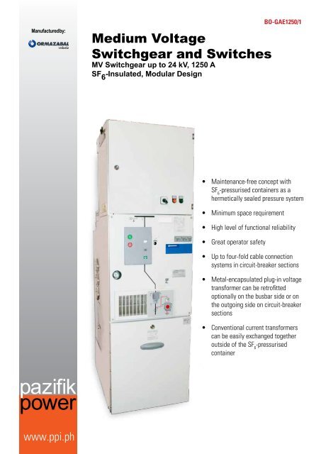
Medium Voltage<br />
<strong>Switchgear</strong> and Switches<br />
<strong>MV</strong> <strong>Switchgear</strong> up to 24 kV, 1250 A<br />
SF 6<br />
-Insulated, Modular Design<br />
BO-<strong>GAE1250</strong>/1<br />
• Maintenance-free concept with<br />
SF 6<br />
-pressurised containers as a<br />
hermetically sealed pressure system<br />
• Minimum space requirement<br />
• High level of functional reliability<br />
• Great operator safety<br />
• Up to four-fold cable connection<br />
systems in circuit-breaker sections<br />
• Metal-encapsulated plug-in voltage<br />
transformer can be retrofitted<br />
optionally on the busbar side or on<br />
the outgoing side on circuit-breaker<br />
sections<br />
• Conventional current transformers<br />
can be easily exchanged together<br />
outside of the SF 6<br />
-pressurised<br />
container<br />
pazifik<br />
power<br />
www.ppi.ph
General Information/Description<br />
Benefits of SF 6<br />
-insulated, metal-encapsulated, modular<br />
switchgear assemblies<br />
• Largely climate resistant<br />
• Maintenance-free concept with SF 6<br />
-pressurised containers as a<br />
hermetically sealed pressure system<br />
• Minimum space requirement<br />
• Comprehensive personnel protection<br />
• High level of functional reliability<br />
• Great reliability of supply<br />
• Great operator safety<br />
• Great versatility due to availability of circuit-breaker, isolator and<br />
load-break switch sections<br />
• Straightforward side-by-side fitting of sections by means of inner<br />
cone plug-in systems for the busbar connection<br />
• Up to four-fold cable connection systems in circuit-breaker sections<br />
• Metal-encapsulated plug-in voltage transformer can be retrofitted<br />
––<br />
Optionally on the busbar side or on the outgoing side on<br />
circuit-breaker sections<br />
––<br />
Optionally on the busbar side at riser panels<br />
––<br />
Optionally with isolating/earthing switch<br />
• Conventional current transformers can be easily exchanged<br />
together outside of the SF 6<br />
-pressurised container<br />
Front view<br />
Front view with open front cover<br />
Features<br />
The switchgear assemblies are type-tested, factory-built, metalencapsulated<br />
SF 6<br />
-insulated switchgear installations made up of<br />
sections.<br />
Applications<br />
Suitable for use in substations and switching stations, and also as load<br />
centers:<br />
• In electricity supply company networks, substations, main<br />
distribution substations, combined heating & power stations,<br />
cavern systems, etc.<br />
• In industrial networks with medium-voltage network infrastructure<br />
––<br />
Primary-level main distribution board/incomers/feeders,<br />
––<br />
Power stations (own production, combinal power station),<br />
––<br />
Node distribution boards,<br />
• In buildings with medium-voltage network infrastructure, e.g.<br />
in railway stations, department stores, hospitals, barracks, law<br />
courts, administrative buildings, etc.<br />
––<br />
Primary-level main distribution board/incomers/feeders,<br />
––<br />
Power stations (own production/stand-by power supply),<br />
Voltage transformer<br />
Plug-in, metal-encapsulated, single-pole voltage transformers to IEC<br />
60044-2 and VDE 0414 Part 2 are optionally flanged directly above the<br />
gas tank to the bus-sectionalizer panels with vacuum circuit-breaker<br />
-1LSV(G)-/6/, the riser sections -1HT-/6/ and the cable riser sections<br />
-1AT-/6/.<br />
They are optionally switched as busbar voltage transformers or outgoer<br />
voltage transformers.<br />
An upstream isolating or earthing switch in SF 6<br />
is optionally available<br />
(with outgoing voltage transformers it is standard). This isolating or<br />
earthing switch is operated via a drive feature that is located behind the<br />
interlocked front cover of the cable termination area. The drive feature<br />
must be equipped with a padlock.<br />
The voltage transformers can be optionally supplied with certifiable or<br />
calibrated measuring core.<br />
• In environmental projects with medium-voltage network<br />
infrastructure, e.g. in wind energy, biogas, sludge digestion,<br />
resource-recycling/-recovery plant, etc.<br />
––<br />
Primary-level main distribution boards,<br />
––<br />
Combined heating & power stations.
Current transformer<br />
In outgoing panels and bus sectionalizer panels with circuit breakers<br />
and those with load-break switches, low-voltage ring and spectaclecore<br />
current transformers to IEC 600441-1 and VDE 0414 Part 1 are laid<br />
around the extended external cone bushings.<br />
The protective and optional measuring cores are together built into a<br />
transformer block.<br />
The voltage transformers can be optionally supplied with certifiable or<br />
calibrated measuring core.<br />
The current transformers can be fitted or exchanged easily without<br />
intervention in the gas tank.<br />
In addition, it is possible to use split-core current transformers laid<br />
around the earthed cable screens of the single-core cables in the cable<br />
connection compartment or the cable duct.<br />
Technical Data<br />
<strong>Switchgear</strong> panels (rated values)<br />
Rated voltage U r<br />
7.2 kV 12 kV 17.5 kV 24 kV 1)<br />
Rated insulation level<br />
Rated power-frequency withstand voltage, AC U d<br />
kV 20 28 38 50<br />
Rated lightning impulse withstand voltage U p<br />
kV 60 75 95 125<br />
Rated frequency f r<br />
Hz 50/60 50/60 50/60 50/60<br />
Rated normal current I r<br />
For busbars A 1 250 1 250 1 250 1 250<br />
Rated short-time current I k<br />
at t k<br />
= 3s<br />
Up to<br />
kA<br />
20 20 16 16<br />
Rated peak withstand current I p<br />
Up to<br />
kA<br />
50 50 40 40<br />
Rated short-circuit making current I ma<br />
Up to<br />
kA<br />
50 50 40 40<br />
Ambient temperture T °C<br />
2), 3)<br />
-5 to +40<br />
With reduced current ratings °C Above +40<br />
Relative humidity % Maximally 95<br />
Rated filling pressure of insulating gas at 20°C and 101.3 kPa kPa 130 (30 kPa overpressure)/LSF panel 150 (50 kPa overpressure)<br />
Insulating gas SF 6<br />
Rated density of insulating gas kg/m 3 7.9<br />
Encapsulation of the HV compartment IP Hermetically welded tank, IP65<br />
Encapsulation of fuse compartment<br />
IP<br />
Single-pole arcing-free encapsulation and 3-phase metal<br />
encapsulation, IP44<br />
Encapsulation of the drive housing, relay cabinet IP IP44/IP3XD<br />
Enclosure of the cable connection compartment IP IP44<br />
Internal arc test compliant with VDE 0671, Part 200, Appendix AA and resp. kA IAC AFL 20 kA, 1 s for HV compartments<br />
IEC 62271-200<br />
kA IAC AFL 20 kA, 1 s for terminal compartments<br />
Colour of panel paint finish RAL 7 035 (light grey)<br />
Loss of service continuity category<br />
LSC 2A<br />
Partition class<br />
PM<br />
1) Higher rated voltage (25kV) on request<br />
2) Operation at lower temperatures on request<br />
3) Depending to secondary technic<br />
Standards<br />
The switchgear installation complies with the following standards and<br />
regulations:<br />
IEC 60265-1 (62271-103*)<br />
/ VDE 0670 Part 301 IEC 62271-105 / VDE 0671 Part 105<br />
(VDE 0671 Part 103*) IEC 62271-200 (60298**) / VDE 0671 Part 200<br />
IEC 60282-1 / VDE 0670 Part 4 (VDE 0670 Part 6**)<br />
IEC 62271-1 (IEC 60694**)<br />
/ VDE 0670 Part 1000<br />
(VDE 0671 Teil 1*)<br />
* = future<br />
IEC 62271-100 / VDE 0671 Part 100 ** = up to now<br />
IEC 62271-102 / VDE 0671 Part 102
Range<br />
405<br />
Outgoing feeder panel with vacuum circuit-breaker<br />
Type -1LSV-/6/<br />
Standard equipment<br />
• Vacuum circuit-breaker with stored energy operated– ON<br />
and OFF –:<br />
––<br />
Auxiliary contacts: 10 NO and 10 NC,<br />
––<br />
Tripping device – ON, OFF – DC or AC,<br />
––<br />
Signalling contact for “Starting sections charged“,<br />
––<br />
Mechanical counter,<br />
• SF 6<br />
three-position isolating and earthing switch:<br />
––<br />
Interlocked with circuit-breaker,<br />
––<br />
Manual operation,<br />
––<br />
Earthing switch with spring operated– ON and OFF–,<br />
• 3-pole SF 6<br />
-insulated busbar in the SF 6<br />
compartment,<br />
• On both sides of the SF 6<br />
-gas tank: inner cone plug-in systems<br />
for external busbar connection,<br />
• Capacitive voltage indication ledges in relay cabinet front<br />
cover,<br />
• Gas leakage indication<br />
• Pressure relief in the event of arcing directed into the cable<br />
well, panel floor open,<br />
• Lockable operators,<br />
• Arc-fault resistant cable termination compartments,<br />
• Single set of cable connection bushings for maximally<br />
double cable connection via external cone plug XLPE 2 x 1<br />
x 500 mm 2 :<br />
––<br />
One connection plug replaceable for surge arrester,<br />
• Relay- and control compartment height 600 mm.<br />
Plug-in voltage<br />
transformers<br />
Plug-in voltage<br />
transformers with<br />
isolating- and earthing<br />
feature<br />
Current transformer<br />
Maximally double cable<br />
connection<br />
Maximally fourfold<br />
cable connection with<br />
double set of bushings<br />
Surge arrester<br />
15 30 7 75 75 75 75<br />
600<br />
2000 (2300)<br />
1400 600 (900)<br />
30<br />
385<br />
575<br />
417 185<br />
770 25<br />
630A<br />
1250A<br />
Outgoing panel with vacuum circuit-breaker<br />
Type -1LSVG-/6/<br />
405<br />
Standard equipment<br />
• Vacuum circuit-breaker with stored energy operated – ON<br />
and OFF –:<br />
––<br />
Auxiliary contacts: 10 NO and 10 NC,<br />
––<br />
Tripping device – ON, OFF – DC or AC,<br />
––<br />
Signalling contact for “Starting sections charged“,<br />
––<br />
Mechanical counter,<br />
• SF 6<br />
three-position isolating and earthing switch:<br />
––<br />
Interlocked with circuit-breaker,<br />
––<br />
Manual operation,<br />
––<br />
Earthing switch with spring operated – ON and OFF –,<br />
• 3-pole SF 6<br />
-insulated busbar in the SF 6<br />
compartment,<br />
• On one side of the SF 6<br />
-gas tank: inner cone plug-in systems<br />
for external busbar connection,<br />
• Silicone insulated, controlled, external busbar to the riser<br />
panel-1HT-/6/,<br />
• Capacitive voltage indication ledges in relay cabinet front<br />
cover,<br />
• Gas leakage indication,<br />
• Pressure relief in the event of arcing directed into the cable<br />
well, panel floor open,<br />
• Lockable operators,<br />
• Arc-fault resistant cable termination compartments,<br />
• Relay- and control compartment height 600 mm.<br />
Plug-in voltage<br />
transformers<br />
Plug-in voltage<br />
transformers with<br />
isolating- and earthing<br />
feature<br />
Current transformer<br />
Capacitive voltage<br />
indication ledge<br />
2000 (2300)<br />
1400 600 (900)<br />
600 30<br />
770 25<br />
1250A
Busbar riser panel with isolating switch<br />
Type -1HT-/6/<br />
Standard equipment<br />
• SF 6<br />
three-position isolating and earthing switch:<br />
––<br />
Interlocked<br />
––<br />
Handle<br />
––<br />
Earthing switch with spring operated – ON and OFF –<br />
• 3-pole SF 6<br />
-insulated busbar in the SF 6<br />
compartment<br />
• On one side of the SF6-gas tank: inner cone plug-in<br />
systems for external busbar connection<br />
• Silicone insulated, controlled, external busbar to the<br />
bussectionalizer panel -1LSVG-/6/<br />
• Gas leakage indication<br />
• Pressure relief in the event of arcing directed into the<br />
cable well, panel floor open<br />
• Lockable operators<br />
• Arc-fault resistant terminal compartments<br />
• Relay- and control compartment height 600 mm<br />
• Intermediate frame B = 50 mm to the bus-sectionalizer<br />
panel.<br />
Plug-in voltage<br />
transformers<br />
Plug-in voltage<br />
transformers with<br />
isolating- and earthing<br />
feature<br />
Current transformer<br />
Capacitive voltage<br />
indication ledge<br />
2000 (2300)<br />
1400 600 (900)<br />
405<br />
650 30<br />
770 25<br />
1250A<br />
Cable riser panel with isolating switch<br />
Type -1AT-/6/<br />
405<br />
Standard equipment<br />
• SF 6<br />
three-position isolating and earthing switch:<br />
––<br />
Interlocked<br />
––<br />
Handle<br />
––<br />
Earthing switch with spring operated – ON and OFF –<br />
• 3-pole SF 6<br />
-insulated busbar in the SF 6<br />
compartment<br />
• On both sides of the SF 6<br />
-gas tank: inner cone plug-in<br />
systems for external busbar connection<br />
• Gas leakage indication<br />
• Pressure relief in the event of arcing directed into the<br />
cable well, panel floor open,<br />
• Lockable operators<br />
• Arc-fault resistant terminal compartments<br />
• Single set of cable connection bushings for maximally<br />
double cable connection via external cone plug XLPE 2 x<br />
1 x 500 mm 2 , (One connection plug replaceable for surge<br />
arrester)<br />
• Relay- and control compartment height 600 mm<br />
• Intermediate frame B = 50 mm to the bus-sectionalizer<br />
panel.<br />
Plug-in voltage<br />
transformers<br />
Plug-in voltage<br />
transformers with<br />
isolating- and earthing<br />
feature<br />
Maximally double cable<br />
connection<br />
Maximally fourfold cable<br />
conenction with double<br />
set of bushings<br />
15 80 7 75757575<br />
650<br />
1400 2000 (2300)<br />
600 (900)<br />
30<br />
385<br />
575<br />
417 185<br />
770 25<br />
630A<br />
1250A
Outgoing feeder panel with SF 6<br />
circuit-breaker based on<br />
arc quenching coil Type -1LSF-/6/<br />
Standard equipment<br />
• SF 6<br />
three-position circuit-breaker and earthing switch:<br />
––<br />
Including interlock,<br />
––<br />
Handle,<br />
––<br />
Circuit-breaker with spring operated – ON, and stored<br />
energy operated – OFF,<br />
––<br />
Earthing switch with spring operated – ON and OFF –,<br />
• Manual Emergency-Stop push-button,<br />
• 3-pole SF 6<br />
insulated busbar in the SF 6<br />
compartment,<br />
• On both sides of the SF 6<br />
gas tank: inner cone plug-in systems<br />
for external busbar connections,<br />
• Capacitive voltage indication ledges,<br />
• Gas leakage indication,<br />
• Pressure relief in the event of arcing directed into the cable<br />
well, panel floor open,<br />
• Lockable operators,<br />
• Arc-fault resistant cable termination compartments,<br />
• Single set of cable connection bushings for maximally<br />
double cable connection via external cone plug XLPE 2 x<br />
1 x 500 mm 2 , (One connection plug replaceable for surge<br />
arrester),<br />
• Relay- and control compartment, height 600 mm.<br />
Current transformer<br />
Maximally double<br />
cable connection<br />
Surge arrester<br />
15 150<br />
250<br />
600<br />
2000 (2300)<br />
210 600 (900)<br />
500 690<br />
357<br />
1035<br />
540<br />
730 25<br />
630A<br />
Cable panel with load-break switch and vertically<br />
arranged bushings Type -1K-/4/<br />
Standard equipment<br />
• SF 6<br />
three-position load-break and earthing switch:<br />
––<br />
Including interlock,<br />
––<br />
Manual operation,<br />
––<br />
Load-break and earthing switches with spring-operated<br />
– ON and OFF –,<br />
• 3-pole SF 6<br />
-insulated busbar in the SF 6<br />
compartment,<br />
• On both sides of the SF 6<br />
-gas tank: inner cone plug-in<br />
systems for external busbar connection,<br />
• Capacitive voltage indication ledges,<br />
• Gas leakage indication<br />
• Pressure relief in the event of arcing directed into the cable<br />
well, panel floor open,<br />
• Lockable operators,<br />
• Arc-fault resistant cable termination compartments,<br />
• Single set of cable connection bushings for maximally<br />
double cable connection via external cone plug XLPE 2 x<br />
1 x 500 mm 2 , (One connection plug replaceable for surge<br />
arrester),<br />
• Relay- and control compartment height 600 mm.<br />
Maximally double<br />
cable connection<br />
Surge arrester<br />
8686<br />
200<br />
400<br />
2000 (2300)<br />
500 690 210 600 (900)<br />
887<br />
120 120<br />
35<br />
357<br />
185 185<br />
887<br />
87<br />
470<br />
665 25<br />
630A
Cable panel with load-break switch and horizontally<br />
arranged bushings Type -1K-/6/<br />
Standard equipment<br />
• SF 6<br />
three-position load-break and earthing switch:<br />
––<br />
Including interlock,<br />
––<br />
Handle,<br />
––<br />
Load-break and earthing switches with springoperated<br />
– ON and OFF –,<br />
––<br />
3-pole SF 6<br />
-insulated busbar in the SF 6<br />
compartment,<br />
• On both sides of the SF 6<br />
gas tank: inner cone plug-in<br />
systems for external busbar connection,<br />
• Capacitive voltage indication ledges,<br />
• Gas leakage indication<br />
• Pressure relief in the event of arcing directed into the<br />
cable well, panel floor open,<br />
• Lockable operators,<br />
• Arc-fault resistant cable termination compartments,<br />
• Single set of cable connection bushings for maximally<br />
double cable connection via external cone plug XLPE 2 x<br />
1 x 500 mm 2 , (One connection plug replaceable for surge<br />
arrester),<br />
• Relay- and control compartment height 600 mm.<br />
Maximally double<br />
cable connection<br />
Surge arrester<br />
150 150<br />
300<br />
600<br />
2000 (2300)<br />
210 600 (900)<br />
500 690<br />
35<br />
357<br />
470<br />
665<br />
630A<br />
1035<br />
25<br />
Transformer feeder panel with fused load-break switch<br />
Type -1TS-/4/<br />
Standard equipment<br />
• SF 6<br />
three-position load-break and earthing switch:<br />
––<br />
Including interlock,<br />
––<br />
Manual operation,<br />
––<br />
Load-break switch with spring operated – ON, and<br />
stored energy operated – OFF,<br />
––<br />
Earthing switch with spring operated – ON and OFF –,<br />
• Indication of tripped fuse,<br />
• 3-pole SF 6<br />
-insulated busbar in the SF 6<br />
compartment,<br />
• On both sides of the SF 6<br />
-gas tank: inner cone plug-in<br />
systems for external busbar connection,<br />
• 3-phase plug-on fuse arrangement,<br />
• Earthing switch in SF 6<br />
downstream of the HRC fuse,<br />
• 3-pole slip-on type cable termination for transformer<br />
cables, maximally XLPE 1 x 240 mm 2 ,<br />
• Capacitive voltage indication ledges upstream and<br />
downstream of the fuse,<br />
• Gas leakage indication,<br />
• Pressure relief in the event of arcing directed into the cable<br />
well, panel floor open,<br />
• Lockable operators,<br />
• Arc-fault resistant terminal compartment,<br />
• Relay- and control compartment, height 600 mm.<br />
200<br />
126 126<br />
400<br />
2000 (2300)<br />
210 600 (900)<br />
500 690<br />
35<br />
357<br />
537<br />
570<br />
480<br />
665 25
1<br />
1 0<br />
1<br />
1 0<br />
Busbar earthing panel with earthing switch<br />
Type -1E-/4/<br />
Standard equipment<br />
• SF 6<br />
-insulated 3-pole earthing switch for busbar earthing:<br />
––<br />
Earthing function as three-position switch,<br />
––<br />
Manual operation,<br />
––<br />
Spring operated – ON and OFF –,<br />
• 3-pole SF 6<br />
-insulated busbar in the SF6 compartment,<br />
• On both sides of the SF 6<br />
-gas tank: inner cone plug-in systems for<br />
external busbar connection,<br />
• Earthed short-circuit bridge via vertical, frontal external cone<br />
bushing arrangement,<br />
• Gas leakage indication,<br />
• Pressure relief in the event of arcing directed into the cable well,<br />
panel floor open,<br />
• Lockable operators,<br />
• Arc-fault resistant terminal compartments,<br />
• Relay - and control compartment, height 600 mm.<br />
2000 (2300)<br />
690 210 600 (900)<br />
500<br />
400 35<br />
665 25<br />
357<br />
Metering panel with busbar riser<br />
Type -1M1-/12,5/<br />
Standard equipment<br />
• 3-pole busbar for bus-sectionalizer circuit-breaker panel -1LSVG-,<br />
• On one side of the metering panel: inner cone plug-in systems for<br />
external busbar connections,<br />
• Compact insulators - current- and/or voltage transformers, DIN<br />
42660 part 8 resp. 9, IEC 600441,<br />
• Arc-fault resistant terminal compartments,<br />
• Relay - and control compartment, height 600 mm.<br />
3 6 0<br />
2 0 0 0 ( 2 3 0 0 )<br />
1 4 00 6 0 0 ( 9 ) 0 0<br />
4 9 5<br />
Voltage transformer<br />
Current transformer<br />
1 0 5 0 2 0 0<br />
7 7 0 2 5
Front panel<br />
Front panel with:<br />
• Mimic diagram<br />
• Switch position indication<br />
• Operator surface for the actuators<br />
• Capacitive voltage indicators<br />
• Gas leakage indication<br />
• Short-circuit indicators<br />
• Padlocking facility<br />
• Drive sealed against dust, sand and insects<br />
• Housing IP44<br />
Pressure switch/ Density monitor<br />
Each gas tank can be fitted with a pressure switch and/or density<br />
monitor for remote monitoring (auxiliary contact). The lower switching<br />
point corresponds to the crossover point to the red measuring range<br />
on the gas leakage indication. The density monitor can be optionally<br />
equipped with alarm and tripping indicator auxiliary contacts.<br />
Phase sequence indication<br />
Voltage display and Testing<br />
Type -1K-<br />
Type -1TS-<br />
Each system is equipped with the necessary three-phase capacitive<br />
voltage detection system, Type KSO, for voltage testing to VDE 0682<br />
Part 415 and IEC 61243-5 with HR system (other systems on request).<br />
This enables the absence of voltage in individual phases to be verified<br />
by inserting the voltage indication plugs into the corresponding pairs<br />
of sockets. The voltage detection system circuitry is designed for<br />
rated operational voltages of 10, 15 and 20 kV. The minimum and<br />
maximum values of the Standard for these voltage ranges are adhered<br />
to in the standard system. It is not necessary therefore to adjust them<br />
again when changing the rated operational voltage within this range.<br />
Rated operational voltage 6 kV can be implemented in a special version.<br />
The live contact sockets are touch-protected.<br />
Voltage detection system in sealed version<br />
Type -1LSV-<br />
Voltage indication plug<br />
(Picture shows Horstmann device)<br />
Gas leakage indication<br />
Each gas tank has a pressure display for verification of the SF<br />
overpressure within, allowing its functional safety to be inspected.<br />
The following devices may be used:<br />
Pfisterer<br />
Horstmann<br />
Type DSA-2<br />
Type HMO-ST-1<br />
Indication devices are also suitable for continuous duty.<br />
Meaning of the indication:<br />
Green = operating pressure OK<br />
Red = operating pressure not OK.
Single-line diagram of a voltage indicator<br />
Voltage indication via capacitive voltage divider, HR system.<br />
Voltage indication plugged in.<br />
C1 Capacitor integrated in the bushings.<br />
C2 Capacitance of the connecting cables and the voltage indication<br />
device to earth.<br />
U LE<br />
= U N<br />
/√3 During rated operation in a three-phase system.<br />
U 2<br />
= UA = Voltage at the capacitive interface of the system or at the<br />
voltage indication device.<br />
Other types and products on demand.<br />
ALPHA E<br />
ALPHA automatic<br />
DELTA M<br />
DELTA E<br />
EKA-3<br />
EKA 3/1<br />
GAMMA 4.0<br />
Opto<br />
Sigma<br />
T connection fittings<br />
T connection fittings are to be used as the operator thinks fit.<br />
Connectable to bushings to DIN EN 50181 connection type C (630A)<br />
with external cone and bolt contact (M16).<br />
With non-controlled systems, the manufacturer’s mounting instructions<br />
are to be adhered to implicitly.<br />
Accessories for the system<br />
Phase Sequence Indication by Interface Tester<br />
(Picture shows Horstmann device, Type ORION 3.0)<br />
Operating levers<br />
Figure 13<br />
The following devices may be used:<br />
Make<br />
Phase sequence<br />
indication<br />
Interface tester<br />
Horstmann - H-OM measuring<br />
module with Fluke<br />
ammeter Type 87 or<br />
matrix Type Mx55 (II<br />
to IV)<br />
Horstmann Type: Orion Type: Orion<br />
Pfisterer Type: EPV Type: Euro test-HO<br />
Short-circuit/Earth-fault indicator.<br />
Operating levers, keys for fasteners<br />
Operating lever (optional) for the load-break switch<br />
actuating shaft with motor operator (for manual switching<br />
e.g. in case of loss of supply voltage).<br />
Operating lever for the earthing switch (optional red shaft).<br />
Operating lever for the load-break switch (optional plain<br />
shaft).<br />
Charging handle for vacuum circuit-breakers<br />
Key for the fastener on the front cover (controls the antireverse<br />
interlock).<br />
Cable clamps<br />
Size I<br />
Clamping range 26 to 55 mm for cables, such as<br />
• 12 kV: 35 mm 2 240 mm 2<br />
• 24 kV: 25 mm 2 185 mm 2<br />
All ring cable panels can be equipped either with a 3-phase shortcircuit<br />
or earth-fault indicator.<br />
Size II<br />
Clamping range 36 to 52 mm for cables, such as<br />
Manufacturer<br />
Horstmann<br />
Type<br />
ALPHA M<br />
• 12kV: 300 mm 2<br />
• 24kV: 240 mm 2<br />
The precise cable diameter must be compared with the clamping<br />
range.
Coupling and bolt connection kits<br />
Busbar coupling kit with double gasket<br />
For panel version for pressure relief via rear towards the top (panel<br />
for floor bulkhead).<br />
Pressure relief via rear<br />
absorber channel towards<br />
the top<br />
Shown: 1 phase<br />
Busbar end cover with single gasket<br />
Shown: 1 phase<br />
100<br />
ca. 1150<br />
Parts for bolt connection of panels<br />
<strong>Switchgear</strong> related pressure calculations can be enquired as part of services.<br />
Protection technology<br />
Shown: 1 set<br />
Arc fault protection, panel installation<br />
For standard panel version with pressure relief into the cable well<br />
or cable duct.<br />
All commercially available protection relays can be installed in<br />
the switchgear for the LSV circuit breaker panels and LSF circuit<br />
breaker panels.<br />
The variants range from transformer-operated protection relays to<br />
combined protection and control systems.<br />
Low energy trips 0.5 VA and 0.1 VA are available for the transformeroperated<br />
relays.<br />
In this context special relay-transformer combinations are tested.<br />
Common protocols and interfaces, e.g. Profibus DP, Modbus, IEC<br />
60870-5-103, IEC 60870-5-101 and IEC 61850 can be provided with<br />
related relays.<br />
Installation is in low-voltage compartment / relay niche.<br />
Optionally, the protection relay can also be installed in the related<br />
cover.<br />
Pressure relief into the cable well or<br />
cable duct<br />
It is also possible to configure the parameters for the protection<br />
relay in accordance with customer requirements.<br />
A few commercially available protection relays as examples:<br />
100<br />
600
http://www.ppi.ph/dlfiles/orgae.pdf