Step by step - 06-09-2016

You also want an ePaper? Increase the reach of your titles
YUMPU automatically turns print PDFs into web optimized ePapers that Google loves.
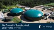
Qila Anaerobic Digestion plant<br />
<strong>Step</strong> <strong>by</strong> <strong>step</strong> process
1 - Feedstock is taken from the clamps<br />
and loaded into the feeder<br />
Feedstock is gathered and delivered to the Anaerobic Digestion plant. It is<br />
transported in pre-weighed trucks and driven onto weigh bridge, so that<br />
each ton of feedstock is measured into the plant. The feedstock is then<br />
stored in holding clamps, ready to be inserted into the plant.<br />
The plant operator will then move the feedstock into hoppers, which<br />
holds and weighs the amount added.<br />
The plant will usually require 40,000 - 46,000 tonnes of feedstock each<br />
year, this will be approximately 60 - 120 tonnes time it is fed, depending<br />
on the density of material being added. Feeding is required every 1-3<br />
days.<br />
The feeder mixes and grinds the feedstock into small pieces, using a<br />
series of screw conveyors, it then transfers the solid matter towards the<br />
Energy Jet and Rotacut units.
2 - The feedstock is moved to the Energy Jet<br />
and RotaCut units<br />
The EnergyJet unit is an efficient solution, which continually feeds the digester with well-mashed<br />
feedstock which has been mixed with liquid Digestate (which is circulated from the storage tank.)<br />
The process of mixing, mashing and masticating reduces the time needed in the tanks and<br />
increases the gas yield of the plant. To maintain the correct bacterial population in the Turbo Tank,<br />
the substrate must have a dry matter content of 11%.<br />
Initially, the feedstock is moved along a conveyor to a screw, which removes any extra moisture and<br />
forms a dry plug. A high flow of liquid digestate, combined with a rotating screw blade breaks up<br />
the plug to form a mashed liquid suspension. This is further blended with a screw which enables<br />
liquid feedstock feeding into the Turbo Tank. The previously extracted moisture is collected and fed<br />
into the system, ensuring that no nutrients are wasted.<br />
The RotaCut macerator unit, further breaks up the material before it is pumped into the Turbo<br />
Tank. At the same time, it separates foreign bodies, such as stones and pieces of metal, preventing<br />
them from damaging parts of the system downstream and from collecting in the digester.
3 - The liquid feedstock is moved to the<br />
Turbo Tank<br />
The liquid feedstock suspension is pumped into the Turbo Tank, via the pump room. The first stage<br />
of the AD process, Hydrolysis, occurs in this tank as the matter is broken down <strong>by</strong> the bacteria. The<br />
tank is maintained at 50 -55 °C, using hot water circulated in steel coils around the inner<br />
circumference of the tank. The water is heated to temperature <strong>by</strong> harnessing the heat produced in<br />
the Combined Heat and Power Engine (CHP), as it burns some of the biogas that is produced on<br />
site.<br />
The feedstock in the Turbo Tank is broken down <strong>by</strong> the microorganisms in approximately 2–3 days.<br />
During the hydrolysis phase, the gas that is produced, contains a high percentage of Carbon<br />
Dioxide.<br />
The tank is made of concrete which is cast in-situ, this method provides a stronger more durable<br />
tanks than those constructed from concrete panels or stainless steel, and therefore offers a more<br />
robust design. The tank is then insulated to retain the heat and covered with aluminium cladding.<br />
This tank has a flat gas-tight concrete roof and the net volume of the tank is 1,407m 3 .
The Qila design uses three mixers in the Turbo Tank. These high quality<br />
mixers have a 5.75m long shaft and 840mm propeller and are designed to<br />
prevent the development of settled and floating layers in the tank. The<br />
mixers mounted, at different heights, which enable mixing at all levels of<br />
the tank. This ensures a homogenised substrate and good circulation of<br />
the liquid thus maximising gas production. Efficient mixing, which is<br />
controlled via the control panel, avoids solidification and stratification of<br />
the substrate in the tank.<br />
This unit offers a powerful mixing technology, with low-noise transmission<br />
<strong>by</strong> means of a toothed geared belt drive. The agitator mounting has<br />
anti-vibration bearings and the drive shaft has multiple ball bearings<br />
running in an oil bath. It offers a user friendly hydraulic adjustment system.<br />
The mixers gear boxes are mounted externally to enable access for<br />
maintenance.<br />
The movement of the liquid feedstock and substrate between the various<br />
tanks on the plant is via the pump room where the lobe pumps and<br />
controls are located. If the Turbo tank is unavailable, for example down for<br />
maintenance, there is an option to <strong>by</strong>pass the tank and move any liquid<br />
feedstock directly to the main digester.
4 - The liquid feedstock is then transferred to<br />
the digester tank – main biogas production<br />
After 2-3 days, the liquid feedstock is moved, via the pump room, to the digester tank. There the<br />
methanogenic bacteria continue to break down the organic matter and produces the majority of the biogas.<br />
The gas then rises and collects at to the top of the digester and is then moved to the CHP engine, the<br />
upgrader unit or into the final storage tanks. The digestate is moved to the separator unit, where it is<br />
separated into its liquid and solid forms.<br />
The main digester tank is maintained at 41-44 o C using heating coils to circulate hot water around the tank.<br />
The Turbo Tank heat is taken from the CHP engine which burns biogas produced <strong>by</strong> the plant. The retention<br />
time in the main digester tank it about 15-20 days. This gives an average retention time of processing<br />
feedstock through both tanks of 18.3 days. The net volume of the digester tank is in the region of 7,200 m 3 .<br />
The digester tank has walls made of concrete, which is cast in-situ, insulated and then covered with cladding.<br />
The tanks have a double membrane dome roof. The inner shell is the integrated gas storage and the outer<br />
membrane is a durable weather protection foil. The tanks are also interconnected with pipes, so gas<br />
pressures can be monitored and biogas moved around the plant. The biogas is also stored in the storage<br />
tanks. The pressure of the gas is monitored on all the domes and if this becomes too high there is a hydraulic<br />
pressure release valve to release biogas, if needed.
The digester tank has four mixers. The variable angle of the mixers<br />
is easily adjusted <strong>by</strong> a hydraulic unit, so the optimum positioning of<br />
the mixers can be controlled <strong>by</strong> the operators who set the mixing<br />
pattern, which will depend on the exact characteristics of the<br />
substrate within the tank. The mixers have a 4.5m shaft and a<br />
1600mm propeller. These are highly efficient mixers, even when<br />
the dry substance content if high. The mixing provided is strong<br />
and slow, but also gentle which is well suited to operating in the<br />
digester tank.<br />
As the gear mechanism is outside the tank, it allows for easy maintenance, as no electrical components are<br />
situated within the tank. The mixer is mounted with anti-vibration bearings which are fixed to an instillation<br />
bracket. This robust gear unit has low noise during operation. The drive shaft has multiple bearings and an oil-bath<br />
lubrication.<br />
The biogas produced is mainly methane, (50% and 65%), Carbon dioxide (48%-33%) some water, Hydrogen<br />
sulphide and some other impurities in small quantities.<br />
One of the impurities in the biogas is Hydrogen Sulphide (H 2 S), biological desulphurisation which removes this can<br />
be facilitated <strong>by</strong> injection of small amounts of oxygen, or air, into the tanks. This occurs as the oxygen encourages<br />
the growth of a certain type of bacteria, called thiobacilli, which occur on the surface of the digestate and as they<br />
grow and use the H 2 S in the biogas and leave a yellow clusters of sulphur on surface of the digestate. This process<br />
can also be performed in the storage tanks.
5 - Biogas is moved to the upgrader, where<br />
it is cleaned to generate Biomethane<br />
Biogas is moved from where is stored in the domes of the digester and storage tanks, to the<br />
upgrader unit. In the upgrader, the gas is cleaned <strong>by</strong> removing the CO 2 and other impurities to<br />
produce biomethane which is suitable to be injected into the national gas grid.<br />
Biogas usually contains around 60% methane, 40% CO 2 , a small amount of water, hydrogen sulphide<br />
and a few other impurities. In order to inject the gas into the national grid, the upgrader unit must<br />
remove all the moisture, hydrogen sulphide and other impurities and most of the CO 2 . The<br />
biomethane should contain about 97-98% methane to be entered into the grid.<br />
The Qila design uses a high quality membrane technology from Pentair Haffmans to separate the<br />
methane from the the CO 2 and other gasses. The gasses have different molecular size and varying<br />
solubility thus permeate the membrane to differing degrees. The membrane acts as a molecular<br />
sieve, letting some gasses pass through easily, such as Co 2 and water vapour whilst the methane<br />
(CH 4 ) does not pass through the membrane. The gas that does not pass though the membrane<br />
becomes enriched in methane.
The technology is an efficient and cost effective<br />
method to upgrade biogas and requires a low energy<br />
input compared to some alternatives.<br />
As the gas enters the upgrader it is pressurised and the<br />
methane content of the gas is analysed. The gas is<br />
then scrubbed to remove water soluble impurities and<br />
chilled. Active carbon filters are used to remove<br />
Hydrogen Sulphide (H 2 S) <strong>by</strong> a process called<br />
adsorption. The removal of the H 2 S protects the plant<br />
and the membranes. The pressurised gas is then<br />
heated and passed through the biogas separation<br />
membrane unit.<br />
The biogas separation membrane unit is contained<br />
within stainless steel housing. The membranes split<br />
the gas into CO 2 and a methane rich gas.<br />
If there is a build-up of gas over and above the<br />
amount that can be safely stored or processed <strong>by</strong> the<br />
upgrader and the CHP unit, this can be securely<br />
disposed off via the flare.
6 - Biomethane is moved to the Grid<br />
Entry unit<br />
Once the gas has upgraded to about 97 - 98% methane, the biogas moves<br />
to the grid entry unit. This equipment monitors the quality of the gas<br />
and ensures that it conforms to the specifications and pressure of the gas<br />
required in the grid.<br />
Natural gas is made up of several gases, some of which have a higher<br />
calorific value than methane. To bring the biomethane up to the same<br />
energy content, approximately 4% of propane must be added at the point<br />
of injection. An odorant must also be added for health and safety reasons<br />
– as this gives the gas a smell and should it escape it can be detected. The<br />
pressure of the gas must also match that of the pipeline in which it will<br />
be injected.<br />
Prior to injection, the Grid Entry Unit adds propane (approximately 4%)<br />
to the biogas so that it matches the calorific value of the gas in the<br />
national grid. The Renewable Heat Incentive (RHI) subsidy is payable on<br />
all eligible biomethane injected.
7 - Biomethane enters the National Gas<br />
Grid and reaches the end user<br />
Once the gas is in the grid, it is easy to arrange to sell the gas to<br />
residential and industrial customers.<br />
As well as, the benefits to the farmer, using biogas to displace gas<br />
from fossil sources reduces levels of greenhouse gases in the<br />
atmosphere. This is because all the CO2 released on combusting<br />
the biogas has recently been absorbed from the atmosphere,<br />
unlike for the fossil fuels.<br />
Upgrading biogas to biomethane maximises these benefits, as far<br />
less of the energy is wasted compared to using it to generate<br />
electricity or power vehicles.
8 – Biogas is used to generate electricity using<br />
a Combined Heat & Power (CHP) unit<br />
Some of the biogas, which is stored in the main digester and the storage tanks, is moved to a Combined and<br />
Heat Power (CHP) unit, which powers an alternator and generates electricity. The electricity is used to power<br />
the plant and additional electricity is sold to the power grid. Annually a 499kw CHP unit is expected to<br />
generate about 4,000,000 kWh/a if it runs at 92% availability which enables the plant to run on self-generated<br />
power.<br />
During the process, heat is also produced which is harnessed to heat water circulated to the Turbo Tank and<br />
used to keep the digester tank at the required temperatures. Other uses for the heat produced are to dry the<br />
solid digestate or to heat any buildings. The CHP unit is expected to produce about 4,700,000 kWh of thermal<br />
energy each year which is used within in the plant. There are subsidies for the production of the electricity in a<br />
CHP unit and using the heat that is produced.<br />
Before the biogas is moved to the CHP unit, it is cooled to condense and remove any moisture content which is<br />
in the gas. It is then reheated, to avoid further condensation and passed through a carbon filter to remove any<br />
remaining H 2 S. The gas is then pressurised with a biogas blower and enters the CHP unit.
9 - Digestate is removed from the main<br />
digester tank, separated and returned to<br />
farm land<br />
The process of converting feedstock into biogas leaves a residue - the digestate. This is then passed through a screw press which separates the<br />
solid fibrous fraction from the liquid. The liquid digestate is piped to the storage tanks and the solid matter is collected under the screw press<br />
in a dedicated skip below the separator – both are stored until they can be spread onto farm land.<br />
The liquid digestate is transferred to the storage tanks via the pump room. The combined storage capacity of the tanks must be able to hold<br />
the liquid digestate, and any contaminated rainwater, produced during for 6 months of operation this is estimated to be 14,500 m 3 . This is<br />
important as there are times of the year when there are restrictions to liquid digestate spreading and the plant must be able to hold the<br />
digestate produced over this time.<br />
The storage tank has a gas tight dome and 3 mixers are installed with keep the digestate moving. There continues to be some biogas<br />
production from the storage tank, and as there is controlled gas flow between the tanks and parts of the plant, the biogas produced is moved<br />
to the upgrader or the CHP engine. As with the main digester oxygen is also introduced to into the gas storage to facilitate the biological<br />
removal of the hydrogen sulphide.<br />
The digestate is a nutrient-rich <strong>by</strong>-product of the AD process. It contains the leftover organic material and any dead microorganisms. It is<br />
separated into solid and liquid fractions, both of which can be used as a biofertiliser. As a general rule the amount of digestate produced will be<br />
90% of the feed stock. Of this digestate, about 25% is solid and the rest is in liquid form<br />
The digestate can have a significant fertilizer value and also assists in returning organic matter to the soil. It should be applied to the land<br />
according to a nutrient management plan. Using digestate in place of synthetic fertilisers saves energy, cuts consumption of fossil fuels and<br />
reduces farm expenditure and management costs. This is an often underestimated benefit of an AD plant. Significant improvements in both<br />
yield and crop quality are possible.<br />
The typical values for the digestate are:<br />
Nitrogen: 2.3-4.2 kg/tonne Potassium: 1.3-5.2 kg/tonne Phosphorus 0.2 1.5 kg/tonne
10 - The Qila control panel<br />
Qila plants are managed <strong>by</strong> a bespoke control system. This provides central engineering, operation and<br />
monitoring of field technology, as well as, a motor control centre and switchgear with one integrated<br />
view of the production and electrical processes. It is user friendly and intuitive design allows<br />
multifunctional controls and reporting.<br />
Remote access login in allows off site monitoring of the site when required and a digital cloud-based<br />
monitoring control system can be operated from smart phones and tablets whilst on the move. As the<br />
system is designed <strong>by</strong> Qila, it can be made to cater for the individual needs of each plant.<br />
An integrated view of the production and electrical processes is provided as the control centre monitors<br />
the system. This provides:<br />
• Increasing plant availability and reducing maintenance requirements through integrated asset<br />
management functionalities and revolutionary online diagnostics.<br />
• Low installation costs through the use of bus technology allows you to add devices quickly and easily<br />
• Lower engineering costs due to comprehensive software tools<br />
• Reduced commissioning time through flexible automation solutions<br />
• Increasing transparency through automatic archiving and reporting of process and plant information
How we can help you?<br />
Qila Energy is a British biogas engineering company building CHP and<br />
biomethane gas to grid AD plants across the UK.<br />
No matter what stage of your project, our team of UK based engineers can<br />
help you throughout the throughout the whole process, from initial design,<br />
construction and 24/7 ongoing maintenance. We can help you with:<br />
• Planning permission<br />
• Environmental Permitting Regulations<br />
• Design of the AD plant<br />
• Construction and Construction (Design and Management) Regulations<br />
(CDM)<br />
• Feedstock planning<br />
• Grid connection<br />
• FIT & RHI payments<br />
• OFGEM sustainability
Qila Energy | Royal Institution of Great Britain | 21 Albemarle Street | London | W1S 4BS<br />
020 3603 3016 | info@qilaenergy.com | qilaenergy.com