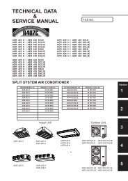
TECHNICAL DATA & SERVICE MANUAL
TECHNICAL DATA & SERVICE MANUAL
TECHNICAL DATA & SERVICE MANUAL

Create successful ePaper yourself
Turn your PDF publications into a flip-book with our unique Google optimized e-Paper software.
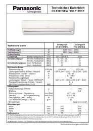
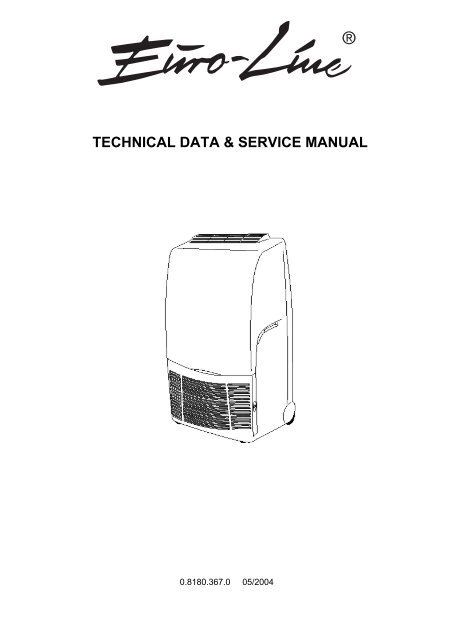
<strong>TECHNICAL</strong> <strong>DATA</strong> & <strong>SERVICE</strong> <strong>MANUAL</strong><br />
0.8180.367.0 05/2004<br />
®
Page<br />
1. SPECIFICATIONS 3<br />
1-1 Unit Specifications 3<br />
1-2 Major Component Specifications 4<br />
2. DIMENSIONAL <strong>DATA</strong> 6<br />
2-1 Unit Dimensions 6<br />
3. ELECTRICAL <strong>DATA</strong> 7<br />
3-1 Electric Wiring Diagram 7<br />
4. REFRIGERANT FLOW <strong>DATA</strong> 8<br />
4-1 Refrigerant Flow Diagram 8<br />
5. FUNCTION 9<br />
5-1 Room Temperature Control 9<br />
5-2 Heat Exchanger Frosting Prevention 9<br />
5-3 Dry Operation (Dehumidification) 10<br />
6. PERFORMANCE <strong>DATA</strong> 11<br />
6-1 Performance Chart 11<br />
7. TROUBLESHOOTING 12<br />
7-1 The unit does not work 12<br />
7-2 Electrical circuit interrupted after "ON" button is pressed 12<br />
7-3 Electrical circuit interrupted 3 minutes after "ON" button is pressed 13<br />
7-4 Fan motor does not work while "ON" button is pressed 13<br />
7-5 Fan works at one speed only 14<br />
7-6 Poor cooling 14<br />
7-7 Fan motor works normally but the compressor does not operate 15<br />
2
1. SPECIFICATIONS<br />
1-1 Unit Specifications<br />
Power source<br />
Voltage rating<br />
Performance<br />
Capacity (1) (1) W<br />
Efficiency (2) (2) W/W<br />
Air flow rate (evaporator) Hi/Lo m³/h<br />
Air flow rate (condenser) Hi/Lo m³/h<br />
Moisture removal l/h<br />
Moisture removal (3) l/24h<br />
Moisture removal (4) l/24h<br />
Electrical ratings<br />
Available voltage range V<br />
Power input W<br />
Running amperes A<br />
Power input (3) W<br />
Running amperes (3) A<br />
Power input (4) W<br />
Running amperes (4) A<br />
Compressor locked rotor A<br />
Features<br />
Controls/Temperature controls<br />
Control unit<br />
Timer<br />
Fan speed<br />
Air Filter<br />
Operation sound Lp (5) Hi/Lo dB(A)<br />
Compressor<br />
Refrigerant / Amount charged at shipment g<br />
Refrigerant control<br />
Water tank capacity liters<br />
Flexible exhaust tube I.D. mm<br />
extended length m<br />
Hole in the window mm<br />
Electric cable with plug length m<br />
Dimensions & Weight<br />
Unit dimensions Height mm<br />
Width mm<br />
Depth mm<br />
Package dimensions Height mm<br />
Width mm<br />
Depth mm<br />
Volume m³<br />
Weight Net kg<br />
Shipping kg<br />
Data subject to change without notice<br />
Rating conditions<br />
(1) Cooling indoor air temperature: 27 °C d.b. , 19 °C w.b<br />
(2) Cooling indoor air temperature: 35 °C d.b. , 24 °C w.b<br />
220 - 240 V ~ 50 Hz<br />
230 V<br />
COOLING DEHUMIDIFICATION<br />
WITH AIR EXHAUSTING TUBE WITHOUT AIR EXHAUSTING TUBE<br />
2100<br />
-<br />
2,75<br />
310 / 260 260<br />
290 / 240 240<br />
1 -<br />
- 23<br />
-<br />
42<br />
198 - 264<br />
700 -<br />
3,3<br />
-<br />
-<br />
710<br />
- 3,2<br />
-<br />
770<br />
- 3,5<br />
13<br />
Microprocessor / I.C. Thermostat<br />
Switches on the unit<br />
-<br />
2 1<br />
Washable<br />
55 / 51 51<br />
Rotary (hermetic)<br />
R410A / 470<br />
Capillary tube<br />
~ 3,3<br />
115<br />
1<br />
138<br />
2,9<br />
870<br />
476<br />
390<br />
1110<br />
577<br />
483<br />
0,31<br />
32<br />
41<br />
(3) Dehumidification indoor air temperature: 27 °C d.b. , 21 °C w.b , 60% u.r.<br />
(4) Dehumidification indoor air temperature: 30 °C d.b. , 27 °C w.b , 80% u.r.<br />
(5) Reference data: room size 100 m 3 , reverberation time 0,5 s , distance 2 m<br />
Operating limits maximum minimum<br />
Indoor air temperature Cooling 35 °C d.b. , 24 °C w.b 15 °C d.b. , 12 °C w.b<br />
Dehumidification 35 °C d.b. , 28 °C w.b 10 °C d.b. , 6,5 °C w.b<br />
3
1-2 Major Component Specifications<br />
Controller PCB (CE) RY2<br />
Controls Electronic<br />
setting °C 15 ± 1,5 ÷ 31 ± 2<br />
differential °C 0,9 ± 0,2<br />
Starting delay time 3 min ± 10 s<br />
ON / OFF<br />
Function selection and indicator lamp<br />
COOLING / FAN<br />
HIGH / LOW FAN<br />
ALARM LAMP<br />
capacity VA 1,5<br />
primary V 220<br />
Trasformer<br />
secondary V 10,5<br />
coil resistance primary (20°C) Ω 2754 ± 10%<br />
coil resistance secondary (20°C) Ω 17,1 ± 10%<br />
Thermistor (coil sensor) (TH1) NTC<br />
open °C 1 ± 1<br />
close °C 6 ± 1<br />
-20 °C: 5846 ± 5% ; 20 °C: 604 ± 5%<br />
Resistance<br />
Ω<br />
-10 °C: 3159 ± 5% ; 30 °C: 368 ± 5%<br />
0 °C: 1766 ± 5% ; 40 °C: 230 ± 5%<br />
10 °C: 1018 ± 5% ; 50 °C: 147 ± 5%<br />
Thermistor (room sensor) (TH2) NTC<br />
10 °C: 1018 ± 5% ; 30 °C: 368 ± 5%<br />
Resistance Ω<br />
15 °C: 781 ± 5% ; 35 °C: 290 ± 5%<br />
20 °C: 604 ± 5% ; 40 °C: 230 ± 5%<br />
25 °C: 470 ± 5% ; 50 °C: 147 ± 5%<br />
Fan & Fan Motor (FM) M01974<br />
Type Centrifugal blower<br />
Q'ty ……. Dia. and lenght mm 1…. Ø 170 / L 156<br />
No. Of poles 4<br />
Rpm Hi / Lo speed 1275 / 1058 with flexible exhaust tube retracted<br />
Power input (230 V) W (Hi / Lo) 109 / 80<br />
GREY-WHITE: 87,3 ÷ 101<br />
WHITE-VIOLET: 36,2 ÷ 41,6<br />
Coil resistance (25°C ) Ω<br />
VIOLET-YELLOW: 22,8 ÷ 26,3<br />
YELLOW-PINK: 22,8 ÷ 26,3<br />
GREY-BROWN: 51,9 ÷ 59,6<br />
type Thermostat<br />
Safety devices<br />
operating temp.<br />
open<br />
close<br />
°C<br />
°C<br />
(C1)<br />
150 ± 10<br />
Automatic<br />
Run capacitor<br />
µF 3<br />
VAC 450<br />
Float microswitch (MS) CROUZET F83161.3<br />
Contact rating 16(4) A - 250 VAC<br />
up open<br />
down close<br />
Power relay (compressor) (PR) OMRON G4F<br />
Contact rating 20 A - 250 V<br />
Coil supply VDC 12<br />
Coil resistance (20 °C) Ω 158 ± 10%<br />
Compressor (CM) Rotary (hermetic)<br />
Model<br />
5RS080EAA (R410A)<br />
Nominal input (230 V) W<br />
675<br />
Compressor oil cc<br />
300<br />
Coil resistance ( 20°C)<br />
C - R<br />
C - S<br />
Ω<br />
Ω<br />
5,19 ± 7%<br />
5,56 ± 7%<br />
Data subject to change without notice<br />
4
Safety devices (OLR) EXTERNAL TYPE<br />
Type<br />
MRA99137 - 9201<br />
Operating temperature<br />
open<br />
close<br />
°C<br />
°C<br />
145 ± 5 °C<br />
69 ± 9 °C<br />
Operating amperes (25 °C) open with<br />
14 A in 6 ÷ 16 s<br />
Run capacitor (compressor) (C3)<br />
µF<br />
VAC<br />
Condensate pump (PC)<br />
Model<br />
Nominal input (230 V) W<br />
Winding resistance Ω<br />
Pump relay (RP) H62S<br />
Contact rating 5 A - 220 V<br />
Coil supply VAC 230<br />
Coil resistance (20 °C) kΩ 17,2 ± 10%<br />
Heat exchanger coil EVAPORATOR COIL<br />
Coils Aluminium fin - 3/8" Copper tube<br />
Rows 4<br />
Fin pitch mm<br />
1,8<br />
Face area m² 0,042<br />
Heat exchanger coil CONDENSER COIL<br />
Coils Aluminium fin - 7mm Copper tube<br />
Rows<br />
5<br />
Fin pitch mm<br />
1,3<br />
Face area m² 0,084<br />
Data subject to change without notice<br />
5<br />
20<br />
450<br />
291036<br />
5<br />
778 ± 8%
2. DIMENSIONAL <strong>DATA</strong><br />
2-1 Unit Dimensions<br />
6
3. ELECTRICAL <strong>DATA</strong><br />
3-1 Electric Wiring Diagram<br />
4,9 32<br />
COMPRESSOR CM/C<br />
CAPACITOR Cx<br />
Legend of colors<br />
ELECTRIC HEATER RE<br />
FAN MOTOR FMI/MV BLACK BLK<br />
OVERLOAD PROTECTOR OLR/K BLUE BLU<br />
ELECTRONIC CONTROL CE BROWN BRN<br />
COMPRESSOR RELAY PR/RC GREEN/YELLOW GRN/YEL<br />
CONDENSATE PUMP PC ORANGE ORG<br />
PUMP RELAY RP RED RED<br />
DEHUMIDIFIER SWITCH ID WHITE WHT<br />
FLOAT MICROSWITCH MS YELLOW YEL<br />
ELECTRIC HEATER RELAY RR GREEN GRN<br />
SENSOR TH1/S PINK PNK<br />
THERMOFUSE TF<br />
SAFETY THERMOSTAT TS<br />
PROGRAMMER P<br />
7
4. REFRIGERANT FLOW <strong>DATA</strong><br />
4-1 Refrigerant flow diagram<br />
8
5. FUNCTION<br />
5-1 Room Temperature Control<br />
Room temperature control is obtained by cycling the compressor ON and OFF by means of room<br />
temperature sensor TH1<br />
ON/OFF SWITCH<br />
COMPRESSOR<br />
SWITCH<br />
minimum<br />
3 minutes<br />
COMPRESSOR ON<br />
SET<br />
TEMPERATURE +1°C<br />
SET<br />
TEMPERATURE<br />
FAN SET SPEED<br />
NOTES<br />
1. If the compressor is turned off, the control circuit sets an automatic minimum 3 minutes delay to protect<br />
the compressor from stalling out when trying to start against the high side refrigerant pressure.<br />
2. If the room temperature is 1°C above the set temperature, the compressor starts working if this has been<br />
OFF for at least 3 minutes.<br />
3. If the room temperature is the same or under the set temperature the compressor stops working.<br />
5-2 Heat Exchanger Frosting Prevention<br />
The electronic control stops automatically the compressor each time the coil sensor TH1 reaches a<br />
temperature of 1 °C for 8÷10 minutes long, the compressor starts again automatically when the<br />
temperature of heat exchanger reaches 8 °C. the fan goes "ON" working at the set speed.<br />
ON/OFF SWITCH<br />
COMPRESSOR<br />
SWITCH<br />
COMPRESSOR<br />
HEAT EXCHANGER<br />
TEMP. = 8°C<br />
HEAT EXCHANGER<br />
TEMP. = 1°C<br />
minimum minimum<br />
10 minutes 3 minutes<br />
FAN SET SPEED<br />
ON<br />
ON<br />
ON<br />
ON<br />
ON<br />
ON ON<br />
9
5-3 Dry Operation (Dehumidification)<br />
AMBIENT<br />
TEMPERATURE<br />
MAX. 35 °C<br />
MIN. 10 °C<br />
AMBIENT<br />
TEMPERATURE<br />
10 °C ±1 °C<br />
BUTTON COOL/DRY<br />
- PUSH BUTTON COOL/DRY.<br />
- COMPRESSOR "ON".<br />
- LOW SPEED.<br />
- AMBIENT THERMOSTOR BY-PASSED.<br />
- COMPRESSOR OFF AFTER 10 MIN. WITH AMBIENT TEMPERATURE AT 10 °C.<br />
- UNIT WITHOUT AIR RXHAUSTING TUBE.<br />
MIN. 10 MIN.<br />
COMPRESSOR ON OFF ON<br />
OFF<br />
FAN<br />
LED YELLOW<br />
10<br />
MIN. 3 MIN.<br />
DRY POSITION<br />
LOW SPEED<br />
ON
6. PERFORMANCE <strong>DATA</strong><br />
6-1 Performance Chart<br />
Operating characteristics with relative humidity around 50%<br />
Operating current (A)<br />
5,00<br />
4,50<br />
4,00<br />
3,50<br />
3,00<br />
2,50<br />
4,9 32<br />
18 20 22 24 26 28 30 32 34 36<br />
Room temperature (°C)<br />
11
7. TROUBLESHOOTING<br />
7-1 The unit does not work<br />
Check the voltage. Are NO Check the unit YES Check the electrical<br />
there 198 ÷ 264 volts ? electrical cable supply line<br />
YES<br />
If it is impossible to<br />
Check if programmer NO close the contact,<br />
contact is closed (black - replace the<br />
brown cables). programmer.<br />
(IF INSTALLED)<br />
YES<br />
Check if there is supplied NO Check if tank micro -<br />
voltage between 1-2 switch contacts are<br />
the electric control (CE) closed.<br />
(1 - 2 MT contacts)<br />
YES NO<br />
Replace the electronic Check if the pilot NO Is the flickering alarm<br />
control (CE) lamp is burnt. lamp on the control<br />
Eventually replace it panel not visible ?<br />
7-2 Electrical circuit interrupted after "ON" button is pressed<br />
Check the unit hardness NO Insulate the short<br />
Is it insulated ? circuit cable<br />
YES<br />
Check if the fan motor is NO Replace the fan motor<br />
working (FMI) (FMI)<br />
YES<br />
Check the electronic NO Replace the electronic<br />
control (CE) control (CE)<br />
YES<br />
Check the leds printed NO Replace the leds<br />
circuit. printed circuit.<br />
NO<br />
Check the motor YES Replace the<br />
programmer (P). Is it programmer (P)<br />
short circuited?<br />
(IF INSTALLED)<br />
12
7-3 Electric circuit interrupted 3 minutes after "ON" button is pressed<br />
COOLING<br />
OPERATION<br />
Check if compressor relay NO Rebuild the<br />
connections are connections.<br />
insulated.<br />
YES<br />
Check if compressor relay YES Replace the<br />
works. compressor relay<br />
Is it in short circuit ? (PR)<br />
NO<br />
Check if compressor<br />
winding are short<br />
circuited.<br />
YES<br />
Replace the<br />
compressor(CM)<br />
7-4 Fan motor does not work while "ON" button is pressed<br />
YES NO NO<br />
Check hardness and Fit the fan motor Remove obstruction<br />
various continuities properly or replace or replace fan motor<br />
YES it assembly<br />
Check the capacitor NO Replace the capacitor<br />
capacity (C)<br />
YES<br />
Check the fan motor INTERRUPTED Replace the fan motor<br />
windings (FMI). assembly<br />
YES<br />
Replace the electronic<br />
control (CE)<br />
Disconnect the unit from line. Check if the fan motor is well<br />
fitted and if the blades can rotate<br />
13
7-5 Fan works at one speed only<br />
Check electrical conec- NO Fit electrical connec -<br />
tions. Is there continuity ? tions properly<br />
YES<br />
Check power supply NO Replace the electronic<br />
between 1-7(high) or control (CE)<br />
1-8(low) electronic control<br />
contacts (CE)<br />
YES<br />
Check fan motor winding<br />
values (MV)<br />
YES<br />
Replace fan motor (MV)<br />
7-6 Poor cooling<br />
Is the unit cooling capacity NO Suggest a more powersuitable<br />
for the room ful unit<br />
thermal loads ?<br />
YES<br />
Are both air filters and heat NO Clean filters and / or<br />
exchanger cleaned ? heat exchanger<br />
YES<br />
Check if Difference bet- YES The unit works properly<br />
ween room air<br />
temperature and outlet air<br />
delivered is up to 10 °C<br />
NO Low NO<br />
gas charge<br />
Proceed with<br />
normal operations<br />
foreseen for the<br />
above points<br />
14
7-7 Fan motor works normally but the compressor does not operate<br />
Check hardness<br />
and continuity. Is the<br />
relay compressor<br />
coil (PR white cable)<br />
power supplied ?<br />
YES<br />
Replace the relay NO Check if relay YES Is the thermostat in NO Adjust thermostat<br />
(PR) contects are closed the right position ? position<br />
YES YES<br />
Replace klixon (ORL) YES Check compressor Is room tempera - NO The unit cannot<br />
klixon contacts (ORL) ture over 15 °C ? operate below<br />
Are they open ? 15 °C<br />
NO YES<br />
Replace the NO Check the capaci - Check the sensor NO Replace the<br />
capacitor (C) tor capacity (C) continuity (TH2) sensor (TH2)<br />
through 9-10<br />
electronic control<br />
YES (CE) terminal<br />
blocks<br />
YES<br />
Replace the NO Check the com - Check electronic<br />
compressor pressor winding control (CE)<br />
continuity<br />
15
Via Varese, 90 - 21013 Gallarate - Va - Italy<br />
Tel. +39 0331 755111 - Fax +39 0331 776240<br />
www.argoclima.it