Design Development and Test of the RIT-ÁX Mini Ion Engine System
Design Development and Test of the RIT-ÁX Mini Ion Engine System
Design Development and Test of the RIT-ÁX Mini Ion Engine System

You also want an ePaper? Increase the reach of your titles
YUMPU automatically turns print PDFs into web optimized ePapers that Google loves.
manufactured from macor. These parts were used for <strong>the</strong> functional tests because indeed <strong>the</strong> original alumina parts<br />
were not delivered in time.<br />
It is anticipated that all data obtained during <strong>the</strong> functional test were in accordance with <strong>the</strong> predictions made in<br />
<strong>the</strong> study <strong>and</strong> design phase. However, <strong>the</strong> thruster performance using macor is lower than <strong>the</strong> performance using<br />
alumina. It means <strong>the</strong> data provided here are to be considered as "worst case". For <strong>the</strong> 1,500 hour endurance test <strong>the</strong><br />
ceramic parts were used.<br />
B. Performance characterisation<br />
During <strong>the</strong> performance mapping <strong>the</strong> ion current is kept constant <strong>and</strong> <strong>the</strong> required rf-power is measured as a<br />
function <strong>of</strong> <strong>the</strong> xenon flow into <strong>the</strong> engine. The test is repeated for different current levels. Toge<strong>the</strong>r with <strong>the</strong> power<br />
for <strong>the</strong> beam acceleration <strong>the</strong> total power can be derived. Finally <strong>the</strong> thrust is calculated <strong>and</strong> all data for calculation<br />
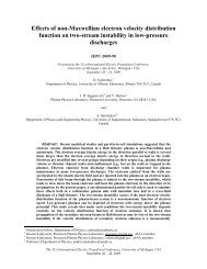
<strong>of</strong> thrust, power <strong>and</strong> total impulse are available Figure 3.<br />
Specific Impulse [s]<br />
3500<br />
3000<br />
2500<br />
2000<br />
1500<br />
1000<br />
500<br />
10 20 30 40 50 60 70<br />
Total Power [W]<br />
718µN<br />
613µN<br />
529µN<br />
449µN<br />
360µN<br />
294µN<br />
235µN<br />
159µN<br />
95µN<br />
51µN<br />
40µN<br />
Figure 3 <strong>RIT</strong>-µX Performance, Specific Impulse as<br />
function <strong>of</strong> total power <strong>and</strong> thrust level<br />
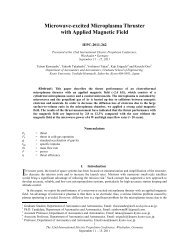
Figure 4 <strong>RIT</strong>-µX in operation<br />
Figure 3 shows, that <strong>the</strong> operational range is wider than <strong>the</strong> design target 50µN -500µN. Depending on <strong>the</strong><br />
total power also operation with higher thrust level is possible. Even at <strong>the</strong> lowest thrust level <strong>the</strong> specific impulse is<br />
higher than 500s.<br />
C. Electron back-streaming <strong>and</strong> perveance tests<br />
1. Electron back-streaming (EBS)<br />
The negative potential in <strong>the</strong> vicinity <strong>of</strong> <strong>the</strong> second grid has to shield <strong>the</strong> positive potential <strong>of</strong> <strong>the</strong> inner screen<br />
grid. O<strong>the</strong>rwise electrons would be attracted <strong>and</strong> accelerated towards <strong>the</strong> screen grid. This must be avoided<br />
o<strong>the</strong>rwise <strong>the</strong> screen grid could be damaged by <strong>the</strong> <strong>the</strong>rmal load <strong>of</strong> <strong>the</strong> high energy electrons. In addition, for a given<br />
power budget, EBS would result in a reduction <strong>of</strong> <strong>the</strong> thrust. EBS might occur at high ion current densities in<br />
combination with high voltages at <strong>the</strong> screen grid. For low thrust operation at low voltages EBS is not an issue.<br />
For <strong>the</strong> EBS test an electron source was installed in <strong>the</strong> test chamber. Operational parameters <strong>of</strong> <strong>the</strong> thruster were<br />
set according to <strong>the</strong> test procedure. Than <strong>the</strong> negative voltage at <strong>the</strong> accelerator grid was reduced in steps <strong>of</strong> 5 V<br />
towards zero. The test was repeated for different thrust levels. It was found that <strong>the</strong> threshold for EBS is far away<br />
from <strong>the</strong> typical operational voltage <strong>of</strong> <strong>the</strong> acceleration grid. Fur<strong>the</strong>rmore it has been turned out that operation with<br />
an <strong>the</strong>rmal electron emitter is less critical than operation with a hollow cathode for neutralization. In contrast to a<br />
hollow cathode which is able to deliver easily an additional amount <strong>of</strong> electrons <strong>the</strong> <strong>the</strong>rmal gas less device is very<br />
limited in <strong>the</strong> maximum electron current. Even in case EBS conditions at <strong>the</strong> grid system occur <strong>the</strong> limited number<br />
<strong>of</strong> available electrons is an effective protection against EBS.<br />
6<br />
The 31st International Electric Propulsion Conference, University <strong>of</strong> Michigan, USA<br />
September 20 – 24, 2009