Design Development and Test of the RIT-ÁX Mini Ion Engine System
Design Development and Test of the RIT-ÁX Mini Ion Engine System
Design Development and Test of the RIT-ÁX Mini Ion Engine System

You also want an ePaper? Increase the reach of your titles
YUMPU automatically turns print PDFs into web optimized ePapers that Google loves.
M<br />
<strong>Design</strong> <strong>Development</strong> <strong>and</strong> <strong>Test</strong> <strong>of</strong> <strong>the</strong> <strong>RIT</strong>-µX <strong>Mini</strong> <strong>Ion</strong><br />
<strong>Engine</strong> <strong>System</strong><br />
IEPC-2009-179<br />
Presented at <strong>the</strong> 31st International Electric Propulsion Conference,<br />
University <strong>of</strong> Michigan • Ann Arbor, Michigan • USA<br />
September 20 – 24, 2009<br />
Hans Leiter 1<br />
Astrium GmbH BL Equipment <strong>and</strong> Propulsion, P.O. 1119, 74215 Möckmühl, Germany<br />
Benjamin Lotz 2 <strong>and</strong> Davar Feili 3<br />
University <strong>of</strong> Gießen, Heinrich Buff Ring 16, 35392 Gießen, Germany<br />
Michael Tartz 4 <strong>and</strong> Horst Neumann 5<br />
IOM Leipzig, Permoserstr. 15, 04318 Leipzig Germany<br />
Davina Maria Di Cara 6<br />
ESA ESTEC, Keplerlaan 1, 2201 AZ Noordwijk, The Ne<strong>the</strong>rl<strong>and</strong>s<br />
Abstract: <strong>RIT</strong>-µX (Elegant BB) is a radio frequency ion thruster especially designed<br />
for <strong>the</strong> dem<strong>and</strong>s <strong>of</strong> high precision formation flying missions <strong>and</strong> <strong>the</strong> needs <strong>of</strong> fine <strong>and</strong> ultrafine<br />
drag control. The thruster design bases on <strong>the</strong> experience in more than 40 years radio<br />
frequency ion thruster development. The <strong>RIT</strong>-µX thruster <strong>and</strong> system development has been<br />
performed in <strong>the</strong> frame <strong>of</strong> ESA's GST program. This publication is focused on <strong>the</strong> results <strong>of</strong><br />
<strong>the</strong> thruster functional test program. During <strong>the</strong> functional test campaign <strong>the</strong> basis<br />
performance (Isp, Thrust, Power consumption) as well as advanced parameters (Thrust<br />
resolution, Controllability, Thrust Noise) have been investigated.<br />
I. Introduction<br />
iniaturized ion engines are considered as attractive solution to overcome difficulties <strong>and</strong> limitations <strong>of</strong><br />
existing propulsion concepts for low <strong>and</strong> lowest thrust application. Especially, mini ion engines are bridging<br />
<strong>the</strong> gap between <strong>the</strong> only available fine thrust devices from FEEP type (µN range) <strong>and</strong> classical electric propulsion<br />
systems working in <strong>the</strong> mN range.<br />
<strong>Mini</strong> ion engine systems will help to improve <strong>the</strong> system specific impulse <strong>and</strong> mission lifetime. They can<br />
provide highest thrust resolution, accuracy <strong>and</strong> controllability. Moreover mini ion engines are working with a very<br />
low level <strong>of</strong> thrust noise.<br />
. Astrium's miniaturized propulsion solution is called <strong>RIT</strong>-µX. The name "<strong>RIT</strong>-µX" follows Astrium's<br />
convention to label <strong>the</strong> Radio Frequency <strong>Ion</strong> Thrusters with an X as long as <strong>the</strong> thruster is in an early development<br />
status (see <strong>RIT</strong>-XT <strong>and</strong> <strong>RIT</strong>-22). The Greek "µ" emphasizes <strong>the</strong> special abilities <strong>of</strong> <strong>the</strong> engine for micro propulsion.<br />
1<br />
<strong>Development</strong> Electric Propulsion, TP 42, Hans.Leiter@astrium.eads.net.<br />
2<br />
1st Institute <strong>of</strong> Physics Benjamin.Lotz@physik.uni-giessen.de<br />
3<br />
1st Institute <strong>of</strong> Physics Davar.Feili@physik.uni-giessen.de<br />
4<br />
Senior Researcher Michael.Tartz@iom-leipzig.de<br />
5<br />
HoG Horst.Neumann@iom-leipzig.de<br />
6<br />
TOS/MPE, davina.maria.di.cara@esa.int<br />
1<br />
The 31st International Electric Propulsion Conference, University <strong>of</strong> Michigan, USA<br />
September 20 – 24, 2009
The work presented in this publication has been performed under a contract granted by <strong>the</strong> European Space<br />
Agency ESA in <strong>the</strong> frame <strong>of</strong> <strong>the</strong> GSTP programs. Under lead <strong>of</strong> Astrium Space Transportation, Business Line<br />
"Equipment <strong>and</strong> Propulsion" a study <strong>and</strong> development team has been formed bringing toge<strong>the</strong>r <strong>the</strong> competences in<br />
all relevant fields. Astrium is a well known system house with a long term heritage in electric propulsion. For more<br />
than 4 decades a fruitful co-operation with Giessen University has been existing. The Radio Frequency principle was<br />
invented in Giessen in <strong>the</strong> early sixties <strong>of</strong> <strong>the</strong> last century by pr<strong>of</strong>essor Horst.W. Loeb, later-on a whole family <strong>of</strong> ion<br />
engine prototypes was developed under his lead [7][8] [9].<br />
During <strong>the</strong> last years Giessen University has focused its activities on micro-propulsion [1] [3]. The successful<br />
work that had been performed [10] was <strong>the</strong> basis for <strong>the</strong> activities described here. Naturally, Giessen University is a<br />
strong partner in this project. Giessen University provides knowledge <strong>of</strong> thruster physics, scaling <strong>and</strong> layout.<br />
Moreover Giessen provides test services for development <strong>and</strong> endurance testing. Ano<strong>the</strong>r experienced long-term<br />
partner in <strong>RIT</strong> development is <strong>the</strong> Institute for Surface Modification (IOM) Leipzig. The IOM has <strong>the</strong> lead for ion<br />
optics <strong>and</strong> lifetime analysis.<br />
Although hardware activities are limited to <strong>the</strong> ion engine itself <strong>the</strong> <strong>RIT</strong>-µX project comprises system<br />
engineering too. An essential part for any ion engine is <strong>the</strong> required power supply <strong>and</strong> control logic (PSCU).<br />
Elaboration <strong>of</strong> <strong>the</strong> electronics system is performed by Astrium Satellites GmbH (Friedrichshafen). <strong>Design</strong> <strong>and</strong> layout<br />
<strong>of</strong> <strong>the</strong> flow management system is supported by University <strong>of</strong> Stuttgart, Institute for Space <strong>System</strong>s (IRS).<br />
This publication is focused on <strong>the</strong> functional test results obtained during <strong>the</strong> project. A more detailed description<br />
<strong>of</strong> <strong>the</strong> potential system has been yet published [11].<br />
II. Typical low thrust missions<br />
Reducing <strong>the</strong> altitude <strong>of</strong> earth observing satellites in low earth orbits evidently increases <strong>the</strong> resolution <strong>of</strong> <strong>the</strong><br />
data from <strong>the</strong> measuring instrumentation. On <strong>the</strong> o<strong>the</strong>r h<strong>and</strong> <strong>the</strong> atmosphere's influence on <strong>the</strong> spacecraft increases.<br />
A compensation <strong>of</strong> <strong>the</strong> atmospheric drag becomes m<strong>and</strong>atory. This is challenging for <strong>the</strong> propulsion system, as<br />
high thrust controllability <strong>and</strong> resolution is required combined with sufficient total impulse. Moreover <strong>the</strong> high<br />
amount <strong>of</strong> atomic Oxygen requires a robustness <strong>of</strong> <strong>the</strong> engine against this aggressive element. Concerns with respect<br />
to any technology which requires (hot) cathodes exists.<br />
The installation <strong>of</strong> formation flying satellites forming one large virtual instrument <strong>of</strong>fering a significant higher<br />
resolution than any large single instrument is considered as a break through for several types <strong>of</strong> (deep) space<br />
observation missions. Such experiments will deliver important impacts for fundamental physics <strong>and</strong> our<br />
underst<strong>and</strong>ing <strong>of</strong> <strong>the</strong> universe. For <strong>the</strong>se formations again <strong>the</strong> controllability <strong>and</strong> <strong>the</strong> thrust resolution are from<br />
importance. High specific impulse <strong>and</strong> total impulse are highly desirable to maintain <strong>the</strong> experiments over years.<br />
Ultra fine thrust control is required for some missions dealing with <strong>the</strong> measurement <strong>of</strong> gravity waves. Goal is a<br />
propulsion system with a thrust starting with zero to some tenth (hundreds) <strong>of</strong> micro Newtons. As <strong>the</strong>se experiments<br />
will take place far from Earth, for example at <strong>the</strong> Lagrangian point L2 also a higher thrust in <strong>the</strong> range <strong>of</strong> some milli<br />
Newtons for <strong>the</strong> cruise phase to <strong>the</strong> destination is required.<br />
III. The <strong>RIT</strong>-µX <strong>Ion</strong> Thruster Technology<br />
A. <strong>RIT</strong>-µX Basics<br />
Heart <strong>of</strong> <strong>the</strong> new <strong>RIT</strong>-µX small ion propulsion system is <strong>the</strong> radio frequency ion thruster <strong>RIT</strong>-µX with <strong>the</strong><br />
unique electrodeless ionization <strong>of</strong> <strong>the</strong> propellant by electromagnetic waves. RF-ionization is known as a very<br />
effective way to ionise neutral gases. The implementation <strong>of</strong> this ionisation principle is very simple as merely two<br />
components are necessary: An ionisation chamber made <strong>of</strong> an isolating material <strong>and</strong> an RF-coil which surrounds<br />
this chamber. No o<strong>the</strong>r parts are required inside or outside <strong>the</strong> ioniser with respect to ionisation <strong>of</strong> <strong>the</strong> propellant!<br />
This makes <strong>the</strong> overall concept very simple, robust <strong>and</strong> erosion free.<br />
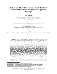
If an RF-current is applied to <strong>the</strong> <strong>the</strong> thrusters RF-coil a primary axial magnetic field is induced inside <strong>the</strong><br />
ioniser. This field generates a secondary circular electric field (E). Whereas <strong>the</strong> effect <strong>of</strong> this electro-magnetic field<br />
on neutrals or ions is negligible, free electrons gain sufficient energy for impact ionisation <strong>of</strong> <strong>the</strong> propellant: The<br />
propellant is set into <strong>the</strong> plasma state. Once <strong>the</strong> ionisation process is initially triggered <strong>the</strong> process is self-sustaining.<br />
All electrons required for a steady state operation are generated in <strong>the</strong> discharge itself. There is no need for an<br />
additional electron source, e.g. a main cathode, inside <strong>the</strong> ionisation chamber.<br />
2<br />
The 31st International Electric Propulsion Conference, University <strong>of</strong> Michigan, USA<br />
September 20 – 24, 2009
In ion thruster technology <strong>the</strong> rf-principle is unique, but <strong>the</strong>re exists a broad field <strong>of</strong> applications where rfionization<br />
is used. It is employed in plasma- <strong>and</strong> ion sources for material processing (solid state physics,<br />
semiconductors, plasma chemistry…) as well as for neutral injector sources for fusion plasma heating. So <strong>the</strong><br />
physics behind are well understood. Some special properties, which also apply for ion thrusters, make <strong>the</strong> RFplasma<br />
very favourable for propulsion purposes <strong>and</strong> especially for micro propulsion.<br />
B. Physical Background<br />
High Discharge Efficiency: The plasma generation by RF is one <strong>of</strong> <strong>the</strong> most efficient methods to set a gas in <strong>the</strong><br />
ionized plasma state. The efficiency is so high that no additional support, like external magnetic fields for plasma<br />
confinement is required. RF-thrusters work without permanent magnets or additional solenoid.<br />
Low Electron Temperature: [5][6]The plasma’s electron temperature is comparably lower than for Kaufman<br />
thrusters. Therefore <strong>the</strong> potential drop, which in a first order is directly proportional to <strong>the</strong> electron temperature,<br />
between <strong>the</strong> quasi neutral inner plasma <strong>and</strong> its surroundings remains below <strong>the</strong> sputter thresholds <strong>of</strong> <strong>the</strong> materials<br />
used for <strong>the</strong> ionisation chamber <strong>and</strong> <strong>the</strong> screen grid. Nei<strong>the</strong>r <strong>the</strong> plasma sided grid nor <strong>the</strong> ionisation chamber are<br />
subject to any kind <strong>of</strong> erosion processes.<br />
Beam<br />
Neutralisation<br />
<strong>Ion</strong><br />
Production<br />
<strong>Ion</strong><br />
Acceleration<br />
Acceleration<br />
<strong>RIT</strong>-µX <strong>Ion</strong> Thruster<br />
A = Acceleration Grid<br />
S = Screen Grid<br />
Io = <strong>Ion</strong>isation Chamber<br />
Neut = Neutraliser<br />
Ins = Gas Inlet <strong>and</strong> isolator<br />
Rf = Radio Frequency Generator<br />
Figure 1 Operating Principle <strong>of</strong> an RF-<strong>Ion</strong> Thruster <strong>and</strong> <strong>RIT</strong>-µX elegant breadboard.<br />
Low amount <strong>of</strong> multiply charged ions: [5] The power to thrust ratio <strong>of</strong> any gridded ion engine is increased, if<br />
multiple charged ions occur in <strong>the</strong> ion beam. A low electron temperature means a very small amount <strong>of</strong> multiple<br />
charged ions in <strong>the</strong> ioniser <strong>and</strong> <strong>the</strong> ion beam. The low amount (typ.
an efficient ionisation whereas <strong>the</strong> magnetic field is necessary for ECR-Thrusters to establish <strong>the</strong> electron cyclotron<br />
resonance conditions. Using permanent magnets <strong>the</strong> operational temperature <strong>of</strong> <strong>the</strong> thruster is limited to <strong>the</strong><br />
magnet’s Curie temperature TC which is typically in <strong>the</strong> range <strong>of</strong> 300°C. Some Kaufman-<strong>Engine</strong>s omit <strong>the</strong><br />
permanent magnets by using electromagnets with coils instead. The required number <strong>of</strong> turns for <strong>the</strong>se coils makes<br />
an electrical isolation indispensable. Therefore <strong>the</strong> <strong>the</strong>rmal restrictions are quite similar to that <strong>of</strong> permanent<br />
magnets. In contrast, <strong>the</strong> RF-coil <strong>of</strong> <strong>the</strong> <strong>RIT</strong>-Thruster is not covered by isolating materials because <strong>the</strong> distance from<br />
turn to turn is sufficient to achieve isolation.<br />
Inherent High Voltage Isolation: The ionized propellant (plasma) is an excellent electrical conductor. So <strong>the</strong><br />
high voltage provided to <strong>the</strong> screen grid (or an anode) is "visible" for any component in contact with <strong>the</strong> plasma. In<br />
case <strong>of</strong> <strong>the</strong> <strong>RIT</strong> this voltage is inherently isolated from surroundings. The non-conductive ionizer vessel is a natural<br />
barrier. In a <strong>RIT</strong> system only <strong>the</strong> cabling to <strong>the</strong> grid is on high voltage potential. In Kaufman engines also <strong>the</strong> entire<br />
cathode system <strong>and</strong> <strong>the</strong> anode are on high potential. Special care is required, also for <strong>the</strong> layout <strong>of</strong> <strong>the</strong> PPU where<br />
several modules are on high voltage potential [4].<br />
Thrust control: The clear relationship between applied RF-power <strong>and</strong> extractable ion current <strong>and</strong> <strong>the</strong> inherent<br />
stability <strong>of</strong> <strong>the</strong> ionisation <strong>of</strong>fer an effective thrust control strategy. Also without any regulation <strong>the</strong> beam current is<br />
constant as long as no o<strong>the</strong>r operational parameters alter (e.g. mass flow). For example, stability better than 0.3%<br />
over 100h was multiply demonstrated with <strong>the</strong> large <strong>RIT</strong>-22 engine. During this test no active thrust regulation was<br />
employed. With a simple closed loop between ion beam <strong>and</strong> RF-supply a high precision thrust control is realized.<br />
The stability only depends on <strong>the</strong> accuracy <strong>of</strong> <strong>the</strong> employed electronics. Nei<strong>the</strong>r external magnetic fields have to be<br />
controlled nor does any restriction by additional fields apply. Using high precision laboratory power supplies <strong>and</strong> <strong>the</strong><br />
closed loop concept <strong>the</strong> thrust stability achieved with <strong>RIT</strong>-22 is better than 0.1‰ (+/- 1mA @ 2380mA beam current)<br />
Ultra Fast Thrust Control: If <strong>the</strong> rf-power is varied <strong>the</strong> ionization responses to a new equilibrium within some<br />
rf-periods. So within a few microseconds <strong>the</strong> thrust reaches a new state. The time thrust resolution <strong>of</strong> <strong>the</strong> overall<br />
propulsion system depends on <strong>the</strong> speed <strong>of</strong> <strong>the</strong> electronics around <strong>the</strong> engine. It is not limited by <strong>the</strong> thruster itself.<br />
In contrast to <strong>the</strong> rf-ionization any engines requiring cathodes are limited in <strong>the</strong>re response by <strong>the</strong> <strong>the</strong>rmal capacity<br />
<strong>of</strong> <strong>the</strong> cathode.<br />
Thrust noise: The inherent thrust stability in combination with <strong>the</strong> fast thrust response <strong>of</strong>fers excellent low thrust<br />
noise. The extreme low thrust noise is a challenge for any measurement.<br />
IV. <strong>RIT</strong>-µX <strong>Ion</strong> Thruster <strong>System</strong><br />
During <strong>the</strong> system design phase, architectures with two, four, eight <strong>and</strong> twelve engines have been investigated.<br />
The work was performed for three levels <strong>of</strong> thrust. In addition to <strong>the</strong> mini rf-ion engine also power supply <strong>and</strong><br />
control unit PSCU <strong>and</strong> flow control system have been investigated in detail. Results are subject <strong>of</strong> <strong>the</strong> dedicate<br />
<strong>System</strong> <strong>Design</strong> Report. The description in this section is focused on <strong>the</strong> principle function <strong>of</strong> all mini ion engine<br />
system components.<br />
<strong>RIT</strong>A - Radi<strong>of</strong>requecy <strong>Ion</strong> Thruster<br />
Assembly<br />
PPU<br />
- Power<br />
Processing<br />
Unit<br />
FCU<br />
- Flow<br />
Control<br />
Unit<br />
TU<br />
<strong>RIT</strong> Thruster<br />
Unit<br />
- <strong>Ion</strong> Thruster<br />
- Neutralizer<br />
- RF Generator<br />
<strong>RIT</strong>-µX - Radi<strong>of</strong>requecy <strong>Ion</strong> Thruster<br />
Assembly<br />
PPU<br />
- Power<br />
Processing<br />
Unit<br />
FCU<br />
- Flow<br />
Control<br />
Unit<br />
Neutralizer<br />
<strong>RIT</strong>-µX<br />
<strong>RIT</strong> Thruster<br />
Unit<br />
- <strong>Ion</strong> Thruster<br />
- RF Generator<br />
Figure 2 Comparison - Conventional Radio Frequency <strong>Ion</strong> <strong>Engine</strong> <strong>System</strong> (Left) vs. <strong>Mini</strong> <strong>Ion</strong> <strong>Engine</strong> <strong>System</strong><br />
(Right)<br />
4<br />
The 31st International Electric Propulsion Conference, University <strong>of</strong> Michigan, USA<br />
September 20 – 24, 2009
A <strong>RIT</strong>-µX ion engine requires propellant <strong>and</strong> electricity for operation. The propellant flow to <strong>the</strong> engine is<br />
controlled by a flow control unit (FCU), <strong>the</strong> required electric power is provided by <strong>the</strong> power processing unit (PPU).<br />
The PPU controls also <strong>the</strong> FCU.<br />
In contrast to <strong>the</strong> larger <strong>RIT</strong> engines like <strong>RIT</strong>-10 <strong>and</strong> <strong>RIT</strong>-22 it is possible to use gasless neutralizers, at least for<br />
low thrust (< 500 µN). Therefore no xenon flow management is required for <strong>the</strong> neutralizer. Fur<strong>the</strong>rmore it is not<br />
necessary to have one neutralizer dedicated to one thruster. It is important only that <strong>the</strong> total ion current expelled<br />
from all thrusters becomes completely compensated.<br />
<strong>RIT</strong>-µX <strong>Ion</strong> Thruster<br />
• Expels ions <strong>and</strong> produces thrust<br />
Neutralizer<br />
• Emits electrons to compensate ion current from<br />
thruster<br />
Radio Frequency Generator<br />
• Convert DC current into AC current (rf current)<br />
FCU<br />
• Regulate xenon flow to thruster<br />
Table 1 Components <strong>of</strong> a mini ion engine system<br />
PPU<br />
• Provides positive high voltage (defines beam<br />
potential <strong>and</strong> exhaust velocity)<br />
• Provide negative high voltage (optimizes ion<br />
extraction <strong>and</strong> prevents back streaming <strong>of</strong><br />
electrons into <strong>the</strong> thruster<br />
• Provide power for radio-frequency generator<br />
• Provide voltages for neutralizer<br />
• Measure <strong>and</strong> control beam current (thrust<br />
respectively) in close loop<br />
• Provide voltages for FCU<br />
• Control FCU<br />
• Exception h<strong>and</strong>ling etc.<br />
Please note: FCU, Neutralizer <strong>and</strong> PPU can serve multiple thrusters (cf. topologies). A detailed description exceeds<br />
<strong>the</strong> scope <strong>of</strong> this paper. For additional information refer to [2] [11] e.g.<br />
V. <strong>RIT</strong>-µX <strong>Test</strong>s <strong>and</strong> Results<br />
A. Overview<br />
In August, 2008 <strong>RIT</strong>-µX was subject to an extensive functional test campaign. Highlights <strong>of</strong> <strong>the</strong> test campaign<br />
were:<br />
• Performance characterization<br />
- Power consumption<br />
- Specific impulse<br />
- Thrust Range<br />
• Perveance measurements<br />
- Dynamic range <strong>of</strong> ion optics (grid system)<br />
• Electron back streaming test<br />
• Thrust dynamics<br />
- thrust stepping<br />
- thrust linearity<br />
• Thrust stability <strong>and</strong> noise measurement<br />
These tests were embedded in a typical test program with mass inspections, electrical checks <strong>and</strong> visual<br />
inspections. All tests were performed in <strong>the</strong> Bic-Mac <strong>Test</strong> facility <strong>of</strong> <strong>the</strong> first institute <strong>of</strong> physics in Gießen. Gießen<br />
University also provided <strong>the</strong> flow control system <strong>and</strong> all required electronics. The setup included a beam current<br />
controller developed by <strong>the</strong> institute.<br />
The ionizer <strong>and</strong> <strong>the</strong> carriers for <strong>the</strong> <strong>RIT</strong>-µX grid system are manufactured in alumina (ceramics). Manufacturing<br />
<strong>of</strong> <strong>the</strong>se parts is time consuming. To avoid additional delays in <strong>the</strong> schedule, <strong>the</strong>se parts have been additionally<br />
5<br />
The 31st International Electric Propulsion Conference, University <strong>of</strong> Michigan, USA<br />
September 20 – 24, 2009
manufactured from macor. These parts were used for <strong>the</strong> functional tests because indeed <strong>the</strong> original alumina parts<br />
were not delivered in time.<br />
It is anticipated that all data obtained during <strong>the</strong> functional test were in accordance with <strong>the</strong> predictions made in<br />
<strong>the</strong> study <strong>and</strong> design phase. However, <strong>the</strong> thruster performance using macor is lower than <strong>the</strong> performance using<br />
alumina. It means <strong>the</strong> data provided here are to be considered as "worst case". For <strong>the</strong> 1,500 hour endurance test <strong>the</strong><br />
ceramic parts were used.<br />
B. Performance characterisation<br />
During <strong>the</strong> performance mapping <strong>the</strong> ion current is kept constant <strong>and</strong> <strong>the</strong> required rf-power is measured as a<br />
function <strong>of</strong> <strong>the</strong> xenon flow into <strong>the</strong> engine. The test is repeated for different current levels. Toge<strong>the</strong>r with <strong>the</strong> power<br />
for <strong>the</strong> beam acceleration <strong>the</strong> total power can be derived. Finally <strong>the</strong> thrust is calculated <strong>and</strong> all data for calculation<br />
<strong>of</strong> thrust, power <strong>and</strong> total impulse are available Figure 3.<br />
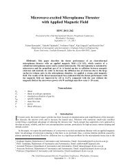
Specific Impulse [s]<br />
3500<br />
3000<br />
2500<br />
2000<br />
1500<br />
1000<br />
500<br />
10 20 30 40 50 60 70<br />
Total Power [W]<br />
718µN<br />
613µN<br />
529µN<br />
449µN<br />
360µN<br />
294µN<br />
235µN<br />
159µN<br />
95µN<br />
51µN<br />
40µN<br />
Figure 3 <strong>RIT</strong>-µX Performance, Specific Impulse as<br />
function <strong>of</strong> total power <strong>and</strong> thrust level<br />
Figure 4 <strong>RIT</strong>-µX in operation<br />
Figure 3 shows, that <strong>the</strong> operational range is wider than <strong>the</strong> design target 50µN -500µN. Depending on <strong>the</strong><br />
total power also operation with higher thrust level is possible. Even at <strong>the</strong> lowest thrust level <strong>the</strong> specific impulse is<br />
higher than 500s.<br />
C. Electron back-streaming <strong>and</strong> perveance tests<br />
1. Electron back-streaming (EBS)<br />
The negative potential in <strong>the</strong> vicinity <strong>of</strong> <strong>the</strong> second grid has to shield <strong>the</strong> positive potential <strong>of</strong> <strong>the</strong> inner screen<br />
grid. O<strong>the</strong>rwise electrons would be attracted <strong>and</strong> accelerated towards <strong>the</strong> screen grid. This must be avoided<br />
o<strong>the</strong>rwise <strong>the</strong> screen grid could be damaged by <strong>the</strong> <strong>the</strong>rmal load <strong>of</strong> <strong>the</strong> high energy electrons. In addition, for a given<br />
power budget, EBS would result in a reduction <strong>of</strong> <strong>the</strong> thrust. EBS might occur at high ion current densities in<br />
combination with high voltages at <strong>the</strong> screen grid. For low thrust operation at low voltages EBS is not an issue.<br />
For <strong>the</strong> EBS test an electron source was installed in <strong>the</strong> test chamber. Operational parameters <strong>of</strong> <strong>the</strong> thruster were<br />
set according to <strong>the</strong> test procedure. Than <strong>the</strong> negative voltage at <strong>the</strong> accelerator grid was reduced in steps <strong>of</strong> 5 V<br />
towards zero. The test was repeated for different thrust levels. It was found that <strong>the</strong> threshold for EBS is far away<br />
from <strong>the</strong> typical operational voltage <strong>of</strong> <strong>the</strong> acceleration grid. Fur<strong>the</strong>rmore it has been turned out that operation with<br />
an <strong>the</strong>rmal electron emitter is less critical than operation with a hollow cathode for neutralization. In contrast to a<br />
hollow cathode which is able to deliver easily an additional amount <strong>of</strong> electrons <strong>the</strong> <strong>the</strong>rmal gas less device is very<br />
limited in <strong>the</strong> maximum electron current. Even in case EBS conditions at <strong>the</strong> grid system occur <strong>the</strong> limited number<br />
<strong>of</strong> available electrons is an effective protection against EBS.<br />
6<br />
The 31st International Electric Propulsion Conference, University <strong>of</strong> Michigan, USA<br />
September 20 – 24, 2009
2. Perveance test<br />
The perveance tests are intended for identification <strong>of</strong> <strong>the</strong> thruster's<br />
• Direct impingement mode (prohibited for normal thruster operation)<br />
• Nominal operation mode<br />
• Over-crossing mode (prohibited for nominal thruster operation)<br />
In both prohibited modes <strong>the</strong> acceleration grid is hit by ions with maximum energy gained in <strong>the</strong> electric field<br />
between <strong>the</strong> grids. The impingement <strong>of</strong> <strong>the</strong> fast ions results in a high erosion rate <strong>and</strong> severe grid damage.<br />
The perveance test has shown that <strong>the</strong> useful ion optics range <strong>of</strong> <strong>the</strong> grid system is in line with <strong>the</strong> prediction:<br />
No indications for over-crossing or direct impingement have been found at <strong>the</strong> intended operational points.<br />
D. Dynamics<br />
1. Controllability <strong>and</strong> thrust linearity<br />
This section describes <strong>the</strong> dynamic features <strong>of</strong> a <strong>RIT</strong>-µX. Figure 6 illustrate a thrust stepping in <strong>the</strong> thrusters<br />
nominal thrust range from 50-500µN starting at an intermediate level <strong>of</strong> 250 µN <strong>the</strong> thrust was comm<strong>and</strong>ed down in<br />
steps <strong>of</strong> 50µN until <strong>the</strong> lowest nominal thrust level is reached. Then <strong>the</strong> thrust is increased in steps <strong>of</strong> same size until<br />
<strong>the</strong> upper (nominal) thrust level is reached. On each thrust level <strong>the</strong> engine is operated for 300 s<br />
The function between comm<strong>and</strong>ed thrust <strong>and</strong> engine thrust is plotted in Figure 6. A linear function describes <strong>the</strong><br />
behaviour excellently.<br />
2. Thrust resolution<br />
It is very difficult for some propulsion systems to follow small comm<strong>and</strong>ed steps <strong>of</strong> thrust variation as well as<br />
large comm<strong>and</strong>ed steps. Figure 7 shows <strong>the</strong> <strong>RIT</strong>-µX behaviour. The thrust was increased from 250µN to 500µN<br />
<strong>and</strong> vice versa performing <strong>the</strong> large 250µN jump. On <strong>the</strong> high 500µN thrust level micro steps (+/- 1 µN, +/- 2 µN,<br />
+/-5 µN, +/- 10 µN) were performed. The thruster has mastered both tasks excellently.<br />
3. Thrust Noise<br />
All thrust noise measurements were performed over night to minimize environmental impacts starting 19.30 in<br />
<strong>the</strong> evening <strong>and</strong> completed by 11:00 <strong>the</strong> following morning. In Figure 9 thrust versus time is plotted. The window<br />
used for data evaluation is marked with a blue box (12 hours). Typically, <strong>the</strong> thrust is constant in a b<strong>and</strong> +/-0.1µN<br />
(0.02%). When <strong>the</strong> main door <strong>of</strong> Gießen Laboratory, where <strong>the</strong> facility is hosted, was opened <strong>the</strong> average thrust<br />
increases by 0.1µN. It is most probably caused by a small variation in <strong>the</strong> mass flow <strong>of</strong> <strong>the</strong> commercial flow<br />
controller. As <strong>the</strong> beam current controller is not optimized for 500 µN thrust it does not suppress <strong>the</strong> weak deviation<br />
<strong>of</strong> thrust.<br />
Data were recorded at frequency <strong>of</strong> 10 Hz. The result is plotted in Figure 10. The "electrical thrust noise" is<br />
lower than <strong>the</strong> requirements for LISA except peaks at 2 Hz. This is <strong>the</strong> frequency <strong>of</strong> <strong>the</strong> cryogenic pumping system.<br />
The probability that <strong>the</strong> effect is introduced via <strong>the</strong> grid system is considered low. As <strong>the</strong> coil is not hard-mounted to<br />
<strong>the</strong> thruster is can vibrate relative to <strong>the</strong> discharge vessel. For a clear identification additional work is required.<br />
7<br />
The 31st International Electric Propulsion Conference, University <strong>of</strong> Michigan, USA<br />
September 20 – 24, 2009
Thrust [µN]<br />
500<br />
450<br />
400<br />
350<br />
300<br />
250<br />
200<br />
150<br />
100<br />
50<br />
12:00 01:00 02:00 03:00 04:00 05:00 06:00 07:00<br />
Time [hh:mm]<br />
THRUST<br />
Figure 5 <strong>RIT</strong>-µX 50µN Thrust stepping Figure 6 Thrust linearity<br />
Thrust [µN]<br />
550<br />
500<br />
450<br />
400<br />
350<br />
300<br />
250<br />
200<br />
06:15 06:30 06:45 07:00 07:15 07:30 07:45<br />
Time [hh:mm]<br />
THRUST<br />
Figure 7 Thrust Stepping I - wide thrust range<br />
variation<br />
Thrust [µN]<br />
500.5<br />
500.4<br />
500.3<br />
500.2<br />
500.1<br />
500.0<br />
499.9<br />
499.8<br />
499.7<br />
499.6<br />
Window for Data Evaluation<br />
499.5<br />
04:30 07:30 10:30 01:30 04:30 07:30 10:30<br />
Time [hh:mm]<br />
THRUST<br />
Main Door <strong>of</strong> Gießen<br />
<strong>Test</strong> Vacility opened<br />
0<br />
0 100 200 300 400 500<br />
8<br />
The 31st International Electric Propulsion Conference, University <strong>of</strong> Michigan, USA<br />
September 20 – 24, 2009<br />
Thrust Response Value [µN]<br />
Thrust [µN]<br />
500<br />
400<br />
300<br />
200<br />
100<br />
510<br />
505<br />
500<br />
495<br />
490<br />
Thrust Set-Value [µN]<br />
THRUST<br />
Linear Fit <strong>of</strong> Dlin3_THRUST<br />
06:40 06:45 06:50 06:55 07:00 07:05 07:10 07:15 07:20 07:25<br />
Time<br />
THRUST<br />
Figure 8 Thrust Variation II - Small varaitions on <strong>the</strong><br />
maximum nominal thrust level<br />
Thrust Noise Density [N/Hz^0.5]<br />
1E-5<br />
1E-6<br />
1E-7<br />
1E-8<br />
LISA Requirement<br />
Frequency <strong>of</strong><br />
Cryo Pumps<br />
1E-9<br />
1E-4 1E-3 0.01 0.1 1 10<br />
Frequency [Hz]<br />
Figure 9 Thrust vs. time plot for <strong>the</strong> 500µN Figure 10 Thrust noise density - 500µN Thrust
VI. Conclusion <strong>and</strong> Outlook<br />
The development <strong>of</strong> a <strong>RIT</strong>-µX miniaturized ion engine elegant breadboard model has been successfully<br />
completed. In an extensive functional test campaign <strong>the</strong> basic thruster performance has been mapped. For <strong>the</strong><br />
desired thrust range, 50-500µN, specific impulse <strong>and</strong> power consumption are available. The performance has been<br />
mapped also for lower <strong>and</strong> higher thrust levels. When sufficient power is available on board <strong>the</strong> spacecraft, <strong>RIT</strong>-µX<br />
is fully operable in an extended thrust range. With pervance tests <strong>the</strong> full thrust range has been validated with<br />
respect to <strong>the</strong> dynamic <strong>of</strong> ion optics. EBS tests showed that <strong>the</strong> dangerous effect <strong>of</strong> back streaming electrons is not<br />
critical for small ion engines. Especially, when operated with a gasless neutralizer <strong>the</strong> maximum available electron<br />
current is limited. Moreover, <strong>the</strong> ion optics design shows ample margins.<br />
Controllability <strong>and</strong> thrust noise are key issues for high precision low thrust systems. <strong>RIT</strong>-µX shows an<br />
impressive performance: The function between comm<strong>and</strong>ed thrust <strong>and</strong> thrust response is highly linear. The engine<br />
is mastering both small thrust variations <strong>and</strong> large thrust stepping. A thrust resolution better than +/- 0.1µN is found.<br />
The tests show clearly that that <strong>the</strong> limits for thrust resolution <strong>and</strong> controllability are given by <strong>the</strong> thruster electronics<br />
<strong>and</strong> not by <strong>the</strong> thruster itself.<br />
Finally, first thrust noise measurements have been performed. The measurement shows an electric thrust noise<br />
even bellow <strong>the</strong> limits for ESA's challenging LISA mission.<br />
In a first endurance test <strong>the</strong> engine has been operated for more than 1,700 hours at a constant thrust level <strong>of</strong> 500<br />
µN. The results will be published in a separate document.<br />
Meanwhile <strong>the</strong> European Space Agency has extended <strong>the</strong> baseline contract for <strong>the</strong> described activity. In <strong>the</strong><br />
frame <strong>of</strong> <strong>the</strong> extension all steps for <strong>the</strong> <strong>RIT</strong>-µX qualification will be performed. Completion <strong>of</strong> <strong>the</strong> qualification is<br />
scheduled for <strong>the</strong> second half <strong>of</strong> 2010. In parallel, ESA has granted contracts for <strong>the</strong> development <strong>of</strong> thruster<br />
electronics (Astrium Satellites, Friedrichshafen, D) <strong>and</strong> a dedicated flow control unit (Nanospace, S). A coupled<br />
system test is planned before end <strong>of</strong> 2010.<br />
References<br />
[1] D. Feili et al.: <strong>Test</strong>ing <strong>of</strong> New µN-<strong>RIT</strong>s at Giessen, AIAA-2005-4263<br />
41st AIAA/ASME/SAE/ASEE Joint Propulsion Conference, Tucson, Arizona, July 10-13, 2005<br />
[2] H.Leiter et al. “<strong>RIT</strong>-µX - High Precision Micro <strong>Ion</strong> Propulsion <strong>System</strong> Based on RF-Technology”, 43rd<br />
AIAA/ASME/SAE/ASEE Joint Propulsion Conference <strong>and</strong> Exhibit, Cincinnati, OH, July 8-11, 2007, No. AIAA-<br />
2007-5250<br />
[3]Horst W. Loeb et al.: <strong>Development</strong> <strong>of</strong> a <strong>RIT</strong>-Millithruster, IAC-04-S.4.04<br />
55th International Astronautical Congress, Vancouver, Canada, Oct. 4-8, 2004<br />
[4] Hans J. Leiter et al.: <strong>RIT</strong>15S - A radio frequency ion engine for high specific impulse operation, AIAA-2001-3491, 37th<br />
Joint Propulsion Conference, Salt Lake City, UT, July 8-11, 2001<br />
[5] M. Zeuner et al.: <strong>Ion</strong> Beam Characterisation <strong>of</strong> <strong>the</strong> <strong>RIT</strong> 10 <strong>Ion</strong> Thruster, AIAA-2003-5009, 39th AIAA/ASME/SAE/ASEE<br />
Joint Propulsion Conference <strong>and</strong> Exhibit, Huntsville, Alabama, July 20-23, 2003<br />
[6] S. Weis et al.: An Imaging Spectroscopy <strong>System</strong> Based On Multi-Fiber Optic For Investigation Of <strong>Ion</strong>- And Plasma<br />
Thrusters, Proceedings Space Propulsion, 2.- 9.Juni 2004, Chia Laguna (Cagliari) Sardinien (Italien)<br />
[7] [H.J. Leiter et al.:Perfomance Inprovement <strong>of</strong> Radi<strong>of</strong>requency <strong>Ion</strong> Thrusters - The Evolution <strong>of</strong> <strong>the</strong> <strong>RIT</strong> 15 <strong>Ion</strong>, <strong>Engine</strong>, 26th<br />
International Electric Propulsion Conference, Kokuro-kita, Kitkyushu, Japan, 17.-21. Oktober 1999, Paper No. IEPC-99-154<br />
[8] H.J. Leiter et al.: <strong>RIT</strong> 15 S und <strong>RIT</strong> 15 LP - The <strong>Development</strong> <strong>of</strong> High Performance Mission Optimized <strong>Ion</strong> Thrusters, 35th<br />
Joint Propulsion Conference, Los Angeles, CA, 20.-24. Juni 1999, AIAA-Paper, No. 99-2444<br />
[9] Horst Loeb et al.: Forty-years <strong>of</strong> Giessen EP-Activities <strong>and</strong> <strong>the</strong> recent µN-<strong>RIT</strong>, IEPC-2005-031<br />
[10]Davar Feili et al.: Performance Mapping <strong>of</strong> new µN-<strong>RIT</strong>s at Giessen, IPEC-2005-252<br />
[11] H.Leiter et al. <strong>RIT</strong>-µX - The New Modular High Precision Micro <strong>Ion</strong> Propulsion <strong>System</strong> IEPC-2007-209<br />
9<br />
The 31st International Electric Propulsion Conference, University <strong>of</strong> Michigan, USA<br />
September 20 – 24, 2009