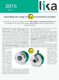
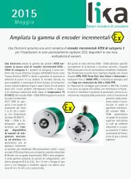
LINEPULS & LINECOD catalogue 2016 in English
Lika Electronic incremental and absolute linear encoders catalogue 2016 in English Our new linear encoders catalogue is out now, and features many innovative new products and up-to-date information. The catalogue is expressly designed to set out the comprehensive range of incremental & absolute linear encoders from Lika Electronic. Check it out, it is completely renewed! Make sure you don’t miss out on a copy, download the pdf file from our web site or request your hard copy now! We have also got an interactive digital version in the works that shall be released soon!
Lika Electronic incremental and absolute linear encoders catalogue 2016 in English
Our new linear encoders catalogue is out now, and features many innovative new products and up-to-date information. The catalogue is expressly designed to set out the comprehensive range of incremental & absolute linear encoders from Lika Electronic. Check it out, it is completely renewed!
Make sure you don’t miss out on a copy, download the pdf file from our web site or request your hard copy now!
We have also got an interactive digital version in the works that shall be released soon!

Create successful ePaper yourself
Turn your PDF publications into a flip-book with our unique Google optimized e-Paper software.
<strong>LINECOD</strong><br />
Additional functions for analogue encoders<br />
Fault output connected to a relay<br />
Figure 2<br />
No encoder error = coil energized<br />
Encoder error = coil de-energized<br />
Example<br />
Vdc = +24V<br />
R1 = 47Ω<br />
I = 30 mA (current needed to energize a small relay coil)<br />
R2 = 750 Ω<br />
We highly recommend the cable lengths reported <strong>in</strong> the follow<strong>in</strong>g tables to be fulfilled<br />
strictly. Tests have been carried out by connect<strong>in</strong>g the encoder to the Lika LD200 universal<br />
position display through a DS3486 l<strong>in</strong>e receiver comply<strong>in</strong>g with the EIA standards.<br />
Data listed below may vary due to the follow<strong>in</strong>g factors:<br />
• the electrical noise com<strong>in</strong>g from the power supply l<strong>in</strong>e;<br />
• the electrical noise com<strong>in</strong>g from the encoder earth<strong>in</strong>g connection;<br />
• the features of the controller connected to the encoder;<br />
• the ambient temperature.<br />
Cable lengths<br />
Maximum cable lengths <strong>in</strong> relation to frequencies.<br />
Interface / output circuit Max. cable length @ Frequency<br />
SSI (RS-422)<br />
400 m / 1310 ft 100 kHz<br />
75 m / 245 ft 400 kHz<br />
BiSS<br />
1000 m / 3280 ft 100 kHz<br />
60 m / 200 ft 2 MHz<br />
Analogue output<br />
Voltage analogue<br />
Current analogue<br />
Max. cable length<br />
100 m / 328 ft<br />
with 1 MΩ max. load<br />
150 m / 490 ft<br />
At ambient temperature (23°C)<br />
Please note that the higher the resolution and the maximum travel speed of the encoder, the<br />
higher the count<strong>in</strong>g frequency. There is a straight relation between the count<strong>in</strong>g frequency<br />
and the signal distortion. The longer is the cable <strong>in</strong> fact, the greater is its capacitance; and<br />
the capacitance affects the signal quality caus<strong>in</strong>g the higher frequencies to be “filtered” so<br />
distort<strong>in</strong>g the signal. Please always refer to the maximum count<strong>in</strong>g frequency value <strong>in</strong>dicated<br />
<strong>in</strong> the product datasheet.<br />
44