LINEPULS & LINECOD catalogue 2016 in English
Lika Electronic incremental and absolute linear encoders catalogue 2016 in English
Our new linear encoders catalogue is out now, and features many innovative new products and up-to-date information. The catalogue is expressly designed to set out the comprehensive range of incremental & absolute linear encoders from Lika Electronic. Check it out, it is completely renewed!
Make sure you don’t miss out on a copy, download the pdf file from our web site or request your hard copy now!
We have also got an interactive digital version in the works that shall be released soon!
LINECOD Absolute output circuits and fieldbus interfaces BiSS is a digital, bidirectional, serial and synchronous interface expressly developed and released in 2002 for sensors and actuators. Nowadays it has become widely popular in several industrial sectors that require high operating speeds and improved robustness against EMC interference, while simultaneously reducing costs. It is hardware compatible with SSI interface but offers additional features and options such as multi-slave networking (up to 8 Slaves), higher frequency of data transmission up to 10 MHz, diagnostic information. BiSS safeguards communication between position encoders or measuring devices and industrial controls such as a drive control and is able to transfer measurement values coming from up to 8 Slaves simultaneously, if necessary. Lika Electronic implements both B-mode (“I8” order code) and C-mode (“I7” order code) versions of the BiSS protocol. For 1 to 8 subscribers (Slaves) the Master interface provides a clock signal for both the simultaneous acquirement of all position information and the following synchronous serial data transmission. Only four unidirectional RS-422 data lines are required; minimum Slave electronics are incorporated into ICs (integrated circuits). When the Master sends a clock pulse on the MA line, then the Slave sends the reply directly on the return SLO line with the stored position data. Commands and parameters can be swapped on a PWM pulse form; this is, however, not necessary to start the BiSS protocol. Within each data cycle the Master learns and compensates for line delays, thus permitting clock rates up to 10 Mbit/s even using cables up to 1000 m long. Changes which may occur in line conditions, for example during cable drag, are corrected. The precision of the synchronization among several position encoders and along various axes is less than 1 microsecond; furthermore the signal delay registered by the Master is clearly accessible to the control unit, thus allowing further optimization. The BiSS protocol classifies each subscriber under one of the following data sections: sensor data, actuator data, register data and multi-cycle data. These data sections can boast various configurations in order to customize and optimize access and transmission performances and in this way they fulfil the requirements of a large variety of sensor applications. A bidirectional parameter communication for device configuration - available also for parameters referred to as OEM - is customarily available in the register data section. Data that changes slowly, such as sensor temperatures, is allocated to the multi-cycle data section; while data that changes quickly is allocated to the sensor data section. Thus control cycle times shorter than 10 μs are not a problem, even for data words up to 64-bit long. In fact there is enough space in the protocol for redundancy and this space is customarily used to implement a CRC (Cyclic Redundancy Check). Framed by just one start and one stop bit, sensor data is transmitted at the highest core data rate; a single multicycle data bit is optional. The individual user's freedom of design for specific devices is not curbed by the necessity of keeping solutions compatible with other BiSS products and this results in cutting down on unnecessary additional costs. A BiSS subscriber is defined in its entirety by just a few parameters; an XML device description file supplied with the sensor makes it easier and faster to set up the unit with a control system. If the subsequent controller does not have a BiSS input yet, BiSS devices can be switched over to SSI mode. Any further information on the BiSS interface is available at www.biss-interface.com. Advantages: simple, efficient and cost-effective, full digital, bi-directional and synchronous, less conductors, less electronic components, higher frequency of data transmission up to 10 MHz, long cable runs. Disadvantages: transmission speed lower than in competing parallel interface. Max. cable length m [ft] Among the parameters available: position readout, scaling function, preset and offset values, counting direction, output code. BiSS at a glance: 1000 [3280] 500 [1640] 200 [655] 100 [330] 60 [200] 25 [80] 10 [35] Frequency 100 kHz 200 kHz 500 kHz 1 MHz 2 MHz 5 MHz 10 MHz At ambient temperature (23°C) Number of stations Setting the nodes Setting the baud rate Transmission rate Cable length Cable - - - Up to 10Mbit/s Up to 1000 m Lika T12 and M8 type cable 39
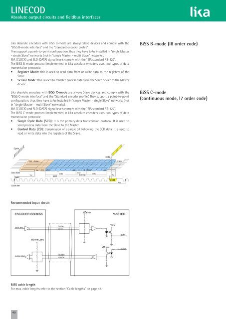
LINECOD Absolute output circuits and fieldbus interfaces Lika absolute encoders with BiSS B-mode are always Slave devices and comply with the “BiSS B-mode interface” and the “Standard encoder profile”. They support a point-to-point configuration, thus they have to be installed in “single Master – single Slave” networks (not in “single Master – multi Slave” networks). MA (CLOCK) and SLO (DATA) signal levels comply with the “EIA standard RS-422”. The BiSS B-mode protocol implemented in Lika absolute encoders uses two types of data transmission protocols: • Register Mode: this is used to read data from or write data to the registers of the Slave. • Sensor Mode: this is used to transfer process data from the Slave device to the Master device. Lika absolute encoders with BiSS C-mode are always Slave devices and comply with the “BiSS C-mode interface” and the “Standard encoder profile”. They support a point-to-point configuration, thus they have to be installed in “single Master – single Slave” networks (not in “single Master – multi Slave” networks). MA (CLOCK) and SLO (DATA) signal levels comply with the “EIA standard RS-422”. The BiSS C-mode protocol implemented in Lika absolute encoders uses two types of data transmission protocols: • Single Cycle Data (SCD): it is the primary data transmission protocol. It is used to send process data from the Slave to the Master. • Control Data (CD): transmission of a single bit following the SCD data. It is used to read or write data into the registers of the Slave. BiSS B-mode (I8 order code) BiSS C-mode (continuous mode, I7 order code) Recommended input circuit BiSS cable length For max. cable lengths refer to the section “Cable lengths” on page 44. 40
- Page 1: Smart encoders & actuators Incremen
- Page 4 and 5: An international family company, co
- Page 6 and 7: Quality policies at Lika Electronic
- Page 8 and 9: LINEPULS • LINECOD Technical info
- Page 10 and 11: LINEPULS • LINECOD Technical info
- Page 12 and 13: LINEPULS • LINECOD Technical info
- Page 14 and 15: LINEPULS • LINECOD Technical info
- Page 16 and 17: LINEPULS • LINECOD Technical info
- Page 18 and 19: LINEPULS • LINECOD Technical info
- Page 20 and 21: LINEPULS • LINECOD Technical info
- Page 22 and 23: LINEPULS • LINECOD Technical info
- Page 24 and 25: LINEPULS Output signals Most increm
- Page 26 and 27: LINEPULS Output signals SMEx1 linea
- Page 28 and 29: LINEPULS Output signals SMI2 Resolu
- Page 30 and 31: LINEPULS Output circuits Differenti
- Page 32 and 33: LINEPULS LINECOD Cable lenght We hi
- Page 34 and 35: LINECOD Output codes The absolute e
- Page 36 and 37: LINECOD Absolute output circuits an
- Page 40 and 41: LINECOD Additional functions for SS
- Page 42 and 43: LINECOD Additional functions for an
- Page 44 and 45: LINECOD Output circuits and fieldbu
- Page 46 and 47: POSICONTROL IF55 converter series I
- Page 48 and 49: LINECOD Output circuits and fieldbu
- Page 50 and 51: Index Overview catalogue page 52 LI
- Page 52 and 53: LINEPULS • LINECOD incremental &
- Page 54 and 55: ROTAPULS • ROTACOD bearingless en
- Page 56 and 57: ROTACOD absolute encoders for gener
- Page 58 and 59: ROTACOD absolute encoders with fiel
- Page 60 and 61: ROTAPULS • ROTACOD encoders with
- Page 62 and 63: ROTAPULS • ROTACOD specialty enco
- Page 64 and 65: DRIVECOD rotary actuators for forma
- Page 66 and 67: POSICONTROL interfaces, gateways &
- Page 68 and 69: www.lika.biz MT MTS Order code MT50
- Page 70 and 71: www.lika.biz SME51 LKM-1309/5 MT50
- Page 72 and 73: www.lika.biz SME52 LKM-1309/5 • L
- Page 74 and 75: www.lika.biz SME21 LKM-1309/2 MT20
- Page 76 and 77: www.lika.biz SME22 LKM-1309/2 • L
- Page 78 and 79: www.lika.biz SME11 LKM-1309/1 MT10
- Page 80 and 81: www.lika.biz SME12 LKM-1309/1 • L
- Page 82 and 83: www.lika.biz SMS11 • SMS21 LKM-13
- Page 84 and 85: www.lika.biz SMS12 LKM-1309/1 • L
- Page 86 and 87: www.lika.biz SMB2 • SMB5 MT20 •
<strong>LINECOD</strong><br />
Absolute output circuits and fieldbus <strong>in</strong>terfaces<br />
Lika absolute encoders with BiSS B-mode are always Slave devices and comply with the<br />
“BiSS B-mode <strong>in</strong>terface” and the “Standard encoder profile”.<br />
They support a po<strong>in</strong>t-to-po<strong>in</strong>t configuration, thus they have to be <strong>in</strong>stalled <strong>in</strong> “s<strong>in</strong>gle Master<br />
– s<strong>in</strong>gle Slave” networks (not <strong>in</strong> “s<strong>in</strong>gle Master – multi Slave” networks).<br />
MA (CLOCK) and SLO (DATA) signal levels comply with the “EIA standard RS-422”.<br />
The BiSS B-mode protocol implemented <strong>in</strong> Lika absolute encoders uses two types of data<br />
transmission protocols:<br />
• Register Mode: this is used to read data from or write data to the registers of the<br />
Slave.<br />
• Sensor Mode: this is used to transfer process data from the Slave device to the Master<br />
device.<br />
Lika absolute encoders with BiSS C-mode are always Slave devices and comply with the<br />
“BiSS C-mode <strong>in</strong>terface” and the “Standard encoder profile”. They support a po<strong>in</strong>t-to-po<strong>in</strong>t<br />
configuration, thus they have to be <strong>in</strong>stalled <strong>in</strong> “s<strong>in</strong>gle Master – s<strong>in</strong>gle Slave” networks (not<br />
<strong>in</strong> “s<strong>in</strong>gle Master – multi Slave” networks).<br />
MA (CLOCK) and SLO (DATA) signal levels comply with the “EIA standard RS-422”.<br />
The BiSS C-mode protocol implemented <strong>in</strong> Lika absolute encoders uses two types of data<br />
transmission protocols:<br />
• S<strong>in</strong>gle Cycle Data (SCD): it is the primary data transmission protocol. It is used to<br />
send process data from the Slave to the Master.<br />
• Control Data (CD): transmission of a s<strong>in</strong>gle bit follow<strong>in</strong>g the SCD data. It is used to<br />
read or write data <strong>in</strong>to the registers of the Slave.<br />
BiSS B-mode (I8 order code)<br />
BiSS C-mode<br />
(cont<strong>in</strong>uous mode, I7 order code)<br />
Recommended <strong>in</strong>put circuit<br />
BiSS cable length<br />
For max. cable lengths refer to the section “Cable lengths” on page 44.<br />
40


