LINEPULS & LINECOD catalogue 2016 in English
Lika Electronic incremental and absolute linear encoders catalogue 2016 in English Our new linear encoders catalogue is out now, and features many innovative new products and up-to-date information. The catalogue is expressly designed to set out the comprehensive range of incremental & absolute linear encoders from Lika Electronic. Check it out, it is completely renewed! Make sure you don’t miss out on a copy, download the pdf file from our web site or request your hard copy now! We have also got an interactive digital version in the works that shall be released soon!
Lika Electronic incremental and absolute linear encoders catalogue 2016 in English
Our new linear encoders catalogue is out now, and features many innovative new products and up-to-date information. The catalogue is expressly designed to set out the comprehensive range of incremental & absolute linear encoders from Lika Electronic. Check it out, it is completely renewed!
Make sure you don’t miss out on a copy, download the pdf file from our web site or request your hard copy now!
We have also got an interactive digital version in the works that shall be released soon!

Create successful ePaper yourself
Turn your PDF publications into a flip-book with our unique Google optimized e-Paper software.
<strong>LINECOD</strong><br />
Absolute output circuits and fieldbus <strong>in</strong>terfaces<br />
The absolute position <strong>in</strong>formation can be provided to the follow<strong>in</strong>g control via a wide variety<br />
of output circuits (<strong>in</strong>terfaces).<br />
Typically, we can dist<strong>in</strong>guish between electrical <strong>in</strong>terfaces (serial and analogue <strong>in</strong>terfaces)<br />
and fieldbus <strong>in</strong>terfaces.<br />
The absolute l<strong>in</strong>ear encoders are customarily fitted with serial (SSI, BiSS, RS-485) output<br />
circuits, the analogue circuit is more seldom used. The electrical <strong>in</strong>terfaces are simple, costeffective<br />
and easily fulfil the requirements of most <strong>in</strong>dustrial applications. Nevertheless <strong>in</strong><br />
the last years fieldbus <strong>in</strong>terfaces are rapidly ga<strong>in</strong><strong>in</strong>g ground worldwide because of their<br />
compatibility <strong>in</strong> more complex <strong>in</strong>stallations.<br />
Fieldbus technology <strong>in</strong> fact permits to improve performances thanks to complete device<br />
<strong>in</strong>terface (bi-directional data transmission, enhanced programmability, diagnostic <strong>in</strong>formation,<br />
etc.), achieve communication transparency, simplify and standardize <strong>in</strong>stallations<br />
allow<strong>in</strong>g several devices to be simply connected <strong>in</strong> the same network.<br />
In addition the use of standardised bus cables provides a simplified and safe connectivity<br />
thus sav<strong>in</strong>g time and money whilst reduc<strong>in</strong>g the risk of errors.<br />
To meet the <strong>in</strong>dustry's request for fieldbus and Ethernet networks and communication<br />
protocols, Lika Electronic has designed the range of IF55 gateways. They are specifically<br />
eng<strong>in</strong>eered to <strong>in</strong>terface SSI serial encoders and <strong>in</strong>tegrate them easily <strong>in</strong>to conventional<br />
fieldbus and <strong>in</strong>dustrial Ethernet networks.<br />
For complete <strong>in</strong>formation please refer to the section “IF55 converter series” on page 47.<br />
SSI (the acronym for Synchronous Serial Interface) is a synchronous po<strong>in</strong>t-to-po<strong>in</strong>t serial<br />
<strong>in</strong>terface eng<strong>in</strong>eered for unidirectional data transmission between one Master<br />
and one Slave. Developed <strong>in</strong> the first eighties of the last century, it is based on the RS-422<br />
serial standard. Its most peculiar feature is that data transmission is achieved by synchroniz<strong>in</strong>g<br />
both the Master and the Slave devices to a common clock signal generated by the<br />
controller; <strong>in</strong> this way the output <strong>in</strong>formation is clocked out at each controller request.<br />
Furthermore only two pairs of twisted wires are used for data and clock signals, thus a sixwire<br />
cable is required.<br />
The ma<strong>in</strong> advantages <strong>in</strong> comparison with compet<strong>in</strong>g parallel or asynchronous data transmissions<br />
are:<br />
• less conductors are required for transmission;<br />
• less electronic components;<br />
• possibility of <strong>in</strong>sulat<strong>in</strong>g the circuits galvanically by means of optocouplers;<br />
• high data transmission frequency;<br />
• hardware <strong>in</strong>terface <strong>in</strong>dependent of the resolution of the absolute encoder.<br />
Furthermore the differential transmission <strong>in</strong>creases the noise immunity and decreases the<br />
noise emissions. It allows multiplex<strong>in</strong>g from several encoders, thus process controls are more<br />
reliable with simplified l<strong>in</strong>e design and easier data management.<br />
In addition, SSI encoders can be easily <strong>in</strong>tegrated <strong>in</strong>to conventional fieldbus or <strong>in</strong>dustrial<br />
Ethernet networks us<strong>in</strong>g IF55 converters (see on page 47).<br />
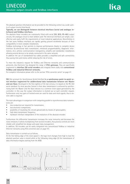
Data transmission is carried out as follows.<br />
At the first fall<strong>in</strong>g edge of the clock signal (1, the logic level changes from high to low) the<br />
absolute position value is stored while at the follow<strong>in</strong>g ris<strong>in</strong>g edge (2) the transmission of<br />
data <strong>in</strong>formation beg<strong>in</strong>s start<strong>in</strong>g from the MSB.<br />
36