LINEPULS & LINECOD catalogue 2016 in English
Lika Electronic incremental and absolute linear encoders catalogue 2016 in English
Our new linear encoders catalogue is out now, and features many innovative new products and up-to-date information. The catalogue is expressly designed to set out the comprehensive range of incremental & absolute linear encoders from Lika Electronic. Check it out, it is completely renewed!
Make sure you don’t miss out on a copy, download the pdf file from our web site or request your hard copy now!
We have also got an interactive digital version in the works that shall be released soon!
LINEPULS LINECOD Cable lenght We highly recommend the cable lengths reported in the following tables to be fulfilled strictly. Please note that data listed below may vary due to the following factors: • the supply voltage of the encoder; • the quality of the cable; • the electrical noise coming from the ground connection; • the features of the controller connected to the encoder; • the ambient temperature. Cable lengths For the afore-mentioned reasons the recommended cable lengths could be shorter depending on each specific application. Maximum cable lengths in relation to frequencies Output circuit Y Push-Pull (AB0 signals) Max. cable length m / ft Max. counting frequency 2 m / 7 ft 2 MHz 5 m / 17 ft 1 MHz 10 m / 35 ft 400 kHz 20 m / 65 ft 200 kHz 30 m / 100 ft 100 kHz Output circuit YC Push-Pull (AB0, /AB0 signals) H, AB0 /AB0 PP/LD universal circuit Max. cable length m / ft Max. counting frequency 6 m / 20 ft 2 MHz 15 m / 50 ft 1 MHz 60 m / 200 ft 400 kHz 120 m / 395 ft 200 kHz 180 m / 590 ft 100 kHz Output circuit L Line Driver (RS422) Max. cable length m / ft Max. counting frequency 10 m / 35 ft 2 MHz 25 m / 85 ft 1 MHz 50 m / 165 ft 400 kHz 100 m / 330 ft 200 kHz 150 m / 495 ft 100 kHz At ambient temperature (23°C) Max. counting frequency = frequency A, B x4 Please always consider also the set minimum edge distance and the maximum speed allowed (see the values in the tables under the “Edge distance” section on page 27). Line Driver: please always consider the voltage drop over wires. Refer also to the “Cable specifications” on page 118 to estimate the voltage drop. Please note that the higher the resolution and the maximum travel speed of the encoder, the higher the counting frequency. There is a straight relation between the counting frequency and the signal distortion. The longer is the cable in fact, the greater is its capacitance; and the capacitance affects the signal quality causing the higher frequencies to be “filtered” so distorting the signal. Please always refer to the maximum counting frequency value indicated in the product datasheet; consider also the relation between the counting frequency and the maximum permissible speed indicated in the tables on page 28. Please always check both the max. permissible speed and the counting frequency in order to be sure that they comply with the characteristics of your mechanical system and the following electronics and with the run of the cables. For the max. permissible speed and counting frequency refer to the tables in the section “Edge distance” on page 27. 33
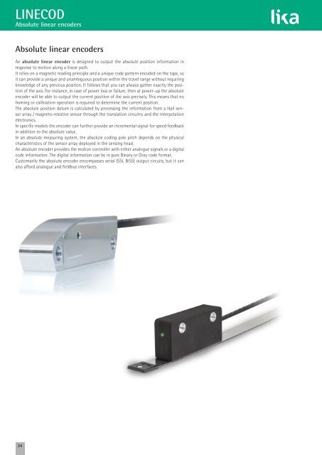
LINECOD Absolute linear encoders Absolute linear encoders An absolute linear encoder is designed to output the absolute position information in response to motion along a linear path. It relies on a magnetic reading principle and a unique code pattern encoded on the tape, so it can provide a unique and unambiguous position within the travel range without requiring knowledge of any previous position. It follows that you can always gather exactly the position of the axis. For instance, in case of power loss or failure, then at power-up the absolute encoder will be able to output the current position of the axis precisely. This means that no homing or calibration operation is required to determine the current position. The absolute position datum is calculated by processing the information from a Hall sensor array / magneto-resistive sensor through the translation circuitry and the interpolation electronics. In specific models the encoder can further provide an incremental signal for speed feedback in addition to the absolute value. In an absolute measuring system, the absolute coding pole pitch depends on the physical characteristics of the sensor array deployed in the sensing head. An absolute encoder provides the motion controller with either analogue signals or a digital code information. The digital information can be in pure Binary or Gray code format. Customarily the absolute encoder encompasses serial (SSI, BiSS) output circuits, but it can also afford analogue and fieldbus interfaces. 34
- Page 1: Smart encoders & actuators Incremen
- Page 4 and 5: An international family company, co
- Page 6 and 7: Quality policies at Lika Electronic
- Page 8 and 9: LINEPULS • LINECOD Technical info
- Page 10 and 11: LINEPULS • LINECOD Technical info
- Page 12 and 13: LINEPULS • LINECOD Technical info
- Page 14 and 15: LINEPULS • LINECOD Technical info
- Page 16 and 17: LINEPULS • LINECOD Technical info
- Page 18 and 19: LINEPULS • LINECOD Technical info
- Page 20 and 21: LINEPULS • LINECOD Technical info
- Page 22 and 23: LINEPULS • LINECOD Technical info
- Page 24 and 25: LINEPULS Output signals Most increm
- Page 26 and 27: LINEPULS Output signals SMEx1 linea
- Page 28 and 29: LINEPULS Output signals SMI2 Resolu
- Page 30 and 31: LINEPULS Output circuits Differenti
- Page 34 and 35: LINECOD Output codes The absolute e
- Page 36 and 37: LINECOD Absolute output circuits an
- Page 38 and 39: LINECOD Absolute output circuits an
- Page 40 and 41: LINECOD Additional functions for SS
- Page 42 and 43: LINECOD Additional functions for an
- Page 44 and 45: LINECOD Output circuits and fieldbu
- Page 46 and 47: POSICONTROL IF55 converter series I
- Page 48 and 49: LINECOD Output circuits and fieldbu
- Page 50 and 51: Index Overview catalogue page 52 LI
- Page 52 and 53: LINEPULS • LINECOD incremental &
- Page 54 and 55: ROTAPULS • ROTACOD bearingless en
- Page 56 and 57: ROTACOD absolute encoders for gener
- Page 58 and 59: ROTACOD absolute encoders with fiel
- Page 60 and 61: ROTAPULS • ROTACOD encoders with
- Page 62 and 63: ROTAPULS • ROTACOD specialty enco
- Page 64 and 65: DRIVECOD rotary actuators for forma
- Page 66 and 67: POSICONTROL interfaces, gateways &
- Page 68 and 69: www.lika.biz MT MTS Order code MT50
- Page 70 and 71: www.lika.biz SME51 LKM-1309/5 MT50
- Page 72 and 73: www.lika.biz SME52 LKM-1309/5 • L
- Page 74 and 75: www.lika.biz SME21 LKM-1309/2 MT20
- Page 76 and 77: www.lika.biz SME22 LKM-1309/2 • L
- Page 78 and 79: www.lika.biz SME11 LKM-1309/1 MT10
- Page 80 and 81: www.lika.biz SME12 LKM-1309/1 • L
<strong>LINECOD</strong><br />
Absolute l<strong>in</strong>ear encoders<br />
Absolute l<strong>in</strong>ear encoders<br />
An absolute l<strong>in</strong>ear encoder is designed to output the absolute position <strong>in</strong>formation <strong>in</strong><br />
response to motion along a l<strong>in</strong>ear path.<br />
It relies on a magnetic read<strong>in</strong>g pr<strong>in</strong>ciple and a unique code pattern encoded on the tape, so<br />
it can provide a unique and unambiguous position with<strong>in</strong> the travel range without requir<strong>in</strong>g<br />
knowledge of any previous position. It follows that you can always gather exactly the position<br />
of the axis. For <strong>in</strong>stance, <strong>in</strong> case of power loss or failure, then at power-up the absolute<br />
encoder will be able to output the current position of the axis precisely. This means that no<br />
hom<strong>in</strong>g or calibration operation is required to determ<strong>in</strong>e the current position.<br />
The absolute position datum is calculated by process<strong>in</strong>g the <strong>in</strong>formation from a Hall sensor<br />
array / magneto-resistive sensor through the translation circuitry and the <strong>in</strong>terpolation<br />
electronics.<br />
In specific models the encoder can further provide an <strong>in</strong>cremental signal for speed feedback<br />
<strong>in</strong> addition to the absolute value.<br />
In an absolute measur<strong>in</strong>g system, the absolute cod<strong>in</strong>g pole pitch depends on the physical<br />
characteristics of the sensor array deployed <strong>in</strong> the sens<strong>in</strong>g head.<br />
An absolute encoder provides the motion controller with either analogue signals or a digital<br />
code <strong>in</strong>formation. The digital <strong>in</strong>formation can be <strong>in</strong> pure B<strong>in</strong>ary or Gray code format.<br />
Customarily the absolute encoder encompasses serial (SSI, BiSS) output circuits, but it can<br />
also afford analogue and fieldbus <strong>in</strong>terfaces.<br />
34


