LINEPULS & LINECOD catalogue 2016 in English
Lika Electronic incremental and absolute linear encoders catalogue 2016 in English Our new linear encoders catalogue is out now, and features many innovative new products and up-to-date information. The catalogue is expressly designed to set out the comprehensive range of incremental & absolute linear encoders from Lika Electronic. Check it out, it is completely renewed! Make sure you don’t miss out on a copy, download the pdf file from our web site or request your hard copy now! We have also got an interactive digital version in the works that shall be released soon!
Lika Electronic incremental and absolute linear encoders catalogue 2016 in English
Our new linear encoders catalogue is out now, and features many innovative new products and up-to-date information. The catalogue is expressly designed to set out the comprehensive range of incremental & absolute linear encoders from Lika Electronic. Check it out, it is completely renewed!
Make sure you don’t miss out on a copy, download the pdf file from our web site or request your hard copy now!
We have also got an interactive digital version in the works that shall be released soon!

Create successful ePaper yourself
Turn your PDF publications into a flip-book with our unique Google optimized e-Paper software.
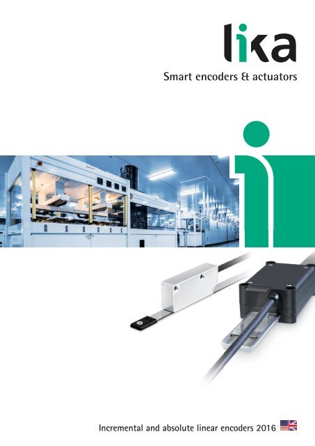
Smart encoders & actuators<br />
Incremental and absolute l<strong>in</strong>ear encoders <strong>2016</strong>
ROTAPULS<br />
Incremental rotary encoders<br />
ROTACOD<br />
Absolute rotary & Fieldbus encoders<br />
ROTAMAG<br />
Rotary Magnetic encoder &<br />
Encoder modules<br />
<strong>LINEPULS</strong> – <strong>LINECOD</strong><br />
L<strong>in</strong>ear Absolute & Incremental encoders<br />
DRAW-WIRE<br />
Draw-wire encoders & potentiometers<br />
COUPLINGS<br />
Flexible & Transmission coupl<strong>in</strong>gs<br />
POSICONTROL<br />
Displays & Signal converters<br />
Encoder Interfaces<br />
DRIVECOD<br />
Rotary Actuators & Position<strong>in</strong>g units<br />
1982<br />
Lika Electronic<br />
founded <strong>in</strong> Schio (VI).<br />
1986<br />
Manufactur<strong>in</strong>g of<br />
absolute encoders with<br />
<strong>in</strong>tegrated display and<br />
<strong>in</strong>cremental encoders<br />
for the Italian market.<br />
1993<br />
Lika Electronic is the<br />
first company <strong>in</strong> Italy<br />
to offer a complete<br />
portfolio of encoders<br />
<strong>in</strong> the 58 mm diam.<br />
range.<br />
1997<br />
Lika is first certified<br />
to ISO 9001:1994.<br />
1982 1986 1990 1995<br />
4<br />
1983<br />
Lika numbers 8<br />
customers.<br />
1985<br />
Lika starts the<br />
production of<br />
absolute encoders<br />
for the German<br />
market.<br />
1987<br />
Lika produces a 50 mm<br />
diameter m<strong>in</strong>iature<br />
encoder, the smallest<br />
absolute encoder <strong>in</strong><br />
Europe.<br />
1995<br />
The 100,000th<br />
encoder rolled off the<br />
production l<strong>in</strong>e.<br />
1996<br />
ROTACAM ASR58 is the<br />
first absolute encoder<br />
fitted with <strong>in</strong>tegrated<br />
cam programmer.
An <strong>in</strong>ternational family company,<br />
corporate profile<br />
Lika Electronic stands for encoders and position measur<strong>in</strong>g<br />
systems. S<strong>in</strong>ce its <strong>in</strong>ception <strong>in</strong> 1982, Lika Electronic<br />
develops and manufactures <strong>in</strong>cremental and absolute,<br />
optical and magnetic, rotary and l<strong>in</strong>ear encoders, <strong>in</strong>cremental<br />
& absolute sensors, l<strong>in</strong>ear and rotary <strong>in</strong>cremental<br />
& absolute magnetic measurement systems, rotary actuators,<br />
displays, signal converters and encoder <strong>in</strong>terfaces.<br />
Start<strong>in</strong>g as a family-owned bus<strong>in</strong>ess, thanks to its technical<br />
competence and comprehensive know-how <strong>in</strong> the<br />
automation <strong>in</strong>dustry along with the high quality standards<br />
and the skill <strong>in</strong> provid<strong>in</strong>g<br />
solutions that target specific<br />
customer needs, over the years<br />
Lika Electronic has grown<br />
becom<strong>in</strong>g a forward th<strong>in</strong>k<strong>in</strong>g<br />
<strong>in</strong>novative and global company<br />
and has become one of<br />
the lead<strong>in</strong>g manufacturers of<br />
optical encoders and magnetic<br />
measurement systems <strong>in</strong> Europe<br />
and worldwide.<br />
Many key features <strong>in</strong>clude the<br />
extensive technical eng<strong>in</strong>eer<strong>in</strong>g<br />
skills , <strong>in</strong>-depth knowledge and<br />
expertise <strong>in</strong> digital and analogical<br />
electronic design as well<br />
as the proven daily practice <strong>in</strong><br />
co-operation with universities,<br />
research <strong>in</strong>stitutions and<br />
customers <strong>in</strong> order to develop and provide advanced<br />
electronic equipment and high-tech materials &<br />
devices tailored to specific customer and market<br />
requirements. Moreover software development and<br />
mechanical & optical components design are entirely<br />
performed with<strong>in</strong> the company. Often production mach<strong>in</strong>ery<br />
and tools are often eng<strong>in</strong>eered and built <strong>in</strong>ternally<br />
to satisfy specific needs and performances.<br />
Every day Lika Electronic is committed to be<strong>in</strong>g a step<br />
ahead and always at the forefront of <strong>in</strong>novation, look<strong>in</strong>g<br />
to the future with the enthusiasm that steers the<br />
company towards new opportunities without giv<strong>in</strong>g up<br />
the strength of be<strong>in</strong>g an <strong>in</strong>ternational family company.<br />
Lika Electronic is certified for compliance with ISO<br />
9001:2000 quality management system and is now committed<br />
to adopt an environmental management system<br />
comply<strong>in</strong>g with ISO 14001:2004 requirements. All Lika’s<br />
products are designed and manufactured to fully meet<br />
the requirements of CE, RoHS and REACH directives, most<br />
of them are UL and CSA compliant too. ATEX certified<br />
solutions suitable to be <strong>in</strong>tegrated <strong>in</strong>to potential explosive<br />
environments and hazardous areas are also available.<br />
Global presence, make us closer to the<br />
customer<br />
The Rosetta space mission<br />
Every day, everywhere Lika<br />
Electronic works <strong>in</strong> close contact<br />
with its customers to build<br />
strong, long-last<strong>in</strong>g relationships<br />
and support them at<br />
all times <strong>in</strong> each day-to-day<br />
requirement. Lika’s actions focus<br />
on customers’ needs with<br />
daily challenges to develop<br />
reliable and cutt<strong>in</strong>g edge solutions<br />
Cont<strong>in</strong>uous <strong>in</strong>novation,<br />
outstand<strong>in</strong>g expertise, overall<br />
quality, prompt action and<br />
maximum flexibility are the<br />
fundamental values that Lika<br />
Electronic is truly proud of<br />
offer<strong>in</strong>g its customers when<br />
work<strong>in</strong>g together.<br />
Lika is proud to be part of the <strong>in</strong>ternational team of<br />
companies that, under the guide of the European<br />
Space Agency (ESA) has allowed to achieve this<br />
historic result. Visit our website for full <strong>in</strong>formation.<br />
Lika Electronic operates all over the world provid<strong>in</strong>g a<br />
widespread and efficient global distribution network,<br />
offer<strong>in</strong>g unrivalled technical support and excellent<br />
customer service. At the present time the export share<br />
is approximately 60% of the turnover <strong>in</strong> more than 50<br />
countries.<br />
2000<br />
ROSETTA space probe<br />
project gets under<br />
way <strong>in</strong> co-operation<br />
with CISAS.<br />
2002<br />
Production <strong>in</strong> antistatic<br />
environment (ESD).<br />
DRIVECOD & POSICONTROL<br />
product ranges are launched<br />
<strong>in</strong> the market.<br />
2007<br />
Lika Electronic<br />
celebrates its 25th<br />
anniversary.<br />
2012<br />
30th anniversary:<br />
“30 new products for<br />
our 30 years” event<br />
launched.<br />
2015<br />
Certificate<br />
ISO 14001:2004<br />
2012<br />
2000 2004 2008 2012 2015<br />
1998<br />
First 16-bit resolution<br />
s<strong>in</strong>gle-turn absolute<br />
encoder eng<strong>in</strong>eered for<br />
<strong>in</strong>stallation <strong>in</strong> aerostatic<br />
probes developed by<br />
Florence University.<br />
2004<br />
Arianne 5 rocket<br />
successfully<br />
launched: Rosetta<br />
probe fits Lika<br />
encoders.<br />
2008<br />
ALMA project: giant<br />
array of 12-m<br />
radio telescopes<br />
equipped with<br />
special custom-made<br />
Lika encoders.<br />
2010<br />
Lika <strong>in</strong>troduces the<br />
<strong>in</strong>novative range of<br />
heavy-duty products<br />
dedicated to steel<br />
& iron <strong>in</strong>dustry and<br />
w<strong>in</strong>d mills.<br />
2013<br />
Lika South East Asia<br />
founded <strong>in</strong> Thailand.<br />
5
Environmental policies at Lika Electronic<br />
Besides a daily <strong>in</strong>vestment <strong>in</strong> materials research, electronics improvement and software development, day after<br />
day also environmental values have become an unavoidable commitment <strong>in</strong> each choice and strategy of the<br />
company. For this purpose, even though discretionary, conscious about the importance of the human health,<br />
the environmental protection and the preservation of natural resources, s<strong>in</strong>ce 2006 Lika Electronic has decided<br />
to fully comply with the directive 2002/95/EC, usually referred to as RoHS, i.e. Restriction of Hazardous Substances<br />
Directive (it has been replaced by the new “RoHS2” Directive 2011/65/EU recently).<br />
Two years later Lika Electronic has adhered to str<strong>in</strong>gent directive 1907/2006/EC, usually referred to as REACH,<br />
bann<strong>in</strong>g the chemical substances reported <strong>in</strong> ECHA’s Candidate List and <strong>in</strong> authorized list. Now Lika Electronic<br />
is committed to adopt an environmental management system comply<strong>in</strong>g with ISO 14001:2004 requirements<br />
<strong>in</strong> order to promote a responsible environmental policy among employees, suppliers and customers as well.<br />
Dedication to corporate responsibility has led the company to implement a real “green” <strong>in</strong>vestment for environmental<br />
susta<strong>in</strong>ability: Lika Electronic is equipped with a photovoltaic system consist<strong>in</strong>g of 260 PV modules<br />
for a maximum power output of about 65 kW which prevents the emission of approximately 40 tonnes of CO 2<br />
per year.<br />
Express service<br />
Lika Electronic provides high flexibility and faster action as all design and production processes are carried out <strong>in</strong>-house.<br />
For this reason we are able to translate any needs <strong>in</strong>to customized solutions <strong>in</strong> very short time. Fast manufactur<strong>in</strong>g service is available and <strong>in</strong>tended to<br />
ensure production with<strong>in</strong> three work<strong>in</strong>g days only. The service is subject to availability of all parts at our premises.<br />
Customer service & assistance<br />
Production and manufactur<strong>in</strong>g processes from design to after-sales are constantly monitored and improved<br />
to ensure optimized, fast, resilient and cost-effective service. Thus you can trust <strong>in</strong> a dependable<br />
and on-time service -from production to delivery. Furthermore Lika Electronic is able to translate the<br />
customers’ specific requirements and needs <strong>in</strong>to customized solutions <strong>in</strong> very short time, both for small<br />
and large batches. A repairs workshop also operates with<strong>in</strong> Lika’s facilities where expert and thorough<br />
personnel provide fast and effective repair service and guarantee reduced times and costs. Lika’s team<br />
is dynamic, professional and customer-focused and has relevant experience and technical competence.<br />
Whether you need troubleshoot<strong>in</strong>g assistance or bus<strong>in</strong>ess advice we provide outstand<strong>in</strong>g and responsive<br />
technical support and excellent customer service. <strong>English</strong>, Italian, German, French and Spanish are<br />
fluently spoken. Offices and phone l<strong>in</strong>es are open Monday to Friday 8am – 5pm CET.<br />
Catalogues, user manuals and website<br />
As a part of Lika’s ongo<strong>in</strong>g commitment to provide the highest level of<br />
support to make customers’ job easier, a full set of technical and commercial<br />
documentation is easily available <strong>in</strong> the Downloads section of our<br />
corporate website and upon request.<br />
Catalogues, brochures, datasheets, user’s manuals and <strong>in</strong>stallation guides<br />
are offered <strong>in</strong> the most common languages. The general <strong>catalogue</strong> is a<br />
hands-on reference guide useful to describe the whole products portfolio<br />
and is available <strong>in</strong> more than 10 languages.<br />
Series-specific and thematic <strong>catalogue</strong>s provide detailed product <strong>in</strong>formation<br />
and technical specifications that can help you always make the right<br />
choice.<br />
6
Quality policies at Lika Electronic<br />
Quality policy has always been of highest priority for Lika Electronic.<br />
Lika is every day committed to develop and manufacture products that are recognized by<br />
customers and the <strong>in</strong>dustry for their high quality and performances.<br />
Quality policy statement has been established s<strong>in</strong>ce 1997 when Lika Electronic was first<br />
certified to ISO 9001:1994. Nowadays Lika Electronic is certified to ISO 9001:2008<br />
compliant quality management system. It attests that Lika Electronic places the utmost<br />
importance <strong>in</strong> the quality, safety and reliability of its products and every day aims at ensur<strong>in</strong>g<br />
the full satisfaction of customer’s needs.<br />
This is achieved by cont<strong>in</strong>uously develop<strong>in</strong>g new products that implement the most advanced<br />
technologies and can easily meet customers and markets requirements; by enhanc<strong>in</strong>g<br />
both <strong>in</strong>ternal and suppliers’ processes for cont<strong>in</strong>ual improvement of the system and the<br />
assurance of conformity; and by always meet<strong>in</strong>g the regulations and comply<strong>in</strong>g early with<br />
future standards. All production and manufactur<strong>in</strong>g processes as well as company management<br />
activities are <strong>in</strong>volved <strong>in</strong> quality assurance and enhancement: from purchas<strong>in</strong>g to<br />
goods receipt, from manufactur<strong>in</strong>g to technical, from sales to account departments.<br />
With the same purpose and even if not b<strong>in</strong>d<strong>in</strong>g with this directive, Lika Electronic is committed<br />
to comply with Directive 1907/2006/EC, usually referred to as REACH. REACH is<br />
the European Community Regulation on chemicals and their safe use. It deals with the<br />
Registration, Evaluation, Authorization and Restriction of Chemical substances. The law entered<br />
<strong>in</strong>to force on 1 st June 2007.<br />
The aim of REACH is to improve the protection of human health and the environment<br />
through the better and earlier identification of the <strong>in</strong>tr<strong>in</strong>sic properties of chemical substances<br />
and progressive substitution of the most dangerous chemicals when suitable alternatives<br />
have been identified.<br />
All Lika encoders are CE compliant and fully meet the requirements of the EMC European<br />
Directives as well as the recent Directive 2011/65/EU (RoHS2).<br />
All Lika encoders comply with the Directive 2002/95/EC, usually referred to as RoHS, i.e.<br />
Restriction of Hazardous Substances Directive, s<strong>in</strong>ce 2006.<br />
The RoHS directive aims to restrict certa<strong>in</strong> dangerous substances commonly used <strong>in</strong> electronic<br />
equipment.<br />
Any RoHS compliant component is attested to be free from the presence of Lead (Pb), Cadmium<br />
(Cd), Mercury (Hg), Hexavalent chromium (Hex-Cr), Polybrom<strong>in</strong>ated biphenyls (PBB)<br />
and Polybrom<strong>in</strong>ated diphenyl ethers (PBDE).<br />
This means that <strong>in</strong> all Lika products maximum concentrations of the afore-mentioned substances<br />
are under the restrictive limits permitted by this Directive.<br />
July 2011 the new Directive 2011/65/EU, sometimes referred to as RoHS2, was published by<br />
the European Commission. The ma<strong>in</strong> po<strong>in</strong>t to consider is that the RoHS directive is now a<br />
CE-mark<strong>in</strong>g Directive. This means that compliance with RoHS Directive is required <strong>in</strong> order<br />
to place the CE mark on any product.<br />
Lika Electronic declares that all products are here and now RoHS2 compliant and therefore<br />
they are allowed to bear the CE mark.<br />
7
WEEE and end-of-life disposal <strong>in</strong>formation<br />
Directive 2012/19/UE (as previous 2002/96/EC) is <strong>in</strong>tended, as a first priority, to prevent waste electric<br />
and electronic equipment (hence the acronym WEEE) from be<strong>in</strong>g <strong>in</strong>troduced <strong>in</strong>to the unsorted waste<br />
stream; and <strong>in</strong> addition to promote reuse, recycl<strong>in</strong>g and other forms of recovery of such wastes so as<br />
to reduce the disposal of waste.<br />
Furthermore it encourages the “ecological” design and production of electrical and electronic<br />
equipment which take <strong>in</strong>to account and facilitate dismantl<strong>in</strong>g and recovery, <strong>in</strong> particular the re-use<br />
and recycl<strong>in</strong>g of WEEE, their components and materials.<br />
Extended producer and user responsibility for separate collection is the precondition to ensure specific<br />
treatment and recycl<strong>in</strong>g of WEEE and is necessary to achieve the chosen level of protection of<br />
human health and the environment.<br />
Products manufactured by Lika Electronic are not covered by WEEE directive currently as they do not<br />
fall under the categories com<strong>in</strong>g with<strong>in</strong> the scope of the Directive.<br />
WEEE directive applies to standalone products; our products cannot function entirely on their own,<br />
they are always <strong>in</strong>tegrated <strong>in</strong>to larger systems and come as part of complex equipment. Anyway,<br />
electric and electronic equipment may conta<strong>in</strong> materials, components and substances which can be<br />
dangerous to the environment and harmful to human health if not disposed properly.<br />
So you should not dispose of electrical and electronic equipment as unsorted municipal waste.<br />
Please we advise you to dispose of waste so as to reduce environmental impact and <strong>in</strong>crease reuse,<br />
recycl<strong>in</strong>g and recover<strong>in</strong>g of WEEE.<br />
For this reason the symbol of the crossed-out wheelie b<strong>in</strong> appears <strong>in</strong> the documentation of all our<br />
products.<br />
For customers who wish to send us back Lika products at the end of their life, we are will<strong>in</strong>g to recycle<br />
and dispose of them <strong>in</strong> compliance with Directives and regulations <strong>in</strong> force.<br />
Product label<br />
Each device is fitted with its own product label applied to the enclosure.<br />
All important data such as product name, order code, serial number, … is pr<strong>in</strong>ted on the label.<br />
Please have this data to hand when you call to help us deal with your enquiry quicker.<br />
The label is applied at the end of the manufactur<strong>in</strong>g process and after pass<strong>in</strong>g all conformance and<br />
quality tests. Each device is <strong>in</strong>dividually checked and tested by expert and thorough personnel hav<strong>in</strong>g<br />
relevant experience and technical competence.<br />
Thus the label certifies that the product has been subjected to rigorous test<strong>in</strong>g throughout its development<br />
and production <strong>in</strong> order to assess its safety, performance and conformity to Lika’s quality<br />
standards.<br />
8
<strong>LINEPULS</strong> • <strong>LINECOD</strong><br />
Technical <strong>in</strong>formation<br />
L<strong>in</strong>ear encoders<br />
L<strong>in</strong>ear encoders are measur<strong>in</strong>g systems that<br />
generate signals <strong>in</strong> response to a l<strong>in</strong>ear motion.<br />
They are specifically designed to convert a l<strong>in</strong>ear<br />
motion <strong>in</strong>to either analogue/digital electrical signals<br />
or a digital code <strong>in</strong> order to determ<strong>in</strong>e the<br />
change <strong>in</strong> position.<br />
They basically consist of a readhead (oxtherwise<br />
referred to as sens<strong>in</strong>g head here<strong>in</strong>after) and an<br />
active measurement scale, namely a magnetic<br />
tape (sometimes a passive measurement tape could be used <strong>in</strong> specific applications -for <strong>in</strong>stance a ferromagnetic<br />
toothed structure. For any <strong>in</strong>formation on such dedicated measur<strong>in</strong>g systems see on page 23).<br />
The readhead encompasses MR magneto-resistive sensors/Hall sensors (see on page 12) and the convert<strong>in</strong>g/<br />
translation circuitry (see on page 12). The readhead is paired with a magnetic tape that encodes the <strong>in</strong>cremental/<br />
absolute position <strong>in</strong>formation.<br />
When the sens<strong>in</strong>g head is moved along the tape without contact, it reads the sequence of North-South poles and<br />
converts the encoded datum position <strong>in</strong>to an analogue/digital signal or a digital code.<br />
Thus the l<strong>in</strong>ear encoder is able to provide the motion controller with <strong>in</strong>formation concern<strong>in</strong>g travel, position,<br />
displacement, direction, velocity and acceleration.<br />
L<strong>in</strong>ear encoders offer great advantages. The magnetic sens<strong>in</strong>g technology is non-contact and frictionless; the<br />
use of m<strong>in</strong>iaturized sensor modules and circuitries allow for very compact and slim enclosures; the operation<br />
without mobile mechanical elements m<strong>in</strong>imize the risks of errors and failures (no bear<strong>in</strong>gs are used!). In addition<br />
they can be easily protected aga<strong>in</strong>st contam<strong>in</strong>ants us<strong>in</strong>g methods such as tropicalization, conformal coat<strong>in</strong>g, encapsulat<strong>in</strong>g<br />
or varnish<strong>in</strong>g thus easily achiev<strong>in</strong>g the highest IP rat<strong>in</strong>gs (IP67 to IP69K).<br />
L<strong>in</strong>ear encoders from Lika Electronic have m<strong>in</strong>imal dimensions and provide high immunity to <strong>in</strong>terferences and<br />
most contam<strong>in</strong>ants. S<strong>in</strong>ce they detect change <strong>in</strong> the magnetic field, they are <strong>in</strong>sensitive to external <strong>in</strong>fluences such<br />
as light, dust, moisture, oil, grease, water jets and a variety of chemical agents.<br />
They work without contact and ensure virtually wear & ma<strong>in</strong>tenance-free operation.<br />
Furthermore they are able to offer high reliability, endur<strong>in</strong>g service and long operat<strong>in</strong>g life even <strong>in</strong> demand<strong>in</strong>g<br />
conditions and under dirt, shocks, vibrations, temperature fluctuations and significant mechanical stresses.<br />
L<strong>in</strong>ear sensors are claimed to reliably operate <strong>in</strong> the most aggressive and harshest <strong>in</strong>dustrial environments<br />
and ideally suited for applications where small size, high robustness and f<strong>in</strong>e resolution are mandatory.<br />
Among the typical applications are:<br />
• motion systems, direct drives and l<strong>in</strong>ear motors;<br />
• electronic and semiconductors assembly systems, PCB assembly equipment and wire bonders;<br />
• product handl<strong>in</strong>g equipment, robotics, pick-and-place l<strong>in</strong>es;<br />
• mach<strong>in</strong><strong>in</strong>g tools (bor<strong>in</strong>g mach<strong>in</strong>es, lathes, cutt<strong>in</strong>g and bend<strong>in</strong>g mach<strong>in</strong>es …);<br />
• telescopic systems and hydraulic pistons (outriggers, stabiliz<strong>in</strong>g slides, telescopic cranes, booms of mobile<br />
equipment …);<br />
• valve actuators;<br />
• utility vehicles and <strong>in</strong>dustrial trucks;<br />
• forklifts, scissor lifts and load<strong>in</strong>g platforms;<br />
• medical technology applications such as exam<strong>in</strong>ation tables, X-ray mach<strong>in</strong>es, dentist's chairs and laboratory<br />
test<strong>in</strong>g devices;<br />
• electro-medical and metrology <strong>in</strong>struments;<br />
• pr<strong>in</strong>t<strong>in</strong>g mach<strong>in</strong>es, presses and convert<strong>in</strong>g mach<strong>in</strong>eries;<br />
• textile, wood, metal and stone work<strong>in</strong>g mach<strong>in</strong>eries.<br />
9
<strong>LINEPULS</strong> • <strong>LINECOD</strong><br />
Sottotitolo Technical <strong>in</strong>formation<br />
L<strong>in</strong>ear encoders can be <strong>in</strong>cremental or absolute.<br />
Incremental l<strong>in</strong>ear encoders produce square waves signals or s<strong>in</strong>usoidal signals and can<br />
provide travel, position and displacement <strong>in</strong>formation. Positional <strong>in</strong>formation is cyclical,<br />
thus relative and ambiguous; this means that you can gather whether the axis is mov<strong>in</strong>g<br />
and the direction of the movement; yet you cannot get <strong>in</strong>formation about its absolute position.<br />
To compensate for this glitch the hom<strong>in</strong>g operation is always required at the beg<strong>in</strong>n<strong>in</strong>g<br />
of the process to determ<strong>in</strong>e the absolute position of the system (detection of the zero po<strong>in</strong>t;<br />
then it requires count<strong>in</strong>g of cycles to ma<strong>in</strong>ta<strong>in</strong> absolute position with<strong>in</strong> the travel range).<br />
For such reason most <strong>in</strong>cremental l<strong>in</strong>ear encoders can produce Index and/or Reference mark<br />
pulses provid<strong>in</strong>g a datum position along the tape for use at power-up or follow<strong>in</strong>g a loss of<br />
power. For detailed <strong>in</strong>formation on <strong>in</strong>cremental l<strong>in</strong>ear encoders refer to page 24.<br />
Incremental encoder<br />
An absolute l<strong>in</strong>ear encoder is designed to output the absolute position <strong>in</strong>formation <strong>in</strong><br />
response to motion along a l<strong>in</strong>ear path. It relies on a unique code pattern encoded on the<br />
tape, so it can provide a unique and unambiguous position with<strong>in</strong> the travel range without<br />
requir<strong>in</strong>g knowledge of any previous position. The major advantage is that you can always<br />
gather exactly the position of the axis. For <strong>in</strong>stance, <strong>in</strong> case of power loss or failure, then at<br />
power-up the absolute encoder will be able to output the current position of the axis precisely.<br />
This means that no hom<strong>in</strong>g operation is required to determ<strong>in</strong>e the current position.<br />
An absolute encoder provides the motion controller with either analogue signals or a digital<br />
code <strong>in</strong>formation. The digital <strong>in</strong>formation can be <strong>in</strong> pure B<strong>in</strong>ary or Gray code format.<br />
Customarily the absolute encoder encompasses serial (SSI, BiSS) output circuits, but it can<br />
also afford analogue and fieldbus <strong>in</strong>terfaces.<br />
For detailed <strong>in</strong>formation on absolute l<strong>in</strong>ear encoders refer to page 34.<br />
Absolute encoder<br />
At a glance: L<strong>in</strong>ear Encoder typical features<br />
10
<strong>LINEPULS</strong> • <strong>LINECOD</strong><br />
Technical <strong>in</strong>formation<br />
www.lika.biz<br />
The magnetic tape is the carrier of the <strong>in</strong>cremental and absolute encoded position <strong>in</strong>formation.<br />
Magnetic tape<br />
It is primarily made up of a bonded ferrite material where the datum position is coded.<br />
Dur<strong>in</strong>g the encod<strong>in</strong>g process, the sensitive material is magnetized to obta<strong>in</strong> either a systematic<br />
sequence of North-South poles with alternat<strong>in</strong>g magnetic field hav<strong>in</strong>g the same pole<br />
pitch dimension (<strong>in</strong>cremental version) or a coded sequence of North-South poles generat<strong>in</strong>g<br />
an absolute pattern (absolute version).<br />
Sometimes the absolute encoders are paired with a double-track magnetic tape encompass<strong>in</strong>g<br />
both the absolute pattern and an <strong>in</strong>cremental poles track for speed feedback.<br />
The bonded ferrite layer is mounted on a ferromagnetic sta<strong>in</strong>less steel strip <strong>in</strong> order to be<br />
self-support<strong>in</strong>g, have both robustness and flexibility and shield the encoded material from<br />
the magnetic fields that may <strong>in</strong>fluence from the bottom.<br />
A cover strip <strong>in</strong> sta<strong>in</strong>less steel can be supplied on request to be stuck on the sensitive surface<br />
and protect it from scratch<strong>in</strong>g and contam<strong>in</strong>ants (see the magnetic tape's order code).<br />
The tape can be easily applied/removed via a self-adhesive back<strong>in</strong>g (l<strong>in</strong>er) pre-applied<br />
under the sta<strong>in</strong>less steel strip. The tape is <strong>in</strong>sensitive to light, dust, f<strong>in</strong>gerpr<strong>in</strong>ts, moisture,<br />
oil, grease, water, many chemical agents; thus it can be mounted <strong>in</strong> the most aggressive<br />
<strong>in</strong>dustrial environments.<br />
In specific encoders that require the sens<strong>in</strong>g head to be guided by a track profile (see the<br />
SMIG and SMAG series), the magnetic tape is <strong>in</strong>serted <strong>in</strong> an alum<strong>in</strong>ium track section. On<br />
demand the measurement tape can be protected us<strong>in</strong>g an alum<strong>in</strong>ium profile (order code<br />
PS1-x). Furthermore it can be fitted with plastic term<strong>in</strong>als to protect the ends and prevent<br />
them from peel<strong>in</strong>g off (order codes KIT LKM-1439 and KIT LKM-1440).<br />
For availability and additional <strong>in</strong>formation see the section “Accessories” on page 119.<br />
For specific applications Lika Electronic is able to provide <strong>in</strong>cremental modular encoders for<br />
toothed-wheels and racks. In such measurement systems a ferromagnetic toothed structure<br />
is used as a passive measurement scape <strong>in</strong>stead of the active measurement tape with<br />
magnetized poles described above. For more <strong>in</strong>formation about such applications see on<br />
page 23.<br />
Passive scale<br />
11
<strong>LINEPULS</strong> • <strong>LINECOD</strong><br />
Technical <strong>in</strong>formation<br />
There are two types of magnetic tapes for <strong>in</strong>cremental encoders: MTx tapes and MTSx tapes.<br />
MT tapes are 10 mm wide while MTS tapes are 5 mm wide.<br />
As <strong>in</strong> an <strong>in</strong>cremental measur<strong>in</strong>g system the tape has a systematic sequence of North and<br />
South poles recurr<strong>in</strong>g <strong>in</strong>def<strong>in</strong>itely, there is virtually no limit to its measur<strong>in</strong>g length (see on<br />
page 14). Standard <strong>in</strong>cremental tapes up to 100 m long can be supplied, they can be cut<br />
to length accorwd<strong>in</strong>g to application requirements. You are required to <strong>in</strong>dicate the desired<br />
size under the option LENGTH <strong>in</strong> the order code.<br />
Tape dimensions<br />
The magnetic tapes for absolute encoders, MTAx type tapes, are 10 or 20 mm wide, accord<strong>in</strong>g<br />
to models.<br />
An absolute tape encompasses a coded sequence of North-South poles generat<strong>in</strong>g a<br />
pseudo-random absolute pattern, so there is a limit to the number of <strong>in</strong>formation it can<br />
provide as well as to its overall length. The max. measur<strong>in</strong>g length of the absolute encoders<br />
is <strong>in</strong>dicated <strong>in</strong> the datasheet under the section “Mechanical specifications”. Unless otherwise<br />
<strong>in</strong>dicated, any absolute tape section shorter than the max. measur<strong>in</strong>g length can be supplied<br />
on request.<br />
When you need to order the tape please calculate its length as follows:<br />
length of the travel to be measured + length of the sens<strong>in</strong>g head + two safety sections at<br />
both ends each one be<strong>in</strong>g m<strong>in</strong>. 1-pole pitch long + additionally 1 cm at both ends if you<br />
mount the optional tape term<strong>in</strong>als.<br />
The magnetic sensors (MR magneto-resistive sensors or Hall sensors) are located <strong>in</strong>side the<br />
readhead and designed to translate the <strong>in</strong>formation from the magnetic field generated by<br />
the North-South poles of the tape <strong>in</strong>to an electrical signal.<br />
In an <strong>in</strong>cremental encoder the magnetic s<strong>in</strong>e waves are converted <strong>in</strong>to two separate s<strong>in</strong>ecos<strong>in</strong>e<br />
signals phase-shifted by 90 electrical degrees.<br />
While <strong>in</strong> an absolute encoder the sequence of coded poles is converted <strong>in</strong>to an absolute serial<br />
signal. The signals are processed and optimized by the convert<strong>in</strong>g circuitry before be<strong>in</strong>g<br />
output. The sens<strong>in</strong>g elements are designed and arranged <strong>in</strong> order to m<strong>in</strong>imize the effects of<br />
the external static magnetic fields.<br />
The convert<strong>in</strong>g circuitry (otherwise referred to as translation circuitry) is designed to collect<br />
the signals from the magnetic sensor and convert them <strong>in</strong>to standard output signals.<br />
Signal condition<strong>in</strong>g processes allow to obta<strong>in</strong> signals that are optimized for the subsequent<br />
controller and the different environmental conditions.<br />
Us<strong>in</strong>g <strong>in</strong>terpolation techniques further allows to <strong>in</strong>terpolate the signals, that is to convert<br />
the signals to a higher sampl<strong>in</strong>g rate (upsampl<strong>in</strong>g). In this way it is possible to provide enhanced<br />
measur<strong>in</strong>g resolutions to output.<br />
The converter can provide the follow<strong>in</strong>g output signals or <strong>in</strong>formation to the subsequent<br />
controller:<br />
• square wave signals phase-shifted by 90 electrical degrees;<br />
• s<strong>in</strong>e-cos<strong>in</strong>e signals phase-shifted by 90 electrical degrees;<br />
• absolute <strong>in</strong>formation via serial SSI and BiSS <strong>in</strong>terfaces;<br />
• absolute <strong>in</strong>formation via fieldbus <strong>in</strong>terfaces;<br />
• current and voltage analogue signals.<br />
Magnetic sensors<br />
Convert<strong>in</strong>g circuitry<br />
12
<strong>LINEPULS</strong> • <strong>LINECOD</strong><br />
Technical <strong>in</strong>formation<br />
www.lika.biz<br />
L<strong>in</strong>ear sensors are equipped with high-flex cables especially suited for use <strong>in</strong> cable drag<br />
cha<strong>in</strong>s and tested for more than 1 million cycles. Furthermore they are expressly designed for<br />
high speeds up to 10 m/s and accelerations up to 6 m/s 2 . They are halogen free and resistant<br />
to oil, hydrolysis and abrasion. For more details please refer to page 118.<br />
When choos<strong>in</strong>g an encoder model, please consider the noise and the cable length that could<br />
affect the system and reduce its performances. Longer cable lengths are more susceptible to<br />
noise. It is crucial to use proper cable lengths to ensure that the system operates correctly.<br />
We recommend shielded, twisted-pair cables to be used. For more <strong>in</strong>formation on the cable<br />
lengths recommended for each <strong>in</strong>terface please refer to the specific sections.<br />
Cables<br />
The magnetic tape is magnetized <strong>in</strong> order to have a sequence of North and South poles<br />
along the path. The poles allow the magnetic sensor pass<strong>in</strong>g along the tape to detect the<br />
changes <strong>in</strong> the magnetic field, that is to sense each small shift <strong>in</strong> the position and so to<br />
output a signal <strong>in</strong> response to motion.<br />
The pole pitch is the distance between two consecutive poles and is expressed <strong>in</strong> millimetres.<br />
Pole pitch<br />
In an <strong>in</strong>cremental measur<strong>in</strong>g system the tape has a systematic sequence of North and<br />
South poles. The pole pitch depends on the magnetization process and tapes with a variety<br />
of pole pitches can be supplied. MT10 magnetic tape, for <strong>in</strong>stance, provides 1.0-mm pole<br />
pitches, while MTS25 magnetic tape provides 2.5-mm pole pitches. The smaller the pole<br />
pitch, the higher the resolution and the quality of the positional <strong>in</strong>formation.<br />
The <strong>in</strong>cremental pole pitches can be 1, 2, 2.5, 3.2, 4 and 5 mm long, accord<strong>in</strong>g to models.<br />
In an absolute measur<strong>in</strong>g system, the absolute cod<strong>in</strong>g pole pitch depends on the physical<br />
characteristics of the sensor array deployed <strong>in</strong> the sens<strong>in</strong>g head. The smaller is the distance<br />
between the sensors <strong>in</strong> the array, the smaller is the pole pitch. In an absolute measur<strong>in</strong>g<br />
system the tape has a sequence of alternat<strong>in</strong>g magnetic fields, but they have different dimensions<br />
(more than one either North or South pole could follow <strong>in</strong> the sequence).<br />
You must always pair the encoder with the right pole pitch tape.<br />
For <strong>in</strong>stance, the SME1 l<strong>in</strong>ear encoder must be compulsorily paired with the MT10 tape.<br />
If otherwise, the sensor cannot work.<br />
The resolution can be def<strong>in</strong>ed <strong>in</strong> several<br />
ways. It is the ability to provide the <strong>in</strong>formation<br />
over a def<strong>in</strong>ed space; otherwise<br />
it is the spac<strong>in</strong>g between two consecutive<br />
discrete po<strong>in</strong>ts, i.e. the sequence of<br />
<strong>in</strong>formation. The more discrete po<strong>in</strong>ts are<br />
used and the smaller the distance between<br />
these po<strong>in</strong>ts, the higher will be the resolution<br />
of the measurement system and the<br />
quality of its <strong>in</strong>formation.<br />
When referr<strong>in</strong>g to an <strong>in</strong>cremental l<strong>in</strong>ear<br />
encoder, the resolution (otherwise referred<br />
to as “measur<strong>in</strong>g step” or “measur<strong>in</strong>g<br />
<strong>in</strong>crement”) is the distance between two<br />
follow<strong>in</strong>g edges of A and B channels. It results<br />
from the pole pitch of the magnetic<br />
tape and the <strong>in</strong>terpolation factor. It is <strong>in</strong>dicated<br />
by us<strong>in</strong>g a metric length such as<br />
millimetres (mm) or microns (μm). Digital<br />
l<strong>in</strong>ear <strong>in</strong>cremental encoders <strong>in</strong>terpolate the<br />
analogue s<strong>in</strong>e/cos<strong>in</strong>e signals by an <strong>in</strong>terpolation factor <strong>in</strong> order to sub-divide the tape period,<br />
so provid<strong>in</strong>g a higher measurement resolution. The output of the <strong>in</strong>terpolation process<br />
results <strong>in</strong> quadrature squarewaves – the distance between the edges of the A and B channels<br />
be<strong>in</strong>g the resolution of the encoder. Unlike what is stated <strong>in</strong> rotary encoders, the resolution<br />
<strong>in</strong>dicated <strong>in</strong> this <strong>catalogue</strong> for the l<strong>in</strong>ear <strong>in</strong>cremental encoders is always to be <strong>in</strong>tended<br />
after quadruplication, as shown <strong>in</strong> the Figure.<br />
Resolution<br />
In an absolute encoder the resolution can be def<strong>in</strong>ed as the smallest change <strong>in</strong> the underly<strong>in</strong>g<br />
physical quantity that produces a response <strong>in</strong> the measurement, the response be<strong>in</strong>g<br />
the absolute <strong>in</strong>formation that is provided to output.<br />
13
<strong>LINEPULS</strong> • <strong>LINECOD</strong><br />
Technical <strong>in</strong>formation<br />
The measur<strong>in</strong>g length can be def<strong>in</strong>ed as the overall active section (path) <strong>in</strong> the tape that<br />
encodes the position.<br />
An <strong>in</strong>cremental tape has a systematic sequence of North and South poles recurr<strong>in</strong>g <strong>in</strong>def<strong>in</strong>itely,<br />
so there is virtually no limit to its measur<strong>in</strong>g length and the tape can be shortened<br />
at will accord<strong>in</strong>g to needs.<br />
Measur<strong>in</strong>g length<br />
In an absolute tape the max. measur<strong>in</strong>g length depends on some characteristics of both the<br />
encoder and the tape such as the number of Hall sensors <strong>in</strong> the array and the pole pitch.<br />
So there is a limit to the overall path. The max. measur<strong>in</strong>g length of the absolute encoders is<br />
<strong>in</strong>dicated <strong>in</strong> the datasheet under the section “Mechanical specifications”.<br />
Unless otherwise <strong>in</strong>dicated, any absolute tape section shorter than the max. measur<strong>in</strong>g<br />
length can be supplied on request.<br />
The number of <strong>in</strong>formation that the encoder is able to provide to output depends on its<br />
measur<strong>in</strong>g length and resolution.<br />
It results from the follow<strong>in</strong>g calculation:<br />
Max. number of <strong>in</strong>formation<br />
Max. No of Information =<br />
Max. measur<strong>in</strong>g length<br />
Resolution<br />
Let’s suppose we need to connect the follow<strong>in</strong>g l<strong>in</strong>ear encoder: SMAX-BG-100.<br />
Its resolution is 0.1 mm (see the order code). The max. measur<strong>in</strong>g length of the SMAX l<strong>in</strong>ear<br />
encoder on the MTAX tape is 600 mm (see the order code).<br />
The encoder will provide the follow<strong>in</strong>g max. number of <strong>in</strong>formation:<br />
Max. No of Information =<br />
600<br />
0.1<br />
= 6,000<br />
If you mount only half the tape (300 mm), then the number of <strong>in</strong>formation provided by the<br />
encoder will be down to half (3,000 <strong>in</strong>formation).<br />
In an absolute encoder it can be translated <strong>in</strong>to a bit value. To know the number of bits needed<br />
for the position <strong>in</strong>formation, then you must “round up” the result to the next highest<br />
power of 2, that is: 6,000 = 2 13 (8192). Thus the number of bits is “13” and the encoder will<br />
provide max. 6,000 <strong>in</strong>formation <strong>in</strong> the range 0 … 8191. So customarily if you set a zero along<br />
the path, when the encoder moves back and cross the zero, the value immediately after 0<br />
will be 2 number of bits – 1 (i.e. 8,191 <strong>in</strong> the example above).<br />
Sometimes you may be required to convert the pulses/<strong>in</strong>formation from the l<strong>in</strong>ear encoder<br />
<strong>in</strong> order to know the l<strong>in</strong>ear space travelled by the encoder; to convert the value <strong>in</strong>to a metric<br />
measur<strong>in</strong>g unit then you must multiply the number of detected pulses (or <strong>in</strong>formation) by<br />
the resolution.<br />
Conversion <strong>in</strong>to a metric<br />
measur<strong>in</strong>g unit<br />
Example 1<br />
SME22-Y-2-50-…<br />
resolution = 50 μm<br />
detected pulses = 123<br />
position value = 123 * 50 = 6150 μm = 6.15 mm<br />
Example 2<br />
SME22-Y-2-1-…<br />
resolution = 1 μm<br />
detected pulses = 1569<br />
position value = 1569 * 1 = 1569 μm = 1.569 mm<br />
14
<strong>LINEPULS</strong> • <strong>LINECOD</strong><br />
Technical <strong>in</strong>formation<br />
www.lika.biz<br />
The terms “accuracy” and “repeatability” are <strong>in</strong> straight relation between each other and are<br />
often used as synonyms. Actually, their mean<strong>in</strong>g is very different.<br />
Accuracy<br />
1 High accuracy,<br />
high repeatability<br />
2 High accuracy,<br />
low repeatability<br />
3 Low accuracy,<br />
high repeatability<br />
4 Low accuracy,<br />
low repeatability<br />
As you can easily understand from the Figures, a measurement system can provide high accuracy<br />
but low repeatability (2), high repeatability but low accuracy (3), neither (4), or both (1).<br />
Many factors can affect both accuracy and repeatability:<br />
• the characteristics of the magnetic tape;<br />
• the characteristics of the sensor;<br />
• the characteristics of the overall application where the measurement system is <strong>in</strong>tegrated<br />
(mechanical alignment, etc.);<br />
• the environmental conditions.<br />
The accuracy of the magnetic tape is <strong>in</strong>dicated by μm/m <strong>in</strong> the datasheets.<br />
The accuracy value represents the maximum deviation of <strong>in</strong>accuracy <strong>in</strong>side any section of 1 m<br />
of the measurement range. The accuracy class is listed as ± xx μm, where xx = number of μm/m.<br />
S<strong>in</strong>ce most of the tapes can be supplied with different accuracy classes, it has to be <strong>in</strong>dicated<br />
under the option ACCURACY CLASS <strong>in</strong> the order code.<br />
The system (sensor) accuracy refers to the error with<strong>in</strong> the s<strong>in</strong>gle pole and depends ma<strong>in</strong>ly<br />
on the sens<strong>in</strong>g elements and the electronics. It is expressed <strong>in</strong> μm.<br />
Repeatability is the ability of the measurement system to provide consistent <strong>in</strong>formation<br />
under the same -unchanged- conditions or under different -changed- conditions.<br />
The standard deviation is expressed <strong>in</strong> <strong>in</strong>crements.<br />
Repeatability<br />
Most of Lika Electronic l<strong>in</strong>ear encoders are equipped with LEDs <strong>in</strong>tended for diagnostic purposes.<br />
They are meant to show visually the operat<strong>in</strong>g or fault status of the device and the<br />
<strong>in</strong>terface as well as to help the user dur<strong>in</strong>g <strong>in</strong>stallation and set up.<br />
They also signal the activation of Reference and Limit Switch marks, when available.<br />
Diagnostic LEDs<br />
Specific models <strong>in</strong>clude additional rubber clean<strong>in</strong>g wipers to be mounted on the sens<strong>in</strong>g<br />
head (order code KIT WIPERS). They are designed for debris removal from the magnetic tape<br />
surface ensur<strong>in</strong>g a clear path of motion.<br />
Clean<strong>in</strong>g wipers<br />
15
<strong>LINEPULS</strong> • <strong>LINECOD</strong><br />
Technical <strong>in</strong>formation<br />
Mechanical and environmental <strong>in</strong>formation<br />
The accuracy of a l<strong>in</strong>ear encoder system largely depends also on mechanical alignment,<br />
thus the <strong>in</strong>stallers ability to ma<strong>in</strong>ta<strong>in</strong> all mount<strong>in</strong>g parameters with<strong>in</strong> the tolerance values<br />
specified <strong>in</strong> the technical documentation is vital for proper operation.<br />
As stated, a l<strong>in</strong>ear encoder basically consists of a sens<strong>in</strong>g head and a magnetic tape.<br />
One of these encoder assembly component parts is mounted on a fixed support while the<br />
other is secured to the mov<strong>in</strong>g structure of the application. In a customary <strong>in</strong>stallation, the<br />
magnetic tape is applied to a fixed support, while the sens<strong>in</strong>g head is fastened to the mov<strong>in</strong>g<br />
unit. But sometimes, for <strong>in</strong>stance <strong>in</strong> the measurement systems hav<strong>in</strong>g a rigid track profile<br />
such as SMIG and SMAG encoders, we could have the read<strong>in</strong>g head fastened to a fixed support<br />
while the magnetic tape is kept free to move.<br />
In both cases, the relation between the read<strong>in</strong>g head and the tape is critical and must be<br />
preserved along the whole axis travel. Thus, mount<strong>in</strong>g the two component parts parallel to<br />
the axis of travel for all planes with<strong>in</strong> specified tolerances will yield best results.<br />
Great care is required when mount<strong>in</strong>g a l<strong>in</strong>ear encoder because all the alignment dimensions<br />
can seriously affect the proper operation of the measur<strong>in</strong>g system.<br />
The Figure below shows the critical features that must be assessed and taken <strong>in</strong>to the<br />
greatest consideration dur<strong>in</strong>g <strong>in</strong>stallation.<br />
Make sure that the gap D between the sens<strong>in</strong>g head and the magnetic tape is always with<strong>in</strong><br />
the tolerance values <strong>in</strong>dicated <strong>in</strong> the specific documentation along the whole axis travel.<br />
The same considerations concern the gap you have to comply with when <strong>in</strong>stall<strong>in</strong>g the<br />
sens<strong>in</strong>g head and the external Reference magnet and/or the external limit switch magnets.<br />
Check the parallelism and planarity<br />
specifications for all the measur<strong>in</strong>g<br />
system component units:<br />
sens<strong>in</strong>g head, magnetic tape, reference<br />
external magnet, limit switch<br />
external magnets. Always comply<br />
with the tolerances concern<strong>in</strong>g roll,<br />
tilt, yaw and lateral deviation. Alignment<br />
specifications depend on<br />
the characteristics of each specific<br />
encoder model, so they are expressly<br />
provided with <strong>in</strong>stallation literature.<br />
Install the measurement system<br />
provid<strong>in</strong>g protection means aga<strong>in</strong>st<br />
waste, especially swarf as turn<strong>in</strong>gs,<br />
chips or fil<strong>in</strong>gs; should this not be<br />
possible, please make sure that<br />
adequate clean<strong>in</strong>g measures (as<br />
for <strong>in</strong>stance brushes, scrapers, jets<br />
of compressed air, etc.) are <strong>in</strong> place<br />
<strong>in</strong> order to prevent the read<strong>in</strong>g<br />
head and the magnetic tape from<br />
jamm<strong>in</strong>g. Optional rubber clean<strong>in</strong>g<br />
wipers can be supplied <strong>in</strong> specific<br />
models (see on page 15).<br />
The magnetic tape must be mounted evenly on the application surface ensur<strong>in</strong>g that it<br />
is perfectly levelled and free of bumps. The adhesion of the tape to the bond<strong>in</strong>g surface<br />
depends on a variety of factors such as the clean<strong>in</strong>g, the temperature at application, the<br />
roughness of the materials and the smoothness of the bond<strong>in</strong>g surface. To obta<strong>in</strong> optimum<br />
and safe adhesion, the bond<strong>in</strong>g surfaces must be well unified, clean and dry. The ideal application<br />
temperature range is +21°C to +38°C (+70°F to +100°F). Do not w<strong>in</strong>d the tape with<br />
the magnetized side fac<strong>in</strong>g outwards. Do not twist or bend the magnetic tape.<br />
For the recommended tape length <strong>in</strong> relation to the travel to be measured please see the<br />
section “Tape dimensions“ on page 12.<br />
Both the magnetic sensor and the tape are sensitive to magnetic fields and may be damaged<br />
even permanently if exposed to a powerful magnetic field generated by magnetic tools<br />
or l<strong>in</strong>ear motors. Please use precautionary procedures dur<strong>in</strong>g <strong>in</strong>stallation <strong>in</strong> order to avoid<br />
performance degradation or loss of functionality. Always keep the measur<strong>in</strong>g system a safe<br />
distance from devices produc<strong>in</strong>g strong magnetic fields.<br />
16
<strong>LINEPULS</strong> • <strong>LINECOD</strong><br />
Technical <strong>in</strong>formation<br />
www.lika.biz<br />
The orientation of the sens<strong>in</strong>g<br />
head over the magnetic tape must<br />
be compulsorily observed and is<br />
always <strong>in</strong>dicated <strong>in</strong> the technical<br />
documentation.<br />
Orientation<br />
Please note that the orientation<br />
does not affect the operation of<br />
an <strong>in</strong>cremental encoder: the encoder<br />
works properly regardless of<br />
the mount<strong>in</strong>g direction of the measur<strong>in</strong>g<br />
system parts.<br />
However check the cable outlet and operate the sensor accord<strong>in</strong>gly to have a standard<br />
count<strong>in</strong>g direction. In an <strong>in</strong>cremental encoder the standard count<strong>in</strong>g direction is achieved<br />
when the sensor moves accord<strong>in</strong>g to the <strong>in</strong>stallation <strong>in</strong>structions so that the ris<strong>in</strong>g<br />
edge of the signal A leads the ris<strong>in</strong>g edge of the signal B; and on the contrary, the reverse<br />
count<strong>in</strong>g direction is achieved when the sensor moves <strong>in</strong> the reverse of the standard direction<br />
so that the ris<strong>in</strong>g edge of the signal B leads the ris<strong>in</strong>g edge of the signal A.<br />
Refer to the specific “User’s guide”.<br />
On the contrary the correct <strong>in</strong>stallation of both the sensor and the tape is mandatory <strong>in</strong><br />
an absolute encoder: the absolute measur<strong>in</strong>g system cannot work if it is not mounted as<br />
<strong>in</strong>dicated <strong>in</strong> the technical documentation.<br />
An arrow pr<strong>in</strong>ted on the upper surface of the absolute tape is <strong>in</strong>tended to help direct the<br />
sens<strong>in</strong>g head properly <strong>in</strong> accordance with the mount<strong>in</strong>g <strong>in</strong>structions: please always check<br />
the cable outlet as well as the direction of the arrow pr<strong>in</strong>ted on the tape.<br />
In an absolute system the arrow further <strong>in</strong>dicates the standard count<strong>in</strong>g direction.<br />
The standard count<strong>in</strong>g direction means that the count <strong>in</strong>creases when the sensor moves<br />
as <strong>in</strong>dicated by the arrow (provided that the sensor is mounted properly). Please always note<br />
down the direction of the arrow on the tape before apply<strong>in</strong>g the cover strip!<br />
For further <strong>in</strong>formation on the standard count<strong>in</strong>g direction please refer to the section “A<br />
and B channels (bi-directional output, s<strong>in</strong>gle ended output)” on page 24 (<strong>in</strong>cremental<br />
encoders) and to the section “Count<strong>in</strong>g direction <strong>in</strong>put” on page 41 (absolute encoders).<br />
To guarantee the encoder reliability over time and a proper work<strong>in</strong>g, the operat<strong>in</strong>g temperature<br />
range <strong>in</strong>dicated under the section “Environmental specifications” <strong>in</strong> the datasheet has<br />
to be fulfilled carefully. When operat<strong>in</strong>g, the encoder can reach the range of temperature<br />
<strong>in</strong>dicated <strong>in</strong> the datasheet. With<strong>in</strong> the stated range of temperature the encoder meets the<br />
performance specifications listed <strong>in</strong> the datasheet.<br />
The m<strong>in</strong>imum and maximum temperature values have been measured <strong>in</strong> compliance with<br />
the standards CEI IEC 68-2-1 and CEI IEC 68-2-2.<br />
Operat<strong>in</strong>g temperature<br />
17
<strong>LINEPULS</strong> • <strong>LINECOD</strong><br />
Technical <strong>in</strong>formation<br />
This is the maximum shock acceleration that the encoder is able to withstand without <strong>in</strong>duc<strong>in</strong>g<br />
a mechanical weakness and los<strong>in</strong>g the performances specified <strong>in</strong> the datasheet.<br />
Shock test is performed <strong>in</strong> compliance with the <strong>in</strong>ternational standard IEC EN 60068-2-27.<br />
Maximum values are permissible provid<strong>in</strong>g that the encoder is <strong>in</strong>stalled properly, follow<strong>in</strong>g<br />
carefully the <strong>in</strong>structions given <strong>in</strong> the technical documentation and comply<strong>in</strong>g with the<br />
mount<strong>in</strong>g tolerances <strong>in</strong>dicated by the manufacturer. Any mechanical shock and vibration<br />
exceed<strong>in</strong>g the stated values may cause damage to the encoder. Please further consider that<br />
an encoder is a delicate electronic equipment, for this reason it should not be subjected to<br />
excessive mechanical shock and vibration dur<strong>in</strong>g both <strong>in</strong>stallation and operation.<br />
Shock<br />
This is the maximum susta<strong>in</strong>ed vibration that the encoder is able to withstand without <strong>in</strong>duc<strong>in</strong>g<br />
a mechanical weakness and los<strong>in</strong>g the performances specified <strong>in</strong> the datasheet. Vibration<br />
test is performed <strong>in</strong> compliance with the <strong>in</strong>ternational standard IEC EN 60068-2-6. Maximum<br />
values are permissible provid<strong>in</strong>g that the encoder is <strong>in</strong>stalled properly, follow<strong>in</strong>g carefully the<br />
<strong>in</strong>structions given <strong>in</strong> the technical documentation and comply<strong>in</strong>g with the mount<strong>in</strong>g tolerances<br />
<strong>in</strong>dicated by the manufacturer. Any mechanical shock and vibration exceed<strong>in</strong>g the stated<br />
values may cause damage to the encoder. Please further consider that an encoder is a delicate<br />
electronic equipment, for this reason it should not be subjected to excessive mechanical shock<br />
and vibration dur<strong>in</strong>g both <strong>in</strong>stallation and operation.<br />
Vibration<br />
Most of the outputs (refer to the section “Output circuits”) are protected aga<strong>in</strong>st shortcircuit.<br />
Short-circuit protection is <strong>in</strong>tended to keep the encoder electronics safe from accidental<br />
and temporary connection of one or more outputs either to 0Vdc, to +Vdc or to each<br />
other, provided that the power voltage is connected properly. If such a situation arises, no<br />
damage is caused to the circuitry, nevertheless it is compulsory to re-establish immediately<br />
the proper connection. Refer to the “Protection” <strong>in</strong>formation <strong>in</strong> the “Electrical Specifications”<br />
of the datasheet.<br />
Short-circuit protection<br />
Most of the Lika encoder versions (except some +5Vdc power supply versions; refer to the<br />
section “Output circuits”) implement the reverse polarity protection to prevent the <strong>in</strong>ternal<br />
electronics from be<strong>in</strong>g damaged <strong>in</strong> case the polarity is accidentally reversed on the connection.<br />
Refer to the “Protection” <strong>in</strong>formation <strong>in</strong> the “Electrical Specifications” of the datasheet.<br />
Reverse polarity protection<br />
IP -International Protection- code as def<strong>in</strong>ed <strong>in</strong> the <strong>in</strong>ternational standard IEC 60529 classifies<br />
the degrees of protection from solid objects and accidental contacts as well as from liquids<br />
provided by the enclosures of any electrical equipment. The protection rate is def<strong>in</strong>ed by the IP<br />
abbreviation followed by a two-digit number. The first digit <strong>in</strong>dicates the level of protection<br />
of the enclosure aga<strong>in</strong>st particles and solid objects; while the second digit <strong>in</strong>dicates the level<br />
of protection aga<strong>in</strong>st liquids. IP rat<strong>in</strong>gs are summarized <strong>in</strong> the table below.<br />
IP code<br />
IP first digit – Protection aga<strong>in</strong>st solid objects<br />
For <strong>in</strong>stance, if a product provides IP67-rated protection, this means that it is totally protected<br />
aga<strong>in</strong>st dust -first digit: 6- and protected aga<strong>in</strong>st immersion between a depth of 150 mm (6”)<br />
and 1000 mm (40”) -second digit: 7.<br />
IP second digit – Protection aga<strong>in</strong>st liquids<br />
0 No protection 0 No protection<br />
1 Protected aga<strong>in</strong>st solid objects 50 mm (2”) or greater 1 Protected aga<strong>in</strong>st vertically dripp<strong>in</strong>g water<br />
2 Protected aga<strong>in</strong>st solid objects 12 mm (0.47”) or greater 2 Protected aga<strong>in</strong>st vertically dripp<strong>in</strong>g water, when tilted 15 degrees<br />
3 Protected aga<strong>in</strong>st solid objects 2.5 mm (0.1”) or greater 3 Protected aga<strong>in</strong>st water spray<strong>in</strong>g at an angle up to 60 degrees<br />
4 Protected aga<strong>in</strong>st solid objects 1 mm (0.04”) or greater 4 Protected aga<strong>in</strong>st water splash<strong>in</strong>g from any direction<br />
5 Protected aga<strong>in</strong>st dust limited <strong>in</strong>gress 5 Protected aga<strong>in</strong>st jets of water from any directions<br />
6 Totally protected aga<strong>in</strong>st dust 6 Protected aga<strong>in</strong>st powerful jets of water from any directions<br />
Protected aga<strong>in</strong>st immersion between a depth of 150 mm (6”) and<br />
7<br />
1000 mm (40”)<br />
8 Protected aga<strong>in</strong>st cont<strong>in</strong>uous submersion<br />
18
<strong>LINEPULS</strong> • <strong>LINECOD</strong><br />
Technical <strong>in</strong>formation<br />
www.lika.biz<br />
The IP69K protection rate is not def<strong>in</strong>ed <strong>in</strong> the <strong>in</strong>ternational standard IEC 60529 but <strong>in</strong> the<br />
German standard DIN 40050-9 which was orig<strong>in</strong>ally <strong>in</strong>tended to concern the road vehicles<br />
and nowadays is generally and widely considered as an <strong>in</strong>tegration of the IEC 60529 rat<strong>in</strong>g<br />
system. The IP69K protection rate applies to equipment able to withstand high-pressure and<br />
high-temperature wash down and even steam clean<strong>in</strong>g applications.<br />
Selected products with IP69K protection rate are available on request.<br />
IP69K<br />
The United States National Electrical Manufacturers Association (NEMA) also publishes<br />
protection rat<strong>in</strong>gs for enclosures similar to the IP rat<strong>in</strong>g system. However, it also dictates<br />
other product features not addressed by IP codes, such as corrosion resistance.<br />
Thus, while it is possible to map NEMA rat<strong>in</strong>gs that satisfy or exceed the IP code criteria, it<br />
is not possible to map IP codes to NEMA enclosure rat<strong>in</strong>gs, as the IP code does not mandate<br />
the additional requirements. The table below <strong>in</strong>dicates the m<strong>in</strong>imum NEMA rat<strong>in</strong>g that satisfies<br />
or exceeds a given IP code, but can only be used <strong>in</strong> that way, not to map IP to NEMA.<br />
NEMA rat<strong>in</strong>gs and IP equivalency<br />
chart<br />
NEMA enclosure rat<strong>in</strong>g IP Code<br />
1 IP10<br />
2 IP11<br />
3 IP54<br />
3R<br />
IP14<br />
3S<br />
IP54<br />
4 IP56<br />
4X<br />
IP56<br />
5 IP52<br />
6 IP67<br />
6P<br />
IP67<br />
12 and 12K IP52<br />
13 IP54<br />
19
<strong>LINEPULS</strong> • <strong>LINECOD</strong><br />
Accessories<br />
Encoder options and accessories<br />
L<strong>in</strong>ear encoders are offered <strong>in</strong> a comprehensive range of choices and options to perfectly<br />
suit specific needs <strong>in</strong> a good many <strong>in</strong>dustries and applications. In addition Lika Electronic is<br />
able to provide a wide variety of accessories such as cordsets, connectors, reference and limit<br />
switch marks, clean<strong>in</strong>g wipers, tape term<strong>in</strong>als, protection profiles, displays, signal converters<br />
and encoder <strong>in</strong>terfaces.<br />
See on page 119 <strong>in</strong> this <strong>catalogue</strong> for a complete encoder accessories overview.<br />
Cordset Connectors Reference and Limit swith marks<br />
Clean<strong>in</strong>g wipers Tape term<strong>in</strong>als Protection profiles<br />
Position displays<br />
Converters<br />
Signal <strong>in</strong>terfaces<br />
20
<strong>LINEPULS</strong> • <strong>LINECOD</strong><br />
Technical <strong>in</strong>formation<br />
Products by category, products by application<br />
Lika Electronic measur<strong>in</strong>g systems are research-driven and designed to set the standards.<br />
They all apply the latest state-of-the-art technologies and aim at meet<strong>in</strong>g early the everchang<strong>in</strong>g<br />
requirements of customers and markets. Dependability, high quality and <strong>in</strong>novative<br />
strength are part of each one of them. Encoders and sensors, actuators and <strong>in</strong>terfaces,<br />
they only fit selected advanced components and are <strong>in</strong>spected <strong>in</strong>dividually before delivery,<br />
ensur<strong>in</strong>g they can operate safely and reliably throughout the lifetime of any application.<br />
Nevertheless these basic properties need to be carefully balanced as not all are suitable for<br />
specific requirements <strong>in</strong> the same manner. Lika products are practice-based and customeroriented<br />
and are born out of proven experience and expertise. For this reason Lika Electronic<br />
can offer a wide products portfolio devised for any application and operat<strong>in</strong>g environment.<br />
And this is why the products <strong>in</strong> this <strong>catalogue</strong> are divided <strong>in</strong>to three ma<strong>in</strong> categories accord<strong>in</strong>g<br />
to their specialized application, they are listed hereafter.<br />
General application and position measurement encoders category is the most versatile<br />
and is <strong>in</strong>tended to target the products for the widest requirements of the <strong>in</strong>dustrial market.<br />
Because of the huge variety of use possibilities, general application encoders need to be<br />
highly flexible and even multi-purpose, thus they offer several features <strong>in</strong> a full range of<br />
<strong>in</strong>dustrial network connections; furthermore they must strike a careful balance between<br />
provid<strong>in</strong>g adequate protection aga<strong>in</strong>st <strong>in</strong>dustrial conditions and ensur<strong>in</strong>g good speeds and<br />
accuracies as well as absolute safe signal transmissions. General application products boast<br />
a rugged design and high-protection standards with immunity to dirt, debris and environmental<br />
factors and are able to handle shock and vibration impacts as well as temperature<br />
fluctuations. The wide range of general application encoders further <strong>in</strong>cludes economical<br />
solutions <strong>in</strong>tended for applications where high resolutions are not a primary concern.<br />
General application and position<br />
measurement encoders<br />
Incremental:<br />
Absolute:<br />
Recommended types<br />
SMK, SMP, SME51, SME52, SMIG<br />
SMAG, SMAX, SMAZ, SMA5<br />
General application and position measurement encoders are offered <strong>in</strong> several versions<br />
provid<strong>in</strong>g:<br />
• Incremental and absolute <strong>in</strong>formation<br />
• fieldbus <strong>in</strong>terfaces<br />
• high IP protection rate<br />
Application:<br />
• packag<strong>in</strong>g mach<strong>in</strong>ery<br />
• metal cutt<strong>in</strong>g mach<strong>in</strong>es<br />
• woodwork<strong>in</strong>g mach<strong>in</strong>ery<br />
• stone & marbles cutt<strong>in</strong>g mach<strong>in</strong>ery<br />
• glass mach<strong>in</strong>ery<br />
• mechanical eng<strong>in</strong>eer<strong>in</strong>g<br />
• robotics and product handl<strong>in</strong>g equipment<br />
21
<strong>LINEPULS</strong> • <strong>LINECOD</strong><br />
Technical <strong>in</strong>formation<br />
Feedback encoders are specifically designed for positional feedback <strong>in</strong> l<strong>in</strong>ear motors and<br />
high dynamic and precision motion systems.<br />
Thus they encompass standard <strong>in</strong>terfaces suited to both communication and data exchange<br />
and mechanical <strong>in</strong>stallation <strong>in</strong> order to meet the requirements of a wide range of feedback<br />
applications. Developed to meet critical requirements although IP protection rate is not<br />
necessarily high, they are able to handle high temperatures and speeds and boast excellent<br />
accuracy and the safest signal transmission.<br />
Feedback encoders are offered <strong>in</strong> several versions provid<strong>in</strong>g:<br />
• Incremental and absolute <strong>in</strong>formation<br />
• additional <strong>in</strong>cremental/absolute tracks<br />
• highest resolutions<br />
• <strong>in</strong>creased accuracy at highest speeds<br />
Motion control / feedback encoders<br />
Incremental:<br />
Absolute:<br />
Recommended types<br />
SMP, SME11, SME12, SMS11<br />
SMS12, SMSR, SMI<br />
SMA1, SMA2<br />
Application:<br />
• l<strong>in</strong>ear motors<br />
• l<strong>in</strong>ear motion applications<br />
• l<strong>in</strong>ear guideways, carriages,<br />
slides, position<strong>in</strong>g tables<br />
• plotters, <strong>in</strong>k-jet pr<strong>in</strong>ters<br />
The harshest and most critical environments affected by oil, grease, dirt, the f<strong>in</strong>est of dust<br />
particles, moisture, water jets, wash down clean<strong>in</strong>g, high pressure steam, common chemical<br />
agents as well as severe temperature fluctuations require rugged and high protection level<br />
encoders. Heavy-duty encoders are designed for the toughest applications and built to<br />
last. They are robust and capable of withstand<strong>in</strong>g both highest mechanical stresses and extreme<br />
shock and vibration levels. Reliable design, sturdy construction, selected components,<br />
appropriate surface treatments and coat<strong>in</strong>gs and hermetically sealed hous<strong>in</strong>g are key features<br />
for dependable endur<strong>in</strong>g service. Furthermore they are designed to offer outstand<strong>in</strong>g<br />
reliability and absolute safety, with little or no ma<strong>in</strong>tenance. Usually they are devised for<br />
applications that demand high accuracy, therefore they encompass superior features.<br />
Heavy-duty encoders<br />
Recommended types<br />
Incremental:<br />
SMH, SMK, SMX, SMIG<br />
Absolute:<br />
SMAG, SMAX, SMAZ<br />
Heavy-duty encoders are offered <strong>in</strong> several versions provid<strong>in</strong>g:<br />
• Incremental and absolute <strong>in</strong>formation<br />
• fieldbus <strong>in</strong>terfaces<br />
• large mount<strong>in</strong>g tolerances<br />
• high IP protection rate<br />
• guided sensor versions<br />
Application:<br />
• wood, paper and metal work<strong>in</strong>g <strong>in</strong>dustries<br />
• stone & marbles work<strong>in</strong>g mach<strong>in</strong>ery<br />
• plastic work<strong>in</strong>g mach<strong>in</strong>ery<br />
• ore mills, steel mills and metallurgic plants<br />
• die cast<strong>in</strong>g <strong>in</strong>dustry<br />
• shipbuild<strong>in</strong>g<br />
• aerospace <strong>in</strong>dustry<br />
• utility vehicles and mobile equipment<br />
• w<strong>in</strong>d power plants<br />
• mar<strong>in</strong>e <strong>in</strong>dustry and off-shore plants<br />
• harbour equipment<br />
• cranes, hoists and lift<strong>in</strong>g equipment
<strong>LINEPULS</strong> • <strong>LINECOD</strong><br />
Technical <strong>in</strong>formation<br />
www.lika.biz<br />
Lika Electronic is everyday committed to expand<strong>in</strong>g its application specific product range.<br />
For such reason a variety of products and solutions are dedicated to suit <strong>in</strong>dividual <strong>in</strong>dustry<br />
needs. Here follows a cross-section of encoders tailored to specialized applications.<br />
For more <strong>in</strong>formation and special requirements please contact Lika Electronic.<br />
SMG is the <strong>in</strong>cremental modular encoder<br />
specifically designed to sense a variety of<br />
ferromagnetic toothed structures which<br />
are used as a passive measurement scale<br />
with different pitches <strong>in</strong> both rotary and l<strong>in</strong>ear<br />
<strong>in</strong>stallations such as toothed-wheels<br />
and racks.<br />
So it is typically <strong>in</strong>tended for speed and position<br />
feedback <strong>in</strong> <strong>in</strong>dustrial applications up<br />
to 100,000 RPM such as HSC (High Speed<br />
Cutt<strong>in</strong>g) sp<strong>in</strong>dles of lathes and mills, mach<strong>in</strong>e<br />
tools and CNC mach<strong>in</strong><strong>in</strong>g centres;<br />
assembly equipment, <strong>in</strong>dustrial robots and<br />
manipulators, weld<strong>in</strong>g equipment, torque motors and drive systems <strong>in</strong> general. The sensor is<br />
available with different pitches to accommodate several modules (typically M0.3 and M0.5).<br />
Standard ferromagnetic wheels and racks with optional module versions can be provided;<br />
customized wheels and application solutions with diameters, modules and tooth profiles on<br />
request are further available to meet specific requirements. SMG provides either AB digital<br />
signals through Push-Pull or L<strong>in</strong>e Driver (with /AB <strong>in</strong>verted signals) output circuits or s<strong>in</strong>ecos<strong>in</strong>e<br />
signals through 1Vpp output circuit. An additional Reference signal is available on<br />
request.<br />
Gear/tooth sensors<br />
SMB UHV is the <strong>in</strong>cremental or absolute encoder suitable for both rotary and l<strong>in</strong>ear position<br />
feedback <strong>in</strong> UHV applications where vacuum pressure is as low as 10 -7 torr.<br />
SMB UHV is the first encoder encompass<strong>in</strong>g the magnetic technology <strong>in</strong>stead of the customary<br />
optical scann<strong>in</strong>g for such use <strong>in</strong> vacuum chambers.<br />
Vacuum encoders<br />
The benefits:<br />
• appreciable 50% cost reduction;<br />
• non-contact, ma<strong>in</strong>tenance-free and reliable operation;<br />
• complete <strong>in</strong>sensitivity to use under high vacuum;<br />
• larger mount<strong>in</strong>g tolerances which prevent the need for further adjustments after <strong>in</strong>stallation<br />
and set up.<br />
Each component and material of SMB UHV has been especially designed and tested for<br />
use <strong>in</strong> vacuum chambers <strong>in</strong> order to reduce outgass<strong>in</strong>g and contam<strong>in</strong>ation: sens<strong>in</strong>g<br />
head enclosure and substrate <strong>in</strong> sta<strong>in</strong>less steel, appropriate surface treatments and coat<strong>in</strong>gs,<br />
special adhesives, Kapton wires are among the design cares taken to meet the demand<strong>in</strong>g<br />
requirements of such critical environment. Because of the use <strong>in</strong> limited space, also the<br />
readhead footpr<strong>in</strong>t has been shrunk to a m<strong>in</strong>imum.<br />
Typical applications under ultra high vacuum <strong>in</strong>clude electronics and semi-conductor <strong>in</strong>dustry,<br />
pick & place robots & manipulators, biomedical <strong>in</strong>struments, measur<strong>in</strong>g equipment.<br />
23
<strong>LINEPULS</strong><br />
Incremental l<strong>in</strong>ear encoders<br />
Incremental l<strong>in</strong>ear encoders<br />
An <strong>in</strong>cremental l<strong>in</strong>ear encoder uses a readhead fitted with MR magneto-resistive sensors<br />
and a magnetic tape to produce square waves signals or s<strong>in</strong>usoidal signals to output.<br />
As the North-South poles positional <strong>in</strong>formation encoded on the tape is cyclical, that is<br />
relative and ambiguous, this means that you can gather whether the axis is mov<strong>in</strong>g and the<br />
direction of the movement when the magnetic sensor passes along the tape; yet you cannot<br />
have <strong>in</strong>formation about its absolute position; for such reason you need a calibration po<strong>in</strong>t<br />
for measur<strong>in</strong>g reference.<br />
Incremental encoders seldom provide only one A output channel (uni-directional pulses).<br />
They can be used uniquely when the <strong>in</strong>formation on the direction of motion is not required.<br />
All Lika encoders are dual channel encoders at least.<br />
A channel (uni-directional output)<br />
The whole range of Lika <strong>in</strong>cremental<br />
encoders provides A and B output<br />
channels at least (bi-directional pulses,<br />
also referred to as quadrature).<br />
A and B channels supply square waves<br />
or cos<strong>in</strong>e-s<strong>in</strong>e signals phase-shifted<br />
by 90 electrical degrees. Thanks to<br />
this signal displacement, we can determ<strong>in</strong>e<br />
the direction of the motion.<br />
In fact when the ris<strong>in</strong>g edge of the<br />
signal A leads the ris<strong>in</strong>g edge of the<br />
signal B, the sensor is mov<strong>in</strong>g <strong>in</strong> the<br />
standard count<strong>in</strong>g direction; and<br />
on the contrary, when the ris<strong>in</strong>g edge<br />
of the signal B leads the ris<strong>in</strong>g edge<br />
of the signal A, the sensor is mov<strong>in</strong>g<br />
<strong>in</strong> the reverse count<strong>in</strong>g direction. This<br />
is right provided that the sensor is<br />
mounted properly and accord<strong>in</strong>g to<br />
the <strong>in</strong>stallation literature. For further<br />
<strong>in</strong>formation on mount<strong>in</strong>g and orient<strong>in</strong>g<br />
the tape and the sensor please<br />
refer to the section ”Mechanical and<br />
environmental <strong>in</strong>formation” on page<br />
16 and to the section “Orientation”<br />
on page 17.<br />
In the Figure the digital signals with<br />
<strong>in</strong>verted signals are represented after<br />
an <strong>in</strong>terpolation factor 4x.<br />
A and B channels (bi-directional<br />
output, s<strong>in</strong>gle ended output)<br />
When noisy electrical environment conditions or long cable lengths could lead to unsafe<br />
communication, A and B as well as Index and Reference signals should be paired with <strong>in</strong>verted<br />
signals (/AB0, typically referred to as A NOT, B NOT and 0 NOT).<br />
They are typically generated by <strong>in</strong>vert<strong>in</strong>g the electrical output (for <strong>in</strong>stance, when A signal<br />
goes HIGH, /A signal goes LOW and vice versa).<br />
Inverted signals allow pulses to be filtered <strong>in</strong> order to have clean signals.<br />
Noisy pulses (missed or extra pulses) affect both normal and complementary signals <strong>in</strong> the<br />
same way and thus they can be easily detected and trimmed.<br />
Inverted signals (complementary<br />
or differential outputs)<br />
See the Figure: the extra pulse (<strong>in</strong> red)<br />
which affects both channels A and /A<br />
can be easily trimmed by the differential<br />
receiver to obta<strong>in</strong> a clean signal.<br />
Inverted signals are always available<br />
with RS-422 and s<strong>in</strong>e wave output<br />
circuits and optionally with Push-Pull<br />
circuits (YC order code only).<br />
24
<strong>LINEPULS</strong><br />
Output signals<br />
Most <strong>in</strong>cremental l<strong>in</strong>ear encoders produce Index pulses. They provide datum positions<br />
along the tape for use at power-up or follow<strong>in</strong>g a loss of power.<br />
The periodic Index pulses (codes I or K) are customarily synchronized with A and B channels<br />
and provided once per pole (see the “Pole pitch” on page 13). They are always sent at the<br />
same position <strong>in</strong>side the pole, thus the distance between two Index pulses is the pole pitch.<br />
The amplitude of the Index signals depends on the output circuit: digital <strong>in</strong>cremental encoders<br />
provide I code Index signals, they have an amplitude of either 0V +5V or +10V +30V.<br />
S<strong>in</strong>e-cos<strong>in</strong>e <strong>in</strong>cremental encoders can provide either I or K code Index signals (see the order<br />
code). I code Index signals have an amplitude accord<strong>in</strong>g to RS422, while K code Index signals<br />
have an amplitude of 1Vpp. Also the duration of the Index signals varies depend<strong>in</strong>g on the<br />
output circuit (see the Figures): it is 90° ±30° for Push-Pull and L<strong>in</strong>e Driver outputs; it can be<br />
either 70° ±10° (SMS series) or 180° ±1° (K code of SMSR) for the s<strong>in</strong>e-cos<strong>in</strong>e output. Index<br />
signals can be provided with <strong>in</strong>verted signals.<br />
Please note that the Index pulse characteristics and duration may vary <strong>in</strong> specific models, so<br />
always refer to each <strong>in</strong>dividual user’s guide for complete <strong>in</strong>formation.<br />
Index pulse (I and K output signals)<br />
Digital encoders<br />
S<strong>in</strong>e-cos<strong>in</strong>e encoders<br />
An external sensor (for <strong>in</strong>stance, an <strong>in</strong>ductive proximity switch) can be paired with an Index<br />
signal to obta<strong>in</strong> a reference po<strong>in</strong>t on the tape. The characteristics of the used sensor are<br />
not of great importance to the measur<strong>in</strong>g system, <strong>in</strong> particular its accuracy does not affect<br />
directly the detection accuracy of the reference po<strong>in</strong>t. Anyway you must ensure that the<br />
switch<strong>in</strong>g hysteresis of the external sensor is smaller than the length of one pole pitch on<br />
the tape. In this way the external sensor can be related to the s<strong>in</strong>gle Index signal unambiguously.<br />
Please note that if the measur<strong>in</strong>g system is fitted with the Reference mark (see the section<br />
“Reference mark pulse (R and T output signals)” on page 26, then the Index pulse is not<br />
supplied.<br />
25
<strong>LINEPULS</strong><br />
Output signals<br />
Some <strong>in</strong>cremental l<strong>in</strong>ear encoders produce a Reference<br />
mark pulse (code R or code T) once per travel.<br />
It provides a datum position along the tape for use at<br />
power-up or follow<strong>in</strong>g a loss of power. An <strong>in</strong>tegral Reference<br />
sensor is designed to detect the external Reference<br />
magnet (order code LKM-1309/X where X is the pole pitch<br />
correspond<strong>in</strong>g to the one of the matched tape).<br />
The external Reference magnet is placed next to the tape at the preferred location to mark<br />
a relevant position <strong>in</strong> the travel (for <strong>in</strong>stance, the home position, otherwise referred to as<br />
calibration po<strong>in</strong>t). The amplitude of the Reference signal depends on the output circuit (see<br />
the Figure under the “Index pulse” po<strong>in</strong>t <strong>in</strong> the previous page): digital <strong>in</strong>cremental encoders<br />
provide a R code Reference signal, it has an amplitude of either 0V +5V or +10V +30V.<br />
S<strong>in</strong>e-cos<strong>in</strong>e <strong>in</strong>cremental encoders can provide either a R or a T code Reference signal (see<br />
the order code).<br />
R code Reference signal has an amplitude<br />
SME models<br />
accord<strong>in</strong>g to RS-422, while T code Reference<br />
signal has an amplitude of 1Vpp. Also<br />
the duration of the Reference signal varies<br />
depend<strong>in</strong>g on the output circuit: it is 90°<br />
±30° for Push-Pull and L<strong>in</strong>e Driver outputs;<br />
it is 70° ±10° for the s<strong>in</strong>e-cos<strong>in</strong>e output.<br />
As soon as the external magnet is detected<br />
an <strong>in</strong>tegral LED lights up. Please note that<br />
the LED switch<strong>in</strong>g on does not mean that<br />
the Reference pulse is output <strong>in</strong> the same<br />
time: the Reference pulse is usually synchronized<br />
with A and B channels with<strong>in</strong><br />
the South pole and has its own duration.<br />
Thus, it may be not output yet or be already<br />
output while the LED is lit. The Reference<br />
pulse can be provided with <strong>in</strong>verted signal.<br />
Reference mark pulse<br />
(R and T output signals)<br />
SMS models<br />
Please note that the Reference pulse is supplied as an alternative to the Index pulse: if<br />
the measur<strong>in</strong>g system is fitted with the Reference mark pulse, the Index pulse cannot be<br />
supplied.<br />
The series available with the external Reference mark pulse on demand are: SME11, SME12,<br />
SME21, SME22, SME51, SME52, SMS11, SMS12, SMS21.<br />
Some l<strong>in</strong>ear encoders <strong>in</strong>clude built-<strong>in</strong> limit switch sensors designed to detect two external<br />
limit switch magnets (order code LKM-1309/LS). The two sensors are activated by different<br />
external magnets, thus it is possible to dist<strong>in</strong>guish between the opposite ends <strong>in</strong> the travel.<br />
The external limit switch magnets have to be <strong>in</strong>stalled at the preferred location along the<br />
tape to mark the end limits of the travel. In this way at power-up or dur<strong>in</strong>g operation the<br />
controller can determ<strong>in</strong>e whether the encoder is at an end-of-travel and <strong>in</strong> which direction<br />
to drive the axis.<br />
The signals of the limit switches LS1 and LS2 are output through open collector type circuit<br />
and have Imax = 50 mA. The limit switch signal is normally at logic level HIGH (+Vdc) and<br />
switches to logic level LOW (0Vdc) as soon as the external magnet is detected.<br />
The signal is kept at logic level LOW (0Vdc) as long as the sensor is with<strong>in</strong> the active area of<br />
the external magnet. Integral LEDs light up as soon as the external magnets are detected.<br />
Limit switches<br />
The series available with external limit switches on demand are: SME12, SME22, SME52,<br />
SMS12.<br />
26
<strong>LINEPULS</strong><br />
Output signals<br />
SMEx1 l<strong>in</strong>ear encoders can be equipped with an additional PWM error output to signal fault<br />
and error conditions to a PLC or a controller. The electronics generates a pulse-width modulated<br />
(PWM) waveform signal with four different duty cycles. When the encoder falls <strong>in</strong>to<br />
error mode the diagnostic PWM signal is output. The duty cycle of the signal will depend on<br />
what caused the encoder to enter the error mode. A frequency error -that’s to say: when the<br />
encoder is travell<strong>in</strong>g too fast along the tape- will cause a 50% duty cycle to be generated.<br />
A distance error -i.e. when the specified mount<strong>in</strong>g tolerances are not met- will cause the<br />
diagnostic feedback signal to be at 75% duty cycle. Internal electronics error conditions will<br />
cause a 100% duty cycle to be generated, so the signal will be at high logic level solidly.<br />
On the contrary a low logic level (0% duty cycle) will <strong>in</strong>dicate that no error is active.<br />
PWM error output (on request)<br />
PWM error output characteristics<br />
Output signal<br />
Duty cycle D 0%<br />
LOW (0Vdc)<br />
Duty cycle D 50%<br />
Duty cycle D 75%<br />
Duty cycle D 100%<br />
HIGH (+Vdc)<br />
No error is active.<br />
Mean<strong>in</strong>g<br />
Frequency error: the sensor is<br />
travell<strong>in</strong>g too fast.<br />
Distance error: specified mount<strong>in</strong>g<br />
tolerances are not met.<br />
Internal error.<br />
The series available with PWM error output on demand are: SME11, SME21, SME51.<br />
The edge distance feature only applies to the<br />
<strong>in</strong>cremental digital signals and has to be selected<br />
under the option EDGE DISTANCE <strong>in</strong><br />
the order code. It can be def<strong>in</strong>ed as the m<strong>in</strong>imum<br />
spac<strong>in</strong>g time between two follow<strong>in</strong>g<br />
signal edges at output. The value is expressed<br />
<strong>in</strong> μsec and calculated referr<strong>in</strong>g to all edges.<br />
When choos<strong>in</strong>g the resolution of the encoder<br />
and its related m<strong>in</strong>imum edge distance, consider<br />
attentively also both the travel speed of<br />
the application and the max. frequency that<br />
the subsequent electronics is able to evaluate.<br />
Edge distance<br />
Unexpected situation with high travel speed to be considered are:<br />
• micro-vibrations;<br />
• heavy accelerations and decelerations.<br />
Signals will be output at the highest speed (see the edge distance value charts) when the<br />
sensor comes to a standstill exactly on a graduation mark, result<strong>in</strong>g <strong>in</strong> a frequent change of<br />
the output signal by +/- 1 <strong>in</strong>crement.<br />
Please note that the m<strong>in</strong>imum edge distance value is <strong>in</strong> relation with the max. speed value.<br />
For slower speeds the effective edge distance is necessarily greater.<br />
Also the max. mechanical travel speed <strong>in</strong>dicated <strong>in</strong> the datasheet has always to be considered<br />
attentively. It attests a mechanical permissible limit of the unit.<br />
27
<strong>LINEPULS</strong><br />
Output signals<br />
Edge distances reference tables<br />
SMB series Maximum speed (m/s) Sensor type<br />
M<strong>in</strong>.<br />
edge<br />
distance<br />
Max.<br />
count<strong>in</strong>g<br />
frequency<br />
Resolution<br />
(μm)<br />
Order<br />
code<br />
H J A B C D E F<br />
μsec 0.3 0.5 1.0 2.0 4.0 8.0 16.0 25.0<br />
kHz 3,333 2,000 1,000 500 250 125 62.5 40<br />
5 11.7 7.0 3.5 1.7 0.9 0.4 0.2 0.1 SMB5<br />
10 23.3 14.0 7.0 3.3 1.7 0.9 0.5 0.3 SMB2, SMB5<br />
SME series Maximum speed (m/s) Sensor type<br />
M<strong>in</strong>.<br />
edge<br />
distance<br />
Max.<br />
count<strong>in</strong>g<br />
frequency<br />
Order<br />
code<br />
H J A B C D E F<br />
μsec 0.3 0.5 1.0 2.0 4.0 8.0 16.0 25.0<br />
kHz 3,333 2,000 1,000 500 250 125 62.5 40<br />
0.5 1.2 0.7 0.3 0.2 0.1 0.04 0.02 0.01 SME11, SME12<br />
1 2.3 1.4 0.7 0.3 0.2 0.1 0.05 0.03<br />
2 4.7 2.8 1.4 0.7 0.3 0.2 0.1 0.06<br />
SME11, SME12<br />
SME21, SME22<br />
SME11, SME12<br />
SME21, SME22<br />
Resolution<br />
(μm)<br />
5 11.7 7.0 3.5 1.7 0.9 0.4 0.2 0.1<br />
SME11, SME12<br />
SME51, SME52<br />
10 11.7 7.0 3.5 1.7 0.9 0.4 0.2 0.1 SME11, SME12<br />
10 23.3 14.0 7.0 3.3 1.7 0.9 0.5 0.3<br />
SME21, SME22<br />
SME51, SME52<br />
25 25.0 25.0 17.5 8.3 4.4 2.2 1.1 0.7 SME51, SME52<br />
50 14.6 8.74 4.4 2.1 1.1 0.5 0.3 0.2 SME21, SME22<br />
50 25.0 25.0 17.5 8.3 4.4 2.2 1.1 0.7 SME51, SME52<br />
SMG series<br />
Sensor type<br />
Pulses/tooth 1 8 16 32 100<br />
M<strong>in</strong>. edge distance (μsec) 0.5 0.5 0.5 0.5 0.5<br />
Max. count<strong>in</strong>g frequency (kHz) 2,000 2,000 2,000 2,000 2,000<br />
Maximum speed (m/s)<br />
300.0 36.0 18.0 9.0 3.0 SMG03<br />
500.0 64.0 32.0 16.0 5.0 SMG05<br />
28
<strong>LINEPULS</strong><br />
Output signals<br />
SMI2<br />
Resolution (μm) 2 2.5 4 5 8 10 16 20<br />
Maximum speed (m/s) 0.9 1.1 1.7 2.1 3.4 4.3 6.9 8.6<br />
M<strong>in</strong>. edge distance (μsec) 2.0 2.0 2.0 2.0 2.0 2.0 2.0 2.0<br />
Max. count<strong>in</strong>g frequency (kHz) 500 500 500 500 500 500 500 500<br />
SMI5<br />
Resolution (μm) 5 6.2 10 12.5 20 25 40 50<br />
Maximum speed (m/s) 2.1 2.7 4.3 5.4 8.6 10.7 17.2 21.5<br />
M<strong>in</strong>. edge distance (μsec) 2.0 2.0 2.0 2.0 2.0 2.0 2.0 2.0<br />
Max. count<strong>in</strong>g frequency (kHz) 500 500 500 500 500 500 500 500<br />
SMK<br />
Resolution (μm) 10 25 50 100 500 1,000<br />
Maximum speed (m/s) 1.5 2.0 2.0 2.0 5.0 5.0<br />
M<strong>in</strong>. edge distance (μsec) 2.0 2.0 2.0 50.0 50.0 50.0<br />
Max. count<strong>in</strong>g frequency (kHz) 500 500 500 20 20 20<br />
SMH<br />
Resolution (μm) 100 250 500 1,000<br />
Maximum speed (m/s) 4.2 25.0 25.0 25.0<br />
M<strong>in</strong>. edge distance (μsec) 2.0 2.0 2.0 2.0<br />
Max. count<strong>in</strong>g frequency (kHz) 500 500 500 500<br />
SML<br />
Resolution (μm) 100<br />
Maximum speed (m/s) 25.0<br />
M<strong>in</strong>. edge distance (μsec) 2.0<br />
Max. count<strong>in</strong>g frequency (kHz) 500<br />
SMP<br />
Resolution (μm) 12.5 25 50 62.5 125 250<br />
Maximum speed (m/s) 10.0 17.5 17.5 17.5 17.5 17.5<br />
M<strong>in</strong>. edge distance (μsec) 1.0 1.0 1.0 1.0 1.0 1.0<br />
Max. count<strong>in</strong>g frequency (kHz) 1,000 1,000 1,000 1,000 1,000 1,000<br />
SMA2 AB<br />
<strong>in</strong>cremental signals<br />
Resolution (μm) 1 2 5 10 50<br />
Maximum speed (m/s) 1.4 2.8 7 7 7<br />
M<strong>in</strong>. edge distance (μsec)* 0.25 0.25 0.25 0.25 0.25<br />
Max. count<strong>in</strong>g frequency (kHz) 580 580 580 350 73<br />
*Max. count<strong>in</strong>g frequency 4 MHz<br />
29
<strong>LINEPULS</strong><br />
Output circuits<br />
Incremental output circuits<br />
Several output circuit types are available to <strong>in</strong>cremental encoders. As most control units only<br />
use digital signals (square wave signals), therefore the s<strong>in</strong>usoidal signals have often to be<br />
digitized before be<strong>in</strong>g issued to output.<br />
The choice of the output circuit depends on some considerations, for <strong>in</strong>stance the type of<br />
<strong>in</strong>put the controller is expect<strong>in</strong>g and the required cable length.<br />
Push-Pull electronics bases on a 7272 circuit and provides square-waves signals phaseshifted<br />
by 90 electrical degrees. It is a general-purpose circuit capable of either sourc<strong>in</strong>g<br />
or s<strong>in</strong>k<strong>in</strong>g current up to 80 mA (peak) per output and suitable for most motion control<br />
equipment. When the output is <strong>in</strong> logic state high, current will source to the downstream<br />
electronic equipment. When the output is <strong>in</strong> logic state low, current will s<strong>in</strong>k from the load.<br />
Push-Pull output can optionally provide also <strong>in</strong>verted signals (code YC, see “Inverted signals<br />
complementary or differential outputs” on page 24). Customarily encoders with Push-Pull<br />
output circuit are operated at 10 to 30Vdc (typically 12Vdc or 24Vdc).<br />
Push-Pull / HTL (codes Y and YC)<br />
Advantages: high compatibility, suitable for <strong>in</strong>terface connections even with NPN or PNP<br />
<strong>in</strong>puts circuits, <strong>in</strong>verted signals allow use with longer cables.<br />
Disadvantages: medium <strong>in</strong>terference immunity, needs external filters for noise reduction.<br />
Power supply<br />
(V<strong>in</strong>)<br />
Max.<br />
output<br />
current<br />
Peak<br />
output<br />
current<br />
Typical<br />
ris<strong>in</strong>g/fall<strong>in</strong>g<br />
edge time<br />
Vout low<br />
@40mA<br />
Vout high<br />
@40mA<br />
+10 +30 Vdc 40 mA 80 mA 550 ns / 470 ns ≤ 0.5 Vdc (V<strong>in</strong>–1.25) Vdc<br />
Thermal<br />
protection<br />
Short-circuit<br />
protection<br />
Inverted signals<br />
• - YC order code only<br />
Max. cable length<br />
30 m / 100 ft (AB0)<br />
180 m / 590 ft (AB0, /AB0)<br />
Recommended <strong>in</strong>put circuit (Y order code)<br />
Recommended <strong>in</strong>put circuit (YC order code)<br />
30
<strong>LINEPULS</strong><br />
Output circuits<br />
Differential L<strong>in</strong>e Driver output bases on a 26LS31 circuit. It is a sourc<strong>in</strong>g output circuit highly<br />
recommended when noisy electrical environment conditions or long cable lengths could<br />
lead to unsafe communication. L<strong>in</strong>e Driver electronics provides square-wave AB0 signals<br />
and <strong>in</strong>verted /AB0 signals (see “Inverted signals complementary or differential outputs” on<br />
page 24). In fact noisy pulses (missed or extra pulses) that affect both normal and <strong>in</strong>verted<br />
signals <strong>in</strong> the same way can be easily detected and trimmed by the differential l<strong>in</strong>e receiver.<br />
The encoder is operated at 5Vdc ± 5% and complies with the EIA RS-422 standard.<br />
L<strong>in</strong>e Driver (RS422) / TTL (code L)<br />
Advantages: high <strong>in</strong>terference immunity, long run of cables.<br />
Disadvantages: requires L<strong>in</strong>e Receiver for optimal performance.<br />
Power supply<br />
(V<strong>in</strong>)<br />
Max.<br />
output<br />
current<br />
Peak<br />
output<br />
current<br />
Typical<br />
ris<strong>in</strong>g/fall<strong>in</strong>g<br />
edge time<br />
Vout low<br />
@40mA<br />
Vout high<br />
@40mA<br />
+5 Vdc 20 mA - 60 ns / 30 ns ≤ 0.5 Vdc ≥ 2.5 Vdc<br />
Thermal<br />
protection<br />
Recommended <strong>in</strong>put circuit<br />
Short-circuit<br />
protection<br />
Inverted signals<br />
Max. cable length<br />
- - • 150 m / 495 ft<br />
This is a Push-Pull-based output circuit compatible with L<strong>in</strong>e Driver, designed by Lika Electronic<br />
<strong>in</strong> the late n<strong>in</strong>eties and now widely recognized as a standard by all encoder manufacturers.<br />
To ensure compatibility with L<strong>in</strong>e Receiver <strong>in</strong>puts, Universal circuit is always provided<br />
with complementary signals.<br />
Universal circuit<br />
Push-Pull + L<strong>in</strong>e Driver / HTL + TTL<br />
(code H)<br />
Advantages: high compatibility, advantages of both Push-Pull and/or L<strong>in</strong>e Driver output<br />
circuits, allows for reduction of models <strong>in</strong> stock.<br />
Disadvantages: same as Push-Pull and/or L<strong>in</strong>e Driver.<br />
Power supply<br />
(V<strong>in</strong>)<br />
Max.<br />
output<br />
current<br />
Peak<br />
output<br />
current<br />
Typical<br />
ris<strong>in</strong>g/fall<strong>in</strong>g<br />
edge time<br />
Vout low<br />
@40mA<br />
+5 +30 Vdc 40 mA 80 mA 550 ns / 470 ns ≤ 0.4 Vdc<br />
Vout high<br />
@40mA<br />
(V<strong>in</strong> – 1.25)<br />
Vdc<br />
Thermal<br />
protection<br />
Short-circuit<br />
protection<br />
Inverted signals<br />
Max. cable length<br />
• • • 180 m / 590 ft<br />
Recommended <strong>in</strong>put circuit<br />
31
<strong>LINEPULS</strong><br />
Output circuits<br />
1Vpp output circuit provides s<strong>in</strong>usoidal analogue signals phase-shifted by 90 electrical degrees<br />
(s<strong>in</strong>e and cos<strong>in</strong>e) for external <strong>in</strong>terpolation. S<strong>in</strong>usoidal signals have an amplitude of<br />
typically 0.5 Vpp (peak-to-peak) and a 2.5V offset.<br />
1Vpp output level results from differential signals detection. The frequency of the output<br />
signals is <strong>in</strong> direct ratio to the travel speed of the device.<br />
S<strong>in</strong>usoidal signals can be highly <strong>in</strong>terpolated by the follow<strong>in</strong>g electronics <strong>in</strong> order to <strong>in</strong>crease<br />
the resolution. In this way the transmission frequency along the cable is significantly<br />
reduced.<br />
A (cos<strong>in</strong>e) and B (s<strong>in</strong>e) signals (standard code sequence) plus 0 signal are shown <strong>in</strong> the Figure.<br />
1Vpp s<strong>in</strong>/cos (code V)<br />
Advantages: s<strong>in</strong>usoidal signals can be highly <strong>in</strong>terpolated, thus <strong>in</strong>creas<strong>in</strong>g the resolution<br />
and reduc<strong>in</strong>g the transmission frequency over long cables.<br />
Disadvantages: needs electronics for <strong>in</strong>terpolation.<br />
Power<br />
supply<br />
(V<strong>in</strong>)<br />
Max.<br />
output<br />
current<br />
Peak<br />
output<br />
current<br />
Thermal<br />
protection<br />
Shortcircuit<br />
protection<br />
Inverted<br />
signals<br />
+5Vdc 40 mA 80 mA - - •<br />
Max.<br />
cable<br />
length<br />
50 m /<br />
165 ft<br />
Recommended <strong>in</strong>put circuit<br />
V REF<br />
= 2.5V ± 0.5V V A<br />
= 1Vpp * Av Av = R2/R1<br />
32
<strong>LINEPULS</strong> <strong>LINECOD</strong><br />
Cable lenght<br />
We highly recommend the cable lengths reported <strong>in</strong> the follow<strong>in</strong>g tables to be fulfilled<br />
strictly.<br />
Please note that data listed below may vary due to the follow<strong>in</strong>g factors:<br />
• the supply voltage of the encoder;<br />
• the quality of the cable;<br />
• the electrical noise com<strong>in</strong>g from the ground connection;<br />
• the features of the controller connected to the encoder;<br />
• the ambient temperature.<br />
Cable lengths<br />
For the afore-mentioned reasons the recommended cable lengths could be shorter depend<strong>in</strong>g<br />
on each specific application.<br />
Maximum cable lengths <strong>in</strong> relation to frequencies<br />
Output circuit<br />
Y<br />
Push-Pull (AB0 signals)<br />
Max. cable length<br />
m / ft<br />
Max. count<strong>in</strong>g<br />
frequency<br />
2 m / 7 ft 2 MHz<br />
5 m / 17 ft 1 MHz<br />
10 m / 35 ft 400 kHz<br />
20 m / 65 ft 200 kHz<br />
30 m / 100 ft 100 kHz<br />
Output circuit<br />
YC<br />
Push-Pull (AB0, /AB0 signals)<br />
H, AB0 /AB0<br />
PP/LD universal circuit<br />
Max. cable length<br />
m / ft<br />
Max. count<strong>in</strong>g<br />
frequency<br />
6 m / 20 ft 2 MHz<br />
15 m / 50 ft 1 MHz<br />
60 m / 200 ft 400 kHz<br />
120 m / 395 ft 200 kHz<br />
180 m / 590 ft 100 kHz<br />
Output circuit<br />
L<br />
L<strong>in</strong>e Driver (RS422)<br />
Max. cable length<br />
m / ft<br />
Max. count<strong>in</strong>g<br />
frequency<br />
10 m / 35 ft 2 MHz<br />
25 m / 85 ft 1 MHz<br />
50 m / 165 ft 400 kHz<br />
100 m / 330 ft 200 kHz<br />
150 m / 495 ft 100 kHz<br />
At ambient temperature (23°C)<br />
Max. count<strong>in</strong>g frequency = frequency A, B x4<br />
Please always consider also the set m<strong>in</strong>imum edge distance and the maximum speed allowed<br />
(see the values <strong>in</strong> the tables under the “Edge distance” section on page 27).<br />
L<strong>in</strong>e Driver: please always consider the voltage drop over wires. Refer also to the “Cable<br />
specifications” on page 118 to estimate the voltage drop.<br />
Please note that the higher the resolution and the maximum travel speed of the encoder,<br />
the higher the count<strong>in</strong>g frequency.<br />
There is a straight relation between the count<strong>in</strong>g frequency and the signal distortion.<br />
The longer is the cable <strong>in</strong> fact, the greater is its capacitance; and the capacitance affects the<br />
signal quality caus<strong>in</strong>g the higher frequencies to be “filtered” so distort<strong>in</strong>g the signal.<br />
Please always refer to the maximum count<strong>in</strong>g frequency value <strong>in</strong>dicated <strong>in</strong> the product<br />
datasheet; consider also the relation between the count<strong>in</strong>g frequency and the maximum<br />
permissible speed <strong>in</strong>dicated <strong>in</strong> the tables on page 28.<br />
Please always check both the max. permissible speed and the count<strong>in</strong>g frequency <strong>in</strong> order<br />
to be sure that they comply with the characteristics of your mechanical system and the<br />
follow<strong>in</strong>g electronics and with the run of the cables. For the max. permissible speed and<br />
count<strong>in</strong>g frequency refer to the tables <strong>in</strong> the section “Edge distance” on page 27.<br />
33
<strong>LINECOD</strong><br />
Absolute l<strong>in</strong>ear encoders<br />
Absolute l<strong>in</strong>ear encoders<br />
An absolute l<strong>in</strong>ear encoder is designed to output the absolute position <strong>in</strong>formation <strong>in</strong><br />
response to motion along a l<strong>in</strong>ear path.<br />
It relies on a magnetic read<strong>in</strong>g pr<strong>in</strong>ciple and a unique code pattern encoded on the tape, so<br />
it can provide a unique and unambiguous position with<strong>in</strong> the travel range without requir<strong>in</strong>g<br />
knowledge of any previous position. It follows that you can always gather exactly the position<br />
of the axis. For <strong>in</strong>stance, <strong>in</strong> case of power loss or failure, then at power-up the absolute<br />
encoder will be able to output the current position of the axis precisely. This means that no<br />
hom<strong>in</strong>g or calibration operation is required to determ<strong>in</strong>e the current position.<br />
The absolute position datum is calculated by process<strong>in</strong>g the <strong>in</strong>formation from a Hall sensor<br />
array / magneto-resistive sensor through the translation circuitry and the <strong>in</strong>terpolation<br />
electronics.<br />
In specific models the encoder can further provide an <strong>in</strong>cremental signal for speed feedback<br />
<strong>in</strong> addition to the absolute value.<br />
In an absolute measur<strong>in</strong>g system, the absolute cod<strong>in</strong>g pole pitch depends on the physical<br />
characteristics of the sensor array deployed <strong>in</strong> the sens<strong>in</strong>g head.<br />
An absolute encoder provides the motion controller with either analogue signals or a digital<br />
code <strong>in</strong>formation. The digital <strong>in</strong>formation can be <strong>in</strong> pure B<strong>in</strong>ary or Gray code format.<br />
Customarily the absolute encoder encompasses serial (SSI, BiSS) output circuits, but it can<br />
also afford analogue and fieldbus <strong>in</strong>terfaces.<br />
34
<strong>LINECOD</strong><br />
Output codes<br />
The absolute encoders provide the absolute position <strong>in</strong>formation <strong>in</strong> a code format.<br />
The output <strong>in</strong>formation can be represented <strong>in</strong> B<strong>in</strong>ary or Gray code.<br />
In the base-2 number system only two digits are used: 0 and 1.<br />
For this reason it is the base of data process<strong>in</strong>g <strong>in</strong> comput<strong>in</strong>g and electronic systems where<br />
0 and 1 can be represented, electronically, as states “off” and “on”.<br />
B<strong>in</strong>ary code represents the <strong>in</strong>formation through the base-2 number system.<br />
It is very efficient, but has a great disadvantage from the po<strong>in</strong>t of view of the measur<strong>in</strong>g<br />
equipment: more than one digit at a time often changes <strong>in</strong> consecutive positions.<br />
Because of the variations caused by gate delays, l<strong>in</strong>e impedances, etc. transitions do not<br />
occur simultaneously and this could result <strong>in</strong> erroneous read<strong>in</strong>gs and therefore lead to significant<br />
measur<strong>in</strong>g errors.<br />
Consider, for <strong>in</strong>stance, the follow<strong>in</strong>g sequence:<br />
B<strong>in</strong>ary code<br />
Decimal 0 1 2 3 4 5 6 7<br />
B<strong>in</strong>ary<br />
(4 digits)<br />
0000 0001 0010 0011 0100 0101 0110 0111<br />
Gray<br />
(4 digits)<br />
0000 0001 0011 0010 0110 0111 0101 0100<br />
From position 1 to 2 (decimal), the last two digits both change <strong>in</strong> the b<strong>in</strong>ary representation<br />
(0 → 1; 1 → 0). The same happens from position 3 to 4, where the last three digits all<br />
change (0 → 1; 1 → 0; 1 → 0). Dur<strong>in</strong>g operation, a sens<strong>in</strong>g error of the detection elements<br />
could result <strong>in</strong> a position<strong>in</strong>g command error. For <strong>in</strong>stance, let’s suppose the follow<strong>in</strong>g wrong<br />
sequence: 0001 → 0011 → 0010 (position 1 → 3 → 2 <strong>in</strong>stead of 1 → 2 → 3).<br />
Motion controller would command position 1, then position 3 and then a reverse motion to<br />
position 2. Anyway please consider that Lika encoders are designed to always ensure that<br />
only consecutive position values are transmitted.<br />
B<strong>in</strong>ary code 4-bit representation (high logic level is represented <strong>in</strong> black)<br />
As B<strong>in</strong>ary code, also Gray code, patented by Bell Laboratories researcher Frank Gray <strong>in</strong> 1947,<br />
represents the <strong>in</strong>formation through the base-2 number system; but the b<strong>in</strong>ary str<strong>in</strong>gs are<br />
ordered so that two successive values differ <strong>in</strong> only one bit at a time (see the table under the<br />
“B<strong>in</strong>ary code” po<strong>in</strong>t). This is a safer method than B<strong>in</strong>ary code, because any sequence where<br />
more than one bit changes at a time can be easily and immediately detected by the control<br />
unit. Anyway, the maximum error is always the LSB value.<br />
Gray code<br />
Gray code 4-bit representation (high logic level is represented <strong>in</strong> black)<br />
35
<strong>LINECOD</strong><br />
Absolute output circuits and fieldbus <strong>in</strong>terfaces<br />
The absolute position <strong>in</strong>formation can be provided to the follow<strong>in</strong>g control via a wide variety<br />
of output circuits (<strong>in</strong>terfaces).<br />
Typically, we can dist<strong>in</strong>guish between electrical <strong>in</strong>terfaces (serial and analogue <strong>in</strong>terfaces)<br />
and fieldbus <strong>in</strong>terfaces.<br />
The absolute l<strong>in</strong>ear encoders are customarily fitted with serial (SSI, BiSS, RS-485) output<br />
circuits, the analogue circuit is more seldom used. The electrical <strong>in</strong>terfaces are simple, costeffective<br />
and easily fulfil the requirements of most <strong>in</strong>dustrial applications. Nevertheless <strong>in</strong><br />
the last years fieldbus <strong>in</strong>terfaces are rapidly ga<strong>in</strong><strong>in</strong>g ground worldwide because of their<br />
compatibility <strong>in</strong> more complex <strong>in</strong>stallations.<br />
Fieldbus technology <strong>in</strong> fact permits to improve performances thanks to complete device<br />
<strong>in</strong>terface (bi-directional data transmission, enhanced programmability, diagnostic <strong>in</strong>formation,<br />
etc.), achieve communication transparency, simplify and standardize <strong>in</strong>stallations<br />
allow<strong>in</strong>g several devices to be simply connected <strong>in</strong> the same network.<br />
In addition the use of standardised bus cables provides a simplified and safe connectivity<br />
thus sav<strong>in</strong>g time and money whilst reduc<strong>in</strong>g the risk of errors.<br />
To meet the <strong>in</strong>dustry's request for fieldbus and Ethernet networks and communication<br />
protocols, Lika Electronic has designed the range of IF55 gateways. They are specifically<br />
eng<strong>in</strong>eered to <strong>in</strong>terface SSI serial encoders and <strong>in</strong>tegrate them easily <strong>in</strong>to conventional<br />
fieldbus and <strong>in</strong>dustrial Ethernet networks.<br />
For complete <strong>in</strong>formation please refer to the section “IF55 converter series” on page 47.<br />
SSI (the acronym for Synchronous Serial Interface) is a synchronous po<strong>in</strong>t-to-po<strong>in</strong>t serial<br />
<strong>in</strong>terface eng<strong>in</strong>eered for unidirectional data transmission between one Master<br />
and one Slave. Developed <strong>in</strong> the first eighties of the last century, it is based on the RS-422<br />
serial standard. Its most peculiar feature is that data transmission is achieved by synchroniz<strong>in</strong>g<br />
both the Master and the Slave devices to a common clock signal generated by the<br />
controller; <strong>in</strong> this way the output <strong>in</strong>formation is clocked out at each controller request.<br />
Furthermore only two pairs of twisted wires are used for data and clock signals, thus a sixwire<br />
cable is required.<br />
The ma<strong>in</strong> advantages <strong>in</strong> comparison with compet<strong>in</strong>g parallel or asynchronous data transmissions<br />
are:<br />
• less conductors are required for transmission;<br />
• less electronic components;<br />
• possibility of <strong>in</strong>sulat<strong>in</strong>g the circuits galvanically by means of optocouplers;<br />
• high data transmission frequency;<br />
• hardware <strong>in</strong>terface <strong>in</strong>dependent of the resolution of the absolute encoder.<br />
Furthermore the differential transmission <strong>in</strong>creases the noise immunity and decreases the<br />
noise emissions. It allows multiplex<strong>in</strong>g from several encoders, thus process controls are more<br />
reliable with simplified l<strong>in</strong>e design and easier data management.<br />
In addition, SSI encoders can be easily <strong>in</strong>tegrated <strong>in</strong>to conventional fieldbus or <strong>in</strong>dustrial<br />
Ethernet networks us<strong>in</strong>g IF55 converters (see on page 47).<br />
Data transmission is carried out as follows.<br />
At the first fall<strong>in</strong>g edge of the clock signal (1, the logic level changes from high to low) the<br />
absolute position value is stored while at the follow<strong>in</strong>g ris<strong>in</strong>g edge (2) the transmission of<br />
data <strong>in</strong>formation beg<strong>in</strong>s start<strong>in</strong>g from the MSB.<br />
36
<strong>LINECOD</strong><br />
Absolute output circuits and fieldbus <strong>in</strong>terfaces<br />
At each change of the clock signal and at each subsequent ris<strong>in</strong>g edge (2) one bit is clocked<br />
out at a time, up to LSB, so complet<strong>in</strong>g the data word transmission.<br />
The cycle ends at the last ris<strong>in</strong>g edge of the clock signal (3). This means that up to n + 1<br />
ris<strong>in</strong>g edges of the clock signals are required for each data word transmission (where n is the<br />
bit resolution); for <strong>in</strong>stance, a 13-bit encoder needs m<strong>in</strong>imum 14 clock edges.<br />
If the number of clocks is greater than the number of bits of the data word, then the system<br />
will send a zero (low logic level signal) at each additional clock, zeros will either lead (LSB<br />
ALIGNED protocol) or follow (MSB ALIGNED protocol) or lead and/or follow the data word<br />
(TREE FORMAT protocol).<br />
After the period TM monoflop time, hav<strong>in</strong>g a typical duration of 16 μsec, calculated from<br />
the end of the clock signal transmission, the encoder is ready for the next transmission and<br />
therefore the data signal is switched high.<br />
SSI <strong>in</strong>terface has a frequency of data transmission rang<strong>in</strong>g between 100 kHz and 2 MHz.<br />
The clock frequency (baud rate) depends on the length of the cable and must comply with<br />
the technical <strong>in</strong>formation reported <strong>in</strong> the follow<strong>in</strong>g table:<br />
Max. cable length<br />
m [ft] @<br />
Clock frequency<br />
[kHz]<br />
400<br />
[1310]<br />
200<br />
[655]<br />
100<br />
[330]<br />
75<br />
[245]<br />
60<br />
[200]<br />
30<br />
[100]<br />
15<br />
[50]<br />
100 200 300 400 500 900 1800<br />
At ambient temperature (23°C)<br />
The clock signal has a typical logic level of 5V, the same as the output signal which has<br />
customarily a logic level of 5V <strong>in</strong> compliance with the RS-422 standard.<br />
The output code can be either B<strong>in</strong>ary or Gray.<br />
SSI at a glance:<br />
Number of<br />
stations<br />
Sett<strong>in</strong>g the<br />
nodes<br />
Sett<strong>in</strong>g the<br />
baud rate<br />
Transmission<br />
rate<br />
Cable length<br />
- - - Up to 2Mbit/s Up to 400 m<br />
Cable<br />
Lika M8 type<br />
cable<br />
At ambient temperature (23°C)<br />
“LSB right aligned” protocol allows to right align the bits, the transmission beg<strong>in</strong>s from<br />
MSB (most significant bit) to LSB (least significant bit); LSB is then sent at the last clock<br />
cycle. The word has an overall length of 25 bits. If the number of clock signals is higher<br />
than the data bits, then unused bits are forced to low logic level (0) and lead the data word.<br />
So, if the device needs 20 bits to provide the position <strong>in</strong>formation, then unused bits (from<br />
21 to 25) are set to 0 (zero).<br />
“LSB RIGHT ALIGNED” protocol<br />
LSB RIGHT ALIGNED protocol scheme (BA- and GA- output circuit codes)<br />
37
<strong>LINECOD</strong><br />
Absolute output circuits and fieldbus <strong>in</strong>terfaces<br />
“MSB left aligned” protocol allows to left align the bits, beg<strong>in</strong>n<strong>in</strong>g from MSB to LSB; MSB<br />
is then sent at the first clock cycle. If the number of clock signals is higher than the data bits,<br />
then unused bits are forced to low logic level (0) and follow the data word.<br />
The number of clocks to be sent to the encoder must equal the number of data bits at least,<br />
anyway it can be higher, as stated previously. The great advantage of this protocol over the<br />
LSB RIGHT ALIGNED format is that data can be transmitted with a m<strong>in</strong>imum time loss and<br />
the TM monoflop time can immediately follow the data bits without any additional clock<br />
signal. In specific encoders the SSI word can further provide an error bit and the parity bit.<br />
The error bit follows the position <strong>in</strong>formation and is <strong>in</strong>tended to communicate the normal<br />
(“1” high logic level) or fault (“0” low logic level) state of the Slave. Parity bit is an optional<br />
function used for check<strong>in</strong>g <strong>in</strong> a very basic way whether errors occur dur<strong>in</strong>g transmission (for<br />
further <strong>in</strong>formation refer to page 41).<br />
“MSB LEFT ALIGNED” protocol<br />
MSB LEFT ALIGNED protocol scheme (BG-, GG- and G1- output circuit codes)<br />
Advantages: simple, efficient and cost-effective, less conductors, less electronic components,<br />
transmission rate up to 2 Mbit/s, circuit can be galvanically <strong>in</strong>sulated by means of<br />
optocouplers, <strong>in</strong>creased noise immunity, long cable runs, SSI encoders can be easily <strong>in</strong>tegrated<br />
<strong>in</strong>to conventional fieldbus or <strong>in</strong>dustrial Ethernet networks us<strong>in</strong>g IF55 converters (see<br />
on page 47).<br />
Disadvantages: po<strong>in</strong>t-to-po<strong>in</strong>t architecture, transmission speed lower than <strong>in</strong> compet<strong>in</strong>g<br />
parallel <strong>in</strong>terface.<br />
Recommended <strong>in</strong>put circuit<br />
SSI cable length<br />
For max. cable lengths refer to the section “Cable lengths” on page 44.<br />
38
<strong>LINECOD</strong><br />
Absolute output circuits and fieldbus <strong>in</strong>terfaces<br />
BiSS is a digital, bidirectional, serial and synchronous <strong>in</strong>terface expressly developed<br />
and released <strong>in</strong> 2002 for sensors and actuators.<br />
Nowadays it has become widely popular <strong>in</strong> several <strong>in</strong>dustrial sectors that require high operat<strong>in</strong>g<br />
speeds and improved robustness aga<strong>in</strong>st EMC <strong>in</strong>terference, while simultaneously reduc<strong>in</strong>g<br />
costs.<br />
It is hardware compatible with SSI <strong>in</strong>terface but offers additional features and options such<br />
as multi-slave network<strong>in</strong>g (up to 8 Slaves), higher frequency of data transmission up to 10<br />
MHz, diagnostic <strong>in</strong>formation. BiSS safeguards communication between position encoders<br />
or measur<strong>in</strong>g devices and <strong>in</strong>dustrial controls such as a drive control and is able to transfer<br />
measurement values com<strong>in</strong>g from up to 8 Slaves simultaneously, if necessary.<br />
Lika Electronic implements both B-mode (“I8” order code) and C-mode (“I7” order code)<br />
versions of the BiSS protocol.<br />
For 1 to 8 subscribers (Slaves) the Master <strong>in</strong>terface provides a clock signal for both the<br />
simultaneous acquirement of all position <strong>in</strong>formation and the follow<strong>in</strong>g synchronous serial<br />
data transmission. Only four unidirectional RS-422 data l<strong>in</strong>es are required; m<strong>in</strong>imum Slave<br />
electronics are <strong>in</strong>corporated <strong>in</strong>to ICs (<strong>in</strong>tegrated circuits). When the Master sends a clock<br />
pulse on the MA l<strong>in</strong>e, then the Slave sends the reply directly on the return SLO l<strong>in</strong>e with the<br />
stored position data. Commands and parameters can be swapped on a PWM pulse form; this<br />
is, however, not necessary to start the BiSS protocol. With<strong>in</strong> each data cycle the Master learns<br />
and compensates for l<strong>in</strong>e delays, thus permitt<strong>in</strong>g clock rates up to 10 Mbit/s even us<strong>in</strong>g<br />
cables up to 1000 m long. Changes which may occur <strong>in</strong> l<strong>in</strong>e conditions, for example dur<strong>in</strong>g<br />
cable drag, are corrected. The precision of the synchronization among several position encoders<br />
and along various axes is less than 1 microsecond; furthermore the signal delay registered<br />
by the Master is clearly accessible to the control unit, thus allow<strong>in</strong>g further optimization.<br />
The BiSS protocol classifies each subscriber under one of the follow<strong>in</strong>g data sections: sensor<br />
data, actuator data, register data and multi-cycle data. These data sections can boast<br />
various configurations <strong>in</strong> order to customize and optimize access and transmission performances<br />
and <strong>in</strong> this way they fulfil the requirements of a large variety of sensor applications.<br />
A bidirectional parameter communication for device configuration - available also for parameters<br />
referred to as OEM - is customarily available <strong>in</strong> the register data section.<br />
Data that changes slowly, such as sensor temperatures, is allocated to the multi-cycle data<br />
section; while data that changes quickly is allocated to the sensor data section.<br />
Thus control cycle times shorter than 10 μs are not a problem, even for data words up to<br />
64-bit long. In fact there is enough space <strong>in</strong> the protocol for redundancy and this space is<br />
customarily used to implement a CRC (Cyclic Redundancy Check). Framed by just one start<br />
and one stop bit, sensor data is transmitted at the highest core data rate; a s<strong>in</strong>gle multicycle<br />
data bit is optional.<br />
The <strong>in</strong>dividual user's freedom of design for specific devices is not curbed by the necessity of<br />
keep<strong>in</strong>g solutions compatible with other BiSS products and this results <strong>in</strong> cutt<strong>in</strong>g down on<br />
unnecessary additional costs. A BiSS subscriber is def<strong>in</strong>ed <strong>in</strong> its entirety by just a few parameters;<br />
an XML device description file supplied with the sensor makes it easier and faster<br />
to set up the unit with a control system. If the subsequent controller does not have a BiSS<br />
<strong>in</strong>put yet, BiSS devices can be switched over to SSI mode.<br />
Any further <strong>in</strong>formation on the BiSS <strong>in</strong>terface is available at www.biss-<strong>in</strong>terface.com.<br />
Advantages: simple, efficient and cost-effective, full digital, bi-directional and synchronous,<br />
less conductors, less electronic components, higher frequency of data transmission up<br />
to 10 MHz, long cable runs.<br />
Disadvantages: transmission speed lower than <strong>in</strong> compet<strong>in</strong>g parallel <strong>in</strong>terface.<br />
Max. cable<br />
length m [ft]<br />
Among the parameters available: position readout, scal<strong>in</strong>g function, preset and offset values,<br />
count<strong>in</strong>g direction, output code.<br />
BiSS at a glance:<br />
1000<br />
[3280]<br />
500<br />
[1640]<br />
200<br />
[655]<br />
100<br />
[330]<br />
60<br />
[200]<br />
25<br />
[80]<br />
10<br />
[35]<br />
Frequency 100 kHz 200 kHz 500 kHz 1 MHz 2 MHz 5 MHz 10 MHz<br />
At ambient temperature (23°C)<br />
Number of<br />
stations<br />
Sett<strong>in</strong>g the<br />
nodes<br />
Sett<strong>in</strong>g the<br />
baud rate<br />
Transmission<br />
rate<br />
Cable length<br />
Cable<br />
- - -<br />
Up to<br />
10Mbit/s<br />
Up to<br />
1000 m<br />
Lika T12<br />
and M8<br />
type cable<br />
39
<strong>LINECOD</strong><br />
Absolute output circuits and fieldbus <strong>in</strong>terfaces<br />
Lika absolute encoders with BiSS B-mode are always Slave devices and comply with the<br />
“BiSS B-mode <strong>in</strong>terface” and the “Standard encoder profile”.<br />
They support a po<strong>in</strong>t-to-po<strong>in</strong>t configuration, thus they have to be <strong>in</strong>stalled <strong>in</strong> “s<strong>in</strong>gle Master<br />
– s<strong>in</strong>gle Slave” networks (not <strong>in</strong> “s<strong>in</strong>gle Master – multi Slave” networks).<br />
MA (CLOCK) and SLO (DATA) signal levels comply with the “EIA standard RS-422”.<br />
The BiSS B-mode protocol implemented <strong>in</strong> Lika absolute encoders uses two types of data<br />
transmission protocols:<br />
• Register Mode: this is used to read data from or write data to the registers of the<br />
Slave.<br />
• Sensor Mode: this is used to transfer process data from the Slave device to the Master<br />
device.<br />
Lika absolute encoders with BiSS C-mode are always Slave devices and comply with the<br />
“BiSS C-mode <strong>in</strong>terface” and the “Standard encoder profile”. They support a po<strong>in</strong>t-to-po<strong>in</strong>t<br />
configuration, thus they have to be <strong>in</strong>stalled <strong>in</strong> “s<strong>in</strong>gle Master – s<strong>in</strong>gle Slave” networks (not<br />
<strong>in</strong> “s<strong>in</strong>gle Master – multi Slave” networks).<br />
MA (CLOCK) and SLO (DATA) signal levels comply with the “EIA standard RS-422”.<br />
The BiSS C-mode protocol implemented <strong>in</strong> Lika absolute encoders uses two types of data<br />
transmission protocols:<br />
• S<strong>in</strong>gle Cycle Data (SCD): it is the primary data transmission protocol. It is used to<br />
send process data from the Slave to the Master.<br />
• Control Data (CD): transmission of a s<strong>in</strong>gle bit follow<strong>in</strong>g the SCD data. It is used to<br />
read or write data <strong>in</strong>to the registers of the Slave.<br />
BiSS B-mode (I8 order code)<br />
BiSS C-mode<br />
(cont<strong>in</strong>uous mode, I7 order code)<br />
Recommended <strong>in</strong>put circuit<br />
BiSS cable length<br />
For max. cable lengths refer to the section “Cable lengths” on page 44.<br />
40
<strong>LINECOD</strong><br />
Additional functions for SSI and BiSS encoders<br />
Us<strong>in</strong>g the Zero sett<strong>in</strong>g / Preset function, the output value can be set either to zero (reset)<br />
or to a desired value (preset) via an external signal issued by a PLC or other controller device.<br />
When the <strong>in</strong>ternal microprocessor receives the signal it resets or presets the output <strong>in</strong>formation.<br />
This can be very useful, for example, for synchroniz<strong>in</strong>g the encoder readout with<br />
the 0 mechanical position of the axis you need to measure. To set the zero (or the preset),<br />
the Zero sett<strong>in</strong>g/Preset signal must be connected to +Vdc for 100 μs at least; then it must<br />
be disconnected. In normal conditions its voltage must be at 0Vdc.<br />
The Zero sett<strong>in</strong>g/Preset operation must be performed after hav<strong>in</strong>g set the Count<strong>in</strong>g direction.<br />
We suggest sett<strong>in</strong>g the zero/Preset when the encoder is <strong>in</strong> stop.<br />
Please note that a zero sett<strong>in</strong>g operation is compulsorily required after hav<strong>in</strong>g <strong>in</strong>stalled the<br />
sensor on the magnetic tape. The zero sett<strong>in</strong>g operation is further needed every time either<br />
the sensor or the tape are replaced <strong>in</strong> an exist<strong>in</strong>g system.<br />
Zero sett<strong>in</strong>g / Preset <strong>in</strong>put<br />
The count<strong>in</strong>g direction circuit allows to reverse the count<strong>in</strong>g direction. In other words it<br />
allows the count up when the sensor moves <strong>in</strong> reverse of the standard direction.<br />
The standard count<strong>in</strong>g direction is to be <strong>in</strong>tended with sensor mov<strong>in</strong>g as <strong>in</strong>dicated by the<br />
arrow <strong>in</strong> the upper face of the magnetic tape (provided that the sens<strong>in</strong>g head is mounted<br />
properly). Connect the count<strong>in</strong>g direction <strong>in</strong>put to 0Vdc to have an <strong>in</strong>creas<strong>in</strong>g count when<br />
the sensor moves as <strong>in</strong>dicated by the arrow <strong>in</strong> the tape; connect the count<strong>in</strong>g direction <strong>in</strong>put<br />
to +Vdc to have an <strong>in</strong>creas<strong>in</strong>g count when the sensor moves <strong>in</strong> reverse of the standard<br />
direction, i.e. <strong>in</strong> the opposite direction to the one shown by the arrow <strong>in</strong> the tape.<br />
Connect the Count<strong>in</strong>g direction <strong>in</strong>put to 0Vdc if not used.<br />
Count<strong>in</strong>g direction <strong>in</strong>put<br />
In specific SSI models an error bit is provided at output. It is <strong>in</strong>tended to communicate the<br />
normal or fault status of the encoder.<br />
“1”: correct status (no active error)<br />
“0”: an error is active when the follow<strong>in</strong>g conditions typically occur:<br />
• read<strong>in</strong>g error: the sensor is not able to read the tape correctly; among the possible<br />
causes are: the tape is not <strong>in</strong>stalled properly (for <strong>in</strong>stance: the tape is mounted<br />
contrariwise to the sensor; or it is mounted upside down); the tape magnetic<br />
surface is damaged somewhere; the sensor is not work<strong>in</strong>g properly;<br />
• frequency error: the sensor is travell<strong>in</strong>g too fast over the tape.<br />
Refer to the specific encoder’s documentation for the position of the error bit <strong>in</strong> the frame<br />
and its proper mean<strong>in</strong>g.<br />
Error bit<br />
The parity bit is an optional function used for check<strong>in</strong>g <strong>in</strong> a very basic way whether errors<br />
occur dur<strong>in</strong>g transmission. It is the simplest form of error detect<strong>in</strong>g code and offers the<br />
advantage that only one bit is required for error detection. On the other hand it only <strong>in</strong>dicates<br />
that a parity error occurred <strong>in</strong> the transmission and there is no way to determ<strong>in</strong>e which<br />
particular bit is corrupted. Furthermore the parity bit is only guaranteed to detect an odd<br />
number of bit errors. If an even number of bits have errors, the parity bit records the correct<br />
number of ones, even though the data is corrupt. It can be either even or odd. Lika encoders<br />
provide an ODD parity bit. Thus the sum of the bits hav<strong>in</strong>g logic level 1 <strong>in</strong> the character has<br />
to be odd.<br />
Refer to the specific encoder’s documentation for the position of the parity bit <strong>in</strong> the frame.<br />
Parity bit<br />
41
<strong>LINECOD</strong><br />
Absolute output circuits<br />
Analogue electronics is especially used for position and provides a cont<strong>in</strong>uously variable<br />
unique signal, namely a voltage or current signal, <strong>in</strong>stead of a two-level discrete representation<br />
of the <strong>in</strong>formation (digital signal). Its choice and use depend on the specific application,<br />
4-20mA current output is nearly the standard <strong>in</strong> several fields.<br />
In the l<strong>in</strong>ear encoders, the digital <strong>in</strong>formation is converted <strong>in</strong>to current or voltage analogue<br />
signals before be<strong>in</strong>g issued to the subsequent electronics. The follow<strong>in</strong>g voltage and current<br />
analogue signal outputs are available from Lika Electronic: 0 to 10V (AV2 order code), 4 to<br />
20mA (AI1 order code).<br />
Analogue l<strong>in</strong>ear encoders implement the TEACH IN procedure which allows to greatly ease<br />
the configuration by simply def<strong>in</strong><strong>in</strong>g the axis travel directly on the site and by sett<strong>in</strong>g the<br />
start and stop reference po<strong>in</strong>ts of the measur<strong>in</strong>g range. The travel is def<strong>in</strong>ed <strong>in</strong> either an<br />
ascend<strong>in</strong>g or a descend<strong>in</strong>g ramp: with ascend<strong>in</strong>g ramp the <strong>in</strong>itial position of the travel is<br />
the m<strong>in</strong>imum value of the output range and the f<strong>in</strong>al position is the maximum value of the<br />
output range; with descend<strong>in</strong>g ramp the <strong>in</strong>itial position of the travel is the maximum value<br />
of the output range and the f<strong>in</strong>al position is the m<strong>in</strong>imum value of the output range.<br />
Beyond the travel limits the current/voltage signal level is kept at the m<strong>in</strong>imum/maximum<br />
value <strong>in</strong> the range. The set output range (the overall <strong>in</strong>formation to be output) is def<strong>in</strong>ed<br />
over the travel of the specific application and is comprised between the ends of the axis.<br />
Analogue output<br />
The follow<strong>in</strong>g table shows the maximum cable lengths for both voltage and current analogue<br />
outputs.<br />
Max. cable length m [ft] @ Voltage analogue Current analogue<br />
100 m [328 ft]<br />
with 1 MΩ max. load<br />
150 m [490 ft]<br />
At ambient temperature (23°C), Venc = 20V<br />
Advantages: current signals are better suited to transmission over long cable runs, voltage<br />
electronics <strong>in</strong>terface directly with D/A and A/D converters and analogue multiplex<strong>in</strong>g devices.<br />
Disadvantages: more susceptible to noise than digital circuits, affected by EMI.<br />
Recommended <strong>in</strong>put circuits<br />
Voltage analogue encoder<br />
Current analogue encoder<br />
Analogue <strong>in</strong>terface cable length<br />
For max. cable lengths refer to the section “Cable lengths” on page 44.<br />
42
<strong>LINECOD</strong><br />
Additional functions for analogue encoders<br />
The TEACH-IN function allows to easily and <strong>in</strong>tuitively set by means of the START ► and<br />
STOP ■ <strong>in</strong>put signals both the furthermost po<strong>in</strong>ts <strong>in</strong> the travel of an axis, then the available<br />
analogue range will be scaled automatically with<strong>in</strong> the set limits.<br />
To execute the TEACH-IN procedure you must proceed as follows:<br />
• move the sensor to the START position <strong>in</strong> the travel of your application;<br />
• switch the START <strong>in</strong>put to HIGH logic level +Vdc for 3 seconds at least; <strong>in</strong> this po<strong>in</strong>t<br />
the encoder will provide the m<strong>in</strong>imum current / voltage level available <strong>in</strong> the range;<br />
• now move the sensor to the END position <strong>in</strong> the travel of your application;<br />
• switch the STOP <strong>in</strong>put to HIGH logic level +Vdc for 3 seconds at least; <strong>in</strong> this po<strong>in</strong>t the<br />
encoder will provide the maximum current / voltage level available <strong>in</strong> the range.<br />
TEACH-IN function<br />
(START ► and STOP ■ <strong>in</strong>puts)<br />
The FAULT output is only available for AI1 current analogue output and is <strong>in</strong>tended to signal<br />
an error condition such as a circuit break.<br />
To connect the Fault signal please refer to the examples <strong>in</strong> the sections hereafter: “Fault<br />
output connected to a PLC <strong>in</strong>put“ and “Fault output connected to a relay“.<br />
Please pay attention to the value of the R2 resistor (Figure 1 and Figure 2).<br />
Fault output<br />
No encoder error = transistor ON (conduct<strong>in</strong>g)<br />
Encoder error = transistor OFF (open)<br />
Imax = 50 mA<br />
R1 = 47 Ω<br />
Fault output connected to a PLC <strong>in</strong>put<br />
No encoder error = PLC <strong>in</strong>put Low (0Vdc)<br />
Encoder error = PLC <strong>in</strong>put High (+Vdc)<br />
Example<br />
Vdc = +24V<br />
R1 = 47Ω<br />
I = 4.7 mA<br />
R2 = 5 kΩ<br />
Figure 1<br />
43
<strong>LINECOD</strong><br />
Additional functions for analogue encoders<br />
Fault output connected to a relay<br />
Figure 2<br />
No encoder error = coil energized<br />
Encoder error = coil de-energized<br />
Example<br />
Vdc = +24V<br />
R1 = 47Ω<br />
I = 30 mA (current needed to energize a small relay coil)<br />
R2 = 750 Ω<br />
We highly recommend the cable lengths reported <strong>in</strong> the follow<strong>in</strong>g tables to be fulfilled<br />
strictly. Tests have been carried out by connect<strong>in</strong>g the encoder to the Lika LD200 universal<br />
position display through a DS3486 l<strong>in</strong>e receiver comply<strong>in</strong>g with the EIA standards.<br />
Data listed below may vary due to the follow<strong>in</strong>g factors:<br />
• the electrical noise com<strong>in</strong>g from the power supply l<strong>in</strong>e;<br />
• the electrical noise com<strong>in</strong>g from the encoder earth<strong>in</strong>g connection;<br />
• the features of the controller connected to the encoder;<br />
• the ambient temperature.<br />
Cable lengths<br />
Maximum cable lengths <strong>in</strong> relation to frequencies.<br />
Interface / output circuit Max. cable length @ Frequency<br />
SSI (RS-422)<br />
400 m / 1310 ft 100 kHz<br />
75 m / 245 ft 400 kHz<br />
BiSS<br />
1000 m / 3280 ft 100 kHz<br />
60 m / 200 ft 2 MHz<br />
Analogue output<br />
Voltage analogue<br />
Current analogue<br />
Max. cable length<br />
100 m / 328 ft<br />
with 1 MΩ max. load<br />
150 m / 490 ft<br />
At ambient temperature (23°C)<br />
Please note that the higher the resolution and the maximum travel speed of the encoder, the<br />
higher the count<strong>in</strong>g frequency. There is a straight relation between the count<strong>in</strong>g frequency<br />
and the signal distortion. The longer is the cable <strong>in</strong> fact, the greater is its capacitance; and<br />
the capacitance affects the signal quality caus<strong>in</strong>g the higher frequencies to be “filtered” so<br />
distort<strong>in</strong>g the signal. Please always refer to the maximum count<strong>in</strong>g frequency value <strong>in</strong>dicated<br />
<strong>in</strong> the product datasheet.<br />
44
<strong>LINECOD</strong><br />
Output circuits and fieldbus <strong>in</strong>terfaces<br />
Modbus RTU is a serial communication open protocol developed <strong>in</strong> the seventies of the<br />
last century by Modicon. It is now widely used <strong>in</strong> the <strong>in</strong>dustry and has become a standard<br />
for device-to-device communication <strong>in</strong> several <strong>in</strong>dustrial automation systems.<br />
The development and update of Modbus protocol is managed by the Modbus Organization<br />
(www.modbus.org), formed of <strong>in</strong>dependent users and suppliers of Modbus compliant devices.<br />
Modbus RTU allows for communication between up to 247 nodes <strong>in</strong> a true multi-drop<br />
network over a serial EIA-485 physical layer. The Modbus Serial L<strong>in</strong>e protocol is a Master<br />
– Slaves protocol. Lika encoders are Slave devices and implement the Modbus application<br />
protocol (level 7 of OSI model) and the “Modbus over Serial L<strong>in</strong>e” protocol (levels 1 & 2 of<br />
OSI model). Only one Master is connected to the bus and one or several Slave nodes can<br />
also be connected to the same serial bus. A Modbus communication is always <strong>in</strong>itiated by<br />
the Master. The Slave nodes will never transmit data without receiv<strong>in</strong>g a request from the<br />
Master node. MODBUS RTU messages (registers) are simple data str<strong>in</strong>gs with 16-bit CRC<br />
(Cyclic Redundant Checksum for error check<strong>in</strong>g). The simplicity of these messages is meant<br />
to ensure reliability. Modbus <strong>in</strong>terface does not need any configuration file to be <strong>in</strong>stalled.<br />
The ma<strong>in</strong> reasons beh<strong>in</strong>d such large implementation and diffusion of the Modbus <strong>in</strong>terface<br />
are:<br />
• Modbus bases on RS-485/RS-232 serial communication which is well established and<br />
universally supported;<br />
• it is basic yet complete, flexible and most of all reliable;<br />
• it is really simple to implement and easy-to-use;<br />
• it is significantly more <strong>in</strong>expensive to deploy than other <strong>in</strong>dustrial fieldbus protocols<br />
and requires less resources;<br />
• it is open and can be used royalty-free.<br />
Among the parameters available: position readout, count<strong>in</strong>g direction, scal<strong>in</strong>g function, preset<br />
and offset values, errors register and diagnostic <strong>in</strong>formation.<br />
Encoders are fitted with diagnostic LED.<br />
Modbus at a glance<br />
Number of<br />
stations<br />
Sett<strong>in</strong>g<br />
the nodes<br />
Sett<strong>in</strong>g the<br />
baud rate<br />
Transmission<br />
rate<br />
Cable length<br />
Cable<br />
Up to 247 Software Software<br />
Up to<br />
115.2 Kbit/s<br />
Up to 1000 m/<br />
3300 ft<br />
Cable /<br />
M12 connectors<br />
45
<strong>LINECOD</strong><br />
Output circuits and fieldbus <strong>in</strong>terfaces<br />
First developed <strong>in</strong> the automotive <strong>in</strong>dustrial sector, CANbus (Controller Area Network)<br />
serial bus system has thereafter established itself <strong>in</strong> a variety of <strong>in</strong>dustrial applications,<br />
<strong>in</strong> particular where noisy electrical environment conditions could lead to unsafe communication.<br />
International Organization for Standardization (ISO) has established the CAN standard <strong>in</strong><br />
ISO 11898, develop<strong>in</strong>g the protocol over the first two layers of the ISO/OSI (Open Systems<br />
Interconnection) reference model; while all the other protocol layers are the network designer’s<br />
choice. Unlike other protocols that def<strong>in</strong>e all ISO/OSI layers, developers <strong>in</strong>tentionally<br />
limited the CAN specifications so manufacturers are free to choose a specific implementation<br />
of the higher protocol layers; for this reason other CAN-based protocols have been<br />
developed at higher layers as CANopen and DeviceNet or other proprietary protocols.<br />
CANbus standard and CANopen communication protocol are adm<strong>in</strong>istered by CAN <strong>in</strong> Automation<br />
(www.can-cia.org). CANopen is widely used <strong>in</strong> Europe.<br />
CANopen is a CAN-based communication protocol which implements the higher layers of<br />
the ISO/OSI (Open Systems Interconnection) reference model. Its technology development<br />
and standardization are entrusted to CiA (CAN <strong>in</strong> Automation).<br />
CANopen is a S<strong>in</strong>gle Master - Multi Slave communication protocol. Master device is able<br />
to detect all the Slaves connected to the network thanks to the EDS (Electronic Datasheet)<br />
configuration file which is provided by the device manufacturer. The EDS file conta<strong>in</strong>s the<br />
complete list of all the work<strong>in</strong>g parameters of the Slave device and <strong>in</strong>formation for configur<strong>in</strong>g<br />
the communication between the Master and the Slave.<br />
In the CANopen network, the Master device must be addressed to 0, while the Slave nodes<br />
have address between 1 and 127. Maximum transmission rate is up to 1Mbit/s.<br />
The follow<strong>in</strong>g table shows the maximum transmission rates <strong>in</strong> relation to permissible l<strong>in</strong>e length.<br />
Baud rate<br />
[Kbit/s]<br />
Max. cable<br />
length<br />
10 20 62.25 125 250 500 800 1000<br />
5000 m<br />
16400 ft<br />
2500 m<br />
8200 ft<br />
1000 m<br />
3300 ft<br />
500 m<br />
1650 ft<br />
250 m<br />
820 ft<br />
100 m<br />
330 ft<br />
50 m<br />
165 ft<br />
30 m<br />
100 ft<br />
Lika encoders with CANopen <strong>in</strong>terface comply with the “Device Profile for encoders” Class 2<br />
established <strong>in</strong> the “CIA Draft Standard 301” and the “CIA Draft Standard 406” publications.<br />
Lika devices with CANopen support the CANopen network management (NMT) slave state<br />
mach<strong>in</strong>e (Initialization state, Pre-operational state, Operational state, Stopped state) and<br />
use COBs (Communication Objects), <strong>in</strong> particular: NMT (Network Management) messages to<br />
issue state mach<strong>in</strong>e change commands (i.e. to start and stop the devices) and detect remote<br />
device boot-ups and error conditions; PDO (Process Data Object) messages to process real<br />
time data (transmission of process data <strong>in</strong> real time); and SDO (Service Data Object) messages<br />
to set and read values from the “Object dictionary” of the remote device. Furthermore<br />
they implement some standard objects such as the synchronization object (SYNC) and the<br />
Nodeguard<strong>in</strong>g. Among the parameters available: position readout, count<strong>in</strong>g direction, scal<strong>in</strong>g<br />
function, preset and offset values, two m<strong>in</strong>. and max. software limit switches, errors<br />
register and diagnostic <strong>in</strong>formation. Encoders can be fitted with diagnostic LEDs and bus<br />
term<strong>in</strong>ation resistance.<br />
CANopen at a glance<br />
Number of<br />
stations<br />
Sett<strong>in</strong>g the<br />
nodes<br />
Sett<strong>in</strong>g the<br />
baud rate<br />
Transmission<br />
rate<br />
Cable length<br />
Cable<br />
Up to 127<br />
Dip switches<br />
or software<br />
Dip switches<br />
or software<br />
Up to<br />
1Mbit/s<br />
Up to 5000 m/<br />
16400 ft<br />
Standard CANopen/<br />
M12 connectors<br />
46
POSICONTROL<br />
IF55 converter series<br />
IF55 converter series<br />
The range of IF55 gateways from Lika Electronic is specially designed to <strong>in</strong>terface SSI serial<br />
encoders, both l<strong>in</strong>ear and rotary, and <strong>in</strong>tegrate them easily <strong>in</strong>to conventional fieldbus or<br />
<strong>in</strong>dustrial Ethernet networks.<br />
IF55 converters are available for CANopen, Profibus-DP and EtherCAT networks.<br />
You can connect any l<strong>in</strong>ear encoder fitted with SSI serial <strong>in</strong>terface (and s<strong>in</strong>gleturn / multiturn<br />
rotary encoders as well). There is no need to change the hardware or software of the<br />
encoder as the configuration is set via the controller of each specific bus by enter<strong>in</strong>g few<br />
simple parameters.<br />
The encoder is configured as a Slave device and is able to communicate <strong>in</strong> the bus l<strong>in</strong>e or<br />
<strong>in</strong>dustrial network <strong>in</strong> a complete and efficient manner:<br />
• Slave encoder with CANopen <strong>in</strong>terface comply<strong>in</strong>g with the “Device Profile for encoders”<br />
Class 2;<br />
• Slave encoder with Profibus-DP <strong>in</strong>terface configurable as a Class 1 or Class 2 device;<br />
• Slave encoder with EtherCAT <strong>in</strong>terface comply<strong>in</strong>g with ETG.1000 specifications and<br />
support<strong>in</strong>g CoE (CANopen over EtherCAT) and FoE (for firmware upgrade) protocols as<br />
well as the EtherCAT State Mach<strong>in</strong>e.<br />
IF55 modules use connection cables and connectors that meet the specifications of each<br />
protocol. Thanks to IF55 converters any exist<strong>in</strong>g SSI serial <strong>in</strong>terface encoder can be converted<br />
and used further <strong>in</strong> a more modern and <strong>in</strong>tegrated communication system <strong>in</strong>stead of<br />
be<strong>in</strong>g discarded dur<strong>in</strong>g a plant retrofit project. Furthermore it is f<strong>in</strong>ally possible to <strong>in</strong>stall the<br />
smallest encoders <strong>in</strong> tight spaces not giv<strong>in</strong>g up the bus or Ethernet technology.<br />
47
<strong>LINECOD</strong><br />
Output circuits and fieldbus <strong>in</strong>terfaces<br />
EtherCAT (Ethernet for Control Automation Technology) is an open Ethernet-based<br />
fieldbus system which applies Ethernet features to fieldbus technology.<br />
Its development and adm<strong>in</strong>istrative management are entrusted to the EtherCAT Technology<br />
Group (ETG) (www.ethercat.org). EtherCAT bus is simply a s<strong>in</strong>gle large Ethernet “device”<br />
which receives and sends Ethernet telegrams (standard Ethernet dataframes <strong>in</strong> accordance<br />
with IEEE 802.3).<br />
However, the “device” does not conta<strong>in</strong> an Ethernet controller, but one Master and some<br />
Slaves. Moreover any control with a commercially available Ethernet controller should be<br />
able to be used as an EtherCAT Master: standard structural components such as Ethernet<br />
switches <strong>in</strong> fact should be usable for EtherCAT. Telegrams are processed directly “on the fly”.<br />
While the telegrams (delayed by only a few bits) are already passed on, the Slave recognizes<br />
relevant commands and executes them accord<strong>in</strong>gly. Process<strong>in</strong>g is done with<strong>in</strong> the hardware<br />
and is therefore <strong>in</strong>dependent of the response times of any microprocessors that may be<br />
connected. Flexible topology variants arbitrarily extendable namely L<strong>in</strong>e, Star, Tree, Daisy<br />
Cha<strong>in</strong> + Drop L<strong>in</strong>es are possible, even <strong>in</strong> the same network. Slave configuration can be done<br />
both via XML configuration file (EtherCAT Slave Information ESI) provided by the device<br />
manufacturer and by load<strong>in</strong>g data directly from EEPROM (Slave Information Interface SII).<br />
The number of devices which can be <strong>in</strong>stalled <strong>in</strong> the EtherCAT network is virtually unlimited,<br />
while up to 65,535 nodes can be connected for each segment.<br />
The transmission rate is 100 Mbit/s with full-duplex communication (Fast Ethernet).<br />
Lika encoders with EtherCAT <strong>in</strong>terface are Slave devices and support the CANopen Over<br />
EtherCAT (CoE) protocol for data transfer; <strong>in</strong> particular they comply with the “Device Profile<br />
for encoders” Class 2 established <strong>in</strong> the “CIA Draft Standard 301” and the “CIA Draft Standard<br />
406” publications for CANopen; furthermore they comply with the EtherCAT standard<br />
established <strong>in</strong> ETG.1000 protocol conformance. As CANopen communication protocol, also<br />
EtherCAT uses PDOs and SDOs. PDO (Process Data Object) messages are used to process real<br />
time data (transmission of process data <strong>in</strong> real time, bus cycle time of 62 μs only, the faster<br />
<strong>in</strong> the market); while SDO (Service Data Object) messages are used to set and read values<br />
from the “Object dictionary” of the remote device. The follow<strong>in</strong>g transmission modes are<br />
available: FreeRun: asynchronous mode, encoder position is sampled directly from EtherCAT<br />
frame sent by the Master; position update is performed by an <strong>in</strong>ternal timer of the controller<br />
every 100 microseconds; Synchronous with SM3: data is sampled and then copied <strong>in</strong>to Sync<br />
Manager buffer as soon as the previous data are read by the Master (SM event); <strong>in</strong> this way<br />
new sampled data is synchronous with Master read<strong>in</strong>gs; Synchronous with DC: data is sampled<br />
and then copied <strong>in</strong>to Sync Manager buffer simultaneously at SYNC0 event generated<br />
by the ESC capture/compare unit. Furthermore, Lika devices support the ESM (EtherCAT State<br />
Mach<strong>in</strong>e) with Init state, Pre-operational state, Safe-Operational state and Operational<br />
state; they also implement the FOE (File Access over EtherCAT) protocol for firmware update.<br />
Among the parameters available: position readout, count<strong>in</strong>g direction, scal<strong>in</strong>g function, preset<br />
and offset values, errors register and diagnostic <strong>in</strong>formation.<br />
They are fitted with diagnostic LEDs and do not need any bus term<strong>in</strong>ation resistance.<br />
EtherCAT at a glance<br />
Number of<br />
stations<br />
Sett<strong>in</strong>g the<br />
nodes<br />
Sett<strong>in</strong>g the<br />
baud rate<br />
Transmission<br />
rate<br />
Cable<br />
length<br />
Cable<br />
Virtually<br />
unlimited<br />
Software,<br />
automatic<br />
-<br />
100 Mbit/s<br />
full duplex<br />
Up to 100 m<br />
/ 330 ft<br />
Standard<br />
EtherCAT /<br />
M12 connectors<br />
48
<strong>LINECOD</strong><br />
Output circuits and fieldbus <strong>in</strong>terfaces<br />
Profibus (a portmanteau word of PROcess FIeld BUS) is a standard digital communication<br />
system for fieldbus widely used <strong>in</strong> automation <strong>in</strong>dustry for exchang<strong>in</strong>g<br />
control data and I/O signals.<br />
Its technology development and adm<strong>in</strong>istrative management are entrusted to the Profibus<br />
International organization (PI) (www.profibus.com).<br />
Profibus complies with the European Fieldbus Standard EN 50170 which allows a standardized<br />
development. It is the most popular fieldbus protocol <strong>in</strong> Europe.<br />
Profibus communication protocol is built <strong>in</strong> accordance with the ISO/OSI (Open Systems<br />
Interconnection) reference model and developed on the four Physical (1), Data L<strong>in</strong>k (2),<br />
Application (7) and User layers.<br />
A Profibus network supports up to 126 stations and transmission rates up to 12Mbit/s. Serial<br />
communication is always used.<br />
Profibus is a Multi-Master – Multi-Slave system with cyclic or acyclic access. Master device<br />
is able to detect all the Slaves connected to the network thanks to the GSD (General Station<br />
Description) configuration files which are provided by the device manufacturers (they are<br />
often called GSE, GSI, etc. depend<strong>in</strong>g on their language). GSD file is a readable ASCII text<br />
file and conta<strong>in</strong>s both general and device-specific <strong>in</strong>formation needful for communication.<br />
Furthermore each of the entries describes a feature that is supported by the Profibus device.<br />
Profibus protocol supports a Master-Slave access method where the Master controls the<br />
communication on the bus and is the only allowed to issue messages without external<br />
request; while the Slave is a passive peripheral device and is only enabled to reply to explicit<br />
requests from the Master.<br />
In conjunction with Master-Slave access method, token pass<strong>in</strong>g procedure is implemented<br />
allow<strong>in</strong>g the Master devices to take control of the bus alternately. This procedure is <strong>in</strong>tended<br />
to ensure that each Master keeps the token ownership for equal and regular time slices.<br />
Time slice assigned to each Master for manag<strong>in</strong>g the network depends on the number of<br />
active nodes <strong>in</strong> the bus and the token hold time. In this way token is passed periodically from<br />
node to node around the network <strong>in</strong> a def<strong>in</strong>ed, recurr<strong>in</strong>g sequence (logical r<strong>in</strong>g).<br />
49
<strong>LINECOD</strong><br />
Output circuits and fieldbus <strong>in</strong>terfaces<br />
RS-485 is the most commonly used transmission technology for PROFIBUS; it is simple,<br />
easy-to-use and cost-effective. It is primarily used for tasks that require high transmission<br />
rates. RS-485 transmission technology uses shielded twisted pair copper cables with one<br />
conductor pair. A Profibus system that is to accommodate more than 32 stations must be<br />
divided <strong>in</strong>to several bus segments. These <strong>in</strong>dividual bus segments with up to 32 stations<br />
each one are connected to each other by repeaters (also referred to as l<strong>in</strong>e amplifiers).<br />
The follow<strong>in</strong>g table shows the maximum transmission rates <strong>in</strong> relation to permissible l<strong>in</strong>e<br />
length.<br />
Baud rate [Kbit/s] 9.6 19.2 93.75 187.5 500 1500 12000<br />
Max. cable length<br />
1200 m<br />
4000 ft<br />
1200 m<br />
4000 ft<br />
1200 m<br />
4000 ft<br />
1000 m<br />
3300 ft<br />
400 m<br />
1300 ft<br />
200 m<br />
660 ft<br />
100 m<br />
330 ft<br />
Lika l<strong>in</strong>ear encoders with Profibus <strong>in</strong>terface implement Profibus DP (Decentralized Peripherals)<br />
communication protocol and can be set as Class 1 or Class 2 devices.<br />
Encoder class has to be set at device configuration.<br />
Class 1 provides the basic functionalities of DP such as:<br />
• position readout;<br />
• sett<strong>in</strong>g of the count<strong>in</strong>g direction;<br />
• sett<strong>in</strong>g of the preset value;<br />
• 16-byte reduced diagnostic <strong>in</strong>formation.<br />
Class 2 supports extended enhancements <strong>in</strong> addition to functionalities of Class 1:<br />
• scal<strong>in</strong>g function;<br />
• 63-byte extended diagnostic <strong>in</strong>formation.<br />
Thanks to Profibus DP, encoders can be coupled reduc<strong>in</strong>g costs and <strong>in</strong>creas<strong>in</strong>g performances;<br />
furthermore they fulfil each configuration, parametrization and diagnostic requirement.<br />
Among the parameters available: position readout, count<strong>in</strong>g direction, scal<strong>in</strong>g function,<br />
preset value. Encoders are fitted with diagnostic LEDs and bus term<strong>in</strong>ation resistance.<br />
Profibus at a glance<br />
Number of<br />
stations<br />
Sett<strong>in</strong>g the<br />
nodes<br />
Sett<strong>in</strong>g the<br />
baud rate<br />
Transmission<br />
rate<br />
Cable length<br />
Cable<br />
Up to 126 Dip switches Software Up to 12Mbit/s<br />
Up to 1200 m<br />
4000 ft<br />
Standard Profibus<br />
M12 connectors<br />
Sett<strong>in</strong>g the node number and the transmission rate for LIKA encoders<br />
Modbus CANopen Profibus EtherCAT<br />
Node number<br />
IP address<br />
Software<br />
Dip switches or<br />
software<br />
Dip switches<br />
Software,<br />
automatic<br />
Baud rate<br />
Software<br />
Dip switches or<br />
software<br />
Software -<br />
50
Index<br />
Overview <strong>catalogue</strong> page 52<br />
<strong>LINEPULS</strong> <strong>in</strong>cremental l<strong>in</strong>ear encoders<br />
MT • MTS magnetic tape page 68<br />
SME51 standard l<strong>in</strong>ear encoder page 70<br />
SME52 l<strong>in</strong>ear encoder with <strong>in</strong>tegrated limit switches page 72<br />
SME21 l<strong>in</strong>ear encoder up to 1μm resolution page 74<br />
SME22 l<strong>in</strong>ear encoder with <strong>in</strong>tegrated limit switches page 76<br />
SME11 high resolution l<strong>in</strong>ear encoder page 78<br />
SME12 high resolution l<strong>in</strong>ear encoder with <strong>in</strong>tegrated limit switches page 80<br />
SMS11 • SMS21 l<strong>in</strong>ear encoder with s<strong>in</strong>/cos output page 82<br />
SMS12 l<strong>in</strong>ear encoder with s<strong>in</strong>/cos output & <strong>in</strong>tegrated limit switches page 84<br />
SMB2 • SMB5 m<strong>in</strong>iature sens<strong>in</strong>g head page 86<br />
SMI2 • SMI5 encoder with resolution selector page 88<br />
SMSR • SMSR2 • SMSR5 m<strong>in</strong>iature s<strong>in</strong>/cos encoder page 90<br />
SMG encoder for passive scales page 92<br />
SMX2 • SMX5 low-cost speed and position sensor page 94<br />
SMK robust standard encoder page 96<br />
SML • SMH robust standard encoder page 98<br />
SMIG guided encoder page 100<br />
SMP encoder for l<strong>in</strong>ear guides page 102<br />
<strong>LINECOD</strong> absolute l<strong>in</strong>ear encoders<br />
MTA magnetic tape page 104<br />
SMA2 high performance encoder page 106<br />
SMA5 standard encoder for position measurements page 108<br />
SMA1 absolute encoder with s<strong>in</strong>/cos output page 110<br />
SMAG guided encoder page 112<br />
SMAX • SMAZ low-cost encoder with programmable resolution page 114<br />
Incremental l<strong>in</strong>ear encoders standard connections page 116<br />
Absolute l<strong>in</strong>ear encoders standard connections page 117<br />
Cable specifications page 118<br />
Accessories page 119<br />
51
<strong>LINEPULS</strong> <strong>in</strong>cremental l<strong>in</strong>ear encoders for position measurements<br />
Page<br />
Dimensions (mm)<br />
connector<br />
cable<br />
Connection<br />
Resolution max. (μm)<br />
Travel speed max.<br />
(m/s)<br />
Push-Pull<br />
L<strong>in</strong>e Driver<br />
1Vpp<br />
Reference<br />
Limit switches<br />
Power supply (Vdc)<br />
Operat<strong>in</strong>g temperature<br />
°C (°F) m<strong>in</strong>. - max.<br />
Protection max.<br />
SME51<br />
L<strong>in</strong>ear encoder for position<br />
measurement with up to<br />
2 mm gap.<br />
70 40 x 25 x 10 • • 5 16 • • •<br />
+5<br />
+10 +30<br />
-25 +85<br />
(-13 +185)<br />
IP67<br />
SME52<br />
Version with <strong>in</strong>tegrated<br />
reference and limit<br />
switches.<br />
72 40 x 25 x 10 • 5 16 • • • •<br />
+5<br />
+10 +30<br />
-25 +85<br />
(-13 +185)<br />
IP67<br />
SME21<br />
L<strong>in</strong>ear encoder for position<br />
measurement with up to<br />
1 mm gap.<br />
74 40 x 25 x 10 • • 1 16 • • •<br />
+5<br />
+10 +30<br />
-25 +85<br />
(-13 +185)<br />
IP67<br />
SME22<br />
Version with <strong>in</strong>tegrated<br />
reference and limit<br />
switches.<br />
76 40 x 25 x 10 • 1 16 • • • •<br />
+5<br />
+10 +30<br />
-25 +85<br />
(-13 +185)<br />
IP67<br />
SMP<br />
Encoder with lateral<br />
sens<strong>in</strong>g for l<strong>in</strong>ear guides. 102 40 x 20 x 10 • • 12,5 16 • •<br />
+5<br />
+10 +30<br />
-25 +85<br />
(-13 +185)<br />
IP67<br />
SMB2 - SMB5<br />
M<strong>in</strong>iature sens<strong>in</strong>g head<br />
with external signal<br />
converter.<br />
86 25 x 15 x 8,5 • 50 16 • •<br />
+5<br />
+10 +30<br />
-25 +85<br />
(-13 +185)<br />
IP68<br />
SMK - SML - SMH<br />
Robust sensors for<br />
standard application. 96<br />
98<br />
40 x 25 x 10 •<br />
10<br />
100<br />
2,5<br />
10<br />
• •<br />
+5<br />
+10 +30<br />
-25 +85<br />
(-13 +185)<br />
IP67<br />
SMIG<br />
Guided <strong>in</strong>cremental sensor.<br />
100 80 x 48 x 28 • • 5 1 • •<br />
+5<br />
+10 +30<br />
-25 +85<br />
(-13 +185)<br />
IP67<br />
SMX2 - SMX5<br />
Incremental speed &<br />
position sensor for r<strong>in</strong>gs<br />
& tapes.<br />
94 M10 x 30 •<br />
5 mm (1.25)<br />
2 mm (0.5)<br />
30<br />
(7,5 kHz)<br />
• • +5 +30<br />
-10 +70<br />
(+14 +158)<br />
IP67<br />
52
<strong>LINEPULS</strong> • <strong>LINECOD</strong> <strong>in</strong>cremental & absolute l<strong>in</strong>ear encoders for motion control<br />
Page<br />
Dimensions (mm)<br />
connector<br />
cable<br />
Connection<br />
Resolution max. (μm)<br />
Travel speed max.<br />
(m/s)<br />
SSI<br />
BiSS<br />
Push-Pull<br />
L<strong>in</strong>e Driver<br />
1Vpp<br />
Reference<br />
Limit switches<br />
Power supply (Vdc)<br />
Operat<strong>in</strong>g temperature<br />
°C (°F) m<strong>in</strong>. - max.<br />
Protection max.<br />
SMI2 - SMI5<br />
Encoder with resolution<br />
selector & dynamic signal<br />
calibration.<br />
88 25 x 15 x 8,5 • 50 16 • •<br />
+5<br />
+10 +30<br />
-25 +85<br />
(-13 +185)<br />
IP68<br />
SMS11<br />
S<strong>in</strong>e/cos<strong>in</strong>e encoder for<br />
l<strong>in</strong>ear motors. 82 40 x 25 x 10 • • 1000 16 • • +5<br />
-25 +85<br />
(-13 +185)<br />
IP67<br />
SMS12<br />
Version with <strong>in</strong>tegrated<br />
reference & limit<br />
switches.<br />
84 40 x 25 x 10 • • 1000 16 • • • +5<br />
-25 +85<br />
(-13 +185)<br />
IP67<br />
SMSR<br />
M<strong>in</strong>iature s<strong>in</strong>e/cos<strong>in</strong>e<br />
sensor for l<strong>in</strong>ear motors &<br />
pick-place applications.<br />
90 25 x 15 x 8,5 • • 1000 10 • +5<br />
-25 +85<br />
(-13 +185)<br />
IP68<br />
SME11<br />
High performance<br />
encoder for l<strong>in</strong>ear motors. 78 40 x 25 x 10 • • 0,5 16 • • •<br />
+5<br />
+10 +30<br />
-25 +85<br />
(-13 +185)<br />
IP67<br />
SME12<br />
Version with <strong>in</strong>tegrated<br />
reference & limit<br />
switches.<br />
80 40 x 25 x 10 • • 0,5 16 • • • •<br />
+5<br />
+10 +30<br />
-25 +85<br />
(-13 +185)<br />
IP67<br />
SMA1<br />
Absolute encoder with<br />
additional s<strong>in</strong>e/cos<strong>in</strong>e<br />
output.<br />
110 85 x 21 x 20 • 5 5 • • +10 +30<br />
-25 +85<br />
(-13 +185)<br />
IP67<br />
SMA2<br />
High performance<br />
absolute encoder with<br />
additional <strong>in</strong>cremental<br />
track.<br />
106 62 x 25 x 14 • • 1 10 • • +10 +30<br />
-25 +85<br />
(-13 +185)<br />
IP67<br />
53
<strong>LINECOD</strong> absolute l<strong>in</strong>ear encoders for position measurements<br />
Page<br />
Dimensions (mm)<br />
connector<br />
cable<br />
Connection<br />
Resolution max. (μm)<br />
Measurement length<br />
max. (mm)<br />
SSI<br />
BiSS<br />
Modbus RS485<br />
Profibus<br />
CANopen / CANlift<br />
Analogue<br />
Power supply (Vdc)<br />
Operat<strong>in</strong>g temp.<br />
°C (°F) m<strong>in</strong>. - max.<br />
Protection max.<br />
SMA5<br />
Standard encoder for<br />
position measurement. 108 65 x 20 x 20 • • 5 5,1 • +10 +30<br />
-25 +85<br />
(-13 +185)<br />
IP67<br />
SMA2<br />
High performance absolute<br />
encoder with additional<br />
<strong>in</strong>cremental track.<br />
106 62 x 25 x 14 • • 1 8,2 • • +10 +30<br />
-25 +85<br />
(-13 +185)<br />
IP67<br />
SMAG<br />
Guided encoder for l<strong>in</strong>ear<br />
position<strong>in</strong>g. 112 80 x 48 x 28 • • 5 0,6 • • +10 +30<br />
-25 +85<br />
(-13 +185)<br />
IP65<br />
SMAX<br />
Low-cost encoder with<br />
programmable resolution. 114 80 x 40 x 22 • • 100 0,6 • • • +10 +30<br />
-25 +85<br />
(-13 +185)<br />
IP68<br />
SMAZ<br />
Low-cost encoder with<br />
programmable resolution. 114 80 x 40 x 22 • • 100 1,2 • • • +10 +30<br />
-25 +85<br />
(-13 +185)<br />
IP69K<br />
<strong>LINEPULS</strong> • <strong>LINECOD</strong> Accessories<br />
Standard <strong>in</strong>cremental magnetic tapes MT50, MT40, MT32, MT25, MT20 and MT10 are available up to 100 m length.<br />
Versions with reduced width MTS50 and MTS20, available up to 30 m.<br />
Standard absolute magnetic tapes MTA5, MTA2, MTA1, MTAL, MTAX and MTAZ are available up to max. 8,2 m length.<br />
Tape term<strong>in</strong>als for <strong>in</strong>cremental and absolute tapes.<br />
(Term<strong>in</strong>als <strong>in</strong>cluded with tape rolls. Additional term<strong>in</strong>als may be ordered separately).<br />
KIT LKM-1440 for 10 mm width tapes, series MTxx and MTA2.<br />
KIT LKM-1439 for 20 mm width tapes series MTAx (exclud<strong>in</strong>g MTA2).<br />
(Each KIT conta<strong>in</strong>s 10 term<strong>in</strong>als with mount<strong>in</strong>g screws).<br />
KIT WIPERS for <strong>in</strong>cremental sensors.<br />
Kit of 10 rubber wipers for series SME and SMS.<br />
54
ROTAPULS • ROTACOD bear<strong>in</strong>gless encoder<br />
Hous<strong>in</strong>g ø (mm)<br />
Shaft max. ø (mm)<br />
Shaft rotational speed<br />
max. (rpm)<br />
connector<br />
cable<br />
Connection<br />
Resolution max.<br />
(PPR or Bit)<br />
Power supply (Vdc)<br />
NPN<br />
PNP<br />
1Vpp<br />
Push-Pull<br />
L<strong>in</strong>e Driver<br />
SSI<br />
Operat<strong>in</strong>g temperature<br />
°C (°F) m<strong>in</strong>. - max.<br />
Protection max.<br />
IM30 - IM31 - IM56<br />
Incremental encoder<br />
module for motor<br />
feedback.<br />
30÷56 ◦ 8 3000 • 2048 +5 • •<br />
-40 +85<br />
(-40 +185)<br />
IP20<br />
MIK36<br />
Shaftless <strong>in</strong>cremental<br />
encoder.<br />
Waterproof design.<br />
36 ◦ 10 30000 • 2048<br />
+5<br />
+10 +30<br />
• • •<br />
-25 +85<br />
(-13 +185)<br />
IP68<br />
SGSM - SGSD<br />
Magnetic r<strong>in</strong>g encoder.<br />
S<strong>in</strong>gle & redundant<br />
version.<br />
- ◦ 50 6000 • 1024<br />
+5<br />
+10 +30<br />
• •<br />
-40 +85<br />
(-40 +185)<br />
IP68<br />
SMG<br />
Bear<strong>in</strong>gless feedback<br />
encoder for sp<strong>in</strong>dle<br />
motors.<br />
- ◦ 100 50000 • • >25000 +5 • •<br />
-25 +85<br />
(-13 +185)<br />
IP68<br />
SMRI<br />
Incremental r<strong>in</strong>g encoder.<br />
Several r<strong>in</strong>g sizes available. - ◦ 250 25000 • • 90000<br />
+5<br />
+10 +30<br />
• •<br />
-25 +85<br />
(-13 +185)<br />
IP68<br />
SGHM<br />
Incremental r<strong>in</strong>g encoder<br />
for <strong>in</strong>tegration <strong>in</strong>to<br />
gearmotors.<br />
- ◦ 50 12000 • 16384<br />
+5<br />
+10 +30<br />
• •<br />
-25 +85<br />
(-13 +185)<br />
IP65<br />
MSK36 - MMK36<br />
Shaftless absolute encoder.<br />
S<strong>in</strong>gle & multiturn.<br />
Waterproof design.<br />
36 ◦ 10 12000 • •<br />
13<br />
12 x 16<br />
+5<br />
+10 +30<br />
-25 +85<br />
•<br />
(-13 +185)<br />
IP68<br />
SMRA<br />
Absolute bear<strong>in</strong>gless r<strong>in</strong>g<br />
encoder. - ◦ 380 15000 • • 14 +10 +30 •<br />
-25 +85<br />
(-13 +185)<br />
IP68<br />
SMLA<br />
Sensor for absolute<br />
measur<strong>in</strong>g of curved axes<br />
up tp 360°.<br />
- - 15000 • 14 +10 +30 •<br />
-25 +85<br />
(-13 +185)<br />
IP68<br />
SMR5H<br />
Sensor for <strong>in</strong>cremental<br />
measur<strong>in</strong>g of <strong>in</strong>ternal<br />
curved axes.<br />
- - 25000 • 5 μm<br />
+5<br />
+10 +30<br />
• •<br />
-25 +85<br />
(-13 +185)<br />
IP67<br />
55
ROTAPULS <strong>in</strong>cremental encoders for standard applications<br />
Hous<strong>in</strong>g ø (mm)<br />
Shaft max. ø (mm)<br />
Shaft rotational<br />
speed max. (rpm)<br />
Resolution max.<br />
(PPR)<br />
NPN<br />
PNP<br />
1Vpp<br />
Push-Pull<br />
L<strong>in</strong>e Driver<br />
Universal circuit<br />
Operat<strong>in</strong>g temp.<br />
°C (°F) m<strong>in</strong>. - max.<br />
Protection max.<br />
I28<br />
M<strong>in</strong>iature light-duty<br />
encoder. 28 • 5 3000 2048 • • • •<br />
-20 +70<br />
(-4 +158)<br />
IP54<br />
MI36 - MC36<br />
Compact magnetic<br />
encoder. 36 • 6<br />
◦ 6<br />
12000 2048 • • •<br />
-25 +85<br />
(-13 +185)<br />
IP67<br />
I40 - I41<br />
Compact shaft encoder.<br />
40 • 8 6000 5000 • • • • •<br />
-25 +85<br />
(-13 +185)<br />
IP66<br />
CK46 - CK41<br />
Compact bl<strong>in</strong>d hollow<br />
shaft encoder.41 ◦ 6 6000 5000 • • • • •<br />
-25 +85<br />
(-13 +185)<br />
IP65<br />
I58 - I58S<br />
Industrial grade shaft<br />
encoder. 58 • 12 12000 10000 • • • • • •<br />
-40 +100<br />
(-40 +212)<br />
IP65<br />
C58 - C59 - C60<br />
Industrial grade through<br />
hollow shaft encoder. 58 ◦ 15 6000 5000 • • •<br />
-40 +100<br />
(-40 +212)<br />
IP65<br />
C58A - C58R<br />
Industrial grade through<br />
hollow shaft encoder.<br />
Front or back collar fix<strong>in</strong>g.<br />
58 ◦ 15 6000 5000 • • •<br />
-40 +100<br />
(-40 +212)<br />
IP65<br />
CK58 - CK59 - CK60<br />
Industrial grade bl<strong>in</strong>d<br />
hollow shaft encoder. 58 ◦ 15 6000 10000 • • • • • •<br />
-40 +100<br />
(-40 +212)<br />
IP65<br />
MC58 - MC59 - MC60<br />
Magnetic through hollow<br />
shaft encoder. 58 ◦ 15 6000 10000 • • •<br />
-25 +85<br />
(-13 +185)<br />
IP67<br />
I65 - IT65<br />
Industrial grade shaft<br />
encoder with MIL<br />
connector.<br />
65 • 12 6000 10000 • • • • •<br />
-40 +100<br />
(-40 +212)<br />
IP66<br />
56
ROTACOD absolute encoders for general use<br />
Hous<strong>in</strong>g ø (mm)<br />
Shaft max. ø (mm)<br />
Shaft rotational<br />
speed max. (rpm)<br />
Resolution max. (PPR<br />
or Bit)<br />
NPN / Push-Pull<br />
SSI<br />
BiSS<br />
Modbus / RS485<br />
Additional<br />
<strong>in</strong>cremental track<br />
Analogue output<br />
Operat<strong>in</strong>g temp.<br />
°C (°F) m<strong>in</strong>. - max.<br />
Protection max.<br />
MS36 - MSC36<br />
MM36 - MMC36<br />
Compact magnetic encoder.<br />
S<strong>in</strong>gle & multiturn version.<br />
36 • 6<br />
◦ 6<br />
12000<br />
13<br />
12 x 16<br />
•<br />
-20 +85<br />
(-4 +185)<br />
IP67<br />
AS36 - ASC36<br />
AM36 - AMC36<br />
Compact shaft & hollow<br />
shaft endoder.<br />
High resolution.<br />
36 • 6<br />
◦ 6<br />
6000<br />
20<br />
20 x 16<br />
• •<br />
-40 +100<br />
(-40 +212)<br />
IP65<br />
ES58 - ES58S - ESC58<br />
EM58 - EM58S - EMC58<br />
Industrial grade encoders.<br />
Shaft & bl<strong>in</strong>d hollow shaft<br />
versions.<br />
58 • 12<br />
◦ 15<br />
12000<br />
13<br />
13 x 14<br />
• • • •<br />
-40 +100<br />
(-40 +212)<br />
IP67<br />
HS58 - HS58S - HSC58<br />
HM58 - HM58S - HMC58<br />
Industrial grade high<br />
resolution encoders.<br />
Shaft & bl<strong>in</strong>d hollow shaft<br />
versions.<br />
58 • 12<br />
◦ 15<br />
6000<br />
19 + 2048 PPR<br />
16 x 14<br />
+ 2048 PPR<br />
• • •<br />
-40 +100<br />
(-40 +212)<br />
IP65<br />
HSCT - HMCT<br />
Industrial grade high<br />
resolution encoders.<br />
Through hollow shaft.<br />
58 ◦ 15 6000<br />
18<br />
16 x 12<br />
+ 2048 PPR<br />
• • •<br />
-25 +85<br />
(-13 +185)<br />
IP65<br />
MM58 - MM58S - MMC58<br />
Magnetic multiturn<br />
encoders. Shaft & through<br />
hollow shaft versions.<br />
58 • 12<br />
◦ 15<br />
12000 12 x 16 •<br />
-20 +85<br />
(-4 +185)<br />
IP67<br />
AS58 A - AM58 A<br />
Industrial grade encoders<br />
with precise analogue<br />
output.<br />
58 • 12<br />
◦ 15<br />
6000<br />
12<br />
tot. 16<br />
•<br />
-20 +85<br />
(-14 +185)<br />
IP65<br />
AST6 - AMT6<br />
Industrial grade encoders<br />
with square flange. 65 • 12 6000<br />
18<br />
16 x 14<br />
• • •<br />
-25 +85<br />
(-13 +185)<br />
IP65<br />
AM9 - AMC9<br />
Multiturn encoders with<br />
shaft & through hollow<br />
shaft.<br />
Low profile hous<strong>in</strong>g.<br />
88 • 10<br />
◦ 15<br />
6000 13 x 12 •<br />
-40 +100<br />
(-40 +212)<br />
IP65<br />
57
ROTAPULS • ROTACOD programmable encoders<br />
Hous<strong>in</strong>g ø (mm)<br />
Shaft max. ø (mm)<br />
Shaft rotational speed<br />
max. (rpm)<br />
Resolution max.<br />
(PPR or Bit)<br />
NPN / Push-Pull<br />
L<strong>in</strong>e Driver<br />
Universal circuit<br />
SSI<br />
BiSS<br />
Analogue output<br />
Operat<strong>in</strong>g temperature<br />
°C (°F) m<strong>in</strong>. - max.<br />
Protection max.<br />
IP58 - IP58S - CKP58<br />
High resolution <strong>in</strong>cremental<br />
encoder.<br />
Shaft & bl<strong>in</strong>d hollow shaft<br />
versions.<br />
58 • 12<br />
◦ 15<br />
12000 65536 •<br />
-25 +85<br />
(-13 +185)<br />
IP65<br />
IQ58 - IQ58S - CKQ58<br />
Standard <strong>in</strong>cremental<br />
encoder.<br />
Shaft & bl<strong>in</strong>d hollow shaft<br />
versions.<br />
58 • 12<br />
◦ 15<br />
12000 16384 •<br />
-40 +100<br />
(-40 +212)<br />
IP65<br />
HM58 P - HM58S P<br />
HMC58 P<br />
Absolute multiturn encoder.<br />
Possibility of resolution<br />
teach-<strong>in</strong>.<br />
58 • 12<br />
◦ 15<br />
12000 18 x 14 • •<br />
-40 +100<br />
(-40 +212)<br />
IP67<br />
EM58 TA - EM58S TA<br />
EMC58 TA<br />
Absolute encoder with<br />
programmable analogue<br />
output.<br />
Teach-<strong>in</strong> buttons.<br />
58 • 12<br />
◦ 15<br />
12000 12 x 14 •<br />
-25 +85<br />
(-13 +185)<br />
IP67<br />
EM58 PA - EM58S PA<br />
EMC58 PA<br />
Fully programmable<br />
absolute encoder with<br />
analogue output.<br />
58 • 12<br />
◦ 15<br />
12000 12 x 14 •<br />
-25 +85<br />
(-13 +185)<br />
IP67<br />
58
ROTACOD absolute encoders with fieldbus <strong>in</strong>terface<br />
Hous<strong>in</strong>g ø (mm)<br />
Shaft max. ø (mm)<br />
Shaft rotational speed<br />
max. (rpm)<br />
Connection cap with PG<br />
Connection cap with<br />
M12 connectors<br />
Resolution max.<br />
(bits)<br />
CANopen<br />
CANopen LIFT<br />
Profibus-DP<br />
DeviceNet<br />
EtherCAT<br />
Prof<strong>in</strong>et<br />
Powerl<strong>in</strong>k<br />
Operat<strong>in</strong>g temperature<br />
°C (°F) m<strong>in</strong>. - max.<br />
Protection max.<br />
AS58 PB - AM58 PB<br />
AS58 CB - AM58 CB<br />
Standard encoders with<br />
Profibus & CANopen<br />
<strong>in</strong>terface.<br />
PG & M12 connections.<br />
58 • 12<br />
◦ 15<br />
6000 • •<br />
13<br />
13 x 12<br />
• •<br />
-25 +85<br />
(-13 +185)<br />
IP65<br />
HS58 FB - HM58 FB<br />
High resolution encoders<br />
with Fieldbus <strong>in</strong>terface.<br />
PG & M12 connections.<br />
58 • 12<br />
◦ 15<br />
6000 • •<br />
18<br />
16 x 14<br />
• • • •<br />
-25 +85<br />
(-13 +185)<br />
IP65<br />
AS58 - AM58 CANopen<br />
CANopen encoder with<br />
s<strong>in</strong>gle output (po<strong>in</strong>t-topo<strong>in</strong>t).<br />
Shaft & bl<strong>in</strong>d hollow shaft.<br />
58 • 12<br />
◦ 15<br />
6000<br />
18<br />
16 x 14<br />
• •<br />
-25 +85<br />
(-13 +185)<br />
IP65<br />
EM58 PT - HS58 PT<br />
HM58 PT<br />
Standard & high resolution<br />
encoders with Prof<strong>in</strong>et<br />
<strong>in</strong>terface.<br />
58 • 12<br />
◦ 15<br />
6000 - •<br />
13 x 14<br />
18<br />
16 x 14<br />
•<br />
-25 +85<br />
(-13 +185)<br />
IP65<br />
EM58 EC - HS58 EC<br />
HM58 EC<br />
Standard & high resolution<br />
encoders with EtherCAT<br />
<strong>in</strong>terface.<br />
58 • 12<br />
◦ 15<br />
6000 - •<br />
13 x 14<br />
18<br />
16 x 14<br />
•<br />
-25 +85<br />
(-13 +185)<br />
IP65<br />
EM58 PL - HS58 PL<br />
HM58 PL<br />
Standard & high resolution<br />
encoders with Powerl<strong>in</strong>k<br />
<strong>in</strong>terface.<br />
58 • 12<br />
◦ 15<br />
6000 - •<br />
13 x 14<br />
18<br />
16 x 14<br />
-25 +85<br />
•<br />
(-13 +185)<br />
IP65<br />
59
ROTAPULS encoders for motor feedback applications<br />
Hous<strong>in</strong>g ø (mm)<br />
Shaft max. ø (mm)<br />
Shaft rotational speed<br />
max. (rpm)<br />
Resolution max. (PPR)<br />
NPN<br />
PNP<br />
1Vpp<br />
Push-Pull<br />
L<strong>in</strong>e Driver<br />
Universal circuit<br />
Operat<strong>in</strong>g temperature<br />
°C (°F) m<strong>in</strong>. - max.<br />
Protection max.<br />
C50<br />
Compact & reliable through<br />
hollow shaft encoder.<br />
High operat<strong>in</strong>g temperature.<br />
50 ◦ 10 6000 8192 • •<br />
-40 +100<br />
(-40 +212)<br />
IP65<br />
CB50<br />
Encoder with UVW<br />
commutation signals. 50 ◦ 10 6000<br />
2500/<br />
8 poles<br />
• •<br />
-20 +100<br />
(-4 +212)<br />
IP20<br />
CB59 - CB60<br />
S<strong>in</strong>e/Cos<strong>in</strong>e encoder with<br />
absolute C-D track.<br />
Hollow & taper shaft.<br />
58 • 1:10<br />
◦ 15<br />
12000<br />
2048/<br />
1 s<strong>in</strong>/cos<br />
•<br />
-20 +100<br />
(-4 +212)<br />
IP40<br />
C80<br />
Through hollow shaft for lift<br />
motors. 80 ◦ 30 6000 4096 • • •<br />
-40 +100<br />
(-40 +212)<br />
IP65<br />
C81<br />
Robust through hollow<br />
shaft encoder. 80 ◦ 44 3000 4096 • • • •<br />
-40 +100<br />
(-40 +212)<br />
IP65<br />
C82<br />
Through hollow shaft for lift<br />
motors. 80 ◦ 44 3000 8192 • • •<br />
-40 +100<br />
(-40 +212)<br />
IP65<br />
SMG<br />
Gearwheel encoder for high<br />
speed sp<strong>in</strong>dle motors. - - 50000 >25000 • • -25 +85 IP68<br />
60
ROTAPULS • ROTACOD encoders with ATEX certification<br />
Hous<strong>in</strong>g ø (mm)<br />
Shaft max. ø (mm)<br />
Shaft rotational speed<br />
max. (rpm)<br />
Resolution max.<br />
(PPR or Bit)<br />
NPN / Push-Pull<br />
SSI<br />
BiSS<br />
Profibus-DP / CANopen<br />
Add. <strong>in</strong>cremental track<br />
Analogue output<br />
Operat<strong>in</strong>g temp.<br />
°C (°F) max.<br />
Protection max.<br />
XC77<br />
Incremental ATEX encoder.<br />
Ex II 2 GD, Ex d IIC T6 Gb,<br />
Ex tb IIIC T85°C Db.<br />
Zone 1, 2, 21, 22.<br />
77 ◦ 14 6000 10000 •<br />
-25 +85<br />
(-13 +185)<br />
IP66<br />
XAC77<br />
Absolute ATEX encoder.<br />
Ex II 2 GD, Ex d IIC T6 Gb,<br />
Ex tb IIIC T85°C Db.<br />
Zone 1, 2, 21, 22.<br />
77 ◦ 14 6000<br />
18<br />
16 x 14<br />
• • • • •<br />
-25 +85<br />
(-13 +185)<br />
IP65<br />
I58 - CK58<br />
Incremental ATEX encoder.<br />
Ex II 3G Ex nA IIB T4 Gc,<br />
Ex II 3D Ex tc IIIC T105° Dc.<br />
Zone 2, 22.<br />
58 • 12<br />
◦ 15<br />
12000<br />
6000<br />
10000 •<br />
-40 +100<br />
(-40 +212)<br />
IP65<br />
XAC77 PB - CB<br />
Profibus & CANopen ATEX<br />
encoder.<br />
Po<strong>in</strong>t-to-po<strong>in</strong>t<br />
communication.<br />
77 ◦ 14 6000<br />
18<br />
16 x 14<br />
•<br />
-25 +85<br />
(-13 +185)<br />
IP66<br />
ROTAPULS • ROTACOD Accessories<br />
Flexible coupl<strong>in</strong>gs<br />
Complete range of encoder and transmission coupl<strong>in</strong>gs<br />
• Flexible or rigid<br />
• Zero-backlash<br />
• Electrically <strong>in</strong>sulated<br />
• Vibration absorb<strong>in</strong>g<br />
• High torque & stiffness versions<br />
• Grub screw or collar fix<strong>in</strong>g<br />
• Versions with keyway<br />
• Sta<strong>in</strong>less steel versions<br />
Mount<strong>in</strong>g and Connection accessories<br />
Mount<strong>in</strong>g accessories for encoders and electrical connections<br />
• Spr<strong>in</strong>g loaded brackets<br />
• Mount<strong>in</strong>g bells and adapter flanges<br />
• Fix<strong>in</strong>g clamps, Reduc<strong>in</strong>g sleeves<br />
• Connectors<br />
• Cordets<br />
Metric wheels and Gears<br />
Metric wheels with 200 and 500 mm circumference<br />
• Alum<strong>in</strong>um or Rubber surface<br />
• Metric wheel encoders (IR65 series on request)<br />
• Rack and p<strong>in</strong>ions (for ICS series)<br />
61
ROTAPULS • ROTACOD heavy-duty encoders & with sta<strong>in</strong>less-steel hous<strong>in</strong>g<br />
Hous<strong>in</strong>g ø (mm)<br />
Shaft max. ø (mm)<br />
Shaft rotational speed<br />
max. (rpm)<br />
Resolution max.<br />
(PPR or Bit)<br />
NPN / PNP<br />
1Vpp<br />
Universal circuit<br />
Push-Pull<br />
L<strong>in</strong>e Driver<br />
SSI<br />
CANopen<br />
Profibus-DP<br />
DeviceNet<br />
Analogue output<br />
Operat<strong>in</strong>g temperature<br />
°C (°F) m<strong>in</strong>. - max.<br />
Protection max.<br />
I58SK<br />
Industrial sta<strong>in</strong>less steel<br />
<strong>in</strong>cremental encoder.<br />
Food <strong>in</strong>dustry.<br />
58 • 12 12000 10000 • • • • •<br />
-40 +100<br />
(-40 +212)<br />
IP65<br />
MI36K - MC36K<br />
Compact magnetic<br />
encoder <strong>in</strong> sta<strong>in</strong>less steel.<br />
Food <strong>in</strong>dustry.<br />
36 • 6 12000 2048 • • •<br />
-25 +85<br />
(-13 +185)<br />
IP67<br />
C100 - C101<br />
Hollow shaft feedback<br />
encoder.<br />
S<strong>in</strong>gle & redundant<br />
version.<br />
W<strong>in</strong>dturb<strong>in</strong>es.<br />
100<br />
◦ 1:17<br />
◦ 16<br />
6000<br />
2500<br />
2048<br />
• • •<br />
-40 +100<br />
(-40 +212)<br />
IP65<br />
I115 - I116<br />
Solid shaft feedback<br />
encoder. S<strong>in</strong>gle &<br />
redundant version.<br />
W<strong>in</strong>dturb<strong>in</strong>es, Steelmills.<br />
115 • 11 6000 5000 • • • •<br />
-40 +100<br />
(-40 +212)<br />
IP66<br />
ICS<br />
Spr<strong>in</strong>g-loaded movable<br />
shaft for l<strong>in</strong>ear<br />
measurements with<br />
p<strong>in</strong>ions & gears.<br />
172x80<br />
x53 • 12 6000 2500 • • • •<br />
-25 +85<br />
(-13 +185)<br />
IP65<br />
AM58 K<br />
Absolute sta<strong>in</strong>less steel<br />
encoder. Profibus &<br />
CANopen <strong>in</strong>terfaces.<br />
Food <strong>in</strong>dustry.<br />
58 • 12 6000 13 x 12 • •<br />
-25 +85<br />
(-13 +185)<br />
IP67<br />
MH58S<br />
Robust absolute encoder.<br />
W<strong>in</strong>dturb<strong>in</strong>es, Mobile<br />
equipment, Steelmills.<br />
58 • 10 6000 12 x 12 • •<br />
-40 +85<br />
(-13 +185)<br />
IP67<br />
XAC77 FB<br />
Absolute fieldbus hollow<br />
shaft encoder with<br />
connection cap.<br />
77 ◦ 14 6000<br />
18<br />
16 x 14<br />
• • •<br />
-25 +85<br />
(-13 +185)<br />
IP66<br />
62
ROTAPULS • ROTACOD specialty encoders & OEM versions<br />
Hous<strong>in</strong>g ø (mm)<br />
Shaft max. ø (mm)<br />
Shaft rotational speed<br />
max. (rpm)<br />
Resolution max.<br />
(PPR or Bit)<br />
NPN<br />
PNP<br />
1 Vpp<br />
Push-Pull<br />
L<strong>in</strong>e Driver<br />
Universal circuit<br />
Analogue output<br />
Operat<strong>in</strong>g temperature<br />
°C (°F)m<strong>in</strong>. - max.<br />
Protection max.<br />
I70<br />
Pulley encoder for tim<strong>in</strong>g<br />
belt systems. 54 - 3600 500 •<br />
-20 +85<br />
(-4 +185)<br />
IP65<br />
CH59<br />
Ultra high resolution<br />
<strong>in</strong>cremental encoder.<br />
Flat design, through<br />
hollow shaft.<br />
58 ◦ 12 6000 204800 •<br />
-25 +85<br />
(-13 +185)<br />
IP42<br />
IR01<br />
Wheel-encoder with<br />
mount<strong>in</strong>g kit.<br />
L<strong>in</strong>ear & conveyor belt<br />
measurements.<br />
- - 3000 2500 • • •<br />
-25 +85<br />
(-13 +185)<br />
IP65<br />
I105<br />
High resolution non<strong>in</strong>terpolated<br />
<strong>in</strong>cremental<br />
encoder.<br />
105 • 10 6000 18000 • • •<br />
-25 +85<br />
(-13 +185)<br />
IP65<br />
ASR58 - AMR58<br />
Absolute encoder with<br />
<strong>in</strong>tegrated cam switch<br />
programmer.<br />
Packag<strong>in</strong>g mach<strong>in</strong>es.<br />
58 • 12 6000<br />
12<br />
12 x 18<br />
• •<br />
-25 +85<br />
(-13 +185)<br />
IP65<br />
IT68<br />
Incremental encoder for<br />
tool mach<strong>in</strong>es. 65 • 15 6000 10000 • • • • •<br />
-40 +100<br />
(-40 +212)<br />
IP66<br />
63
DRAW WIRE <strong>in</strong>cremental & absolute wire encoders<br />
Measurement length<br />
max. (mm)<br />
Stroke per turn (mm)<br />
Measur<strong>in</strong>g speed max.<br />
(m/sec)<br />
<strong>in</strong>tegrated<br />
Sensor<br />
external<br />
Potentiometer<br />
Analogue<br />
Incremental encoder<br />
Absolute encoder<br />
Fieldbus encoder<br />
Atex encoder<br />
SFP<br />
Compact wire-potentiometer<br />
with ohmic or analogue output. 2000 100 2 • •<br />
SFE<br />
Compact wire- encoder with<br />
<strong>in</strong>cremental output. 2000 100 2 • •<br />
SFE-5000, SFE-10000<br />
Programmable <strong>in</strong>cremental<br />
wire-encoder, 5 & 10m length. 10000 200 • •<br />
SFA<br />
Compact wire-encoder with<br />
absolute output. 2000 100 2 • •<br />
SFA-5000, SFA-10000<br />
Absolute wire-encoder,<br />
5 & 10m length 10000 200 • •<br />
SFA-5000 TA, SFA-10000 TA<br />
Wire-encoder with analogue<br />
output & teach-<strong>in</strong> buttons.<br />
5 & 10m length.<br />
10000 200 • •<br />
SF-I, SF-A<br />
Draw-wire units for <strong>in</strong>cremental<br />
& absolute encoders, 5 & 6,8m<br />
length.<br />
6800<br />
200<br />
204,8<br />
2,5 • • • • •<br />
SAK-10000, SAK-15000<br />
SBK-20000, SBK-30000<br />
SBK-40000, SBK-50000<br />
Robust draw-wire units with<br />
re<strong>in</strong>forced w<strong>in</strong>d<strong>in</strong>g mechanism.<br />
50000 500 10 • • • • • •<br />
64
DRIVECOD rotary actuators for format adjustment<br />
Dimensions (mm)<br />
Hollow shaft ø (mm)<br />
Shaft rotational speed<br />
max. (rpm)<br />
Nom<strong>in</strong>al torque (Nm)<br />
Max. torque (Nm)<br />
Motor brake<br />
Power supply (Vdc)<br />
RS232 service Modbus<br />
CANopen<br />
Profibus<br />
Modbus RS485<br />
EtherCAT<br />
Operat<strong>in</strong>g temperature<br />
°C (°F) m<strong>in</strong>. - max.<br />
Protection max.<br />
RD1A<br />
Rotary actuator with<br />
absolute multiturn<br />
encoder & jog buttons.<br />
59 x 112 x 125 14<br />
240<br />
120<br />
60<br />
1,2<br />
2,4<br />
5<br />
3<br />
6<br />
12<br />
24 • • • • •<br />
0 +60<br />
(32 +140)<br />
IP65<br />
RD12A<br />
Version with <strong>in</strong>tegrated<br />
motor brake. 59 x 142 x 125 14<br />
240<br />
120<br />
60<br />
1,2<br />
2,4<br />
5<br />
3<br />
6<br />
12<br />
• 24 • • • •<br />
0 +60<br />
(32 +140)<br />
IP65<br />
RD5<br />
Compact actuator with<br />
absolute multiturn<br />
encoder.<br />
48,3 x 88 x 127 14 60 5 12 24 • • •<br />
0 +60<br />
(32 +140)<br />
IP54<br />
RD53<br />
Version with <strong>in</strong>tegrated<br />
motor brake. 48,3 x 88 x 139 14 60 5 12 • 24 • • •<br />
0 +60<br />
(32 +140)<br />
IP54<br />
RD4<br />
High torque rotary<br />
actuator with absolute<br />
encoder.<br />
65 x 153 x 160 20<br />
94<br />
62<br />
10<br />
15<br />
20<br />
30<br />
24 • • •<br />
0 +60<br />
(32 +140)<br />
IP65<br />
LDT10 Touch screen controller for rotary actuators<br />
Description<br />
Screen<br />
General specs<br />
Master controller for up to 16 RD units with Modbus <strong>in</strong>terface.<br />
TFT LCD 7.0 <strong>in</strong>ch, touchscreen.<br />
Dimension 205 x 151 x 33 mm.<br />
Power supply 24 Vdc, 15W.<br />
Full parameter sett<strong>in</strong>g and command of RD units.<br />
Edit<strong>in</strong>g & storage of recipes.<br />
Cordsets & connection cables to RD units available.<br />
65
POSICONTROL multifunction displays for <strong>in</strong>cremental & absolute encoders<br />
Display<br />
l<strong>in</strong>ear<br />
angular<br />
Display<br />
mode<br />
mm/<strong>in</strong>ch<br />
Dimensions (mm)<br />
AB0<br />
SSI<br />
1Vpp<br />
Input<br />
Magnetic<br />
sensor<br />
Count<strong>in</strong>g frequency<br />
max. (kHz)<br />
Interface<br />
RS232 / RS485<br />
Power supply<br />
Output max.<br />
LD120<br />
Compact LED position<br />
display for SMx magnetic<br />
sensors.<br />
LED 5 digit • • • 72 x 36 x 62 • - • +10 +30 -<br />
LD112<br />
Compact LCD battery<br />
powered position display<br />
with SM25 sensor.<br />
LCD 6 digit • • • 72 x 48 x 31 • - battery -<br />
LD111 - LD141<br />
Version without hous<strong>in</strong>g<br />
for OEM applications. LCD 6 digit • • •<br />
61 x 39 x 23<br />
87 x 60,5 x 47<br />
• - battery -<br />
LD140 - LD142<br />
Standard LCD battery<br />
display for SM25 sensors.<br />
LD142 directly connected<br />
sensor.<br />
LCD 6 digit • • • 96 x 72 x 47 • - • battery -<br />
LD200<br />
Universal LED display with<br />
multiple encoder <strong>in</strong>put. LED 8 digit • • • 96 x 48 x 49 • • • • 500 • 24 Vdc<br />
3 x 24V<br />
@ 23mA<br />
LD250<br />
Multifunction LED display<br />
for absolute encoders. LED 6 digit • • 96 x 48 x 141 • - •<br />
24 Vdc<br />
115/230 Vac<br />
0/4 - 20mA<br />
0...±10Vdc<br />
LD300<br />
Multifunction LED display<br />
for <strong>in</strong>cremental encoders. LED 6 digit • • 96 x 48 x 141 • 100 •<br />
24 Vdc<br />
115/230 Vac<br />
0/4 - 20mA<br />
0...±10Vdc<br />
66
POSICONTROL <strong>in</strong>terfaces, gateways & signal converters<br />
Description<br />
Input<br />
Output<br />
Service <strong>in</strong>terface<br />
Functions<br />
IF10<br />
Universal <strong>in</strong>cremental<br />
encoder signal splitter,<br />
converter & cross switch.<br />
DIN rail mount<strong>in</strong>g.<br />
2 <strong>in</strong>puts<br />
HTL or TTL / RS422<br />
2 outputs<br />
HTL or TTL / RS422<br />
Adjustable <strong>in</strong>puts and outputs<br />
signal levels (can be mixed)<br />
Contactless switch-over<br />
Up to 1 MHz <strong>in</strong>put frequency<br />
IF20<br />
Signal level converter for<br />
<strong>in</strong>cremental encoder.<br />
DIN rail mount<strong>in</strong>g.<br />
HTL or TTL / RS422<br />
HTL or TTL / RS422<br />
Output voltage accord<strong>in</strong>g to<br />
remote voltage<br />
Input/Output galvanically<br />
separated<br />
AB quadrature to UP/DOWN<br />
conversion<br />
IF30<br />
S<strong>in</strong>e/Cos<strong>in</strong>e signal<br />
<strong>in</strong>terpolator.<br />
DIN rail mount<strong>in</strong>g.<br />
1Vpp<br />
HTL (AB0) or RS422<br />
(AB0 /AB0)<br />
Adjustable <strong>in</strong>terpolation rate up<br />
to x50<br />
Adjustable pulse divider<br />
Filter<strong>in</strong>g functions<br />
IF50<br />
Incremental signal to Analogue<br />
converter and to RS232/RS485.<br />
DIN rail mount<strong>in</strong>g.<br />
HTL or TTL / RS422<br />
± 10 V<br />
0- 20 mA<br />
4 - 20 mA<br />
RS232<br />
RS485<br />
Signal l<strong>in</strong>earization<br />
Scal<strong>in</strong>g factor<br />
Teach-<strong>in</strong> function<br />
IF51<br />
Absolute SSI to Analogue<br />
converter and to RS232/RS485.<br />
DIN rail mount<strong>in</strong>g.<br />
SSI (up to 25 bit)<br />
± 10 V<br />
0- 20 mA<br />
4 - 20 mA<br />
RS232<br />
RS485<br />
Bit blank<strong>in</strong>g function<br />
Signal l<strong>in</strong>earization<br />
Scal<strong>in</strong>g factor<br />
IF52<br />
Absolute SSI to Bit parallel<br />
converter and to RS232.<br />
DIN rail mount<strong>in</strong>g.<br />
SSI (up to 25 bit) Push-Pull RS232<br />
Signal l<strong>in</strong>earization<br />
Scal<strong>in</strong>g factor<br />
IF55<br />
Robust gateway for l<strong>in</strong>ear and<br />
rotary encoders.<br />
From SSI to EtherCAT, Profibus,<br />
CANopen.<br />
SSI (up to 25 bit)<br />
EtherCAT<br />
Profibus<br />
CANopen<br />
Scal<strong>in</strong>g factor<br />
Velocity output<br />
IFS10<br />
SIL3<br />
PLe<br />
Functional Safety<br />
Safety monitor for speed,<br />
standstill and count<strong>in</strong>g<br />
direction.<br />
1Vpp, RS422<br />
HTL<br />
Secure relay<br />
4 - 20 mA<br />
RS232<br />
USB<br />
Integrated splitter function<br />
4 redundant outputs<br />
Upper & lower speed limits<br />
Pre alarm function<br />
IF60 - IF61<br />
IF62 - IF63<br />
Fibre-optic signal converters<br />
for <strong>in</strong>cremental and absolute<br />
encoders.<br />
IF60/IF62 transmitter.<br />
IF61/IF63 receiver.<br />
HTL or TTL / RS422<br />
SSI<br />
Optical signal<br />
Safe signal transmission up to<br />
1500 m<br />
Suitable for explosive areas and<br />
environments with extremly high<br />
electromagnetic fields<br />
67
<strong>LINEPULS</strong><br />
Magnetic tape<br />
Series<br />
MT • MTS<br />
• Flexible magnetic tape with adhesive tape<br />
• Incremental cod<strong>in</strong>g<br />
• Cover strip available on request<br />
• Resistant to debris, liquids and oils<br />
• Standard rolls up to 100 m<br />
• MT10, MT20, MT25, MT32, MT40, MT50 series<br />
• MTS20, MTS50 series<br />
MTxx<br />
ENVIRONMENTAL SPECIFICATIONS<br />
Protection:<br />
Operat<strong>in</strong>g temperature range:<br />
Storage temperature range:<br />
IP67<br />
-20°C +70°C (-4°F +158°F)<br />
-40°C +100°C (-40°F +212°F)<br />
MECHANICAL SPECIFICATIONS<br />
Dimensions:<br />
see draw<strong>in</strong>g<br />
Material:<br />
plastoferrite and sta<strong>in</strong>less steel<br />
Accuracy class:<br />
see order code<br />
Thermal expansion coefficient: 16 * 10 -6 /K<br />
Length:<br />
MT max. 100 m, MTS max. 30 m<br />
Polar pitch:<br />
MT/MTS50 : 5,0 mm, MT40 : 4,0 mm, MT32 : 3,2 mm<br />
MT/MTS20 : 2,0 mm, MT25 : 2,5 mm, MT10 : 1,0 mm<br />
CHEMICAL RESISTANCE INFORMATION<br />
Acetone •• M<strong>in</strong>eral / Motor oil •<br />
Acetylene •• Petrol ••<br />
Antifreeze (Glacial acetic acid) • Seawater ••<br />
Benzene ••• Steam heat •<br />
Heptane ••• Th<strong>in</strong>ner •••<br />
Kerosene • Turpent<strong>in</strong>e ••<br />
Ketone<br />
•••<br />
• No effect or low effect •• Low to Medium effect ••• Strong effect<br />
68<br />
KIT PS1-1,0:<br />
KIT LKM-1440:<br />
ACCESSORIES<br />
Protection profile (10 pcs)<br />
Tape term<strong>in</strong>als (10 pcs)
www.lika.biz<br />
MT<br />
MTS<br />
Order code<br />
MT50<br />
MT40<br />
MT32<br />
MT25<br />
MT20<br />
MT10<br />
- XXX<br />
a<br />
- XXX<br />
b<br />
- X<br />
c<br />
- /Sxxx<br />
d<br />
a LENGTH<br />
1 = 1,0 m<br />
2 = 2,0 m<br />
4 = 4,0 m<br />
10 = 10,0 m<br />
20 = 20,0 m<br />
30 = 30,0 m<br />
50 = 50,0 m<br />
100 = 100,0 m<br />
b ACCURACY CLASS<br />
100 = ±85 μm/m<br />
50 = ±35 μm/m (up to 30 m)<br />
10 = ±8 μm/m (up to 10 m)<br />
c COVER STRIP<br />
0 = not supplied<br />
1 = supplied<br />
d CUSTOM VERSION<br />
Order code<br />
MTS50<br />
MTS20<br />
- XXX<br />
a<br />
- XXX<br />
b<br />
- X<br />
c<br />
- /Sxxx<br />
d<br />
a LENGTH<br />
1 = 1,0 m<br />
2 = 2,0 m<br />
4 = 4,0 m<br />
10 = 10,0 m<br />
20 = 20,0 m<br />
30 = 30,0 m<br />
b ACCURACY CLASS<br />
100 = ±85 μm/m<br />
50 = ±35 μm/m<br />
c COVER STRIP<br />
0 = not supplied<br />
d CUSTOM VERSION<br />
Specifications subject to changes without prior notice<br />
69
<strong>LINEPULS</strong><br />
L<strong>in</strong>ear encoder with <strong>in</strong>tegrated converter<br />
Series<br />
SME51<br />
• Standard encoder for l<strong>in</strong>ear position measurement<br />
• Gap clearance up to 2 mm<br />
• Lika hi-flex sensor cable for drag cable cha<strong>in</strong>s<br />
• Status LED for clearance and gap error<br />
• Optional reference mark LKM1309/5 to be <strong>in</strong>stalled<br />
along the magnetic tape<br />
• Optional tape clean<strong>in</strong>g wipers<br />
• Error output available on request (see on page 27)<br />
SME51<br />
ENVIRONMENTAL SPECIFICATIONS<br />
Shock: 250 g, 6 ms acc. to CEI EN 60068-2-27<br />
Vibrations: 10 g, 5-2000 Hz acc. to CEI EN 60068-2-6<br />
Protection:<br />
IP67<br />
Operat<strong>in</strong>g temperature range: -25°C ÷ +85°C (-13°F +185°F)<br />
Storage temperature range: -40°C ÷ +100°C (-40°F +212°F)<br />
MECHANICAL SPECIFICATIONS<br />
Dimensions:<br />
Hous<strong>in</strong>g material:<br />
Electrical connections:<br />
Gap between sensor/tape (without cover strip):<br />
Travel speed (mechanical):<br />
Measurement length:<br />
see draw<strong>in</strong>g<br />
die cast alum<strong>in</strong>ium, UNI EN AC-46100<br />
Lika Hi-flex cable M8, 2,0 m or M12 8 p<strong>in</strong> <strong>in</strong>l<strong>in</strong>e plug<br />
0,1 ÷ 2,0 mm<br />
max 16 m/s<br />
Tape length -5 mm each side<br />
ELECTRICAL SPECIFICATIONS<br />
Resolution: 0,05 / 0,025 / 0,01 / 0,005 mm<br />
Sensor accuracy:<br />
±15 μm max.<br />
Repeat accuracy:<br />
±1 <strong>in</strong>crement<br />
Output circuits:<br />
L<strong>in</strong>e Driver, Push-Pull<br />
Output signals:<br />
AB0 /AB0<br />
Count<strong>in</strong>g frequency:<br />
acc. to edge distance sett<strong>in</strong>g<br />
Power supply:<br />
+5Vdc ±5%, +10Vdc ÷ +30Vdc<br />
Power consumption:<br />
70 mA max.<br />
Protection:<br />
aga<strong>in</strong>st <strong>in</strong>version of polarity (except 5Vdc version) and<br />
short-circuit<br />
EMC: acc. to EN 61000-6-2 level 3<br />
Option:<br />
Error signal output (PWM)<br />
ACCESSORIES<br />
MT50:<br />
Magnetic tape<br />
LKM-1309/5:<br />
Reference pole support<br />
KIT LKM-1440:<br />
Set of tape term<strong>in</strong>als<br />
KIT WIPERS:<br />
Wipers for SMExx/SMSxx (10 pcs)<br />
KIT PS1-1,0:<br />
Protection profile (10 pcs)<br />
E-M12F8:<br />
M12 8 p<strong>in</strong> mat<strong>in</strong>g connector<br />
EC-M12F8-LK-M8-5: cordset 5 meters with M12 conn.<br />
EC-M12F8-LK-M8-10: cordset 10 meters with M12 conn.<br />
Edge distance selection<br />
Resolution (μm) vs. max. possible speed (m/s)<br />
Order code<br />
Edge distance<br />
(μsec)<br />
Max. count<strong>in</strong>g frequency<br />
(kHz)<br />
5 10 25 50<br />
H 0,3 3333 11,67 23,34 25,00 25,00<br />
J 0,5 2000 7,00 14,00 25,00 25,00<br />
A 1 1000 3,50 7,00 17,50 17,50<br />
B 2 500 1,67 3,34 8,35 8,35<br />
C 4 250 0,88 1,75 4,38 4,38<br />
70
www.lika.biz<br />
SME51<br />
LKM-1309/5<br />
MT50<br />
Order code - Sensor<br />
SME51 - XX<br />
a<br />
- X<br />
b<br />
- XX<br />
c<br />
- X<br />
d<br />
- XX<br />
e<br />
- X<br />
f<br />
/Sxxx<br />
g<br />
a OUTPUT CIRCUITS<br />
Y = Push-Pull (AB)<br />
YC = Push-Pull (AB, /AB)<br />
L = L<strong>in</strong>e Driver (AB, /AB)<br />
b POWER SUPPLY<br />
1 = +5Vdc ±5% (L output circuit)<br />
2 = +10Vdc ÷ +30Vdc (Y and YC output circuit)<br />
c RESOLUTION<br />
50 = 0,05 mm (50 μm)<br />
25 = 0,025 mm (25 μm)<br />
10 = 0,01 mm (10 μm)<br />
5 = 0,005 mm (5 μm)<br />
d INDEX<br />
N = without<br />
I = every 5 mm<br />
R = unique reference signal<br />
e CONNECTIONS<br />
L2 = cable output 2 m<br />
Lx = cable output x m<br />
M0,5 = 0,5 m cable + M12 <strong>in</strong>l<strong>in</strong>e plug<br />
M2 = 2 m cable + M12 <strong>in</strong>l<strong>in</strong>e plug<br />
f EDGE DISTANCE (see edge distance selection)<br />
H = 0,3 μs<br />
J = 0,5 μs<br />
A = 1 μs<br />
B = 2 μs (standard value)<br />
C = 4 μs<br />
g CUSTOM VERSION<br />
Order code - Magnetic tape<br />
MT50 - XXX<br />
a<br />
- XXX<br />
b<br />
- X<br />
c<br />
- /Sxxx<br />
d<br />
a LENGTH<br />
1 = 1,0 m<br />
2 = 2,0 m<br />
4 = 4,0 m<br />
10 = 10,0 m<br />
20 = 20,0 m<br />
30 = 30,0 m<br />
50 = 50,0 m<br />
100 = 100,0 m<br />
b ACCURACY CLASS<br />
100 = ±85 μm/m<br />
50 = ±35 μm/m (up to 30 m)<br />
10 = ±8 μm/m (up to 10 m)<br />
c COVER STRIP<br />
0 = not supplied<br />
1 = supplied<br />
d CUSTOM VERSION<br />
Specifications subject to changes without prior notice<br />
71
<strong>LINEPULS</strong><br />
L<strong>in</strong>ear encoder with <strong>in</strong>tegrated converter<br />
Series SME52<br />
• Standard encoder for l<strong>in</strong>ear position measurement<br />
• Two <strong>in</strong>tegrated limit switch sensors<br />
• Gap clearance up to 2.0 mm<br />
• Lika hi-flex sensor cable for drag cable cha<strong>in</strong>s<br />
• Status LED for clearance and gap error<br />
• Reference and limit switch marks to be <strong>in</strong>stalled<br />
along the magnetic tape<br />
• Optional tape clean<strong>in</strong>g wipers<br />
SME52<br />
ENVIRONMENTAL SPECIFICATIONS<br />
Shock: 250 g, 6 ms acc. to CEI EN 60068-2-27<br />
Vibrations: 10 g, 5-2000 Hz acc. to CEI EN 60068-2-6<br />
Protection:<br />
IP67<br />
Operat<strong>in</strong>g temperature range: -25°C ÷ +85°C (-13°F +185°F)<br />
Storage temperature range: -40°C ÷ +100°C (-40°F +212°F)<br />
MECHANICAL SPECIFICATIONS<br />
Dimensions:<br />
Hous<strong>in</strong>g material:<br />
Electrical connections:<br />
Gap between sensor/tape (without cover strip):<br />
Travel speed (mechanical):<br />
Measurement length:<br />
see draw<strong>in</strong>g<br />
die cast alum<strong>in</strong>ium, UNI EN AC-46100<br />
Lika Hi-flex cable M10, 2,0 m<br />
0,1 ÷ 2,0 mm<br />
max 16 m/s<br />
Tape length -5 mm each side<br />
ELECTRICAL SPECIFICATIONS<br />
Resolution: 0,05 / 0,025 / 0,01 / 0,005 mm<br />
Sensor accuracy:<br />
±15 μm max.<br />
Repeat accuracy:<br />
±1 <strong>in</strong>crement<br />
Output circuits:<br />
L<strong>in</strong>e Driver, Push-Pull<br />
Output signals:<br />
AB0 /AB0 + LS1, LS2 (o.c. 50 mA)<br />
Count<strong>in</strong>g frequency:<br />
acc. to edge distance sett<strong>in</strong>g<br />
Power supply:<br />
+5Vdc ±5%, +10Vdc ÷ +30Vdc<br />
Power consumption:<br />
80 mA max.<br />
Protection:<br />
aga<strong>in</strong>st <strong>in</strong>version of polarity (except 5Vdc version) and<br />
short-circuit<br />
EMC: acc. to EN 61000-6-2 level 3<br />
MT50:<br />
LKM-1309/5:<br />
LKM-1309/LS<br />
KIT LKM-1440:<br />
KIT WIPERS:<br />
KIT PS1-1,0:<br />
ACCESSORIES<br />
Magnetic tape<br />
Reference pole support<br />
Limit switch support<br />
Set of tape term<strong>in</strong>als<br />
Wipers for SMExx/SMSxx (10 pcs)<br />
Protection profile (10 pcs)<br />
Edge distance selection<br />
Resolution (μm) vs. max. possible speed (m/s)<br />
Order code<br />
Edge distance<br />
(μsec)<br />
Max. count<strong>in</strong>g frequency<br />
(kHz)<br />
5 10 25 50<br />
H 0,3 3333 11,67 23,34 25,00 25,00<br />
J 0,5 2000 7,00 14,00 25,00 25,00<br />
A 1 1000 3,50 7,00 17,50 17,50<br />
B 2 500 1,67 3,34 8,35 8,35<br />
C 4 250 0,88 1,75 4,38 4,38<br />
72
www.lika.biz<br />
SME52<br />
LKM-1309/5 • LKM-1309/LS<br />
MT50<br />
Order code - Sensor<br />
SME52 - XX<br />
a<br />
- X<br />
b<br />
- XX<br />
c<br />
- X<br />
d<br />
- XX<br />
e<br />
- X<br />
f<br />
/Sxxx<br />
g<br />
a OUTPUT CIRCUITS<br />
Y = Push-Pull (AB)<br />
YC = Push-Pull (AB, /AB)<br />
L = L<strong>in</strong>e Driver (AB, /AB)<br />
b POWER SUPPLY<br />
1 = +5Vdc ±5% (L output circuit)<br />
2 = +10Vdc ÷ +30Vdc (Y and YC output circuit)<br />
c RESOLUTION<br />
50 = 0,05 mm (50 μm)<br />
25 = 0,025 mm (25 μm)<br />
10 = 0,01 mm (10 μm)<br />
5 = 0,005 mm (5 μm)<br />
d INDEX<br />
R = unique reference signal<br />
e CONNECTIONS<br />
L2 = cable output 2 m<br />
L5 = cable output 5 m<br />
Lx = cable output x m<br />
f EDGE DISTANCE (see edge distance selection)<br />
H = 0,3 μs<br />
J = 0,5 μs<br />
A = 1 μs<br />
B = 2 μs (standard value)<br />
C = 4 μs<br />
g CUSTOM VERSION<br />
Order code - Magnetic tape<br />
MT50 - XXX<br />
a<br />
- XXX<br />
b<br />
- X<br />
c<br />
- /Sxxx<br />
d<br />
a LENGTH<br />
1 = 1,0 m<br />
2 = 2,0 m<br />
4 = 4,0 m<br />
10 = 10,0 m<br />
20 = 20,0 m<br />
30 = 30,0 m<br />
50 = 50,0 m<br />
100 = 100,0 m<br />
b ACCURACY CLASS<br />
100 = ±85 μm/m<br />
50 = ±35 μm/m (up to 30 m)<br />
10 = ±8 μm/m (up to 10 m)<br />
c COVER STRIP<br />
0 = not supplied<br />
1 = supplied<br />
d CUSTOM VERSION<br />
Specifications subject to changes without prior notice<br />
73
<strong>LINEPULS</strong><br />
L<strong>in</strong>ear encoder with <strong>in</strong>tegrated converter<br />
Series SME21<br />
• High resolution encoder for l<strong>in</strong>ear measurements<br />
• High speed and protection degree<br />
• Speed proportional output signals (real-time)<br />
• Resolution up to 1 μm<br />
• Optional reference mark LKM1309/2 to be <strong>in</strong>stalled<br />
along the magnetic tape<br />
• Optional tape clean<strong>in</strong>g wipers<br />
• Error output available on request (see on page 27)<br />
SME21<br />
ENVIRONMENTAL SPECIFICATIONS<br />
Shock: 250 g, 6 ms acc. to CEI EN 60068-2-27<br />
Vibrations: 10 g, 5-2000 Hz acc. to CEI EN 60068-2-6<br />
Protection:<br />
IP67<br />
Operat<strong>in</strong>g temperature range: -25°C ÷ +85°C (-13°F +185°F)<br />
Storage temperature range: -40°C ÷ +100°C (-40°F +212°F)<br />
MECHANICAL SPECIFICATIONS<br />
Dimensions:<br />
Hous<strong>in</strong>g material:<br />
Electrical connections:<br />
Gap between sensor/tape (without cover strip):<br />
Travel speed (mechanical):<br />
Measurement length:<br />
see draw<strong>in</strong>g<br />
die cast alum<strong>in</strong>ium, UNI EN AC-46100<br />
Lika Hi-flex cable M8, 2,0 m or M12 8 p<strong>in</strong> <strong>in</strong>l<strong>in</strong>e plug<br />
0,1 ÷ 1,0 mm<br />
max 16 m/s<br />
Tape length -5 mm each side<br />
ELECTRICAL SPECIFICATIONS<br />
Resolution: 0,05 / 0,01 / 0,002 / 0,001 mm<br />
Sensor accuracy:<br />
±15 μm max.<br />
Repeat accuracy:<br />
±1 <strong>in</strong>crement<br />
Output circuits:<br />
L<strong>in</strong>e Driver, Push-Pull<br />
Output signals:<br />
AB0 /AB0<br />
Count<strong>in</strong>g frequency:<br />
acc. to edge distance sett<strong>in</strong>g<br />
Power supply:<br />
+5Vdc ±5%, +10Vdc ÷ +30Vdc<br />
Power consumption:<br />
70 mA max.<br />
Protection:<br />
aga<strong>in</strong>st <strong>in</strong>version of polarity (except 5Vdc version) and<br />
short-circuit<br />
EMC: acc. to EN 61000-6-2 level 3<br />
Option:<br />
Error signal output (PWM)<br />
ACCESSORIES<br />
MT20:<br />
Magnetic tape<br />
LKM-1309/2:<br />
Reference pole support<br />
KIT LKM-1440:<br />
Set of tape term<strong>in</strong>als (10 pcs)<br />
KIT WIPERS:<br />
Wipers for SMExx/SMSxx (10 pcs)<br />
E-M12F8:<br />
M12 8 p<strong>in</strong> mat<strong>in</strong>g connector<br />
EC-M12F8-LK-M8-5: cordset 5 meters with M12 conn.<br />
EC-M12F8-LK-M8-10: cordset 10 meters with M12 conn.<br />
Edge distance selection<br />
Resolution (μm) vs. max. possible speed (m/s)<br />
Order code<br />
Edge distance<br />
(μsec)<br />
Max. count<strong>in</strong>g frequency<br />
(kHz)<br />
1 2 10 50<br />
H 0,3 3333 2,33 4,67 23,34 14,58<br />
J 0,5 2000 1,40 2,80 14,00 8,74<br />
A 1 1000 0,70 1,40 7,00 4,38<br />
B 2 500 0,33 0,67 3,34 2,08<br />
C 4 250 0,18 0,35 1,75 1,09<br />
74
www.lika.biz<br />
SME21<br />
LKM-1309/2<br />
MT20<br />
Order code - Sensor<br />
SME21 - XX<br />
a<br />
- X<br />
b<br />
- XX<br />
c<br />
- X<br />
d<br />
- XX<br />
e<br />
- X<br />
f<br />
/Sxxx<br />
g<br />
a OUTPUT CIRCUITS<br />
Y = Push-Pull (AB)<br />
YC = Push-Pull (AB, /AB)<br />
L = L<strong>in</strong>e Driver (AB, /AB)<br />
b POWER SUPPLY<br />
1 = +5Vdc ±5% (L output circuit)<br />
2 = +10Vdc ÷ +30Vdc (Y and YC output circuit)<br />
c RESOLUTION<br />
50 = 0,05 mm (50 μm)<br />
10 = 0,01 mm (10 μm)<br />
2 = 0,002 mm (2 μm)<br />
1 = 0,001 mm (1 μm)<br />
d INDEX<br />
N = without<br />
I = every 2 mm<br />
R = unique reference signal<br />
e CONNECTIONS<br />
L2 = cable output 2 m<br />
Lx = cable output x m<br />
M0,5 = 0,5 m cable + M12 <strong>in</strong>l<strong>in</strong>e plug<br />
M2 = 2 m cable + M12 <strong>in</strong>l<strong>in</strong>e plug<br />
f EDGE DISTANCE (see edge distance selection)<br />
H = 0,3 μs<br />
J = 0,5 μs<br />
A = 1 μs<br />
B = 2 μs (standard value)<br />
C = 4 μs<br />
g CUSTOM VERSION<br />
Order code - Magnetic tape<br />
MT20 - XXX<br />
a<br />
- XXX<br />
b<br />
- X<br />
c<br />
- /Sxxx<br />
d<br />
a LENGTH<br />
1 = 1,0 m<br />
2 = 2,0 m<br />
4 = 4,0 m<br />
10 = 10,0 m<br />
20 = 20,0 m<br />
30 = 30,0 m<br />
50 = 50,0 m<br />
100 = 100,0 m<br />
b ACCURACY CLASS<br />
100 = ±85 μm/m<br />
50 = ±35 μm/m (up to 30 m)<br />
10 = ±8 μm/m (up to 10 m)<br />
c COVER STRIP<br />
0 = not supplied<br />
1 = supplied<br />
d CUSTOM VERSION<br />
Specifications subject to changes without prior notice<br />
75
<strong>LINEPULS</strong><br />
L<strong>in</strong>ear encoder with <strong>in</strong>tegrated converter<br />
Series SME22<br />
• Two <strong>in</strong>tegrated limit switch sensors<br />
• High resolution encoder for l<strong>in</strong>ear measurements<br />
• High speed and protection degree<br />
• Speed proportional output signals<br />
• Resolution up to 1 μm<br />
• Reference and limit switch marks to be <strong>in</strong>stalled<br />
along the magnetic tape<br />
• Optional tape clean<strong>in</strong>g wipers<br />
SME22<br />
ENVIRONMENTAL SPECIFICATIONS<br />
Shock: 250 g, 6 ms acc. to CEI EN 60068-2-27<br />
Vibrations: 10 g, 5-2000 Hz acc. to CEI EN 60068-2-6<br />
Protection:<br />
IP67<br />
Operat<strong>in</strong>g temperature range: -25°C ÷ +85°C (-13°F +185°F)<br />
Storage temperature range: -40°C ÷ +100°C (-40°F +212°F)<br />
MECHANICAL SPECIFICATIONS<br />
Dimensions:<br />
Hous<strong>in</strong>g material:<br />
Electrical connections:<br />
Gap between sensor/tape (without cover strip):<br />
Travel speed (mechanical):<br />
Measurement length:<br />
see draw<strong>in</strong>g<br />
die cast alum<strong>in</strong>ium, UNI EN AC-46100<br />
Lika Hi-flex cable M10, 2,0 m<br />
0,1 ÷ 1,0 mm<br />
max 16 m/s<br />
Tape length -5 mm each side<br />
ELECTRICAL SPECIFICATIONS<br />
Resolution: 0,05 / 0,01 / 0,002 / 0,001 mm<br />
Sensor accuracy:<br />
±15 μm max.<br />
Repeat accuracy:<br />
±1 <strong>in</strong>crement<br />
Output circuits:<br />
L<strong>in</strong>e Driver, Push-Pull<br />
Output signals:<br />
AB0 /AB0 + LS1, LS2 (o.c. 50 mA)<br />
Count<strong>in</strong>g frequency:<br />
acc. to edge distance sett<strong>in</strong>g<br />
Power supply:<br />
+5Vdc ±5%, +10Vdc ÷ +30Vdc<br />
Power consumption:<br />
80 mA max.<br />
Protection:<br />
aga<strong>in</strong>st <strong>in</strong>version of polarity (except 5Vdc version) and<br />
short-circuit<br />
EMC: acc. to EN 61000-6-2 level 3<br />
MT20:<br />
LKM-1309/2:<br />
LKM-1309/LS<br />
KIT LKM-1440:<br />
KIT WIPERS:<br />
ACCESSORIES<br />
Magnetic tape<br />
Reference pole support<br />
Limit switch support<br />
Set of tape term<strong>in</strong>als (10 pcs)<br />
Wipers for SMExx/SMSxx (10 pcs)<br />
Edge distance selection<br />
Resolution (μm) vs. max. possible speed (m/s)<br />
Order code<br />
Edge distance<br />
(μsec)<br />
Max. count<strong>in</strong>g frequency<br />
(kHz)<br />
1 2 10 50<br />
H 0,3 3333 2,33 4,67 23,34 14,58<br />
J 0,5 2000 1,40 2,80 14,00 8,74<br />
A 1 1000 0,70 1,40 7,00 4,38<br />
B 2 500 0,33 0,67 3,34 2,08<br />
C 4 250 0,18 0,35 1,75 1,09<br />
76
www.lika.biz<br />
SME22<br />
LKM-1309/2 • LKM-1309/LS<br />
MT20<br />
Order code - Sensor<br />
SME22 - XX<br />
a<br />
- X<br />
b<br />
- XX<br />
c<br />
- X<br />
d<br />
- XX<br />
e<br />
- X<br />
f<br />
/Sxxx<br />
g<br />
a OUTPUT CIRCUITS<br />
Y = Push-Pull (AB)<br />
YC = Push-Pull (AB, /AB)<br />
L = L<strong>in</strong>e Driver (AB, /AB)<br />
b POWER SUPPLY<br />
1 = +5Vdc ±5% (L output circuit)<br />
2 = +10Vdc ÷ +30Vdc (Y and YC output circuit)<br />
c RESOLUTION<br />
50 = 0,05 mm (50 μm)<br />
10 = 0,01 mm (10 μm)<br />
2 = 0,002 mm (2 μm)<br />
1 = 0,001 mm (1 μm)<br />
d INDEX<br />
R = unique reference signal<br />
e CONNECTIONS<br />
L2 = cable output 2 m<br />
L5 = cable output 5 m<br />
Lx = cable output x m<br />
f EDGE DISTANCE (see edge distance selection)<br />
H = 0,3 μs<br />
J = 0,5 μs<br />
A = 1 μs<br />
B = 2 μs (standard value)<br />
C = 4 μs<br />
g CUSTOM VERSION<br />
Order code - Magnetic tape<br />
MT20 - XXX<br />
a<br />
- XXX<br />
b<br />
- X<br />
c<br />
- /Sxxx<br />
d<br />
a LENGTH<br />
1 = 1,0 m<br />
2 = 2,0 m<br />
4 = 4,0 m<br />
10 = 10,0 m<br />
20 = 20,0 m<br />
30 = 30,0 m<br />
50 = 50,0 m<br />
100 = 100,0 m<br />
b ACCURACY CLASS<br />
100 = ±85 μm/m<br />
50 = ±35 μm/m (up to 30 m)<br />
10 = ±8 μm/m (up to 10 m)<br />
c COVER STRIP<br />
0 = not supplied<br />
1 = supplied<br />
d CUSTOM VERSION<br />
Specifications subject to changes without prior notice<br />
77
<strong>LINEPULS</strong><br />
L<strong>in</strong>ear encoder with <strong>in</strong>tegrated converter<br />
Series SME11<br />
• High performance encoder for l<strong>in</strong>ear motors<br />
• Lika hi-flex sensor cable<br />
• Status LED for clearance error<br />
• Optional tape clean<strong>in</strong>g wipers<br />
• Error output signal available on request<br />
SME11<br />
ENVIRONMENTAL SPECIFICATIONS<br />
Shock: 250 g, 6 ms acc. to CEI EN 60068-2-27<br />
Vibrations: 10 g, 5-2000 Hz acc. to CEI EN 60068-2-6<br />
Protection:<br />
IP67<br />
Operat<strong>in</strong>g temperature range: -25°C ÷ +85°C (-13°F +185°F)<br />
Storage temperature range: -40°C ÷ +100°C (-40°F +212°F)<br />
MECHANICAL SPECIFICATIONS<br />
Dimensions:<br />
Hous<strong>in</strong>g material:<br />
Electrical connections:<br />
Gap between sensor/tape (without cover strip):<br />
Travel speed (mechanical):<br />
Measurement length:<br />
see draw<strong>in</strong>g<br />
die cast alum<strong>in</strong>ium, UNI EN AC-46100<br />
Lika Hi-flex cable M8, 2,0 m or M12 8 p<strong>in</strong> <strong>in</strong>l<strong>in</strong>e plug<br />
0,1 ÷ 0,5 mm<br />
max 16 m/s<br />
Tape length -5 mm each side<br />
ELECTRICAL SPECIFICATIONS<br />
Resolution: 0,01 / 0,005 / 0,002 / 0,0005 mm<br />
Sensor accuracy:<br />
±15 μm max.<br />
Repeat accuracy:<br />
±1 <strong>in</strong>crement<br />
Output circuits:<br />
L<strong>in</strong>e Driver, Push-Pull<br />
Output signals:<br />
AB0 /AB0<br />
Count<strong>in</strong>g frequency:<br />
acc. to edge distance sett<strong>in</strong>g<br />
Power supply:<br />
+5Vdc ±5%, +10Vdc ÷ +30Vdc<br />
Power consumption:<br />
70 mA max.<br />
Protection:<br />
aga<strong>in</strong>st <strong>in</strong>version of polarity (except 5Vdc version) and<br />
short-circuit<br />
EMC: acc. to EN 61000-6-2 level 3<br />
ACCESSORIES<br />
MT10:<br />
Magnetic tape<br />
LKM-1309/1:<br />
Reference pole support<br />
KIT LKM-1440:<br />
Set of tape term<strong>in</strong>als (10 pcs)<br />
KIT WIPERS:<br />
Wipers for SMExx/SMSxx (10 pcs)<br />
E-M12F8:<br />
M12 8 p<strong>in</strong> mat<strong>in</strong>g connector<br />
EC-M12F8-LK-M8-5: cordset 5 meters with M12 conn.<br />
EC-M12F8-LK-M8-10: cordset 10 meters with M12 conn.<br />
Edge distance selection<br />
Resolution (μm) vs. max. possible speed (m/s)<br />
Order code<br />
Edge distance<br />
(μsec)<br />
Max. count<strong>in</strong>g frequency<br />
(kHz)<br />
0,5 1 2 5 10<br />
H 0,3 3333 1,17 2,33 4,67 11,67 11,67<br />
J 0,5 2000 0,70 1,40 2,80 7,00 7,00<br />
A 1 1000 0,35 0,70 1,40 3,50 3,50<br />
B 2 500 0,17 0,33 0,67 1,67 1,67<br />
C 4 250 0,09 0,18 0,35 0,88 0,88<br />
78
www.lika.biz<br />
SME11<br />
LKM-1309/1<br />
MT10<br />
Order code - Sensor<br />
SME11 - XX<br />
a<br />
- X<br />
b<br />
- XX<br />
c<br />
- X<br />
d<br />
- XX<br />
e<br />
- X<br />
f<br />
/Sxxx<br />
g<br />
a OUTPUT CIRCUITS<br />
Y = Push-Pull (AB)<br />
YC = Push-Pull (AB, /AB)<br />
L = L<strong>in</strong>e Driver (AB, /AB)<br />
b POWER SUPPLY<br />
1 = +5Vdc ±5% (L output circuit)<br />
2 = +10Vdc ÷ +30Vdc (Y and YC output circuit)<br />
c RESOLUTION<br />
10 = 0,01 mm (10 μm)<br />
5 = 0,005 mm (5 μm)<br />
2 = 0,002 mm (2 μm)<br />
1 = 0,001 mm (1 μm)<br />
05 = 0,0005 mm (0,5 μm)<br />
d INDEX<br />
N = without<br />
I = every 1 mm<br />
R = unique reference signal<br />
e CONNECTIONS<br />
L2 = cable output 2 m<br />
Lx = cable output x m<br />
M0,5 = 0,5 m cable + M12 <strong>in</strong>l<strong>in</strong>e plug<br />
M2 = 2 m cable + M12 <strong>in</strong>l<strong>in</strong>e plug<br />
f EDGE DISTANCE (see edge distance selection)<br />
H = 0,3 μs<br />
J = 0,5 μs<br />
A = 1 μs<br />
B = 2 μs (standard value)<br />
C = 4 μs<br />
g CUSTOM VERSION<br />
Order code - Magnetic tape<br />
MT10 - XXX<br />
a<br />
- XXX<br />
b<br />
- X<br />
c<br />
- /Sxxx<br />
d<br />
a LENGTH<br />
1 = 1,0 m<br />
2 = 2,0 m<br />
4 = 4,0 m<br />
10 = 10,0 m<br />
20 = 20,0 m<br />
30 = 30,0 m<br />
50 = 50,0 m<br />
100 = 100,0 m<br />
b ACCURACY CLASS<br />
100 = ±85 μm/m<br />
50 = ±35 μm/m (up to 30 m)<br />
10 = ±8 μm/m (up to 10 m)<br />
c COVER STRIP<br />
0 = not supplied<br />
1 = supplied<br />
d CUSTOM VERSION<br />
Specifications subject to changes without prior notice<br />
79
<strong>LINEPULS</strong><br />
L<strong>in</strong>ear encoder with <strong>in</strong>tegrated converter<br />
Series SME12<br />
• 2 <strong>in</strong>tegrated limit switch sensors<br />
• High performance encoder for l<strong>in</strong>ear motors<br />
• Lika hi-flex sensor cable<br />
• Status LED for clearance error<br />
• Reference and limit switch marks to be <strong>in</strong>stalled<br />
along the magnetic tape<br />
• Resolution up to 0,5 μm<br />
• Optional tape clean<strong>in</strong>g wipers<br />
SME12<br />
ENVIRONMENTAL SPECIFICATIONS<br />
Shock: 250 g, 6 ms acc. to CEI EN 60068-2-27<br />
Vibrations: 10 g, 5-2000 Hz acc. to CEI EN 60068-2-6<br />
Protection:<br />
IP67<br />
Operat<strong>in</strong>g temperature range: -25°C ÷ +85°C (-13°F +185°F)<br />
Storage temperature range: -40°C ÷ +100°C (-40°F +212°F)<br />
MECHANICAL SPECIFICATIONS<br />
Dimensions:<br />
Hous<strong>in</strong>g material:<br />
Electrical connections:<br />
Gap between sensor/tape (without cover strip):<br />
Travel speed (mechanical):<br />
Measurement length:<br />
see draw<strong>in</strong>g<br />
die cast alum<strong>in</strong>ium, UNI EN AC-46100<br />
Lika Hi-flex cable M10, 2,0 m<br />
0,1 ÷ 0,5 mm<br />
max 16 m/s<br />
Tape length -5 mm each side<br />
ELECTRICAL SPECIFICATIONS<br />
Resolution: 0,01 / 0,005 / 0,002 / 0,001 / 0,0005 mm<br />
Sensor accuracy:<br />
±15 μm max.<br />
Repeat accuracy:<br />
±1 <strong>in</strong>crement<br />
Output circuits:<br />
L<strong>in</strong>e Driver, Push-Pull<br />
Output signals:<br />
AB0 /AB0 + LS1, LS2 (o.c. 50 mA)<br />
Count<strong>in</strong>g frequency:<br />
acc. to edge distance sett<strong>in</strong>g<br />
Power supply:<br />
+5Vdc ±5%, +10Vdc ÷ +30Vdc<br />
Power consumption:<br />
80 mA max.<br />
Protection:<br />
aga<strong>in</strong>st <strong>in</strong>version of polarity (except 5Vdc version) and<br />
short-circuit<br />
EMC: acc. to EN 61000-6-2 level 3<br />
MT10:<br />
LKM-1309/1:<br />
LKM-1309/LS<br />
KIT LKM-1440:<br />
KIT WIPERS:<br />
ACCESSORIES<br />
Magnetic tape<br />
Reference pole support<br />
Limit switch support<br />
Set of tape term<strong>in</strong>als (10 pcs)<br />
Wipers for SMExx/SMSxx (10 pcs)<br />
Edge distance selection<br />
Resolution (μm) vs. max. possible speed (m/s)<br />
Order code<br />
Edge distance<br />
(μsec)<br />
Max. count<strong>in</strong>g frequency<br />
(kHz)<br />
0,5 1 2 5 10<br />
H 0,3 3333 1,17 2,33 4,67 11,67 11,67<br />
J 0,5 2000 0,70 1,40 2,80 7,00 7,00<br />
A 1 1000 0,35 0,70 1,40 3,50 3,50<br />
B 2 500 0,17 0,33 0,67 1,67 1,67<br />
C 4 250 0,09 0,18 0,35 0,88 0,88<br />
80
www.lika.biz<br />
SME12<br />
LKM-1309/1 • LKM-1309/LS<br />
MT10<br />
Order code - Sensor<br />
SME12 - XX<br />
a<br />
- X<br />
b<br />
- XX<br />
c<br />
- X<br />
d<br />
- XX<br />
e<br />
- X<br />
f<br />
/Sxxx<br />
g<br />
a OUTPUT CIRCUITS<br />
Y = Push-Pull (AB)<br />
YC = Push-Pull (AB, /AB)<br />
L = L<strong>in</strong>e Driver (AB, /AB)<br />
b POWER SUPPLY<br />
1 = +5Vdc ±5% (L output circuit)<br />
2 = +10Vdc ÷ +30Vdc (Y and YC output circuit)<br />
c RESOLUTION<br />
10 = 0,01 mm (10 μm)<br />
5 = 0,005 mm (5 μm)<br />
2 = 0,002 mm (2 μm)<br />
1 = 0,001 mm (1 μm)<br />
05 = 0,0005 mm (0,5 μm)<br />
d INDEX<br />
R = unique reference signal<br />
e CONNECTIONS<br />
L2 = cable output 2 m<br />
L5 = cable output 5 m<br />
Lx = cable output x m<br />
f EDGE DISTANCE (see edge distance selection)<br />
H = 0,3 μs<br />
J = 0,5 μs<br />
A = 1 μs<br />
B = 2 μs (standard value)<br />
C = 4 μs<br />
g CUSTOM VERSION<br />
Order code - Magnetic tape<br />
MT10 - XXX<br />
a<br />
- XXX<br />
b<br />
- X<br />
c<br />
- /Sxxx<br />
d<br />
a LENGTH<br />
1 = 1,0 m<br />
2 = 2,0 m<br />
4 = 4,0 m<br />
10 = 10,0 m<br />
20 = 20,0 m<br />
30 = 30,0 m<br />
50 = 50,0 m<br />
100 = 100,0 m<br />
b ACCURACY CLASS<br />
100 = ±85 μm/m<br />
50 = ±35 μm/m (up to 30 m)<br />
10 = ±8 μm/m (up to 10 m)<br />
c COVER STRIP<br />
0 = not supplied<br />
1 = supplied<br />
d CUSTOM VERSION<br />
Specifications subject to changes without prior notice<br />
81
<strong>LINEPULS</strong><br />
L<strong>in</strong>ear encoder with SIN/COS output<br />
Series SMS11 • SMS21<br />
• Magnetic encoder for l<strong>in</strong>ear and torque motors<br />
• S<strong>in</strong>e-Cos<strong>in</strong>e 1Vpp real-time output<br />
• Unaffected by dust, debris or liquids, IP67<br />
• Status LED for clearance error and A, B signals<br />
• Optional tape clean<strong>in</strong>g wipers<br />
• Lika Hi-flex cable<br />
SMS11 • SMS21<br />
ENVIRONMENTAL SPECIFICATIONS<br />
Shock: 250 g, 6 ms acc. to CEI EN 60068-2-27<br />
Vibrations: 10 g, 5-2000 Hz acc. to CEI EN 60068-2-6<br />
Protection:<br />
IP67<br />
Operat<strong>in</strong>g temperature range: -25°C ÷ +85°C (-13°F +185°F)<br />
Storage temperature range: -40°C ÷ +100°C (-40°F +212°F)<br />
MECHANICAL SPECIFICATIONS<br />
Dimensions:<br />
Hous<strong>in</strong>g material:<br />
Electrical connections:<br />
Gap between sensor/tape (without cover strip):<br />
Travel speed (mechanical):<br />
Measurement length:<br />
see draw<strong>in</strong>g<br />
die cast alum<strong>in</strong>ium, UNI EN AC-46100<br />
Lika Hi-flex cable M8, 2,0 m or M12 8 p<strong>in</strong> <strong>in</strong>l<strong>in</strong>e plug<br />
SMS11: 0,1 ÷ 0,5 mm<br />
SMS21: 0,1 ÷ 1,0 mm<br />
16 m/s max.<br />
Tape length -5 mm each side<br />
ELECTRICAL SPECIFICATIONS<br />
Resolution:<br />
SMS11: 1000 μm<br />
SMS21: 2000 μm<br />
Sensor accuracy:<br />
max. 1% of period length<br />
Repeat accuracy:<br />
±1 <strong>in</strong>crement<br />
Output circuits:<br />
1Vpp<br />
Output signals:<br />
s<strong>in</strong>e/cos<strong>in</strong>e, AB0 /AB0<br />
Count<strong>in</strong>g frequency:<br />
8 kHz max.<br />
Power supply: +5Vdc ±5%<br />
Power consumption:<br />
70 mA<br />
Protection:<br />
aga<strong>in</strong>st short-circuit<br />
EMC: acc. to EN 61000-6-2 level 3<br />
ACCESSORIES<br />
MT10:<br />
Magnetic tape for SMS11<br />
MT20:<br />
Magnetic tape for SMS21<br />
LKM-1309/1: Reference pole support for SMS11<br />
LKM-1309/2: Reference pole support for SMS21<br />
KIT LKM-1440:<br />
Set of tape term<strong>in</strong>als (10 pcs)<br />
KIT WIPERS:<br />
Wipers for SMExx/SMSxx (10 pcs)<br />
E-M12F8:<br />
M12 8 p<strong>in</strong> mat<strong>in</strong>g connector<br />
EC-M12F8-LK-M8-5: cordset 5 meters with M12 conn.<br />
EC-M12F8-LK-M8-10: cordset 10 meters with M12 conn.<br />
82
www.lika.biz<br />
SMS11 • SMS21<br />
LKM-1309/1 • LKM-1309/2<br />
MT10<br />
Order code - Sensor<br />
SMS11<br />
SMS21<br />
- X<br />
a<br />
- X<br />
b<br />
- X<br />
c<br />
- XXX<br />
d<br />
/Sxxx<br />
e<br />
a OUTPUT CIRCUIT<br />
V = 1 Vpp s<strong>in</strong>e/cos<strong>in</strong>e<br />
b POWER SUPPLY<br />
1 = +5Vdc ±5%<br />
c INDEX<br />
N = without<br />
I = every 1 or 2 mm (RS422 level)<br />
R = unique reference signal (RS422 level)<br />
K = every 1 or 2 mm (1Vpp level)<br />
T = unique reference signal (1Vpp level)<br />
d CONNECTIONS<br />
L2 = cable output 2 m<br />
Lx = cable output x m<br />
M0,5 = 0,5 m cable + M12 <strong>in</strong>l<strong>in</strong>e plug<br />
M2 = 2 m cable + M12 <strong>in</strong>l<strong>in</strong>e plug<br />
e CUSTOM VERSION<br />
Order code - Magnetic tape<br />
MT10<br />
MT20<br />
- XXX<br />
a<br />
- XXX<br />
b<br />
- X<br />
c<br />
- /Sxxx<br />
d<br />
a LENGTH<br />
1 = 1,0 m<br />
2 = 2,0 m<br />
4 = 4,0 m<br />
10 = 10,0 m<br />
20 = 20,0 m<br />
30 = 30,0 m<br />
50 = 50,0 m<br />
100 = 100,0 m<br />
b ACCURACY CLASS<br />
100 = ±85 μm/m<br />
50 = ±35 μm/m (up to 30 m)<br />
10 = ±8 μm/m (up to 10 m)<br />
c COVER STRIP<br />
0 = not supplied<br />
1 = supplied<br />
d CUSTOM VERSION<br />
Specifications subject to changes without prior notice<br />
83
<strong>LINEPULS</strong><br />
L<strong>in</strong>ear encoder with SIN/COS output<br />
Series SMS12<br />
• 2 <strong>in</strong>tegrated limit switch sensors<br />
• Magnetic encoder for l<strong>in</strong>ear motors<br />
• S<strong>in</strong>e-cos<strong>in</strong>e 1Vpp real-time output<br />
• Unaffected by dust, debris or liquids, IP67<br />
• Status LED for clearance error and A, B signals<br />
• Reference and limit switch marks to be <strong>in</strong>stalled<br />
along the magnetic tape<br />
• Optional tape clean<strong>in</strong>g wipers<br />
SMS12<br />
ENVIRONMENTAL SPECIFICATIONS<br />
Shock: 250 g, 6 ms acc. to CEI EN 60068-2-27<br />
Vibrations: 10 g, 5-2000 Hz acc. to CEI EN 60068-2-6<br />
Protection:<br />
IP67<br />
Operat<strong>in</strong>g temperature range: -25°C ÷ +85°C (-13°F +185°F)<br />
Storage temperature range: -40°C ÷ +100°C (-40°F +212°F)<br />
MECHANICAL SPECIFICATIONS<br />
Dimensions:<br />
Hous<strong>in</strong>g material:<br />
Electrical connections:<br />
Gap between sensor/tape (without cover strip):<br />
Travel speed (mechanical):<br />
Measurement length:<br />
see draw<strong>in</strong>g<br />
die cast alum<strong>in</strong>ium, UNI EN AC-46100<br />
Lika Hi-flex cable M10, 2,0 m<br />
0,1 ÷ 0,5 mm<br />
max 16 m/s<br />
Tape length -5 mm each side<br />
ELECTRICAL SPECIFICATIONS<br />
Resolution:<br />
1000 μm<br />
Sensor accuracy:<br />
max. 1% of period length<br />
Repeat accuracy:<br />
±1 <strong>in</strong>crement<br />
Output circuits:<br />
1Vpp<br />
Output signals:<br />
s<strong>in</strong>e/cos<strong>in</strong>e, AB0 /AB0 + LS1, LS2 (o.c. 50 mA)<br />
Count<strong>in</strong>g frequency:<br />
8 kHz<br />
Power supply: +5Vdc ±5%<br />
Power consumption:<br />
80 mA<br />
Protection:<br />
aga<strong>in</strong>st short-circuit<br />
EMC: acc. to EN 61000-6-2 level 3<br />
84<br />
MT10:<br />
LKM-1309/1:<br />
LKM-1309/LS<br />
KIT LKM-1440:<br />
KIT WIPERS:<br />
ACCESSORIES<br />
Magnetic tape<br />
Reference pole support<br />
Limit switch support<br />
Set of tape term<strong>in</strong>als (10 pcs)<br />
Wipers for SMExx/SMSxx (10 pcs)
www.lika.biz<br />
SMS12<br />
LKM-1309/1 • LKM-1309/LS<br />
MT10<br />
Order code - Sensor<br />
SMS12 - X<br />
a<br />
- X<br />
b<br />
- X<br />
c<br />
- XX<br />
d<br />
/Sxxx<br />
e<br />
a OUTPUT CIRCUITS<br />
V = s<strong>in</strong>/cos 1Vpp<br />
b POWER SUPPLY<br />
1 = +5Vdc ±5%<br />
c INDEX<br />
R = unique reference signal (RS422 level)<br />
T = unique reference signal (1Vpp level)<br />
d CONNECTIONS<br />
L2 = cable output 2 m<br />
L5 = cable output 5 m<br />
Lx = cable output x m<br />
e CUSTOM VERSION<br />
Order code - Magnetic tape<br />
MT10 - XXX<br />
a<br />
- XXX<br />
b<br />
- X<br />
c<br />
- /Sxxx<br />
d<br />
a LENGTH<br />
1 = 1,0 m<br />
2 = 2,0 m<br />
4 = 4,0 m<br />
10 = 10,0 m<br />
20 = 20,0 m<br />
30 = 30,0 m<br />
50 = 50,0 m<br />
100 = 100,0 m<br />
b ACCURACY CLASS<br />
100 = ±85 μm/m<br />
50 = ±35 μm/m (up to 30 m)<br />
10 = ±8 μm/m (up to 10 m)<br />
c COVER STRIP<br />
0 = not supplied<br />
1 = supplied<br />
d CUSTOM VERSION<br />
Specifications subject to changes without prior notice<br />
85
<strong>LINEPULS</strong><br />
L<strong>in</strong>ear encoders with external converter<br />
Series SMB2 • SMB5<br />
• Compact encoders with <strong>in</strong>-l<strong>in</strong>e external <strong>in</strong>terpolator<br />
• IP67 protection<br />
• Resolution up to 5 μm<br />
SMB2 • SMB5<br />
Shock: 250 g, 6 ms acc. to CEI EN 60068-2-27<br />
Vibrations: 10 g, 5-2000 Hz acc. to CEI EN 60068-2-6<br />
Protection:<br />
IP67<br />
Operat<strong>in</strong>g temperature range: -25°C ÷ +85°C (-13°F +185°F)<br />
Storage temperature range: -40°C ÷ +100°C (-40°F +212°F)<br />
MECHANICAL SPECIFICATIONS<br />
Dimensions:<br />
Hous<strong>in</strong>g material:<br />
Electrical connections:<br />
Gap between sensor/tape (without cover strip):<br />
Travel speed (mechanical):<br />
Measurement length:<br />
see draw<strong>in</strong>g<br />
die cast alum<strong>in</strong>ium, UNI EN AC-46100<br />
Lika Hi-flex cable M8, 2,0 m<br />
SMB2: 0,1 ÷ 1,0 mm<br />
SMB5: 0,1 ÷ 2,0 mm<br />
max 16 m/s<br />
Tape length -5 mm each side<br />
ELECTRICAL SPECIFICATIONS<br />
Resolution:<br />
0,01 / 0,005 mm<br />
Sensor accuracy:<br />
±15 μm max.<br />
Repeat accuracy:<br />
±1 <strong>in</strong>crement<br />
Output circuits:<br />
L<strong>in</strong>e Driver, Push-Pull<br />
Output signals:<br />
AB0 /AB0<br />
Count<strong>in</strong>g frequency:<br />
acc. to edge distance sett<strong>in</strong>g<br />
Power supply:<br />
+5Vdc ±5%, +10Vdc ÷ +30Vdc<br />
Power consumption:<br />
70 mA<br />
Protection:<br />
aga<strong>in</strong>st <strong>in</strong>version of polarity (except 5Vdc version) and<br />
short-circuit<br />
EMC: acc. to EN 61000-6-2 level 3<br />
MT20:<br />
MT50:<br />
KIT PS1-1,0:<br />
KIT LKM-1440:<br />
ACCESSORIES<br />
Magnetic tape for SMB2<br />
Magnetic tape for SMB5<br />
Protection profile (10 pcs)<br />
Set of tape term<strong>in</strong>als (10 pcs)<br />
Edge distance selection<br />
Resolution (μm) vs. max. possible speed (m/s)<br />
Order code<br />
Edge distance<br />
(μsec)<br />
Max. count<strong>in</strong>g<br />
frequency<br />
(kHz)<br />
5 10<br />
H<br />
J<br />
A<br />
B<br />
C<br />
0,3<br />
0,5<br />
1<br />
2<br />
4<br />
3.333<br />
2.000<br />
1.000<br />
500<br />
250<br />
11,67<br />
7,00<br />
3,50<br />
1,67<br />
0,88<br />
23,34<br />
14,00<br />
7,00<br />
3,34<br />
1,75<br />
86
www.lika.biz<br />
SMB2 • SMB5<br />
MT20 • MT50<br />
Order code - Sensor<br />
SMB2<br />
SMB5<br />
- X<br />
a<br />
- XX<br />
b<br />
- X<br />
c<br />
- XX<br />
d<br />
- XX<br />
e<br />
- XX<br />
f<br />
- X<br />
g<br />
/Sxxx<br />
e<br />
a SENSOR<br />
R = rectangular<br />
C = circular<br />
b OUTPUT CIRCUITS<br />
Y = Push-Pull (AB)<br />
YC = Push-Pull (AB, /AB)<br />
L = L<strong>in</strong>e Driver (AB, /AB)<br />
c POWER SUPPLY<br />
1 = +5Vdc ±5% (L output circuit)<br />
2 = +10Vdc ÷ +30Vdc (Y and YC output circuit)<br />
d RESOLUTION<br />
10 = 0,01 mm<br />
5 = 0,005 mm (only SMB5)<br />
(others on request)<br />
e CONNECTIONS<br />
0,5 = cable length between sensor and<br />
converter 0,5 m<br />
(others on request)<br />
f CONNECTIONS<br />
L2 = cable output 2 m<br />
L5 = cable output 5 m<br />
Lx = cable output x m<br />
g EDGE DISTANCE (see edge distance selection)<br />
H = 0,3 μs<br />
J = 0,5 μs<br />
A = 1 μs<br />
B = 2 μs (standard value)<br />
C = 4 μs<br />
h CUSTOM VERSION<br />
Order code - Magnetic tape<br />
MT20<br />
MT50<br />
- XXX<br />
a<br />
- XXX<br />
b<br />
- X<br />
c<br />
- /Sxxx<br />
d<br />
a LENGTH<br />
1 = 1,0 m<br />
2 = 2,0 m<br />
4 = 4,0 m<br />
10 = 10,0 m<br />
20 = 20,0 m<br />
30 = 30,0 m<br />
50 = 50,0 m<br />
100 = 100,0 m<br />
b ACCURACY CLASS<br />
100 = ±85 μm/m<br />
50 = ±35 μm/m (up to 30 m)<br />
10 = ±8 μm/m (up to 10 m)<br />
c COVER STRIP<br />
0 = not supplied<br />
1 = supplied<br />
d CUSTOM VERSION<br />
Specifications subject to changes without prior notice<br />
87
<strong>LINEPULS</strong><br />
L<strong>in</strong>ear encoder with resolution selector<br />
Series SMI2 • SMI5<br />
• Resolution selector from 50 to 2 μm<br />
• Compact read<strong>in</strong>g head with IP68 protection<br />
• Power-on and error LEDs<br />
• Automatic output signal performance control<br />
• Ideal for l<strong>in</strong>ear motors and pick & place axes<br />
SMI2 • SMI5<br />
ENVIRONMENTAL SPECIFICATIONS<br />
Shock: 250 g, 6 ms acc. to CEI EN 60068-2-27<br />
Vibrations: 10 g, 5-2000 Hz acc. to CEI EN 60068-2-6<br />
Protection:<br />
IP68 (sensor head), IP65 (connector)<br />
Operat<strong>in</strong>g temperature range: -25°C ÷ +85°C (-13°F +185°F)<br />
Storage temperature range: -40°C ÷ +100°C (-40°F +212°F)<br />
MECHANICAL SPECIFICATIONS<br />
Dimensions:<br />
Hous<strong>in</strong>g material:<br />
Electrical connections:<br />
Gap between sensor/tape (without cover strip):<br />
Travel speed (mechanical):<br />
Measurement length:<br />
see draw<strong>in</strong>g<br />
sensor: die cast alum<strong>in</strong>ium, UNI EN AC-46100<br />
connector: Macromelt OM646-EN<br />
Lika Hi-flex cable M6 + DSub 9 p<strong>in</strong> <strong>in</strong>l<strong>in</strong>e plug<br />
SMI2: 0,1 ÷ 1,0 mm<br />
SMI5: 0,1 ÷ 2,0 mm<br />
max 16 m/s<br />
Tape length -5 mm each side<br />
ELECTRICAL SPECIFICATIONS<br />
Resolution: SMI2: 0,002 ÷ 0,02 mm<br />
SMI5: 0,005 ÷ 0,05 mm<br />
Sensor accuracy:<br />
±1 <strong>in</strong>crement (after auto-calibration)<br />
Repeat accuracy:<br />
±1 <strong>in</strong>crement<br />
Output circuits:<br />
L<strong>in</strong>e Driver, Push-Pull<br />
Output signals:<br />
AB0 /AB0<br />
Count<strong>in</strong>g frequency:<br />
500 kHz max. (others on request)<br />
Power supply:<br />
+5Vdc ±5%, +10Vdc ÷ +30Vdc<br />
Power consumption:<br />
80 mA<br />
Protection:<br />
aga<strong>in</strong>st <strong>in</strong>version of polarity (except 5Vdc version) and<br />
short-circuit<br />
EMC: acc. to EN 61000-6-2 level 3<br />
MT50:<br />
MT20:<br />
KIT LKM-1440:<br />
EDE9P:<br />
ACCESSORIES<br />
Magnetic tape for SMI5<br />
Magnetic tape for SMI2<br />
Set of tape term<strong>in</strong>als (10 pcs)<br />
9 p<strong>in</strong> DSub mat<strong>in</strong>g connector<br />
Edge distance SMI5<br />
Resolution (μm) vs. max. possible speed (m/s)<br />
Order<br />
code<br />
Edge<br />
distance<br />
(μsec)<br />
Max. count<strong>in</strong>g<br />
frequency<br />
(kHz)<br />
5 6,25 10 12,5 20 25 40 50<br />
B 2 500 2,15 2,69 4,30 5,38 8,60 10,75 17,20 21,50<br />
Edge distance SMI2<br />
Resolution (μm) vs. max. possible speed (m/s)<br />
Order<br />
code<br />
Edge<br />
distance<br />
(μsec)<br />
Max. count<strong>in</strong>g<br />
frequency<br />
(kHz)<br />
2 2,5 4 5 8 10 16 20<br />
B 2 500 0,86 1,08 1,72 2,15 3,44 4,30 6,88 8,60<br />
88
www.lika.biz<br />
SMI2 • SMI5<br />
MT20 • MT50<br />
Order code - Sensor<br />
SMI2<br />
SMI5<br />
- R<br />
a<br />
- XX-X<br />
b<br />
- XX<br />
c<br />
- XX<br />
d<br />
a R = rectangular sensor<br />
b OUTPUT CIRCUITS<br />
YC-2 = Push-Pull, 10 ÷ 30Vdc (AB0 /AB0)<br />
L-1 = L<strong>in</strong>e Driver (RS422), +5Vdc ±5% (AB0 /AB0)<br />
c CABLE LENGTH<br />
0.5 = 0,5 m<br />
1 = 1 m<br />
2 = 2 m<br />
3 = 3 m<br />
5 = 5 m<br />
d EDGE DISTANCE<br />
B = 2 μs (500 kHz) - standard<br />
on request:<br />
K = 0,125 μs (8 MHz)<br />
H = 0,25 μs (4 MHz)<br />
J = 0,5 μs (2 MHz)<br />
A = 1 μs (1 MHz)<br />
Order code - Magnetic tape<br />
MT20<br />
MT50<br />
- XXX<br />
a<br />
- XXX<br />
b<br />
- X<br />
c<br />
- /Sxxx<br />
d<br />
a LENGTH<br />
1 = 1,0 m<br />
2 = 2,0 m<br />
4 = 4,0 m<br />
10 = 10,0 m<br />
20 = 20,0 m<br />
30 = 30,0 m<br />
50 = 50,0 m<br />
100 = 100,0 m<br />
b ACCURACY CLASS<br />
100 = ±85 μm/m<br />
50 = ±35 μm/m (up to 30 m)<br />
10 = ±8 μm/m (up to 10 m)<br />
c COVER STRIP<br />
0 = not supplied<br />
1 = supplied<br />
d CUSTOM VERSION<br />
Specifications subject to changes without prior notice<br />
89
<strong>LINEPULS</strong><br />
M<strong>in</strong>iature l<strong>in</strong>ear encoder with SIN/COS output<br />
Series SMSR • SMSR2 • SMSR5<br />
• M<strong>in</strong>iature encoder for l<strong>in</strong>ear motor and pick & place<br />
applications<br />
• Real-time 1Vpp s<strong>in</strong>e/cos<strong>in</strong>e<br />
• High performance output signals<br />
SMSR • SMSR2 • SMSR5<br />
ENVIRONMENTAL SPECIFICATIONS<br />
Shock: 250 g, 6 ms acc. to CEI EN 60068-2-27<br />
Vibrations: 10 g, 5-2000 Hz acc. to CEI EN 60068-2-6<br />
Protection:<br />
IP68<br />
Operat<strong>in</strong>g temperature range: -25°C ÷ +85°C (-13°F +185°F)<br />
Storage temperature range: -40°C ÷ +100°C (-40°F +212°F)<br />
MECHANICAL SPECIFICATIONS<br />
Dimensions:<br />
Hous<strong>in</strong>g material:<br />
Electrical connections:<br />
Gap between sensor/tape (without cover strip):<br />
Travel speed (mechanical):<br />
Measurement length:<br />
see draw<strong>in</strong>g<br />
die cast alum<strong>in</strong>ium, UNI EN AC-46100<br />
Lika Hi-flex cable M8 2,0 m or M12 8 p<strong>in</strong> <strong>in</strong>l<strong>in</strong>e plug<br />
SMSR: 0,1 ÷ 0,5 mm<br />
SMSR2: 0,1 ÷ 1,0 mm<br />
SMSR5: 0,1 ÷ 2,0 mm<br />
max 16 m/s<br />
Tape length -5 mm each side<br />
ELECTRICAL SPECIFICATIONS<br />
Resolution:<br />
SMSR: 1000 μm<br />
SMSR2: 2000 μm<br />
SMSR5: 5000 μm<br />
Sensor accuracy:<br />
max. 1% of period length<br />
Repeat accuracy:<br />
±1 <strong>in</strong>crement<br />
Output circuits:<br />
1Vpp<br />
Output signals:<br />
s<strong>in</strong>e/cos<strong>in</strong>e, AB0 /AB0<br />
Count<strong>in</strong>g frequency:<br />
8 kHz max.<br />
Power supply: +5Vdc ±5%<br />
Power consumption:<br />
25 mA typ., 50 mA max.<br />
Protection:<br />
aga<strong>in</strong>st short-circuit<br />
EMC: acc. to EN 61000-6-2 level 3<br />
ACCESSORIES<br />
MT10:<br />
Magnetic tape for SMSR<br />
MT20:<br />
Magnetic tape for SMSR2<br />
MT50:<br />
Magnetic tape for SMSR5<br />
KIT LKM-1440:<br />
Set of tape term<strong>in</strong>als (10 pcs)<br />
E-M12F8:<br />
M12 8 p<strong>in</strong> mat<strong>in</strong>g connector<br />
EC-M12F8-LK-M8-5: cordset 5 meters with M12 conn.<br />
EC-M12F8-LK-M8-10: cordset 10 meters with M12 conn.<br />
90
www.lika.biz<br />
SMSR<br />
MT10<br />
Order code - Sensor<br />
SMSR<br />
SMSR2<br />
SMSR5<br />
- X<br />
a<br />
- X<br />
b<br />
- X<br />
c<br />
- XXX<br />
d<br />
/Sxxx<br />
e<br />
a OUTPUT CIRCUIT<br />
V = 1 Vpp s<strong>in</strong>e/cos<strong>in</strong>e<br />
b POWER SUPPLY<br />
1 = +5Vdc ±5%<br />
c INDEX<br />
N = without<br />
K = every 1, 2 or 5 mm (1Vpp level)<br />
d CONNECTIONS<br />
L2 = cable output 2 m<br />
Lx = cable output x m<br />
M0,5 = 0,5 m cable + M12 <strong>in</strong>l<strong>in</strong>e plug<br />
M2 = 2 m cable + M12 <strong>in</strong>l<strong>in</strong>e plug<br />
e CUSTOM VERSION<br />
Order code - Magnetic tape<br />
MT10<br />
MT20<br />
MT50<br />
- XXX<br />
a<br />
- XXX<br />
b<br />
- X<br />
c<br />
- /Sxxx<br />
d<br />
a LENGTH<br />
1 = 1,0 m<br />
2 = 2,0 m<br />
4 = 4,0 m<br />
10 = 10,0 m<br />
20 = 20,0 m<br />
30 = 30,0 m<br />
50 = 50,0 m<br />
100 = 100,0 m<br />
b ACCURACY CLASS<br />
100 = ±85 μm/m<br />
50 = ±35 μm/m (up to 30 m)<br />
10 = ±8 μm/m (up to 10 m)<br />
c COVER STRIP<br />
0 = not supplied<br />
1 = supplied<br />
d CUSTOM VERSION<br />
Specifications subject to changes without prior notice<br />
91
<strong>LINEPULS</strong><br />
High-speed gear sensor<br />
Series<br />
SMG<br />
• High speed gear and tooth sensor<br />
• Position & speed feedback<br />
• Compact design with IP68 protection<br />
• Easy & precise alignment thanks to keyway<br />
• Available for modules 0,3 and 0,5 & 1, 2, 3 mm tooth structures<br />
SMG<br />
ENVIRONMENTAL SPECIFICATIONS<br />
Shock: 250 g, 6 ms acc. to CEI EN 60068-2-27<br />
Vibrations: 10 g, 5-2000 Hz acc. to CEI EN 60068-2-6<br />
Protection:<br />
IP68<br />
Operat<strong>in</strong>g temperature range: -25°C ÷ +85°C (-13°F +185°F)<br />
Storage temperature range: -40°C ÷ +100°C (-40°F +212°F)<br />
MECHANICAL SPECIFICATIONS<br />
Dimensions:<br />
Hous<strong>in</strong>g material:<br />
Electrical connections:<br />
Gap between sensor/target:<br />
Travel speed (mechanical):<br />
Measurement length:<br />
see draw<strong>in</strong>g<br />
die cast alum<strong>in</strong>ium, UNI EN AC-46100<br />
Lika Hi-flex cable M8 0,3 m or M12 8 p<strong>in</strong> <strong>in</strong>l<strong>in</strong>e plug<br />
SMG03: 0,19 mm max.<br />
SMG05: 0,31 mm max.<br />
max 16 m/s<br />
Target length -1 mm each side<br />
ELECTRICAL SPECIFICATIONS<br />
Interpolation factor:<br />
up to 100 (only digital output)<br />
Repeat accuracy:<br />
±1 <strong>in</strong>crement<br />
Output circuits:<br />
1Vpp s<strong>in</strong>e/cos<strong>in</strong>e, L<strong>in</strong>e Driver, Push-Pull<br />
Output signals:<br />
AB0 /AB0<br />
Count<strong>in</strong>g frequency:<br />
2000 kHz max.<br />
Power supply: +5Vdc ±5%<br />
Power consumption:<br />
25 mA typ., 50 mA max.<br />
Protection:<br />
aga<strong>in</strong>st short-circuit<br />
EMC: acc. to EN 61000-6-2 level 3<br />
ACCESSORIES<br />
E-M12F8:<br />
M12 8 p<strong>in</strong> mat<strong>in</strong>g connector<br />
EC-M12F8-LK-M8-5: cordset 5 meters with M12 conn.<br />
EC-M12F8-LK-M8-10: cordset 10 meters with M12 conn.<br />
Edge distance SMG05<br />
Edge distance SMG03<br />
Resolution (μm) vs. max. possible speed (m/s)<br />
Resolution (μm) vs. max. possible speed (m/s)<br />
Edge<br />
distance<br />
(μsec)<br />
Max. count<strong>in</strong>g<br />
frequency<br />
(kHz)<br />
100 32 16 8 1<br />
Edge<br />
distance<br />
(μsec)<br />
Max. count<strong>in</strong>g<br />
frequency<br />
(kHz)<br />
100 32 16 8 1<br />
0,5 2.000 5,00 16,00 32,00 64,00 500,00<br />
0,5 2.000 3,00 9,00 18,00 36,00 300,00<br />
92
www.lika.biz<br />
SMG<br />
Toothed-structure with module/pitch M0.3, M0.5, 1, 2, 3<br />
(contact Lika for further <strong>in</strong>formation)<br />
Order code<br />
SMG03<br />
SMG05<br />
- X<br />
a<br />
- X<br />
b<br />
- XXX<br />
c<br />
- XX<br />
d<br />
- XXX<br />
e<br />
/Sxxx<br />
f<br />
a OUTPUT CIRCUIT<br />
Y = Push-Pull (AB)<br />
L = L<strong>in</strong>e Driver (AB /AB)<br />
V = 1 Vpp s<strong>in</strong>e/cos<strong>in</strong>e (*)<br />
b POWER SUPPLY<br />
1 = +5Vdc ±5%<br />
c INTERPOLATION<br />
1 = 1 pulse/tooth<br />
8 = 8 pulse/tooth<br />
16 = 16 pulse/tooth<br />
32 = 32 pulse/tooth<br />
100 = 100 pulse/tooth<br />
(*)with output V only <strong>in</strong>terpolation “1”<br />
d INDEX<br />
N = without<br />
R = with reference type R<br />
Z = with reference type Z<br />
e CONNECTIONS<br />
0,3 = cable output 0,3 m<br />
Lx = cable output x m<br />
M0,5 = 0,5 m cable + M12 8 p<strong>in</strong> <strong>in</strong>l<strong>in</strong>e connector<br />
Specifications subject to changes without prior notice<br />
f CUSTOM VERSION<br />
93
<strong>LINEPULS</strong><br />
Magnetic switches<br />
Series SMX2 • SMX5<br />
• Heavy-duty magnetic sensor<br />
• Quadrature output, AB signals<br />
• Universal output circuit (Push-Pull & L<strong>in</strong>e Driver)<br />
• M10 steel case<br />
• Gap clearance up to 3.0 mm<br />
• Position & speed measurement<br />
• Suitable for l<strong>in</strong>ear or rotary applications<br />
SMX2 • SMX5<br />
ENVIRONMENTAL SPECIFICATIONS<br />
Shock: 250 g, 6 ms acc. to CEI EN 60068-2-27<br />
Vibrations: 10 g, 5-2000 Hz acc. to CEI EN 60068-2-6<br />
Protection:<br />
IP67<br />
Operat<strong>in</strong>g temperature range: -25°C ÷ +85°C (-13°F +185°F)<br />
Storage temperature range: -40°C ÷ +100°C (-40°F +212°F)<br />
MECHANICAL SPECIFICATIONS<br />
Dimensions:<br />
Hous<strong>in</strong>g material:<br />
Electrical connections:<br />
Gap between sensor/tape (without cover strip):<br />
Travel speed (mechanical):<br />
Measurement length:<br />
see draw<strong>in</strong>g<br />
sta<strong>in</strong>less steel<br />
Lika Hi-flex cable M6, 1,0 m<br />
SMX2: 0,1 ÷ 2,0 mm<br />
SMX5: 0,1 ÷ 3,0 mm<br />
max 16 m/s<br />
Tape length -5 mm each side<br />
ELECTRICAL SPECIFICATIONS<br />
Resolution:<br />
SMX2: 1 mm<br />
SMX5: 2.5 mm<br />
Repeat accuracy:<br />
±1 <strong>in</strong>crement<br />
Output circuits:<br />
Universal output circuit (PP/LD)<br />
Output signals:<br />
AB /AB<br />
Count<strong>in</strong>g frequency:<br />
30 kHz<br />
Power supply:<br />
+5Vdc +30Vdc<br />
Power consumption:<br />
50 mA max.<br />
Protection:<br />
aga<strong>in</strong>st <strong>in</strong>version of polarity and short-circuit<br />
EMC: acc. to EN 61000-6-2 level 3<br />
94<br />
MT50:<br />
MT20:<br />
MRI:<br />
KIT LKM-1440:<br />
ACCESSORIES<br />
Magnetic tape for SMX5<br />
Magnetic tape for SMX2<br />
Magnetic r<strong>in</strong>gs<br />
Set of tape term<strong>in</strong>als (10 pcs)
www.lika.biz<br />
SMX2 • SMX5<br />
MT50 • MT20<br />
Order code - Sensor<br />
SMX2<br />
SMX5<br />
- C<br />
a<br />
- X<br />
b<br />
- X<br />
c<br />
- XXX<br />
d<br />
/Sxxx<br />
e<br />
a C = circular sensor<br />
b OUTPUT CIRCUITS<br />
H = PP/LD universal circuit<br />
c POWER SUPPLY<br />
4 = +5Vdc ±30Vdc<br />
d CONNECTIONS<br />
L2 = cable output 2 m<br />
L5 = cable output 5 m<br />
Lx = cable output x m<br />
e CUSTOM VERSION<br />
Order code - Magnetic tape<br />
MT20<br />
MT50<br />
- XXX<br />
a<br />
- XXX<br />
b<br />
- X<br />
c<br />
- /Sxxx<br />
d<br />
a LENGTH<br />
1 = 1,0 m<br />
2 = 2,0 m<br />
4 = 4,0 m<br />
10 = 10,0 m<br />
20 = 20,0 m<br />
30 = 30,0 m<br />
50 = 50,0 m<br />
100 = 100,0 m<br />
b ACCURACY CLASS<br />
100 = ±85 μm/m<br />
c COVER STRIP<br />
0 = not supplied<br />
1 = supplied<br />
d CUSTOM VERSION<br />
Specifications subject to changes without prior notice<br />
95
<strong>LINEPULS</strong><br />
L<strong>in</strong>ear encoder with <strong>in</strong>tegrated converter<br />
Series SMK<br />
• Robust l<strong>in</strong>ear encoder for position measurement<br />
• Large mount<strong>in</strong>g tolerance with gap clearance up to 4.0 mm<br />
• IP67 protection<br />
• Resolution up to 0.01 mm<br />
• Special resolutions possible<br />
SMK<br />
ENVIRONMENTAL SPECIFICATIONS<br />
Shock: 250 g, 6 ms acc. to CEI EN 60068-2-27<br />
Vibrations: 10 g, 5-2000 Hz acc. to CEI EN 60068-2-6<br />
Protection:<br />
IP67<br />
Operat<strong>in</strong>g temperature range: -25°C ÷ +85°C (-13°F +185°F)<br />
Storage temperature range: -40°C ÷ +100°C (-40°F +212°F)<br />
MECHANICAL SPECIFICATIONS<br />
Dimensions:<br />
Hous<strong>in</strong>g material:<br />
Electrical connections:<br />
Gap between sensor/tape (without cover strip):<br />
Travel speed (mechanical):<br />
Measurement length:<br />
see draw<strong>in</strong>g<br />
die cast alum<strong>in</strong>ium, UNI EN AC-46100<br />
Lika Hi-flex cable M8 2,0 m or M12 8 p<strong>in</strong> <strong>in</strong>l<strong>in</strong>e plug<br />
0,1 ÷ 4,0 mm<br />
max 2,5 m/s<br />
Tape length -5 mm each side<br />
ELECTRICAL SPECIFICATIONS<br />
Resolution: 1 / 0,5 / 0,1 / 0,05 / 0,025 / 0,01 mm<br />
Sensor accuracy:<br />
±25 μm max.<br />
Repeat accuracy:<br />
±1 <strong>in</strong>crement<br />
Output circuits:<br />
L<strong>in</strong>e Driver, Push-Pull<br />
Output signals:<br />
AB0 /AB0<br />
Count<strong>in</strong>g frequency:<br />
20 kHz max.<br />
Power supply:<br />
+5Vdc ±5%, +10Vdc ÷ +30Vdc<br />
Power consumption:<br />
70 mA max.<br />
Protection:<br />
aga<strong>in</strong>st <strong>in</strong>version of polarity (except 5Vdc version) and<br />
short-circuit<br />
EMC: acc. to EN 61000-6-2 level 3<br />
ACCESSORIES<br />
MT50:<br />
Magnetic tape<br />
KIT PS1-1,0:<br />
Protection profile (10 pcs)<br />
KIT LKM-1440:<br />
Set of tape term<strong>in</strong>als (10 pcs)<br />
E-M12F8:<br />
M12 8 p<strong>in</strong> mat<strong>in</strong>g connector<br />
EC-M12F8-LK-M8-5: cordset 5 meters with M12 conn.<br />
EC-M12F8-LK-M8-10: cordset 10 meters with M12 conn.<br />
96
www.lika.biz<br />
SMK<br />
MT50<br />
Order code - Sensor<br />
SMK - XX<br />
a<br />
- X<br />
b<br />
- XXXX<br />
c<br />
- X<br />
d<br />
- XX<br />
e<br />
- /Sxxx<br />
f<br />
a OUTPUT CIRCUITS<br />
Y = Push-Pull (AB)<br />
YC = Push-Pull (AB, /AB)<br />
L = L<strong>in</strong>e Driver (AB, /AB)<br />
b POWER SUPPLY<br />
1 = +5Vdc ±5% (L output circuit)<br />
2 = +10Vdc ÷ +30Vdc (Y and YC output circuit)<br />
c RESOLUTION<br />
1000 = 1 mm<br />
500 = 0,5 mm<br />
100 = 0,1 mm<br />
50 = 0,05 mm<br />
25 = 0,025 mm<br />
10 = 0,01 mm<br />
d INDEX<br />
N = without<br />
I = every 5 mm<br />
e CONNECTIONS<br />
L2 = cable output 2 m<br />
Lx = cable output x m<br />
M0,5 = 0,5 m cable + M12 <strong>in</strong>l<strong>in</strong>e plug<br />
M2 = 2 m cable + M12 <strong>in</strong>l<strong>in</strong>e plug<br />
f CUSTOM VERSION<br />
Order code - Magnetic tape<br />
MT50 - XXX<br />
a<br />
- XXX<br />
b<br />
- X<br />
c<br />
- /Sxxx<br />
d<br />
a LENGTH<br />
1 = 1,0 m<br />
2 = 2,0 m<br />
4 = 4,0 m<br />
10 = 10,0 m<br />
20 = 20,0 m<br />
30 = 30,0 m<br />
50 = 50,0 m<br />
100 = 100,0 m<br />
b ACCURACY CLASS<br />
100 = ±85 μm/m<br />
c COVER STRIP<br />
0 = not supplied<br />
1 = supplied<br />
d CUSTOM VERSION<br />
Specifications subject to changes without prior notice<br />
97
<strong>LINEPULS</strong><br />
L<strong>in</strong>ear encoder with <strong>in</strong>tegrated converter<br />
Series SML • SMH<br />
• Robust l<strong>in</strong>ear encoder for position measurement<br />
• Gap clearance up to 2.0 mm<br />
• IP67 protection<br />
• Resolution up to 0.1 mm<br />
SML • SMH<br />
ENVIRONMENTAL SPECIFICATIONS<br />
Shock: 250 g, 6 ms acc. to CEI EN 60068-2-27<br />
Vibrations: 10 g, 5-2000 Hz acc. to CEI EN 60068-2-6<br />
Protection:<br />
IP67<br />
Operat<strong>in</strong>g temperature range: -25°C ÷ +85°C (-13°F +185°F)<br />
Storage temperature range: -40°C ÷ +100°C (-40°F +212°F)<br />
MECHANICAL SPECIFICATIONS<br />
Dimensions:<br />
Hous<strong>in</strong>g material:<br />
Electrical connections:<br />
Gap between sensor/tape (without cover strip):<br />
Travel speed (mechanical):<br />
Measurement length:<br />
see draw<strong>in</strong>g<br />
die cast alum<strong>in</strong>ium, UNI EN AC-46100<br />
Lika Hi-flex cable M8 2,0 m or M12 8 p<strong>in</strong> <strong>in</strong>l<strong>in</strong>e plug<br />
0,1 ÷ 2,0 mm<br />
max 16 m/s<br />
Tape length -5 mm each side<br />
ELECTRICAL SPECIFICATIONS<br />
Resolution:<br />
0,1 / 0,25 / 0,5 / 1 mm<br />
Sensor accuracy:<br />
±25 μm max.<br />
Repeat accuracy:<br />
±1 <strong>in</strong>crement<br />
Output circuits:<br />
L<strong>in</strong>e Driver, Push-Pull<br />
Count<strong>in</strong>g frequency:<br />
500 kHz max.<br />
Output signals:<br />
AB0 /AB0<br />
Power supply:<br />
+5Vdc ±5%, +10Vdc ÷ +30Vdc<br />
Power consumption:<br />
70 mA max.<br />
Protection:<br />
aga<strong>in</strong>st <strong>in</strong>version of polarity (except 5Vdc version) and<br />
short-circuit<br />
EMC: acc. to EN 61000-6-2 level 3<br />
ACCESSORIES<br />
MT32:<br />
Magnetic tape for SML<br />
MT40:<br />
Magnetic tape for SMH<br />
KIT PS1-1,0:<br />
Protection profile (10 pcs)<br />
KIT LKM-1440:<br />
Set of tape term<strong>in</strong>als (10 pcs)<br />
E-M12F8:<br />
M12 8 p<strong>in</strong> mat<strong>in</strong>g connector<br />
EC-M12F8-LK-M8-5: cordset 5 meters with M12 conn.<br />
EC-M12F8-LK-M8-10: cordset 10 meters with M12 conn.<br />
98
www.lika.biz<br />
SML • SMH<br />
MT32 • MT40<br />
Order code - Sensor<br />
SML<br />
SMH<br />
- XX<br />
a<br />
- X<br />
b<br />
- XXXX<br />
c<br />
- XXX<br />
d<br />
- XX<br />
e<br />
/Sxxx<br />
f<br />
a OUTPUT CIRCUITS<br />
Y = Push-Pull (AB)<br />
YC = Push-Pull (AB, /AB)<br />
L = L<strong>in</strong>e Driver (AB, /AB)<br />
b POWER SUPPLY<br />
1 = +5Vdc ±5% (L output circuit)<br />
2 = +10Vdc ÷ +30Vdc (Y and YC output circuit)<br />
c RESOLUTION<br />
1000 = 1 mm (SMH)<br />
500 = 0,5 mm (SMH)<br />
250 = 0,25 mm (SMH)<br />
100 = 0,1 mm (SML, SMH)<br />
d INDEX<br />
N = without<br />
I = every 3,2 mm (SML)<br />
every 4,0 mm (SMH)<br />
e CONNECTIONS<br />
L2 = cable output 2 m<br />
Lx = cable output x m<br />
M0,5 = 0,5 m cable + M12 <strong>in</strong>l<strong>in</strong>e plug<br />
M2 = 2 m cable + M12 <strong>in</strong>l<strong>in</strong>e plug<br />
f CUSTOM VERSION<br />
Order code - Magnetic tape<br />
MT32<br />
MT40<br />
- XX<br />
a<br />
- XXX<br />
b<br />
- X<br />
c<br />
/Sxxx<br />
d<br />
a LENGTH<br />
1 = 1,0 m<br />
2 = 2,0 m<br />
4 = 4,0 m<br />
10 = 10,0 m<br />
20 = 20,0 m<br />
30 = 30,0 m<br />
b ACCURACY CLASS<br />
100 = ±85 μm/m<br />
c COVER STRIP<br />
0 = not supplied<br />
1 = supplied<br />
d CUSTOM VERSION<br />
Specifications subject to changes without prior notice<br />
99
<strong>LINEPULS</strong><br />
Guided <strong>in</strong>cremental l<strong>in</strong>ear encoder<br />
Series SMIG<br />
• Guided <strong>in</strong>cremental encoder<br />
• No mechanical alignment necessary<br />
• Easy <strong>in</strong>stallation<br />
• One side fix<strong>in</strong>g of profile<br />
• Unaffected by dust, debris or liquids<br />
• Resolution up to 5 μm<br />
SMIG • MTIG<br />
ENVIRONMENTAL SPECIFICATIONS<br />
Shock: 250 g, 6 ms acc. to CEI EN 60068-2-27<br />
Vibrations: 10 g, 5-2000 Hz acc. to CEI EN 60068-2-6<br />
Protection:<br />
IP65<br />
Operat<strong>in</strong>g temperature range: -25°C ÷ +85°C (-13°F +185°F)<br />
Storage temperature range: -40°C ÷ +100°C (-40°F +212°F)<br />
Option:<br />
Protection IP67 (sealed circuits)<br />
MECHANICAL SPECIFICATIONS<br />
Dimensions:<br />
Material:<br />
Electrical connections:<br />
Travel speed (mechanical):<br />
Measurement length:<br />
see draw<strong>in</strong>g<br />
Sensor: Nylon 6FC 30%, Profile: alum<strong>in</strong>ium<br />
Lika Hi-flex cable M8 2,0 m or M12 8 p<strong>in</strong> <strong>in</strong>l<strong>in</strong>e plug<br />
0,5 m/s typ., 1 m/s max.<br />
Profile length -80 mm<br />
ELECTRICAL SPECIFICATIONS<br />
Resolution: 0,05 / 0,025 / 0,01 / 0,005 mm<br />
System accuracy (SMIG + MTIG):<br />
±50 μm max.<br />
Repeat accuracy:<br />
±1 <strong>in</strong>crement<br />
Output circuits:<br />
L<strong>in</strong>e Driver, Push-Pull<br />
Output signals:<br />
AB0 /AB0<br />
Count<strong>in</strong>g frequency:<br />
500 kHz<br />
Power supply:<br />
+5Vdc ±5%, +10Vdc ÷ +30Vdc<br />
Power consumption:<br />
70 mA max.<br />
Protection:<br />
aga<strong>in</strong>st <strong>in</strong>version of polarity (except 5Vdc version) and<br />
short-circuit<br />
EMC: acc. to EN 61000-6-2 level 3<br />
ACCESSORIES<br />
MTIG:<br />
Magnetic profile<br />
E-M12F8:<br />
M12 8 p<strong>in</strong> mat<strong>in</strong>g connector<br />
EC-M12F8-LK-M8-5: cordset 5 meters with M12 conn.<br />
EC-M12F8-LK-M8-10: cordset 10 meters with M12 conn.<br />
100
www.lika.biz<br />
SMIG • MTIG<br />
Order code - Sensor<br />
SMIG - XX<br />
a<br />
- X<br />
b<br />
- XX<br />
c<br />
- X<br />
d<br />
- X<br />
e<br />
- XXX<br />
f<br />
/Sxxx<br />
g<br />
a OUTPUT CIRCUITS<br />
YC = Push-Pull (ABI, /ABI)<br />
L = L<strong>in</strong>e Driver (ABI, /ABI)<br />
b POWER SUPPLY<br />
1 = +5Vdc ±5% (L output circuit)<br />
2 = +10Vdc ÷ +30Vdc (YC output circuit)<br />
c RESOLUTION<br />
50 = 0,05 mm<br />
25 = 0,025 mm<br />
10 = 0,01 mm<br />
5 = 0,005 mm<br />
d INDEX<br />
N = without<br />
I = every 5 mm<br />
e PROTECTION<br />
- = IP65 (standard)<br />
J = IP67 (with sealed circuit)<br />
f CONNECTIONS<br />
L2 = cable output 2 m<br />
Lx = cable output x m<br />
M0,5 = 0,5 m cable + M12 <strong>in</strong>l<strong>in</strong>e plug<br />
M2 = 2 m cable + M12 <strong>in</strong>l<strong>in</strong>e plug<br />
g CUSTOM VERSION<br />
Order code - Magnetic profile<br />
MTIG - XXX<br />
a<br />
- XX<br />
b<br />
- X<br />
c<br />
/Sxxx<br />
d<br />
a PROFILE LENGTH<br />
195 = 195 mm (ML = 105 mm)<br />
220 = 220 mm (ML = 140 mm)<br />
240 = 240 mm (ML = 160 mm)<br />
300 = 300 mm (ML = 220 mm)<br />
370 = 370 mm (ML = 290 mm)<br />
650 = 650 mm (ML = 570 mm)<br />
b ACCURACY CLASS<br />
50 = ± 50μm (SMIG+MTIG)<br />
c COVER STRIP<br />
1 = supplied<br />
d CUSTOM VERSION<br />
Specifications subject to changes without prior notice<br />
101
<strong>LINEPULS</strong><br />
L<strong>in</strong>ear encoder with <strong>in</strong>tegrated converter<br />
Series SMP<br />
• L<strong>in</strong>ear encoder with lateral tape detection<br />
• Space sav<strong>in</strong>g <strong>in</strong>stallation on l<strong>in</strong>ear guides<br />
• Resolution up to 0,0125 mm<br />
• Lika hi-flex sensor cable<br />
• Easy <strong>in</strong>stallation and alignment<br />
SMP<br />
ENVIRONMENTAL SPECIFICATIONS<br />
Shock: 250 g, 6 ms acc. to CEI EN 60068-2-27<br />
Vibrations: 10 g, 5-2000 Hz acc. to CEI EN 60068-2-6<br />
Protection:<br />
IP67<br />
Operat<strong>in</strong>g temperature range: -25°C ÷ +85°C (-13°F +185°F)<br />
Storage temperature range: -40°C ÷ +100°C (-40°F +212°F)<br />
MECHANICAL SPECIFICATIONS<br />
Dimensions:<br />
Hous<strong>in</strong>g material:<br />
Electrical connections:<br />
Gap between sensor/tape (without cover strip):<br />
Travel speed (mechanical):<br />
Measurement length:<br />
see draw<strong>in</strong>g<br />
die cast alum<strong>in</strong>ium, UNI EN AC-46100<br />
Lika Hi-flex cable M8 2,0 m or M12 8 p<strong>in</strong> <strong>in</strong>l<strong>in</strong>e plug<br />
0,1 ÷ 2,0 mm<br />
max 16 m/s<br />
Tape length -5 mm each side<br />
ELECTRICAL SPECIFICATIONS<br />
Resolution: 0,25 / 0,125 / 0,0625 / 0,05 / 0,025 / 0,0125 mm<br />
Sensor accuracy:<br />
±15 μm max.<br />
Repeat accuracy:<br />
±1 <strong>in</strong>crement<br />
Output circuits:<br />
L<strong>in</strong>e Driver, Push-Pull<br />
Output signals:<br />
AB /AB<br />
Count<strong>in</strong>g frequency:<br />
1000 kHz max.<br />
Power supply:<br />
+5Vdc ±5%, +10Vdc ÷ +30Vdc<br />
Power consumption:<br />
70 mA max.<br />
Protection:<br />
aga<strong>in</strong>st <strong>in</strong>version of polarity (except 5Vdc version) and<br />
short-circuit<br />
EMC: acc. to EN 61000-6-2 level 3<br />
ACCESSORIES<br />
MT50:<br />
Magnetic tape<br />
KIT LKM-1440:<br />
Set of tape term<strong>in</strong>als (10 pcs)<br />
E-M12F8:<br />
M12 8 p<strong>in</strong> mat<strong>in</strong>g connector<br />
EC-M12F8-LK-M8-5: Cordset 5 meters with M12 conn.<br />
EC-M12F8-LK-M8-10: Cordset 10 meters with M12 conn.<br />
102
www.lika.biz<br />
SMP<br />
MT50<br />
Order code - Sensor<br />
SMP - XX<br />
a<br />
- X<br />
b<br />
- XXXX<br />
c<br />
- X<br />
d<br />
- XX<br />
e<br />
- X<br />
f<br />
/Sxxx<br />
g<br />
a OUTPUT CIRCUITS<br />
Y = Push-Pull (AB)<br />
YC = Push-Pull (AB, /AB)<br />
L = L<strong>in</strong>e Driver (AB, /AB)<br />
b POWER SUPPLY<br />
1 = +5Vdc ±5% (L output circuit)<br />
2 = +10Vdc ÷ +30Vdc (Y and YC output circuit)<br />
c RESOLUTION<br />
250 = 0,25 mm (250 μm)<br />
125 = 0,125 mm (125 μm)<br />
62/5 = 0,0625 mm (62,5 μm)<br />
50 = 0,05 mm (50 μm)<br />
25 = 0,025 mm (25 μm)<br />
12/5 = 0,0125 mm (12,5 μm)<br />
d INDEX<br />
N = without<br />
e CONNECTIONS<br />
L2 = cable output 2 m<br />
Lx = cable output x m<br />
M0,5 = 0,5 m cable + M12 <strong>in</strong>l<strong>in</strong>e plug<br />
M2 = 2 m cable + M12 <strong>in</strong>l<strong>in</strong>e plug<br />
f EDGE DISTANCE<br />
A = 1 μs<br />
g CUSTOM VERSION<br />
Order code - Magnetic tape<br />
MT50 - XXX<br />
a<br />
- XXX<br />
b<br />
- X<br />
c<br />
/Sxxx<br />
d<br />
a LENGTH<br />
1 = 1,0 m<br />
2 = 2,0 m<br />
4 = 4,0 m<br />
10 = 10,0 m<br />
20 = 20,0 m<br />
30 = 30,0 m<br />
50 = 50,0 m<br />
100 = 100,0 m<br />
b ACCURACY CLASS<br />
100 = ±85 μm/m<br />
50 = ±35 μm/m (up to 30 m)<br />
10 = ±8 μm/m (up to 10 m)<br />
c COVER STRIP<br />
0 = not supplied<br />
1 = supplied<br />
d CUSTOM VERSION<br />
Specifications subject to changes without prior notice<br />
103
<strong>LINECOD</strong><br />
Absolute magnetic tape<br />
Series<br />
MTAx<br />
• Flexible magnetic scale with adhesive tape<br />
• Absolute cod<strong>in</strong>g<br />
• Cover strip available on request<br />
• Resistant to debris, liquids and oils<br />
• MTA1, MTA2, MTA5, MTAX, MTAZ series<br />
MTAx<br />
ENVIRONMENTAL SPECIFICATIONS<br />
Protection:<br />
Operat<strong>in</strong>g temperature range:<br />
Storage temperature range:<br />
IP67<br />
-40°C +120°C (-40°F +248°F)<br />
-40°C +120°C (-40°F +248°F)<br />
MECHANICAL SPECIFICATIONS<br />
Dimensions:<br />
see draw<strong>in</strong>g<br />
Material:<br />
plastoferrite and sta<strong>in</strong>less steel<br />
Accuracy class:<br />
see order code<br />
Thermal expansion coefficient: 16 * 10 -6 /K<br />
Length:<br />
see order code<br />
CHEMICAL RESISTANCE INFORMATION<br />
Acetone •• M<strong>in</strong>eral / Motor oil •<br />
Acetylene •• Petrol ••<br />
Antifreeze (Glacial acetic acid) • Seawater ••<br />
Benzene ••• Steam heat •<br />
Heptane ••• Th<strong>in</strong>ner •••<br />
Kerosene • Turpent<strong>in</strong>e ••<br />
Ketone<br />
•••<br />
• No effect or low effect •• Low to Medium effect ••• Strong effect<br />
104<br />
KIT LKM-1440:<br />
KIT LKM-1439:<br />
ACCESSORIES<br />
set of tape term<strong>in</strong>als (10 pcs)<br />
set of tape term<strong>in</strong>als (10 pcs)
www.lika.biz<br />
Series L1 L2 Tape term<strong>in</strong>als<br />
MTA1, MTA5 20 mm 23 mm KIT LKM-1439<br />
MTAX, MTAZ 20 mm 23 mm KIT LKM-1439<br />
MTA2 10 mm 13 mm KIT LKM-1440<br />
MTAx<br />
Order code<br />
MTA1<br />
MTA5<br />
- XX<br />
a<br />
- XX<br />
b<br />
- X<br />
c<br />
- /Sxxx<br />
d<br />
a LENGTH<br />
0,1 = 0,1 m<br />
0,2 = 0,2 m<br />
... = ...<br />
0,5 = 0,5 m<br />
1,0 = 1,0 m<br />
1,5 = 1,5 m<br />
... = ...<br />
4,5 = 4,5 m<br />
5,1 m<br />
b ACCURACY CLASS<br />
50 = ±35 μm/m (up to 30 m)<br />
c COVER STRIP<br />
0 = not supplied<br />
1 = supplied (only MTA5)<br />
d CUSTOM VERSION<br />
Order code<br />
MTA2 - XX<br />
a<br />
- XX<br />
b<br />
- X<br />
c<br />
- /Sxxx<br />
d<br />
a TAPE LENGTH<br />
1 = 1 m<br />
2 = 2 m<br />
3 = 3 m<br />
4 = 4 m<br />
5 = 5 m<br />
6 = 6 m<br />
7 = 7 m<br />
8,2 = 8,2 m<br />
b ACCURACY CLASS<br />
40 = ±40 μm/m<br />
c COVER STRIP<br />
0 = not supplied<br />
1 = supplied<br />
d CUSTOM VERSION<br />
Order code<br />
MTAX - XXX<br />
MTAZ - XXXX<br />
a<br />
- XX<br />
b<br />
- X<br />
c<br />
a TAPE LENGTH (measur<strong>in</strong>g length)<br />
MTAX-280 = 280 mm (ML = 200)<br />
MTAX-380 = 380 mm (ML = 300)<br />
MTAX-680 = 680 mm (ML = 600)<br />
MTAZ-1330 = 1330 mm (ML = 1250)<br />
b ACCURACY CLASS<br />
50 = ± 35μm/m<br />
c COVER STRIP<br />
0 = not supplied<br />
1 = supplied<br />
Product comb<strong>in</strong>ation: SMAX + MTAX, SMAZ + MTAZ<br />
105
<strong>LINECOD</strong><br />
High performance absolute l<strong>in</strong>ear encoder<br />
Series SMA2<br />
• BiSS & SSI <strong>in</strong>terface<br />
• Resolution up to 1 μm<br />
• Additional <strong>in</strong>cremental output for speed feedback<br />
• Error bit output<br />
• Measur<strong>in</strong>g length up to 8,1 m<br />
• Large mount<strong>in</strong>g tolerances<br />
• Unaffected by dust, debris or liquids with IP67<br />
SMA2<br />
ENVIRONMENTAL SPECIFICATIONS<br />
Shock: 250 g, 6 ms acc. to CEI EN 60068-2-27<br />
Vibrations: 10 g, 5-2000 Hz acc. to CEI EN 60068-2-6<br />
Protection:<br />
IP67<br />
Operat<strong>in</strong>g temperature range:<br />
-25°C +85°C (-13°F +185°F)<br />
Storage temperature range:<br />
-40°C +100°C (-40°F +212°F)<br />
MECHANICAL SPECIFICATIONS<br />
Dimensions:<br />
Hous<strong>in</strong>g material:<br />
Electrical connection:<br />
Gap between sensor/tape:<br />
Travel speed (mechanical):<br />
Measurement length:<br />
see draw<strong>in</strong>g<br />
anticorodal, UNI EN AW-6082<br />
Lika Hi-flex cable M8 2,0 m or M12 8 p<strong>in</strong> <strong>in</strong>l<strong>in</strong>e plug<br />
0,1 ÷ 0,6 mm<br />
10 m/s max.<br />
8165 mm max.<br />
Measurement length = tape length - 55 mm<br />
ELECTRICAL SPECIFICATIONS<br />
Resolution:<br />
Sensor accuracy:<br />
Repeat accuracy:<br />
Output circuits:<br />
Position refresh (absolute):<br />
50, 10, 5, 2, 1 μm<br />
±2 μm max.<br />
±1 <strong>in</strong>crement<br />
absolute: SSI, BiSS-C<br />
<strong>in</strong>cremental: NPN o.c. (AB)<br />
33 μs<br />
Count<strong>in</strong>g frequency (<strong>in</strong>cremental): see table 1<br />
Power supply: +5Vdc ±5%<br />
Power consumption:<br />
1 W max.<br />
Protection:<br />
aga<strong>in</strong>st short-circuit<br />
EMC: acc. to EN 61000-6-2 level 3<br />
ACCESSORIES<br />
MTA2:<br />
Magnetic tape<br />
E-M12F8:<br />
M12 8 p<strong>in</strong> mat<strong>in</strong>g connector<br />
EC-M12F8-LK-M8-5:<br />
cordset with 5 m cable<br />
EC-M12F8-LK-M8-10:<br />
cordset with 10 m cable<br />
KIT LKM-1440:<br />
Set of tape term<strong>in</strong>als (10 pcs)<br />
Resolution code<br />
Max. travel speed<br />
(m/s) (*)<br />
Max. count<strong>in</strong>g frequency<br />
of AB (kHz)<br />
50 7 73<br />
10 7 350<br />
5 7 580<br />
2 2.8 580<br />
1 1.4 580<br />
(*) m<strong>in</strong>. edge distance = 0,25 μs (4MHz). Double speed possible with reduced sensor accuracy (± 4μm)<br />
106
www.lika.biz<br />
SMA2<br />
MTA2<br />
Order code - Sensor<br />
SMA2 - XXX<br />
a<br />
- XX<br />
b<br />
- XXX<br />
c<br />
/Sxxx<br />
d<br />
a OUTPUT CIRCUIT<br />
GG1 = SSI, Gray MSB aligned, +5Vdc ±5%<br />
G11 = SSI, Gray MSB aligned + AB <strong>in</strong>cremental, +5Vdc ±5%<br />
BG1 = SSI, B<strong>in</strong>ary MSB aligned, +5Vdc ±5%<br />
SC1 = BiSS-C <strong>in</strong>terface + AB <strong>in</strong>cremental, +5Vdc ±5%<br />
b RESOLUTION<br />
50 = 50 μm<br />
10 = 10 μm<br />
5 = 5 μm<br />
2 = 2 μm<br />
1 = 1 μm<br />
c CONNECTIONS<br />
L2 = cable output 2 m<br />
Lx = cable output x m<br />
M0,5 = 0,5 m cable + M12 8 p<strong>in</strong> <strong>in</strong>l<strong>in</strong>e plug<br />
M2 = 2 m cable + M12 8 p<strong>in</strong> <strong>in</strong>l<strong>in</strong>e plug<br />
d CUSTOM VERSION<br />
Order code - Magnetic tape<br />
MTA2 - XX<br />
a<br />
- XX<br />
b<br />
- X<br />
c<br />
/Sxxx<br />
d<br />
a TAPE LENGTH<br />
1 = 1 m<br />
2 = 2 m<br />
3 = 3 m<br />
4 = 4 m<br />
5 = 5 m<br />
6 = 6 m<br />
7 = 7 m<br />
8,2 = 8,2 m<br />
b ACCURACY CLASS<br />
40 = ±40 μm<br />
c COVER STRIP<br />
0 = not supplied<br />
1 = supplied<br />
d CUSTOM VERSION<br />
Specifications subject to changes without prior notice<br />
107
<strong>LINECOD</strong><br />
Absolute l<strong>in</strong>ear encoder<br />
Series SMA5<br />
• Compact absolute l<strong>in</strong>ear encoder with SSI <strong>in</strong>terface<br />
• Measurement lenght up to 5 m<br />
• Mount<strong>in</strong>g tolerances with airgap up to 1 mm<br />
• Resolution from 100 to 5 μm<br />
• Diagnostic LED for clearance/gap error<br />
(Error bit available on request)<br />
• Unaffected by dust, debris or liquids<br />
SMA5<br />
ENVIRONMENTAL SPECIFICATIONS<br />
Shock: 250 g, 6 ms acc. to CEI EN 60068-2-27<br />
Vibrations: 10 g, 5-2000 Hz acc. to CEI EN 60068-2-6<br />
Protection:<br />
IP67<br />
Operat<strong>in</strong>g temperature range:<br />
-25°C +85°C (-13°F +185°F)<br />
Storage temperature range:<br />
-40°C +100°C (-40°F +212°F)<br />
MECHANICAL SPECIFICATIONS<br />
Dimensions:<br />
Hous<strong>in</strong>g material:<br />
Electrical connection:<br />
Gap between sensor/tape:<br />
Travel speed (mechanical):<br />
Measurement length:<br />
see draw<strong>in</strong>g<br />
anticorodal, UNI EN AW-6082<br />
Lika Hi-flex cable M8 2,0 m or M12 8 p<strong>in</strong> <strong>in</strong>l<strong>in</strong>e plug<br />
0,1 ÷ 1,0 mm<br />
5 m/s max.<br />
5,05 m max.<br />
Measurement length = tape length - 65 mm<br />
ELECTRICAL SPECIFICATIONS<br />
Resolution:<br />
100, 50, 10, 5 μm<br />
Sensor accuracy:<br />
±20 μm max.<br />
Repeat accuracy:<br />
±1 <strong>in</strong>crement<br />
Output circuits:<br />
SSI<br />
Position refresh:<br />
250 μs<br />
Power supply:<br />
+10Vdc ÷ +30Vdc<br />
Power consumption:<br />
1 W max.<br />
Protection:<br />
aga<strong>in</strong>st <strong>in</strong>version of polarity and short-circuit<br />
EMC: acc. to EN 61000-6-2 level 3<br />
Functions:<br />
Zero sett<strong>in</strong>g, Count<strong>in</strong>g direction<br />
Options: Power supply +5Vdc ±5%<br />
Error bit + Parity bit output<br />
ACCESSORIES<br />
MTA5:<br />
Magnetic tape<br />
E-M12F8:<br />
M12 8 p<strong>in</strong> mat<strong>in</strong>g connector<br />
EC-M12F8-LK-M8-5:<br />
cordset with 5 m cable<br />
EC-M12F8-LK-M8-10:<br />
cordset with 10 m cable<br />
KIT LKM-1439:<br />
Set of tape term<strong>in</strong>als (10 pcs)<br />
108
www.lika.biz<br />
SMA5<br />
MTA5<br />
Order code - Sensor<br />
SMA5 - XX<br />
a<br />
- XXX<br />
b<br />
- XXX<br />
c<br />
/Sxxx<br />
d<br />
a OUTPUT CIRCUIT<br />
GA = Gray, SSI LSB aligned<br />
b RESOLUTION<br />
100 = 0,1 mm<br />
50 = 0,05 mm<br />
10 = 0,01 mm<br />
5 = 0,005 mm<br />
c CONNECTIONS<br />
L2 = cable output 2 m<br />
Lx = cable output x m<br />
M0,5 = 0,5 m cable + M12 8 p<strong>in</strong> <strong>in</strong>l<strong>in</strong>e plug<br />
M2 = 2 m cable + M12 8 p<strong>in</strong> <strong>in</strong>l<strong>in</strong>e plug<br />
d CUSTOM VERSION<br />
Order code - Magnetic tape<br />
MTA5 - XX<br />
a<br />
- XX<br />
b<br />
- X<br />
c<br />
/Sxxx<br />
d<br />
a TAPE LENGTH<br />
0,1 = 0,1 m<br />
0,2 = 0,2 m<br />
... = ...<br />
0,5 = 0,5 m<br />
1 = 1 m<br />
1,5 = 1,5 m<br />
... = ...<br />
5,1 = 5,1 m<br />
b ACCURACY CLASS<br />
50 = ±35 μm<br />
c COVER STRIP<br />
0 = not supplied<br />
1 = supplied<br />
d CUSTOM VERSION<br />
Specifications subject to changes without prior notice<br />
109
<strong>LINECOD</strong><br />
Absolute l<strong>in</strong>ear encoder for feedback applications<br />
Series SMA1<br />
• Compact absolute l<strong>in</strong>ear encoder<br />
• BiSS-B, BiSS-C or SSI <strong>in</strong>terface<br />
• Additional 1Vpp <strong>in</strong>cremental output (s<strong>in</strong>/cos)<br />
• Resolution programmable up to 5 μm<br />
• Diagnostic LED for clearance/gap error<br />
• Unaffected by dust, debris or liquids<br />
SMA1<br />
ENVIRONMENTAL SPECIFICATIONS<br />
Shock: 250 g, 6 ms acc. to CEI EN 60068-2-27<br />
Vibrations: 10 g, 5-2000 Hz acc. to CEI EN 60068-2-6<br />
Protection:<br />
IP67<br />
Operat<strong>in</strong>g temperature range:<br />
-25°C +85°C (-13°F +185°F)<br />
Storage temperature range:<br />
-40°C +100°C (-40°F +212°F)<br />
MECHANICAL SPECIFICATIONS<br />
Dimensions:<br />
Hous<strong>in</strong>g material:<br />
Electrical connection:<br />
Gap between sensor/tape:<br />
Travel speed (mechanical):<br />
Measurement length:<br />
see draw<strong>in</strong>g<br />
anticorodal, UNI EN AW-6082<br />
Lika Hi-flex cable T12 2,0 m<br />
0,1 ÷ 0,3 mm<br />
5 m/s max.<br />
5,03 m max.<br />
Measurement length = tape length - 85 mm<br />
ELECTRICAL SPECIFICATIONS<br />
Resolution:<br />
absolute: 5 μm<br />
<strong>in</strong>cremental: s<strong>in</strong>/cos 1000 μm<br />
Sensor accuracy:<br />
±20 μm max.<br />
Repeat accuracy:<br />
±1 <strong>in</strong>crement<br />
Output circuits:<br />
absolute: BiSS-B, BiSS-C, SSI<br />
<strong>in</strong>cremental: s<strong>in</strong>/cos 1Vpp (AB)<br />
Position refresh (absolute):<br />
170 μs<br />
Count<strong>in</strong>g frequency (<strong>in</strong>cremental):<br />
8 kHz<br />
Power supply:<br />
+5Vdc ±5%, +10Vdc ÷ +30Vdc<br />
Power consumption:<br />
1,5 W max.<br />
Protection:<br />
aga<strong>in</strong>st <strong>in</strong>version of polarity and short-circuit<br />
EMC: acc. to EN 61000-6-2 level 3<br />
110<br />
MTA1:<br />
KIT LKM-1439:<br />
ACCESSORIES<br />
Magnetic tape<br />
Set of tape term<strong>in</strong>als (10 pcs)
www.lika.biz<br />
SMA1<br />
MTA1<br />
Order code - Sensor<br />
SMA1 - XXX<br />
a<br />
- X<br />
b<br />
- XX<br />
c<br />
/Sxxx<br />
d<br />
a OUTPUT CIRCUIT<br />
SC1 = BiSS-C + AB s<strong>in</strong>/cos, +5Vdc ±5%<br />
SC2 = BiSS-C + AB s<strong>in</strong>/cos, +10Vdc +30Vdc<br />
SB1 = BiSS-B + AB s<strong>in</strong>/cos, +5Vdc ±5%<br />
SB2 = BiSS-B + AB s<strong>in</strong>/cos, +10Vdc +30Vdc<br />
GA2 = SSI LSB aligned, Gray, +10Vdc +30Vdc<br />
b RESOLUTION<br />
5 = 0,005 mm<br />
c CONNECTIONS<br />
L2 = cable output 2 m<br />
L5 = cable output 5 m<br />
Lx = cable output x m<br />
d CUSTOM VERSION<br />
Order code - Magnetic tape<br />
MTA1 - XX<br />
a<br />
- XX<br />
b<br />
- X<br />
c<br />
/Sxxx<br />
d<br />
a TAPE LENGTH<br />
0,1 = 0,1 m<br />
0,2 = 0,2 m<br />
... = ...<br />
0,5 = 0,5 m<br />
1 = 1 m<br />
1,5 = 1,5 m<br />
... = ...<br />
5,1 = 5,1 m<br />
b ACCURACY CLASS<br />
50 = ±35 μm<br />
c COVER STRIP<br />
0 = not supplied<br />
d CUSTOM VERSION<br />
Specifications subject to changes without prior notice<br />
111
<strong>LINECOD</strong><br />
Guided absolute l<strong>in</strong>ear encoder<br />
Series SMAG<br />
• Guided measurement system<br />
• Absolute sens<strong>in</strong>g without referenc<strong>in</strong>g<br />
• CANopen & SSI <strong>in</strong>terface<br />
• Resolution up to 5 μm<br />
• Measurement length from 115 to 570 mm<br />
• Easy <strong>in</strong>stallation with 1 fix<strong>in</strong>g po<strong>in</strong>t<br />
• Non-l<strong>in</strong>ear movement possible<br />
• Unaffected by dust, debris or liquids<br />
SMAG<br />
ENVIRONMENTAL SPECIFICATIONS<br />
Shock: 250 g, 6 ms acc. to CEI EN 60068-2-27<br />
Vibrations: 10 g, 5-2000 Hz acc. to CEI EN 60068-2-6<br />
Protection:<br />
IP65<br />
Operat<strong>in</strong>g temperature range:<br />
-25°C +85°C (-13°F +185°F)<br />
Storage temperature range:<br />
-40°C +100°C (-40°F +212°F)<br />
Options:<br />
Protection IP67 (sealed circuits)<br />
MECHANICAL SPECIFICATIONS<br />
Dimensions:<br />
Hous<strong>in</strong>g material:<br />
Electrical connection:<br />
Travel speed (mechanical):<br />
Measurement length:<br />
see draw<strong>in</strong>g<br />
Sensor: Nylon 6FC 30%, Profile: alum<strong>in</strong>ium<br />
Lika Hi-flex cable M8 2,0 m or M12 8 p<strong>in</strong> <strong>in</strong>l<strong>in</strong>e plug<br />
typ. 0,5 m/s - max. 1m/s<br />
Measurement length = profile length - 80 mm<br />
ELECTRICAL SPECIFICATIONS<br />
Resolution:<br />
CANopen: 5 μm (programmable)<br />
SSI: 100, 50, 10, 5 μm<br />
Sensor accuracy:<br />
±15 μm max.<br />
Repeat accuracy:<br />
±1 <strong>in</strong>crement<br />
Output circuits:<br />
CANopen, SSI<br />
Power supply:<br />
+10Vdc ÷ +30Vdc<br />
Power consumption:<br />
1 W max.<br />
Protection:<br />
aga<strong>in</strong>st <strong>in</strong>version of polarity and short-circuit<br />
EMC: acc. to EN 61000-6-2 level 3<br />
Functions:<br />
Zero sett<strong>in</strong>g, Count<strong>in</strong>g direction<br />
ACCESSORIES<br />
MTAG:<br />
Magnetic profile<br />
EM12F8:<br />
M12 8 p<strong>in</strong> mat<strong>in</strong>g connector<br />
EC-M12F8-LK-M8-5: cordset 5 meters with M12 conn.<br />
EC-M12F8-LK-M8-10: cordset 10 meters with M12 conn.<br />
112
www.lika.biz<br />
Series L H<br />
SMAG - CB see profile length 35 mm<br />
SMAG - GA see profile length 28 mm<br />
SMAG<br />
Order code - CANopen version<br />
SMAG - XX<br />
a<br />
- X<br />
b<br />
- XX<br />
c<br />
/Sxxx<br />
d<br />
a OUTPUT CIRCUIT<br />
CB = CANopen <strong>in</strong>terface<br />
b RESOLUTION<br />
5 = 0,005 mm<br />
c CONNECTIONS<br />
L2 = cable output 2 m<br />
L5 = cable output 5 m<br />
Lx = cable output x m<br />
d CUSTOM VERSION<br />
Order code - SSI version<br />
SMAG - XX<br />
a<br />
- XXX<br />
b<br />
- X<br />
c<br />
- XX<br />
d<br />
/Sxxx<br />
e<br />
a OUTPUT CIRCUIT<br />
GA = Gray, SSI, LSB alligned<br />
b RESOLUTION<br />
100 = 0,1 mm<br />
50 = 0,05 mm<br />
10 = 0,01 mm<br />
5 = 0,005 mm<br />
c PROTECTION<br />
- = IP65 (standard)<br />
J = IP67 (with sealed circuit)<br />
d CONNECTIONS<br />
L2 = cable output 2 m<br />
L5 = cable output 5 m<br />
Lx = cable output x m<br />
M0,5 = cable output 0,5 m with M12 8 p<strong>in</strong> conn.<br />
M2 = cable output 2 m with M12 8 p<strong>in</strong> connector<br />
e CUSTOM VERSION<br />
Order code - Profile<br />
MTAG - XXX<br />
a<br />
- XX<br />
b<br />
- X<br />
c<br />
/Sxxx<br />
d<br />
a PROFILE LENGTH<br />
195 = 195 mm (ML = 115mm)<br />
220 = 220 mm (ML = 140mm)<br />
240 = 240 mm (ML = 160mm)<br />
300 = 300 mm (ML = 220mm)<br />
370 = 370 mm (ML = 290mm)<br />
650 = 650 mm (ML = 570mm)<br />
b ACCURACY CLASS<br />
35<br />
c COVER STRIP<br />
1 = supplied<br />
d CUSTOM VERSION<br />
Specifications subject to changes without prior notice<br />
113
<strong>LINECOD</strong><br />
Absolute l<strong>in</strong>ear encoder<br />
Series SMAX • SMAZ<br />
• Cost effective non-contact<strong>in</strong>g absolute encoder<br />
• IP68 protection degree for harsh environments, IP69K on request<br />
• Modbus/RS485, SSI & Analogue output<br />
• Programmable resolution<br />
• Self-diagnostics on tape distance & <strong>in</strong>tegrity<br />
• Measur<strong>in</strong>g length up to 1250 mm<br />
SMAX • SMAZ<br />
ENVIRONMENTAL SPECIFICATIONS<br />
Shock: 250 g, 6 ms acc. to CEI EN 60068-2-27<br />
Vibrations: 10 g, 5-2000 Hz acc. to CEI EN 60068-2-6<br />
Protection:<br />
IP68<br />
Operat<strong>in</strong>g temperature range:<br />
-25°C +85°C (-13°F +185°F)<br />
Storage temperature range:<br />
-40°C +100°C (-40°F +212°F)<br />
MECHANICAL SPECIFICATIONS<br />
Dimensions:<br />
Hous<strong>in</strong>g material:<br />
Electrical connection:<br />
Gap between sensor/tape:<br />
Travel speed (mechanical):<br />
Measurement length:<br />
Options:<br />
see draw<strong>in</strong>g<br />
Macromelt OM 646-EN<br />
Lika Hi-flex cable M8 1,0 m or M12 8 p<strong>in</strong> <strong>in</strong>l<strong>in</strong>e plug<br />
0.1 ÷ 2.0 mm<br />
5 m/s max.<br />
SMAX: 600 mm max., SMAZ: 1250 mm max.<br />
Measurement length = tape length - 80 mm<br />
• additional cable<br />
ELECTRICAL SPECIFICATIONS<br />
Resolution:<br />
programmable or fix 1.25, 1.0, 0.5, 0.1 mm<br />
Sensor accuracy:<br />
±2 μm max.<br />
Repeat accuracy:<br />
±1 <strong>in</strong>crement<br />
Output circuits:<br />
analogue 4-20mA, 0-10V, Modbus/RS485, SSI<br />
Position refresh:<br />
100 μs<br />
Power supply:<br />
Modbus, SSI: +10Vdc +30Vdc<br />
Analogue output: +13Vdc +30Vdc<br />
Power consumption:<br />
1 W max.<br />
Protection:<br />
aga<strong>in</strong>st <strong>in</strong>version of polarity and short-circuit<br />
(except AI1 and AV2 circuits)<br />
EMC: acc. to EN 61000-6-2 level 3<br />
Functions:<br />
SSI: zero sett<strong>in</strong>g, count<strong>in</strong>g direction<br />
Modbus: preset , count<strong>in</strong>g direction, scal<strong>in</strong>g, baud-rate<br />
Analogue: Teach-<strong>in</strong> of output range<br />
ACCESSORIES<br />
MTAX:<br />
Magnetic tape for SMAX<br />
MTAZ:<br />
Magnetic tape for SMAZ<br />
KIT LKM-1439:<br />
Set of tape term<strong>in</strong>als (10 pcs)<br />
EM12F8:<br />
M12 8 p<strong>in</strong> mat<strong>in</strong>g connector<br />
EC-M12F8-LK-M8-5: cordset 5 meters with M12 conn.<br />
EC-M12F8-LK-M8-10: cordset 10 m. with M12 conn.<br />
114
www.lika.biz<br />
SMAX • SMAZ<br />
MTAX • MTAZ<br />
Order code sensor - SSI output<br />
SMAX<br />
SMAZ<br />
- XX<br />
a<br />
- XXXX<br />
b<br />
- XXX<br />
c<br />
/Sxxx<br />
d<br />
a OUTPUT CIRCUITS<br />
BG = B<strong>in</strong>ary, SSI MSB aligned<br />
GG = Gray, SSI MSB aligned<br />
b RESOLUTION<br />
1250 = 1,25 mm<br />
1000 = 1,0 mm<br />
500 = 0,5 mm<br />
100 = 0,1 mm<br />
c CONNECTIONS<br />
L1 = cable output 1 m (standard)<br />
Lx = cable output x m<br />
M0,5 = 0,5 m cable + M12 8 p<strong>in</strong> <strong>in</strong>l<strong>in</strong>e plug<br />
M2 = 2 m cable + M12 8 p<strong>in</strong> <strong>in</strong>l<strong>in</strong>e plug<br />
d CUSTOM VERSION<br />
Order code sensor - Modbus/RS485, Analogue output<br />
SMAX<br />
SMAZ<br />
- XXX<br />
a<br />
- XXX<br />
b<br />
- XXX<br />
c<br />
/Sxxx<br />
d<br />
a OUTPUT CIRCUITS<br />
MB = Modbus/RS485<br />
AI1 = 4-20 mA (10 bit)<br />
AV2 = 0-10V (10 bit)<br />
b RESOLUTION<br />
PRG = programmable<br />
c CONNECTIONS<br />
L1 = cable output 1 m (standard)<br />
Lx = cable output x m<br />
M0,5 = 0,5 m cable + M12 8 p<strong>in</strong> <strong>in</strong>l<strong>in</strong>e plug<br />
M2 = 2 m cable + M12 8 p<strong>in</strong> <strong>in</strong>l<strong>in</strong>e plug<br />
d CUSTOM VERSION<br />
Order code - Magnetic tape<br />
MTAX - XXX<br />
MTAZ - XXXX<br />
a<br />
- XX<br />
b<br />
- X<br />
c<br />
a TAPE LENGTH (measur<strong>in</strong>g length)<br />
MTAX-280 = 280 mm (ML = 200)<br />
MTAX-380 = 380 mm (ML = 300)<br />
MTAX-680 = 680 mm (ML = 600)<br />
MTAZ-1330 = 1330 mm (ML = 1250)<br />
b ACCURACY CLASS<br />
50 = ± 35μm/m<br />
c COVER STRIP<br />
0 = not supplied<br />
1 = supplied<br />
Product comb<strong>in</strong>ation: SMAX + MTAX, SMAZ + MTAZ<br />
Specifications subject to changes without prior notice<br />
115
<strong>LINEPULS</strong> • <strong>LINECOD</strong><br />
Incremental l<strong>in</strong>ear encoders standard connection schemes<br />
SME11, SME21, SME51, SMP, SMIG, SMK,<br />
SML, SMH, SMS11, SMS21, SMSR, SMG<br />
Signals M12 8-p<strong>in</strong> M8 cable<br />
0Vdc 1 Black<br />
+Vdc 2 Red<br />
A 3 Yellow<br />
/A 4 Blue<br />
B 5 Green<br />
/B 6 Orange<br />
0* 7 White<br />
/0* 8 Grey<br />
Shield Case Shield<br />
*: 0, /0 signals not available for SMP<br />
SME12, SME22, SME52, SMS12<br />
Signals<br />
M10 cable<br />
0Vdc<br />
Black<br />
+Vdc<br />
Red<br />
A<br />
Yellow<br />
/A Blue<br />
B<br />
Green<br />
/B Orange<br />
0 White<br />
/0 Grey<br />
LS1<br />
Brown<br />
LS2<br />
Violet<br />
Shield<br />
Shield<br />
SMI2, SMI5<br />
Function<br />
DSub 9-p<strong>in</strong><br />
A 1<br />
/A 2<br />
0Vdc 3<br />
B 4<br />
/B 5<br />
0 6<br />
/0 7<br />
+Vdc 8<br />
0Vdc 9<br />
Shield<br />
Case<br />
SMX2, SMX5<br />
Signals<br />
M6 cable<br />
0Vdc<br />
Black<br />
+5Vdc +30Vdc<br />
Red<br />
A<br />
Yellow<br />
/A Orange<br />
B<br />
Green<br />
/B Brown<br />
Shield<br />
Shield<br />
Picture (example) Cable type Order code<br />
M6<br />
6 x 0.14 mm 2 (26 AWG), TPU<br />
M8<br />
2 x 0.22 + 6 x 0.14 mm 2 (24/26 AWG), TPU<br />
M10<br />
2 x 0.22 mm 2 + 8 x 0.14 mm 2 (24/26 AWG), TPU<br />
Lika Hi Flex sensor cable type M6<br />
Lika Hi Flex sensor cable type M8<br />
Lika Hi Flex sensor cable type M10<br />
Connector type Picture Frontal view Mat<strong>in</strong>g connector Dimensions<br />
M12 8-p<strong>in</strong> plug<br />
E-M12F8<br />
Male, A cod<strong>in</strong>g<br />
IEC 61076-2-101 reference<br />
standard<br />
DSub 9-p<strong>in</strong> connector<br />
EDE 9P<br />
Female<br />
IEC 60807 reference standard<br />
116
<strong>LINEPULS</strong> • <strong>LINECOD</strong><br />
Absolute l<strong>in</strong>ear encoders standard connection schemes<br />
SMA1<br />
SMA2<br />
SMA5<br />
Signals<br />
T12 cable<br />
Signals M12 8-p<strong>in</strong> M8 cable<br />
Signals<br />
M8 cable<br />
0Vdc White / Green<br />
+Vdc Brown / Green<br />
Clock IN + Violet<br />
Clock IN - Yellow<br />
Data OUT + Grey<br />
Data OUT - P<strong>in</strong>k<br />
A<br />
Green<br />
/A Brown<br />
B<br />
Red<br />
/B Black<br />
not connected White<br />
not connected Blue<br />
Shield<br />
Shield<br />
0Vdc 1 Black<br />
+5Vdc ±5% 2 Red<br />
Clock IN + 3 Yellow<br />
Clock IN - 4 Blue<br />
Data OUT + 5 Green<br />
Data OUT - 6 Orange<br />
A* 7 White<br />
B* 8 Grey<br />
Shield Case Shield<br />
*only with additional <strong>in</strong>cremental track<br />
0Vdc<br />
+10Vdc +30Vdc<br />
Clock IN +<br />
Clock IN -<br />
Data OUT +<br />
Data OUT -<br />
Count<strong>in</strong>g direction<br />
Zero sett<strong>in</strong>g<br />
Shield<br />
Black<br />
Red<br />
Yellow<br />
Blue<br />
Green<br />
Orange<br />
Grey<br />
White<br />
Shield<br />
SMAG<br />
SMAX, SMAZ<br />
Signals T6 cable Signals<br />
M12<br />
8-p<strong>in</strong><br />
M8<br />
cable<br />
0Vdc White 0Vdc 1 Black<br />
+10Vdc +30Vdc Brown<br />
+10Vdc<br />
+30Vdc<br />
2 Red<br />
CAN_L (BUS IN) Green Clock IN + 3 Yellow<br />
CAN_H (BUS IN) Yellow Clock IN - 4 Blue<br />
CAN_L (BUS OUT) Grey Data OUT + 5 Green<br />
CAN_H (BUS OUT) P<strong>in</strong>k Data OUT - 6 Orange<br />
Zero sett<strong>in</strong>g 7 White<br />
Count<strong>in</strong>g<br />
direction<br />
8 Grey<br />
Shield Case Shield<br />
Modbus Analogue signals M12 M8<br />
SSI signals<br />
signals AI1 AV2 8-p<strong>in</strong> cable<br />
0Vdc 0Vdc 0Vdc Power Supply 1 Black<br />
+10Vdc<br />
+30Vdc<br />
+10Vdc<br />
+30Vdc<br />
+13Vdc +30Vdc 2 Red<br />
Clock IN + A_RS485 IN 0Vdc analogue 3 Yellow<br />
Clock IN - B_RS485 IN START 4 Blue<br />
Data OUT + A_RS485 OUT +Iout +Vout 5 Green<br />
Data OUT - B_RS485 OUT STOP 6 Orange<br />
Zero sett<strong>in</strong>g n.c n.c. 7 White<br />
Count<strong>in</strong>g<br />
direction<br />
n.c. FAULT n.c. 8 Grey<br />
Shield Shield Shield Case Shield<br />
Picture (example) Cable type Order code<br />
T6<br />
3 x 2 x 0.25mm 2 (24AWG), PVC<br />
M8<br />
2 x 0.22 mm 2 + 6 x 0.14 mm 2 (24/26 AWG), TPU<br />
T12<br />
4 x 0.25 mm 2 + 4 x 2 x 0.14 mm 2 (24/26 AWG), TPU<br />
Lika Bus cable T6<br />
Lika Hi-Flex sensor cable type M8<br />
Lika Hi-Flex sensor cable type T12<br />
Connector type Picture Frontal view Mat<strong>in</strong>g connector Dimensions<br />
M12 8-p<strong>in</strong> plug<br />
E-M12F8<br />
Male, A cod<strong>in</strong>g<br />
IEC 61076-2-101 reference<br />
standard<br />
117
<strong>LINEPULS</strong> • <strong>LINECOD</strong><br />
Cable specifications<br />
Order code<br />
Cable type<br />
Description<br />
Notes<br />
M6<br />
Incremental encoders<br />
M8<br />
Incremental encoders<br />
Absolute encoders<br />
M10<br />
Incremental encoders<br />
T6<br />
Absolute encoders<br />
Cross section: 6 x 0.14 mm 2 (26 AWG)<br />
Jacket: TPU, extraflexible<br />
Shield: t<strong>in</strong>ned copper braid, coverage ≥85%<br />
External diameter: 4.5 mm ±0.2 mm<br />
M<strong>in</strong>. bend radius: external diameter x 7.5<br />
Operat<strong>in</strong>g temperature: -50 +90°C fix / -40 +90°C dyn.<br />
Conductor resistance:
<strong>LINEPULS</strong> • <strong>LINECOD</strong><br />
Accessories<br />
Picture<br />
Description<br />
Alum<strong>in</strong>ium profile for MT50, MT40 or MT32<br />
Protects aga<strong>in</strong>st mechanical impacts & very harsh environments<br />
Additional fix<strong>in</strong>g to adhesive tape<br />
KIT PS1-1,0 = 1 set of 10 profiles<br />
Standard <strong>in</strong>cremental magnetic tapes MT50, MT40, MT32, MT25, MT20 and MT10<br />
are available up to 100 m length.<br />
Versions with reduced width MTS50 and MTS20, available up to 30 m.<br />
Standard absolute magnetic tapes MTA5, MTA2, MTA1, MTAL, MTAX and MTAZ<br />
are available up to max. 8,1 m length.<br />
Tape term<strong>in</strong>als for <strong>in</strong>cremental and absolute tapes.<br />
(Term<strong>in</strong>als <strong>in</strong>cluded with tape rolls. Additional term<strong>in</strong>als can be ordered separately).<br />
KIT LKM-1440 for 10 mm width tapes, series MTxx and MTA2.<br />
KIT LKM-1439 for 20 mm width tapes series MTAx (exclud<strong>in</strong>g MTA2).<br />
(Each KIT conta<strong>in</strong>s 10 term<strong>in</strong>als with mount<strong>in</strong>g screws).<br />
KIT wipers for SMEx and SMS series.<br />
(Each KIT conta<strong>in</strong>s 10 rubber wipers).<br />
119
120<br />
Notes
Notes<br />
121
Lika Electronic is present<br />
<strong>in</strong> the follow<strong>in</strong>g countries:<br />
Argent<strong>in</strong>a<br />
Australia<br />
Austria<br />
Belarus<br />
Belgium<br />
Brasil<br />
Canada<br />
Ch<strong>in</strong>a<br />
Czech Republic<br />
Denmark<br />
Dubai<br />
Estonia<br />
F<strong>in</strong>land<br />
France<br />
Germany<br />
Greece<br />
Hong-Kong<br />
India<br />
Indonesia<br />
Iran<br />
Israel<br />
Italy<br />
Japan<br />
Latvia<br />
Lithuania<br />
Malaysia<br />
Mexico<br />
Netherlands<br />
New Zealand<br />
Norway<br />
Poland<br />
Portugal<br />
Russia<br />
S<strong>in</strong>gapore<br />
Slovakia<br />
South Africa<br />
South Korea<br />
Spa<strong>in</strong><br />
Sweden<br />
Switzerland<br />
Taiwan<br />
Thailand<br />
Turkey<br />
United K<strong>in</strong>gdom<br />
Ukra<strong>in</strong>a<br />
Uruguay<br />
U.S.A.<br />
Vietnam<br />
www.lika.biz > contacts > distributors worldwide<br />
122
Lika Electronic Srl<br />
Via S. Lorenzo, 25<br />
36010 Carré (VI) • Italy<br />
Tel. +39 0445 806600<br />
Fax +39 0445 806699<br />
<strong>in</strong>fo@lika.it • www.lika.biz<br />
Asia branch<br />
Lika South East Asia Co. Ltd<br />
Banwah Ind. Estate • Bang Pa-<strong>in</strong> Ayutthaya<br />
13160 Thailand<br />
Tel. +66 (0) 3535 0737<br />
Fax +66 (0) 3535 0789<br />
<strong>in</strong>fo@lika.co.th • www.lika.co.th<br />
Edition 0516LP-E