Create successful ePaper yourself
Turn your PDF publications into a flip-book with our unique Google optimized e-Paper software.
R<br />
DESIGN<br />
RECISION<br />
NDUSTRIAL<br />
OMPONENTS<br />
www.pic-design.com<br />
Interactive catalog ■ CAD ■ e-commerce<br />
R<br />
<strong>LEAD</strong> <strong>SCREWS</strong> & <strong>NUTS</strong><br />
A Range Of Styles / Inch And Metric Sizes<br />
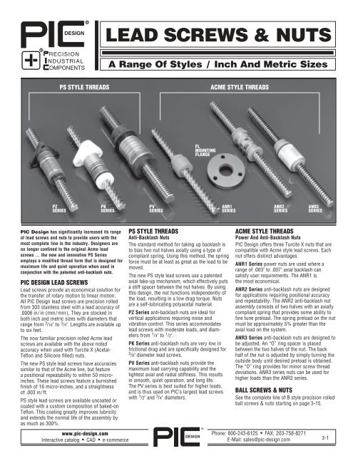
PS STYLE THREADS ACME STYLE THREADS<br />
PZ PK PV ANR1 ANR2 ANR3<br />
SERIES SERIES SERIES SERIES SERIES SERIES<br />
<strong>PIC</strong> <strong>Design</strong> has significantly increased its range<br />
of lead screws and nuts to provide users with the<br />
most complete line in the industry. <strong>Design</strong>ers are<br />
no longer confined to the original Acme lead<br />
screws ... the new and innovative PS Series<br />
employs a modified thread form that is designed for<br />
maximum life and quiet operation when used in<br />
conjunction with the patented anti-backlash nuts.<br />
<strong>PIC</strong> DESIGN <strong>LEAD</strong> <strong>SCREWS</strong><br />
Lead screws provide an economical solution for<br />
the transfer of rotary motion to linear motion.<br />
All <strong>PIC</strong> <strong>Design</strong> lead screws are precision rolled<br />
from 303 stainless steel with a lead accuracy of<br />
.0006 in/ in (mm/ mm). They are stocked in<br />
both inch and metric sizes with diameters that<br />
range from 3 /16" to 3 /4". Lengths are available up<br />
to six feet.<br />
The now familiar precision rolled Acme lead<br />
screws are available with the above noted<br />
accuracy when used with Turcite X (Acetal-<br />
Teflon and Silicone filled) nuts.<br />
The new PS style lead screws have accuracies<br />
similar to that of the Acme line, but feature<br />
a positional repeatability to within 50 microinches.<br />
These lead screws feature a burnished<br />
finish of 16 micro-inches, and a straightness<br />
of .003 in/ ft.<br />
PS style lead screws are available uncoated or<br />
coated with a custom composition of baked-on<br />
Teflon. This coating greatly improves lubricity<br />
and extends the normal life of the assembly by<br />
as much as 300%.<br />
DESIGN<br />
FL<br />
MOUNTING<br />
FLANGE<br />
PS STYLE THREADS<br />
Anti-Backlash Nuts<br />
The standard method for taking up backlash is<br />
to bias two nut halves axially using a type of<br />
compliant spring. Using this method, the spring<br />
force must be at least as great as the load to be<br />
moved.<br />
The new PS style lead screws use a patented<br />
axial take-up mechanism, which effectively puts<br />
a stiff spacer between the nut halves. By using<br />
this design, the nut functions independently of<br />
the load, resulting in a low drag torque. Nuts<br />
are a self-lubricating polyacetal material.<br />
PZ Series anti-backlash nuts are ideal for<br />
vertical applications requiring noise and<br />
vibration control. This series accommodates<br />
lead screws with moderate loads, and diameters<br />
from 1 /4" to 1 /2".<br />
PK Series anti-backlash nuts are very low in<br />
frictional drag and are specifically designed for<br />
3 /8" diameter lead screws.<br />
PV Series anti-backlash nuts provide the<br />
maximum load carrying capability and the<br />
lightest axial and radial stiffness. This results<br />
in smooth, quiet operation, and long life.<br />
The PV series is best suited for higher loads,<br />
and is thus used on <strong>PIC</strong>’s largest lead screws<br />
with 1 /2" and 3 /4" diameters.<br />
®<br />
ACME STYLE THREADS<br />
Power And Anti-Backlash Nuts<br />
<strong>PIC</strong> <strong>Design</strong> offers three Turcite X nuts that are<br />
compatible with Acme style lead screws. Each<br />
nut offers distinct advantages.<br />
ANR1 Series power nuts are used where a<br />
range of .003" to .007" axial backlash can<br />
satisfy user requirements. The ANR1 is<br />
the most economical.<br />
ANR2 Series anti-backlash nuts are designed<br />
for applications requiring positional accuracy<br />
and repeatability. The ANR2 anti-backlash nut<br />
assembly consists of two halves with an axially<br />
compliant spring that provides some ability to<br />
fine tune preload. The spring preload on the nut<br />
must be approximately 5% greater than the<br />
axial load on the system.<br />
ANR3 Series anti-backlash nuts are designed to<br />
be adjusted. An “O” ring spacer is placed<br />
between the two halves of the nut. The back<br />
half of the nut is adjusted by simply turning the<br />
outside body until desired preload is obtained.<br />
The “O” ring provides for minor screw thread<br />
deviations. ANR3 series nuts can be used for<br />
higher loads than the ANR2 series.<br />
BALL <strong>SCREWS</strong> & <strong>NUTS</strong><br />
See the complete line of B style precision rolled<br />
ball screws & nuts starting on page 3-15.<br />
Phone: 800-243-6125 ■ FAX: 203-758-8271<br />
E-Mail: sales@pic-design.com<br />
3-1
TECHNICAL SECTION<br />
Lead Screw Assembly<br />
TERMINOLOGY<br />
The glossary of terms and basic formulas presented below will aid designers<br />
in evaluating system requirements. Critical system parameters such as<br />
torque, efficiency, maximum load and critical speed are easily evaluated.<br />
— Lead Screw Assembly: A screw and nut device used for the purpose<br />
of transmitting motion or power as opposed to fastening.<br />
— Backlash: Free axial movement between screw and nut.<br />
— Column Strength: Maximum compressive load that can be applied to<br />
a shaft without taking a permanent set.<br />
— Critical Speed: Operating speed of spinning shaft that develops<br />
severe vibrations during rotation. This is a function of length,<br />
diameter and end supports.<br />
— Drag Torque: The torque necessary to drive the lead screw<br />
assembly alone.<br />
— Efficiency: Ratio of work output to work input; varies with lead,<br />
thread angle and coefficient of friction (see screw data).<br />
— Lead: Distance traveled by the nut in one revolution (equal to the<br />
screw pitch x the number of starts).<br />
— Lead Angle: The angle made by the helix of the thread at the<br />
screw pitch line with plane perpendicular to the screw axis.<br />
— Major Diameter: The diameter of a cylinder formed by the crests<br />
of the thread.<br />
— Minor Diameter: The root diameter.<br />
— Pitch: The distance as measured parallel to the thread axis between<br />
corresponding points on adjacent thread forms, generally equal to the<br />
lead divided by the number of starts.<br />
— Self Locking: When it is impossible for a thrust load on a nut to<br />
create a torque on its screw, the screw and nut are said to be selflocking.<br />
A self-locking screw will not convert thrust to torque.<br />
Generally, Acme screws are self-locking while most high lead and ball<br />
screw are non self-locking. A non self-locking screw will require a<br />
mechanical brake or some other locking means to a sustain a load.<br />
— Stroke: The axial distance traveled by the nut in either direction.<br />
— Thread per inch: The reciprocal of the pitch is the number of threads<br />
per inch.<br />
The application engineering information in this section should enable the<br />
designer to fully evaluate the lead screws offered in this catalog.<br />
CRITICAL SPEED / ANGULAR VELOCITY<br />
When a shaft is spinning, as in the case of an operating Lead screw, it will<br />
experience excessive vibration at a speed approximating its natural frequency<br />
of vibration. This speed is called the “Critical Speed” and good<br />
design practice dictates that speed should be limited to 85% of a shaft’s first<br />
order critical speed. Critical speed is a function of shaft diameter, end<br />
support configuration and unsupported length. These speeds are shown in<br />
graphic form for various shaft diameters, lengths and supports.<br />
COLUMN STRENGTH / COMPRESSION LOAD<br />
Under compressive loading a sufficiently slender shaft will fail by elastic<br />
instability at a load well below the shaft’s elastic limit or rated load. A graph<br />
is provided to show the maximum safe column load for various diameters,<br />
lengths and supports. Shaft slenderness ratios exceeding 200 are not<br />
recommended and the curves are dotted for these ratios. Column strength<br />
limitations do not apply to shafts under tension loads.<br />
3-2<br />
Phone: 800-243-6125 ■ FAX: 203-758-8271<br />
E-Mail: sales@pic-design.com<br />
TORQUE, ROTARY TO LINEAR (Torque needed to move load)<br />
DESIGN<br />
®<br />
Torque (in. lbs.) =<br />
Load (lbs.) x Lead (inches)<br />
2π x efficiency<br />
TORQUE, LINEAR TO ROTARY (Backdriving Torque)<br />
Load x Lead x Efficiency<br />
Torque to hold load =<br />
2π<br />
If greater than 1 may backdrive*<br />
FORWARD DRIVING EFFICIENCY (See screw data)<br />
E F = (tan λ) [(cos Φn - f tan λ) / (cos Φn tan λ + f )]<br />
BACKWARD DRIVING EFFICIENCY<br />
E B = (1/tan λ) [(cos Φn tan λ - f ) / (cos Φn + f tan λ) ]<br />
= Load x Lead x Efficiency<br />
2π<br />
f = Coefficient of friction<br />
E B = Back drive efficiency<br />
E F = Forward drive efficiency<br />
λ = Thread lead angle<br />
Φn = Thread angle in normal plane. (29° for ACME Thread,<br />
30° for Metric Trapezoidal, 40° for Precision PS Series.)<br />
SCREW RPM<br />
Velocity (in/min)<br />
RPM =<br />
Lead (in/ rev)<br />
COLUMN LOAD STRENGTH (Based on Eulers Formula)<br />
Pcr = 14.03 x 10⁶Fcd4 L2 Pcr = maximum load (lbs.)<br />
Fc = end support factor (see page 3-3)<br />
= .25 one end fixed, other free<br />
= 1.00 both ends supported<br />
= 2.00 one end fixed, other supported<br />
= 4.00 both ends fixed<br />
d = root diameter of screw (inches)<br />
L = maximum distance between nut & load carrying<br />
bearing (inches)<br />
When possible, design for tension loads to eliminate the buckling<br />
factor and reduce the required screw size.<br />
CRITICAL SCREW SHAFT SPEED<br />
(Maximum rotational speed of a screw)<br />
Cs = F x 4.76 x 10⁶ x d<br />
L2 Cs = Critical speed (RPM)<br />
d = root diameter of screw (inches)<br />
L = Length between supports (inches)<br />
F = end support factor (see page 3-3)<br />
.36 one end fixed, other free<br />
1.00 simple supports both ends<br />
1.47 one end fixed, one simple<br />
2.23 both ends fixed<br />
Critical shaft speed should be reduced to 85% to allow for other<br />
factors such as alignment and straightness.<br />
* If the lead is greater than 1/3 of the diameter, it may backdrive<br />
www.pic-design.com<br />
Interactive catalog ■ CAD ■ e-commerce
CRITICAL <strong>LEAD</strong> SCREW SPEED vs. <strong>LEAD</strong> SCREW LENGTH<br />
RPM's<br />
10,000<br />
9,000<br />
8,000<br />
7,000<br />
6,000<br />
5,000<br />
4,000<br />
3,000<br />
2,000<br />
1,500<br />
1,000<br />
900<br />
800<br />
700<br />
600<br />
500<br />
400<br />
300<br />
200<br />
100<br />
Curves for the Acme screws shown<br />
are based on the minor root<br />
diameter of standard screws and<br />
tolerances within the size range.<br />
1/4<br />
5/16<br />
3/8 7/16<br />
A Fixed-Free 612 18 24 30 3642 48 54 60<br />
B Simple-Simple 10 20 30 40 50 60 70 80 90 100<br />
C Fixed-Simple 12 24 3648 61 73 85 97 109 121<br />
D Fixed-Fixed 15 30 45 60 75 90 105 119 134 149<br />
Maximum Length Between Bearings (Inches)<br />
ASCERTAINING CRITICAL SHAFT SPEED<br />
1. Examine the drawings to the right and determine the type of lead<br />
screw end support bearing employed — A, B, C or D.<br />
2. Determine the maximum length between end supports. Locate that<br />
number, in the table above, opposite the appropriate end support.<br />
3. Locate the vertical line on the graph that matches the number in<br />
step 2. Where this line intersects the appropriate diameter lead<br />
screw curve, determine critical shaft speed. <strong>PIC</strong> <strong>Design</strong> recommends<br />
operating at a speed less than 85% of this number in order to allow<br />
for any misalignments.<br />
www.pic-design.com<br />
Interactive catalog ■ CAD ■ e-commerce<br />
1 /2<br />
3/4<br />
5/8<br />
COMPRESSION LOAD (Lbs)<br />
DESIGN<br />
TECHNICAL SECTION<br />
10,000<br />
9,000<br />
8,000<br />
7,000<br />
6,000<br />
5,000<br />
4,000<br />
3,000<br />
2,000<br />
1,500<br />
1,000<br />
900<br />
800<br />
700<br />
600<br />
500<br />
400<br />
300<br />
200<br />
100<br />
®<br />
Critical Speed and Compression Load Determination<br />
MAXIMUM COMPRESSION LOAD vs. <strong>LEAD</strong> SCREW LENGTH<br />
1 /4 5 /16 3/8<br />
Curves for the Acme screws shown<br />
are based on the minor root<br />
diameter of standard screws and<br />
tolerances within the size range.<br />
7/16 1/2<br />
A Fixed-Free 5 10 15 20 25 30 35 40 45<br />
B Simple-Simple 10 20 30 40 50 60 70 80 90<br />
C Fixed-Simple 14 28 42 57 71 85 99 113 127<br />
D Fixed-Fixed 20 40 60 80 100 120 140 160 180<br />
Maximum Length Between Bearings (Inches)<br />
ASCERTAINING COMPRESSION LOADS<br />
Use procedure similar to that for finding critical shaft speed<br />
END SUPPORT CONFIGURATIONS<br />
A Fixed-Free<br />
C Fixed-Simple<br />
5/8<br />
B Simple-Simple<br />
D Fixed-Fixed<br />
Phone: 800-243-6125 ■ FAX: 203-758-8271<br />
E-Mail: sales@pic-design.com<br />
3/4<br />
3-3
TECHNICAL SECTION<br />
Axial Take-Up Mechanisms<br />
TY<strong>PIC</strong>AL SOLUTIONS —<br />
Backlash Compensation Without High Drag Torque<br />
The standard method for taking<br />
up backlash is to bias two nut<br />
halves axially using some type<br />
of compliant spring. (Wavy<br />
washer, compression spring,<br />
rubber washer, etc.)<br />
The unit is very stiff in the direction in which the nut half is loaded<br />
against the flank of the screw thread. However, in the direction away<br />
from the screw thread, the nut<br />
is only as axially stiff as the<br />
amount of preload which the<br />
spring exerts.<br />
For example, if the maximum<br />
axial load which the system is<br />
subjected to is 50 lbs., the amount of spring preload must be equal to<br />
or greater than 50 lbs. in order to maintain intimate screw/nut contact.<br />
The problems arising from preloading in this manner are increased<br />
torque and nut wear.<br />
An alternate method would thus be to replace the spring with a stiff<br />
spacer sized to fit exactly between the two nut halves.<br />
There would then be no<br />
excessive preload force at the<br />
interface and the unit would<br />
be capable of carrying high<br />
axial loads in either direction<br />
with no backlash.<br />
End Machining<br />
Available at an additional cost. <strong>PIC</strong> offers a typical journal for use with a<br />
bearing/ mount support. Custom end machining available. Send drawing<br />
with your RFQ.<br />
— Please Note:<br />
— Bearing Shaft Spacers are listed in Catalog Section 6<br />
— Couplings are listed in Catalog Section 7<br />
— Linear Bearings and Shafting are listed in Catalog Section 4<br />
3-4<br />
Phone: 800-243-6125 ■ FAX: 203-758-8271<br />
E-Mail: sales@pic-design.com<br />
This is fine initially. However, as<br />
use time increases, wear begins<br />
on the nut threads causing a gap<br />
to develop between the spacer<br />
(L) and the nut halves.<br />
This gap (Δ1 +Δ 2) is now the<br />
amount of backlash which has developed in the unit. This backlash can be<br />
removed by replacing the stiff spacer with a new spacer equal to<br />
(L + Δ1 +Δ 2). This process, although effective, would be extremely<br />
costly and difficult to implement on a continuous basis.<br />
A PATENTED SOLUTION<br />
What is needed, then, is a stiff spacer which will continually expand to<br />
accommodate the wear which occurs during use.<br />
This is done by creating a spacer threaded at one end with a complimentary<br />
nut torsionally biased to advance when a gap develops.<br />
The thread at the end of the spacer is a fine helix such that an axial load<br />
will not backdrive the nut once<br />
spacer growth has occurred.<br />
The amount of preload on the<br />
unit is only that necessary to<br />
turn the spacer nut on the<br />
spacer rod and is independent<br />
of the external system<br />
loadings. THIS PATENTED<br />
DESIGN HAS A SELF-WEAR COMPENSATING UNIT WHICH HAS EX-<br />
TREMELY LOW FRICTIONAL DRAG TORQUE YET HIGH AXIAL STIFF-<br />
NESS.<br />
JOURNAL/END MACHINING & MOUNTING ACCESORIES<br />
For Use With Series S10 and S12 Blocks<br />
UNDERCUT - .04 Max Width<br />
.015 Max Depth<br />
D +.0000<br />
-.0003 D +.000<br />
-.001<br />
L<br />
D<br />
The data presented below will be useful when designing lead screw systems<br />
using Series S10 Universal Bearing Blocks and Series S12 Bearing Blocks.<br />
When Using Series S10 Universal Bearing Blocks<br />
Screw<br />
Dia.<br />
When Using Series S12 Bearing Blocks<br />
Screw<br />
Dia.<br />
D<br />
Journal<br />
Dia.<br />
L<br />
Journal<br />
Length<br />
Flange<br />
Adaptor<br />
Flange<br />
Spacer<br />
Flanged<br />
Ball<br />
Bearing<br />
Bearing<br />
Housing<br />
3 /16 0.1247 0.6 LMB-4 E2-3 S12-4<br />
1 /4 0.1247 0.6 LMB-4 E2-3 S12-4<br />
5 /16 0.1872 0.75 LMB-6 E2-6 S12-5<br />
3/8 0.2497 0.813 LMB-6 E2-9 S12-8<br />
7/16 0.2497 0.813 LMB-8 E2-9 S12-8<br />
1/2 0.2497 0.813 LMB-8 SMB-8 E2-9 S12-8<br />
5 /8 0.3747 1.083 LMB-10 SMB-10 E2-15 S12-10<br />
DESIGN<br />
®<br />
D L<br />
Journal Journal<br />
Dia. Length<br />
Ball Retaining Shim Shaft<br />
Bearing Ring Pack Collar<br />
3/16 0.1247 1.00 E1-3 Z1-1 SP-06 C1-1<br />
1 /4 0.1247 1.00 E1-3 Z1-1 SP-06 C1-1<br />
5 /16 0.1872 1.12 E1-8 Z1-2 SP-08 C1-2<br />
3 /8 0.2497 1.12 E1-9 Z1-3 SP-10 C1-3<br />
7 /16 0.2497 1.12 E1-9 Z1-3 SP-10 C1-3<br />
1/2 0.3747 1.38 E1-15 Z1-5 SP-14 C1-10<br />
5/8 0.3747 1.38 E1-15 Z1-5 SP-14 C1-10<br />
www.pic-design.com<br />
Interactive catalog ■ CAD ■ e-commerce
www.pic-design.com<br />
Interactive catalog ■ CAD ■ e-commerce<br />
PRECISION PS STYLE <strong>LEAD</strong> <strong>SCREWS</strong><br />
For use with PZ, PK and PV Style Nuts .0006 Inch/ Inch (mm/ mm) Lead Accuracy<br />
Part Number<br />
PS<br />
■<br />
Part Number<br />
from Table<br />
Screw Dia.<br />
1 /4<br />
3 /8<br />
7 /16<br />
1 /2<br />
3 /4<br />
—<br />
■<br />
Coating:<br />
T = Teflon<br />
Blank = no coating<br />
■<br />
Length in inches<br />
(Consult factory for special lengths)<br />
Material: 303 Stainless Steel<br />
Repeatability: .000050 inches<br />
System (lead screw and nut) Specification<br />
Operating Temperature Range: 32OF - 200OF (0OC-93OC) Coefficient Of Friction (Nut To Screw): .08 Static<br />
.15 Dynamic<br />
(.09 when TFE coated)<br />
Features:<br />
● Precision rolled<br />
● Lead screw accuracy of<br />
.0006 in./ in. (mm/ mm)<br />
● Straightness tolerance of<br />
.003 in/ ft.<br />
● Screws have burnished finish<br />
of better than 16 micro-inch<br />
due to the rolling process<br />
Lead<br />
(in. or mm)<br />
Root Dia.<br />
in. (mm)<br />
Efficiency EF<br />
( % )<br />
Standard<br />
Length (in.)<br />
** Part No.<br />
0.062 0.170 52 PS4006 -<br />
0.250<br />
1.000<br />
0.168<br />
0.170<br />
79<br />
84<br />
12, 36, 72<br />
PS4025<br />
PS4100<br />
-<br />
-<br />
1.5 mm 0.172 (4.37) 51 PS4M01.5 -<br />
DESIGN<br />
®<br />
● 303 Stainless steel used for<br />
uniform grain structure to<br />
improve lead accuracy<br />
● Available with custom TFE<br />
coating to extend normal life in<br />
as much as 300%<br />
0.100 0.266 53 PS6010 - *<br />
0.200 0.266 69 PS6020 -<br />
0.300 0.255 76 PS6030 -<br />
0.500<br />
1.000<br />
0.265<br />
0.254<br />
81<br />
84<br />
12, 36, 72<br />
PS6050<br />
PS6100<br />
-<br />
-<br />
*<br />
1.200 0.254 84 PS6120 -<br />
2 mm 0.254 (6.45) 47 PS6M02 -<br />
5 mm 0.266 (6.76) 69 PS6M05 -<br />
0.250 0.325 70 PS7025 -<br />
0.500<br />
3 mm<br />
0.328<br />
0.363 (9.22)<br />
80<br />
52<br />
24, 48, 72<br />
PS7050<br />
PS7M03<br />
-<br />
-<br />
5 mm 0.313 (7.95) 65 PS7M05 -<br />
0.050 0.433 28 PS8005 -<br />
0.100 0.364 46 PS8010 - *<br />
0.200<br />
0.500<br />
0.366<br />
0.352<br />
63<br />
79<br />
24, 48, 72<br />
PS8020<br />
PS8050<br />
-<br />
-<br />
*<br />
1.000 0.372 84 PS8100 - *<br />
1.000 0.619 81<br />
PS12100 - *<br />
24, 48, 72<br />
2.000 0.611 84 PS12200 -<br />
NOTES: When Teflon coating is used, do not use lubrication. Random voids in the teflon coating have no effect<br />
on system performance. The lubricant, although solid, has some “spreading” ability as in fluid lubricants<br />
Uncoated screws should not require lubrication. For those instances where lubrication may be desired, a<br />
silicone or lithium-based lubricant is suggested.<br />
** Left hand thread available.<br />
** For Teflon coating insert a<br />
T before dash.<br />
For Example: PS4006T - 72<br />
Phone: 800-243-6125 ■ FAX: 203-758-8271<br />
E-Mail: sales@pic-design.com<br />
3-5
PZ STYLE <strong>LEAD</strong> SCREW <strong>NUTS</strong><br />
For Use With PS Series Lead Screws<br />
PZ style nuts provide anti-backlash for light loads operating at<br />
moderate speeds. These nuts utilize a patented self-lubricating<br />
polyacetal radially pre-loaded nut. They are ideally suited for vertical<br />
applications requiring noise and vibration control. PZ style nuts are<br />
used in conjunction with<br />
1 /4" to 1 /2" diameter lead screws.<br />
This anti-backlash assembly offers an effective linear actuator for<br />
design operations requiring precise positional accuracy and repeatability,<br />
with minimum cost.<br />
PZ Standard Mounting Dimensions<br />
3-6<br />
Phone: 800-243-6125 ■ FAX: 203-758-8271<br />
E-Mail: sales@pic-design.com<br />
NUT SPECIFICATIONS<br />
Material: Polyacetal with lubricating additive<br />
Tensile Strength: 9,700 PSI at 73 O F<br />
Shear Strength: 9,500 PSI at 73 O F<br />
SYSTEM (NUT AND <strong>LEAD</strong> SCREW) SPECIFICATIONS<br />
Temperature Range: 32 O F to 200 O F<br />
Coefficient of Friction: .08 Static to .15 Dynamic<br />
Coefficient of Thermal Expansion: 6 x 10 -5 in./ in./ O F<br />
Screw Dia.<br />
1 /4<br />
3/8<br />
7 /16<br />
1/2<br />
INTEGRALLY MOLDED FLANGE MOUNT<br />
DESIGN<br />
®<br />
Lead<br />
(in. or mm)<br />
Drag<br />
Torque<br />
<strong>Design</strong><br />
Load<br />
Part No.<br />
0.062 PZ4006N<br />
0.250 1-4 oz.- in. 5 lbs. PZ4025N<br />
1.000 PZ4100N<br />
1.5 mm (.007 - .03NM) (2kg) PZ4M01.5N<br />
0.100 PZ6010N<br />
0.200 PZ6020N<br />
0.300<br />
0.500<br />
2-5 oz.- in. 10 lbs.<br />
PZ6030N<br />
PZ6050N<br />
1.000 PZ6100N<br />
1.200 PZ6120N<br />
2mm<br />
5mm<br />
(.014 - .035NM) (5kg)<br />
PZ6M02N<br />
PZ6M05N<br />
0.250<br />
0.500<br />
3-6 oz.- in. 15 lbs.<br />
PZ7025N<br />
PZ7050N<br />
3mm<br />
5mm<br />
(.021 - .04NM) (7kg)<br />
PZ7M03N<br />
PZ7M05N<br />
0.050 PZ8005N<br />
0.100 PZ8010N<br />
0.200 3-6 oz.- in. 25 lbs. PZ8020N<br />
0.500 (.021 - .04NM) (.021 - .04NM) PZ8050N<br />
1.000 PZ8100N<br />
Screw Nut Nut Flange Flange Mounting Bolt Circle<br />
Series Dia. A Dia. B Length C Dia. D Width E Holes F Dia. G<br />
in. (mm) in. (mm) in. (mm) in. (mm) in. (mm) in. (mm) in. (mm)<br />
PZ4000 1 /4 (6.35) .50 (12.70) 1.0 (25.40) 1.00 (25.40) .18 (4.57) .143 (3.63) .750 (19.05)<br />
PZ6000 3/8 (9.53) .70 (17.78) 1.9 (48.28) 1.50 (38.10) .18 (4.57) .200 (5.08) 1.125 (28.58)<br />
PZ7000 7 /16 (11.11) .800 (20.32) 1.9 (48.26) 1.50 (38.10) .18 (4.57) .200 (5.08) 1.125 (28.58)<br />
PZ8000 1 /2 (12.70) .890 (22.61) 2.0 (50.80) 1.62 (41.15) .26 (6.60) .200 (5.08) 1.250 (31.75)<br />
Other Mountings Available — Please Contact <strong>PIC</strong> For Information<br />
www.pic-design.com<br />
Interactive catalog ■ CAD ■ e-commerce
PK style anti-backlash nuts feature a patented split nut with torsional<br />
take up to provide increased load capacity and axial stiffness. This<br />
design while high in axial stiffness is very low in frictional drag torque<br />
(1-3 oz-in). The type of anti-backlash mechanism used in the PK type<br />
nut eliminates the need for load compensating preload forces. This<br />
series is specifically made for screws of 3 /8" diameter, moderate loads<br />
and speeds.<br />
PK Standard Mounting Dimensions<br />
www.pic-design.com<br />
Interactive catalog ■ CAD ■ e-commerce<br />
PK STYLE <strong>LEAD</strong> SCREW <strong>NUTS</strong><br />
DESIGN<br />
®<br />
For Use With PS Series Lead Screws<br />
NUT SPECIFICATIONS<br />
Material: Polyacetal with lubricating additive<br />
Tensile Strength: 9,700 PSI at 73 O F<br />
Shear Strength: 9,500 PSI at 73 O F<br />
SYSTEM (NUT AND <strong>LEAD</strong> SCREW) SPECIFICATIONS<br />
Temperature Range: 32 O F to 200 O F<br />
Coefficient of Friction: .08 Static to .15 Dynamic<br />
Coefficient of Thermal Expansion: 6x10 -5 in./ in./ O F<br />
Screw Dia.<br />
3 /8<br />
Lead<br />
(in. or mm)<br />
Drag<br />
Torque<br />
<strong>Design</strong><br />
Load<br />
Part No.<br />
0.100 PK6010N<br />
0.200 PK6020N<br />
0.300<br />
0.500<br />
1-3 oz.- in. 20 lbs.<br />
PK6030N<br />
PK6050N<br />
1.000 PK6100N<br />
1.200 PK6120N<br />
2mm<br />
5mm<br />
(.007 - .02NM) (10kg)<br />
PK6M02N<br />
PK6M05N<br />
INTEGRALLY MOLDED FLANGE MOUNT<br />
Series<br />
Screw<br />
Dia. A<br />
Nut<br />
Dia. B<br />
Nut<br />
Length C<br />
Flange<br />
Dia. D<br />
Flange<br />
Width E<br />
Mounting<br />
Holes F<br />
Bolt Circle<br />
Dia. G<br />
PK6000 (in.) 3 /8 .80 2.0 1.5 .19 .20 1.125<br />
PK6000 (mm.) 9.53 20.32 50.80 38.10 4.83 5.08 28.58<br />
Phone: 800-243-6125 ■ FAX: 203-758-8271<br />
E-Mail: sales@pic-design.com<br />
3-7
PV STYLE <strong>LEAD</strong> SCREW <strong>NUTS</strong><br />
For Use With PS Series Lead Screws<br />
PV style anti-backlash nuts provide a maximum load carrying<br />
capability and the lightest axial and radial stiffness of all <strong>PIC</strong> antibacklash<br />
nuts. They are designed for smooth, quiet operation and long<br />
life, made possible by a patented axial take-up mechanism. Because<br />
this series is designed to operate with higher loads, operation is only<br />
possible with 1 /2" and 3 /4" diameter lead screws.<br />
PV Standard Mounting Dimensions<br />
3-8<br />
Phone: 800-243-6125 ■ FAX: 203-758-8271<br />
E-Mail: sales@pic-design.com<br />
NUT SPECIFICATIONS<br />
Material: Polyacetal with lubricating additive<br />
Tensile Strength: 9,700 PSI at 73 O F<br />
Shear Strength: 9,500 PSI at 73 O F<br />
SYSTEM (NUT AND <strong>LEAD</strong> SCREW) SPECIFICATIONS<br />
Temperature Range: 32 O F to 200 O F<br />
Coefficient of Friction: .08 Static to .15 Dynamic<br />
Coefficient of Thermal Expansion: 6x10 -5 in./ in./ O F<br />
Screw Dia.<br />
1 /2<br />
3 /4<br />
DESIGN<br />
®<br />
Lead<br />
(in. or mm)<br />
Drag<br />
Torque<br />
<strong>Design</strong><br />
Load<br />
Part No.<br />
0.050 PV8005N<br />
0.100 PV8010N<br />
0.200 2-6 oz.- in. 150 lbs. PV8020N<br />
0.500 (.01 - .04NM) (68kg) PV8050N<br />
1.000 PV8100N<br />
1.000 3-7 oz.- in. 350 lbs. PV12100N<br />
2.000 (.02 - .05NM) (159kg) PV12200N<br />
Screw Nut Nut Flange Flange Pilot Pilot Bolt Circle<br />
Series Dia. A Dia. B Length CF Dia. D Width E Dia. F Depth G Dia. H<br />
in. (mm) in. (mm) in. (mm) in. (mm) in. (mm) in. (mm) in. (mm) in. (mm)<br />
PV8000 1/2 (12.70) 1.12 (28.45) 2.3 (58.42) 1.75 (44.45) .23 (5.84) .93 (23.63) .12 (3.05) 1.406 (35.71)<br />
PV12000 3 /4 (19.05) 1.62 (41.15) 2.8 (71.12) 2.38 (60.45) .31 (7.87) — — — — 2.00 (50.80)<br />
Please Contact <strong>PIC</strong> For Optional Mounting Threads Or Special Configuration Requirements.<br />
120 o<br />
Typ<br />
INTEGRALLY MOLDED FLANGE MOUNT<br />
www.pic-design.com<br />
Interactive catalog ■ CAD ■ e-commerce
Inch and Metric<br />
Part Number<br />
ARS<br />
X<br />
■<br />
From Table<br />
www.pic-design.com<br />
Interactive catalog ■ CAD ■ e-commerce<br />
PRECISION ACME <strong>LEAD</strong> <strong>SCREWS</strong><br />
—<br />
■<br />
Specify Length<br />
code (inches) on<br />
metric threads<br />
(meters)<br />
Material: 303 Stainless Steel<br />
Features:<br />
● Screws are precision rolled.<br />
● Lead accuracy of ±.003"<br />
per foot.<br />
● Straightness tolerance of<br />
.010" per foot.<br />
Teflon “S” Coating Properties:<br />
● Coefficient of friction:<br />
static = .12<br />
dynamic = .10<br />
● Hardness, coating Knoop<br />
scale 9- 12<br />
DESIGN<br />
®<br />
.003 Inch/ Foot Lead Accuracy<br />
● Class 2G Thread<br />
● Burnished finish of 24 RMS or<br />
better due to the rolling process.<br />
● 303 stainless steel used for<br />
uniform grain structure to improve<br />
lead accuracy and finish.<br />
Available on request & special quotation:<br />
● Teflon “S” coated lead screw assemblies with film thickness of .0005 to<br />
.001. Coating improves distribution of lubricant whereby it improves the<br />
coefficient of friction between the nut and screw, with reduced torque<br />
needed to drive the lead screw assembly. The Teflon coated lead screw<br />
assembly increases useful life of the system by more than twofold.<br />
● Abrasion resistance (TABER)<br />
(weight loss in grams,<br />
100 cycles) .04<br />
● Thickness .0005 to.001 in.<br />
Screw Dia. Screw Lead Minor Root Dia. Efficiency Weight per ft. Standard Length Part No.<br />
(in.) Size (in.) (in.) ( % ) (lbs.) ( in.) Add length to end of Part No.<br />
3/16 3/16 - 20 0.050 0.119 46 .06 ARS1X1820 -<br />
1<br />
/4<br />
1/4 - 20<br />
1 /4 - 16<br />
0.050<br />
0.0625<br />
0.190<br />
0.170<br />
38<br />
44<br />
.13<br />
.13<br />
ARS1X2520 -<br />
ARS1X2516 -<br />
*<br />
*<br />
5/16 5/16 - 8, 4 start (stub) 0.500 0.218 71 .19 ARS4X3108 -<br />
3 /8 - 20 0.050 0.315 29 .31 ARS1X3720 -<br />
3 /8 - 16 0.0625 0.303 34 .31 ARS1X3716 - *<br />
3 /8 - 10 0.100 0.255 46 .27 12, 36, 72 ARS1X3710 - *<br />
3 /8 - 8 (stub) 0.125 0.280 52 .30 ARS1X3708 -<br />
3 /8 3 /8 - 10, 2 start 0.200 0.255 66 .27 ARS2X3710 -<br />
3 /8 - 8, 2 start (stub) 0.250 0.280 67 .26 ARS2X3708 -<br />
3 /8 - 8, 4 start (stub) 0.500 0.270 77 .28 ARS4X3708 -<br />
3/8 - 5, 5 start<br />
3 /8 - 4, 5 start (stub)<br />
1.000<br />
1.250<br />
0.255<br />
0.243<br />
79<br />
75<br />
.27<br />
.28 12, 36<br />
ARS5X3705 -<br />
ARS5X3704 -<br />
**<br />
**<br />
7 /16<br />
1 /2<br />
7 /16 - 8, 2 start (stub) 0.250 0.327 64 .40 ARS2X4308 -<br />
7 /16 - 8, 4 start (stub) 0.500 0.327 75 .42 ARS4X4308 -<br />
1/2 - 10 0.100 0.380 38 .53 ARS1X5010 - *<br />
1 /2 - 10, 2 start 0.200 0.380 55 .80 24, 48, 72 ARS2X5010 -<br />
5 /8 - 10 0.100 0.505 32 .85 ARS1X6210 - *<br />
5 /8 5 /8 - 8 (stub) 0.125 0.530 38 .48 ARS1X6208 -<br />
5 /8 - 10, 2 start 0.200 0.505 49 .85 ARS2X6210 -<br />
Screw Dia. Trapezoidal Metric Thread Lead Minor Root Dia. Efficiency Weight per meter Standard Length Part No.<br />
(mm) (ISO) (mm) (mm) ( % ) (kg) (meter) Add length to end of Part No.<br />
4 4 x 1 mm 1 2.5 44 .3 ARS1X041M -<br />
8 8 x 2 mm 2 5.5 44 .6 ARS1X082M -<br />
10 10 x 2 mm 2 7.5 38 .7 .5, 1.0, 1.8 ARS1X102M -<br />
10 10 x 1.5 mm, 4 start 6 7.9 63 .7 ARS4X101M - ***<br />
14 14 x 4 mm 4 9.5 47 .9 ARS1X144M - ***<br />
NOTE: Screws should not require lubrication. For those instances where<br />
lubrication may be desired, a silicone or lithium-based lubricant is<br />
*** Left hand thread available.<br />
suggested.<br />
*** 36" max length.<br />
*** 416 Stainless Steel only.<br />
Phone: 800-243-6125 ■ FAX: 203-758-8271<br />
E-Mail: sales@pic-design.com<br />
3-9
ACME <strong>LEAD</strong> SCREW POWER <strong>NUTS</strong><br />
Inch and Metric For use with ACME Lead Screws<br />
Features:<br />
● Tensile strength (at break) 5900 PSI<br />
● Elongation (at break) 19%<br />
● Flexural yield strength 8000 PSI<br />
● Compressive strength 9500 PSI<br />
● Coefficient of friction:<br />
— static (40 psi) = .08<br />
— dynamic (40 psi / 50 fmp) = .12<br />
● Coefficient of linear thermal expansion 5.2 x 10 -5 in./ in./ O F<br />
● Limiting PV (1" dia shaft, 100 FPM) 16000 PSI-FPM<br />
For Mounting Flange, See Page 3-13<br />
Powernut Dimensions (in.)<br />
Major Dia. Lead Flange Max. Static<br />
(in.) (in.) D L A B No. Load<br />
3-10<br />
Phone: 800-243-6125 ■ FAX: 203-758-8271<br />
E-Mail: sales@pic-design.com<br />
Specifications:<br />
Hardness: Durometer Shore D 75<br />
Temperature Range: Min. 32OF, Max. 180OF Max. Speed (Unlubricated): 200 SF/M (surface feet per minute)<br />
Material: Turcite X (Acetal - Teflon and Silicon filled)<br />
Note:<br />
It is recommended that dynamic loads not exceed 25% of the static load<br />
rating. Factors such as speed, duty cycle, eccentric cantilever loading and<br />
temperature can adversely effect load ratings.<br />
1) Torque values to raise 1 lb. also apply to anti-backlash nuts for load torque calculations.<br />
2) Torque values are for nut & screw only, drag, bearing mounting & drive component<br />
inefficiencies need to be considered when determining total necessary torque<br />
DESIGN<br />
®<br />
Torque To Raise 1 lb.<br />
Load<br />
(Oz. - In.)<br />
Part No.<br />
3 /16 0.050 0.62 0.62 3 /16 9 /16 - 18 FL-3 150 lbs. 0.40 ANR11-1820<br />
1 /4<br />
0.050<br />
3 9<br />
0.62 0.62 /16 /16 - 18 FL-3 200 lbs.<br />
0.40 ANR11-2520<br />
0.0625 0.42 ANR11-2516<br />
5/16 0.500 0.75 0.75 1/4 5/8 - 18 FL-1 250 lbs. 1.8 ANR14-3108<br />
0.050 0.60 ANR11-3720<br />
0.0625 0.58 ANR11-3716<br />
0.100 0.64 ANR11-3710<br />
0.125 0.70 ANR11-3708<br />
3 /8 0.200 0.75 0.75 1 /4 5 /8 - 18 FL-1 350 lbs. 0.92 ANR12-3710<br />
0.250 1.1 ANR12-3708<br />
0.500 1.8 ANR14-3708<br />
1.000 3.5 ANR15-3705<br />
1.250 4.2 ANR15-3704<br />
7 /16<br />
0.250<br />
5 15<br />
1.00 1.00 /16 /16 - 16 FL-2 800 lbs.<br />
1.1 ANR12-4308<br />
0.500 1.9 ANR14-4308<br />
1<br />
/2<br />
0.100<br />
0.200<br />
1.00 1.00 5<br />
/16<br />
15<br />
/16 - 16 FL-2 800 lbs.<br />
0.80<br />
1.1<br />
ANR11-5010<br />
ANR12-5010<br />
0.100 0.80 ANR11-6210<br />
5/8 0.125 1.00 1.00 5/16 15/16 - 16 FL-2 800 lbs. 1.0 ANR11-6208<br />
0.200 1.1 ANR12-6210<br />
Powernut Dimensions (mm)<br />
Major Dia. Lead Flange Max. Static Torque To Raise 1 kg.<br />
(mm.) (mm.) D L A B No. Load<br />
Load<br />
(NM)<br />
Part No.<br />
4.0 1.0 15 20 5.0 M12 x 1.5 FLM-1 60 kg .004 ANR11-041m<br />
8.0 2.0 15 20 5.0 M12 x 1.5 FLM-1 100 kg .009 ANR11-082m<br />
10.0 2.0 25 25 6.4 M20 x 1.5 FLM-2 160 kg .013 ANR11-102m<br />
10.0 6.0 25 25 6.4 M20 x 1.5 FLM-2 160 kg .012 ANR14-101m<br />
14.0 4.0 25 25 6.4 M20 x 1.5 FLM-2 350 kg .015 ANR11-144m<br />
www.pic-design.com<br />
Interactive catalog ■ CAD ■ e-commerce
ACME <strong>LEAD</strong> SCREW ANTI-BACKLASH STYLE <strong>NUTS</strong><br />
For use with ACME Lead Screws Inch and Metric<br />
Preload may be increased slightly by adding a SHIM behind the<br />
spring, or decreased by respositioning one-half of the nut<br />
assembly away from the opposite half. Lubrication is recommended<br />
for continuous duty and high speed applications. It is<br />
recommended that drive motors be selected with at least 50%<br />
additional torque to handle other system inefficiencies.<br />
For Mounting Flange, See Page 3-13<br />
Major Dia. Lead<br />
(in.) (in.)<br />
www.pic-design.com<br />
Interactive catalog ■ CAD ■ e-commerce<br />
D<br />
Specifications:<br />
Temperature Range: Min. 32 O F, Max. 180 O F<br />
Material: Nut-Turcite X (Acetal - Teflon and Silicone filled)<br />
Material: Spring-300 Series Stainless Steel<br />
AB Nut Dimensions (in.) Max. Max Load For<br />
L<br />
Max. Min.<br />
A B<br />
Flange<br />
No.<br />
Preload<br />
(lbs.)<br />
Zero Backlash<br />
(lbs.)<br />
Torque*<br />
(Oz. - in.)<br />
DESIGN<br />
®<br />
Phone: 800-243-6125 ■ FAX: 203-758-8271<br />
E-Mail: sales@pic-design.com<br />
Part No.<br />
3/16 0.050 0.62 1.34 1.12 3/16 9/16 - 18 FL-3 5.25 5 6.7 ANR21-1820<br />
1 /4<br />
0.050<br />
3 9 6.7 ANR21-2520<br />
0.62 1.34 1.12 /16 /16 - 18 FL-3 5.25 5<br />
0.0625 6.1 ANR21-2516<br />
5 /16 0.500 0.75 1.7 1.4 1 /4 5 /8 - 18 FL-1 5.25 5 10.9 ANR24-3108<br />
0.050 11.0 ANR21-3720<br />
0.0625 8.5 ANR21-3716<br />
0.100 7.0 ANR21-3710<br />
0.125 7.0 ANR21-3708<br />
3 /8 0.200 0.75 1.7 1.4 1 /4 5 /8 - 18 FL-1 5.25 5 7.3 ANR22-3710<br />
0.250 8.0 ANR22-3708<br />
0.500 11.2 ANR24-3708<br />
1.000 19.4 ANR25-3705<br />
1.250 23.1 ANR25-3704<br />
7 /16<br />
0.250<br />
5 15 1.00 2.00 1.7 /16 /16 - 16 FL-2 11.55 11<br />
18.6 ANR22-4308<br />
0.500 25.3 ANR24-4308<br />
1<br />
/2<br />
0.100<br />
0.200<br />
1.00 2.00 1.7<br />
5<br />
/16<br />
15<br />
/16 - 16 FL-2 11.55 11<br />
19.3<br />
19.1<br />
ANR21-5010<br />
ANR22-5010<br />
0.100 22.8 ANR21-6210<br />
5 /8 0.125 1.00 2.00 1.7 5 /16 5 /16 - 16 FL-2 11.55 11 21.9 ANR21-6208<br />
0.200 21.8 ANR22-6210<br />
Major Dia. Lead<br />
(mm) (mm)<br />
D<br />
AB Nut Dimensions (mm) Max. Max Load For<br />
L<br />
Max. Min.<br />
A B<br />
Flange<br />
No.<br />
Preload<br />
(Kg)<br />
Zero Backlash<br />
(Kg)<br />
Torque*<br />
(NM)<br />
Part No.<br />
4.0 1.0 15 30 25 5.0 M12 x 1.5 FLM-1 2.4 2.3 .093 ANR21-041m<br />
8.0 2.0 15 30 25 5.0 M12 x 1.5 FLM-1 2.4 2.3 .124 ANR21-082m<br />
10.0 2.0 25 50 43 6.4 M20 x 1.5 FLM-2 5.2 5.0 .280 ANR21-102m<br />
10.0 6.0 25 50 43 6.4 M20 x 1.5 FLM-2 5.2 5.0 .275 ANR24-101m<br />
14.0 4.0 25 50 43 6.4 M20 x 1.5 FLM-2 5.2 5.0 .295 ANR21-144m<br />
*Torque figures are based on three factors: load, preload, and efficiency.<br />
3-11
ANR STYLE ADJUSTABLE COMPLIANT <strong>NUTS</strong><br />
Inch and Metric For Use With ACME Lead Screws<br />
Easily adjusted by turning adjusting nut for desired preload. Material:<br />
Nut: Turcite X<br />
Sleeve: Anodized Aluminum<br />
“ O ” Ring: Buna N<br />
For Mounting Flange, See Page 3-13<br />
Screw Dia. Lead<br />
(in.) (in.)<br />
3-12<br />
D<br />
Phone: 800-243-6125 ■ FAX: 203-758-8271<br />
E-Mail: sales@pic-design.com<br />
Specifications:<br />
Temperature Range: Min. 32 O F, Max. 180 O F<br />
Max. Speed (Unlubricated): 200 ft/ min<br />
Material: Turcite X (Acetal - Teflon and Silicon filled)<br />
Adjustable Nut Dimensions (in.) Max. Torque To<br />
L<br />
Max. Min.<br />
A B<br />
Flange<br />
No.<br />
Dynamic Load<br />
(lbs.)<br />
Raise 1 lb. Load<br />
(oz.- in.)<br />
DESIGN<br />
®<br />
Part No.<br />
3 /16 0.050 0.62 1.34 1.12 3 /16 9 /16 - 18 FL-3 35 .40 ANR31-1820<br />
1 /4<br />
0.050<br />
3 9 0.62 1.34 1.17 /16 /16 - 18 FL-3 45<br />
.40 ANR31-2520<br />
0.0625 .42 ANR31-2516<br />
5 /16 0.500 0.75 1.70 1.40 1 /4 5 /8 - 18 FL-1 60 1.8 ANR34-3108<br />
0.050 .60 ANR31-3720<br />
0.0625 .58 ANR31-3716<br />
0.100 .64 ANR31-3710<br />
0.125 .70 ANR31-3708<br />
3 /8 0.200 0.75 1.70 1.40 1 /4 5 /8 - 18 FL-1 85 .92 ANR32-3710<br />
0.250 1.1 ANR32-3708<br />
0.500 1.8 ANR34-3708<br />
1.000 3.5 ANR35-3705<br />
1.250 4.2 ANR35-3704<br />
7 /16<br />
0.250<br />
5 15<br />
1.00 2.00 1.70 /16 /16 - 16 FL-2 130<br />
1.1 ANR32-4308<br />
0.500 1.9 ANR34-4308<br />
1<br />
/2<br />
0.100<br />
0.200<br />
1.00 2.00 1.70<br />
5<br />
/16<br />
15<br />
/16 - 16 FL-2 130<br />
.80<br />
1.1<br />
ANR31-5010<br />
ANR32-5010<br />
0.100 .80 ANR31-6210<br />
5/8 0.125 1.00 2.00 1.70 5/16 15/16 - 16 FL-2 130 1.0 ANR31-6208<br />
0.200 1.1 ANR32-6210<br />
Screw Dia. Lead<br />
(mm) (mm)<br />
D<br />
Adjustable Nut Dimensions (mm) Max. Torque To<br />
L<br />
Max. Min.<br />
A B<br />
Flange<br />
No.<br />
Dynamic Load<br />
(Kg)<br />
Raise 1 kg<br />
(NM)<br />
Part No.<br />
4.0 1.0 15 30 25 5.0 M12 x 1.5 FLM-1 15 .004 ANR31-041m<br />
8.0 2.0 15 30 25 5.0 M12 x 1.5 FLM-1 25 .009 ANR31-082m<br />
10.0 2.0 25 50 43 6.4 M20 x 1.5 FLM-2 40 .013 ANR31-102m<br />
10.0 6.0 25 50 43 6.4 M20 x 1.5 FLM-2 40 .012 ANR34-101m<br />
14.0 4.0 25 50 43 6.4 M20 x 1.5 FLM-2 80 .015 ANR31-144m<br />
www.pic-design.com<br />
Interactive catalog ■ CAD ■ e-commerce
T<br />
O.D. BCD<br />
Material: Aluminum<br />
Finish: Black Anodized<br />
Flanges should be pinned or bonded to the nut to prevent disassembly during operation.<br />
Flanges do not have a Set Screw which could deform a nut and possibly cause binding.<br />
A B<br />
Flange Dimensions<br />
Part<br />
O.D. T A BCD B (thread) Number<br />
1.62 1/4 .177 1.25 5/8 -18 FL-1<br />
2.00 5 /16 .266 1.50 15 /16 -16 FL-2<br />
1.25 3 /16 .140 1.00 9 /16 -18 FL-3<br />
30 5.0 3.5 22 M12 x 1.5 FLM-1*<br />
40 6.5 3.5 32 M20 x 1.5 FLM-2*<br />
*Sizes in mm.<br />
Diagram 1 Diagram 2<br />
www.pic-design.com<br />
Interactive catalog ■ CAD ■ e-commerce<br />
STANDARD MOUNTING FLANGES<br />
DESIGN<br />
®<br />
Material: Aluminum Alloy (6061)<br />
Finish: Black Anodized<br />
Phone: 800-243-6125 ■ FAX: 203-758-8271<br />
E-Mail: sales@pic-design.com<br />
Inch and Metric<br />
FLANGE ADAPTOR<br />
Part<br />
No.<br />
Diagram A B C<br />
±.001<br />
Thru<br />
Dia.<br />
D<br />
C'Bore<br />
Dia.<br />
Depth<br />
Dia.<br />
LMB-4 1 0.437 9 /16 -18 0.563 0.201 0.312 0.125<br />
LMB-6 2 0.625 5/8 -18 0.762 0.201 — —<br />
LMB-8 2 0.625 15 /16 -16 1 0.201 — —<br />
LMB-10 2 1.062 15/16 -16 1.625 0.201 — —<br />
Material: Aluminum Alloy (6061)<br />
Finish: Black Anodized<br />
Inch Sizes<br />
A ±.002 B Thread C ±.002 Part No.<br />
.375 5 /8 - 18 .625 LMB-1<br />
.562 15 /16 - 16 .812 LMB-2<br />
.375 9/16 - 18 .625 LMB-3<br />
Metric Sizes<br />
9.53 M12 x 1.5 15.88 LMB-1M<br />
14.27 M20 x 1.5 20.62 LMB-2M<br />
3-13
BEARING HOUSING BLOCKS<br />
Diagram 1<br />
K<br />
O<br />
Part No. Diagram A B ref. C D E F G H Thru C'Bore Depth +.0002 P Screws<br />
±.001 ±.001 ±.001<br />
Dia. Dia. Dia. -.0000<br />
S12-4 1 0.938 1.000 0.375 0.469 0.625 0.156 0.688 0.312 0.156 0.250 0.141 0.375 0.188 # 6<br />
S12-6 2 1.094 1.375 0.438 0.547 0.813 0.140 1.000 0.375 0.188 — — 0.500 0.219 # 8<br />
S12-8 1 1.875 1.938 0.438 0.938 1.250 0.313 1.500 0.438 0.218 0.375 0.250 0.625 0.219 # 10<br />
S12-10 1 2.375 2.750 0.625 1.188 1.625 0.375 2.000 0.750 0.339 0.500 0.500 0.875 0.313 5/16<br />
3-14<br />
Phone: 800-243-6125 ■ FAX: 203-758-8271<br />
E-Mail: sales@pic-design.com<br />
Material: Aluminum<br />
Finish: Black Anodized<br />
DESIGN<br />
®<br />
Diagram 2<br />
UNIVERSAL BEARING HOUSING BLOCKS<br />
Inch and Metric<br />
Note:<br />
See section 6 for alternate<br />
bearing housings<br />
Material: Aluminum<br />
Finish: Black Anodized<br />
Note:<br />
See section 6 for alternate<br />
bearing housings<br />
Inch Sizes<br />
Part A B C D E F G H I Thru<br />
J<br />
C'Bore<br />
Thru<br />
K<br />
C'Bore<br />
L* M<br />
N<br />
Dia. Wide<br />
±.002 +.003<br />
O<br />
+.0003<br />
P<br />
Screws<br />
Socket Head<br />
Number ±.003 ±.003 ±.001 ±.003 ±.003 Dia. Dia. Deep Dia. Dia. Deep -.000 -.000 J K<br />
S10-06 2 2 .500 .625 1.250 .38 1.000 .625 1.250 .170 .281 .156 .187 .313 .75 .191 .15 .397 .029 .3749 .25 #6 #8<br />
S10-08 2 2 .500 .625 1.250 .38 1.000 .625 1.250 .170 .281 .156 .187 .313 .75 .236 .13 .530 .039 .4999 .25 #6 #8<br />
S10-10 2 1 /4 2 1 /4 .625 .781 1.562 .34 1.125 .781 1.562 .187 .313 .187 .210 .375 .75 .241 .19 .665 .039 .6249 .31 #8 #10<br />
S10-14 2 1 /4 2 1 /4 .625 .781 1.562 .34 1.125 .781 1.562 .187 .313 .187 .210 .375 .75 .346 .14 .931 .046 .8749 .31 #8 #10<br />
Metric Sizes<br />
Part A B C D E F G H I Thru<br />
J<br />
C'Bore<br />
Thru<br />
K<br />
C'Bore<br />
L* M<br />
N<br />
Dia. Wide<br />
O<br />
+.005<br />
P<br />
Screws<br />
Socket Head<br />
Number ±.08 ±.08 ±.03 ±.08 ±.08 Dia. Dia. Deep Dia. Dia. Deep ±.11 (min.) -.003 J K<br />
MS10-10 50.8 50.8 12.7 15.88 31.75 9.6 25.40 15.88 31.75 3.8 6.5 4.0 4.75 8.25 19.0 5.0 3.85 10.4 1.1 10 6.4 M3 M4<br />
MS10-13 50.8 50.8 12.7 15.88 31.75 9.6 25.40 15.88 31.75 3.8 6.5 4.0 4.75 8.25 19.0 6.0 3.35 13.6 1.1 13 6.4 M3 M4<br />
MS10-19 57.2 57.2 15.88 19.84 39.67 8.6 28.53 19.84 39.67 4.75 8.25 4.7 5.80 9.75 19.0 7.5 4.20 20.0 1.1 19 7.9 M4 M5<br />
MS10-22 57.2 57.2 15.88 19.84 39.67 8.6 28.58 19.84 39.67 4.75 8.25 4.7 5.80 9.75 19.0 9.0 3.44 23.0 1.1 22 7.9 M4 M5<br />
* Includes space for outer race preload spacers.<br />
www.pic-design.com<br />
Interactive catalog ■ CAD ■ e-commerce
� ����� ��������� ������ ���� ������ � ����<br />
� ����� ��������� ������ ���� ������ ���<br />
��������� �� � ������ �� ��������� �����<br />
�� ����� ����� ��� ������ ���� �����������<br />
��������� ����� ����� ������� ��� ������<br />
��������� ����� �� ���� �� ��� ����� �������<br />
���� ��������� ������ ���� ����� ��������� ���<br />
��������� �� ���� � �� ����� ���� ����������<br />
������� ������� ��� �� �������� �������<br />
�������� ��� ���� ��� ����� � ���� ������ ��<br />
���� ������ ����������� ��� ������ ���� ����<br />
�� ������� �������� ����� �������� ���� ���<br />
���� �� ���������<br />
�������� ��������������<br />
��������� ������ ������������� ��������<br />
���� �� �� ���� ��������<br />
����� ������ ��������� �������� ��<br />
���� ��������<br />
������������������<br />
����������� ������� � ��� � ����������<br />
���� ����� ������� ��� ������<br />
���� ������ ��� ���� ������� ���� ��� ����������<br />
���� ������ ����� ��� ����� ���������� �����<br />
������ ������ ���� ������� ���� �� �������� ��<br />
��������� ��������� ���� ��� ������ ��� ���������<br />
���� ��� ��� ���� �� �������� ������� ��<br />
��� ��� �� ������� ��� ��� ���� ������� ��� ���<br />
������ ����� ���� ��� �� ������� �� �������<br />
���� ������� �������� ���� �������� ��� ���� ���<br />
�� �� ��������� ����� ��� ������<br />
����������<br />
� ����� ���� ����� ������� ��� ��� ���������<br />
������� �� ����� ���� ���������� ���� ���� ����<br />
����� ��� ���� ������� � ����� �� ���� ��� �����<br />
������������<br />
� ����� ������������ �� ����� �� ����� ������ ���<br />
���� ��� ��� ���� ��� ������ ����� ������ ����<br />
��� ������ ������ �� ��� ������<br />
������<br />
����� �� ����� � �� �� ����� ���� � ���� ���� ��������<br />
�<br />
������<br />
��� ������ �� ������ �������� �� ���� ��� ����<br />
�� �������� �� ������������ ��� �������� ���<br />
�� ��������<br />
������ �� ������ ������ ��������<br />
������ � ����� � ���� � ���� �� �����<br />
������ �� ������ ������������ ��������<br />
������ � ����� � ���� � ���� �� �����<br />
������� ������ ����������� ������ ��� ��<br />
������� ������<br />
������� ������ � ����� � ������� �������<br />
������ � ���� �� �����<br />
������ � �� ��<br />
������ � ��<br />
������ �<br />
��� �������<br />
������� �������� �������<br />
�������� �������������<br />
��� �<br />
���� �������������<br />
������ ������������ � ���� ������������<br />
������� ��������������������<br />
����
� ����� ��������� ������ ���� ������ � ����<br />
���� �������� ������ � ����<br />
���� � ����� ������<br />
���� �������� �������� ���� ������<br />
������ ����������� ������ �������� ����� ��������� �����<br />
����� �������� ������������ ������������<br />
����� �������� ����������� �����������<br />
������� ������� �� �� ����� ������� ������ �� �� ������ ����� �����<br />
���� ���� � ��� ����� ���� ���� ���� ����� ���� ������<br />
������ ������� ���� ����<br />
�������� �� ������� �� �� ���� ���� �����<br />
�������� ��������� ����<br />
�����<br />
���� ������ ����<br />
�����<br />
���� ������<br />
����� ��� ���� ���������<br />
��������� �� ��� ���������<br />
��������� ���� ����<br />
�������� �� ������� �� ��� ���� ���� ����� ��� �����<br />
�������� ����� ��� ��� ������<br />
����������� ���� ������� ����<br />
�������� ������� ������ ������� ������� ������ ������� ���� ������<br />
����� ����� ����� ����� ����� �����<br />
����� �� ��� ���� �� ��� ���� ���������<br />
��������� � �� ��� � �� ��� ���������<br />
����<br />
���� ����<br />
�����<br />
������� ����<br />
����� ���<br />
�������� � ����� ������� ���� �� ����� ��<br />
�������� ���������<br />
���� ������<br />
�������� �������� ����� ��������� �����<br />
����� ����� ������ �������<br />
������ ������������ � ���� ������������<br />
������� ��������������������<br />
���� ������� ���� ����<br />
�������� �� ������� �� ��� ���� ���� �����<br />
�������� ��������� ����<br />
�����<br />
���� ������ ����<br />
�����<br />
���� ������<br />
����� ��� ���� ���������<br />
��������� �� ��� ���������<br />
�������� ������<br />
���� ���� �������<br />
��������<br />
�������<br />
��������<br />
��������<br />
�����<br />
��������<br />
��� ��<br />
�����<br />
��������<br />
��������<br />
����<br />
������<br />
��������<br />
����<br />
������<br />
�����<br />
����� ����� � ����� �����<br />
������<br />
��������� ������<br />
������<br />
�<br />
������������������<br />
����������� ������� � ��� � ����������
� ����� ��������� ������ ���� ������ � ����<br />
�������� ����� ������ ����<br />
����� ������ ��� �� ������� ���� �������� ���� ��� ���������� �������� �� ��� ����� ���������� ��� ������ �������� �� ���������<br />
�� ���� ���� � �������� ������� �� ����������<br />
������������������<br />
����������� ������� � ��� � ����������<br />
������<br />
�<br />
���� �������� ������ � ����<br />
������ ������������ � ���� ������������<br />
������� ��������������������<br />
����
� ����� ��������� ������ ���� ������ � ����<br />
���� �������� ������ � ����<br />
���� � ����� ������<br />
���� �������� �������� ���� ������<br />
������ ����������� ������ �������� ����� ����� ��������� �����<br />
����� �������� ������������ ������������<br />
����� �������� ����������� �����������<br />
������� ������� �� �� ����� ������� ������ �� �� ������ ��� ���� �������<br />
���� ����<br />
������ ������� ���� ����<br />
�������� �� ������� �� �� ��� ���� �����<br />
�������� ��������� ����<br />
�����<br />
���� ������ ����<br />
�����<br />
���� ������<br />
����� ��� ���� ���������<br />
��������� ��� ��� ���������<br />
����<br />
������ ������������ � ���� ������������<br />
������� ��������������������<br />
��������� ���� ����<br />
�������� ����� ��� ��� �����<br />
������� ����� ���� ����<br />
�������� �� ������� �� �� ��� ���� ����� ��� ���� ������� ����� �������� ������<br />
�������� ��������� ����<br />
�����<br />
���� ������ ����<br />
�����<br />
���� ������<br />
����� ��� ���� ���������<br />
��������� ��� ��� ���������<br />
����������� ���� ������� ����<br />
�������� ������� ����� ������ ������� ����� ������ ���� ������<br />
����� ����� ����� ����� ����� �����<br />
����� �� ��� ���� ��� ��� ���� ���������<br />
��������� �� ��� ��� �� �� ��� ���������<br />
���� ���� �������<br />
��������<br />
�������<br />
��������<br />
��������<br />
�����<br />
��������<br />
��� ��<br />
�����<br />
��������<br />
��������<br />
����<br />
������<br />
��������<br />
����<br />
������<br />
�����<br />
����� ����� � ����� �����<br />
������<br />
��������� ������<br />
������<br />
������� ���<br />
�<br />
���� ���� ���� �� ����� ������<br />
����� ���<br />
�������� � ����� ������� ���� �� ����� ��<br />
����� ����<br />
������ ����<br />
�������� ���������<br />
���� ������<br />
�������� �������� ����� ��������� �����<br />
����� ����� ������ �������<br />
������������������<br />
����������� ������� � ��� � ����������
� ����� ��������� ������ ���� ������ � ����<br />
�������� ����� ������ ����<br />
����� ������ ��� �� ������� ���� �������� ���� ��� ���������� �������� �� ��� ����� ���������� ��� ������ �������� �� ���������<br />
�� ���� ���� � �������� ������� �� ����������<br />
������������������<br />
����������� ������� � ��� � ����������<br />
������<br />
�<br />
���� �������� ������ � ����<br />
������ ������������ � ���� ������������<br />
������� ��������������������<br />
����
� ����� ��������� ������ ���� ������ � ����<br />
������ �������� ������� ������ � ����<br />
���� � ����� ������<br />
���� �������� �������� ���� ������<br />
������ ����������� ������ �������� ����� ����� ��������� �����<br />
����� ��� ��� �� ������������ ������������<br />
����� ��� ��� �� ����������� �����������<br />
������� ������� �� �� ����� ������� ������ �� �� ������ ��� ���� �������<br />
���� ����<br />
������ ������� ����<br />
�������� �� ������� �� �� ��� ���� �������� ����� ��� �����<br />
�������� ��������� ����<br />
�����<br />
���� ������ ����<br />
�����<br />
���� ������<br />
����� ��� ���� ���������<br />
��������� ��� ���� ���������<br />
��������� ���� ����<br />
�������� ����� ��� ��� ������<br />
����������� ���� ������� ����<br />
�������� ������� ����� ������ ������� ����� ������ ���� ������<br />
����� ����� ����� ����� ����� �����<br />
����� �� ��� ���� ��� ��� ���� ���������<br />
��������� �� ��� ���� �� ��� ���� ���������<br />
����� ���<br />
�������� � ����� ������ ��� � ��� ����<br />
����<br />
�� ���<br />
�������� ���������<br />
���� ������<br />
�������� �������� ����� ��������� �����<br />
����� ����� ������ �������<br />
������ ������������ � ���� ������������<br />
������� ��������������������<br />
���� ������� ���� ����<br />
�������� �� ������� �� ��� ��� ���� �������� ����� ��� �����<br />
�������� ��������� ����<br />
�����<br />
���� ������ ����<br />
�����<br />
���� ������<br />
����� ���� ���� ���������<br />
�������� ������<br />
���� ���� �������<br />
��������<br />
�������<br />
��������<br />
��������<br />
�����<br />
��������<br />
��� ��<br />
�����<br />
��������<br />
��������<br />
����<br />
������<br />
��������<br />
����<br />
������<br />
�����<br />
����� ����� � ���� �����<br />
������<br />
��������� ������<br />
������<br />
������� ���<br />
�<br />
���� ���� ���� �� ����� ������<br />
�����<br />
����� ����<br />
������ ����<br />
������������������<br />
����������� ������� � ��� � ����������
� ����� ��������� ������ ���� ������ � ����<br />
�������� ����� ������ ����<br />
������������������<br />
����������� ������� � ��� � ����������<br />
������<br />
�<br />
������ �������� ������ � ����<br />
����� ������ ��� �� ������� ���� �������� ���� ��� ���������� �������� �� ��� ����� ���������� ��� ������ �������� �� ���������<br />
�� ���� ���� � �������� ������� �� ����������<br />
������ ������������ � ���� ������������<br />
������� ��������������������<br />
����
� ����� ��������� ������ ���� ������ � ����<br />
��������� �����������<br />
����� ��� ������ �������� ��� ���� ��� �� ����� ���� ������ �� ���<br />
�����������<br />
���� ��������� ��� ������� ��������� �� ���� �������� �� ������<br />
��� ����� ��� �������� ����� �� �������� �� ����� ��� ���� ����������� ���<br />
������� ����� �� ����� ��� ���� �����������<br />
�������� ������ ������ ��� ���������� �������� ������� ��� ����<br />
��� ��� ���� ������ �� ���������� ��� ������ �� ���� ������ ������� ���<br />
���� ��� ��� ����� �� � ���������� ������������ �������� �� �������� ����<br />
����� ���� ���� �� ���� ������� ��������� �� ���� �� ������<br />
�������� ��� ��� �� ��� ������ �� ���� ��������� ������ �� ��������<br />
����������� �� ��������� �������� �� � ���� ����� ��������� ����������<br />
��������� ����� ��������� ��� �������� ��� �������� ����������� ���� ����<br />
������ �������� �� ������� �������<br />
����������� ��� ����� �� ���� ������ ������� �� ���� ������ ���������<br />
���� �� ������� ���� �� ��������<br />
������ ����� � ���� �������� �� ��� ���������� ���� ��� ������ ����<br />
�� ��� ���� ������ ����� ���� ������������ �� ��� ���� ���������� ������<br />
������� �� ��� ����������� ������ �� ��������� ��� ���� �� ��� ����<br />
������<br />
����������� �������� ����� � ���� ���� ����� �� ������ ��<br />
�������� ��� ����� ������<br />
������� ����� � ���� ���� ����� �� ������� ��� ����� ������ � �������<br />
��������� �� ����� ����� ��� ��������� ���� ������� ������� �� �������<br />
������� ����� ��� �� ������ ���� ������������<br />
���������� ����� � ���� ���� ����� �� ������ ��� ���� ��� �� ���<br />
������ ���� ���� �� ������� ���� ������ ���� ����� �����<br />
���� ����� � ���� ���� �� ������� ������������� �� ��� ����� ������ ����<br />
���� ���� ���� ������ ��� ���� �� � ���� ����� ���������<br />
������� ���� ����������� ������� ��� ������� ������ ����<br />
����� ����� � ���� ����� �������� ���� ������� � ������� �� ���������<br />
������ �� ������ �����<br />
����<br />
������ ������������ � ���� ������������<br />
������� ��������������������<br />
������ ����� ��� ������� ���� ���������� ����� ������ ���� ���<br />
�� ������� �� � ���������� ���� ����� �������� ������ ����� �� ���������<br />
����������� �� ��� ���� ����� �� ��� ���� ��� �� ������<br />
���� ����� ���� ����� ������������ �� ��������� �� �����<br />
����������� �� ������ �� ������ �� �������� ���� ������� ����� � ����� ����<br />
�� � ����� ����������� ���� ������ ������������ ����� �� ������� �� ��� ����<br />
������ �������� �� ����� ����� ���� ���� �� ������ � ������� ������ �� ����<br />
������ �������� �� ������� �������� �������� �� ������� ��� ��� ����� �<br />
������� ������� �� ������� ����� ������ � ������� �������<br />
������������ ���� ������ ������� ���� ������ ��������� �������<br />
������������ �� ���� � �� ���� �� ���� �������� �����������<br />
������������ ���� ������ ������ ��� �� �������� ������� ������<br />
������������ � ������� �� ��������� ��� �� ������������ ��� ������������<br />
���� ���������� ������� � ����� ������� ������ �� ������������<br />
������ �� ���� ����� ��������� ���� ����� ���������� ���<br />
�������� ���� ����� ���������� ������<br />
����� ������� ����� ������ ���� �� �������� ������������ ����<br />
�������� ��� ���� ����� ��������� ����� ������ ��� ����������� ��� ���<br />
����������� ����� ������������ ����� �� ��������� �� ��� ���� ������<br />
������<br />
�<br />
������������������<br />
����������� ������� � ��� � ����������


