IPP Annual Report 2007 - Max-Planck-Institut für Plasmaphysik ...
IPP Annual Report 2007 - Max-Planck-Institut für Plasmaphysik ...
IPP Annual Report 2007 - Max-Planck-Institut für Plasmaphysik ...

Create successful ePaper yourself
Turn your PDF publications into a flip-book with our unique Google optimized e-Paper software.
and distributes them via CVD-diamond vacuum barrier windows<br />
to individually movable antennas (launchers) in the<br />
W7-X torus. Two symmetrically arranged MBWGs are used<br />
to transmit the power of all gyrotrons. In <strong>2007</strong>, a major work<br />
package was the design completion and manufacturing of<br />
the transmission system near the torus. This comprises the<br />
reflectors type M13 and M14, which will be installed in two<br />
“towers” in front of the W7-X ports.<br />
The fabrication of both towers was finished, and the installation<br />
of control systems for reflectors and launchers, support<br />
structures, and granite absorbing plates has started.<br />
Both towers, one of them is seen in figure 28, have to be<br />
stored until W7-X assembly is completed and access is provided<br />
for the installation at their final position in the torus<br />
hall. In the meantime, retro-reflectors were mounted in the<br />
beam-duct in the image plane at half distance of the MBWG<br />
transmission line. Full distance transmission can be simulated<br />
and tested by this arrangement. First calorimetric high<br />
power measurements of the two-pass transmission efficiency<br />
of the first part of the MBWG were performed, yielding a<br />
loss of about 3 % for 10 reflections on the 2×3 MBWG-mirrors<br />
and the 4 additional guiding mirrors, which is in good<br />
agreement with calculations and low power measurements.<br />
This result confirmes the high quality of the quasi-optical<br />
concept for high power, long distance and low loss microwave<br />
transmission.<br />
8.1.4 In-vessel-components (<strong>IPP</strong>)<br />
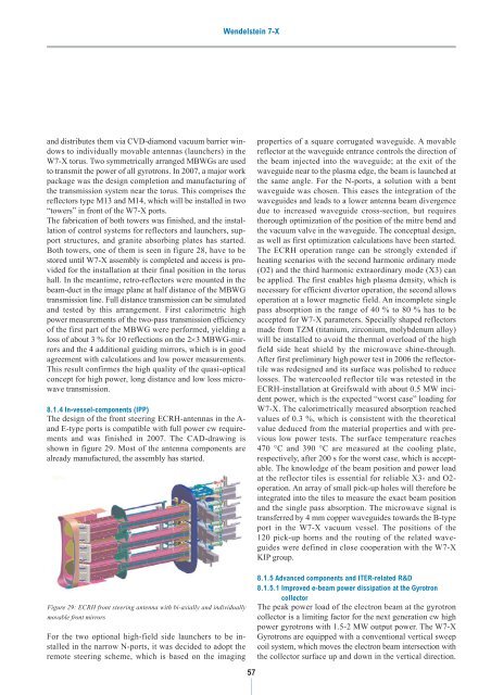
The design of the front steering ECRH-antennas in the Aand<br />
E-type ports is compatible with full power cw requirements<br />
and was finished in <strong>2007</strong>. The CAD-drawing is<br />
shown in figure 29. Most of the antenna components are<br />
already manufactured, the assembly has started.<br />
Figure 29: ECRH front steering antenna with bi-axially and individually<br />
movable front mirrors<br />
For the two optional high-field side launchers to be installed<br />
in the narrow N-ports, it was decided to adopt the<br />
remote steering scheme, which is based on the imaging<br />
Wendelstein 7-X<br />
57<br />
properties of a square corrugated waveguide. A movable<br />
reflector at the waveguide entrance controls the direction of<br />
the beam injected into the waveguide; at the exit of the<br />
waveguide near to the plasma edge, the beam is launched at<br />
the same angle. For the N-ports, a solution with a bent<br />
waveguide was chosen. This eases the integration of the<br />
waveguides and leads to a lower antenna beam divergence<br />
due to increased waveguide cross-section, but requires<br />
thorough optimization of the position of the mitre bend and<br />
the vacuum valve in the waveguide. The conceptual design,<br />
as well as first optimization calculations have been started.<br />
The ECRH operation range can be strongly extended if<br />
heating scenarios with the second harmonic ordinary mode<br />
(O2) and the third harmonic extraordinary mode (X3) can<br />
be applied. The first enables high plasma density, which is<br />
necessary for efficient divertor operation, the second allows<br />
operation at a lower magnetic field. An incomplete single<br />
pass absorption in the range of 40 % to 80 % has to be<br />
accepted for W7-X parameters. Specially shaped reflectors<br />
made from TZM (titanium, zirconium, molybdenum alloy)<br />
will be installed to avoid the thermal overload of the high<br />
field side heat shield by the microwave shine-through.<br />
After first preliminary high power test in 2006 the reflectortile<br />
was redesigned and its surface was polished to reduce<br />
losses. The watercooled reflector tile was retested in the<br />
ECRH-installation at Greifswald with about 0.5 MW incident<br />
power, which is the expected “worst case” loading for<br />
W7-X. The calorimetrically measured absorption reached<br />
values of 0.3 %, which is consistent with the theoretical<br />
value deduced from the material properties and with previous<br />
low power tests. The surface temperature reaches<br />
470 °C and 390 °C are measured at the cooling plate,<br />
respectively, after 200 s for the worst case, which is acceptable.<br />
The knowledge of the beam position and power load<br />
at the reflector tiles is essential for reliable X3- and O2operation.<br />
An array of small pick-up holes will therefore be<br />
integrated into the tiles to measure the exact beam position<br />
and the single pass absorption. The microwave signal is<br />
transferred by 4 mm copper waveguides towards the B-type<br />
port in the W7-X vacuum vessel. The positions of the<br />
120 pick-up horns and the routing of the related waveguides<br />
were defined in close cooperation with the W7-X<br />
KIP group.<br />
8.1.5 Advanced components and ITER-related R&D<br />
8.1.5.1 Improved e-beam power dissipation at the Gyrotron<br />
collector<br />
The peak power load of the electron beam at the gyrotron<br />
collector is a limiting factor for the next generation cw high<br />
power gyrotrons with 1.5-2 MW output power. The W7-X<br />
Gyrotrons are equipped with a conventional vertical sweep<br />
coil system, which moves the electron beam intersection with<br />
the collector surface up and down in the vertical direction.