

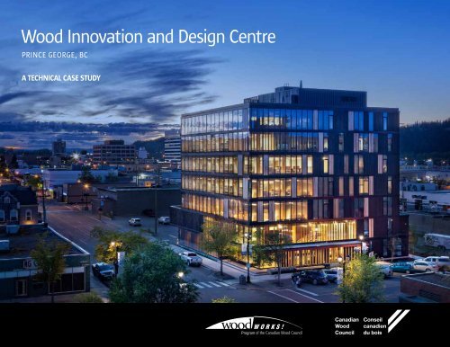
Wood Innovation and Design Centre
YWm8X
YWm8X

You also want an ePaper? Increase the reach of your titles
YUMPU automatically turns print PDFs into web optimized ePapers that Google loves.
<strong>Wood</strong> <strong>Innovation</strong> <strong>and</strong> <strong>Design</strong> <strong>Centre</strong><br />
PRINCE GEORGE, BC<br />
A TECHNICAL CASE STUDY
CONTENTS<br />
WIDC ENVIRONMENTAL<br />
BUILDING DECLARATION<br />
INTRODUCTION.........................................................................................3<br />
BACKGROUND...........................................................................................4<br />
CONSTRUCTION SEQUENCE........................................................................6<br />
CONNECTIONS...........................................................................................7<br />
Foundation..................................................................................7<br />
Column-to-Column........................................................................8<br />
Beam Framing..............................................................................9<br />
CLT Panels for Elevator, Stair <strong>and</strong> Mechanical Cores...................... 10<br />
Miscellaneous Connections ......................................................... 10<br />
FLOOR SYSTEM........................................................................................ 11<br />
FIRE SAFETY............................................................................................. 12<br />
Fire Safety During Construction.................................................... 12<br />
In-service Fire Safety................................................................... 13<br />
Elevator Shaft............................................................................. 14<br />
Stairwells .................................................................................. 15<br />
BUILDING ENVELOPE................................................................................ 16<br />
Window Mullions........................................................................ 18<br />
SOUND PRIVACY...................................................................................... 19<br />
STRUCTURAL WOOD PRODUCTS................................................................ 20<br />
Cross-laminated timber (CLT)....................................................... 20<br />
Glulam....................................................................................... 20<br />
Laminated veneer lumber (LVL) ................................................... 20<br />
Parallel str<strong>and</strong> lumber (PSL) ........................................................ 20<br />
LESSONS LEARNED .................................................................................. 21<br />
ADDITIONAL INFORMATION ..................................................................... 22<br />
PROJECT TEAM ........................................................................................ 23<br />
TIMBER INSTALLER AND MAJOR SUPPLIERS .............................................. 23<br />
SPONSORS ............................................................................................. 24<br />
CREDITS<br />
Construction images: naturally:wood® | Paul Alberts unless otherwise noted<br />
Front Cover <strong>and</strong> Back Cover: Ed White Photography<br />
Images of completed building: Ema Peter Photography (pages 4, 15, 22) Ed White Photography (pages 8, 14, 19-22)<br />
Renderings: Michael Green Architecture Inc. <strong>and</strong> Structurlam as shown<br />
Similar to Environmental Product Declarations (EPD)<br />
that provide information on components used in the<br />
manufacture of construction materials <strong>and</strong> products,<br />
Environmental Building Declarations (EBD) are now<br />
being developed <strong>and</strong> used in Europe. EBD information<br />
is presented in a table that identifies the impacts on<br />
the environment <strong>and</strong> human health across a range of<br />
categories, <strong>and</strong> applies them to the Life Cycle Analysis<br />
(LCA) of whole buildings. LCA is a cradle-to-grave analysis<br />
of the material effects of structure, envelope <strong>and</strong> interior<br />
partition assemblies, <strong>and</strong> operating energy <strong>and</strong> water<br />
use, over a 50-year period.<br />
The <strong>Wood</strong> <strong>Innovation</strong> <strong>and</strong> <strong>Design</strong> <strong>Centre</strong> is one of the<br />
first buildings in North America for which an EBD has<br />
been prepared. The whole-building LCA was conducted<br />
by the ATHENA Sustainable Materials Institute <strong>and</strong><br />
was commissioned to identify the environmental<br />
performance of the building.<br />
The assessment was conducted in conformance with<br />
the Committee for European St<strong>and</strong>ardization (CEN)<br />
st<strong>and</strong>ard EN 15978 which, while European in scope,<br />
is quickly becoming the st<strong>and</strong>ard for whole-building<br />
LCA worldwide. ATHENA applied its North American<br />
interpretation of EN 15978 to meet the purpose of the<br />
assessment for the WIDC.<br />
Seventeen indicators covering environmental impacts,<br />
resource use, waste, <strong>and</strong> output flows leaving the<br />
system were evaluated. In addition, various contribution<br />
<strong>and</strong> sensitivity analyses were carried out, <strong>and</strong> are<br />
presented along with additional information, including<br />
the impact of carbon sequestration, the substitution<br />
of wood for concrete, <strong>and</strong> other avoided impacts <strong>and</strong><br />
burdens occurring beyond the 50-year life cycle.<br />
While the EBD presents only the objective findings of<br />
the analysis, the ATHENA organization has stated that<br />
the “public disclosure of its embodied environmental<br />
footprint puts WIDC on the leading edge.”<br />
The EBD <strong>and</strong> the full ATHENA report are available at:<br />
http://www.athenasmi.org/news-item/<br />
new-environmental-building-declaration-for-widc/<br />
2
INTRODUCTION<br />
With a height of 29.5 metres, the <strong>Wood</strong> <strong>Innovation</strong> <strong>and</strong> <strong>Design</strong><br />
<strong>Centre</strong> (WIDC) is the tallest contemporary wood building in<br />
North America. Located in the city of Prince George in northern<br />
British Columbia, the WIDC was conceived as a showcase for local<br />
wood products <strong>and</strong> as a demonstration of the province’s growing<br />
expertise in the design <strong>and</strong> construction of large wood buildings.<br />
LANE<br />
The building has eight levels (six storeys, plus a ground floor mezzanine <strong>and</strong> a rooftop<br />
mechanical penthouse). The lower levels will accommodate faculty <strong>and</strong> students enrolled in<br />
the new Master of Engineering in Integrated <strong>Wood</strong> <strong>Design</strong> (MEng), to be launched by the<br />
University of Northern British Columbia (UNBC) in January 2016 <strong>and</strong> the new <strong>Centre</strong> for <strong>Design</strong><br />
<strong>Innovation</strong> <strong>and</strong> Entrepreneurship to be launched by Emily Carr University of Art <strong>and</strong> <strong>Design</strong> in fall<br />
2016. Academic facilities include a research/teaching lab that will support the design, fabrication<br />
<strong>and</strong> testing of wood products; a 75-seat lecture theatre; classrooms; a student lounge; gathering<br />
<strong>and</strong> meeting areas; <strong>and</strong> a learning resource centre. The upper floors will provide office space for<br />
public <strong>and</strong> private sector organizations associated with the wood industry.<br />
Over the long term, the WIDC will advance wood education <strong>and</strong> innovation in the province,<br />
enhance expertise in wood manufacturing, product development <strong>and</strong> engineering – all of<br />
which will help to exp<strong>and</strong> opportunities for international exports of products <strong>and</strong> services.<br />
In addition, its striking presence in the heart of the city will assist in the revitalization of<br />
downtown Prince George.<br />
This case study describes the most important innovations that were implemented to meet<br />
design <strong>and</strong> safety criteria in what is a new class of buildings for British Columbia. These<br />
innovations included:<br />
• A set of site-specific regulations to ensure life safety <strong>and</strong> structural integrity;<br />
• The use of vertical cross-laminated timber (CLT) elements (including mechanical,<br />
elevator <strong>and</strong> stair shafts) to provide lateral stability to the structure;<br />
• The use of double layer CLT floors to meet structural requirements <strong>and</strong> contribute<br />
to acoustic isolation <strong>and</strong> efficient services distribution;<br />
• The use of superimposed (end grain-to-end grain bearing) columns to control<br />
shrinkage over the height of the building; <strong>and</strong>,<br />
• The use of high strength proprietary connectors to speed construction <strong>and</strong><br />
improve structural performance.<br />
Figure 1 shows the siting of the WIDC in downtown Prince George (right).<br />
ENTRANCE<br />
N<br />
Figure 1: WIDC site plan<br />
Michael Green Architecture Inc.<br />
FIFTH AVENUE<br />
ENTRANCE<br />
ENTRANCE<br />
GEORGE STREET<br />
3
BACKGROUND<br />
British Columbia has been a leader in North America<br />
in the implementation of building regulations that<br />
permit the greater use of wood construction in<br />
larger <strong>and</strong> taller buildings.<br />
In 2009, the BC Building Code was amended to permit wood construction of up<br />
to six storeys for residential occupancies. Elsewhere in North America, several<br />
other provinces <strong>and</strong> states, as well as the model National Building Code of<br />
Canada, are conducting their own research, with the intention of following<br />
British Columbia’s lead.<br />
The WIDC was designed to the 2012 BC Building Code as amended by the<br />
<strong>Wood</strong> <strong>Innovation</strong> <strong>Design</strong> <strong>Centre</strong> Regulation (the site-specific regulations<br />
as noted previously). Combined with research <strong>and</strong> testing, the regulations<br />
were developed to provide code-equivalent levels of safety to those required<br />
for similar buildings of non-combustible construction. The major criteria<br />
established for the WIDC were:<br />
• A building area of not more than 1,125 m 2 ;<br />
• A building height of six storeys, <strong>and</strong> floor areas that together total<br />
not more than 4,850 m 2 ;<br />
• Not more than 30m in height measured from grade to the highest<br />
point of the uppermost roof; <strong>and</strong>,<br />
• Major occupancy classifications consisting of:<br />
• First <strong>and</strong> second storeys – Group A, Division 2 assembly<br />
occupancy or Group D business or personal services occupancies;<br />
• Third to sixth storeys – Group D business <strong>and</strong> personal service<br />
occupancies.<br />
Financed by the Province of British Columbia, the design <strong>and</strong> construction<br />
process was fast-tracked to meet funding criteria, <strong>and</strong> to make the most<br />
of the region’s short construction season. This meant that detailed design<br />
of the superstructure was still in progress when work began on site.<br />
The glazed curtain wall<br />
is interspersed with a<br />
combination of untreated<br />
<strong>and</strong> charred Western red<br />
cedar panels<br />
4
<strong>Design</strong> began in early 2013, <strong>and</strong> construction of the concrete raft slab<br />
foundation began in August of the same year. This was closely followed<br />
by the arrival on site of the first wood members in September. By the<br />
end of October 2014, the building was substantially complete <strong>and</strong> the<br />
UNBC <strong>and</strong> common areas of the building were ready for occupancy.<br />
The upper floors were left as open, unfinished areas, to be let out as<br />
suitable tenants are secured.<br />
In addition to utilizing a variety of locally manufactured engineered<br />
wood products, the WIDC incorporates numerous other sustainable<br />
design strategies, <strong>and</strong> has achieved LEED (Leadership in Energy <strong>and</strong><br />
Environmental <strong>Design</strong>) Gold certification.<br />
The primary structure is an innovative combination of glulam post-<strong>and</strong>beam<br />
frame construction, a custom-designed CLT floor system, <strong>and</strong> CLT<br />
elevator, stair <strong>and</strong> mechanical shafts. Concrete was used only for the<br />
ground floor slab <strong>and</strong> for the floor of the penthouse mechanical room.<br />
Wherever possible, the wood structural members were left exposed.<br />
Appearance-grade Douglas fir was used for the bottom lamination of<br />
the CLT floors (visible from below), <strong>and</strong> these were given a clear coat<br />
finish.<br />
The building is balloon-framed, meaning that the columns are<br />
superimposed one above the other, with end grain-to-end grain<br />
bearing. The beams then frame into the sides of the columns; there<br />
is no cross grain in the vertical section of the building. This technique<br />
minimizes cumulative vertical shrinkage that could otherwise impact<br />
the performance of the structure. The building systems are repeatable<br />
<strong>and</strong> exp<strong>and</strong>able to other building types <strong>and</strong> sizes.<br />
The building envelope is a combination of glazing installed in vertically<br />
laminated veneer lumber (LVL) mullions <strong>and</strong> structural insulated<br />
panels (SIPs) clad with natural or charred Western red cedar siding.<br />
Innovative combination of<br />
glulam post-<strong>and</strong>-beam frame<br />
construction <strong>and</strong> customdesigned<br />
CLT floor system<br />
5
CONSTRUCTION SEQUENCE<br />
After completion of the concrete slab foundation, building construction progressed as shown in Figure 2 (below).<br />
1 The lateral-load resistance is primarily<br />
provided by the elevator <strong>and</strong> stair core walls,<br />
which consist of CLT panels. The shear walls<br />
are anchored to the foundations using a<br />
combination of shear brackets <strong>and</strong> holddown<br />
anchors.<br />
2 The structure is a glulam post-<strong>and</strong>-beam<br />
system with built-up CLT floor panels.<br />
Glulam beams frame into glulam columns<br />
using proprietary aluminum dovetail Pitzl<br />
connectors.<br />
Red-stained plywood feature wall during construction<br />
3 Staggered CLT floor panels are installed.<br />
Upper floor columns bear directly on columns<br />
from the floor below. Laminated veneer<br />
lumber (LVL) wind columns <strong>and</strong> structural<br />
insulated panels (SIPs) followed on each floor.<br />
4 The building envelope is set in place<br />
including curtain wall glazing <strong>and</strong> wood<br />
cladding. The roof enclosed the building<br />
with mechanical penthouse on top. Building<br />
is now enclosed for services installation <strong>and</strong><br />
interior partition framing to begin.<br />
5 The British Columbia Building Code<br />
restricts the height of wooden nonresidential<br />
buildings to four storeys. A<br />
unique site-specific regulation allows a<br />
mass timber building of six storeys to be<br />
built for assembly <strong>and</strong> office occupancies.<br />
Installation of glulam column-to-column connector<br />
Figure 2: Construction sequence<br />
Michael Green Architecture Inc.<br />
6
CONNECTIONS<br />
Foundation<br />
The foundation for the WIDC is a reinforcedconcrete<br />
raft slab that varies in thickness from<br />
400 to 600mm (16 to 24 in.). Baseplates for the<br />
glulam columns <strong>and</strong> CLT walls were carefully<br />
positioned <strong>and</strong> cast into the slab. The contractor<br />
surveyed the location of all baseplates before,<br />
during <strong>and</strong> after the pour. This thoroughness<br />
paid off, as only one baseplate out of 80 needed<br />
to be readjusted.<br />
For the superstructure, ETABS software (a 3D<br />
object-based modelling <strong>and</strong> visualization tool<br />
that enables designers to quickly explore <strong>and</strong><br />
compare alternate design approaches) was used<br />
to model the lateral system.<br />
As a result of this analysis, the design team<br />
decided to use a CLT core for the building<br />
(comprising elevator <strong>and</strong> stair shafts <strong>and</strong> the<br />
mechanical service chase). The panels of these<br />
core elements are connected using self-tapping<br />
screws to create continuous shear walls. The<br />
shear walls are anchored to the foundations<br />
using a combination of shear brackets connected<br />
to the panels with self-tapping screws <strong>and</strong> holddown<br />
anchors (photo: right) connected to the<br />
panels using the ductile HSK system.<br />
Placement of column for welding to the baseplate<br />
Two types of connections were used to secure<br />
the slab-level columns to the concrete slab. Most<br />
used an embedded plate cast into the concrete<br />
slab (as described above) <strong>and</strong> a matching<br />
column base with a thick vertical fin plate<br />
(beveled for welding) that was factory installed<br />
into the base of the glulam column using<br />
self-tapping screws or epoxied HSK connectors<br />
(photos: far right). This allowed for precise<br />
placement of the columns. Where anchor bolts<br />
were used, the base connection was designed<br />
as a pedestal, <strong>and</strong> detailed to permit factory<br />
installation to the base of the glulam columns.<br />
CLT core panel showing a tie-down connector<br />
CLT core panel showing a tie-down connector<br />
7
Column-to-Column<br />
As previously noted, the WIDC is constructed<br />
using a balloon-framed system. This means the<br />
columns are continuous (but spliced at each<br />
floor) <strong>and</strong> the beams are attached to the sides of<br />
the columns (Figure 3).<br />
As well as reducing vertical shrinkage to only<br />
1mm per floor, this removes the beams <strong>and</strong><br />
floor system from the load path of the columns.<br />
Because the crushing strength of wood<br />
perpendicular-to-grain is only one tenth of that<br />
parallel-to-grain, this strategy is critical for the<br />
successful design of taller wood buildings.<br />
The hold-down nuts for the column-to-column<br />
connections were tightened using a special<br />
tool made from a magnet <strong>and</strong> a ratcheting box<br />
wrench. At completion, the access holes were<br />
filled with a wood plug to conceal the bolts<br />
(photo: right).<br />
Bearing plate<br />
15.9 mm ( in.)<br />
diameter threaded<br />
rods pre-epoxied<br />
in glulam column<br />
in glulam column<br />
Sleeve inserted into glulam<br />
column before lowering<br />
column.<br />
column. Nuts tightened Nuts tightened <strong>and</strong> hole in<br />
<strong>and</strong> hole in column<br />
column plugged after installation<br />
plugged after installation<br />
Pitzel Pitzl connectors<br />
Figure 3: Exploded view of a typical<br />
column-to-column connection <strong>and</strong><br />
the attachment of beams<br />
Credit: Structurlam<br />
DETAIL 2/S30<br />
EXPLODED<br />
<strong>Wood</strong> plug installed to conceal the<br />
column-to-column connection<br />
8
Beam Framing<br />
The glulam beams frame into the glulam<br />
columns (see Figure 3 on previous page <strong>and</strong><br />
Figure 4 below) using dovetail connectors,<br />
allowing the columns to run continuously<br />
from the foundation to the roof. The<br />
dovetail connectors (Pitzl) were installed at<br />
the glulam plant (photo: far right).<br />
Typically, frame elements comprising two<br />
columns <strong>and</strong> one beam were assembled<br />
in a horizontal position <strong>and</strong> then erected<br />
(photo: below).<br />
Installation of<br />
two columns<br />
with beam<br />
already affixed<br />
Figure 4<br />
Credit: Structurlam<br />
5 th Avenue<br />
Front<br />
entry<br />
George Street<br />
Factory installation of dovetail connector to a beam end<br />
Credit: Swanky Photography<br />
9
CLT Panels for Elevator,<br />
Stair <strong>and</strong> Mechanical Cores<br />
The floor system was supported at the core walls (photo: below<br />
top) using laminated str<strong>and</strong> lumber (LSL) ledgers <strong>and</strong> self-tapping<br />
screws (photo: below bottom). The lower screws were oriented at<br />
45° to capitalize on their strength when loaded in withdrawal.<br />
Miscellaneous Connections<br />
In addition to the connectors described in the preceding sections,<br />
other st<strong>and</strong>ard types were used as shown (photos: below).<br />
LSL ledger supporting the floor<br />
at the vertical CLT core wall<br />
Floor-to-beam<br />
bracket connection<br />
Angle clips <strong>and</strong><br />
self-tapping screws to<br />
support the top of<br />
a window mullion<br />
Self-tapping<br />
screws readied<br />
for attaching<br />
a ledger to the<br />
CLT core<br />
Stock beam hanger<br />
Angle clips at core<br />
CLT intersection<br />
Steel beam screwed<br />
into a pocket in the<br />
core CLT panel<br />
10
FLOOR SYSTEM<br />
The WIDC floor system consists of two layers of CLT panels, running parallel<br />
to each other <strong>and</strong> connected together compositely to form a corrugated<br />
structural section. The panels in each layer are laid with gaps between them,<br />
creating a series of chases in which services can be concealed.<br />
The chases in the upper <strong>and</strong> lower layers enable pipes to be laid within the cavities (see Figure 5). This<br />
arrangement leaves the underside of the CLT panels exposed.<br />
Plywood covers were installed over the upper panel cavities immediately after CLT installation to provide<br />
an even walking surface (photo: below left of centre). They were removed as required to install services <strong>and</strong><br />
then acoustic subflooring <strong>and</strong> finish flooring were installed (photo: below left of centre). Cavities between the<br />
lower CLT (ceiling) panels were covered by removable slatted wood panels (photo: below left).<br />
Where the upper <strong>and</strong> lower CLT panels intersect, they are joined together using the HSK connection system.<br />
This involves short saw-cuts through the edges of the panels creating a continuous vertical kerf. A perforated<br />
metal plate is then placed in the saw-cut <strong>and</strong> the void is filled with epoxy glue (photos: below centre). The<br />
result is an extremely strong <strong>and</strong> elastic connection that creates a composite structure in which the upper<br />
<strong>and</strong> lower panels act together.<br />
Foam was injected at the ends of the saw-cuts to seal any discontinuities in the interior of the CLT panels. This<br />
was done to prevent leakage of adhesive <strong>and</strong> to ensure that the correct amount of epoxy had been used. The<br />
epoxy was injected from the top of the floor with the injection nozzle located at the bottom of the saw-cut to<br />
push air up <strong>and</strong> out of the cavity. Visual verification <strong>and</strong> volume measurements were used to ensure the HSK<br />
perforated plates were fully encased with epoxy.<br />
Figure 5: Section through the floors<br />
Credit: Michael Green Architecture Inc.<br />
Ceiling cavities in the Level 1<br />
demonstration area contain lighting<br />
<strong>and</strong> fire suppression systems concealed<br />
by a removable wood-slat finish<br />
Ceiling showing the underside of overlapping<br />
CLT panels <strong>and</strong> the service chases on the<br />
floor with plywood covers in place<br />
Saw kerf (left of the worker)<br />
ready for HSK plate insertion<br />
Epoxy injection for<br />
securing the HSK plate<br />
Insertion of HSK plate<br />
Installation of services below CLT floor<br />
11
FIRE SAFETY<br />
<strong>Design</strong> for fire safety was<br />
based on the BC Building<br />
Code <strong>and</strong> the site-specific<br />
regulation created for<br />
the <strong>Wood</strong> <strong>Innovation</strong> <strong>and</strong><br />
<strong>Design</strong> <strong>Centre</strong>.<br />
Fire Safety During Construction<br />
The risks <strong>and</strong> hazards on a construction site<br />
differ in both nature <strong>and</strong> potential impact to<br />
those of a completed building because they<br />
can occur at a time when the safeguards that<br />
are designed to be part of the completed<br />
building are not yet in place. Building codes<br />
focus on protecting the occupants of completed<br />
buildings. In addition to meeting any provincial<br />
regulations for fire safety during construction,<br />
there are best practices that should be applied.<br />
To this end, the Canadian <strong>Wood</strong> Council has<br />
developed best practices 1 for buildings under<br />
construction. For example, 24-hour security<br />
is not usually a code requirement, but is a<br />
way of reducing the risk of v<strong>and</strong>alism, theft or<br />
arson, <strong>and</strong> for detecting problems before they<br />
grow out of control. In the case of the WIDC,<br />
the contractor, PCL, worked with the Prince<br />
George Fire Department to develop a series<br />
of fire safety practices to be implemented<br />
during construction. Twenty-four-hour security<br />
was provided, <strong>and</strong> st<strong>and</strong>-pipes for firefighting<br />
were installed as building height increased. In<br />
addition, ‘hot works’ were minimized during<br />
construction; for example, crimped pipe<br />
connections were used in lieu of soldering to<br />
eliminate the possibility of an accidental fire.<br />
1<br />
Fire Safety <strong>and</strong> Security (for construction sites) <strong>and</strong> technical bulletins about fire safety, durability, building<br />
performance, insurance, case studies, managing movement <strong>and</strong> other topics are available from the<br />
Canadian <strong>Wood</strong> Council, http://cwc.ca/publications/<br />
Fire stopping was required at the joints between CLT panels in order to prevent the passage<br />
of fire <strong>and</strong> smoke (see page 14)<br />
12
In-service Fire Safety<br />
It has long been recognized that large timber<br />
members have an inherent fire resistance<br />
because of their slow <strong>and</strong> predictable rate of<br />
charring when they are exposed to fire. This<br />
slow rate of char is approximately 40mm per<br />
hour, allowing large timber systems to maintain<br />
significant structural capacity for an extended<br />
duration during a fire. New massive engineered<br />
wood panel <strong>and</strong> beam products, such as crosslaminated<br />
timber (CLT), parallel str<strong>and</strong> lumber<br />
(PSL) <strong>and</strong> others can take advantage of this<br />
attribute because of their large cross-section. Fire<br />
performance is further enhanced through the use<br />
of concealed connectors, whereby structural or<br />
non-structural wood elements provide protection<br />
to the vulnerable steel components.<br />
The fire design of the CLT components at<br />
WIDC is based on the methodology set out in<br />
the Canadian CLT H<strong>and</strong>book, which includes<br />
a chapter titled “Fire performance of crosslaminated<br />
timber assemblies”. A subsequent<br />
US edition provides further guidance on the<br />
performance of joints between CLT panels.<br />
The calculation methodology is based on the<br />
st<strong>and</strong>ard fire exposure <strong>and</strong> is a means for<br />
predicting the expected fire resistance that would<br />
be determined when testing to CAN/ULC-S101.<br />
The h<strong>and</strong>book uses the reduced cross-section<br />
method to estimate the residual capacity of<br />
structural members after some duration of fire<br />
exposure. A char depth is calculated based on<br />
the fire exposure time, <strong>and</strong> an additional depth is<br />
subtracted to account for the heated wood that<br />
has lost some strength, leaving a reduced crosssection.<br />
The capacity of the reduced cross-section<br />
can then be determined using the full design<br />
strength of the member.<br />
In addition to supporting the structural loads<br />
in the event of a fire, it was also required that<br />
the mass-timber panel assemblies at WIDC resist<br />
the passage of flames <strong>and</strong> hot gases, <strong>and</strong> limit<br />
the temperature rise on the unexposed surface<br />
of the assembly in order to prevent fire spread<br />
from one compartment to another. Since wood<br />
is an effective insulator, <strong>and</strong> CLT is manufactured<br />
by laminating together individual pieces of<br />
lumber, a CLT assembly will always experience<br />
either structural failure or integrity failure before<br />
thermal failure can occur. Also, as CLT panels<br />
tend to be sealed well (through the thickness<br />
of the panel), in part because of the use of<br />
polyurethane adhesives which foam to fill voids<br />
during manufacturing, the main concern with<br />
respect to integrity failure is the joints between<br />
adjacent CLT panels or between assemblies (e.g.,<br />
wall-to-floor joints).<br />
While it was the site-specific regulation that<br />
allowed for this tall wood building to be<br />
constructed, it was the BC Building Code that<br />
governed the fire separations applicable between<br />
spaces <strong>and</strong> at the building core elements (stair,<br />
elevator shaft). In the case of the WIDC, the<br />
requirement for these separations was one hour.<br />
Engineering judgment, supported by existing fire<br />
test data, showed that the structural CLT walls,<br />
stringer panels, <strong>and</strong> l<strong>and</strong>ing floors within the<br />
stair were appropriately sized to provide that onehour<br />
separation without requiring additional fire<br />
protection elements such as gypsum drywall.<br />
The design criteria for a typical floor assembly<br />
are shown in Table 1 <strong>and</strong> those for a typical<br />
wall assembly in Table 2. In both cases, the CLT<br />
assemblies meet the one-hour fire-resistance<br />
requirements based on the calculation method.<br />
Table 1: Sample CLT floor assembly<br />
Assembly Location Specifications Max. live load Max. dead load Floor span Calculated<br />
structural fireresistance<br />
rating<br />
CLT Floor 2<br />
Storeys<br />
3-6<br />
5-ply bottom<br />
CLT, 3 ply top<br />
Grade V2, 200<br />
mm overlap<br />
2.4 kPa<br />
2.4 kPa, (1.6<br />
kPa on 3-ply)<br />
Table 2: Sample CLT wall assembly requiring a fire-resistance rating<br />
5.8 m 1 hr.<br />
Assembly Location Specifications Max. live load Max. dead load Wall height Calculated<br />
structural fireresistance<br />
rating<br />
CLT Wall 1<br />
All floors<br />
5-ply CLT,<br />
Grade V2,<br />
150 mm half<br />
lap joint<br />
200 kN/m<br />
70 kN/m<br />
3.5 m<br />
(pinned<br />
end<br />
conditions)<br />
1.5 hrs.<br />
13
Since there were no prescribed fire stop<br />
systems for penetrations in CLT assemblies, all<br />
penetrations <strong>and</strong> major joint configurations were<br />
tested in accordance with CAN/ULC-S115 Fire<br />
Tests of Fire Stop Systems as required by the BC<br />
Building Code.<br />
The site-specific regulation required the provision<br />
of direct access for firefighting from the outside<br />
of the building at every level less than 25m<br />
above grade. Specifically, this meant at least<br />
one unobstructed window or access panel being<br />
provided for each 15m of wall, in at least one<br />
wall facing a street or lane. Consequently, every<br />
level of the WIDC, starting from Level 2, has two<br />
fire department access doors facing George Street<br />
(photo: below left).<br />
The elevator shafts, exit stair <strong>and</strong> exit corridor<br />
walls, scissor-stair dividing walls, <strong>and</strong> scissorstair<br />
floor assemblies required a one-hour fire<br />
separation. In addition, the scissor-stair walls,<br />
floor assemblies <strong>and</strong> the shafts around the<br />
st<strong>and</strong>pipe risers (at Level 1) were constructed to<br />
prevent the migration of smoke from one scissor<br />
stair to the other.<br />
This required careful design <strong>and</strong> proper sealing<br />
of panel-to-panel joints. Joint designs were<br />
evaluated by the team for their constructability<br />
<strong>and</strong> effectiveness in creating a smoke barrier.<br />
The most promising joint designs were then<br />
laboratory tested to confirm their effectiveness.<br />
Elevator Shaft<br />
The elevator shaft is comprised of CLT panels<br />
installed vertically, like other elements of the<br />
‘core’ structure. The inside surfaces were sitetreated<br />
with a ULC-listed intumescent coating,<br />
a treatment that exp<strong>and</strong>s in fire to provide a<br />
degree of fire protection (photo: below right). The<br />
treated CLT surfaces have a flame-spread rating<br />
of not more than 25. This rating is based on thin<br />
samples of Douglas fir, but more recent testing<br />
has shown that the resistance to flame spread is<br />
better for intumescent coatings applied to CLT<br />
panels due to their mass.<br />
To function effectively, an elevator must be able<br />
to cope with the anticipated vertical movement<br />
in a tall building. The design precautions taken<br />
to minimize shrinkage (as outlined previously)<br />
appear to have successfully addressed any such<br />
problems on the WIDC project. Based on data<br />
from sensors placed in the shaft, this movement<br />
did not exceed the design tolerance. However,<br />
service technicians have had to reduce the rail<br />
sensor sensitivity to improve reliability.<br />
One of the two tiers of fire access doors integrated into the George Street façade<br />
The CLT elevator shaft did not require any special acoustic treatment as it is not adjacent to noise sensitive areas<br />
14
Stairwells<br />
Emergency egress from the WIDC is provided<br />
by double-scissor stairways (photo: far right).<br />
As with the elevator shaft, the CLT walls <strong>and</strong><br />
ceilings in the exit stairs were treated with a<br />
fire-retardant coating to reduce the flame spread<br />
rating to 25.<br />
To ensure that smoke could not migrate from<br />
one scissor stair to the other, it was necessary to<br />
drill a small hole <strong>and</strong> apply sealant at each board<br />
joint in the CLT stair shaft wall, immediately<br />
above <strong>and</strong> below the stringer <strong>and</strong> l<strong>and</strong>ing panels.<br />
This sealed the small cracks that typically form<br />
between the boards on the outer layer of CLT<br />
panels due to shrinkage.<br />
Building the feature stair: installation of LVL risers on the inclined LVL stringer panel<br />
Finished feature stair in the main lobby<br />
Stairwell with CLT walls, ceiling <strong>and</strong> floor<br />
15
BUILDING ENVELOPE<br />
The primary function of the building envelope is to mitigate or harness the environmental forces acting upon it,<br />
<strong>and</strong> to maintain a comfortable thermal, visual <strong>and</strong> acoustic environment within the building.<br />
The most important environmental considerations<br />
for the WIDC project were:<br />
The primary envelope assemblies for the WIDC are:<br />
1. Rain. The design objective was to<br />
incorporate rainscreen principles <strong>and</strong> to<br />
specify durable, high-quality materials<br />
to protect the wood structure <strong>and</strong> other<br />
moisture-sensitive components within<br />
the building envelope. <strong>Design</strong> of the<br />
water-shedding surface elements <strong>and</strong><br />
the secondary water-resistive barrier<br />
was critical to managing moisture<br />
penetration from rain <strong>and</strong> other sources.<br />
2. Condensation. The building enclosure<br />
consists of highly insulated wall,<br />
roof, <strong>and</strong> glazing assemblies. These<br />
assemblies, such as the triple-glazed<br />
thermally-broken curtain-wall system,<br />
already have a low risk of interior surface<br />
condensation. However, this risk was<br />
further mitigated by proper detailing of<br />
insulation to prevent thermal bridging<br />
at the wall <strong>and</strong> roof assemblies <strong>and</strong> the<br />
interfaces between the elements of the<br />
envelope.<br />
The potential for condensation due to<br />
vapour diffusion was managed through<br />
the use of vapour retardant elements on<br />
the interior face of the SIP panels, <strong>and</strong> a<br />
vapour barrier membrane within the roof.<br />
The potential for condensation<br />
resulting from air leakage was managed<br />
through the design <strong>and</strong> installation of<br />
a continuous <strong>and</strong> durable air barrier<br />
system <strong>and</strong> detailing of interface joints<br />
throughout the building envelope. The<br />
evaporation of moisture from incidental<br />
wetting or condensation is facilitated by<br />
the drained <strong>and</strong> ventilated rainscreen<br />
cladding system.<br />
3. Thermal comfort <strong>and</strong> temperature<br />
control. The building envelope<br />
incorporates highly insulated wall <strong>and</strong><br />
roof assemblies, <strong>and</strong> a triple-glazed,<br />
thermally-broken curtain-wall system,<br />
to achieve a higher level of thermal<br />
performance than that required by the<br />
building code. This high performance<br />
envelope is a key part of the overall<br />
energy efficiency strategy, <strong>and</strong> also<br />
contributes to LEED energy credits.<br />
1. Curtain-wall. This assembly consists of an<br />
aluminum curtain-wall system fastened<br />
to a vertically laminated LVL structural<br />
frame. The system is stick-built <strong>and</strong> siteglazed<br />
with triple-glazed units that are<br />
argon filled with low-e coatings.<br />
2. Cedar-clad rainscreen walls. The wall<br />
assembly consists of structural insulated<br />
panels (SIPs) protected on the exterior<br />
with a high-performance, liquid-silicone<br />
air <strong>and</strong> moisture barrier membrane.<br />
All joints between the SIPs are sealed<br />
at the interior <strong>and</strong> exterior side <strong>and</strong><br />
are insulated where gaps occur, for<br />
airtightness <strong>and</strong> condensation control.<br />
The SIP panels <strong>and</strong> critical barrier<br />
membranes are tied directly into the<br />
curtain-wall assembly. The panels are<br />
clad with a panelized tongue-<strong>and</strong>groove,<br />
fire-treated cedar cladding that<br />
have either a natural or charred finish,<br />
depending on their location.<br />
3. Roof. The roofs of the building are<br />
waterproofed with a two-ply torchon<br />
SBS-modified bitumen membrane.<br />
The main roof, mechanical room roof,<br />
elevator over-run roof <strong>and</strong> one of the<br />
lower roofs are of conventional design<br />
(assembles with membrane over<br />
insulation). An accessible lower roof <strong>and</strong><br />
ballasted area are of the ‘inverted’ type,<br />
consisting of a protected membrane roof<br />
assembly with insulation over top of the<br />
membrane.<br />
The roof assembly also incorporates an<br />
interior ventilated space above the CLT<br />
panels to facilitate drying, both during<br />
construction <strong>and</strong> in-service. This feature<br />
was incorporated to protect the CLT<br />
structure from deterioration in the event<br />
of excessive wetting during construction,<br />
or a roof leak after occupancy.<br />
4. Foundation. The below-grade<br />
construction includes the foundation<br />
walls <strong>and</strong> a slab-on-grade. The<br />
foundation waterproofing consists<br />
of a single-ply SBS waterproofing<br />
membrane that extends up above-grade<br />
<strong>and</strong> transitions to the air <strong>and</strong> moisture<br />
barrier membrane in the wall. There is<br />
no hydrostatic pressure on this project,<br />
so the foundation slab is poured over a<br />
heavy polyethylene vapour retarder <strong>and</strong><br />
drainage gravel.<br />
16
Installation of a cladding panel with charred siding<br />
SIP panels with air barrier membrane on the exterior face<br />
Mounting clip on SIP panel for mounting the cladding panel<br />
Along the footings, the general drainage<br />
provisions <strong>and</strong> perimeter drains were designed<br />
by the geotechnical <strong>and</strong> mechanical consultants.<br />
The insulation is installed vertically along<br />
the perimeter walls, conserving energy <strong>and</strong><br />
improving thermal comfort.<br />
The air barrier is a roller-applied liquid membrane<br />
(photo: top middle) that was tested on mock-up<br />
panels prior to installation.<br />
The cladding panels are made of Western red<br />
cedar siding. The siding was treated with fireretardant<br />
<strong>and</strong> then mounted on plywood backing<br />
panels (photo: top right). Some of the panels<br />
were left untreated to weather naturally. The<br />
siding on the other panels was factory-charred<br />
with a torch. The use of charred wood siding<br />
is a traditional construction practice used for<br />
centuries in many parts of the world including<br />
Finl<strong>and</strong>, Austria, Japan <strong>and</strong> Switzerl<strong>and</strong> (photos<br />
on following page).<br />
17
Western red cedar<br />
Untreated red cedar panels<br />
Charred cladding<br />
View of the curtain wall showing glazing <strong>and</strong> charred <strong>and</strong> natural Western red cedar siding<br />
The charring was done in two passes. After<br />
the first pass, a skin layer was removed by<br />
brushing. The second pass provided the<br />
desired char consistency <strong>and</strong> depth. Testing<br />
was done to ensure the charred siding<br />
maintained the required flame spread rating<br />
of 25 or less. The charred wood cladding<br />
increases durability by providing protection<br />
from insects <strong>and</strong> moisture, <strong>and</strong> results in<br />
a pleasing architectural appearance quite<br />
unique in North America.<br />
The charred siding was coated with a clear<br />
finish to improve moisture resistance <strong>and</strong><br />
to minimize smudging, a concern on Level<br />
1 where pedestrians could come into direct<br />
contact with the panels.<br />
Window Mullions<br />
Vertically laminated veneer lumber (LVL) was<br />
used for the vertical wind columns (mullions),<br />
with an applied aluminum veneer. The<br />
mullions support the triple-glazed curtainwall<br />
system (photos: right).<br />
LVL window mullion<br />
Window mullions after glazing installation<br />
18
SOUND PRIVACY<br />
There are two types of laboratory sound tests<br />
for measuring the sound that travels from<br />
one area of a building to another: Impact<br />
Insulation Class (IIC) <strong>and</strong> Sound Transmission<br />
Class (STC). IIC tests the ability to block<br />
impact sound by measuring the resistance to<br />
transmission of impact noise or structure-borne<br />
noise (simulating footfalls, objects dropped on<br />
the floor, etc.). STC evaluates the ability of a<br />
specific construction assembly to reduce the<br />
transmission of airborne sounds, such as voices,<br />
stereo systems <strong>and</strong> television, from one built<br />
space to another.<br />
Single <strong>and</strong> double layers of drywall, double-stud walls, insulation <strong>and</strong><br />
resilient channels were used to achieve the required sound transmission<br />
ratings for the walls. STC ratings were required to be more stringent<br />
in certain areas to meet UNBC’s own conference <strong>and</strong> lecture room<br />
requirements. To achieve these requirements, dropped noise-barrier<br />
ceilings consisting of double layers of drywall were installed in the<br />
designated rooms.<br />
Acoustic mats <strong>and</strong> carpet were installed over the CLT floors to reduce<br />
sound transmission. Successful in situ sound testing took place in<br />
August 2014. All of the floor/ceiling <strong>and</strong> wall assemblies satisfy the<br />
Apparent Sound Transmission Class (ASTC) requirements. In addition,<br />
all of the floor/ceiling Apparent Impact Insulation Class (AIIC)<br />
measurements satisfy the IIC requirements.<br />
A summary of select acoustic requirements <strong>and</strong> in situ test results is<br />
shown in Table 3 (right).<br />
The lecture theatre will be used for distance learning, so it had more stringent acoustic requirements than the<br />
other spaces in the building<br />
Table 3: Sample of acoustical requirements <strong>and</strong> results<br />
Assembly Source Room Receiver Room <strong>Design</strong> Requirement Measured<br />
Wall<br />
Floor<br />
Mechanical room<br />
<strong>Design</strong> classroom<br />
Lecture theatre<br />
<strong>Design</strong> classroom<br />
Project room<br />
Lecture theatre<br />
Project room<br />
Project room<br />
Faculty office<br />
Faculty office<br />
ASTC 47<br />
ASTC 47<br />
ASTC 42<br />
ASTC 42<br />
ASTC 42<br />
ASTC 48<br />
ASTC 48<br />
ASTC 60<br />
ASTC 53<br />
ASTC 47<br />
Floor<br />
Project room<br />
Faculty office<br />
Faculty office<br />
Lecture theatre<br />
<strong>Design</strong> classroom<br />
Project room<br />
FII 65<br />
FII 652<br />
AIIC 67<br />
AIIC 64<br />
AIIC 53<br />
19
STRUCTURAL WOOD PRODUCTS<br />
Cross-laminated timber (CLT)<br />
CLT is an engineered wood panel made by arranging <strong>and</strong> gluing layers of dimension<br />
lumber. Each layer is perpendicular to the next. CLT panels typically consist of<br />
three, five or seven layers. The dimensions of CLT panels are limited only by<br />
transportation constraints but they are typically up to 40 feet long <strong>and</strong> up to eight<br />
feet wide. CLT panels are typically used for floors, walls <strong>and</strong> roofs. In the WIDC, CLT<br />
panels were also used vertically for the core of the building – the mechanical <strong>and</strong><br />
elevator shafts, <strong>and</strong> core stairs.<br />
Glulam<br />
Glulam is made by gluing together laminations of solid-sawn lumbers that<br />
are specifically selected <strong>and</strong> positioned based on their structural strength<br />
<strong>and</strong> appearance characteristics. Glulam is typically used for beams <strong>and</strong><br />
columns <strong>and</strong> can be manufactured in curved sections. In the WIDC, glulam<br />
was used for the columns <strong>and</strong> most of the beams.<br />
Laminated veneer lumber (LVL)<br />
St<strong>and</strong>ard LVL is made from layers of veneer laid parallel to each other <strong>and</strong> bonded<br />
together with moisture-resistant adhesives. LVL is typically used for beams <strong>and</strong><br />
headers in residential <strong>and</strong> commercial construction. For the WIDC, vertically<br />
laminated LVL was used for the window mullions, entrance canopy, feature stairs,<br />
<strong>and</strong> other applications.<br />
Parallel str<strong>and</strong> lumber (PSL)<br />
Parallel str<strong>and</strong> lumber (PSL) Parallam® PSL is a high-strength structural composite<br />
lumber product manufactured by gluing str<strong>and</strong>s of wood together under heat<br />
<strong>and</strong> pressure. It is well-suited for use as beams <strong>and</strong> columns for post-<strong>and</strong>-beam<br />
construction, <strong>and</strong> can be used for long span beams when laminated into deep<br />
sections in both residential <strong>and</strong> commercial building construction. In the WIDC,<br />
Parallam® PSL beams were used in concealed locations to transfer column loads<br />
over the main level lecture theatre <strong>and</strong> research lab.<br />
20
LESSONS LEARNED<br />
This project was designed <strong>and</strong> constructed on a fast-track schedule. As a result, some timber work was done on site that could have<br />
more effectively been done in the factory. For example, some of the connectors were installed in the field – a slower <strong>and</strong> potentially<br />
less-accurate method of working.<br />
As noted by Nicola Logworks, prefabrication<br />
using computer numerical control (CNC)<br />
technology has the capability to precisely locate<br />
<strong>and</strong> mill openings, tapers, cuts <strong>and</strong> dimensions.<br />
In order to take full advantage of the benefits<br />
of using wood products <strong>and</strong> off-site capabilities<br />
for manufacturing, full building information<br />
modelling (BIM) <strong>and</strong> an integrated project<br />
delivery (IPD) system should be fully embraced<br />
from the start of a project.<br />
To minimize the possibility of errors, adequate<br />
time must be allocated during the design phase<br />
to ensure all members of the project team,<br />
including all design disciplines, fabricators <strong>and</strong><br />
manufacturers <strong>and</strong> all construction trades, have<br />
a common design platform to work from – that is<br />
to say, a single master 3D model.<br />
Engaging in a process that involves precise<br />
prefabrication of structural elements <strong>and</strong> the<br />
integration of a variety of building systems in the<br />
factory requires a high degree of commitment<br />
<strong>and</strong> co-operation from all members of the<br />
construction team. With wood, the realization of<br />
a durable, high quality project truly is a collective<br />
endeavour.<br />
Because most designers prefer to leave wood<br />
structures exposed for aesthetic reasons,<br />
structural elements need to be h<strong>and</strong>led<br />
with care to minimize physical damage <strong>and</strong><br />
discolouration from moisture or other sources.<br />
This generally includes protective wrapping<br />
during transportation <strong>and</strong> installation, but<br />
risks can be further reduced using ‘just in time’<br />
delivery that minimizes potential weather<br />
exposure <strong>and</strong> h<strong>and</strong>ling requirements on site. On<br />
the WIDC project, all the exposed structural wood<br />
elements (most of which were on the interior<br />
of the building) were left untreated during<br />
the construction phase. On completion of the<br />
structure, Nicola Logworks repaired, cleaned,<br />
prepped <strong>and</strong> applied all the finishes to the<br />
exposed wood elements.<br />
It was essential for the timber installer to ensure<br />
precise location of the vertical wood members on<br />
Level 1 to prevent cumulative errors. Concreteto-wood<br />
base anchor systems that allow some<br />
flexibility for horizontal <strong>and</strong> vertical adjustment<br />
should be used. This allows the timber installer<br />
to h<strong>and</strong>le the disparity between the tolerances<br />
allowed for concrete (± 24mm) <strong>and</strong> the tolerances<br />
attainable with wood (± 3mm depending on the<br />
length of the element). For example, threaded<br />
rods <strong>and</strong> supporting nuts, in combination with<br />
a base plate <strong>and</strong> grout, can be used to correct<br />
elevation discrepancies in the concrete.<br />
FP<strong>Innovation</strong>s installed sensors during<br />
construction that will enable researchers to<br />
monitor shrinkage, deflection, vibration <strong>and</strong><br />
moisture during the service life of the building.<br />
In keeping with the m<strong>and</strong>ate of the <strong>Wood</strong><br />
<strong>Innovation</strong> <strong>and</strong> <strong>Design</strong> <strong>Centre</strong>, the feedback from<br />
this monitoring program will be used to inform<br />
the design of future tall wood structures, as part<br />
of the quest for continuous improvement.<br />
Lobby detail<br />
View of entrance<br />
21
ADDITIONAL INFORMATION<br />
1. Technical Guide for the <strong>Design</strong> <strong>and</strong> Construction of Tall <strong>Wood</strong> Buildings in Canada, 2014, FP<strong>Innovation</strong>s,<br />
https://fpinnovations.ca/ResearchProgram/advanced-building-systems/Pages/promo-tall-woodbuildings.aspx#.VAhl5fldUZ4<br />
2. CLT H<strong>and</strong>book (Canadian edition). The PDF version is available as a free download at<br />
https://fpinnovations.ca/Pages/CltForm.aspx#.VAhi5PldUZ4<br />
• Chapter 1<br />
• Chapter 2<br />
• Chapter 3<br />
• Chapter 4<br />
• Chapter 5<br />
• Chapter 6<br />
• Chapter 7<br />
• Chapter 8<br />
• Chapter 9<br />
• Chapter 10<br />
• Chapter 11<br />
• Chapter 12<br />
- Introduction to cross-laminated timber<br />
- Cross-laminated timber manufacturing<br />
- Structural design of cross-laminated timber elements<br />
- Seismic performance of cross-laminated timber buildings<br />
- Connections in cross-laminated timber buildings<br />
- Duration of load <strong>and</strong> creep factors for cross-laminated timber panels<br />
- Vibration performance of cross-laminated timber floors<br />
- Fire performance of cross-laminated timber assemblies - Revised Edition<br />
- Acoustic performance of cross-laminated timber assemblies<br />
- Building enclosure design of cross-laminated timber construction<br />
- Environmental performance of cross-laminated timber<br />
- Lifting <strong>and</strong> h<strong>and</strong>ling of CLT elements<br />
3. Fire Safety <strong>and</strong> Security (for construction sites) <strong>and</strong> technical bulletins about fire safety, durability,<br />
building performance, insurance, case studies, managing movement <strong>and</strong> other topics, Canadian<br />
<strong>Wood</strong> Council, http://cwc.ca/publications/<br />
4. Modern Timber Connectors, Structure Magazine, Eric Karsh, P. Eng.<br />
http://www.structuremag.org/?p=4061<br />
View of lecture theatre<br />
Underside of mezzanine<br />
22
PROJECT TEAM<br />
TIMBER INSTALLER/<br />
MAJOR SUPPLIERS<br />
ARCHITECT AND DESIGN LEAD<br />
CODE CONSULTANT<br />
GEOTECHNICAL<br />
TIMBER INSTALLER<br />
Michael Green Architecture Inc.<br />
57 E Cordova Street<br />
Vancouver, BC<br />
mg-architecture.ca<br />
STRUCTURAL ENGINEER<br />
Equilibrium Consulting Inc.<br />
388 West 8th Ave #202<br />
Vancouver, BC<br />
eqcanada.com<br />
MECHANICAL ENGINEER<br />
MMM Group Limited<br />
1045 Howe Street #700<br />
Vancouver, BC<br />
ELECTRICAL ENGINEER<br />
MMM Group Limited<br />
1045 Howe Street #700<br />
Vancouver, BC<br />
DESIGN-BUILD CONTRACTOR<br />
PCL Constructors Westcoast Inc.<br />
13911 Wireless Way Ste. 310<br />
Richmond, BC<br />
pcl.com<br />
LEED CONSULTANT<br />
MMM Group Limited<br />
1045 Howe Street #700<br />
Vancouver, BC<br />
BUILDING ENVELOPE SPECIALIST<br />
RDH Building Engineering Ltd.<br />
224 West 8 Avenue<br />
Vancouver, BC<br />
rdhbe.com<br />
B.R. Thorson Consulting Ltd.<br />
769 Roslyn Blvd.<br />
North Vancouver, BC<br />
FIRE SAFETY CONSULTANT<br />
CHM Fire Consultants Ltd.<br />
239 Glebe Avenue<br />
Ottawa, ON<br />
LANDSCAPE<br />
Jay Lazzarin L<strong>and</strong>scape<br />
1300 First Avenue Suite 202<br />
Prince George, BC<br />
ENVIRONMENTAL<br />
Hansen & Associates Environmental<br />
1940 Third Avenue #203<br />
Prince George, BC<br />
ELEVATORS<br />
VERTECH Elevator Services Inc.<br />
602 West Hastings Street #723<br />
Vancouver, BC<br />
RISK MANAGEMENT<br />
3SI Risk Strategies Incorporated<br />
5158 48th Avenue #392<br />
Delta, BC<br />
SPECIFICATIONS<br />
Carl Seldon Construction Specifications<br />
661 Foresthill Place<br />
Port Moody, BC<br />
ACOUSTICS<br />
Aercoustics Engineering, Ltd.<br />
50 Ronson Drive, Suite 165<br />
Toronto, ON<br />
aercoustics.com<br />
Geopacific Consultants Ltd.<br />
1200 West 73rd Avenue #215<br />
Vancouver, BC<br />
COMMISSIONING<br />
Inl<strong>and</strong> Technical<br />
1425 Pearson Place #201<br />
Kamloops, BC<br />
CIVIL CONSULTANT<br />
Opus DaytonKnight Consultants Ltd.<br />
2700 Queensway Street #101<br />
Prince George, BC<br />
Nicola Logworks<br />
Box 1027<br />
Merritt, BC<br />
logworks.ca<br />
GLULAM, CLTS AND MODELLING<br />
Structurlam<br />
2176 Government Street<br />
Penticton, BC<br />
structurlam.com<br />
VERTICALLY LAMINATED LVL<br />
Brisco Manufacturing Ltd.<br />
2866 Brisco Road<br />
Brisco, BC<br />
briscoman.com<br />
PARALLAM AND LSL LEDGERS<br />
Weyerhaeuser<br />
1272 Derwent Way<br />
Annacis Isl<strong>and</strong>, BC<br />
weyerhaeuser.com<br />
NATURAL AND BURNT-CEDAR CLADDING SUPPLY<br />
Coulson Manufacturing Ltd.<br />
4890 Cherry Creek Road<br />
Port Alberni, BC<br />
coulsoncedar.com<br />
FINISHING<br />
Nicola Logworks<br />
Box 1027<br />
Merritt, BC<br />
logworks.ca<br />
STRUCTURAL INSULATED PANELS<br />
Insulspan<br />
#1 - 600 Chester Road<br />
Annacis Business Park<br />
Delta, BC<br />
insulspan.com<br />
23
NATIONAL FUNDERS<br />
PROVINCIAL FUNDER<br />
NATIONAL PARTNERS<br />
PROVINCIAL PARTNERS<br />
FOR MORE INFORMATION ON WOOD WORKS!, CONTACT: www.wood-works.ca • WOOD WORKS! HELP DESK: help@woodworks.org<br />
BC Program<br />
1-877-929-9663<br />
Alberta Program<br />
1-780-392-1952<br />
Ontario Program<br />
1-866-886-3574<br />
Québec Program<br />
1-418-650-7193 ext. 413<br />
Atlantic Program<br />
1-902-667-3889<br />
National Office<br />
1-800-463-5091<br />
US Program<br />
1-858-243-1620