Extruders - A Special Supplement from Rubber & Tyre Machinery World
Rubber extruders have a varied field of application. So, when you come across a rubber profile, strip, hose, cable, wire, cord coating, tire tread, v-belt, tube, or blank remember that they are only a few handful of products manufactured using extrusion process. In this Knowledge On-The-Go Special Supplement, we bring to you a ‘collector’s edition’ on Extruders and Extrusion incorporating the fundamentals.
Rubber extruders have a varied field of application. So, when you come across a rubber profile, strip, hose, cable, wire, cord coating, tire tread, v-belt, tube, or blank remember that they are only a few handful of products manufactured using extrusion process. In this Knowledge On-The-Go Special Supplement, we bring to you a ‘collector’s edition’ on Extruders and Extrusion incorporating the fundamentals.

You also want an ePaper? Increase the reach of your titles
YUMPU automatically turns print PDFs into web optimized ePapers that Google loves.
<strong>Rubber</strong> & <strong>Tyre</strong><br />
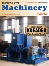
Knowledge On-The-Go <strong>Special</strong> <strong>Supplement</strong><br />
<strong>Machinery</strong><br />
http://rubbermachineryworld.com / http://tyremachineryworld.com<br />
<strong>World</strong><br />
EXTRUDERS
| Editor’s Note |<br />
<strong>Extruders</strong> And Extrusion<br />
<strong>Rubber</strong> extruders have a varied field of application.<br />
So, when you come across a rubber profile, strip,<br />
hose, cable, wire, cord coating, tire tread, v-belt,<br />
tube, or blank remember that they are only a few<br />
handful of products manufactured using extrusion<br />
process.<br />
<strong>Rubber</strong> industry only had Hot Feed <strong>Extruders</strong> until<br />
1950’s. Then came the Cold Feed <strong>Extruders</strong> and<br />
other variations as we see them today.<br />
Life today is mostly spent trying to catch up with<br />
latest developments. However, in the process the<br />
basics and fundamentals are sometimes overlooked.<br />
In this issue, we bring to you a ‘collector’s edition’<br />
on <strong>Extruders</strong> and Extrusion incorporating the<br />
fundamentals, that I hope will find space in your<br />
digital library.<br />
My sincere thanks to Dr. S. N. Chakravarty, President<br />
of Elastomer Technology Development Society, for<br />
his inputs with the material for this edition.<br />
As always, I welcome your feedback on<br />
rubbermachineryworld@gmail.com.<br />
<strong>Extruders</strong> and the<br />
process of Extrusion<br />
has different<br />
applications in the<br />
rubber and tyre<br />
industry.<br />
3<br />
Best Regards<br />
Prasanth Warrier<br />
rubbermachineri<br />
rubbermachineryworld<br />
+<strong>Rubber</strong>machineryworld1<br />
grp/home?gid=8252803<br />
(Disclaimer: All the pictures and statements in this special supplement are sourced <strong>from</strong> web or shared by respective companies.<br />
All copyrights belong to actual owner. <strong>Rubber</strong> <strong>Machinery</strong> <strong>World</strong> does not independently verify them nor will vouch for their<br />
genuineness, hence will not be liable for any misrepresented data. The images are used here for representation purpose only.)<br />
rubbermachineri<br />
<strong>Rubber</strong> & <strong>Tyre</strong> <strong>Machinery</strong> <strong>World</strong> | FEB 2016
| EXTRUDERS |<br />
4<br />
Image of A Strainer Extruder - Pelmar Engineering Ltd.<br />
<strong>Rubber</strong> & <strong>Tyre</strong> <strong>Machinery</strong> <strong>World</strong> | FEB 2016
| EXTRUDERS |<br />
Your <strong>Extruders</strong> And Its Extrusion<br />
Process<br />
Prasanth Warrier<br />
With Inputs of Dr. S.N. Chakravarty<br />
5<br />
<strong>Rubber</strong> extruders have a varied field of<br />
application. So, when you come across a<br />
rubber profile, strip, hose, cable, wire, cord<br />
coating, tire tread, v-belt, tube, or blank<br />
remember that they are only a few handful<br />
of products manufactured using extrusion<br />
process.<br />
Introduction<br />
<strong>Extruders</strong> are machines, which shape rubber<br />
to a profiled strip by forcing it through a die.<br />
In the simplest form an extruder consists of<br />
four basic components viz.<br />
<strong>Rubber</strong> & <strong>Tyre</strong> <strong>Machinery</strong> <strong>World</strong> | FEB 2016
| EXTRUDERS |<br />
Image of A Ram Extrusion Line - Barwell<br />
6<br />
(a) a device system<br />
(b) a barrel<br />
(c) a ram or screw for forcing the rubber<br />
through the barrel and<br />
(d) a head holding the die which ultimately<br />
gives the desired shape.<br />
Ram extruders are not<br />
frequently used and are good<br />
for very specialized extrusions.<br />
The fundamental distinction between two<br />
types of extruders is in their mode of<br />
operation:<br />
1. Continuous: Delivers rubber in a<br />
continuous manner and has a rotating<br />
member or screw; here the pressure is<br />
produced by a screw.<br />
2. Discontinuous: Delivers rubber in an<br />
intermittent fashion and has a<br />
reciprocating ram or screw. These type<br />
of extruders are ideally suited for batch<br />
type processes such as injection<br />
moulding.<br />
Screw Type And Ram Type <strong>Extruders</strong><br />
die is attached to cylinder and ram pushes<br />
the compound through the die to form a<br />
profiled section.<br />
Advantages:<br />
• Extrusion can be carried out at lower<br />
temperatures.<br />
• Difficult compounds can be extruded.<br />
• Easy to clean.<br />
• Useful to short runs.<br />
• Useful for compounds which need to be<br />
strained through gauge for quality<br />
products requiring completely<br />
contamination-free material.<br />
In Ram <strong>Extruders</strong>, a quantity of warm<br />
compound is placed into the cylinder, the<br />
Ram extruders are not frequently used and<br />
are good for very specialized extrusions.<br />
<strong>Rubber</strong> & <strong>Tyre</strong> <strong>Machinery</strong> <strong>World</strong> | FEB 2016
| EXTRUDERS |<br />
A Screw Extruder consists of five<br />
components viz.<br />
(a) Drive system<br />
(b) A feed hopper<br />
(c) A screw rotating within<br />
(d) A barrel<br />
(e) A head and die.<br />
The basic principle is that the screw carries<br />
material <strong>from</strong> the feed hopper by acting as a<br />
conveyor or a hump providing pressure to<br />
extrude or force the material along the<br />
machine barrel through the head and the<br />
die.<br />
The extruder drive system comprises of an<br />
AC or DC motor along with a reduction gear<br />
The basic principle is that the<br />
screw carries material <strong>from</strong> the<br />
feed hopper by acting as a<br />
conveyor.<br />
unit for power transmission. The extruder<br />
drive has to turn the screw at the desired<br />
speed. It should be able to maintain a<br />
constant screw speed because variations in<br />
screw speed will result in throughput<br />
fluctuation, which in turn will vary the<br />
dimensions of the extrudate.<br />
The purpose of the feed hopper is to receive<br />
material and pass it down to the flights of<br />
the screw. It is mostly supplied in the form<br />
of strip.<br />
8<br />
Image of A Screw Type Cold Feed Extruder - Pelmar Engineering Ltd.<br />
<strong>Rubber</strong> & <strong>Tyre</strong> <strong>Machinery</strong> <strong>World</strong> | FEB 2016
| EXTRUDERS |<br />
Extruder Screw<br />
The screw rotated within the Barrel, the<br />
usual clearance is approximately 0.40 mm.<br />
Normally, the barrel is fitted with a<br />
detachable liner in the form of a sleeve<br />
which is highly wear and corrosion resistant,<br />
made of hardened steel. The barrel is made<br />
double walled for steam or water circulation<br />
so that a constant temperature is maintained<br />
in the extruder head.<br />
A conventional extruder screw has three<br />
geometrically different sections.<br />
A conventional extruder screw<br />
has three geometrically<br />
different sections - Feed,<br />
Metering and Compression.<br />
compression section. In going <strong>from</strong> feed<br />
section towards the metering section, a<br />
compression of the material in the screw<br />
channel takes place, which is essential for<br />
the proper functioning of extruders. The<br />
compression streamlines flow, helps to<br />
eliminate air and also ensures a constant<br />
pressure in the head.<br />
9<br />
1. Feed section (closest to the feed opening)<br />
generally has deep flights and consists of<br />
approximately 1/5th of the length of the<br />
screw. The material in this section will<br />
mostly be in solid state.<br />
2. Metering section (closest to the die)<br />
usually has shallow flights and consists of<br />
approximately 2/5th of the length of the<br />
screw . The material in this section will<br />
mostly be in molten state.<br />
3. This section connects the feed section and<br />
the metering section, is called as<br />
Screws are made of steel alloy forging, heat<br />
treated to a machinable hardness and hard<br />
chrome plated. The flight lands are surface<br />
hardened to approximately 600 Brinnel.<br />
The screw is internally bored to facilitate<br />
water-cooling.<br />
The extrusion process has to be effective.<br />
What does this mean to you? Your extruded<br />
profile temperature must be within<br />
required limits to prevent scorching.<br />
<strong>Rubber</strong> & <strong>Tyre</strong> <strong>Machinery</strong> <strong>World</strong> | FEB 2016
| EXTRUDERS |<br />
The key screw design elements are Pitch,<br />
Flights and Core Diameter.<br />
Reputed manufacturers offer<br />
different screw designs.<br />
Flights: The built up part in between<br />
which the rubber compound traverses.<br />
Pitch: Distance between two consecutive<br />
flights<br />
Core Diameter: Diameter of the Core<br />
Shaft<br />
Each manufacture has their own design of<br />
screw. However, the basic function remain<br />
same. An adjustment can be made for<br />
volume occupied by the flight lands. Screw<br />
design has a direct bearing on out put and<br />
quality of Extrudate. Output rate depends<br />
upon the screw design and geometry of<br />
extrudate.<br />
In general, you could increase output by<br />
either or a combination of the following<br />
- Decrease the Flights<br />
- Increase the Pitch<br />
- Increase the Core Diameter<br />
Reputed manufacturers offer different<br />
screw designs to process your specific<br />
rubber compound requirements. One of the<br />
basic characteristics of all the extrusion<br />
process is the clearance between Barrel and<br />
screw. This is generally<br />
permitted to a limit in order to control<br />
• porosity<br />
• extrusion temperature<br />
10<br />
Schematic of a screw inside barrel and the different terms. Image <strong>from</strong> Web.<br />
Core Diameter<br />
<strong>Rubber</strong> & <strong>Tyre</strong> <strong>Machinery</strong> <strong>World</strong> | FEB 2016
| EXTRUDERS |<br />
Image: VMI<br />
12<br />
<strong>Extruders</strong> are usually designated by the<br />
diameter of the extruder barrel. The ratio<br />
of relative output of extruders varies as<br />
the square of the screw diameter . Thus<br />
the output of a 60 mm extruder will be 2.2<br />
times that of a 40 mm extruder.<br />
The extruder is operated in such a manner<br />
so that temperature is gradually more <strong>from</strong><br />
feed to discharge, the die being the hottest<br />
part.<br />
When you choose a extruder,<br />
you should discuss the design,<br />
material technology and<br />
manufacturing accuracy.<br />
The length of a rubber extruder depends on<br />
whether it is a hot feed or cold feed type.<br />
Hot feed extruders are usually very short<br />
about 3D to 5D while cold feed ones range<br />
<strong>from</strong> 12D to 24D.<br />
Hot Feed Extruder (HFE)<br />
When you choose a rubber extruder, you<br />
should deliberate and discuss extensively<br />
upon the design, material technology and<br />
manufacturing accuracy of screw, barrel<br />
and die-head.<br />
Very few manufacturers world-wide can<br />
guarantee you a well-designed and<br />
precisely manufactured rubber extruder.<br />
An additional designation often used is the<br />
length to diameter (L/D) ratio . This is an<br />
important factor in the selection of<br />
extruders to match process requirements.<br />
<strong>Rubber</strong> industry only had Hot Feed<br />
<strong>Extruders</strong> until 1950’s. HFE’s extrude your<br />
rubber compounds at reduced<br />
temperatures.<br />
The screw depth of a HFE is relatively<br />
larger and you get a consistent output due<br />
to its short screw design. L/D ratio is mostly<br />
in the range of 4:1 to 6:1 which keeps your<br />
rubber compound dwell time and its<br />
temperature increase to a minimum.<br />
In many cases the screw has increasing<br />
pitch.<br />
<strong>Rubber</strong> & <strong>Tyre</strong> <strong>Machinery</strong> <strong>World</strong> | FEB 2016
| EXTRUDERS |<br />
Each HFE has an hopper and feed roller<br />
section with spiral undercut liner that<br />
allows your compound to enter the<br />
extruder easily. The feed roller on a hot<br />
feed extruder allows your compound to<br />
pass the scraper knife, directed around the<br />
roll and then fed back into the hopper. The<br />
feed roll bearings are placed in positions to<br />
prevent contamination. You can vary the<br />
output by changing the screw speed using<br />
variable speed drives.<br />
In most cases, the screw has decreasing<br />
pitch. The screw has increasing root<br />
diameter with more flight depth at feed end<br />
which increase <strong>from</strong> feed to discharge. And<br />
of course, there are various other designs<br />
available.<br />
You can discuss with your manufacturer<br />
and avail various options of screws for a<br />
wide range of compound and extrusion<br />
applications.<br />
14<br />
Despite these advantages, the HFE’s are<br />
getting outdated in many applications.<br />
Because the rubber that is fed into a Hot<br />
Feed Extruder needs to be pre-heated or<br />
warmed using two-roll mills to achieve the<br />
required degree of viscosity and<br />
temperature that facilitates smooth flow of<br />
rubber, its compaction and extrusion<br />
through the die.<br />
And that made experts consider Cold Feed<br />
<strong>Extruders</strong>.<br />
Cold Feed Extruder (CFE)<br />
The output of an extruder is dependent on<br />
size of extruder i.e. the ratio of L/D.<br />
First estimate of out put is expressed as :<br />
Output = A (L/2) x R x d<br />
A = Cross sectional area of extruder<br />
L = Lead Length<br />
R = Revolution per minute<br />
d = density of rubber<br />
Generally these exists a liner relationship<br />
between RPM & output<br />
Cold Feed <strong>Extruders</strong> are designed and<br />
manufactured with specially designed<br />
screws best suited for cold feeding of<br />
rubber.<br />
While manufacturers offer L/D ratio up to<br />
24:1, the most preferred by end-users is<br />
generally in the range 12:1 to 18:1.<br />
For feeding the cold rubber, it is<br />
recommended that you use a feeding<br />
conveyor with metal detector to remove<br />
metal particles. This avoids damage to the<br />
screw or barrel. In some plants, the<br />
Image of Hot Feed & Cold Feed Extruder Screws<br />
<strong>Rubber</strong> & <strong>Tyre</strong> <strong>Machinery</strong> <strong>World</strong> | FEB 2016
| EXTRUDERS |<br />
15<br />
Image <strong>from</strong> Web: Feeding conveyor with Metal Detector<br />
For feeding the cold rubber, it is recommended that you use a<br />
feeding conveyor with metal detector to remove metal particles.<br />
Image <strong>from</strong> Web: A Set of Compact TCU’s<br />
below Cold Feed Extruder.<br />
sensitivity of the metal detector is<br />
found to be calibrated to a low value<br />
that it virtually renders the detector<br />
useless.<br />
Every CFE comes with a Temperature<br />
Controller Unit (TCU) that controls the<br />
barrel temperature so that the shape<br />
and size of the extruded products are<br />
uniform.<br />
<strong>Rubber</strong> & <strong>Tyre</strong> <strong>Machinery</strong> <strong>World</strong> | FEB 2016
| EXTRUDERS |<br />
The different Cold Feed <strong>Extruders</strong> (CFE)<br />
and their uses are:<br />
Plain Barrel Type Cold Feed Extruder:<br />
These CFE’s as the name suggests have a<br />
plain barrel and used in manufacturing of<br />
hoses, blanks, fluorocarbon rubber, butyl<br />
rubber, etc.<br />
Pin Barrel Type Cold Feed Extruder:<br />
These are equipped with metallic pins fixed<br />
along the circumference in full length of<br />
screw. These pins enhance the mixing and<br />
dispersion of your rubber as it is kneaded<br />
between the barrel and screw. And the<br />
The flexibility in Pin Type Cold<br />
Feed <strong>Extruders</strong> endears to all<br />
making it a ‘Universal Extruder’<br />
for many rubber formulations.<br />
result is processed rubber with outstanding<br />
homogeneity and extrudate quality. The<br />
number of pins may be optimised by<br />
process and if required pins <strong>from</strong> last zone<br />
i.e. towards head may be blocked. These<br />
pins are generally 8 to 10 in circumference.<br />
For example, in 10 rows you will have 8x10<br />
=80 pins protruding out of the barrel<br />
towards the screw center.<br />
16<br />
Image <strong>from</strong> Web: Pin Barrel Type Cold Feed Extruder<br />
<strong>Rubber</strong> & <strong>Tyre</strong> <strong>Machinery</strong> <strong>World</strong> | FEB 2016
| EXTRUDERS |<br />
18<br />
Image Of Quadruplex.<br />
Source: Canmade<br />
This flexibility in Pin Type Cold Feed<br />
<strong>Extruders</strong> endears to all making it a<br />
‘Universal extruder’ for many rubber<br />
compound formulations involving varied<br />
applications. Hard rubber compounds also<br />
can be processed because of high extruder<br />
torque.<br />
Vent Type Cold Feed Extruder<br />
Vent type or vacuum type extruders were<br />
developed for production of non-porous<br />
profiles and hoses. These CFE’s have a<br />
custom-built screw, and a degassing barrel<br />
with a vacuum pump attached to vent<br />
bubbles out of extruded compounds.<br />
Multiplex lines of piggy-back<br />
type have compact construction.<br />
Co-extrusion<br />
Customer-specific customization and usage<br />
complexity demands led to the introduction<br />
of co-extrusion for manufacturing of<br />
various profiles. And so you today have<br />
Simplex, Multiplex (Duplex, Triplex,<br />
Quadruplex, and Quintuplex) and Roller<br />
Head technology. Multiplex lines of piggyback<br />
type of 2,3,4, and 5 layers have a<br />
compact construction.<br />
<strong>Rubber</strong> & <strong>Tyre</strong> <strong>Machinery</strong> <strong>World</strong> | FEB 2016
| EXTRUDERS |<br />
20<br />
Roller-Head-Extruder<br />
Roller Head Technology involves a<br />
combination of extruder with preform head<br />
and two-roll calender. They offer twin<br />
advantages of – high uniformity of the<br />
material thickness over the entire sheet<br />
width with absence of air traps even at<br />
higher thicknesses (~20mm thick as against<br />
conventional calender lines that give max<br />
3mm thick sheets with or without air traps)<br />
and excellent homogeneity of the material<br />
produced.<br />
Both these characteristics are important for<br />
high-quality rubber products such as tire<br />
components, V-belts, conveyor belts, tank<br />
linings, cover sheets, blank sheets and<br />
roofing sheets. For even thickness across<br />
the entire sheet width of the roller head,<br />
there are three options that can be used<br />
alone or in combination with one another –<br />
roll crowning, roll crossing or roll bending,<br />
that will compensate for the elastic<br />
deflection of rolls.<br />
In today’s world you will see that usages of<br />
these technologies are overlapped. For<br />
example, in tire industry, you can notice<br />
that<br />
- Tread & Sidewall are extruded using<br />
Simplex, Duplex, Triplex, Quadruplex<br />
Lines<br />
- Apex are extruded using through Simple<br />
and Duplex.<br />
- Inner Liner are extruded using Simple,<br />
Duplex & Roller Head Technology.<br />
Image: KraussMafei Berstoff<br />
<strong>Rubber</strong> & <strong>Tyre</strong> <strong>Machinery</strong> <strong>World</strong> | FEB 2016
| EXTRUDERS |<br />
Image: Bharaj Make Cold Feed Extrusders equipped with Co-Extrusion Head<br />
21<br />
Extruder Head and Die Design<br />
The key to the extrusion is the extruder<br />
head that transforms the shape of the<br />
rubber while leaving the barrel to<br />
produce a dimensionally accurate and<br />
stable profile.<br />
The purpose of extruder Head is to<br />
equalise the pressure <strong>from</strong> the screw and<br />
barrel andto transport the compound<br />
smoothly at equal pressures and speed to<br />
the die.<br />
The purpose of Die is to give the compound<br />
the desired shape. The extrudates shrink<br />
along their length and increase in thickness<br />
and width, the behavior being termed ‘die<br />
swell’ which depends upon<br />
(i) rheological characteristics compound<br />
(ii) shape of head and extrudate<br />
(iii) pressure in the head<br />
(iv) the head and compound temperatures.<br />
Generally die making and die design<br />
depends on experience, however a good<br />
control on compound properties gives<br />
better extrusion.<br />
It is necessary to get a swelling factor at<br />
each point of profile for a particular<br />
compound. This varies <strong>from</strong> centre of die to<br />
extreme ends. Die swell is defined as ratio<br />
of extrudate section & cross section of die.<br />
<strong>Rubber</strong> & <strong>Tyre</strong> <strong>Machinery</strong> <strong>World</strong> | FEB 2016
| EXTRUDERS |<br />
24<br />
Source: CGEC<br />
This depends on Polymer, Carbon type and<br />
PHR, Viscosity, Lead angle (Bevel) of die etc.<br />
Some of the die heads include:<br />
1) Straight Head / Tube Head for hoses<br />
(circular or square) and technical profiles.<br />
2) Cross Heads for hoses and technical<br />
profiles <strong>from</strong> one, two or three different<br />
compounds.<br />
3) Single Tread Heads for rubber profiles.<br />
4) Multiple Tread Heads (Piggy-back) for<br />
rubber profiles.<br />
5) Slit Tube Heads for producing sheets<br />
inexpensively.<br />
Die swell depends on Polymer,<br />
Carbon type and PHR, Lead angle<br />
of die, etc.<br />
6) Preform Heads for sheets and rubber<br />
profiles.<br />
7) Strainer Heads to strain raw rubber,<br />
rubber compounds and reclaim rubber.<br />
8) Pelletizer Heads to process rubber<br />
materials ground into granules.<br />
9) Pork chop Heads to produce granulated<br />
raw rubber.<br />
<strong>Rubber</strong> & <strong>Tyre</strong> <strong>Machinery</strong> <strong>World</strong> | FEB 2016
| EXTRUDERS |<br />
Your main goal of extrusion is to get the highest output<br />
at good quality of product within the safe temperature<br />
limits of the products.<br />
Image: Triplex Extruder. Source: Troester<br />
25<br />
<strong>Rubber</strong> & <strong>Tyre</strong> <strong>Machinery</strong> <strong>World</strong> | FEB 2016
| EXTRUDERS |<br />
Gear Box<br />
A gearbox is the single-most-expensivecomponent<br />
on an extruder. Hence, you<br />
should be more cautious while selecting.<br />
First things first – Why do your single screw<br />
extruders need gearboxes?<br />
Extruder manufacturers prefer 1800/1500<br />
RPM or 1200/1000 RPM motors (depending<br />
on your country of use) because they are<br />
economical, readily available and compact<br />
in size to mount on your extruder base.<br />
However, most rubber extruder screws<br />
during production run in the speed range<br />
of 4 rpm to 40 rpm.<br />
Hence, the role of a gearbox or gear<br />
reducer here is to reduce the drive motor’s<br />
speed and, in turn, multiply the available<br />
torque <strong>from</strong> the motor in order to produce<br />
sufficient power to mix and push out your<br />
rubber compound.<br />
As an individual and independent<br />
component, the key specification that<br />
A gearbox is the single-mostexpensive<br />
component of an<br />
extruder. Hence, you should be<br />
more cautious while selecting.<br />
26<br />
Image: Wikov<br />
<strong>Rubber</strong> & <strong>Tyre</strong> <strong>Machinery</strong> <strong>World</strong> | FEB 2016
| EXTRUDERS |<br />
30<br />
defines the capacity and durability of your<br />
extruder gearbox is the power (HP/kW)<br />
rating along with its service factor (SF).<br />
Single screw extruder gearboxes are<br />
normally rated for power (HP/kW) or<br />
torque at a specific rpm based on common<br />
calculations and standards. This uniform<br />
standard allows you to compare gearboxes<br />
<strong>from</strong> different manufacturers.<br />
Your extruder manufacturers follow these<br />
guidelines and select a model for different<br />
service factors and applications. A key<br />
question you should ask is whether, the SF<br />
considered by your manufacturer is optimal<br />
for your extrusion application or not.<br />
Knowledge of AGMA (American Gear<br />
Manufacturers Association)<br />
recommendation will certainly help you to<br />
discuss better with extruder manufacturers,<br />
but experienced gearbox manufacturers<br />
can guide you even better. I have witnessed<br />
buyers in Asia been taken for a ride for their<br />
ignorance and offered lower specification<br />
gearboxes on their extruders to compete on<br />
cost.<br />
with a calculated rating of 367.5 kW would<br />
have a quoted rating of 210 kW with a 1.75<br />
service factor.<br />
The overall rating of a gearbox is based on<br />
the ratings of all its individual components.<br />
This includes the gear teeth design, gear<br />
hardness, shaft dimensions, bearing<br />
selection and sizes, housing design<br />
(thickness & rigidity), and thermal<br />
considerations. All these considerations are<br />
to ensure that your gearbox has sufficient<br />
support and capacity to effectively transmit<br />
the motor torque to the screw without<br />
significant distortion or failure.<br />
Within the gearbox, the most important<br />
component (and most expensive) is it’s<br />
thrust bearing. You evaluate a thrust<br />
bearing based on its type and life (B-10 or<br />
L-10 rating).<br />
The B-10 Life (sometimes called L-10 Life)<br />
of the thrust bearing is based on an<br />
engineering calculation that estimates the<br />
number of hours of operation at which 10<br />
per cent of the bearings are likely to fail.<br />
When you compare gearboxes, always<br />
evaluate on calculated power. The formula<br />
for calculated power of a gearbox is:<br />
Calculated Power = Quoted Power X<br />
Service Factor<br />
Typically, single screw rubber extruder<br />
gearbox has service factors of 1.5 or 1.75 for<br />
optimal operating capacity. For example, a<br />
6 inch pin type cold feed extruder gearbox<br />
Additional rating adjustment factors are to<br />
be applied to the basic B-10 life based on<br />
application factors including how the<br />
bearing is mounted.<br />
For example, a thrust bearing that is<br />
mounted between two radial bearings is<br />
more likely to have precise thrust bearing<br />
alignment, and will therefore have a higher<br />
rating adjustment factor.<br />
<strong>Rubber</strong> & <strong>Tyre</strong> <strong>Machinery</strong> <strong>World</strong> | FEB 2016
KELACHANDRA MACHINES<br />
(MFRS. OF RUBBER INDUSTRIAL MACHINERY)<br />
Chingavanam - 686 531, Kottayam, Kerala. India.<br />
Phone Off: +91- 481-2430325. Fax: +91- 481-2430596<br />
e-mail: km1912@gmail.com
| EXTRUDERS |<br />
Here are 6 other key criteria of a gearbox<br />
evaluation, which you should know<br />
1. Gear Design, Hardness and its<br />
Construction<br />
Each of the individual gears that go into<br />
your gearbox assembly are rated for power<br />
or torque based on their strength and<br />
durability ratings. The calculations would<br />
be according to industry standard AGMA<br />
rating systems. Factors include the gear<br />
tooth pitch, center distance, material and<br />
hardness.<br />
2. Gear Shafts<br />
The shafts must be designed to transmit the<br />
full power and torque capacity of the gears.<br />
The length and diameter of these shafts is<br />
decisive and must match the ability to<br />
transmit this torque without excessive<br />
deflection, fatigue and failure. The diameter<br />
of the input shaft must be adequate to<br />
properly support sheaves (in the case of belt<br />
driven models) or a coupling. The output<br />
shafts must be properly designed to handle<br />
the correct range of screw shanks that will<br />
be inserted. Adequate access to the drive<br />
keys is beneficial when they become worn<br />
or damaged and need to be replaced.<br />
3. Radial Bearings and Seals<br />
The radial bearings support the rotational<br />
forces of the gear shafts and must be<br />
designed to handle the load forces and<br />
speeds effectively. The dynamic load<br />
capacity of these radial bearings must also<br />
be considered when evaluating the design<br />
and durability of the gearbox. Radial<br />
bearings must also be properly lubricated<br />
and sealed.<br />
4. Gearbox Housing Design - Construction<br />
Cast Iron is the cost-effective material of<br />
choice for most manufacturers.<br />
Traditionally, CI gearboxes are made in two<br />
pieces, split either horizontally or vertically.<br />
Newer designs have the gearbox housing<br />
cast as one piece to reduce any potential<br />
leakages.<br />
5. Thrust Bearing<br />
Thrust bearing isolates the backward forces<br />
<strong>from</strong> the screw. The larger the screw and/or<br />
the higher the back pressure, the greater<br />
the backward thrust forces. There are three<br />
basic types of thrust bearings – cylindrical,<br />
spherical and tapered.<br />
6. Serviceability<br />
When you select a gearbox, you should give<br />
prime importance to the availability to<br />
affordable parts and service. It is best to<br />
select rubber extruder suppliers who<br />
purchase their gearboxes <strong>from</strong> proven and<br />
reputable manufacturers that specialize<br />
only in gearboxes for better serviceability.<br />
An old gearbox manufactured around<br />
through-hardened process and shaved gears<br />
technology has shafts, bearings and<br />
housings designed accordingly. Replacing<br />
new hardened gears with a higher HP<br />
capacity, does not automatically guarantee<br />
the gearbox rating to increase, if you do not<br />
replace the assembly with stronger shafts,<br />
bearings and housing.<br />
Gear manufacturing technology today has<br />
33<br />
<strong>Rubber</strong> & <strong>Tyre</strong> <strong>Machinery</strong> <strong>World</strong> | FEB 2016
| EXTRUDERS |<br />
Image of Extrusion Line. Source: CGEC<br />
changed and consists of carburized and<br />
ground gears. These gears are capable of<br />
delivering much more power in its smaller<br />
size. When old gear designs are<br />
constructed using the new materials and<br />
process, the power calculations yield much<br />
higher gear tooth ratings. But if the rest of<br />
the design is unchanged, and the same<br />
bearings, shafts, and housings are used, the<br />
total gearbox rating cannot simply be based<br />
on the new higher gear rating alone.<br />
The higher torque could never be applied to<br />
the original sized input shaft without<br />
causing bending or twisting. The bearings<br />
and/or shafts would be overloaded with the<br />
higher forces, and the housing would<br />
probably not have sufficient strength to<br />
resist significant distortion. Reputed<br />
gearbox rebuilders will guide you well.<br />
Automation<br />
The different levels of automation of downstream<br />
line for extruders makes the<br />
extrusion operations highly user-friendly<br />
and efficient.<br />
In the case of extruder heads, there are<br />
different options depending on user<br />
requirement - a simple, single-compound<br />
single-component mechanically opening<br />
extruder head to a sophisticated costeffective<br />
PLC controlled hydraulically<br />
opening multi-compound multi-cavity head.<br />
So, rubber extrusion is in itself a vast and<br />
interesting subject.<br />
RMW<br />
35<br />
<strong>Rubber</strong> & <strong>Tyre</strong> <strong>Machinery</strong> <strong>World</strong> | FEB 2016
AMCL MACHINERY LIMITED<br />
SERVICE TO THE NATION FOR FOUR DECADES<br />
Product Range<br />
• <strong>Rubber</strong> Mixer – 76" liter and 270 liter.<br />
• Mixing Mills – 16", 22", 26" and special sizes<br />
• Hot feed extruders – 6" and 8"<br />
• <strong>Rubber</strong> Calenders – 2/3 rolls.<br />
• Bias <strong>Tyre</strong> Building machine – RB1/RB3<br />
• Automatic LCV <strong>Tyre</strong> Building Machine – RB1619<br />
• Automatic Truck <strong>Tyre</strong> Building Machine-RB2022<br />
• Mechanical <strong>Tyre</strong> Curing Presses – Scooter to Truck size<br />
• Bladder Curing Presses<br />
• Tube Splicers<br />
For all your enquiries please contact:<br />
AMCL MACHINERY LIMITED<br />
Works: Plot No.A1/1, MIDC, Butirobi-441122, Nagpur<br />
Mumbai office: 202, Ackruti Centre Point, MIDC Central Road, Andheri (East), Mumbai-400 093.<br />
Contact person: Mr. S.H. Mehta<br />
Mobile No. +91-9004697430. Email: shmehta@amcl.in Website: www.amcl.in
KELACHANDRA MACHINES<br />
(MFRS. OF RUBBER INDUSTRIAL MACHINERY)<br />
Chingavanam - 686 531, Kottayam, Kerala. India.<br />
Phone Off: +91- 481-2430325. Fax: +91- 481-2430596<br />
e-mail: km1912@gmail.com