Deliverables and Services - IHP Microelectronics
Deliverables and Services - IHP Microelectronics
Deliverables and Services - IHP Microelectronics

Create successful ePaper yourself
Turn your PDF publications into a flip-book with our unique Google optimized e-Paper software.
tungen ist es notwendig, auch alle parasitären Kapazitäten<br />
und Widerstände der Metallverbindungen zu<br />
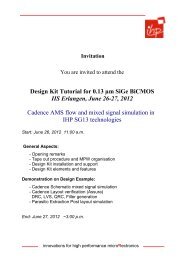
minimieren. In Abb. 20 sind Gatterverzögerungszeiten<br />
für zwei Ringoszillatorlayouts, die sich durch die parasitären<br />
Beiträge der Metallverbindungen unterscheiden,<br />
gezeigt. Die erreichte Rekordverzögerungszeit von 3,0 ps<br />
basiert neben der hohen Transistorgeschwindigkeit auf<br />
der Minimierung der parasitären Beiträge der Metallverbindungen<br />
auf dem Chip.<br />
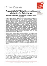
Abb. 18: Transmissionselektronische Aufnahme eines HBTs mit<br />
einer Emitterweite von 0,17 µm.<br />
Fig. 18: transmission electron micrograph of an HBt with an<br />
emitter width of 0.17 µm.<br />
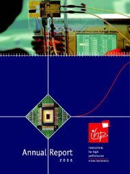
Abb. 19: Maximale Transitfrequenz f T und maximale Oszillationsfrequenz<br />
f max von HBTs mit Emitterweiten von 0,17 µm<br />
als Funktion der Emitterlänge.<br />
Fig. 19: peak transit frequency f t <strong>and</strong> maximum oscillation<br />
frequency f max of HBts with 0.17 µm emitter width<br />
as a function of emitter length.<br />
0 A n n u A l R e p o R t 2 0 0 7<br />
A U S G E w ä H L T E P R O J E K T E – S E L E C T E d P R O J E C T S<br />
CMl ring oscillators for two circuit layouts differing<br />
in the parasitic capacitances <strong>and</strong> resistances of the<br />
metal interconnects. the demonstrated record gate<br />
delay of 3.0 ps is based on the high transistor speed<br />
as well as on the minimization of the parasitics of the<br />
metal interconnects.<br />
Abb. 20: Gatterverzögerungszeiten von CML-Ringoszillatoren als<br />
Funktion des Stromes pro Gatter. Zwei Schaltungen mit<br />
verschiedenen parasitären Beiträgen der Verdrahtungsebenen<br />
sind verglichen.<br />
Fig. 20: Gate delays vs. current per gate for CMl ring oscillators.<br />
two designs with different interconnect parasitics are<br />
compared.