Deliverables and Services - IHP Microelectronics
Deliverables and Services - IHP Microelectronics
Deliverables and Services - IHP Microelectronics

You also want an ePaper? Increase the reach of your titles
YUMPU automatically turns print PDFs into web optimized ePapers that Google loves.
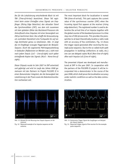
Abb. 12: Beispiel für die Messung einer Impuls-Sequenz an der<br />
Antenne.<br />
Fig. 12: Measured example of an impulse sequence at the<br />
antenna.<br />
2 A n n u A l R e p o R t 2 0 0 7<br />
A U S G E w ä H L T E P R O J E K T E – S E L E C T E d P R O J E C T S<br />
Der für die Lokalisierung entscheidende Block ist mit<br />
TOA (Time-of-Arrival) bezeichnet. Dieser Teil registriert<br />
beim ersten Eintreffen eines Signals am Empfänger<br />
(Rising Edge Detection) den aktuellen St<strong>and</strong><br />
des Synchronzählers (CNT), aus dem sich zusammen<br />
mit dem globalen Zähler des Basisb<strong>and</strong>-Prozessors die<br />
Ankunftszeit eines Impulses mit einer Genauigkeit von<br />
260 ps bestimmen lässt. Das schafft die Voraussetzung,<br />
um zumindest theoretisch eine Funkquelle bis auf wenige<br />
Zentimeter genau zu lokalisieren. Abb. 13 zeigt<br />
das im Empfänger erzeugte Triggersignal der Beispiel-<br />
Sequenz. Durch die sogenannte Mehrwegeausbreitung<br />
in Gebäuden (Reflexionen an Wänden usw.) sieht man<br />
nach jedem Impuls (LoS – Line-of-sight) auch später<br />
eintreffende Kopien des Signals (NLoS – None-line-ofsight).<br />
Dieser Chipsatz wurde im Jahr 2007 im <strong>IHP</strong> entwickelt<br />
und gefertigt und wird im Laufe des Jahres 2008 gemeinsam<br />
mit den Partnern im Projekt PULSERS II in<br />
einen Demonstrator integriert, der die Genauigkeit der<br />
Lokalisierung in der Praxis sowie die Datenkommunikation<br />
nachweisen soll.<br />
the most important block for localization is named<br />
toA (time-of-arrival). this part captures the current<br />
value of the synchronous counter (Cnt) when the<br />
incoming signal first appears at the receiver (rising<br />
edge detection). the registered number is used to determine<br />
the arrival time of an impulse together with<br />
the global counter of the baseb<strong>and</strong> processor in a time<br />
step size of 260 picoseconds. this provides the prerequisites<br />
to at least theoretically localize a radio node<br />
with an accuracy of few centimeters. Fig. 13 shows<br />
the trigger signal generated after receiving the example<br />
pulse sequence. Due to the so-called multi-path<br />
propagation in buildings (reflections at walls, etc.)<br />
one can see delayed copies nloS (non-line-of-sight)<br />
after each impulse loS (line-of-sight).<br />
the presented chipset was developed <strong>and</strong> manufactured<br />
at IHp in the year 2007. In cooperation with<br />
the partners of the pulSeRS II project it will be incorporated<br />
into a demonstrator in the course of the<br />
year 2008, which shall prove the localization accuracy<br />
under realistic conditions as well as the data communication.<br />
Abb. 13: Gemessenes Trigger-Signal des Empfängers am Beispiel<br />
der Impuls-Sequenz.<br />
Fig. 13: Measured trigger signal of the receiver for the example<br />
pulse sequence.