Deliverables and Services - IHP Microelectronics
Deliverables and Services - IHP Microelectronics
Deliverables and Services - IHP Microelectronics

Create successful ePaper yourself
Turn your PDF publications into a flip-book with our unique Google optimized e-Paper software.
A U S G E w ä H L T E P R O J E K T E – S E L E C T E d P R O J E C T S<br />
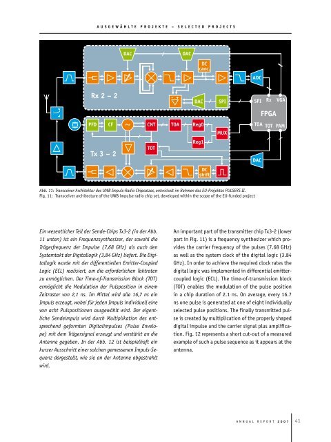
Abb. 11: Transceiver-Architektur des UWB Impuls-Radio Chipsatzes, entwickelt im Rahmen des EU-Projektes PULSERS II.<br />
Fig. 11: transceiver architecture of the uWB impulse radio chip set, developed within the scope of the eu-funded project<br />
Ein wesentlicher Teil der Sende-Chips Tx3-2 (in der Abb.<br />
11 unten) ist ein Frequenzsynthesizer, der sowohl die<br />
Trägerfrequenz der Impulse (7,68 GHz) als auch den<br />
Systemtakt der Digitallogik (3,84 GHz) liefert. Die Digitallogik<br />
wurde mit der differentiellen Emitter-Coupled<br />
Logic (ECL) realisiert, um die erforderlichen Taktraten<br />
zu ermöglichen. Der Time-of-Transmission Block (TOT)<br />
ermöglicht die Modulation der Pulsposition in einem<br />
Zeitraster von 2,1 ns. Im Mittel wird alle 16,7 ns ein<br />
Impuls erzeugt, wobei für jeden Impuls individuell eine<br />
von acht Pulspositionen ausgewählt wird. Der eigentliche<br />
Sendeimpuls wird durch Multiplikation des entsprechend<br />
geformten Digitalimpulses (Pulse Envelope)<br />
mit dem Trägersignal erzeugt und verstärkt an die<br />
Antenne gegeben. In der Abb. 12 ist beispielhaft ein<br />
kurzer Ausschnitt einer solchen gemessenen Impuls-Sequenz<br />
dargestellt, wie sie an der Antenne abgestrahlt<br />
wird.<br />
An important part of the transmitter chip tx3-2 (lower<br />
part in Fig. 11) is a frequency synthesizer which provides<br />
the carrier frequency of the pulses (7.68 GHz)<br />
as well as the system clock of the digital logic (3.84<br />
GHz). In order to achieve the required clock rates the<br />
digital logic was implemented in differential emittercoupled<br />
logic (eCl). the time-of-transmission block<br />
(tot) enables the modulation of the pulse position<br />
in a chip duration of 2.1 ns. on average, every 16.7<br />
ns one pulse is generated at one of eight individually<br />
selected pulse positions. the finally transmitted pulse<br />
is created by multiplication of the properly shaped<br />
digital impulse <strong>and</strong> the carrier signal plus amplification.<br />
Fig. 12 represents a short cut-out of a measured<br />
example of such a pulse sequence as it appears at the<br />
antenna.<br />
A n n u A l R e p o R t 2 0 0 7