Deliverables and Services - IHP Microelectronics
Deliverables and Services - IHP Microelectronics
Deliverables and Services - IHP Microelectronics

You also want an ePaper? Increase the reach of your titles
YUMPU automatically turns print PDFs into web optimized ePapers that Google loves.
A u S G e w ä H L t e p r o J e K t e – S e L e C t e d p r o J e C t S<br />
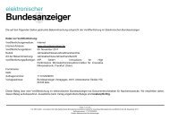
Der Kern des Chips ist ein VCO mit vier digitalen und zwei<br />
analogen Steuereingängen, der in Abb. 12 dargestellt<br />
ist. Über die vier digitalen Steuereingänge wird der<br />
gesamte Abstimmbereich von 4 GHz in 16 stark überlappende<br />
Frequenzbänder unterteilt, von denen jedes<br />
breiter als 1 GHz ist. Infolgedessen ist der Synthesizer<br />
robust bezüglich Temperaturänderungen und Alterung.<br />
Das geringe Phasenrauschen wurde durch die Verwendung<br />
zweier paralleler Regelkreise zur Fein- und Grobabstimmung<br />
des VCO erreicht. Um Strahlungsfestigkeit<br />
zu erzielen, wurden SiGe-HBTs für kritische Blöcke wie<br />
VCO und Frequenzteiler benutzt. Des Weiteren wurden<br />
die CMOS-Register dreifach ausgeführt, und es wird nach<br />
jeder Taktperiode eine Mehrheitsentscheidung an deren<br />
Ausgängen getroffen (Dreifach-Modus-Redundanz).<br />
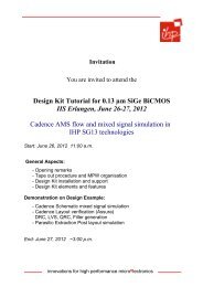
Abb. 13 zeigt ein typisches Phasenrauschspektrum im<br />
fractional-N Modus für drei verschiedene Ausgangsfrequenzen<br />
innerhalb eines Frequenzb<strong>and</strong>es. Infolge<br />
unserer neuartigen PLL-Architektur ist das Spektrum<br />
relativ unabhängig von der Ausgangsfrequenz. Design-<br />
Details und Messergebnisse wurden zusammengefasst<br />
in einer gemeinsamen Publikation von <strong>IHP</strong>, IMST, Kayser-Threde<br />
und Humboldt-Universität Berlin in Analog<br />
Integrated Circuits <strong>and</strong> Signal Processing, Springer-Verlag<br />
(im Druck).<br />
Abb. 12: Schematische Darstellung des spannungsgesteuerten<br />
Oszillators.<br />
Fig. 12: Schematic view of voltage-controlled oscillator.<br />
the core of the chip is a VCo array with four digital<br />
<strong>and</strong> two analog control inputs shown in Fig. 12. By<br />
using the four digital inputs, the total tuning range<br />
of 4 GHz is sub-divided into 16 strongly overlapping<br />
b<strong>and</strong>s, each having more than 1 GHz b<strong>and</strong>width. As a<br />
result, the synthesizer is robust with respect to temperature<br />
variations <strong>and</strong> aging. the low phase noise<br />
is achieved by using two parallel loops for fine <strong>and</strong><br />
coarse tuning of the VCo. In order to achieve radiation<br />
hardness, SiGe bipolar HBts were used for critical<br />
blocks such as VCo <strong>and</strong> frequency dividers. Moreover,<br />
the CMoS registers were tripled <strong>and</strong> a majority decision<br />
is performed at their outputs after every clock<br />
period (triple mode redundancy).<br />
Fig. 13 shows a typical phase noise spectrum in fractional-n<br />
mode at three different output frequencies<br />
within one frequency b<strong>and</strong>. Due to our novel pll<br />
architecture, the spectrum is relatively independent<br />
of the output frequency. Design details <strong>and</strong> measurement<br />
results have been summarized in a joint publication<br />
of IHp, IMSt, Kayser-threde <strong>and</strong> Humboldt<br />
university Berlin in Analog Integrated Circuits <strong>and</strong><br />
Signal processing, Springer (in press).<br />
Abb. 13: Gemessene Phasenrauschspektren innerhalb eines<br />
Frequenzb<strong>and</strong>es.<br />
Fig.13: Measured phase noise spectra within one frequency<br />
b<strong>and</strong>.<br />
A n n u A l R e p o R t 2 0 0 9