

STREETSCAPE GUIDANCE
streetscape-guidance
streetscape-guidance

You also want an ePaper? Increase the reach of your titles
YUMPU automatically turns print PDFs into web optimized ePapers that Google loves.
HOME<br />
INTRODUCTION<br />
PART A<br />
A vision for London’s streets<br />
PART B<br />
From strategy to delivery<br />
PART C<br />
New measures for new challenges<br />
PART D<br />
Balancing priorities<br />
PART F<br />
Appendix<br />
PART E<br />
Physical design and materials<br />
SECTION 6<br />
Introduction<br />
SECTION 7<br />
High quality footways<br />
SECTION 8<br />
Carriageways<br />
SECTION 9<br />
Crossings<br />
SECTION 10<br />
Kerbside activity<br />
SECTION 11<br />
Footway amenities<br />
SECTION 12<br />
Safety and functionality<br />
SECTION 13<br />
Street environment<br />
SECTION 14<br />
Transport interchanges<br />
Streetscape Guidance<br />
[Part E – Physical design and materials] Street environment 284<br />
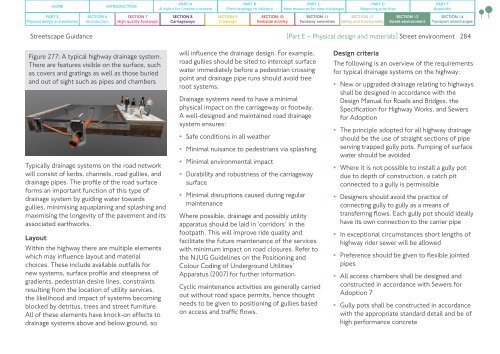
Figure 277: A typical highway drainage system.<br />
There are features visible on the surface, such<br />
as covers and gratings as well as those buried<br />
and out of sight such as pipes and chambers<br />
Typically drainage systems on the road network<br />
will consist of kerbs, channels, road gullies, and<br />
drainage pipes. The profile of the road surface<br />
forms an important function of this type of<br />
drainage system by guiding water towards<br />
gullies, minimising aquaplaning and splashing and<br />
maximising the longevity of the pavement and its<br />
associated earthworks.<br />
Layout<br />
Within the highway there are multiple elements<br />
which may influence layout and material<br />
choices. These include available outfalls for<br />
new systems, surface profile and steepness of<br />
gradients, pedestrian desire lines, constraints<br />
resulting from the location of utility services,<br />
the likelihood and impact of systems becoming<br />
blocked by detritus, trees and street furniture.<br />
All of these elements have knock-on effects to<br />
drainage systems above and below ground, so<br />
will influence the drainage design. For example,<br />
road gullies should be sited to intercept surface<br />
water immediately before a pedestrian crossing<br />
point and drainage pipe runs should avoid tree<br />
root systems.<br />
Drainage systems need to have a minimal<br />
physical impact on the carriageway or footway.<br />
A well-designed and maintained road drainage<br />
system ensures:<br />
• Safe conditions in all weather<br />
• Minimal nuisance to pedestrians via splashing<br />
• Minimal environmental impact<br />
• Durability and robustness of the carriageway<br />
surface<br />
• Minimal disruptions caused during regular<br />
maintenance<br />
Where possible, drainage and possibly utility<br />
apparatus should be laid in ‘corridors’ in the<br />
footpath. This will improve ride quality and<br />
facilitate the future maintenance of the services<br />
with minimum impact on road closures. Refer to<br />
the NJUG Guidelines on the Positioning and<br />
Colour Coding of Underground Utilities’<br />
Apparatus (2007) for further information.<br />
Cyclic maintenance activities are generally carried<br />
out without road space permits, hence thought<br />
needs to be given to positioning of gullies based<br />
on access and traffic flows.<br />
Design criteria<br />
The following is an overview of the requirements<br />
for typical drainage systems on the highway:<br />
• New or upgraded drainage relating to highways<br />
shall be designed in accordance with the<br />
Design Manual for Roads and Bridges, the<br />
Specification for Highway Works, and Sewers<br />
for Adoption<br />
• The principle adopted for all highway drainage<br />
should be the use of straight sections of pipe<br />
serving trapped gully pots. Pumping of surface<br />
water should be avoided<br />
• Where it is not possible to install a gully pot<br />
due to depth of construction, a catch pit<br />
connected to a gully is permissible<br />
• Designers should avoid the practice of<br />
connecting gully to gully as a means of<br />
transferring flows. Each gully pot should ideally<br />
have its own connection to the carrier pipe<br />
• In exceptional circumstances short lengths of<br />
highway rider sewer will be allowed<br />
• Preference should be given to flexible jointed<br />
pipes<br />
• All access chambers shall be designed and<br />
constructed in accordance with Sewers for<br />
Adoption 7<br />
• Gully pots shall be constructed in accordance<br />
with the appropriate standard detail and be of<br />
high performance concrete