Programing Tasks Part 1 Handdryer
Programing Tasks Part 1 Handdryer
Programing Tasks Part 1 Handdryer

You also want an ePaper? Increase the reach of your titles
YUMPU automatically turns print PDFs into web optimized ePapers that Google loves.
ROBO S T A R T E R A C T I V I T Y B O O K L E T<br />
fischertechnik Computing p. 16<br />
Before you get started p. 16<br />
Assembly p. 16<br />
Important Components p. 16<br />
Interface and Software p. 18<br />
Your first programming steps p. 18<br />
Programming <strong>Tasks</strong> <strong>Part</strong> 1 p. 19<br />
<strong>Handdryer</strong> p. 19<br />
Traffic Light p. 20<br />
Sliding Door p. 21<br />
<strong>Programing</strong> <strong>Tasks</strong> <strong>Part</strong> 2 p. 23<br />
Temperature Control p. 23<br />
Stamping Press p. 24<br />
Car Park Barrier p. 25<br />
Welding Robot p. 26<br />
What else can you do? p. 27<br />
15<br />
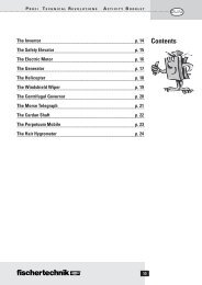
Contents<br />
GB+USA
GB+USA<br />
fischertechnik<br />
Computing<br />
Before you get<br />
started<br />
Assembly<br />
Important Components<br />
Before you get started 16<br />
ROBO S T A R T E R A C T I V I T Y B O O K L E T<br />
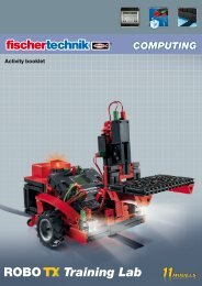
■ Welcome to our "computing world." We at fischertechnik use the term<br />
"computing" to mean the programing and control of models using the PC.<br />
The ROBO Starter Set is the optimal entry into this subject. Using the<br />
assembly instructions, you can build eight different models in a short time<br />
and these models range from a handdryer to a bar barrier for entry into<br />
parking garages on to a welding robot. Using an interface such as the<br />
ROBO I/O-Extension, you can connect the models with the PC. (Note!<br />
You can also use the ROBO interface, item No. 93293.) Then, you program<br />
the models quickly and simply with the graphic programing software, ROBO Pro.<br />
The following introduction is intended to help you to quickly find your way around in the computing<br />
world. Initially, this shows you how you should start and what you must do step by step. In addition, here<br />
you find programing tasks for all models in the building set. Of course, there are tips here for these tasks<br />
as well. You are given an exact description as to how you can program the models with the ROBO Pro<br />
software. As you will see, this is really great fun. So, let's go.<br />
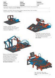
■ What do you really find in the building set?<br />
First, you will find several fischertechnik building blocks, a motor, lights and sensors as well as colored<br />
construction instructions for the building of<br />
eight different models. Let's look at this first.<br />
When you have unpacked all of the building blocks, you have to assemble some components first such<br />
as cables and plugs before you can really get started. The exact ones are described in the construction<br />
instructions in the paragraph "Assembly Help and Instructions." It is best to do this first.<br />
Motor<br />
This motor drives the fischertechnik models. The motor is operated with a voltage<br />
of 9 volts (direct current). The maximum output is about 1.1 watt with a<br />
speed of 7000 revolutions per minute (RPM).<br />
Gear unit<br />
A gear unit is attached to the motor and this unit reduces the RPM.<br />
The reduction is, including the motor worm gear and the toothed gear with the output shaft 64.8 : 1.<br />
The building set contains two different lights:<br />
Domed Light<br />
This is a normal light bulb for a voltage of 9V and a power consumption of about 0.1 ampere (A).
ROBO S T A R T E R A C T I V I T Y B O O K L E T<br />
Lens Tip Bulb<br />
A lens is a part of this light bulb and this focuses the light. It looks very much like the domed light so<br />
that you have to watch out and don't mistake these. To make it easier to see the difference, the plug<br />
base for this bulb is gray, but the domed light has a white plug base. You need the lens tip bulb to build<br />
a light barrier. Technical data: 9V , 0.15A<br />
Phototransistor<br />
You can also call the phototransistor a "brightness sensor." This is a "detector" that reacts to brightness.<br />
For a light barrier this is the counterpart to the lens tip bulb. When there is a high degree of brightness,<br />
that is when the transistor receives light from the lens tip bulb, it conducts electricity. If the light beam<br />
is interrupted, the transistor does not conduct any electricity.<br />
Caution: When connecting the phototransistor to the power supply, you must pay special attention to<br />
the right pole: red = plus.<br />
Sensing Device<br />
The sensing device is also called a touch sensor. When you press the red button, this moves a switch<br />
mechanically and electricity flows between the contacts 1 (center contact) and 3. At the same, the<br />
contact between the connections 1 and 2 is interrupted. So you can use the sensing device in two<br />
different ways:<br />
As a "closer"<br />
Contacts 1 and 3 are connected.<br />
When the button is pressed electricity flows.<br />
When the button is not pressed, no electricity flows.<br />
As a "opener"<br />
Contacts 1 and 2 are connected.<br />
When the button is pressed no electricity flows.<br />
When the button is not pressed, electricity flows.<br />
NTC Resistor<br />
This component is a heat sensor that you can use to measure<br />
temperatures. At 20°C, the resistance is 1.5kΩ (kilo ohms). NTC<br />
stands for Negative Temperature Coefficient. This simply means that<br />
the resistance value decreases when the temperature increases.<br />
The information, which the sensors supply to us such as bright-dark, pressed-not pressed, and<br />
temperature value, can be, as you will see later, passed to the PC through the interface and then with<br />
the help of the software, for example, you can program a motor to open a door as soon as the light<br />
barrier is interrupted.<br />
3<br />
2<br />
1<br />
17<br />
GB+USA<br />
Before you get started
GB+USA<br />
Interface and Software<br />
Before you get started 18<br />
ROBO S T A R T E R A C T I V I T Y B O O K L E T<br />
Your first<br />
programming steps<br />
■ Before you start to build models and create programs, you must install the ROBO Pro control software<br />
on your PC and then connect the interface, ROBO I/O extension, to your computer through the USB<br />
interface.<br />
How to do this is described in detail in the ROBO Pro handbook in chapters 1 and 2. Follow these<br />
instructions exactly now and you should not have any trouble to get the software and the ROBO I/O-<br />
Extension to run. When the ROBO I/O extension is connected to the PC for the first time, then the<br />
associated USB driver must be installed. This works just like for the ROBO interface and is described in<br />
the handbook for the ROBO Pro software in chapter 1.2.<br />
For the ROBO I/O-Extension you need a fischertechnik power supply with a voltage of 9V and a<br />
current of 1000mA such as the Energy Set or the Accu Set. Now, we wish you a lot of success with the<br />
installation and the connection of the software and the interface. After this, we will continue here.<br />
■ Now that the hardware and software are working, you can finally start with<br />
the programing. For this, we also need to use the ROBO Pro<br />
handbook again. There is no better way to start<br />
with programing than is described there<br />
in chapters 3 and 4. That's why we<br />
go back to this at this point. Work<br />
through both of these chapters carefully.<br />
To test the first control program, which you have developed there, you can use the "motor control" model<br />
from the Computing Starter building set.<br />
Build this model using the construction instructions and test your first program with this.
ROBO S T A R T E R A C T I V I T Y B O O K L E T<br />
■ After you have read through chapters 3 and 4 of the ROBO Pro handbook, you can now program some<br />
models from the Computing Starter building set. So, that's why we want to start right away. Every time<br />
when you have finished building a model and attached the wiring, you need to conduct a check using the<br />
interface test to determine if all outputs and inputs are correctly connected<br />
to the interface and the sensors, motors and lights are working properly.<br />
■ In your school in the bathroom,<br />
new handdryers were installed<br />
beside the wash basins. These have a<br />
light barrier, which allows you to turn on and<br />
turn off the blower. First, build the model as described in<br />
the construction instructions.<br />
Task 1:<br />
The handdryer is to be programed so that as soon as the light barrier is interrupted, the<br />
blower is to be turned on and then after five seconds it is to be turned off.<br />
<strong>Programing</strong> Tips:<br />
• First, in the program sequence, turn on the light for the light barrier at output M2. After this, wait a<br />
second so that the phototransistor has time to react to the light. Only then will the light barrier work<br />
properly.<br />
• Then you interrogate the phototransistor on input I1. If the value is 1 (light barrier not interrupted) then<br />
the input is to be interrogated continuously in a loop.<br />
• As soon as the value changes to 0 (light barrier interrupted), turn on the motor, M1, and then turn it<br />
off after five seconds.<br />
• Following this, the phototransistor is to be interrogated again and so forth.<br />
Start your program with the start button and check to see if it is working as desired. If it does work right,<br />
then you're on the right path to become a professional ROBO Pro programer.<br />
If it doesn't work, try to find out why:<br />
• With the interface test, you can check to see if all inputs and outputs are working and correctly connected.<br />
• While the program is running, you can follow the program flow with the red building blocks. This<br />
allows you to quickly see where an error has crept in.<br />
• Finally, you can compare your program with the complete sample program, <strong>Handdryer</strong> 1.rpp, which is<br />
found in the directory C:\Programs\ROBO Pro\SamplePrograms\ROBO Starter or<br />
C:\Programs\ROBO Pro\SamplePrograms\Computing Starter.<br />
Now that you have taken this hurdle, we want to change the task a bit.<br />
19<br />
<strong>Programing</strong> <strong>Tasks</strong><br />
<strong>Part</strong> 1<br />
<strong>Handdryer</strong><br />
<strong>Part</strong> 1<br />
GB+USA
GB+USA<br />
Traffic Light<br />
ROBO S T A R T E R A C T I V I T Y B O O K L E T<br />
<strong>Part</strong> 1<br />
20<br />
Task 2:<br />
The school principal, who is always interested in saving energy, doesn't like it when<br />
the handdryer continues to run for a time even if your hands are already dry. He asks<br />
you to design the program so that the blower is shutoff as soon as your hands are<br />
pulled back. That's not a problem for you, or?<br />
<strong>Programing</strong> Tips:<br />
• As in the first program, you interrogate the phototransistor I1 with a branch. If the value is 0, then turn<br />
the motor, M1, on and when the value is 1 then turn the motor, M1, off and so forth.<br />
• For this task, there is also a complete program, <strong>Handdryer</strong> 2.rpp, in case it is<br />
needed.<br />
■ A traffic light was put up in front of your house. Since the installer from<br />
the stop light company was under a lot of time pressure, you<br />
offer to do the programing for the control of the<br />
stop light for him. The man explains to you<br />
how the control is supposed to work. But first,<br />
build the model.<br />
Task 1:<br />
● Normally, the traffic light is to be green.<br />
● If the button I1 is pressed by a pedestrian then the traffic light is to change to yellow<br />
three seconds later and after an additional four seconds to red.<br />
● The red phase is to last 10 seconds followed by the red-yellow phase for three<br />
seconds.<br />
● Then it is to go back to green.<br />
<strong>Programing</strong> Tips:<br />
• The various indicator lights belong to the following interface outputs:<br />
Red: M1<br />
Yellow: M2<br />
Green: M3<br />
• Turn the lights on and off one after the other so that the desired sequence is achieved.<br />
• Sample Program: C:\Programs\RoboPro\SamplePrograms\ROBO Starter \Traffic light 1.rpp or<br />
C:\Programs\RoboPro\SamplePrograms\Computing Starter \Traffic light 1.rpp
ROBO S T A R T E R A C T I V I T Y B O O K L E T<br />
Task 2:<br />
On the next day, the installer from the traffic light company calls you up:<br />
He forgot to tell you that in the control cabinet on the sidewalk, there is a switch, I2,<br />
which switches the traffic light to blinking yellow when it is activated.<br />
You tell the installer that you will integrate this function into your program quickly.<br />
<strong>Programing</strong> Tips:<br />
• Using an additional branch, interrogate the input, I2. If the button, I2, is pressed, the sequence<br />
branches to the blinking light. Otherwise, the control of the stop light runs as in task 1.<br />
• You get the blinking light by turning the indicator light, M2, on and off with a time interval of 0.5<br />
seconds. Use a subprogram to do this. You can find out how to make a subprogram in chapter 4 of the<br />
ROBO Pro Handbook.<br />
• Sample Program: Stop light2.rpp.<br />
But before you look, try to find the solution on your own. Good Luck!<br />
■ The supermarket, where you help out by the hour to fill the<br />
shelves, has got a new entrance door. But the control<br />
software has to be created for this door. The<br />
store manager knows that you are an expert in<br />
programing and asks you to take care of that.<br />
But first, build the model.<br />
Task 1:<br />
When the button I3 is pressed, the door is supposed to open and after five seconds it<br />
is to close again.<br />
<strong>Programing</strong> Tips:<br />
• First, close the door. It is now in the starting position.<br />
• Then, interrogate the button, I3. If it is pushed, the door is supposed to open.<br />
• After five seconds, close the door.<br />
• Sample Program: Sliding door 1.rpp<br />
21<br />
<strong>Part</strong> 1<br />
GB+USA<br />
Sliding Door
GB+USA<br />
ROBO S T A R T E R A C T I V I T Y B O O K L E T<br />
<strong>Part</strong> 1 22<br />
Task 2:<br />
Your door control works great. However, when the first customer caught his leg in the<br />
door because he tried to go through the door right at that time that it was being closed,<br />
you decide to improve the program a little. The door has a light barrier, which is<br />
supposed to prevent the door from closing when someone is going through it. You want<br />
to expand the program so that the<br />
1. door will only be closed when the light barrier is not interrupted;<br />
2. door opens when the light barrier is interrupted when the door is being closed;<br />
3. door opens when it is closed without having to press the button as soon as the<br />
light barrier is interrupted.<br />
<strong>Programing</strong> Tips:<br />
• First, just as you did before for the handdryer, switch on the light for the light barrier and wait a<br />
second before the sequence goes further.<br />
• Wherever it is necessary, query the phototransistor and open the door when the phototransistor<br />
displays the value 0.<br />
• Completed project, sliding door 2.rpp.<br />
Finished! Your boss is proud of you! The door works perfectly and is absolutely safe.
ROBO S T A R T E R A C T I V I T Y B O O K L E T<br />
■ Before you move on to the second part of the programing tasks, you should go back to the ROBO Pro<br />
handbook.<br />
Work through chapter 5 carefully in the handbook. Switch to level 3 in ROBO Pro.<br />
The programing tasks are slowly becoming more demanding. We will use analog inputs, operating<br />
elements, operators and variables.<br />
However, if you read the ROBO Pro handbook attentively, you will find it easier<br />
to use later.<br />
■ At home where you live, a new air<br />
conditioning system was installed. Of<br />
course, you immediately asked the<br />
installer how the temperature control works.<br />
He was happy to explain to you that a temperature<br />
sensor continually measures the temperature. As soon as a<br />
maximum value is exceeded, the air conditioning is turned on.<br />
However, on the other hand, if the temperature is below the minimum value, the air conditioning is<br />
turned off and the heating is turned on. Now, using the "temperature control" model, you also want to<br />
try to program such a control circuit. But first, build the model.<br />
Task:<br />
● The heating is simulated by the lens tip bulb, M2.<br />
● The blower on output, M1, serves as the "cooling unit."<br />
● To measure the temperature, we will use the NTC resistor at the input, AX.<br />
● Program the model so that above a certain temperature, the heating is shut off and<br />
the blower is turned on. This is to cool until a minimum value is reached. Then the<br />
blower is to be shut off and the heating is to be turned on.<br />
● The current value for the analog input is to be outputted to a measuring device and<br />
a text display.<br />
23<br />
<strong>Programing</strong> <strong>Tasks</strong><br />
<strong>Part</strong> 2<br />
Temperature Control<br />
<strong>Part</strong> 2<br />
GB+USA
GB+USA<br />
Stamping Press<br />
ROBO S T A R T E R A C T I V I T Y B O O K L E T<br />
<strong>Part</strong> 2 24<br />
<strong>Programing</strong> Tips:<br />
• Please note! The resistance value of the NTC resistor decreases with increasing temperature.<br />
Therefore, the maximum temperature value is the smallest value for AX. At this limit value, the blower<br />
is to be turned. The lower temperature limit is the biggest value for AX. At this limit value, the heating<br />
is to be turned.<br />
• With the interface test, you can find out what value AX has at room temperature. Turn on the indicator<br />
light, M2, and observe how much the value decreases. Now turn on the blower and find out how much<br />
the value increases. Based on this, select the limit values for heating and cooling.<br />
• Display the value of the analog input in your program with the display of a text and/or with a<br />
measuring instrument (see ROBO Pro Handbook chapter 8.1).<br />
• Sample program: Temperature control.rpp<br />
■ The shop next door has invested in a<br />
very modern machine for the punching of<br />
sheet metal parts. The machine has been set up<br />
already. Unfortunately, the programer, who was to place the<br />
system in operation, will not arrive until two weeks from now. Since<br />
the shop urgently needs the machine, the owner asks you if you would be able<br />
to make the machine run. Since, in the meantime, you have gathered quite a lot of experience in<br />
programing, you promise him to have the system running by tomorrow.<br />
First, build the model stamping press using the construction instructions.<br />
Task 1:<br />
● The machine is to punch a part in one working cycle with four strokes.<br />
● The machine may only start when the operator pushes both buttons I3 and I4 (twohand<br />
operation) and the light barrier is not interrupted.<br />
● If the light barrier is interrupted during the working cycle, the machines stops.<br />
<strong>Programing</strong> Tips:<br />
• To interrogate the inputs I2 (light barrier) and I3 and I4 (buttons) at the same time, use the orange input<br />
elements and an AND link (see ROBO Pro Handbook chapter 5.7).<br />
• To count the four strokes, use the counter loop element.<br />
• Sample program: Stamping press 1.rpp
ROBO S T A R T E R A C T I V I T Y B O O K L E T<br />
Task 2:<br />
To really impress the shop owner, you expand the program so that you can set the<br />
number of strokes for one working cycle with a slider control and can also display the<br />
number of parts produced.<br />
<strong>Programing</strong> Tips:<br />
• Using variables, you count the strokes and the parts produced.<br />
• Under the control elements, which are described in the ROBO Pro Handbook in chapter 8, you can find<br />
the slider control to set the number of strokes.<br />
• Sample program: Stamping press 2.rpp<br />
■ Next Saturday, the new<br />
parking garage is to be<br />
opened in the city. Today, the<br />
bar barrier was installed in the entrance.<br />
Since in the meantime, it is well known that you are the best programer in the city, they asked you to<br />
do the programing. Of course, you are proud of this and start work on this right away. Set up the model.<br />
Task 1:<br />
● The bar barrier is to be opened by pressing the button, I3.<br />
● When the bar barrier is raised, the light goes green.<br />
● When the light barrier has been passed, the light goes to red and the bar<br />
barrier is lowered.<br />
<strong>Programing</strong> Tips:<br />
• To open and close the bar barrier, write a subprogram "open" and a subprogram "close."<br />
• In the program sequence, first switch the light for the light barrier on (M4) and then switch the traffic<br />
light to red (M2).<br />
Task 2:<br />
● On the opening day, the parking garage is to be kept free for prominent guests.<br />
● For this purpose, those who are to be allowed to park are to receive a secret<br />
number combination with three digits.<br />
● The bar is only to be raised when the correct code is entered.<br />
● The numbers are to be entered using an operator's console.<br />
● The numbers 1 to 6 are available for selection. The right code is 352.<br />
25<br />
GB+USA<br />
Car Park Barrier<br />
<strong>Part</strong> 2
GB+USA<br />
Welding Robot<br />
Impuls counter<br />
ROBO S T A R T E R A C T I V I T Y B O O K L E T<br />
<strong>Part</strong> 2 26<br />
<strong>Programing</strong> Tips:<br />
• It is best to use a separate subprogram for the code lock.<br />
• Chapter 5.7 of the ROBO Pro handbook describes some possibilities for the construction of a<br />
code lock.<br />
• The code is entered using six buttons.<br />
• Using a command, "Text," and a display element you can output a message to show if the<br />
code entered was right or wrong.<br />
• Sample program: Car park barrier 2.rpp<br />
■ The shop, which was mentioned before, has also purchased another<br />
welding robot. Since the owner was amazed at how you recently<br />
programed his punch press, he asks<br />
you if you would place his<br />
welding robot in operation.<br />
First, set up the model according<br />
to the construction instructions.<br />
Task:<br />
● The robot is to attach a cover to a metal housing with a spot weld at a different<br />
position for each metal housing in a set of three metal housings.<br />
● The welding rod is simulated by a lens tip light and the three metal housings by<br />
yellow building blocks.<br />
● The robot is to move to the three positions one after the other and make a spot weld<br />
at each position.<br />
● Then, it is to return to its starting position and start from the beginning again.<br />
<strong>Programing</strong> Tips:<br />
• First, move the robot to its starting position.<br />
• To move to the various positions, you use the element, impulse counter.<br />
• Just experiment to find out how many impulses are needed for what position.<br />
• For the welding process, you use a subprogram, in which you make the indicator light blink several<br />
times.<br />
• Sample program: Welding robot.rpp
ROBO S T A R T E R A C T I V I T Y B O O K L E T<br />
■ With a little bit of fantasy, you can certainly develop additional tasks for the models from the ROBO<br />
Starter building set and write the programs for these. For example, the welding robot could make a spot<br />
weld at a fourth position or the robot could move to these three positions in another sequence several<br />
times. With some additional components, you could expand the stop light to cover an entire street<br />
intersection with extensive traffic light controls. Just give yourself time to think because there are<br />
certainly lots of further possibilities.<br />
■ All program and operating elements are described in chapters 7 and 8 of the ROBO Pro handbook.<br />
These chapters are very useful as references. It's worth reading!<br />
■ There are also additional computing building sets from fischertechnik<br />
The ROBO Mobile Set contains seven mobile robots and a crawler<br />
robot. You can program these so that they can avoid obstacles or do<br />
not fall off the table.<br />
■ With the building set, Industry Robots II, the things you can build<br />
include a grab robot with three axes of movement that can be easily<br />
controlled with the mouse through a teach-in program. When this is done, the<br />
robot remembers the positions and can automatically repeat the stored sequence.<br />
■ The models in the building set, ROBO Starter, can also be operated with the ROBO<br />
interface. This has its own memory and you can load the ROBO Pro programs into this<br />
memory so that the model works independently of the PC. The ROBO I/O extension can also<br />
be connected to this interface as an expansion module. This allows the number of inputs and<br />
outputs to be increased for the ROBO interface. A total of up to three ROBO I/O extensions<br />
may be connected to a ROBO interface.<br />
■ In addition, with the help of the ROBO RF Data Link the ROBO interface can<br />
communicate by radio transmission with a PC or other ROBO interfaces. This<br />
is especially interesting for mobile models that can then play, for example,<br />
soccer with each other.<br />
■ Of course the models from various building sets can be combined and<br />
this creates new extensive models and programing tasks. The<br />
possibilities of the fischertechnik computing system are almost unlimited.<br />
27<br />
GB+USA<br />
What else<br />
can you do?<br />
What else can you do?
GB+USA<br />
ROBO S T A R T E R A C T I V I T Y B O O K L E T<br />
28