Application of Thermodynamic Model for Inclusion Control in ...
Application of Thermodynamic Model for Inclusion Control in ...
Application of Thermodynamic Model for Inclusion Control in ...

You also want an ePaper? Increase the reach of your titles
YUMPU automatically turns print PDFs into web optimized ePapers that Google loves.
Process Metallurgy – Steelmak<strong>in</strong>g<br />
measurements at the IFW (University <strong>of</strong> Hannover) and <strong>in</strong><br />
case <strong>of</strong> the crater wear characterization at the IWF (ETH <strong>in</strong><br />
Zürich). To determ<strong>in</strong>e the tool life <strong>of</strong> an uncoated P10 tool<br />
under dry conditions, the turn<strong>in</strong>g was done at fixed depth <strong>of</strong><br />
cut (1 mm) and feed rate (0.1 mm/rev) whereas the mach<strong>in</strong><strong>in</strong>g<br />
speed was varied from 100 to 400 m/m<strong>in</strong>. The flank<br />
wear was measured under an optical microscope. The tool<br />
life was measured as the cutt<strong>in</strong>g time to reach 0.3 mm flank<br />
wear.<br />
The mach<strong>in</strong><strong>in</strong>g per<strong>for</strong>mances <strong>of</strong> four regularly produced<br />
11SMnPb37 were compared with the results <strong>of</strong> four <strong>in</strong>clusion<br />
eng<strong>in</strong>eered heats. Figure 10 shows the comparison <strong>of</strong><br />
the tool life <strong>of</strong> cutt<strong>in</strong>g <strong>in</strong>clusion eng<strong>in</strong>eered 11SMn37 and<br />
regular 11SMnPb37. Us<strong>in</strong>g an <strong>in</strong>clusion eng<strong>in</strong>eered work<br />
piece the tool life could at least be tripled at 200 m/m<strong>in</strong> and<br />
higher cutt<strong>in</strong>g speeds. At 100 m/m<strong>in</strong> no significant difference<br />
between the two steel grades were found. At this speed<br />
the temperature at the tool edge is not high enough to s<strong>of</strong>ten<br />
the oxide <strong>in</strong>clusions.<br />
At higher cutt<strong>in</strong>g speeds friction is more pronounced at<br />
the rake face <strong>of</strong> the tool than at the clearance face. This<br />
should cause a large temperature rise on the tool rake face<br />
promot<strong>in</strong>g crater wear <strong>of</strong> tools. At <strong>in</strong>creas<strong>in</strong>g cutt<strong>in</strong>g speeds<br />
crater wear becomes more important than flank wear. Un<strong>for</strong>tunately<br />
the depth and geometry <strong>of</strong> the crater cannot easily<br />
be measured. Also the position <strong>of</strong> the crater <strong>in</strong> relation to<br />
the tool edge differs considerably with different steel<br />
grades. Lead addition dim<strong>in</strong>ishes the chip tool contact<br />
length result<strong>in</strong>g <strong>in</strong> a crater position close to the tool edge<br />
whereas the mach<strong>in</strong><strong>in</strong>g <strong>of</strong> non-leaded steel leads to a more<br />
elongated crater that has its maximum depth farther away<br />
from the tool edge.<br />
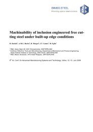
Us<strong>in</strong>g an optical laser system the crater pr<strong>of</strong>ile was<br />
analysed by per<strong>for</strong>m<strong>in</strong>g l<strong>in</strong>e scans perpendicular to the cutt<strong>in</strong>g<br />
edge. The tools were mounted on a fixed sample holder<br />
to guarantee the right (comparable) position <strong>of</strong> the l<strong>in</strong>e<br />
scan. The result is shown <strong>in</strong> figure 11. The maximum depth<br />
<strong>of</strong> the crater pr<strong>of</strong>ile <strong>of</strong> 11SMnPb37 is twice that <strong>of</strong> the <strong>in</strong>clusion<br />
eng<strong>in</strong>eered steel. It can be clearly seen that <strong>in</strong> case<br />
Figure 10. The comparison <strong>of</strong> the tool life <strong>of</strong> cutt<strong>in</strong>g <strong>in</strong>clusion eng<strong>in</strong>eered<br />
11SMn37 and regular 11SMnPb37. Cutt<strong>in</strong>g conditions: feed<br />
rate = 0.1 mm/rev, depth <strong>of</strong> cut = 1 mm, uncoated P10 tool, dry mach<strong>in</strong><strong>in</strong>g.<br />
Figure 11. Comparison <strong>of</strong> crater pr<strong>of</strong>iles <strong>of</strong> <strong>in</strong>clusion eng<strong>in</strong>eered<br />
11SMn37 and regular 11SMnPb37 after 4.1 km mach<strong>in</strong><strong>in</strong>g.<br />
Cutt<strong>in</strong>g conditions: speed = 300 m/m<strong>in</strong>, feed rate = 0.3 mm/rev,<br />
depth <strong>of</strong> cut = 2 mm, uncoated P10 tool, dry mach<strong>in</strong><strong>in</strong>g.<br />
<strong>of</strong> the leaded steel grade the crater wear is very pronounced<br />
at the vic<strong>in</strong>ity <strong>of</strong> the cutt<strong>in</strong>g edge. This is the well known<br />
characteristic feature observed <strong>in</strong> mach<strong>in</strong><strong>in</strong>g leaded steel<br />
grades.<br />
Conclusions<br />
– A thermodynamic model was developed based on the<br />
sub-regular solution <strong>of</strong> multi-component oxide systems<br />
applicable <strong>for</strong> slag-metal equilibrium.<br />
– The model is used as an onl<strong>in</strong>e tool at the ladle furnace <strong>of</strong><br />
the von Moos Stahl steel shop <strong>for</strong> controll<strong>in</strong>g deoxidation<br />
processes, slag-melt equilibration and melt-oxide <strong>in</strong>clusion<br />
equilibration. This allows the controlled production<br />
<strong>of</strong> exogenous and <strong>in</strong>digenous oxide <strong>in</strong>clusions <strong>in</strong> accordance<br />
with model prediction.<br />
– The controlled production <strong>of</strong> glassy oxides with adequate<br />
viscosity at the tool-chip <strong>in</strong>terface temperature can be<br />
used to improve the mach<strong>in</strong>ability <strong>of</strong> low carbon free cutt<strong>in</strong>g<br />
steels significantly. Us<strong>in</strong>g an <strong>in</strong>clusion eng<strong>in</strong>eered<br />
work piece the tool life time <strong>of</strong> an uncoated P10 tool<br />
could be tripled at cutt<strong>in</strong>g speeds <strong>in</strong> the range between<br />
200 and 400 m/m<strong>in</strong>.<br />
Acknowledgements<br />
The authors wish to acknowledge the contributions <strong>of</strong><br />
Chr. Hollmann <strong>of</strong> IFW (University <strong>of</strong> Hannover) <strong>for</strong> flank<br />
wear results and helpful discussion, M.Cobet <strong>of</strong> IWF (ETH<br />
Zürich) <strong>for</strong> crater wear measurements , and B. Heneka <strong>of</strong><br />
RJL Micro&Analytic GmbH <strong>for</strong> oxide <strong>in</strong>clusion characterization<br />
apply<strong>in</strong>g SEM/EDX techniques. The steel mak<strong>in</strong>g<br />
trials were per<strong>for</strong>med with the help <strong>of</strong> M. Kühnemund and<br />
W. Fuchs <strong>of</strong> von Moos Stahl.<br />
The fund<strong>in</strong>g support <strong>for</strong> the basic science research by<br />
NSERC, Canada is gratefully acknowledged <strong>in</strong> the <strong>for</strong>m <strong>of</strong><br />
a grant to R. Sowerby.<br />
(A2004005; received on 2 December 2003,<br />
<strong>in</strong> f<strong>in</strong>al <strong>for</strong>m on 11 February 2004)<br />
320 steel research <strong>in</strong>t. 75 (2004) No. 5