Create successful ePaper yourself
Turn your PDF publications into a flip-book with our unique Google optimized e-Paper software.
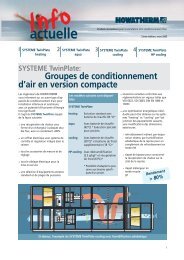
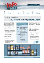
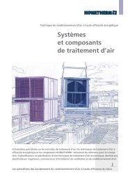
HP-WRG SYSTEM<br />
HYDROPLUS SYSTEM<br />
Thermodynamic heat recovery with > 99 % counter flow<br />
Technical information about<br />
high-performance cycle compound heat recovery systems<br />
based on countercurrent heat exchangers
2<br />
<strong>Systems</strong><br />
information<br />
orientation<br />
messages<br />
insights<br />
<strong>Systems</strong><br />
create helpful<br />
standards, saving us<br />
time to develop individual<br />
solutions.<br />
Heat recovery in<br />
air handling units<br />
<strong>HOWATHERM</strong> Klimatechnik has been specializing<br />
for nearly 30 years in the development<br />
and production of efficient<br />
systems for air handling applications to<br />
create and maintain comfortable indoor<br />
atmosphere for people.<br />
For pre-heating the outside air in the winter<br />
and cooling it in the summer, a variety<br />
of technical heat recovery systems are in<br />
use. A distinction is made between the following<br />
methods:<br />
Closed systems (heat pipe)<br />
Cycle compound countercurrent systems<br />
Plate-type heat exchangers<br />
Heat wheels<br />
Heat recuperators based on the heat<br />
pump principle<br />
HYGIENE SYSTEM<br />
ETA SYSTEM<br />
HP-WRG SYSTEM<br />
HYDROPLUS SYSTEM<br />
UV-UNIT<br />
With the exception of the cycle compound<br />
countercurrent system, all of the foregoing<br />
are associated with potential risks of moisture<br />
carryover or leakage air effects<br />
which disqualify them for use in hygiene<br />
applications.<br />
HP heat recovery system with feedback circuit
Heat recovery based on a recirculation<br />
system<br />
Conventional systems operate with fairly<br />
low efficiencies of around 40-50%. The<br />
requisite additional heat or chill had to be<br />
provided by supplementary heat exchangers<br />
in the supply airflow. However, our<br />
engineers have discovered a way of eliminating<br />
this very disadvantage.<br />
The HP* cycle compound heat<br />
recovery system<br />
This system comprises heat exchangers in<br />
the exhaust air and fresh air. Between the<br />
two heat exchangers, a heat transfer medium<br />
is recirculated to carry the thermal<br />
energy from one register to the other.<br />
Using this design, our <strong>HOWATHERM</strong> HP<br />
heat recovery system achieves efficiencies<br />
of up to 80%.<br />
*HP stands for high performance<br />
How do we achieve this high<br />
efficiency?<br />
Factor 1: Design optimization<br />
Our HP heat recovery system attains its<br />
high efficiency of up to 80% by combining<br />
multiple heat exchanger stages, each measuring<br />
not more than 300 mm in depth in<br />
conformance to VDI 3803 or VDI 6022. The<br />
length of the assembled array varies bet-<br />
Series arrangement of multiple heat exchanger<br />
stages in countercurrent mode<br />
ween 600 and 1200 mm, corresponding to<br />
about 16 to 32 rows in the airflow direction.<br />
To reduce the pressure loss, the in-flowing<br />
air velocity must not exceed 2.5 m/s.<br />
Factor 2: Accurate management<br />
of the intermediate medium<br />
Another important factor is the management<br />
of the heat transfer medium circulating<br />
between the heat exchangers. This<br />
medium must get maximum<br />
countercurrent<br />
exposure in the heat<br />
exchanger. We have the-<br />
0,8<br />
4<br />
n = 5 stages<br />
refore minimized crossflow<br />
and eliminated all<br />
0,7<br />
3<br />
co-current flow, since the<br />
latter in particular gives<br />
0,6<br />
2<br />
much lower transfer effi- 0,5<br />
ciencies.<br />
0,4<br />
1<br />
Our solution consists in<br />
arranging the individual<br />
heat exchanger stages in<br />
series in a specific countercurrent<br />
configuration<br />
0,3<br />
0 0,5 1,0 1,5 2,0<br />
Stages in series<br />
which must be strictly<br />
Heat exchange rate as a function of the heat<br />
adhered to. As a result of<br />
this design, our system<br />
attains a thermodynamic<br />
flow capacity ratio at k x A / WW = const.<br />
countercurrent rate of > 99%.<br />
Factor 3: Control<br />
Proper matching of the air mass flow and<br />
water mass flow is of critical importance.<br />
The maximum heat recovery rate is obtained<br />
if the heat flow capacity of the two<br />
media is the same. To this end, the flow of<br />
the intermediate medium (e.g., brine) is<br />
continuously controlled as a function of<br />
the air mass flow. This is the only way to<br />
ensure a maximum heat transfer even in<br />
part-load operation.<br />
WL = WW mL x cpL = mW x cpW At medium cp values<br />
(cpL and cpW ), we thus obtain:<br />
Construction<br />
mL / mW = cpW / cpL mit cpW = 4.19 kJ/kg K und cpL = 1.01 kJ/kg K it follows that:<br />
mL / mW = 4,19/1,01 = 4,15<br />
3
4<br />
Adjusting the speed<br />
ETA SYSTEM<br />
The complete<br />
solution<br />
Frequency converter ensures<br />
contantly optimized conditions<br />
Flow control via a throttle valve is an energy-inefficient<br />
process which results in increased<br />
pump wear.<br />
Adjusting the speed of the circulator<br />
pump through frequency control gives<br />
optimum conditions.<br />
The actual volumetric flow rate of the<br />
transfer medium is measured by a magnetic<br />
induction-type flow sensor with microprocessor<br />
technology and an alphanumeric<br />
display. An air flow measuring device<br />
(VSM) on the air side supplies the target<br />
signal (VSM for ETA systems). For details<br />
refer to our ETA SYSTEM product information.<br />
The complete solution - including<br />
instrumentation and control components.<br />
For our HP heat recovery system we supply<br />
a compact supply module comprising all<br />
hydraulic and instrumentation/control<br />
components.<br />
Designed for various air flows by accommodating<br />
various circuit alternatives, this<br />
module is optionally available with all<br />
equipment components. The benefits are<br />
obvious:<br />
Supply module with complete hydraulic<br />
system, even for expanded circuit configurations<br />
such as indirect heat/cooling<br />
supply via plate-type heat exchangers<br />
Recovery of removed heat from dehumidification<br />
and refrigerator wast heat is<br />
integrated into the module<br />
Free cooling is integrated into the<br />
module, or available indirectly via a<br />
plate-type heat exchanger<br />
Field equipment for air and brine side<br />
High operating reliability.<br />
Our delivery comprises a switchgear cabinet<br />
with DDC substation plus software tailored<br />
to the specific application.<br />
System adjustment and commissioning is<br />
performed under instruction of our expert<br />
fitters.<br />
Energy optimized fan ETA System Switchgear cabinet with DDC substation<br />
Enthalpy measurement<br />
To determine the mean heat capacity of<br />
the exhaust air under changing loads<br />
(temperature and moisture), a temperature<br />
sensor and an absolute moisture sensor<br />
detect the mean heat content. These parameters<br />
are used to determine the heat<br />
flow capacity ratio.<br />
Both variables are fed to the DDC substation<br />
and processed accordingly.<br />
The higher-order control system will then<br />
supply only the system-specific target<br />
values.
V SA<br />
0....10 V<br />
V ExtractA<br />
FI<br />
0....10 V<br />
t SA<br />
0....10 V<br />
0....10 V<br />
tExtractA X<br />
Heat recovery-H<br />
t FA<br />
t 2 t 1<br />
The anti-freezing function can be continuously<br />
controlled via a three-way valve by<br />
using the return flow temperature as the<br />
controlled variable. Defrosting of a frozen<br />
system (return flow tube surface temperature<br />
< -3°C) can also be performed continuously<br />
by adjusting the speed of the circulator<br />
pump.<br />
Performance testing<br />
The performance data of our HP cycle<br />
compound heat recovery system have been<br />
confirmed by neutral experts. At the Technical<br />
Academy of Central Switzerland,<br />
Lucerne University of<br />
Engineering, extensive measurements<br />
were carried out on an<br />
EN 45001-accredited test rig. Both thermal<br />
performance data, e.g., transfer rates, and<br />
pressure losses on the air and medium<br />
side were determined according to EN 308.<br />
Our calculated heat recovery rates of up to<br />
89 % were demonstrated in practice.<br />
M<br />
Heat recovery-C<br />
Schematic of the field equipment for heat recovery<br />
improvement with PLC substation<br />
SWISS<br />
T E S T I N G<br />
Pressure loss<br />
350<br />
300<br />
250<br />
200<br />
150<br />
100<br />
50<br />
50<br />
4 6 8 10 12 14 16 18 20 22 24<br />
Tube rows<br />
40<br />
30<br />
20<br />
4 6 8 10 12 14 16 18 20 22 24<br />
Tube rows<br />
In addition, the transfer<br />
rates and pressure losses<br />
of the heat exchanger<br />
units were neutrally and<br />
independently tested on RWTÜV<br />
test rigs.<br />
The performance data of our HP heat<br />
recovery system have also been attested in<br />
accordance<br />
with the<br />
European Standard<br />
EN 308 as part of the<br />
EUROVENT certification<br />
system for AHU systems<br />
(ID-No. AHU-98-05-001).<br />
2,5 m/s<br />
2,0 m/s<br />
1,5 m/s<br />
Transfer rates<br />
90 1,5 m/s<br />
2,0 m/s<br />
80<br />
2,5 m/s<br />
70<br />
60<br />
freiwillig<br />
GEPRÜFT<br />
Betriebscharakteristik-Übertragungsgrad-Druckverluste<br />
Transfer rates and<br />
pressure losses/<br />
tube rows<br />
5
7<br />
Secondary functions<br />
HP heat recovery<br />
system<br />
Patents<br />
Secondary functions<br />
of the HP heat recovery<br />
system<br />
Apart from the primary heat<br />
recovery function, a number<br />
of secondary functions can<br />
be implemented with this<br />
technology. The interposition<br />
of a heat transfer medium<br />
makes it possible to supply<br />
additional heating or cooling<br />
of the heat transfer medium<br />
without any additional heat<br />
exchangers on the air side,<br />
using water/water heat exchangers<br />
only.<br />
A direct supply of additional<br />
media (e.g., cold water) via a<br />
three-way valve is likewise<br />
feasible.<br />
For these functions (heating,<br />
cooling), a HP system with a<br />
heat recovery rate of at least<br />
70% is required (VDI 2071).<br />
Supply air<br />
indirect heating<br />
PHW<br />
PCW<br />
indirect cooling<br />
Extract air<br />
Outlet<br />
PCW<br />
direct cooling<br />
M<br />
M<br />
Heat recovery-C<br />
Venting devices<br />
Drain points<br />
Heat recovery-H<br />
Example of a HP countercurrent heat recovery system<br />
M<br />
Entry<br />
Downflow countercurrent tubing with automatic draining<br />
and venting. Outlet / Venting devices / Drain points<br />
Heat exchanger Patent Specification<br />
P 195 14 167 German Patent 1997<br />
P 198 08 753 German Patent 1999<br />
Downflow countercurrent tubing with automatic<br />
draining and venting<br />
Outlet / Venting devices / Drain points
Supply air<br />
Extract air<br />
M<br />
Power adjustment<br />
Heating Dehumidification<br />
Dehumidification cooling recovery<br />
Extract air<br />
Heating<br />
indirect supply<br />
Supply air<br />
M<br />
Hybrid indirect<br />
adiabatic cooling<br />
FI<br />
M<br />
M<br />
M<br />
Hybrid<br />
condenser recooling<br />
Refrigerating machine<br />
wast heat<br />
M<br />
Changeover valve<br />
Refrigerating<br />
Cooling<br />
Schematic of a typical embodiment: Summer operation<br />
FI<br />
M<br />
M<br />
M<br />
Power adjustment<br />
Exhaust air<br />
indirect supply<br />
M<br />
Schematic of a typical embodiment: Winter operation<br />
Fresh air<br />
Exhaust air<br />
Changeover valve<br />
Refrigerating<br />
Fresh air<br />
Expanded functional<br />
schematic showing<br />
secondary functions<br />
of the HP heat<br />
recovery system<br />
Schematic of a typical<br />
embodiment:<br />
Summer operation<br />
Cold recovery<br />
Indirect adiabatic evaporation<br />
cooling<br />
Refrigerating machine<br />
wast heat<br />
Indirect cooling<br />
Dehumidification circuit<br />
Dehumidification cold<br />
recovery through integral<br />
after-heating<br />
Winter operation<br />
Heat recovery<br />
Indirect heating<br />
5
8<br />
Design<br />
characteristics<br />
Adiabatic cooling<br />
In order to achieve the specified performance<br />
for the HP heat recovery system<br />
we have defined a number of minimum<br />
design characteristics.<br />
In the airflow direction the HP heat exchanger<br />
consists of about eight rows in<br />
the depth direction per register to make<br />
the system as easy to clean as possible.<br />
This design conforms fully to VDI 6022 and<br />
VDI 3803 conditions. Registers with installation<br />
depths exceeding 300 mm (staggered<br />
arrangement) must be split in the<br />
depth direction.<br />
The individual registers are thus accessible<br />
from each side and can be easily pulled<br />
out for convenient cleaning to meet applicable<br />
hygiene requirements.<br />
During the summer months, adiabatic cooling<br />
with the HP heat recovery systems has<br />
been found to give good results. The adiabatic<br />
cooling process is based on the use of<br />
an integral humidifier in the exhaust air-<br />
For enhanced corrosion protection our fins<br />
are plastic-coated or made entirely of copper.<br />
Aluminium fins are used for standard<br />
operating conditions. We thus provide<br />
ideal hygiene conditions due to optimum<br />
cleaning characteristics.<br />
The condensate need not pass the entire<br />
heat exchanger but will collect in the condensate<br />
tray after the individual registers.<br />
Depending on the application, we either<br />
use a staggered tube arrangement for<br />
optimum performance characteristics or an<br />
aligned tube system which minimizes pressure<br />
losses at a slight penalty in terms of<br />
transfer efficiency while being even less<br />
susceptible to fouling.<br />
The energy gained from the heat recovery<br />
process is used for cooling in both winter<br />
and summer operation, yielding further<br />
energy savings.<br />
Heat exchangers are optimized for thorough cleaning with water<br />
flow which humidifies the extract air adiabatically<br />
in several stages to cool it.<br />
HYDROPLUS SYSTEM
Principle and operation<br />
In our HYDROPLUS system, the heat exchanger<br />
that is a necessary part of any airhandling<br />
unit is simultaneously used as a<br />
contact body. It is sprayed with water via<br />
an array of nozzles in the extracted airflow<br />
on the air inlet side. Air from the<br />
system passing over the contact body is<br />
adiabatically humidified in this process.<br />
Design details<br />
A contact body is assembled from numerous<br />
aluminium fins arranged in parallel at<br />
2,5 mm centers. The fins carry a durable<br />
coating which increases its surface area<br />
substantially while giving it lasting hydrophilic<br />
properties, thus facilitating wetting.<br />
At the same time, the coating protects the<br />
contact body from corrosion.<br />
Air humidification - how is it<br />
achieved?<br />
The spray is applied evenly to the entire<br />
surface area of the contact body. The atomizing<br />
nozzles create a very fine droplet<br />
range. A film of water forms on the fins<br />
and is exposed to laminar airflow. An<br />
exchange of substances takes place between<br />
the water on the fins and the air<br />
passing over it.<br />
What are the benefits?<br />
The need for an additional humidifier<br />
body, with attendant pressure loss, is eliminated.<br />
We thus reduce the installation<br />
length of the entire unit, saving on investment<br />
cost.<br />
The combination of both systems provides<br />
further energy and cost savings.<br />
Here, too, the component is used as a heat<br />
exchanger and humidifier at the same<br />
time.<br />
The HP heat recovery / HYDROPLUS system<br />
is divided into several stages. Each stage<br />
comprises an adiabatic evaporation humidifier<br />
providing adiabatic humidification<br />
and hence, cooling, before the air enters<br />
the next stage. If we compare this multistage<br />
system to a single-stage arrangement,<br />
we find that the separation of the<br />
Hydroplus System - in combination with the HP heat recovery system<br />
<strong>HOWATHERM</strong><br />
Contact-<br />
humidifier<br />
HYDROPLUS system<br />
A contact humidifier<br />
for adiabatic air<br />
humidification<br />
HYDROPLUS<br />
SYSTEM<br />
9
10<br />
Performance gain<br />
Advantages of the<br />
combination system<br />
HYDROPLUS in com-<br />
bination with the HP<br />
heat recovery<br />
system<br />
Design data<br />
overall system into multiple stages provides<br />
a performance gain of about 20%.<br />
ϕ=1<br />
Successive cooling steps increase the gain<br />
of useful cold energy without causing a<br />
proportional increase in investment cost.<br />
Another important advantage lies in the<br />
fact that the adiabatic humidification is<br />
achieved via the evaporation humidifiers<br />
integrated into the heat exchanger. No<br />
additional pressure loss is incurred, as it<br />
x<br />
would be with separate humidifier bodies<br />
which would in turn increase the energy<br />
consumption.<br />
All in all, we eliminate the need for a<br />
separate humidifier body and reduce the<br />
pressure loss and installation length of the<br />
entire unit, all of which translates into<br />
investment cost savings.<br />
By combining an adiabatic humidification<br />
of the extract air with the heat recovery<br />
function in a single component, the following<br />
additional benefits are obtained:<br />
Reduced installation length<br />
More energy savings through reduced<br />
pressure loss<br />
Lower investment costs<br />
Retention of the fundamental advantages<br />
of a contact humidifier, specifically<br />
with regard to hygiene<br />
22,0°C 23,9°C 27,0°C 32,0°C<br />
40,0 %<br />
11,8 g/kg 11,9 g/kg 11,9 g/kg 11,9 g/kg<br />
63,1 l/h 45,7 l/h 45,4 l/h<br />
24,0 Pa 24,0 Pa 24,0 Pa<br />
60,0 %<br />
25,0°C 21,6°C 23,3°C<br />
26,0°C<br />
19,7°C 21,1°C 21,0°C<br />
11,9 g/kg 14,0 g/kg 14,7 g/kg 15,6 g/kg<br />
Air flow . . . . . . . . . . . . . . . . . .10.000 m 3 /h<br />
Cooling capacity . . . . . . . . . . . . . .33,1 kW<br />
Heat recovery efficiency . . . . . . . . .71,4 %<br />
Effective cooling efficiency . . . . . . . . .81,5 %<br />
Humidification efficiency . . . . . . . . . . .94,2 %<br />
Total operating water volume . .154,2 l/h at 2,5 bar<br />
Stage dx (g/kg) mw (l/h) bw (l/h) bw/mw Sz (s) Pz (s)<br />
1 2,1 25,2 63,1 2,5 7,0 53,0<br />
2 0,6 7,3 45,7 6,3 5,0 55,0<br />
3 0,9 10,9 45,4 4,2 5,0 55,0<br />
Legend: mw . . .Evaporation volume bw . . . .Operating water volume<br />
Sz . . . . Spray time Pz . . . . .Pause
Hygiene<br />
The water quality should conform to VDI<br />
Guidelines 3803.<br />
Operation and control<br />
HYDROPLUS SYSTEM<br />
Advantages<br />
The HYDROPLUS system as a contact humidifier<br />
moves very small water volumes<br />
with a low energy input. Water for humidification<br />
is supplied via the normal utility<br />
lines, without any pumps or rotary components.<br />
The necessary nozzle inlet pressure<br />
is about 2.5 bar when the system is in service;<br />
this is adjusted via a pressure reducing<br />
valve. Solenoid valves open and close<br />
the nozzle groups to be activated/deactivated<br />
in accordance with the required cooling<br />
capacity.<br />
Pre-investment analysis<br />
The use of a heat recovery system is not<br />
necessarily associated with a shorter payback<br />
period.<br />
Only a dynamic pre-investment analysis<br />
based on VDI 2071 or SWKl Guideline 89-1,<br />
which we will be glad to prepare for you<br />
as a service, can ultimately provide a reliable<br />
decision-making aid in selecting the optimum<br />
heat recovery system for your project.<br />
h<br />
HYDROPLUS SYSTEM<br />
I<br />
II<br />
III<br />
x<br />
h, x-diagram<br />
ϕ=1 Stage I<br />
Solenoid valve control<br />
Stage III<br />
Stage II<br />
Pressure<br />
Function Solenoid valve control<br />
Our HP cycle compound heat recovery<br />
system is the forward-looking alternative<br />
to conventional low-efficiency heat recovery<br />
solutions.<br />
Adiabatic cooling in particular can provide<br />
a range of interesting options to minimize<br />
or eliminate mechanical refrigerating requirements.<br />
It can thus provide a valuable<br />
tool for saving energy and reducing environmental<br />
loads.<br />
Operation and<br />
control<br />
HYDROPLUS<br />
SYSTEM<br />
Pre-investment<br />
analysis<br />
11
For further information contact our inhouse<br />
or agencies, or visit us on the<br />
Internet.<br />
<strong>HOWATHERM</strong> Klimatechnik GmbH<br />
Innovative Ventilation and Air Handling<br />
Technology<br />
Degussagelände 11-15<br />
55767 Brücken / Germany<br />
Postal address:<br />
Postfach 1461<br />
55762 Birkenfeld / Germany<br />
Phone: (+49) (0)6782-99 99- 0<br />
Telefax: (+49) (0)6782-99 99-10<br />
0700<strong>HOWATHERM</strong><br />
E-mail: info@howatherm.de<br />
www.howatherm.de<br />
We enjoy working with you.<br />
SchillerKrenz-Gestaltung<br />
©<strong>HOWATHERM</strong> KLIMATECHNIK GMBH<br />
P006-07/03