Centrifugal Pumps Design and Application 2nd ed - Val S. Lobanoff, Robert R. Ross (Butterworth-Heinemann, 1992)
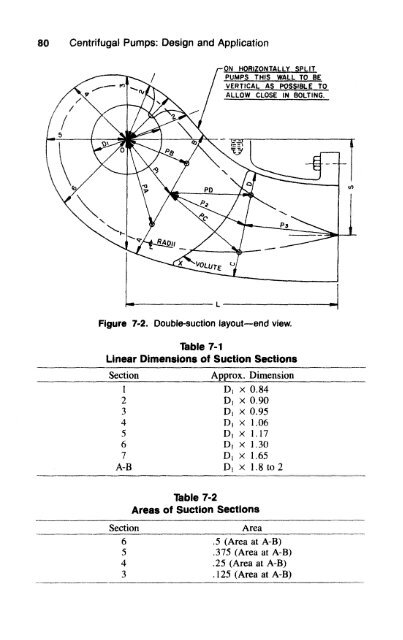
Double-Suction Pumps 79 two. Experience shows that this procedure will give misleading design factors and unfavorable test results. Design of the suction approach to the pump impeller for double-suction pumps will differ from the single-suction design. This will be covered in detail in the following paragraphs. Double-Suction Impeller The method for calculating impeller diameter, impeller width, number of vanes, and vane angularity is identical to the procedure for the singlesuction impeller described in Chapter 3. The method for impeller layout will also follow Chapter 3, with a double-suction impeller being considered two single-suction impellers back to back. With double entry the eye area is greater and the inlet velocity lower, thus reducing NPSHR. Side Suction and Suction Nozzle Layout The importance of hydraulic excellence in the design of liquid passage areas from suction nozzle to the impeller eye or eyes is quite often minimized or unfavorably adjusted for economic reasons. Experience shows that this approach leads to many field NPSH problems. The current trend in industry is one of reducing NPSHA; therefore, it is essential for optimum NPSHR that the design of the suction approach to the impeller eye be carefully controlled. We know from experience that in the design of the side suction inlet a certain amount of prerotation of the incoming liquid is desirable. To obtain this condition, the baffle (or splitter) is provided. This splitter is rotated 30° to 45 ° from suction centerline in the direction of pump rotation. The splitter will locate the radial section of zero flow, and the areas will progressively increase in both directions away from it. The following drawings and information must be available to design a side suction. 1. Volute layout. 2. Impeller layout. 3. Shaft or sleeve diameter at the impeller. 4. Suction nozzle size. Layout of the laterally displaced side suction should be done in two parts: 1. Sketch an approximate end view and profile (Figures 7-2 and 7-3) using the following guidelines:
80 Centrifugal Pumps: Design and Application Figure 7-2. Double-suction layout—end view. Table 7-1 Linear Dimensions of Suction Sections Section Approx. Dimension | 1 D, x 0,84 2 D, X 0.90 3 DI x 0.95 4 D| x 1.06 5 D! x 1.17 6 DJ X 1.30 7 D, x 1.65 A-B DJ X 1.8 to 2 Table 7-2 Areas of Suction Sections Section Area 6 .5 (Area at A-B) 5 .375 (Area at A-B) 4 .25 (Area at A-B) 3 .125 (Area at A-B)
- Page 44 and 45: Impeller Design 29 Figure 3-1. Requ
- Page 46 and 47: Impeller Design 31 Figure 3-4. Capa
- Page 48 and 49: Impeller Design 33 Step 8: Estimate
- Page 50 and 51: Impeller Design 35 Figure 3-7. Volu
- Page 52 and 53: impeller Design 37 (2) 5 , as final
- Page 54 and 55: Impeller Design 39 The vane develop
- Page 56 and 57: Impeller Design 41 Figure 3-12. Are
- Page 58 and 59: impeller Design 43 Figure 3-16. Inf
- Page 60 and 61: 4 General Pump Design It is not a d
- Page 62 and 63: General Pump Design 4? Figure 4-1.
- Page 64 and 65: General Pump Design 49 designed and
- Page 66 and 67: Volute Design 51 Figure 5-1. Volute
- Page 68 and 69: Volute Design 53 Figure 5-2. Radial
- Page 70 and 71: Volute Design 55
- Page 72 and 73: Volute Design 57 Figure 5-4. Effici
- Page 74 and 75: Volute Design 59 Figure 5-5. Typica
- Page 76 and 77: Volute Design 61 Figure 5-8. Univer
- Page 78 and 79: Volute Design S3 Manufacturing Cons
- Page 80 and 81: 6 Design of Multi-Stage Casing Mult
- Page 82 and 83: Design of Multi-Stage Casing 67 How
- Page 84 and 85: Design of Multi-Stage Casing 69 Fig
- Page 86 and 87: Design of Multi-Stage Casing 71 Fig
- Page 88 and 89: Design of Multi-Stage Casing 73 sec
- Page 90 and 91: Design of Multi-Stage Casing 75 Fig
- Page 92 and 93: 7 Double-Suction Pumps and Side-Suc
- Page 96 and 97: Double-Suction Pumps 81 Figure 7-3.
- Page 98 and 99: Double-Suction Pumps 83 LOCATION AR
- Page 100 and 101: 8 NPSH The expressions NPSHR and NP
- Page 102 and 103: NPSH 87 Predicting NPSHR The other
- Page 104 and 105: NPSH 89 Figure 8-4. Pressure loss b
- Page 106 and 107: NPSH 91 SUCTION VELOCITY TRIANGLES
- Page 108 and 109: NPSH 93 Figure 8-8. Performance cur
- Page 110 and 111: NPSH 95 Figure 8-10. Leakage across
- Page 112 and 113: NPSH 97 Figure 8-13. Plate inserts
- Page 114 and 115: NPSH 99 Figure 8-17. Influence of p
- Page 116 and 117: NPSH 101 Figure 8-19. Estimating K
- Page 118 and 119: NPSH 103 Step 3: Determine KI* From
- Page 120 and 121: Figure 8«22. Calculating NPSHA for
- Page 122 and 123: NPSH 107 Figure 8-24. NPSHR cavitat
- Page 124 and 125: NPSH 109 Notation KI Friction and a
- Page 126 and 127: Part 2 Application
- Page 128 and 129: 9 by Erik B. Fiske BW/JP Internatio
- Page 130 and 131: Vertical Pumps 115 Figure 9-2. Well
- Page 132 and 133: Vertical Pumps 117 Figure 9-4. Subm
- Page 134 and 135: Vertical Pumps 119 Figure 9-6. Inst
- Page 136 and 137: Vertical Pumps 121 Figure 9-8. Barr
- Page 138 and 139: Vertical Pumps 123 • Loading pump
- Page 140 and 141: Vertical Pumps 125 Wet Pit Pumps Th
- Page 142 and 143: Vertical Pumps 127 • Fresh water
80 <strong>Centrifugal</strong> <strong>Pumps</strong>: <strong>Design</strong> <strong>and</strong> <strong>Application</strong><br />
Figure 7-2. Double-suction layout—end view.<br />
Table 7-1<br />
Linear Dimensions of Suction Sections<br />
Section Approx. Dimension |<br />
1 D, x 0,84<br />
2 D, X 0.90<br />
3 DI x 0.95<br />
4 D| x 1.06<br />
5 D! x 1.17<br />
6 DJ X 1.30<br />
7 D, x 1.65<br />
A-B DJ X 1.8 to 2<br />
Table 7-2<br />
Areas of Suction Sections<br />
Section<br />
Area<br />
6 .5 (Area at A-B)<br />
5 .375 (Area at A-B)<br />
4 .25 (Area at A-B)<br />
3 .125 (Area at A-B)


