National Gypsum Construction Guide - 12th Edition
National Gypsum Construction Guide - 12th Edition
National Gypsum Construction Guide - 12th Edition

You also want an ePaper? Increase the reach of your titles
YUMPU automatically turns print PDFs into web optimized ePapers that Google loves.
12 TH EDITION<br />
<strong>National</strong> <strong>Gypsum</strong><br />
<strong>Construction</strong> <strong>Guide</strong><br />
09 20 00/NGC<br />
®
HOW TO USE THE NATIONAL GYPSUM COMPANY<br />
GYPSUM CONSTRUCTION GUIDE<br />
NATIONAL GYPSUM PRODUCTS FOR ALL YOUR<br />
BUILDING NEEDS<br />
Your <strong>National</strong> <strong>Gypsum</strong> Company “<strong>Gypsum</strong> <strong>Construction</strong><br />
<strong>Guide</strong>” has been carefully developed to provide you with a<br />
comprehensive guide to the entire range of <strong>National</strong> <strong>Gypsum</strong><br />
products. We have attempted to give you the most accurate,<br />
up-to-date information in a clear, concise, easy-to-read<br />
format. Because it is important for us to ensure our guide is<br />
user-friendly, we welcome your comments. Please write<br />
us at: <strong>National</strong> <strong>Gypsum</strong> Company Technical Services<br />
Department, 2001 Rexford Road, Charlotte, N.C. 28211 or<br />
call 1-800-NATIONAL (1-800-628-4662) U.S.A. or Canada.<br />
For your easy reference and accessibility to this information, we<br />
have placed all of our Sweet’s material in this section. For a<br />
complete copy of our literature call 1-800-NATIONAL.<br />
CAD DRAWINGS AND SPECIFICATIONS<br />
To assist you in your design process, all CAD drawings and<br />
specifications are available at www.nationalgypsum.com.<br />
Computer aided design (CAD) drawings are in DXF, DWG and<br />
GIF file formats. Specifications are in CSI three-part format and<br />
CSI page format. Additional specification options are provided in<br />
Masterspec and Manu-Spec.<br />
SUB-SECTION HEADING<br />
Each product in the section will be<br />
designated with a sub-section<br />
heading on the appropriate pages.<br />
COLOR ARROW HEAD<br />
Indicates next topic<br />
for a product, i.e.<br />
Description,<br />
Technical Data,<br />
Details,<br />
Specifications,<br />
Recommendations,<br />
Installation.<br />
®<br />
PAGE NUMBER<br />
<strong>National</strong> <strong>Gypsum</strong> Company Headquarters<br />
2001 Rexford Road<br />
Charlotte, North Carolina 28211<br />
(704) 365-7300<br />
Internet - www.nationalgypsum.com<br />
COPYRIGHT 2008 NATIONAL GYPSUM COMPANY<br />
Suspended Metal Lath Ceilings<br />
DESCRIPTION<br />
Metal lath suspensions are<br />
commonly made below<br />
virtually all types of<br />
construction for fire-rated<br />
and non fire-rated plaster<br />
ceilings. Framing of 1 1/2"<br />
C.R. channels are spaced<br />
up to 4' o.c. perpendicular<br />
to joists and are crossfurred<br />
with 3/4" C.R.<br />
channels spaced according<br />
to specifications for types<br />
and weight of metal lath.<br />
Lath is then properly<br />
lapped at sides and ends<br />
and tied every 6" to the<br />
3/4" channel.<br />
Where it is advisable to install<br />
unrestrained ceilings,<br />
having perimeters<br />
separated from adjacent<br />
walls or partitions,<br />
galvanized casing beads<br />
TECHNICAL DATA<br />
SIZE AND SPACING OF CHANNEL FOR SUSPENDED CEILINGS<br />
Center to Main Channel<br />
Center Spacing Size of (weight Maximum<br />
of Hangers Cold Rolled per 1000 ft.) Center to Center<br />
Along Channel Channel (305 M) Spacing of Channel<br />
up to 3' 1 1/2" 475 lbs. 4'<br />
(914 mm) (38.1 mm) (216 kg) (1219 mm)<br />
up to 3'6" 1 1/2" 475 lbs. 3'6"<br />
(1067 mm) (38.1 mm) (216 kg) (1067 mm)<br />
up to 4' 1 1/2" 475 lbs. 3'<br />
(1219 mm) (38.1 mm) (216 kg) (914 mm)<br />
DETAILS<br />
3/4" C.R.<br />
CHANNEL<br />
HANGER WIRE<br />
1 1/2" C.R.<br />
CHANNEL<br />
TIE WIRE<br />
GYPSUM PLASTER<br />
66 CASING BEAD<br />
FLEXIBLE DUST SEAL<br />
FINISHED WALL LINE<br />
SUSPENDED METAL LATH AT WALL (UNRESTRAINED)<br />
09210K<br />
Scale: 3" = 1'-0"<br />
should be installed around<br />
the periphery.<br />
Metal Lath is frequently used<br />
for furred as well as<br />
suspended ceilings.<br />
Metal lath is used for furring<br />
from wood, concrete and<br />
steel joists.<br />
RECOMMENDATIONS<br />
1. Control joints should be<br />
installed in ceilings without<br />
perimeter relief with a maximum<br />
distance between<br />
such joints of 30' with a<br />
maximum undivided area<br />
of 900 sq. ft. With perimeter<br />
relief, maximum distance<br />
is 50' with maximum<br />
undivided area of 2500<br />
sq.ft.<br />
2. Use three-coat plastering on<br />
metal lath.<br />
40 NATIONAL GYPSUM CONVENTIONAL PLASTER SYSTEMS<br />
SIZE AND SPACING OF CHANNEL FOR FURRED<br />
AND SUSPENDED CEILINGS<br />
3/4" (19.0 mm) C.R. Channel Maximum<br />
Center to Center Cross Furring 300 lbs. Furring<br />
Spacing of Hangers (136 kg)/1000 ft. (305 M) Spacing<br />
up to 3' (914 mm) 3/8" (9.5 mm) rib lath 24" (610 mm)<br />
up to 3' (914 mm) 3.4 lb. (1.5 kg) flat rib lath 19" (483 mm)<br />
up to 3'6" (1067 mm) 3.4 lb. (1.5 kg) mesh lath 16" (406 mm)<br />
up to 4' (1219 mm) 2.5 lb. (1.1 kg) mesh lath 12" (305 mm)<br />
MAXIMUM SPACING OF SUPPORTS FOR METAL LATH<br />
Type of Lath<br />
Support<br />
Spacing<br />
Weight of Lath<br />
lbs. per sq. yd. (kg/m2 Diamond Mesh<br />
)<br />
(flat expanded) 16" (406 mm) 3.4 (1.9)<br />
Flat Rib 16" (406 mm) 2.75 (1.5)<br />
19" (483 mm) 3.4 (1.9)<br />
3/8" (9.5 mm) Rib 24" (610 mm) 3.4 (1.9)<br />
1 1/2" C.R.<br />
CHANNEL<br />
1 1/2" C.R.<br />
CHANNEL<br />
HANGER WIRE<br />
3/4" C.R.<br />
CHANNEL<br />
GYPSUM<br />
PLASTER<br />
66 CASING BEAD<br />
METAL LATH<br />
METAL LATH<br />
NO. 15<br />
EXPANSION JOINT<br />
LIGHTING TROFFER<br />
SUSPENDED METAL LATH CONTROL JOINT<br />
09210O<br />
09210M<br />
Scale: 1 1/2" = 1'-0"<br />
Scale: 3" = 1'-0"<br />
SUB-SECTION NAME<br />
Repeats the name of the<br />
current sub-section.<br />
TRADEMARKS<br />
The following names are trademarks owned by <strong>National</strong><br />
<strong>Gypsum</strong> Company or its subsidiary, <strong>National</strong> <strong>Gypsum</strong><br />
Properties, LLC:<br />
DURABASE ®<br />
DURASAN ®<br />
EASY FINISH ®<br />
EDGE GRIP TM<br />
EXCELLENCE ACROSS<br />
THE BOARD ®<br />
e 2 XP <br />
E-Z STRIP ®<br />
FIRE-SHIELD ®<br />
FIRE-SHIELD C TM<br />
GOLD BOND ®<br />
GOLD BOND 54 ®<br />
GRIDMARX ®<br />
GRIDSTONE ®<br />
GYPSOLITE ®<br />
HIGH FLEX ®<br />
HI-ABUSE ®<br />
HI-IMPACT ®<br />
KAL-KORE ®<br />
KAL-KORNER BEAD ®<br />
CAD DRAWING FILE<br />
NUMBER<br />
KAL-KOTE ®<br />
KAL-MESH ®<br />
MULTI-FLEX ®<br />
NGC ®<br />
1-800 NATIONAL ®<br />
PERFECT SPRAY ®<br />
PERMABASE ®<br />
PERMABASE FLEX ®<br />
PROFORM ®<br />
SEASPRAY MVR ®<br />
SHAFTLINER ®<br />
SHAFTLINER XP ®<br />
SOUNDBREAK<br />
STA-SMOOTH ®<br />
TRIPLE-T ®<br />
ULTRA TM<br />
UNI-KAL ®<br />
X-KALIBUR ®<br />
XP ®<br />
GRAPHICS, ILLUSTRATIONS AND<br />
PHOTOGRAPHY<br />
Each product grouping is<br />
full of informative graphics and<br />
photography as a visual aid in<br />
identifying products, uses and<br />
installation.<br />
CAD DRAWINGS<br />
These drawings are included where<br />
appropriate to assist architects and<br />
specifiers with detailed drawings.
Charlotte, North Carolina, is the home of the new <strong>National</strong><br />
<strong>Gypsum</strong> Company.<br />
TABLE OF CONTENTS<br />
Product Specification Directory .........................................................................3<br />
Sound and Fire Rated Assemblies ......................................................................8<br />
Quick Selector for Fire and Sound Rated Systems..............................................9<br />
<strong>Gypsum</strong> Plaster Partitions – Metal Lath.........................................................11<br />
Plaster Fireproofing Columns (10WF40 or heavier)......................................12<br />
Plaster Fireproofing Beams (8WF24 or heavier) ...........................................12<br />
Veneer Plaster Partitions – Wood and Steel Framing....................................12<br />
<strong>Gypsum</strong> Board Partitions – Wood Framing (Load-Bearing)..........................12<br />
<strong>Gypsum</strong> Board Partitions – Steel Framing.....................................................14<br />
<strong>Gypsum</strong> Board Partitions – Steel Framing (Load-Bearing) ............................18<br />
<strong>Gypsum</strong> Board Partitions – Durasan Prefinished <strong>Gypsum</strong> Board..................18<br />
<strong>Gypsum</strong> Board Partitions – Solid..................................................................19<br />
<strong>Gypsum</strong> Board Partitions – Shaftwalls, Area Sep. Walls...............................20<br />
<strong>Gypsum</strong> Board Column Fireproofing............................................................21<br />
<strong>Gypsum</strong> Board Beam Fireproofing...............................................................22<br />
<strong>Gypsum</strong> Board Floor/Ceilings – Wood Framing...........................................22<br />
<strong>Gypsum</strong> Board Roof/Ceilings – Wood Framing ...........................................23<br />
<strong>Gypsum</strong> Board Floor/Ceilings – Steel Framing .............................................24<br />
<strong>Gypsum</strong> Board Roof/Ceilings – Steel Framing..............................................26<br />
<strong>Gypsum</strong> Board Horizontal Shaftwall Duct Protection..................................26<br />
Gold Bond<br />
09 23 00<br />
09 26 13<br />
® BRAND <strong>Gypsum</strong> Sheathing and e2XP Extended Exposure Sheathing ....27<br />
Conventional Plaster Systems...........................................................................33<br />
Veneer Plaster Systems ....................................................................................43<br />
<strong>Gypsum</strong> Board Systems ...................................................................................57<br />
Gold Bond ® BRAND GridMarX ® <strong>Gypsum</strong> Board................................................64<br />
Gold Bond ® BRAND <strong>Gypsum</strong> Board ..................................................................65<br />
Gold Bond ® BRAND Fire-Shield ® <strong>Gypsum</strong> Board ..............................................66<br />
Gold Bond ® BRAND Sta-Smooth <strong>Gypsum</strong> Board ...............................................67<br />
Gold Bond ® BRAND XP ® <strong>Gypsum</strong> Board ...........................................................70<br />
Gold Bond ® BRAND Exterior Soffit Board...........................................................71<br />
Gold Bond ® BRAND 1" Fire-Shield ® Shaftliner....................................................73<br />
Gold Bond ® BRAND 1" Fire-Shield ® Shaftliner XP ® .............................................74<br />
High Flex BRAND <strong>Gypsum</strong> Board ......................................................................75<br />
Gold Bond ® BRAND High Strength Ceiling Board..............................................77<br />
Gold Bond ® BRAND Hi-Abuse ® XP ® 06 16 43<br />
09 29 00<br />
09 29 00<br />
09 29 00<br />
09 29 00<br />
09 29 00<br />
09 29 00<br />
09 29 00<br />
09 29 00<br />
09 29 00<br />
09 29 00<br />
09 29 00<br />
09 29 00<br />
<strong>Gypsum</strong> Board ..........................................78<br />
<strong>National</strong> <strong>Gypsum</strong> Company is a fully integrated manufacturer<br />
and supplier of building and construction products worldwide.<br />
Our primary emphasis is on Gold Bond ® BRAND gypsum<br />
board, ProForm ® BRAND joint treatment products, PermaBase ®<br />
BRAND cement board, and gypsum plaster systems.<br />
Based in Charlotte, NC, the privately held <strong>National</strong> <strong>Gypsum</strong><br />
Company operates more than 40 facilities throughout the<br />
U.S. and Canada.<br />
GENERAL REFERENCE<br />
Hi-Impact ® BRAND XP ® <strong>Gypsum</strong> Board.........................................81<br />
SoundBreak <strong>Gypsum</strong> Board ....................................................84<br />
Gridstone BRAND Ceiling Panels...................................................86<br />
Gridstone BRAND Cleanroom Ceiling Panels ...............................87<br />
Gridstone ® BRAND Hi-Strength Ceiling Panels .............................88<br />
Gold Bond ® 09 29 00<br />
09 29 00<br />
09 29 00<br />
09 29 00<br />
09 29 00<br />
09 29 00<br />
BRAND Foil Back <strong>Gypsum</strong> Board .............................89<br />
09 29 00 <strong>Gypsum</strong> Systems Nonload-Bearing Steel Frame Partitions .........90<br />
09 29 00 Drywall Metal Framing ...............................................................93<br />
09 29 00 Accessories .................................................................................94<br />
09 29 00 Steel Frame Ceilings/Furring Channels or Studs...........................99<br />
09 29 00 Wood Frame Walls and Ceilings ..............................................101<br />
09 29 00 Resilient Furring Channel <strong>Construction</strong> ....................................106<br />
09 29 00 <strong>Gypsum</strong> Board Over Masonry .................................................108<br />
Solid Laminated Partitions.........................................................110<br />
ProForm ® BRAND Joint Treatment ...............................................112<br />
ProForm ® BRAND Texture Products .............................................115<br />
Levels of <strong>Gypsum</strong> Board Finish.................................................118<br />
Cavity Shaftwall Systems...........................................................123<br />
Horizontal Shaftwall Duct and Ceiling Assemblies...................137<br />
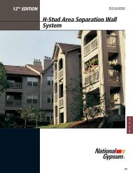
H-Stud Area Separation Wall System ........................................139<br />
PermaBase ® 09 29 00<br />
09 29 00<br />
09 29 00<br />
09 29 00<br />
09 21 16.23<br />
09 21 16.23<br />
09 21 16.33<br />
09 28 00<br />
BRAND Cement Board.............................................145<br />
INDEX Index .........................................................................................157<br />
INDEX<br />
Index of CAD Detail Drawings..................................................161<br />
Our vision: To be recognized as the industry leader for extraordinary<br />
service and products that consistently meet our customers’ toughest<br />
standards.<br />
Driving and sustaining our Vision are these core Values:<br />
Customer satisfaction as our priority<br />
Honesty, integrity, fairness and respect<br />
Communications and openness with all those with whom we deal<br />
Teamwork, empowerment and continuous improvement<br />
Work hard, be safe, and have fun<br />
NATIONAL GYPSUM GENERAL REFERENCE<br />
1<br />
GENERAL<br />
REFERENCE
NATIONAL GYPSUM COMPANY<br />
<strong>National</strong> <strong>Gypsum</strong>’s Technology Innovation Center is located in<br />
Charlotte, North Carolina. <strong>National</strong> <strong>Gypsum</strong> has always held a leadership<br />
role in the development of gypsum based products and systems.<br />
Many of today’s most innovative gypsum, joint treatment and cement<br />
board products and systems were developed, tested and introduced by<br />
<strong>National</strong> <strong>Gypsum</strong> Company.<br />
YOUR TECHNICAL<br />
RESOURCE<br />
Today, more than ever, clear,<br />
accurate information is vital<br />
to every construction job.<br />
The challenges of construction<br />
continue to grow:<br />
increasingly innovative<br />
building designs, tighter<br />
budgets, tighter schedules,<br />
and the continuing development<br />
of new materials<br />
and construction techniques.<br />
A NETWORK OF<br />
TECHNICAL SUPPORT<br />
In keeping with the corporate<br />
mission to become the preferred<br />
supplier for our customers,<br />
<strong>National</strong> <strong>Gypsum</strong><br />
has made a total commitment<br />
to technical assistance<br />
and created a network<br />
of support to provide<br />
valuable assistance at every<br />
stage of a project’s development.<br />
Field Representation. Before<br />
construction begins, while<br />
plans and specifications are<br />
being produced, these<br />
experienced, trained professionals<br />
provide<br />
technical consultation<br />
in selecting, specifying<br />
and using gypsum-based<br />
building materials.<br />
During the construction<br />
phase, our Field<br />
Representatives have the<br />
experience and the training<br />
to assure that the <strong>National</strong><br />
<strong>Gypsum</strong> products you need<br />
and specify are right for<br />
the job. They are backed<br />
up by thoroughly trained<br />
Customer Service<br />
Representatives who can<br />
also help with product<br />
selection and purchase.<br />
Continuing Research. Because<br />
the building industry and<br />
building codes are constantly<br />
changing, <strong>National</strong><br />
<strong>Gypsum</strong> maintains a fullscale<br />
research center that<br />
continually tests and evaluates<br />
products, applications,<br />
construction systems and<br />
techniques.<br />
Immediate Answers. Of<br />
course, there are times<br />
when you need an answer<br />
to a pressing situation or<br />
question. For this reason,<br />
<strong>National</strong> <strong>Gypsum</strong> has set<br />
up our Technical<br />
Assistance Hotline:<br />
1-800-NATIONAL<br />
(1-800-628-4662).<br />
One toll-free phone call gives<br />
a direct, personal link to a<br />
technical expert with up-todate<br />
knowledge of specifications,<br />
building codes,<br />
product information and<br />
much more.<br />
QUALITY IS SYSTEMATIC<br />
At the <strong>National</strong> <strong>Gypsum</strong><br />
Research Center, we<br />
concentrate not only on<br />
building products individually<br />
but also on complete<br />
construction systems. In<br />
2 NATIONAL GYPSUM QUICK SELECTOR/GENERAL REFERENCE<br />
such systems, products<br />
are evaluated<br />
together as complete<br />
building<br />
assemblies – walls,<br />
partitions, floors<br />
and ceilings.<br />
Before <strong>National</strong><br />
<strong>Gypsum</strong> releases a<br />
system to the building<br />
industry, the system<br />
is thoroughly<br />
tested and the<br />
results are correlated<br />
and charted, making<br />
it easier for the<br />
builder or architect<br />
to match a system to<br />
his needs or to<br />
building codes. This<br />
extensive database<br />
of technical information<br />
is made<br />
available to you not<br />
only through technical<br />
bulletins such as<br />
this one, but also<br />
through our technical<br />
support network.<br />
The construction systems<br />
referred to in this manual<br />
are designed and tested<br />
with material manufactured<br />
by <strong>National</strong> <strong>Gypsum</strong>.<br />
Substitutions of other<br />
products or brands for<br />
<strong>National</strong> <strong>Gypsum</strong> Products<br />
are not recommended.<br />
Field Installation of tested systems<br />
must be identical to<br />
the laboratory installation<br />
to produce optimum performance<br />
of these systems,<br />
though duplication of controlled,<br />
laboratory results<br />
in such field installations is<br />
not guaranteed.<br />
<strong>National</strong> <strong>Gypsum</strong>’s own<br />
patented Calcidyne system<br />
heats the land plaster to<br />
remove 75% of the water<br />
which is chemically combined<br />
in the gypsum molecules.<br />
Performance tests are<br />
conducted according to<br />
accepted national standards<br />
under controlled laboratory<br />
conditions to minimize<br />
variances and to permit<br />
comparison of test<br />
results of all types of systems,<br />
similar and dissimilar.<br />
Detailed recommendations<br />
are contained in each section.<br />
Architects, structural<br />
engineers or others who<br />
are responsible for field<br />
installations must make<br />
their own determinations<br />
concerning the applicability<br />
of the laboratory performance<br />
test results to the<br />
design or construction of<br />
any specific structure.<br />
<strong>National</strong> testing organizations frequently participate in the<br />
many product tests conducted at NGC Testing Services. Fire,<br />
acoustical, structural and analytical test laboratories are<br />
available commercially through NGC Testing Services SM for<br />
other manufacturers and research interests. For information,<br />
call 716-873-9750 or www.NGCTestingServices.com.
PRODUCT SPECIFICATION DIRECTORY<br />
FOREWORD<br />
This directory is designed to provide a convenient, up-to-date<br />
reference to some of the products marketed by <strong>National</strong><br />
<strong>Gypsum</strong> Company, and to the ASTM and Federal<br />
Specifications with which they comply.<br />
The General Services Administration has cancelled many Federal<br />
procurement documents. These have been superseded by<br />
ASTM Specifications. Federal Specifications are listed for<br />
reference.<br />
GENERAL REFERENCE<br />
For the key to Federal Specification, gypsum board and joint<br />
treatment product designations (Type, Form, etc.), refer to<br />
table on page 7.<br />
This is to certify that the following materials comply in all<br />
respects with listed specifications.<br />
GYPSUM BOARD PRODUCTS Specification Standards<br />
Product Description and Use ASTM Federal<br />
Regular <strong>Gypsum</strong> Fire resistant. Will take decoration after proper C 1396 SS-L-30D Type III<br />
Board or Sta-Smooth surface preparation of interior walls and ceilings.<br />
XP <strong>Gypsum</strong> Board 1/2" (12.7 mm) gypsum board with a<br />
moisture resistant gypsum core and mold/mildew<br />
resistant purple paper. Will take decoration after<br />
proper surface preparation of interior walls and ceilings.<br />
C 1396 SS-L-30D Type III<br />
Fire-Shield <strong>Gypsum</strong> 1/2" (12.7 mm) and 5/8" (15.9 mm) gypsum C 1396 SS-L-30D Type III<br />
Board (Includes “C”) board with specially processed core highly<br />
resistant to fire; type X core.<br />
Type X Grade X<br />
XP Fire-Shield <strong>Gypsum</strong> 1/2" (12.7 mm) and 5/8" (15.9 mm) gypsum C 1396 SS-L-30D Type III<br />
Board (Includes “C”) board with a moisture resistant gypsum<br />
core highly resistant to fire and mold/mildew<br />
resistant purple paper; type X core.<br />
Type X Grade X<br />
SoundBreak 5/8" (15.9 mm) acoustically enhanced gypsum C 1396 SS-L-30D Type III<br />
<strong>Gypsum</strong> Board board used in construction of high rated STC<br />
assemblies.<br />
Foil Back <strong>Gypsum</strong> Standard gypsum board with aluminum foil C 1396 SS-L-30D Type III<br />
Board on backside providing vapor retarder for interior<br />
walls and ceilings.<br />
Form C<br />
Fire-Shield Shaftliner 1" (25.4 mm) thick, 2' (610 mm) wide, for solid C 1396 SS-L-30D Type IV<br />
(Includes XP) partitions, shaft walls and Area Separation Walls;<br />
type X core.<br />
Type X Grade X<br />
Regular or Fire-Shield <strong>Gypsum</strong> board with extra resistance to C 1396 None<br />
Exterior Soffit Board moisture and sagging used for exterior soffit. Type X<br />
<strong>Gypsum</strong> Durasan Prefinished <strong>Gypsum</strong> board with a vinyl surface, combines C 1396 SS-L-30D Type III<br />
Board Regular <strong>Gypsum</strong> Board texture and pattern in colors. No decoration required. Class 3<br />
Durasan Prefinished <strong>Gypsum</strong> board with a vinyl surface, combines C 1396 SS-L-30D Type III<br />
Fire-Shield <strong>Gypsum</strong> Board texture and pattern in colors; type X core. Type X Grade X Class 3<br />
High Flex <strong>Gypsum</strong> Board 1/4" (6.4 mm) flexible gypsum board designed for<br />
use in radius wall and ceiling construction.<br />
C 1396 SS-L-30D Type III<br />
High Strength 1/2" (12.7 mm) gypsum board with core formulated C 1396 SS-L-30D Type III<br />
Ceiling Board to provide increased sag resistance.<br />
Hi-Abuse XP Fire-Shield 5/8" (15.9 mm) gypsum board with heavy abrasion C 1396 SS-L-30D Type III<br />
<strong>Gypsum</strong> Board resistant mold/mildew resistant purple paper and a<br />
special core to provide greater resistance to surface<br />
indentation; type X core.<br />
Type X Grade X<br />
Hi-Impact XP Fire-Shield 5/8" (15.9 mm) gypsum board with heavy C 1396 SS-L-30D Type III<br />
<strong>Gypsum</strong> Board abrasion resistant mold/mildew resistant purple<br />
paper and a special moisture resistant gypsum core<br />
backed with reinforcing fiber glass mesh; type X core.<br />
Type X Grade X<br />
Gridstone Ceiling Panels 1/2" x 2' x 2' (12.7 mm x 610 mm x 610 mm) C 1396 None<br />
1/2" x 2' x 4' (12.7 mm x 610 mm x 1219 mm) Type X, Class 1;<br />
gird panels with Fire-Shield G type X core and E 1264, Type XX,<br />
vinyl laminate. Patterns E, G<br />
NATIONAL GYPSUM PRODUCT SPECIFICATION DIRECTORY<br />
3<br />
GENERAL<br />
REFERENCE
GYPSUM BOARD PRODUCTS (cont.) Description and Use ASTM Federal<br />
Gridstone Hi-Strength 5/16" x 2' x 2' (7.9 mm x 610mm x 610 mm) C 1396 None<br />
Ceiling Panels 5/16" x 2' x 4' (7.9 mm x 610 mm x 1219 mm) Class 1<br />
grid panels with non-combustible gypsum core<br />
and vinyl laminate.<br />
<strong>Gypsum</strong> Gridstone CleanRoom 1/2" x 2' x 2' (12.7 mm x 610 mm x 610mm) C 1396 None<br />
Board Ceiling Panels 1/2" x 2' x 4' (12.7 mm x 610 mm x 1219 mm) Type X, Class 1;<br />
grid panels with Fire-Shield G type x core and vinyl E 1264, Type XX,<br />
laminate. Completely sealed on face, back and edges. Patterns E, G<br />
Durabase <strong>Gypsum</strong> Board 5/16" (7.9 mm), 3/8" (9.5 mm), 1/2" (12.7 mm), C 1396 None<br />
and 5/8" (15.9 mm) gypsum board for printing<br />
application or laminating base.<br />
Regular Jumbo <strong>Gypsum</strong> 1/2" (12.7 mm) gypsum board to be used as C 1396 SS-L-30D Type II<br />
Sheathing a sheathing for exterior wall construction.<br />
Fire-Shield Jumbo 5/8" (15.9 mm) gypsum board to be used as C1396 SS-L-30D Type II<br />
<strong>Gypsum</strong> Sheathing sheathing for fire rated exterior wall construction; Type X Grade X<br />
Sheathing type X core.<br />
e 2 XP Extended 1/2” (12.7 mm) Regular with a coated fiberglass mat C1177 SS-L0-30D Type II<br />
Exposure Sheathing used as a sheathing for exterior wall construction. and applicable sections of<br />
C1396<br />
e 2 XP Extended 5/8” (15.9 mm) Type X with a coated fiberglass mat C1177 SS-L0-30D Type II<br />
Exposure Sheathing used as a sheathing for fire-rated exterior wall and applicable sections of Grade X<br />
construction C1396<br />
LATH, DRYWALL JOINT TREATMENT, TEXTURES AND ACCESSORIES Specification Standards<br />
Product Description and Use ASTM Federal<br />
Kal-Kore Plaster Base 3/8" (9.5 mm), 1/2" (12.7 mm) gypsum base<br />
for veneer plaster systems.<br />
C 1396 SS-L-30D Type VI<br />
Kal-Kore Fire-Shield 1/2" (12.7 mm), 5/8" (15.9 mm) gypsum base for C 1396 SS-L-30D Type VI<br />
Lath Plaster Base (includes “C”) veneer plaster systems; type X core. Type X Grade X<br />
Regular or Fire-Shield <strong>Gypsum</strong> base with special core to provide C 1396 SS-L-30D TypeVI<br />
Hi-Abuse Kal-Kore greater resistance to surface indentation. Type X Grade X<br />
Plaster Base Designed for high abuse areas.<br />
ProForm All Purpose A conventional full-weight ready mix joint compound C 475 SS-J-570B<br />
Joint Compound used for all phases of drywall finishing.<br />
ProForm XP<br />
Joint Compound<br />
A conventional full-weight ready mix joint compound<br />
formulated for additional mold resistance.<br />
C 475 SS-J-570B<br />
ProForm Multi-Use A ready mix compound that combines the best attributes C 475 SS-J-570B<br />
Joint Compound of All Purpose and Lite for use in all phases of drywall<br />
finishing<br />
Joint ProForm Lite A full “Lite” weight ready mix for use in finishing gypsum C 475 SS-J-570B<br />
Treatment Joint Compound board, gypsum board joints, spotting fasteners and finishing<br />
accessories.<br />
ProForm Ultra An all purpose joint compound that pulls and sands easier C 475 SS-J-570B<br />
Joint Compound than conventional ready mix with up to 50% less shrinkage.<br />
ProForm Taping Ready mixed joint compound used to enhance bond when C 475 SS-J-570B<br />
Joint Compound embedding joint tape and applying cornerbeads and<br />
accessories.<br />
ProForm Topping Ready mixed topping compound designed as a finish C 475 SS-J-570B<br />
Joint Compound coat over joint compound.<br />
ProForm Texture Grade A nonaggregated, ready mixed material formulated for C 475 SS-J-570B<br />
texturing interior walls and ceilings.<br />
ProForm Triple-T Triple-T is an all-purpose powder product to be job mixed C 475 SS-J-570B<br />
Compound with water. It is recommended for tape application, finishing<br />
and texturing.<br />
ProForm Sta-Smooth, A setting type powder compound used for joint finishing. C 475 SS-J-570B<br />
Sta-Smooth Lite, and<br />
Sta-Smooth HS Joint<br />
Compounds<br />
4 NATIONAL GYPSUM PRODUCT SPECIFICATION DIRECTORY
GENERAL REFERENCE<br />
LATH, DRYWALL JOINT TREATMENT, TEXTURES AND ACCESSORIES (cont.) Specification Standards<br />
Product Description and Use ASTM Federal<br />
Textures ProForm Perfect Spray A white, aggregated spray texture for interior use on None None<br />
Textures walls and ceilings.<br />
ProForm Perfect Spray A white, nonaggregated spray texture for interior use on None None<br />
EM Textures walls and ceilings.<br />
<strong>Gypsum</strong> Board Cornerbead* Used to protect exterior corners. C 1047 None<br />
<strong>Gypsum</strong> Board Casing Bead* Used to reinforce and trim around doors and windows. C 1047 None<br />
Arch Cornerbead* Used straight for exterior corners or may be snipped and<br />
bent to form arches.<br />
C 1047 None<br />
ProForm Joint Tape A paper tape for concealment of gypsum board joints. C 475** SS-J-570B**<br />
ProForm Fiberglass A self-adhering glass fiber mesh tape to be used only with C 475 None<br />
Mesh Tape<br />
ProForm Multi-Flex<br />
Tape Bead<br />
setting compounds.<br />
Used to form inside or outside corners that are less or<br />
greater than 90<br />
None None<br />
o Accessories<br />
.<br />
E-Z Strip Expansion Joint* Vinyl extrusion used as an expansion or control joint for<br />
drywall and veneer plaster walls and ceilings.<br />
C 1047 None<br />
.093 Zinc Expansion Joint* All zinc part used as an expansion or control joint for<br />
drywall and veneer plaster walls and ceilings.<br />
C 1047 None<br />
*<strong>National</strong> <strong>Gypsum</strong> does not manufacture these products.<br />
FIRE AND SMOKE STOP COMPOUND Specification Standards<br />
Product Description and Use ASTM Federal<br />
ProForm Sta-Smooth Setting type product formulated to provide protection in None None<br />
FS 90 Compound fire stopping applications through gypsum and other fire<br />
rated assemblies. Meets ASTM E 814 and ANSI/UL 1479.<br />
PLASTER PRODUCTS AND ADDITIVES Specification Standards<br />
Product Description and Use ASTM Federal<br />
Gold Bond Two-Way For use with job-mixed aggregate. Machine spray or C 28 SS-P-00402B<br />
Hardwall <strong>Gypsum</strong> Plaster trowel application. Type II<br />
Basecoat Gold Bond Mill-mixed with perlite. Add only water on the job. C 28 SS-P-00402B<br />
Plasters Gypsolite Plaster Type I<br />
Kal-Kote Base Plaster Basecoat plaster for veneer system. Add only water on the C 587 SS-P-00402B<br />
job. Type VI<br />
Gold Bond <strong>Gypsum</strong> Used with lime for trowel finish or run-in-place ornamental C 28 SS-P-00402B<br />
Gauging Plaster work. Type V<br />
Gold Bond <strong>Gypsum</strong> Used with lime for run-in-place ornamental work or with C 59 SS-P-00402B<br />
Moulding Plaster water only for precast ornaments. Type V<br />
Finish Kal-Kote Smooth Finish Hard, thin, smooth finish over Kal-Kote base plaster or C 587 SS-P-00402B<br />
Plasters Plaster conventional basecoat plasters. Type VI<br />
Kal-Kote Texture Hard, thin, textured finish over Kal-Kote base plaster or C 587 SS-P-00402B<br />
Finish Plaster conventional basecoat plasters. Type VI<br />
Uni-Kal Veneer Plaster One coat finish over Kal-Kore. Can also be used as finish C 587 SS-P-00402B<br />
over Kal-Kote base or conventional plaster. Type VI<br />
X-KALibur Extended set time, one coat finish over Kal-Kore. Can C 587 SS-P-00402B<br />
Veneer Plaster also be used as finish over Kal-Kote base or conventional<br />
basecoat plasters.<br />
Type VI<br />
Special<br />
Additives<br />
Gold Bond Retarder<br />
Gold Bond Accelerator<br />
A powder used to slow the set of gypsum plaster.<br />
A powder used to quicken the set of gypsum plaster.<br />
None<br />
None<br />
None<br />
None<br />
**Paper tape meeting these specifications available on special order.<br />
NATIONAL GYPSUM PRODUCT SPECIFICATION DIRECTORY<br />
5<br />
GENERAL<br />
REFERENCE
VENEER PLASTER ACCESSORIES Specification Standards<br />
Product Description and Use ASTM Federal<br />
Kal-Korner Bead* Used to protect exterior corners in veneer plaster systems. C 1047 None<br />
Expanded Veneer Cornerbead* Used as an alternate to the Kal-Korner bead for exterior corners. C 1047 None<br />
Veneer J Trim Casing Bead* Used as a finished edge at door and window jambs. C 1047 None<br />
Accessories Veneer L Trim Casing Bead* Used as a finished edge at door and window jambs. C 1047 None<br />
Kal-Mesh Tape A coated non-adhesive fiberglass tape which is stapled to<br />
Kal-Kore to reinforce all joints and interior angles.<br />
C 475 None<br />
*<strong>National</strong> <strong>Gypsum</strong> does not manufacture these products.<br />
CEMENT BACKERBOARDS Specification Standards<br />
Product Description and Use ASTM Federal<br />
PermaBase* Lightweight cement board composed of portland cement, aggregates and glass fiber mesh C 1325 None<br />
Cement Board reinforcement, 1/4" (6.3 mm) (counters/floors only), 1/2" (12.7 mm) and 5/8" (15.9 mm)<br />
thickness, 32" (813 mm), 36" (914 mm), and 48" (1219 mm) widths, 48" (1219 mm),<br />
60" (1524 mm), 72" (1829 mm) and 96" (2438 mm) lengths. For interior or exterior use.<br />
May be used on exterior surfaces with imposed wind loads up to 40 PSF.<br />
PermaBase Flex* Lightweight Polymer-modified cement board with glass fiber mesh reinforcement, 1/2" None None<br />
Cement Board (12.7 mm) thick, 48" (1219 mm) width, 96" (2438 mm) length. For use anywhere an even<br />
curved surface is required.<br />
*Complies with ANSI A118.9<br />
ASTM APPLICATION SPECIFICATIONS<br />
Used in conjunction with ASTM Product Specifications<br />
C 754 Standard Specification for Installation of Steel Framing Members to Receive Screw-Attached <strong>Gypsum</strong> Panel Products.<br />
C 840 Standard Specification for Application and Finishing of <strong>Gypsum</strong> Board.<br />
C 841 Standard Specification for Installation of Interior Lathing and Furring.<br />
C 842 Standard Specification for Application of Interior <strong>Gypsum</strong> Plaster.<br />
C 843 Standard Specification for Application of <strong>Gypsum</strong> Veneer Plaster.<br />
C 844 Standard Specification for Application of <strong>Gypsum</strong> Base to Receive <strong>Gypsum</strong> Veneer Plaster.<br />
C 919 Standard Practice for Use of Sealants in Acoustical Applications.<br />
C 1280 Standard Specification for Application of <strong>Gypsum</strong> Sheathing Board.<br />
ANSI APPLICATION SPECIFICATIONS<br />
Used in conjunction with ANSI Product Specifications<br />
A 108.11 Standard for Interior Installation of Cementious Backer Units.<br />
Code Report References<br />
ICC ESR-1338<br />
<strong>Gypsum</strong> Wall and Ceiling Assemblies and <strong>Gypsum</strong> Board<br />
Interior and Exterior Applications<br />
ICBO ES, Inc. ER-1352<br />
Gold Bond <strong>Gypsum</strong> Board - Wood Framing<br />
ICBO ES, Inc. ER-1601<br />
Gold Bond Screw Steel Studs and Furring Channels<br />
ICBO ES, Inc. ER-3579<br />
One and Two Hour Fire-Rated Gold Bond Interior Partition Systems<br />
ICBO ES, Inc. ER-5731<br />
PermaBase Cement Board<br />
ICBO ES, Inc. ER-5733<br />
Half-Inch Gold Bond High-Strength Ceiling Board<br />
ICC ES, Inc. Legacy Report 90-26.01<br />
Gold Bond Fire Wall/Party Wall<br />
6 NATIONAL GYPSUM PRODUCT SPECIFICATION DIRECTORY<br />
ICC ES, Inc. Legacy Report 89-35.01<br />
Gold Bond I-Stud Cavity Shaftwall System<br />
ICC ES, Inc. Legacy Report 92-19<br />
Dietrich H-Stud Area Separation Wall<br />
ICC ES, Inc. Legacy Report 9525B<br />
Gold Bond I-Stud Cavity Shaftwall System<br />
ICC ES, Inc. Legacy Report 496<br />
Half-Inch Gold Bond High Strength Ceiling Board<br />
ICC ES, Inc. Legacy Report NER-506<br />
Dietrich Shaftwall and Stairwell Fire-Resistive Assemblies<br />
<strong>National</strong> Evaluation Service, Inc., Report No. NER-578<br />
PermaBase Cement Board<br />
ICC ES, Inc. Legacy Report ESR-1774<br />
Weyerhaeuser Truss Ceiling Assemblies
Key to Federal Specification Designations<br />
GYPSUM BOARD PRODUCTS<br />
Types–Grades–Classes–Forms–Styles<br />
Type Grade Class Form Style<br />
TYPE I R-Regular core 1-Plain face a-Plain back 1-Square edge<br />
Lath X-Fire-retardant core b-Perforated<br />
c-Foil back<br />
5-Round edge<br />
TYPE II R-Regular core 2-Water-resistant surface a-Plain back 1-Square edge<br />
Sheathing W-Water-resistant<br />
treated core<br />
X-Fire-retardant core<br />
2-V-tongue and groove edge<br />
TYPE III R-Regular core 1-Plain face a-Plain back 1-Square edge<br />
<strong>Gypsum</strong> Board X-Fire-retardant core 3-Predecorated surface c-Foil back 3-Taper or recess edge<br />
4-Featured joint edge<br />
6-Taper, featured edge<br />
TYPE IV R-Regular core 1-Plain face a-Plain back 1-Square edge<br />
Backer board X-Fire-retardant core c-Foil back 2-V-tongue and groove edge<br />
3-Taper or recess edge<br />
TYPE V<br />
Formboard<br />
R-Regular core 4-Fungus-resistant surface a-Plain back 1-Square edge<br />
TYPE VI R-Regular core 1-Plain face a-Plain back 1-Square edge<br />
Veneer X-Fire-retardant core c-Foil back 3-Taper or recess edge<br />
Plaster Base 6-Taper, featured edge<br />
TYPE VII R-Regular core 2-Water-resistant surfaces a-Plain back 1-Square edge<br />
Water-resistant W-Water-resistant 3-Taper or recess edge<br />
Backing Board treated core<br />
X-Fire-retardant core<br />
As an aid in the identification of gypsum board products, above are the classifications as set forth in Federal Specification SS-L-30D.<br />
JOINT TREATMENT PRODUCTS<br />
Types–Styles–Classes<br />
Type Style Class<br />
TYPE I 1-Drying powder A-Taping<br />
Joint Compound B-Topping<br />
C-All purpose<br />
2-Hardening powder A-Taping<br />
B-Topping<br />
C-All purpose<br />
3-Drying, premixed paste A-Taping<br />
B-Topping<br />
C-All purpose<br />
TYPE II<br />
Joint Tape<br />
1-Plain<br />
As an aid in the identification of joint treatment products, above are the classifications as set forth in Federal Specification SS-J-570B.<br />
GENERAL REFERENCE<br />
NATIONAL GYPSUM PRODUCT SPECIFICATION DIRECTORY<br />
7<br />
GENERAL<br />
REFERENCE
Sound and Fire Rated Assemblies<br />
SOUND RATINGS<br />
Drywall and plaster construction<br />
systems are laboratory<br />
tested to establish their<br />
sound insulation characteristics.<br />
Airborne sound insulation<br />
is reported as the<br />
Sound Transmission Class<br />
(STC), whereas impact<br />
noise, tested on floor-ceiling<br />
systems only, is reported<br />
as the Impact Insulation<br />
Class (IIC).<br />
When selecting systems based<br />
on laboratory performance<br />
ratings, it should be clearly<br />
understood that field conditions<br />
such as flanking<br />
paths, air leaks, etc. caused<br />
by design or workmanship<br />
can reduce acoustical performance.<br />
For these reasons<br />
<strong>National</strong> <strong>Gypsum</strong><br />
Company cannot guarantee<br />
the performance ratings<br />
of specific construction<br />
assemblies erected in<br />
the field.<br />
To achieve maximum sound<br />
isolation from an assembly,<br />
published construction<br />
details must be followed<br />
completely. The use of<br />
non-hardening, permanent,<br />
resilient, acoustical sealant<br />
is recommended to seal off<br />
air leaks at floor, ceiling,<br />
and partition or wall intersections.<br />
In selecting a construction system<br />
where sound isolation<br />
is important it is necessary<br />
to take into account the<br />
building’s overall structural<br />
design, openings, type of<br />
occupancy, location and<br />
background noise level.<br />
The complexity of the proposed<br />
system will necessarily<br />
affect the final cost and<br />
possibly the in-place<br />
acoustical performance of<br />
the system.<br />
The national standard for airborne<br />
sound testing, ASTM<br />
E 90, measures the sound<br />
transmission loss from 125<br />
to 4,000 Hertz. It is measured<br />
at 16 one-third<br />
octave frequencies. The<br />
data measured in ASTM<br />
E 90 is then fitted to the<br />
STC curve as is specified in<br />
ASTM E 413. The STC<br />
should not be compared<br />
with FSTC values that are<br />
obtained from field sound<br />
transmission loss tests following<br />
ASTM E 336 procedures.<br />
The method used to<br />
determine FSTC ratings is<br />
different and cannot be<br />
related to STC ratings<br />
achieved by ASTM Method<br />
E 90.<br />
FIRE RESISTANCE<br />
The term “fire-resistance”<br />
designates the ability of a<br />
laboratory-constructed<br />
assembly to contain a fire<br />
in a carefully controlled test<br />
setting for a specified period<br />
of time. Such an assembly<br />
might be a partition, a<br />
floor/ceiling, a roof/ceiling,<br />
or a protected beam or column.<br />
The degree that<br />
assemblies put together and<br />
tested under controlled laboratory<br />
conditions retard<br />
the spread of damaging<br />
heat is measured in intervals<br />
of time. For example, if<br />
a construction assembly in<br />
the laboratory adequately<br />
contains the heat for two<br />
hours and meets other<br />
requirements during the<br />
laboratory fire test, it is<br />
given a two-hour fire resistance<br />
rating.<br />
Fire tests may be conducted at<br />
any of several recognized<br />
facilities. Partitions,<br />
floor/ceilings, roof/ceilings,<br />
beams and columns are<br />
tested in accordance with<br />
ASTM Standard E 119, Fire<br />
Tests of Building and<br />
<strong>Construction</strong> Materials.<br />
Fire-resistance ratings are<br />
based on full-scale tests<br />
under controlled conditions<br />
and are generally recognized<br />
by building code<br />
authorities and fire insurance<br />
rating bureaus.<br />
Requirements for fire-resistance<br />
ratings are usually<br />
assigned by local building<br />
code officials based on the<br />
expected occupancy of the<br />
space. It is critical that you<br />
review plans in the bid<br />
stage to ensure that the<br />
details drawn match the<br />
referenced design numbers.<br />
If the detail drawn does not<br />
match the assembly design<br />
number as listed in the<br />
<strong>Gypsum</strong> Association Fire<br />
Resistance Design Manual,<br />
UL Fire Resistance<br />
Directory, or Factory<br />
Mututal Specification<br />
Tested Products <strong>Guide</strong>,<br />
contact the architect for a<br />
clarification.<br />
Fire-resistant ratings represent<br />
the results of controlled<br />
laboratory tests on assemblies<br />
made of specific con-<br />
8 NATIONAL GYPSUM SOUND AND FIRE RATED ASSEMBLIES<br />
figuration. For that reason,<br />
<strong>National</strong> <strong>Gypsum</strong><br />
Company cannot guarantee<br />
the performance of specific<br />
construction assemblies<br />
erected in the field. When<br />
selecting construction<br />
assemblies to meet certain<br />
fire-resistance requirements,<br />
caution must be<br />
used to ensure that each<br />
component of the assembly<br />
is the one specified in the<br />
test. Further, precaution<br />
should be taken that assembly<br />
procedure is in accordance<br />
with that of the tested<br />
assembly.<br />
For fire safety information, go to<br />
www.nationalgypsum.com.<br />
CONTROL JOINTS AND<br />
ISOLATION DETAILS<br />
Though most systems referred<br />
to in this manual are nonload-bearing,<br />
they need<br />
structural consideration of<br />
their ability to retain<br />
integrity over a period of<br />
time and be relatively rigid.<br />
When other elements such<br />
as doors, fixtures, cabinets,<br />
etc., are affixed or joined to<br />
a drywall or plaster system,<br />
provision must be made to<br />
ensure that these loads are<br />
adequately supported.<br />
Structural framing, completely<br />
separate from the<br />
system, may be necessary<br />
to support eccentric or<br />
heavy loads.<br />
CONTROL JOINTS<br />
Control joints are frequently<br />
necessary to prevent cracking<br />
in the gypsum board<br />
and plaster systems.<br />
Isolation should always be<br />
considered where structural<br />
elements such as slabs,<br />
columns, or exterior walls<br />
can bear directly on nonload-bearing<br />
partitions.<br />
<strong>Gypsum</strong> as well as other<br />
building products and<br />
materials are subject to<br />
some form of movement<br />
induced by changes in<br />
moisture or temperature, or<br />
both. To relieve the stresses<br />
which occur as a result of<br />
such movement, control<br />
joints are required in both<br />
partitions and ceilings.<br />
Location of control joints is<br />
the ultimate responsibility<br />
of the design professional.<br />
Control joints prevent<br />
cracking in large areas of<br />
gypsum board.<br />
PARTITION CONTROL<br />
JOINTS<br />
In long expanses of partitions<br />
such as corridors, control<br />
joints should be used at<br />
least every 30'. Door and<br />
window openings create<br />
stress points in partitions<br />
and are recommended<br />
locations for control joints.<br />
Where jambs extend from<br />
floor to ceiling and are<br />
spaced not farther apart<br />
than 30', no control joints<br />
are required. When<br />
“through-wall” control<br />
joints are required in fire<br />
rated assemblies, special<br />
details are necessary which<br />
are shown on page 96.<br />
They are based on<br />
Warnock-Hersey Report<br />
WHI 651-0318.1.<br />
CEILING CONTROL JOINTS<br />
For large expanses of ceilings<br />
with perimeter relief,<br />
control joints must be<br />
located a maximum of 50'<br />
o.c. in either direction;<br />
without perimeter relief,<br />
30' o.c. maximum in either<br />
direction. Control joints<br />
should be installed where<br />
framing or furring changes<br />
direction.<br />
PERIMETER CONTROL<br />
JOINTS<br />
Acceptable perimeter control<br />
joints in systems do not<br />
adversely affect fire or<br />
sound ratings. The use of<br />
perimeter control joints in<br />
fire-rated assemblies is<br />
described in UL Report<br />
R-4024-7-8 and Factory<br />
Mutual Report 16738.69.<br />
REQUEST TEST COPIES BY<br />
CALLING 1-800-NATIONAL<br />
(1-800-628-4662).
QUICK SELECTOR INDEX - FIRE/SOUND<br />
<strong>Gypsum</strong> Plaster – Metal Lath<br />
Fire Rating Design No. Page<br />
1-hr OSU T-147 11<br />
1-hr OSU T-129 11<br />
2-hr UL U413 11<br />
2-hr NBS 11<br />
<strong>Gypsum</strong> Plaster Fireproofing Columns<br />
(10WF49 or heavier)<br />
Fire Rating Design No. Page<br />
1-hr BMS 92/40 12<br />
2-hr UL X402 12<br />
3-hr UL X402 12<br />
4-hr UL X402 12<br />
<strong>Gypsum</strong> Plaster Fireproofing Beams<br />
(8WF24 or heavier)<br />
Fire Rating Design No. Page<br />
2-hr UL R4197-1 12<br />
3-hr UL R4197-1 12<br />
Veneer Plaster Partitions<br />
Fire Rating Design No. Page<br />
1-hr U of Cal. E.S.6727 12<br />
1-hr U of Cal. E.S.6892 12<br />
<strong>Gypsum</strong> Board Partitions –<br />
Wood Framing<br />
Fire Rating Design No. Page<br />
45 min. UL U317 12<br />
1-hr UL U305 12<br />
1-hr UL U309 13<br />
1-hr UL U340 13<br />
1-hr WHI 694-0200 13<br />
1-hr UL U312 13<br />
2-hr FM WP-360 13<br />
2-hr UL U301 13<br />
1-hr WHI 651-0319 14<br />
2-hr UL U302 13<br />
2-hr UL U371 14<br />
<strong>Gypsum</strong> Board Partitions –<br />
Steel Framing<br />
Fire Rating Design No. Page<br />
1-hr OSU T-3296 14<br />
1-hr UL U420 14<br />
1-hr UL V401 14<br />
1-hr UL V438 14<br />
1-hr UL U451 14<br />
1-hr FM WP-45 15<br />
1-hr OSU T-1770 15<br />
1-hr UL U465 15<br />
1-hr UL V452 15<br />
1-hr FM WP-66 15<br />
1-hr FM WP-733 15<br />
1-hr UL U410 16<br />
1 1⁄2-hr OSU T-3240 16<br />
2-hr UL V449 16<br />
2-hr UL V438 16<br />
2-hr UL U420 16<br />
2-hr UL U412 16<br />
2-hr UL U411 16<br />
2-hr WHI 495-0236 16<br />
2-hr UL V452 17<br />
2-hr ITS/WHI J98-32931 17<br />
3-hr UL U435 17<br />
3-hr WHI 694-0084 17<br />
3-hr UL V438 17<br />
4-hr UL U435 17<br />
4-hr WHI 694-108.1 17<br />
4-hr UL V438 17<br />
<strong>Gypsum</strong> Board Partitions –<br />
Steel Framing (load bearing)<br />
Fire Rating Design No. Page<br />
1-hr UL U425 18<br />
2-hr FM WP-199 18<br />
2-hr UL U425 18<br />
3-hr UL U426 18<br />
<strong>Gypsum</strong> Board Partitions/Durasan<br />
Prefinished <strong>Gypsum</strong> Board<br />
Fire Rating Design No. Page<br />
1-hr FM WP-109 18<br />
1-hr UL U405 18<br />
2-hr UL U411 18<br />
<strong>Gypsum</strong> Board Partitions/Solid<br />
Fire Rating Design No. Page<br />
1-hr FM WP-671 19<br />
2-hr UL U525 19<br />
2-hr FM WP-668 19<br />
2-hr UL U505 19<br />
2-hr UL U529 19<br />
<strong>Gypsum</strong> Board Partitions –<br />
Shaftwalls, Area Separation Walls<br />
Fire Rating Design No. Page<br />
1-hr UL U499 19<br />
1-hr FM WP-755 19<br />
2-hr UL U498 19<br />
2-hr FM WP-545 19<br />
2-hr U of Cal. 75-19 ES 7407 19<br />
2-hr UL U429 19<br />
2-hr UL U497 19<br />
2-hr FM WP-636 19<br />
2-hr WHI 651-0500.05 19<br />
2-hr U of Cal. 75-17 ES 7408 19<br />
2-hr UL U428 20<br />
NATIONAL GYPSUM QUICK SELECTOR/GENERAL REFERENCE<br />
9<br />
GENERAL<br />
REFERENCE
QUICK SELECTOR INDEX - FIRE/ SOUND (CONT.)<br />
2-hr FM WP-621 20<br />
2-hr FM WP-612 20<br />
4-hr UL V451 20<br />
2-hr WHI 694-0200.6 20<br />
2-hr WHI 651-0508 20<br />
2-hr UL U347 20<br />
<strong>Gypsum</strong> Board Column Fireproofing<br />
(light column)<br />
Fire Rating Design No. Page<br />
1-hr UL X528 21<br />
1 1/2-hr UL X531 21<br />
2-hr UL X528 21<br />
<strong>Gypsum</strong> Board Column Fireproofing<br />
(heavy column)<br />
Fire Rating Design No. Page<br />
1-hr UL X528 21<br />
2-hr UL X528 21<br />
3-hr UL X510 21<br />
4-hr UL X501 21<br />
2-hr UL X520 21<br />
3-hr UL X513 21<br />
<strong>Gypsum</strong> Board Beam Fireproofing<br />
Fire Rating Design No. Page<br />
2-hr UL N501 22<br />
<strong>Gypsum</strong> Board Floor/Ceiling –<br />
Wood Framing (wood joist)<br />
Fire Rating Design No. Page<br />
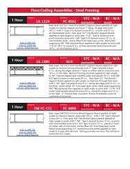
1-hr UL L522 22<br />
1-hr UL L501 22<br />
1-hr UL L515 22<br />
1-hr FM FC-181 22<br />
1-hr FM FC-193 22<br />
1-hr FM FC-172 22<br />
2-hr UL L505 22<br />
<strong>Gypsum</strong> Board Floor/Ceiling –<br />
Wood Framing (floor truss)<br />
Fire Rating Design No. Page<br />
1-hr UL L558 23<br />
1-hr FM FC-442 23<br />
1-hr UL L528 23<br />
1-hr FM FC-448 23<br />
1-hr FM FC-214 23<br />
2-hr UL L538 23<br />
<strong>Gypsum</strong> Board Roof/Ceiling –<br />
Wood Framing (pitched roof truss)<br />
Fire Rating Design No. Page<br />
1-hr UL P533 23<br />
10 NATIONAL GYPSUM QUICK SELECTOR/GENERAL REFERENCE<br />
<strong>Gypsum</strong> Board Floor/Ceiling –<br />
Light Gauge Steel Framing<br />
Fire Rating Design No. Page<br />
1-hr UL L524 24<br />
1 1⁄2-hr UL L527 24<br />
1-hr UL L565 24<br />
<strong>Gypsum</strong> Board Floor/Ceiling –<br />
Steel Framing (steel joists with<br />
concrete floor)<br />
Fire Rating Design No. Page<br />
1-hr OSU T-1936 24<br />
1-hr FM FC-134 25<br />
2-hr UL G503 24<br />
2-hr UL G514 25<br />
3-hr UL G512 25<br />
2-hr FM FC-134 25<br />
2-hr UL G523 25<br />
2-hr UL D502 25<br />
2-hr UL G222 25<br />
2-hr FM FC-299 25<br />
1 1⁄2-hr UL G259 25<br />
1 1⁄2- hr FM FC-300 25<br />
<strong>Gypsum</strong> Board Roof/Ceiling –<br />
Light Gauge Steel Framing<br />
(pitched roof truss)<br />
Fire Rating Design No. Page<br />
1-hr UL P540 26<br />
1-hr UL P541 26<br />
2-hr UL P543 26<br />
<strong>Gypsum</strong> Board Roof/Ceiling –<br />
Steel Framing (steel joists)<br />
Fire Rating Design No. Page<br />
1-hr FM RC-227 26<br />
<strong>Gypsum</strong> Board Horizontal Shaftwall<br />
Duct Protection<br />
Fire Rating Design No. Page<br />
2-hr WHI 694-0300.1 26
QUICK SELECTOR FOR FIRE AND<br />
SOUND RATED SYSTEMS<br />
NOTES FOR USE OF QUICK SELECTOR<br />
The construction systems shown here are representative of the<br />
many <strong>National</strong> <strong>Gypsum</strong> Drywall partitions and ceilings<br />
systems using Gold Bond BRAND products that have been the<br />
subject of controlled laboratory testing or engineering<br />
evaluations. For a given Fire Resistance Rating or Sound<br />
Isolation value, simply scan the appropriate columns. Design<br />
references prefixed by “Based on...” are extrapolations from<br />
test data on similar assemblies.<br />
In the drawings, in steel or wood stud partitions where insulation<br />
is shown in half of the partition cavity, the insulation is<br />
required for sound ratings only. Where shown across full<br />
cavity, insulation is required for fire rating. Size of studs are<br />
minimum and spacing of studs are maximum for fire rating.<br />
Steel studs are 25 gauge if not specified.<br />
In the following Quick Selector, Underwriters Laboratories, Inc.<br />
Design Numbers refer to designs contained in the UL Fire<br />
Resistance Directory. <strong>National</strong> <strong>Gypsum</strong> Company, Gold Bond<br />
BRAND Fire-Shield and Fire-Shield C products bear the UL<br />
Classification Mark and are covered by UL’s Classification<br />
and Follow-Up Service.<br />
In the following listings, 5/8" Fire-Shield C <strong>Gypsum</strong> Board may<br />
be substituted for 5/8" Fire-Shield in all designs listed for 5/8"<br />
Fire-Shield. 5/8" Fire-Shield C must be used in designs listed<br />
for 5/8" Fire-Shield C.<br />
Descriptions in the Quick Selector tables are summaries. For<br />
copies of tests and/or for detailed information, consult your<br />
<strong>National</strong> <strong>Gypsum</strong> Field Representative (reference inside back<br />
cover).<br />
GYPSUM BOARD CORE UL DESIGNATIONS<br />
KEY TO ABBREVIATIONS:<br />
UL – Underwriters Laboratories, Inc.<br />
OSU – Building Research Laboratories<br />
The Ohio State University<br />
FM – Factory Mutual Research Corporation<br />
GA – <strong>Gypsum</strong> Association<br />
OC – Owens-Corning Fiberglas Corp.<br />
(Tests by Geiger & Hamme)<br />
BBN – Bolt Beranek & Newman<br />
TL – Indicates tests for <strong>National</strong> <strong>Gypsum</strong> Company<br />
by Riverbank Acoustical Laboratories<br />
NGC – <strong>National</strong> <strong>Gypsum</strong> Company<br />
WHI – Warnock-Hersey International, Inc.<br />
U. of Cal. – University of California<br />
PFS – PFS Corporation<br />
NBS – <strong>National</strong> Bureau of Standards<br />
BMS – Building Materials and Structures<br />
ITS – Intertek Testing Services<br />
GENERAL REFERENCE<br />
1/2" (12.7 mm) Fire-Shield C: FSW-C<br />
1/2" (12.7 mm) XP Fire-Shield C: FSMR-C<br />
5/8" (15.9 mm) Fire-Shield: FSW<br />
5/8" (15.9 mm) XP Fire-Shield: FSW-3<br />
5/8" (15.9 mm) Fire-Shield C: FSW-C<br />
1/2" (12.7 mm) Fire-Shield C Kal-Kore: FSK-C<br />
5/8" (15.9 mm) Fire-Shield Kal-Kore: FSK<br />
5/8" (15.9 mm) Hi-Abuse XP Fire-Shield: FSW<br />
5/8" (15.9 mm) Hi-Impact XP Fire-Shield: FSW-5<br />
5/8" (15.9 mm) Fire-Shield Exterior Soffit Board: FSW<br />
5/8" (15.9 mm) Fire-Shield Jumbo Sheathing: FSW-3<br />
5/8" (15.9 mm) Fire-Shield e 2 XP: FSW-6<br />
1" (25.4 mm) Fire-Shield Shaftliner: FSW<br />
1" (25.4 mm) Fire-Shield Shaftliner XP: FSW<br />
QUICK SELECTOR FOR FIRE AND SOUND RATED SYSTEMS<br />
<strong>Gypsum</strong> Plaster Partitions - Metal Lath (CAD FILE NAME GOLDA.DWG OR GOLDA.DXF)<br />
No. Fire Rating Ref. Design No. Description STC Test No.<br />
1 1 hr. OSU T-147 1 1/2" (38.1 mm) gypsum plaster, 100:2 1/2 perlite<br />
(scratch and brown coats), on metal lath attached to<br />
3/4" (19.0 mm) channel studs at 16" o.c. (406 mm).<br />
None None<br />
2 1 hr. OSU T-129 2" (51 mm) gypsum plaster, 1:2 sand, on 3.4 diamond 37 NBS 171A<br />
mesh lath attached to 3/4" (19.0 mm) channel studs at<br />
16" o.c. (406 mm).<br />
3 2 hr. UL U413 2 1/2" (63.5 mm) gypsum plaster, 100:2 perlite, on 3.4 diamond 33 Est.<br />
mesh lath attached to 3/4" (19.0 mm) channel studs at 16" o.c.<br />
(406 mm).<br />
4 2 hr. NBS 2 1/2" (63.5 mm) gypsum plaster, 100:2 vermiculite scratch None None<br />
coat, 100:3 vermiculite brown coat on metal lath attached to<br />
3/4" (19.0 mm) channel studs at 16" o.c. (406 mm).<br />
*The fire resistance of the above assemblies was determined with one plane of metal lath. The assemblies with two planes of metal lath may be considered to have<br />
equivalent fire-resistant ratings.<br />
NATIONAL GYPSUM QUICK SELECTOR/GENERAL REFERENCE<br />
11<br />
QUICK<br />
SELECTOR
QUICK SELECTOR FOR FIRE AND SOUND RATED SYSTEMS<br />
<strong>Gypsum</strong> Plaster Fireproofing Columns (10WF49 or heavier) (CAD FILE NAME GOLDB.DWG OR GOLDB.DXF)<br />
No. Fire Rating<br />
FIRE – SOUND<br />
Ref. Design No. Description STC Test No.<br />
1 1 hr. BMS 92-Table 40 3/4" (19.0 mm) gypsum plaster, 1:3 sand scratch, 1:3 None None<br />
GA CM 1300 sand brown on metal lath.<br />
2 2 hr. UL X402 1" (25.4 mm) gypsum plaster, 100:2 perlite scratch, None None<br />
GA CM 2320 100:3 perlite brown, on self-furring lath.<br />
3 3 hr. UL X402 1 3/8" (34.9 mm) gypsum plaster, 100:2 perlite scratch, None None<br />
GA CM 3310 100:3 perlite brown, on self-furring lath.<br />
4 4 hr. UL X402 1 3/4" (44.5 mm) gypsum plaster, 100:2 perlite scratch, None None<br />
GA CM 4410 100:3 perlite brown, on self-furring lath.<br />
<strong>Gypsum</strong> Plaster Fireproofing Beams (8WF24 or heavier) (CAD FILE NAME GOLDC.DWG OR GOLDC.DXF)<br />
1 2 hr. UL R4197-1 1 1/8" (28.6 mm) gypsum plaster, 100:2 1/2 perlite scratch None None<br />
GA BM 2221 coat, 100:2 1/2 perlite brown coat on self-furring lath.<br />
2 3 hr. UL R4197-1 1 1/4" (38.1 mm) gypsum plaster, 100:2 1/2 perlite scratch None None<br />
GA BM 3110 coat, 100:2 1/2 perlite brown coat on self-furring lath.<br />
Veneer Plaster Partitions-Wood Framing (CAD FILE NAME GOLDD.DWG OR GOLDD.DXF)<br />
No. Fire Rating Ref. Design No. Description STC Test No.<br />
1 1 hr. U. of Cal. E.S. 6727 3/32" (2.4 mm) Veneer Plaster applied to 1/2" (12.7 mm)<br />
Fire-Shield C Kal-Kore nailed to both sides of wood studs<br />
16" o.c. (406 mm).<br />
34 NGC 2161<br />
Veneer Plaster Partitions-Steel Framing (CAD FILE NAME GOLDE.DWG OR GOLDE.DXF)<br />
1 1hr. U. of Cal. E.S. 6892 3/32" (2.4 mm) Veneer Plaster applied to 1/2" (12.7 mm) 42 est.<br />
Fire-Shield C Kal-Kore on both sides of 2 1/2" (63.5 mm)<br />
steel studs 24" o.c. (610 mm) with 1" (25.4 mm) screws<br />
12" o.c. (144 mm) and 9" o.c. (229 mm) along edges.<br />
Studs 16" o.c. (406 mm) preferred method.<br />
For additional Kal-Kore Fire and Sound rated systems reference gypsum board systems.<br />
<strong>Gypsum</strong> Board Partitions-Wood Framing (load-bearing) (CAD FILE NAME GOLDH.DWG OR GOLDH.DXF)<br />
No. Fire Rating Ref. Design No. Description STC Test No.<br />
FIRE – SOUND<br />
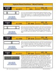
1 45 min. UL U317 1/2" (12.7 mm) Fire-Shield C <strong>Gypsum</strong> Board or 1/2"<br />
(12.7 mm) Fire-Shield C Kal-Kore plaster base nailed both<br />
sides 2 x 4 (38 mm x 89 mm) studs, 16" o.c. (406 mm).<br />
34 NGC 2161<br />
2 1 hr. UL U305 5/8" (15.9 mm) Fire-Shield <strong>Gypsum</strong> Board, 5/8" (15.9 mm) 35 NGC 2403<br />
GA WP 3605 Fire-Shield Kal-Kore plaster base or 5/8" (15.9 mm) Fire-Shield<br />
XP Board nailed both sides 2 x 4 (38 mm x 89 mm)<br />
wood studs, 16" o.c. (406 mm).<br />
12 NATIONAL GYPSUM QUICK SELECTOR/GENERAL REFERENCE
QUICK SELECTOR FOR FIRE AND SOUND RATED SYSTEMS<br />
<strong>Gypsum</strong> Board Partitions-Wood Framing (load-bearing) (cont’d) (CAD FILE NAME GOLDH.DWG OR GOLDH.DXF)<br />
GENERAL REFERENCE<br />
No. Fire Rating<br />
FIRE – SOUND<br />
Ref. Design No. Description STC Test No.<br />
3 1 hr. UL U309 5/8" (15.9 mm) Fire-Shield <strong>Gypsum</strong> Board or 5/8" 38 NGC 2404<br />
GA WP 3510 (15.9 mm) Fire-Shield XP Board nailed both sides<br />
2 x 4 (38 mm x 89 mm) studs, 24" o.c. (610 mm).<br />
4 1 hr. UL U340 5/8" (15.9 mm) Fire-Shield C <strong>Gypsum</strong> Board nailed or 45 Based on<br />
screwed 7" o.c.(178 mm) to 2x4 (51 mm x 102 mm) NGC 2375<br />
wood studs 24" o.c. (610 mm) staggered 12" o.c.<br />
(305 mm). Single 6" (152 mm) plate. Sound rating with<br />
3 1/2" (88.9 mm) glass fiber in cavity.<br />
5 1 hr. WHI 694-0200 5/8" (15.9 mm) Fire-Shield C <strong>Gypsum</strong> Board, screw applied 50 Based on<br />
GA Based on to Resilient Furring Channel spaced 24" o.c. (610 mm) one side TL 77-138<br />
WP 3230 only, on 2 x 4 (38 mm x 89 mm) studs spaced 24" o.c. (610 mm).<br />
Other side 5/8" (15.9 mm) Fire-Shield C <strong>Gypsum</strong> Board screw<br />
attached direct to studs. 3" (76 mm) mineral wool (3 pcf)<br />
in stud cavity.<br />
6 1 hr. UL U312 1/2" (12.7 mm) Fire-Shield C <strong>Gypsum</strong> Board, 1/2" (12.7 mm) 45 NGC 2321<br />
FM WP-147 Fire-Shield C Kal-Kore plaster base or 1/2" (12.7 mm) Fire-Shield<br />
GA WP 3341 C Durasan laminated to 1/4" <strong>Gypsum</strong> Board nailed to both<br />
sides 2 x 4 (38 mm x 89 mm) studs, spaced 16" o.c. (406 mm).<br />
7 2 hr. FM WP-360 5/8" (15.9 mm) Fire-Shield <strong>Gypsum</strong> Board base layer nail 40 Based on<br />
GA WP 4135 applied horizontally to both sides 2 x 4 (38 mm x 89 mm) wood<br />
studs, spaced 24" o.c. (610 mm). Face layer 5/8" (15.9 mm)<br />
Fire-Shield <strong>Gypsum</strong> Board nail applied horizontally to both sides.<br />
NGC 2363<br />
Rating also applies with 5/8" (15.9 mm) Fire-Shield Kal-Kore plaster base.<br />
8 est. FM Based on Two layers 5/8" (15.9 mm) Fire-Shield <strong>Gypsum</strong> Board nailed 50 NGC 2368<br />
2 hr. WP-360 one side to 2 x 4 (38 mm x 89 mm) wood studs, 16" o.c.<br />
GA Based on (406 mm). Two layers other side screw applied to Resilient<br />
WP 4135 Furring Channels spaced 24" o.c. (610 mm). Rating also<br />
applies with 5/8" (15.9 mm) Fire-Shield Kal-Kore plaster base.<br />
9 2 hr. FM Based on Two layers 5/8" (15.9 mm) Fire-Shield <strong>Gypsum</strong> Board nail 51 NGC 2377<br />
WP-360 applied horizontally to both sides of 2 x 4 (38 mm x 89 mm)<br />
GA WP 3910 wood studs 16" o.c. (406 mm) staggered 8" o.c. (203 mm).<br />
Single 6" (152 mm) plate. Rating also applies with 5/8" (15.9 mm)<br />
Fire-Shield Kal-Kore plaster base.<br />
10 2 hr. FM Based on 5/8" (15.9 mm) Fire-Shield <strong>Gypsum</strong> Board base layer applied 58 NGC 3056<br />
WP-360 vertically,nailed 24" o.c. (610 mm). Face layer 5/8" (15.9 mm)<br />
GA WP 3820 Fire-Shield <strong>Gypsum</strong> Board applied horizontally, nailed 8" o.c.<br />
(203 mm). Double row of 2 x 4 (38 mm x 89 mm) wood studs<br />
16" o.c. (406 mm) on separate plates, sound rating with 3 1/2"<br />
(88.9 mm) mineral wool or glass fiber in cavity. Rating also<br />
applies with 5/8" (15.9 mm) Fire-Shield Kal-Kore plaster base.<br />
11 2 hr. UL U301 Two layers of 5/8" (15.9 mm) Fire-Shield <strong>Gypsum</strong> Board<br />
or 5/8" (15.9 mm) Fire-Shield Kal-Kore plaster base nail applied<br />
to 2 x 4 (38 mm x 89 mm) wood studs spaced 16" o.c (406 mm).<br />
40 NGC 2363<br />
Boards may be applied horizontally or vertically with all joints staggered.<br />
EXTERIOR WALLS<br />
12 2 hr. UL U302 Two layers 5/8" (15.9 mm) Fire-Shield <strong>Gypsum</strong> Board<br />
GA WP 8410 nailed horizontally or vertically to inside face of 2 x 4<br />
(38 mm x 89 mm) wood studs 16" o.c. (406 mm).<br />
1/2" (12.7 mm) gypsum sheathing or e2 XP sheathing<br />
nailed to outside face of studs, brick veneer facing.<br />
13 1 hr. UL Based on 5/8" (15.9 mm) Fire-Shield <strong>Gypsum</strong> Board nailed<br />
U309 horizontally or vertically to inside face of 2 x 4<br />
GA WP 8105 (38 mm x 89 mm) wood studs 24" o.c. (406 mm).<br />
5/8" (15.9 mm) Fire-Shield <strong>Gypsum</strong> Sheathing<br />
e2 XP sheathing nailed vertically to outside face of<br />
studs 7" o.c. (178 mm) in field, 4" o.c. (102 mm)<br />
perimeter. Exterior cladding attached through sheathing<br />
into studs.<br />
NATIONAL GYPSUM QUICK SELECTOR/GENERAL REFERENCE<br />
13<br />
QUICK<br />
SELECTOR
QUICK SELECTOR FOR FIRE AND SOUND RATED SYSTEMS<br />
<strong>Gypsum</strong> Board Partitions-Wood Framing (load-bearing) (cont’d) (CAD FILE NAME GOLDH.DWG OR GOLDH.DXF)<br />
No. Fire Rating Ref. Design No. Description STC Test No.<br />
FIRE – SOUND<br />
14 1 hr. WHI 651-0319 5/8" (15.9 mm) Fire-Shield C <strong>Gypsum</strong> Board horizontally nailed<br />
to one side of horizontal 2 x 4 (38 mm x 89 mm) girts spaced<br />
24" o.c. on 6 x 6 wood columns spaced 8'-0" o.c. Metal cladding<br />
vertically screw attached to exterior horizontal girts with 3" thick<br />
mineral fiber insulation nailed to interior of exterior girts.<br />
15 2 hr. UL U371 Two layers 5/8" (15.9 mm) Fire-Shield <strong>Gypsum</strong> Board screw attached horizontally<br />
GA WP 8417 or vertically to inside face of 2 x 4 (38 mm x 89 mm) wood studs spaced<br />
16" o.c. 5/8" (15.9 mm) Fire-Shield <strong>Gypsum</strong> Sheathing or e 2 XP sheathing<br />
nail or screw attached horizontally to outside of studs. Portland Cement Stucco facing.<br />
3" (76 mm) mineral wool in stud cavity.<br />
<strong>Gypsum</strong> Board Partitions-Steel Framing (CAD FILE NAME GOLDJ.DWG OR GOLDJ.DXF)<br />
No. Fire Rating Ref. Design No. Description STC Test No.<br />
1 1 hr. OSU T-3296 5/8" (15.9 mm) Fire-Shield <strong>Gypsum</strong> Board, 5/8" (12.7 mm) 38 NGC 2384<br />
GA WP 1340 Fire-Shield Kal-Kore plaster base, or 5/8" Fire-Shield<br />
XP <strong>Gypsum</strong> Board screw attached vertically to both sides 1 5/8"<br />
(41.3 mm) steel studs, 24" o.c. (610 mm). <strong>Gypsum</strong> board joints<br />
staggered.<br />
2 1 hr. UL U420 Chase wall, 5/8" (15.9 mm) Fire-Shield <strong>Gypsum</strong> Board screw 52 TL 76-155<br />
GA WP 5015 attached vertically to both sides. Air space minimum 4 1/2"<br />
(114.3 mm) between inside gypsum board faces. Sound rating<br />
with 3 1/2" (88.9 mm) mineral wool or glass fiber. 1 5/8"<br />
(41.3 mm) steel studs, 24" o.c., (610 mm) cross braced at third<br />
points with 5/8" (15.9 mm.) <strong>Gypsum</strong> board gussets 9 1/2" x 12"<br />
(241.3 mm x 305 mm) or 9 1/2" (241.3 mm) long stud track.<br />
3 1 hr. OSU Based On 5/8" (15.9 mm) Fire-Shield <strong>Gypsum</strong> Board, 5/8" (12.7 mm) 40 NGC 2438<br />
T-3296 Fire-Shield Kal-Kore plaster base or 5/8" (15.9 mm) Fire-Shield<br />
XP <strong>Gypsum</strong> Board screw attached vertically to both sides 2 1/2"<br />
(63.5 mm) steel studs, 24" o.c. (610 mm). <strong>Gypsum</strong> board joints<br />
staggered.<br />
14 NATIONAL GYPSUM QUICK SELECTOR/GENERAL REFERENCE<br />
GA WP 1340 With 2 1/2" (63.5 mm) of mineral wool or glass fiber in cavity. 45 NGC 2391<br />
4 1 hr. UL V401 1/2" (12.7 mm) Fire-Shield C <strong>Gypsum</strong> Board or 1/2" 45 NGC 2179<br />
UL V438 (12.7 mm) Fire-Shield C Kal-Kore plaster base screw attached<br />
FM WP-51 vertically to both sides 2 1/2" (63.5 mm) steel studs, 24" o.c.<br />
GA WP 1070 (610 mm). 2" (51 mm) mineral wool [2.5 pcf (40 kg/m 3 )]<br />
in stud cavity. <strong>Gypsum</strong> board joints staggered.<br />
1 hr. UL V401 1/2" (12.7 mm) Fire-Shield C <strong>Gypsum</strong> Board or 1/2"<br />
UL V438 (12.7 mm) Fire-Shield C Kal-Kore plaster base screw attached<br />
FM WP-731 horizontally to both sides, 2 1/2" (63.5 mm) steel studs, 24"<br />
GA WP 1071 o.c. (610 mm). 2" (51 mm) mineral wool [3 pcf (48 kg/m 3 )]<br />
in stud cavity. Horizontal joints not staggered with those on<br />
the opposite side of partition.<br />
5 1 hr. UL U451 1/2" (12.7 mm) Fire-Shield C <strong>Gypsum</strong> Board screw applied est. 50<br />
to resilient furring channel spaced 24" o.c. (610 mm) one side<br />
only, on 2 1/2" (63.5 mm) steel studs spaced 24" o.c. (610 mm).<br />
Other side 1/2" (12.7 mm) Fire-Shield C <strong>Gypsum</strong> Board screw<br />
attached direct to studs 3" (76 mm) mineral wool (3pcf) in stud cavity.
QUICK SELECTOR FOR FIRE AND SOUND RATED SYSTEMS<br />
10 1 hr. FM WP-66 1/2" (12.7 mm) Fire-Shield C <strong>Gypsum</strong> Board screw vertically 43 Based on<br />
GA WP 1021 applied to 2 1/2" (63.5 mm) steel stud. Double layer on one side, NGC 2248<br />
single layer on the other. Base layer screw attached, face layer and<br />
single layer screwed at edges, adhesively attached along center.<br />
<strong>Gypsum</strong> board joints staggered.<br />
FM WP-733 2 1/2" (63.5 mm) screw studs, 24" o.c. (610 mm) double layer of<br />
GA WP 1022 1/2" (12.7 mm) Fire-Shield <strong>Gypsum</strong> Board screw applied horizontally<br />
one side with face layer staggered 2' (610 mm) from base layer.<br />
Other side one layer screw applied horizontally. Face layer horizontal<br />
joints each side not staggered.<br />
GENERAL REFERENCE<br />
<strong>Gypsum</strong> Board Partitions-Steel Framing (cont’d) (CAD FILE NAME GOLDJ.DWG OR GOLDJ.DXF)<br />
No. Fire Rating Ref. Design No. Description STC Test No.<br />
FIRE – SOUND<br />
6 1 hr. FM WP 45 5/8" (15.9 mm) Fire-Shield <strong>Gypsum</strong> Board, 5/8" (15.9 mm) 38 NGC<br />
GA WP 1350 Fire-Shield Kal-Kore plaster base or 5/8" (15.9 mm) Fire-Shield<br />
XP <strong>Gypsum</strong> Board screw attached horizontally to both sides 3 5/8"<br />
(92.1 mm) steel studs, 24" o.c. (610 mm). All gypsum board joints<br />
staggered.<br />
2005004<br />
OSU T-1770 5/8" (15.9 mm) Fire-Shield <strong>Gypsum</strong> Board screw attached<br />
vertically to both sides 3 5/8" (92.1 mm) steel studs, 24" o.c.<br />
(610 mm). <strong>Gypsum</strong> board joints staggered.<br />
2386<br />
2 1/2" (63.5 mm) mineral wool or glass fiber in cavity. 47 NGC<br />
UL U465 5/8" (15.9 mm) Fire-Shield <strong>Gypsum</strong> Board, 5/8" (15.9 mm) Fire-Shield<br />
UL V438 Kal-Kore plaster base or 5/8" (15.9 mm) Hi-Impact XP Fire-Shield<br />
GA WP 1081 <strong>Gypsum</strong> Board screw attached vertically with fasteners 8" o.c. (203 mm)<br />
at edges and 12" o.c. (305 mm) in the field of the board to 3 5/8"<br />
(92.1 mm) board to 3 5/8" (92.1 mm) steel studs spaced maximum<br />
24" o.c. (610 mm) with joints staggered on opposite sides of the wall.<br />
7 1 hr. UL V452 1/2" (12.7 mm) PermaBase cement board screw attached 45 NGC<br />
ITS/WHI J99-4001 horizontally or vertically on one side to 3 5/8" steel studs 16" o.c. 2099015<br />
(406 mm) and 5/8" (15.9 mm) Fire-Shield <strong>Gypsum</strong> Board screw<br />
attached vertically on opposite side, joints staggered, 3" (76 mm)<br />
thick mineral wool batts [2.5 pcf (40 kg/m 3 )] in stud cavity.<br />
8 45 min. FM Based on 1/2" (12.7 mm) Fire-Shield C <strong>Gypsum</strong> Board or 1/2" 45 NGC 2146<br />
WP-51 (12.7 mm) Fire-Shield C Kal-Kore plaster base screw attached<br />
vertically to both sides 3 5/8" (92.1 mm) steel studs, 24" o.c.<br />
(610 mm). 2" (51 mm) glass fiber in stud cavity.<br />
<strong>Gypsum</strong> board joints staggered.<br />
9 1 hr. UL Based on 1/2" (12.7 mm) Fire-Shield C <strong>Gypsum</strong> Board or 1/2" 45 NGC 2149<br />
V401 (12.7 mm) Fire-Shield C Kal-Kore plaster base screw<br />
FM Based on attached vertically to both sides 3 5/8" (92.1 mm) steel<br />
WP-51 studs, 24" o.c. (610 mm). 2" (51 mm) mineral wool<br />
GA WP 1070 [2.5 pcf (40 kg/m 3 )] in stud cavity. <strong>Gypsum</strong> board joints staggered.<br />
11 1 hr. FM Based on 1/2" (12.7 mm) Fire-Shield C <strong>Gypsum</strong> Board screw attached 50 NGC 2253<br />
WP-66 vertically to both sides 2 1/2" (63.5 mm) steel studs, spaced 24" o.c.<br />
(610 mm). Second layer screw attached vertically to one side only<br />
GA Based on and 3" (76 mm) glass fiber in cavity. <strong>Gypsum</strong> board joints staggered.<br />
WP 1021<br />
12 1 hr. FM Based on 1/2" (12.7 mm) Fire-Shield C <strong>Gypsum</strong> Board screw attached 44 NGC 2323<br />
WP-66 vertically to both sides 3 5/8" (92.1 mm) steel studs, spaced 24"<br />
o.c. (610 mm). Second layer screw attached vertically to one side<br />
only. <strong>Gypsum</strong> board joints staggered.<br />
GA Based on 3" (76 mm) glass fiber cavity. 50 Based on<br />
WP 1021 NGC 2253<br />
NATIONAL GYPSUM QUICK SELECTOR/GENERAL REFERENCE<br />
15<br />
QUICK<br />
SELECTOR
QUICK SELECTOR FOR FIRE AND SOUND RATED SYSTEMS<br />
<strong>Gypsum</strong> Board Partitions-Steel Framing (cont’d) (CAD FILE NAME GOLDJ.DWG OR GOLDJ.DXF)<br />
No. Fire Rating Ref. Design No. Description STC Test No.<br />
FIRE – SOUND<br />
13 1 hr. UL U410 1/2" (12.7 mm) Fire-Shield C <strong>Gypsum</strong> Board, 1/2" (12.7 mm) 45 NGC 2328<br />
FM WP-152 Fire-Shield C Kal-Kore plaster base or 1/2" (12.7 mm) Fire-<br />
GA WP 1051 Shield Durasan laminated to 1/4" (6.35 mm) <strong>Gypsum</strong> Board<br />
screw attached both sides 2 1/2" (63.5 mm) steel studs,<br />
24" o.c. (610 mm). <strong>Gypsum</strong> board joints staggered. 2" 53 NGC 2318<br />
(51 mm) mineral wool or glass fiber in cavity.<br />
14 1 1/2 hr. OSU T-3240 5/8" (15.9 mm) Fire-Shield <strong>Gypsum</strong> Board or 5/8" (15.9 mm) 44 NGC 2388<br />
Fire-Shield XP Board screw attached vertically to both sides 3 5/8"<br />
(92.1 mm) steel studs, 24" o.c. (610 mm). Second layer one side<br />
only, laminated vertically. <strong>Gypsum</strong> board joints staggered.<br />
15 2 hr. UL V449 5/8" (15.9 mm) Fire-Shield <strong>Gypsum</strong> Board screw attached<br />
GA WP 1943 vertically to both sides 3 1/2" (88.9 mm) steel studs, spaced<br />
24" o.c. (610 mm) Triple layer one side, single layer on the other.<br />
<strong>Gypsum</strong> board joints staggered.<br />
16 2 hr. UL V438 Two layers 1/2" (12.7 mm) Fire-Shield C <strong>Gypsum</strong> Board 45 est.<br />
screw attached both sides 1 5/8" (41.3 mm) steel studs 24" o.c.<br />
(610 mm). Base layers applied vertically, face layers applied<br />
vertically or horizontally. Vertical joints staggered.<br />
17 2 hr. UL U420 Chase wall. Two layers 5/8" (15.9 mm) Fire-Shield <strong>Gypsum</strong> 57 TL-76-156<br />
GA WP 5105 Board screw attached vertically to 1 5/8" (41.3 mm) steel studs,<br />
24" o.c. (610 mm). Air space minimum 4 1/2" (114.3 mm).<br />
Sound rating with 3 1/2" (88.9 mm) mineral wool or glass fiber.<br />
1 5/8" (41.3 mm) steel studs, 24" o.c., (610 mm) cross braced<br />
at third points with 5/8” (15.9 mm) <strong>Gypsum</strong> board gussets 9 1/2" x 12"<br />
9 1/2" x 12" (241.3 mm x 305 mm) or 9 1/2" (241.3 mm) long stud track.<br />
18 2 hr. UL U412 Two layers 1/2" (12.7 mm) Fire-Shield C <strong>Gypsum</strong> Board or 46 NGC 2250<br />
FM WP-635 1/2" (12.7 mm) XP Fire-Shield <strong>Gypsum</strong> Board screw attached<br />
GA Based on both sides 2 1/2" (63.5 mm) steel studs, spaced 24" o.c. (610 mm).<br />
WP 1615 Base layers vertical, face layers horizontal. All vertical joints staggered.<br />
U. of Cal. UC9-7-64 3" (76 mm) glass fiber in cavity. 53 NGC 2252<br />
GA Based on<br />
WP 1545<br />
19 2 hr. UL U411 Base layer 5/8" (15.9 mm) Fire-Shield <strong>Gypsum</strong> Board 55 NGC 2382<br />
GA Based on screw attached vertically both sides to 2 1/2" (63.5 mm) steel<br />
WP 1711 studs 24" o.c. (610 mm). Face layer laminated or screw<br />
attached vertically both sides. 2 1/2" (63.5 mm) mineral wool<br />
or glass fiber in cavity. <strong>Gypsum</strong> board joints staggered.<br />
WHI 495-0236 Two layers 5/8" (15.9 mm) Fire-Shield <strong>Gypsum</strong> Board 56 NGC 3022<br />
GA WP 1548 screw attached horizontally with vertical and horizontal joints<br />
staggered and 3" (76 mm) mineral wool or glass fiber in cavity.<br />
20 2 hr. UL V438 Two layers 5/8" (15.9 mm) Fire-Shield <strong>Gypsum</strong> Board<br />
or 5/8" (15.9 mm) Hi-Impact XP Fire-Shield <strong>Gypsum</strong> Board base<br />
layer screw attached vertically to both sides 2 1/2" (63.5 mm)<br />
steel studs 24" o.c. (610 mm). Vertical joints staggered.<br />
21 2 hr. UL U412 Two layers 1/2" (12.7 mm) Fire-Shield C <strong>Gypsum</strong> Board or 48 NGC 2282<br />
FM Based on 1/2" (12.7 mm) XP Fire-Shield <strong>Gypsum</strong> Board screw attached<br />
WP-635 both sides 3 5/8" (92.1 mm) steel studs, spaced 24" o.c. (610 mm).<br />
Base layers vertical, face layers horizontal. All vertical joints staggered.<br />
16 NATIONAL GYPSUM QUICK SELECTOR/GENERAL REFERENCE<br />
GA Based on<br />
WP 1630 3" (76 mm) mineral wool or glass fiber in cavity. 53 NGC 2288
QUICK SELECTOR FOR FIRE AND SOUND RATED SYSTEMS<br />
GENERAL REFERENCE<br />
<strong>Gypsum</strong> Board Partitions-Steel Framing (cont’d) (CAD FILE NAME GOLDJ.DWG OR GOLDJ.DXF)<br />
No. Fire Rating Ref. Design No. Description STC Test No.<br />
FIRE – SOUND<br />
22 2 hr. OSU T-1771 First layer 5/8" (15.9 mm) Fire-Shield <strong>Gypsum</strong> Board 48 NGC 2282<br />
GA Based on screw attached vertically both sides 3 5/8" (92.1 mm) steel<br />
WP 1711 studs, spaced 24" o.c. (610 mm). Second layer laminated<br />
vertically both sides. Vertical joints staggered.<br />
23 2 hr. UL U411 First layer 5/8" (15.9 mm) Fire-Shield <strong>Gypsum</strong> Board 56 NGC 3022<br />
GA WP 1616 screw attached vertically both sides 3 5/8" (92.1 mm) steel<br />
studs, spaced 24" o.c. (610 mm). Second layer laminated or<br />
screw attached vertically both sides and 3" (76 mm) mineral<br />
wool or glass fiber in cavity. Vertical joints staggered.<br />
24 2 hr. UL V452 1/2" (12.7 mm) PermaBase cement board face layer screw 52 NGC<br />
ITS/WHI J98-32931 attached vertically over 1/2" (12.7 mm) Fire-Shield C <strong>Gypsum</strong> 2099016<br />
Board base layer on one side to 3 5/8" steel studs 16" o.c.<br />
(406 mm) and double layer of 1/2" (12.7 mm) Fire-Shield C<br />
<strong>Gypsum</strong> Board applied vertically to opposite side with 3"<br />
(76 mm) thick mineral wool insulation batts [2.5 pcf (40 kg/m 3 )]<br />
in stud cavity. All joints staggered between face and base layers.<br />
25 3 hr. UL U435 Three layers of 1/2" (12.7 mm) Fire-Shield C <strong>Gypsum</strong> Board 48 NGC 2631<br />
WHI 694-0084 screw attached to each side of 1 5/8" (41.3 mm) steel studs,<br />
GA WP 2921 24" o.c. (610 mm). Base and second layer vertical, face layer<br />
horizontal. All gypsum board joints staggered.<br />
1 1/2" (38.1 mm) mineral wool or glass fiber in cavity. 53 NGC 2636<br />
26 3 hr. UL V438 Three layers of 5/8" (15.9 mm) Fire-Shield <strong>Gypsum</strong> Board 48 Based on<br />
screw attached to each side of 1 5/8" (41.3 mm) steel studs, NGC 2631<br />
24" o.c. (610 mm). Base and second layer vertical, face layer<br />
vertical or horizontal. All gypsum board joints staggered.<br />
1 1/2" (38.1 mm) mineral wool or glass fiber in cavity. 53<br />
NATIONAL GYPSUM QUICK SELECTOR/GENERAL REFERENCE<br />
Based on<br />
NGC 2633<br />
27 4 hr. UL U435 Four layers of 1/2" (12.7 mm) Fire-Shield C <strong>Gypsum</strong> Board 51 NGC 2633<br />
WHI 694-108.1 screw attached to each side of 1 5/8" (41.3 mm) steel studs,<br />
GA WP 2970 24" o.c. (610 mm). Base, second and third layer vertical, face<br />
layer horizontal. All gypsum board joints staggered except long<br />
joints of base and second layer fall on the same studs.<br />
GA WP 2960 1 1/2" (38.1 mm) mineral wool or glass fiber in cavity. 55 NGC 2634<br />
28 4 hr. UL V438 Four layers of 5/8" (15.9 mm) Fire-Shield <strong>Gypsum</strong> Board 51<br />
screw attached to each side of 1 5/8" (41.3 mm) steel studs,<br />
24" o.c. (610 mm). Base, second and third layer vertical, face<br />
layer vertical or horizontal. All gypsum board joints staggered.<br />
1 1/2" (38.1 mm) mineral wool or glass fiber in cavity. 55<br />
Based on<br />
NGC 2633<br />
Based on<br />
NGC 2633<br />
17<br />
QUICK<br />
SELECTOR
QUICK SELECTOR FOR FIRE AND SOUND RATED SYSTEMS<br />
<strong>Gypsum</strong> Board Partitions-Steel Framing (load-bearing) (CAD FILE NAME GOLDJ.DWG OR GOLDJ.DXF)<br />
No. Fire Rating Ref. Design No. Description STC Test No.<br />
FIRE – SOUND<br />
1 1 hr. UL U425 One layer 5/8" (15.9 mm) Fire-Shield <strong>Gypsum</strong> Board<br />
GA WP 1206 screw applied vertically to each side of 3 1/2" (88.9 mm)<br />
20 gauge steel studs spaced 24" o.c. (610 mm), studs<br />
laterally braced and fastened to tracks. All gypsum board<br />
joints staggered on opposite sides.<br />
2 2 hr. FM WP-199 Two layers 5/8" (15.9 mm) Fire-Shield <strong>Gypsum</strong> Board screw 40 est.<br />
GA WP 1714 applied vertically to each side of 18 gauge 2 1/2" (63.5 mm)<br />
steel studs spaced 16" o.c. (406 mm). Base layer joints staggered<br />
16" (406 mm) from joints of base layer. Steel bridging required.<br />
3 2 hr. UL U425 Two layers 5/8" (15.9 mm) Fire-Shield <strong>Gypsum</strong> Board<br />
GA WP 1716 screw attached vertically to each side of 3 1/2" (88.9 mm)<br />
20 gauge steel studs spaced 24" o.c. (610 mm), studs laterally<br />
braced and fastened to tracks. All gypsum board joints staggered<br />
on opposite sides. (Tested at 80 percent of design load.)<br />
4 3 hr. UL U426 Four layers of 1/2" (12.7 mm) Fire-Shield C <strong>Gypsum</strong><br />
Board screw attached to each side of 3 1/2" (88.9 mm)<br />
20 gauge steel studs spaced 24" o.c. (610 mm), studs<br />
laterally braced and fastened to tracks. Base, second and<br />
third layers applied vertical; face layer may be applied either<br />
horizontal or vertical. All gypsum board joints staggered<br />
from joints in adjacent layers and on opposite sides of studs.<br />
<strong>Gypsum</strong> Board Partitions/Durasan Prefinished <strong>Gypsum</strong> Board (CAD FILE NAME GOLDK.DWG OR GOLDK.DXF)<br />
No. Fire Rating Ref. Design No. Description STC Test No.<br />
1 1 hr. FM WP-109 30" (762.0 mm) wide 5/8" (15.9 mm) Fire-Shield Durasan applied 44 NGC 2218<br />
GA WP 6130 vertically to 2 1/2" (63.4 mm) steel studs 30" o.c. (762 mm) with steel<br />
batten retainers attached to each stud with 1 1/4" (31.8 mm) Type S<br />
screws spaced 9" o.c. (229 mm). Attach battens over retainers.<br />
2" (51 mm) glass fiber in cavity.<br />
UL U405 48" (1219 mm) wide 5/8" (15.9 mm) Fire-Shield Durasan applied 41 G&H NG-<br />
GA WP 6040 vertically to 2 1/2" (63.5 mm) steel studs 24" o.c. (610 mm) with steel<br />
batten retainers attached to each stud with 1 1/4" (31.8 mm) Type S<br />
screws spaced 9" o.c. (229 mm). Stagger joints on opposite sides<br />
24" o.c. (610 mm). Attach battens over retainers.<br />
145FT<br />
2 2 hr. UL U411 5/8" (15.9 mm) Fire-Shield Durasan laminated vertically with joint 56 NGC 3022<br />
GA WP 1711 compound over base layer 5/8" (15.9 mm) Fire-Shield <strong>Gypsum</strong><br />
Board attached to 3 5/8" (92.1 mm) steel studs 24" o.c. (610 mm).<br />
Face layer laminated with 3/8" (9.5 mm) beads of joint compound 2" o.c.<br />
(51 mm). Face layer secured across top and bottom with 1 5/8"<br />
(41.3 mm) Type S screws 12" o.c. (305 mm). Joints of outer layer<br />
offset 12" (305 mm) from base layer joints. 3" (76 mm) glass fiber<br />
or mineral wool in cavity.<br />
18 NATIONAL GYPSUM QUICK SELECTOR/GENERAL REFERENCE
<strong>Gypsum</strong> Board Partitions/Solid (CAD FILE NAME GOLDL.DWG OR GOLDL.DXF)<br />
GENERAL REFERENCE<br />
No. Fire Rating Ref. Design No. Description STC Test No.<br />
1 1 hr. FM WP-671 1" (25.4 mm) Fire-Shield Shaftliner with 1/2" (12.7 mm) regular 34 Based on<br />
GA WP 1311 <strong>Gypsum</strong> Board laminated vertically with Sta-Smooth joint NGC 2359<br />
compound, both sides.<br />
2 2 hr. UL U525 1" (25.4 mm) Fire-Shield Shaftliner with 1/2" (12.7 mm) 34 Based on<br />
FM WP-668 Fire-Shield C <strong>Gypsum</strong> Board laminated vertically with NGC 2359<br />
GA WP 1841 Sta-Smooth joint compound, both sides.<br />
3 2 hr. UL U505 1" (25.4 mm) Fire-Shield Shaftliner with 5/8" (15.9 mm)<br />
GA WP 7210 Fire-Shield <strong>Gypsum</strong> Board laminated vertically with<br />
Sta-Smooth joint compound, both sides.<br />
4 2 hr. UL U529 1" (25.4 mm) Fire-Shield Shaftliner with 1/2" (12.7 mm)<br />
Fire-Shield C <strong>Gypsum</strong> Board laminated vertically with<br />
Sta-Smooth joint compound, both sides.<br />
QUICK SELECTOR FOR FIRE AND SOUND RATED SYSTEMS<br />
<strong>Gypsum</strong> Board Partitions-Shaftwalls, Area Separation Walls (CAD FILE NAME GOLDM.DWG OR GOLDM.DXF)<br />
No. Fire Rating Ref. Design No. Description STC Test No.<br />
FIRE – SOUND<br />
1 1 hr. UL<br />
FM<br />
GA<br />
U499<br />
WP-755<br />
WP 6905<br />
2 1/2" (63.5 mm), 4" (102 mm) or 6" (152 mm) I-Studs,<br />
C-T Studs or C-H Studs 24" o.c. (610 mm). 1" (25.4 mm)<br />
Fire-Shield Shaftliner or 1" Fire-Shield Shaftliner XP, one<br />
layer of 5/8" (15.9 mm) Fire-Shield <strong>Gypsum</strong> Board applied<br />
horizontally or vertically on side opposite shaftliner. Fire tested both sides.<br />
37 NGC<br />
2001003<br />
1 1/2" (38.1 mm) mineral wool or glass fiber in cavity. 42 NGC 2542<br />
2 2 hr. UL U498 2 1/2" (63.5 mm), 4" (102 mm) or 6" (152 mm) I-Studs, 40 NGC 2618<br />
FM WP-545 C-T Studs or C-H Studs 24" o.c (610 mm). 1" (25.4 mm)<br />
GA WP 7079 Fire-Shield Shaftliner or 1" Fire-Shield Shaftliner XP, and<br />
1 layer of 1/2" (12.7 mm) Fire-Shield C <strong>Gypsum</strong> Board, 1/2"<br />
GA ASW 1215 (12.7 mm) Fire-Shield C Kal-Kore veneer plaster base, or 1/2"<br />
(12.7 mm) Fire-Shield C XP <strong>Gypsum</strong> Board applied horizontally<br />
on each side. Horizontal and vertical joints staggered. Fire tested both sides.<br />
both sides.<br />
1 1/2" (38.1 mm) mineral wool or glass fiber in cavity. 45 NGC 2617<br />
U. of Cal. 75-19 5/8" (15.9 mm) Fire-Shield <strong>Gypsum</strong> Board as face layers. 40 Based on<br />
ES 7407 NGC 2618<br />
GA WP 7077<br />
3 2 hr. UL U429 2 1/2" (63.5 mm), 4" (102 mm) or 6" (152 mm) C-T Studs 40 Based on<br />
GA WP 7084 or C-H Studs 24" o.c. (610 mm), 1" (25.4 mm), NGC 2618<br />
Fire-Shield Shaftliner or 1" Fire-Shield Shaftliner XP and<br />
1 layer of 1/2" (12.7 mm) Fire-Shield C <strong>Gypsum</strong> Board applied<br />
vertically on each side. Joints staggered 24" on opposite sides.<br />
1 1/2" (38.1 mm) mineral wool or glass fiber in cavity. 45<br />
NATIONAL GYPSUM QUICK SELECTOR/GENERAL REFERENCE<br />
Based on<br />
NGC 2617<br />
4 2 hr. UL<br />
FM<br />
GA<br />
U497<br />
WP-636<br />
WP 7080<br />
2 1/2" (63.5 mm), 4" (102 mm) or 6" (152 mm) I-Studs, C-T<br />
Studs or C-H Studs 24" o.c. (610 mm). 1" (25.4 mm) Fire-Shield<br />
Shaftliner or 1" Fire-Shield Shaftliner XP and 2 layers of 1/2" (12.7 mm)<br />
Fire-Shield C <strong>Gypsum</strong> Board, 1/2" (12.7 mm) Fire-Shield C Kal-Kore<br />
veneer plaster base, or 1/2" (12.7 mm) Fire-Shield C XP <strong>Gypsum</strong> Board<br />
on corridor side only, base layer horizontal, face layer vertical.<br />
Fire tested both sides.<br />
40 NGC 2615<br />
1 1/2" (38.1 mm) mineral wool or glass fiber in cavity. 47 NGC 2616<br />
UL<br />
WHI<br />
U497<br />
651-0500.05<br />
2 1/2" (63.5 mm), 4" (102 mm) or 6" (152 mm) I-Studs,<br />
C-T Studs or C-H Studs 24" o.c. (610 mm). 1" (25.4 mm) Fire-<br />
Shield Shaftliner or 1" Fire-Shield Shaftliner XP and two layers<br />
1/2" (12.7 mm) Fire-Shield C <strong>Gypsum</strong> Board applied<br />
horizontally on corridor side. Fire tested both sides.<br />
40 Based on<br />
NGC 2615<br />
U. of Cal. 75-17 2 layers 5/8" (15.9 mm) Fire-Shield <strong>Gypsum</strong> Board on corridor side. 40 Based on<br />
ES 7408 NGC 2615<br />
GA WP 7076<br />
19<br />
QUICK<br />
SELECTOR
QUICK SELECTOR FOR FIRE AND SOUND RATED SYSTEMS<br />
<strong>Gypsum</strong> Board Partitions-Shaftwalls, Area Separation Walls (CAD FILE NAME GOLDM.DWG OR GOLDM.DXF)<br />
No. Fire Rating Ref. Design No. Description STC Test No.<br />
FIRE – SOUND<br />
5 2 hr. UL U428 2 1/2" (63.5 mm), 4" (102 mm) or 6" (152 mm) C-T Studs 40 Based on<br />
GA WP 7051 or C-H Studs 24" o.c. (610 mm). 1" (25.4 mm) NGC 2615<br />
Fire-Shield Shaftliner or 1" Fire-Shield Shaftliner XP<br />
and 2 layers of 1/2" (12.7 mm) Fire-Shield C <strong>Gypsum</strong><br />
6 2 hr. FM WP-621 Elevator Control Boxes, 4" (102 mm) or 6" (152 mm) I-Studs None None<br />
FM WP-612 24" o.c. (610 mm). 1" (25.4 mm) Fire-Shield Shaftliner or 1"<br />
Fire-Shield Shaftliner XP and two layers 1/2" (12.7 mm)<br />
Fire-Shield C <strong>Gypsum</strong> Board on side only, base layer horizontal,<br />
face layer vertical. Control boxes corridor and conduit penetrations.<br />
7 est. FM Based on 2 1/2" (63.5 mm), 4" (102 mm) or 6" (152 mm) I-Studs, C-T 51 BBN<br />
2 hr. WP-636 Studs or C-H Studs 24" o.c. (610 mm). 1" (25.4 mm) Fire-Shield NGC 2609<br />
<strong>Gypsum</strong> Shaftliner, or 1" Fire-Shield Shaftliner XP, Resilient Furring<br />
Channels 24" o.c. (610 mm) on corridor side and two layers 1/2"<br />
(12.7 mm) Fire-Shield C <strong>Gypsum</strong> Board on channels, 1 1/2"<br />
(38.1 mm) mineral wool or glass fiber in stud cavity.<br />
11 2 hr. WHI 651-0508 2 layers of 1" (25.4 mm) Fire-Shield Shaftliner or 1" Fire-Shield<br />
Shaftliner XP inserted in 2" H-Stud 24" o.c. (610 mm). One nominal<br />
2 x 4 (38 mm x 89 mm) wood stud wall one side. 1" (25.4 mm)<br />
air space between Shaftliner and wood studs. Wood studs 16" o.c.,<br />
(406 mm) faced with one layer 1/2" Regular <strong>Gypsum</strong> Board.<br />
50 NGC 2826<br />
3 1/2" (88.9 mm) mineral wool or glass fiber in wood stud cavity. 55 NGC 2825<br />
12 2 hr. UL<br />
GA<br />
U347<br />
ASW 1005<br />
2 layers of 1" (25.4 mm) Fire-Shield Shaftliner or 1" Fire-Shield<br />
Shaftliner XP inserted in 2" H-Stud 24" o.c. (610 mm). Adjacent<br />
construction each side. Minimum 3/4" (19.0 mm) air space between<br />
Shaftliner and adjacent construction.<br />
50 NGC 2823<br />
3 1/2" (88.9 mm) mineral wool or glass fiber in both wood stud cavities. 61 TL 05-199<br />
3 1/2" (88.9 mm) mineral wool or glass fiber in wood stud cavity one side. 55 NGC 2824<br />
20 NATIONAL GYPSUM QUICK SELECTOR/GENERAL REFERENCE<br />
Board, base layer horizontal, face layer vertical.<br />
1 1/2" (38.1 mm) mineral wool or glass fiber in cavity. 47<br />
Based on<br />
NGC 2616<br />
8 2 hr. FM Based on 2 1/2" (63.5 mm), 4" (102 mm) or 6" (152 mm) I-Studs, 50 BBN<br />
WP-545 C-T Studs or C-H Studs 24" o.c. (610 mm). 1" (25.4 mm) NGC 2610<br />
Fire-Shield Shaftliner or 1" Fire-Shield Shaftliner XP and 1<br />
layer of 1/2" (12.7 mm) Fire-Shield C <strong>Gypsum</strong> Board or 1/2"<br />
(12.7 mm) Fire-Shield C XP <strong>Gypsum</strong> Board on one side. Other<br />
side 1 layer 1/2" (12.7 mm) Fire-Shield C <strong>Gypsum</strong> Board<br />
screwed to Resilient Furring Channels 24" o.c. (610 mm) attached<br />
to I-Studs with screws in alternate legs. 1 1/2" (38.1 mm) mineral<br />
wool or glass fiber in cavity.<br />
9 4 hr. UL V451 4" (102 mm) I-Studs, C-T Studs or C-H Studs 24" o.c. (610 mm)<br />
GA WP 7691 1" (25.4 mm) Fire-Shield Shaftliner or 1" Fire-Shield Shaftliner XP<br />
and five layers of 5/8" (15.9 mm) Fire-Shield C <strong>Gypsum</strong> Board<br />
applied vertically to corridor side. Furring channel applied horizontally<br />
16" o.c. (406 mm) over third layer. Vertical joints staggered.<br />
10 2 hr. WHI 694-0200.6 2 layers of 1" (25.4 mm) Fire-Shield Shaftliner or 1" Fire-Shield 35 NGC 2827<br />
Shaftliner XP inserted in 2" H-Stud 24" o.c. (610 mm). H-Studs and<br />
Track covered by 1/2" (12.7 mm) Fire-Shield C <strong>Gypsum</strong> Board<br />
6" (152 mm) wide strips.
QUICK SELECTOR FOR FIRE AND SOUND RATED SYSTEMS<br />
<strong>Gypsum</strong> Board Column Fireproofing (CAD FILE NAME GOLDN.DWG OR GOLDN.DXF)<br />
No. Fire Rating<br />
LIGHT COLUMN<br />
Ref. Design No. Description<br />
1 1 hr. UL X528 Two layers of 1/2" (12.7 mm) Fire-Shield C <strong>Gypsum</strong> Board furred from<br />
GA CM 1452 TS 4x4x0.188 tube steel column by 1 5/8" (43.3 mm) steel stud each corner.<br />
2 1 hr. UL X528 One layer of 5/8" (15.9 mm) Fire-Shield <strong>Gypsum</strong> Board furred from<br />
GA CM 1851 TS 8x8x0.250 tube steel column by 1 5/8" (43.3 mm) steel stud each corner.<br />
3 1 1/2 hr. UL X531 Two layers of 1/2" (12.7 mm) Fire-Shield C <strong>Gypsum</strong> Board furred from<br />
4 1/2" OD steel pipe column (Min. wall thickness 0.109) by 1 5/8" (43.3 mm)<br />
steel framing.<br />
4 2 hr. UL X528 Base and second layer 1/2" (12.7 mm) Fire-Shield C <strong>Gypsum</strong> Board furred from<br />
GA CM 2452 TS 4x4x0.188 tube steel column by 1 5/8" (43.3 mm) steel stud each corner.<br />
Face layer 5/8" (15.9 mm) Fire-Shield <strong>Gypsum</strong> Board.<br />
GENERAL REFERENCE<br />
COLUMN (10WF–49)<br />
5 1 hr. UL X528 One layer of 1/2" (12.7 mm) Fire-Shield C <strong>Gypsum</strong> Board furred from column by 1 5/8"<br />
GA CM 1001 by 1 5/8" (41.3 mm) steel studs at each corner.<br />
6 2 hr. UL X528 Base layer of 5/8" (15.9 mm) Fire-Shield <strong>Gypsum</strong> Board furred from column by 1 5/8"<br />
GA CM 2017 (41.3 mm) steel studs at each corner. Face layer 1/2" (12.7 mm) Fire-Shield C <strong>Gypsum</strong><br />
Board.<br />
7 3 hr. UL X510 Three layers of 5/8" (15.9 mm) Fire-Shield <strong>Gypsum</strong> Board furred from column by<br />
GA CM 3120 1 5/8" (41.3 mm) steel studs at each corner.<br />
8 4 hr. UL X501 Four layers of 5/8" (15.9 mm) Fire-Shield C <strong>Gypsum</strong> Board on each side of column.<br />
Inner two layers furred from column by 1 5/8" (41.3 mm) steel studs at column corners.<br />
Outer two layers attached to 2" x 2" (51 mm x 51 mm) sheet metal angles which are applied<br />
at corners over first two layers of board.<br />
COLUMN (14WF–228)<br />
9 2 hr. UL X520 One layer of 1/2" (12.7 mm) Fire-Shield C <strong>Gypsum</strong> Board furred from column by<br />
GA CM 2110 1 5/8" (41.3 mm) steel studs at each corner.<br />
10 3 hr. UL X513 Two layers of 1/2" (12.7 mm) Fire-Shield C <strong>Gypsum</strong> Board furred from column by<br />
GA CM 3130 1 5/8" (41.3 mm) steel studs at each corner.<br />
NATIONAL GYPSUM QUICK SELECTOR/GENERAL REFERENCE<br />
21<br />
QUICK<br />
SELECTOR
QUICK SELECTOR FOR FIRE AND SOUND RATED SYSTEMS<br />
<strong>Gypsum</strong> Board Beam Fireproofing (8WF24 or heavier) (CAD FILE NAME GOLDN.DWG OR GOLDN.DXF)<br />
No. Fire Rating Ref. Design No. Description<br />
1 2 hr. UL N501 Two layers of 5/8" (15.9 mm) Fire-Shield <strong>Gypsum</strong> Board applied to beam cage fabricated<br />
GA BM 2120 from 25 gauge steel channel brackets spaced 24" o.c.<br />
<strong>Gypsum</strong> Board Floor/Ceilings – Wood Framing (wood joists) (CAD FILE NAME GOLDS.DWG OR GOLDS.DXF)<br />
No. Fire Rating Ref. Design No. Description STC Test No. IIC<br />
3 1 hr. FM FC 193 1/2" (12.7 mm) Fire-Shield C <strong>Gypsum</strong> Board 58 OC-2MT<br />
attached to Resilient Furring Channels spaced<br />
24" o.c. (610 mm) with screws spaced 12" (305 mm).<br />
Elastizell concrete floor 1 1/2" (38.1 mm) thick, 3 1/2"<br />
(88.9 mm) mineral wool or glass fiber insulation<br />
2 x 10 (38 mm x 241 mm) wood joists 16" o.c. (406 mm).<br />
5 2 hr. UL L505 5/8" (15.9 mm) Fire-Shield C <strong>Gypsum</strong> est. 45<br />
GA FC 5724 Board, base layer nailed at right angles to<br />
2 x 10 (38 mm x 241 mm) wood joists<br />
spaced 16" o.c. (406 mm), resilient furring<br />
channels spaced 24" o.c. (610 mm) and nailed<br />
through base board into and at right angles to joists.<br />
Face layer of 5/8" (15.9 mm) Fire-Shield C <strong>Gypsum</strong><br />
Board screwed to furring channel. Nominal 1"<br />
(25.4 mm) T & G sub and finish floor. Optional<br />
floor systems consist of Floor Topping Mixture<br />
over plywood. Rating also applies with 5/8"<br />
(15.9 mm) Fire-Shield C Kal-Kore plaster base.<br />
22 NATIONAL GYPSUM QUICK SELECTOR/GENERAL REFERENCE<br />
No Carpet Carpet & Pad<br />
1 1 hr. UL L522 1/2" (12.7 mm) Fire-Shield C <strong>Gypsum</strong> Board or 37 NGC 4042 32 66<br />
GA FC 5410 1/2" (12.7 mm) Fire-Shield C Kal-Kore plaster base nail NGC 5032A<br />
attached to 2 x 10 (38 mm x 241 mm) wood joists spaced<br />
16" o.c. (406 mm). UL design L522 permits option of<br />
floor topping over plywood.<br />
NGC 5033<br />
1 hr. UL L501 5/8" (15.9 mm) Fire-Shield <strong>Gypsum</strong> Board, 5/8" 37 Based on 32 66<br />
GA FC 5420 (15.9 mm) Fire-Shield Kal-Kore plaster base or 5/8"<br />
(15.9 mm) F.S. Soffit Board nail attached to 2 x 10<br />
(38 mm x 241 mm) wood joists spaced 16" o.c.<br />
(406 mm). UL design L501 permits option of<br />
Floor Topping Mixture over plywood.<br />
NGC 4024<br />
2 1 hr. UL L515 1/2" (12.7 mm) Fire-Shield C <strong>Gypsum</strong> Board or 45 NGC 4010 39 63<br />
1/2" (12.7 mm) Fire-Shield C Kal-Kore plaster base NGC 4107<br />
screw attached to Resilient Furring Channels spaced NGC 5161<br />
24" o.c. (610 mm) on 2 x 10 (38 mm x 241 mm)<br />
wood joists 16" o.c. (406 mm). <strong>Gypsum</strong> Board secured to<br />
channels with 1" self-drilling screws 12" o.c. (305 mm).<br />
Option in UL L515 allows Drywall Suspension System<br />
to be hung from joists. No insulation in plenum.<br />
NGC 5165<br />
FM FC 181 With 3 1/2" (88.9 mm) glass fiber. est. 50<br />
4 1 hr. FM FC-172 Base layer 5/8" (15.9 mm) Fire-Shield <strong>Gypsum</strong> Board<br />
GA FC 5406 attached with screws 24" o.c. (610 mm) to wood joists<br />
GA RC 2601 or trusses 24" o.c. (610 mm). Second layer 5/8"<br />
GA RC 2602 (15.9 mm) Fire-Shield <strong>Gypsum</strong> Board or 5/8" (15.9 mm)<br />
F.S. Soffit Board screw attached 12" o.c. (305 mm).<br />
1/2" (12.7 mm) plywood floor. Ceiling provides one<br />
hour fire resistance protection for wood framing,<br />
including trusses.
QUICK SELECTOR FOR FIRE AND SOUND RATED SYSTEMS<br />
<strong>Gypsum</strong> Board Floor/Ceilings – Wood Framing (floor truss) (CAD FILE NAME GOLDS.DWG OR GOLDS.DXF)<br />
6 1 hr. UL L558 One layer 5/8" (15.9 mm) Fire-Shield C <strong>Gypsum</strong> Board<br />
GA FC 5514 or 5/8" (15.9 mm) Fire-Shield C Kal-Kore plaster base<br />
screw attached to 1/2" (12.7 mm) resilient furring channel<br />
spaced 12" o.c. to lower chord of 18" (457.2 mm) deep<br />
wood trusses of 2 x 4 (38 mm x 89 mm) lbr. with steel<br />
truss plates spaced 24" o.c. (610 mm) 23/32" (18.2 mm)<br />
23/32" (18.2 mm) plywood subfloor with 15/32" (11.9 mm)<br />
plywood finish floor.<br />
Optional - 3 1/2" thick glass fiber insulation draped<br />
over furring channels - Optional Ceiling damper.<br />
GENERAL REFERENCE<br />
No. Fire Rating Ref. Design No. Description STC Test No. IIC<br />
7 1 hr. FM FC-442 One layer 5/8" (15.9 mm) Fire-Shield C <strong>Gypsum</strong> Board<br />
GA FC 5517 applied perpendicular and screw attached directly to<br />
the lower chord of 14" (35.6 mm) deep wood-webbed<br />
trusses of 2 x 4 (38 mm x 89 mm) lbr. with Type<br />
I.L.S. plates spaced 24" o.c. (610 mm). Edge joints<br />
backed with 2 x 4 (38 mm x 89 mm) wood blocks<br />
fastened to lower chord with Z-clips. 19/32" (15.1 mm)<br />
plywood floor sheathing.<br />
8 1 hr. UL L528 One layer 5/8" (15.9 mm) Fire-Shield C <strong>Gypsum</strong> Board<br />
FM FC-448 screw attached to 7/8" (22.2 mm) furring channel<br />
GA FC 5516 wire tied perpendicular to lower chord of wood-webbed<br />
trusses of 2 x 4 (38 mm x 89 mm) lbr. with steel<br />
truss plates spaced 24" o.c. (610 mm). Floor 3/4"<br />
(19.1 mm) nominal plywood.<br />
Optional resilient furring channels.<br />
9 1 hr. FM FC 214 Two layers 1/2" (12.7 mm) Fire-Shield C <strong>Gypsum</strong> est. 43<br />
GA FC 5512 Board each screwed perpendicular, with all joints<br />
of face layer staggered 24" o.c. (610 mm) from base<br />
layers, to 24" o.c. (610 mm) trusses fabricated<br />
using connectors produced by members of the Truss<br />
Plate Institute. 5/8" (15.9 mm) T & G (long sides)<br />
plywood flooring nail applied across top chord of trusses.<br />
10 2 hr. UL L538 5/8" (15.9 mm) Fire-Shield C <strong>Gypsum</strong> Board, base layer<br />
screw attached perpendicular to bottom chord of 9 1/2"<br />
(241.3 mm) deep “I” shaped wood spaced 19.2"<br />
(487.8 mm) o.c. Resilient furring channel or 7/8"<br />
(22.2 mm) deep furring channel spaced 16" o.c. screw<br />
attached through base layer into and at right angles to joist.<br />
5/8" (15.9 mm) Fire-Shield C <strong>Gypsum</strong> Board, middle and face<br />
layers screw attached perpendicular to resilient furring<br />
channel or 7/8" (22.2 mm) deep furring channel. 5/8"<br />
(15.9 mm) T & G plywood floor sheathing. Rating also<br />
applies with 5/8" (15.9 mm) Fire-Shield C Kal-Kore<br />
plaster base.<br />
NATIONAL GYPSUM QUICK SELECTOR/GENERAL REFERENCE<br />
23<br />
QUICK<br />
SELECTOR
QUICK SELECTOR FOR FIRE AND SOUND RATED SYSTEMS<br />
<strong>Gypsum</strong> Board Roof/Ceilings – Wood Framing (Pitched Roof Truss)<br />
11 1 hr. UL P533 Roof/ceiling, One layer 5/8" (15.9 mm) Fire-Shield C<br />
GA RC 2603 <strong>Gypsum</strong> Board attached to 1/2" (12.7 mm) resilient furring<br />
channel spaced 12" o.c. screw fastened perpendicular<br />
to lower chord of wood trusses of 2 x 4 (38 mm x 89 mm)<br />
lbr. with steel truss plates, spaced 24" o.c. (610 mm).<br />
Roofing system UL Class A, B or C.<br />
QUICK SELECTOR FOR FIRE AND SOUND RATED SYSTEMS<br />
<strong>Gypsum</strong> Board Floor/Ceilings – Light Gauge Steel Framing<br />
No. Fire Rating Ref. Design No. Description<br />
1 1 hr. UL L524 Two layers 1/2" (12.7 mm) Fire-Shield C <strong>Gypsum</strong><br />
GA FC 4502 Board screw attached perpendicular, face layer<br />
joints staggered from base layer joints, to 7" (178 mm)<br />
deep, 18 gauge steel “C” shaped joists spaced 24" o.c.<br />
(610 mm). 5/8" (15.9 mm) T & G plywood floor sheathing.<br />
2 1 1/2 hr. UL L527 Two layers 5/8" (15.9 mm) Fire-Shield C <strong>Gypsum</strong><br />
Board screw attached perpendicular, face<br />
layer joints staggered from base layer joints,<br />
to resilient furring channels spaced 16" (406 mm)<br />
o.c. on 9 3/8" deep, 16 gauge steel “C” shaped<br />
joists spaced 24" o.c. (610 mm). 3/4" (19.0 mm)<br />
T & G plywood floor sheathing.<br />
QUICK SELECTOR FOR FIRE AND SOUND RATED SYSTEMS<br />
<strong>Gypsum</strong> Board Floor/Ceilings – Light Gauge Steel Framing (floor truss) (CAD FILE NAME GOLDS.DWG OR GOLDS.DXF)<br />
1 1 hr. UL L565 One layer 5/8" (15.9 mm) Fire-Shield C <strong>Gypsum</strong> Board attached<br />
GA FC 4515 to 1/2" (12.7 mm) resilient furring channels screw fastened<br />
perpendicular to lower chord of light gauge steel trusses<br />
spaced a maximum 48" o.c. 23/32" (18.2 mm) plywood<br />
plywood subfloor with 15/32" (11.9 mm) plywood finish floor.<br />
24 NATIONAL GYPSUM QUICK SELECTOR/GENERAL REFERENCE<br />
Optional - 3 1/2" thick glass fiber insulation draped over<br />
furring channels - Optional Ceiling damper.<br />
Optional, mineral wool or glass fiber insulation draped over<br />
furring channels.<br />
<strong>Gypsum</strong> Board Floor/Ceilings – Steel Framing (steel joists with concrete floor) (CAD FILE NAME GOLDP.DWG OR GOLDP.DXF OR GOLDR.DWG OR GOLDR.DXF)<br />
No. Fire Rating Ref. Design No. Description STC Test No. IIC<br />
No Carpet Carpet & Pad<br />
1 1 hr. OSU T-1936 5/8" (15.9 mm) Fire-Shield <strong>Gypsum</strong> Board 53 Based on 21 67<br />
screw attached to furring channels spaced 24" o.c. NGC 4075 Based on Based on<br />
(610 mm) attached to steel bar joists spaced 24"<br />
o.c. (610 mm). Concrete floor 2" (51 mm) thick.<br />
NGC 5121 NGC 5122<br />
2 hr. UL G503 5/8" (15.9 mm) Fire-Shield <strong>Gypsum</strong> Board or 53 (Direct) 21 67<br />
5/8" (15.9 mm) Fire-Shield Kal-Kore plaster base Based on Based on Based on<br />
screw attached to furring channels spaced 12" o.c. NGC 4075 NGC 5121 NGC 5122<br />
(305 mm) attached to or suspended from steel bar<br />
joists spaced 24" o.c. (610 mm). Concrete floor 57 (Susp.) 28 75<br />
2 1/2" (63.5 mm) thick. Based on Based on Based on<br />
NGC 4078 NGC 5126 NGC 5127
GENERAL REFERENCE<br />
<strong>Gypsum</strong> Board Floor/Ceilings – Steel Framing (steel joists with concrete floor) (CAD FILE NAME GOLDP.DWG OR GOLDP.DXF OR GOLDR.DWG OR GOLDR.DXF)<br />
No. Fire Rating Ref. Design No. Description STC Test No. IIC<br />
No Carpet Carpet & Pad<br />
2 2 hr. UL G514 1/2" (12.7 mm) Fire-Shield C <strong>Gypsum</strong> Board or 53 (Direct) 21 67<br />
GA FC 2030 1/2" (12.7 mm) Fire-Shield C Kal-Kore plaster base NGC 4075 NGC 5121 NGC 5122<br />
screw attached to furring channels spaced 24" o.c.<br />
(610 mm) attached or suspended from steel bar 57 (Susp.) 28 75<br />
joists spaced 24" o.c. (610 mm) with wire ties spaced Based on Based on Based on<br />
48" (1219 mm). Concrete floor 2 1/2" (63.5 mm) thick. NGC 4078 NGC 5126 NGC 5127<br />
3 hr. UL G512 5/8" (15.9 mm) Fire-Shield C <strong>Gypsum</strong> Board screw 53 Based on<br />
GA FC 3012 attached to furring channels spaced 24" o.c. (610 mm) NGC 4075<br />
attached to steel bar joists spaced 24" o.c. (610 mm)<br />
with wire ties. Concrete floor 2 1/2" (63.5 mm) thick.<br />
3 1 hr. FM FC-134 1/2" (12.7 mm) Fire-Shield C <strong>Gypsum</strong> Board 52 Based on 21 67<br />
GA FC 1105 applied across 3 5/8" (92.1 mm) steel studs 24" o.c. NGC 4075<br />
(610 mm) with drywall screws 12" o.c. (305 mm).<br />
Studs wire-tied 8' o.c. (2440 mm) to steel bar joists<br />
spaced 24" o.c. (610 mm). 3/8" (9.5 mm) rib metal<br />
lath supporting 2 1/2" (63.5 mm) thick concrete slab.<br />
4 2 hr. UL G523 Single layer 1/2" (12.7 mm) Fire-Shield C <strong>Gypsum</strong> est. 50<br />
Board or 1/2" (12.7 mm) Fire-Shield C Kal-Kore<br />
plaster base screw applied perpendicular to cross tees<br />
of a drywall suspension system that is suspended<br />
from steel bar joists 24" o.c. (610 mm), 2 1/2"<br />
(63.5 mm) concrete floor over 3/8" (9.5 mm) rib lath.<br />
5 2 hr. UL D502 Single layer of 5/8" (15.9 mm) Fire-Shield C <strong>Gypsum</strong> est. 50<br />
Board screw applied perpendicular to the cross<br />
tees of a drywall suspension system suspended from<br />
a steel deck. Concrete floor 2 1/2" (63.5 mm) thick.<br />
6 2 hr. UL G222 Nominal 2' x 2' (610 mm x 610 mm) x 1/2" (12.7 mm)<br />
FM FC-299 Fire-Shield G <strong>Gypsum</strong> Boards laid in fire-rated metal<br />
GA FC- 2190 grid suspension system supported by hanger wire from<br />
steel joists supporting 2 1/2" (63.5 mm) concrete.<br />
UL G259 Nominal 2' x 4' (610 mm x 1219 mm) x 1/2" (12.7 mm)<br />
1 1/2 hr. FM FC-300 Fire-Shield G <strong>Gypsum</strong> Boards laid in fire-rated metal<br />
GA FC-1290 grid suspension system supported by hanger wire from<br />
steel joists supporting 2 1/2" (63.5 mm) concrete.<br />
NATIONAL GYPSUM QUICK SELECTOR/GENERAL REFERENCE<br />
25<br />
QUICK<br />
SELECTOR
QUICK SELECTOR FOR FIRE AND SOUND RATED SYSTEMS<br />
<strong>Gypsum</strong> Board Roof/Ceilings – Light Gauge Steel Framing (pitched roof truss) (CAD FILE NAME GOLDP.DWG OR GOLDP.DXF OR GOLDR.DWG OR GOLDR.DXF)<br />
No. Fire Rating Ref. Design No. Description STC Test No. IIC<br />
1 1 hr. UL P540 One layer 5/8" (15.9 mm) Fire-Shield C <strong>Gypsum</strong> Board<br />
GA RC-2501 attached to 1/2" (12.7 mm) resilient furring channels<br />
screw fastened perpendicular to lower chord of light<br />
gauge steel trusses spaced a maximum 48" o.c.<br />
Roofing system UL Class A, B or C.<br />
<strong>Gypsum</strong> Board Roof/Ceilings – Steel Framing (steel joists) (CAD FILE NAME GOLDP.DWG OR GOLDP.DXF)<br />
1 1 hr. FM RC-227 (12.7 mm) Fire-Shield C <strong>Gypsum</strong> Board est. 53<br />
secured to 22 gauge steel deck with Lexsuco<br />
clips and washers 24" o.c. (610 mm). Deck<br />
supported by 10" (254 mm) bar joists 68" o.c.<br />
(1727 mm). IRMA roof system with 1" (25.4 mm)<br />
to 4" (102 mm) Styrofoam and 3 plies of 15 lb.<br />
(6.8 kg) felt. Ceiling 1/2" (12.7 mm) Fire-Shield C<br />
<strong>Gypsum</strong> Board on screw furring channels<br />
24" o.c. (610 mm).<br />
®<br />
For additional information<br />
Phone 1-800-NATIONAL<br />
(1-800-628-4662)<br />
26 NATIONAL GYPSUM QUICK SELECTOR/GENERAL REFERENCE<br />
Optional, mineral wool or glass fiber insulation draped<br />
over furring channels.<br />
2 1 hr. UL P541 Two layers 5/8" (15.9 mm) Fire-Shield <strong>Gypsum</strong> Board<br />
attached to 1/2" (12.7 mm) resilient furring channels<br />
screw fastened perpendicular to lower chord of light<br />
gauge steel trusses spaced a maximum 48" o.c.<br />
Roofing system UL Class A, B or C.<br />
Optional, mineral wool or glass fiber insulation draped<br />
over furring channels.<br />
3 2 hr. UL P543 Two layers 5/8" (15.9 mm) Fire-Shield C <strong>Gypsum</strong> Board<br />
GA RC 2752 attached to 1/2" (12.7 mm) resilient furring channels<br />
screw fastened perpendicular to lower chord of light<br />
gauge steel trusses spaced a maximum 48" o.c.<br />
Roofing system UL Class A, B or C.<br />
Optional, mineral wool or glass fiber insulation draped<br />
over furring channels.<br />
<strong>Gypsum</strong> Board Horizontal Shaftwall Duct Protection (CAD FILE NAME GOLDT.DWG OR GOLDT.DXF)<br />
No. Fire Rating Ref. Design No. Description<br />
1 2 hr. WHI 694-0300.1 2 1/2" (63.5 mm), 4" (102 mm) or 6" (152 mm), I-Studs<br />
24" o.c. (610 mm). 1" (25.4 mm) Fire-Shield Shaftliner.<br />
3 layers 1/2" (12.7 mm) Fire-Shield C <strong>Gypsum</strong> Board. Base<br />
and middle layers parallel to studs. Face layer perpendicular.
12 TH EDITION<br />
06 16 43/NGC<br />
Gold Bond ®<br />
BRAND<br />
<strong>Gypsum</strong> Sheathing &<br />
e2<br />
XP<br />
Extended Exposure Sheathing<br />
®<br />
27<br />
06 16 43
GOLD BOND ® BRAND GYPSUM SHEATHING<br />
DESCRIPTION TECHNICAL DATA<br />
Gold Bond Brand <strong>Gypsum</strong><br />
Sheathing is a water<br />
resistant board product<br />
designed for attachment to<br />
the outside of exterior wall<br />
framing as a water resistant<br />
underlayment for various<br />
exterior siding materials.<br />
The sheathing is<br />
manufactured with a<br />
treated water resistant core<br />
faced with water repellent<br />
paper on both face and<br />
back surfaces and on both<br />
long edges. Fire-Shield<br />
(type X) Jumbo Sheathing<br />
has special additives in the<br />
core to enhance its fire<br />
resistive properties.<br />
USES<br />
1. As a sheathing for wood<br />
framed residential<br />
construction to provide fire<br />
resistance, weather<br />
protection and to add to<br />
structural strength when<br />
used under exterior finishes<br />
such as vinyl siding,<br />
clapboard, paneling,<br />
masonry veneer, stucco<br />
and shingles.<br />
2. As a sheathing for steel stud<br />
commercial construction<br />
SQUARE EDGES FOR<br />
VERTICAL APPLICATION<br />
WATER-REPELLENT<br />
PAPER SURFACE<br />
JUMBO GYPSUM SHEATHING<br />
Illustration colors for visualization purposes only.<br />
28 NATIONAL GYPSUM SHEATHING<br />
and as a component in<br />
curtainwall systems and<br />
exterior insulation systems<br />
and finishes.<br />
3. As a sheathing for use in<br />
fire-rated exterior wall<br />
assemblies.<br />
ADVANTAGES<br />
1. Economical: Both material<br />
and application costs are<br />
low.<br />
2. Fire Resistance: The noncombustible<br />
gypsum core<br />
of the sheathing helps<br />
protect framing elements<br />
even when the siding or<br />
finish material is<br />
combustible.<br />
3. Weather Protection:<br />
<strong>Gypsum</strong> Sheathing’s<br />
moisture resistant core and<br />
water repellent surfaces<br />
provide a barrier that<br />
resists passage of wind and<br />
water.**<br />
4. Little or No Sawing:<br />
<strong>Gypsum</strong> Sheathing can be<br />
scored and snapped to<br />
exact size without cutting<br />
or sawing.<br />
WAX-TREATED<br />
GYPSUM CORE<br />
SIZES AND TYPES<br />
1/2" x 4' x 8', 9', 10' (Jumbo) square edge.<br />
5/8" x 4' x 8', 9', 10' (Fire-Shield Jumbo) square edge.<br />
VAPOR PERMEABLE<br />
<strong>Gypsum</strong> Sheathing typically has an average vapor permeance<br />
of 20 perms (dry cup method) which allows the escape of<br />
normal interior created water vapor.<br />
SURFACE BURNING CHARACTERISTICS:<br />
(FIRE HAZARD CLASSIFICATION)<br />
<strong>Gypsum</strong> Sheathing has a flame spread of 20 when tested under<br />
ASTM E 84. Source: Factory Mutual Report No. 16738.102.<br />
FIRE-RESISTANCE RATINGS<br />
A one-hour fire rating can be achieved for a wood framed wall<br />
when constructed per UL Design U305 consisting of nominal<br />
2 x 4 wood studs 16” o.c. faced on the outside with 5/8" Fire-<br />
Shield <strong>Gypsum</strong> Sheathing and on the inside with 5/8" Fire-<br />
Shield <strong>Gypsum</strong> Board.<br />
A two-hour fire rating may be obtained per UL Design U371<br />
with 2 x 4 wood studs 16" o.c. with two layers of 5/8" Fire-<br />
Shield <strong>Gypsum</strong> Board applied to the interior side and 5/8" Fire-<br />
Shield <strong>Gypsum</strong> Sheathing, faced with brick veneer on the<br />
exterior side.<br />
One and two hour fire ratings may be obtained for a steel framed<br />
wall when constructed per UL Designs U 418 and U 425.<br />
STRUCTURAL<br />
Racking tests have been conducted for the <strong>Gypsum</strong> Association<br />
by an independent laboratory according to ASTM E 72.<br />
Average ultimate racking load values were as follows:<br />
SHEAR LOAD IN LBS. PER LINEAR FT. (KILOGRAMS PER METER)<br />
Dry Wet*<br />
1/2" x 4' (12.7 mm x 1219 mm) wide sheathing 540 (803) 332 (494)<br />
5/8" x 4' (15.9 mm x 1219 mm) wide type X<br />
*Treated core only<br />
654 (973) 522 (777)<br />
Studs spaced 16" o.c., fasteners galvanized 11 gauge nails 7/16"<br />
head, 1 1/2" long for 1/2" sheathing and 1 3/4" long for 5/8",<br />
7" o.c. in the field and 4" o.c. on edges and ends for 5/8"<br />
<strong>Gypsum</strong> Sheathing; 8" o.c. in field and 4" o.c. on edges and<br />
ends for 1/2" <strong>Gypsum</strong> Sheathing.<br />
Corner Bracing – Where continuous diagonal bracing is<br />
required, many building codes allow the use of 4' wide<br />
boards of 1/2" <strong>Gypsum</strong> Sheathing applied vertically to be used<br />
in place of 1" by 4" wood let-in bracing.<br />
Shear Walls – Where wind or seismic forces require shear walls<br />
to resist these lateral forces, most building codes provide<br />
allowable shear values for walls having gypsum sheathing<br />
applied vertically to wood framing. Specific values with<br />
construction requirements and limitations are contained in the<br />
major model building codes (International Building Code,<br />
<strong>National</strong> Building Code, Standard Building Code and Uniform<br />
Building Code).<br />
Shear values for all gypsum board, including <strong>Gypsum</strong> Sheathing,<br />
are defined in GA-229 at www.gypsum.org/GA-229-08.pdf.<br />
SPECIFICATION COMPLIANCE<br />
Gold Bond <strong>Gypsum</strong> Sheathing is manufactured to comply with<br />
ASTM Specification C 1396.<br />
** Refer to Limitations, page 29, number 10.
LIMITATIONS<br />
1. <strong>Gypsum</strong> Sheathing is not a<br />
finished surface nor is it a<br />
substrate for the direct<br />
application of stucco, paint<br />
or textures. Placement of<br />
vapor retarders is the<br />
responsibility of the design<br />
professional.<br />
2. The sheathing shall not be<br />
used as a nailing base.<br />
3. Exterior Insulation Finish<br />
Systems (EIFS): Exterior<br />
Insulation Finish Systems<br />
incorporating <strong>Gypsum</strong><br />
Sheathing should be used<br />
with mechanical fasteners.<br />
The performance of<br />
these systems and<br />
recommendation of the<br />
proper method of<br />
attachment are the sole<br />
responsibility of the EIFS<br />
manufacturer.<br />
4. Application of <strong>Gypsum</strong><br />
Sheathing to framing by<br />
adhesive only is not<br />
recommended.<br />
5. Stud spacing must not<br />
exceed 24" o.c.<br />
6. <strong>Gypsum</strong> Sheathing is not<br />
recommended for<br />
application to exterior<br />
ceilings, soffits or sills.<br />
DETAILS<br />
GYPSUM SHEATHING<br />
WINDOW HEAD<br />
JAMB-REVERSIBLE STOP<br />
06115A<br />
Scale: 3" = 1'-0"<br />
7. <strong>Gypsum</strong> Sheathing should<br />
be spaced not less than<br />
1/4" from abutting masonry<br />
to minimize wicking.<br />
8. Neatly stack <strong>Gypsum</strong><br />
Sheathing flat, taking care<br />
to prevent sagging or<br />
damage to the ends, edges<br />
and surfaces.<br />
9. <strong>Gypsum</strong> Sheathing may be<br />
stored outside for up to one<br />
month if stacked off the<br />
ground under protective<br />
covering.<br />
10. <strong>Gypsum</strong> Sheathing is<br />
designed for use as a<br />
substrate that is covered by<br />
an exterior cladding or<br />
other weather resistive<br />
barrier and is not intended<br />
for long term exposure.<br />
After it has been installed,<br />
it shall not be exposed to<br />
the elements for more than<br />
30 days. The gypsum<br />
sheathing shall be covered<br />
with building felt or<br />
equivalent within 30 days<br />
after installation if exposure<br />
time will be more than 30<br />
days.<br />
11. <strong>Gypsum</strong> Sheathing<br />
applied perpendicular to<br />
framing shall be covered<br />
with building felt or<br />
equivalent or the<br />
horizontal joints shall be<br />
sealed at time of<br />
application.<br />
GYPSUM SHEATHING<br />
WINDOW HEAD<br />
JAMB-3/4" BLIND STOP<br />
06115B<br />
Scale: 3" = 1'-0"<br />
SPECIFICATIONS<br />
SECTION 06 16 43<br />
GYPSUM SHEATHING<br />
06 16 43/NGC<br />
THE FOLLOWING PARAGRAPHS ARE FOR INSERTION INTO SECTIONS OF<br />
GENERIC SPECIFICATIONS OR GENERIC/PROPRIETARY SPECIFICATIONS<br />
COVERING GYPSUM BOARD PRODUCTS. THE GOLD BOND PRODUCT<br />
NAME FOLLOWS THE GENERIC DESCRIPTION IN PARENTHESES.<br />
PART 2 PRODUCTS<br />
2.01 MATERIALS<br />
A. <strong>Gypsum</strong> Sheathing Board: A gypsum core sheathing boards<br />
with additives to enhance the water resistance of the core;<br />
surfaced with water repellent paper on front, back, and long<br />
edges; and complying with ASTM C 1396.<br />
1. Regular Board, 1/2" x 4' x 8', 9', 10' with square edge<br />
(Gold Bond BRAND Jumbo <strong>Gypsum</strong> Sheathing).<br />
2. Fire-Resistant Board (type X), 5/8" x 4' x 8', 9', 10' with<br />
additives in the core to enhance fire resistance<br />
(Gold Bond BRAND Fire-Shield Jumbo <strong>Gypsum</strong> Sheathing).<br />
PART 3 EXECUTION<br />
3.01 INSTALLATION<br />
A. <strong>Gypsum</strong> Sheathing: In accordance with ASTM C 1280 and<br />
the manufacturer’s recommendations, <strong>National</strong> <strong>Gypsum</strong><br />
Company “<strong>Gypsum</strong> <strong>Construction</strong> <strong>Guide</strong>.”<br />
RECOMMENDATIONS<br />
Fasteners (nail or screw heads or the crown of staples) shall bear<br />
tightly against the face of the sheathing but should not cut into<br />
the face paper. Staples shall be driven with the crown parallel<br />
to the framing. Fasteners shall be no less than 3/8" from the<br />
edges and ends of the sheathing. When shear values are not<br />
required, fasteners shall be spaced not more than 8" o.c.<br />
along the vertical ends or edges and intermediate supports.<br />
JUMBO GYPSUM SHEATHING – 4' WIDE<br />
Apply Jumbo <strong>Gypsum</strong> Sheathing vertically with vertical edges<br />
butting over the center of framing members. Fit sheathing<br />
snugly around all openings. Vertically attach sheathing with<br />
nails or screws spaced not over 4" o.c. around perimeter and<br />
8" o.c. to intermediate studs (space staples not over 3" and 6"<br />
o.c. respectively). Jumbo <strong>Gypsum</strong> Sheathing is permitted to be<br />
applied horizontally. Secure horizontally applied sheathing to<br />
studs with nails or screws spaced not over 4" o.c. along ends<br />
and 8" o.c. to intermediate framing. Square edge gypsum<br />
sheathing applied perpendicular to framing shall be covered<br />
with building felt or equivalent or horizontal joints shall be<br />
sealed at time of application. Horizontal gypsum sheathing<br />
joints do not require back blocking.<br />
TOTAL WALL THICKNESS<br />
Door and window frames for outside wall openings should be<br />
ordered according to total wall thickness. For ease of<br />
installation it is recommended that window frames be<br />
selected with blind stops the same thickness as the sheathing.<br />
REVERSIBLE STOPS<br />
Window frames with reversible stops can accommodate<br />
1/2" sheathing. Detail 06115 A.<br />
3/4" BLIND STOPS<br />
For use of fixed 3/4" blind stops with 1/2" sheathing, insert<br />
1/4" shim between sheathing and trim. Detail 06115 B.<br />
NATIONAL GYPSUM SHEATHING<br />
29<br />
06 16 43
INSTALLATION<br />
2" X 4"<br />
FRAMING<br />
16" O.C.<br />
VINYL, WOOD, CLAPBOARD SIDING<br />
Apply horizontal siding directly over the sheathing. Fasteners<br />
should have a 1" penetration into each framing member.<br />
Butt siding joints over framing members.<br />
2" X 4"<br />
FRAMING<br />
16" O.C.<br />
SHEATHING<br />
SHEATHING<br />
BRICK<br />
VENEER<br />
BRICK VENEER<br />
Wall ties for masonry veneer should be nailed through the<br />
sheathing with nails that penetrate a minimum of 1" into the<br />
framing. Leave an air space of 2" between sheathing and<br />
veneer.*<br />
*Brick Institute of America<br />
WALL TIE<br />
30 NATIONAL GYPSUM SHEATHING<br />
FLASHING<br />
Note: Refer to exterior cladding manufacturer and local codes to<br />
determine if a weather resistive barrier is required over<br />
gypsum sheathing.<br />
BUILDING FELT<br />
OR<br />
EQUIVALENT<br />
BUILDING<br />
FELT OR<br />
EQUIVALENT<br />
2" X 4"<br />
FRAMING<br />
16" O.C.<br />
SHEATHING<br />
FLASHING<br />
STUCCO<br />
Nail 3.4 lb. Self-furring Galvanized Diamond Mesh metal lath<br />
through the sheathing into the framing.<br />
2" X 4"<br />
FRAMING<br />
16" O.C.<br />
SHEATHING<br />
FURRING STRIP<br />
3.4 LB. SELF-FURRING<br />
DIAMOND MESH<br />
METAL LATH<br />
STUCCO<br />
SHINGLES<br />
SHINGLES OR SHAKES<br />
Apply 1 x 2 wood furring strips horizontally over the <strong>Gypsum</strong><br />
Sheathing, spaced to correspond to the shingle exposure,<br />
using nails of sufficient length to provide at least 1"<br />
penetration into the studs. Nail furring through the sheathing<br />
into the framing with a minimum of one nail at each<br />
intersection of stud and furring.<br />
BUILDING<br />
FELT OR<br />
EQUIVALENT<br />
OR PAPER-<br />
BACKED<br />
METAL LATH<br />
BUILDING<br />
FELT OR<br />
EQUIVALENT
GOLD BOND ® BRAND<br />
e 2<br />
XP EXTENDED EXPOSURE SHEATHING<br />
DESCRIPTION<br />
e 2 XP Sheathing is a moisture<br />
and mold resistant<br />
sheathing panel designed<br />
for attachment to the<br />
outside of sidewall and<br />
soffit framing as a water<br />
resistant underlayment for<br />
various exterior materials.<br />
e 2 XP Sheathing is<br />
manufactured with an<br />
enhanced moisture and<br />
mold resistant core and<br />
facer. The facer is<br />
composed of a coated<br />
fiberglass mat which<br />
provides superior weather<br />
resistance capabilities. It is<br />
produced in 1/2" and 5/8"<br />
thicknesses, 4' wide in 8',<br />
9' and 10' lengths. e 2 XP<br />
Sheathing is lightweight,<br />
scores and cuts easily and<br />
is specially coated on the<br />
front, back and sides for<br />
easy handling.<br />
BASIC USES<br />
e 2 XP Sheathing can be used<br />
in both wood and metal<br />
stud construction to<br />
provide fire resistance,<br />
weather protection and to<br />
add to structural strength.<br />
e 2 XP Sheathing can be<br />
used as a substrate for<br />
various air and water<br />
resistive barriers including<br />
building wraps, selfadhesive<br />
membranes and<br />
liquid applied coatings. It<br />
can be used as a<br />
component in curtainwall<br />
or Exterior Insulated Finish<br />
Systems (EIFS), and under<br />
various exterior finishes<br />
such as metal, vinyl, wood<br />
or fiber-cement siding;<br />
brick/stone veneer, or<br />
conventional stucco. The<br />
5/8" e 2 XP Fire-Shield ®<br />
Type X gypsum panel can<br />
be utilized for exterior firerated<br />
wall and soffit<br />
assemblies.<br />
ADVANTAGES<br />
Manufactured to meet<br />
ASTM C 1177 (“Standard<br />
Specification for Glass Mat<br />
<strong>Gypsum</strong> Substrate for Use<br />
as Sheathing”).<br />
Will withstand up to 12<br />
months of exposure to<br />
typical weather conditions,<br />
subject to terms, conditions<br />
and exclusions of <strong>National</strong><br />
<strong>Gypsum</strong>’s Limited<br />
Warranties.<br />
Treated fiberglass face,<br />
back and gypsum core<br />
provides extra protection<br />
against mold growth per<br />
ASTM D3273.<br />
Superior water resistance<br />
which does not impede<br />
vapor transmission.<br />
Dimensionally stable under<br />
changes in temperature<br />
and relative humidity and<br />
resists warping, rippling,<br />
buckling and sagging for a<br />
flat and even substrate.<br />
Noncombustible material.<br />
Approved for inclusion in<br />
specific UL fire-rated<br />
designs.<br />
Can be scored and<br />
snapped to exact size<br />
without cutting or sawing.<br />
Coated face and back for<br />
easy handling.<br />
Ideally suited for soffit<br />
applications.<br />
Suitable for radius<br />
applications.<br />
MOLD AND MILDEW<br />
RESISTANCE<br />
e 2 XP Sheathing was designed<br />
to provide extra protection<br />
against mold and mildew<br />
compared to standard<br />
gypsum board products.<br />
When tested by an<br />
independent lab per ASTM<br />
D 3273 (“Standard Test<br />
Method for Resistance to<br />
Growth of Mold on the<br />
Surface of Interior Coatings<br />
in an Environmental<br />
Chamber”), e 2 XP<br />
Sheathing achieved a score<br />
of 10, the best possible<br />
score for this test. No<br />
material can be considered<br />
“mold proof,” nor is it<br />
certain that any material<br />
will resist mold or mildew<br />
indefinitely. When used in<br />
conjunction with good<br />
design, handling and<br />
construction practices,<br />
e 2 XP Sheathing can<br />
provide increased mold<br />
resistance versus standard<br />
gypsum board products.<br />
As with any building<br />
material, avoiding water<br />
exposure during handling,<br />
storage and installation,<br />
and after installation is<br />
complete, is the best way<br />
to avoid the formation of<br />
mold or mildew.<br />
LIMITATIONS<br />
e 2 XP Sheathing is not a<br />
finished surface nor is it a<br />
substrate for the direct<br />
application of joint<br />
Coated Fiberglass Mat<br />
06 16 43/NGC<br />
compound, stucco, paint<br />
or textures in wall<br />
applications.<br />
All materials in<br />
conjunction with e 2 XP<br />
Sheathing should be<br />
installed per the<br />
manufacturer’s<br />
recommendations.<br />
e 2 XP Sheathing should<br />
never be used as a nailing<br />
base. Mechanical fasteners<br />
should pass through the<br />
sheathing and engage the<br />
framing member behind<br />
the panel.<br />
e 2 XP Sheathing is resistant<br />
to weather, but it is not<br />
intended for immersion in<br />
water and should not be<br />
subjected to cascading<br />
water conditions.<br />
Do not apply e 2 XP<br />
Sheathing below grade.<br />
Always follow building<br />
code grade clearance<br />
requirements.<br />
e 2 XP Sheathing should be<br />
protected from the<br />
elements and maintained<br />
in reasonable condition<br />
prior to installation.<br />
Boards should be stacked<br />
flat with care taken to<br />
prevent sagging or damage<br />
to edges, ends or surfaces.<br />
Following installation, the<br />
structure must be<br />
Coated Fiberglass Mat<br />
Enhanced<br />
Moisture and<br />
Mold Resistant<br />
<strong>Gypsum</strong> Core<br />
NATIONAL GYPSUM SHEATHING<br />
31<br />
06 16 43
adequately maintained by<br />
the contractor and/or<br />
building owner.<br />
Do not laminate e 2 XP<br />
Sheathing to masonry<br />
surfaces, fasten to furring<br />
strips or framing.<br />
e 2 XP Sheathing is not<br />
intended for tile<br />
applications. For tile<br />
applications, PermaBase<br />
Cement Board is<br />
recommended.<br />
e 2 XP Sheathing is not a<br />
replacement for structurally<br />
engineered sheathings<br />
required for racking<br />
qualities, and should not be<br />
used in lieu of plywood<br />
when required.<br />
e 2 XP Sheathing application<br />
to framing by adhesive only<br />
is not recommended.<br />
Stud spacing must not<br />
exceed 24" o.c.<br />
All design details such as<br />
fasteners, sealants and<br />
control joints, per system<br />
specifications, must be<br />
properly installed.<br />
Openings and penetrations<br />
must be properly flashed<br />
and sealed according to<br />
code, building design and<br />
weather resistive barrier<br />
manufacturer’s instructions.<br />
Failure to do so will void<br />
the warranty .<br />
(See e 2 XP Sheathing<br />
Warranty for terms,<br />
conditions and limitations.)<br />
COMPOSITION & MATERIALS<br />
e 2 XP Sheathing is<br />
manufactured with a<br />
moisture and mold resistant<br />
core and facer. The facer is<br />
composed of a coated<br />
fiberglass mat which<br />
provides superior weather<br />
resistant capabilities. e 2 XP<br />
Fire-Shield ® Exterior<br />
Sheathing (Type X) has<br />
special additives in the core<br />
to enhance its fire-resistive<br />
properties.<br />
e 2 XP Sheathing contains no<br />
asbestos.<br />
SIZES AND TYPES<br />
Fire-Shield:<br />
1. Width: 4' (1219 mm)<br />
2. Lengths: 8', 9' and 10'<br />
(2438 mm,<br />
2743 mm, and<br />
3048 mm)<br />
3. Thickness: 1/2" Regular<br />
(12.7 mm)<br />
5/8" Fire-Shield<br />
(15.9 mm)<br />
4. Edges: Square<br />
32 NATIONAL GYPSUM SHEATHING<br />
TECHNICAL DATA<br />
PHYSICAL PROPERTIES 1/2" e 2 XP 5/8" e 2 XP<br />
Nominal Width 4' 4'<br />
Standard Lengths 8', 9', 10' ± 1/4" 8', 9', 10' ± 1/4"<br />
Nominal Weight, lbs./msf 1,900 1,900<br />
Bending Radius 6' 1<br />
6' 1<br />
Composition Coated fiberglass mat/gypsum core<br />
Racking strength, 2 lbs/f.(dry)<br />
(Ultimate - not design value)<br />
>540 >654<br />
Flexural Strength, 3 parallel, lbs. 80 4<br />
100 4<br />
(4' weak direction)<br />
Compressive Strength Min. 500 psi Min. 500 psi.<br />
Humidified Deflection, 3 inches 1/8" 1/8" 5<br />
Permeance 6 (perms) [ng/Pa s m 2 ] 22 [1260] 19 [1090]<br />
“R” Value 7<br />
.043 .050<br />
Combustibility Noncombustible Noncombustible<br />
Flame Spread, E84 5 5<br />
Coefficient of Thermal Expansion 9 9.26 x 10 -6<br />
9.26 x 10 -6<br />
in/in/˚F<br />
Resists Growth of Mold 10<br />
Yes Yes<br />
Handling Characteristic Yes Yes<br />
Fasteners Standard Standard<br />
1. Double fasteners on ends as needed.<br />
2. Tested in accordance with ASTM E 72<br />
3. Tested in accordance with ASTM C 473<br />
4. Minimum requirements for ASTM C 1177<br />
5. Maximum requirements for ASTM C 1396 and ASTM C 1177<br />
6. Tested in accordance with ASTM E 96 (dry cup method)<br />
7. Tested in accordance with ASTM C 518 (heat flow meter)<br />
8. As defined and tested in accordance with ASTM E 136<br />
9. Tested in accordance with ASTM E 228<br />
10. Tested in accordance with ASTM D 3273<br />
APPLICABLE STANDARDS<br />
ASTM Specification C 1177 and<br />
application sections of C 1396.<br />
FIRE RESISTANCE RATINGS<br />
The 5/8" e 2 XP Fire-Shield<br />
Sheathing is tested in<br />
accordance with ASTM<br />
Standard E 119 and is<br />
classified as Type X for use<br />
in UL Listings.<br />
INSTALLATION<br />
APPLICABLE STANDARDS<br />
AND REFERENCES<br />
ASTM C 1280<br />
GYPSUM Association GA-253<br />
RECOMMENDATIONS<br />
e 2 XP Sheathing must be<br />
installed in accordance with<br />
<strong>Gypsum</strong> Association with<br />
document GA-253, ASTM C<br />
1280 or <strong>National</strong> <strong>Gypsum</strong><br />
Co. <strong>Gypsum</strong> <strong>Construction</strong><br />
<strong>Guide</strong>.<br />
e 2 XP Sheathing can be<br />
attached parallel or<br />
perpendicular to wood or<br />
metal framing. Use<br />
appropriate board<br />
orientation for specific fire<br />
assemblies and shear wall<br />
applications as required by<br />
the design.<br />
Framing members shall not<br />
vary more than 1/8" from the<br />
plane of the faces of adjacent<br />
framing.<br />
Fasteners should be driven<br />
flush with the panel surface (not<br />
countersunk) and into the<br />
framing. Locate fasteners at<br />
least 3/8" from the ends and<br />
edges of the sheathing. For<br />
wood studs: Nails should be<br />
galvanized, 11 gauge, 7/16"<br />
head, 1-3/4" long. Screws<br />
should be 1-1/4" bugle head,<br />
corrosion resistant Type W for<br />
wood and Type S for steel. Use<br />
appropriate fasteners for<br />
attaching e 2 XP Sheathing to<br />
framing.<br />
Install e 2 XP Sheathing with<br />
end joints staggered on<br />
horizontal applications.<br />
Ends and edges of the<br />
sheathing should fit snugly.<br />
The location of control<br />
joints shall be as required<br />
by either the building design<br />
or the manufacture of the<br />
specified exterior material.<br />
JOINT TREATMENT<br />
e 2 XP Sheathing is compatible<br />
with a variety of exterior<br />
systems. For applications<br />
requiring joint treatment,<br />
joint finishes must be<br />
compatible with the exterior<br />
system specified. Consult<br />
your weather/water resistant<br />
barrier manufacturer,<br />
cladding manufacturer or<br />
local building code<br />
authority to determine the<br />
appropriate joint treatments.<br />
DECORATION<br />
Soffit and Ceiling applications<br />
only<br />
Embed 2" wide fiberglass mesh<br />
tape in ProForm ® BRAND Sta-<br />
Smooth ® Setting Compound or<br />
equivalent, over all joints.<br />
Once dry, apply a skim coat of<br />
Sta-Smooth Setting Compound<br />
or equivalent, over the panels<br />
to achieve a uniform, smooth<br />
finish over the entire area.<br />
Prime with exterior grade<br />
primer and finish with two<br />
coats of exterior grade paint.<br />
e 2 XP Sheathing<br />
was introduced in March<br />
2008 on a regional basis<br />
beginning in the<br />
Southeastern United States.<br />
For additional product and<br />
availability information<br />
go to:<br />
WWW.PURPLECHOICE.INFO.<br />
For additional information<br />
Phone 1-800-NATIONAL<br />
(1-800-628-4662)<br />
®
12 TH EDITION<br />
Conventional Plaster<br />
Systems<br />
09 23 00/NGC<br />
®<br />
33<br />
09 23 00
Kal-Kore BRAND Plaster Base<br />
DESCRIPTION<br />
Kal-Kore BRAND Plaster Base panels consist of a fire resistive<br />
gypsum core encased in blue absorptive face paper and liner<br />
paper on the back side. Although specifically designed as a<br />
base for veneer plaster, it also provides an excellent base for<br />
conventional basecoat plasters such as Gypsolite or Two-Way<br />
Hardwall.<br />
TECHNICAL DATA<br />
KAL-KORE PLASTER BASE<br />
Kal-Kore is available in two<br />
basic types: Regular and<br />
Fire-Shield type X. Kal-Kore<br />
is 4' wide and is supplied<br />
in 8' through 16' lengths.<br />
Thicknesses are as follows:<br />
Regular – 3/8" and 1/2".<br />
Fire-Shield – 1/2" Fire-Shield C,<br />
5/8" Fire-Shield, 5/8" Fire-<br />
Shield C, produced to<br />
meet ASTM C 1396.<br />
Note: Installation of gypsum lath and metal lath shall be in<br />
accordance with ASTM C 841. Do not use 3/8" Kal-Kore<br />
plaster base with conventional basecoat plasters.<br />
Metal Lath*<br />
DIAMOND MESH LATH<br />
Used as a plaster base and<br />
reinforcement on almost all types<br />
of walls and ceilings, over wood<br />
or steel framing, flat or curved<br />
surfaces. Diamonds are 5/16" wide.<br />
SELF-FURRING DIAMOND MESH LATH<br />
Used extensively in stucco work, as a<br />
plaster reinforcement over interior<br />
masonry walls, and in steel column<br />
fireproofing. The self-furring dimples<br />
hold the metal lath 1/4" away from<br />
the surface to be plastered.<br />
1/8" FLAT RIB LATH<br />
Designed to meet the demand for rigid<br />
expanded metal lath used as a<br />
plaster base in all types of work.<br />
Widely used as reinforcement for<br />
basecoat in ceramic tile work.<br />
Sheets are reversible.<br />
3/8" RIB LATH<br />
The 3/8" rib lath is used for ceilings<br />
under steel joist construction and<br />
metal reinforced concrete floors. It is<br />
also recommended for concrete slab<br />
floors over steel joists.<br />
34 NATIONAL GYPSUM CONVENTIONAL PLASTER SYSTEMS<br />
Conventional Plaster Accessories*<br />
NO. 15 DOUBLE V<br />
EXPANSION JOINT<br />
Minimizes cracking in large<br />
plaster areas. Also provides<br />
ground to ensure proper<br />
plaster thickness.<br />
NO. 66 EXPANDED FLANGE<br />
SQUARE CASING<br />
Has short, 90 degree return at<br />
plaster surface, serving as a<br />
plastering stop.<br />
NO. 1 EXPANDED<br />
CORNERBEAD<br />
The 2 1/2" expanded flange<br />
ends 1/4" from the nose<br />
of the bead providing<br />
reinforcement where<br />
needed most.<br />
COLD ROLLED STEEL<br />
CHANNEL<br />
Used as studs for attaching<br />
metal lath in 2" solid<br />
partitions. For furring or<br />
runners in suspended<br />
ceilings.<br />
BEAM FURRING CLIP<br />
Used to attach lath to flanges<br />
of steel beams, joists and<br />
columns. Tempered spring<br />
steel.<br />
L RUNNER<br />
Perforated – Ceiling or floor<br />
support for 2" solid lath<br />
and plaster partition.<br />
Plain – Ceiling support for 2"<br />
solid board partition using<br />
1" shaftliner.<br />
*Metal products are not manufactured by<br />
<strong>National</strong> <strong>Gypsum</strong> Company.
Basecoat Plasters<br />
DESCRIPTION<br />
GOLD BOND BRAND TWO-WAY HARDWALL GYPSUM PLASTER GOLD BOND BRAND GYPSOLITE PLASTER<br />
Gold Bond BRAND Two-Way<br />
Hardwall Plaster is a<br />
basecoat plaster which<br />
requires the job site<br />
addition of an aggregate<br />
and water to provide<br />
working qualities and is<br />
designed for interior use<br />
over all accepted plaster<br />
bases. It may be applied by<br />
hand or used through<br />
pump/spray plastering<br />
machines.<br />
ADVANTAGES<br />
Controlled Uniformity<br />
Two-Way Hardwall Plaster is<br />
set-stabilized and adjusted<br />
for market requirements<br />
and seasonal changes.<br />
When mixed with sand or<br />
other aggregate it has<br />
uniform working qualities<br />
and excellent spread.<br />
TECHNICAL DATA<br />
Strength<br />
Two-Way Hardwall Plaster<br />
properly proportioned with<br />
aggregate forms a hard,<br />
durable base for the finish<br />
coat. Its high tensile and<br />
compressive strength results<br />
in increased resistance to<br />
minor structural<br />
movements, impacts and<br />
abrasions.<br />
Fire Resistance<br />
Two-Way Hardwall Plaster is<br />
essentially mineral in<br />
composition and will not<br />
support combustion.<br />
Specification Reference<br />
ASTM Designation C 28,<br />
“<strong>Gypsum</strong> Plasters”.<br />
Bag Weight<br />
100 lbs. (45.4 kg)<br />
AGGREGATE PROPORTION AND ESTIMATED COVERAGE<br />
Coverage, Thick-<br />
Aggregate Sq. Yds. Sq. Ft. ness<br />
Pro- per Ton (Sq. M.) In.<br />
portions Plaster Base (Sq. M./Metric Ton) per Bag (mm)<br />
Sanded <strong>Gypsum</strong> Lath 175-220 80-100 7/16"<br />
1:2-1/2 (161-203) (7-9) (11.1)<br />
Sanded Metal Lath 90-125 40-55 9/16"*<br />
1:2-1/2 (83-115) (4-5) (14.3)*<br />
Sanded Brick & Clay Tile 175-220 80-100 9/16"<br />
1:3 Concrete Block (161-203) (7-9) (14.3)<br />
*Measured from face of lath.<br />
NOTE: Sanded 1:2-1/2 means 1 part plaster to 2-1/2parts sand by weight.<br />
WEIGHT COMPARISON OF BASECOAT PLASTERS<br />
Sanded Gypsolite<br />
Dry Set Mortar Weight 1.3 Regular<br />
Weight lbs. per cu. ft.(kg/m3 ) 120 (1922) 50 (801)<br />
Lbs./yd. 2 (kg/m2 ) 3/8"(9.5 mm) thick 34 (18) 14 (8)<br />
Lbs./yd. 2 (kg/m2 ) 1/2"(12.7 mm) thick 45 (24) 19 (10)<br />
Lbs./yd. 2 (kg/m2 ) 5/8"(15.9 mm) thick 56 (30) 24 (13)<br />
Lbs./yd. 2 (kg/m2 ) 3/4"(19.0 mm) thick 67 (36) 29 (16)<br />
Wet Mortar Weight<br />
Weight lbs. per cu. ft. (kg/m3 ) 140 (2243) 69 (1105)<br />
DESCRIPTION<br />
Gold Bond BRAND Gypsolite<br />
is a lightweight gypsum<br />
basecoat plaster mixed at<br />
the mill with correctly sized<br />
and proportioned perlite<br />
aggregate, requiring only<br />
the addition of water on the<br />
job. It is manufactured to<br />
be trowel-applied over<br />
gypsum or metal lath.<br />
ADVANTAGES<br />
Uniform Strength and<br />
Hardness<br />
Uniformity is ensured through<br />
exact proportioning and<br />
thorough mixing of graded<br />
perlite and gypsum plaster<br />
at the mill. Gypsolite<br />
provides a uniform base for<br />
the finish coat.<br />
Lightweight<br />
Gypsolite weighs less than<br />
half as much as sanded<br />
gypsum plaster, thus<br />
reducing the dead-load on<br />
framing.<br />
High Insulating Value<br />
Gypsolite has a “k” factor of<br />
1.5 which provides about<br />
3 1/2 times the insulating<br />
value of sanded plaster.<br />
TECHNICAL DATA<br />
09 23 00/NGC<br />
GYPSOLITE ESTIMATED COVERAGE<br />
Coverage,<br />
Sq. Yds. Sq. Ft. Thickness<br />
per Ton (Sq. M.) In.<br />
Plaster Base (Sq. M/Metric Ton) per Bag (mm)<br />
<strong>Gypsum</strong> Lath 140-155 50-55 7/16"<br />
(129-143) (4-5) (11.1)<br />
Metal Lath 65-80 25-30 9/16"*<br />
(60-74) (2-3) (14.3)*<br />
*Measured from face of lath.<br />
LIMITATIONS<br />
When used over metal lath, a<br />
sand float finish should be<br />
specified. A smooth-trowel<br />
finish is not recommended<br />
since the combination of a<br />
relatively soft (perlite<br />
aggregated) basecoat and a<br />
hard (smooth-trowel<br />
lime/gauging) finish has the<br />
potential for cracking and<br />
spalling of the finish coat.<br />
Fire Resistance<br />
Gypsolite has excellent fireresistive<br />
qualities and<br />
generally provides fire<br />
ratings higher than sanded<br />
plaster.<br />
Specification Reference<br />
ASTM Designation C 28 for<br />
“<strong>Gypsum</strong> Plasters”.<br />
Bag Weight<br />
80 lbs. (36.3 kg)<br />
25 lbs. (11 kg)<br />
Water Ratio<br />
1.2 gallons of water per 25<br />
lbs. of plaster.<br />
NATIONAL GYPSUM CONVENTIONAL PLASTER SYSTEMS<br />
35<br />
09 23 00
PHYSICAL PROPERTIES OF BASECOAT PLASTERS (TYPICAL TEST RESULTS PER ASTM C 472)<br />
Two-Way Hardwall<br />
Plaster Gypsolite <strong>Gypsum</strong> Plaster to <strong>Gypsum</strong> Plaster <strong>Gypsum</strong> Plaster<br />
Properties Regular Sand by Weight and Vermiculite and Perlite<br />
Regular Masonry Regular Masonry<br />
Mix Mill Mix 1:1 1:2 1:3 100 lbs. (45.4 kg) 100 lbs. (45.4 kg) 100 lbs. (45.4 kg) 100 lbs.(45.4 kg)<br />
2 cu. ft. (.06 m3 ) 3 cu. ft. (.08 m3 ) 2 cu. ft. (.06 m3 ) 3 cu. ft. (.08 m3 )<br />
Approximate Compressive 900 1600 1150 750 500 300 900 650<br />
Strength lbs. per sq. in. (kPa) (6201) (11024) (7923) (5168) (3445) (2067) (6201) (4479)<br />
Approximate Tensile 160 250 190 120 130 90 160 100<br />
Strength lbs. per sq. in. (kPa) (1102) (1722) (1309) (827) (896) (620) (1102) (689)<br />
Finish Plasters<br />
DESCRIPTION<br />
GOLD BOND BRAND<br />
GYPSUM GAUGING PLASTER (SUPER-WHITE)<br />
Gold Bond BRAND Gauging Plaster, quick set or slow set type, is<br />
designed for use with finish lime. It is specially ground,<br />
calcined gypsum, which readily mixes with water and lime<br />
putty. Proper proportioning is essential, since gauging adds<br />
strength and hardness to the finish surface by reinforcing the<br />
plastic non-setting lime against shrinkage and cracking. A<br />
finish coat of gypsum gauging plaster and finish lime, job<br />
mixed 2 parts hydrated lime to 1 part plaster by weight, is<br />
designed primarily for interior smooth trowel application over<br />
a gypsum plaster basecoat. Smooth finish plasters should be<br />
applied at a thickness of not more than 1/16". Texture finishes<br />
should be applied at a thickness of not more than 1/8".<br />
Complies with ASTM Designation C 28.<br />
Bag Weight<br />
Quick Set – 100 lbs. (45.4 kg) (50 lb. (22.7 kg) bags available in<br />
limited areas)<br />
Slow Set – 100 lbs. (45.4 kg) (50 lb. (22.7 kg) bags available in<br />
limited areas)<br />
TECHNICAL DATA<br />
GYPSUM GAUGING PLASTER<br />
Method of Application Coverage*<br />
Trowel Finish 1000-1400 sq. yds./Ton (921-1290 m2 /Metric Ton)<br />
225-315 sq. ft./bag (21-29 m2 /Bag)<br />
*With the addition of two tons of hydrated lime.<br />
MILL-MIXED FINISH PLASTERS*<br />
Product<br />
Method of<br />
Application Coverage*<br />
Kal-Kote Smooth Finish Trowel 650-750 sq. yds./Ton<br />
(598-645 m2 /Metric Ton)<br />
Kal-Kote Texture Finish Trowel 650-750 sq. yds./Ton<br />
(598-645 m2 Uni-Kal<br />
/Metric Ton)<br />
and X-KALibur Trowel 600-665 sq. yds./Ton<br />
(553-613 m2 /Metric Ton)<br />
*See page 46 for additional information.<br />
GOLD BOND BRAND<br />
GYPSUM MOULDING PLASTER (SUPER-WHITE)<br />
Gold Bond BRAND Moulding Plaster is a very white, finely ground<br />
gypsum, primarily used for all kinds of ornamental plaster work.<br />
Because of its low expansion, excellent strength and hardness,<br />
it is specially adaptable for casting in rubber, gelatin and other<br />
types of moulds. For casting purposes, only water is added. For<br />
run-in-place ornamental work, such as cornices, the moulding<br />
plaster is used with lime putty, mixed 2 parts lime to 1 part<br />
moulding plaster by weight.<br />
Complies with ASTM Designation C 59.<br />
Bag Weight<br />
100 lbs. (45.4 kg) (50 lbs. (22.7 kg) available in limited areas)<br />
Note: Application of plaster shall be in accordance with ASTM C 842.<br />
Water Ratio<br />
6.5 gallons of water per 100 lb. bag.<br />
MILL-MIXED FINISH PLASTERS<br />
For a mill-mixed finish plaster, use Kal-Kote Smooth Finish,<br />
Kal-Kote Texture Finish Plaster, Uni-Kal or X-KALibur<br />
Extended Set Veneer Plaster. Requires the addition of water<br />
only. See page 46.<br />
GYPSUM MOULDING PLASTER<br />
Method of Application Coverage*<br />
Trowel Finish 1000-1400 sq. yds./Ton (921-1290 m2 /Metric Ton)<br />
225-315 sq. ft./bag. (21-29 m2 /Bag)<br />
*With the addition of two tons of hydrated lime.<br />
PAINTING PLASTER<br />
Various job conditions such as suction differences, wet or only<br />
partially dry walls, and reactions between paint and lime have<br />
caused unsatisfactory paint finishes, particularly on new<br />
construction.<br />
Alkali-resistant primers specifically formulated for use over new<br />
plaster will permit decorating with oil or latex type paints.<br />
Quality paint products should be used and manufacturers’<br />
recommendations followed. Finished plaster should be<br />
painted or covered to conceal possible discoloration. The<br />
paint system should be suitable for use over plaster surfaces<br />
that contain lime, which has a high pH of 10-13.<br />
It is essential that plaster be sound and completely dry before<br />
painting. Conventional plaster may require 30 to 60 days to<br />
fully dry.<br />
36 36<br />
NATIONAL GYPSUM CONVENTIONAL PLASTER SYSTEMS
<strong>Gypsum</strong> Plaster Base/Wood Framing<br />
DESCRIPTION<br />
ATTACHMENT OF GYPSUM PLASTER BASE TO HORIZONTAL<br />
AND VERTICAL WOOD SUPPORTS<br />
Note: Application of <strong>Gypsum</strong><br />
Plaster Base shall be in<br />
accordance with ASTM C<br />
841.<br />
Apply all Gypum Plaster Base<br />
with long dimensions at<br />
right angles to the wood<br />
studs or supports. End joints<br />
shall occur on different<br />
supports in different<br />
courses and shall not be<br />
nearer than one full stud<br />
space from edges of<br />
openings in walls or<br />
partitions.<br />
TECHNICAL DATA<br />
MAXIMUM SPACING OF PLASTER BASE<br />
Thickness Distance Number of Approximate<br />
of Plaster Between Attachments Spacing c to c<br />
Base Supports per Bearing of Attachments<br />
3/8" 16" 4 5"<br />
(9.5 mm) (406 mm) (127 mm)<br />
1/2" 24" 4 5"<br />
(12.7 mm) (609 mm) (127 mm)<br />
NAILS AND STAPLES* MINIMUM GAUGE REQUIREMENTS<br />
Diameter of<br />
Flat Head or<br />
Blued Nails Gauge of<br />
Thickness Length Depth of or Crown Shank of<br />
Attach- of Plaster of Support Width of Nails or<br />
ments Base Leg Penetration Staples* Staples*<br />
Nails 3/8" 1 1/8" 3/4" 19/64" 13<br />
(9.5 mm) (28.6 mm) (19.0 mm) (7.5 mm)<br />
Staples* 1" 5/8" 7/16" 16<br />
(25.4 mm) (15.9 mm) (11.1 mm)<br />
Nails 1/2" 1 1/4" 3/4" 19/64" 13<br />
(12.7 mm) (31.8 mm) (19.0 mm) (7.5 mm)<br />
Staples* 1 1/8" 5/8" 7/16" 16<br />
(28.6 mm) (15.9 mm) (11.1 mm)<br />
*Galvanized staples.<br />
2" SOLID-METAL LATH<br />
CHANNEL STUD SYSTEM<br />
<strong>Gypsum</strong> Finish Plaster<br />
Sanded <strong>Gypsum</strong> Plaster<br />
Metal Lath<br />
L Runner<br />
CR Channel Stud<br />
<strong>Gypsum</strong> Plaser Base shall be<br />
applied face side out and<br />
attached to wood framing<br />
with nails or staples.<br />
Control joints should be<br />
installed in ceilings without<br />
perimeter relief with a<br />
maximum distance<br />
between such joints of 30'<br />
with a maximum undivided<br />
area of 900 sq. ft. With<br />
perimeter relief, maximum<br />
distance is 50' with<br />
maximum undivided area<br />
of 2500 sq. ft. On side walls<br />
control joints should be<br />
installed every 30'.<br />
2" Solid-Metal Lath<br />
Channel Stud<br />
DESCRIPTION<br />
This partition with C.R.<br />
channel as studs gives fire<br />
protection, stability and<br />
sound insulation while<br />
occupying a minimum<br />
amount of floor and<br />
building space. The system<br />
consists of three metal units<br />
(channel stud, metal lath,<br />
L runners) which are used<br />
together with Diamond<br />
Metal Lath and <strong>Gypsum</strong><br />
Plaster. These components<br />
form a space-saving, strong,<br />
non-load-bearing partition<br />
for use in interior wall<br />
construction.<br />
ADVANTAGES<br />
Space Saving<br />
Occupies less than half the<br />
space of conventional<br />
wood-stud or masonry<br />
constructed partitions.<br />
Cost Saving<br />
Simple erection cuts labor<br />
costs. One mechanic can<br />
quickly erect the channel<br />
studs and tie on Diamond<br />
Mesh Metal Lath.<br />
Fire Protection<br />
Composed of gypsum plaster<br />
and steel, it makes an<br />
excellent fire barrier.<br />
Official tests give the<br />
partition a one- to two-hour<br />
fire rating.<br />
Sound Insulation<br />
Partition is an effective sound<br />
barrier and has a Sound<br />
Transmission Class of 37<br />
for 2" thick with sand, 33<br />
for 2 1/2" thick with perlite<br />
aggregate.<br />
L RUNNER AT FLOOR<br />
66 CASING BEAD<br />
09 23 00/NGC<br />
Strength<br />
The completed partition is a<br />
monolithic slab of gypsum<br />
plaster thoroughly<br />
reinforced with expanded<br />
metal lath and securely<br />
anchored to floor and<br />
ceiling. It is highly resistant<br />
to tension, impact, shear<br />
and vibration.<br />
Adaptability<br />
Partitions will accommodate<br />
door bucks of various<br />
types, casings, switch boxes<br />
and electrical outlets; also<br />
support lightweight fixtures<br />
such as kitchen cabinets.<br />
LIMITATIONS<br />
Refer to table of Permissible<br />
Partition Heights on<br />
page 38.<br />
L RUNNER AT CEILING<br />
NATIONAL GYPSUM CONVENTIONAL PLASTER SYSTEMS<br />
37<br />
09 23 00
TECHNICAL DATA<br />
SPACING OF VERTICAL SUPPORTS FOR ATTACHMENT<br />
Maximum<br />
Spacing Weight Lbs. per<br />
Type of Lath of Supports Sq. Yd. (kg/m2)<br />
Diamond 16" (406 mm) 2.5 (0.6 kg)<br />
Mesh Lath 16" (406 mm) 3.4 (1.9 kg)<br />
Flat Rib Lath 16" (406 mm) 2.75 (1.5 kg)<br />
24"* (610 mm) 3.4 (1.9 kg)<br />
3/8" (9.5 mm)<br />
Rib Lath<br />
24"* (610 mm) 3.4 (1.9 kg)<br />
*This spacing permissible for solid partitions not exceeding 16' (4877 mm)<br />
in height.<br />
DETAILS<br />
3/4" C.R. CHANNEL STUD<br />
2"<br />
INTERSECTING PARTITION<br />
09210A<br />
Scale: 3" = 1'-0"<br />
GYPSUM<br />
PLASTER<br />
L RUNNER<br />
METAL LATH<br />
GYPSUM<br />
PLASTER<br />
L RUNNER<br />
METAL LATH<br />
STRAP ANCHOR<br />
STRUT TO<br />
CEILING<br />
METAL DOOR FRAME<br />
09210D<br />
Scale: 3" = 1'-0"<br />
3/4" C.R. CHANNEL STUD<br />
TIE WIRE<br />
L RUNNER<br />
METAL LATH<br />
GYPSUM PLASTER<br />
BACK-TO-BACK<br />
3/4" C.R. CHANNEL STUDS<br />
DOOR<br />
38 NATIONAL GYPSUM CONVENTIONAL PLASTER SYSTEMS<br />
PERMISSIBLE PARTITION HEIGHTS (BASED ON L/240)<br />
Maximum Face-to-Face Size and Weight<br />
Unsupported Plaster of Channels<br />
Height Thickness (per 1000') (305 m)<br />
12' (3658 mm) 2" (51 mm) 3/4" (19.0 mm) 300 lbs. (136 kg)<br />
14' (4267 mm) 2 1/4" (57.2 mm) 3/4" (19.0 mm) 300 lbs. (136 kg)<br />
16' (4877 mm) 2 1/2" (63.5 mm) 3/4" (19.0 mm) 300 lbs. (136 kg)<br />
18' (5486 mm) 2 3/4" (69.9 mm) 1 1/2" (38.1 mm) 475 lbs. (215 kg)<br />
CORNERBEAD<br />
2"<br />
CORNER DETAIL<br />
09210B<br />
Scale: 3" = 1'-0"<br />
3/4" C.R. CHANNEL STUD<br />
METAL LATH<br />
FLOOR LINE<br />
5/8" 66<br />
CASING BEAD<br />
MASKING<br />
TAPE<br />
METAL LATH<br />
3/4" C.R. CHANNEL STUD<br />
2"<br />
BASE DETAIL<br />
09210E<br />
Scale: 3" = 1'-0"<br />
CEILING<br />
LINE<br />
2"<br />
CEILING DETAIL<br />
09210C<br />
Scale: 3" = 1'-0"<br />
GYPSUM<br />
PLASTER<br />
TIE WIRE<br />
L RUNNER<br />
L RUNNER<br />
CAULK<br />
1/2" 66<br />
CASING<br />
BEAD<br />
TIE WIRE<br />
MASKING<br />
TAPE<br />
GYPSUM<br />
PLASTER
Fireproofing Columns and Beams<br />
with Metal Lath<br />
DESCRIPTION<br />
<strong>Gypsum</strong> plaster, mixed with sand or lightweight aggregate, is<br />
applied over a metal lath base providing an economical fire<br />
protective covering for structural steel columns.<br />
ADVANTAGES<br />
Lightweight<br />
This system of fireproofing weighs only half as much as tile and<br />
one quarter as much as standard concrete for equivalent fire<br />
resistive ratings. This means a reduction of up to 1/3 in deadload<br />
weight, reducing the size and cost of footings,<br />
foundations and structural framing.<br />
Fire Resistance<br />
Fire resistance ratings up to four hours can be obtained.<br />
Economy<br />
Lath is low in cost, quick and easy to apply, thereby effecting<br />
savings in material and labor costs.<br />
LIMITATIONS<br />
In warehouses or other occupancies where columns might be<br />
damaged, angle iron guards are recommended to protect<br />
column corners to the necessary height.<br />
DETAILS<br />
2 1/2"<br />
3 1/8"<br />
BEAM FURRING CLIPS<br />
3.4 LB. DIAMOND MESH<br />
METAL LATH<br />
CELLULAR STEEL FLOOR<br />
METAL LATH BEAM<br />
3.4 LB.<br />
DIAMOND MESH<br />
METAL LATH<br />
STEEL CORNERBEAD<br />
GYPSUM PERLITE PLASTER<br />
MIN. THICKNESS<br />
BEAM-3 HOUR<br />
09210J<br />
Scale: 1 1/2" = 1'-0"<br />
2 HOUR - 1"<br />
3 HOUR - 1 3/8"<br />
4 HOUR - 1 3/4"<br />
GYPSUM PERLITE<br />
PLASTER<br />
COLUMN - UL X402<br />
09210J1<br />
Scale: 1 1/2" = 1'- 0"<br />
09 23 00/NGC<br />
CONCRETE<br />
PLASTER<br />
1 1/2"<br />
1 1/2"<br />
TIE WIRE<br />
STEEL COLUMN<br />
NATIONAL GYPSUM CONVENTIONAL PLASTER SYSTEMS<br />
39<br />
09 23 00
Suspended Metal Lath Ceilings<br />
DESCRIPTION<br />
Metal lath suspensions are<br />
commonly made below<br />
virtually all types of<br />
construction for fire-rated<br />
and non fire-rated plaster<br />
ceilings. Framing of 1 1/2"<br />
C.R. channels are spaced<br />
up to 4' o.c. perpendicular<br />
to joists and are crossfurred<br />
with 3/4" C.R.<br />
channels spaced according<br />
to specifications for types<br />
and weight of metal lath.<br />
Lath is then properly<br />
lapped at sides and ends<br />
and tied every 6" to the<br />
3/4" channel.<br />
Where it is advisable to install<br />
unrestrained ceilings,<br />
having perimeters<br />
separated from adjacent<br />
walls or partitions,<br />
galvanized casing beads<br />
TECHNICAL DATA<br />
SIZE AND SPACING OF CHANNEL FOR SUSPENDED CEILINGS<br />
Center to Main Channel<br />
Center Spacing Size of (weight Maximum<br />
of Hangers Cold Rolled per 1000 ft.) Center to Center<br />
Along Channel Channel (305 M) Spacing of Channel<br />
up to 3' 1 1/2" 475 lbs. 4'<br />
(914 mm) (38.1 mm) (216 kg) (1219 mm)<br />
up to 3'6" 1 1/2" 475 lbs. 3'6"<br />
(1067 mm) (38.1 mm) (216 kg) (1067 mm)<br />
up to 4' 1 1/2" 475 lbs. 3'<br />
(1219 mm) (38.1 mm) (216 kg) (914 mm)<br />
DETAILS<br />
3/4" C.R.<br />
CHANNEL<br />
HANGER WIRE<br />
TIE WIRE<br />
1 1/2" C.R.<br />
CHANNEL<br />
GYPSUM PLASTER<br />
66 CASING BEAD<br />
FLEXIBLE DUST SEAL<br />
FINISHED WALL LINE<br />
SUSPENDED METAL LATH AT WALL (UNRESTRAINED)<br />
09210K<br />
Scale: 3" = 1'-0"<br />
should be installed around<br />
the periphery.<br />
Metal Lath is frequently used<br />
for furred as well as<br />
suspended ceilings.<br />
Metal lath is used for furring<br />
from wood, concrete and<br />
steel joists.<br />
RECOMMENDATIONS<br />
1. Control joints should be<br />
installed in ceilings without<br />
perimeter relief with a maximum<br />
distance between<br />
such joints of 30' with a<br />
maximum undivided area<br />
of 900 sq. ft. With perimeter<br />
relief, maximum distance<br />
is 50' with maximum<br />
undivided area of 2500<br />
sq.ft.<br />
2. Use three-coat plastering on<br />
metal lath.<br />
66 CASING BEAD<br />
40 NATIONAL GYPSUM CONVENTIONAL PLASTER SYSTEMS<br />
SIZE AND SPACING OF CHANNEL FOR FURRED<br />
AND SUSPENDED CEILINGS<br />
3/4" (19.0 mm) C.R. Channel Maximum<br />
Center to Center Cross Furring 300 lbs. Furring<br />
Spacing of Hangers (136 kg)/1000 ft. (305 M) Spacing<br />
up to 3' (914 mm) 3/8" (9.5 mm) rib lath 24" (610 mm)<br />
up to 3' (914 mm) 3.4 lb. (1.5 kg) flat rib lath 19" (483 mm)<br />
up to 3'6" (1067 mm) 3.4 lb. (1.5 kg) mesh lath 16" (406 mm)<br />
up to 4' (1219 mm) 2.5 lb. (1.1 kg) mesh lath 12" (305 mm)<br />
MAXIMUM SPACING OF SUPPORTS FOR METAL LATH<br />
Support Weight of Lath<br />
Type of Lath Spacing lbs. per sq. yd. (kg/m2 Diamond Mesh<br />
)<br />
(flat expanded) 16" (406 mm) 3.4 (1.9)<br />
Flat Rib 16" (406 mm) 2.75 (1.5)<br />
19" (483 mm) 3.4 (1.9)<br />
3/8" (9.5 mm) Rib 24" (610 mm) 3.4 (1.9)<br />
LIGHTING TROFFER<br />
09210O<br />
Scale: 1 1/2" = 1'-0"<br />
1 1/2" C.R.<br />
CHANNEL<br />
METAL LATH<br />
1 1/2" C.R.<br />
CHANNEL<br />
METAL LATH<br />
HANGER WIRE<br />
NO. 15<br />
EXPANSION JOINT<br />
3/4" C.R.<br />
CHANNEL<br />
SUSPENDED METAL LATH CONTROL JOINT<br />
09210M<br />
Scale: 3" = 1'-0"<br />
GYPSUM<br />
PLASTER
3/4" C.R.<br />
CHANNEL<br />
METAL LATH<br />
66 CASING BEAD<br />
CAULK<br />
FINISHED WALL LINE<br />
09210N<br />
Scale: 3" = 1'-0"<br />
HANGER WIRE<br />
1 1/2" C.R.<br />
CHANNEL<br />
TIE WIRE<br />
SUSPENDED METAL LATH AT WALL (UNRESTRAINED)<br />
PURLIN<br />
HANGER<br />
CLIP<br />
HANGER<br />
WIRE<br />
1 1/2" C.R.<br />
CHANNEL<br />
SPECIFICATIONS<br />
SECTION 09 23 00<br />
GYPSUM PLASTERING<br />
CONCRETE<br />
FLOOR<br />
PLASTER<br />
3/4" C.R.<br />
CHANNEL<br />
BAR JOIST<br />
3/4"<br />
C.R.<br />
CHANNEL PLASTER METAL LATH<br />
FURRED METAL LATH CEILING<br />
09210P<br />
Scale: 1 1/2" = 1'-0"<br />
3/8" RIB<br />
METAL LATH<br />
BEAM<br />
METAL LATH<br />
SUSPENDED METAL LATH CEILING<br />
09210Q<br />
Scale: 1 1/2" = 1'-0"<br />
THE FOLLOWING PARAGRAPHS ARE FOR INSERTION INTO SECTIONS OF<br />
GENERIC SPECIFICATIONS OR GENERIC/PROPRIETARY SPECIFICATIONS<br />
COVERING GYPSUM PLASTER PRODUCTS. THE NATIONAL GYPSUM<br />
COMPANY PRODUCT NAME FOLLOWS THE GENERIC DESCRIPTION IN<br />
PARENTHESES.<br />
PART 1 GENERAL<br />
1.02 REFERENCES<br />
A. American Society for Testing and Materials (ASTM):<br />
1. C 28, Specification for <strong>Gypsum</strong> Plasters.<br />
2. C 59, Specification for <strong>Gypsum</strong> Casting and Molding<br />
Plaster.<br />
3. C 1396, Specification for <strong>Gypsum</strong> Board (<strong>Gypsum</strong> Base<br />
for Veneer Plaster).<br />
GYPSUM PLASTER<br />
BEAM PROTECTION<br />
09210R<br />
Scale: 3" = 1'-0"<br />
3/4" C.R.<br />
CHANNEL<br />
METAL LATH<br />
66 CASING BEAD<br />
CAULK<br />
FINISHED WALL LINE<br />
3/4" C.R. CHANNELS<br />
METAL LATH<br />
09 23 00/NGC<br />
PURLIN<br />
HANGER<br />
WIRE<br />
1 1/2" C.R.<br />
CHANNEL<br />
TIE WIRE<br />
BEAM FURRING CLIPS<br />
NO. 11 W AND M GAUGE<br />
SPRING STEEL<br />
NO. 1 EXPANDED<br />
CORNERBEAD<br />
HANGER WIRE<br />
TIE WIRE<br />
4. C 841, Specification for Application of Interior Lathing<br />
and Furring.<br />
5. C 842, Specification for Application of Interior <strong>Gypsum</strong><br />
Plaster.<br />
PART 2 PRODUCTS<br />
2.02 MATERIALS<br />
A. <strong>Gypsum</strong> Plaster Base:<br />
1. Regular: A gypsum core lathing board surfaced with<br />
absorptive paper on front, and long edges and<br />
complying with ASTM C 1396<br />
(Kal-Kore BRAND Plaster Base).<br />
a. Thickness: 1/2"<br />
b. Width: 4'<br />
c. Length: 8' through 16'<br />
d. Edges: Tapered<br />
NATIONAL GYPSUM CONVENTIONAL PLASTER SYSTEMS<br />
1 1/2" C.R.<br />
CHANNEL<br />
GYPSUM<br />
PLASTER<br />
SUSPENDED METAL LATH AT WALL (RESTRAINED)<br />
09210L<br />
Scale: 3" = 1'-0"<br />
41<br />
09 23 00
2. Fire-Resistant: A gypsum core lathing board with<br />
additives to enhance the fire resistance of the core and<br />
surfaced with absorptive paper on front, and long edges<br />
and complying with ASTM C 1396, Type X.<br />
a. Thickness: 1/2" (Kal-Kore BRAND Fire-Shield C Plaster<br />
Base) or 5/8" (Kal-Kore BRAND Fire-Shield and Fire-<br />
Shield C Plaster Base).<br />
b. Width: 4'<br />
c. Length: 8' through 16'<br />
d. Edges: Tapered<br />
3. Regular, Foil-Backed: A gypsum core lathing board<br />
surfaced with absorptive paper on front, and long edges;<br />
backed with aluminum foil; and complying with ASTM<br />
C 1396 (Kal-Kore BRAND Foil-Back Plaster Base).<br />
a. Thickness: 1/2"<br />
b. Width: 4'<br />
c. Length: 8' through 16'<br />
d. Edges: Tapered<br />
B. <strong>Gypsum</strong> Plaster:<br />
1. Base Plaster: <strong>Gypsum</strong> neat plaster complying with ASTM<br />
C 28 (Gold Bond BRAND Two-Way Hardwall <strong>Gypsum</strong><br />
Plaster).<br />
2. Base Plaster: <strong>Gypsum</strong> plaster with mill-mixed perlite<br />
aggregate complying with ASTM C 28 (Gold Bond BRAND<br />
Gypsolite Plaster).<br />
3. Finish Plaster: <strong>Gypsum</strong> gauging plaster complying with<br />
ASTM C 28 (Gold Bond BRAND Super-White Gauging<br />
Plaster Quick Set and Gold Bond BRAND Super-White<br />
Gauging Plaster Slow Set).<br />
4. Finish Plaster: <strong>Gypsum</strong> moulding plaster complying with<br />
ASTM C 59 (Gold Bond BRAND Super-White Moulding<br />
Plaster).<br />
5. Finish Plaster: <strong>Gypsum</strong> plaster for smooth finish<br />
complying with ASTM C 587 (Kal-Kote BRAND Smooth<br />
Finish Plaster).<br />
6. Finish Plaster: <strong>Gypsum</strong> plaster for textured finish<br />
complying with ASTM C 587 (Kal-Kote BRAND Texture<br />
Finish Plaster).<br />
7. Finish Plaster: <strong>Gypsum</strong> plaster for smooth finish<br />
complying with ASTM C 587 (Uni-Kal BRAND Veneer<br />
Plaster).<br />
8. Finish Plaster: <strong>Gypsum</strong> plaster for smooth finish<br />
with extended set time complying with ASTM C 587<br />
(X-KALibur BRAND Veneer Plaster).<br />
PART 3 EXECUTION<br />
3.01 INSTALLATION<br />
A. Metal Lath, <strong>Gypsum</strong> Plaster Base, and Accessories: In<br />
accordance with ASTM C 841.<br />
B. <strong>Gypsum</strong> Plaster: In accordance with ASTM C 842 and the<br />
manufacturer’s recommendations, <strong>National</strong> <strong>Gypsum</strong><br />
Company “<strong>Gypsum</strong> <strong>Construction</strong> <strong>Guide</strong>.”<br />
C. Tolerances: For flatness of surface, do not exceed 1/4" in<br />
8' for bow or warp of surface and for plumb and level.<br />
®<br />
For additional information<br />
Phone 1-800-NATIONAL<br />
(1-800-628-4662)<br />
42 NATIONAL GYPSUM CONVENTIONAL PLASTER SYSTEMS<br />
RECOMMENDATIONS<br />
BASECOAT PLASTER PROCEDURES<br />
Two-Coat Work<br />
Apply first coat with firm pressure to form good bond on the<br />
<strong>Gypsum</strong> Plaster Base or masonry base; then immediately<br />
double back (without cross-raking first coat) using material of<br />
same proportion to build proper basecoat thickness. Straighten<br />
to a true surface (without applying water) to receive the<br />
second (finish) coat.<br />
Surface should be left sufficiently rough and porous to provide<br />
suitable bond of the finish coat.<br />
Three-Coat Work<br />
“Scratch” – “brown” – finish is generally used for metal lath or<br />
masonry bases, and is performed in discrete steps.<br />
Scratch (first) coat: Should be applied with sufficient<br />
material and pressure to obtain good bond over solid<br />
bases or form full keys through metal lath. Provide<br />
suitable material thickness for scratching (raking) to<br />
obtain good mechanical keying of the “brown” coat.<br />
Brown (second) coat: Shall be applied after the scratch<br />
(first) coat has set hard and still damp. Apply to give<br />
mass and surface as for double-back in two-coat work.<br />
Finish Coat Plaster Procedures<br />
General Requirements (Basecoat Condition)<br />
Application over a partially dry basecoat is preferred. If basecoat<br />
is thoroughly dry, wet with even application of water to a<br />
semi-dry condition. Avoid excess water. Do not apply finish<br />
to basecoats having free water on the surface.<br />
Application – Gauged Lime Putty Trowel Finish<br />
Smooth Finishes<br />
Scratch in tightly over the basecoat, covering the<br />
surface completely, then double back immediately<br />
with material from the same gauge, filling out to a true,<br />
even surface with total thickness of not more than 1/16".<br />
Allow finish to “draw” (lose moisture to basecoat and<br />
ambient air) and firm up – then trowel it well to<br />
compact and close the surface under the edge of the<br />
trowel. Dash water on the surface for lubrication and<br />
development of soft material along trowel’s edge to fill<br />
surface depressions or other blemishes.<br />
When finish plaster setting action is under way, a<br />
second (final) water troweling can be done with strong<br />
pressure to obtain a polished surface if desired.<br />
Texture Finishes<br />
Apply finish as above to a true, even surface with total<br />
thickness not more than 1/8".<br />
Allow finish to “draw” (lose moisture to basecoat and<br />
ambient air). Then begin floating, texturing, or skip<br />
troweling to achieve desired texture. Additions of<br />
clean graded silica may be required to achieve<br />
desired texture.<br />
Drying<br />
Conventional plaster systems should be allowed to dry<br />
30 days minimum under ambient conditions prior to<br />
final decoration. Variances in humidity or poor drying<br />
conditions may affect the drying process.<br />
Storage<br />
<strong>Gypsum</strong> plaster must be kept dry before use.<br />
Storage conditions vary with location and<br />
seasonal changes, which may affect storage life.<br />
These conditions may affect product characteristics<br />
such as setting time, working qualities, component<br />
separation, or lumping, etc. Such aging is normally<br />
a function of exposure to humid air, temperature,<br />
and physical support in warehousing. Adverse storage<br />
conditions or prolonged storage may affect the working<br />
qualities of the product. Rotate inventory frequently for<br />
best results.
12 TH EDITION<br />
Veneer Plaster<br />
Systems<br />
09 26 13/NGC<br />
®<br />
43<br />
09 26 13
VENEER PLASTER SYSTEMS<br />
DESCRIPTION<br />
Veneer Plaster Systems consist<br />
of a 4' wide gypsum<br />
plastering base with a<br />
special, highly absorptive<br />
paper surface that is<br />
covered with thinly<br />
troweled, special purpose<br />
plasters. Two basic types<br />
of veneer plaster are<br />
available: Uni-Kal and<br />
X-KALibur, which are<br />
one-coat plaster system<br />
products; and Kal-Kote, a<br />
two-coat plaster system.<br />
The gypsum plaster base,<br />
Kal-Kore, is erected in the<br />
same manner for both<br />
systems. Both veneer<br />
plaster systems can be<br />
specified for virtually all<br />
types of partition and<br />
ceiling constructions<br />
including wood or steel<br />
framing or furring and<br />
masonry. For both<br />
residential and commercial<br />
buildings, either type of<br />
veneer plaster system<br />
produces a wall more nailpop<br />
resistant than drywall<br />
and, when properly<br />
installed, more crack<br />
resistant than conventional<br />
lath and plaster.<br />
ADVANTAGES - GENERAL<br />
The advantages of veneer<br />
plaster over other<br />
commonly used partition<br />
and ceiling systems<br />
include:<br />
1. Rapid installation which<br />
reduces overall<br />
construction time.<br />
2. Appearance and surface of<br />
conventional plaster at<br />
lower cost than regular<br />
plastering.<br />
3. High resistance to cracking,<br />
nail-popping, impact and<br />
abrasion failure.<br />
4. Mill-mixed plaster<br />
components help ensure<br />
uniform installation<br />
performance and finished<br />
job quality.<br />
ADVANTAGES - ONE-COAT<br />
SYSTEM (UNI-KAL/X-KALIBUR)<br />
1. Requires only one plastering<br />
material on the job.<br />
2. Slightly lower in-place cost<br />
than two-coat system.<br />
3. Can be applied directly to<br />
concrete block.<br />
4. X-KALibur is formulated<br />
to have extended set<br />
characteristics beyond<br />
traditional Uni-Kal setting<br />
times.<br />
ADVANTAGES - TWO-COAT<br />
SYSTEM (KAL-KOTE)<br />
1. Kal-Kote System may be<br />
used for plaster-embedded<br />
electric radiant heating<br />
cable systems.<br />
2. Same application<br />
techniques as for<br />
conventional plaster.<br />
3. Greater crack resistance<br />
than one-coat systems.<br />
4. Can be applied directly to<br />
concrete block.<br />
LIMITATIONS<br />
1. Not recommended for<br />
exterior use or where<br />
subject to weathering,<br />
direct water contact or<br />
temperature exceeding<br />
125˚F (52˚C) for extended<br />
periods of time.<br />
2. Framing spacing is limited<br />
and partition heights are<br />
reduced in comparison<br />
with some standard<br />
constructions.<br />
44 NATIONAL GYPSUM VENEER PLASTER SYSTEMS<br />
Veneer plaster<br />
expands architectural<br />
design limits as with<br />
this curved vaulted<br />
ceiling.<br />
3. Provides less rigidity than<br />
similar standard plaster<br />
systems.<br />
4. When Uni-Kal/X-KALibur<br />
will be applied, do not<br />
install Kal-Kore too far in<br />
advance of plastering since<br />
Uni-Kal/X-KALibur bond<br />
can be adversely affected if<br />
face of Kal-Kore has<br />
become faded from light. If<br />
Kal-Kore has been faded,<br />
apply Kal-Kote Base Plaster<br />
or a bonding agent to<br />
obtain good bond.<br />
5. All are designed for trowel<br />
application. Gold Bond<br />
Veneer Plasters are not<br />
suitable for conveyance or<br />
application by<br />
conventional plastering<br />
machines.<br />
6. Compared to conventional<br />
plasters, Veneer Plaster<br />
Systems are more subject to<br />
beading (ridging) and<br />
cracking at the joints under<br />
rapid drying conditions<br />
such as those caused by<br />
low humidity, high<br />
temperature and/or high<br />
draft exposure.<br />
7. All provide a base over<br />
which paints or other<br />
finishes should be applied.<br />
8. Do not use a polyethylene<br />
vapor retarder unless<br />
structure is ventilated<br />
adequately during<br />
application of veneer<br />
plasters.<br />
9. A bonding agent must be<br />
applied to monolithic<br />
concrete prior to<br />
application of either<br />
system.<br />
10. Mix only full bags of<br />
plaster for proper set.<br />
11. Do not use self-adhesive<br />
mesh tape.<br />
Kal-Kore boards are screwed<br />
to steel studs or nailed or<br />
screwed to wood studs to<br />
form a base.<br />
Joints are reinforced with<br />
Kal-Mesh fiberglass webbing.<br />
Steel corner and casing beads<br />
protect corners.<br />
Kal-Kote is applied in 2 coats,<br />
a base and a finish, to form<br />
a hard-surfaced, 1/8" total<br />
thickness.
Veneer Plaster System Components<br />
TECHNICAL DATA<br />
GOLD BOND ® BRAND KAL-KORE PLASTER BASE<br />
Kal-Kore is a tapered edge gypsum plaster base having a blue<br />
absorptive face paper surface designed to permit rapid trowel<br />
application and strong bond of Kal-Kote, Uni-Kal and<br />
X-KALibur plasters. Also available foil backed or Fire-Shield<br />
(type X). Kal-Kore is manufactured to conform to ASTM<br />
Specification C 1396 and CSA A82.27.<br />
GOLD BOND ® BRAND HI-ABUSE KAL-KORE PLASTER BASE<br />
Gold Bond BRAND Hi-Abuse Kal-Kore Fire-Shield Type X<br />
Plaster Base boards consist of a fire resistive Type X<br />
gypsum core encased in a heavy, blue absorptive face<br />
paper designed to permit rapid trowel application and<br />
strong bond of Uni-Kal veneer plaster and strong liner<br />
paper on the back side. Gold Bond BRAND Hi-Abuse<br />
Kal-Kore Fire-Shield Type X Plaster Base features a<br />
specially formulated core to provide fire resistance<br />
ratings when used in tested systems as well as greater<br />
resistance to surface indentation. Long edges of the<br />
boards are tapered to allow joints to be reinforced and<br />
concealed with Kal-Mesh Tape and Uni-Kal Plaster.<br />
Gold Bond BRAND Hi-Abuse Kal-Kore Fire-Shield<br />
Type X Plaster Base is manufactured to conform to<br />
ASTM Specification C 1396 and Federal Specification<br />
SS-L-30D Type VI Grade X (Fire-Shield).<br />
Abrasion-Resistant Uni-Kal Veneer Plaster<br />
Enhanced Core<br />
Heavy Liner Paper<br />
09 26 13/NGC<br />
Size Thickness Edge<br />
Pcs.<br />
per Bdl.<br />
4'x8', 16' 3/8" (9.5 mm) Square 2<br />
(1219 mm x 2438 mm, or<br />
4877 mm) Tapered<br />
4'x8', 16' 1/2" (12.7 mm) Square 2<br />
(1219 mm x 2438 mm, 1/2" (12.7 mm) or<br />
4877 mm) FSK-C Tapered<br />
4'x8', 16' 5/8" (15.9 mm) FSK Square 2<br />
(1219 mm x 2438 mm, or<br />
4877 mm) Tapered<br />
4'x8', 12' 1/2" (12.7 mm) Square 2<br />
(1219 mm x 2438 mm, 5/8” (15.9 mm) FSK or<br />
3657 mm) Hi-Abuse Tapered<br />
NATIONAL GYPSUM VENEER PLASTER SYSTEMS<br />
45<br />
09 26 13
KAL-KOTE BRAND BASE<br />
PLASTER<br />
Kal-Kote Base Plaster is a<br />
specially designed high<br />
strength basecoat plaster<br />
for application 1/16"<br />
minimum thickness over<br />
Kal-Kore, masonry or<br />
monolithic concrete that<br />
has been treated with a<br />
bonding agent.<br />
Strength of Kal-Kote Base is<br />
substantially greater than<br />
that exhibited by typical<br />
sanded basecoat plaster.<br />
Fire Resistance<br />
Fire ratings equivalent to<br />
those of drywall systems<br />
can be obtained by<br />
applying the<br />
corresponding Kal-Kore<br />
type and thickness over the<br />
same framing member size<br />
and spacing, with the same<br />
fasteners. The total plaster<br />
thickness should be a<br />
minimum of 1/8". The<br />
minimum 1/8" thickness is<br />
achieved by applying a<br />
finish not exceeding 1/16"<br />
over 3/32" of Kal-Kote<br />
Base Plaster.<br />
Specification Reference<br />
ASTM Designation C 587.<br />
Bag Weight<br />
80 lbs. (36.3 kg)<br />
Water Ratio<br />
10-12 quarts per bag<br />
Coverage (est.)<br />
1/16" on Kal-Kore Base, 425-<br />
475 sq. yds. per ton (150-<br />
170 sq. ft. per bag). One<br />
coat to level over masonry,<br />
225-275 sq. yds. per ton<br />
(80-100 sq. ft. per bag).<br />
KAL-KOTE BRAND SMOOTH<br />
FINISH PLASTER<br />
Kal-Kote Smooth Finish is<br />
designed to provide a<br />
white smooth trowel finish<br />
using conventional<br />
plastering techniques.<br />
Apply not exceeding 1/16"<br />
over Kal-Kote Base.<br />
Requires the addition of water<br />
only. It may also be used<br />
as a finish for conventional<br />
basecoat plasters. Small<br />
amounts of commercial<br />
retarder may be cautiously<br />
used to slow the setting<br />
time when used over<br />
conventional basecoat<br />
plasters.<br />
Bag Weight<br />
50 lbs. (22.7 kg)<br />
Water Ratio<br />
18-20 quarts per bag<br />
Coverage (est.)*<br />
1/16" coat troweled on Kal-<br />
Kote Base Plaster, 650-700<br />
sq. yds. per ton (145-160<br />
sq. ft. per bag).<br />
KAL-KOTE BRAND TEXTURE<br />
FINISH PLASTER<br />
Kal-Kote Texture Finish is<br />
designed to provide a<br />
variety of decorative<br />
surfaces using common<br />
plastering techniques.<br />
Applied as a 1/16" finish<br />
coat over Kal-Kote Base. It<br />
requires the addition of<br />
water only.<br />
Bag Weight<br />
50 lbs. (22.7 kg)<br />
Water Ratio<br />
11-12 quarts per bag<br />
Coverage (est.)*<br />
1/16" coat troweled on Kal-<br />
Kote Base Plaster, 650-700<br />
sq. yds. per ton (145-160<br />
sq. ft. per bag).<br />
UNI-KAL AND X-KALIBUR<br />
BRAND VENEER PLASTER<br />
Uni-Kal and X-KALibur are<br />
single component veneer<br />
plasters for application<br />
over tapered edge 1/2”<br />
Regular or 5/8” Fire-Shield<br />
Kal-Kore, 5/8” Kal-Kore<br />
Hi-Impact or as a finish<br />
coat over Kal-Kote base.<br />
When applied in a thin<br />
coat 3/32" thick and<br />
troweled to a smooth<br />
finish, they provide a<br />
durable, abrasion-resistant<br />
surface for further<br />
decoration.<br />
X-KALibur has a longer<br />
extended working time.<br />
Uni-Kal and X-KALibur may<br />
be worked to a variety of<br />
textured finishes.<br />
Uni-Kal and X-KALibur<br />
applied not exceeding<br />
1/16" may be used as a<br />
finish coat over a 3/32"<br />
coat of Kal-Kote Base<br />
Plaster for a total minimum<br />
thickness of 1/8".<br />
Strength of Uni-Kal and<br />
X-KALibur provides a<br />
surface resistant to<br />
abrasion, cracking and<br />
nail-pops.<br />
Fire Resistance<br />
Fire ratings equivalent to<br />
those of drywall systems<br />
can be obtained by<br />
applying the corresponding<br />
Kal-Kore type and<br />
46 NATIONAL GYPSUM VENEER PLASTER SYSTEMS<br />
thickness over the same<br />
framing member size and<br />
spacing with the same<br />
fasteners and 3/32" of Uni-<br />
Kal or X-KALibur.<br />
Specification Reference<br />
ASTM Designation C 587.<br />
Bag Weight<br />
50 lbs. (22.7 kg)<br />
Water Ratio<br />
13-15 quarts per bag<br />
Coverage (est.)*<br />
3/32" on Kal-Kore Base, 600-<br />
665 sq. yds. per ton (135-<br />
150 sq. ft. per bag). One<br />
coat to level over masonry,<br />
300-350 sq. yds. per ton<br />
(70-80 sq. ft. per bag).<br />
*Coverage estimates are<br />
approximately the same as<br />
over Kal-Kore Base Board<br />
for conventional plasters.
Veneer Plaster Accessories* Used in Both Systems<br />
KAL-KORNER BEAD<br />
Formed of galvanized steel to<br />
protect exterior corners<br />
with veneer plastering.<br />
Flange length 1 1/4" .<br />
EXPANDED VENEER<br />
CORNERBEAD<br />
Used as an alternate to the<br />
Kal-Korner Bead for<br />
exterior corners. 1 1/4"<br />
flanges.<br />
ARCH CORNERBEAD<br />
Can be used straight for<br />
exterior corners or flanges,<br />
or may be snipped and<br />
bent to form arches.<br />
VENEER J TRIM CASING<br />
BEAD<br />
Used as a finished edge at<br />
door and window jambs<br />
by slipping over edge of<br />
plaster base.<br />
VENEER L TRIM CASING<br />
BEAD<br />
Used as a finished edge at<br />
door and window jambs.<br />
09 26 13/NGC<br />
E-Z STRIP ® CONTROL JOINT<br />
Designed for drywall or veneer<br />
plaster systems. A vinyl<br />
extrusion used as an<br />
expansion or control joint<br />
for ceilings or partitions.<br />
KAL-MESH TAPE<br />
A coated non-adhesive<br />
fiberglass tape which is<br />
stapled to Kal-Kore to<br />
reinforce all joints and<br />
interior angles.<br />
.093 ZINC CONTROL JOINT<br />
Designed as an expansion or<br />
control joint for ceiling<br />
and partition areas for<br />
both drywall or veneer<br />
plaster systems.<br />
1 1/2" DRYWALL FURRING<br />
CHANNEL CLIP<br />
Attaches Screw Furring<br />
Channel to 1 1/2" cold<br />
rolled steel channel.<br />
*Metal products are not manufactured by <strong>National</strong> <strong>Gypsum</strong> Company.<br />
NATIONAL GYPSUM VENEER PLASTER SYSTEMS<br />
47<br />
09 26 13
FASTENERS FOR ATTACHING KAL-KORE<br />
Framing Kal-Kore Fastener Fastener Spacing<br />
Steel 1/2" (12.7 mm) Type S Screws 12" o.c. Max.<br />
Studs & 1" (25.4 mm) for single layer (305 mm)<br />
Furring 5/8" (15.9 mm) 1 5/8" (41.3 mm) for two-ply<br />
3/8" (9.5 mm) 1 1/4" (31.8 mm) annular or Ceiling 7" o.c.<br />
4d box nails** (178 mm) Max.<br />
Wood 1/2" (12.7 mm) 1 1/4" (31.8 mm) annular or Sidewall 8" o.c.<br />
Framing 5d box nails** (203 mm) Max.<br />
5/8" (15.9 mm) 1 3/8" (34.9 mm) annular or<br />
6d box nails**<br />
**Alternate: On walls, 1 1/4" (31.8 mm) Type W screws are spaced 12"<br />
(305 mm) when framing is 24" o.c. (610 mm) or 16" o.c. (406 mm).<br />
48 NATIONAL GYPSUM VENEER PLASTER SYSTEMS<br />
TABLE 1–SPACING OF FRAMING OR FURRING<br />
Type of Maximum<br />
Framing or Kal-Kore Spacing<br />
Furring Thickness on center<br />
Wood 3/8" (9.5 mm) *16" (406 mm)<br />
1/2" (12.7 mm) **24" (610 mm)<br />
5/8" (15.9 mm) 24" (610 mm)<br />
***Metal 3/8" (9.5 mm) N.A.<br />
1/2" (12.7 mm) 16" (406 mm)<br />
N.A.–Not Approved.<br />
5/8" (15.9 mm) 24" (610 mm)<br />
* Bound edge of Kal-Kore must be at right angles to framing for ceiling or<br />
walls.<br />
** Bound edge of Kal-Kore must be at right angles to joists. 16" (406 mm)<br />
maximum spacing for bound edge of Kal-Kore parallel to joists.<br />
*** On ceilings, furring channel [7/8" (22.2 mm) depth] shall span 48"<br />
(1219 mm) maximum. Resilient furring channel [1/2" (12.7 mm) depth]<br />
shall span 24" (610 mm) maximum. For greater spans, 1 5/8" (41.3 mm)<br />
Steel Studs may be used as Ceiling Furring Channels provided they are<br />
secured with flanges up (open side up) at spans not to exceed: 6' (1829<br />
mm) at 12" o.c. (305 mm) spacing, 5'6" (1676 mm) at 16" o.c. (406 mm)<br />
spacing and 5' (1524 mm) at 24" o.c. (610 mm) spacing.<br />
Note: Veneer Plaster Systems are to be installed with maximum deflection criteria<br />
of L/240.
DETAILS<br />
KAL-KORE<br />
KAL-MESH<br />
KAL-KOTE<br />
BASE & FINISH<br />
STEEL STUD<br />
CORNER-WOOD STUDS<br />
09215A<br />
Scale: 2 1/4" = 1'-0"<br />
KAL-MESH<br />
TRACK<br />
KAL-KOTE<br />
BASE & FINISH<br />
CORNER-STEEL STUDS<br />
09215B<br />
Scale: 2 1/4" = 1'-0"<br />
FURRING CHANNEL<br />
KAL-KORE<br />
WOOD STUDS<br />
KAL-KORE<br />
KAL-KORNER<br />
BEAD<br />
KAL-KORNER<br />
BEAD<br />
1-1/2" C.R. CHANNEL<br />
PIECE 16" LONG-NESTED<br />
(TWO WIRE TIES EACH SIDE)<br />
WIRE TIE<br />
KAL-KORE WOOD STUD<br />
KAL-KORE JOINT<br />
5/8" FIRE-SHIELD<br />
KAL-KORE<br />
2 1/2" STEEL<br />
STUDS<br />
E-Z STRIP<br />
EXPANSION JOINT<br />
5/8" GAP<br />
5/8" FIRE-SHIELD<br />
KAL-KORE STRIPS<br />
SUSPENDED VENEER PLASTER CONTROL JOINT<br />
09215E<br />
JOINT DETAIL<br />
09215C<br />
Scale: 2 1/4" = 1'-0"<br />
1/2"<br />
GAP<br />
KAL-KOTE<br />
BASE & FINISH<br />
KAL-MESH<br />
09 26 13/NGC<br />
E-Z STRIP VINYL<br />
EXPANSION JOINT<br />
1 5/8" DRYWALL SCREWS<br />
24" O.C.<br />
ONE HOUR FIRE RATED CONTROL JOINT DETAIL<br />
Based on Warnock-Hersey Report No. WH-651-0318.1<br />
and Factory Mutual Design No. W1B-1 hr.<br />
09215D<br />
Scale: 2 1/4" = 1'-0"<br />
HANGER WIRE<br />
1-1/2" C.R. CHANNEL<br />
KAL-KOTE BASE & FINISH<br />
NATIONAL GYPSUM VENEER PLASTER SYSTEMS<br />
49<br />
09 26 13
RECOMMENDATIONS<br />
VENEER PLASTER FOR<br />
METAL AND WOOD<br />
FRAMING<br />
1. Wood Studs or Joists.<br />
Wood members shall meet<br />
the minimum requirements<br />
of local building codes.<br />
Framing shall not exceed<br />
spacing shown in Table 1<br />
on page 46. Most partition<br />
fire ratings require that Kal-<br />
Kore be applied vertically.<br />
When such ratings are not<br />
required, horizontal<br />
application may be used to<br />
minimize joints. For<br />
ceilings, application at right<br />
angles to framing is<br />
preferred.<br />
2. Metal Studs. Align floor<br />
and ceiling tracks to ensure<br />
plumb partition. Secure<br />
track with appropriate<br />
fasteners at a maximum of<br />
24" o.c. Position studs in<br />
track on specified centers<br />
by rotating into place for a<br />
friction fit. Secure studs<br />
located adjacent to door<br />
and window frames,<br />
partition intersections and<br />
corners by self-drilling<br />
sheet metal screws through<br />
both flanges of studs and<br />
tracks or by use of steel<br />
stud clinching tool. Apply<br />
Kal-Kore vertically for most<br />
fire ratings. When ratings<br />
are not required, horizontal<br />
application may be used to<br />
minimize joints.<br />
3. Masonry Wall Furring with<br />
Screw Furring Channel.<br />
Attach furring channel<br />
vertically spaced not to<br />
exceed spacing shown in<br />
Table 1 on page 44. Fasten<br />
Uni-Kal or<br />
X-KALibur Finish<br />
Kal-Kore Plaster Base<br />
each channel with concrete<br />
stub nails or appropriate<br />
fasteners through channel<br />
flanges into the masonry or<br />
concrete. Fasteners shall be<br />
spaced on alternate flanges<br />
not over 24" o.c. Apply<br />
Kal-Kore vertically or<br />
horizontally in maximum<br />
lengths to minimize end<br />
joints.<br />
4. Furred Ceilings with Bar<br />
Joists. Attach regular furring<br />
channel 16" o.c. to bar<br />
joists spaced up to 4' o.c.<br />
Resilient Furring Channel<br />
(wire-tied only) shall span a<br />
maximum of 24". Wire tie<br />
Furring Channel to joists or<br />
use 1 1/2" Drywall Furring<br />
Channel Clip for 1 1/2"<br />
carrying channel. Apply<br />
Kal-Kore with paper bound<br />
edges at right angles to the<br />
furring channel.<br />
KAL-KORE AND HI-ABUSE ®<br />
KAL-KORE APPLICATION<br />
Note: Application shall<br />
conform to ASTM C 844.<br />
1. Cut and position Kal-Kore<br />
accurately. Bring all joint<br />
edges together but do not<br />
force into place. Position<br />
all end joints over framing<br />
members. To avoid ridging,<br />
minimize gaps between<br />
adjacent boards.<br />
2. Minimize the number<br />
of end joints by using<br />
maximum practical lengths<br />
with proper positioning.<br />
3. Stagger joints so that they<br />
occur on different framing<br />
members and will not be<br />
directly opposite one<br />
another on partitions.<br />
50 NATIONAL GYPSUM VENEER PLASTER SYSTEMS<br />
Kal-Kote Smooth Finish<br />
Kal-Kote Base<br />
Kal-Kore Plaster Base<br />
Avoid joining Kal-Kore at<br />
corners of doors, window<br />
frames, and other openings,<br />
unless control joints are<br />
created using E-Z Strip<br />
Control Joints.<br />
4. Fasten Kal-Kore to framing<br />
members with face out,<br />
using the proper type and<br />
spacing of fasteners shown<br />
under types of fasteners.<br />
5. Draw Kal-Kore tight to<br />
framing. Drive fasteners<br />
straight and dimple the<br />
surface without breaking<br />
the paper face.<br />
KAL-KORNER BEAD<br />
APPLICATION<br />
Install Kal-Korner Bead using<br />
appropriate fasteners<br />
spaced 12" apart.<br />
E-Z STRIP CONTROL JOINT<br />
APPLICATION<br />
Install E-Z Strip Control Joint<br />
at 30' max. spacing on<br />
walls and 50' max. spacing<br />
in either direction on<br />
ceilings. Apply the control<br />
joint with staples spaced 6"<br />
along each side of the<br />
flanges.<br />
TREATMENT OF KAL-KORE<br />
JOINTS<br />
Pre-treat all joints and<br />
fasteners in Kal-Kote and<br />
Uni-Kal Plaster Systems<br />
with Kal-Kote Base Plaster,<br />
Uni-Kal, X-KALibur or Sta-<br />
Smooth Joint Compound.<br />
Low humidity, high<br />
temperatures and rapidly<br />
circulating air can cause<br />
cracking of plaster and joint<br />
beading when Kal-Kore is<br />
applied to metal framing.<br />
To minimize this during<br />
these conditions, joints<br />
may be pre-treated using<br />
paper tape.<br />
Three acceptable methods of<br />
treating Kal-Kore joints are:<br />
DRYWALL PAPER TAPE<br />
TREATMENT METHOD<br />
1. Trowel Kal-Kote Base<br />
Plaster, Uni-Kal or<br />
X-KALibur over joint line<br />
filling the channel formed<br />
by the tapered edges of the<br />
Kal-Kore board in an even<br />
fashion.<br />
2. Center drywall paper tape<br />
over the joint line and<br />
embed the tape into the<br />
soft plaster using a trowel<br />
and level the joint. Tape<br />
the full length of the joint.<br />
3. Allow the treated joints to<br />
set prior to general plaster<br />
application.<br />
Kal-Kote Texture Finish<br />
Kal-Kote Base<br />
Kal-Kore Plaster Base
STA-SMOOTH PAPER TAPE<br />
TREATMENT METHOD<br />
1. Mix Sta-Smooth Compound<br />
per instructions on<br />
package. Do not<br />
contaminate the compound<br />
with other materials, dirty<br />
water or previous mixes.<br />
Do not retemper.<br />
2. Apply the Sta-Smooth<br />
Compound to the joint by<br />
hand or machine tool. The<br />
drywall paper tape must be<br />
centered over the joint line<br />
and embedded into the soft<br />
compound. Do not overtrowel<br />
to a slick surface.<br />
Leave the surface rough to<br />
provide mechanical keying<br />
of the plaster.<br />
3. Allow the treated joints to<br />
set and dry prior to general<br />
plastering.<br />
KAL-MESH TREATMENT<br />
METHOD<br />
Do not use self-adhering<br />
mesh.<br />
1. Center and secure Kal-<br />
Mesh over all joints and<br />
interior angles with 1/4" or<br />
5/16" staples.<br />
2. Position staples a maximum<br />
of 24" apart as follows:<br />
A. Joints: at alternate edges<br />
for the run from end to end<br />
and directly opposite one<br />
another at either end.<br />
B. Angles: along ceiling<br />
edge only for wall-toceiling<br />
angles. Along one<br />
edge for wall-to-wall<br />
angles.<br />
3. After the first staples are<br />
placed at the end of a joint<br />
or angle, pull unstapled<br />
Kal-Mesh as stapling<br />
proceeds to ensure that<br />
it will lie flat against the<br />
Kal-Kore.<br />
4. Pre-treat all joints and Kal-<br />
Beads with Kal-Kote, Uni-<br />
Kal or X-KALibur Plaster.<br />
Tightly trowel over joint<br />
line in both directions to<br />
prevent voids, feathering<br />
to a maximum width of<br />
about 6".<br />
5. Allow the treated joints to<br />
set prior to general plaster<br />
application.<br />
PLASTERING<br />
Note: Application shall<br />
conform to ASTM C 843.<br />
The same general job<br />
conditions used in good<br />
conventional plastering<br />
practice should be<br />
maintained. However,<br />
because Veneer Plaster<br />
coats are thin, particular<br />
action must be taken to<br />
guard against dryouts<br />
(primarily avoiding direct<br />
exposure to concentrated<br />
sources of heat and drafts.)<br />
Special attention should also<br />
be given to temperature<br />
conditions under which the<br />
system is installed. Both<br />
“in-place” and application<br />
performance of individual<br />
Veneer System components<br />
will be greatly enhanced if<br />
all construction areas and<br />
materials are at a suitable<br />
temperature equilibrium<br />
before, during and after<br />
installations. During cold<br />
weather, maintain a<br />
temperature 55˚F (13˚C) to<br />
70˚F (21˚C) before, during<br />
and after installation of all<br />
system components until<br />
veneer plaster has dried.<br />
MIXING<br />
Equipment: Mixing should be<br />
done with a high-speed<br />
mechanical mixer. A<br />
paddle-type agitator fitted<br />
to a 500-600 RPM heavy<br />
duty, 1/2" electric drill and<br />
a clean, smooth-sided<br />
drum of convenient size<br />
are recommended for<br />
rapid, efficient mixing of all<br />
Kal-Kote Plaster types.<br />
Water Ratios: Use only clean,<br />
fresh water suitable for<br />
human consumption.<br />
Basecoat: 10-12 qts. per 80<br />
lb. bag. Smooth Finish: 18-<br />
20 qts. per 50 lb. bag.<br />
Texture Finish: 11-12 qts.<br />
per 50 lb. bag. Uni-Kal and<br />
X-KALibur: 13-15 qts. per<br />
50 lb. bag.<br />
PROCEDURE<br />
1. Put all but 1 to 2 qts. of the<br />
proper water volume in a<br />
suitable mixing drum.<br />
Note: Starting with an<br />
insufficient amount of<br />
mixing water will seriously<br />
degrade mixing and<br />
application performance.<br />
2. Add plaster and allow to<br />
soak for about 1 minute or<br />
add plaster as mixer is<br />
turning, then mix until<br />
uniformly wetted.<br />
3. Add remaining water and<br />
mix sufficiently to obtain<br />
desired lump-free material<br />
fluidity.<br />
Note:<br />
A. Mixing periods greater<br />
than 5 minutes will not<br />
be required if proper<br />
equipment and procedure<br />
are used.<br />
B. Mix no more than two bags<br />
per batch to avoid mixing<br />
too far in advance of<br />
application.<br />
C. Caution is advised against<br />
mixing more than two<br />
successive batches without<br />
thorough equipment cleanup<br />
to avoid undue set<br />
acceleration.<br />
D. Avoid the practice of<br />
mixing partial bags since<br />
this leads to difficulty in<br />
maintaining uniform<br />
material qualities.<br />
JOB SETTING ADJUSTMENT<br />
1. Basecoat and Finish<br />
Plasters: Small amounts of<br />
commercial retarder or<br />
commercial gypsum type<br />
accelerator may be<br />
cautiously used to adjust<br />
setting time when extreme<br />
conditions demand. When<br />
commercial retarder or<br />
accelerator is used, add to<br />
mixing water directly, or in<br />
previously prepared water<br />
solution form to obtain the<br />
most uniform effect.<br />
2. Never use gauging or<br />
moulding plasters in place<br />
of commercial accelerator<br />
since they can adversely<br />
affect working qualities.<br />
KAL-KOTE APPLICATION<br />
OVER KAL-KORE<br />
Basecoat Over Kal-Kore<br />
1. Tightly scratch material into<br />
previously treated joints<br />
and cornerbeads, then<br />
immediately scratch-in<br />
tightly over the wall and/or<br />
ceiling area.<br />
2. Double back over the area<br />
just troweled with material<br />
from the same batch,<br />
bringing total thickness up<br />
to 1/16" minimum.<br />
3. When plaster has “taken<br />
up,” eliminate excessive<br />
trowel marks and fill all<br />
surface voids and<br />
imperfections to obtain a<br />
reasonably uniform surface.<br />
Do not over-trowel to a<br />
slick surface. Roughen the<br />
unset basecoat plaster<br />
surface with a serrated<br />
darby or lightly wire rake to<br />
provide mechanical keying<br />
09 26 13/NGC<br />
for the finish plaster when<br />
necessary.<br />
Smooth Finish Over Basecoat<br />
1. Apply only over properly<br />
prepared Kal-Kote basecoat<br />
plaster. Scratch-in tightly,<br />
then double back with<br />
material from the same<br />
batch immediately to<br />
create a uniform coat not<br />
exceeding 1/16" in average<br />
thickness.<br />
2. Remove trowel marks, “cat<br />
faces,” and other major<br />
surface imperfections by<br />
“drawing-up” or “laying<br />
down” the surface with<br />
light trowel pressure when<br />
plaster has stiffened.<br />
Use water sparingly if needed,<br />
but do not over-trowel or<br />
over-water because this<br />
aggravates any normal<br />
tendency for blistering<br />
when working over low<br />
suction bases. Such<br />
blistering will be eliminated<br />
by the final water-troweling<br />
operations.<br />
3. Water-trowel to densify<br />
and polish the surface to<br />
the desired degree when<br />
plaster has set, eliminating<br />
any blistering if present.<br />
Never use a felt “blister<br />
brush” as a substitute for<br />
water troweling!<br />
4. Uni-Kal and X-KALibur<br />
Plaster may be substituted<br />
for Kal-Kote Smooth Finish.<br />
Texture Finish Over Basecoat<br />
1. Apply per (1) under Smooth<br />
Finish.<br />
2. When plaster has stiffened,<br />
float its surface to any<br />
desired finish.<br />
Do not float the soft surface<br />
of plaster which has<br />
already set.<br />
Up to equal parts by weight of<br />
clean, graded silica sand<br />
may be added to Uni-Kal<br />
and X-KALibur to aid<br />
texturing.<br />
NATIONAL GYPSUM VENEER PLASTER SYSTEMS<br />
51<br />
09 26 13
UNI-KAL OR X-KALIBUR<br />
APPLICATION OVER<br />
KAL-KORE<br />
1. Tightly scratch material into<br />
previously treated joints<br />
and cornerbeads, then<br />
immediately scratch-in<br />
tightly over the wall and/or<br />
ceiling area.<br />
2. Double back over the area<br />
just troweled with material<br />
from the same batch<br />
bringing total thickness up<br />
to 3/32" minimum.<br />
3. Begin finish troweling at<br />
time of initial set, using<br />
water sparingly. Final<br />
troweling must be<br />
accomplished before<br />
complete set takes place, as<br />
evidenced by darkening of<br />
the surface.<br />
Note: Uni-Kal or X-KALibur<br />
may be applied to produce<br />
a textured finish.<br />
A. When Uni-Kal or<br />
X-KALibur is mixed, add<br />
up to but not exceeding<br />
50 lbs. of silica sand,<br />
texturing grade, per<br />
50 lb. bag of plaster.<br />
B. The sanded Uni-Kal or<br />
X-KALibur mix should<br />
be scratched-in tightly<br />
over the plastering base.<br />
Immediately double<br />
back over the area just<br />
troweled with material<br />
from the same batch.<br />
C. When plaster is well<br />
taken up, float to the<br />
desired texture finish.<br />
VENEER PLASTERS DIRECT<br />
TO BOND-COATED<br />
MONOLITHIC CONCRETE<br />
DESCRIPTION<br />
The Kal-Kote System,<br />
consisting of a basecoat<br />
plaster and a finish coat<br />
plaster, Uni-Kal or<br />
X-KALibur may be applied<br />
directly to monolithic<br />
concrete treated with a<br />
bonding agent.<br />
LIMITATIONS<br />
1. Surface to be plastered shall<br />
be treated with a bonding<br />
agent applied according to<br />
manufacturer’s directions.<br />
The performance of this<br />
system is the sole<br />
responsibility of the<br />
bonding agent<br />
manufacturer.<br />
2. Concrete should be aged<br />
at least one month prior to<br />
plastering.<br />
3. Kal-Kote Smooth or<br />
Texture Finishes are not<br />
designed for direct<br />
application to concrete,<br />
but must first have Kal-<br />
Kote Base Plaster applied<br />
to fill and level surface.<br />
4. Do not apply system to the<br />
interior side of exterior<br />
walls below grade. To use<br />
above grade these walls<br />
shall be kept dry and shall<br />
have been properly<br />
waterproofed on the<br />
exterior side to prevent<br />
water penetration.<br />
52 NATIONAL GYPSUM VENEER PLASTER SYSTEMS<br />
APPLICATION PROCEDURES<br />
Note: Application shall<br />
conform to ASTM C 843.<br />
Kal-Kote Base Application<br />
Over Bonding Agent<br />
1. First straighten any major<br />
surface irregularities, such<br />
as holes, ridges, wavy<br />
sections, etc. Scratch<br />
plaster in tightly by trowel<br />
and fill out to any adjacent<br />
level area.<br />
2. After the straightening<br />
material has set, trowel in a<br />
tight scratch coat over the<br />
entire area to be plastered;<br />
then immediately double<br />
back with material from the<br />
same batch to minimum<br />
thickness of 1/16" or as<br />
required to achieve a level<br />
surface. Use a rod or<br />
feather edge if needed.<br />
3. When plaster has “taken<br />
up,” eliminate excessive<br />
trowel marks and fill all<br />
surface voids and<br />
imperfections to obtain a<br />
reasonably uniform surface.<br />
Do not trowel to a slick<br />
surface. Roughen the unset<br />
basecoat plaster surface<br />
with a serrated darby or<br />
lightly wire rake to provide<br />
mechanical keying for the<br />
finish plaster when<br />
necessary.<br />
Smooth or Textured Finishes<br />
Apply finishes to the Kal-Kote<br />
Plaster as outlined under<br />
the regular Kal-Kote System<br />
as described on page 49.<br />
Uni-Kal or X-KALibur<br />
Application Over Bonding<br />
Agent<br />
1. First straighten any major<br />
surface irregularities such<br />
as holes, ridges, wavy<br />
sections, etc. Scratch<br />
plaster in tightly by trowel<br />
and fill out to any adjacent<br />
level area.<br />
2. Allow the straightening<br />
material to set.<br />
3. Tightly scratch material in<br />
over the wall and/or ceiling<br />
area. This application<br />
should be about 1/16"<br />
thick. Double back over<br />
the area just troweled with<br />
material from the same<br />
batch, bringing total<br />
thickness up to 3/32"<br />
minimum.<br />
4. Begin finish troweling at<br />
time of initial set, using<br />
water sparingly. Final<br />
troweling must be<br />
accomplished before<br />
complete set takes place, as<br />
evidenced by darkening of<br />
the surface.<br />
Veneer plaster performs well<br />
in high traffic areas such as<br />
stairways and halls.
Veneer plaster walls are particularly suited to accommodate<br />
wall situations where light conditions require smooth, even<br />
expanses of wall.<br />
VENEER PLASTERS DIRECT<br />
TO UNIT MASONRY<br />
DESCRIPTION<br />
The Kal-Kote System,<br />
consisting of a basecoat<br />
plaster and a finish coat<br />
plaster, Uni-Kal or<br />
X-KALibur, the one-coat<br />
system, may be applied<br />
directly to masonry surfaces<br />
providing the following<br />
recommendations are<br />
followed.<br />
RECOMMENDATIONS<br />
1. Surface must be free from<br />
dirt, grease, oil, mold,<br />
parting agents, or any<br />
material which will prevent<br />
plaster adhesion.<br />
2. When erecting masonry,<br />
strike joints flush. If<br />
masonry has recessed<br />
joints, fill joints flush to<br />
masonry surface with<br />
basecoat plaster, Uni-Kal or<br />
X-KALibur and allow to set.<br />
EXTERIOR CORNERS<br />
Install cornerbead with<br />
adhesive at least 4 and<br />
preferably 16 hours before<br />
plastering. Apply a<br />
continuous bead of<br />
adhesive approximately<br />
1/4" x 1/4" along the inside<br />
of both cornerbead flanges.<br />
Press the bead firmly over<br />
the corner so that adhesive<br />
is in continuous contact<br />
with masonry surface.<br />
Align bead and allow to<br />
stand undisturbed at least<br />
4 hours.<br />
KAL-KOTE APPLICATION<br />
Note: Application shall<br />
conform to ASTM C 843.<br />
Proceed with the full field of<br />
the wall by scratching-in<br />
tightly, then double back<br />
immediately with material<br />
from the same batch to a<br />
minimum thickness of<br />
1/16" over the block<br />
surface, or as required to<br />
level.<br />
Kal-Kote Finishes should be<br />
kept as thin as possible and<br />
applied as described on<br />
page 44 and 51.<br />
UNI-KAL OR X-KALIBUR<br />
APPLICATION<br />
Proceed with full field of the<br />
wall by scratching-in<br />
tightly, then double back<br />
immediately with same<br />
batch of material to a<br />
minimum thickness of<br />
3/32" over the block<br />
surface.<br />
Caution: Since Uni-Kal<br />
or X-KALibur is a one-coat<br />
material system, exercise<br />
care in leveling the wall to<br />
compensate for the uneven<br />
suction.<br />
VENEER SYSTEMS APPLIED<br />
TO MASONRY WITH Z<br />
FURRING CHANNEL<br />
SYSTEM<br />
DESCRIPTION<br />
This system consists of a<br />
Z Furring Channel, rigid<br />
insulation and the<br />
components of the Kal-Kote<br />
The Veneer plaster wall system is particularly suited to<br />
residential and commercial construction in areas which need<br />
strength for special architectural details, and unusual design<br />
elements.<br />
and Uni-Kal or X-KALibur<br />
Veneer Plaster Systems.<br />
The Z Furring Channel is<br />
manufactured from<br />
galvanized steel (.0179"<br />
min. base steel) and is<br />
produced with web depths<br />
of 1", 1 1/2" and 2". The<br />
furring channel which is<br />
applied to a masonry wall<br />
holds the insulation in<br />
place and the wide flange<br />
serves as framing for the<br />
application of the Kal-Kore<br />
plastering base.<br />
LIMITATIONS<br />
1. Since the interior wall<br />
surface will take the<br />
general configuration of the<br />
masonry wall, it may be<br />
necessary when applying<br />
the system to unit masonry<br />
to use portland cement<br />
plaster to bring the wall to<br />
a plane surface.<br />
2. This system is mainly for<br />
new masonry construction.<br />
On well-cured concrete or<br />
masonry, it may be difficult<br />
to properly drive fasteners.<br />
3. Power-driven fasteners<br />
shall be used only for<br />
attachment to monolithic<br />
concrete surfaces.<br />
4. Kal-Kore should be applied<br />
within 24 hours of foam<br />
application.<br />
09 26 13/NGC<br />
NATIONAL GYPSUM VENEER PLASTER SYSTEMS<br />
53<br />
09 26 13
Design flexibility is achieved with veneer plaster systems.<br />
APPLICATION PROCEDURES<br />
1. Begin application of<br />
Z Furring members by<br />
positioning first channel<br />
vertically at a corner,<br />
locating it on the wall<br />
adjacent to the wall being<br />
insulated first.<br />
The insulation thickness<br />
determines the distance of<br />
Z Furring web from wall<br />
being insulated. At the<br />
appropriate distance, with<br />
wide flange pointing<br />
toward applicator, secure<br />
Z Channel with appropriate<br />
fasteners, spaced 24" o.c.<br />
driven through short flange.<br />
(Note: Power-driven<br />
fasteners are not<br />
recommended for use<br />
with masonry block.)<br />
Install 24" wide floor-toceiling<br />
insulation board,<br />
pressed snugly against web<br />
of first Z. Install next Z with<br />
the wide flange<br />
overlapping the edge of the<br />
first insulation board.<br />
Fasten Z to wall through<br />
narrow flange. Continue in<br />
this manner with Z Furring<br />
member 24" o.c. to end of<br />
wall. Locate last Z so that<br />
web is located a distance<br />
equal to insulation<br />
thickness from adjoining<br />
wall. Cut last insulation<br />
board to fit remaining<br />
space.<br />
At exterior corner, attach the Z<br />
through its wide flange with<br />
narrow flange extending<br />
beyond the corner. Begin<br />
with a narrow strip of floor-<br />
to-ceiling insulation, wider<br />
than insulation thickness,<br />
but not exceeding 3".<br />
Continue application of<br />
furring and insulation<br />
progressively as described<br />
above.<br />
At windows, doors and trim<br />
areas, use wood nailers,<br />
nominal 2" wide x<br />
insulation thickness plus<br />
1/32". Use the nailers also<br />
at wall-floor angles to<br />
support trim and provide<br />
backing for base.<br />
2. Apply Kal-Kore to the<br />
flanges of Z Channel with<br />
1" Type S screws spaced<br />
12" o.c. Normally, vertical<br />
application of Kal-Kore is<br />
recommended; however,<br />
for installations 8' or less in<br />
height, horizontal<br />
application may be<br />
preferred since the number<br />
of joints would be reduced.<br />
3. Apply Kal-Mesh and Kal-<br />
Korner Bead according to<br />
procedures described on<br />
page 50 and 51.<br />
4. Mix and trowel on Kal-Kote<br />
Base and Finish Plaster or<br />
Uni-Kal Plaster as<br />
described on pages 46, 51<br />
and 52.<br />
54 NATIONAL GYPSUM VENEER PLASTER SYSTEMS<br />
PAINTING PLASTER<br />
Various job conditions such as<br />
suction differences, wet or<br />
only partially dry walls, and<br />
reactions between paint and<br />
lime may cause unsatisfactory<br />
paint finishes, particularly<br />
on new construction.<br />
Alkali-resistant primers<br />
specifically formulated for<br />
use over new plaster will<br />
permit decorating with oil<br />
or latex type paints. Quality<br />
paint products should be<br />
used and manufacturers’<br />
recommendations<br />
followed. Finished plaster<br />
should be painted or<br />
covered to conceal<br />
possible discoloration. The<br />
paint system should be<br />
suitable for use over plaster<br />
surfaces that contain lime,<br />
which has a high pH of 10-<br />
13.<br />
It is essential that plaster be<br />
sound and completely dry<br />
before painting. Under<br />
good drying conditions,<br />
veneer plaster may be<br />
painted 48 hours after<br />
application.<br />
High build, heavy duty and<br />
special purpose coatings<br />
such as Epoxy are not<br />
recommended over veneer<br />
or job gauged lime putty<br />
finishes.<br />
In all cases, the paint<br />
manufacturer should be<br />
consulted and approve<br />
paint system suitability for<br />
use with gypsum/lime<br />
finish plaster.<br />
STORAGE<br />
<strong>Gypsum</strong> plaster must be kept<br />
dry before use. Storage<br />
conditions vary with<br />
location and seasonal<br />
changes, which may affect<br />
storage life. These<br />
conditions may affect<br />
product characteristics such<br />
as setting time, working<br />
qualities, component<br />
separation, or lumping, etc.<br />
Such aging is normally a<br />
function of exposure to<br />
humid air, temperature,<br />
and physical support in<br />
warehousing. Adverse<br />
storage conditions or<br />
prolonged storage may<br />
affect the working qualities<br />
of the product. Rotate<br />
inventory frequently for<br />
best results.
KAL-MESH<br />
INSTALLATION<br />
1" X 4" BRIDGING<br />
1" TYPE S SCREWS<br />
12" O.C.<br />
KAL-MESH<br />
KAL-MESH<br />
KAL-KORE<br />
1" X 4" T& G FINISH FLOOR OR<br />
5/8" T& G PLYWOOD<br />
KAL-KOTE BASE<br />
1/2" FIRE-SHIELD C<br />
KAL-KORE KAL-KOTE FINISH<br />
(Smooth or Texture)<br />
U.L. DESIGN L515<br />
KAL-MESH<br />
KAL-KORNER<br />
BEAD<br />
KAL-KORNER BEAD<br />
KAL-KOTE FINISH<br />
(Smooth<br />
or Texture)<br />
NATIONAL GYPSUM VENEER PLASTER SYSTEMS<br />
KAL-KOTE BASE<br />
FOR USE WITH WOOD STUDS<br />
OR METAL STEEL STUDS<br />
1" X 6" SUBFLOOR OR 1/2”<br />
PLYWOOD<br />
09 26 13/NGC<br />
2" X 10" WOOD JOISTS<br />
16" O.C.<br />
R.F. CHANNEL 24" O.C.<br />
55<br />
09 26 13
SPECIFICATIONS<br />
SECTION 09 26 13<br />
VENEER PLASTER<br />
THE FOLLOWING PARAGRAPHS ARE FOR INSERTION INTO SECTIONS OF GENERIC SPECIFICATIONS OR GENERIC/PROPRIETARY SPECIFICATIONS COVERING<br />
VENEER PLASTER PRODUCTS. THE NATIONAL GYPSUM COMPANY PRODUCT NAME FOLLOWS THE GENERIC DESCRIPTION IN PARENTHESES.<br />
PART 1 GENERAL<br />
1.02 REFERENCES<br />
A. American Society for Testing and Materials (ASTM):<br />
1. C 587, Specification for <strong>Gypsum</strong> Veneer Plaster.<br />
2. C 1396, Specification for <strong>Gypsum</strong> Board (<strong>Gypsum</strong><br />
Base for Veneer Plaster).<br />
3. C 843, Specification for Application of <strong>Gypsum</strong> Veneer<br />
Plaster.<br />
4. C 844, Specification for Application of <strong>Gypsum</strong> Base to<br />
Receive <strong>Gypsum</strong> Veneer Plaster.<br />
PART 2 PRODUCTS<br />
2.01 MANUFACTURER<br />
A. <strong>National</strong> <strong>Gypsum</strong> Company<br />
2.02 MATERIALS<br />
A. Veneer Plaster Base:<br />
1. Regular: A gypsum core lathing board surfaced with<br />
absorptive paper on front, and long edges and<br />
complying with ASTM C 1396 (Gold Bond BRAND<br />
Kal-Kore Plaster Base).<br />
a. Thickness: 3/8" or 1/2"<br />
b. Width: 4'<br />
c. Length: 8' through 16'<br />
d. Edges: Tapered<br />
2. Fire-Resistant: A gypsum core lathing board with<br />
additives to enhance the fire resistance of the core and<br />
surfaced with absorptive paper on front, and long edges<br />
and complying with ASTM C 1396, Type X.<br />
a. Thickness: 1/2" (Gold Bond BRAND Kal-Kore Fire-<br />
Shield C Plaster Base) or 5/8" (Gold Bond BRAND Kal-<br />
Kore Fire-Shield and Fire Shield C Plaster Base).<br />
b. Width: 4'<br />
c. Length: 8' through 16'<br />
d. Edges: Tapered<br />
3. Regular, Foil-Backed: A gypsum core lathing board<br />
surfaced with absorptive paper on front, and long edges;<br />
backed with aluminum foil; and complying with ASTM<br />
C 1396 (Gold Bond BRAND Kal-Kore Foil-Back Plaster<br />
Base).<br />
a. Thickness: 1/2"<br />
b. Width: 4'<br />
c. Length: 8' through 16'<br />
d. Edges: Tapered<br />
4. Regular, Abuse-Resistance: A gypsum core lathing board<br />
with additives to enhance impact resistance and<br />
surfaced with absorptive paper on front and long edges<br />
with heavy liner paper bonded to the back side; and<br />
complying with ASTM C 1396 (Gold Bond BRAND Hi-<br />
Abuse Kal-Kore Plaster Base).<br />
a. Thickness: 1/2"<br />
b. Width: 4'<br />
c. Length: 8' through 12'<br />
d. Edges: Tapered<br />
56 NATIONAL GYPSUM VENEER PLASTER SYSTEMS<br />
5. Fire Resistant, Abuse Resistant: A gypsum core lathing board<br />
with additives to enhance fire and impact resistance and<br />
surfaced with absorptive paper on front and long edges with<br />
heavy liner paper bonded to the back side; and complying<br />
with ASTM C 1396, Type X (Hi-Abuse BRAND Kal-Kore Fire-<br />
Shield Plaster Base).<br />
a. Thickness: 5/8"<br />
b. Width: 4'<br />
c. Length: 8' through 12'<br />
d. Edges: Tapered<br />
B. <strong>Gypsum</strong> Plaster:<br />
1. Base Plaster: High strength gypsum plaster complying<br />
with ASTM C 587 (Kal-Kote BRAND Base Coat Plaster).<br />
2. Finish Plaster: <strong>Gypsum</strong> plaster for smooth finish<br />
complying with ASTM C 587 (Kal-Kote BRAND Smooth<br />
Finish Plaster).<br />
3. Finish Plaster: <strong>Gypsum</strong> plaster for textured finish<br />
complying with ASTM C 587 (Kal-Kote BRAND Texture<br />
Finish Plaster).<br />
IF TEXTURED FINISH IS SPECIFIED FOR BELOW, SAND MAY BE REQUIRED.<br />
4. One Coat Plaster: <strong>Gypsum</strong> plaster for single component<br />
application complying with ASTM C 587 (Uni-Kal BRAND<br />
Veneer Plaster).<br />
5. One Coat Plaster: Extended set gypsum plaster for single<br />
component application complying with ASTM C 587<br />
(X-KALibur BRAND Veneer Plaster).<br />
PART 3 EXECUTION<br />
3.01 INSTALLATION<br />
A. In accordance with the manufacturer’s recommendations,<br />
<strong>National</strong> <strong>Gypsum</strong> Company “<strong>Gypsum</strong> <strong>Construction</strong><br />
<strong>Guide</strong>,” and the following standards:<br />
1. <strong>Gypsum</strong> plaster base and accessories in accordance<br />
with ASTM C 844.<br />
2. <strong>Gypsum</strong> veneer plaster in accordance with ASTM<br />
C 843.<br />
B. Tolerances: For flatness of surface, do not exceed 1/4" in<br />
8' for bow or warp of surface and for plumb and level.
12 TH EDITION<br />
<strong>Gypsum</strong> Board<br />
Systems<br />
09 29 00/NGC<br />
®<br />
57<br />
09 29 00
Gold Bond ® BRAND <strong>Gypsum</strong> Board Products<br />
<strong>National</strong> <strong>Gypsum</strong> Company<br />
features a wide variety of<br />
gypsum board products<br />
and accessories including<br />
regular gypsum board, Fire-<br />
Shield fire resistant board,<br />
1/4" High Flex <strong>Gypsum</strong><br />
Board, 1/2" High Strength<br />
Ceiling <strong>Gypsum</strong> Board, Hi-<br />
Impact <strong>Gypsum</strong> Board,<br />
Gridstone Ceiling Boards,<br />
<strong>Gypsum</strong> Sheathing, Fire-<br />
Shield Shaftliner, Durasan<br />
Prefinished <strong>Gypsum</strong> Board,<br />
Exterior Soffit Board, and<br />
Joint Treatment products.<br />
DESCRIPTION<br />
GOLD BOND ®<br />
GOLD BOND ®<br />
GOLD BOND ®<br />
GOLD BOND ®<br />
GOLD BOND ®<br />
GOLD BOND ®<br />
GOLD BOND ®<br />
GOLD BOND ®<br />
BRAND WALLBOARD<br />
BRAND WALLBOARD<br />
BRAND WALLBOARD<br />
BRAND WALLBOARD<br />
BRAND WALLBOARD<br />
BRAND WALLBOARD<br />
BRAND WALLBOARD<br />
BRAND WALLBOARD<br />
58 NATIONAL GYPSUM BOARD PRODUCTS<br />
Our concentration isn’t on<br />
building products alone,<br />
however. At the <strong>National</strong><br />
<strong>Gypsum</strong> Research and<br />
Testing Center, we develop<br />
complete construction systems.<br />
In such systems,<br />
products are evaluated<br />
together as complete building<br />
assemblies–walls, partitions,<br />
floors and ceilings.<br />
We have included in this section<br />
details and application<br />
instructions for many of<br />
those assemblies: Steel<br />
Frame Partitions, Steel<br />
Frame Ceilings/Furring<br />
Channels or Studs, Wood<br />
1/<br />
1/2<br />
1/2"<br />
1/2" x<br />
1/2" x 1/2"<br />
8' T<br />
x 1/2"<br />
8'<br />
x 1/2"<br />
8<br />
x 8<br />
Description Core Thickness/Type Width/Edge Lengths<br />
Gold Bond BRAND <strong>Gypsum</strong><br />
Board with tapered edge<br />
permits smooth joint<br />
treatment; surface takes any<br />
decoration. Basic<br />
recommendations:<br />
1/2" board for single layer;<br />
3/8" board for 2-layer; 1/4"<br />
board is regular gypsum<br />
board used in remodeling and<br />
for sound control in double<br />
layer applications. Refer to<br />
page 65.<br />
Gold Bond BRAND XP <strong>Gypsum</strong><br />
Board is designed to provide<br />
extra protection against mold<br />
and mildew compared to standard<br />
gypsum board products.<br />
Tapered edge permits smooth<br />
joint treatment. Refer to page<br />
70.<br />
Gold Bond BRAND Fire-Shield<br />
<strong>Gypsum</strong> Board is manufactured<br />
with a type X core to<br />
achieve fire resistance ratings<br />
when used in recommended<br />
systems. Refer to page 66.<br />
Gold Bond BRAND Fire-Shield C<br />
<strong>Gypsum</strong> Board has a specially<br />
formulated type X core to<br />
achieve superior performance<br />
when used in specific fire<br />
rated assemblies. May be used<br />
in designs requiring Fire-Shield<br />
<strong>Gypsum</strong> Board (type X core).<br />
Refer to page 66.<br />
Frame Wall and Ceilings,<br />
<strong>Gypsum</strong> Board Over Foam<br />
Insulated Masonry and<br />
Solid Laminated Partitions.<br />
Before a <strong>National</strong> <strong>Gypsum</strong><br />
System is released to the<br />
building industry, it is thoroughly<br />
tested, and results are<br />
correlated and charted to<br />
make it easier for the builder<br />
or specifier to match a system<br />
to their needs or to the<br />
building codes.<br />
The drywall construction systems<br />
referred to in this catalog<br />
are designed primarily<br />
with materials manufactured<br />
by <strong>National</strong> <strong>Gypsum</strong><br />
Company. Substitution of<br />
any product or other<br />
brands in a tested system<br />
is not recommended.<br />
Field installation of tested systems<br />
must be identical to<br />
laboratory installation to<br />
produce optimum performance<br />
of these systems.<br />
Performance tests are conducted<br />
in accordance with<br />
accepted national standards<br />
under controlled laboratory<br />
conditions to minimize<br />
variances and to permit<br />
comparison of test<br />
results with all types of systems,<br />
similar and dissimilar.<br />
Regular 1/4" (6.3 mm) 4' (1219 mm) 6' (1828 mm)<br />
3/8" (9.5 mm) Square thru<br />
1/2" (12.7 mm)* or 16' (4876 mm)<br />
Tapered<br />
Note: 1/2" gypsum board available in 54" widths.<br />
Regular 1/2" (12.7 mm) 4' (1219 mm) 8' (2438 mm)<br />
Square 10' (3048 mm)<br />
or 12' (3657 mm)<br />
Tapered<br />
Type X 5/8" (15.9 mm) FSW* 4' (1219 mm) 6' (1828 mm)<br />
Square thru<br />
or<br />
Tapered<br />
16' (4876 mm)<br />
Type X 1/2" (12.7 mm) FSW-C 4' (1219 mm) 6' (1828 mm)<br />
Square thru<br />
or<br />
Tapered<br />
16' (4876 mm)<br />
Type X 5/8" (15.9 mm) FSW-C 4' (1219 mm) 8' (2438 mm)<br />
Square thru<br />
or<br />
Tapered<br />
14' (4267 mm)<br />
Note: 5/8" Fire-Shield gypsum board available<br />
in 54" widths.<br />
* Available with Foil Backing. Refer to page 86.<br />
Reference www.nationalgypsum.com for fire safety information.
STA-SMOOTH ®<br />
STA-SMOOTH ®<br />
STA-SMOOTH ®<br />
STA-SMOOTH ®<br />
STA-SMOOTH ®<br />
STA-SMOOTH ®<br />
STA-SMOOTH ®<br />
STA-SMOOTH ®<br />
KAL-KORE ®<br />
KAL-KORE ®<br />
KAL-KORE ®<br />
KAL-KORE ®<br />
KAL-KORE ®<br />
KAL-KORE ®<br />
KAL-KORE ®<br />
KAL-KORE ®<br />
GOLD BOND ®<br />
GOLD BOND ®<br />
GOLD BOND ®<br />
GOLD BOND ®<br />
GOLD BOND ®<br />
GOLD BOND ®<br />
GOLD BOND ®<br />
GOLD BOND ®<br />
BRAND WALLBOARD<br />
BRAND WALLBOARD<br />
BRAND WALLBOARD<br />
BRAND WALLBOARD<br />
BRAND WALLBOARD<br />
BRAND WALLBOARD<br />
BRAND WALLBOARD<br />
BRAND WALLBOARD<br />
BRAND PLASTER BASE<br />
BRAND PLASTER BASE<br />
BRAND PLASTER BASE<br />
BRAND PLASTER BASE<br />
BRAND PLASTER BASE<br />
BRAND PLASTER BASE<br />
BRAND PLASTER BASE<br />
BRAND PLASTER BASE<br />
BRAND JUMBO SHEATHING<br />
BRAND JUMBO SHEATHING<br />
BRAND JUMBO SHEATHING<br />
BRAND JUMBO SHEATHING<br />
BRAND JUMBO SHEATHING<br />
BRAND JUMBO SHEATHING<br />
BRAND JUMBO SHEATHING<br />
BRAND JUMBO SHEATHING<br />
1/2<br />
1/2"<br />
1/2" x<br />
1/2" x<br />
1/2" x 1/2"<br />
12'<br />
x 1/2"<br />
12<br />
x 1/2"<br />
12<br />
x 1<br />
1/2"<br />
1/2" x<br />
1/2" x<br />
1/2" x 1/2"<br />
8' TE<br />
x 1/2"<br />
8' T<br />
x 1/2"<br />
8' T<br />
x 1/2"<br />
8<br />
x 8<br />
1/2"<br />
1/2"<br />
1/2" x<br />
1/2" x 8<br />
1/2" x 1/2"<br />
8' TE<br />
x 1/2"<br />
8' T<br />
x 1/2"<br />
8' T<br />
x 8<br />
Description Core Thickness/Type Width/Edge Lengths<br />
Gold Bond BRAND XP Fire-Shield<br />
<strong>Gypsum</strong> Board is manufactured<br />
with a fire resistive type X<br />
gypsum core and is designed to<br />
provide extra protection against<br />
mold and mildew. Refer to<br />
page 70.<br />
Gold Bond BRAND XP Fire-Shield C<br />
<strong>Gypsum</strong> Board has a specially<br />
formulated type X gypsum core<br />
to achieve superior fire resistance<br />
performance and is<br />
designed to provide extra protection<br />
against mold and<br />
mildew. Refer to page 70.<br />
Gold Bold BRAND Sta-Smooth<br />
<strong>Gypsum</strong> Board, used with<br />
ProForm BRAND Sta-Smooth Joint<br />
Compound, forms a drywall<br />
system offering maximum joint<br />
strength. Two edge<br />
configurations provide relief on<br />
joint deformities. The round<br />
edge configuration solves joint<br />
deformity problems caused by<br />
twisted framing, damaged board<br />
edges, poor alignment and<br />
extremes in humidity and<br />
temperature. Refer to page 67.<br />
Gold Bond BRAND Kal-Kore<br />
Plaster Base is a tapered edge<br />
gypsum board plastering base<br />
having a blue absorptive face<br />
paper surface designed to<br />
permit rapid trowel<br />
application and strong bond<br />
of veneer or conventional<br />
gypsum plaster. Refer to<br />
page 45.<br />
Gold Bond BRAND <strong>Gypsum</strong><br />
Sheathing is used<br />
as an underlayment on<br />
exterior walls. Finish<br />
materials are applied with<br />
fasteners through sheathing<br />
into studs or furring strips.<br />
Refer to page 28.<br />
Type X 5/8" (15.9 mm) FSW-3 4' (1219 mm) 8' (2438 mm)<br />
Square thru<br />
or<br />
Tapered<br />
12' (3657 mm)<br />
Type X 1/2" (12.7 mm) FSMR-C 4' (1219 mm) 8' (2438 mm)<br />
Square thru<br />
or<br />
Tapered<br />
12' (3657 mm)<br />
Type X 5/8" (15.9 mm) FSMR-C 4' (1219 mm 4' (1219 mm)<br />
Square thru<br />
or<br />
Tapered<br />
12' (3657 mm)<br />
Regular 1/2" (12.7 mm) 4' (1219 mm) 6' (1828 mm)<br />
Sta-Smooth thru<br />
16' (4876 mm)<br />
Type X 5/8" (1519 mm) FSW 4’ (1219 mm) 8' (2438 mm)<br />
Sta-Smooth thru<br />
16' (4876 mm)<br />
Type X 1/2" (12.7 mm) FSW-C 4' (1219 mm) 6' (1828 mm)<br />
Sta-Smooth thru<br />
16' (4876 mm)<br />
Note: 1/2" regular Sta-Smooth gypsum board<br />
available in 54" widths.<br />
09 29 00/NGC<br />
Regular 3/8" (9.5 mm) 4' (1219 mm) 8' (2438 mm)<br />
1/2" (12.7 mm) Square thru<br />
or 16' (4876 mm)<br />
Tapered<br />
Type X 1/2" (12.7 mm) FSK-C 4' (1219 mm) 8' (2438 mm)<br />
5/8" (15.9 mm) FSK Square thru<br />
or 16' (4876 mm)<br />
Tapered<br />
Note: 1/2" regular Kal-Kore plaster base available<br />
in 54" widths.<br />
Regular 1/2" (12.7 mm) 4' (1219 mm) 8' (2438 mm)<br />
Square 9' (2743 mm)<br />
10' (3048 mm)<br />
Type X 5/8" (15.9 mm) FSW-3 4' (1219 mm) 8' (2438 mm)<br />
Square 9' (2743 mm)<br />
10' (3048 mm)<br />
NATIONAL GYPSUM BOARD PRODUCTS<br />
59<br />
09 29 00
GOLD BOND ®<br />
GOLD BOND ®<br />
GOLD BOND ®<br />
GOLD BOND ®<br />
GOLD BOND ®<br />
GOLD BOND ®<br />
GOLD BOND ®<br />
GOLD BOND ®<br />
HIGH FLEX ®<br />
HIGH FLEX ®<br />
HIGH FLEX ®<br />
HIGH FLEX ®<br />
HIGH FLEX ®<br />
HIGH FLEX ®<br />
HIGH FLEX ®<br />
HIGH FLEX ®<br />
BRAND SOFFIT BOARD<br />
BRAND SOFFIT BOARD<br />
BRAND SOFFIT BOARD<br />
BRAND SOFFIT BOARD<br />
BRAND SOFFIT BOARD<br />
BRAND SOFFIT BOARD<br />
BRAND SOFFIT BOARD<br />
1/2"<br />
1/2"<br />
1/2" x<br />
1/2" x 8<br />
1/2" x 1/2"<br />
8' TE<br />
x 1/2"<br />
8' T<br />
x 1/2"<br />
8' T<br />
x 8<br />
60 NATIONAL GYPSUM BOARD PRODUCTS<br />
Description Core Thickness/Type Width/Edge Lengths<br />
Gold Bond BRAND Exterior Soffit<br />
Board is designed to provide,<br />
in a fire resistive gypsum<br />
ceiling board, the extra<br />
resistance to moisture and<br />
sagging required to meet<br />
protected outdoor conditions.<br />
Refer to page 71.<br />
BRAND SOFFIT BOARDRegular 1/2" (12.7 mm) 4' (1219 mm) 8' (2438 mm)<br />
BRAND WALLBOARD<br />
BRAND WALLBOARD<br />
BRAND WALLBOARD<br />
BRAND WALLBOARD<br />
BRAND WALLBOARD<br />
BRAND WALLBOARD<br />
BRAND WALLBOARD<br />
BRAND WALLBOARD<br />
1/4<br />
1/4"<br />
1/4" x<br />
1/4" x 1/4"<br />
8' EE<br />
x 1/4"<br />
8' E<br />
x 1/4"<br />
8'<br />
x 1/4"<br />
8<br />
x 8<br />
Gold Bond BRAND Fire-Shield<br />
Shaftliner is used as a<br />
component in shaftwall<br />
systems, in area separation<br />
walls and in solid gypsum<br />
partitions. The product has<br />
moisture resistant green paper<br />
on both faces. Refer to pages<br />
73, 110, 124 and 140.<br />
Gold Bond BRAND Fire-Shield<br />
Shaftliner XP is used as a<br />
component in shaftwall<br />
systems, area separation<br />
walls and solid laminated<br />
gypsum partitions. The<br />
product has moisture/<br />
mold/mildew resistant purple<br />
paper on both faces. Refer to<br />
page 74, 110, 124, and 140.<br />
Gold Bond BRAND High Flex<br />
<strong>Gypsum</strong> Board is specifically<br />
designed for radius<br />
construction such as curved<br />
walls, archways and<br />
stairways. It can be used for<br />
both concave and convex<br />
surfaces. 1/4" High Flex is<br />
typically applied in double<br />
layers. Refer to page 75.<br />
Sta-Smooth thru<br />
12' (3658 mm)<br />
Type X 5/8" (15.9 mm) FSW 4' (1219 mm) 8' (2438 mm)<br />
Sta-Smooth thru<br />
12' (3658 mm)<br />
Type X 1" (25.4 mm) FSW 2' (610 mm) Custom Cut<br />
Beveled 7' (2134 mm)<br />
Edges thru<br />
14' (4267 mm)<br />
Type X 1" (25.4 mm) FSW 2' (610 mm) Custom Cut<br />
Beveled 7' (2134 mm)<br />
Edges thru<br />
14' (4267 mm)<br />
Regular 1/4" (6.3 mm) 4' (1219 mm) 8' (2438 mm)<br />
Eased thru<br />
10' (3048 mm)
HIGH STRENGTH BRAND HIGH STRENGTH<br />
CEILING BOARD<br />
BRAND HIGH STRENGTH<br />
CEILING BOARD<br />
BRAND HIGH STRENGTH<br />
CEILING BOARD<br />
BRAND HIGH STRENGTH<br />
CEILING BOARD<br />
BRAND HIGH STRENGTH<br />
CEILING BOARD<br />
BRAND HIGH STRENGTH<br />
CEILING BOARD<br />
BRAND HIGH STRENGTH<br />
CEILING BOARD<br />
BRAND CEILING BOARD<br />
1/2<br />
1/2"<br />
1/2" x<br />
1/2" x 1<br />
1/2" x 1/2"<br />
12' T<br />
x 1/2"<br />
12'<br />
x 1/2"<br />
12<br />
x 12<br />
09 29 00/NGC<br />
Description Core Thickness/Type Width/Edge Lengths<br />
Gold Bond BRAND High Strength<br />
Ceiling <strong>Gypsum</strong> Board is<br />
designed to resist sagging<br />
equal to 5/8" gypsum board.<br />
Installed perpendicular to<br />
framing, span can be up to<br />
24" o.c. Can be decorated<br />
with spray textures and will<br />
support insulation. Refer to<br />
page 77.<br />
Gold Bond BRAND Hi-Abuse XP<br />
Fire-Shield <strong>Gypsum</strong> Board is<br />
designed for use in areas where<br />
surface durability and<br />
indentation resistance are major<br />
concerns. The product is<br />
manufactured with a mold and<br />
fire resistive Type X gypsum<br />
core encased in heavy smooth<br />
abrasion resistant, mold/mildew<br />
resistant purple paper on the<br />
face side and heavy<br />
mold/mildew resistant liner<br />
paper on the back side. Refer<br />
to page 78.<br />
Gold Bond BRAND Hi-Impact XP<br />
Fire-Shield <strong>Gypsum</strong> Board is<br />
designed for use in areas<br />
where impact/penetration<br />
resistance is a major concern.<br />
The product is manufactured<br />
with a mold, moisture and fire<br />
resistant Type X gypsum core<br />
encased in heavy smooth<br />
abrasion resistant, moisture,<br />
mold/mildew resistant purple<br />
paper on the face side and<br />
heavy mold/mildew resistant<br />
liner paper on the back side. A<br />
fiberglass mesh is embedded in<br />
the board to provide additional<br />
impact/penetration resistance.<br />
Refer to page 81.<br />
Gold Bond BRAND Soundbreak<br />
<strong>Gypsum</strong> Board is an<br />
acoustically enhanced<br />
gypsum board used in the<br />
contruction of high rated STC<br />
wall assemblies. This 5/8"<br />
thick gypsum board consists<br />
of a layer of viscoelastic<br />
damping polymer<br />
sandwiched between two<br />
pieces of enhanced high<br />
density mold resistant<br />
gypsum board, providing<br />
constrained layer damping.<br />
Refer to page 84.<br />
Regular 1/2" (12.7 mm) 4' (1219 mm) 6' (1828 mm)<br />
Tapered thru<br />
16' (4876 mm)<br />
Regular 5/8" (15.9 mm) FSW 4' (1219 mm) 8' (2438 mm)<br />
Square thru<br />
or 12' (3657 mm)<br />
Tapered<br />
Type X 5/8" (15.9 mm) FSW-5 4' (1219 mm) 8' (2438 mm)<br />
thru<br />
Tapered 12' (3657 mm)<br />
Regular 5/8" (15.9 mm) 4' (1219 mm) 8' (2438 mm)<br />
Tapered thru<br />
12' (3658 mm)<br />
NATIONAL GYPSUM BOARD PRODUCTS<br />
61<br />
09 29 00
62 NATIONAL GYPSUM BOARD PRODUCTS<br />
Description Core Thickness/Type Width/Edge Lengths<br />
Gridstone BRAND Ceiling Panels<br />
have a fire resistant Fire-<br />
Shield G, type X core with a<br />
2-mil textured vinyl laminate<br />
surface suited for interior<br />
or exterior application in<br />
exposed grid systems.<br />
Refer to page 86.<br />
Gridstone BRAND CleanRoom<br />
Panels are designed for areas<br />
requiring high levels of air<br />
cleanliness for airborne<br />
particulate. Boards are sealed<br />
on face, back and long edges<br />
with a 2-mil rigid vinyl film<br />
and exposed edges are factory<br />
sealed with durable coating<br />
providing a completely sealed<br />
panel. Refer to page 87.<br />
Gridstone BRAND Hi-Strength<br />
Ceiling Panels have a noncombustible<br />
high strength sag<br />
resistant gypsum core with a<br />
2-mil textured vinyl laminate<br />
surface suited for interior or<br />
exterior application in exposed<br />
grid systems. Refer to page 88.<br />
Type X 1/2" (12.7 mm) FSW-G 2' (610 mm) 2' (610 mm)<br />
2' (610 mm) 4' (1219 mm)<br />
Square<br />
Type X 1/2" (12.7 mm) FSW-G 2' (610 mm) 2' (610 mm)<br />
2' (610 mm) 4' (1219 mm)<br />
Square<br />
Regular 5/16" (7.9 mm) 2' (610 mm) 2' (610 mm)<br />
2' (610 mm) 4' (1219 mm)<br />
Square
METRIC CAPABILITIES<br />
The Federal Government has<br />
mandated that each federal<br />
agency make a transition to<br />
the use of metric units in<br />
all federal procurement,<br />
grants and business-related<br />
activities. <strong>National</strong><br />
<strong>Gypsum</strong> Company, in<br />
complying with this order,<br />
provides a full line of gypsum<br />
board products in<br />
“hard” metric dimensions<br />
with regard to width and<br />
length. Standard board<br />
offerings are made in the<br />
width of 1200 mm and a<br />
length of 3600 mm. Job<br />
size lengths are available<br />
on a special order basis<br />
requiring minimum orders<br />
and extended lead times.<br />
Contact your local<br />
<strong>National</strong> <strong>Gypsum</strong><br />
Company representative for<br />
further information.<br />
Thickness of gypsum board<br />
will be “soft” converted to<br />
the metric equivalent.<br />
ENVIRONMENTAL<br />
CONDITIONS<br />
Maintain a room temperature<br />
of not less than 40˚F (4˚C)<br />
during application of gypsum<br />
board except when<br />
adhesive is used for the<br />
attachment of gypsum<br />
board. For the bonding of<br />
adhesive, joint treatment,<br />
texturing, and decoration,<br />
the room temperature shall<br />
be maintained at least at<br />
50˚F (10˚C) for 48 hours<br />
prior to application and<br />
continuously thereafter<br />
until completely dry.<br />
Note 1: Precaution–When a<br />
temporary heat source is<br />
used, the temperature shall<br />
not exceed 95˚F (35˚C) in<br />
any given room or area.<br />
Note 2: Precaution–Maintain<br />
adequate ventilation in the<br />
working area during installation<br />
and curing period.<br />
Protect gypsum board products<br />
from direct exposure to rain,<br />
snow, sunlight, or other<br />
excessive weather conditions.<br />
GUIDELINES FOR<br />
PREVENTION OF MOLD<br />
GROWTH ON GYPSUM<br />
BOARD<br />
<strong>Gypsum</strong> board does not generate<br />
or support the<br />
growth of mold when it is<br />
properly transported,<br />
stored, handled, installed,<br />
and maintained. However,<br />
mold spores are present<br />
everywhere and when<br />
conditions are favorable,<br />
mold can grow on practically<br />
any surface.<br />
Observing these guidelines<br />
will help minimize<br />
the potential for mold<br />
growth on gypsum board.<br />
<strong>Gypsum</strong> board must be<br />
kept dry to prevent the<br />
growth of mold.<br />
Transportation and Receiving<br />
<strong>Gypsum</strong> board must be protected<br />
during transit with a<br />
weather-tight cover in<br />
good condition.<br />
Plastic shipping bags are<br />
intended to provided protection<br />
during transit only<br />
and must be promptly<br />
removed upon arrival of<br />
the load. Failure to<br />
remove the shipping bag<br />
can increase the likelihood<br />
of developing conditions<br />
favorable to the<br />
growth of mold.<br />
Storage and Handling<br />
<strong>Gypsum</strong> board must be<br />
stored in an area that protects<br />
it from adverse<br />
weather conditions, condensation,<br />
and other forms<br />
of moisture.<br />
Job site conditions that can<br />
expose gypsum board to<br />
water or moisture must be<br />
avoided.<br />
<strong>Gypsum</strong> board must be<br />
delivered to the job site as<br />
near to the time it will be<br />
used as possible.<br />
Application<br />
Provisions must be made to<br />
keep gypsum board dry<br />
throughout application.<br />
<strong>Gypsum</strong> board that has visible<br />
mold growth must not<br />
be used.<br />
<strong>Gypsum</strong> board on walls must<br />
be applied with a minimum<br />
1/4" (6.35 mm) gap<br />
between the gypsum<br />
board and the floor.<br />
<strong>Gypsum</strong> board must not be<br />
applied over building<br />
materials where conditions<br />
exist that are favorable<br />
to mold growth.<br />
Maintenance Following<br />
Application<br />
Essential elements of sound<br />
weather tight building<br />
envelope must be properly<br />
maintained, such as the<br />
roof, sealants, windows,<br />
etc.<br />
Immediate and appropriate<br />
remediation measures<br />
must be taken as soon as<br />
water leaks or condensation<br />
sources are identified.<br />
Routine cleaning and maintenance<br />
operations must be<br />
performed so as to prevent<br />
saturation of the gypsum<br />
board.<br />
Additional Sources of<br />
Information<br />
The following Web sites provide<br />
information and recommendations<br />
for treating<br />
mold growth; other sites<br />
also provide similar suggestions.<br />
California Indoor Air Quality<br />
Program at<br />
http://www.cal-iaq.<br />
org/iaqsheet.html<br />
Federal Emergency<br />
Management Agency at<br />
http://www.fema.gov/<br />
pdf/hazards/fststpbr.html<br />
New York City Department<br />
of Health at<br />
http://www.ci,nyc.ny.<br />
us/html/doh/html/epi/<br />
moldrpt1.html<br />
U. S. Environmental<br />
Protection Agency at<br />
http://www.epa.gov/<br />
iedweb00/pubs/<br />
moldresources.html<br />
GA-238, Copyright <strong>Gypsum</strong><br />
Association<br />
09 29 00/NGC<br />
LIMITATIONS<br />
1. Maximum stud spacing for<br />
single layer application of<br />
1/2" and 5/8" gypsum board<br />
is 24" o.c. If 3/8" gypsum<br />
board is used, it must be<br />
applied in two layers, with<br />
the second layer adhesively<br />
applied; 24" o.c. stud spacing<br />
may be used.<br />
2. Where long, continuous runs<br />
of this wall system are<br />
employed, control joints must<br />
be provided every 30' or less.<br />
3. Where structural movement<br />
may impose direct loads on<br />
these systems, isolation<br />
details are required.<br />
4. Partitions should not be used<br />
where frequently exposed to<br />
excessive moisture unless all<br />
surfaces are waterproofed.<br />
5. To prevent weakening due<br />
to calcining, gypsum board<br />
should not be exposed to<br />
temperatures over 125˚F<br />
(52˚C) for extended periods<br />
of time.<br />
6. <strong>Gypsum</strong> board joints on single<br />
layer, or the face layer<br />
on two layer applications,<br />
shall not occur within 12" of<br />
the corners of door frames<br />
unless control joints are<br />
installed at the corners.<br />
7. When gypsum board abuts<br />
concrete floors, cut board to<br />
allow for 1/8" to 1/4" clearance<br />
between board and<br />
floor to prevent potential<br />
wicking.<br />
NATIONAL GYPSUM BOARD PRODUCTS<br />
63<br />
09 29 00
GOLD BOND ® BRAND GRIDMARX ®<br />
DESCRIPTION<br />
Gold Bond ® BRAND <strong>Gypsum</strong><br />
Board comes standard with<br />
GridMarX guide marks,<br />
printed on the paper surface.<br />
These guide marks<br />
align with standard building<br />
dimensions and help to<br />
quickly identify fastener<br />
lines for stud and joist<br />
framing. Using GridMarX,<br />
accurate cuts can be made<br />
without having to draw<br />
lines. GridMarX also assist<br />
with quick identification of<br />
nail/screw pattern.<br />
GridMarX guide marks run the<br />
machine direction of the<br />
board at five points in 4"<br />
increments. Marks run<br />
along the edge in both<br />
tapers and at 16", 24" and<br />
32" in the field of the<br />
board. The marks cover<br />
DETAILS<br />
GRIDMARX —<br />
VERTICAL WALL APPLICATION<br />
64 NATIONAL GYPSUM BOARD PRODUCTS<br />
easily with no bleedthrough<br />
using standard<br />
paint products.<br />
Vertical Application - In a vertical<br />
application, GridMarX<br />
serve as a guide mark to<br />
help identify the exact<br />
location of framing members<br />
behind the gypsum<br />
board, eliminating the<br />
need for field applied<br />
vertical lines.<br />
Horizontal Application - In a<br />
horizontal application,<br />
GridMarX serve as a<br />
reference mark to help<br />
identify the location of<br />
framing members behind<br />
the gypsum board. (If framing<br />
member is located 2" to<br />
the right of the GridMarX<br />
at the top edge of the<br />
board, it will be located 2"<br />
to the right down the face<br />
of the board.)<br />
Studs in<br />
example are<br />
24" o.c.<br />
GridMarX<br />
spaced<br />
4" apart<br />
GRIDMARX — HORIZONTAL WALL<br />
AND CEILING APPLICATION<br />
GridMarX<br />
spaced<br />
4" apart<br />
Studs in example<br />
are 16" o.c.<br />
Represents a pipe or wiring
Gold Bond ® BRAND <strong>Gypsum</strong> Board<br />
DESCRIPTION<br />
<strong>Gypsum</strong> Board is the name for<br />
a family of board products<br />
consisting of a<br />
noncombustible core,<br />
primarily of gypsum, with a<br />
paper surfacing on the face,<br />
back and long edges.*<br />
The popularity of gypsum board<br />
results from a number of<br />
factors. First, it takes virtually<br />
any decoration – from paint<br />
or textures to vinyl and<br />
paper laminates. It also lends<br />
itself to creative shaping of<br />
interior surfaces, allowing<br />
the maximum in design<br />
flexibility. <strong>Gypsum</strong> board is<br />
an economical alternative to<br />
other products. Because it is<br />
lightweight, it is easy to<br />
handle for speedy<br />
installation. With its natural<br />
properties, it is durable yet<br />
easy to repair. In addition,<br />
gypsum board’s fire<br />
resistance and sound control<br />
capabilities further<br />
demonstrate its desirability<br />
in building systems.<br />
Ever conscious of the<br />
environmental challenges<br />
we face in today’s world,<br />
<strong>National</strong> <strong>Gypsum</strong> produces<br />
its gypsum board with 100<br />
percent recycled paper on<br />
both the face and back.<br />
Gold Bond gypsum board is<br />
available with a variety of<br />
edge configurations. For easy<br />
joint finishing, the tapered<br />
edge is preferred to provide<br />
a monolithic surface. Where<br />
joints will be exposed,<br />
square or beveled edges<br />
should be considered.<br />
<strong>National</strong> <strong>Gypsum</strong> also<br />
manufactures gypsum board<br />
with proprietary edge<br />
configurations made to<br />
accommodate a variety of<br />
wall systems and finishing<br />
techniques.<br />
*GA-216<br />
Fire and sound ratings for<br />
building systems utilizing<br />
gypsum board are<br />
dependent on the core type<br />
and thickness of the gypsum<br />
SPECIFICATIONS<br />
TECHNICAL DATA<br />
Fire and sound ratings for<br />
building systems utilizing<br />
gypsum board are dependent<br />
on the core type and<br />
thickness of the gypsum<br />
board, its application in<br />
conjunction with the<br />
component parts, and the<br />
manner in which it is<br />
applied.<br />
Tests for fire resistance and<br />
sound transmission,<br />
performed by independent<br />
laboratories, have resulted in<br />
specific ratings for walls/<br />
partitions; floor/ceiling<br />
assemblies; shaftwalls,<br />
stairwells and area<br />
separation walls; and<br />
columns. For maximum fire<br />
resistance and sound control,<br />
double layer construction is<br />
generally recommended<br />
since the additional mass<br />
further retards heat and noise<br />
penetration.<br />
<strong>Gypsum</strong> board can be installed<br />
to both metal and wood<br />
framing using nails, screws<br />
or adhesives in combination<br />
with nails or screws. In many<br />
instances, the application<br />
will dictate which fastening<br />
method is appropriate.<br />
Control joints may be necessary<br />
to prevent cracking in the<br />
gypsum board facing of<br />
drywall systems, especially<br />
in areas where structural<br />
elements such as slabs,<br />
columns or exterior walls<br />
can bear directly on nonload-bearing<br />
partitions. To<br />
relieve the stresses which<br />
occur as a result of<br />
movement induced by<br />
changes in moisture,<br />
temperature or both, control<br />
joints are required in both<br />
partitions and ceilings.<br />
GYPSUM BOARD<br />
INSULATING PROPERTIES<br />
For purposes of calculating<br />
“U” values, the “C” factor for<br />
1" gypsum board is 1.2;<br />
Resistance “R” for 3/8" board<br />
is .32; for 1/2" board .45; for<br />
5/8" board .56 and for 1"<br />
board .83.<br />
WEIGHTS<br />
1/4" Regular - 1.2 lbs/SF<br />
3/8" Regular - 1.2 lbs/SF<br />
1/2" Regular - 1.6 lbs/SF<br />
RECOMMENDATIONS<br />
Examine and inspect materials<br />
to which gypsum board is to<br />
be applied. Remedy all<br />
defects prior to installation of<br />
drywall. Any defects in the<br />
finished installation due to<br />
misaligned framing or other<br />
cause will be the<br />
responsibility of the work<br />
performed under that section<br />
of the specification and such<br />
defects shall be remedied<br />
under that section of the<br />
specification.<br />
<strong>Gypsum</strong> board shall be applied<br />
first to ceiling at right angles<br />
to framing members, then to<br />
walls. Boards of maximum<br />
practical length shall be used<br />
so that an absolute minimum<br />
number of end joints occur.<br />
Board edges shall be brought<br />
into contact with each other<br />
but shall not be forced into<br />
place.<br />
<strong>Gypsum</strong> board joints at<br />
openings shall be located so<br />
that no end joint will align<br />
09 29 00/NGC<br />
with edges of opening unless<br />
control joints will be<br />
installed at these points. End<br />
joints shall be staggered, and<br />
joints on opposite sides of a<br />
partition shall not occur on<br />
the same stud.<br />
<strong>Gypsum</strong> board shall be held in<br />
firm contact with the framing<br />
member while fasteners are<br />
being driven. Fastening shall<br />
proceed from center portion<br />
of the board toward the<br />
edges and ends. Fasteners<br />
shall be set with the heads<br />
slightly below the surface of<br />
the board in a dimple<br />
formed by the hammer or<br />
power screwdriver. Care<br />
shall be taken to avoid<br />
breaking the face paper of<br />
the gypsum board.<br />
Improperly driven nails or<br />
screws shall be removed.<br />
See page 63, Environmental<br />
Conditions and Limitations.<br />
CURVED SURFACES<br />
To apply gypsum board over a curved surface, place a stop at one end<br />
of the board and then gently and gradually push on the other end,<br />
forcing the center against the framing until the curve is complete.<br />
Shorter radii than shown in the table may be obtained by moistening<br />
the face and back papers of the board with water, stacking on a<br />
flat surface, and allowing the water to soak into the core for at least<br />
one hour. When the board is dry it will regain its original hardness.<br />
<strong>Gypsum</strong> board may be applied to curved surfaces in accordance with<br />
the following:<br />
GYPSUM BOARD BENDING RADII<br />
Thickness Bending Lengthwise Bending Widthwise<br />
1/4" (6.4 mm) 5'-0" (1524 mm) 15'-0" (4572 mm)<br />
3/8" (9.4 mm) 7'-6" (2286 mm) 25'-0" (7620 mm)<br />
1/2" (12.7 mm) *10'-0" (3048 mm)<br />
5/8" (15.9 mm) 15'-0" (4572 mm)<br />
*Bending two layers of 1/4" (6.4 mm) board successively will permit a bending<br />
radius shown for 1/4" (6.4 mm) board.<br />
Note: To achieve tighter bending radii, use Gold Bond 1/4" High<br />
Flex <strong>Gypsum</strong> Board. See page 75 for additional information and<br />
1/4" High Flex minimum bending radii chart.<br />
SURFACE BURNING CHARACTERISTICS<br />
(Fire Hazard Classification) Tested in accordance with ASTM E 84<br />
<strong>Gypsum</strong> <strong>Gypsum</strong> Durasan<br />
Board Sheathing All Standard Patterns<br />
Flame Spread Index 15 20 25 or less<br />
Smoke Developed 0 0 50 or less<br />
THE FOLLOWING PARAGRAPHS ARE FOR INSERTION INTO SECTIONS OF GENERIC SPECIFICATIONS OR GENERIC/PROPRIETARY SPECIFICATIONS COVERING GYPSUM BOARD<br />
PRODUCTS. THE NATIONAL GYPSUM PRODUCT NAME FOLLOWS THE GENERIC DESCRIPTION IN PARENTHESES.<br />
PART 2 PRODUCTS 2.01 MATERIALS<br />
A. Regular <strong>Gypsum</strong> Board: A gypsum core board that is fire resistant and surfaced with paper on front/back and long edges and complies with<br />
ASTM C 1396.<br />
1. Thickness: 1/4", 3/8", 1/2" (Gold Bond BRAND <strong>Gypsum</strong> Board) 3. Length: 6' through 16'.<br />
2. Width: 4'. 4. Edges: Square, Tapered, or Beveled Tapered (Sta-Smooth Edge).<br />
PART 3 EXECUTION 3.01 INSTALLATION<br />
A. General: In accordance with the manufacturer’s recommendations, <strong>National</strong> <strong>Gypsum</strong> Company “<strong>Gypsum</strong> <strong>Construction</strong> <strong>Guide</strong>.”<br />
NATIONAL GYPSUM BOARD PRODUCTS<br />
65<br />
09 29 00
Gold Bond ® BRAND Fire-Shield ® <strong>Gypsum</strong> Board<br />
66<br />
DESCRIPTION TECHNICAL DATA<br />
Gold Bond ® BRAND Fire-Shield ®<br />
<strong>Gypsum</strong> Board was<br />
developed to work in<br />
combination with other<br />
products in an assembly to<br />
retard heat transfer through<br />
the assembly. Fire-Shield<br />
gypsum boards are made<br />
with cores formulated to<br />
offer greater fire resistance<br />
than regular gypsum board.<br />
Generically, these fire<br />
resistant boards that are<br />
used to delay heat transfer<br />
to structural members are<br />
designated as “type X”<br />
products.<br />
The <strong>Gypsum</strong> core of Fire-<br />
Shield <strong>Gypsum</strong> Board works<br />
as a natural “sprinkler<br />
system.” <strong>Gypsum</strong> naturally<br />
contains about 21 percent<br />
water. When the board is<br />
heated, the water in the<br />
core begins to evaporate<br />
and is released as steam,<br />
retarding heat transfer.<br />
Fire-Shield gypsum board<br />
remains noncombustible.<br />
However, as shrinkage<br />
occurs because of the loss<br />
of water volume, cracks<br />
occur which permit<br />
passage of fire and heat.<br />
To lessen this process,<br />
Fire-Shield gypsum board<br />
is formulated by adding<br />
noncombustible fibers<br />
to the gypsum to help<br />
maintain the integrity of<br />
the core as water volume<br />
is lost while providing<br />
greater resistance to heat<br />
transfer.<br />
SYSTEM BURNING<br />
CHARACTERISTICS<br />
ASTM E84<br />
Flame Spread: 15<br />
Smoke Developed: 0<br />
According to ASTM C 1396,<br />
the standard for gypsum<br />
board, type X gypsum<br />
board must provide at least:<br />
a one-hour fire resistance<br />
rating for 5/8" board, or a<br />
3/4-hour fire resistance<br />
rating for 1/2" board<br />
applied in a single layer<br />
nailed on each face of<br />
load-bearing wood framing<br />
members when tested in<br />
accordance with the<br />
requirements of Methods of<br />
Fire Test of Building<br />
<strong>Construction</strong>s and<br />
Materials (ASTM<br />
designation E 119).<br />
For additional fire protection,<br />
Gold Bond Fire-Shield C<br />
products are formulated<br />
with a mineral core<br />
additive which expands<br />
when subjected to heat<br />
which aids in holding the<br />
gypsum board together.<br />
Fire-Shield gypsum boards<br />
also can be used as<br />
column protection,<br />
delaying the rapid transfer<br />
of heat to reduce the<br />
likelihood that structural<br />
members will lose strength<br />
and fail to carry the<br />
intended load.<br />
FIRE RESISTANCE RATINGS<br />
Fire resistance ratings<br />
represent the results of<br />
tests on assemblies made<br />
up of specific materials in a<br />
specific configuration.<br />
When selecting<br />
construction designs to<br />
meet certain fire resistance<br />
requirements, caution must<br />
be used to insure that each<br />
component of the assembly<br />
is the one specified in the<br />
test. Further, precaution<br />
should be taken that<br />
assembly procedures are in<br />
accordance with those of<br />
the tested assembly.<br />
(For copies of specific tests,<br />
call 1-800-NATIONAL.)<br />
NATIONAL GYPSUM WALLBOARD PRODUCTS<br />
WEIGHTS<br />
1/2" Type C - 1.9 lbs/SF<br />
5/8" Type X - 2.2 lbs/SF<br />
5/8" Type C - 2.2 lbs/SF<br />
For fire safety information, go to<br />
www.nationalgypsum.com.<br />
RECOMMENDATIONS<br />
Examine and inspect materials<br />
to which gypsum board is<br />
to be applied. Remedy all<br />
defects prior to installation<br />
of drywall. Any defects in<br />
the finished installation due<br />
to misaligned framing or<br />
other cause will be the<br />
responsibility of the work<br />
performed under that<br />
section of the specification<br />
and such defects shall be<br />
remedied under that<br />
section of the specification.<br />
<strong>Gypsum</strong> board shall be<br />
applied first to ceiling at<br />
right angles to framing<br />
members, then to walls.<br />
Boards of maximum<br />
practical length shall be<br />
used so that an absolute<br />
minimum number of end<br />
joints occur. Board edges<br />
shall be brought into<br />
contact with each other<br />
but shall not be forced<br />
into place.<br />
SPECIFICATIONS<br />
<strong>Gypsum</strong> board joints at<br />
openings shall be located<br />
so that no end joint will<br />
align with edges of<br />
opening unless control<br />
joints will be installed at<br />
these points. End joints<br />
shall be staggered, and<br />
joints on opposite sides of<br />
a partition shall not occur<br />
on the same stud.<br />
<strong>Gypsum</strong> board shall be held<br />
in firm contact with the<br />
framing member while<br />
fasteners are being driven.<br />
Fastening shall proceed<br />
from center portion of the<br />
board toward the edges<br />
and ends. Fasteners shall<br />
be set with the heads<br />
slightly below the surface<br />
of the gypsum board in a<br />
dimple formed by the<br />
hammer or power<br />
screwdriver. Care shall be<br />
taken to avoid breaking the<br />
face paper of the gysum<br />
board. Improperly driven<br />
nails or screws shall be<br />
removed.<br />
See page 63, Environmental<br />
Conditions and<br />
Limitations.<br />
THE FOLLOWING PARAGRAPHS ARE FOR INSERTION INTO SECTIONS OF<br />
GENERIC SPECIFICATIONS OR GENERIC/PROPRIETARY SPECIFICATIONS<br />
COVERING GYPSUM BOARD PRODUCTS. THE NATIONAL GYPSUM<br />
PRODUCT NAME FOLLOWS THE GENERIC DESCRIPTION IN PARENTHESES.<br />
PART 2 PRODUCTS<br />
2.01 MATERIALS<br />
A. Fire-Resistant <strong>Gypsum</strong> Board: A gypsum core gypsum<br />
board with additives to enhance fire resistance of the core<br />
and surfaced with paper on front, back, and long edges<br />
and complying with ASTM C 1396, type X.<br />
1. Thickness: 1/2" (Gold Bond BRAND Fire-Shield C<br />
<strong>Gypsum</strong> Board), 5/8" (Gold Bond BRAND Fire-Shield<br />
<strong>Gypsum</strong> Board), or 5/8" (Gold Bond BRAND Fire-Shield<br />
C <strong>Gypsum</strong> Board)<br />
2. Width: 4'<br />
3. Length: 6' through 16'<br />
(1/2" Fire-Shield C <strong>Gypsum</strong> Board,<br />
5/8" Fire-Shield <strong>Gypsum</strong> Board)<br />
Length: 8' through 14'<br />
(5/8" Fire-Shield C <strong>Gypsum</strong> Board)<br />
4. Edges: Square, Tapered, or Beveled Tapered<br />
(Sta-Smooth Edge)<br />
PART 3 EXECUTION<br />
3.01 INSTALLATION<br />
A. General: In accordance with the manufacturer’s<br />
recommendations, <strong>National</strong> <strong>Gypsum</strong> Company “<strong>Gypsum</strong><br />
<strong>Construction</strong> <strong>Guide</strong>.”
Gold Bond ® BRAND Sta-Smooth ® <strong>Gypsum</strong> Board<br />
DESCRIPTION<br />
Sta-Smooth is a drywall<br />
system offering maximum<br />
joint strength and easy<br />
application. It can be used<br />
in any gypsum drywall<br />
system where conventional<br />
types of gypsum board are<br />
recommended. This<br />
system features Sta-Smooth<br />
Brand gypsum board with a<br />
unique edge. The two edge<br />
configurations relieve joint<br />
deformity problems caused<br />
by twisted framing,<br />
damaged gypsum board<br />
edges, poor alignment and<br />
extremes in humidity and<br />
temperature. Regular Sta-<br />
Smooth Boards are<br />
available in 1/2"<br />
thicknesses, 4' wide and in<br />
customary gypsum board<br />
lengths. The Sta-Smooth<br />
System is also composed of<br />
ProForm BRAND Sta-Smooth<br />
Joint Compounds, a<br />
hardening-type taping<br />
compound and regular<br />
Gold Bond tape and<br />
finishing compounds.<br />
ADVANTAGES<br />
Improved Durability – The<br />
Sta-Smooth System<br />
produces a smooth, flat,<br />
durable surface that relieves<br />
beading, ridging and other<br />
joint deformity problems.<br />
Greater Speed – All flat<br />
joints in the Sta-Smooth<br />
System are filled and taped<br />
with any Sta-Smooth<br />
Compounds all in one easy<br />
operation, the same as<br />
conventional gypsum board<br />
application methods. Sta-<br />
Smooth Compounds or<br />
regular compounds can be<br />
used to tape inside corners,<br />
cornerbeads, and spot<br />
fasteners. Regular ProForm<br />
finishing compounds or<br />
Sta-Smooth compounds are<br />
used for the remaining<br />
finishing coats.<br />
Easier Handling – The<br />
improved edge designs on<br />
Sta-Smooth Boards makes<br />
handling easier with greater<br />
comfort to the hands.<br />
No Special Equipment – All<br />
conventional fasteners,<br />
adhesives, and gypsum<br />
board application tools (Tsquares,<br />
knives, etc.) can be<br />
used to apply Sta-Smooth<br />
Boards. Nothing new to<br />
buy.<br />
Alignment – Sta-Smooth<br />
board with its unique edge<br />
(either configuration)<br />
allows for easy alignment<br />
of the boards in the same<br />
way as conventional<br />
tapered edge board. The<br />
taper is scientifically<br />
designed to reduce<br />
crowned joints.<br />
Stronger Bond – The bonding<br />
area of the Sta-Smooth<br />
Joint Compounds are<br />
increased with the “V”<br />
edge boards. The Sta-<br />
Smooth Joint Compound<br />
used to bond the joint tape<br />
and fill the joints is a<br />
hardening-type, high<br />
density material<br />
with low shrinkage<br />
characteristics.<br />
Strength – The Sta-Smooth<br />
joint shape and the joint<br />
compound are developed<br />
to provide greater mass<br />
and integral bond for<br />
increased strength. Sta-<br />
Smooth Joint Compounds<br />
add considerable strength<br />
which is unaffected by<br />
the amount of moisture<br />
normally introduced into a<br />
structure that could cause<br />
ridging or beading with<br />
conventional joint<br />
compounds.<br />
Cost – If application<br />
techniques are followed as<br />
recommended, the Sta-<br />
Smooth System should cost<br />
no more and can cost<br />
considerably less than<br />
conventional gypsum<br />
board drywall joint<br />
finishing. The initial<br />
savings are immediately<br />
demonstrated with reduced<br />
travel time that results from<br />
this perfected 2-trip, 3-step<br />
joint finishing system.<br />
Future cost savings will be<br />
realized with reduced<br />
callbacks.<br />
Better Butt Joints –<br />
Recommended with the<br />
Sta-Smooth System is an<br />
improved technique for<br />
providing a smoother,<br />
flatter, stronger butt joint.<br />
Although this technique<br />
could be used in<br />
conventional drywall<br />
work and produce better<br />
butt joints, it is further<br />
improved by the use of the<br />
high strength Sta-Smooth<br />
Compound.<br />
Easier Scheduling – Taping<br />
with Sta-Smooth Com -<br />
pounds and applying the<br />
first finishing coat, even<br />
before the Sta-Smooth used<br />
for taping has dried, allows<br />
easier job scheduling for<br />
the drywall contractor and<br />
finisher. This is particularly<br />
advantageous under slow<br />
drying conditions.<br />
DETAILS<br />
TECHNICAL DATA<br />
SURFACE BURNING<br />
CHARACTERISTICS<br />
ASTM E-84<br />
Flame Spread: 15<br />
Smoke Developed: 0<br />
09 29 00/NGC<br />
WEIGHTS<br />
1/2" Regular - 1.6 lbs/SF<br />
5/8" Type X - 2.2 lbs/SF<br />
5/8" Type C - 2.2 lbs/SF<br />
THE SECRET IS IN THE SHAPE OF THE JOINT AND THE<br />
STRENGTH OF THE COMPOUND<br />
Standard tapered-beveled edge configuration.<br />
Round edge configuration.<br />
The Sta-Smooth System produces a superior joint because the<br />
Sta-Smooth Compounds are a hardening-type compound that<br />
is not affected by humidity once it has hardened and dried. It<br />
also maintains its hard core even with moisture added by the<br />
use of the regular joint compounds for the finishing work.<br />
Sta-Smooth Compound firmly bonds the tape to the board<br />
and the board “V” edges to each other making a strong,<br />
rigidized joint.<br />
Consult your local <strong>National</strong> <strong>Gypsum</strong> sales representative for<br />
edge configuration available in your market.<br />
NATIONAL GYPSUM BOARD PRODUCTS<br />
67<br />
09 29 00
RECOMMENDATIONS<br />
Note: Sta-Smooth <strong>Gypsum</strong> Board may be used with any of the<br />
<strong>Gypsum</strong> Drywall Systems described in this <strong>Gypsum</strong><br />
<strong>Construction</strong> <strong>Guide</strong>.<br />
All specifications for the application of gypsum board as<br />
described in this literature may also serve for the application<br />
of Sta-Smooth Boards. Any deviation from these<br />
specifications is as indicated below.<br />
A. BOARD APPLICATION: Position each Sta-Smooth Board so<br />
that the long edges are in light contact with the edges of the<br />
previous boards. All boards positioned to form butt joints<br />
should have a gap approximately 1/16" between the board<br />
ends. This spacing can be assured by driving 2 extra fasteners<br />
at the end of the board to act as temporary spacers before<br />
abutting the next board. When the boards are fastened in<br />
place, drive the temporary spacers flush with surface. When<br />
gypsum board is applied horizontally, recess all butt joints on<br />
the job by shimming the face of the studs (or joists), on both<br />
sides of the studs (or joists), on which the joint will fall. The<br />
shim can be pressed paper, thickness of building felt or other<br />
suitable materials not to exceed 1/16" thickness and as wide as<br />
the stud or joist. It should be 6" longer than the butt joint and<br />
applied to the face of the stud or joist with staples or nails<br />
allowing the shim to extend under the edge of the abutting<br />
boards of gypsum board to assure that the board facings<br />
remain on the same plane.<br />
B. CORNERS AND OPENINGS: All exterior corners and all<br />
openings that require joint treatment should receive<br />
protective reinforcement of ProForm Multi-Flex Tape Bead or<br />
Steel Cornerbead or Steel Casing Bead as required.<br />
C. TREATMENT OF JOINTS*: All flat Sta-Smooth gypsum board<br />
joints are taped with ProForm BRAND Sta-Smooth Compounds,<br />
making sure that a sufficient amount of compound is forced<br />
into the “V” joint and spread under the tape to form a solid<br />
foundation for the finishing coats.**<br />
1. As soon as the Sta-Smooth Joint Compound used for taping has<br />
hardened, the first finishing coat can be applied even when<br />
the Sta-Smooth Compound is still wet.<br />
2. When the first finishing coat is completely dry the second<br />
finishing coat can be applied. Any of the ProForm Joint<br />
Compounds may be used for the finishing coats.<br />
3. Sta-Smooth Joint Compounds are recommended for the first<br />
coat on nail or screw heads. Regular finishing compounds<br />
may be used for subsequent spotting of the fasteners. Sta-<br />
Smooth Compounds are also recommended for the first coat<br />
on cornerbead and followed by one or more finishing coats<br />
as required of regular ProForm Joint or Topping Compounds.<br />
4. The inside corners may be treated with any of the ProForm<br />
Joint Treatment Compounds recommended for taping. If a<br />
two-trip joint treatment operation is planned, the inside<br />
corners are taped with Sta-Smooth Joint Compounds. This<br />
will permit finishing one side of the inside corners the first<br />
day. Cornerbead is treated with Sta-Smooth Compounds if a<br />
two-trip operation is employed.<br />
*Alternate Method: When mechanical tools are to be used for<br />
taping joints, Sta-Smooth Compounds are used to fill the “V”<br />
joint only. Other ProForm Joint Compounds are then used to<br />
bed the tape and finish the joints. (See page 69.)<br />
**Sta-Smooth, Sta-Smooth HS and Sta-Smooth Lite Joint<br />
Compounds are recommended for pre-fill or tape/bed coat<br />
operations in the Sta-Smooth system.<br />
See page 63, Environmental Conditions and Limitations.<br />
68 NATIONAL GYPSUM BOARD PRODUCTS<br />
SPECIFICATIONS<br />
THE FOLLOWING PARAGRAPHS ARE FOR INSERTION INTO SECTIONS OF GENERIC<br />
SPECIFICATIONS OR GENERIC/PROPRIETARY SPECIFICATIONS<br />
COVERING GYPSUM BOARD PRODUCTS. THE NATIONAL GYPSUM PRODUCT<br />
NAME FOLLOWS THE GENERIC DESCRIPTION IN PARENTHESES.<br />
PART 2 PRODUCTS<br />
2.01 MATERIALS<br />
A. <strong>Gypsum</strong> Board: A gypsum core wall board surfaced with<br />
paper on front, back, and long edges and complying with<br />
ASTM C 1396 (Gold Bond BRAND <strong>Gypsum</strong> Board).<br />
1. Thickness: 1/2"<br />
2. Width: 4'<br />
3. Length: 6' through 16'<br />
4. Edge: Beveled Tapered (Sta-Smooth Edge)<br />
B. Fire-Resistant <strong>Gypsum</strong> Board: A gypsum core wall board with<br />
additives to enhance fire resistance of the core and<br />
surfaced with paper on front, back, and long edges and<br />
complying with ASTM C 1396, type X.<br />
1. Thickness: 1/2" (Gold Bond BRAND Fire-Shield C<br />
<strong>Gypsum</strong> Board), 5/8" (Gold Bond BRAND Fire-Shield<br />
<strong>Gypsum</strong> Board), or 5/8" (Gold Bond BRAND Fire-Shield C<br />
<strong>Gypsum</strong> Board)<br />
2. Width: 4'<br />
3. Length: 6' through 16'<br />
(1/2" Fire-Shield C <strong>Gypsum</strong> Board,<br />
5/8" Fire-Shield C <strong>Gypsum</strong> Board)<br />
Length: 8' through 14'<br />
(5/8" Fire-Shield C <strong>Gypsum</strong> Board)<br />
4. Edge: Beveled Tapered (Sta-Smooth Edge)<br />
5. Edge: Rounded (Sta-Smooth Edge)<br />
C. Exterior <strong>Gypsum</strong> Soffit Board: A gypsum core soffit board<br />
with additives to enhance the sag resistance of the core;<br />
surfaced with water repellent paper on front, back, and<br />
long edges; and complying with ASTM C 1396<br />
(Gold Bond BRAND Exterior Soffit Board).<br />
1. Thickness: 1/2"<br />
2. Width: 4'<br />
3. Length: 8' through 12'<br />
4. Edge: Beveled Tapered (Sta-Smooth Edge)<br />
D. Fire-Resistant Exterior <strong>Gypsum</strong> Soffit Board: A gypsum core<br />
soffit board with additives to enhance the fire-resistance<br />
and the sag resistance of the core; surfaced with water<br />
repellent paper on front, back, and long edges; and<br />
complying with ASTM C 1396, type X<br />
(Gold Bond BRAND Fire-Shield Exterior Soffit Board).<br />
1. Thickness: 5/8"<br />
2. Width: 4'<br />
3. Length: 8' through 12'<br />
4. Edge: Beveled Tapered (Sta-Smooth Edge)<br />
PART 3 EXECUTION<br />
3.01 INSTALLATION<br />
A. General: In accordance with the manufacturer’s<br />
recommendations, <strong>National</strong> <strong>Gypsum</strong> Company “<strong>Gypsum</strong><br />
<strong>Construction</strong> <strong>Guide</strong>.”
INSTALLATION<br />
Application And Fastening<br />
1. Fill Joint And Bed Tape<br />
Simultaneously<br />
2. First Finishing Coat<br />
3. Second Finishing Coat<br />
09 29 00/NGC<br />
APPLICATION AND FASTENING<br />
Sta-Smooth Boards may be nailed, screwed or adhesively applied to wood studs or<br />
furring, or screwed or adhesively applied to steel studs or furring, using conventional<br />
type and length of fastener. All fasteners shall be applied a minimum of 3/8"<br />
(maximum 1/2") from the edges and ends of each board. Then treat the joints in three<br />
simple steps.<br />
CONVENTIONAL TAPING AND FINISHING<br />
1. Fill Joint And Bed Tape Simultaneously<br />
All flat gypsum board joints are to be filled and taped in one operation with ProForm<br />
BRAND Sta-Smooth Compounds, using ProForm Paper Tape in the conventional<br />
manner. When Sta-Smooth HS tape is used, the self-adhering fiberglass mesh tape is<br />
firmly pressed to the gypsum board, spanning the joints. Sta-Smooth Compounds can<br />
then immediately be applied to the joints. The compound must be forced through the<br />
tape to fill the channel formed by the “V” edges of the Sta-Smooth gypsum board. All<br />
inside corners may be taped using regular ProForm compounds. Sta-Smooth<br />
Compounds are used for the first coat on nail or screw heads and will decrease<br />
problems with fastener imperfections. Inside angles, first and second finishing coats<br />
may be done using regular ProForm joint compounds.<br />
2. First Finishing Coat<br />
As soon as the Sta-Smooth Compound used for taping has hardened, the first finishing<br />
coat may be applied on the flat joints even before it is dry. Any ProFrom joint<br />
compound may be used for this operation. A second coat may be applied at this time<br />
to nail or screw heads, one coat on cornerbead if Sta-Smooth Compound was used for<br />
the first coat.<br />
3. Second Finishing Coat<br />
As soon as the compounds used for the previous steps have thoroughly dried, a second<br />
finishing coat is applied to all flat joints using ProForm Joint Compound or Topping<br />
Compound. A third coat is applied over nail or screw heads and on cornerbead as<br />
required. The unfinished side of the inside corners is also finished at this time.<br />
STA-SMOOTH ROUND EDGE REQUIRES PRE-FILLING PRIOR TO BED & TAPING<br />
Application Instructions For Round Edge Sta-Smooth <strong>Gypsum</strong> Board<br />
1) Mix Sta-Smooth Joint Compound, Sta-Smooth Lite Joint Compound or Sta-Smooth HS<br />
Joint Compound as per bag instructions. Care should be taken to mix no more<br />
compound than can be applied in the designated set time.<br />
2) Pre-fill all joints formed by the abutting round edge Sta-Smooth <strong>Gypsum</strong> Boards with<br />
Sta-Smooth Compound, Sta-Smooth Lite Joint Compound or Sta-Smooth HS Joint<br />
Compounds using a conventional joint finishing knife. Fill joints, level and wipe off<br />
excess compound to the lowest level of the taper, allowing enough room for<br />
embedding the tape. Allow prefill material to harden prior to application of tape and<br />
bed coat.<br />
3) Finish joints in the normal manner.<br />
TAPING AND FINISHING WITH MECHANICAL TOOLS<br />
Taping – Taping tools such as the “banjo” and “hopper” types are recommended for<br />
taping the flat joints with Sta-Smooth Compounds and the inside corners with ProForm<br />
regular joint compounds or with Sta-Smooth Compounds. Automatic taping tools are<br />
not recommended for use with hardening-type compounds. Mechanical tools can be<br />
used for taping the inside corners when a ProForm regular joint compound is used.<br />
When automatic taping tools are used for taping the flat joints, the “V” formed by the<br />
edges of Sta-Smooth board on the flat joints and all spaces between the gypsum board<br />
edges on butt joints are prefilled with Sta-Smooth Compounds and allowed to harden<br />
(30 minutes longer than the set time designated on the bag) prior to taping with a<br />
regular ProForm joint compound.<br />
Finishing – Mechanical type finishing tools can be used in the normal manner for the<br />
finishing operations of the Sta-Smooth System since conventional ProForm finishing<br />
compounds are used.<br />
MIXING INSTRUCTIONS<br />
ProForm BRAND Sta-Smooth Compounds are available in 20, 45, 90 and 210 minute set<br />
times. MIX NO MORE COMPOUND THAN CAN BE APPLIED IN THE DESIGNATED<br />
SET TIME. Contact your <strong>National</strong> <strong>Gypsum</strong> Company Representative for availability.<br />
A plastic container is recommended because of its ease in cleaning between batches.<br />
Do not use a wood or aluminum bucket. Add the compound gradually to clean water<br />
while stirring. Note: Use only fresh, clean water suitable for human consumption.<br />
Mix at the ratio of 13-14 pints of water to the 25 lb. bag. Mix the compound free of<br />
lumps with a mechanical mixer or by hand. Mechanical mixing is recommended.<br />
Allow to stand 5 minutes as a “wetting” period and remix to further improve the<br />
working qualities. If a slightly thinner compound is desired, add an additional pint of<br />
water, or less, after the compound is thoroughly mixed.<br />
NATIONAL GYPSUM BOARD PRODUCTS<br />
69<br />
09 29 00
Gold Bond ® BRAND XP ® <strong>Gypsum</strong> Board<br />
DESCRIPTION<br />
Gold Bond ® BRAND XP ®<br />
<strong>Gypsum</strong> Board panels<br />
consist of a fire-resistant,<br />
mold and moistureresistant<br />
gypsum core<br />
encased in heavy<br />
moisture/mold/mildew<br />
resistant, 100% recycled<br />
purple paper on the face<br />
and backsides.<br />
XP <strong>Gypsum</strong> Board was<br />
designed to provide extra<br />
protection against mold<br />
and mildew compared to<br />
standard gypsum board<br />
products. The face paper<br />
is folded around the long<br />
edges to reinforce and<br />
protect the core, and the<br />
ends are square-cut and<br />
finished smooth. Long<br />
edges of panels are<br />
tapered. Tapered edges<br />
allow joints to be treated in<br />
the normal manner. For<br />
optimum mold and<br />
mildew resistance,<br />
<strong>National</strong> <strong>Gypsum</strong><br />
recommends ProForm<br />
BRAND XP Ready Mix or<br />
ProForm BRAND Sta-<br />
Smooth/Sta-Smooth Lite<br />
setting compounds.<br />
Gold Bond BRAND XP Fire-<br />
Shield ® <strong>Gypsum</strong> Board<br />
features a type X core to<br />
provide additional fire<br />
resistance ratings when<br />
used in tested systems.<br />
Gold Bond BRAND XP Fire-<br />
Shield C <strong>Gypsum</strong> Board<br />
Panels have a specially<br />
formulated type X core to<br />
achieve superior<br />
performance when used in<br />
specific fire-rated<br />
assemblies where the<br />
weight and number of<br />
gypsum board layers are a<br />
concern.<br />
TECHNICAL DATA<br />
SURFACE BURNING<br />
CHARACTERISTICS<br />
ASTM E 84<br />
Flame spread: 15<br />
Smoke developed: 0<br />
FIRE RESISTANCE RATINGS<br />
Fire resistance ratings represent<br />
the results of tests on<br />
assemblies made up of<br />
specific materials in a<br />
specific configuration. When<br />
selecting construction<br />
designs to meet certain fire<br />
resistance requirements,<br />
caution must be used to<br />
insure that each component<br />
of the assembly is the one<br />
specified in the test. Further,<br />
precaution should be taken<br />
that assembly procedures are<br />
in accordance with those of<br />
the tested assembly.(For<br />
copies of specific tests,<br />
70 NATIONAL GYPSUM BOARD PRODUCTS<br />
call 1-800-NATIONAL. For<br />
fire safety information, see<br />
www.nationalgypsum.com.)<br />
MOLD AND MILDEW<br />
RESISTANCE<br />
XP <strong>Gypsum</strong> Board was<br />
designed to provide extra<br />
protection against mold<br />
and mildew compared to<br />
standard gypsum board<br />
products. When tested by<br />
an independent lab per<br />
ASTM D3273 (“Standard<br />
Test Method for<br />
Resistance to Growth of<br />
Mold on the Surface of<br />
Interior Coatings in an<br />
Environmental Chamber”),<br />
XP <strong>Gypsum</strong> Board<br />
achieved a score of 10,<br />
the best possible score for<br />
this test.<br />
The use of XP <strong>Gypsum</strong> Board<br />
in actual installations may<br />
not produce the same<br />
results as were achieved<br />
in controlled, laboratory<br />
conditions. No material<br />
can be considered “moldproof,”<br />
nor is it certain<br />
that any material will<br />
resist mold or mildew<br />
indefinitely. When used in<br />
conjunction with good<br />
design, handling and<br />
construction practices, XP<br />
<strong>Gypsum</strong> Board can<br />
provide increased mold<br />
resistance versus standard<br />
gypsum board products.<br />
As with any building<br />
material, exposure during<br />
handling, storage, and<br />
installation, and after<br />
installation is complete, is<br />
the best way to avoid the<br />
formation of mold or<br />
mildew.<br />
WEIGHTS<br />
1/2” Regular - 1.75 lbs/SF<br />
1/2” Type C - 1.95 lbs/SF<br />
5/8” Type X - 2.4 lbs/SF<br />
RECOMMENDATIONS<br />
Exposure to excessive or<br />
continuous moisture and<br />
extreme temperatures should<br />
be avoided. XP <strong>Gypsum</strong> Board<br />
is not recommended where it<br />
will be exposed to temperatures<br />
exceeding 125˚F (52˚C) for<br />
extended periods of time.<br />
XP <strong>Gypsum</strong> Board can be used as<br />
a tile backer board in dry areas<br />
or areas with limited water<br />
exposure such as directly<br />
behind tile in tub and shower<br />
areas.<br />
XP <strong>Gypsum</strong> Board can be<br />
installed on the interior south<br />
face of exterior walls.<br />
XP <strong>Gypsum</strong> Board should not be<br />
used as a backer board<br />
directly behind tile in tub and<br />
shower areas.<br />
XP Gypsm Board should not be<br />
used in areas subject to<br />
constant and/or excessive<br />
moisture and high humidity<br />
such as gang showers, saunas,<br />
steam rooms and swimming<br />
pool enclosures. PermaBase<br />
BRAND cement board is<br />
recommended for these areas.<br />
XP <strong>Gypsum</strong> Board must be<br />
stored off the ground and<br />
under cover. Sufficient risers<br />
must be used to ensure<br />
support for the entire length of<br />
the gypsum board to prevent<br />
sagging.<br />
XP <strong>Gypsum</strong> Board must be kept<br />
dry to minimize the potential<br />
for mold growth. Adequate<br />
care should be taken while<br />
transporting, storing, applying<br />
and maintaining gypsum<br />
board. For additional<br />
information, refer to the<br />
<strong>Gypsum</strong> Association<br />
publication, “<strong>Guide</strong>lines for<br />
the Prevention of Mold<br />
Growth on <strong>Gypsum</strong> Board”<br />
(GA-238-03), which is<br />
available at www.gypsum.org<br />
under the “Download Free<br />
<strong>Gypsum</strong> Association<br />
Publications” section.<br />
DECORATION<br />
For best painting results, all<br />
surfaces, including joint<br />
compound, should be clean,<br />
dust-free and not glossy. To<br />
improve fastener and joint<br />
concealment, a coat of a<br />
quality drywall primer is<br />
recommended to equalize<br />
the porosities between the<br />
paper and joint compound.<br />
The selection of a paint to give<br />
the specified or desired<br />
finished characteristics is the<br />
responsibility of the architect<br />
or contractor.<br />
MAXIMUM FRAMING SPACING - For Single Layer XP <strong>Gypsum</strong> Board<br />
<strong>Gypsum</strong> Board <strong>Gypsum</strong> Board Maximum<br />
Thickness Orientation to Framing Framing Spacing<br />
Ceilings: 1/2" (12.7mm) Parallel 16" (406mm) o.c.<br />
1/2" (12.7mm) Perpendicular 24" (610mm) o.c.<br />
5/8" (15.9mm) Parallel 16" (406mm) o.c.<br />
5/8" (15.9mm) Perpendicular 24" (610mm) o.c.<br />
Walls: 1/2" (12.7mm) Perpendicular or Parallel 24” (610mm) o.c.<br />
5/8” (15.9mm) Perpendicular or Parallel 24” (610mm) o.c.<br />
NOTE: On ceilings to receive hand or spray applied, water based texture material,<br />
XP <strong>Gypsum</strong> Board products shall be applied perpendicular to framing.<br />
XP <strong>Gypsum</strong> Board that is to<br />
have a wallcovering applied<br />
to it should be prepared and<br />
primed as described for<br />
painting.<br />
SPECIFICATIONS<br />
PART 2 PRODUCTS<br />
THE FOLLOWING PARAGRAPHS ARE<br />
FOR INSERTION INTO SECTIONS<br />
OF GENERIC SPECIFICATIONS OR<br />
GENERIC/PROPRIETARY<br />
SPECIFICATIONS COVERING<br />
GYPSUM BOARD PRODUCTS. THE<br />
NATIONAL GYPSUM PRODUCT<br />
NAME FOLLOWS THE GENERIC<br />
DESCRIPTION IN PARENTHESES.<br />
2.01 MATERIALS<br />
A. Mold-Resistant <strong>Gypsum</strong><br />
Board: A gypsum core wall<br />
panel with additives to<br />
enhance the water resistance<br />
of the core; surfaced with<br />
moisture/mold/mildew<br />
resistant paper on front,<br />
back and long edges and<br />
complying with ASTM<br />
C 1396 (Gold Bond BRAND<br />
XP <strong>Gypsum</strong> Board).<br />
1. Thickness: 1/2”<br />
2. Width: 4'<br />
3. Length: 8', 10' or 12'<br />
4. Edges: Square or<br />
Tapered<br />
5. Mold and Mildew<br />
Resistance: Panel score<br />
of 10 when tested in<br />
accordance with ASTM<br />
D 3273<br />
B. Fire-Resistant Mold and<br />
Mildew-Resistant <strong>Gypsum</strong><br />
Board: A gypsum core wall<br />
panel with additives to<br />
enhance the fire resistance<br />
and water resistance of the<br />
core; surfaced with<br />
moisture/mold/mildew<br />
resistant paper on front,<br />
back and long edges and<br />
complying with ASTM<br />
C 1396, type X.<br />
1. Thickness: 1/2” (Gold<br />
Bond BRAND XP Fire-<br />
Shield C <strong>Gypsum</strong> Board),<br />
5/8” (Gold Bond BRAND<br />
XP Fire-Shield <strong>Gypsum</strong><br />
Board,) 5/8” (Gold Bond<br />
Brand XP Fire-Shield C<br />
<strong>Gypsum</strong> Board.)<br />
2. Width: 4'<br />
3. Length: 8', 10', or 12'<br />
4. Edges: Square or<br />
Tapered<br />
5. Mold and Mildew<br />
Resistance: Panel score<br />
of 10 when tested in<br />
accordance with ASTM<br />
D 3273<br />
PART 3 EXECUTION<br />
3.01 INSTALLATION<br />
A. General: In accordance<br />
with the manufacturer’s<br />
recommendations, <strong>National</strong><br />
<strong>Gypsum</strong> Company “<strong>Gypsum</strong><br />
<strong>Construction</strong> <strong>Guide</strong>.”
Gold Bond ® BRAND Exterior Soffit Board<br />
DESCRIPTION<br />
Gold Bond ® BRAND Exterior<br />
Soffit Board is designed to<br />
provide, in a fire-resistive<br />
gypsum board, the extra<br />
resistance to moisture and<br />
sagging required to meet<br />
outdoor conditions. The<br />
specially treated gypsum<br />
core is covered on both<br />
sides with water-repellent<br />
paper formed to the Sta-<br />
Smooth edge. Boards are<br />
1/2" (regular) and 5/8" (Fire-<br />
Shield) x 4' x 8' through 12'<br />
lengths.<br />
TECHNICAL DATA<br />
1. WEIGHTS<br />
1/2" Regular - 1.8 lbs/SF<br />
5/8" Type X - 2.2 lbs/SF<br />
2. GENERAL<br />
Use longest practical board<br />
lengths to minimize the<br />
number of butt joints.<br />
Position end joints at<br />
supports, allowing 1/16" to<br />
1/8" between butted ends.<br />
When board is applied<br />
with long edges parallel to<br />
framing, framing spacing is<br />
16" o.c. max. When board<br />
is applied with long edges<br />
perpendicular to framing,<br />
framing spacing may be<br />
up to 24" o.c. max. Drive<br />
fasteners to provide<br />
uniform dimples not over<br />
1/32" deep.<br />
3. WOOD FRAMING AND<br />
FURRING<br />
Apply Soffit Board with the<br />
long edges at right angles to<br />
framing. Use Type “W”<br />
1 1/4" Drywall Screws<br />
spaced 12" o.c. max.<br />
Electric screw gun should<br />
be equipped with<br />
adjustable depth control<br />
and a #2 Phillips bit. 1 1/2"<br />
galvanized box nails or<br />
1 1/2" aluminum nails<br />
spaced 7" o.c. max., may<br />
be used if desired.<br />
Wood furring 1" x 4" nom.<br />
may be used for screw<br />
application of board where<br />
support member spacing<br />
does not exceed 24" o.c.<br />
Furring 2" x 2" nom. must<br />
be used for nail application<br />
of board or when support<br />
member spacing exceeds<br />
24" o.c. but is not greater<br />
than 48" o.c.<br />
Typical uses for sheltered<br />
exterior ceiling and soffit<br />
areas are covered parking<br />
areas, walkways and<br />
marquees in commercial<br />
construction and, in<br />
residential construction,<br />
carports, breezeways and<br />
open porches.<br />
4. METAL FRAMING AND<br />
FURRING<br />
A suspended framework for<br />
support of the ceiling board<br />
is composed of 1 1/2" coldrolled<br />
steel channels for<br />
main runners and either the<br />
Furring Channel or the<br />
Steel Stud for cross-furring.<br />
Space main runners as<br />
follows: 4' o.c. max. if<br />
Furring Channels are to be<br />
used, 6' o.c. max. for 2 1/2"<br />
Steel Studs, and 8' o.c. max<br />
for 3 5/8" Steel Studs. Main<br />
runners are suspended with<br />
8 gauge (min.) galvanized<br />
wire spaced 4' o.c. max.<br />
Secure Furring Channels to<br />
main runners with 1 1/2"<br />
Furring Channel Clips,<br />
alternating sides at each<br />
intersection, or saddle tie<br />
with double strands of 16<br />
gauge galvanized tie wire.<br />
Secure Steel Stud furring to<br />
main runners with double<br />
strand 16 gauge tie wire<br />
16" o.c. max. For added<br />
rigidity, nest an 8" length<br />
of track at each tie wire<br />
location.<br />
Main runners and furring must<br />
have a minimum clearance<br />
between their ends and any<br />
abutting structural element.<br />
A main runner must be<br />
located within 6" of parallel<br />
walls. The ends of these<br />
runners must be supported<br />
by hangers not more than<br />
6" from the ends. The<br />
closest edge of the furring<br />
member must be no more<br />
than 2" from the parallel<br />
wall. At any openings for<br />
vents, light fixtures, etc.,<br />
that interrupt runners or<br />
furring, reinforcement must<br />
be provided to maintain<br />
support equal to that of the<br />
interrupted members.<br />
Apply Soffit Board with 1"<br />
Type “S” Screws, 12" o.c.<br />
max.<br />
5. CONTROL JOINTS<br />
To compensate for the effect<br />
of structural movement on<br />
large ceiling areas, control<br />
joints in the Ceiling/Soffit<br />
Board are recommended.<br />
These should be E-Z Strip<br />
Expansion Joints.<br />
Install E-Z Strip with 1/2" min.<br />
staples 6" o.c. Use<br />
additional staples if<br />
necessary for snug contact<br />
with board. Install joints no<br />
more than 30' apart and, if<br />
possible, to coincide with<br />
expansion joints in the roof<br />
above. Control joints may<br />
be installed to intersect<br />
light fixture or other<br />
openings where stresses are<br />
usually concentrated.<br />
Wings of “L”, “U”, and “I”<br />
shaped areas should always<br />
be separated.<br />
6. INTERSECTION WITH<br />
OTHER BUILDING<br />
ELEMENTS<br />
Allow a minimum 1/4" space<br />
between ceiling board and<br />
any intersecting structure.<br />
Do not caulk this space.<br />
Install suitable trim<br />
moulding to conceal the<br />
gap or use J Casing Bead<br />
and flexible sealant .<br />
7. BOARD EDGE<br />
PROTECTION<br />
Install fascia so that its drip<br />
line is at least 1/4" below<br />
the Ceiling Soffit Board<br />
molding.<br />
09 29 00/NGC<br />
8. VENTILATION<br />
Provide at least 1 sq. ft. of<br />
venting to exterior for each<br />
150 sq. ft. of Ceiling/Soffit<br />
Board. Vent each enclosed<br />
bay. If the space above the<br />
ceiling board is not open to<br />
areas above or below<br />
habitable rooms, provide<br />
ventilating area of not less<br />
than 1/300 of the ceiling<br />
area. Otherwise, vent in<br />
accordance with HUD<br />
Minimum Property<br />
Standard No. 4900.1 or in<br />
accordance with local<br />
codes.<br />
9. JOINT TREATMENT<br />
ProForm BRAND Sta-Smooth<br />
Joint Compound is required<br />
for filling, taping and<br />
finishing. Since Sta-Smooth<br />
is a setting material, cut any<br />
high points while still wet<br />
and wet sand as necessary.<br />
10. PAINTING<br />
The surface of the Soffit Board<br />
should be painted with two<br />
coats of exterior paint as<br />
soon as joint compound is<br />
dry, about one week after<br />
joints are completed.<br />
NATIONAL GYPSUM BOARD PRODUCTS<br />
71<br />
09 29 00
"A"<br />
DETAILS<br />
VENTILATION<br />
1 1/2" C.R. CHANNEL<br />
VENTILATOR<br />
INSTALLATION<br />
CEILING/SOFFIT BOARD<br />
RECOMMENDATIONS<br />
EXTERIOR SOFFIT BOARD VENTILATION<br />
09250A<br />
Scale: 1 1/2" = 1'-0"<br />
72 NATIONAL GYPSUM BOARD PRODUCTS<br />
VIEW "A"<br />
HANGERS 48" O.C. MAX.<br />
FURRING<br />
CHANNEL<br />
FURRING<br />
CHANNEL CLIP<br />
Installation of Gold Bond Exterior Soffit Board should be in<br />
accordance with page 70 of the <strong>National</strong> <strong>Gypsum</strong> Company<br />
“<strong>Gypsum</strong> <strong>Construction</strong> <strong>Guide</strong>.”<br />
A qualified structural engineer should evaluate design, including<br />
uplift bracing.<br />
See page 63, Environmental Conditions and Limitations.<br />
1/4"<br />
1/4"<br />
TO ROOF VENT<br />
SPECIFICATIONS<br />
J CASING BEAD<br />
FLEXIBLE SEALANT<br />
CONTROL JOINT<br />
09250B<br />
Scale: 1 1/2" = 1'-0"<br />
THE FOLLOWING PARAGRAPHS ARE FOR INSERTION INTO SECTIONS<br />
OF GENERIC SPECIFICATIONS OR GENERIC/PROPRIETARY<br />
SPECIFICATIONS COVERING GYPSUM BOARD PRODUCTS. THE<br />
NATIONAL GYPSUM PRODUCT NAME FOLLOWS THE GENERIC<br />
DESCRIPTION IN PARENTHESES.<br />
PART 2 PRODUCTS<br />
2.01 MATERIALS<br />
A. Exterior <strong>Gypsum</strong> Soffit Board: A gypsum core soffit<br />
board with additives to enhance the sag resistance<br />
of the core; surfaced with water repellent paper on<br />
front, back, and long edges; and complying with<br />
ASTM C 1396 (Gold Bond BRAND Exterior Soffit<br />
Board).<br />
1. Thickness: 1/2"<br />
2. Width: 4'<br />
3. Length: 8' through 12'<br />
4. Edges: Beveled Tapered (Sta-Smooth Edge)<br />
B. Fire-Resistant Exterior <strong>Gypsum</strong> Soffit Board: A<br />
gypsum core soffit board with additives to enhance<br />
the fire resistance of the core; surfaced with water<br />
repellent paper on front, back, and long edges; and<br />
complying with ASTM C 1396, type X (Gold Bond<br />
BRAND Fire-Shield Exterior Soffit Board).<br />
1. Thickness: 5/8"<br />
2. Width: 4'<br />
3. Length: 8' through 12'<br />
4. Edges: Beveled Tapered (Sta-Smooth Edge)<br />
PART 3 EXECUTION<br />
3.01 INSTALLATION<br />
A. General: In accordance with the manufacturer’s<br />
recommendations, <strong>National</strong> <strong>Gypsum</strong> Company<br />
“<strong>Gypsum</strong> <strong>Construction</strong> <strong>Guide</strong>.”
Gold Bond ® BRAND 1" Fire-Shield ® Shaftliner<br />
DESCRIPTION<br />
Gold Bond ® BRAND 1" Fire-<br />
Shield Shaftliner panels<br />
consist of a fire-resistant<br />
type X gypsum core<br />
encased in a heavy<br />
moisture-resistant green,<br />
100% recycled paper on<br />
the face and back sides.<br />
The face paper is folded<br />
around the long edges to<br />
reinforce and protect the<br />
core, and the ends are<br />
square-cut and finished<br />
smooth. Long edges of<br />
panels are beveled for ease<br />
of installation.<br />
1" Shaftliner panels are<br />
designed to be used to<br />
construct lightweight fire<br />
barriers for cavity shafts<br />
and area separation walls<br />
in multifamily housing. The<br />
panels are key components<br />
in the Cavity Shaftwall<br />
Systems and the I-Stud<br />
and H-Stud Area<br />
Separation Wall Systems.<br />
TECHNICAL DATA<br />
SURFACE BURNING<br />
CHARACTERISTICS<br />
ASTM E84<br />
Flame Spread: 15<br />
Smoke Developed: 0<br />
WEIGHTS<br />
1" Shaftliner - 3.75 lbs/SF<br />
FIRE RESISTANCE RATINGS<br />
Fire resistance ratings represent<br />
the results of tests on<br />
assemblies made up of<br />
materials authorized by<br />
<strong>National</strong> <strong>Gypsum</strong> in specific<br />
configurations. When<br />
selecting construction<br />
designs to meet certain fire<br />
requirements, caution must<br />
be used to ensure that each<br />
component of the assembly<br />
is the one specified in the<br />
test.<br />
Further, precaution should be<br />
taken that assembly<br />
procedures are in accordance<br />
with those of the<br />
tested assembly. (For copies<br />
of specific tests, call 1-800-<br />
NATIONAL.)<br />
RECOMMENDATIONS<br />
Installation of 1" Fire-Shield<br />
Shaftliner should be<br />
consistent with methods<br />
described in specific<br />
application details for Cavity<br />
Shaftwall Systems or H-Stud<br />
Area Separation Wall<br />
Systems or other fire-rated<br />
designs shown in <strong>National</strong><br />
<strong>Gypsum</strong> Company “<strong>Gypsum</strong><br />
<strong>Construction</strong> <strong>Guide</strong>.”<br />
Exposure to excessive or<br />
continuous moisture or<br />
standing water and extreme<br />
temperatures should be<br />
avoided.<br />
To prevent weakening due to<br />
calcining, 1" Fire-Shield<br />
Shaftliner panels, like any<br />
gypsum board, should not<br />
be exposed to temperatures<br />
over 125˚F (52˚C) for<br />
extended periods of time.<br />
Not to be used in an unlined<br />
air supply duct.<br />
Always store Shaftliner <strong>Gypsum</strong><br />
Panels flat on a level surface<br />
and support with properly<br />
placed risers. Care should be<br />
taken to avoid impact,<br />
unwarranted flexing and<br />
subsequent damage to board<br />
edges, ends and corners.<br />
SPECIFICATIONS<br />
THE FOLLOWING PARAGRAPHS ARE<br />
FOR INSERTION INTO SECTIONS<br />
OF GENERIC SPECIFICATIONS OR<br />
GENERIC/PROPRIETARY<br />
SPECIFICATIONS COVERING<br />
GYPSUM BOARD PRODUCTS.<br />
THE NATIONAL GYPSUM<br />
PRODUCT NAME FOLLOWS THE<br />
GENERIC DESCRIPTION IN<br />
PARENTHESES.<br />
PART 2 PRODUCTS<br />
2.01 MATERIALS<br />
A. Fire-Resistant <strong>Gypsum</strong><br />
Shaftliner Board: A<br />
gypsum core shaftwall<br />
board with additives to<br />
enhance fire resistance of<br />
the core and surfaced with<br />
water resistant paper on<br />
front, back and long<br />
edges; and complying with<br />
ASTM C 1396, type X<br />
(Gold Bond BRAND Fire-<br />
Shield Shaftliner).<br />
1. Thickness: 1"<br />
2. Width: 2'<br />
3. Length: 7' through 14'<br />
4. Edges: Beveled<br />
PART 3 EXECUTION<br />
3.01 INSTALLATION<br />
A. General: In accordance<br />
with the manufacturer’s<br />
recommendations,<br />
<strong>National</strong> <strong>Gypsum</strong><br />
Company “<strong>Gypsum</strong><br />
<strong>Construction</strong> <strong>Guide</strong>.”<br />
09 29 00/NGC<br />
NATIONAL GYPSUM BOARD PRODUCTS<br />
73<br />
09 29 00
Gold Bond ® BRAND 1" Fire-Shield ® Shaftliner XP ®<br />
DESCRIPTION<br />
Shaftliner XP <strong>Gypsum</strong> Panels<br />
consist of a mold and fireresistant<br />
type X gypsum<br />
core encased in a heavy<br />
moisture/mold/mildewresistant,<br />
100% recycled<br />
purple paper on the face<br />
and back sides. Shaftliner<br />
XP was designed to<br />
provide extra protection<br />
against mold and mildew.<br />
The face paper is folded<br />
around the long edges to<br />
reinforce and protect the<br />
core, and the ends are<br />
square-cut and finished<br />
smooth. Long edges of<br />
panels are beveled for<br />
ease of installation.<br />
1" Shaftliner XP Panels are<br />
designed to be used to<br />
construct lightweight fire<br />
barriers for cavity shaft<br />
walls and area separation<br />
walls in multifamily<br />
housing. The panels are<br />
key components in Cavity<br />
Shaftwall Systems and<br />
H-Stud Area Separation<br />
Wall Systems.<br />
TECHNICAL DATA<br />
SURFACE BURNING<br />
CHARACTERISTICS<br />
ASTM E84<br />
Flame Spread: 15<br />
Smoke Developed: 0<br />
WEIGHT<br />
1" XP - 3.75 lbs/SF<br />
FIRE RESISTANCE RATINGS<br />
Fire resistance ratings represent<br />
the results of tests on<br />
assemblies made up of<br />
materials authorized by<br />
<strong>National</strong> <strong>Gypsum</strong> in<br />
specific configurations.<br />
When selecting contruction<br />
designs to meet certain<br />
fire requirements, caution<br />
must be used to ensure that<br />
each component of the<br />
assembly is the one<br />
specified in the test.<br />
Further, precaution should<br />
be taken that assembly<br />
procedures are in<br />
accordance with those of<br />
the tested assembly.<br />
(For copies of specific tests,<br />
call 1-800-NATIONAL)<br />
MOLD AND MILDEW<br />
RESISTANCE<br />
Shaftliner XP was designed to<br />
provide extra protection<br />
against mold and mildew.<br />
74 NATIONAL GYPSUM BOARD PRODUCTS<br />
When tested by an<br />
independent lab per ASTM<br />
D3273 (Standard Test<br />
Method for Resistance to<br />
Growth of Mold on the<br />
Surface of Interior Coatings<br />
in an Environmental<br />
Chamber), Shaftliner XP<br />
achieved a score of 10, the<br />
best possible score for this<br />
test.<br />
The use of Shaftliner XP in<br />
actual installations may not<br />
produce the same results as<br />
were achieved in<br />
controlled, laboratory<br />
conditions. No material can<br />
be considered “mold proof,”<br />
nor is it certain that any<br />
material will resist mold<br />
indefinitely. When used in<br />
conjunction with good<br />
design, handling and<br />
construction practices,<br />
Shaftliner XP can provide<br />
increased mold resistance<br />
versus standard shaftliner<br />
products. As with any<br />
building material, avoiding<br />
water exposure during<br />
handling, storage and<br />
installation, and after<br />
installation is complete, is<br />
the best way to avoid the<br />
formation of mold or<br />
mildew.<br />
RECOMMENDATIONS<br />
Installation of 1" Shaftliner XP<br />
<strong>Gypsum</strong> Panels should be<br />
consistent with methods<br />
described in specific<br />
application details for<br />
Cavity Shaftwall Systems, or<br />
H-Stud Area Separation Wall<br />
Systems, or other fire-rated<br />
designs shown in <strong>National</strong><br />
<strong>Gypsum</strong> Company “<strong>Gypsum</strong><br />
<strong>Construction</strong> <strong>Guide</strong>.”<br />
Exposure to excessive or<br />
continuous moisture or<br />
standing water and<br />
extreme temperatures should<br />
be avoided.<br />
To prevent weakening due<br />
to calcining, 1" Fire-Shield<br />
Shaftliner panels, like any<br />
gypsum board, should not<br />
be exposed to temperatures<br />
over 125˚F (52˚C) for<br />
extended periods of time.<br />
Not to be used in an unlined<br />
air supply duct.<br />
Always store Shaftliner XP<br />
<strong>Gypsum</strong> Panels flat on a<br />
level surface, and support<br />
with properly placed risers.<br />
to Growth of Mold on the<br />
Surface of Interior Coatings.<br />
Care should be taken to<br />
avoid impact, unwarranted<br />
flexing and subsequent<br />
damage to board edges,<br />
ends and corners.<br />
Shaftliner XP may be<br />
substituted for <strong>National</strong><br />
<strong>Gypsum</strong>’s Gold Bold<br />
BRAND Fire-Shield Shaftliner<br />
in Cavity Shaftwall, Area<br />
Separation Wall Systems<br />
and solid laminated<br />
partitions.<br />
SPECIFICATIONS<br />
THE FOLLOWING PARAGRAPHS ARE<br />
FOR INSERTION INTO SECTIONS<br />
OF GENERIC SPECIFICATIONS OR<br />
GENERIC/PROPRIETARY<br />
SPECIFICATIONS COVERING<br />
GYPSUM BOARD PRODUCTS.<br />
THE NATIONAL GYPSUM<br />
PRODUCT NAME FOLLOWS THE<br />
GENERIC DESCRIPTION IN<br />
PARENTHESES.<br />
PART 2 PRODUCTS<br />
2.01 MATERIALS<br />
A. Fire and Mold-Resistant<br />
<strong>Gypsum</strong> Shaftliner Board:<br />
A gypsum core shaftwall<br />
board with additives to<br />
enhance fire resistance of<br />
the core and surfaced with<br />
a moisture/mold/mildew<br />
resistant paper on front,<br />
back and long edges; and<br />
complying with ASTM<br />
C1396, Type X (Gold<br />
Bond BRAND Fire-Shield<br />
Shaftliner XP).<br />
1. Thickness: 1"<br />
2. Width: 2'<br />
3. Length: 7' through 14'<br />
4. Edges: Beveled<br />
5. Mold and Mildew<br />
Resistance: Panel score<br />
of 10 when tested in<br />
accordance with<br />
ASTM D3273.<br />
PART 3 EXECUTION<br />
3.01 INSTALLATION<br />
A. General: In accordance<br />
with the manufacturer’s<br />
recommendations,<br />
<strong>National</strong> <strong>Gypsum</strong><br />
Company “<strong>Gypsum</strong><br />
<strong>Construction</strong> <strong>Guide</strong>.”
Gold Bond ® BRAND High Flex ® <strong>Gypsum</strong> Board<br />
DESCRIPTION<br />
Gold Bond BRAND High Flex<br />
<strong>Gypsum</strong> Board consists of<br />
a fire-resistive gypsum core<br />
encased in heavy naturalfinish<br />
paper on the face<br />
side and strong liner paper<br />
on the back side. The face<br />
paper is folded around the<br />
long edges to reinforce<br />
and protect the core and<br />
the ends are square-cut<br />
and finished smooth. Long<br />
edges of boards are slightly<br />
tapered, allowing joints to<br />
be reinforced and<br />
concealed with ProForm<br />
Joint Tape and Joint<br />
Treatment Compounds.<br />
1/4" High Flex <strong>Gypsum</strong> Board<br />
is specifically designed for<br />
radius construction such as<br />
curved walls, archways<br />
and stairways. It can be<br />
used for both concave and<br />
convex surfaces. 1/4" High<br />
Flex is typically applied in<br />
double layers.<br />
1/4" High Flex <strong>Gypsum</strong> Board<br />
is a lightweight, costefficient<br />
material that<br />
readily accepts a wide<br />
range of decorative<br />
finishes.<br />
1/4" High Flex <strong>Gypsum</strong> Board<br />
is easily cut for quick<br />
installation, permitting<br />
painting or other<br />
decoration and the<br />
installation of metal or<br />
wood trim almost<br />
immediately.<br />
The gypsum core is noncombustible.<br />
With joints reinforced by<br />
ProForm BRAND Joint<br />
Compounds, Gold Bond<br />
<strong>Gypsum</strong> Board forms walls<br />
and ceilings exceptionally<br />
resistant to cracks caused<br />
by structural and thermal<br />
changes.<br />
Expansion and contraction<br />
under normal atmospheric<br />
changes is negligible.<br />
TECHNICAL DATA<br />
SURFACE BURNING<br />
CHARACTERISTICS<br />
ASTM E 84<br />
Flame spread: 15<br />
Smoke developed: 0<br />
WEIGHT<br />
1/4" High Flex - .95 lbs/SF<br />
RECOMMENDATIONS<br />
Installation of Gold Bond BRAND<br />
gypsum board should be<br />
consistent with methods<br />
described in GA216<br />
“Recommended<br />
Specifications for the<br />
Application of <strong>Gypsum</strong><br />
Board,” ASTM C 840,<br />
“Standard Specifications for<br />
Application and Finishing of<br />
<strong>Gypsum</strong> Board,” and<br />
GA214, “Recommended<br />
Levels of <strong>Gypsum</strong> Board<br />
Finish.”<br />
Exposure to extreme<br />
temperatures should be<br />
avoided. 1/4" High Flex<br />
<strong>Gypsum</strong> Board is not<br />
recommended where it will<br />
be exposed to temperatures<br />
exceeding 125˚F.<br />
Installing 1/4" High Flex<br />
<strong>Gypsum</strong> Board over an<br />
insulating blanket, installed<br />
continuously across the face<br />
of the framing members, is<br />
not recommended. Blankets<br />
should be recessed and<br />
flanges attached to the sides<br />
of the studs or joists.<br />
For best painting results, all<br />
surfaces, including joint<br />
compound, should be<br />
clean, dust-free and not<br />
glossy. To improve fastener<br />
and joint concealment, a<br />
coat of a quality latex<br />
primer is recommended to<br />
equalize the absorption<br />
between surface paper and<br />
joint compound.<br />
1/4" High Flex <strong>Gypsum</strong> Board<br />
should be applied first to<br />
ceiling at right angles to<br />
framing members, then to<br />
walls. Boards of maximum<br />
practical length should be<br />
used so that an absolute<br />
minimum number of end<br />
joints occur. Board edges<br />
should be brought into<br />
contact with each other but<br />
should not be forced into<br />
place.<br />
1/4" High Flex <strong>Gypsum</strong> Board<br />
is significantly more flexible<br />
in the vertical direction<br />
(long edges parallel to the<br />
framing) than in the<br />
horizontal direction. (See<br />
Table 1.)<br />
<strong>Gypsum</strong> board joints at<br />
openings should be located<br />
so that no end joint will<br />
align with edges of openings<br />
unless control joints will be<br />
installed at these points. End<br />
joints should be staggered,<br />
and joints on opposite sides<br />
of a partition should not<br />
occur on the same stud.<br />
1/4" High Flex <strong>Gypsum</strong> Board<br />
is typically installed in<br />
double layer construction.<br />
To prevent flat spots,<br />
framing members should be<br />
spaced closer together than<br />
required for typical flat wall<br />
and ceiling surfaces (see<br />
Table 1). 1/4" High Flex<br />
<strong>Gypsum</strong> Board should be<br />
held in firm contact with<br />
the framing member while<br />
fasteners are being driven.<br />
For concave surfaces, a stop<br />
shall be applied to one end<br />
of the curve to restrain one<br />
end or edge of the board<br />
during installation. Pressure<br />
shall be applied to the<br />
unrestrained end or edge of<br />
the gypsum board forcing<br />
the field of the gypsum<br />
board into firm contact<br />
with the framing. <strong>Gypsum</strong><br />
board shall be fastened by<br />
working from the<br />
“stopped” end or edge. The<br />
gypsum board shall be held<br />
tightly against the framing<br />
while fasteners are being<br />
driven.<br />
Table 1<br />
09 29 00/NGC<br />
For convex surfaces, one end<br />
of the gypsum board shall<br />
be attached to the framing<br />
with nails or screws. The<br />
gypsum board shall be<br />
progressively pushed into<br />
contact with the framing<br />
members, working from<br />
the fixed end to the free<br />
end. The gypsum board<br />
shall be held tightly against<br />
each framing member<br />
while fasteners are being<br />
driven.<br />
Fasteners should be set with<br />
the heads slightly below<br />
the surface of the gypsum<br />
board in a dimple formed<br />
by the hammer or power<br />
screwdriver. Care should<br />
be taken to avoid breaking<br />
the face paper of the<br />
gypsum board. Improperly<br />
driven nails or screws<br />
should be removed.<br />
MINIMUM BENDING RADII FOR 1/4" HIGH FLEX GYPSUM BOARD<br />
Lengthwise Widthwise<br />
Bend Max. Stud Bend Max. Stud<br />
Application Radii Spacing Radii Spacing<br />
Inside (Concave) Dry 32" 9" o.c. 20" 9" o.c.<br />
Outside (Convex) Dry 30" 9" o.c. 15" 8" o.c.<br />
Inside (Concave) Wet 20" 9" o.c. 10" 6" o.c.<br />
Outside (Convex) Wet 14" 6" o.c. 7" 5" o.c.<br />
Lengthwise denotes long edges perpendicular to the framing<br />
members. Widthwise denotes long edges parallel to the framing<br />
members. The values listed in Table 1 were achieved at 65° F and<br />
45% relative humidity. Lower temperatures and lower humidity<br />
will decrease the flexibility.<br />
Wetting the board is only required on extremely tight radii, or when<br />
temperature and humidity conditions are lower than 65° F and<br />
45% relative humidity. When wetting the board, apply 10-15<br />
ounces of clean water per side with a paint roller or sprayer.<br />
Allow to soak 10-15 minutes before bending.<br />
NATIONAL GYPSUM BOARD PRODUCTS<br />
75<br />
09 29 00
SPECIFICATIONS<br />
THE FOLLOWING PARAGRAPHS ARE<br />
FOR INSERTION INTO SECTIONS<br />
OF GENERIC SPECIFICATIONS OR<br />
GENERIC/PROPRIETARY<br />
SPECIFICATIONS COVERING<br />
GYPSUM BOARD PRODUCTS.<br />
THE NATIONAL GYPSUM<br />
PRODUCT NAME FOLLOWS THE<br />
GENERIC DESCRIPTION IN<br />
PARENTHESES.<br />
PART 2 PRODUCTS<br />
2.01 MATERIALS<br />
A. Flexible <strong>Gypsum</strong> Board:<br />
A gypsum core wall<br />
board with additives to<br />
enhance flexibility<br />
surfaced with paper on<br />
front, back and long<br />
edges and complying<br />
with ASTM C 1396.<br />
(High Flex BRAND<br />
<strong>Gypsum</strong> Board).<br />
1. Thickness: 1/4"<br />
2. Width: 4'<br />
3. Length: 8' through 12'<br />
4. Edges: Slightly tapered<br />
PART 3 EXECUTION<br />
3.01 INSTALLATION<br />
A. General: In accordance<br />
with the manufacturer’s<br />
recommendations,<br />
<strong>National</strong> <strong>Gypsum</strong><br />
Company “<strong>Gypsum</strong><br />
<strong>Construction</strong> <strong>Guide</strong>.”<br />
76 NATIONAL GYPSUM BOARD PRODUCTS
Gold Bond ® BRAND High Strength Ceiling Board<br />
DESCRIPTION<br />
Gold Bond BRAND High<br />
Strength Ceiling Board is a<br />
specialty gypsum board with<br />
increased uniformity and<br />
integrity of its gypsum core,<br />
making its sag resistance<br />
equivalent to 5/8" type X<br />
gypsum board.<br />
1/2" High Strength Ceiling<br />
Board is specifically<br />
designed for ceilings where<br />
framing members are spaced<br />
up to 24" o.c. and a waterbased<br />
texture will be used.<br />
1/2" High Strength Ceiling<br />
Board is available<br />
nationwide as a stocked<br />
item at all <strong>National</strong> <strong>Gypsum</strong><br />
plants.<br />
Excellent working characteristics,<br />
improved score and<br />
snap properties reduce the<br />
need for rasping.<br />
Excellent sag resistance.<br />
Witnessed test results show<br />
overall sag on tested<br />
assembly to be equivalent to<br />
5/8" type X gypsum board.<br />
Test report available upon<br />
request.<br />
Eliminates need for two board<br />
sizes on the job. Scrap from<br />
ceiling is reduced since this<br />
material also can be used on<br />
the walls.<br />
TECHNICAL DATA<br />
In independent tests, High<br />
Strength Ceiling Board<br />
exhibited an average sag of<br />
only .033 (approx. 1/32")<br />
on joists spaced 24" on<br />
center with a spray texture<br />
applied. This test was<br />
conducted over one month<br />
at temperatures between<br />
66˚-79˚F (19˚C-26˚C) and<br />
relative humidities between<br />
30%-60%. (Reference: PSI<br />
report #722600-R71 March<br />
25, 1991)<br />
Under the strict ASTM C-473<br />
Physical Testing for<br />
Humidified Deflection,<br />
Gold Bond BRAND 1/2"<br />
High Strength Ceiling<br />
Board exhibited sagresistant<br />
properties equal to<br />
5/8" type X gypsum board.<br />
SURFACE BURNING<br />
CHARACTERISTICS<br />
ASTM E 84<br />
Flame spread index: 15<br />
Smoke developed: 0<br />
WEIGHT<br />
1/2" Hi Strength - 1.8 lbs/SF<br />
RECOMMENDATIONS<br />
Installation of Gold Bond BRAND<br />
<strong>Gypsum</strong> Board should be<br />
consistent with methods<br />
described in, GA216,<br />
“Recommended<br />
Specifications for the<br />
Application of <strong>Gypsum</strong><br />
Board,” ASTM C 840,<br />
“Standard Specification for<br />
Application and Finishing of<br />
<strong>Gypsum</strong> Board.”<br />
Not recommended in areas of<br />
continuous high humidity<br />
such as saunas, steam<br />
rooms, gang shower rooms,<br />
and indoor pool enclosures.<br />
Prime with sealing latex<br />
primer and allow to dry<br />
thoroughly. Apply insulation<br />
and polyethylene vapor<br />
barrier (if used) before<br />
installing ceiling board.<br />
Insulation not to exceed 2.2<br />
lbs./square foot (10.7 kg/m2). Adequate ventilation<br />
required.<br />
1/2" High Strength Ceiling<br />
Board must be stored off the<br />
ground and under cover.<br />
Sufficient risers must be<br />
used to ensure support for<br />
the entire length of the<br />
gypsum board to prevent<br />
sagging.<br />
Not to be exposed to<br />
temperatures exceeding<br />
125˚F (52˚C) for extended<br />
periods of time.<br />
Installing gypsum board over<br />
an insulating blanket,<br />
installed continuously across<br />
the face of the framing<br />
members, is not<br />
recommended. Blankets<br />
should be recessed and<br />
flanges attached to the sides<br />
of the studs or joists.<br />
DECORATION<br />
For best painting results, all<br />
surfaces, including joint<br />
compound, should be clean,<br />
dust-free and not glossy. To<br />
improve fastener and joint<br />
concealment, a coat of a<br />
quality primer is<br />
recommended to equalize<br />
the porosities between<br />
surface paper and joint<br />
compound. Drywall primer<br />
is a product specially<br />
formulated for this purpose.<br />
The selection of a paint to give<br />
the specified or desired<br />
finished characteristics is the<br />
responsibility of the<br />
architect or contractor.<br />
<strong>Gypsum</strong> board that is to have a<br />
wallcovering applied to it<br />
should be prepared and<br />
primed as described for<br />
painting.<br />
<strong>Gypsum</strong> Association GA-214,<br />
Recommended Specification<br />
for Levels of <strong>Gypsum</strong> Board<br />
Finish, should be referred to<br />
in order to determine the<br />
level of finishing needed to<br />
ensure a surface properly<br />
prepared to accept the<br />
desired decoration.<br />
SPECIFICATIONS<br />
THE FOLLOWING PARAGRAPHS ARE<br />
FOR INSERTION INTO SECTIONS<br />
OF GENERIC SPECIFICATIONS OR<br />
GENERIC/PROPRIETARY<br />
SPECIFICATIONS COVERING<br />
GYPSUM BOARD PRODUCTS.<br />
THE NATIONAL GYPSUM<br />
PRODUCT NAME FOLLOWS THE<br />
GENERIC DESCRIPTION IN<br />
PARENTHESES.<br />
PART 2 PRODUCTS<br />
2.01 MATERIALS<br />
A. <strong>Gypsum</strong> Ceiling Board:<br />
A gypsum core ceiling<br />
board with additives to<br />
enhance the sag<br />
resistance of the core<br />
and surfaced with paper<br />
on front, back, and long<br />
edges, complying with<br />
ASTM C 1396 and<br />
Federal specification<br />
09 29 00/NGC<br />
SS-L-30D type III,<br />
Grade R, Class 1. (Gold<br />
Bond BRAND High Strength<br />
Ceiling Board).<br />
1. Thickness: 1/2"<br />
2. Width: 4'<br />
3. Length: 6' through 16'<br />
4. Edge: Tapered<br />
PART 3 EXECUTION<br />
3.01 INSTALLATION<br />
A. General: In accordance<br />
with the manufacturer’s<br />
recommendations,<br />
<strong>National</strong> <strong>Gypsum</strong><br />
Company “<strong>Gypsum</strong><br />
<strong>Construction</strong> <strong>Guide</strong>.”<br />
NATIONAL GYPSUM BOARD PRODUCTS<br />
77<br />
09 29 00
Gold Bond ® BRAND Hi-Abuse XP ® <strong>Gypsum</strong> Board<br />
Gold Bond ® BRAND Hi-Abuse XP ® <strong>Gypsum</strong> Board panels consist<br />
of a mold and fire resistant type x gypsum core encased in<br />
heavy mooth abrasion resistant, moisture, mold/mildewresistant,<br />
100% recycled purple paper on the face side and<br />
heavy mold/mildew-resistant liner paper on the back side. Hi-<br />
Abuse XP <strong>Gypsum</strong> Board is designed to provide extra<br />
protection against mold and mildew compared to standard<br />
gypsum board products. The panels feature a specifically<br />
formulated core to provide greater resistance to surface<br />
indentation and impact than fiber-reinforced gypsum panels.<br />
Long edges of the panels are tapered. Tapered edges allow<br />
joints to be treated in the normal manner. For optimum mold<br />
and mildew resistance, <strong>National</strong> <strong>Gypsum</strong> recommends<br />
ProForm BRAND XP Ready Mix, or Sta-Smooth/Sta-Smooth Lite<br />
setting compounds.<br />
300<br />
250<br />
200<br />
150<br />
100<br />
50<br />
0<br />
TECHNICAL DATA<br />
Surface Abrasion Test<br />
ASTM – D 4977 (Modified)<br />
5/8" 5/8" <strong>Gypsum</strong> Board<br />
Hi-Abuse XP Type X<br />
Mean Depth Abrasion 0.009 in. 0.576 in.<br />
Performance Classification Level 3 Does Not Qualify<br />
Procedure Summary – A sample is laid flat and subjected to 50 abrasion cycles of a wire brush<br />
with additional 25 lbs. weight. The depth of abrasion in three consecutive samples is measured and<br />
reported as a mean depth of abrasion in inches. This test measures the ability of a panel to withstand<br />
surface scuffs and abrasions.<br />
Depth of Abrastion (in.)<br />
5/8" Hi-Abuse XP<br />
210<br />
Surface Abrasion Test<br />
ASTM-D 4977 (Modified)<br />
Single Drop Soft Body Impact Test<br />
Modified ASTM – E 695 (Modified)<br />
5/8" 5/8" <strong>Gypsum</strong> Board<br />
Hi-Abuse XP Type X<br />
Ft.-Lbs. required to penetrate 210 120<br />
Performance Classification Level 2 Level 1<br />
Procedure Summary – This test is conducted with a leather bag loaded with steel pellets to a<br />
weight of 60 lbs. The bag is suspended by a rope and dropped at an angular distance until<br />
specimen is impacted.<br />
Impact Force in ft.lbs.<br />
DESCRIPTION<br />
5/8" Hi-Abuse XP<br />
Single Drop Soft Body Test<br />
ASTM -E 695 (Modified)<br />
5/8" <strong>Gypsum</strong> Board, Type X<br />
78 NATIONAL GYPSUM BOARD PRODUCTS<br />
120<br />
5/8" <strong>Gypsum</strong> Board, Type X<br />
Walls and ceilings in school corridors and cafeterias are ideal<br />
applications for Gold Bond ® BRAND Hi-Abuse XP ® <strong>Gypsum</strong> Board.<br />
Surface Indentation Resistance<br />
Modified ASTM – D 5420 (Gardner Impact)<br />
5/8" 5/8" <strong>Gypsum</strong> Board<br />
Hi-Abuse XP Type X<br />
Mean Depth of indentation 0.132 in. 0.230 in.<br />
Performance Classification Level 1 Does Not Qualify<br />
Procedure Summary – A sample is laid flat and impacted by a 5/8" hemispherical rod raised to<br />
height that provides 72 in.-lbs. of impact energy. The depth of the indentation is measured from<br />
three board samples and reported as a mean depth of indentation in inches. This test measures the<br />
ability for a panel to resist dents.<br />
Depth of Indentation (in.)<br />
0.400<br />
0.350<br />
0.300<br />
0.250<br />
0.200<br />
0.150<br />
0.100<br />
0.050<br />
0.000<br />
Surface Indentation Test<br />
ASTM-D 5420<br />
0.132<br />
5/8" Hi-Abuse XP<br />
0.230<br />
5/8" <strong>Gypsum</strong> Board, Type X
SURFACE BURNING<br />
CHARACTERISTICS<br />
ASTM E 84<br />
Flame spread (Face): 15<br />
Smoke developed: 0<br />
WEIGHT<br />
1/2" Hi-Abuse XP - 2.4 lbs/SF<br />
5/8" Type X Hi-Abuse - 2.8 lbs/SF<br />
FIRE RESISTANCE RATINGS<br />
Fire resistance ratings represent<br />
the results of tests on assemblies<br />
made up of specific<br />
materials in a specific configuration.<br />
When selecting<br />
construction designs to meet<br />
certain fire resistance requirements,<br />
caution must be<br />
used to ensure that each<br />
component of the assembly<br />
is the one specified in the<br />
test. Further, precaution<br />
should be taken that assembly<br />
procedures are in accordance<br />
with those of the<br />
tested assembly. (For copies<br />
of specific tests, call<br />
1-800-NATIONAL.)<br />
MOLD AND MILDEW<br />
RESISTANCE<br />
Hi-Abuse ® BRAND XP <strong>Gypsum</strong><br />
Board has been designed to<br />
provide extra protection<br />
against mold and mildew<br />
compared to standard<br />
gypsum board products.<br />
When tested by an<br />
independent lab per ASTM<br />
D3273 (“Standard Test<br />
Method for Resistance to<br />
Growth of Mold On the<br />
Surface of Interior Coatings in<br />
an Environmental Chamber”),<br />
Hi-Abuse XP <strong>Gypsum</strong> Board<br />
achieved a score of 10, the<br />
best possible score for this<br />
test.<br />
The use of Hi-Abuse XP<br />
<strong>Gypsum</strong> Board in actual<br />
installations may not<br />
produce the same results as<br />
were achieved in controlled,<br />
laboratory conditions. No<br />
material can be considered<br />
“mold proof,” nor is it<br />
certain any material will<br />
resist mold or mildew<br />
indefinitely. When used in<br />
conjunction with good<br />
design, handling and<br />
construction practices, Hi-<br />
Abuse XP <strong>Gypsum</strong> Board<br />
can provide increased mold<br />
resistance versus standard<br />
gypsum board products. As<br />
with any building material,<br />
avoiding water exposure<br />
during handling, storage and<br />
installation, and after<br />
installation is complete, is<br />
the best way to avoid the<br />
formation of mold or<br />
mildew.<br />
RECOMMENDATIONS<br />
Installation of Hi-Abuse XP<br />
<strong>Gypsum</strong> Board should be<br />
consistent with methods<br />
described in the standards<br />
references noted. For best<br />
performance, use vertical<br />
application.<br />
GridMarX ®<br />
Hi-Abuse ® BRAND XP <strong>Gypsum</strong><br />
Board comes standard with<br />
GridMarX ® guide marks<br />
printed on the paper surface.<br />
These guide marks align with<br />
standard building dimensions<br />
and help to quickly<br />
identify fastener lines for stud<br />
and joist framing. Using<br />
GridMarX, accurate cuts can<br />
be made without having to<br />
draw lines. The use of<br />
GridMarX also provides<br />
quick identification and<br />
uniform nail/screw patterns.<br />
GridMarX guide marks run the<br />
machine direction of the<br />
board at five points in 4"<br />
increments. Marks run along<br />
the edge in both tapers and<br />
and at 16", 24" and 32" in<br />
the field of the board. The<br />
marks cover easily with no<br />
bleed-through using standard<br />
products.<br />
Vertical Application - In a<br />
vertical application,<br />
GridMarX serves as a<br />
guide mark to help identify<br />
the exact location of framing<br />
members behind the gypsum<br />
board, eliminating the need<br />
for field-applied vertical<br />
lines.<br />
Horizontal Application - In a<br />
horizontal application,<br />
GridMarX serves as a<br />
reference mark to help<br />
identify the location of<br />
framing members behind the<br />
gypsum board. (If framing<br />
member is located 2" to the<br />
right of the GridMarX at the<br />
top edge of the board, it will<br />
be located 2" to the right<br />
down the face of the board.)<br />
Provides greater resistance<br />
to surface abuse, indentation<br />
and impact than fiber-reinforced<br />
gypsum panels.<br />
Hi-Abuse XP smooth face<br />
paper is highly resistant to<br />
scuffing when sanding<br />
gypsum board joints and<br />
fasteners providing a<br />
superior surface for decoration.<br />
Hi-Abuse XP <strong>Gypsum</strong> Board is<br />
easily scored and snapped<br />
for quick installation. Openings<br />
and outlet boxes are<br />
cut out in same manner as<br />
regular gypsum board.<br />
09 29 00/NGC<br />
Minimum bending radii for<br />
5/8" Hi-Abuse XP <strong>Gypsum</strong><br />
Board is 20'-0" applied<br />
lengthwise perpendicular to<br />
framing spaced not greater<br />
than 12" on center.<br />
Lightweight, cost-efficient<br />
material that readily accepts<br />
a wide range of decorative<br />
finishes.<br />
The gypsum core will not<br />
support combustion or<br />
transmit temperatures greatly<br />
in excess of 212˚F (100˚C)<br />
until completely calcined, a<br />
slow process.<br />
Expansion and contraction<br />
under normal atmospheric<br />
changes are negligible.<br />
Hi-Abuse XP 5/8" Fire-Shield<br />
panels may be used where<br />
Type X gypsum panels are<br />
specified in fire-rated wall<br />
and floor-ceiling assemblies<br />
(i.e. UL, U300, U400, V400<br />
and L500 series.)<br />
Exposure to excessive or<br />
continuous moisture and<br />
extreme temperatures should<br />
be avoided. Hi-Abuse XP<br />
<strong>Gypsum</strong> Board is not recommended<br />
where it will be<br />
exposed to temperatures<br />
exceeding 125˚F (52˚C) for<br />
extended periods of time.<br />
Hi-Abuse XP <strong>Gypsum</strong> Board<br />
shall not be used where<br />
there will be direct exposure<br />
to water or continuous high<br />
humidity conditions, such as<br />
found in tub and shower<br />
enclosures, saunas, steam<br />
rooms and gang showers. If<br />
the area is to be exposed to<br />
water or continuous high<br />
humidity, <strong>National</strong><br />
<strong>Gypsum</strong>’s PermaBase ®<br />
BRAND Cement Board should<br />
be used.<br />
Hi-Abuse XP <strong>Gypsum</strong> Board<br />
must be stored off the<br />
ground and under cover.<br />
Sufficient risers must<br />
be used to ensure support<br />
for the entire length of the<br />
gypsum board to prevent<br />
sagging.<br />
NATIONAL GYPSUM BOARD PRODUCTS<br />
79<br />
09 29 00
Hi-Abuse XP <strong>Gypsum</strong> Board<br />
must be kept dry to minimize<br />
the potential for mold<br />
growth. Adequate care<br />
should be taken while transporting,<br />
storing, applying<br />
and maintaining gypsum<br />
board. For additional<br />
information, refer to the<br />
<strong>Gypsum</strong> Association publication,<br />
“<strong>Guide</strong>lines for<br />
the Prevention of Mold<br />
Growth on <strong>Gypsum</strong> Board”<br />
(GA-238-03), which<br />
is available at www.<br />
gypsum.org under the<br />
“Download Free <strong>Gypsum</strong><br />
Association Publications”<br />
section.<br />
DECORATION<br />
For best painting results, all surfaces,<br />
including joint compound,<br />
should be clean,<br />
dust-free and not glossy. To<br />
improve fastener and joint<br />
concealment, a coat of a<br />
quality drywall primer is recommended<br />
to equalize the<br />
porosities between surface<br />
and joint compound.<br />
The selection of a paint to give<br />
the specified or desired<br />
finished characteristics is the<br />
responsibility of the architect<br />
or contractor.<br />
Hi-Abuse XP <strong>Gypsum</strong> Board<br />
that is to have a wall<br />
covering applied to it should<br />
be prepared and primed as<br />
described for painting.<br />
<strong>Gypsum</strong> Association GA-214,<br />
“Recommended Specifications<br />
for Levels of <strong>Gypsum</strong><br />
Board Finish,” should be referred<br />
to in order to determine<br />
the level of finishing<br />
needed to ensure a surface<br />
properly prepared to accept<br />
the desired decoration.<br />
80 NATIONAL GYPSUM BOARD PRODUCTS<br />
SPECIFICATIONS<br />
THE FOLLOWING PARAGRAPHS ARE<br />
FOR INSERTIONS INTO SECTIONS<br />
OF GENERIC SPECIFICATIONS OR<br />
GENERIC/PROPRIETARY SPECIFI-<br />
CATIONS COVERING GYPSUM<br />
BOARD PRODUCTS. THE<br />
NATIONAL GYPSUM PRODUCT<br />
NAME FOLLOWS THE GENERIC<br />
DESCRIPTION IN PARENTHESES.<br />
PART 2 PRODUCTS<br />
2.01 MATERIALS<br />
A.Fire, Abuse and Mold<br />
Resistant <strong>Gypsum</strong> Board: A<br />
gypsum core wall panel<br />
with additives to enhance<br />
fire resistance, surface<br />
indentation resistance and<br />
impact resistance of the<br />
core and surfaced with abrasion,<br />
moisture/mold/mildew<br />
resistant paper on front,<br />
back and long edges; and<br />
complying with ASTM<br />
C 1396 Type X (Hi-Abuse<br />
BRAND XP Fire-Shield<br />
<strong>Gypsum</strong> Board).<br />
1. Thickness: 5/8"<br />
2. Width: 4'<br />
3. Length: 8' through 12'<br />
4. Edges: Tapered<br />
5. Surface Abrasion Resistance:<br />
Not greater than<br />
0.009 depth when tested<br />
at 50 cycles in accordance<br />
with ASTM D 4977,<br />
modified.<br />
6. Indentation Resistance:<br />
Not greater than 0.132"<br />
depth when tested at an<br />
impact load of 72 in.-lbs.<br />
In accordance with ASTM<br />
D 5420.<br />
7. Impact/Penetration Resistance:<br />
Not less than 210<br />
ft.-lbs. required to penetrate<br />
when tested in accordance<br />
with ASTM E 695,<br />
modified.<br />
8. Mold/Mildew Resistance:<br />
Panel score of 10 when<br />
tested in accordance with<br />
ASTM D 3273.<br />
PART 3 EXECUTION<br />
3.01 INSTALLATION<br />
A. General: In accordance<br />
with the manufacturer’s<br />
recommendations,<br />
<strong>National</strong> <strong>Gypsum</strong> Company<br />
“<strong>Gypsum</strong> <strong>Construction</strong><br />
<strong>Guide</strong>.”
Gold Bond ® BRAND Hi-Impact XP ® <strong>Gypsum</strong> Board<br />
600<br />
500<br />
400<br />
300<br />
200<br />
100<br />
0<br />
DESCRIPTION<br />
Gold Bond ® BRAND Hi-Impact XP ® <strong>Gypsum</strong> Board panels consist<br />
of a mold, moisture and fire resistant type X gypsum core<br />
encased in heavy, smooth, abrasion-resistant, mold/mildewresistant,<br />
100% recycled purple paper on the face side and<br />
heavy mold/mildew resistant liner paper on the back side. A<br />
fiberglass mesh is embedded in the core, close to the back of<br />
the board to provide additional impact/penetration resistance.<br />
Hi-Impact XP <strong>Gypsum</strong> Board features a specially formulated<br />
core to provide fire resistance ratings when used in tested<br />
systems in addition to providing extra protection against mold<br />
and mildew compared to standard gypsum board products.<br />
Long edges of panels are tapered. Tapered edges allow joints<br />
to be treated in the normal manner. For optimum mold and<br />
mildew resistance, <strong>National</strong> <strong>Gypsum</strong> recommends ProForm<br />
BRAND XP Ready Mix, or Sta-Smooth/Sta-Smooth Lite<br />
compounds.<br />
TECHNICAL DATA<br />
Surface Abrasion<br />
ASTM – D 4977 (Modified)<br />
5/8" Hi-Impact XP 5/8" <strong>Gypsum</strong> Board<br />
with Fiberglass Scrim Type X<br />
Mean Depth Abrasion 0.009 in. 0.576 in.<br />
Performance Classification Level 3 Does Not Qualify<br />
Procedure Summary – A sample is laid flat and subjected to 50 abrasion cycles of a wire brush<br />
with additional 25 lbs. weight. The depth of abrasion in three consecutive samples is measured and<br />
reported as a mean depth of abrasion in inches. This test measures the ability of a panel to withstand<br />
surface scuffs and abrasions.<br />
Depth of Abrasion (in.)<br />
5/8" Hi-Impact XP<br />
with Fiberglass Scrim<br />
Surface Abrasion<br />
ASTM – D 4977(Modified)<br />
Single Drop Soft Body Impact Test<br />
ASTM – E 695 (Modified)<br />
5/8" Hi-Impact 5/8" <strong>Gypsum</strong> Board<br />
with Fiberglass Scrim Type X<br />
Ft.-Lbs. required to penetrate >540* 120<br />
Performance Classification Level 3 Level 1<br />
Procedure Summary – This test is conducted with a leather bag loaded with steel pellets to a<br />
weight of 120 lbs. The bag is suspended by a rope and dropped at an angular distance until specimen<br />
is impacted.* In the test the framing collapsed without failure to the Hi-Impact panels.<br />
Impact Force in ft.-lbs.<br />
Single Drop Soft Body Test<br />
ASTM-E 695 (Modified)<br />
> 540 *<br />
5/8" Hi-Impact XP<br />
with Fiberglass Scrim<br />
5/8" <strong>Gypsum</strong> Board, Type X<br />
120<br />
5/8" <strong>Gypsum</strong> Board, Type X<br />
0.400<br />
0.350<br />
0.300<br />
0.250<br />
0.200<br />
0.150<br />
0.100<br />
0.050<br />
0.000<br />
0.114<br />
0.230<br />
09 29 00/NGC<br />
Prison walls have to be strong. And, with GOLD BOND ® BRAND<br />
Hi-Impact XP ® <strong>Gypsum</strong> Board, strong walls can be installed as<br />
easily as regular gypsum board.<br />
Surface Indentation Test<br />
ASTM – D 5420 (Gardner Impact)<br />
5/8" Hi-Impact XP 5/8" <strong>Gypsum</strong> Board<br />
with Fiberglass Scrim Type X<br />
Mean Depth of indentation 0.114 in. 0.230 in.<br />
Performance Classification Level 1 Does Not Qualify<br />
Procedure Summary – A sample is laid flat and impacted by a 5/8" hemispherical rod raised to<br />
height that provides 72 in.-lbs. of impact energy. The depth of the indentation is measured from three<br />
board samples and reported as a mean depth of indentation in inches. This test measures the ability<br />
for a panel to resist dents.<br />
Depth of Indentation (in.)<br />
5/8" Hi-Impact XP<br />
with Fiberglass Scrim<br />
Surface Indentation Test<br />
ASTM – D 5420<br />
5/8" <strong>Gypsum</strong> Board, Type X<br />
NATIONAL GYPSUM BOARD PRODUCTS 81<br />
09 29 00
Hard Body Impact - ASTM C 1629<br />
5/8" Hi-Impact XP 5/8" <strong>Gypsum</strong> Board<br />
with Fiberglass Scrim Type X<br />
Ft.-lbs. to penetrate into cavity >160 35<br />
Performance Classification Level 3 Does Not Qualify<br />
Procedure Summary – A 2' x 2' board sample is mounted to a 3-5/8", 20 gauge steel frame and<br />
runners using drywall screws. The sample is impacted with a ram mounted on a pendulum which is<br />
faced with a 2-3/4" steel cylinder dropped from a fixed height. Weights are added to increase the<br />
impacting energy. The maximum impact force that the sample can withstand without penetration<br />
through the sample and into the stud cavity is reported in foot-pounds. This test measures the ability<br />
to withstand the impact of a hard object such as a hammer or heel of a boot.<br />
Impact Force in ft.-lbs.<br />
180<br />
160<br />
140<br />
120<br />
100<br />
80<br />
60<br />
40<br />
20<br />
0<br />
>160<br />
5/8" Hi-Impact XP<br />
with Fiberglass Scrim<br />
Hard Body Impact<br />
Water Absorption<br />
ASTM C 473<br />
5/8" High-Impact XP 5/8" <strong>Gypsum</strong> Board<br />
with Fiberglass Scrim Type X<br />
Percentage of Weight Gained 4% 47%<br />
Procedure Summary – Three dry board samples were cut and weighed. Each sample was then<br />
submerged in a 3-inch water bath for two hours. The samples were removed, wiped and weighed<br />
again. The weight gained is calculated and reported as a percentage. The higher the percentage the<br />
more water the panel absorbed.<br />
% of Weight Gain<br />
50%<br />
45%<br />
40%<br />
35%<br />
30%<br />
25%<br />
20%<br />
15%<br />
10%<br />
5%<br />
0<br />
82 NATIONAL GYPSUM BOARD PRODUCTS<br />
4%<br />
5/8" Hi-Impact XP<br />
with Fiberglass Scrim<br />
SURFACE BURNING<br />
CHARACTERISTICS<br />
ASTM E 84<br />
(Face)<br />
Flame spread: 15<br />
Smoke developed: 0<br />
WEIGHT<br />
5/8" Hi-Impact XP - 2.8 lbs/SF<br />
MOLD AND MILDEW<br />
RESISTANCE<br />
Hi-Impact ® XP <strong>Gypsum</strong> Board has<br />
been designed to provide extra<br />
protection against mold and<br />
mildew compared to standard<br />
gypsum board products. When<br />
tested by an independent lab<br />
per ASTM D3273 (“Standard<br />
Test Method for Resistance to<br />
Growth of Mold On the<br />
Surface of Interior Coatings in<br />
an Environmental Chamber”),<br />
Hi-Impact XP <strong>Gypsum</strong> Board<br />
achieved a score of 10, the best<br />
possible score for this test.<br />
The use of Hi-Impact XP<br />
<strong>Gypsum</strong> Board in actual<br />
installations may not<br />
produce the same results as<br />
were achieved in controlled,<br />
Water Absorption<br />
ASTM C 473<br />
Less is Better<br />
35<br />
5/8" <strong>Gypsum</strong> Board, Type X<br />
47%<br />
5/8" <strong>Gypsum</strong> Board, Type X<br />
laboratory conditions. No<br />
material can be considered<br />
“mold proof,” nor is it certain<br />
any material will resist mold<br />
or mildew indefinitely. When<br />
used in conjunction with<br />
good design, handling and<br />
construction practices, Hi-<br />
Impact XP <strong>Gypsum</strong> Board<br />
can provide increased mold<br />
resistance versus standard<br />
gypsum board products. As<br />
with any building material,<br />
avoiding water exposure<br />
during handling, storage and<br />
installation, and after<br />
installation is complete, is the<br />
best way to avoid the<br />
formation of mold or mildew.<br />
FIRE RESISTANCE RATINGS<br />
Fire resistance ratings represent<br />
the results of tests on assemblies<br />
made up of specific<br />
configuration. When<br />
selecting construction<br />
designs to meet certain fire<br />
resistance requirements,<br />
caution must be used to<br />
ensure that each component<br />
of the assembly is the one<br />
specified in the test. Further<br />
precaution should be<br />
taken specified in the test.<br />
Further precaution should be<br />
taken that assembly<br />
procedures are in accordance<br />
with those of the tested<br />
assembly. (For copies of<br />
specific tests, call 1-800-<br />
NATIONAL.)<br />
FIRE ENDURANCE<br />
1-Hour Rating: Hi-Impact XP<br />
<strong>Gypsum</strong> Board screw<br />
attached vertically to both<br />
sides of 20 gauge 3-5/8" studs<br />
spaced16" o.c. with 1-1/4"<br />
long, type S screws spaced 8"<br />
o.c. along edges and 12" o.c.<br />
in the field of the board.<br />
<strong>Gypsum</strong> board joints<br />
staggered. UL U465<br />
2-Hour Rating: Constructed<br />
with a base layer of<br />
Hi-Impact XP <strong>Gypsum</strong> Board<br />
with an additional layer<br />
of 5/8" Fire-Shield <strong>Gypsum</strong><br />
Board Type X screw attached<br />
vertically to both sides of<br />
20 gauge 3-5/8" studs<br />
spaced 16" o.c. with joints<br />
staggered between face and<br />
base layer. Base layer<br />
attached with 1-1/4" long<br />
type S screws spaced 8"<br />
o.c. along edges and 12"<br />
o.c. in the field of the board.<br />
Outer layer attached with<br />
2-1/2" long type S screws<br />
spaced 8" o.c. in the field<br />
and along vertical edges and<br />
to the floor and ceiling<br />
runners. UL U411<br />
For additional UL Design<br />
Listings, please reference<br />
the UL Directory.<br />
RECOMMENDATIONS<br />
Installation of 5/8" Hi-Impact<br />
XP Fire-Shield Type X<br />
<strong>Gypsum</strong> Board should be<br />
consistent with methods<br />
described in Applicable<br />
Standards with one<br />
exception - for best results,<br />
cutting and scoring of<br />
Hi-Impact XP should be from<br />
the back side of the board.<br />
GridMarX ®<br />
Hi-Impact XP <strong>Gypsum</strong> Board<br />
comes standard with<br />
GridMarX ® guide marks<br />
printed on the paper surface.<br />
These guide marks align with<br />
standard building dimensions<br />
and help to quickly identify<br />
fastener lines for stud and<br />
joist framing. Using GridMarX,<br />
accurate cuts can be made<br />
without having to draw lines.<br />
The use of GridMarX also<br />
provides quick identification<br />
and uniform nail/screw<br />
patterns.<br />
GridMarX guide marks run the<br />
machine direction of the<br />
board at five points in 4"<br />
increments. Marks run along<br />
the edge in both tapers and<br />
at 16", 24" and 32" in the<br />
field of the board. The marks<br />
at 16", 24" and 32" in the<br />
field of the board. The marks<br />
cover easily with no bleedthrough<br />
using standard<br />
products.<br />
Vertical Application - In a<br />
vertical application,<br />
GridMarX serves as a guide<br />
mark to help identify the<br />
exact location of framing<br />
members behind the gypsum<br />
board, eliminating the need<br />
for field-applied vertical<br />
lines.<br />
Horizontal Application - In a<br />
horizontal application,<br />
GridMarX serves as a<br />
reference mark to help<br />
identify the location of<br />
framing members behind the<br />
gypsum board. (If framing<br />
member is located 2" to the<br />
right of the GridMarX at the<br />
top edge of the board, it will<br />
be located 2" to the right<br />
down the face of the board.)<br />
Hi-Impact XP <strong>Gypsum</strong> Board can<br />
be used as a tile backer board<br />
in dry areas and areas with<br />
limited water exposures such<br />
as toilet/sink areas and areas<br />
above tile in tubs and showers<br />
Hi-Impact XP <strong>Gypsum</strong> Board<br />
should not be used as a backer<br />
board directly behind tile in<br />
tub and shower areas.<br />
Hi-Impact XP should not be used<br />
in areas subject to constant<br />
and/or excessive moisture and<br />
high humidity such as gang<br />
showers, saunas, steam rooms<br />
and swimming pool enclosures.<br />
PermaBase BRAND<br />
cement board is recommended<br />
for these areas.<br />
Hi-Impact XP <strong>Gypsum</strong> Board can<br />
be used on the interior side<br />
of exterior walls in hot, humid<br />
climates such as the<br />
Southern Atlantic and Gulf<br />
Coast areas.<br />
Hi-Impact XP <strong>Gypsum</strong> Board<br />
features a type X core to<br />
provide additional fire<br />
resistance when used in<br />
tested systems.<br />
Hi-Impact XP <strong>Gypsum</strong> Board is<br />
easily cut for quick installation,<br />
permitting painting or<br />
other decoration and the<br />
installation of most metal<br />
or wood trim almost<br />
immediately.<br />
Minimum bending radii for 5/8"<br />
Hi-Impact XP <strong>Gypsum</strong> Board is<br />
20'-0" applied lengthwise<br />
perpendicular to framing<br />
spaced not greater than 12"<br />
on center.<br />
The gypsum core will not<br />
support combustion or transmit<br />
temperatures greatly in<br />
excess of 212˚F (100˚C)<br />
until completely calcined,<br />
a slow process.
Exposure to excessive or<br />
continuous moisture and<br />
extreme temperatures should<br />
be avoided.<br />
Listed impact/penetration<br />
ratings apply to walls constructed<br />
with Hi-Impact XP<br />
<strong>Gypsum</strong> Board applied with<br />
long edges parallel to and<br />
centered over minimum 20<br />
gauge framing members<br />
spaced a maximum of 16"<br />
o.c.<br />
Hi-Impact XP <strong>Gypsum</strong> Board<br />
must be stored off the<br />
ground and under cover.<br />
Sufficient risers must be<br />
used to ensure support for<br />
the entire length of the<br />
gypsum board to prevent<br />
sagging.<br />
Hi-Impact XP <strong>Gypsum</strong> Board<br />
must be kept dry to minimize<br />
the potential for mold<br />
growth. Adequate care<br />
should be taken while transporting,<br />
storing, applying<br />
and maintaining gypsum<br />
board. For additional<br />
information, refer to the<br />
<strong>Gypsum</strong> Association publication,<br />
“<strong>Guide</strong>lines for<br />
the Prevention of Mold<br />
Growth on <strong>Gypsum</strong> Board”<br />
(GA-238-03), which<br />
is available at www.<br />
gypsum.org under the<br />
“Download Free <strong>Gypsum</strong><br />
Association Publications”<br />
section.<br />
DECORATION<br />
For best painting results, all<br />
surfaces, including joint<br />
compound, should be clean,<br />
dust-free and not glossy. To<br />
improve fastener and joint<br />
concealment, a coat of high<br />
quality latex primer is<br />
recommended to equalize<br />
the absorption between surface<br />
paper and joint compound.<br />
Drywall primer is<br />
specially formulated for this<br />
purpose.<br />
The selection of a paint to give<br />
the specified or desired<br />
finished characteristics is the<br />
responsibility of the architect<br />
or contractor.<br />
Hi-Impact XP <strong>Gypsum</strong> Board<br />
that is to have a wall<br />
covering applied to it should<br />
be prepared and primed as<br />
described for painting.<br />
<strong>Gypsum</strong> Association GA-214,<br />
“Recommended Specification<br />
for Levels of <strong>Gypsum</strong><br />
Board Finish,” should be<br />
referred to in order to determine<br />
the level of finishing<br />
needed to ensure a surface<br />
properly prepared to accept<br />
the desired decoration.<br />
SPECIFICATIONS<br />
THE FOLLOWING PARAGRAPHS ARE<br />
FOR INSERTION INTO SECTIONS<br />
OF GENERIC SPECIFICATIONS FOR<br />
GENERIC/PROPRIETARY SPECIFI-<br />
CATIONS COVERING GYPSUM<br />
BOARD PRODUCTS. THE<br />
NATIONAL GYPSUM PRODUCT<br />
NAME FOLLOWS THE GENERIC<br />
DESCRIPTION IN PARENTHESES.<br />
PART 2 PRODUCTS<br />
2.01 MATERIALS<br />
A. Fire, Impact/Penetration<br />
and Mold-Resistant <strong>Gypsum</strong><br />
Board: A gypsum core wall<br />
panel with additives to<br />
enhance the fire and<br />
resistance, and mold/mildew<br />
resistance of the core; surfaced<br />
with abrasion/moisture/mold/<br />
mildew resistant paper on the<br />
front, back and long edges<br />
with a fiberglass mesh<br />
embedded in the board to<br />
enhance impact/penetration<br />
resistance and complying with<br />
ASTM C 1396, Type X.<br />
(Gold Bond BRAND Hi-Impact<br />
XP Fire-Shield <strong>Gypsum</strong> Board).<br />
1. Thickness: 5/8"<br />
2. Width: 4'<br />
3. Length: 8' through 12'<br />
4. Edges: Tapered<br />
5. Surface Abrasion Resistance:<br />
Not greater than<br />
0.009" depth when<br />
tested at 50 cycles in<br />
accordance with ASTM<br />
D 4977, Modified.<br />
6. Indentation Resistance:<br />
Not greater than 0.114"<br />
depth when tested at<br />
an impact load of 72<br />
in.-lbs. in accordance<br />
with ASTM D 5420.<br />
7. Impact/Penetration<br />
Resistance: Not less than<br />
720 ft.-lbs. required to<br />
penetrate when tested in<br />
accordance with ASTM<br />
E 695, Modified.<br />
8. Mold/Mildew<br />
Resistance: Panel score<br />
of 10 when tested in<br />
accordance with ASTM<br />
D 3273.<br />
PART 3 EXECUTION<br />
3.01 INSTALLATION<br />
A. General: In accordance<br />
with the manufacturer’s<br />
recommendations,<br />
<strong>National</strong> <strong>Gypsum</strong><br />
Company “<strong>Gypsum</strong><br />
<strong>Construction</strong> <strong>Guide</strong>.”<br />
09 29 00/NGC<br />
NATIONAL GYPSUM BOARD PRODUCTS<br />
83<br />
09 29 00
GOLD BOND ® BRAND SoundBreak <strong>Gypsum</strong> Board<br />
DESCRIPTION<br />
Gold Bond ® BRAND<br />
SoundBreak <strong>Gypsum</strong><br />
Board is an acoustically<br />
enhanced gypsum board<br />
used in the construction of<br />
high rated STC wall<br />
assemblies. This 5/8" thick<br />
gypsum board consists of a<br />
layer of viscoelastic<br />
damping polymer<br />
sandwiched between two<br />
pieces of enhanced high<br />
density mold resistant<br />
gypsum board, providing<br />
constrained layer damping.<br />
For speed of installations,<br />
GridMarX ® guide marks are<br />
printed on the paper<br />
surface.<br />
Long edges of the panels are<br />
tapered. Tapered edges<br />
allow joints to be<br />
reinforced with ProForm ®<br />
BRAND Joint Tape and<br />
concealed with ProForm ®<br />
BRAND Ready Mix, Easy<br />
Finish ® BRAND Ready Mix or<br />
ProForm ® BRAND Sta-<br />
Smooth ® Joint Compounds.<br />
For optimum mold and<br />
mildew performance,<br />
<strong>National</strong> <strong>Gypsum</strong><br />
recommends ProForm ®<br />
BRAND XP ® Ready Mix.<br />
Use of SoundBreak <strong>Gypsum</strong><br />
Board results in wall<br />
partitions with high rated<br />
STC values that are thinner<br />
than traditionally built high<br />
rated STC wall partitions,<br />
providing increased usable<br />
floor space.<br />
Superior sound damping, costefficient<br />
material that is<br />
easily finished and<br />
decorated in the same<br />
manner as regular gypsum<br />
board.<br />
All SoundBreak <strong>Gypsum</strong><br />
Board designs were tested<br />
by an independent thirdparty<br />
acoustical laboratory<br />
using the full scale ASTM<br />
E90 test procedure.<br />
SoundBreak <strong>Gypsum</strong> Board is<br />
installed like traditional<br />
gypsum board offering a<br />
more reliable and less<br />
complicated solution than<br />
alternative methods<br />
requiring clips and/or<br />
channels.<br />
84 NATIONAL GYPSUM BOARD PRODUCTS<br />
SoundBreak <strong>Gypsum</strong> Board<br />
can be cut by scoring<br />
deeply from both sides of<br />
the board before snapping,<br />
or with the use of a hand<br />
or reciprocating saw.<br />
TECHNICAL DATA<br />
SURFACE BURNING<br />
CHARACTERISTICS<br />
ASTM E 84<br />
Flame spread: 15<br />
Smoke developed: 0<br />
WEIGHT<br />
SoundBreak - 2.7 lbs/SF<br />
FIRE RESISTANCE RATINGS<br />
As an option, SoundBreak<br />
<strong>Gypsum</strong> Board may be<br />
used as an additional layer<br />
on one or both sides of firerated<br />
wall assemblies (i.e.,<br />
U300, W300, U400, W400<br />
and V400 series designs).<br />
SoundBreak <strong>Gypsum</strong> Board<br />
cannot be used as a<br />
substitute for 5/8" Type X<br />
gypsum board in a firerelated<br />
assembly.<br />
SoundBreak <strong>Gypsum</strong> Board<br />
shall be attached in<br />
accordance with<br />
manufacturer’s<br />
recommendations. When<br />
SoundBreak <strong>Gypsum</strong> Board<br />
is installed between the<br />
framing and the UL/ULC<br />
Classified gypsum board,<br />
the UL/ULC Classified<br />
gypsum board layer(s)<br />
required for the design<br />
is/are to be installed as<br />
indicated in the design as<br />
to fastener type and<br />
spacing, except that the<br />
required fastener length<br />
shall be increased by a<br />
minimum of 5/8" (16 mm).<br />
For U300, W300, U400,<br />
W400 and V400 series<br />
designs, outer layer treated<br />
with joint compound and<br />
paper tape as specified in<br />
the design.<br />
For additional information go<br />
to UL/ULC Online<br />
Certifications Directories,<br />
Product Category Code<br />
CLBV.R25426 – Wall and<br />
Partition Facings and<br />
Accessories.<br />
Enhanced<br />
High Density<br />
Mold Resistant Core<br />
**MOLD AND MILDEW<br />
RESISTANCE<br />
SoundBreak <strong>Gypsum</strong> Board<br />
was designed to provide<br />
extra protection against<br />
mold and mildew<br />
compared to standard<br />
gypsum board products.<br />
Mold and Moisture<br />
Resistant Face<br />
Paper<br />
For additional information go to<br />
www.SoundBreak.info.<br />
Viscoelastic<br />
Polymer<br />
Mold and<br />
Moisture Resistant<br />
Back Paper<br />
When tested by an<br />
independent lab per ASTM<br />
D3273 (“Standard Test<br />
Method for Resistance to<br />
Growth of Mold on the<br />
Surface of Interior Coatings<br />
in an Environmental<br />
Chamber”), SoundBreak<br />
<strong>Gypsum</strong> Board achieved a<br />
score of 10, the best<br />
possible score for this test.
RECOMMENDATIONS<br />
Installation of SoundBreak<br />
<strong>Gypsum</strong> Board should be<br />
consistent with methods<br />
described in the standards<br />
and references noted.<br />
Stagger SoundBreak <strong>Gypsum</strong><br />
Board joints from one side of<br />
the wall to another.<br />
Allow a 1/4" gap along all<br />
perimeter edges and<br />
completely seal 1/4" gap with<br />
acoustical sealant or caulk.<br />
Refrain from wall penetrations<br />
when possible.<br />
Limit necessary wall<br />
penetrations to one per stud<br />
cavity.<br />
Seal all penetrations with<br />
acoustical sealant and/or<br />
putty pads.<br />
The use of SoundBreak <strong>Gypsum</strong><br />
Board in actual installations<br />
may not produce the same<br />
results as were achieved in<br />
controlled, laboratory<br />
conditions.<br />
Use an acoustical sealant that is<br />
applied per ASTM C919,<br />
such as Grabber Acoustical<br />
Sealant GSC, STI SpecSeal<br />
Smoke N Sound Caulk, BOSS<br />
824 Acoustical Sound Sealant<br />
or equivalent.<br />
Use a putty pad that has been<br />
tested per ASTM E90, such as<br />
STI SpecSeal SSP Putty Pads<br />
or BOSS 818 Fire-Rated Putty<br />
Pads or equivalent.<br />
Exposure to excessive or<br />
continuous moisture and<br />
extreme temperatures should<br />
be avoided. SoundBreak<br />
<strong>Gypsum</strong> Board is not<br />
recommended where it will<br />
be exposed to temperatures<br />
exceeding 125˚ (52˚C) for<br />
extended periods of time.<br />
SoundBreak <strong>Gypsum</strong> Board is<br />
for use in wall assemblies.<br />
Installing SoundBreak <strong>Gypsum</strong><br />
Board panels over an<br />
insulating blanket, installed<br />
continuously across the face<br />
of the framing members, is<br />
not recommended. Blankets<br />
should be recessed and<br />
flanges attached to the sides<br />
of the studs.<br />
SoundBreak <strong>Gypsum</strong> Board<br />
must be stored off the ground<br />
and under cover. Sufficient<br />
risers must be used to ensure<br />
support for the entire length<br />
of the gypsum board to<br />
prevent sagging.<br />
SoundBreak <strong>Gypsum</strong> Board<br />
must be kept dry to minimize<br />
the potential for mold<br />
growth. Adequate care<br />
should be taken while<br />
transporting, storing, applying<br />
and maintaining SoundBreak<br />
<strong>Gypsum</strong> Board. For<br />
additional information, refer<br />
to the <strong>Gypsum</strong> Association<br />
publication, “<strong>Guide</strong>lines for<br />
the Prevention of Mold<br />
Growth on <strong>Gypsum</strong> Board”<br />
(GA-238-03), which is<br />
available at<br />
www.gypsum.org under the<br />
“Download Free <strong>Gypsum</strong><br />
Association Publications”<br />
section.<br />
DECORATION<br />
For best painting results, all<br />
surfaces, including joint<br />
compound, should be clean,<br />
dust-free and not glossy. To<br />
improve fastener and joint<br />
concealment, a coat of<br />
quality drywall primer is<br />
recommended to equalize<br />
the porosities between<br />
surface paper and joint<br />
compound.<br />
The selection of a paint to give<br />
the specified or desired<br />
finished characteristics is the<br />
responsibility of the architect<br />
or contractor.<br />
SoundBreak <strong>Gypsum</strong> Board that<br />
is to have a wall covering<br />
applied should be prepared<br />
and primed as described for<br />
painting.<br />
<strong>Gypsum</strong> Association GA-214,<br />
Recommended Specification<br />
for Levels of <strong>Gypsum</strong> Board<br />
Finish, should be referred to<br />
in order to determine the<br />
level of finishing required to<br />
ensure a properly prepared<br />
surface that accepts the<br />
desired decoration.<br />
SPECIFICATIONS<br />
09 29 00/NGC<br />
PART 2 PRODUCTS<br />
THE FOLLOWING PARAGRAPHS ARE<br />
FOR INSERTION INTO SECTIONS OF<br />
GENERIC SPECIFICATIONS OR<br />
GENERIC/PROPRIETARY<br />
SPECIFICATIONS COVERING<br />
GYPSUM BOARD PRODUCTS. THE<br />
NATIONAL GYPSUM PRODUCT<br />
NAME FOLLOWS THE GENERIC<br />
DESCRIPTION IN PARENTHESES.<br />
2.01 MATERIALS<br />
A. Acoustically Enhanced Mold<br />
and Mildew Resistant<br />
<strong>Gypsum</strong> Board: A gypsum<br />
core wall panel with a<br />
constrained viscoelastic<br />
polymer center layer; surfaced<br />
with moisture/mold/mildew<br />
resistant paper on front, back<br />
and long edges and<br />
complying with ASTM C<br />
1396 (Gold Bond ® BRAND<br />
SoundBreak <strong>Gypsum</strong> Board)<br />
1. Thickness: 5/8"<br />
2. Width: 4'<br />
3. Length: 8' , 9' , 10' or 12'<br />
4. Edges: Tapered<br />
5. Mold and Mildew<br />
Resistance: Panel Score<br />
of 10 when tested in<br />
Accordance with ASTM<br />
D 3273<br />
PART 3 EXECUTION<br />
3.01 INSTALLATION<br />
A. General: In accordance<br />
with the manufacturer’s<br />
recommendations,<br />
<strong>National</strong> <strong>Gypsum</strong><br />
Company “<strong>Gypsum</strong><br />
<strong>Construction</strong> <strong>Guide</strong>.”<br />
NATIONAL GYPSUM WALLBOARD PRODUCTS<br />
85<br />
09 29 00
Gridstone ® BRAND Ceiling Panels<br />
DESCRIPTION TECHNICAL DATA<br />
Gridstone ® BRAND prefinished<br />
ceiling panels have a noncombustible,<br />
Fire-Shield G<br />
gypsum core. The 2-mil<br />
white, stipple-textured<br />
vinyl laminate combines<br />
high light reflectance with<br />
easy cleanability.<br />
Gridstone panels can be used<br />
for interior and exterior<br />
ceiling applications.<br />
Gridstone Ceiling Panels<br />
install easily in standard 2'<br />
x 2' and 2' x 4' exposed<br />
grid systems. Ceiling panels<br />
have a rigid gypsum core<br />
which provides extra<br />
resistance to sagging and<br />
warping.<br />
A noncombustible gypsum<br />
core ensures fire safety with<br />
1 1/2- and 2-hour fire<br />
rating achievable<br />
depending on installation.<br />
The sturdy white vinyl<br />
laminate eliminates<br />
additional finishing.<br />
As little as 1" of material can<br />
be cut from Gridstone<br />
panels with practically<br />
none of the crumbling<br />
common with mineral fiber<br />
panels.<br />
For exterior application,<br />
protect grid panels from<br />
direct exposure to weather,<br />
water and continuous high<br />
humidity. Under no<br />
circumstances should<br />
water be in contact with<br />
the back of the panels.<br />
Overlaid insulation may cause<br />
excessive panel deflection<br />
and is not recommended<br />
where high humidity is<br />
likely to occur.<br />
Extreme lighting conditions<br />
may distort texture<br />
appearance.<br />
The use of strong organic<br />
solvents (such as ketones),<br />
harsh abrasive cleansers or<br />
steel wool are not<br />
recommended. These<br />
materials may cause<br />
dulling, discoloration,<br />
softening and other<br />
permanent damage to the<br />
vinyl surface.<br />
USDA Acceptance: Gridstone<br />
panels are accepted by the<br />
USDA for use in food<br />
service and food<br />
processing areas.<br />
86 NATIONAL GYPSUM BOARD PRODUCTS<br />
A. Specification Compliance<br />
Gridstone panels conform to ASTM C 1396 Type X Class I.<br />
B. Light Reflectance<br />
LRI (75% or greater)<br />
C. Sound Attenuation<br />
(Per ASTM E1414)<br />
Type Thickness <strong>Construction</strong> CAC NGC Report #<br />
Gridstone<br />
D. Abrasion<br />
1/2" FSW-G<br />
(12.7 mm)<br />
Continuous 46dB 6098001<br />
Wet: (Gardner Scrub Tester) 2000 oscillations with no film<br />
break-through and only minor erosions.<br />
Dry: (Taber Abrasion Test with CS-17 Wheel) 500 cycles with no<br />
break-through to the substrate.<br />
E. Surface Burning Characteristics<br />
(Per ASTM E 84)<br />
Flame Smoke<br />
Type Spread Developed Class Test<br />
Gridstone<br />
F. Weight<br />
5 0 A WHI 694-0700.7<br />
1/2" FSW-G - 2.18 lbs/SF<br />
G. Fire Rating<br />
(Per ASTM E 119)<br />
Type Thickness<br />
Nominal<br />
Size Design* Rating<br />
Gridstone 1/2" FSW-G 2' x 2' UL G222 2 hr.<br />
(12.7 mm) (610 mm x 610 mm) FM FC-299<br />
1/2" FSW-G 2' x 4' UL G259 1 1/2 hr.<br />
(12.7 mm) (610 mm x 1219 mm) FM FC-300<br />
*See Quick Selector, page 25, for fire rated assembly details.<br />
RECOMMENDATIONS<br />
Gridstone ceiling panels are<br />
designed to be mounted in<br />
standard 15/16" exposed<br />
tee grid systems or<br />
environmental type grids<br />
for severe conditions, with<br />
grids either 2' x 2' or 2' x<br />
4'. Grid installation should<br />
be conducted according to<br />
manufacturer's specification.<br />
Each panel must be supported<br />
on all four (4) edges.<br />
Cross ventilation must be<br />
provided in unheated or<br />
enclosed space above<br />
ceiling panels.<br />
General: Install panels in layin<br />
suspension systems with<br />
edges concealed by flanges<br />
of suspension members.<br />
Cut boards to fit tightly at<br />
borders and penetrations so<br />
that cut edges are<br />
concealed by trim pieces<br />
and escutcheons.<br />
Cleaning: Common dirt and<br />
stains on the vinyl surface<br />
can be removed with mild<br />
soap or detergent in<br />
lukewarm water. Use a<br />
light, scrubbing action with<br />
a cloth, sponge or soft<br />
brush.<br />
If the suitability of any<br />
cleaning agent is unknown,<br />
check its effect on the<br />
Gridstone panel surface in<br />
a hidden area or on a scrap<br />
piece before attempting to<br />
remove a field stain.<br />
Gridstone Ceiling Panels are<br />
not recommended for use<br />
in areas exposed to<br />
extreme or continuous<br />
moisture such as found in<br />
saunas, steam rooms, gang<br />
shower rooms or indoor<br />
pool enclosures, per ASTM<br />
C840 17.3.1.1.<br />
DECORATION<br />
Gridstone Brand Ceiling<br />
Panels are factory-finished<br />
decorative products which<br />
do not require painting.<br />
However, if desired,<br />
Gridstone can be painted<br />
with the following two<br />
products:<br />
1. Two coats of an alkyd or<br />
latex enamel.<br />
2. Oil primer with finish<br />
coat of oil or latex paint.<br />
3. Two coats of latex paint.<br />
Vinyl laminate on face<br />
of 2' x 2' Gridstone<br />
panel is directional.<br />
Install with all factory<br />
edges parallel (same<br />
direction).
PACKAGING<br />
2' x 2' – 4 pcs./bundle, 16 sq.<br />
ft., 80 bundles/Unit<br />
Catalog Code – GB5044<br />
2' x 4' – 4 pcs./bundle, 32 sq.<br />
ft., 40 bundles/Unit<br />
Catalog Code – GB5045<br />
All bundles are doublewrapped<br />
with long corner<br />
protectors.<br />
SPECIFICATIONS<br />
THE FOLLOWING PARAGRAPHS ARE<br />
FOR INSERTION INTO SECTIONS OF<br />
GENERIC SPECIFICATIONS OR<br />
GENERIC/PROPRIETARY<br />
SPECIFICATIONS COVERING<br />
GYPSUM BOARD PRODUCTS. THE<br />
NATIONAL GYPSUM PRODUCT<br />
NAME FOLLOWS THE GENERIC<br />
DESCRIPTION IN PARENTHESES.<br />
PART 2<br />
2.02 MATERIALS<br />
A. Fire Resistant Vinyl<br />
Laminated <strong>Gypsum</strong> Grid<br />
Board: A gypsum core<br />
lay-in ceiling board with<br />
additives to enhance<br />
sag and fire resistance of<br />
the core; surfaced with<br />
paper on the front and<br />
back and finished on<br />
the front with a 2 mil,<br />
white, stipple textured<br />
vinyl laminate; and<br />
complying with ASTM<br />
C 1396, type X; Class 1;<br />
E 1264, type XX,<br />
patterns E, G. (Gridstone<br />
Brand Ceiling Panel).<br />
1. Thickness: 1/2"<br />
2. Width and Length:<br />
2' x 2'<br />
2' x 4'<br />
PART 3<br />
3.03 INSTALLATION<br />
A. Install boards in lay-in<br />
suspension systems with<br />
edges concealed by<br />
flanges of suspension<br />
members. Cut panels<br />
to fit tightly at borders<br />
and penetrations so that<br />
cut edges are concealed<br />
by trim pieces and<br />
escutcheons.<br />
GRIDSTONE ® BRAND CLEANROOM CEILING PANELS<br />
DESCRIPTION TECHNICAL DATA<br />
SPECIFICATIONS<br />
Gridstone BRAND CleanRoom<br />
Ceiling Panels are<br />
sealed on the face, back<br />
and long edges with a 2<br />
mil rigid vinyl film. The<br />
exposed edges are factory<br />
sealed with a durable<br />
coating providing a<br />
completely sealed panel.<br />
Gridstone CleanRoom panels<br />
are for use in systems<br />
designed for areas requiring<br />
high levels of air cleanliness<br />
for airborne particulate<br />
levels such as clean rooms<br />
and clean zones.<br />
Designed for clean room<br />
use. Approved for use in<br />
systems, Class 100,000,<br />
Class 10,000, Class<br />
1,000, Class 100 per<br />
Federal Standard 209E<br />
“Airborne Particulate<br />
Cleanliness Classes in<br />
Clean Rooms and Clean<br />
Zones.”<br />
Fire-resistant. A noncombustible<br />
gypsum<br />
core ensures fire safety<br />
with 1 1/2 and 2-hour<br />
fire rating achievable<br />
depending on installation.<br />
Sag-resistant. Gridstone<br />
CleanRoom panels’ rigid<br />
gypsum core prevents<br />
sagging and warping<br />
problems and is backed<br />
by a 15-year limited<br />
warranty.<br />
Do not install panels in<br />
areas exposed to<br />
continuous high humidity<br />
such as saunas, steam<br />
rooms, gang showers, and<br />
indoor pools per ASTM<br />
C840, 17.3.1.1.<br />
Overlaid insulation may<br />
cause excessive panels<br />
deflection and is not<br />
recommended where<br />
high humidity is likely to<br />
occur.<br />
Extreme lighting<br />
conditions may distort<br />
texture appearance.<br />
The use of strong organic<br />
solvents (such as ketones),<br />
harsh abrasive cleansers or<br />
steel wool are not<br />
recommended.<br />
These materials may<br />
cause dulling, discoloration,<br />
softening and other<br />
permanent damage to the<br />
vinyl surface.<br />
Gridstone CleanRoom<br />
panels are USDA accepted<br />
for use in food service and<br />
food processing areas.<br />
Reference Gridstone technical<br />
data on page 86.<br />
RECOMMENDATIONS<br />
Gridstone CleanRoom Ceiling<br />
Panels are designed to be<br />
used in a gasket seal<br />
suspended grid system<br />
using hold down clips.<br />
Recommended use of Gordon<br />
DS-20 gasket Seal System<br />
or equivalent gasket sealed<br />
grid systems designed for<br />
clean room applications.<br />
Grid installation should be<br />
conducted according to<br />
manufacturer's<br />
specification.<br />
Each panel must be supported<br />
on all four (4) edges.<br />
Cross ventilation must be<br />
provided in unheated or<br />
enclosed space above<br />
ceiling panels.<br />
General: Install panels in<br />
lay-in suspension systems<br />
with edges concealed by<br />
flanges of suspension<br />
members. Cut panels to fit<br />
tightly at borders and<br />
penetrations so that cut<br />
edges are concealed by trim<br />
pieces and escutcheons.<br />
If panel cuts are required,<br />
exposed core should be<br />
sealed to maintain<br />
performance of the system.<br />
Cleaning: Common dirt and<br />
stains on the vinyl surface<br />
can be removed with mild<br />
soap or detergent in<br />
lukewarm water. Use a light<br />
scrubbing action with a<br />
cloth, sponge or soft brush.<br />
If the suitability of any<br />
cleaning agent is unknown,<br />
check its effect on the<br />
Gridstone CleanRoom<br />
panel surface in a hidden<br />
area or on a scrap piece<br />
before attempting to remove<br />
a field stain.<br />
Vinyl laminate on face of 2' x<br />
2' Gridstone CleanRoom<br />
panel is directional. Install<br />
with all factory edges<br />
parallel (same direction).<br />
PACKAGING<br />
2' x 2' – 4 pcs./bundle, 16 sq.<br />
ft., 80 bundles/Unit<br />
Catalog Code – GB5040<br />
2' x 4' – 4 pcs./bundle, 32 sq.<br />
ft., 40 bundles/Unit<br />
Catalog Code – GB5030<br />
All bundles are doublewrapped<br />
with long corner<br />
protectors.<br />
THE FOLLOWING PARAGRAPHS<br />
ARE FOR INSERTION INTO SECTIONS<br />
OF GENERIC SPECIFICATIONS OR<br />
GENERIC/PROPRIETARY<br />
SPECIFICATIONS COVERING GYPSUM<br />
BOARD PRODUCTS. THE NATIONAL<br />
GYPSUM PRODUCTS NAME<br />
FOLLOWS THE GENERIC<br />
DESCRIPTION IN PARENTHESES.<br />
PART 2<br />
2.02 MATERIALS<br />
A. Fire-Resistant Sealed<br />
Vinyl Laminated <strong>Gypsum</strong><br />
Grid Board: A gypsum<br />
core lay-in ceiling panel<br />
with additives to enhance<br />
sag and fire resistance of<br />
the core. Panels are<br />
sealed on face, back and<br />
long edges with a 2-mil<br />
rigid vinyl film and<br />
exposed edges are factory<br />
sealed with a durable<br />
coating providing a<br />
completely sealed panel;<br />
and complying with<br />
ASTM C 1396, type X;<br />
Class 1; E 1264, type XX,<br />
Patterns E, G.<br />
Federal Standard 209E<br />
“Airborne Particulate<br />
Cleanliness Classes in<br />
Clean Rooms and Clean<br />
Zones.” (Gridstone BRAND<br />
CleanRoom Ceiling<br />
Panels).<br />
1. Thickness: 1/2"<br />
2. Width and length:<br />
2' x 2'<br />
2' x 4'<br />
PART 3<br />
3.03 INSTALLATION<br />
A. Install panels in lay-in<br />
suspension systems with<br />
edges concealed by<br />
flanges of suspension<br />
members. Cut panels to<br />
fit tightly at borders and<br />
penetrations so that cut<br />
edges are concealed by<br />
trim pieces and<br />
escutcheons.<br />
NATIONAL GYPSUM BOARD PRODUCTS<br />
87<br />
09 29 00
Gridstone ® BRAND Hi-Strength Ceiling Panels<br />
DESCRIPTION<br />
Gridstone ® BRAND Hi-Strength<br />
prefinished ceiling panels<br />
have a non-combustible<br />
high strength gypsum core<br />
formulated with increased<br />
uniformity and integrity<br />
which increases its sag<br />
resistance.<br />
Gridstone Hi-Strength panels<br />
can be used for interior and<br />
exterior ceiling applications<br />
in protected, well-ventilated<br />
spaces that receive<br />
intermittent exposure to<br />
moisture.<br />
Lightweight. Gridstone<br />
Hi-Strength 5/16" panels<br />
are 40% lighter in weight<br />
than standard gypsum<br />
ceiling panels.<br />
Quick, dry installation.<br />
Gridstone Hi-Strength<br />
Ceiling panels score and<br />
snap clean and install<br />
easily in standard<br />
exposed grid systems.<br />
Pre-decorated. The sturdy<br />
white vinyl laminate<br />
eliminates additional<br />
finishing.<br />
Do not install panels in<br />
areas exposed to<br />
continuous high humidity<br />
such as saunas, steam<br />
rooms, gang showers, and<br />
indoor pools per ASTM<br />
C840, 17.3.1.1.<br />
For exterior application,<br />
protect grid panels from<br />
direct exposure to<br />
weather, water and<br />
continuous high<br />
humidity. Under no<br />
circumstances should<br />
water be in contact with<br />
the back of the panels.<br />
Overlaid insulation may<br />
cause excessive panel<br />
deflection and is not<br />
recommended. These<br />
materials may cause<br />
dulling, discoloration,<br />
softening and other<br />
permanent damage to the<br />
vinyl surface.<br />
Gridstone Hi-Strength<br />
panels are not listed in<br />
fire-rated assemblies.<br />
USDA Acceptance: Gridstone<br />
Hi-Strength panels are<br />
accepted by the USDA for<br />
use in food service and food<br />
processing areas.<br />
88 NATIONAL GYPSUM BOARD PRODUCTS<br />
TECHNICAL DATA<br />
SURFACE BURNING<br />
CHARACTERISTICS<br />
ASTM E 84<br />
Flame Spread: 5<br />
Smoke Developed: 0<br />
WEIGHT<br />
5/16" Hi-Strength - 1.24 lbs/SF<br />
SOUND ATTENUATION<br />
ASTM E 1414 Test Method<br />
Ceiling Attenuation Class<br />
(CAC)-41 dB<br />
LIGHT REFLECTANCE<br />
LR 1 (75% or greater)<br />
RECOMMENDATIONS<br />
Gridstone Hi-Strength ceiling<br />
panels are designed to be<br />
mounted in standard 15/16"<br />
exposed tee grid systems<br />
or environmental type<br />
grids for severe conditions,<br />
with grids either 2' x 2'<br />
or 2' x 4'. Grid installation<br />
should be conducted<br />
according to manufacturer's<br />
specification.<br />
Each panel must be supported<br />
on all four (4) edges.<br />
Cross ventilation must be<br />
provided in unheated or<br />
enclosed space above<br />
ceiling panels.<br />
General: Install panels in layin<br />
suspension systems with<br />
edges concealed by flanges<br />
of suspension members. Cut<br />
panels to fit tightly at<br />
borders and penetrations so<br />
that cut edges are<br />
concealed by trim pieces<br />
and escutcheons.<br />
Cleaning: Common dirt and<br />
stains on the vinyl surface<br />
can be removed with mild<br />
soap or detergent in<br />
lukewarm water. Use a light<br />
scrubbing action with a<br />
cloth, sponge or soft brush.<br />
If the suitability of any<br />
cleaning agent is unknown,<br />
check its effect on the<br />
Gridstone Hi-Strength panel<br />
surface in a hidden area<br />
before attempting to remove<br />
a field stain.<br />
NOTE: Vinyl laminate on<br />
face of 2' x 2' Gridstone<br />
Hi-Strength panel is<br />
directional. Install with all<br />
factory edges parallel (same<br />
direction).<br />
DECORATION<br />
Gridstone Hi-Strength Ceiling<br />
panels are factory-finished<br />
decorative products which<br />
do not require painting.<br />
However, if desired,<br />
Gridstone can be painted<br />
with the following products:<br />
1. Two coats of alkyd or latex<br />
enamel.<br />
2. Oil primer with finish coat<br />
of oil or latex paint.<br />
3. Two coats of latex paint.<br />
PACKAGING<br />
2' x 2' – 6 pcs./bundle, 24 sq.<br />
ft., 80 bundles/Unit<br />
Catalog Code – GB5020<br />
2' x 4' – 6 pcs./bundle, 48 sq.<br />
ft., 40 bundles/Unit<br />
Catalog Code – GB5010<br />
All bundles are doublewrapped<br />
with long corner<br />
protectors.<br />
SPECIFICATIONS<br />
THE FOLLOWING PARAGRAPHS ARE<br />
FOR INSERTION INTO SECTIONS OF<br />
GENERIC SPECIFICATIONS OR<br />
GENERIC/PROPRIETARY SPECIFICATIONS<br />
COVERING GYPSUM BOARD<br />
PRODUCTS. THE NATIONAL GYPSUM<br />
PRODUCT NAME FOLLOWS THE GENERIC<br />
DESCRIPTION IN PARENTHESES.<br />
PART 2<br />
2.02 MATERIALS<br />
A. Vinyl laminated <strong>Gypsum</strong><br />
Grid board: A gypsum<br />
core lay-in ceiling panel<br />
with additives to enhance<br />
sag resistance of the<br />
core; surfaced with paper<br />
on the front and back and<br />
finished on the front with<br />
a 2 mil, white, stipple<br />
textured vinyl laminate;<br />
and complying with<br />
ASTM C 1396, Class 1,<br />
E 1264 Type XX, Patterns<br />
E, G (Gridstone BRAND Hi-<br />
Strength Ceiling Panels)<br />
1. Thickness: 5/16"<br />
2. Width and length:<br />
2' x 2'<br />
2' x 4'<br />
PART 3<br />
3.03 INSTALLATION<br />
A. Install panels in lay-in<br />
suspension systems with<br />
edges concealed by<br />
flanges of suspension<br />
members. Cut panels to<br />
fit tightly at borders and<br />
penetrations so that cut<br />
edges are concealed by<br />
trim pieces and escutcheons.
Gold Bond ® BRAND Foil Back <strong>Gypsum</strong> Board<br />
DESCRIPTION<br />
Gold Bond ® Foil Back <strong>Gypsum</strong><br />
Board consist of a fireresistive<br />
gypsum core<br />
encased in heavy naturalfinish<br />
paper on the face side<br />
and strong liner paper on the<br />
backside to which aluminum<br />
foil is laminated. The ends<br />
are square cut and finished<br />
smooth.<br />
BASIC USES<br />
Foil Back <strong>Gypsum</strong> Board can be<br />
used for exterior walls and<br />
ceilings in new construction<br />
and remodeling. The<br />
aluminum foil, laminated to<br />
the back surface, is a vapor<br />
retarder to keep interior<br />
moisture within the building<br />
at a suitable comfort level. For<br />
use with furred masonry,<br />
wood or steel framing, Gold<br />
Bond Foil Back <strong>Gypsum</strong><br />
Board is effective for singlelayer<br />
applications and as a<br />
base layer in double-layer<br />
applications where a vapor<br />
retarder of 1.0 perm or less is<br />
required.<br />
ADVANTAGES<br />
1. In tests conducted according<br />
to ASTM Test Procedure E 96<br />
(desiccant method), 1/2" Foil<br />
Back <strong>Gypsum</strong> Board showed<br />
a performance of 0.06 perm<br />
compared to 34 perm for<br />
1/2" regular gypsum board<br />
and 28 perm for 1/2" gypsum<br />
board with two coats of flat<br />
latex paint.<br />
2. In-place cost of Foil Back<br />
<strong>Gypsum</strong> Board installation is<br />
lower per thousand sq. ft.<br />
than a similar installation for<br />
regular gypsum board and<br />
polyethylene-film retarder<br />
installed separately.<br />
3. Easy-to-handle Foil Back<br />
<strong>Gypsum</strong> Board is adaptable to<br />
virtually all exterior wall and<br />
ceiling construction: wood<br />
frame, furred masonry.<br />
LIMITATIONS<br />
1. Not recommended for<br />
use where exposure to<br />
moisture and high outside<br />
temperature is extreme and<br />
continuous. Under these<br />
conditions, a qualified<br />
mechanical engineer<br />
should determine location<br />
of the vapor retarder.<br />
2. Not to be used as a base for<br />
ceramic or other tile or as a<br />
base layer for prefinished<br />
vinyl wall boards in doublelayer<br />
assemblies. Also, not<br />
to be used as a base for<br />
adhesively applied vinyl or<br />
other highly water-vaporresistant<br />
wall coverings.<br />
3. To prevent objectionable<br />
sag in ceilings, weight of<br />
overlaid unsupported<br />
insulation should not exceed:<br />
1.3 lb./sq. ft. for 1/2" thick<br />
boards with frame spacing<br />
24" o.c.; 2.2 lb./sq. ft. for<br />
boards with frame spacing<br />
16" o.c. Boards 3/8" thick<br />
must not be overlaid with<br />
unsupported insulation.<br />
Unheated attic spaces should<br />
be properly ventilated.<br />
4. Foil Back <strong>Gypsum</strong> Board is<br />
not recommended for use<br />
in hot, humid, climates such<br />
as the Southern Atlantic and<br />
Gulf Coast areas.<br />
MATERIALS<br />
Manufactured boards with<br />
gypsum core, paper-encased<br />
with aluminum foil<br />
laminated backing.<br />
SIZES AND TYPES<br />
Thickness Width Length<br />
1/2" 4' 6' to 16'<br />
5/8" 4' 6' to 16'<br />
Edges: Square, tapered or<br />
Sta-Smooth.<br />
APPLICABLE STANDARDS<br />
ASTM C 1396<br />
TECHNICAL DATA<br />
SURFACE BURNING<br />
CHARACTERISTICS<br />
(ASTM E 84)<br />
Flame spread: 15<br />
Smoke developed: 0<br />
WEIGHT<br />
1/2" Regular - 1.6 lbs/SF<br />
5/8" Type X - 2.2 lbs/SF<br />
FIRE RESISTANCE RATINGS<br />
Foil Back <strong>Gypsum</strong> Board has<br />
not been used in fire<br />
resistance tests. Fire<br />
resistance ratings represent<br />
the results of tests on<br />
assemblies made up of<br />
specific materials in a<br />
specific configuration.<br />
When selecting<br />
construction designs to<br />
meet certain fire resistance<br />
requirements, caution must<br />
be used to ensure that each<br />
component of the assembly<br />
is the one specified in the<br />
test. Further, precaution<br />
should be taken that<br />
assembly procedures are in<br />
accordance with that of the<br />
tested assembly. (For<br />
copies of specific tests,<br />
call 1-800-NATIONAL or<br />
1-800-628-4662.)<br />
RECOMMENDATIONS<br />
Examine and inspect materials<br />
to which gypsum board is<br />
to be applied. Remedy all<br />
defects prior to installation<br />
of gypsum board. Any<br />
defects in the finished<br />
installation due to<br />
misaligned framing or<br />
other cause will be the<br />
responsibility of the work<br />
performed under that<br />
section of the specification<br />
and such defects shall be<br />
remedied under that<br />
secton of the specification<br />
<strong>Gypsum</strong> board should be<br />
applied first to ceiling at<br />
right angles to framing<br />
members, then to walls.<br />
09 29 00/NGC<br />
Boards of maximum<br />
practical length should be<br />
used so that an absolute<br />
minimum number of end<br />
joints occur. Board edges<br />
should be brought into<br />
contact with each other but<br />
should not be forced into<br />
place.<br />
<strong>Gypsum</strong> board joints at<br />
openings should be located<br />
so that no end joint will<br />
align with edges of openings<br />
unless control joints will be<br />
installed at these points.<br />
End joints should be<br />
staggered, and joints on<br />
opposite sides of a partition<br />
should not occur on the<br />
same stud.<br />
<strong>Gypsum</strong> board should be<br />
held in firm contact with<br />
the framing member while<br />
fasteners are being driven.<br />
Fastening should proceed<br />
from center portion of the<br />
gypsum board toward the<br />
edges and ends. Fasteners<br />
should be set with the heads<br />
slightly below the surface<br />
of the gypsum board in a<br />
dimple formed by the<br />
hammer or power<br />
screwdriver. Care should<br />
be taken to avoid breaking<br />
the face paper of the<br />
gypsum board. Improperly<br />
driven nails or screws shall<br />
be removed.<br />
For best painting results, all<br />
interior surfaces, including<br />
joint compound, should be<br />
clean, dust-free and not<br />
glossy. To improve fastener<br />
and joint concealment, a<br />
prime coat of drywall<br />
primer is recommended to<br />
equalize the porosities<br />
between surface paper and<br />
joint compound.<br />
See page 63, Environmental<br />
Conditions and Limitations.<br />
NATIONAL GYPSUM BOARD PRODUCTS<br />
89<br />
09 29 00
GYPSUM SYSTEMS<br />
Nonload-Bearing Steel Frame Partitions<br />
DESCRIPTION<br />
Steel framed drywall partitions<br />
are comprised of steel floor<br />
and ceiling tracks, steel<br />
studs and Gold Bond<br />
<strong>Gypsum</strong> Board which is<br />
attached with self-drilling<br />
drywall screws. Metal<br />
products are to meet or<br />
exceed all applicable<br />
ASTM standards.<br />
<strong>Gypsum</strong> board may be<br />
applied horizontally or<br />
vertically in single or<br />
double layers. In double<br />
layer construction, the face,<br />
or finish layer, may be<br />
Durasan panels adhesively<br />
applied to the base layer.<br />
For specific fire and sound<br />
ratings for this system, see<br />
test data on pages 11<br />
through 26.<br />
ADVANTAGES<br />
1. Openings provided<br />
throughout the length of<br />
the steel studs permit the<br />
easy horizontal routing of<br />
water, gas and electrical<br />
conduit. These openings<br />
may also be used to install<br />
C.R. Channel stiffeners<br />
where increased rigidity is<br />
required. Interruption of the<br />
floor or ceiling track allows<br />
the vertical installation of<br />
larger utilities.<br />
2. Fire resistance: 1-, 2-, 3and<br />
4-hour fire ratings have<br />
been assigned to these<br />
systems (see pages 11-26).<br />
3. Sound resistance: where<br />
a superior Sound<br />
Transmission Class is<br />
required, it can be<br />
achieved through the use<br />
of several variations with<br />
this system.<br />
TECHNICAL DATA<br />
PARTITION HEIGHTS<br />
Light Gauge Steel Studs are<br />
designed to frame nonloadbearing<br />
partitions which<br />
are limited in height by<br />
deflection resulting from<br />
extraneous horizontal<br />
forces. For any given<br />
horizontal load, the amount<br />
of deflection increases as<br />
the height of the partition<br />
increases.<br />
Tables 1 and 2 on the next<br />
page show maximum<br />
partition heights based on<br />
specific design criteria. The<br />
height limits shown are<br />
based on the gypsum board<br />
90 NATIONAL GYPSUM BOARD PRODUCTS<br />
and the steel studs acting as<br />
a composite section to<br />
provide a maximum<br />
deflection of L/120, L/240,<br />
L/360<br />
(L = partition height in<br />
inches) with a horizontal<br />
load of 5 psf, 7.5 psf, and<br />
10 psf of partition surface.<br />
Increased rigidity may be<br />
obtained by placing<br />
stiffener channels through<br />
the steel stud cut-outs, by<br />
using two layer application<br />
of gypsum board or by<br />
decreasing stud spacing.<br />
Standard 25 and 20 gauge<br />
studs, recommended for<br />
interior partitions, have<br />
height limits as shown in<br />
Tables 1 and 2. <strong>Gypsum</strong><br />
board must be attached to<br />
full height on both sides of<br />
studs with Type S Bugle<br />
Head Drywall Screws<br />
(Type S-12 for 20 gauge<br />
studs) spaced not more<br />
than 12" o.c. on all studs<br />
when framing is 24" o.c.<br />
and 16" o.c. if framing is<br />
16" o.c. or less. Screw<br />
lengths must be not less<br />
than 3/8" greater than the<br />
total thickness of the<br />
gypsum board being<br />
fastened.<br />
Light steel 20 gauge studs are<br />
designed for exterior,<br />
nonload-bearing curtain<br />
wall systems, but are also<br />
used for interior partitions<br />
to provide more ridigity or<br />
greater heights than can be<br />
obtained with Standard 25<br />
gauge studs.<br />
LIMITATIONS<br />
1. Maximum stud spacing for<br />
single layer application of<br />
1/2" and 5/8" gypsum<br />
board is 24" o.c. If 3/8"<br />
gypsum board is used, it<br />
must be applied in two<br />
layers, with the second<br />
layer adhesively applied;<br />
24" o.c. stud spacing may<br />
be used.<br />
2. Where long, continuous<br />
runs of this wall system are<br />
employed, control joints<br />
must be provided every 30'<br />
or less.<br />
3. Where structural movement<br />
may impose direct loads on<br />
these systems, isolation<br />
details are required.<br />
4. Partitions should not be<br />
used where frequently<br />
exposed to excessive<br />
moisture unless all surfaces<br />
are waterproofed.<br />
5. To prevent weakening<br />
due to calcining, gypsum<br />
board should not be<br />
exposed to temperatures<br />
over 125˚F for extended<br />
periods of time.<br />
6. <strong>Gypsum</strong> board joints on<br />
single layer, or the face<br />
layer on two layer<br />
applications, shall not<br />
occur within 12" of the<br />
corners of door frames<br />
unless control joints are<br />
installed at the corners.<br />
7. For limitations regarding<br />
selection of doors and<br />
doorframes, refer to table<br />
on page 92.<br />
8. Where reference is made<br />
to nominal gauges, 25<br />
gauge relates to a<br />
minimum base steel of<br />
.0179", and 20 gauge to<br />
.0329".
Table 1<br />
25 GAUGE STUDS/PARTITION LIMITING HEIGHTS<br />
Stud Stud Deflection Lateral Pressure<br />
5 psf 7.5 psf 10 psf<br />
Depth Spacing Limit (240 Pa) (360 Pa) (480 Pa)<br />
1-5/8 in. 12 in. L/120 11-2 (3400) 9-9 (2970) 8-10 (2690)<br />
(41.3mm) (305mm) L/240<br />
L/360<br />
8-10 (2690)<br />
16 in. L/120 10-7 (3230) 8-10 (2690) 8-4 (2540)<br />
(406mm) L/240<br />
L/360<br />
8-4 (2540)<br />
24 in. L/120 9-9 (2970) 8-0 (2440)<br />
(610mm) L/240<br />
L/360<br />
7-11 (2410)<br />
2-1/2 in. 12 in. L/120 15-1 (4600) 12-4 (3760) 10-9 (3280)<br />
(63.5mm) (305mm) L/240 11-11 (3630) 10-5 (3180) 9-6 (2900)<br />
L/360 10-5 (3180) 9-1 (2770)<br />
16 in. L/120 13-3 (4040) 10-10 (3300) 9-5 (2570)<br />
(406mm) L/240 11-3 (3430) 9-10 (3000) 8-11 (2720)<br />
L/360 9-10 (3000) 8-7 (2620)<br />
24 in. L/120 11-10 (3610) 9-8 (2950) 8-5 (2570)<br />
(610mm) L/240 10-7 (3230) 9-3 (2820) 8-5 (2570)<br />
L/360 9-3 (2820) 8-1 (2460)<br />
3-1/2 in. 12 in. L/120 17-8 (5380) 14-3 (4340) 12-5 (3780)<br />
(88.9mm) (305mm) L/240 15-4 (4670) 13-3 (4040) 12-0 (3660)<br />
L/360 13-3 (4040) 11-7 (3530) 10-5 (3180)<br />
*<br />
l6 in. L/120 15-4 (4670) 12-5 (3780) 10-9 (3280)<br />
(406mm) L/240 14-4 (4370) 12-5 (3780) 10-9 (3280)<br />
L/360 12-4 (3760) 10-10 (3300) 9-9 (2970)<br />
24 in. L/120 13-9 (4190) 11-0 (3350) 9-5 (2870)<br />
(610mm) L/240 13-5 (4090) 11-0 (3350) 9-5 (2870)<br />
L/360 11-7 (3530) 10-1 (3070) 9-1 (2770)<br />
4 in. 12 in. L/120 19-6 (5940) 15-9 (4800) 13-8 (4170)<br />
(101.6mm) (305mm) L/240 16-5 (5000) 14-4 (4370) 13-0 (3960)<br />
L/360 14-4 (4370) 12-6 (3810) 11-4 (3450)<br />
16 in. L/120 17-2 (5230) 13-10 (4220) 11-11(3630)<br />
(406mm) L/240 15-4 (4670) 13-4 (4060) 11-11(3630)<br />
L/360 13-4 (4060) 11-8 (3560) 10-6 (3200)<br />
24 in. L/120 15-1 (4600) 12-1 (3680) 10-5 (3180)<br />
(610mm) L/240 14-2 (4320) 12-1 (3680) 10-5 (3180)<br />
L/360 12-4 (3760) 10-9 (3280) 9-9 (2970)<br />
6 in. 12 in. L/120 22-10 (6960) 18-7 (5660) 16-2 (4930)<br />
(152.4mm) (305mm) L/240 22-1 (6730) 18-7 (5660) 16-2 (4930)<br />
L/360 19-4 (5890) 16-9 (5110) 15-0 (4570)<br />
16 in. L/120 19-9 (6020) 16-2 (4930) 14-0 (4270)<br />
(406mm) L/240 19-9 (6020) 16-2 (4930) 14-0 (4270)<br />
L/360 17-11 (5460) 15-7 (4750) 3-10 (4220)<br />
24 in. L/120 16-9 (5110) 13-5 (4090) 11-5 (3480)<br />
(610mm) L/240 16-9 (5110) 13-5 (4090) 11-5 (3480)<br />
L/360 16-9 (5110) 13-5 (4090) 11-5 (3480)<br />
Note: Limiting height tables adapted with permission from ASTM C 754. Copyright ASTM.<br />
Tables based on tests conducted with gypsum board attached with screws<br />
12" o.c. to framing.<br />
* Applicable for 3 5/8" stud depth.<br />
Table 2<br />
20 GAUGE STUDS/PARTITION LIMITING HEIGHTS<br />
09 29 00/NGC<br />
Stud Stud Deflection Lateral Pressure<br />
5 psf 7.5 psf 10 psf<br />
Depth Spacing Limit (240 Pa) (360 Pa) (480 Pa)<br />
1-5/8 in. 12 in. L/120 13-0 (3960) 11-4 (3450) 10-4 (3150)<br />
(41.3mm) (305mm) L/240 10-4 (3150) 9-0 (2740)<br />
L/360 9-0 (2740)<br />
16 in. L/120 12-1 (3680) 10-7 (3230) 9-8 (2950)<br />
(406mm) L/240 9-8 (2950) 8-5 (2570)<br />
L/360 8-5 (2570)<br />
24 in. L/120 11-0 (3350) 9-7 (2920) 8-9 (2670)<br />
(610mm) L/240 8-9 (2670) 7-8 (2340)<br />
L/360 7-8 (2340)<br />
2-1/2 in. 12 in. L/120 17-9 (5410) 15-6 (4720) 13-11 (4240)<br />
(63.5mm) (305mm) L/240 13-11 (4240) 12-1 (3680) 10-11 (3300)<br />
L/360 12-1 (3680) 10-6(3200) 9-5 (2870)<br />
16 in. L/120 16-5 (5000) 14-4 (4370) 12-10 (3910)<br />
(406mm) L/240 12-10 (3910) 11-2 (3400) 10-0 (3050)<br />
L/360 11-2 (3400) 9-8 (2950) 8-8 (2640)<br />
24 in. L/120 14-10 (4520) 13-0 (3960) 11-7 (3530)<br />
(610mm) L/240 11-7 (3530) 10-0 (3050) 8-11 (2720)<br />
L/360 10-0 (3050) 8-7 (2620) 7-8 (2340)<br />
3-1/2 in. 12 in. L/120 22-6 (6860) 19-8 (5990) 17-10 (5440)<br />
(88.9mm) (305mm) L/240 17-10 (5440) 15-6 (4720) 14-1 (4290)<br />
L/360 15-6 (4720) 13-7 (4140) 12-4 (3760)<br />
*<br />
16 in. L/120 20-8 (6300) 18-1 (5510) 16-5 (5000)<br />
(406mm) L/240 16-5 (5000) 14-3 (4340) 12-11 (3940)<br />
L/360 14-3 (4340) 12-6 (3810) 11-4 (3450)<br />
24 in. L/120 18-6 (5640) 16-2 (5840) 14-9 (4500)<br />
(610mm) L/240 14-9 (4500) 12-9 (3890) 11-7 (3530)<br />
L/360 12-9 (3890) 11-2 (3400) 10-1 (3070)<br />
4 in. 12 in. L/120 25-1 (7650) 21-11 (6680) 19-11(6070)<br />
(101.6mm) (305mm) L/240 19-11 (6070) 17-4 (5280) 15-8 (4780)<br />
L/360 17-4 (5280) 15-0 (4570) 13-7 (4140)<br />
16 in. L/120 23-1 (7040) 20-2 (6150) 18-4 (5590)<br />
(406mm) L/240 18-4 (5590) 15-11 (4850) 14-5 (4390)<br />
L/360 15-11 (4850) 13-9 (4190) 12-6 (3810)<br />
24 in. L/120 20-9 (6320) 18-1 (5510) 16-5 (5000)<br />
(610mm) L/240 16-5 (5000) 14-3 (4340) 12-10 (3910)<br />
L/360 14-3 (4340) 12-4 (3760) 11-2 (3400)<br />
6 in. 12 in. L/120 33-9 (10290) 29-6 (8990) 26-9 (8150)<br />
(152.4mm) (305mm) L/240 26-9 (8150) 23-5 (7140) 21-3 (6480)<br />
L/360 23-5 (7140) 20-6 (6250) 18-7 (5660)<br />
16 in. L/120 30-10 (9400) 27-0 (8230) 24-6 (7470)<br />
(406mm) L/240 24-6 (7470) 21-4 (6500) 19-5 (5920)<br />
L/360 21-4 (6500) 18-9 (5720) 17-0 (5180)<br />
24 in. L/120 27-2 (8280) 23-10 (7260) 19-1 (5820)<br />
(610mm) L/240 21-7 (6580) 18-10 (5740) 17-3 (5260)<br />
L/360 18-10 (5740) 16-7 (5050) 15-0 (4570)<br />
NATIONAL GYPSUM BOARD PRODUCTS<br />
91<br />
09 29 00
SINGLE LAYER CONSTRUCTION<br />
TRACK - CUT AND<br />
BENT DOWN<br />
FASTEN JAMB STUDS TO TRACK<br />
TOP AND BOTTOM<br />
JAMB<br />
ANCHORS<br />
92 NATIONAL GYPSUM BOARD PRODUCTS<br />
C.R. CHANNEL<br />
STIFFENERS<br />
FRICTION FIT<br />
(OPTIONAL)<br />
STEEL DOOR<br />
FRAME<br />
FRAMING REQUIREMENTS AT DOORS<br />
(Type of Door Frame) (Special Details) Partition Height Limits*<br />
Jamb Steel Studs Knock Knock Bracing Requires Stud Size<br />
Door Min. Down Down Fixed Over Mechanical 1 5/8" 2 1/2" 3 5/8" 4" 6"<br />
Weight Base Steel, In. Alum. Steel Steel Headers Closure (41.3mm) (63.5mm) (92.1mm) (102mm) (152mm)<br />
Up to<br />
50 lbs.<br />
(23 kg)<br />
50 lbs.<br />
(23 kg) to<br />
80 lbs.<br />
(36 kg)<br />
80 lbs.<br />
(36 kg) to<br />
120 lbs.<br />
(54 kg)<br />
16' MAX. HEIGHT<br />
20" MAX. WIDTH<br />
PER ASTM C754<br />
CHASE WALL<br />
0.0179<br />
0.0179<br />
x<br />
x<br />
x<br />
x<br />
x<br />
x x<br />
NA**<br />
10'(3048mm)<br />
10'(3048mm)<br />
12'(3657mm)<br />
14'(4267mm)<br />
16'(4876mm)<br />
15'(4572mm)<br />
17'(5181mm)<br />
14'(4267mm)<br />
16'(4876mm)<br />
0.0329 x x x x – 16'(4876mm) 21'(6400mm) 22'(6705mm) 22'(6705mm)<br />
0.0179<br />
0.0179<br />
0.0179<br />
x<br />
x x<br />
x<br />
x<br />
x<br />
x<br />
x<br />
x<br />
–<br />
10'(3048mm)<br />
12'(3657mm)<br />
10'(3048mm)<br />
12'(3657mm)<br />
14'(4267mm)<br />
14'(4267mm)<br />
14'(4267mm)<br />
16'(4876mm)<br />
15'(4572mm)<br />
15'(4572mm)<br />
17'(5181mm)<br />
14'(4267mm)<br />
14'(4267mm)<br />
16'(4876mm)<br />
0.0329 x 10'(3048mm) 14'(4267mm) 15'(4572mm) 15'(4572mm)<br />
0.0329 x x x 12'(3657mm) 16'(4876mm) 17'(5181mm) 17'(5181mm)<br />
0.0329 x x x 12'(3657mm) 16'(4876mm) 17'(5181mm) 17'(5181mm)<br />
0.0329 dbl. web to web x 16'(4876mm) 21'(6400mm) 22'(6705mm) 22'(6705mm)<br />
0.0329 dbl. web to web x x 16'(4876mm) 21'(6400mm) 22'(6705mm) 22'(6705mm)<br />
0.0179 x x x 12'(3657mm) 14'(4267mm) 15'(4572mm) 14'(4267mm)<br />
0.0329 x x x x 12'(3657mm) 16'(4876mm) 17'(5181mm) 17'(5181mm)<br />
0.0329 dbl. web to web x x 16'(4876mm) 21'(6400mm) 22'(6705mm) 22'(6705mm)<br />
* For a specific partition having a door opening compare above partition height limits with height tables on page 88. The lower height table governs.<br />
** NA – Not Allowed.<br />
12"<br />
48"<br />
MAX.<br />
STEEL TRACK<br />
TAPE AND JOINT<br />
COMPOUND<br />
FACE GYPSUM BOARD (APPLIED<br />
IN NORMAL MANNER)<br />
1/2" GYPSUM<br />
BOARD OR<br />
STUD TRACK<br />
2 SCREWS<br />
PER STUD<br />
(ALTERNATE)<br />
3 DRYWALL<br />
SCREWS<br />
PER STUD
Drywall Metal Framing*<br />
25 & 20 GAUGE STUDS<br />
”C” shaped metal studs fabricated<br />
from galvanized steel. 20 gauge<br />
studs are for curtainwall construction<br />
or more rigid partitions.<br />
25 & 20 GAUGE TRACK<br />
Fastened at floor and ceiling to<br />
support the steel studs. Track<br />
is channel-shaped and fabricated<br />
from galvanized steel.<br />
Z FURRING CHANNEL<br />
Generally used on the inside of<br />
exterior masonry walls to support<br />
rigid foam insulation and to<br />
provide a fastening surface for<br />
gypsum board.<br />
COLD ROLLED CHANNEL<br />
Used in suspended ceilings and<br />
as stiffeners in stud partitions.<br />
*Metal products are not manufactured by <strong>National</strong> <strong>Gypsum</strong> Company<br />
09 29 00/NGC<br />
FURRING CHANNEL<br />
Used as cross furring members<br />
for attachment of gypsum board<br />
or lath on ceiling or furred<br />
masonry walls.<br />
RESILIENT FURRING CHANNEL<br />
Used as cross furring members<br />
for attachment of gypsum board<br />
and improves sound isolation on<br />
ceilings and partitions.<br />
FLOOR & CEILING RUNNER<br />
2" x 2" 20 GAUGE<br />
Used as a utility floor and ceiling<br />
runner. Also used in vertical<br />
shaftwall inside corner<br />
application.<br />
L RUNNER<br />
Perforated – Ceiling or floor<br />
support for 2" solid lath and<br />
plaster partition.<br />
Plain – Ceiling support for 2"<br />
solid gypsum board partition<br />
using 1" shaftliner.<br />
NATIONAL GYPSUM BOARD PRODUCTS<br />
93<br />
09 29 00
Accessories*<br />
GYPSUM BOARD<br />
CORNERBEAD<br />
Used to reinforce exterior<br />
gypsum board corners. For use<br />
with all gypsum board<br />
thicknesses, single or double<br />
layer application.<br />
J GYPSUM BOARD CASING<br />
Provides a finished edge at door<br />
and window jambs by slipping<br />
over edge. Is face nailed and<br />
exposed surface finished with<br />
joint treatment.<br />
J GYPSUM BOARD CASING<br />
(Reveal Trim)<br />
Used at door, window, inside<br />
corners when facing must be<br />
isolated from abutting elements.<br />
Requires no joint treatment finish.<br />
L GYPSUM BOARD CASING<br />
Used as a finished edge at door<br />
and window jambs. Is face nailed<br />
and exposed surface finished<br />
with joint treatment.<br />
94 NATIONAL GYPSUM BOARD PRODUCTS<br />
ARCH CORNERBEAD<br />
Can be used straight for exterior<br />
corners or flanges, or may be<br />
snipped and bent to form arches.<br />
E-Z STRIP ® EXPANSION JOINT<br />
Designed for drywall or veneer<br />
plaster systems. A vinyl<br />
extrusion used as an expansion<br />
or control joint for ceilings or<br />
partitions.<br />
.093 ZINC CONTROL JOINT<br />
Designed as an expansion or<br />
control joint for ceiling and<br />
partition areas for both drywall<br />
or veneer plaster systems.<br />
*Accessories are not manufactured by <strong>National</strong> <strong>Gypsum</strong> Company
DETAILS<br />
STUD SPLICE<br />
16" LENGTH OF<br />
TRACK<br />
PARTITION INTERSECTION<br />
09250F<br />
Scale: 3" = 1'-0"<br />
STUDS BUTTED<br />
4 PAN HEAD<br />
SCREWS EACH<br />
SIDE<br />
STEEL STUD<br />
TAPE AND JOINT<br />
COMPOUND<br />
GYPSUM<br />
BOARD<br />
KAL-KORE OR<br />
GYPSUM BOARD<br />
CASING<br />
CAULKING<br />
E-Z STRIP VINYL<br />
EXPANSION JOINT<br />
TAPE AND JOINT<br />
COMPOUND<br />
JOINT WHERE WALL FRAMING CHANGES<br />
09250CC<br />
Scale: 3" = 1'-0"<br />
CORNER DETAIL<br />
09250E<br />
Scale 3" = 1'-0"<br />
3 5/8" STEEL STUD<br />
LOCATE AT ABUTTING WALL<br />
AND ATTACH THRU GYPSUM<br />
BOARD TO STUD IN<br />
ABUTTING WALL<br />
STEEL STUD<br />
ALTERNATE PARTITION<br />
INTERSECTION<br />
09250G<br />
Scale: 3" = 1'-0"<br />
09 29 00/NGC<br />
CORNERBEAD – TYPICAL 5/8" GYPSUM BOARD – NUMBER OF<br />
LAYERS DETERMINED BY PARTITION TYPE<br />
VENEER PLASTER OR<br />
JOINT COMPOUND ADHESIVE<br />
STEEL<br />
STUD<br />
MASONRY WALLS<br />
OR COLUMN<br />
NATIONAL GYPSUM BOARD PRODUCTS<br />
95<br />
09 29 00
DRYWALL<br />
CASING<br />
CEILING TRACK<br />
CAULK<br />
STEEL STUD<br />
ATTACHMENT TO CONCRETE SLAB<br />
09250H<br />
Scale: 3" = 1'-0"<br />
DOOR HEAD DETAIL - WOOD<br />
09250K<br />
Scale: 3" = 1'-0"<br />
DOOR HEAD DETAIL - METAL<br />
09250L<br />
Scale: 3" = 1'-0"<br />
BASE DETAIL<br />
09250Q<br />
Scale: 3" = 1'-0"<br />
STEEL STUD<br />
TRACK<br />
WOOD TRIM<br />
STEEL STUD<br />
METAL FRAME<br />
TRACK<br />
STEEL<br />
STUD<br />
GYPSUM<br />
BOARD<br />
WOOD BASE<br />
RESILIENT<br />
COVE BASE<br />
FLOOR TRACK<br />
1 1/2" C.R.<br />
CHANNEL<br />
TOGGLE BOLT<br />
OR MOLLY<br />
96 NATIONAL GYPSUM BOARD PRODUCTS<br />
TAPE AND<br />
JOINT<br />
COMPOUND<br />
ATTACHMENT TO<br />
SUSPENDED CEILING<br />
09250I<br />
Scale: 3" = 1'-0"<br />
JAMB STUD<br />
FURRING CHANNEL CLIP<br />
DOOR JAMB DETAIL - WOOD<br />
09250N<br />
Scale: 3" = 1'-0"<br />
JAMB ANCHOR CLIP<br />
STEEL STUD<br />
DOOR JAMB DETAIL - METAL<br />
09250O<br />
Scale: 3" = 1'-0"<br />
PARTITION END DETAIL<br />
09250R<br />
Scale: 3" = 1'-0"<br />
STEEL STUD<br />
FURRING<br />
CHANNEL<br />
STEEL STUD TRACK<br />
DRYWALL CORNERBEAD<br />
5/8" FIRE-SHIELD<br />
5/8" GAP<br />
FURRING CHANNEL<br />
ATTACHMENT TO<br />
FURRED CEILING<br />
09250J<br />
Scale: 3" = 1'-0"<br />
SEALANT<br />
WALL CONTROL JOINT<br />
09250M<br />
Scale: 3" = 1'-0"<br />
1/2"<br />
GAP<br />
TAPE AND JOINT<br />
COMPOUND<br />
BUTT JOINT DETAIL<br />
09250S<br />
Scale: 3" = 1'-0"<br />
E-Z STRIP<br />
CONTROL JOINT<br />
E-Z STRIP VINYL<br />
EXPANSION JOINT<br />
DRYWALL<br />
CASING<br />
TYPE S<br />
DRYWALL<br />
SCREW<br />
1 5/8" DRYWALL<br />
SCREWS<br />
24" O.C.<br />
2 1/2" STEEL STUDS 5/8" FIRE-SHIELD STRIPS<br />
ONE HOUR FIRE RATED CONTROL JOINT DETAIL<br />
Based on Warnock Hersey Report No. WHI-651-0318.1<br />
and Factory Mutual Design No. W 1B-1 hr.<br />
09250P<br />
Scale: 3" = 1'-0"<br />
STEEL<br />
STUD
RECOMMENDATIONS<br />
1. FRAMING<br />
Align floor and ceiling tracks to ensure plumb partition.<br />
Secure track with suitable fasteners at a maximum of 24"<br />
o.c. Position studs in track on 16" or 24" centers by<br />
rotating into place for a friction fit. Steel studs shall be<br />
installed with all flanges pointed in the same direction.<br />
Secure studs located adjacent to door and window frames,<br />
partition intersections and corners with 3/8" Pan Head<br />
Type S Screws driven through both flanges of studs and<br />
tracks or by using a stud clincher.<br />
2. SINGLE LAYER OR FIRST PLY<br />
Cut gypsum board to allow for a 1/8" to 1/4" gap between<br />
gypsum board and floor to prevent potential wicking.<br />
Apply gypsum board with the length parallel or at right angles<br />
to the studs. Center abutting ends or edges over the stud<br />
flanges.<br />
For metal framing, screws shall be Type S, of a length to<br />
provide not less than 3/8" penetration into framing and<br />
shall be spaced 24" o.c. max. If no adhesive is used,<br />
standard fastener spacings shall prevail.<br />
For non-fire-rated construction, locate all attaching screws<br />
12" o.c. when framing is 24" o.c. and 16" o.c. when<br />
framing is 16" o.c. or less. For fire-rated construction,<br />
vertical application, space screws 12" o.c. in the field and<br />
8" o.c. along the vertical abutting edges unless otherwise<br />
specified. Attach the gypsum board to Steel Studs with<br />
Type S Drywall Screws using an electric, drywall<br />
screwdriver with a #2 Phillips bit. For vertical gypsum<br />
board application with studs 24" o.c., erect the gypsum<br />
board on one side of the partition, screw attaching to open<br />
end of stud flange first at vertical gypsum board joints.<br />
Complete the gypsum board application to the entire side<br />
of the partition in this manner. For the opposite side, cut<br />
the first gypsum board 2' wide so that joints will be<br />
staggered. Fasten this and succeeding gypsum boards to all<br />
studs on this side. When partition face is complete, return<br />
to the first side and complete screw attachment of gypsum<br />
board to all intermediate studs.<br />
Make door and window framing openings of such size that<br />
when the gypsum board is secured to the studs, it will fit<br />
snugly into the steel frames.<br />
3. FACE LAYER<br />
Mechanical attachment of face layer for fire or sound rated<br />
constructions shall be made in accordance with the<br />
specifications for the system selected. When the face ply is<br />
attached with mechanical fasteners and with no adhesive<br />
between plies, the maximum spacing and minimum<br />
penetration recommended for screws should be the same<br />
as for single ply application.<br />
SPECIFICATIONS<br />
09 29 00/NGC<br />
THE FOLLOWING PARAGRAPHS ARE FOR INSERTION INTO SECTIONS OF<br />
GENERIC SPECIFICATIONS COVERING METAL FRAMING PRODUCTS.<br />
VERIFY DESCRIPTIONS OF METAL FRAMING PRODUCTS WITH<br />
MANUFACTURER.<br />
PART 2 PRODUCTS<br />
2.02 MATERIALS<br />
A. METAL FRAMING<br />
1. Studs: 1 5/8", 1 1/2", 3 5/8", 4" and 6" C shaped studs,<br />
weighing 312 lbs., 370 lbs., 448 lbs., 472 lbs., and 607<br />
lbs. per 1000 lin. ft. with min. base steel of 0.0179",<br />
galvanized, and complying with ASTM C 645.<br />
2. Track: 1 5/8", 2 1/2", 3 5/8", 4" and 6" U shaped track<br />
with 1" legs, weighing 244 lbs., 303 lbs., 378 lbs., 404<br />
lbs. and 539 lbs. per 1000 lin. ft. with min. base metal of<br />
0.0179", galvanized and complying with ASTM C 645.<br />
3. 1 5/8", 2 1/2", 3 5/8", 4" and 6" U shaped track with 1<br />
1/4" legs, weighing 278 lbs., 337 lbs., 412 lbs., 438 lbs.<br />
and 572 lbs. per 1000 lin. ft. with min. base metal of<br />
0.0179", galvanized and complying with ASTM C 645.<br />
4. Studs: 2 1/2", 3 5/8", 4" and 6" C shaped studs. Studs<br />
weighing 679 lbs., 817 lbs., 867 lbs. and 1105 lbs. per<br />
1000 lin. ft. with min. base metal of 0.0329", galvanized<br />
and complying with ASTM C 645.<br />
5. Track: 2 1/2", 3 5/8", 4" and 6" U shaped track with<br />
1.177" legs, weighing 604 lbs., 740 lbs., 785 lbs. and<br />
1027 lbs. per 1000 lin. ft. with min. base metal of<br />
0.0329", galvanized and complying with ASTM C 645.<br />
6. Z Furring Channels: 1", 1 1/2" and 2" Z shaped channels,<br />
weighing 201 lbs., 236 lbs. and 268 lbs. per 1000 lin. ft.<br />
with min. base steel of 0.0179", galvanized and<br />
complying with ASTM C 645.<br />
7. Floor & Ceiling Runner: L shaped runner weighing 545<br />
lbs. per 1000 lin. ft. with min. base steel of 0.0329",<br />
galvanized.<br />
PART 3 EXECUTION<br />
3.01 INSTALLATION<br />
A. General: In accordance with ASTM C 754, the<br />
manufacturer’s recommendations and <strong>National</strong> <strong>Gypsum</strong><br />
Company “<strong>Gypsum</strong> <strong>Construction</strong> <strong>Guide</strong>.”<br />
NATIONAL GYPSUM BOARD PRODUCTS<br />
97<br />
09 29 00
INSTALLATION<br />
SHELF BRACKET SHELF BRACKET<br />
BETWEEN STUDS<br />
STEEL STUD<br />
2 1/2" #14<br />
WOOD SCREWS<br />
MIN. 12" LONG<br />
WOOD FILLER<br />
BLOCK CUT FOR<br />
SNUG FIT INSIDE<br />
STUD<br />
GYPSUM BOARD<br />
SHELF<br />
BRACKET<br />
FLUSH-TO-WALL ATTACHMENTS<br />
GYPSUM BOARD FASTENERS<br />
4" MIN.<br />
STEEL ANGLE<br />
OUTSTANDING LEG<br />
1" WIDE MAX.<br />
98 NATIONAL GYPSUM BOARD PRODUCTS<br />
SHELF BRACKET BEARING<br />
(1" MIN. BRACKET WIDTH)<br />
SHELF BRACKET BETWEEN STUDS<br />
Allowable Load With Wood Blocks<br />
Wood Block with 1/2" (12.7 mm) gypsum board 40 ft. lbs. per bracket (54 N-M)<br />
Wood Block with 5/8" (15.9 mm) gypsum board 70 ft. lbs. per bracket (95 N-M)<br />
Allowable Load With Sheet Metal (.0239)<br />
.0239 sheet metal substituted 40 ft. lbs. per bracket (54 N-M)<br />
for wood with 1/2" (12.7 mm) gypsum board<br />
.0239 sheet metal substituted 50 ft. lbs. per bracket (68 N-M)<br />
for wood with 5/8" (15.9 mm) gypsum board<br />
SHELF BRACKET<br />
Allowable Load<br />
Wood Block 80 ft. lbs. per bracket (108 N-M) – 2' o.c. (610 mm)<br />
40 ft. lbs. per bracket (54 N-M) – 4' o.c. (1219 mm)<br />
Without filler blocks using 50 ft. lbs. per bracket (68 N-M) – 2' o.c. (610 mm)<br />
min. #10 sheet metal screws 25 ft. lbs. per bracket (34 N-M) – 4' o.c. (1219 mm)<br />
into screw stud<br />
GYPSUM BOARD<br />
SEE CHART BELOW<br />
FOR SHELF BRACKET<br />
ALLOWABLE LOADS<br />
STEEL<br />
STUD<br />
EXTRA HEAVY LOADS<br />
16 GAUGE STEEL STUD OR U<br />
CHANNEL TO FLOOR<br />
L<br />
(PARTITION<br />
HEIGHTS)<br />
1" X 3" X 12" WOOD BLOCKS LAMINATE OR<br />
SCREW ATTACHED TO BACK OF GYPSUM<br />
BOARD BETWEEN STUDS<br />
6" MIN.<br />
ALLOWABLE LOAD 700 ft. lbs. per bracket.<br />
SHELF<br />
BRACKET<br />
BEARING<br />
(1" MIN.<br />
BRACKET<br />
WIDTH)<br />
1 1/2" #10 WOOD SCREWS<br />
3 5/8" STEEL STUDS. 24" O.C.<br />
S-12 SCREWS. 16" O.C.<br />
0.12 L MIN.<br />
6" MIN.<br />
0.12 L MIN.<br />
1/4" DIA. BOLT NUT<br />
& WASHER<br />
2 LAYERS 5/8" GYPSUM BOARD BOTH<br />
SIDES (SCREWS 12" O.C. BOTH SIDES)<br />
GYPSUM BOARD FASTENERS<br />
Allowable Load<br />
Type 1/2" (12.7 mm) 5/8" (15.9 mm)<br />
Fastener Size <strong>Gypsum</strong> Board <strong>Gypsum</strong> Board<br />
Hollow 1/8" (3.2 mm) dia. SHORT 50 lbs.(23 kg) —<br />
Wall 3/16" (4.8 mm) dia. SHORT 65 lbs.(29 kg) —<br />
Screw 1/4" (6.4 mm), 5/16" (7.9 mm) 65 lbs.(29 kg) —<br />
Anchors 3/8" (9.4 mm) dia. SHORT — 90 lbs.(41 kg)<br />
3/16" (4.8 mm) dia. LONG<br />
1/4" (6.4 mm), 5/16" (7.9 mm),<br />
3/8" (9.4 mm) dia. LONG<br />
— 95 lbs.(43 kg)<br />
Common 1/8" (3.2 mm) dia. 30 lbs.(14 kg) 90 lbs.(41 kg)<br />
Toggle<br />
Bolts<br />
3/16" (4.76 mm) dia. 60 lbs.(27 kg)<br />
1/4" (6.4 mm), 5/16" (7.9 mm), 80 lbs.(36 kg)<br />
3/8" (9.4 mm) dia.<br />
120 lbs.(54 kg)<br />
120 lbs.(54 kg)<br />
HOLLOW WALL<br />
SCREW ANCHOR<br />
COMMON<br />
TOGGLE BOLT
Steel Frame Ceilings/Furring Channels or Studs<br />
DESCRIPTION RECOMMENDATIONS DETAILS<br />
There are three types of steel<br />
furring members for the<br />
screw attachment of<br />
gypsum board ceilings.<br />
1. Furring Channels<br />
2. Resilient Furring Channels<br />
3. Steel Studs<br />
All three are suitable for<br />
fastening to the lower<br />
chord of steel joists or to<br />
carrying channels in<br />
suspended ceiling<br />
constructions. Furring<br />
Channels are secured with<br />
clips or tie wires. Resilient<br />
Furring Channels shall be<br />
secured with wire ties. Steel<br />
Studs shall be attached<br />
with tie wires as shown on<br />
page 99. Gold Bond<br />
<strong>Gypsum</strong> Board shall be<br />
applied using gypsum<br />
drywall screws spaced not<br />
greater than 12" o.c.<br />
RECOMMENDATIONS<br />
These furring systems, when<br />
employed with normal<br />
steel joist construction and<br />
gypsum board, constitute<br />
non-combustible<br />
construction and, in<br />
addition, fire resistance<br />
ratings are achieved as<br />
indicated on page 25.<br />
LIMITATIONS<br />
Lighting and other fixtures<br />
shall be supported by<br />
framing; do not use gypsum<br />
board to support them.<br />
For large expanses of these<br />
ceiling systems with<br />
perimeter relief, control<br />
joints must be located a<br />
maximum of 50' o.c. in<br />
either direction; without<br />
perimeter relief, 30' o.c.<br />
maximum in either<br />
direction.<br />
DIRECT ATTACHMENT<br />
1. Space and position furring<br />
channels in accordance<br />
with manufacturer<br />
recommendation. Wire tie<br />
Resilient Furring Channels,<br />
Steel Studs or Furring<br />
Channels as shown on<br />
page 100.<br />
2. Apply gypsum board with<br />
its long dimension at right<br />
angles to the channels.<br />
Locate gypsum board butt<br />
joints over the center of the<br />
furring channels. Attach<br />
gypsum board with 1" selfdrilling<br />
drywall screws 12"<br />
o.c. located not less than<br />
3/8" nor more than 1/2"<br />
from edges.<br />
SUSPENDED<br />
1. Install 1 1/2" channels 4'<br />
o.c. with No. 8 ga. hanger<br />
wire spaced a maximum of<br />
4' o.c. along carrying<br />
channels. Attach Furring<br />
Channels spaced not more<br />
than 24" o.c. perpendicular<br />
to 1 1/2" C.R. Channels<br />
with double strand of<br />
saddle tied No. 16 ga.<br />
galvanized tie wire, or 1<br />
1/2" Furring Channel Clips.<br />
2. Apply gypsum board with<br />
its long dimension at right<br />
angles to the Furring<br />
Channels. Locate gypsum<br />
board butt joints over the<br />
center of Furring Channels.<br />
Attach gypsum board with<br />
1" self-drilling drywall<br />
screws 12" o.c. in the field<br />
of the board 8" or 12" o.c.<br />
at butt joints, located not<br />
less than 3/8" or more than<br />
1/2" from edges.<br />
SPLICE JOINT FOR STUDS<br />
4 PAN HEAD SCREWS<br />
EACH SIDE<br />
FURRING CHANNEL SPLICE JOINT<br />
6" MIN.<br />
SPECIFICATIONS<br />
See CSI Metal Framing<br />
Specifications on page 97.<br />
09 29 00/NGC<br />
16" LENGTH<br />
OF TRACK<br />
TIE WIRES<br />
NATIONAL GYPSUM BOARD PRODUCTS<br />
99<br />
09 29 00
RESILIENT FURRING<br />
CHANNEL<br />
INSTALLATION<br />
FURRING<br />
CHANNEL<br />
GYPSUM BOARD<br />
HANGER SPACING<br />
4'0" C-TO-C MAX<br />
TIE WIRE<br />
FURRING CHANNELS<br />
100 NATIONAL GYPSUM BOARD PRODUCTS<br />
1 1/2" CHANNELS<br />
4'0" C-TO-C MAX<br />
MAX FURRING CHANNEL<br />
SPACING 24" C-TO-C<br />
FURRING CHANNEL DETAILS<br />
HANGER WIRE,<br />
FURRING CHANNEL CLIP,<br />
OR WIRE TIE<br />
KAL-KORE OR GYPSUM<br />
BOARD<br />
FURRING CHANNEL CLIP<br />
OR WIRE TIE<br />
KAL-KORE OR GYPSUM<br />
BOARD<br />
FURRING<br />
CHANNEL<br />
3" MAX<br />
HANGER WIRE<br />
LOOSE WIRE TIES<br />
1 1/2" CHANNEL PEICE 16"<br />
LONG-NESTED (TWO WIRE<br />
TIES EACH SIDE)<br />
VINYL<br />
“E-Z STRIP”<br />
JOINT<br />
SHORT PIECE OF<br />
FURRING CHANNEL<br />
INVERTED FOR SPLICE<br />
SADDLE TIE WITH DOUBLE STRAND<br />
NO. 16 GA. GALV. TIE WIRE<br />
STEEL STUD<br />
1 1/2" CHANNEL<br />
FURRING CHANNEL<br />
VENEER PLASTER OR JOINT<br />
VINYL “E-Z STRIP” JOINT COMPOUND<br />
CONTROL JOINT PARALLEL TO FURRING CHANNELS<br />
VENEER PLASTER OR JOINT<br />
COMPOUND<br />
CONTROL JOINT PERPENDICULAR TO FURRING CHANNELS<br />
1 1/2" CHANNEL<br />
FURRING<br />
CHANNEL<br />
GYPSUM BOARD<br />
(FASTEN WITH TYPE S<br />
DRYWALL SCREWS 12" O.C. MAX.)<br />
STEEL STUDS IN CEILING SYSTEM<br />
FURRING<br />
CHANNEL<br />
MAIN RUNNER<br />
SADDLE TIE<br />
BAR JOIST<br />
SHORT LENGTH<br />
OF TRACK
Wood Frame Walls and Ceilings/Single Layer <strong>Construction</strong><br />
DESCRIPTION<br />
STANDARD APPLICATION<br />
Standard application (single<br />
nailing) Regular Gold Bond<br />
<strong>Gypsum</strong> Board is usually<br />
applied directly to wood<br />
framing members. Ceilings<br />
are applied first, then<br />
sidewalls. Boards should be<br />
accurately cut and joints<br />
abutted but not forced<br />
together. Horizontal<br />
application, long edges at<br />
right angles to nailing<br />
members, is preferred for it<br />
minimizes joints and<br />
strengthens the wall or<br />
ceiling. Nails shall be<br />
spaced not to exceed 7" on<br />
ceilings, or 8" on sidewalls,<br />
a minimum of 3/8" and a<br />
maximum of 1/2" from<br />
edges and ends of gypsum<br />
board. <strong>Gypsum</strong> board nails<br />
or annular ring nails, such<br />
as the GWB-54 illustrated<br />
above, are recommended.<br />
For a description of the<br />
various types of Gold Bond<br />
<strong>Gypsum</strong> Boards, refer to<br />
pages 58 through 89.<br />
DOUBLE NAILING<br />
Double nailing is an alternate<br />
method of attachment<br />
devised to minimize nailpops.<br />
This system requires<br />
doubling up on the field<br />
nails. The total quantity of<br />
nails used does not double,<br />
however, since maximum<br />
nail spacing is increased to<br />
12" o.c. and conventional<br />
nailing is used on the<br />
perimeter. Application is<br />
accomplished by first single<br />
nailing the field of the<br />
board, starting at the center<br />
and working toward ends<br />
and edges. Another nail is<br />
then driven in close<br />
proximity (2" to 2 1/2") to<br />
each of the first nails. The<br />
first series of nails are then<br />
struck again to ensure the<br />
board is drawn tightly to<br />
the nailing member.<br />
FLOATING ANGLE<br />
METHOD<br />
Floating angle method of<br />
gypsum board application<br />
eliminates the use of the<br />
perimeter nails at interior<br />
corners and where ceilings<br />
and walls meet. This<br />
method reduces the stress<br />
and strain on the board if<br />
framing settles.<br />
Reference ASTM C 840,<br />
Section 9.<br />
ADHESIVE NAIL-ON<br />
METHOD<br />
Apply drywall adhesive to<br />
face of studs or joists in<br />
continuous beads.<br />
Reference ASTM C 840<br />
Section 10.<br />
FIRE RESISTANCE RATINGS<br />
Where fire ratings are<br />
required, refer to pages<br />
12, 13, 22, and 23. For<br />
complete construction<br />
details consult the specific<br />
test report.<br />
SCREW APPLICATION<br />
Screw application is often<br />
preferred as the screw<br />
holds the gypsum board<br />
tight against the framing<br />
when applied as<br />
recommended. Type W<br />
1 1/4" Drywall Screws are<br />
driven with an electric<br />
screw gun equipped with<br />
adjustable screw depth<br />
control and a #2 Phillips<br />
bit. If framing is spaced up<br />
to 16" o.c., screws are<br />
spaced 12" o.c. max on<br />
ceilings and 16" o.c. max<br />
on walls. If framing is<br />
spaced 24" o.c., screw<br />
spacing must not exceed<br />
12" o.c. Minimum screw<br />
penetration shall be 5/8" for<br />
wood studs.<br />
RECOMMENDATIONS<br />
Cut gypsum board to allow for<br />
a 1/8" to 1/4" gap between<br />
gypsum board and floor to<br />
prevent potential wicking.<br />
1/2" or 5/8" gypsum board<br />
single layer application is<br />
recommended for interior<br />
finishing of all buildings<br />
with wood frame<br />
construction. The use of<br />
5/8" gypsum board or 1/2"<br />
High Strength Ceiling<br />
Board on ceilings will<br />
minimize sagging. During<br />
cold weather the use of<br />
polyethylene film as a<br />
ceiling vapor retarder is<br />
not recommended unless<br />
ceiling insulation is<br />
installed prior to<br />
application of gypsum<br />
board.<br />
LIMITATIONS<br />
1. 1/4" Gold Bond <strong>Gypsum</strong><br />
Board should be applied<br />
only to existing surfaces<br />
and should not be applied<br />
directly to framing<br />
members, except when<br />
used with other thicknesses<br />
in double layer systems<br />
tested for specific purposes.<br />
Existing walls and ceilings<br />
should be sound, flat, level<br />
and without void spaces.<br />
1/4" thick gypsum board<br />
should be applied with a<br />
combination of mechanical<br />
fasteners, nails or screws,<br />
and adhesive that will bond<br />
to the substrate surface<br />
covering. Nails or screws<br />
should penetrate framing<br />
spaced not over 24" o.c.<br />
Adhesive should be applied<br />
between framing members<br />
to bond the gypsum board<br />
to the substrate.<br />
2. 3/8" Gold Bond <strong>Gypsum</strong><br />
Board should not be used<br />
on nailing members over<br />
16" o.c. When applied to<br />
ceilings, the gypsum board<br />
must be applied with the<br />
paper bound edges at right<br />
angles to the nailing members<br />
and shall not be used<br />
to support insulation. 1/2"<br />
or 5/8" <strong>Gypsum</strong> Board<br />
should not be used on<br />
nailing members over 24"<br />
o.c. When applied to<br />
ceilings with the nailing<br />
members exceeding 16"<br />
o.c., the gypsum board<br />
must be applied with the<br />
paper bound edges at right<br />
angles to the nailing<br />
members.<br />
3. If gypsum board ceiling<br />
boards are nailed to cross<br />
furring, these members<br />
shall have a minimum<br />
cross section of 2" x 2"<br />
(nominal) with same<br />
09 29 00/NGC<br />
spacing limitations as<br />
above. With screws,<br />
nominal 1" x 2" furring may<br />
be used. Spacing of the<br />
framing members to<br />
receive furring must not<br />
exceed 24" o.c.<br />
4. In single ply installation, all<br />
ends and edges of gypsum<br />
board should occur over<br />
framing members or other<br />
solid backing except where<br />
treated joints occur at right<br />
angles to framing or furring<br />
members.<br />
5. Hold the gypsum board<br />
firmly against the framing<br />
while fastening with nails<br />
or screws. Start at the<br />
center and work toward<br />
each end and edge,<br />
spacing the fasteners as<br />
recommended for each<br />
type of application.<br />
6. Lighting and other fixtures<br />
shall be supported by<br />
framing; do not use gypsum<br />
board to support them.<br />
7. <strong>Gypsum</strong> board ceilings to<br />
be decorated with waterthinned<br />
spray texture shall<br />
be 1/2" or 5/8" thick and<br />
applied perpendicular to<br />
the framing. Framing shall<br />
not exceed 16" o.c. for 1/2"<br />
regular gypsum board and<br />
24" o.c. for 1/2" High<br />
Strength Ceiling Board and<br />
5/8" gypsum board.<br />
8. <strong>Gypsum</strong> board ceilings to<br />
receive a spray texture<br />
finish must be primed with<br />
a sealing latex primer and<br />
allowed to dry before<br />
spraying. This is to<br />
minimize sagging of the<br />
gypsum board and<br />
discoloration problems.<br />
The use of water-based spray<br />
textures may cause unprimed<br />
gypsum board to<br />
sag when any one or more<br />
of the following conditions<br />
exist:<br />
1. Unventilated buildings.<br />
2. Use of vapor retarders<br />
under certain conditions.<br />
3. Periods of prolonged high<br />
humidity due to either<br />
weather conditions or<br />
closed building units (poor<br />
drying conditions).<br />
4. Inadequate framing support<br />
(can occur where framing<br />
changes direction).<br />
5. Improper type or thickness<br />
of gypsum board.<br />
NATIONAL GYPSUM BOARD PRODUCTS<br />
101<br />
09 29 00
RECOMMENDATIONS<br />
SINGLE LAYER GYPSUM<br />
BOARD APPLICATION (also<br />
Base Layer of Double Layer)<br />
1. NAILS<br />
Nails shall be GWB-54 or<br />
cooler type located 3/8"<br />
min. to 1/2" max. from<br />
edges and ends of board.<br />
Nails shall be a max. of 7"<br />
o.c. on ceilings and a max.<br />
of 8" o.c. on walls, except<br />
for “Double Nailing”<br />
Procedure.<br />
2. SCREWS<br />
Drywall screws for attaching<br />
gypsum board to wood<br />
framing shall be 1 1/4",<br />
INSTALLATION<br />
FLOATING ANGLES<br />
No nails in shaded area.<br />
DOUBLE NAILING<br />
Minimizes nail-pop.<br />
SCREW APPLICATION<br />
Fast, positive, fewer<br />
heads to treat.<br />
102 NATIONAL GYPSUM BOARD PRODUCTS<br />
Type W spaced not to<br />
exceed 12" o.c. on ceilings,<br />
16" o.c. on sidewalls where<br />
studs are 16" o.c. and 12"<br />
o.c. on sidewalls where<br />
studs are spaced 24" o.c.<br />
Screws for attaching<br />
gypsum board to gypsum<br />
board shall be Type G<br />
spaced as required.<br />
3. STAPLES<br />
Base layer gypsum board may<br />
be applied with powerdriven<br />
staples spaced 7"<br />
o.c. on ceilings; 8" o.c. on<br />
sidewalls. Staples shall be<br />
U.S. Standard 16 gauge<br />
galvanized wire staples<br />
ADHESIVE/NAIL-ON<br />
Ideal for prefinished boards.<br />
with 7/16" wide crown<br />
with legs having divergent<br />
points. Legs shall be not<br />
less than 1" long for 3/8"<br />
base board, 1 1/8" long for<br />
1/2" base board or 1 1/4"<br />
long for 5/8" base board.<br />
4. CORNERBEADS<br />
Cornerbead shall be nailed<br />
with gypsum board nails<br />
spaced no greater than 9"<br />
apart on each flange of the<br />
bead with the nails<br />
opposite. In lieu of nailing,<br />
cornerbead may be crimp<br />
applied 6" o.c. with a<br />
special tool.<br />
FLOATING INTERIOR<br />
ANGLES<br />
To minimize fastener popping<br />
in areas adjacent to wall<br />
and ceiling intersections,<br />
the floating angle method<br />
should be used for either<br />
single or double layer<br />
application of gypsum<br />
board to wood framing.<br />
This method is applicable<br />
where single nailing,<br />
double nailing or screw<br />
attachment is used.<br />
<strong>Gypsum</strong> board should be<br />
applied to ceiling first.<br />
REPAIRING NAIL-POPS<br />
Nail-pops are caused by<br />
lumber shrinkage after<br />
board application; loose<br />
gypsum board; improperly<br />
aligned, twisted or bowed<br />
framing; or improper<br />
nailing.<br />
Pops appearing before/during<br />
decoration should be<br />
repaired immediately.<br />
Those which occur after<br />
one or more month’s<br />
heating are usually caused<br />
by lumber shrinkage and<br />
should not be repaired until<br />
after heating season. To<br />
repair, renail about 1 1/2"<br />
from the popped nail along<br />
the framing while applying<br />
sufficient pressure adjacent<br />
to the nail to bring board in<br />
firm contact with the<br />
framing. If the popped nail<br />
5. ADHESIVE APPLICATION<br />
TO FRAMING<br />
A. Apply gypsum board<br />
adhesive to the wood<br />
framing with a caulking<br />
gun.<br />
was improperly driven,<br />
remove it. If properly<br />
driven, reseat just below<br />
the board face. Remove<br />
any loose material over<br />
reseated nail before treating<br />
nail heads with joint<br />
compound and<br />
redecorating.<br />
ADHESIVE NAIL-ON<br />
APPLICATION<br />
The adhesive nail-on system<br />
for application of gypsum<br />
board to wood framing<br />
members strengthens the<br />
wall and minimizes the<br />
possibility of nail-popping.<br />
It reduces the number of<br />
nails in the field, provides<br />
for intimate contact and a<br />
continuous bond between<br />
the gypsum board and<br />
wood framing. All surfaces<br />
that come in contact with<br />
the adhesive should be dry,<br />
free of dirt, grease, oil or<br />
other foreign materials.<br />
SCREW APPLICATION<br />
Drywall screws attach gypsum<br />
board to wood or steel<br />
framing or to other gypsum<br />
boards. They pull the board<br />
tightly to the supports,<br />
minimizing surface defects<br />
due to loose boards. When<br />
properly driven, they make<br />
a uniform depression free<br />
of ragged edges and fuzz.
TECHNICAL DATA<br />
09 29 00/NGC<br />
FASTENER SELECTOR FOR WOOD FRAMING<br />
Nail Type Length <strong>Gypsum</strong> Board Type Thickness<br />
GWB-54 [Annular Ring 1/4" 1 1/4" (31.8 mm) Regular or Foil-back 3/8" (9.4 mm),<br />
(6.4 mm) head, 098 Dia. shank] 1 3/8" (34.9 mm) gypsum board. 1/2" (12.7 mm)<br />
<strong>Gypsum</strong> Board Nail (Coated Nail length should Regular, Foil-back or Fire-Shield 1/4" (6.4), 3/8" (9.4 mm)<br />
cooler, flat head, diamond point) be sufficient (type X) gypsum board. 1/2" (12.7 mm),<br />
for 7/8" (22.2 mm) penetration 5/8" (15.9 mm),<br />
into the framing member. 1" (25.4 mm)<br />
Where a certain degree of fire resistance is required for gypsum board assemblies and construction, nails of same<br />
or larger length, shank diameter, and head bearing area as those described in the fire test report must be used.<br />
Screws Type W 1 1/4" (31.8 mm) Regular or Foil-back. 3/8" (9.4 mm), 1/2" (12.7 mm),<br />
5/8" (15.9 mm)<br />
Staples US Std. 16 gauge 1" long (25.4 mm) Only in first 3/8" (9.4 mm)<br />
7/16" (11.1) crown with 1 1/8" (28.6 mm) layer of multi- 1/2" (12.7 mm)<br />
divergent points 1 1/4" (31.8 mm) layer application. 5/8" (15.9 mm)<br />
Maximum Framing Spacing<br />
For Single-Layer <strong>Gypsum</strong> Board<br />
<strong>Gypsum</strong> Board <strong>Gypsum</strong> Board Maximum<br />
Thickness Orientation Framing Spacing<br />
to Framing<br />
Ceilings:<br />
3/8" (9.5 mm) A Perpendicular B 16" (406 mm) o.c.<br />
1/2" (12.7 mm) Parallel B 16" (406 mm) o.c.<br />
1/2" (12.7 mm) Perpendicular B 24" (610 mm) o.c.<br />
5/8" (15.9 mm) Parallel 16" (406 mm) o.c.<br />
5/8" (15.9 mm) Perpendicular 24" (610 mm) o.c.<br />
Walls:<br />
3/8" (9.5 mm) Perpendicular 16" (406 mm) o.c.<br />
or Parallel<br />
1/2" (12.7 mm) Perpendicular 24" (610 mm) o.c.<br />
or Parallel<br />
5/8" (15.9 mm) Perpendicular 24" (610 mm) o.c.<br />
or Parallel<br />
A Shall not support thermal insulation<br />
B On ceilings to receive hand or spray-applied water-based<br />
texture material either 1/2" (12.7 mm) gypsum ceiling<br />
board (ASTM C 1396/C 1396M) shall be applied<br />
perpendicular to framing; other gypsum board products<br />
shall be applied perpendicular to framing and board<br />
thickness shall be increased from 3/8" (9.5 mm) to<br />
1/2" (12.7 mm) for 16" (406 mm) o.c. framing and from<br />
1/2" (12.7 mm) to 5/8" (15.9 mm) for 24" (610 mm) o.c.<br />
framing.<br />
CEILING DETAIL<br />
STUD<br />
DETAILS<br />
PLATE<br />
SPECIFICATIONS<br />
JOIST<br />
OUTSIDE CORNER<br />
PLATE<br />
CORNERBEAD<br />
NATIONAL GYPSUM BOARD PRODUCTS<br />
PLATE<br />
INSIDE CORNER<br />
See CSI 3-Part format Generic/Proprietary Specifications on page<br />
120.<br />
103<br />
09 29 00
Wood Frame Walls and Ceilings/Double Layer <strong>Construction</strong><br />
DESCRIPTION<br />
The Gold Bond double layer<br />
system consists of a face<br />
layer of gypsum board joblaminated<br />
to a base layer of<br />
gypsum board, or gypsum<br />
sound deadening board<br />
applied with power driven<br />
screws or staples, or nailed<br />
to the framing in the<br />
conventional manner.<br />
DETAILS<br />
CEILING DETAIL<br />
STUD<br />
PLATE<br />
JOIST<br />
RECOMMENDATIONS<br />
DOUBLE LAYER<br />
GYPSUM BOARD<br />
1. Base layer<br />
The first layer may be<br />
specified the same as single<br />
layer application except<br />
that fasteners shall be<br />
driven flush with the board<br />
surface and joints will not<br />
be treated. Base layer must<br />
not be secured to framing<br />
with clips.<br />
2. Adhesive Application of<br />
Face Layer, General<br />
a. All joints shall fall at least<br />
10" from parallel joints in<br />
the base layer. Adhesive<br />
shall be: (select one)<br />
b. ProForm all-purpose ready<br />
mix joint compound or<br />
Sta-Smooth setting type<br />
compound applied with a<br />
notched spreader to the<br />
back side of the finish<br />
layer.<br />
c. Adhesive is applied with a<br />
caulking gun. Align board<br />
edges. Reference ASTM<br />
C 840, section 9.<br />
OUTSIDE CORNER<br />
PLATE<br />
104 NATIONAL GYPSUM BOARD PRODUCTS<br />
CORNERBEAD<br />
PLATE<br />
INSIDE CORNER<br />
3. Adhesive Application,<br />
Regular <strong>Gypsum</strong> Board<br />
The finish layer shall be<br />
positioned on the wall or<br />
ceiling within 10 minutes<br />
(unless otherwise specified<br />
above) and held in place<br />
with sufficient temporary<br />
(nails) (Type G Drywall<br />
Screws) (bracing) to ensure<br />
adequate contact and<br />
alignment of the gypsum<br />
boards. When the bond<br />
has developed (usually<br />
24 hours) the temporary<br />
(fasteners) (bracing) shall be<br />
removed. Resulting holes<br />
shall be filled flush to the<br />
surface with Joint<br />
Compound and the joints<br />
shall be finished.<br />
Cornerbead shall be<br />
applied at all exterior<br />
angles.<br />
4. Adhesive Application,<br />
Prefinished <strong>Gypsum</strong> Board<br />
a. Pre-bow board by storing<br />
overnight in such a position<br />
that the ends of each board<br />
curve away from the base<br />
layer when put in vertical<br />
mounting position.<br />
b. Apply ready-mix or Sta-<br />
Smooth joint compound in<br />
nominal 5" ribbons of four<br />
1/4" x 1/4" beads located<br />
around the perimeter and<br />
center of the boards<br />
(approximate coverage for<br />
ready-mix is 9-10 gal./1000<br />
sq.ft and Sta-Smooth is 50-<br />
60 lbs./1000 sq.ft.). An<br />
alternative is 2" diameter<br />
daubs 1 /2" thick, 16" o.c.<br />
(approximate coverage for<br />
ready-mix is 5 1/2"-6<br />
gal./1000 sq.ft. and Sta-<br />
Smooth is 30 - 35 lbs./1000<br />
sq.ft.).<br />
c. Temporarily brace, as<br />
required, to ensure proper<br />
contact and edge alignment<br />
of boards.<br />
5. Mechanical Application of<br />
Face Layer<br />
Mechanical attachment of<br />
face layer for fire or sound<br />
rated constructions shall be<br />
made in accordance with<br />
the specifications for the<br />
system selected.<br />
For non-rated construction,<br />
nails used in wood framing<br />
to supplement adhesive<br />
shall be type GWB, of a<br />
length to provide 7/8"<br />
minimum penetration into<br />
framing and shall be<br />
spaced 16" o.c. max.<br />
Screws used in wood<br />
framing shall be Type W, of<br />
a length to provide<br />
minimum 5/8" penetration<br />
into the framing and shall<br />
be spaced 24" o.c. max.<br />
If no adhesive is used,<br />
standard fastener spacings<br />
shall prevail.<br />
SPECIFICATIONS<br />
See CSI 3-Part format<br />
Generic/Proprietary<br />
Specifications on<br />
page 120.<br />
INSTALLATION<br />
Cut gypsum board to allow for<br />
a 1/8" to 1/4" gap between<br />
gypsum board and floor to<br />
prevent potential wicking.<br />
In double layer construction<br />
use any of the following<br />
appropriate laminating<br />
adhesives: (1) Sta-Smooth<br />
Compound or Sta-Smooth<br />
Lite for fast hardening;<br />
(2) All-Purpose Joint<br />
Compound for spreading<br />
on the back surface of the<br />
finish layer boards: (3)<br />
drywall adhesive meeting<br />
ASTM C 557.<br />
Base layer is applied on<br />
ceilings, then sidewalls,<br />
secured with 1 1/4" Type<br />
W Screws 12" o.c. on<br />
ceilings, 16" o.c. on walls;<br />
nails located 7" o.c. on<br />
ceilings; 8" o.c. on<br />
sidewalls; staples 5" o.c. on<br />
ceilings and 6" o.c. on<br />
sidewalls.<br />
Finish layer is temporarily<br />
nailed or braced until<br />
adhesive dries. On walls,<br />
prefinished boards, applied<br />
vertically, can be prebowed,<br />
nailed just top and<br />
bottom.<br />
RECOMMENDATIONS<br />
1. Double layer gypsum board<br />
application over wood<br />
framing is recommended<br />
for the ultimate in wall<br />
surfacing and in areas<br />
where increased fire<br />
protection and better sound<br />
insulation are desired<br />
between rooms. (For test<br />
results see pages 13-14 of<br />
this guide.) Custom built<br />
homes, commercial<br />
buildings and party walls<br />
between apartments would<br />
be considered appropriate<br />
areas for double layer<br />
application.
2. Laminating is an excellent<br />
way to apply Durasan, the<br />
vinyl-surfaced gypsum<br />
board. This method<br />
eliminates any<br />
visible attachment.<br />
3. Sta-Smooth Compound<br />
or Sta-Smooth Lite is<br />
recommended for<br />
laminating as well as for<br />
joint treatment where fast<br />
hardening is required.<br />
LIMITATIONS<br />
1. Joints of succeeding layers<br />
must not fall at the same<br />
location. For greatest<br />
strength, it is recommended<br />
that the boards of<br />
each layer be staggered so<br />
that joints of each layer are<br />
at least 10" apart.<br />
2. During cold weather,<br />
maintain a room<br />
temperature of not less<br />
than 40˚F during<br />
mechanical attachment of<br />
gypsum board, and<br />
between 50˚F and 70˚F<br />
for 48 hours before<br />
lamination, joint treatment,<br />
texturing and decoration,<br />
and continuously thereafter<br />
until completely dry.<br />
1/4" GYPSUM BOARD<br />
2 X 4, 16" O.C.<br />
2 X 4 PLATE<br />
SOUND TRANSMISSION CLASS 45<br />
FIRE RESISTANCE RATING 1 HR.<br />
CAULKING<br />
JOINT COMPOUND<br />
FINISH LAYER TAPERED EDGE<br />
GYPSUM BOARD<br />
BASE<br />
1/2" FIRE-SHIELD C GYPSUM BOARD<br />
4D NAILS 12" O.C.<br />
PROFORM JOINT TREATMENT<br />
(ALL JOINTS AND CORNERS)<br />
2 LAYERS 5/8" FIRE-SHIELD GYPSUM BOARD<br />
3 1/2" MINERAL WOOL<br />
OR GLASS FIBER<br />
CAULKING<br />
SOUND TRANSMISSION CLASS 58<br />
FIRE RESISTANCE RATING 2 HRS.<br />
09 29 00/NGC<br />
CEILING JOISTS<br />
BASE LAYER<br />
GYPSUM BOARD<br />
NATIONAL GYPSUM BOARD PRODUCTS<br />
LAMINATING<br />
ADHESIVE<br />
2 X 4 WOOD<br />
FRAMING<br />
WOOD<br />
105<br />
09 29 00
Resilient Furring Channel <strong>Construction</strong><br />
DESCRIPTION<br />
Resilient Furring Channels are<br />
fabricated of galvanized<br />
steel with expanded metal<br />
legs that provide resiliency<br />
to reduce sound<br />
transmission through wood<br />
framed wall and ceiling<br />
assemblies.<br />
STANDARD APPLICATION<br />
Resilient Channels have<br />
punched holes spaced 1"<br />
o.c. in the leg flanges to<br />
facilitate fastening to<br />
framing members spaced<br />
either 16" or 24" o.c. The<br />
12' long channels are<br />
applied perpendicular to<br />
the framing members and<br />
spaced not more than 24"<br />
o.c. <strong>Gypsum</strong> board is then<br />
attached to the Resilient<br />
Channels with power<br />
driven, Type S Drywall<br />
Screws spaced<br />
12" o.c.<br />
RECOMMENDATIONS<br />
1. <strong>Construction</strong>, as shown in the<br />
detail below, is recommended<br />
to achieve sound and firerating<br />
as shown on pages<br />
11-26.<br />
2. A 3" wide strip of 1/2" thick<br />
gypsum board should be<br />
used at the floor line to<br />
assure a solid base for<br />
attaching the gypsum board<br />
and the base. An additional<br />
strip of gypsum board or a<br />
Resilient Furring Channel<br />
should be used at the<br />
ceiling line.<br />
DETAIL<br />
5/8" FIRE-SHIELD<br />
GYPSUM BOARD<br />
2 X 4 STUD<br />
3 1/2" MINERAL WOOL OR<br />
GLASS FIBER FOR STC 50<br />
1/2" RESILIENT<br />
FURRING CHANNEL<br />
5/8" FIRE-SHIELD<br />
GYPSUM BOARD<br />
TYPICAL SECTION<br />
106 NATIONAL GYPSUM BOARD PRODUCTS<br />
3. The point of intersection<br />
between the wall and floor<br />
shall be caulked prior to<br />
application of baseboard to<br />
obtain the best sound<br />
isolation.<br />
4. On wood studs fasten<br />
channel through alternate<br />
flanges at each stud using<br />
1 1/4" GWB-54 Nails or<br />
Type W Drywall Screws.<br />
Fasten both flanges at<br />
channel ends.<br />
5. Resilient Furring Channels<br />
should be fastened to wood<br />
joists with one Type W<br />
Drywall Screw at each joist<br />
in alternate flanges.<br />
Channel ends may fall on<br />
or between joists but must<br />
be fastened to prevent any<br />
sliding movement which<br />
could create squeaking<br />
noises. When channel ends<br />
fall between joists, overlap<br />
approximately 1 1/2" and<br />
screw-attach through both<br />
legs into a wood block held<br />
above the channels, or<br />
overlap approximately 6"<br />
and fasten both channels<br />
near ends with 3/8" Type S<br />
Pan Head Screws.<br />
LIMITATIONS<br />
1. Spacing of Resilient Furring<br />
Channels should not<br />
exceed 24" o.c. nor span<br />
more than 24".<br />
2. Use only 1/2" or 5/8"<br />
gypsum board with this<br />
system.<br />
RECOMMENDATIONS<br />
INSTALLATION (RESILIENT<br />
FURRING CHANNELS ON<br />
ONE SIDE OF PARTITION)<br />
Wood framing shall be<br />
erected in accordance with<br />
conventional procedure,<br />
studs (16" o.c.) (24" o.c.). A<br />
1/2" x 3" shim strip of<br />
gypsum board shall be<br />
nailed to the base plate<br />
continuously on the<br />
resilient side of the<br />
partition. An additional<br />
strip of gypsum board or a<br />
Resilient Furring Channel<br />
should be used at the<br />
ceiling line. Resilient<br />
Furring Channels shall be<br />
located horizontally, 24"<br />
o.c. max., and be secured<br />
through alternating flanges<br />
at each stud with 1 1/4"<br />
GWB-54 Nails or Type W<br />
Drywall Screws. Abutting<br />
channel ends shall be<br />
located over studs, shall be<br />
gapped and shall be<br />
fastened through both<br />
flanges.<br />
INSTALLATION (RESILIENT<br />
FURRING CHANNELS ON<br />
CEILINGS)<br />
Wood framing shall be<br />
erected in accordance with<br />
conventional procedure,<br />
joists (16" o.c.) (24" o.c.)<br />
Resilient Furring Channels<br />
shall be installed<br />
perpendicular to joists,<br />
spaced 24" o.c. and a<br />
maximum of 6" from the<br />
ceiling-wall line with Type<br />
W Screws through alternate<br />
flanges at each joist.<br />
Where channel ends overlap<br />
at a joist, Type W Drywall<br />
Screws must be driven<br />
through both channels<br />
through both flanges into<br />
joist.<br />
SPECIFICATIONS<br />
Where channel ends overlap<br />
between joists, wood<br />
blocking may be used to<br />
take Type W Drywall<br />
Screws driven through both<br />
channels through both<br />
flanges, or Type S Pan<br />
Head Screws may be used<br />
to fasten channel ends<br />
together.<br />
APPLICATION OF GYPSUM<br />
BOARD<br />
Attach gypsum board to<br />
Resilient Furring Channels<br />
with 1" Type S Drywall<br />
Screws 12" o.c. and to<br />
framing through filler strips<br />
with drywall screws 12"<br />
o.c. that penetrate framing<br />
5/8" minimum.<br />
Note: Screws used to attach<br />
gypsum board to resilient<br />
furring channels shall not<br />
contact wood framing.<br />
See CSI 3-Part format Generic/Proprietary Specifications on<br />
page 120.
INSTALLATION<br />
SPLICE ON JOIST<br />
1 1/4" Type W Screws<br />
SPLICE BETWEEN JOISTS<br />
3/8" Type S Pan Head Screws<br />
SPLICE BETWEEN JOISTS, ALT.<br />
1 1/4" Type W Screws<br />
6"<br />
NOM. 1 X 4 BLOCK<br />
2 x 4 PLATE<br />
2 x 4 STUDS<br />
3 1/2" MINERAL<br />
WOOL OR<br />
GLASS FIBER<br />
RESILIENT<br />
FURRING<br />
CHANNEL<br />
24" O.C.<br />
2 x 4 PLATE<br />
1" DRYWALL SCREWS<br />
3" x 1/2" THICK STRIP<br />
GYPSUM BOARD FILLER<br />
DRYWALL SCREWS<br />
TAPE JOINT<br />
TREATMENT<br />
09 29 00/NGC<br />
NATIONAL GYPSUM BOARD PRODUCTS<br />
107<br />
09 29 00
<strong>Gypsum</strong> Board Over Masonry<br />
DESCRIPTION<br />
A. Z FURRING CHANNEL<br />
1. Application of Foam.<br />
Z Furring Channel is used<br />
to secure rigid insulation<br />
and gypsum board to<br />
masonry walls. Insulation<br />
thickness (1", 1 1/2", 2")<br />
determines depth of Z<br />
furring web. The channel is<br />
applied vertically and<br />
fastened to the masonry<br />
wall through the short (3/4")<br />
flange with suitable<br />
masonry fasteners 24" o.c.<br />
maximum. Application is<br />
progressive. After fastening<br />
each Z Furring Channel, a<br />
24" wide floor-to-ceilinghigh<br />
insulation board is fit<br />
between the wall and the<br />
wide (1 1/4") flange.<br />
2. Application of <strong>Gypsum</strong><br />
Board. Erect Gold Bond<br />
<strong>Gypsum</strong> Board either<br />
vertically or horizontally to<br />
the Z Furring Channels.<br />
<strong>Gypsum</strong> board edges or<br />
ends that run parallel to the<br />
channels shall be centered<br />
and abutted over channels.<br />
Fasten gypsum board with<br />
1" Type S Drywall Screws<br />
spaced 12" o.c. When<br />
gypsum board erection is<br />
complete, finish all joints<br />
and screw heads in<br />
accordance with ProForm<br />
Joint Finishing System.<br />
Prefinished gypsum board<br />
may be laminated vertically<br />
to the channels with screws<br />
at top and bottom.<br />
Limitations<br />
Power driven fasteners should<br />
be used to secure furring<br />
only when wall is<br />
monolithic concrete.<br />
Regular concrete nails can<br />
be used for fastening to unit<br />
masonry. If block is old,<br />
test nailing should be done<br />
in advance to determine<br />
optimum size and type<br />
of nail.<br />
B. LAMINATION<br />
1. Application of Foam.<br />
Insulation may be urethane<br />
foam or extruded<br />
polystyrene. Expanded<br />
bead polystyrene is not<br />
recommended. For<br />
horizontal gypsum board<br />
108 NATIONAL GYPSUM BOARD PRODUCTS<br />
application, install wood<br />
furring strips (nominal 2"<br />
wide x 1/32" greater than<br />
the foam thickness)<br />
horizontally along the wallceiling<br />
and wall-floor<br />
angles, where horizontal<br />
gypsum board joints will<br />
fall, and around door and<br />
window openings. For<br />
vertical gypsum board<br />
application, furring strips<br />
are required at the<br />
horizontal wall-ceiling and<br />
wall-floor lines and around<br />
door and window<br />
openings.<br />
Masonry surface must be dry,<br />
clean and free of dust, dirt,<br />
form release agents, oil,<br />
grease or water soluble<br />
materials. Treat painted<br />
masonry as recommended<br />
for laminating to painted<br />
surfaces. Apply adhesive to<br />
the foam insulation in 3/8"<br />
dia. beads continuously<br />
around the perimeter and<br />
through the field in the long<br />
direction with the beads<br />
spaced 16" o.c. Contact<br />
adhesive manufacturer for<br />
compatibility with foam.<br />
Apply the foam boards<br />
horizontally to the wall<br />
with a sliding motion and<br />
hand press entire board to<br />
ensure full contact of<br />
adhesive and wall surface.<br />
2. Application of <strong>Gypsum</strong><br />
Board. ProForm All-<br />
Purpose Joint Compounds<br />
may be used. (Do not use<br />
water base compounds for<br />
laminating prefinished<br />
boards to foam.)<br />
Permanent nails or screws<br />
12" o.c. are required to<br />
fasten gypsum board to<br />
wood furring. <strong>Gypsum</strong><br />
board must be installed a<br />
minimum of 1/8" from the<br />
floor. Use temporary nails<br />
or bracing as necessary to<br />
hold gypsum board boards<br />
in firm contact to the foam<br />
until adhesive has dried or<br />
set.<br />
Limitations<br />
1. Nails or screws used for<br />
attachment of gypsum<br />
board to furring strips must<br />
not penetrate through the<br />
furring.<br />
2. Power driven fasteners<br />
should be used to secure<br />
furring to monolithic<br />
concrete. Regular concrete<br />
nails can be used for<br />
fastening to unit masonry. If<br />
block is old, test nailing<br />
should be done in advance<br />
to determine optimum size<br />
and type of nail.<br />
3. During cold weather, room<br />
temperature between 50˚F<br />
and 70˚F must be<br />
maintained uniformly<br />
during application and<br />
until adhesive is thoroughly<br />
dry or premises are<br />
occupied. Provide<br />
adequate ventilation.<br />
4. <strong>Gypsum</strong> board is not<br />
recommended in areas<br />
where it will be exposed to<br />
excessive moisture or<br />
continued high humidity.<br />
DETAILS<br />
1 1 / 4 "<br />
SPECIFICATIONS<br />
Z FURRING<br />
5. Since the use of foam<br />
plastic insulation is<br />
regulated by many building<br />
codes, consultation with<br />
local building authorities is<br />
recommended before<br />
installation.<br />
Since unprotected foam<br />
insulation may represent a<br />
fire hazard, it should be<br />
covered promptly and<br />
completely with gypsum<br />
board.<br />
3<br />
/4 "<br />
1", 11 / "<br />
2 ,2"<br />
See CSI 3-Part format Generic/Proprietary Specifications on<br />
page 120.
RECOMMENDATIONS<br />
Z FURRING<br />
1. Begin application of<br />
Z furring members by<br />
positioning first piece<br />
vertically at a corner.<br />
Locate the piece on the<br />
wall adjacent to the wall<br />
being insulated first.<br />
2. Insulation thickness<br />
determines distance of<br />
Z furring web from wall<br />
being insulated. At the<br />
appropriate distance, and<br />
with wide flange pointing<br />
toward applicator, secure<br />
Z furring with appropriate<br />
fasteners through short<br />
flange. (Note to Specifier:<br />
Power driven fasteners are<br />
not recommended for use<br />
with masonry block.)<br />
3. Install 24" wide floor-toceiling<br />
insulation board,<br />
pressed snugly against web<br />
of first Z. Install next Z with<br />
wide flange overlapping<br />
edge of first insulation<br />
board. Fasten to wall<br />
through narrow flange.<br />
INSTALLATION<br />
4. Continue in this manner,<br />
with Z furring 24" o.c. to<br />
end of wall. Locate last Z<br />
so that web is located a<br />
distance equal to insulation<br />
thickness from adjoining<br />
wall. Cut last insulation<br />
board to fit remaining<br />
space.<br />
5. At exterior corner, attach<br />
the Z through its wide<br />
flange, with narrow flange<br />
extending beyond the<br />
corner. Begin with a<br />
narrow strip of floor-toceiling<br />
insulation, wider<br />
than insulation thickness<br />
but not exceeding 3".<br />
Continue application of<br />
furring and insulation<br />
progressively as described<br />
above.<br />
6. At windows, doors and trim<br />
areas, use wood nailers<br />
(nom. 2" wide x insulation<br />
thickness plus 1/32"). Use<br />
the nailers also at wall-floor<br />
angles to support trim and<br />
provide backing for base.<br />
7. Apply gypsum board with<br />
1" Type S Screws through<br />
flanges of Z furring, 12" o.c.<br />
Z FURRING CHANNEL HORIZONTAL INSTALLATION<br />
WITH DRYWALL ADHESIVE<br />
LAMINATION<br />
1. Masonry or monolithic<br />
concrete shall be above<br />
grade, dry, free of dust,<br />
loose particles, oil, grease<br />
or other foreign material.<br />
2. Joint compound used as<br />
adhesive shall be mixed to<br />
a consistency thick enough<br />
to allow a 2" daub to stick<br />
to the underside of a broad<br />
knife held parallel to the<br />
floor.<br />
3. Apply 2" to 2 1/2" diameter<br />
daubs of adhesive 1/2"<br />
thick, 16" o.c. in both<br />
directions to the masonry<br />
wall. The adhesive layout<br />
must provide for a row of<br />
daubs located a maximum<br />
of 2" from board ends, and<br />
care must be exercised to<br />
center daubs on vertical<br />
joints. No more adhesive<br />
shall be applied to the wall<br />
than will be covered with<br />
board in 15 minutes.<br />
Approximate coverage for<br />
joint compound (powder)<br />
used as an adhesive is 30-<br />
35 lbs./1000 sq. ft.<br />
DAUB METHOD USING<br />
JOINT COMPOUND<br />
09 29 00/NGC<br />
4. Cut gypsum board to allow<br />
for 1/8" to 1/4" clearance<br />
between board and floor to<br />
prevent potential wicking.<br />
5. Install gypsum board by<br />
hand pressing each board<br />
tight to the wall making<br />
certain that all daubs are in<br />
positive contact with the<br />
board.<br />
6. Support boards at each<br />
corner to keep them from<br />
slipping to the floor by use<br />
of a concrete nail driven<br />
through a small block of<br />
nominal 1" lumber.<br />
7. Butt boards to each<br />
previously positioned<br />
board to ensure flush joints.<br />
8. If necessary to hold boards<br />
straight, plumb and in<br />
proper alignment, drive<br />
masonry nails through<br />
small wood blocks and into<br />
masonry at high points<br />
only. After adhesive is dry<br />
(24 - 48 hours) remove<br />
temporary nails.<br />
9. Fill all holes and treat joints<br />
with tape and joint<br />
compound.<br />
NATIONAL GYPSUM BOARD PRODUCTS<br />
109<br />
09 29 00
Solid Laminated Partitions<br />
DESCRIPTION<br />
Laminated Partitions have<br />
been developed for use<br />
where sturdy, nonloadbearing<br />
walls are desired.<br />
The total thickness is<br />
nominal 2". 1" Fire-Shield<br />
Shaftliner is used between<br />
face layers of gypsum<br />
board.<br />
PHYSICAL PROPERTIES<br />
A. Fire Resistance. Fire<br />
endurance ratings have<br />
been established by the<br />
following tests:<br />
FM WP 671 - 1 HOUR:<br />
1/2" Regular <strong>Gypsum</strong> face<br />
boards and ProForm Brand<br />
Sta-Smooth joint<br />
compound* as laminating<br />
compound.<br />
UL U505 - 2 HOUR:<br />
5/8" Type X Fire-Shield<br />
face boards and ProForm<br />
Brand Sta-Smooth joint<br />
compound* as laminating<br />
compound.<br />
UL U525 - 2 HOUR:<br />
1/2" Fire-Shield Type C<br />
face board and ProForm<br />
Brand Sta-Smooth<br />
compound* as laminating<br />
compound.<br />
UL U529 - 2 HOUR:<br />
1/2" Fire-Shield Type C<br />
face boards and ProForm<br />
Brand Sta-Smooth joint<br />
compound* as laminating<br />
compound.<br />
B. Sound Isolation. An STC<br />
rating of 34 has been<br />
achieved in tests conducted<br />
in accordance<br />
with ASTM E 90.<br />
TECHNICAL DATA<br />
Maximum Partition Length<br />
Ceiling Height Between Restraints<br />
12' (3658 mm) 14' (4267 mm)<br />
11' (3353 mm) 20' (6096 mm)<br />
10' (3048 mm) Over 20' (6096 mm)<br />
110 NATIONAL GYPSUM BOARD PRODUCTS<br />
C. Economical. The laminated<br />
partition offers a substantial<br />
saving in installation time<br />
and subsequently in labor<br />
costs over other types of<br />
solid partitions. The 1"<br />
gypsum core is quickly and<br />
easily installed and the<br />
large sheets of gypsum<br />
board provide a dry finish<br />
surface in minimum time.<br />
LIMITATIONS<br />
The laminated partition is<br />
adapted to any type of<br />
building for nonloadbearing<br />
partitions not<br />
exceeding 12' in height.<br />
Further limitations to height<br />
are based on the partition<br />
length in the table below.<br />
*Required for fire rating.<br />
JOINT<br />
COMPOUND<br />
ADHESIVE<br />
FLOOR LINE<br />
DETAILS<br />
GYPSUM BOARD CORNERBEAD<br />
CAULKING<br />
12d NAIL/12" O.C.<br />
1" FIRE-SHIELD SHAFTLINER<br />
TAPE AND JOINT<br />
COMPOUND<br />
1" FIRE-SHIELD SHAFTLINER<br />
GYPSUM BOARD<br />
CORNER WALL DETAIL<br />
09250U<br />
Scale: 3" = 1'-0"<br />
GYPSUM BOARD<br />
BASE<br />
VERTICAL SECTION USING<br />
METAL FLOOR RUNNER<br />
09250T<br />
Scale: 3" = 1'-0"<br />
1/4"<br />
L RUNNER<br />
1" FIRE-SHIELD<br />
SHAFTLINER<br />
L FLOOR<br />
RUNNER<br />
1" FIRE-SHIELD SHAFTLINER<br />
CASING BEAD<br />
ANCHORAGE TO CONCRETE<br />
CEILINGS, WALLS OR COLUMNS<br />
09250V<br />
Scale: 3" = 1'-0"
STEEL JAMB<br />
1" FIRE-SHIELD SHAFTLINER<br />
GYPSUM BOARD<br />
WOOD CASING<br />
STOP<br />
JOINT COMPOUND ADHESIVE<br />
WOOD JAMB DETAIL<br />
09250W<br />
Scale: 3" = 1'-0"<br />
GYPSUM BOARD<br />
CLIPS NAILED TO SHAFTLINER<br />
(4d nails bent over)<br />
JAMB DETAIL<br />
09250X<br />
Scale: 3" = 1'-0"<br />
STRAP AND ANCHOR<br />
CLIP ASSEMBLY<br />
DOOR<br />
RECOMMENDATIONS<br />
1. Secure floor runner to floor<br />
with approved fasteners 24"<br />
o.c. Ceiling runner shall be<br />
secured in an appropriate<br />
manner to the ceiling<br />
construction. The L runner<br />
shall be used as both floor<br />
and ceiling runners in Fire-<br />
Rated construction.<br />
2. The 1" Fire-Shield<br />
Shaftliner, cut 1/4" shorter<br />
than wall height, shall be<br />
installed vertically and shall<br />
be fastened to the floor and<br />
ceiling runners with two<br />
1 5/8" Type S Drywall<br />
Screws, each located 2"<br />
from each edge of the<br />
Shaftliner boards.<br />
3. Sta-Smooth Compound<br />
shall be applied evenly<br />
with a notched spreader<br />
(with 1/4" x 1/4" notches,<br />
1 1/2" o.c.) to the back side<br />
of the 4' wide, ceiling<br />
height gypsum board face<br />
boards. Install the boards<br />
vertically to both sides of<br />
the Shaftliner. Stagger<br />
SPECIFICATIONS<br />
09 29 00/NGC<br />
board joints 12" from the<br />
Shaftliner joints and 24"<br />
from joints on each side of<br />
the wall.<br />
Face boards are then screwed,<br />
12" o.c. to the top and<br />
bottom runners with 1 7/8"<br />
Type S screws and are<br />
secured to the Shaftliner<br />
with 1 5/8" Type S Drywall<br />
Screws spaced 24" o.c.<br />
horizontally and vertically<br />
to include screws along<br />
the vertical edges of each<br />
board.<br />
<strong>Gypsum</strong> board joints shall be<br />
reinforced with paper tape<br />
and finished with joint<br />
compound.<br />
4. Door frames shall be<br />
vertical, plumb and true,<br />
and shall be securely<br />
anchored to floor and<br />
ceilings as shown on<br />
the plans.<br />
5. Completed partition shall<br />
be straight and plumb.<br />
See CSI 3-Part format Generic/Proprietary Specifications on<br />
page 120.<br />
NATIONAL GYPSUM BOARD PRODUCTS<br />
111<br />
09 29 00
ProForm ® BRAND Joint Treatment<br />
DESCRIPTION<br />
<strong>National</strong> <strong>Gypsum</strong> Company<br />
produces Joint Treatment<br />
Compounds and a<br />
complete line of<br />
reinforcing tapes for the<br />
proper finishing of gypsum<br />
board joints. To ensure<br />
best results, only <strong>National</strong><br />
<strong>Gypsum</strong> products should<br />
be used together in<br />
construction systems.<br />
Mixing with other brands is<br />
not recommended.<br />
All <strong>National</strong> <strong>Gypsum</strong> Joint<br />
Compounds are formulated<br />
without asbestos and<br />
therefore comply with<br />
Consumer Product Safety<br />
Standards.<br />
JOINT COMPOUNDS<br />
Joint treatment compounds<br />
have three basic uses:<br />
1. To embed the joint tape<br />
and to finish over the tape,<br />
the cornerbead and nail or<br />
screw heads.<br />
2. To texture gypsum board<br />
surfaces.<br />
112 NATIONAL GYPSUM BOARD PRODUCTS<br />
3. To laminate gypsum board<br />
to an existing surface such<br />
as old plaster, masonry, or<br />
a gypsum board or backer<br />
board base.<br />
ProForm BRAND All Purpose<br />
Joint Compound – A<br />
pre-mixed compound that<br />
may be used directly from<br />
the container. It is designed<br />
for tape application,<br />
fastener spotting, and the<br />
complete joint finishing of<br />
gypsum board. It contains<br />
sufficient binder to secure<br />
the reinforcing tape and<br />
develops its strength and<br />
hardness by drying. There<br />
are two types: regular is for<br />
use with hand tools, and<br />
machine grade, a thinner<br />
version, used in<br />
mechanical tool<br />
application. It can also be<br />
used to repair cracks in<br />
plaster walls and for<br />
skimming and texturing.<br />
Available in 61.7 lb. pails<br />
or 50 lb. and 61.7 lb.<br />
cartons. West Coast only:<br />
47 lb. cartons. Southwest<br />
only: 48 lb. cartons.<br />
ProForm BRAND XP Joint<br />
Compound - A pre-mixed<br />
all-purpose joint<br />
compound formulated for<br />
additional mold resistance.<br />
Can be used with XP<br />
<strong>Gypsum</strong> Board to construct<br />
wall or ceiling systems<br />
with enhanced resistance<br />
to mold. Available in 61.7<br />
lb. pails and 50 lb. cartons.<br />
ProForm BRAND Multi-Use<br />
Joint Compound – A multiuse<br />
ready-mix joint<br />
compound designed for all<br />
phases of drywall finishing:<br />
taping, fasteners, finishing,<br />
texturing, trims and<br />
cornerbead. Available in<br />
3.5 gal. or 4.5 gal. cartons<br />
or 4.5 gal. pails. West<br />
Coast only: 46 lb. cartons.<br />
ProForm BRAND Lite Joint<br />
Compound – A lightweight<br />
joint compound designed<br />
to be used for finishing<br />
gypsum board joints,<br />
spotting fasteners, finishing<br />
cornerbead and texturing.<br />
ProForm Lite is designed to<br />
make your job easier.<br />
Approximately 30% lighter<br />
than conventional<br />
compounds, Lite pulls and<br />
sands easier and reduces<br />
shrinkage by up to 20%.<br />
Available in 4.5 gal. pails<br />
or 3.5 gal. and 4.5 gal.<br />
cartons. West Coast only:<br />
3.59 gal. cartons.<br />
ProForm BRAND Ultra Joint<br />
Compound - A lightweight<br />
joint compound designed<br />
to be used for finishing<br />
gypsum board, spotting<br />
fasteners and finishing<br />
cornerbead. ProForm Ultra<br />
is approximately 50%<br />
lighter than conventional<br />
ready mix and<br />
approximately 30% lighter<br />
than other lightweight<br />
products. Ultra provides a<br />
superior finish with less<br />
pocking and excellent<br />
sanding characteristics and<br />
is the lowest shrinkage<br />
ready mix on the market<br />
(10-14%). Available in 4.5<br />
gal. pails or 3.5 gal. and<br />
4.5 gal. cartons.
ProForm BRAND Taping Joint<br />
Compound - A ready-mix<br />
joint compound designed<br />
to enhance bond when<br />
embedding joint tape or<br />
when applying tape-on<br />
corner bead and<br />
accessories. Taping<br />
compound is also an<br />
excellent product to<br />
enhance bond when<br />
laminating gypsum board.<br />
Available in 46 lb.<br />
cartons.<br />
ProForm BRAND Topping<br />
Joint Compound –<br />
Designed specially as a<br />
finish used over joint<br />
compound. It is not<br />
recommended for<br />
embedding paper tape or<br />
the first coat over<br />
cornerbeads. It exhibits<br />
easy working and<br />
spreading characteristics<br />
and is suitable for floating<br />
or finishing taped joints,<br />
spotting nail or screw<br />
heads and the finish coats<br />
over cornerbead. Its<br />
excellent sanding qualities<br />
make it preferred as a<br />
finishing compound.<br />
Topping Compound can<br />
also be used for texturing.<br />
Available in 61.7 lb. pails<br />
or 50 lb. and 61.7 lb.<br />
cartons. West Coast only:<br />
49 lb. cartons.<br />
ProForm BRAND Triple-T<br />
Compound (Taping,<br />
Topping, Texturing) – An<br />
all-purpose, powder<br />
compound used for<br />
embedding tape, for<br />
finishing and for texturing.<br />
Available in 25 lb. bags.<br />
ProForm BRAND Texture<br />
Grade Joint Compound –<br />
An all-purpose readymixed<br />
material specially<br />
formulated for texturing<br />
walls and ceilings. Use to<br />
create a variety of textures,<br />
the most typical are Spray<br />
Spatter, Spatter<br />
Knockdown, Orange Peel<br />
and Skip Trowel. Bonds<br />
well with many surfaces<br />
including gypsum board,<br />
gypsum plaster and above<br />
grade interior<br />
concrete/masonry.<br />
Available in 61.7 lb. pails<br />
or 50 lb. cartons.<br />
Storage, Ready-Mix<br />
Storage life varies with<br />
climactic conditions, up to<br />
6 months under good<br />
conditions. Store<br />
compound away from<br />
extreme cold or heat to<br />
avoid accelerated aging.<br />
Regularly check<br />
production dates and<br />
rotate inventory on a firstin,<br />
first-out plan.<br />
If Ready-Mix freezes, allow<br />
material to thaw at room<br />
temperature for a least 24<br />
hours. When thawed, turn<br />
the container upside-down<br />
for at least 15 minutes.<br />
Turn pail right side up,<br />
remove lid, and<br />
immediately remix with an<br />
electric drill. Ready-Mix<br />
should be lump free and<br />
ready to use within 1<br />
minute. Discard all Ready-<br />
Mix that does not remix to<br />
a lump free consistency.<br />
Stacking<br />
Ready-Mix pails or cartons<br />
should not be stacked<br />
more than two pallets in<br />
height.<br />
ProForm BRAND Sta-Smooth<br />
Joint Compound – A<br />
special setting (hardening)<br />
type compound that is not<br />
affected by humidity once<br />
it has set and dried. It was<br />
developed for use in the<br />
Sta-Smooth System to<br />
reduce joint deformities<br />
such as ridging and<br />
beading. Sta-Smooth<br />
compound firmly bonds<br />
the tape to the board and<br />
the Sta-Smooth board<br />
edges to each other. Sta-<br />
Smooth compound is<br />
suitable for filling voids<br />
left in above-grade interior<br />
concrete. Required for<br />
finishing joints on exterior<br />
soffit board.<br />
Sta-Smooth compounds are<br />
recommended for use in<br />
poor drying conditions.<br />
Recoating characteristics<br />
save trips to jobs. Product<br />
exhibits low shrinkage<br />
making it excellent for<br />
pre-filling and quick<br />
patches.<br />
LIMITATIONS<br />
Sta-Smooth should not be<br />
applied over moist<br />
surfaces or surfaces<br />
subject to moisture.<br />
Remove all grease, dirt<br />
and form oils from the<br />
concrete prior to<br />
application of the Sta-<br />
Smooth. Grind all<br />
projections from the<br />
concrete. Available in<br />
following types: 20, 45,<br />
90, 210. (Numbers<br />
designate setting or<br />
hardening times in<br />
minutes.) Available in<br />
25 lb. bags.<br />
ProForm BRAND Sta-Smooth<br />
Lite Joint Compound – A<br />
lightweight setting<br />
compound offering the<br />
advantages of a hardening<br />
compound, but also<br />
sandable. Available in<br />
set times of 5, 20, 45, 90,<br />
210 minutes in 18 lb.<br />
bags.<br />
ProForm BRAND Sta-Smooth<br />
HS Joint Compound (High<br />
Strength) – Developed for<br />
use in the manufactured<br />
housing industry. A<br />
hardening or setting<br />
compound which<br />
develops high early<br />
strength. Available in set<br />
times of 20, 30, 45, 60<br />
and 90 minutes. Available<br />
in 25 lb. bags.<br />
Storage, Setting Compound –<br />
Storage life varies with<br />
climactic conditions. With<br />
good indoor storage - up<br />
to 12 months, high<br />
humidity - 6 months<br />
maximum.<br />
JOINT TAPES<br />
ProForm BRAND Joint Tape –<br />
Joint tape conceals and<br />
reinforces gypsum board<br />
joints. The tape is buffed<br />
on both sides to ensure the<br />
best working qualities and<br />
bond. A center creasing<br />
process allows easy<br />
folding for use at corners.<br />
Available in 75', 250' and<br />
500' rolls.<br />
NATIONAL GYPSUM BOARD PRODUCTS<br />
09 29 00/NGC<br />
ProForm BRAND Multi-Flex<br />
Tape Bead – A<br />
combination of joint tape<br />
and metal strips laminated<br />
to form an outside or<br />
inside corner for gypsum<br />
board. It is particularly<br />
recommended for inside<br />
corners on cathedral<br />
ceilings, kneewalls,<br />
stairways, or any outside<br />
or inside corner less or<br />
greater than 90˚F. It is<br />
applied with the metal<br />
side to the face of the<br />
gypsum board and is<br />
embedded into the joint<br />
compound, 100 ft. per<br />
roll.<br />
ProForm BRAND Fiberglass<br />
Mesh Tape – A 1.9" wide,<br />
self-adhering fiberglass<br />
tape for use with Sta-<br />
Smooth compounds. 300'<br />
per roll. Not<br />
recommended for use with<br />
drying type compounds.<br />
Varying weather conditions<br />
can impact both the<br />
quality and appearance of<br />
taped drywall joints.<br />
Relative humidity, plus<br />
temperature, will affect the<br />
working characteristics of<br />
all joint compounds.<br />
For example, cool wet<br />
weather will slow down<br />
the drying process while<br />
hot, dry weather hastens<br />
the drying process.<br />
Exposure to winds,<br />
breezes or drafts can also<br />
affect the performance of<br />
joint compounds. Typical<br />
problems from improper<br />
drying can be cracking,<br />
excessive shrinkage,<br />
ridging and beading,<br />
banding or bond failure.<br />
Proper precautions at the job<br />
site should always be<br />
taken to minimize the<br />
adverse effects of weather<br />
on drying. These<br />
precautions will ultimately<br />
solve the application time<br />
and expense from call<br />
backs and rework.<br />
113<br />
09 29 00
TECHNICAL DATA<br />
COVERAGE TABLE<br />
Product<br />
ProForm<br />
Container Approx. Coverage*<br />
All-Purpose 47 lbs. (21.3 kg) carton<br />
48 lbs. (21.8 kg) carton<br />
50 lbs. (22.7 kg) carton<br />
61.7 lbs. (28 kg) pail, carton 130-140 lbs./1000<br />
sq. ft. (59-63 kg/<br />
93 sq. m.)<br />
ProForm XP 61.7 lb. (28 kg) pail<br />
50 lb. (22.7 kg) carton<br />
ProForm Taping 46 lb. (20.8 kg) carton<br />
ProForm Topping 49 lbs. (22.2 kg) carton<br />
50 lbs. (22.7 kg) carton<br />
61.7 lbs. (28 kg) pail, carton<br />
ProForm Multi-Use 4.5 gal. (17 L) pail, carton<br />
3.5 gal. (13 L) carton<br />
114 NATIONAL GYPSUM BOARD PRODUCTS<br />
65-70 lbs./1000 sq. ft.<br />
(33kg/93 sq. m.)<br />
ProForm Lite 4.5 gal. (17 L) pail, carton<br />
3.5 gal. (13 L) carton 8.2 gal./1000 sq. ft.<br />
(33 L/93 sq. m.)<br />
ProForm Ultra 4.5 gal. (17 L) pail, carton<br />
3.5 gal. (13 L) carton<br />
Dry Powder<br />
Triple-T Compound 25 lbs. (11 kg) bag<br />
55-65 lbs./1000<br />
sq. ft. (25-29 kg/<br />
93 sq. m.)<br />
Dry Powder<br />
Setting Types 25 lbs. (11 kg) bag 45-55 lbs./1000<br />
Sta-Smooth<br />
Sta-Smooth HS<br />
Sta-Smooth Lite 18 lbs. (8 kg) bag<br />
sq. ft. (20-25 kg/<br />
93 sq. m.)<br />
*Material usage increases with above-average use of cornerbeads.<br />
SPECIFICATIONS<br />
Joint Compound Drying Time <strong>Guide</strong> Per GA-236<br />
Approximate Drying Times: All Purpose/Lite Ready-Mix Joint Compound<br />
Temperature<br />
R.H. 32˚ 40˚ 50˚ 60˚ 70˚ 80˚ 100˚<br />
0% 38/H 28/H 19/H 13/H 9/H 6/H 3/H<br />
20% 2/D 34/H 23/H 16/H 11/H 8/H 4/H<br />
40% 2.5/D 44/H 29/H 20/H 14/H 10/H 5/H<br />
50% 3/D 2/D 36/H 24/H 17/H 12/H 6/H<br />
60% 3.5/D 2.5/D 42/H 29/H 20/H 13.5/H 8/H<br />
70% 4.5/D 3.5/D 2.25/D 38/H 26/H 19.5/H 10/H<br />
80% 7/D 4.5/D 3.25/D 2.25/D 38/H 27/H 14/H<br />
90% 13/D 9/D 6/D 4.5/D 3/D 49/H 26/H<br />
98% 53/D 37/D 26/D 18/D 12/D 9/D 5/D<br />
Note: R.H. = Relative Humidity D = Days (24 hour period) H = Hours<br />
The chart above is a helpful guide in determining approximate drying times for joint compounds under a variety of<br />
humidity/temperature conditions. Shaded area is below the minimum application temperature requirement of 50˚ F<br />
and is not recommended for the application of joint compound.<br />
THE FOLLOWING PARAGRAPHS ARE FOR INSERTION INTO SECTIONS OF<br />
GENERIC SPECIFICATIONS OR GENERIC/PROPRIETARY SPECIFICATIONS<br />
COVERING GYPSUM BOARD ACCESSORIES. THE NATIONAL GYPSUM<br />
PRODUCT NAME FOLLOWS THE GENERIC DESCRIPTION IN PARENTHESES.<br />
PART 2 PRODUCTS<br />
2.01 ACCESSORIES<br />
A. Joint Treatment:<br />
1. Tape: 2 1/16" wide paper reinforcing tape (ProForm BRAND<br />
Joint Tape).<br />
2. Tape: 2" wide paper reinforcing tape with metal strips<br />
laminated along the center crease to form inside and<br />
outside corners (ProForm BRAND Multi-Flex Tape Bead).<br />
3. Tape: 1.9" wide self-adhering fiberglass tape (ProForm<br />
BRAND Fiberglass Mesh Tape).<br />
4. Compound: Drying type pre-mixed compound (ProForm<br />
BRAND All Purpose Joint Compound, regular grade and<br />
machine grade, ProForm BRAND Topping Joint Compound,<br />
ProForm BRAND Lite Joint Compound, ProForm BRAND Ultra<br />
Joint Compound and ProForm BRAND XP Joint Compound,<br />
and ProForm BRAND Taping Joint Compound).<br />
5. Compound: Drying type job mixed compound (ProForm<br />
BRAND Triple-T Compound).<br />
6. Compound: Setting type job mixed chemical-hardening<br />
compound (ProForm BRAND Sta-Smooth Joint Compound,<br />
ProForm BRAND Sta-Smooth Lite Joint Compound and<br />
ProForm BRAND Sta-Smooth HS Joint Compound (High<br />
Strength).<br />
PART 3 EXECUTION<br />
3.01 INSTALLATION<br />
A. General: In accordance with the manufacturer’s<br />
recommendations, <strong>National</strong> <strong>Gypsum</strong> Company “<strong>Gypsum</strong><br />
<strong>Construction</strong> <strong>Guide</strong>.”<br />
B. Specific: For specific application recommendations using Joint<br />
Treatment products refer to submittal sheets. Refer to:<br />
ProForm BRAND All Purpose Joint Compound 110778<br />
ProForm BRAND XP Joint Compound 110965<br />
ProForm BRAND Multi-Use Joint Compound 110685<br />
ProForm BRAND Lite Joint Compound 110779<br />
ProForm BRAND Topping Joint Compound 110777<br />
ProForm BRAND Sta-Smooth Joint Compound 110626<br />
ProForm BRAND Sta-Smooth Lite Joint Compound 110627<br />
ProForm BRAND Sta-Smooth HS Joint Compound 110628<br />
You may obtain copies of these sheets and all product<br />
submittal sheets directly by calling 1-800-NATIONAL<br />
(1-800-628-4662).
ProForm ® BRAND Texture Products<br />
DESCRIPTION<br />
ProForm BRAND<br />
Perfect Spray<br />
A decorative texture product<br />
for fast spray application<br />
to interior ceiling surfaces.<br />
Its shredded polystyrene<br />
aggregate gives this texturing<br />
product greater whiteness,<br />
better hide and bold accent.<br />
Recommended for interior<br />
ceilings that are formed of<br />
new or previously painted<br />
gypsum board or monolithic<br />
concrete or plaster.<br />
Available coarse, medium,<br />
and fine (40 lb. bag).<br />
ProForm BRAND<br />
Perfect Spray EM<br />
Perfect Spray EM is a nonaggregated<br />
texture product<br />
used to create a wide range<br />
of wall surfaces.When used<br />
in conjunction with textured<br />
ceilings Perfect Spray EM<br />
can be applied without<br />
overspray affecting the<br />
ceiling previously sprayed<br />
with (aggregated) Perfect<br />
Spray. By adjusting mixture<br />
consistency and/or varying<br />
the atomizing pressure,<br />
Perfect Spray EM creates an<br />
almost endless variety of<br />
textures, the most typical of<br />
which are Spray Spatter,<br />
Spatter Knockdown and<br />
Orange Peel. Surfaces<br />
can be finished with a coat<br />
of paint. Perfect Spray EM<br />
(nonaggregated) is specially<br />
formulated for easy mixing<br />
and easy pumping and is<br />
available in 50 lb. bags.<br />
Perfect Spray EM<br />
Texture Application<br />
Texturing can be, depending<br />
on desired pattern, a singleor<br />
multiple-coat operation<br />
using a spray texture gun fed<br />
by a piston or Moyno-type<br />
pump. An Orange Peel<br />
Finish is achieved with a<br />
high atomizing pressure and<br />
thin mix. A Spatter Finish<br />
uses a low atomizing<br />
pressure and heavy mix.<br />
Other finishes can be<br />
created by combining<br />
methods in two coat<br />
operations or troweling<br />
spatter patterns before fully<br />
dried (Spatter Knockdown).<br />
Caution: Where a vapor<br />
retarder has been installed<br />
above a gypsum board<br />
ceiling, adequate ventilation<br />
must be provided during the<br />
drying period. This<br />
precaution is necessary in<br />
order to minimize the<br />
possibility of gypsum board<br />
sagging due to moisture<br />
absorption.<br />
PROFORM BRAND<br />
PERFECT SPRAY<br />
TEXTURE–FINE<br />
PROFORM BRAND<br />
PERFECT SPRAY<br />
TEXTURE–MEDIUM<br />
PROFORM BRAND<br />
PERFECT SPRAY<br />
TEXTURE–COARSE<br />
PROFORM BRAND<br />
PERFECT SPRAY<br />
EM - ORANGE PEEL<br />
PROFORM BRAND<br />
PERFECT SPRAY<br />
EM - SPATTER<br />
PROFORM BRAND<br />
PERFECT SPRAY<br />
EM - SPATTER +<br />
KNOCKDOWN<br />
09 29 00/NGC<br />
NATIONAL GYPSUM BOARD PRODUCTS<br />
115<br />
09 29 00
NOTE: Surfaces must be<br />
primed with a sealing<br />
primer.<br />
APPLICATION GYPSUM<br />
BOARD<br />
Surfaces, including joint-treated<br />
areas, must be smooth,<br />
clean and dry. First apply a<br />
coat of sealing primer.<br />
Allow primer to dry<br />
thoroughly, and maintain<br />
adequate drying conditions<br />
after application. Primer is to<br />
minimize sagging of gypsum<br />
board and discoloration or<br />
difference in sheen on<br />
ceiling surface. Add dry<br />
texture to water. Use a<br />
piston pump or Moyno-type<br />
pump with a texture gun.<br />
Minimum 3/4" I.D. material<br />
hose. A hopper-type gun<br />
with adequate air supply is<br />
also suitable. Typical<br />
coverage is 8-10 sq. ft. per<br />
lb. for aggregated and 10-30<br />
lb. for nonaggregated<br />
116 NATIONAL GYPSUM BOARD PRODUCTS<br />
textures. Mask appropriate<br />
areas before spraying and<br />
promptly remove overspray<br />
from unprotected surfaces<br />
afterward. Follow the<br />
instructions of the spray<br />
equipment manufacturer for<br />
adjusting controls and<br />
cleaning. If a second coat is<br />
desired, allow the first coat<br />
to dry thoroughly.<br />
NOTE: <strong>Gypsum</strong> board ceiling<br />
surfaces to be decorated<br />
with water-thinned spray<br />
texture shall be 1/2" or 5/8"<br />
thick and applied<br />
perpendicular to the<br />
framing. Framing shall not<br />
exceed 16" o.c. for 1/2"<br />
Regular <strong>Gypsum</strong> Board and<br />
24" o.c. for 1/2" High<br />
Strength Ceiling Board and<br />
5/8" gypsum board.<br />
CONCRETE:<br />
Allow concrete to cure for at<br />
least 28 days. Clip<br />
protruding wire ends and<br />
spot with rust-inhibitive<br />
primer. Remove all form oil,<br />
grease and dirt, or any loose<br />
or water-soluble material.<br />
Grind down any form<br />
ridges, and level any<br />
remaining unevenness with<br />
Sta-Smooth Joint<br />
Compound. Apply a coat of<br />
alkali-resistant, sealing<br />
primer over the entire<br />
surface to be textured.<br />
AVAILABILITY: Contact your<br />
area <strong>National</strong> <strong>Gypsum</strong> sales<br />
representative for texture<br />
product availability.
RECOMMENDATIONS<br />
A. For specific recommendations on use and<br />
application of Drywall Texture products,<br />
refer to Gold Bond submittal sheets as<br />
follows:<br />
ProForm BRAND Perfect Spray 110629<br />
ProForm BRAND Perfect Spray EM 110630<br />
You may obtain copies of these sheets<br />
and all product submittal sheets directly<br />
by calling your local representative<br />
or 1-800-NATIONAL<br />
(1-800-628-4662).<br />
TECHNICAL DATA<br />
COVERAGE TABLE: SPRAY TEXTURES<br />
ProForm Brand Mixing water Typical coverage<br />
Texture Application Aggregate Bag size per bag per bag<br />
Perfect Spray ceilings shredded 40 lbs. 3-4 1/2 gal. 300-400 sq. ft.<br />
polystyrene (18 Kg.) (11.4 - 17.0 L) (9.7 - 12.9 sq. m.)<br />
Perfect Spray EM walls none 50 lbs. 4-5 gal. 500-1,500 sq. ft.<br />
ceilings (23 Kg.) (15.1 - 18.9 L) (16.2 - 48.4 sq. m)<br />
NOTE: Perfect Spray, Perfect Spray EM<br />
Burning Characteristics: Flame Spread–10, Smoke Developed–25.<br />
Materials Estimating & Coverage <strong>Guide</strong><br />
ESTIMATING TABLE<br />
NATIONAL GYPSUM BOARD PRODUCTS<br />
09 29 00/NGC<br />
Perfect Perfect<br />
Ready Mix* Sta-Smooth Spray Spray EM Joint Tape<br />
Quantity per 1,000 sq. ft. of wallboard 140 lbs. 55 lbs. 120 lbs. 50-100 lbs. 350 ft.<br />
ESTIMATING TABLE<br />
Sq. Ft. of Wallboard Size<br />
Wall/Ceiling 4’x8’ 4’x10’ 4’x12’ Ready Mix*/lbs. Joint Tape/ft. Sta-Smooth/lbs. Nails/ct. Screws/ct.<br />
100 4 3 3 14 35 6 168 90<br />
200 7 5 5 28 70 11 294 150<br />
300 10 8 7 42 105 17 420 240<br />
400 13 10 9 56 140 22 546 300<br />
500 16 13 11 70 175 28 672 300<br />
600 19 15 13 84 210 33 798 456<br />
700 22 18 15 98 245 39 924 528<br />
800 25 20 17 112 280 44 1050 600<br />
900 29 23 19 126 315 50 1218 696<br />
1000 32 25 21 140 350 55 1344 768<br />
1100 35 28 23 154 385 61 1470 840<br />
1200 38 30 25 168 420 66 1596 912<br />
1300 41 33 28 182 455 72 1722 984<br />
1400 44 35 30 196 490 77 1848 1056<br />
1500 47 38 32 210 525 83 1974 1128<br />
*Based on ProForm BRAND All Purpose<br />
117<br />
09 29 00
Levels of <strong>Gypsum</strong> Board Finish<br />
The following has been<br />
excerpted from a consensus<br />
document prepared by the<br />
Association of the Wall and<br />
Ceiling Industries-<br />
International (AWCI),<br />
Ceilings & Interior Systems<br />
<strong>Construction</strong> Association<br />
(CISCA), <strong>Gypsum</strong><br />
Association (GA), and<br />
Painting and Decorating<br />
Contractors of America<br />
(PDCA) as a guide to<br />
gypsum board finishing.<br />
The members of these<br />
international trade<br />
organizations are dedicated<br />
to providing the best<br />
possible job for the most<br />
reasonable cost. By<br />
incorporating the<br />
appropriate sections of this<br />
recommended specification<br />
into the project documents,<br />
the architect, general<br />
contractor, and building<br />
owner can better anticipate<br />
the final appearance of the<br />
decorated wall and ceiling<br />
system.<br />
This has also been issued by<br />
the <strong>Gypsum</strong> Association as<br />
document GA-214.<br />
SCOPE<br />
This recommended<br />
specification describes<br />
various levels of finish of<br />
gypsum board surfaces<br />
prior to the application<br />
of specific types of<br />
final decoration. The<br />
recommended level of<br />
finish of gypsum board wall<br />
and ceiling surfaces varies<br />
with the final decoration to<br />
be applied and can also be<br />
dependent on their location<br />
in a structure and the type<br />
of illumination striking<br />
the surface. Each<br />
recommended level of<br />
finish is described with<br />
typical applications.<br />
TERMINOLOGY<br />
The following definitions<br />
are applicable to this<br />
document.<br />
Accessories: Metal or plastic<br />
beads, trim, or moulding<br />
used to protect or conceal<br />
corners, edges, or<br />
abutments of the gypsum<br />
board construction.<br />
Critical Lighting: Strong<br />
sidelighting from windows<br />
or surface-mounted light<br />
fixtures. syn severe lighting.<br />
Drywall Primer: A paint<br />
material specifically<br />
formulated to fill the pores<br />
and equalize the suction<br />
118 NATIONAL GYPSUM BOARD PRODUCTS<br />
difference between gypsum<br />
board surface paper and<br />
the compound used on<br />
finished joints, angles,<br />
fastener heads, and<br />
accessories and over<br />
skim coatings.<br />
Joint Photographing: The<br />
shadowing of the finished<br />
joint areas through the<br />
surface decoration.<br />
syn telegraphing.<br />
Skim Coat: A thin coat of joint<br />
compound,or a material<br />
manufactured especially for<br />
this purpose, applied over<br />
the entire surface to fill<br />
imperfections in the joint<br />
work, smooth the paper<br />
texture, and provide a<br />
uniform surface for<br />
decorating. Excess<br />
compound is immediately<br />
sheared off, leaving a film<br />
of skim coating compound<br />
completely covering the<br />
paper.<br />
Spotting: To cover fastener<br />
heads with joint<br />
compound.<br />
Texture: A decorative<br />
treatment of gypsum board<br />
surfaces.<br />
Texturing: Regular or irregular<br />
patterns typically produced<br />
by applying a mixture of<br />
joint compound and water,<br />
or proprietary texture<br />
materials including latex<br />
base texture paint, to a<br />
gypsum board surface<br />
previously coated with<br />
primer/sealer.<br />
LEVELS OF FINISH<br />
The following levels of finish<br />
are established as a guide<br />
for specific final<br />
decoration. The minimum<br />
requirements for each level<br />
shall be as described<br />
herein.<br />
LEVEL 0<br />
No taping, finishing, or<br />
accessories required.<br />
This level of finish may be<br />
useful in temporary<br />
construction or whenever<br />
the final decoration has not<br />
been determined.<br />
LEVEL 1<br />
All joints and interior angles<br />
shall have tape set in joint<br />
compound. Surface shall<br />
be free of excess joint<br />
compound. Tool marks and<br />
ridges are acceptable.<br />
Frequently specified in<br />
plenum areas above<br />
ceilings, in attics, in areas<br />
where the assembly would<br />
generally be concealed,<br />
or in building service<br />
corridors, and other areas<br />
not normally open to<br />
public view. Accessories<br />
optional at specifier<br />
discretion in corridors<br />
and other areas with<br />
pedestrian traffic.<br />
Some degree of sound and<br />
smoke control is provided;<br />
in some geographic areas<br />
this level is referred to as<br />
“fire-taping.” Where a fireresistance<br />
rating is required<br />
for the gypsum board<br />
assembly, details of<br />
construction shall be in<br />
accordance with reports of<br />
fire tests of assemblies that<br />
have met the fire-rating<br />
requirement. Tape and<br />
fastener heads need not be<br />
covered with joint<br />
compound.<br />
LEVEL 2<br />
All joints and interior angles<br />
shall have tape embedded<br />
in joint compound and<br />
wiped with a joint knife<br />
leaving a thin coating of<br />
joint compound over all<br />
joints and interior angles.<br />
Fastener heads and<br />
accessories shall be<br />
covered with a coat of joint<br />
compound. Surface shall<br />
be free of excess joint<br />
compound. Tool marks and<br />
ridges are acceptable. Joint<br />
compound applied over the<br />
body of the tape at the time<br />
of tape embedment shall be<br />
considered a separate coat<br />
of joint compound and<br />
shall satisfy the conditions<br />
of this level.<br />
Specified where waterresistant<br />
gypsum backing<br />
board (ASTM C 1396) is<br />
used as a substrate for tile;<br />
may be specified in<br />
garages, warehouse storage<br />
or other similar areas where<br />
surface appearance is not<br />
of primary concern.<br />
LEVEL 3<br />
All joints and interior angles<br />
shall have tape embedded<br />
in joint compound and one<br />
additional coat of joint<br />
compound applied over all<br />
joints and interior angles.<br />
Fastener heads and<br />
accessories shall be<br />
covered with two separate<br />
coats of joint compound.<br />
All joint compound shall<br />
be smooth and free of tool<br />
marks and ridges. Note: It<br />
is recommended that the<br />
prepared surface be coated<br />
with a drywall primer prior<br />
to the application of final<br />
finishes. See painting/<br />
wallcovering specification<br />
in this regard.<br />
Typically specified in<br />
appearance areas which<br />
are to receive heavy- or<br />
medium-texture (spray or<br />
hand applied) finishes<br />
before final painting, or<br />
where heavy-grade<br />
wallcoverings are to be<br />
applied as the final<br />
decoration. This level of<br />
finish is not recommended<br />
where smooth painted<br />
surfaces or light to medium<br />
wallcoverings are specified.<br />
LEVEL 4<br />
All joints and interior angles<br />
shall have tape embedded<br />
in joint compound and two<br />
separate coats of joint<br />
compound applied over all<br />
flat joints and one separate<br />
coat of joint compound<br />
applied over interior<br />
angles. Fastener heads and<br />
accessories shall be<br />
covered with three separate<br />
coats of joint compound.<br />
All joint compound shall<br />
be smooth and free of tool<br />
marks and ridges. Note: It<br />
is recommended that the<br />
prepared surface be coated<br />
with a drywall primer prior<br />
to the application of final<br />
finishes. See painting/<br />
wallcovering specification<br />
in this regard.<br />
This level should be specified<br />
where flat paints, light<br />
textures, or wallcoverings<br />
are to be applied.<br />
In critical lighting areas, flat<br />
paints applied over light<br />
textures tend to reduce<br />
joint photographing.<br />
Gloss, semi-gloss, and<br />
enamel paints are not<br />
recommended over this<br />
level of finish.<br />
The weight, texture, and<br />
sheen level of wallcoverings<br />
applied over this<br />
level of finish should be<br />
carefully evaluated. Joints<br />
and fasteners must be<br />
adequately concealed if the<br />
wallcovering material is<br />
lightweight, contains<br />
limited pattern, has a gloss<br />
finish, or any combination<br />
of these finishes is present.<br />
Unbacked vinyl wallcoverings<br />
are not<br />
recommended over this<br />
level of finish.
LEVEL 5<br />
All joints and interior angles<br />
shall have tape embedded<br />
in joint compound and two<br />
separate coats of joint<br />
compound applied over all<br />
flat joints and one separate<br />
coat of joint compound<br />
applied over interior<br />
angles. Fastener heads and<br />
accessories shall be<br />
covered with three separate<br />
coats of joint compound. A<br />
thin skim coat of joint<br />
compound, or a material<br />
manufactured especially for<br />
this purpose, shall be<br />
applied to the entire<br />
surface. The surface shall<br />
be smooth and free of tool<br />
marks and ridges. Note: It is<br />
recommended that the<br />
prepared surface be coated<br />
with a drywall primer prior<br />
to the application of finish<br />
paint. See painting<br />
specification in this regard.<br />
This level of finish is highly<br />
recommended where gloss,<br />
semi-gloss enamel or<br />
nontextured flat paints are<br />
specified or where severe<br />
lighting conditions occur.<br />
This highest quality finish is<br />
the most effective method<br />
to provide a uniform<br />
surface and minimize the<br />
possibility of joint photographing<br />
and of fasteners<br />
showing through the final<br />
decoration.<br />
COMMENTS<br />
Critical (Severe)<br />
Lighting Areas.<br />
Wall and ceiling areas<br />
abutting window mullions<br />
or skylights, long hallways,<br />
or atriums with large<br />
surface areas flooded with<br />
artificial and/or natural<br />
lighting are a few examples<br />
of critical lighting areas.<br />
Strong sidelighting from<br />
windows or surfacemounted<br />
light fixtures may<br />
reveal even minor surface<br />
imperfections. Light striking<br />
the surface obliquely, at a<br />
very slight angle, greatly<br />
exaggerates surface<br />
irregularities. If critical<br />
lighting cannot be avoided,<br />
the effects can be<br />
minimized by skim coating<br />
the gypsum board surfaces,<br />
by decorating the surface<br />
with medium to heavy<br />
textures, or by the use of<br />
draperies and blinds which<br />
soften shadows. In general:<br />
gloss, semi-gloss, and<br />
enamel finishes highlight<br />
surface defects; textures<br />
hide minor imperfections.<br />
Manufacturer<br />
Recommendations.<br />
The recommendations of<br />
individual manufacturers of<br />
gypsum board, joint tapes<br />
and compounds,<br />
accessories, drywall<br />
primers, wallcoverings,<br />
adhesives, texture<br />
materials, and paints may<br />
vary from what is<br />
recommended herein and<br />
as such are not a part of<br />
this recommended<br />
specification.<br />
DRYWALL PRIMER<br />
Applied as a first coat to the<br />
entire prepared gypsum<br />
board surface with brush,<br />
roller, or spray, prior to<br />
decoration. Where final<br />
appearance is critical, the<br />
application of high quality,<br />
high solids, drywall primer<br />
will minimize most<br />
decorating problems.<br />
For finish paints: A good<br />
quality, white, latex drywall<br />
primer formulated with<br />
higher binder solids,<br />
applied undiluted, is<br />
typically specified for new<br />
gypsum board surfaces<br />
prior to the application of<br />
texture materials and gloss,<br />
semi-gloss, and flat latex<br />
wall paints.<br />
NATIONAL GYPSUM JOINT TREATMENT PRODUCTS USED TO ACHIEVE THE LEVELS OF FINISH<br />
SETTING TYPES DRYING TYPES<br />
09 29 00/NGC<br />
An alkali and moistureresistant<br />
primer and a tinted<br />
enamel undercoat may be<br />
required under enamel<br />
paints. Consult with the<br />
finish paint manufacturer<br />
for specific<br />
recommendations.<br />
For wallcoverings: White, selfsizing,<br />
water base,<br />
“universal” (all purpose)<br />
wallcovering primers have<br />
recently been introduced<br />
into the marketplace for use<br />
on new gypsum board<br />
surfaces. These products<br />
are claimed to minimize<br />
damage if wallcoverings<br />
are subsequently removed,<br />
bind poor latex paint, allow<br />
hanging over glossy<br />
surfaces and existing vinyls,<br />
hide wall colors, and to be<br />
water washable.<br />
TEXTURING<br />
Texture material is applied by<br />
brush, roller, spray, or<br />
trowel, or a combination of<br />
these tools, depending on<br />
the desired result. Textured<br />
wall surfaces are normally<br />
overpainted with the<br />
desired finish; overpainting<br />
of textured ceiling surfaces<br />
may not be deemed<br />
necessary where an<br />
adequate amount of<br />
material is applied to<br />
provide sufficient hiding<br />
Sta-Smooth Dry Powder Ready-Mix<br />
High All Topping<br />
Strength Lite Regular Triple-T Purpose Compound Lite Multi-Use<br />
Level 1<br />
Tape Embedded<br />
Level 2<br />
• • • • • • •<br />
Tape • • • • • • •<br />
Cover<br />
Level 3<br />
• • • • • • • •<br />
Tape • • • • • • •<br />
Cover • • • • • • • •<br />
Fill<br />
Primer<br />
Level 4<br />
• • • • • •<br />
Tape • • • • • • •<br />
Cover • • • • • • • •<br />
Fill • • • • • •<br />
Finish<br />
Primer<br />
Level 5<br />
• • • • • •<br />
Tape • • • • • • •<br />
Cover • • • • • • • •<br />
Fill • • • • • •<br />
Finish • • • • • •<br />
Skim<br />
Primer<br />
• • • • • •<br />
NATIONAL GYPSUM BOARD PRODUCTS<br />
119<br />
09 29 00
properties. A drywall primer<br />
may not be required under<br />
certain proprietary texture<br />
materials; consult with the<br />
manufacturer of the texture<br />
materials for specific<br />
recommendations.<br />
Tool, Marks and Ridges. A<br />
smooth surface may be<br />
achieved by lightly sanding or<br />
wiping joint compound with a<br />
dampened sponge. Care shall<br />
be exercised to ensure that the<br />
nap of the gypsum board<br />
facing paper is not raised<br />
during sanding operations.<br />
For additional information on<br />
the finishing of gypsum board<br />
surfaces consult ASTM<br />
Standard C 840.<br />
SPECIFICATIONS<br />
SECTION 09 29 00<br />
GYPSUM BOARD<br />
120 NATIONAL GYPSUM BOARD PRODUCTS<br />
A Word About<br />
Drywall Primer:<br />
The guidelines for these levels<br />
of finishing were prepared<br />
by AWCI, CISCA, GA and<br />
PDCA. The specification<br />
describes a drywall primer<br />
as “a paint material<br />
specifically formulated to<br />
fill the pores and equalize<br />
the suction difference<br />
between gypsum board<br />
surface paper and the<br />
compound used on finished<br />
joints, angles, fastener<br />
heads and accessories over<br />
skim coatings.“<br />
THE FOLLOWING PARAGRAPHS ARE FOR INSERTION INTO SECTIONS OF GENERIC SPECIFICATIONS OR GENERIC/PROPRIETARY SPECIFICATIONS COVERING<br />
GYPSUM BOARD PRODUCTS. THE NATIONAL GYPSUM COMPANY PRODUCT NAME FOLLOWS THE GENERIC DESCRIPTION IN PARENTHESES.<br />
PART 1 GENERAL<br />
1.02 REFERENCES<br />
A. American Society for Testing and Materials (ASTM):<br />
1. C 840, Specification for Application and Finishing of<br />
<strong>Gypsum</strong> Board.<br />
2. C 1280, Specification for Application of <strong>Gypsum</strong><br />
Sheathing Board.<br />
3. C 1396, Specification for <strong>Gypsum</strong> Board<br />
4. C 1629, Standard Classification for Abuse-Resistant<br />
Nondecorated Interior <strong>Gypsum</strong> Panel Products and<br />
Fiber-Reinforced Cement Panels.<br />
B. <strong>Gypsum</strong> Association (GA):<br />
1. GA-214, Recommended Specifications: Levels of<br />
<strong>Gypsum</strong> Board Finish.<br />
2. GA-216, Application and Finishing of <strong>Gypsum</strong> Panel<br />
Products.<br />
PART 2 PRODUCTS<br />
2.02 MATERIALS<br />
A. Regular <strong>Gypsum</strong> Board: A gypsum core wall board<br />
surfaced with paper on front, back, and long edges and<br />
complying with ASTM C 1396 (Gold Bond BRAND<br />
<strong>Gypsum</strong> Board).<br />
1. Thickness: 1/4", 3/8" or 1/2"<br />
2. Width: 4'<br />
3. Length: 6' through 16'<br />
4. Edges: Square, Tapered, or Beveled Taper (Sta-<br />
Smooth Edge)<br />
B. Mold-Resistant <strong>Gypsum</strong> Board: A gypsum core wall panel<br />
with additives to enhance the water resistance of the core;<br />
surfaced with moisture/mold/mildew-resistant paper on<br />
front, back and long edges and complying with ASTM<br />
C 1396 (Gold Bond BRAND XP <strong>Gypsum</strong> Board).<br />
1. Thickness: 1/2"<br />
2. Width: 4'<br />
3. Length: 8, 10' or 12'<br />
4. Edges: Square or Tapered<br />
5. Mold and Mildew Resistance: Panel score of 10,<br />
when tested in accordance with ASTM D 3273<br />
C. Fire-Resistant <strong>Gypsum</strong> Board: A gypsum core wall<br />
board with additives to enhance fire resistance of the<br />
core and surfaced with paper on front, back, and long<br />
edges and complying with ASTM C 1396, Type X.<br />
1. Thickness: 1/2" (Gold Bond BRAND Fire-Shield C<br />
<strong>Gypsum</strong> Board), 5/8" (Gold Bond BRAND Fire-Shield<br />
<strong>Gypsum</strong> Board), or 5/8" (Gold Bond BRAND Fire-<br />
Shield C <strong>Gypsum</strong> Board).<br />
2. Width: 4'<br />
3. Length: 6' through 16'<br />
(1/2" Fire-Shield C <strong>Gypsum</strong> Board,<br />
5/8" Fire-Shield <strong>Gypsum</strong> Board)<br />
Length: 8' through 14'<br />
(5/8" Fire-Shield C <strong>Gypsum</strong> Board)<br />
4. Edges: Square, Tapered, or Beveled Taper (Sta-<br />
Smooth Edge)
D.Fire-Resistant Mold-Resistant <strong>Gypsum</strong> Board: A<br />
gypsum core wall panel with additives to enhance the<br />
fire resistance of the core and the water resistance of<br />
the core; surfaced with a moisture/mold/mildew<br />
resistant paper on the front, back and long edges and<br />
complying with ASTM C 1396, Type X.<br />
1. Thickness: 1/2" (Gold Bond BRAND XP Fire-Shield C<br />
<strong>Gypsum</strong> Board) 5/8" (Gold Bond BRAND XP Fire-<br />
Shield <strong>Gypsum</strong> Board)<br />
2. Width: 4'<br />
3. Length: 8', 10' or 12'<br />
4. Edges: Square or Tapered<br />
5. Mold and Mildew Resistance: panel score of 10,<br />
when tested in accordance with ASTM D 3273<br />
E. Fire-Resistant Abuse-Resistant Mold-Resistant <strong>Gypsum</strong><br />
Board: A gypsum core wall panel with additives to<br />
enhance the fire resistance, surface indentation resistance<br />
and impact resistance of the core and surfaced with<br />
abrasion, moisture/mold/mildew- resistant paper on the<br />
front, back and long edges and complying with ASTM<br />
C 1396, Type X.<br />
(Hi-Abuse BRAND XP Fire-Shield <strong>Gypsum</strong> Board)<br />
1. Thickness: 5/8"<br />
2. Width: 4'<br />
3. Length: 8' through 12'<br />
4. Edges: Tapered<br />
5. Surface Abrasion Resistance: Not greater than<br />
0.009" depth when tested at 50 cycles in<br />
accordance with ASTM D 4977, Modified.<br />
6. Indentation Resistance: Not greater than 0.132" depth<br />
when tested at an impact load of 72 in.-lbs. in<br />
accordance with ASTM D 5420.<br />
7. Impact/Penetration Resistance: Not less than 210<br />
ft.-lbs. when tested in accordance with ASTM E 695,<br />
modified.<br />
8. Mold and Mildew Resistance: Panel score of 10, when<br />
tested in accordance with ASTM D 3273.<br />
F. Fire-Resistant Impact/Penetration-Resistant Mold-Resistant<br />
<strong>Gypsum</strong> Board: A gypsum core wall panel with additives<br />
to enhance the fire resistance, water resistance, surface<br />
indentation resistance and impact resistance of the core;<br />
surfaced with abrasion, moisture/mold/mildew-resistant<br />
paper on the front, back and long edges with a fiberglass<br />
mesh embedded in the board to enhance<br />
impact/penetration resistance and complying with ASTM<br />
C 1396, Type X.<br />
(Hi-Impact BRAND XP Fire-Shield <strong>Gypsum</strong> Board)<br />
1. Thickness: 5/8"<br />
2. Width: 4'<br />
3. Length: 8' through 12'<br />
4. Edges: Tapered<br />
5. Surface Abrasion Resistance: Not greater than 0.009"<br />
depth when tested at 50 cycles in accordance with<br />
ASTM D 4977, Modified.<br />
6. Indentation Resistance: Not greater than 0.114" depth<br />
when tested at an impact load of 72 in-lbs. in<br />
accordance with ASTM D 5420.<br />
7. Impact/Penetration Resistance: Not less than 720<br />
ft.-lbs. when tested in accordance with ASTM E 695,<br />
modified.<br />
8. Mold and Mildew Resistance: Panel score of 10, when<br />
tested in accordance with ASTM D 3273.<br />
09 29 00/NGC<br />
G.<strong>Gypsum</strong> Ceiling Board: A gypsum core ceiling board with<br />
additives to enhance the sag resistance of the core and<br />
surfaced with paper on front, back, and long edges; and<br />
complying with ASTM C 1396 (High Strength BRAND<br />
Ceiling Board).<br />
1. Thickness: 1/2"<br />
2. Width: 4'<br />
3. Length: 6' through 16'<br />
4. Edges: Square, Tapered, or Beveled Taper (Sta-Smooth<br />
Edge)<br />
H. <strong>Gypsum</strong> Sheathing Board: A gypsum core sheathing<br />
board with additives to enhance the water resistance of<br />
the core; surfaced with water repellent paper on front,<br />
back, and long edges; and complying with ASTM C 1396.<br />
1. Regular Board, 4' by 8' or 9' or 10': 1/2" thick with<br />
square edge (Gold Bond BRAND Jumbo <strong>Gypsum</strong><br />
Sheathing).<br />
2. Fire-Rated Board (Type X): 5/8" thick by 4' wide by 8'<br />
or 9' or 10' long with additives in the core to enhance<br />
fire resistance (Gold Bond BRAND Fire-Shield Jumbo<br />
<strong>Gypsum</strong> Sheathing).<br />
I. Fire-Resistant <strong>Gypsum</strong> Shaftliner Board: A gypsum core<br />
shaftwall board with additives to enhance fire resistance<br />
of the core and surfaced with water repellent paper on<br />
front, back, and long edges and complying with ASTM<br />
C 1396, Type X (Gold Bond BRAND Fire-Shield Shaftliner).<br />
1. Thickness: 1"<br />
2. Width: 2<br />
3. Length: 7' through 14'<br />
4. Edges: Beveled<br />
J. Fire and Mold-Resistant <strong>Gypsum</strong> Shaftliner Board: A<br />
gypsum core shaftwall board with additives to enhance<br />
fire resistance of the core and surfaced with a<br />
moisture/mold/mildew resistant paper on front, back,<br />
and long edges; and complying with ASTM C 1396,<br />
Type X (Gold Bond BRAND Fire-Shield Shaftliner XP).<br />
1. Thickness:1"<br />
2. Width: 2'<br />
3. Length: 7' through 14'<br />
4. Edges: Beveled<br />
5. Mold and Mildew Resistance: Panel score of 10,<br />
when tested in accordance with ASTM D 3273<br />
K. Exterior <strong>Gypsum</strong> Soffit Board: A gypsum core soffit board<br />
with additives to enhance the sag resistance of the core;<br />
surfaced with water repellent paper on front, back, and<br />
long edges; and complying with ASTM<br />
C 1396 (Gold Bond BRAND Exterior Soffit Board).<br />
1. Thickness: 1/2"<br />
2. Width: 4'<br />
3. Length: 8' through 12'<br />
4. Edges: Beveled Taper (Sta-Smooth Edge)<br />
L. Fire-Resistant Exterior <strong>Gypsum</strong> Soffit Board: A gypsum<br />
core soffit board with additives to enhance the fire<br />
resistance and the sag resistance of the core; surfaced<br />
with water repellent paper on front, back, and long edges;<br />
and complying with ASTM C 1396, Type X (Gold Bond<br />
BRAND Fire-Shield Exterior Soffit Board).<br />
1. Thickness: 5/8"<br />
2. Width: 4'<br />
3. Length: 8' through 12'<br />
4. Edges: Beveled Taper (Sta-Smooth Edge)<br />
NATIONAL GYPSUM BOARD PRODUCTS<br />
121<br />
09 29 00
M. Flexible <strong>Gypsum</strong> Board: A gypsum core wall panel<br />
with additives to enhance flexibility surfaced with<br />
paper on front, back and long edges and complying<br />
with ASTM C 1396 (High Flex BRAND <strong>Gypsum</strong><br />
Board).<br />
1. Thickness: 1/4"<br />
2. Width: 4'<br />
3. Length: 8' through 12'<br />
4. Edges: Slightly Tapered<br />
N. Fire-Resistant Vinyl laminated <strong>Gypsum</strong> Grid Board: A<br />
gypsum core lay-in ceiling panel with additives to<br />
enhance the sag and fire resistance of the core;<br />
surfaced with paper on the front and back and finished<br />
on the front with a 2-mil, white, stipple textured vinyl<br />
laminate; and complying with ASTM C 1396,<br />
Type X, Class 1; E 1264 Type XX, patterns E, G<br />
(Gridstone BRAND Ceiling Panel).<br />
1. Thickness: 1/2"<br />
2. Width and Length: 2' x 2' and 2' x 4'<br />
3. Edges: Square<br />
O. Fire-Resistant Sealed Vinyl Laminated <strong>Gypsum</strong> Grid<br />
Board: A gypsum core lay-in ceiling panel with<br />
additives to enhance the sag and fire resistance of the<br />
core and sealed on face, back and long edges with a<br />
2-mil rigid vinyl film, exposed edges are factory sealed<br />
with a durable coating providing a completely sealed<br />
panel; and complying with ASTM C 1396, Type X,<br />
Class 1, E 1264, Type XX, patterns E, G (Gridstone<br />
BRAND CleanRoom Ceiling Panel).<br />
1. Thickness: 1/2"<br />
2. Width and Length: 2' x 2' and 2' x 4'<br />
3. Edges: Square<br />
P. Vinyl Laminated <strong>Gypsum</strong> Grid Board: A gypsum core<br />
lay-in ceiling panel with additives to enhance the sag<br />
resistance of the core; surfaced with paper on the front<br />
and back and finished on the front with a 2-mil, white,<br />
stipple textured vinyl laminate; and complying with<br />
ASTM C 1396, Class 1, E 1264, Type XX,<br />
patterns E, G (Gridstone BRAND Hi-Strength Ceiling<br />
Panel).<br />
1. Thickness: 5/16"<br />
2. Width and Length: 2' x 2' and 2' x 4'<br />
3. Edges: Square<br />
Q. Joint Treatment:<br />
1. Tape: 2 1/16" wide paper reinforcing tape (ProForm<br />
BRAND Joint Tape).<br />
2. Tape: 2" wide paper reinforcing tape with metal<br />
strips laminated along the center crease to form<br />
inside and outside corners (ProForm BRAND Multi-<br />
Flex Tape Bead).<br />
3. Tape: 2" wide self-adhering fiberglass tape (ProForm<br />
BRAND Fiberglass MeshTape).<br />
122 NATIONAL GYPSUM BOARD PRODUCTS<br />
4. Compound: Drying type pre-mixed compound<br />
(ProForm BRAND Multi-Use Joint Compound,<br />
ProForm BRAND All Purpose Joint Compound, regular<br />
grade and machine grade, ProForm BRAND Lite Joint<br />
Compound, ProForm BRAND Ultra Joint Compound,<br />
ProForm BRAND XP Joint Compound and ProForm<br />
BRAND Taping Joint Compound).<br />
5. Compound: Drying type job mixed vinyl base<br />
compound (ProForm BRAND Triple-T Compound).<br />
6. Compound: Drying type vinyl base topping<br />
compound, pre-mixed (ProForm BRAND Topping<br />
Joint Compound).<br />
7. Compound: Setting type job mixed chemicalhardening<br />
compound (ProForm BRAND Sta-Smooth<br />
Joint Compound, ProForm BRAND Sta-Smooth Lite<br />
Joint Compound, and ProForm BRAND Sta-Smooth<br />
HS Joint Compound).<br />
R. Textured Coatings:<br />
1. Ceiling Coating: Compound of minerals and clays<br />
for mixing with a mineral or polystyrene aggregate<br />
and water (ProForm Brand Perfect Spray Texture.)<br />
2. Wall Coating: Compound of minerals and clays for<br />
mixing with water (ProForm BRAND Perfect Spray EM<br />
Texture).<br />
PART 3 EXECUTION<br />
3.01 INSTALLATION<br />
A. General: In accordance with ASTM C 840 and<br />
manufacturer’s recommendations, “<strong>National</strong> <strong>Gypsum</strong><br />
<strong>Construction</strong> <strong>Guide</strong>.“<br />
®<br />
For additional information<br />
Phone 1-800-NATIONAL<br />
(1-800-628-4662)
12 TH EDITION<br />
Cavity Shaftwa l<br />
Systems<br />
09 21 16.23/NGC<br />
®<br />
123<br />
09 21 16.23
CAVITY SHAFTWALL SYSTEMS<br />
DESCRIPTION TECHNICAL DATA<br />
<strong>Gypsum</strong> drywall shaft<br />
construction has become<br />
the preferred alternative to<br />
traditional masonry shafts.<br />
One-inch Shaftliner board<br />
was developed as a<br />
lightweight, easy-to-install<br />
replacement for masonry in<br />
the interior core of<br />
buildings for shaftwalls,<br />
stairwells, other vertical<br />
chases and mechanical<br />
enclosures. Shaftliner<br />
board is also used as a<br />
component of 2" solid<br />
partitions, and area<br />
separation walls with a<br />
layer of 1/2" Regular or<br />
Fire-Shield <strong>Gypsum</strong> Board<br />
attached to each side.<br />
Historically, heavy masonry<br />
weighing 20 to 45 lbs. per<br />
square foot was used for<br />
shaftwall construction.<br />
With the use of Shaftliner,<br />
shaftwall assemblies weigh<br />
in at a remarkably low 10<br />
to 13 lbs. per square foot.<br />
The benefits of gypsum<br />
drywall shaft systems go far<br />
beyond the difference in<br />
weight alone. The core<br />
wall of a shaft can be<br />
installed from the exterior<br />
of the shaft and requires<br />
no scaffolding. Erection<br />
is speedy and clean.<br />
Shaftliner also provides<br />
excellent sound control<br />
and can achieve the fire<br />
ratings necessary for today’s<br />
building construction. Best<br />
of all, gypsum shaftwall<br />
systems are more<br />
economical than masonry<br />
shaft construction.<br />
<strong>National</strong> <strong>Gypsum</strong> produces<br />
Shaftliner board with green<br />
moisture-resistant paper or<br />
purple moisture/mold/<br />
mildew resistant paper on<br />
both sides with a beveled<br />
edge configuration allowing<br />
for simple installation into<br />
the Shaftwall System<br />
framing.<br />
Cavity Shaftwall systems are a<br />
nonload-bearing drywall<br />
partition made up of two<br />
basic components, gypsum<br />
board and metal framing.<br />
<strong>Gypsum</strong> board includes 1"<br />
Fire-Shield Shaftliner or 1"<br />
Fire-Shield Shaftliner XP<br />
panels, 1/2" Fire-Shield C<br />
124 CAVITY SHAFTWALL SYSTEMS<br />
and 5/8" Fire-Shield<br />
<strong>Gypsum</strong> Board face panels.<br />
1/2" XP Fire-Shield C or 5/8"<br />
XP Fire-Shield <strong>Gypsum</strong><br />
Board face panels may be<br />
utilized for extra protection<br />
against mold and mildew.<br />
The framing includes<br />
I-Studs, C-T Studs and C-H<br />
studs with integral<br />
tabs/flange which hold the<br />
panels in place and J Track<br />
for runners at top and<br />
bottom, as well as vertically<br />
at partition ends and to<br />
frame openings.<br />
The Cavity Shaftwall Systems<br />
were developed to enclose<br />
elevator shafts and other<br />
vertical chases in buildings<br />
where it is advantageous to<br />
erect these walls from one<br />
side only and where fire<br />
resistance and resistance to<br />
air pressures are required.<br />
<strong>National</strong> <strong>Gypsum</strong> Company<br />
Cavity Shaftwall Systems<br />
may be constructed with<br />
C-T, C-H or I-Stud shaftwall<br />
framing.<br />
Lightweight. Cavity Shaftwall<br />
Systems are very lightweight<br />
compared to conventional<br />
shaftwalls, weighing<br />
approximately 10 lbs. per<br />
sq. ft. of wall when finished<br />
with two layers<br />
of 1/2" Fire-Shield C<br />
<strong>Gypsum</strong> Board.<br />
Economical. Shafts can be<br />
quickly enclosed with<br />
shaftwall framing and<br />
Shaftliner under most<br />
conditions in which<br />
installers can work, well<br />
below temperature<br />
limitations for finish gypsum<br />
board applications.<br />
Practical. The 1" Shaftliner<br />
is faced with light green<br />
moisture-resistant paper and<br />
Shaftliner XP is faced with<br />
purple moisture/mold/<br />
mildew resistant paper for<br />
protection against weather<br />
during installation.<br />
I-Stud Code Report<br />
References:<br />
ICC ES, Inc. Legacy<br />
Report 89-35.01<br />
ICC ES, Inc. Legacy<br />
Report 9525B<br />
ICBO ES, ER-3579<br />
Note: In addition to <strong>National</strong> <strong>Gypsum</strong> systems, 1/2" Fire-Shield C,<br />
5/8" Fire-Shield and 1" Fire-Shield Shaftliner panels are<br />
listed in Dietrich Industries ICC ES Legacy Report<br />
NER-506, Shaftwall and Stairwell Fire-Resistive (C-T stud)<br />
Assemblies.<br />
FUNCTION AND UTILITY<br />
Loading Performance.<br />
Although the cavity<br />
shaftwall systems are nonload-bearing,<br />
this System<br />
has been designed and<br />
tested to withstand positive<br />
and negative air pressure<br />
forces exerted by highspeed,<br />
high-rise elevators.<br />
Fire Resistance. The cavity<br />
shaftwall systems have<br />
been fire tested and have<br />
achieved fire resistance<br />
ratings of 1 and 2 hours. All<br />
components are<br />
noncombustible. Refer<br />
to pages 19 and 20.<br />
25 GA (.020" minimum steel<br />
thickness) J Track exceeded<br />
2,000,000 lateral load<br />
oscillation cycles in a test<br />
conducted to duplicate the<br />
positive and negative<br />
pressures created as<br />
elevator cabs rise and<br />
descend in a shaft.<br />
I-STUD SECTION PROPERTIES ABOUT X-X AXIS<br />
A= Section Area, in. 2<br />
Y= Distance from neutral axis to extreme steel fiber, in.<br />
I = Moment of Inertia, in. 4<br />
S= Section Modulus, in. 3<br />
Section properties based on steel without galvanizing.<br />
Stud Size<br />
Min.<br />
Base Steel A Y I S<br />
2 1/2" (63.5 mm) 0.020" 0.133 1.366 0.151 0.110<br />
2 1/2" (63.5 mm) 0.0329" 0.253 1.262 0.288 0.228<br />
4" (102 mm) 0.020" 0.163 2.152 0.421 0.196<br />
4" (102 mm) 0.0329" 0.307 2.016 0.822 0.408<br />
6" (152 mm) 0.0329" 0.342 3.020 1.860 0.616<br />
Above properties are in accordance with AISI “Specifications For the Design of<br />
Cold-Formed Steel Structural Members.”<br />
CAVITY SHAFTWALL SYSTEM<br />
U497-2 Hour<br />
(fire-tested both sides)<br />
J TRACK<br />
I-STUD, C-T or C-H<br />
1" FIRE-SHIELD<br />
SHAFTLINER<br />
J TRACK<br />
Sound Transmission. STC<br />
ratings of 40 to 51 have<br />
been achieved in tests<br />
conducted in accordance<br />
with ASTM E 90. Refer<br />
to pages 19 and 20.<br />
LIMITATIONS<br />
1. Nonload-bearing.<br />
2. The cavity shaftwall systems<br />
should not be used where<br />
exposed to constant<br />
dampness or conditions<br />
under which free water can<br />
be formed.<br />
3. This System should not be<br />
exposed to temperatures<br />
over 125˚ F for extended<br />
periods of time.<br />
4. Where reference is made to<br />
nominal gauges, 25 gauge<br />
relates to minimum base<br />
steel of .020" and 20 gauge<br />
to .0329".<br />
CAULK WHERE<br />
REQUIRED<br />
1/2" FIRE-<br />
SHIELD C<br />
GYPSUM<br />
BOARD
VIEW A-A<br />
U498 2 HOUR<br />
STAIRWELL<br />
CONSTRUCTION<br />
U499 1 HOUR<br />
SHAFTWALL<br />
J TRACK .020", .0329"<br />
(3" LEG .0329" ONLY)<br />
09 21 16.23 /NGC<br />
1" FIRE-SHIELD<br />
SHAFTLINER<br />
I-STUD .020", .0329"<br />
ALLOWABLE WALL HEIGHTS FOR 1-HOUR FIRE-RATED I-STUD ASSEMBLIES<br />
Stud Stud Min. Steel Sustained Air Pressure Load PSF<br />
Size Spacing Thickness Allowable<br />
in. (mm) in. O.C. (mm) in. Deflection 5 7.5 10 15<br />
2 1/2" 24" 0.020 L/120 13'- 4" (4060 mm) 11'- 7" (3531 mm) 10'- 1" (3073 mm) 8'- 3" (2515 mm)<br />
(63.5 mm) (610 mm) L/240 10'- 7" (3226 mm) 9'- 3" (2819 mm) 8'- 5" (2565 mm) 7'- 4" (2235 mm)<br />
L/360 9'- 3" (2819 mm) 8'- 1" (2464 mm) 7'- 4" (2235 mm) 6'- 5" (1956 mm)<br />
2 1/2" 24" 0.0329 L/120 15'- 2" (4623 mm) 13'- 3" (4039 mm) 12'- 1" (3683 mm) 10'- 7" (3226 mm)<br />
(63.5 mm) (610 mm) L/240 12'- 1" (3683 mm) 10'- 7" (3226 mm) 9'- 7" (2921 mm) 8'- 4" (2540 mm)<br />
L/360 10'- 7" (3226 mm) 9' - 2" (2794 mm) 8'- 4" (2540 mm) 7'- 4" (2235 mm)<br />
4" 24" 0.020 L/120 17'- 11" (5461 mm) 14'- 10" (4521 mm) 12'- 10" (3912 mm) 9'- 9" (2972 mm)<br />
(102 mm) (610 mm) L/240 14'- 3" (4343 mm) 12'- 5" (3785 mm) 11'- 4" (3454 mm) 9'- 5" (2870 mm)<br />
L/360 12'- 5" (3785 mm) 10'- 10" (3302 mm) 9'- 5" (2870 mm) 8'- 3" (2515 mm)<br />
4" 24" 0.0329 L/120 20'- 0" (6096 mm) 18'- 2" (5537 mm) 16'- 6" (5029 mm) 14'- 3" (4343 mm)<br />
(102 mm) (610 mm) L/240 16'- 6" (5029 mm) 14'- 5" (4394 mm) 13'- 1" (3988 mm) 11'- 5" (3480 mm)<br />
L/360 14'- 5" (4394 mm) 12'- 7" (3835 mm) 11'- 5" (3480 mm) 9'- 4" (2845 mm)<br />
6" 24" 0.0329 L/120 24'- 0" (7315 mm) 22'- 10" (6960 mm) 19'- 9" (6020 mm) 16'- 2" (4928 mm)<br />
(152 mm) (610 mm) L/240 20'- 11" (6375 mm) 18'- 4" (5588 mm) 16'- 8" (5080 mm) 14'- 6" (4420 mm)<br />
L/360 18 - 4" (5588 mm)<br />
›Yield strength 40,000 psi<br />
16'- 0" (4877 mm) 14'- 6" (4420 mm) 10'- 11" (3327 mm)<br />
Limiting heights are based on transverse load tests (in accordance with ASTM E 72)<br />
and calculated utilizing the loads indicated.<br />
ALLOWABLE WALL HEIGHTS FOR 2-HOUR FIRE-RATED I-STUD ASSEMBLIES UNLINED RETURN AIR SHAFTS<br />
Stud Stud Min. Steel Sustained Air Pressure Load PSF<br />
Size Spacing Thickness Allowable<br />
in. (mm) in. O.C. (mm) in. Deflection 5 7.5 10 15<br />
2 1/2" 24" 0.020 L/120 14'- 7" (4445 mm) 12'- 4" (3759 mm) 10'- 9" (3277 mm) 8'- 9" (2667 mm)<br />
(63.5 mm) (610 mm) L/240 11'- 7" (3531 mm) 10'- 1" (3073 mm) 9'- 2" (2794 mm) 8'- 0" (2438 mm)<br />
L/360 10'- 1" (3073 mm) 8'- 10" (2692 mm) 8'- 0" (2438 mm) 7'- 0" (2134 mm)<br />
2 1/2" 24" 0.0329 L/120 17'- 9" (5410 mm) 15'- 6" (4724 mm) 14'- 1" (4293 mm) 12'- 4" (3759 mm)<br />
(63.5 mm) (610 mm) L/240 14'- 1" (4293 mm) 12'- 4" (3759 mm) 11'- 2" (3404 mm) 8'- 9" (3404 mm)<br />
L/360 12'- 4" (3759 mm) 9'- 8" (2946 mm) 8'- 9" (2667 mm) 7'- 8" (2337 mm)<br />
4" 24" 0.020 L/120 19'- 10" (6045 mm) 16'- 3" (4953 mm) 14'- 0" (4267 mm) 10'- 2" (3099 mm)<br />
(102 mm) (610 mm) L/240 16'- 2" (4928 mm) 14'- 2" (4318 mm) 11'- 6" (3505 mm) 10'- 0" (3048 mm)<br />
L/360 14'- 2" (4318 mm) 11'- 0" (3353 mm) 10'- 0" (3048 mm) 8'-9" (2667 mm)<br />
4" 24" 0.0329 L/120 23'- 2" (7061 mm) 20'- 2" (6147 mm) 18'- 1" (5512 mm) 14'- 9" (4496 mm)<br />
(102 mm) (610 mm) L/240 18'- 4" (5588 mm) 16'- 1" (4902 mm) 14'- 7" (4445 mm) 11'- 1" (3378 mm)<br />
L/360 16'- 1" (4902 mm) 14'- 0" (4267 mm) 11'- 1" (3378 mm) 9'- 8" (2946 mm)<br />
6" 24" 0.0329 L/120 28'- 0" (8534 mm) 23'- 11" (7290 mm) 20'- 9" (6325 mm) 16'- 11" (5156 mm)<br />
(152 mm) (610 mm) L/240 22'- 9" (6934 mm) 19'- 10" (6045 mm) 18'- 0" (5486 mm) 12'-10" (3912 mm)<br />
L/360 19'- 10" (6045 mm)<br />
›Yield strength 40,000 psi<br />
17'- 4" (5283 mm) 12'- 10" (3912 mm) 11'- 2" (3404 mm)<br />
Limiting heights are based on transverse load tests (in accordance with ASTM E 72)<br />
and calculated utilizing the loads indicated.<br />
CAVITY SHAFTWALL SYSTEMS<br />
125<br />
09 21 16.23
ALLOWABLE WALL HEIGHTS FOR 2-HOUR FIRE-RATED I-STUD ASSEMBLIES STAIRWELLS<br />
Stud Stud Min. Steel Sustained Air Pressure Load PSF<br />
Size Spacing Thickness Allowable<br />
in. (mm) in. O.C. (mm) in. Deflection 5 7.5 10 15<br />
2 1/2" 24" 0.020 L/120 13'- 11" (4242 mm) 12'- 2" (3708 mm) 11'- 0" (3353 mm) 9'- 8" (2946 mm)<br />
(63.5 mm) (610 mm) L/240 11'- 0" (3353 mm) 9'- 8" (2946 mm) 8'- 9" (3404 mm) 7'- 8" (2337 mm)<br />
L/360 8'- 9" (2946 mm) 8'- 5" (2565 mm) 7'- 8" (2337 mm) 6'- 8" (2032 mm)<br />
2 1/2" 24" 0.0329 L/120 16'- 7" (5055 mm) 14'- 6"f (4420 mm) 13'- 2"f (4013 mm) 11'- 6" (3505 mm)<br />
(63.5 mm) (610 mm) L/240 13'- 2" (4013 mm) 11'- 6" (3505 mm) 9'- 10" (2897 mm) 8'- 7" (2616 mm)<br />
L/360 11'- 6" (3505 mm) 10'- 0" (3048 mm) 8'- 7" (2616 mm) 7'- 6" (2286 mm)<br />
4" 24" 0.020 L/120 20'- 2" (6147 mm) 17'- 8" (5385 mm) 16'- 0" (4877 mm) 11'- 11" (3632 mm)<br />
(102 mm) (610 mm) L/240 16'- 0" (4877 mm) 11'- 11" (3632 mm) 10'- 10" (3302 mm) 9'- 5" (2870 mm)<br />
L/360 11'- 11" (3632 mm) 10'- 6" (3175 mm) 9'- 5" (2870 mm) 8'- 3" (2515 mm)<br />
4" 24" 0.0329 L/120 22'- 3" (6782 mm) 19'- 6" (5944 mm) 17'- 8" (5385 mm) 15'- 6" (4724 mm)<br />
(102 mm) (610 mm) L/240 17'- 8" (5385 mm) 15'- 6" (4724 mm) 14'- 1" (4293 mm) 10'- 8" (3251 mm)<br />
L/360 15'- 6" (4724 mm) 11'- 9" (3581 mm) 10'- 8" (3251 mm) 9'- 4" (2845 mm)<br />
6" 24" 0.0329 L/120 28'- 0" (8534 mm) 24'- 10" (7569 mm) 22'- 7" (6883 mm) 19'- 9" (6020 mm)<br />
(152 mm) (610 mm) L/240 22'- 7" (6883 mm) 19'- 9" (6020 mm) 17'- 11" (5461 mm) 12'- 3" (3734 mm)<br />
L/360 19'- 9" (6020 mm) 13'- 6" (4115 mm) 12'- 3" (3734 mm) 10'- 9" (3277 mm)<br />
›Yield strength 40,000 psi<br />
Limiting heights are based on transverse load tests (in accordance with ASTM E 72)<br />
and calculated utilizing the loads indicated.<br />
ALLOWABLE WALL HEIGHTS FOR 2-HOUR FIRE-RATED I-STUD ASSEMBLIES<br />
Stud Stud Min. Intermittent Air Pressure Load PSF<br />
Size Spacing Steel Allowable<br />
in. (mm) in. O.C. (mm) Thickness-in. Deflection 5 7.5 10 15<br />
2 1/2 24 0.020 L/120 15'- 3"f (4648 mm) 12'- 6"f (3810 mm) 10'- 9"f (3276 mm) 8'-10"f (2692 mm)<br />
(63.5 mm) (610 mm) L/240 12'- 6" (3810 mm) 11'- 0" (3352 mm) 10'- 0" (3048 mm) 8'- 9" (2667 mm)<br />
L/360 11'- 0" (3352 mm) 9'- 6" (2895 mm) 8'- 8" (2641 mm) 7'- 7" (2311 mm)<br />
2 1/2 24 0.0329 L/120 17'-10" (5435 mm) 15'- 8" (4775 mm) 14'- 2"f (4318 mm) *12'- 5" (3784 mm)<br />
(63.5 mm) (610 mm) L/240 14'- 2" (4318 mm) 12'- 5" (3784 mm) 11'- 4" (3454 mm) 9'-10" (2997 mm)<br />
L/360 12'- 5" (3784 mm) 10'-11" (3327 mm) 9'-10" (2997 mm) 8'- 7" (2616 mm)<br />
4 24 0.020 L/120 20'- 4" (6197 mm) 16'- 8"f (5080 mm) *14'- 5"f (4394 mm) *11'-10"f (3606 mm)<br />
(102 mm) (610 mm) L/240 16'- 1" (4902 mm) 14'- 1" (4292 mm) 12'-10" (3911 mm) *11'- 2" (3403 mm)<br />
L/360 14'- 1" (4292 mm) 12'- 4" (3759 mm) 11'- 2" (3403 mm) * 9'-10" (2997 mm)<br />
4 24 0.0329 L/120 21'-10" (4114 mm) *19'- 1" (5816 mm) *17'- 4" (5283 mm) *15'- 1" (4597 mm)<br />
(102 mm) (610 mm) L/240 17'- 4" (5283 mm) 15'- 1" (4597 mm) 13'-10" (4216 mm) *12'- 0" (3657 mm)<br />
L/360 15'- 1" (4597 mm) 13'- 2" (4013 mm) 12'- 0" (3657 mm) *10'- 6" (3200 mm)<br />
6 24 0.0329 L/120 25'- 4" (7721 mm) *22'- 1" (6731 mm) *20'- 1" (6121 mm) *17'- 6" (5334 mm)<br />
(152 mm) (610 mm) L/240 20'- 1" (6121 mm) *17'- 6" (5334 mm) *15'-11" (4851 mm) *13'-11" (4241 mm)<br />
L/360 17'- 6" (5334 mm) 15'- 4" (4673 mm) 13'-11" (4241 mm) *12'- 2" (3708 mm)<br />
f Limited by bending stress › Yield strength 40,000 psi<br />
v Limited by end reaction relating to stud or track › Unless noted, heights are limited by deflection.<br />
* 20 gauge track required › For heights limited by bending stress, allowable bending stresses have been increased by<br />
33.33% for intermittent loading.<br />
› Heights limited by deflection are based on transverse load tests (in accordance with ASTM E 72)<br />
and calculated utilizing the loads indicated.<br />
126 CAVITY SHAFTWALL SYSTEMS
CORNERBEAD<br />
J TRACK<br />
DETAILS<br />
PAN HEAD SCREWS<br />
(TRACK TO TRACK)<br />
CORRIDOR SIDE<br />
SHAFT SIDE<br />
OUTSIDE CORNER<br />
09260C<br />
Scale: 2 1/4" = 1'-0"<br />
J TRACK<br />
SHAFTWALL STUD<br />
Used with J Track for framing<br />
Cavity Shaftwalls. Tabs<br />
retain 1" shaftliner.<br />
Galvanized steel.<br />
1 5/8" TYPE S OR S-12<br />
SCREWS 12" O.C.<br />
1" TYPE S OR S-12<br />
SCREWS 24" O.C.<br />
SHAFTWALL STUD<br />
1/2" FIRE-SHIELD C<br />
GYPSUM BOARD<br />
1" FIRE-SHIELD<br />
SHAFTLINER<br />
Note: Type S screws for .020" studs,<br />
S-12 screws for .0329".<br />
CORRIDOR SIDE<br />
SHAFT SIDE<br />
1" FIRE-SHIELD<br />
SHAFTLINER<br />
1/2" FIRE-SHIELD C<br />
GYPSUM BOARD<br />
1" TYPE S OR S-12<br />
SCREWS, 24" O.C.<br />
1 5/8" TYPE S<br />
SCREWS,<br />
12" O.C.<br />
12" MAX.<br />
2" x 2" x 20 GA. ANGLE<br />
each angle fastened to<br />
J Track with two 3/8"<br />
Type S-12 screws at ceiling<br />
and two at floor.<br />
INSIDE CORNER<br />
09260D<br />
Scale: 2 1/4" = 1'-0"<br />
09 21 16.23/NGC<br />
J TRACK<br />
2 1/4" Leg.<br />
Used with I-Stud for framing<br />
Cavity Shaftwalls.<br />
Galvanized steel.<br />
CAVITY SHAFTWALL SYSTEMS<br />
SHAFTWALL STUD<br />
12" MAX.<br />
127<br />
09 21 16.23
1" FIRE-SHIELD<br />
SHAFTLINER<br />
20 GA. 3" LEG<br />
J TRACK<br />
1/2" FIRE-SHIELD C<br />
GYPSUM BOARD<br />
SHAFTWALL J TRACK FRAMING ABOVE 7'-0"<br />
ELEVATOR DOOR<br />
(Section C-C)<br />
1" FIRE-SHIELD<br />
SHAFTLINER<br />
128 CAVITY SHAFTWALL SYSTEMS<br />
B<br />
C C<br />
A A<br />
ELEVATOR<br />
DOOR<br />
FRAME<br />
1/2" FIRE-SHIELD C<br />
GYPSUM BOARD<br />
1" FIRE-SHIELD SHAFTLINER<br />
1/2" FIRE-SHIELD C<br />
GYPSUM BOARD<br />
B<br />
4'<br />
09260G<br />
Scale: 2 1/4" = 1'-0"<br />
25 GA. 2 1/4" LEG<br />
J TRACK<br />
7'<br />
2 5/8”" TYPE S OR S-12<br />
SCREWS 24" O.C.<br />
1 5/8" TYPE S OR S-12<br />
SCREWS<br />
TYPICAL START AND<br />
END OF WALL DESIGN END OF WALL (ALTERNATE DETAIL)<br />
09260B<br />
Scale: 2 1/4" = 1'-0"<br />
25 GA. 2 1/4" LEG<br />
J TRACK<br />
24"<br />
MAX.<br />
20 GA. 3" LEG<br />
J TRACK<br />
SHAFTWALL<br />
STUD<br />
SHAFTWALL FRAMING FOR ELEVATOR DOOR UP TO 7'-0"<br />
09260E<br />
Scale: 1/4" = 1'-0"<br />
7' Elevator Door Frames<br />
1/2" FIRE-SHIELD C<br />
GYPSUM BOARD<br />
DOOR HEADER<br />
1" FIRE-SHIELD<br />
SHAFTLINER<br />
SHAFTWALL<br />
STUD<br />
1 5/8" TYPE S OR S-12 SCREWS<br />
12" O.C.<br />
1" FIRE-SHIELD<br />
SHAFTLINER<br />
1" TYPE S OR S-12 SCREWS<br />
24" O.C.<br />
TYPICAL SECTION<br />
09260A<br />
Scale: 2 1/4" = 1'-0"<br />
1" FIRE-SHIELD<br />
SHAFTLINER<br />
SHAFTWALL ELEVATOR DOOR HEAD<br />
(Section B-B)<br />
09260H<br />
Scale: 2 1/4" = 1'-0"<br />
20 GA. 3" LEG<br />
J TRACK<br />
SHAFTWALL STUD 1/2" FIRE-SHIELD C<br />
GYPSUM BOARD<br />
SHAFTWALL 7'-0" ELEVATOR DOOR JAMB<br />
(Section A-A)<br />
09260F<br />
Scale: 2 1/4" = 1'-0"<br />
SHAFTWALL<br />
STUD<br />
25 GA.<br />
2 1/4" LEG<br />
J TRACK<br />
JAMB ANCHOR<br />
CLIP
20 GA. 3" LEG<br />
J TRACK<br />
SHAFTWALL J TRACK FRAMING<br />
ABOVE ELEVATOR DOOR<br />
(Section F-F)<br />
09260K<br />
Scale: 2 1/4" = 1'-0"<br />
1" FIRE-SHIELD<br />
SHAFTLINER<br />
E<br />
F F<br />
D D<br />
E<br />
OVER<br />
7'<br />
1/2" FIRE-SHIELD C<br />
GYPSUM BOARD<br />
1"<br />
SHIM<br />
1/2"<br />
SHIM<br />
4'<br />
25 GA. 2 1/4" LEG<br />
J TRACK<br />
25 GA. 2 1/4" LEG<br />
J TRACK<br />
ELEVATOR<br />
DOOR FRAME<br />
20 GA. 3" LEG<br />
J TRACK<br />
SHAFTWALL<br />
STUD<br />
SHAFTWALL FRAMING FOR ELEVATOR DOOR OVER 7'-0"<br />
09260I<br />
Scale: 1/4" = 1'-0"<br />
Elevator Door Frames Over 7'<br />
1/2"<br />
FIRE-SHIELD<br />
C GYPSUM<br />
BOARD<br />
SHAFTWALL ELEVATOR DOOR HEAD<br />
(Section E-E)<br />
09260L<br />
Scale: 3" = 1'-0"<br />
1" FIRE-SHIELD<br />
SHAFTLINER<br />
1" FIRE-SHIELD<br />
SHAFTLINER<br />
20 GA. 3" LEG<br />
J TRACK<br />
09 21 16.23/NGC<br />
25 GA.<br />
2 1/4" LEG<br />
J TRACK<br />
JAMB ANCHOR CLIP<br />
1/2" FIRE-SHIELD C<br />
GYPSUM BOARD<br />
SHAFTWALL ELEVATOR DOOR JAMB<br />
(Section D-D)<br />
09260J<br />
Scale: 2 1/4" = 1'-0"<br />
CAVITY SHAFTWALL SYSTEMS<br />
129<br />
09 21 16.23
ELEVATOR<br />
DOOR FRAME<br />
POSITION<br />
INDICATOR<br />
FIREMAN<br />
SWITCH<br />
A<br />
1" x 16" x 30"<br />
FIRE-SHIELD<br />
SHAFTLINER<br />
4" SHAFTWALL<br />
STUD<br />
CALL BOX<br />
CONDUIT<br />
130 CAVITY SHAFTWALL SYSTEMS<br />
B<br />
D<br />
C<br />
B<br />
C<br />
D<br />
J TRACK<br />
SHAFTWALL ELEVATOR ELECTRICAL CONTROL LAYOUT<br />
09260Z<br />
Scale: 1/4" = 1'-0"<br />
3/4" C.R. CHANNEL<br />
SHAFTWALL CALL BOX<br />
(Section BB)<br />
09260BB<br />
Scale: 1 1/2" = 1'-0"<br />
NOTE: These assemblies tested Factory Mutual<br />
Design WP 621 and Factory Mutual WP 612<br />
25 GA. x 3" x 28"<br />
SHEET STEEL<br />
CALL BOX<br />
25 GA. x 3" x 14"<br />
SHEET STEEL<br />
POSITION INDICATOR 1" x 22" x 16" FIRE-SHIELD<br />
SHAFTLINER<br />
A<br />
1" FIRE-SHIELD<br />
SHAFTLINER<br />
SHAFTWALL<br />
STUD<br />
CONDUIT<br />
FIREMAN<br />
SWITCH<br />
1/2" FIRE-SHIELD C<br />
GYPSUM BOARD<br />
CALL BOX<br />
1/2 " FIRE-SHIELD C<br />
GYPSUM BOARD<br />
25 GA. x 3" x 28"<br />
SHEET STEEL<br />
FIREMAN<br />
SWITCH<br />
SHAFTWALL FIREMAN SWITCH AND INDICATOR BOX<br />
(Section AA)<br />
09260DD<br />
Scale: 1 1/2" = 1'-0"<br />
1" FIRE-SHIELD<br />
SHAFTLINER<br />
25 GA. x 3" x 28"<br />
SHEET STEEL<br />
SHAFTWALL FIREMAN SWITCH AND CALL BOX<br />
(Section CC)<br />
09260AA<br />
Scale: 2 1/4" = 1'-0"<br />
RIGID ELBOW & CONDUIT<br />
1/2" FIRE-SHIELD C<br />
GYPSUM BOARD<br />
SHAFTWALL WITH CONDUIT<br />
(Section DD)<br />
09260CC<br />
Scale: 1 1/2" = 1'-0"<br />
1" x 16" x 30"<br />
FIRE-SHIELD<br />
SHAFTLINER<br />
3/4" C.R. CHANNEL<br />
1" FIRE-SHIELD<br />
SHAFTLINER<br />
18 GA. x 3/4" x 1"<br />
ANGLE, 2 1/2" LONG<br />
3/4" C.R. CHANNEL
CANTS SCREWED<br />
TO SHAFTWALL<br />
STUDS<br />
75˚<br />
NOTE: Cant strips<br />
generally required<br />
to prevent ledges<br />
more than 2" wide.<br />
FURRING<br />
CHANNEL CLIP<br />
FURRING<br />
CHANNEL<br />
1" FIRE-SHIELD<br />
SHAFTLINER<br />
SHAFT CANTS<br />
09260P<br />
Scale: 3" = 1'-0"<br />
1-1/2" C.R. CHANNEL<br />
CAULK WHERE<br />
REQUIRED<br />
1/2" FIRE-SHIELD C<br />
GYPSUM BOARD<br />
ALLOW FOR MOVEMENT HERE<br />
CEILING TRIM CHANNEL<br />
SHAFTWALL AT SUSPENDED CEILING<br />
(UNRESTRAINED)<br />
09260M<br />
GYPSUM BOARD CEILING<br />
1-5/8" TYPE S OR<br />
S-12 SCREWS<br />
FURRING<br />
CHANNEL CLIP<br />
OR WIRE TIE<br />
1" FIRE-SHIELD<br />
SHAFTLINER<br />
SHAFTWALL AT SUSPENDED CEILING<br />
2 5/8" TYPE S OR S-12<br />
SCREWS 12" O.C.<br />
HANGER WIRE<br />
J TRACK<br />
FURRING CHANNEL<br />
(RESTRAINED)<br />
09260N<br />
SHAFTWALL<br />
STUD<br />
1" FIRE-SHIELD<br />
SHAFTLINER<br />
2"x2"x20 GA.<br />
ANGLE RUNNER<br />
TAPE AND<br />
JOINT COMPOUND<br />
1 5/8" TYPE S OR S-12<br />
SCREWS 36" O.C.<br />
MAIL CHUTE<br />
09260O<br />
Scale: 3" = 1'-0"<br />
09 21 16.23/NGC<br />
1/2" FIRE-SHIELD C<br />
CAVITY SHAFTWALL SYSTEMS<br />
SHAFTWALL<br />
STUD<br />
131<br />
09 21 16.23
14 GA. CONTINUOUS<br />
STEEL PLATE<br />
132 CAVITY SHAFTWALL SYSTEMS<br />
POWER DRIVEN FASTENERS<br />
24” O.C.<br />
1 1/2" MIN.<br />
3"<br />
1" FIRE-SHIELD<br />
SHAFTLINER<br />
STUD CAVITY WALL<br />
PARALLEL TO DECK VALLEYS<br />
09260Q<br />
Scale: 2 1/4" = 1'-0"<br />
POWER DRIVEN FASTENERS,<br />
24" O.C.<br />
8" MAX.<br />
1 1/2“ MIN.<br />
SHAFTWALL OFFSET<br />
FROM STEEL BEAM<br />
09260R<br />
Scale: 1 1/2" = 1'-0"<br />
8" MAX.<br />
PAN HEAD S-12<br />
SCREWS, 24" O.C.<br />
J TRACK<br />
SPRAY ON FIREPROOFING<br />
MIN. 14 GA. CONTINUOUS<br />
STEEL PLATE<br />
1/2" TYPE S-12 PAN HEAD<br />
SCREWS, 24” O.C.<br />
SHAFTWALL
TOGGLE<br />
BOLT<br />
SHAFTWALL<br />
STUD<br />
6" x 23 1/2" x 16 GA.<br />
S.M. PLATE, WELD<br />
OR SCREW ATTACH<br />
BOLT APPLIED BEFORE<br />
GYPSUM BOARD ON OTHER SIDE<br />
6" x 23 1/2" x 20 GA.<br />
S.M. PLATE<br />
NOTE: HANDRAIL BRACKET SHALL HAVE A MINIMUM AREA OF 3.25 SQ. IN. AND MINIMUM WIDTH ALONG BOTTOM EDGE OF 1 3/8" IF RECTANGULAR,<br />
AND A MINIMUM DIAMETER OF 2 3/8" IF ROUND IN ORDER TO COMPLY WITH 200 POUND PULLOUT AND/OR COMPRESSION TESTS (NFPA 101-1985<br />
LIFE SAFETY CODE - BRACKETS).<br />
09260U<br />
Scale: 3" = 1'-0"<br />
OUTLET OR SWITCH BOX<br />
CROSS SECTION<br />
09260V<br />
Scale: 3" = 1'-0"<br />
6" x 26" x 20 GA.<br />
S.M. PLATE<br />
NO. 10 MIN. S.M. SCREWS<br />
HANDRAIL SUPPORT DETAILS<br />
09260S<br />
Scale: 2" = 1'-0"<br />
HANDRAIL SUPPORT DETAILS<br />
TYPE S<br />
PAN HEAD<br />
SCREWS<br />
ELECTRICAL OUTLET SUPPORT<br />
09260W<br />
Scale: 3" = 1'-0"<br />
TYPE S<br />
PAN HEAD SCREWS<br />
SHAFTWALL<br />
STUD<br />
2" x 24" x 16 GA. STEEL STRAP<br />
6" x 26" x 20 GA<br />
SHEET METAL PLATE.<br />
HANDRAIL SUPPORT DETAILS<br />
09260T<br />
Scale: 2 1/4" = 1'-0"<br />
09 21 16.23/NGC<br />
SHAFTWALL<br />
STUD<br />
1/2" FIRE-SHIELD C<br />
GYPSUM BOARD<br />
SHAFTWALL<br />
STUD<br />
CAVITY SHAFTWALL SYSTEMS<br />
PAN HEAD SCREWS<br />
133<br />
09 21 16.23
LANDING<br />
134 CAVITY SHAFTWALL SYSTEMS<br />
A<br />
A<br />
1/2" FIRE-SHIELD C<br />
GYPSUM BOARD<br />
STAIR HANGER ROD<br />
09260X<br />
Scale: 3" = 1'-0"<br />
1/2" FIRE-SHIELD C<br />
GYPSUM BOARD<br />
2 1/2" STUD<br />
TRACK 20 GA.<br />
HANGER ROD<br />
1" FIRE-SHIELD<br />
SHAFTLINER<br />
SHAFTWALL<br />
STUD<br />
1/2" FIRE-SHIELD C<br />
GYPSUM BOARD<br />
2 1/2" STEEL STUDS, 16" O.C.<br />
CHASE WALL<br />
09260EE<br />
Scale: 3" = 1'-0"<br />
2 1/2" x 20 GA.<br />
STUD TRACK<br />
BRACES EVERY<br />
2ND STUD AT<br />
1/3 POINTS OF<br />
STUD HEIGHT<br />
AT 4' O.C. MAX.<br />
CERAMIC<br />
TILE<br />
MR GYPSUM<br />
BOARD<br />
1 5/8" TYPE S OR S-12<br />
SCREWS<br />
SHAFTWALL<br />
STUD, 24" O.C.<br />
PAN HEAD<br />
SCREWS<br />
SHAFTWALL CHASE WALL<br />
(SECTION A-A)<br />
09260FF<br />
Scale: 3" = 1'-0"<br />
HANGER ROD SHAFTWALL STUD<br />
STAIRWELL STAIR HANGER ROD<br />
09260Y<br />
Scale: 3" = 1'-0"<br />
1" FIRE-SHIELD<br />
SHAFTLINER<br />
SHAFTWALL<br />
STUD<br />
1/2" FIRE-SHIELD C<br />
GYPSUM BOARD<br />
1" FIRE-SHIELD<br />
SHAFTLINER
Note: Maintain 24" module Shaftwall Stud spacing regardless of duct location.<br />
Shaftwall<br />
Stud<br />
h<br />
A.<br />
b<br />
B<br />
TYPICAL DUCT OPENING<br />
RECOMMENDED FRAMING<br />
Fasten<br />
J Track<br />
in this<br />
manner<br />
Duct<br />
Shaftwall<br />
Studs<br />
24" 24" 24" 24"<br />
A<br />
Cut here and<br />
bend down<br />
B.<br />
J Track Headers<br />
with ends<br />
slotted to fit into<br />
shaftwall studs.<br />
J Track Length<br />
b+h+b and legs<br />
cut at those<br />
lengths and<br />
folded as shown<br />
to slip into void.<br />
Attach to J Track<br />
header with pan<br />
head screws.<br />
J Track<br />
09 21 16.23/NGC<br />
CAVITY SHAFTWALL SYSTEMS<br />
135<br />
09 21 16.23
RECOMMENDATIONS<br />
Shaftliner panels should be<br />
handled with care to<br />
prevent fracturing or<br />
deformation of edges.<br />
FRAMING AND SHAFTLINER<br />
CAVITY SHAFTWALL<br />
1. Locate and lay out partition<br />
floor and ceiling lines to<br />
ensure plumb partition.<br />
2. Insure accurate stud<br />
spacing to maintain<br />
gypsum board face layer<br />
module.<br />
3. Position top and bottom J<br />
Track with long leg toward<br />
the shaft along ceiling, floor<br />
and vertically at column<br />
and/or wall where erection<br />
of shaftwall will begin.<br />
Attach with power driven<br />
fasteners 24" o.c. max.<br />
4. Frame all openings cut into<br />
partitions for ducts, etc.<br />
with J Track as shown in<br />
accompanying details to<br />
protect cut gypsum core<br />
edges and to provide<br />
resistance to bending and<br />
other stresses.<br />
5. Cut shaftliner panels 1" less<br />
than ceiling height and<br />
install first by placing<br />
outside vertical edge<br />
against long leg of vertical<br />
track, plumb and attach<br />
with Type S 1 5/8" Screws<br />
24" o.c.<br />
6. Place studs within flanges<br />
of floor and ceiling track<br />
and rotate into place. Slide<br />
stud tabs/flange snugly over<br />
edge of shaftliner<br />
previously installed.<br />
7. Install next shaftliner panel<br />
between tabs/flange of<br />
studs. Continue in this<br />
manner until end of<br />
partition run. Occasionally<br />
check spacing of studs to<br />
maintain 24" module.<br />
8. At end of run, cut vertical<br />
J Track at least 2" short of<br />
partition height. Cut<br />
shaftliner 1/4" less than<br />
remaining width of<br />
partition and 2" short of<br />
full height. Lay piece of<br />
shaftliner 2" wide x length<br />
of opening in floor track as<br />
support for last shaftliner<br />
panel. Fit cut edge of<br />
shaftliner into vertical track<br />
and, holding shaftliner and<br />
track together, slide paper<br />
136 CAVITY SHAFTWALL SYSTEMS<br />
bound edge of shaftliner<br />
into stud. Align last panel<br />
and fasten the vertical track<br />
with appropriate fasteners<br />
24" o.c. max. Fasten<br />
shaftliner to vertical track<br />
with 1 5/8" Type S or S-12<br />
Screws 24" o.c. See<br />
drawing on page 126 for<br />
alternate detail.<br />
9. Locate shaftwall horizontal<br />
end joints within the upper<br />
and lower third points of<br />
wall. Stagger joints in<br />
adjacent panels to avoid<br />
continous horizontal joint.<br />
Shaftliner horizontal end<br />
joints do not require taping,<br />
back blocking or framing.<br />
When using I-Studs the<br />
shaftliner panels shall be of<br />
sufficient length to engage<br />
a minimum of two I-Stud<br />
tabs along the edge.<br />
GYPSUM BOARD<br />
Apply first layer of 1/2" Fire-<br />
Shield C (5/8" Fire-Shield)<br />
<strong>Gypsum</strong> Board horizontally<br />
to face of studs with screws<br />
spaced 24" o.c. Apply<br />
second layer vertically with<br />
screws spaced 12" o.c.<br />
(Use 1" Type S Screws on<br />
first layer, 1 5/8" Type S<br />
Screws on second layer for<br />
25 gauge nominal framing.)<br />
(Use 1" Type S-12 Screws<br />
on first layer, 1 5/8" Type<br />
S-12 Screws on second<br />
layer for 20 gauge or<br />
heavier framing.) Stagger all<br />
vertical and horizontal<br />
joints. For proper joint<br />
treatment, maintain<br />
uniform room temperature<br />
between 50˚F and 70˚F<br />
during cold weather. Treat<br />
joints of face layer with<br />
tape and joint compound.<br />
CAULKING<br />
Caulk Cavity Shaftwall system<br />
with acoustical sealant<br />
wherever the wall is<br />
enclosing shafts where<br />
positive or negative air<br />
pressure exists. Caulk<br />
perimeter of wall and at<br />
any other place where<br />
voids create the possibility<br />
of moving air causing dust<br />
accumulation, noise or<br />
smoke leakage. Caulking<br />
shall be done in<br />
compliance with details<br />
specified by the<br />
architect/designer.<br />
AIR SHAFTS<br />
The System is not designed to<br />
serve as an unlined air<br />
supply duct. Caulking is<br />
recommended at<br />
perimeters and penetrations<br />
wherever the I-Stud System<br />
is used to enclose elevators<br />
or other shafts where<br />
positive or negative<br />
pressures will exist. The<br />
contractor installing this<br />
System shall caulk in<br />
compliance with details<br />
specified by the architect/<br />
designer. Proper caulking<br />
will seal perimeters and<br />
penetrations to minimize<br />
air noises and dust<br />
associated with air<br />
movement.<br />
FRAMING FOR OPENINGS<br />
Frame doors and duct<br />
openings with J Track.<br />
Use adequate structural<br />
support for openings over<br />
48" wide. For openings up<br />
to 48" wide, use vertical J<br />
Track on either side of<br />
openings. For head and sill<br />
of openings, place J Track<br />
horizontally across<br />
openings. Cut J Track about<br />
12" longer than openings.<br />
Then cut flanges and fold<br />
back to nest over vertical<br />
J Track and fasten webs or<br />
flanges with two 3/8" Type<br />
S or 1/2" Type S-12 Pan<br />
Head Screws per<br />
connection. When nesting<br />
J Track to J Track, cut off<br />
short flange of horizontal<br />
J Track so it will fit over<br />
vertical J Track.<br />
CALL BOXES AND<br />
POSITION INDICATORS<br />
Protect call boxes, position<br />
indicators and fireman’s<br />
switches as shown in<br />
drawings on page 130.<br />
CHASES<br />
When possible, locate all<br />
vertical rise, conduit, stair<br />
hangers, etc., within wall<br />
cavity. If the cavity in the<br />
2 1/2" stud wall is not of<br />
sufficient width, the 4" or<br />
6" studs can be used for<br />
chases or erect chase walls<br />
as shown on page 134.<br />
ELEVATOR DOORS<br />
Elevator door frames must be<br />
braced and supported<br />
independently of the<br />
shaftwall. However,<br />
shaftwall must be tied into<br />
elevator door frames by<br />
being attached to jamb and<br />
anchor clips with pan head<br />
screws. The 3" leg, nominal<br />
20 gauge J Track shall be<br />
used at the juncture of the<br />
elevator door frame and the<br />
Cavity Shaftwall System. See<br />
drawings on pages 128 and<br />
129 for details.<br />
Door frames (other than<br />
elevator door frames) should<br />
be formed from not less<br />
than 18 gauge steel, shop<br />
primed, with throat<br />
openings accurately formed<br />
to the nominal wall<br />
thickness plus 3/32". Frames<br />
must have trim returns not<br />
less than 7/16" in width to<br />
bear flush against the<br />
gypsum board surface. Floor<br />
anchor plates should be 14<br />
gauge (min.) steel, firmly<br />
welded to frames and<br />
designed with not less than<br />
two anchor holes 3" o.c.<br />
minimum to prevent frame<br />
rotation. Anchor plates<br />
should be securely fastened<br />
to the floor with power<br />
driven fasteners having<br />
minimum dimensions of<br />
3/16" diameter and 3/4"<br />
length. The type and size of<br />
fastener is dependent on job<br />
conditions, type of concrete<br />
or steel framing, etc., and<br />
must be sufficient to provide<br />
rigid, continuous anchorage<br />
to the frames. Jamb anchor<br />
clips should be formed from<br />
18 gauge (min.) steel, and<br />
welded to jambs to provide<br />
adequate anchorage to jamb<br />
framing as shown on details.<br />
Elevator door frames must<br />
be fastened to and<br />
supported by the building<br />
structure, separately framed<br />
and independent of the<br />
partition. They shall be<br />
securely anchored to the<br />
sills and to the building<br />
structure or to the track<br />
supports. Anchors or<br />
fastenings to suit the wall<br />
construction are required<br />
and shall be not more than<br />
2' apart. See details on<br />
pages 128 and 129 for<br />
connection of partition and<br />
elevator door frames.
Horizontal Shaftwall Duct and Ceiling Assemblies<br />
DESCRIPTION<br />
I-Stud Cavity Shaftwall<br />
Systems can be erected<br />
horizontally and used as<br />
economical fire resistive<br />
assemblies for corridor<br />
ceilings, stair soffits, and<br />
protection for mechanical<br />
ducts.<br />
The I-Stud Cavity Shaftwall<br />
System for Horizontal Duct<br />
Protection consists of I-<br />
Studs 24" o.c. with 1" Fire-<br />
Shield Shaftliner panels<br />
inserted in the stud tabs,<br />
and three layers of 1/2"<br />
Fire-Shield C <strong>Gypsum</strong><br />
Board attached to the stud<br />
flanges opposite the<br />
Shaftliner panels. This<br />
System provides fire<br />
protection for mechanical<br />
ducts and has been tested<br />
from both sides.<br />
Two layers of 1/2" Fire-Shield<br />
C <strong>Gypsum</strong> Board attached<br />
to the stud flanges opposite<br />
the Shaftliner provide 2hour<br />
fire protection when<br />
used as a corridor ceiling or<br />
stair soffit.*<br />
TECHNICAL DATA<br />
J TRACK<br />
DUCT<br />
POWER DRIVEN FASTENERS<br />
24" O.C.<br />
1/2" FIRE-SHIELD C<br />
GYPSUM BOARD<br />
J TRACK<br />
09 21 16.23/NGC<br />
I-STUD 24" O.C.<br />
TWO HOUR HORIZONTAL DUCT PROTECTION<br />
WHI 694-0300.1<br />
09260GG<br />
Scale: 2" = 1'-0"<br />
POWER DRIVEN FASTENERS<br />
24” O.C.<br />
FLEXIBLE SEALANT<br />
1/2" TYPE S OR S-12<br />
PAN HEAD SCREWS<br />
(2 PER STUD)<br />
1" FIRE-SHIELD<br />
SHAFTLINER<br />
MAXIMUM HORIZONTAL SPANS FOR I-STUD ASSEMBLIES<br />
Corridor Ceilings And Horizontal Membrane<br />
Stair Soffits And Duct Protection<br />
Stud Size Minimum Steel Thickness 1-Hour Fire 2-Hour Fire 2-Hour Fire<br />
in. (mm) in. (mm) Resistive Rating Resistive Rating Resistive Rating<br />
2 1/2" (63.5 mm) 0.020 (.508) 7'-8" (2337 mm) 7'-8" (2337 mm) 7'-2" (2184 mm)<br />
2 1/2" (63.5 mm) 0.0329 (.836) 8'-8" (2642 mm) 9'-4" (2845 mm) 8'-8" (2642 mm)<br />
4" (102 mm) 0.020 (.508) 10'-3" (3124 mm) 10'-9" (3277 mm) 10'-0" (3048 mm)<br />
4" (102 mm) 0.0329 (.836) 11'- 9" (3581 mm) 12'-1" (3683 mm) 11'-3" (3429 mm)<br />
6" (152 mm) 0.0329 (.836) 14'- 10" (4521 mm) 14'-10" (4521 mm) 13'-10" (4216 mm)<br />
Note: Spans based on L/240 deflection and twice the dead load weight, and 24" o.c. stud spacing.<br />
DETAILS<br />
I-STUD<br />
24" O.C.<br />
1" FIRE-SHIELD<br />
SHAFTLINER<br />
1" TYPE S OR S-12<br />
SCREWS 12" O.C.<br />
Similarly, single layer 5/8"<br />
Fire-Shield or Fire-Shield C<br />
<strong>Gypsum</strong> Board attached to<br />
the stud flanges opposite<br />
the Shaftliner panels<br />
provide 1-hour fire<br />
protection when used as a<br />
corridor ceiling or stair<br />
soffit.*<br />
LIMITATIONS<br />
I-Stud Cavity Shaftwall<br />
Systems erected<br />
horizontally for corridor<br />
ceilings or stair soffits are<br />
designed to carry their own<br />
deadweight only, and<br />
should not be used where<br />
there is access to an attic<br />
or loft above, or any<br />
probability of storage.<br />
In addition, the 2-hour<br />
horizontal duct protection<br />
system is not designed<br />
to carry live loads or the<br />
weight of the mechanical<br />
ducting it is protecting.<br />
Maximum allowable<br />
horizontal spans of each<br />
system are shown in the<br />
table below.<br />
5/8" FIRE-SHIELD<br />
GYPSUM BOARD<br />
J TRACK<br />
ONE HOUR HORIZONTAL SHAFTWALL-<br />
CORRIDOR CEILING AND STAIR SOFFIT*<br />
09260II<br />
Scale: 3" = 1'-0"<br />
DETAILS<br />
I-STUD<br />
24" O.C.<br />
1" FIRE-SHIELD<br />
SHAFTLINER<br />
J TRACK<br />
1 5/8" TYPE S OR S-12<br />
SCREWS 12" O.C.<br />
1/2" FIRE-SHIELD C<br />
GYPSUM BOARD<br />
TWO HOUR<br />
CORRIDOR CEILING AND STAIR SOFFIT*<br />
09260HH<br />
Scale: 3" = 1'-0"<br />
*See ICBO Evaluation Services, Inc. Evaluation Report No. 3579 for allowable values and/or conditions of use concerning material<br />
presented in this document. It’s subject to re-examinations, revisions, and possible cancellations.<br />
J TRACK<br />
CAVITY SHAFTWALL SYSTEMS<br />
137<br />
09 21 16.23
SPECIFICATIONS<br />
SECTION 09 21 16.23<br />
SHAFTWALL SYSTEMS<br />
THE FOLLOWING PARAGRAPHS ARE FOR INSERTION INTO SECTIONS OF<br />
GENERIC SPECIFICATIONS OR GENERIC/PROPRIETARY SPECIFICATIONS COVERING<br />
SHAFTWALL PRODUCTS. THE NATIONAL GYPSUM COMPANY PRODUCT<br />
NAME FOLLOWS THE GENERIC DESCRIPTION IN PARENTHESES.<br />
PART 1 GENERAL<br />
1.02 REFERENCES<br />
A. American Society for Testing and Materials (ASTM):<br />
1. C 840, Specification for Application and Finishing of<br />
<strong>Gypsum</strong> Board.<br />
2. C 1396, Specification for <strong>Gypsum</strong> Board.<br />
PART 2 PRODUCTS<br />
2.02 MATERIALS<br />
A. <strong>Gypsum</strong> Board:<br />
1. Fire-Resistant <strong>Gypsum</strong> Shaftliner Board: A gypsum core<br />
shaftwall panel with additives to enhance fire resistance<br />
of the core and surfaced with water repellent paper on<br />
front, back, and long edges and complying with ASTM<br />
C 1396, Type X (Gold Bond BRAND Fire-Shield Shaftliner).<br />
a. Thickness: 1"<br />
b. Width: 2'<br />
c. Length: 7' through 14'<br />
d. Edges: Beveled<br />
2. Fire-Resistant Mold-Resistant <strong>Gypsum</strong> Shaftliner Board:<br />
A gypsum core shaftwall board with additives to enhance<br />
fire resistance of the core and surfaced with a<br />
moisture/mold/mildew resistant paper on front, back, and<br />
long edges; and complying with ASTM C1396, Type X<br />
(Gold Bond BRAND Fire-Shield Shaftliner XP).<br />
a. Thickness: 1"<br />
b. Width: 2'<br />
c. Length: 7' through 14'<br />
d. Edges: Beveled<br />
e. Mold and Mildew Resistance: Panel score of 10,<br />
when tested in accordance with ASTM D 3273<br />
3. Fire-Resistant <strong>Gypsum</strong> Board: A gypsum core wall panel<br />
with additives to enhance fire resistance of the core and<br />
surface with paper on front, back, and long edges and<br />
complying with ASTM C 1396, Type X.<br />
a. Thickness: 1/2" (Gold Bond BRAND Fire-Shield C<br />
<strong>Gypsum</strong> Board), 5/8" (Gold Bond BRAND Fire-Shield<br />
<strong>Gypsum</strong> Board), or 5/8" (Gold Bond BRAND Fire-Shield<br />
C <strong>Gypsum</strong> Board).<br />
b. Width: 4'<br />
c. Length: 6' through 16'<br />
(1/2" Fire-Shield C <strong>Gypsum</strong> Board,<br />
5/8" Fire-Shield <strong>Gypsum</strong> Board)<br />
Length: 8' through 14'<br />
(5/8" Fire-Shield C <strong>Gypsum</strong> Board)<br />
d. Edges: Square, Tapered, or Beveled Taper<br />
(Sta-Smooth edge)<br />
138 CAVITY SHAFTWALL SYSTEMS<br />
4. Fire-Resistant Mold-Resistant <strong>Gypsum</strong> Board:<br />
A gypsum core wall panel with additives to enhance<br />
fire resistance and the water resistance of the core;<br />
surfaced with a moisture/mold/mildew resistant paper<br />
on front, back and long edges and complying with<br />
ASTM C 1396, type X.<br />
a. Thickness: 1/2" (Gold Bond BRAND XP Fire-Shield C<br />
<strong>Gypsum</strong> Board) 5/8" (Gold Bond BRAND XP Fire-Shield<br />
<strong>Gypsum</strong> Board.<br />
b. Width: 4'<br />
c. Length: 8', 10' or 12'<br />
d. Edges: Square or Tapered<br />
e. Mold and Mildew Resistance: Panel score of 10,<br />
when tested in accordance with ASTM D 3273<br />
5. Fire-Resistant Plaster Base: A gypsum core panel with<br />
additives to enhance the fire resistance of the core and<br />
surfaced with absorptive paper on front, back, and long edges<br />
and complying with ASTM C 1396; Type X.<br />
a. Thickness: 1/2" (Kal-Kore BRAND Fire-Shield C Plaster<br />
Base); 5/8" (Kal-Kore BRAND Fire-Shield Plaster Base).<br />
b. Width: 4'<br />
c. Length: 8' and 12'<br />
d. Edges: Tapered<br />
B. Joint Treatment<br />
1. Tape: 2 1/16" wide paper reinforcing tape (ProForm<br />
BRAND Joint Tape).<br />
2. Compound: Drying type pre-mixed compound (ProForm<br />
BRAND Multi-Use Joint Compound, ProForm BRAND All-<br />
Purpose Joint Compound, regular grade and machine<br />
grade, ProForm BRAND Lite Joint Compound, ProForm<br />
BRAND Ultra Joint Compound, and ProForm BRAND XP Joint<br />
Compound).<br />
3. Compound: Drying type job mixed vinyl base compound<br />
(ProForm BRAND Triple-T Compound).<br />
4. Compound: Drying type topping compound, pre-mixed<br />
(ProForm BRAND Topping Joint Compound, ProForm BRAND<br />
Ultra Joint Compound).<br />
5. Compound: Setting type job mixed chemical-hardening<br />
compound (ProForm BRAND Sta-Smooth Joint Compound,<br />
ProForm BRAND Sta-Smooth Lite Joint Compound).<br />
PART 3 EXECUTION<br />
3.01 INSTALLATION<br />
A. Install studs, tracks, shaftliner, gypsum board, accessories,<br />
and finish gypsum board joints in accordance with the<br />
following ASTM Standards and manufacturer's<br />
recommendations:<br />
1. ASTM Standards:<br />
a. Metal Framing: C 754<br />
b. Joint Treatment: C 840.<br />
2. Manufacturer’s Recommendations: <strong>National</strong> <strong>Gypsum</strong><br />
Company “<strong>Gypsum</strong> <strong>Construction</strong> <strong>Guide</strong>.”
12 TH EDITION<br />
H-Stud Area Separation Wa l<br />
System<br />
09 21 16.33/NGC<br />
®<br />
139<br />
09 21 16.33
H-STUD AREA SEPARATION WALL SYSTEM<br />
The fire-protection of gypsum-based Area Separation Walls is demonstrated in dramatic fashion<br />
by the results of this actual townhouse fire in which the two-hour fire-rated assembly performed<br />
as expected in protecting adjacent properties. Break-away feature allowed collapse of fire-side<br />
structural framing without pulling down the entire wall.<br />
DESCRIPTION<br />
SOLID TYPE AREA<br />
SEPARATION WALL<br />
The H-Stud Area Separation<br />
Wall consists of 2" lightgauge<br />
steel H-Studs which<br />
secure two layers of 1" Fire-<br />
Shield Shaftliner or 1" Fire-<br />
Shield Shaftliner XP board<br />
between adjacent studs.<br />
Shaftliner board is faced with<br />
green moisture-resistant<br />
paper and Shaftliner XP<br />
board is faced with purple<br />
moisture/mold/mildewresistant<br />
paper on both<br />
sides for protection against<br />
weather during installation.<br />
Shaftliner panels have a<br />
beveled edge configuration<br />
allowing for simple<br />
installation into the H-<br />
Studs.<br />
The H-Studs are secured at the<br />
foundation floor by the<br />
flanges of H-Stud Track.<br />
The same track is used<br />
back-to-back at<br />
intermediate floors to<br />
provide a splicing means<br />
so that the System can be<br />
erected one floor at a time.<br />
H-Stud Track is also used at<br />
the roof line or at the<br />
parapet and at wall ends.<br />
For a fire-rated assembly<br />
without the need for<br />
battens, a minimum 3/4"<br />
air space shall be<br />
maintained between<br />
the H-Stud assembly and<br />
any adjacent framing<br />
members. When a 3/4"<br />
air space cannot be<br />
maintained, the H-Stud<br />
and H-Stud Tracks are<br />
covered by screw-attached<br />
6" wide battens fabricated<br />
from 1/2" Fire-Shield C<br />
<strong>Gypsum</strong> Board; or 1/2"<br />
Fire-Shield C <strong>Gypsum</strong><br />
Board boards can be<br />
fastened to the H-Studs<br />
and joints* covered with<br />
tape and joint compound<br />
to provide a finished wall.<br />
Mineral wool or glass fiber<br />
can be installed in<br />
adjacent cavity shaftwalls<br />
to provide higher STC<br />
ratings.<br />
Steel H-Stud framing<br />
members are attached on<br />
each side to adjacent<br />
framing with breakaway,<br />
heat softenable aluminum<br />
ASW Clips.<br />
*Refer to UL Design U347.<br />
NOTE: ICC ES Inc. Legacy<br />
Report 90-26.01 requires a<br />
1" minimum air space.<br />
TECHNICAL DATA<br />
1. Area Separation Walls are<br />
nonload-bearing walls.<br />
They should not be used<br />
where exposed to constant<br />
dampness and/or water.<br />
140 H-STUD AREA SEPARATION WALL SYSTEM<br />
Steel framing and XP<br />
<strong>Gypsum</strong> Board products<br />
permit temporary exposure<br />
to inclement weather<br />
during construction, but<br />
the constructed Area<br />
Separation Wall should be<br />
protected from inclement<br />
weather as soon as<br />
possible. Materials<br />
supplied to the job site<br />
should be stored properly,<br />
supported off the ground<br />
and protected from<br />
inclement weather.<br />
TYPICAL FLOOR/CEILING JUNCTURE<br />
DOUBLE H-STUD TRACK<br />
(back to back)<br />
FLOOR<br />
FIRE BLOCKING<br />
1" FIRE-SHIELD<br />
SHAFTLINER OR<br />
MINERAL WOOL<br />
ASW CLIP<br />
H-STUD<br />
2. The Area Separation Wall<br />
System may be built up to<br />
a maximum of 66' high.<br />
3. Insulation in the Area<br />
Separation Wall must be<br />
protected from wetting and<br />
therefore shall not be<br />
installed until building is<br />
closed-in.<br />
4. XP <strong>Gypsum</strong> Board or<br />
<strong>Gypsum</strong> Sheathing shall<br />
be used on faces of stud<br />
framing of Area Separation<br />
Walls which project<br />
beyond roof or side walls.<br />
3/4" AIR SPACE STUD<br />
1" FIRE-SHIELD<br />
SHAFTLINER<br />
TRIM<br />
CEILING<br />
GYPSUM<br />
BOARD<br />
STRINGER<br />
TOP PLATE
AREA SEPARATION WALL LIMITING HEIGHTS<br />
66'<br />
Walls up to 66' space<br />
clips a maximum of<br />
39" o.c. for wall sections<br />
below the upper 54'<br />
23'<br />
Walls up to 23'<br />
space clips a<br />
maximum of<br />
10' o.c.<br />
54'<br />
Walls up to 54' space<br />
clips a maximum of<br />
5' o.c. for wall sections<br />
below the upper 23'<br />
Roof<br />
Double<br />
H-Stud Track<br />
(back to back)<br />
1" Fire-Shield<br />
Shaftliner XP<br />
Trim<br />
XP <strong>Gypsum</strong><br />
Board<br />
Fire Blocking<br />
1" Fire-Shield<br />
Shaftliner or<br />
Mineral Wool<br />
Ceiling<br />
Stud<br />
H-Stud<br />
Floor<br />
ASW Clip<br />
Stringer<br />
Top Plate<br />
Blocking<br />
Minimum<br />
3/4" Air Space<br />
Slab or<br />
Foundation<br />
09 21 16.33/NGC<br />
AREA SEPARATION<br />
WALL CLIP<br />
The framing attachment ASW<br />
Clips are made from 0.050"<br />
aluminum alloy that softens<br />
at about 1000˚F. They are<br />
formed in the shape of an<br />
angle and are available<br />
2" wide with legs either<br />
1" x 2", 1" x 2.5" or 2" x<br />
2.5". Clips are attached to<br />
vertical steel H-Stud framing<br />
using one 3/8" Type S pan<br />
head screw and to adjacent<br />
framing with one 1 1/4"<br />
Type W screw.<br />
.050 ASW CLIP<br />
.063" THICK AVAILABLE<br />
ON SPECIAL ORDER<br />
1"<br />
2 "<br />
2"<br />
2.5"<br />
H-STUD AREA SEPARATION WALL SYSTEM<br />
2"<br />
H-STUD<br />
2"<br />
H-STUD TRACK<br />
141<br />
09 21 16.33
DETAILS<br />
2" H-STUD<br />
AREA SEP. WALL<br />
GYPSUM BOARD OR MINERAL<br />
WOOL FILLER FIRE BLOCKING<br />
1 1/4" TYPE W SCREW<br />
ASW CLIP<br />
1 LAYER OF<br />
5/8" FIRE-SHIELD<br />
BOARD 4' EACH SIDE<br />
(OR AS REQUIRED BY<br />
LOCAL CODES).<br />
2" H-STUD<br />
18"<br />
MINIMUM<br />
1" FIRE-SHIELD<br />
SHAFTLINER<br />
3/4" AIR SPACE<br />
142 H-STUD AREA SEPARATION WALL SYSTEM<br />
1" FIRE-SHIELD<br />
SHAFTLINER<br />
DOUBLE H-STUD TRACK SCREWED<br />
BACK-TO-BACK<br />
SEALANT<br />
JOIST<br />
CEILING<br />
3/8" TYPE S<br />
PAN HEAD SCREW<br />
GYPSUM FACINGS<br />
AS SPECIFIED<br />
INSULATION<br />
INTERMEDIATE FLOOR INTERSECTION*<br />
LOCATION OF ASW CLIPS<br />
09265I<br />
Scale: 1" = 1'-0"<br />
CAULK<br />
(SMOKE TIGHT JOINT) 2" H-STUD TRACK<br />
GYPSUM BOARD<br />
OR MINERAL WOOL<br />
FIRE BLOCKING<br />
TYPICAL ROOF JUNCTION DETAIL<br />
09265K<br />
Scale: 1" = 1'-0"<br />
ROOFING<br />
ROOF DECK<br />
2" H-STUD<br />
ASW<br />
CLIP<br />
3/4" AIR SPACE<br />
FLOOR<br />
2" H-STUD<br />
AREA SEP. WALL<br />
2"x 4" STUD<br />
2" H-STUD<br />
GYPSUM BOARD<br />
OR MINERAL<br />
WOOL FILLER<br />
FIRE BLOCKING<br />
1" FIRE-SHIELD<br />
SHAFTLINER<br />
2" H-STUD<br />
3/4" AIR SPACE<br />
INSULATION<br />
TYPICAL WALL CROSS SECTION*<br />
09265G<br />
Scale: 1/2" = 1'-0"<br />
AS REQUIRED (OR AS<br />
REQUIRED BY LOCAL CODES)<br />
GYPSUM BOARD<br />
OR MINERAL<br />
WOOL FILLER<br />
FIRE BLOCKING<br />
ASW<br />
CLIP<br />
INTERIOR<br />
WALL<br />
FRAMING<br />
INTERIOR<br />
GYPSUM FACINGS<br />
AS SPECIFIED<br />
EXTERIOR WALL<br />
FRAMING<br />
EXTERIOR WALL INTERSECTION<br />
09265M<br />
Scale: 1" = 1'-0"<br />
3/4" AIR<br />
SPACE<br />
1" FIRE-SHIELD<br />
SHAFTLINER<br />
2" H-STUD TRACK<br />
2" H-STUD<br />
AREA SEP. WALL<br />
PARAPET<br />
CAP<br />
3/4" AIR SPACE<br />
5/8" FIRE-SHIELD<br />
GYPSUM SHEATHING<br />
4' EACH SIDE (OR AS<br />
REQUIRED BY LOCAL CODES)<br />
FLASHING<br />
TYPICAL ROOF PARAPET DETAIL<br />
09265J<br />
Scale: 1" = 1'-0"<br />
EXTERIOR<br />
FACING<br />
2" H-STUD<br />
TRACK<br />
CAULK<br />
(SMOKETIGHT<br />
JOINT)<br />
ROOFING<br />
GYPSUM<br />
BOARD<br />
2"x 4" FRAMING<br />
1" FIRE-SHIELD<br />
SHAFTLINER<br />
*When a 3/4" air space cannot be maintained between the H-Stud assembly and adjacent framing members, 1/2" Fire-Shield C <strong>Gypsum</strong> battens<br />
are required to cover H-Studs and H-Stud Track.
1" FIRE-SHIELD<br />
SHAFTLINER<br />
3/4" AIR<br />
SPACE<br />
INTERIOR<br />
WALL FRAMING<br />
2" H-STUD<br />
GYPSUM OR<br />
MINERAL WOOL<br />
FIRE BLOCKING<br />
INTERIOR<br />
GYPSUM FACINGS<br />
AS SPECIFIED<br />
AS REQ'D<br />
PROTRUDING EXTERIOR WALL*<br />
09265L<br />
Scale: 1" = 1'-0"<br />
EXTERIOR<br />
FACING<br />
FLASHING<br />
CAULKING<br />
CAP<br />
2" H-STUD<br />
TRACK<br />
EXTERIOR WALL<br />
FRAMING<br />
1" FIRE-SHIELD<br />
SHAFTLINER<br />
2" x 4" PLATE<br />
2" H-STUD<br />
AREA SEP. WALL<br />
3/4" AIR<br />
SPACE<br />
2" H-STUD TRACK<br />
TYPICAL FOUNDATION DETAIL*<br />
09265H<br />
Scale: 1/2" = 1'-0"<br />
09 21 16.33/NGC<br />
3/4" AIR<br />
SPACE<br />
INSULATION<br />
GYPSUM FACINGS<br />
AS SPECIFIED<br />
*When a 3/4" air space cannot be maintained between the H-Stud assembly and adjacent framing members, 1/2" Fire-Shield C <strong>Gypsum</strong> battens are<br />
required to cover H-Studs and H-Stud Track.<br />
RECOMMENDATION<br />
Order H-Studs and 1"<br />
Fire-Shield Shaftliner<br />
according to the following<br />
outline:<br />
Basement wall section –<br />
length equal to distance<br />
from foundation floor to<br />
approximately 3" above<br />
floor line of first floor.<br />
Intermediate floors – length<br />
equal to distance between<br />
floor lines.<br />
Topmost floor – length to<br />
extend to top of parapet<br />
wall or to roof intersection,<br />
depending<br />
on detail.<br />
BASEMENT WALL<br />
INSTALLATION<br />
1. Beginning at foundation<br />
floor, attach 2" H-Stud<br />
Track to concrete with<br />
power-driven fasteners<br />
spaced 24" o.c. Apply<br />
acoustical sealant along<br />
edges of track at floor line.<br />
2. Install H-Stud Track on<br />
foundation walls where<br />
Area Separation Wall<br />
intersects, if applicable.<br />
Fasten with power-driven<br />
fasteners 24" o.c. Caulk<br />
edges as with floor track.<br />
3. At intersection of<br />
foundation or exterior wall<br />
and Area Separation Wall<br />
begin erecting by inserting<br />
first layer of 1" Shaftliner<br />
into floor and wall track.<br />
Insert second layer backto-back<br />
with first and seat<br />
into floor and wall track.<br />
Shaftliner and studs may<br />
be set into position from<br />
the basement floor or fed<br />
down through the space<br />
provided in the wood<br />
framing from the floor<br />
above.<br />
4. Making sure that both<br />
pieces of Shaftliner are<br />
seated all the way into the<br />
floor and wall tracks and<br />
that their edges are flush,<br />
insert an H-Stud into the<br />
floor track and engage the<br />
H-Stud legs over the long<br />
edges of the Shaftliner<br />
boards. Seat the H-Stud<br />
fully so the board edges<br />
contact the stud web.<br />
5. Continue in this manner,<br />
erecting two thicknesses<br />
of Shaftliner, and installing<br />
the legs of the H-Stud over<br />
the Shaftliner edges until<br />
wall is completed. Again,<br />
make sure all studs and<br />
boards are tightly pushed<br />
together. Floor track may<br />
be screw fastened to<br />
H-Studs with 3/8" Type S<br />
pan head screws to assist<br />
with installation.<br />
6. If the Area Separation<br />
Wall terminates at a<br />
foundation wall, the last<br />
two Shaftliner boards will<br />
have to be inserted from<br />
the floor above. Boards<br />
are pushed down into the<br />
channel formed by the<br />
previous H-Stud’s legs and<br />
the legs of the wall track.<br />
7. If the Area Separation<br />
Wall terminates at or past<br />
a framed wall, insert the<br />
last boards conventionally<br />
and cap the end of the<br />
Area Separation Wall with<br />
2" H-Stud Track. Fasten<br />
H-Stud track flanges at all<br />
corners on both sides with<br />
3/8" Type S pan head<br />
screws.<br />
8. The top edge of the<br />
erected wall is then<br />
capped off by placing 2"<br />
H-Stud Track over studs<br />
and boards. Track may be<br />
screw fastened to H-Studs<br />
with 3/8" Type S pan head<br />
screws to assist with<br />
installation.<br />
9. Attach studs to adjacent<br />
wood framing with ASW<br />
Clips. Secure the clips to<br />
the studs with one 3/8"<br />
Type S Pan Head Screw<br />
through the short leg of<br />
the clip. The ASW Clips<br />
may be attached directly<br />
to the steel studs or<br />
through the gypsum board<br />
batten face into the studs.<br />
10. A minimum 3/4" air space<br />
shall be maintained<br />
between the H-Stud<br />
assembly and any<br />
adjacent framing<br />
members.* When a 3/4"<br />
air space cannot be<br />
maintained, gypsum board<br />
batten strips are installed<br />
over H-Studs and H-Stud<br />
Track on both sides of the<br />
wall. 3" wide battens are<br />
installed over H-Stud<br />
Track at foundation and<br />
roof. 6" battens are screwattached<br />
to H-Studs with<br />
1" Type S screws spaced<br />
12" o.c. screwed into<br />
alternate legs of H-Stud.<br />
Battens are cut from sheets<br />
of 1/2" Fire-Shield C<br />
<strong>Gypsum</strong> Board.<br />
SEALANT<br />
INTERMEDIATE FLOORS<br />
AND ROOF INSTALLATION<br />
1. Attach 2" H-Stud Track to<br />
the already installed<br />
capping track of the lower<br />
floor’s wall. This back-toback<br />
track installation<br />
allows the Area Separation<br />
Wall to be erected one<br />
floor at a time. Secure the<br />
two tracks together with<br />
two 3/8" Type S pan head<br />
Screws 24" o.c. Stagger<br />
back-to-back track joints<br />
a minimum of 12".<br />
2. Erect Shaftliner and H-Studs<br />
in the same manner as for<br />
the basement wall, steps 4-<br />
10, except that starting and<br />
ending procedures vary<br />
depending on the exterior<br />
wall intersection detail. See<br />
drawing details.<br />
3. At roof intersection the<br />
walls are capped-off with<br />
H-Stud track. Track may be<br />
fastened to H-Stud with<br />
3/8" Type S pan head<br />
screws to assist with<br />
installation. H-Studs are<br />
fastened to wood framing<br />
with ASW Clips. The<br />
specific framing procedure<br />
varies according to roof<br />
junction drawing details.<br />
4. Fire blocking must be<br />
provided at intermediate<br />
floors and roof locations as<br />
shown in drawing details.<br />
Mineral wool or gypsum<br />
board filler may be used.<br />
*Refer to UL Design U347.<br />
NOTE: ICC Es, Inc. Legacy<br />
Report 90-26.01 requires<br />
a 1" minimum air space.<br />
H-STUD AREA SEPARATION WALL SYSTEM<br />
143<br />
09 21 16.33
INTERIOR FACINGS<br />
1. 2" H-Stud Area Separation Wall can be finished in a variety of<br />
ways depending on wall installation. For load-bearing<br />
applications, wood stud walls meeting required codes must<br />
be erected flanking the Area Separation Wall. Stud walls are<br />
then finished in whatever method is specified. For nonloadbearing<br />
applications, finished wall may be of any type<br />
meeting local codes including exposed Shaftliner and battens<br />
where appearance is not critical.<br />
2" H-STUD<br />
2" H-STUD TRACK<br />
SPECIFICATIONS<br />
1" FIRE-SHIELD<br />
GYPSUM SHAFTLINER<br />
144 H-STUD AREA SEPARATION WALL SYSTEM<br />
2" H-STUD<br />
TRACK<br />
1/2" FIRE-SHIELD C<br />
GYPSUM BATTEN*<br />
BASIC COMPONENTS OF 2" H-STUD AREA SEPARATION WALL<br />
(ASW CLIPS NOT SHOWN)<br />
* Battens not required when minimum 3/4" air space is<br />
maintained between H-stud wall and adjacent wood framing.<br />
SECTION 09 21 16.33<br />
AREA SEPARATION WALL<br />
THE FOLLOWING PARAGRAPHS ARE FOR INSERTION INTO SECTIONS OF<br />
GENERIC SPECIFICATIONS OR GENERIC/PROPRIETARY SPECIFICATIONS<br />
COVERING GYPSUM BOARD PRODUCTS FOR AREA SEPARATION WALLS.<br />
THE NATIONAL GYPSUM COMPANY PRODUCT NAME FOLLOWS THE<br />
GENERIC DESCRIPTION IN PARENTHESES.<br />
PART 1 GENERAL<br />
1.02 REFERENCES<br />
A. American Society for Testing and Materials (ASTM):<br />
1. C 1396, Specification for <strong>Gypsum</strong> Board.<br />
PART 2 PRODUCTS<br />
2.02 MATERIALS<br />
A. <strong>Gypsum</strong> Board:<br />
1. Fire-Resistant <strong>Gypsum</strong> Shaftliner Board: A gypsum core<br />
shaftwall board with additives to enhance fire resistance of<br />
the core and surfaced with water repellant paper on front,<br />
back, and long edges and complying with ASTM C 1396,<br />
Type X (Gold Bond BRAND Fire-Shield Shaftliner).<br />
a. Thickness: 1"<br />
b. Width: 2'<br />
c. Length: 7' through 14'<br />
d. Edges: Beveled<br />
2. Fire-Resistant Mold-Resistant <strong>Gypsum</strong> Shaftliner Board:<br />
A gypsum core shaftwall board with additives to<br />
enhance fire resistance of the core and surfaced with a<br />
moisture/mold/mildew resistant paper on front, back,<br />
and long edges; and complying with ASTM C 1396,<br />
Type X (Gold Bond BRAND Fire-Shield Shaftliner XP).<br />
a. Thickness: 1"<br />
b. Width: 2'<br />
c. Length: 7' through 14'<br />
d. Edges: Beveled<br />
e. Mold and Mildew Resistance: Panel score of 10,<br />
when tested in accordance with ASTM D 3273<br />
3. Fire-Resistant <strong>Gypsum</strong> Board: A gypsum core wall<br />
board with additives to enhance fire resistance of the<br />
core and surfaced with paper on front, back, and long<br />
edges and complying with ASTM C 1396, Type X<br />
(Gold Bond BRAND Fire-Shield C <strong>Gypsum</strong> Board).<br />
a. Thickness: 1/2"<br />
b. Width: 4'<br />
c. Length: 6' through 16'<br />
d. Edges: Square, Tapered, or Beveled Taper<br />
(Sta-Smooth Edge)<br />
4. Fire-Resistant Mold-Resistant <strong>Gypsum</strong> Board:<br />
A gypsum core wall panel with additives to enhance<br />
fire resistance and the water resistance of the core;<br />
surfaced with a moisture/mold/mildew resistant paper<br />
on front, back, and long edges and complying with<br />
ASTM C 1396, type X (Gold Bond BRAND XP<br />
Fire-Shield C <strong>Gypsum</strong> Board).<br />
a. Thickness: 1/2"<br />
b. Width: 4'<br />
c. Length: 8' 10' or 12'<br />
d. Edges: Square or Tapered<br />
e. Mold and Mildew Resistance: Panel score of 10,<br />
when tested in accordance with ASTM D 3273<br />
PART 3 EXECUTION<br />
3.01 INSTALLATION<br />
A. General: In accordance with the manufacturer’s<br />
recommendations, <strong>National</strong> <strong>Gypsum</strong> Company<br />
“<strong>Gypsum</strong> <strong>Construction</strong> <strong>Guide</strong>.”
12 TH EDITION<br />
PermaBase ®<br />
BRAND<br />
Cement Board<br />
<strong>Construction</strong> <strong>Guide</strong><br />
09 28 00/NGC<br />
®<br />
145<br />
09 28 00
PERMABASE ® BRAND CEMENT BOARD<br />
PermaBase ® BRAND Cement<br />
Board is a rigid substrate made<br />
of Portland cement, aggregate<br />
and glass mesh that provides an<br />
exceptionally hard, durable surface<br />
that is able to withstand prolonged<br />
exposure to moisture.<br />
PermaBase offers a competitive<br />
advantage over similar products<br />
on the market with its<br />
patented EdgeTech ® technology.<br />
The tapered, double-wrapped<br />
edge design allows for closer<br />
nail or screw application to the<br />
edge.<br />
� Double-wrapped edge with<br />
EdgeTech technology allows<br />
for closer fastener application<br />
of nails or screws at the<br />
edge without crumbling or<br />
spinout.<br />
� IRC and IBC 2006<br />
Compliant – Meets ASTM C<br />
1325.<br />
� PermaBase resists the<br />
growth of mold and mildew<br />
achieving a panel score of<br />
10, the highest score possible,<br />
per ASTM D 3273.*<br />
� Homogeneous core has<br />
fewer voids and provides a<br />
very easy and clean score<br />
and snap.<br />
� Can be cut utilizing a standard<br />
utility knife and<br />
straightedge. With<br />
PermaBase’s unique core<br />
composition, little or no<br />
additional labor is needed to<br />
clean the edge after a cut.<br />
� PermaBase is impact resistant,<br />
extremely durable and<br />
dimensionally stable. It has<br />
excellent overall flexural,<br />
compressive and tensile<br />
strength characteristics.<br />
� PermaBase is highly moisture<br />
resistant, and will not<br />
rot, disintegrate or swell<br />
when exposed to water.<br />
� 1/2" PermaBase may be<br />
used in 1 hour and 2 hour<br />
rated assemblies and is UL<br />
Classified.<br />
146<br />
DESCRIPTION<br />
FEATURES/BENEFITS<br />
A<br />
A. Double-wrapped<br />
edge with EdgeTech ®<br />
technology<br />
B. Fiberglass mesh<br />
C. Cementitious core<br />
� PermaBase has a smoother<br />
finish than other brands and<br />
has no open edges, which<br />
reduces hand chafing.<br />
� 1/4" PermaBase is ideal for<br />
remodeling applications<br />
because it can be applied<br />
directly over a variety of<br />
existing countertop surfaces.<br />
� As a floor underlayment 1/4"<br />
PermaBase eliminates the<br />
need to modify adjacent<br />
thresholds when abutting to<br />
carpeting, wood flooring and<br />
other common flooring<br />
materials.<br />
� Lowest water absorption of<br />
any cement board per ASTM<br />
C 473.<br />
� Can be used in residential<br />
and commercial saunas and<br />
steam rooms.<br />
B<br />
� Available in various widths,<br />
lengths and thicknesses.<br />
� Can be used in 24" o.c.<br />
floor truss construction, with<br />
specific requirements.<br />
� Suitable for both interior<br />
and exterior applications.<br />
C<br />
GridMarX ®<br />
1/4" PermaBase Underlayment<br />
has GridMarX, a pre-printed<br />
fastening pattern that ensures<br />
the proper number of fasteners<br />
while taking the guesswork out<br />
of spacing, layout and trimming.<br />
*When tested by an independent laboratory per ASTM D 3273 ("Standard Test Method for Resistance to Growth of Mold on the Surface of Interior Coatings in an Environmental Chamber"),<br />
PermaBase achieved a panel score of 10, the highest score possible, indicating no mold growth under the laboratory test conditions. The use of PermaBase in actual installations may not produce<br />
the same results as were achieved in controlled laboratory conditions. No material can be considered "mold proof," nor is it certain that any material will resist mold indefinitely.<br />
PERMABASE ® BRAND CEMENT BOARD
WARRANTY<br />
� 30-year limited warranty for<br />
interior applications.<br />
� 10-year limited warranty for<br />
exterior applications.<br />
LIMITATIONS<br />
� Joints should be treated with<br />
alkali resistant fiberglass<br />
mesh tape set in a latex-<br />
Portland cement mortar.<br />
� Conventional paper drywall<br />
tape, joint compound and<br />
drywall nails or screws<br />
should not be used.<br />
� Maximum wall framing<br />
spacing should not exceed<br />
16" o.c. and must be<br />
designed to limit deflection<br />
to L/360 under all live and<br />
dead loads.<br />
� Steel wall framing must be 20<br />
ga. (galvanized) or heavier –<br />
16" o.c.<br />
� 1/4" PermaBase should not<br />
be used on walls or ceilings.<br />
� PermaBase Cement Board is<br />
not a water barrier. Consult<br />
local building code for moisture<br />
barrier requirements.<br />
� Not recommended for use<br />
with vinyl flooring.<br />
� For exterior and interior finishes<br />
applied direct to<br />
PermaBase, reinforcing<br />
mesh must be embedded in<br />
basecoat.<br />
Consult finish manufacturer<br />
for additional requirements.<br />
� PermaBase Cement Board<br />
should not be exposed to<br />
temperatures over 220˚F<br />
(105˚C).<br />
TAPE & SCREWS<br />
<strong>National</strong> <strong>Gypsum</strong><br />
recommends the<br />
use of PermaBase<br />
Tape and<br />
PermaBase Screws<br />
to complete your<br />
installation.<br />
COMPOSITION<br />
CEMENTITIOUS BACKER<br />
UNIT (CBU): PermaBase<br />
Cement Board is a nailable,<br />
screwable backerboard and<br />
underlayment panel which is<br />
composed of Portland<br />
cement, aggregates and reinforcements<br />
that has a significant<br />
ability to remain unaffected<br />
by prolonged exposure<br />
to moisture. PermaBase complies<br />
with ASTM C 1325 and<br />
ANSI A118.9.<br />
ACCESSORIES<br />
JOINT REINFORCEMENT:<br />
PermaBase mesh tape must<br />
be used on all edges and cuts<br />
made to size. Use 2" wide<br />
polymer-coated (alkali resistant)<br />
mesh tape for interior<br />
applications and 4" wide<br />
polymer-coated (alkali resistant)<br />
mesh tape for exterior<br />
applications.<br />
BONDING MATERIALS: Treat<br />
joint and set facing material<br />
preferably with latex-Portland<br />
cement mortar or with dry-set<br />
(thin-set) mortar. All mortars<br />
should comply with ANSI<br />
A118.1 or A118.4 standards.<br />
Type 1 organic adhesive meeting<br />
ANSI A-136.1 may be utilized<br />
for interior use only.<br />
FASTENERS: Galvanized roofing<br />
nails, 1-1/2" long with hot<br />
dipped galvanized coating, for<br />
use with wood framing. Nails<br />
should meet Federal<br />
Specification #FF-N105B/ type<br />
2 style 20.<br />
PermaBase corrosion resistant<br />
screws or equivalent, 1-1/4" or<br />
1-5/8" long, for use with wood<br />
framing. Type S-12 screws or<br />
equivalent, 1-1/4" or 1-5/8"<br />
long, for use with 20 ga. or<br />
heavier steel framing.<br />
SIZES & PACKAGING<br />
Size: Thickness, Width & Length # of Pcs. Per Unit<br />
PermaBase Cement Board<br />
1/2" x 32" x 5' (12.7 mm x 813 mm x 1524 mm) 50<br />
1/2" x 36" x 4' (12.7 mm x 914 mm x 1219 mm) 50<br />
1/2" x 36" x 5' (12.7 mm x 914 mm x 1524 mm) 50<br />
1/2" x 36" x 6' (12.7 mm x 914 mm x 1829 mm) 50<br />
1/2" x 36" x 8' (12.7 mm x 914 mm x 2438 mm) 30<br />
1/2" x 48" x 8' (12.7 mm x 1219 mm x 2438 mm) 30<br />
5/8" x 36" x 5' (15.9 mm x 914 mm x 1524 mm) 35<br />
5/8" x 48" x 8' (15.9 mm x 1219 mm x 2438 mm) 24<br />
3/8" x 48" x 8' (9.5 mm x 1219 mm x 2438 mm) 40*<br />
3/4" x 48" x 8' (19.0 mm x 1219 mm x 2438 mm) 20*<br />
1" x 32" x 8' (25.4 mm x 813 mm x 2438 mm) 20*<br />
PermaBase Underlayment<br />
1/4" x 48" x 4' (7.9 mm x 1219 mm x 1219 mm) 50<br />
1/4" x 36" x 5' (7.9 mm x 914 mm x 1524 mm) 50<br />
* Special order<br />
COMPARISON CHART<br />
Other Fiber<br />
Cement Cement<br />
Physical Feature Benefits PermaBase Boards Boards<br />
Lowest Weight Glass Mesh Cement Board � � �<br />
Double-Wrapped Edge � � �<br />
Fastens Near Edge With No Breakout � � �<br />
Highest Damage Resistancy From Handling � � �<br />
Cleanest To Score And Snap � � �<br />
Lowest Water Absorption � � �<br />
Meets 40 psf Rating Wind Load Test Results � � �<br />
(Stud spacing 16" o.c.)<br />
Cuts With Utility Knife vs. Power Tools � � �<br />
Standard Fasteners Countersink Into Board � � �<br />
Can Be Used In Both Residential and � � �<br />
Commercial Steam Rooms And Saunas<br />
Fewer Expansion Joints Needed � � �<br />
Inorganic vs. Organic Core � � �<br />
30-Year Warranty For Interior Use � � �<br />
10-Year Warranty For Exterior Use � � �<br />
Product Feature: �Yes �No<br />
09 28 00/NGC<br />
PERMABASE ® BRAND CEMENT BOARD<br />
147<br />
09 28 00
INTERIOR APPLICATIONS<br />
APPLICATIONS<br />
An ideal underlayment for<br />
interior applications such as:<br />
� Shower and tub enclosures<br />
� Garden/whirlpool tubs<br />
� Countertops<br />
� Backsplashes<br />
� Steamrooms and saunas<br />
� Swimming pool and<br />
whirlpool decks and<br />
enclosures<br />
� Floor underlayment<br />
– Entryways<br />
– Kitchens<br />
– Bathrooms<br />
– Foyers<br />
– Laundry rooms<br />
INSTALLATION<br />
GENERAL: All framing should<br />
comply with local building<br />
code requirements and be<br />
designed to provide support<br />
with a maximum allowable<br />
deflection of L/360 under all<br />
intended loads. Framing members<br />
should be spaced a maximum<br />
of 16" o.c.<br />
Note: Cut or score PermaBase<br />
on printed side of panel. Install<br />
tile and tile setting materials in<br />
accordance with current ANSI<br />
specifications and Tile Council<br />
of America (TCA) guidelines.<br />
CONTROL JOINTS: For interior<br />
installations, allow a maximum<br />
of 30 lineal feet between control<br />
joints. A control joint must be<br />
installed but not limited to the<br />
following locations: where<br />
expansion joints occur in the<br />
framing or building (discontinue<br />
all cross furring members located<br />
behind joint); when boards abut<br />
dissimilar materials; where framing<br />
material changes;<br />
at changes of building shape or<br />
structural system; at each story<br />
separation. Place control joints at<br />
corners of window and door<br />
openings, or follow specifications<br />
of architect. Control joint<br />
cavity shall not be filled with<br />
coating or other materials.<br />
WALLS & CEILINGS<br />
WALL FRAMING: Edges of<br />
PermaBase parallel to framing<br />
should be continuously supported.<br />
Provide additional blocking<br />
when necessary to permit proper<br />
PermaBase attachment.<br />
TUB & SHOWER SURROUND<br />
XP ® <strong>Gypsum</strong><br />
Board<br />
PermaBase<br />
Cement Board<br />
Tile<br />
Adhesive or<br />
Latex-Portland<br />
Cement<br />
Mortar<br />
148 PERMABASE ® BRAND CEMENT BOARD<br />
Do not install PermaBase directly<br />
over protrusions from stud plane<br />
such as heavy brackets and fastener<br />
heads. Studs above a<br />
shower floor should either be<br />
notched or furred to accommodate<br />
the thickness of the waterproof<br />
membrane or pan. The surround<br />
opening for a tub or precast<br />
shower receptor should not<br />
be more than 1/4" longer than<br />
unit to be installed.<br />
CEILING FRAMING: The<br />
deflection of the complete ceiling<br />
assembly due to dead load<br />
(including insulation,<br />
PermaBase, bonding material<br />
and facing material) should not<br />
exceed L/360. The dead load<br />
applied to the ceiling frame<br />
should not exceed 10 psf.<br />
Ceiling joist or furring channel<br />
should not exceed 16" o.c.<br />
(Edges of PermaBase<br />
parallel to framing should be<br />
continuously supported.)<br />
Provide additional blocking<br />
when necessary to permit proper<br />
PermaBase attachment.<br />
2"x 4" Wood Studs or<br />
20 ga. 3-5/8" Metal<br />
Studs 16" o.c.<br />
Fiberglass<br />
Mesh Tape<br />
(Alkali Resistant)<br />
PermaBase Cement<br />
Board<br />
Screws, 8" o.c.<br />
PermaBase<br />
Cement Board<br />
PERMABASE CEMENT BOARD:<br />
Apply PermaBase with ends and<br />
edges closely butted but not<br />
forced together. Stagger ends<br />
joints in successive courses. Drive<br />
fasteners into field of cement<br />
board first, working toward ends<br />
and edges. Space fasteners maximum<br />
8" o.c. for walls, 6" o.c.<br />
for ceilings with perimeter fasteners<br />
at least 3/8" and less than<br />
5/8" from ends and edges.<br />
Ensure PermaBase is tight to<br />
framing.
FLOOR UNDERLAYMENT COUNTERTOP<br />
JOINT REINFORCEMENT:<br />
Trowel bonding material to<br />
completely fill the tapered<br />
recessed board joints and gaps<br />
between each panel. On nontapered<br />
joints apply a 6" wide,<br />
approx. 1/16" thick coat of<br />
bonding material over entire<br />
joint. For all joints, immediately<br />
embed 2" alkali resistant fiberglass<br />
mesh tape fully into<br />
applied bonding material and<br />
allow to cure. Same bonding<br />
material should be applied to<br />
corners, control joints, trims and<br />
other accessories. Feather bonding<br />
material over fasteners to<br />
fully conceal.<br />
Tile<br />
Latex-Portland<br />
Cement Mortar<br />
Fiberglass Mesh Tape<br />
(Alkali Resistant)<br />
PermaBase<br />
Cement Board<br />
Latex-Portland<br />
Cement Mortar<br />
Plywood<br />
I-Joists<br />
FLOORS & COUNTERS<br />
SUBFLOOR OR BASE: For<br />
flooring applications with 16"<br />
o.c. floor joists, 5/8" tongue<br />
and groove exterior grade plywood<br />
or 3/4" tongue and<br />
groove exterior grade OSB may<br />
be used. For 19.2" o.c. and 24"<br />
o.c. floor joists, 3/4" tongue and<br />
groove exterior grade plywood<br />
or OSB must be used. Tile size<br />
for floors with 24" o.c. floor joists<br />
must be 12" x 12" or larger. The<br />
joist and subfloor assembly must<br />
meet L/360 as well as the appropriate<br />
code tables for live and<br />
dead loads.<br />
UNDERLAYMENT: Using a 1/4"<br />
square-notched trowel, apply a<br />
setting bed of latex-Portland<br />
cement mortar (or thin-set mortar)<br />
to the subfloor or counter<br />
base. Immediately laminate<br />
PermaBase to subfloor or base<br />
leaving a 1/8" space between<br />
boards at all joints and corners.<br />
Leave a 1/4" gap along walls.<br />
Stagger all joints so that they<br />
do not line up with underlying<br />
substrate joints. Fasten<br />
PermaBase every 8" o.c.<br />
throughout board field and<br />
around all edges while setting<br />
bed mortar is still workable.<br />
09 28 00/NGC<br />
Tile<br />
Latex-Portland<br />
Cement Mortar<br />
Fiberglass Mesh Tape<br />
(Alkali Resistant)<br />
PermaBase<br />
Cement Board<br />
Latex-Portland<br />
Cement Mortar<br />
Plywood<br />
Cabinet<br />
Around perimeter of each<br />
board, locate fasteners 2" from<br />
corners and not less than 3/8"<br />
from the edges. Fill all joints<br />
solid with bonding material.<br />
On non-tapered joints such as<br />
butt ends, apply a 6" wide,<br />
1/16" thick coat over the entire<br />
joint. For all joints, immediately<br />
embed 2" fiberglass mesh<br />
tape fully into applied bonding<br />
material; ensure that tape is<br />
centered over joint. Apply<br />
bonding material over fasteners<br />
to fully conceal. Remove all<br />
excess bonding material and<br />
allow to cure.<br />
PERMABASE ® BRAND CEMENT BOARD<br />
149<br />
09 28 00
EXTERIOR APPLICATIONS<br />
APPLICATIONS<br />
An ideal substrate for exterior<br />
applications such as:<br />
� Tile applications<br />
� Stucco applications<br />
� Countertops<br />
� Soffit panels<br />
� Sheathing panels<br />
� Decks<br />
� Outdoor kitchens/grills<br />
INSTALLATION<br />
GENERAL: All framing should<br />
comply with local building<br />
code requirements and be<br />
designed to provide support<br />
with a maximum allowable<br />
deflection of L/360 under all<br />
intended live (including wind)<br />
and dead loads.<br />
Note: Cut or score PermaBase<br />
on rough side of panel. Install<br />
tile and tile setting materials in<br />
accordance with current ANSI<br />
specifications and Tile Council<br />
of America (TCA) guidelines.<br />
CONTROL JOINTS: For exterior<br />
installations, allow a maximum<br />
of 16 lineal feet between control<br />
joints. (For exterior tile applications,<br />
control joints should be<br />
spaced a maximum of every<br />
12'.) A control joint must be<br />
installed but not limited to the<br />
following locations: where<br />
expansion joints occur in the<br />
framing or building (discontinue<br />
all cross furring members located<br />
behind joint); when boards abut<br />
dissimilar materials; where framing<br />
material changes; at changes<br />
of building shape or structural<br />
system; at each story separation.<br />
Place control joints at corners of<br />
window and door openings, or<br />
follow specifications of architect.<br />
Control joint cavity shall not be<br />
filled with coating or other<br />
materials.<br />
DECKS<br />
SUBFLOOR: Plywood should<br />
be securely glued and fastened<br />
to floor joists spaced a maximum<br />
of 16" o.c. Subfloor<br />
should be sloped at a minimum<br />
pitch of 1/4" per foot. The<br />
floor surface should be true to<br />
plane within 1/8" in 10'.<br />
150 PERMABASE ® BRAND CEMENT BOARD<br />
UNDERLAYMENT: Using a 1/4"<br />
square-notched trowel, apply a<br />
setting bed of latex-Portland<br />
cement mortar to the subfloor.<br />
Immediately laminate<br />
PermaBase to subfloor, leaving a<br />
1/8" space between boards at all<br />
joints and corners. Leave a 1/4"<br />
gap along walls. Stagger all joints<br />
so they do not line up with<br />
underlying substrate joints.<br />
Fasten PermaBase every 8" o.c.<br />
throughout board field and<br />
around all edges while setting<br />
bed mortar is still workable.<br />
Around the perimeter of each<br />
board, locate fasteners 2" from<br />
the corners and not less than<br />
3/8" from the edges. Fill all joints<br />
solid with bonding material. On<br />
non-tapered joints such as butt<br />
ends, apply a 6" wide, 1/16"<br />
thick coat over the entire joint.<br />
For all joints, immediately<br />
embed alkali resistant fiberglass<br />
mesh tape fully into applied<br />
bonding material; ensure that<br />
tape is centered over joint. Apply<br />
bonding material over fasteners<br />
to fully conceal. Remove all<br />
excess bonding material and<br />
allow to cure.<br />
WATERPROOF MEMBRANE:<br />
Trowel apply waterproof membrane<br />
to the entire surface of<br />
the PermaBase, following<br />
membrane manufacturer’s<br />
installation instructions in<br />
detail.<br />
WALLS & CEILINGS<br />
WALL FRAMING: Studs<br />
should be spaced a maximum<br />
of 16" o.c. Edges/ends of<br />
PermaBase parallel to framing<br />
should be continuously supported.<br />
Provide additional<br />
blocking when necessary to<br />
permit proper PermaBase<br />
attachment. Do not install<br />
PermaBase directly over protrusions<br />
from stud plane such<br />
as heavy brackets or fastener<br />
heads.<br />
CEILING FRAMING: The<br />
deflection of the complete ceiling<br />
assembly due to dead load<br />
(including insulation,<br />
PermaBase, bonding material<br />
and facing material) should not<br />
exceed L/360. The dead load<br />
applied to the ceiling frame<br />
should not exceed 10 psf.<br />
Ceiling joist or furring channel<br />
should not exceed 16" o.c.<br />
(Edges of PermaBase parallel to<br />
framing should be continuously<br />
supported.) Provide additional<br />
blocking when necessary to<br />
permit proper PermaBase<br />
attachment.<br />
WEATHER BARRIER: While<br />
PermaBase is unaffected by<br />
moisture, a water barrier must<br />
be installed to protect the cavity.<br />
It should be installed<br />
according to the manufacturer’s<br />
specifications.<br />
PERMABASE CEMENT<br />
BOARD: Apply PermaBase<br />
with ends and edges closely<br />
butted but not forced together.<br />
Stagger end joints in successive<br />
courses. Drive fasteners into<br />
field of cement board first,<br />
working toward ends and<br />
edges. Space fasteners maximum<br />
8" o.c. for walls, 6" o.c.<br />
for ceilings with perimeter fasteners<br />
at least 3/8" and less than<br />
5/8" from ends and edges.<br />
JOINT REINFORCEMENT:<br />
Trowel bonding material to<br />
completely fill the tapered<br />
recessed board joints and gaps<br />
between each panel. On nontapered<br />
joints apply a 6" wide,<br />
approx. 1/16" thick coat of<br />
bonding material over entire<br />
joint. For all joints, immediately<br />
embed 4" alkali resistant<br />
fiberglass mesh tape fully into<br />
applied bonding material and<br />
allow to cure. Same bonding<br />
material should be applied to<br />
corners, control joints, trims or<br />
other accessories. Feather<br />
bonding material over fasteners<br />
to fully conceal.
WATER-MANAGED, HIGH-IMPACT RESISTANT WALL SYSTEM<br />
CEMENT BOARD STUCCO WALL SYSTEM<br />
APPLICATIONS<br />
Cement Board Stucco is a<br />
water-managed exterior wall<br />
system designed to provide<br />
increased high-impact and<br />
weather resistance and<br />
improved dimensional stability<br />
where exterior insulation value<br />
is not required. For the purposes<br />
of meeting structural racking<br />
or fire code requirements, it is<br />
applied over the following<br />
approved sheathings: Exposure<br />
1 or exterior plywood (grade C-<br />
D or better); Exposure 1 OSB;<br />
glass mat gypsum substrate<br />
meeting ASTM C 1177; or<br />
water resistant core gypsum<br />
(ASTM C 1396).<br />
It combines the strength and<br />
durability of PermaBase Cement<br />
Board with the performance<br />
and beauty of reinforced base<br />
coats and textured finishes. All<br />
finishes are available in a limitless<br />
color selection and<br />
offer performance enhancement<br />
options ranging from<br />
extra mildew resistance to<br />
added flexibility.<br />
Behind the system, a weatherresistant<br />
barrier complying<br />
with ASTM D-226 protects<br />
approved sheathings and other<br />
structural components and<br />
serves as a component to evacuate<br />
incidental water. Cement<br />
Board Stucco allows you to<br />
enclose and finish a project in<br />
as little as two days, speeding<br />
occupancy.<br />
USES<br />
For high-impact and weatherresistant<br />
exterior wall in residential<br />
and low-rise commercial<br />
applications.<br />
Framing<br />
Acceptable Sheathing<br />
Moisture Protection Barrier<br />
(By Others)<br />
PermaBase ® BRAND<br />
Cement Board<br />
Corrosion Resistant<br />
Fasteners<br />
4" Mesh Tape<br />
Base Coat<br />
Reinforcing Mesh<br />
Base Coat<br />
Exterior Finish<br />
Flashing Or Starter Track<br />
ADVANTAGES<br />
DURABILITY/STRENGTH:<br />
Moisture resistant, durable<br />
PermaBase Cement Board substrates<br />
applied over a primary<br />
sheathing provide extraordinary<br />
impact and puncture<br />
resistance to the system.<br />
WEATHER RESISTANCE:<br />
100% Acrylic base coats and<br />
finishes repel weather at the<br />
system’s surface.<br />
WATER-MANAGED DESIGN:<br />
The water-managed design of<br />
the system provides drainage to<br />
the exterior of incidental water<br />
that might enter around or<br />
through window or door openings<br />
and penetrate behind the<br />
cladding in frame construction.<br />
DESIGN OPTIONS:<br />
Cement Board Stucco provides<br />
the popular stucco look,<br />
including the attachment of<br />
special pre-molded shapes and<br />
a wide variety of finish texture<br />
and color options in standard<br />
colors and custom colors.<br />
Contact exterior coatings<br />
manufacturer for color and<br />
installation instructions.<br />
LIMITATIONS<br />
� Use is limited to residential<br />
and low-rise commercial<br />
applications.<br />
� Thin veneer construction will<br />
tend to reveal planar irregularities<br />
in the frame construction.<br />
� Minor cracking at joints<br />
might become visible in the<br />
finished exterior surface.<br />
09 28 00/NGC<br />
� For exterior finishes applied<br />
direct to PermaBase, reinforcing<br />
mesh must be<br />
embedded in basecoat.<br />
Consult exterior manufacturer<br />
for additional installation<br />
requirements.<br />
� For conventional Portland<br />
Cement plaster systems,<br />
self-furring metal lath must<br />
be used over PermaBase<br />
and adhered to studs.<br />
PERMABASE ® BRAND CEMENT BOARD<br />
151<br />
09 28 00
FIRE-RATED ASSEMBLIES<br />
UL LISTED PERMABASE ® CEMENT BOARD PARTITIONS – STEEL FRAMING<br />
Fire Rating UL Design No. Description<br />
1 hr. V452<br />
1/2" PermaBase applied vertically or horizontally to one side of 3-5/8"<br />
steel studs 16" o.c. 5/8" Fire-Shield <strong>Gypsum</strong> Board applied vertically to<br />
opposite side. 3" mineral wool insulation in stud cavities.<br />
1 hr. V438<br />
1 hr. U420<br />
1 hr. U425<br />
Load Bearing<br />
2 hr. V452<br />
2 hr. V438<br />
2 hr. U420<br />
2 hr. U425<br />
Load Bearing<br />
3 hr. V438<br />
UL LISTED PERMABASE ® CEMENT BOARD PARTITIONS – WOOD FRAMING<br />
Fire Rating UL Design No. Description<br />
1 hr. U305<br />
1 hr. U309<br />
2 hr. U301<br />
2 hr. U371<br />
152 PERMABASE ® BRAND CEMENT BOARD<br />
1/2" PermaBase applied vertically or horizontally over 5/8" Fire-Shield<br />
<strong>Gypsum</strong> Board applied vertically to each side of 3-5/8" steel studs 24"<br />
o.c. PermaBase secured to studs with cement board screws of adequate<br />
length to penetrate studs 3/8" spaced 8" o.c.<br />
1/2" PermaBase applied vertically or horizontally over 5/8" Fire-Shield<br />
<strong>Gypsum</strong> Board applied vertically to each side double row of 1-5/8" steel<br />
studs 24" o.c. spaced 6" apart. PermaBase secured to studs with cement<br />
board screws of adequate length to penetrate studs 3/8" spaced 8" o.c.<br />
1/2" PermaBase applied vertically or horizontally over 5/8" Fire-Shield<br />
<strong>Gypsum</strong> Board applied vertically to each side of 3-1/2", 20 gage steel<br />
studs 24" o.c. PermaBase secured to studs with cement board screws of<br />
adequate length to penetrate studs 3/8" spaced 8" o.c.<br />
1/2" PermaBase applied vertically over 1/2" Fire-Shield C <strong>Gypsum</strong><br />
Board, applied vertically to one side of 3-5/8" steel studs 16" o.c. 2 layers<br />
1/2" Fire-Shield C <strong>Gypsum</strong> Board applied vertically to opposite<br />
side. 3" mineral wool insulation in stud cavities.<br />
1/2" PermaBase applied vertically or horizontally over two layers 5/8"<br />
Fire-Shield <strong>Gypsum</strong> Board applied vertically to each side of 2-1/2" steel<br />
studs 24" o.c. PermaBase secured to studs with cement board screws of<br />
adequate length to penetrate studs 3/8" spaced 8" o.c.<br />
1/2" PermaBase applied vertically or horizontally over two layers 5/8"<br />
Fire-Shield <strong>Gypsum</strong> Board applied vertically to each side double row of<br />
1-5/8" steel studs 24" o.c. spaced 6" apart. PermaBase secured to studs<br />
with cement board screws of adequate length to penetrate studs 3/8"<br />
spaced 8" o.c.<br />
1/2" PermaBase applied vertically or horizontally over two layers 5/8"<br />
Fire-Shield <strong>Gypsum</strong> Board applied vertically to each side of 3-1/2", 20<br />
gauge steel studs 24" o.c. PermaBase secured to studs with cement<br />
board screws of adequate length to penetrate studs 3/8" spaced 8" o.c.<br />
1/2" PermaBase applied vertically or horizontally over three layers 5/8"<br />
Fire-Shield <strong>Gypsum</strong> Board applied vertically to each side of 2-1/2" steel<br />
studs 24" o.c. PermaBase secured to studs with cement board screws of<br />
adequate length to penetrate studs 3/8" spaced 8" o.c.<br />
1/2" PermaBase applied vertically or horizontally over 5/8" Fire-Shield<br />
<strong>Gypsum</strong> Boardapplied horizontally or vertically to each side of 2x4<br />
wood studs 16" o.c. PermaBase secured to studs with cement board<br />
screws of adequate length to penetrate studs 3/4" spaced 8" o.c.<br />
1/2" PermaBase applied vertically or horizontally over 5/8" Fire-Shield<br />
<strong>Gypsum</strong> Board applied horizontally or vertically to each side of 2x4<br />
wood studs 24" o.c. PermaBase secured to studs with cement board<br />
screws of adequate length to penetrate studs 3/4" spaced 8" o.c.<br />
1/2" PermaBase applied vertically over two layers 5/8" Fire-Shield<br />
<strong>Gypsum</strong> Board, applied either horizontally or vertically to each side of<br />
2x4 wood studs 16" o.c. PermaBase secured to studs with cement<br />
board screws of adequate length to penetrate studs 3/4" spaced 8" o.c.<br />
1/2" PermaBase applied vertically over either two layers 5/8" Fire-Shield<br />
<strong>Gypsum</strong> Board, applied either horizontally or vertically to the interior<br />
side of 2x4 wood studs 16" o.c., or over 5/8" <strong>Gypsum</strong> Sheathing applied<br />
to exterior side with portland cement stucco, brick veneer, thin brick<br />
finishes. PermaBase secured to studs with cement board screws of<br />
adequate length to penetrate studs 3/4" spaced 8" o.c.
PERMABASE ® BRAND CEMENT BOARD TECHNICAL DATA<br />
TECHNICAL DATA<br />
FIRE-RATED WALL<br />
ASSEMBLIES<br />
PermaBase Cement Board has<br />
been tested and/or approved<br />
for use in a variety of fire-rated<br />
wall systems.<br />
1-HOUR RATING – The 1hour<br />
wall assembly consists of<br />
3-5/8" steel studs, 16" o.c., one<br />
layer of 1/2" PermaBase<br />
attached horizontally or vertically<br />
with 1-1/4" long cement<br />
board screws 8" o.c. in the<br />
field and perimeter on one side<br />
and one layer of 5/8" Fire-<br />
Shield ® wallboard attached vertically<br />
on opposite side with<br />
joints staggered to those of<br />
opposite side, with 1-1/4" long<br />
drywall screws 8" o.c. in the<br />
field and perimeter with 3"<br />
thick mineral fiber insulation<br />
batts in the stud cavities. UL<br />
V452, ITS/WHI Report No.<br />
J99-4001.<br />
2-Hour Rating<br />
1/2" PermaBase<br />
Steel studs<br />
(with 3" mineral fiber insulation)<br />
1/2" Fire-Shield C <strong>Gypsum</strong> Board<br />
2-HOUR FIRE RATING – The<br />
2-hour wall assembly consists<br />
of 3-5/8" steel studs, 16" o.c.<br />
on one side, base layer of 1/2"<br />
Fire-Shield C wallboard<br />
attached vertically with 1" drywall<br />
screws 24" o.c. in the field<br />
and perimeter and face layer of<br />
1/2" PermaBase attached vertically<br />
with 1-5/8" cement board<br />
screws, 8" o.c. in the field and<br />
perimeter. Two layers of 1/2"<br />
Fire-Shield C wallboard<br />
applied vertically to the opposite<br />
side, base layer attached<br />
with 1" drywall screws 24" o.c.<br />
in the field and perimeter and<br />
face layer attached with 1-5/8"<br />
drywall screws 12" o.c. in the<br />
field and perimeter, with 3"<br />
thick mineral fiber insulation<br />
batts in the stud cavities. All<br />
joints staggered between face<br />
and base layer. UL V452,<br />
ITS/WHI Report No. J98-<br />
32931.<br />
1-Hour Rating<br />
1/2" PermaBase<br />
Steel studs (with 3" mineral fiber<br />
insulation)<br />
5/8" Fire-Shield <strong>Gypsum</strong> Board<br />
PHYSICAL PROPERTIES<br />
Property Test Method 1/2" PermaBase<br />
Water Absorption % ASTM C 473
PermaBase Flex ®<br />
BRAND Cement Board<br />
DESCRIPTION<br />
PermaBase Flex ® BRAND<br />
Cement Board is a polymermodified<br />
cement board reinforced<br />
with an alkali-resistant<br />
fiber mesh ideal for use around<br />
ceilings, beams, columns, arches<br />
and archways, walls and<br />
anywhere an evenly curved<br />
surface is required.<br />
APPLICATIONS<br />
� Radius wall construction<br />
� Exterior and interior columns<br />
� Barrel ceilings<br />
� Radius shower walls<br />
� Radius tub step-ups<br />
� Radius archways<br />
� Radius stair construction<br />
� Saunas and steamrooms<br />
FEATURES/BENEFITS<br />
� 6" (150 mm) minimum<br />
radius for 90˚ corners.<br />
� Bends immediately, easily<br />
and evenly.<br />
� The only 1/2" lightweight<br />
cement board that bends.<br />
� Can be bent without water<br />
saturation or kerf cuts.<br />
� Easy installation, reduces<br />
skilled labor costs.<br />
� Easy to cut and install with<br />
screws.<br />
� Can be used for interior<br />
or exterior applications.<br />
� Impact resistant.<br />
� Creates uniform curved surfaces.<br />
� Unaffected by water or moisture.<br />
� Dimensionally stable.<br />
LIMITATIONS<br />
154 PERMABASE ® BRAND CEMENT BOARD<br />
� For convex surfaces,<br />
PermaBase Flex must be<br />
applied with the rough surface<br />
and tapered edges<br />
exposed.<br />
� For concave surfaces,<br />
PermaBase Flex must be<br />
applied with the smooth<br />
surface exposed.<br />
� PermaBase Flex Cement<br />
Board should not be used<br />
for fire-rated assemblies.<br />
� Maximum framing spacing<br />
should not exceed 8" o.c.<br />
and must be designed to<br />
limit deflection to less than<br />
L/360 under all live and<br />
dead loads.<br />
� Steel framing must be 20<br />
gauge or heavier.<br />
� PermaBase Flex should be<br />
used on curved walls and<br />
ceilings. For flat walls and<br />
ceilings refer to PermaBase<br />
Cement Board.<br />
� PermaBase Flex Cement<br />
Board is vapor permeable<br />
and unaffected by water but<br />
is not a water barrier.<br />
Consult local building code<br />
for moisture barrier requirements.<br />
� On exterior installations a<br />
waterproof membrane<br />
must be applied behind<br />
PermaBase Flex Cement<br />
Board.<br />
� Do not use drywall nails,<br />
screws or fiberglass mesh<br />
tape.<br />
� Maximum fastener spacing<br />
should not exceed 8" o.c. for<br />
wall and 6" o.c. for ceiling<br />
applications.<br />
TECHNICAL DATA<br />
PermaBase Flex makes curved designs easy to<br />
achieve. On this indoor pool ceiling application,<br />
PermaBase Flex is used with a hard coat<br />
plaster finish.<br />
PHYSICAL PROPERTIES<br />
Property Test Method PermaBase Flex<br />
Compressive Strength (psi)<br />
(Indentation)<br />
ASTM D 2394 1022<br />
Weight (psf) ASTM C 473 3.0<br />
Water Absorption %<br />
by Weight/24 Hours<br />
ASTM C 473 Less than 8<br />
Falling Ball Impact (12" drop) ASTM D 1037 Pass<br />
Sizes/Packaging<br />
Thickness: 1/2" (12.7 mm)<br />
Width: 4' (1219 mm)<br />
Length: 8' (2438 mm)<br />
Mass: 3.0 lb./ft. (14.6 kg/m)<br />
Packaging: 30 boards per package.
INSTALLATION<br />
INTERIOR APPLICATIONS<br />
WALL FRAMING: Studs<br />
should be spaced a maximum<br />
of 8" o.c. Edges/ends of<br />
PermaBase Flex parallel to<br />
framing should be continuously<br />
supported. Provide additional<br />
blocking when necessary to<br />
permit proper PermaBase Flex<br />
attachment. Do not install<br />
PermaBase Flex directly over<br />
protrusions from stud plane<br />
such as heavy brackets or fastener<br />
heads.<br />
Studs above a shower floor<br />
should be either notched or<br />
furred to accommodate the<br />
thickness of the waterproof<br />
membrane or pan. The surround<br />
opening for a tub or precast<br />
shower receptor should<br />
not be more than 1/4" longer<br />
than unit to be installed.<br />
CEILING FRAMING: The<br />
deflection of the complete ceiling<br />
assembly due to dead load<br />
(including insulation,<br />
PermaBase Flex, bonding<br />
material and facing material)<br />
should not exceed L/360. The<br />
dead load applied to the ceiling<br />
frame should not exceed<br />
10 psf. Ceiling joist or furring<br />
channel should not exceed 8"<br />
o.c. Edges of PermaBase Flex<br />
parallel to framing should be<br />
continuously supported.<br />
Provide additional blocking<br />
when necessary to permit<br />
proper PermaBase attachment.<br />
PERMABASE FLEX CEMENT<br />
BOARD: Apply PermaBase<br />
Flex with ends and edges<br />
closely butted but not forced<br />
together. Stagger end joints in<br />
successive courses. Drive fasteners<br />
into field of cement<br />
board first, working toward<br />
ends and edges. Space fasteners<br />
maximum 8" o.c. for walls,<br />
6" o.c. for ceilings with perimeter<br />
fasteners at least 3/8" and<br />
less than 5/8" from ends and<br />
edges. Ensure PermaBase Flex<br />
is tight to framing.<br />
JOINT REINFORCEMENT:<br />
Trowel bonding material to<br />
completely fill the tapered<br />
recessed board joints and gaps<br />
between each panel. On nontapered<br />
joints apply a 6" wide,<br />
approx. 1/16" thick coat of<br />
bonding material over entire<br />
joint. For all joints, immediately<br />
embed 2" alkali-resistant<br />
fiberglass mesh tape fully into<br />
applied bonding material and<br />
allow to cure. Same bonding<br />
material should be applied to<br />
corners, control joints, trims or<br />
other accessories. Feather<br />
bonding material over fasteners<br />
to fully conceal.<br />
EXTERIOR APPLICATIONS<br />
WALL FRAMING: Studs<br />
should be spaced a maximum<br />
of 8" o.c. Edges/ends of<br />
PermaBase Flex parallel to<br />
framing should be continuously<br />
supported. Provide additional<br />
blocking when necessary to<br />
permit proper PermaBase Flex<br />
attachment. Do not install<br />
PermaBase Flex directly over<br />
protrusions from stud plane<br />
such as heavy brackets or fastener<br />
heads.<br />
WEATHER BARRIER: While<br />
PermaBase Flex is unaffected<br />
by moisture, a water barrier<br />
must be installed to protect the<br />
cavity. It should be installed<br />
according to the manufacturer‘s<br />
specifications.<br />
CEILING FRAMING: The<br />
deflection of the complete ceiling<br />
assembly due to dead load<br />
(including insulation,<br />
PermaBase Flex, bonding<br />
material and facing material)<br />
should not exceed L/360. The<br />
dead load applied to the ceiling<br />
frame should not exceed<br />
10 psf. Ceiling joist or furring<br />
channel should not exceed 8"<br />
o.c. (Edges of PermaBase Flex<br />
parallel to framing should be<br />
continuously supported.)<br />
Provide additional blocking<br />
when necessary to permit<br />
proper PermaBase Flex attachment.<br />
PERMABASE FLEX CEMENT<br />
BOARD: Apply PermaBase<br />
Flex with ends and edges<br />
closely butted but not forced<br />
together. Stagger end joints in<br />
successive courses. Drive fasteners<br />
into field of cement<br />
board first, working toward<br />
ends and edges. Space fasteners<br />
maximum 8" o.c. for walls,<br />
6" o.c. for ceilings with perimeter<br />
fasteners at least 3/8" and<br />
less than 5/8" from ends and<br />
Interior Installation<br />
Exterior Installation<br />
edges. Ensure PermaBase Flex<br />
is tight to framing.<br />
JOINT REINFORCEMENT:<br />
Trowel bonding material to<br />
completely fill the tapered<br />
recessed board joints and gaps<br />
between each panel. On nontapered<br />
joints apply a 6" wide,<br />
approx. 1/16" thick coat of<br />
bonding material over entire<br />
joint. For all joints, immediately<br />
embed 4" alkali-resistant<br />
fiberglass mesh tape fully into<br />
applied bonding material and<br />
allow to cure. Same bonding<br />
material should be applied to<br />
corners, control joints, trims or<br />
other accessories. Feather<br />
bonding material over fasteners<br />
to fully conceal.<br />
CONTROL JOINTS: For interior<br />
installations, allow a maximum<br />
of 30 lineal feet between<br />
control joints. For exterior<br />
installations, allow a maximum<br />
of 16 lineal feet between control<br />
joints. (For exterior tile<br />
09 28 00/NGC<br />
applications, control joints<br />
should be used a maximum of<br />
every 12'.) A control joint must<br />
be installed but not limited to<br />
the following locations: where<br />
expansion joints occur in the<br />
framing or building (discontinue<br />
all cross furring members<br />
located behind joint); when<br />
boards abut dissimilar materials;<br />
where framing material<br />
changes; at changes at building<br />
shape or structural system; at<br />
each story separation. Place<br />
control joints at corners of window<br />
and door openings, or follow<br />
specifications of architect.<br />
GENERAL: All framing should<br />
comply with local building<br />
code requirements and be<br />
designed to provide support<br />
with a maximum allowable<br />
deflection of L/360 under all<br />
intended live (including wind)<br />
and dead loads.<br />
PERMABASE ® BRAND CEMENT BOARD<br />
155<br />
09 28 00
SPECIFICATIONS<br />
SECTION 09 28 00<br />
CEMENT BOARD<br />
A. This section is written in CSI<br />
3-part format and it assumes<br />
that the general conditions of<br />
the contract will be AIA<br />
A201. This section is proprietary<br />
and includes only<br />
<strong>National</strong> <strong>Gypsum</strong> products.<br />
PART 1 GENERAL<br />
1.01 SUMMARY<br />
A. Section includes:<br />
1. Cement backerboard for<br />
ceramic tile, other interior<br />
and exterior applications for<br />
walls and ceilings.<br />
2.Underlayment for ceramic<br />
tile installations for interior<br />
and exterior floors.<br />
3.Substrate for ceramic tile<br />
installation for interior and<br />
exterior countertops.<br />
1.02 SUBMITTALS<br />
A. Product Data:<br />
Manufacturers’ specifications<br />
and installation instructions<br />
for each product specified.<br />
1.03 DELIVERY, STORAGE,<br />
AND HANDLING<br />
A. Packaging and Shipping:<br />
Have materials shipped in<br />
manufacturer’s original<br />
packages showing manufacturer’s<br />
name and product<br />
brand name.<br />
B. Storage and Protection:<br />
Store materials inside and<br />
protected from damage by<br />
the elements. Protect ends,<br />
edges, and faces of cement<br />
boards from damage.<br />
PART 2 PRODUCTS<br />
2.01 MANUFACTURER<br />
A. <strong>National</strong> <strong>Gypsum</strong> Company<br />
156 PERMABASE ® BRAND CEMENT BOARD<br />
2.02 MATERIALS<br />
A. Cement Board<br />
1.Backer Board:<br />
Cementitious, water-durable<br />
board; surfaced with fiberglass<br />
reinforcing mesh on<br />
front and back; long edges<br />
wrapped; and complying<br />
with ANSI A118.9 and ASTM<br />
C 1325 (PermaBase BRAND<br />
Cement Board).<br />
a. Thickness: 1/2" or 5/8"<br />
b.Width: 2' 8", 3', or 4'<br />
c. Length: 4', 5', 6', or 8'<br />
d.Edges: Tapered<br />
e. Density: 72 lbs. per cu. ft.<br />
f. Water Absorption: Not<br />
greater than 8% when tested<br />
for 24 hours in accordance<br />
with ASTM C 473.<br />
2. Bendable Backer Board:<br />
Cementitious, water-durable<br />
board; surfaced with fiberglass<br />
reinforcing mesh on<br />
front and back; long edges<br />
wrapped; and complying<br />
with ANSI A118.9<br />
(PermaBase Flex BRAND<br />
Cement Board).<br />
a. Thickness: 1/2"<br />
b.Width: 4'<br />
c. Length: 8'<br />
d.Edges: Tapered<br />
e. Density: 72 lbs. per cu. ft.<br />
f. Water Absorption: Not<br />
greater than 8% when test<br />
ed for 24 hours in accor<br />
dance with ASTM C 473.<br />
3. Underlayment:<br />
Cementitious, waterdurable<br />
board; surfaced<br />
with fiberglass reinforcing<br />
mesh on front and back;<br />
long edges wrapped; and<br />
complying with ANSI<br />
A118.9 and ASTM C 1325<br />
(PermaBase BRAND Cement<br />
Board).<br />
a. Thickness: 1/4"<br />
b.Width: 3' or 4'<br />
c. Length: 5'<br />
d.Edges: Tapered<br />
e. Density: 72 lbs. per cu. ft.<br />
f. Water Absorption: Not<br />
greater than 8% when test<br />
ed for 24 hours in accor<br />
dance with ASTM C 473.<br />
B. Fasteners:<br />
1.Nails: 1-1/2" long, hot<br />
dipped galvanized, for use<br />
with wood framing and complying<br />
with Federal<br />
Specification FF-N-105B,<br />
Type 2, Style 20.<br />
2.Screws: PermaBase<br />
Cement Board Hi-Lo<br />
thread screws (No. 8),<br />
wafer head, corrosionresistant,<br />
1-1/4" or 1-5/8"<br />
long, for use with wood<br />
framing and complying<br />
with ASTM C 1002.<br />
3.Screws: PermaBase Cement<br />
Board drill point screws (No.<br />
8) wafer head, corrosion-resistant,<br />
1-1/4" or 1-5/8" long, for<br />
use with 20 to 14 ga. steel<br />
framing and complying with<br />
ASTM C 1002.<br />
C. Joint Treatment:<br />
1.Tape: Alkali-resistant fiberglass<br />
mesh tape for joint reinforcement,<br />
2" wide mesh tape<br />
for interior applications and 4"<br />
wide mesh tape for exterior<br />
applications.<br />
2.Bonding Materials: Latex-<br />
Portland cement mortar or<br />
Dry-Set (thin-set) mortar, for<br />
joint treatment and setting<br />
face material, complying<br />
with ANSI A118.1 or A118.4<br />
standards. Type 1 organic<br />
adhesive meeting ANSI<br />
A136.1 may be utilized for<br />
interior use only.<br />
PART 3 EXECUTION<br />
3.01 INSTALLATION<br />
A. General: In accordance with<br />
manufacturer’s recommendations.<br />
<strong>National</strong> <strong>Gypsum</strong><br />
Company “PermaBase<br />
Cement Board <strong>Construction</strong><br />
<strong>Guide</strong>” and the following<br />
standard:<br />
1. Installation of cementitious<br />
backer units: ANSI A108.11.<br />
3.02 PROTECTION<br />
A. Protect cement board installations<br />
from damage and deterioration<br />
until the date of substantial<br />
completion.<br />
LIMITED WARRANTY<br />
AND REMEDIES<br />
Products manufactured and sold by<br />
<strong>National</strong> <strong>Gypsum</strong> Company are warranted<br />
by <strong>National</strong> <strong>Gypsum</strong><br />
Company to its customers to be free<br />
from defects in materials and workmanship<br />
at the time of shipment. THIS<br />
EXPRESS WARRANTY IS THE ONLY<br />
WARRANTY APPLICABLE TO<br />
SUCH PRODUCTS, AND IS IN<br />
LIEU OF AND EXCLUDES ALL<br />
OTHER EXPRESS ORAL OR WRIT-<br />
TEN WARRANTIES AND ALL<br />
IMPLIED WARRANTIES, INCLUD-<br />
ING BUT NOT LIMITED TO THE<br />
IMPLIED WARRANTIES OF MER-<br />
CHANTABILITY AND FITNESS FOR<br />
A PARTICULAR PURPOSE.<br />
<strong>National</strong> <strong>Gypsum</strong> Company will not<br />
be liable for any incidental, indirect<br />
or consequential losses, damages or<br />
expenses. The customer’s exclusive<br />
remedy for any type of claim or<br />
action for defective<br />
products will be limited to the replacement<br />
of the products (in the form<br />
originally shipped) or, at <strong>National</strong><br />
<strong>Gypsum</strong>’s option, to a payment or<br />
credit not greater than the original<br />
purchase price of the products.<br />
<strong>National</strong> <strong>Gypsum</strong> Company will not<br />
be liable for products claimed to be<br />
defective where the defect resulted<br />
from causes not within <strong>National</strong><br />
<strong>Gypsum</strong>’s control, or which arose or<br />
occurred after shipment, including<br />
but not limited to accidents, misuse,<br />
mishandling, improper installation,<br />
contamination or adulteration by<br />
other materials or goods, or abnormal<br />
conditions of temperature, moisture,<br />
dirt or corrosive matter.<br />
Any claim that products sold by<br />
<strong>National</strong> <strong>Gypsum</strong> Company were<br />
defective or other-wise did not conform<br />
to the contract of sale is waived<br />
unless the customer submits it in writing<br />
to <strong>National</strong> <strong>Gypsum</strong> within thirty<br />
(30) days from the date the customer<br />
discovered or should have discovered<br />
the defect or nonconformance. No<br />
legal action or proceeding complaining<br />
of goods sold by <strong>National</strong><br />
<strong>Gypsum</strong> may be brought by the customer<br />
more than one year after the date the<br />
customer discovered or should have discovered<br />
the defect or problem of which it complains.<br />
®
12 TH EDITION<br />
Index<br />
A<br />
Accessories .................................................................34, 47, 94<br />
Acoustical testing.......................................................................8<br />
Adhesive nail-on of gypsum board ...............................101, 102<br />
Area separation walls ...............................................19, 20, 140<br />
basement .......................................................................143<br />
clips ...............................................................................141<br />
intermediate floors ................................................142, 143<br />
nonload-bearing ............................................................140<br />
solid ..............................................................................140<br />
top floor ................................................................142, 143<br />
ASTM and Federal Specification product numbers ...................3<br />
B<br />
Banjo taper .............................................................................69<br />
Basecoat plasters .....................................................................35<br />
Bending radii .....................................................................65, 75<br />
C<br />
CAD drawing information ....................... Inside front cover, 161<br />
Casing bead ................................................................34, 47, 94<br />
Cavity Shaftwall system ........................................................123<br />
for horizontal duct protection .................................26, 137<br />
Ceiling board, high strength ..............................................61, 77<br />
Ceiling panels, Gridstone BRAND ...........................62, 86, 87, 88<br />
Ceilings, steel frame .........................................24-26, 40-42, 99<br />
Ceilings, wood frame ................................................22-24, 101<br />
Cement board .......................................................................145<br />
Cement board, flexible .........................................................154<br />
Cement board stucco wall system ........................................151<br />
Channels, steel ........................................................................93<br />
Chase wall ..............................................................................92<br />
CleanRoom ceiling panels.................................................62, 87<br />
Column fireproofing .........................................................21, 39<br />
Control joints ...................................................8, 47, 49, 71, 94<br />
in ceilings ........................................................................71<br />
Cornerbead .................................................................34, 47, 94<br />
Counters ...............................................................................149<br />
Critical lighting areas ............................................................119<br />
Curved surface, gypsum board over ...................................65, 75<br />
®<br />
157<br />
INDEX
158<br />
D<br />
Door frames ......................................................................92, 96<br />
Double layer gypsum board application ...............................104<br />
Double nailing ......................................................................101<br />
Drywall paper tape, used on joints .........................50, 113, 119<br />
Drywall primer .............................................................119, 120<br />
ProForm BRAND texture products.....................................115<br />
Duct protection ...............................................................26, 137<br />
E<br />
e 2 XP Extended Exposure Sheathing....................................31, 32<br />
Elevator doors........................................................128, 129, 136<br />
Environmental conditions for gypsum board............................63<br />
Expansion joints...........................................................34, 47, 94<br />
Exterior soffit board ...........................................................60, 71<br />
E-Z Strip Control joint .......................................................47, 94<br />
F<br />
Face layer, application of gypsum board ..............................104<br />
Fasteners, gypsum board .................................................98, 101<br />
Federal specification designations .............................................7<br />
Federal specification product standards .....................................3<br />
Finish plasters ..........................................................................36<br />
Finishing gypsum board ........................................112, 118, 119<br />
Fireproofing columns and beams ................................21, 22, 39<br />
Fire-rated assemblies ...........................................................8-26<br />
Fire-Shield C gypsum board ..............................................58, 66<br />
Fire-Shield plaster base ...........................................................34<br />
Fire-Shield shaftliner ...............................60, 110, 124, 137, 140<br />
Fire-Shield gypsum board .................................................58, 66<br />
Fire testing..................................................................................8<br />
Floating angle, wallboard application ...........................101, 102<br />
Floors<br />
steel framed ...............................................................24, 25<br />
wood framed .............................................................22, 23<br />
Foam-insulated masonry .......................................................108<br />
Foil back gypsum board ..........................................................89<br />
Furring channels .............................................................99, 106<br />
for ceilings .......................................................................99<br />
splice ...............................................................................99<br />
Z Furring...................................................................53, 108<br />
G<br />
Grid panels ..................................................................62, 86-88<br />
GridMarx .................................................................................64<br />
Gridstone BRAND ceiling panels ....................................62, 86-88<br />
<strong>Guide</strong> marks ............................................................................64<br />
Gypsolite plaster .....................................................................35<br />
<strong>Gypsum</strong> Board, see also <strong>Gypsum</strong><br />
adhesive application .............................................102, 104<br />
application, adhesive nail-on method ...................101, 102<br />
application, base layer ............................................97, 102<br />
application, double layer ...............................................104<br />
application, floating angle method ................................101<br />
application, over curved surface ...............................65, 75<br />
application, single layer ..........................................97, 101<br />
board bending ............................................................65, 75<br />
board fasteners ........................................................98, 101<br />
NATIONAL GYPSUM INDEX<br />
board finish guide ..........................................................118<br />
casing ..............................................................................94<br />
cornerbeads .....................................................................94<br />
environmental conditions ................................................63<br />
gypsum board ............................................................58, 65<br />
gypsum board products ...................................................58<br />
limitations ........................................................................63<br />
lath/wood framing ...........................................................37<br />
mechanical application .................................................104<br />
over masonry .................................................................109<br />
plaster systems .................................................................33<br />
round-edged ....................................................................67<br />
R values............................................................................65<br />
sag, causes of .................................................................101<br />
screw application ..................................................101, 102<br />
sheathing ..............................................................28-32, 59<br />
single-layer application ...................................97, 101, 102<br />
storage and handling ........................................................63<br />
texture products .............................................................115<br />
H<br />
High Flex BRAND <strong>Gypsum</strong> Board ........................................60, 75<br />
High-strength ceiling board ..............................................61, 77<br />
High-strength ceiling panels ..............................................62, 88<br />
Hi-Abuse BRAND XP <strong>Gypsum</strong> board ...................................61, 78<br />
Hi-Impact BRAND XP <strong>Gypsum</strong> board ..................................61, 81<br />
Hopper ....................................................................................69<br />
Horizontal duct protection ..............................................26, 137<br />
Horizontal shaftwalls ............................................................137<br />
H-stud area separation wall ..................................................139<br />
J<br />
J Track............................................................................124, 125<br />
Joint compounds ...................................................................112<br />
ProForm BRAND All Purpose joint compound .................112<br />
ProForm BRAND Lite joint compound .............................112<br />
ProForm BRAND Multi-Use joint compound ....................112<br />
ProForm BRAND Sta-Smooth joint compound..................113<br />
ProForm BRAND Sta-Smooth Lite joint compound ...........113<br />
ProForm BRAND Topping joint compound ......................113<br />
ProForm BRAND Triple-T compound ...............................113<br />
ProForm BRAND Ultra joint compound............................112<br />
Joint tapes .............................................................................113<br />
Joint treatment products ..................................................112, 113<br />
K<br />
Kal-Kore ...................................................................45, 48, 1-54<br />
joints, treatment of ...........................................................50<br />
plaster base ................................................................34, 46<br />
Kal-Kote ............................................................................44, 46<br />
basecoat plaster ...............................................................46<br />
over bonding agent ..........................................................44<br />
smooth finish ...................................................................46<br />
system over masonry .......................................................53<br />
textured finish ..................................................................46<br />
used over Kal-Kore ..........................................................51<br />
Kal-Mesh tape .........................................................................47<br />
used on joints ..................................................................51
L<br />
Laminated partitions .............................................................110<br />
Laminating adhesive, used in double-layer gypsum board ....104<br />
Lamination, gypsum board over masonry ...............................109<br />
Lath<br />
ceilings, suspended .........................................................40<br />
gypsum/wood framing .....................................................37<br />
and plaster construction ..................................................34<br />
solid metal channel stud ..................................................37<br />
types of ............................................................................34<br />
used in fireproofing .........................................................39<br />
Levels of finish ......................................................................118<br />
Lighting, severe .....................................................................119<br />
Light steel frame partitions ......................................................90<br />
Limiting heights .......................................................91, 125, 126<br />
M<br />
Metal framing ..........................................................................93<br />
Metal lath, see Lath<br />
Metal lath, used in fireproofing columns and beams ...............39<br />
Metric capability ......................................................................63<br />
Mold prevention ......................................................................63<br />
Multi-Flex tape bead .............................................................113<br />
N<br />
Nail pops ..............................................................................102<br />
repairing ........................................................................102<br />
Nonload-bearing steel frame partitions ....................................90<br />
Nonload-bearing walls ............................................................90<br />
0<br />
One-coat plaster<br />
Uni-Kal ................................................................44, 46, 53<br />
X-KALibur ............................................................44, 46, 53<br />
Orange Peel finish .................................................................115<br />
P<br />
Partition system for drywall .....................................................90<br />
Partitions<br />
Durasan ...........................................................................18<br />
shaftwalls, stairwells, area separation walls ...............19, 20<br />
solid .................................................................................19<br />
steel framing ...............................................................14-18<br />
steel framing (load-bearing) ..............................................18<br />
veneer plaster ...................................................................12<br />
wood framing (load-bearing) ......................................12-14<br />
Perfect Spray .........................................................................115<br />
Perma Base BRAND cement board...........................................145<br />
Perma Base Flex BRAND cement board ...................................154<br />
Plaster<br />
accessories ......................................................................34<br />
basecoat ....................................................................35, 36<br />
finish ................................................................................36<br />
gauging ............................................................................36<br />
Gypsolite plaster ..............................................................35<br />
moulding .........................................................................36<br />
painting .....................................................................36, 54<br />
systems ............................................................................33<br />
two-way hardwall ............................................................35<br />
veneer ...........................................................12, 44, 50, 52<br />
Primer/sealer ...........................................................................116<br />
Product specifications (directory) ..............................................3<br />
ProForm BRAND joint compound ............................................112<br />
ProForm BRAND Sta-Smooth<br />
joint compound .............................................................113<br />
gypsum board ............................................................59, 67<br />
HS .................................................................................113<br />
lite compound ...............................................................113<br />
ProForm BRAND texture products ............................................115<br />
R<br />
R-values, gypsum board...........................................................65<br />
Ready-Mix joint compound ..................................................113<br />
Resilient furring channels, see furring channels<br />
Runner<br />
floor and ceiling ..............................................................93<br />
L ......................................................................................94<br />
S<br />
Sagging gypsum board .............................60 (see Soffit), 77, 101<br />
Saunas ...................................................................................146<br />
Screw application, of gypsum board .....................................101<br />
Shaft construction<br />
caulking .........................................................................136<br />
drywall ..........................................................................123<br />
fire ratings ................................................................19, 124<br />
framing.............................................................................136<br />
horizontal ......................................................................137<br />
sound transmission data ..........................................19, 124<br />
wall heights allowed ..............................................125-126<br />
gypsum board ................................................................136<br />
Shaftliner ................................................60, 110, 124, 137, 140<br />
Shaftwalls ........................................................................19, 124<br />
Sheathing, gypsum ......................................................28, 31, 59<br />
Shelf brackets ..........................................................................98<br />
Single-layer gypsum board application ...........................97, 101<br />
Soffit board, exterior ..........................................................60, 71<br />
Sound-rated assemblies .............................................................8<br />
Solid laminated partitions .....................................................110<br />
Solid-metal lath channel stud ..................................................37<br />
Solid partitions ........................................................................19<br />
SoundBreak gypsum board…………………………………… ..84<br />
Sound reduction<br />
with furring channels .....................................................106<br />
Spatter finish .........................................................................115<br />
Spatter knockdown ...............................................................115<br />
Splice<br />
furring channel ................................................................99<br />
stud ..................................................................................99<br />
NATIONAL GYPSUM INDEX 159<br />
INDEX
Steel frame<br />
ceilings .......................................................................24-26<br />
floors ..........................................................................24-25<br />
for drywall .......................................................................90<br />
partitions ..............................................................12, 14-18<br />
pitched roof truss..............................................................26<br />
Steel studs ...............................................................................90<br />
drywall partition system ...................................................90<br />
nonload-bearing partitions ..............................................90<br />
Steel track ...............................................................................93<br />
Subfloor, deck .......................................................................150<br />
Subfloor, water resistant ........................................................149<br />
Super-White Gauging Plaster ..................................................36<br />
Super-White Moulding Plaster ................................................36<br />
Suspended ceilings ...........................................................40, 99<br />
metal lath ........................................................................40<br />
160<br />
T<br />
Tape ..........................................................................47, 51, 113<br />
Technical assistance number............................Inside back cover<br />
Testing .....................................................................................2, 8<br />
Texture products ....................................................................115<br />
Toggle bolts .............................................................................98<br />
Trademarks ......................................................Inside front cover<br />
Triple-T compound ...............................................................113<br />
Two-coat plaster Kal-Kote .......................................................44<br />
Two-Way Hardwall plaster .....................................................35<br />
U<br />
Underlayment, PermaBase.....................................................149<br />
Uni-Kal BRAND..........................................................................44<br />
over bonding agent ..........................................................50<br />
applied over Kal-Kore ......................................................50<br />
NATIONAL GYPSUM INDEX<br />
V<br />
Veneer plaster ...................................................................12, 43<br />
accessories ......................................................................47<br />
for metal and wood framing ............................................50<br />
over concrete ...................................................................52<br />
over masonry ...................................................................53<br />
systems ............................................................................43<br />
thickness ..........................................................................46<br />
W<br />
Walls, wood frame ................................................................101<br />
Warranty .........................................................Inside back cover<br />
Wood framed<br />
floors and ceilings ...................................................22-24, 101<br />
partitions ..............................................................................12<br />
walls and ceilings ...............................................................101<br />
X<br />
X-KALibur................................................................44-46, 50-53<br />
XP <strong>Gypsum</strong> Board....................................................................70<br />
Z<br />
Z furring channel ..............................................53, 54, 108, 109
INDEX OF CAD DETAIL DRAWINGS<br />
DETAIL DESCRIPTION PAGE DETAIL DESCRIPTION PAGE<br />
06115A Window Head Jamb – Reversible Stop 29<br />
06115B Window Head Jamb – 3/4" Blind Stop 29<br />
09210A 2" Solid Plaster Partition Intersection 38<br />
09210B 2" Solid Plaster Partition Corner 38<br />
09210C 2" Solid Plaster Partition at Ceiling 38<br />
09210D 2" Solid Plaster Partition with Metal<br />
Door Jamb<br />
38<br />
09210E 2" Solid Plaster Partition at Floor 38<br />
09210J Metal Lath Three Hour Beam Protection 39<br />
09210J1 Column UL X402 39<br />
09210K Suspended Metal Lath at Wall<br />
(Unrestrained)<br />
40<br />
09210L Suspended Metal Lath at Wall (Restrained) 41<br />
09210M Suspended Metal Lath Control Joint 40<br />
09210N Suspended Metal Lath at Wall<br />
(Unrestrained)<br />
41<br />
09210O Suspended Metal Lath at Lighting Troffer 40<br />
09210P Furred Metal Lath Ceiling 41<br />
09210Q Suspended Metal Lath 41<br />
09210R Suspended Metal Lath at Beam 41<br />
09215A Veneer Plaster Wood Stud Corner 49<br />
09215B Veneer Plaster Screw Stud Corner 49<br />
09215C Veneer Plaster Joint 49<br />
09215D One Hour Fire Rated Control Joint 49<br />
09215E Suspended Veneer Plaster Control Joint 49<br />
09250A Exterior Soffit Board Ventilation 72<br />
09250B Suspended Soffit Board at Wall 72<br />
09250CC Joint Where Wall Framing Changes 95<br />
09250E Partition Intersection 95<br />
09250F <strong>Gypsum</strong> Board Partition Intersection 95<br />
09250G <strong>Gypsum</strong> Board Partition Intersection<br />
(Alternate)<br />
95<br />
09250H <strong>Gypsum</strong> Board Partition at Concrete Slab 96<br />
09250I <strong>Gypsum</strong> Board Partition at Suspended Ceiling 96<br />
09250J <strong>Gypsum</strong> Board Partition at Furred Ceiling 96<br />
09250K <strong>Gypsum</strong> Board Partition with Wood Door Head 96<br />
09250L <strong>Gypsum</strong> Board Partition with Metal Door Head 96<br />
09250M <strong>Gypsum</strong> Board Partition with Control Joint 96<br />
09250N <strong>Gypsum</strong> Board Partition Wood Door Jamb 96<br />
09250O <strong>Gypsum</strong> Board Partition with Metal Door Jamb 96<br />
09250P One Hour Fire Rated Control Joint 96<br />
09250Q <strong>Gypsum</strong> Board Partition at Floor 96<br />
09250R <strong>Gypsum</strong> Board Partition End 96<br />
09250S <strong>Gypsum</strong> Board Joint 96<br />
09250T Solid Laminated Partition at Floor 110<br />
09250U Solid Laminated Partition Corner 110<br />
09250V Solid Laminated Partition at Ceiling,<br />
Wall or Column<br />
110<br />
09250W Solid Laminated Partition with<br />
Wood Door Jamb<br />
111<br />
09250X Solid Laminated Partition with<br />
Metal Door Jamb<br />
111<br />
09260A Two Hour Fire Rated Shaftwall 128<br />
09260AA Shaftwall Fireman Switch & Call Box 130<br />
09260B Shaftwall Typical Start and End 128<br />
09260BB Shaftwall Call Box 130<br />
09260C Shaftwall Outside Corner 127<br />
09260CC Shaftwall with Conduit 130<br />
09260D Shaftwall Inside Corner 127<br />
09260DD Shaftwall Fireman Switch & Indicator Box 130<br />
09260E Shaftwall 7'-0" Elevator Door Framing 128<br />
09260EE Shaftwall Chase Wall 134<br />
09260F Shaftwall 7'-0" Elevator Door Jamb 128<br />
09260FF Shaftwall Chase Wall 134<br />
09260G Shaftwall J Track Framing above 7'-0"<br />
Elevator Door<br />
128<br />
09260GG Two Hour Fire Rated Horizontal<br />
Duct Protection<br />
137<br />
09260H Shaftwall Elevator Door Head 128<br />
09260HH Two Hour Fire Rated Corridor<br />
Ceiling & Stair Soffit<br />
137<br />
09260I Shaftwall over 7'-0" Elevator Door Framing 129<br />
09260II One Hour Fire Rated Corridor Ceiling<br />
& Stair Soffit<br />
137<br />
09260J Shaftwall Elevator Door Jamb 129<br />
09260K Shaftwall J Track Framing above<br />
Elevator Door<br />
129<br />
09260L Shaftwall Elevator Door Head 129<br />
09260M Shaftwall at Suspended Ceiling<br />
(Unrestrained)<br />
131<br />
09260N Shaftwall at Suspended Ceiling (Restrained) 131<br />
09260O Shaftwall Mail Chute 131<br />
09260P Shaftwall Cant Strip 131<br />
NATIONAL GYPSUM INDEX 161<br />
INDEX
INDEX OF CAD DETAIL DRAWINGS<br />
DETAIL DESCRIPTION PAGE<br />
09260Q Shaftwall Parallel to Deck Valleys 132<br />
09260R Shaftwall Offset from Steel Beam 132<br />
09260S Stairwell Handrail Support (Screw Fastened) 133<br />
09260T Stairwell Handrail Support (Screw Fastened) 133<br />
09260U Stairwell Handrail Support (Bolt Fastened) 133<br />
09260V Shaftwall with Electrical Outlet 133<br />
09260W Shaftwall with Electrical Outlet Support 133<br />
09260X Stairwell Stair Hanger Rod 134<br />
09260Y Stairwell Stair Hanger Rod 134<br />
09260Z Shaftwall Elevator Electrical Control Layout 130<br />
09265G H-Stud Area Separation Wall 142<br />
09265H H-Stud Area Sep. Wall at Foundation 143<br />
09265I H-Stud Area Sep. Wall at Floor Intersection 142<br />
09265J H-Stud Area Sep. Wall at Roof Parapet 142<br />
09265K H-Stud Area Separation Wall at Roof 142<br />
09265L H-Stud Area Sep. Wall Protruding Ext. Wall 143<br />
09265M H-Stud Area Sep. Wall at Exterior Wall 142<br />
162<br />
NATIONAL GYPSUM INDEX<br />
QUICK SELECTOR CAD FILES<br />
DETAIL DESCRIPTION PAGE<br />
GOLDA.DWG or .DXF <strong>Gypsum</strong>, Plaster, Metal Lath 11<br />
GOLDB.DWG or .DXF Plaster Fireproofing Columns<br />
(10WF49 or Heavier) 12<br />
GOLDC.DWG or .DXF Plaster Fireproofing Beams<br />
(8WF24 or Heavier) 12<br />
GOLDD.DWG or .DXF Veneer Plaster Partitions/<br />
Wood Framing 12<br />
GOLDE.DWG or .DXF Veneer Plaster Partitions/<br />
Steel Framing<br />
GOLDH.DWG or .DXF <strong>Gypsum</strong> Board Partitions/<br />
12<br />
GOLDJ.DWG or .DXF<br />
Wood Framing (Load-Bearing) 12-14<br />
<strong>Gypsum</strong> Board Partitions/<br />
Steel Framing 14-18<br />
GOLDK.DWG or .DXF <strong>Gypsum</strong> Board Partitions/<br />
Durasan Prefinished <strong>Gypsum</strong> 18<br />
GOLDL.DWG or .DXF <strong>Gypsum</strong> Board Partitions/Solid 19<br />
GOLDM.DWG or .DXF <strong>Gypsum</strong> Board Partitions/<br />
Shaftwalls, Stairwells<br />
GOLDN.DWG or .DXF <strong>Gypsum</strong> Board<br />
19-20<br />
Column Fireproofing 21-22<br />
GOLDP.DWG or .DXF <strong>Gypsum</strong> Board Floor/<br />
Ceilings - Steel Framing 24-26<br />
GOLDR.DWG or DXF <strong>Gypsum</strong> Board Roof/<br />
Ceilings - Steel Framing<br />
(pitched roof truss) 24-26<br />
GOLDS.DWG or .DXF <strong>Gypsum</strong> Board Floor<br />
Ceilings - Wood Framing 22-24<br />
GOLDP.DWG or DXF <strong>Gypsum</strong> Board Roof/<br />
Ceilings - Steel Framing<br />
(Steel joists) 26<br />
GOLDT.DWG or .DXF <strong>Gypsum</strong> Board<br />
Horizontal Duct Protection 26
1-800 NATIONAL ® HAS THE ANSWERS<br />
TO HELP YOU GET ON WITH THE JOB<br />
FIELD REPRESENTATION<br />
<strong>National</strong> <strong>Gypsum</strong> has a vast<br />
store of knowledge and<br />
experience to deal with virtually<br />
any problem or situation,<br />
and we’ve put that<br />
technical experience in the<br />
field with our representatives.<br />
Their job is to answer<br />
your questions and help you<br />
use the right products effectively,<br />
properly and productively.<br />
Your <strong>National</strong> <strong>Gypsum</strong> Field<br />
Representative brings to<br />
each situation years of actual<br />
hands-on experience with<br />
gypsum and related products.<br />
Each Field<br />
Representative has also<br />
received extensive specialized<br />
training at the <strong>National</strong><br />
<strong>Gypsum</strong> Research Center in<br />
evaluating specifications<br />
and meeting building code<br />
standards. So, before you<br />
start your next job, talk to<br />
your <strong>National</strong> <strong>Gypsum</strong> Field<br />
Representative to determine<br />
the products, the systems,<br />
the application procedures<br />
and the specifications needed<br />
to assure the job is done<br />
right, right from the start.<br />
EXPERIENCE ON THE LINE!<br />
When questions need to be<br />
answered immediately,<br />
<strong>National</strong> <strong>Gypsum</strong>’s nationwide<br />
technical assistance<br />
hotline puts a wealth of<br />
experience and computerized<br />
data right at your fingertips.<br />
1-800-NATIONAL<br />
(800) 628-4662<br />
LIMITED WARRANTY AND REMEDIES<br />
Products manufactured and sold by <strong>National</strong> <strong>Gypsum</strong> Company are warranted by<br />
<strong>National</strong> <strong>Gypsum</strong> Company to its customers to be free from defects in materials<br />
and workmanship at the time of shipment. THIS EXPRESS WARRANTY IS THE ONLY<br />
WARRANTY APPLICABLE TO SUCH PRODUCTS, AND IS IN LIEU OF AND EXCLUDES ALL OTHER<br />
EXPRESS ORAL OR WRITTEN WARRANTIES AND ALL IMPLIED WARRANTIES, INCLUDING BUT NOT<br />
LIMITED TO THE IMPLIED WARRANTIES OF MERCHANTABILITY AND FITNESS FOR A PARTICULAR<br />
PURPOSE.<br />
<strong>National</strong> <strong>Gypsum</strong> Company will not be liable for any incidental or consequential<br />
losses, damages or expenses. The customer’s exclusive remedy for any type of<br />
claim or action for defective products will be limited to the replacement of the<br />
products (in the form originally shipped) or, at <strong>National</strong> <strong>Gypsum</strong> Company’s<br />
option, to a payment or credit not greater than the original purchase price of<br />
the products.<br />
PRINTED IN USA 4/08<br />
®<br />
A VALUABLE RESOURCE<br />
With years of accumulated<br />
research, on-the-job experience<br />
and knowledge of<br />
building products and their<br />
application, <strong>National</strong><br />
<strong>Gypsum</strong>‘s technical service<br />
experts are your resource<br />
for technical information.<br />
Beyond simply manufacturing<br />
and providing quality<br />
building products,<br />
<strong>National</strong> <strong>Gypsum</strong> has<br />
made a total commitment<br />
to technical assistance<br />
for our customers all along<br />
the line, at every stage of<br />
a project’s development.<br />
DIRECT AND IN PERSON<br />
With one phone call from anywhere<br />
in the Continental<br />
U.S., Hawaii and Alaska or<br />
Canada, you have a direct,<br />
personal link to <strong>National</strong><br />
<strong>Gypsum</strong>’s database of current<br />
technical information.<br />
For your convenience,<br />
<strong>National</strong> <strong>Gypsum</strong>’s toll free<br />
technical assistance is available<br />
from 8:00 a.m. through<br />
4:45 p.m. (E.T.), Monday<br />
through Friday. They will get<br />
back to you within 48 hours<br />
with a specific and accurate<br />
answer to your gypsum<br />
application and installation<br />
problems. All with a single<br />
toll free phone call.<br />
HOW CAN NATIONAL GYPSUM HELP YOU?<br />
Ask us about specifications, code regulations, product<br />
usage, installation and more:<br />
■ Fire and sound rated walls and ceilings<br />
■ Metal stud height information<br />
■ Cavity shaftwalls, mechanical shafts, air ducts and stairwells<br />
■ PermaBase ® BRAND cement board<br />
■ Durasan ® BRAND prefinished vinyl gypsum wall panels<br />
■ Area separation walls acting as fire barriers for wood<br />
frame dwellings<br />
■ Levels of <strong>Gypsum</strong> Board Finish<br />
■ Veneer plaster systems, one and two coat<br />
■ Gridstone ® BRAND vinyl laminated ceiling grid panels<br />
■ Lath and plaster construction<br />
■ ProForm ® BRAND Joint Treatment products<br />
■ ProForm ® BRAND spray textures for walls and ceilings<br />
■ Gold Bond ® BRAND High Strength ceiling board<br />
■ ProForm ® BRAND Sta-Smooth ® FS-90 Fire-Shield ® fire and smoke<br />
stop compound<br />
■ Gold Bond ® BRAND Hi-Abuse ® XP <strong>Gypsum</strong> Board<br />
■ Gold Bond ® BRAND Hi-Impact ® XP <strong>Gypsum</strong> Board<br />
■ Gold Bond ® BRAND1/4'' High Flex ® <strong>Gypsum</strong> Board<br />
■ Manufactured housing products and applications<br />
<strong>National</strong> <strong>Gypsum</strong> Company will not be liable for products claimed to be defective<br />
where the defect resulted from causes not within <strong>National</strong> <strong>Gypsum</strong> Company’s<br />
control, or which arose or occurred after shipment, including but not limited<br />
to accidents, misuse, mishandling, improper installation, contamination or<br />
adulteration by other materials or goods, or abnormal conditions of temperature,<br />
moisture, dirt or corrosive matter.<br />
Any claim that products sold by <strong>National</strong> <strong>Gypsum</strong> Company were defective or<br />
otherwise did not conform to the contract of sale is waived unless the customer<br />
submits it in writing to <strong>National</strong> <strong>Gypsum</strong> Company within thirty (30) days from<br />
the date the customer discovered or should have discovered the defect or nonconformance.<br />
No legal action or proceeding complaining of goods sold by<br />
<strong>National</strong> <strong>Gypsum</strong> Company may be brought by the customer more than one<br />
year after the date the customer discovered or should have discovered the<br />
defect or problem of which it complains.<br />
Copyright 2008 <strong>National</strong> <strong>Gypsum</strong> Company
CUSTOMER SERVICE SALES AREAS<br />
ⓦ Atlantic Area<br />
Ph: (800) 237-9167<br />
Fx: (877) 252-0430<br />
ⓦ Central Area<br />
Ph: (800) 252-1065<br />
Fx: (866) 232-0440<br />
ⓦ Gulf Area<br />
Ph: (800) 343-4893<br />
Fx: (866) 482-8940<br />
ⓦ Midwest Area<br />
Ph: (800) 323-1447<br />
Fx: (866) 692-8590<br />
ⓦ Northeast Area<br />
Ph: (800) 253-3161<br />
Fx: (866) 632-1480<br />
ⓦ Southeast Area<br />
Ph: (800) 548-9394<br />
Fx: (866) 732-1990<br />
ⓦ Southwest Area<br />
Ph: (800) 548-9396<br />
Fx: (866) 792-7520<br />
ⓦ Western Area<br />
Ph: (800) 824-4227<br />
Fx: (800) 438-6266<br />
Corporate Headquarters Technical Information<br />
<strong>National</strong> <strong>Gypsum</strong> Company Phone: (800) NATIONAL<br />
2001 Rexford Road<br />
(800) 628-4662<br />
Charlotte, NC 28211<br />
Fax: (800) FAX-NGC1<br />
Phone: (704) 365-7300<br />
Web: nationalgypsum.com<br />
nationalgypsum.com/espanol<br />
(800) 329-6421<br />
<strong>National</strong> Accounts<br />
Ph: (800) 440-1230<br />
Fx: (866) 622-3590<br />
Manufactured Housing<br />
Ph: (800) 455-3185<br />
Fx: (800) 639-1714<br />
LIMITED WARRANTY<br />
AND REMEDIES<br />
Products manufactured and sold by<br />
<strong>National</strong> <strong>Gypsum</strong> Company are<br />
warranted by <strong>National</strong> <strong>Gypsum</strong><br />
Company to its customers to be free<br />
from defects in materials and workmanship<br />
at the time of shipment.<br />
THIS EXPRESS WARRANTY IS THE<br />
ONLY WARRANTY APPLICABLE TO<br />
SUCH PRODUCTS, AND IS IN<br />
LIEU OF AND EXCLUDES ALL<br />
OTHER EXPRESS ORAL OR WRIT-<br />
TEN WARRANTIES AND ALL<br />
IMPLIED WARRANTIES, INCLUD-<br />
ING BUT NOT LIMITED TO THE<br />
IMPLIED WARRANTIES OF MER-<br />
CHANTABILITY AND FITNESS<br />
FOR A PARTICULAR PURPOSE.<br />
<strong>National</strong> <strong>Gypsum</strong> Company will not<br />
be liable for any incidental, indirect<br />
or consequential losses, damages or<br />
expenses. The customer’s exclusive<br />
remedy for any type of claim or<br />
action for defective products will be<br />
limited to the replacement of the<br />
products (in the form originally<br />
shipped) or, at <strong>National</strong> <strong>Gypsum</strong>’s<br />
option, to a payment or credit not<br />
greater than the original purchase<br />
price of the products.<br />
<strong>National</strong> <strong>Gypsum</strong> Company will not<br />
be liable for products claimed to be<br />
defective where the defect resulted<br />
from causes not within <strong>National</strong><br />
<strong>Gypsum</strong>’s control, or which arose<br />
or occurred after shipment, including<br />
but not limited to accidents,<br />
misuse, mishandling, improper<br />
installation, contamination or adulteration<br />
by other materials or<br />
goods, or abnormal conditions of<br />
temperature, moisture, dirt or corrosive<br />
matter.<br />
Any claim that products sold by<br />
<strong>National</strong> <strong>Gypsum</strong> Company were<br />
defective or otherwise did not conform<br />
to the contract of sale is<br />
waived unless the customer submits<br />
it in writing to <strong>National</strong> <strong>Gypsum</strong><br />
within thirty (30) days from the<br />
date the customer discovered or<br />
should have discovered the defect<br />
or nonconformance. No legal<br />
action or proceeding complaining<br />
of goods sold by <strong>National</strong> <strong>Gypsum</strong><br />
may be brought by the customer<br />
more than one year after the date<br />
the customer discovered or should<br />
have discovered the defect or problem<br />
of which it complains.<br />
®<br />
102171 Rev. 4/08