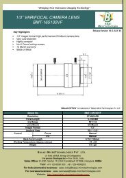
BMT-2098C-CL_USER MANUAL-CAMERALINK LINE SCAN CAMERA
We have 2048 Pixel Cameralink cameras, 2098 Pixel RGB Cameralink Line Scan Cameras. http://www.line-scan-camera.com/cameralink-line-scan-camera.php http://www.line-scan-camera.com/under-vehicle-surveillance-system.php http://www.line-scan-camera.com/medical-imaging-system.php
We have 2048 Pixel Cameralink cameras, 2098 Pixel RGB Cameralink Line Scan Cameras.
http://www.line-scan-camera.com/cameralink-line-scan-camera.php
http://www.line-scan-camera.com/under-vehicle-surveillance-system.php
http://www.line-scan-camera.com/medical-imaging-system.php

You also want an ePaper? Increase the reach of your titles
YUMPU automatically turns print PDFs into web optimized ePapers that Google loves.
Tri-Linear Series: <strong>BMT</strong>-<strong>2098C</strong>-<strong>CL</strong> User Manual<br />
Information!<br />
VDDs are connected together inside the camera.<br />
Warning!<br />
Do not reverse the polarity of the input power to the camera. Reversing<br />
the polarity of the input power can damage the camera and leave it<br />
non-operational<br />
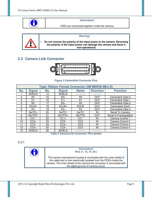
2.3 Camera Link Connector<br />
Figure 3 Cameralink Connector Pins<br />
Type: Ribbon Female Connector (3M MDR26 Mini D)<br />
No. Signal No. Signal Name Direction Function<br />
1 SHIELD 14 SHIELD ------------ ------------<br />
2 X0- 15 X0+ X0 OUT Cameralink Data 0<br />
3 X1- 16 X1+ X1 OUT Cameralink Data 1<br />
4 X2- 17 X2+ X2 OUT Cameralink Data 2<br />
5 X<strong>CL</strong>IK- 18 X<strong>CL</strong>IK+ X<strong>CL</strong>IK OUT Cameralink Clock<br />
6 X3- 19 X3+ X3 OUT Cameralink Data 3<br />
7 SerTC+ 20 SerTC- SerTC IN Serial To Camera<br />
8 SerTFG- 21 SerTFG+ SerTFG OUT Serial to Framegrabber<br />
9 CC1- 22 CC1+ CC1 IN Camera Control 1<br />
10 CC2+ 23 CC2- CC2 IN Camera Control 2<br />
11 CC3- 24 CC3+ CC3 IN Camera Control 3<br />
12 CC4+ 25 CC4- CC4 IN Camera Control 4<br />
13 SHIELD 26 SHIELD ------------ ------------<br />
Table 5 CameraLink Connector Pins details<br />
2.3.1<br />
Information!<br />
Pins (1, 13, 14, 26 )<br />
The camera mechanical housing is connected with the outer shield of<br />
the cable and is then electrically isolated from the PCB’s inside the<br />
camera. The inner shield of the camera link connector is connected with<br />
the digital ground of camera circuit.<br />
2015-16 Copyright BalaJi MicroTechnologies Pvt. Ltd. Page 9