Infrared line cameras for industrial temperature measurement ...
Infrared line cameras for industrial temperature measurement ...
Infrared line cameras for industrial temperature measurement ...

You also want an ePaper? Increase the reach of your titles
YUMPU automatically turns print PDFs into web optimized ePapers that Google loves.
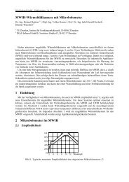
DIAS <strong>Infrared</strong> GmbH – Publications – No. 14 1<br />
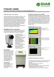
<strong>Infrared</strong> <strong>line</strong> <strong>cameras</strong> <strong>for</strong> <strong>industrial</strong> <strong>temperature</strong> <strong>measurement</strong><br />
Peter Drögmöller a , Günter Hofmann b , Helmut Budzier b,c , Thomas Reichardt b , Manfred Zimmerhackl b<br />
a MIKRON Instruments Co., Inc.; b DIAS <strong>Infrared</strong> GmbH;<br />
c Dresden University of Technology, Institute <strong>for</strong> Solid State Electronics<br />
Abstract<br />
The PYROLINE/MikroLine <strong>cameras</strong> provide continuous, non-contact <strong>measurement</strong> of <strong>line</strong>ar <strong>temperature</strong><br />
distributions. Operation in conjunction with the IR_LINE software provides data recording,<br />
real-time graphical analysis, process integration and camera-control capabilities.<br />
One system is based on pyroelectric <strong>line</strong> sensors with either 128 or 256 elements, operating at frame<br />
rates of 128 and 544 Hz respectively. Temperatures between 0 and 1300 °C are measurable in four<br />
distinct spectral ranges; 8–14 µm <strong>for</strong> low <strong>temperature</strong>s, 3–5 µm <strong>for</strong> medium <strong>temperature</strong>s, 4.8–5.2 µm<br />
<strong>for</strong> glass-<strong>temperature</strong> applications and 1.4–1.8 µm <strong>for</strong> high <strong>temperature</strong>s.<br />
A newly developed IR-<strong>line</strong> camera (HRP 250) based upon a thermoelectrically cooled, 160element,<br />
PbSe detector array operating in the 3–5 µm spectral range permits the thermal gradients of<br />
fast moving targets to be measured in the range 50–180 °C at a maximum frequency of 18 kHz. This<br />
special system was used to measure <strong>temperature</strong> distributions on rotating tires at velocities of more<br />
than 300 km/h (190 mph). A modified version of this device was used <strong>for</strong> real-time <strong>measurement</strong> of<br />
disk-brake rotors under load.<br />
Another <strong>line</strong> camera consisting a 256 element InGaAs array was developed <strong>for</strong> the spectral range of<br />
1.4–1.8 µm to detect impurities of polypropylene and polyethylene in raw cotton at frequencies of<br />
2.5–5 kHz.<br />
1 Introduction<br />
Temperature <strong>measurement</strong> plays an important role in many <strong>industrial</strong>-processing applications. Of<br />
particular importance is the frequent need <strong>for</strong> non-contact <strong>measurement</strong>s and data to be presented in<br />
the <strong>for</strong>m of a two-dimensional image. Since most <strong>industrial</strong> production processes will involve the<br />
movement of objects in one direction at a known speed, one-dimensional array <strong>cameras</strong> can be used to<br />
produce such images by repetitive, high-speed scanning, thereby avoiding the considerably higher<br />
costs associated with <strong>cameras</strong> based upon two-dimensional sensor arrays.<br />
Many IR-<strong>line</strong> <strong>cameras</strong> are available which utilize cooled, IR-semiconductor detectors and optomechanical<br />
scanners <strong>for</strong> one-dimensional beam deflection. Principle disadvantages of these <strong>line</strong> scanners<br />
brought about modern IR-<strong>line</strong> <strong>cameras</strong> using <strong>line</strong>ar arrays that do not need opto-mechanical scanners.<br />
In contrast to <strong>line</strong> scanners where the circular <strong>measurement</strong> area is <strong>line</strong>arly moved over the<br />
measured object by the scanner, <strong>line</strong>ar arrays can record the <strong>temperature</strong> distribution in multiple points<br />
on one <strong>line</strong> of the object simultaneously. More advantages occur through operation of uncooled IRarrays.<br />
In the following chapter, IR-<strong>line</strong> <strong>cameras</strong> based on <strong>line</strong>ar arrays will be described. These <strong>cameras</strong><br />
were specifically developed to satisfy the demands of <strong>industrial</strong>-process <strong>measurement</strong>s, which often<br />
include the need <strong>for</strong> continuous operation in harsh environments. In such applications, high reliability,<br />
long-time stability and, most significantly, an optimal price-per<strong>for</strong>mance ratio play important roles.<br />
2 Uncooled <strong>Infrared</strong> <strong>line</strong> <strong>cameras</strong> based on pyroelectric <strong>line</strong>ar arrays<br />
The key component of an IR-<strong>line</strong> camera (PYROLINE/MikroLine) is the uncooled pyroelectric <strong>line</strong>ar<br />
array. Fig. 1 shows the fundamental structure. The detector array consists of 128 or 256 pixels,
DIAS <strong>Infrared</strong> GmbH – Publications – No. 14 2<br />
each with an active area of AS = a · b, aligned in the y-direction with center-to-center pitch c. The<br />
chopped radiation signal Φs passes through an IR-transmissive window be<strong>for</strong>e striking the active surface<br />
of the pyroelectric chip where it is absorbed, causing a <strong>temperature</strong> change which generates an<br />
electrical charge via the pyroelectric effect. With an integrated read out circuit, (ROIC) a multiplexed<br />
voltage output signal u'S will be produced.<br />
front electrode<br />
AS b<br />
a<br />
Φ<br />
S<br />
u'<br />
S<br />
input structure multiplexer output structure<br />
c<br />
pyroelectric chip<br />
d<br />
back electrode<br />
Fig. 1: Fundamental structure of a <strong>line</strong>ar pyroelectric array<br />
The <strong>line</strong>ar array, 128-LT, includes a lithium-tantalate chip with 128 sensitive elements and a thickness<br />
of 20 µm. The pixel size is a × b = 90 × 100 µm 2 with a pitch, c, of 100 µm. The signals generated<br />
in the sensitive elements are processed in a CMOS-circuit that contains both analog and digital<br />
sections. The analog part realizes the sensor signal processing which includes the multiplexer, a lownoise<br />
pre-amplifier (with individual gain control <strong>for</strong> each pixel), the output amplifier, an RC low-pass<br />
filter and a sample-and-hold circuit. The digital section is responsible <strong>for</strong> the clock pulse supply <strong>for</strong><br />
the analog part. The pyroelectric chip and CMOS-read out circuit are located on a thick-film wiring<br />
carrier, which is mounted into a hermetically sealed, metal housing. Incident light arrives at the detector<br />
elements through an IR-filter. Filters with specific pass-band characteristics are used to optimize<br />
the per<strong>for</strong>mance of the detector arrays <strong>for</strong> operation in the 8–14 µm, 3–5 µm, 4.8–5.2 µm and 1.4–<br />
1.8 µm spectral bands. The sensitivity of the detector array was maximized through the use of<br />
reduced-thickness (5 µm) pyroelectric chips fabricated using ion-beam etching techniques. This<br />
detector type is named 128-LT-I. Improved spatial resolution was achieved using arrays with 256<br />
elements and a center-to-center pitch of 50 µm (type 256-LT-I) 1 .<br />
The camera system PYROLINE 128/MikroLine M2128 was developed primarily <strong>for</strong> use with pyroelectric,<br />
<strong>line</strong>ar, 128-element-arrays, 128-LT and 128-LT-I. Fig. 2 shows the complete camera. It<br />
consists of a robust, <strong>industrial</strong> housing that can be equipped with integrated water-cooling and air<br />
purge <strong>for</strong> lens system. The camera assembly (Fig. 3) includes the pyroelectric array, a chopper module<br />
(chopper frequency 128 Hz), the IR-optics (not shown in Fig. 3) as well as the entire analog and digital<br />
signal processing. The analog-digital converter operates with 16-bit resolution. The <strong>cameras</strong> are configured<br />
with a signal processor that can fulfill several process control tasks beyond the standard analysis<br />
of <strong>measurement</strong> data. The signal processor converts the measured data into <strong>temperature</strong>s taking<br />
account of ambient <strong>temperature</strong>, emissivity, transmissivity, as well as the different sensitivities of each<br />
individual pixel. Up to 128-scanned <strong>temperature</strong> distributions can be stored in real time. Multiple control<br />
commands or alarm signals based upon measured data are available via a standard COM-port and<br />
dedicated I/O <strong>line</strong>s.<br />
z<br />
x<br />
y
DIAS <strong>Infrared</strong> GmbH – Publications – No. 14 3<br />
Fig. 2: <strong>Infrared</strong> <strong>line</strong> camera PYROLINE/MikroLine<br />
Fig. 3: IR-<strong>line</strong> camera assembly (without optics)<br />
Two trigger inputs allow the synchronization of the data recording, independent of outside events:<br />
one <strong>for</strong> the recording and the other <strong>for</strong> the complete picture. For instance, the inclusion of an incremental<br />
encoder makes it possible to measure the <strong>temperature</strong> of rotating objects independently of the<br />
rotation speed where the spatial correlation between the measured <strong>temperature</strong> and the position on the<br />
measured object is required.<br />
Since the camera must be located near the process away from the control room, an RS232 COMport<br />
serves <strong>for</strong> control, monitoring and data transmission. In combination with a computer, this connection<br />
is used to program, parameterize and record <strong>measurement</strong> data. Optionally data transmission<br />
in real time (up to 128 Hz frame rate) over long distances can be realized by fiber optic connections in<br />
combination with a PCMCIA-transceiver card.
DIAS <strong>Infrared</strong> GmbH – Publications – No. 14 4<br />
A user-friendly analyses and control software is available to operate the camera with an external<br />
computer. This software includes:<br />
• Control and configuration of the camera<br />
• Display of the measured data normalized to different <strong>temperature</strong> distributions or images<br />
• Up to 32 regions of interests and alarms<br />
• Load, save and print of <strong>temperature</strong> distributions (profiles) or images<br />
• Single point <strong>temperature</strong> determination<br />
• Drivers <strong>for</strong> analog and digital computer output cards<br />
• Remote control via serial COM-port or network<br />
A data recording function permits postprocessing, e.g. time delayed replay of fast processes, display<br />
using a different scale or change in emissivity. Additional software options include data export and<br />
password protection.<br />
The <strong>cameras</strong> also work independently of an always-connected computer. Easy process control can<br />
be fulfilled via four independent, isolated inputs or outputs. All parameters <strong>for</strong> stand-alone operation<br />
can be configured with a computer through the RS232 COM-port. An integrated, non-volatile memory<br />
guarantees that the <strong>cameras</strong> remains programmed after a power loss.<br />
PYROLINE 128 8–14 µm<br />
(MikroLine M2128)<br />
PYROLINE 128 M 3–5 µm<br />
(MikroLine M2128 M)<br />
PYROLINE 128 G 4.8–5.2 µm<br />
(MikroLine M2128 G)<br />
PYROLINE 128 H 1.4–1.8 µm<br />
(MikroLine M2128 H)<br />
0–80 °C / 50–350 °C / 50–550°C / 450–1250 °C<br />
200–800 °C / 450–1250 °C<br />
250–1250 °C / 450–1250 °C<br />
600–1300 °C<br />
Fig. 4: Temperature and spectral ranges of pyroelectric IR-<strong>line</strong> camera (PYROLINE 128/MikroLine M2128)<br />
Four basic device variations <strong>for</strong> different applications were developed. Essential technical data are<br />
summarized in Table 1. The standard <strong>temperature</strong> ranges include <strong>temperature</strong>s of 0–1300 °C. Spectral<br />
ranges are 8–14 µm <strong>for</strong> low-<strong>temperature</strong> applications, 3–5 µm <strong>for</strong> <strong>measurement</strong> of medium <strong>temperature</strong>s,<br />
4.8–5.2 µm <strong>for</strong> glass applications and 1.4–1.8 µm <strong>for</strong> high <strong>temperature</strong> <strong>measurement</strong>s (Fig. 4).<br />
Four exemplary applications are shown in Fig. 5–8.
DIAS <strong>Infrared</strong> GmbH – Publications – No. 14 5<br />
PYROLINE<br />
MikroLine<br />
Table 1: Selected technical data of the <strong>line</strong> camera PYROLINE 128/MikroLine M2128<br />
128<br />
M2128<br />
128 M<br />
M2128 M<br />
128 G<br />
M2128 G<br />
128 H<br />
M 2128 H<br />
Spectral range 8–14 µm 3–5 µm 4.8–5.2 µm 1.4 –1.8 µm<br />
Measurement<br />
<strong>temperature</strong> range a<br />
0–80 °C / 50–350 °C * )<br />
50–550 °C / 450–1250 °C<br />
200–800 °C<br />
450–1250 °C<br />
250–1250 °C<br />
450–1250 °C<br />
600–1300 °C<br />
Aperture 40° × 0.3° 60° × 0.5° 60° × 0.5° 60° × 0.5°<br />
Spatial resolution<br />
(50 % modulation)<br />
6 mrad 9 mrad 9 mrad 9 mrad<br />
Measurement distance 10 cm – infinity 20 cm – infinity 20 cm – infinity 50 cm – infinity<br />
Accuracy b<br />
NETD b<br />
2 K at 100 °C or<br />
1 K + 1 % of true value<br />
1 K + 1 % of<br />
true value<br />
1 K + 1 % of<br />
true value<br />
1 K + 1 % of<br />
true value<br />
< 0.2 K * ) resp. < 0.5 K < 0.5 K < 1 K < 1 K<br />
Frame rate internal 128 Hz, selectable 128 Hz, 64 Hz, 32 Hz, ...<br />
Response time internal 16 ms, selectable: 2/<strong>measurement</strong> frequency<br />
Interface RS 232 wire (4 Hz max), RS 422 wire (32 Hz max),<br />
RS 232 fiber optic (32 Hz max), PCMCIA-fiber optic (128 Hz max)<br />
Digital interface 4 independently programmable I/O <strong>line</strong>s<br />
Digital input (trigger) optoisolator inputs (LED’s: 5 V ≤ VE ≤ 25 V)<br />
Digital output (alarm) optically coupled, electrically isolated open-collector outputs (IC ≤ 50 mA, VE ≤ 25 V)<br />
round connector with thread interlocking (16-pins)<br />
interlocking fiber optic- connector (2-fibers)<br />
water supply tubing (nominal width 4 mm, 2 bar max)<br />
compressed air tubing (nominal width 4 mm, 2 bar max)<br />
Housing IP65, optional with integrated water cooling system, air purge, swivel base<br />
Connectors c<br />
Weight ca. 3.2 kg<br />
Supply voltage 11–36 V DC / 10–20 VA<br />
Operating <strong>temperature</strong> camera: 0 to 50 °C, –25 to150 °C (with water cooling)<br />
system cable: –25 to 150 °C<br />
fiber optic: 0 to 70 °C<br />
Storage condition –20 to 70 °C, relative humidity 95 % max<br />
Software computer control and display program <strong>for</strong> Windows<br />
a different on request<br />
b <strong>for</strong> 32 Hz frame rate, black body, ambient <strong>temperature</strong> 25 °C<br />
c depending on configuration
DIAS <strong>Infrared</strong> GmbH – Publications – No. 14 6<br />
Fig. 5: Hot-spot recognition in mineral wool production 4<br />
Fig. 6: Temperature <strong>measurement</strong> of the outside wall of a rotating kiln 4
DIAS <strong>Infrared</strong> GmbH – Publications – No. 14 7<br />
Fig. 7: Temperature <strong>measurement</strong> of float glass after the annealing process 4<br />
Fig. 8: Measurement of <strong>temperature</strong> distribution in steel ingots 4
DIAS <strong>Infrared</strong> GmbH – Publications – No. 14 8<br />
In order to expand the range of applications, a new camera series using an uncooled, pyroelectric,<br />
256-element array (256-LT-I) was developed. These <strong>cameras</strong> (PYROLINE 256, MikroLine M2256)<br />
provide improved spatial resolution and <strong>measurement</strong> frequencies up to 544 Hz.<br />
Note: The per<strong>for</strong>mance improvements listed above have not necessitated any changes to the camera’s<br />
mechanical or optical-path dimensions.<br />
Fig. 9 shows the block diagram of this camera. The signal processing electronics includes:<br />
• Close to sensor electronics<br />
• Digital clock pulse generator<br />
• Analog-to-digital converter<br />
• Image difference processing (IDP)<br />
• Chopper motor controller<br />
• Sensor <strong>temperature</strong> stabilization<br />
• Printed circuit board <strong>for</strong> signal input and output<br />
• DC/DC- printed circuit board<br />
infrared<br />
radiation<br />
optic<br />
camera head<br />
cooler/chopper pcb fiber pcb<br />
TE-cooler<br />
Sensor<br />
clock driver<br />
chopper<br />
controller<br />
sensor PCB<br />
pre-amplifier<br />
DC supply<br />
<strong>temperature</strong><br />
sensors<br />
digital PCB<br />
ADC<br />
clock generator<br />
IDP<br />
DC/filter pcb<br />
power supply<br />
fiber optic<br />
driver<br />
serializer<br />
microcontroller<br />
digital<br />
input/output<br />
Fig. 9: Block diagram of the camera electronic PYROLINE 256/MikroLine M2256<br />
to PC<br />
to process<br />
Operation of the camera, image acquisition and data processor are controlled using the “IR_LINE”<br />
software, which communicates with the camera via a dedicated PCI card and fiber-optic cable. At this<br />
time, different spectral ranges (1.4–1.8 µm, 3–5 µm, 4.8–5.2 µm and 8–14 µm) and <strong>temperature</strong> range<br />
of 50–1300 ºC (<strong>temperature</strong> resolution < 1 K, corresponding to the conditions in Table 1) are possible<br />
with the <strong>line</strong> camera (PYROLINE 256, MikroLine M2256).<br />
3 High-speed infrared <strong>line</strong> <strong>cameras</strong><br />
High-speed infrared <strong>line</strong> <strong>cameras</strong> with frame rates in the kHz range were developed especially <strong>for</strong><br />
the <strong>temperature</strong> distribution <strong>measurement</strong> of fast moving objects. One particular application is in a<br />
high-speed tire test station. There<strong>for</strong>e, the special camera system, HRP 250, was developed. A <strong>line</strong>ar<br />
array of 160 PbSe-photo resistors with a thermoelectric cooler is used as a detector. The time constant<br />
of the photo resistors is less than 10 µs. The camera system consists of a camera head, a controller,<br />
two black body sources <strong>for</strong> on<strong>line</strong> calibration and a computer. The camera head and PCI-card, including<br />
the fiber optic data transmission, are basically the same as the earlier camera systems,<br />
PYROLINE 256/MikroLine M2256, only the IR-detector assembly is different. Zero and Angle im-
DIAS <strong>Infrared</strong> GmbH – Publications – No. 14 9<br />
pulses of the encoder are needed as an input signal <strong>for</strong> the camera. The data output is a profile on the<br />
screen, a file or a digital impulse. A computer controls the operating elements of the camera.<br />
All 160 pixels of a <strong>line</strong> are measured simultaneously. Due to the rotation of the object, a two dimensional<br />
picture (profile) is generated. The encoder synchronizes the camera with the turning object. An<br />
encoder with 1º resolution (360 <strong>line</strong>s per rotation) is preferred. The accruing profile (e.g. tread area of<br />
a tire) consists of 160 columns (recorded by 160 pixels) and 360 rows (triggered by the encoder with<br />
1º resolution). Different encoders with higher resolutions are possible also. The following selected<br />
technical data were achieved by the camera system HRP 250:<br />
Table 2: Selected technical data of the camera system HRP 250<br />
Measured <strong>temperature</strong> range 50–180 ºC<br />
Spectral range 3–5 µm<br />
Temperature resolution 0.5 K at 50 ºC<br />
Precision 2 K ± 2 % of true value<br />
Aperture 30º x 0.13º<br />
Spatial resolution 3 mrad<br />
Frame rate 18 kHz<br />
Temperature distributions in rotating tires at a speed up to 300 km/h can be measured with the a<strong>for</strong>ementioned<br />
camera system. Exemplary <strong>measurement</strong> results are shown in Fig. 10.<br />
Fig. 10: Temperature profile of a rotating tire’s tread area 4<br />
A modified version of the HRP 250 system was used <strong>for</strong> true time, <strong>temperature</strong> <strong>measurement</strong>s of<br />
rotating brake disks. There<strong>for</strong>e, the frequency was set to 1.2 kHz and the <strong>temperature</strong> range was extended<br />
up to 800 ºC. The results are shown in Fig. 11.
DIAS <strong>Infrared</strong> GmbH – Publications – No. 14 10<br />
Fig. 11: Temperature distribution of one-face brake rotors 4<br />
Based on the same basic device concept, a 256 element InGaAs array with a spectral range of 1.4–<br />
1.8 µm was used to build a high-speed <strong>line</strong> camera system which was used to detect impurities of polypropylene<br />
and polyethylene in raw cotton at frequencies of 2.5–5 kHz. The material identification is<br />
done by wavelength selective, reflection <strong>measurement</strong>s in the near infrared (NIR) range. The main<br />
components are two camera heads, each with a 256 element InGaAs <strong>line</strong> detector and a bandpass filter.<br />
Classification of the signal pairs through the similar distance method per<strong>for</strong>ms the material recognition.<br />
Fig. 12 shows a measured sample on an experimental setup 3 .<br />
moving direction of the drum<br />
25 50 75 100 125 150 175 200 225<br />
pixel of the sensor array<br />
Fig. 12: Impurity detection in raw cotton (black pixel are classified as impurity)
DIAS <strong>Infrared</strong> GmbH – Publications – No. 14 11<br />
4 Conclusion<br />
The IR <strong>cameras</strong> PYROLINE 128/MikroLine M2128 allow the non-contact, continuous <strong>measurement</strong><br />
of <strong>temperature</strong> distributions and their analysis. The principal part of the system is an uncooled<br />
pyroelectric <strong>line</strong> detector with 128 elements operating at a frame rate of 128 Hz. Standard <strong>measurement</strong><br />
ranges include <strong>temperature</strong>s of 0 to 1300 ºC. Standard spectral ranges are 8–14 µm <strong>for</strong> low<strong>temperature</strong><br />
applications, 3–5 µm <strong>for</strong> <strong>measurement</strong> of medium <strong>temperature</strong>s, 4.8–5.2 µm <strong>for</strong> glass<br />
applications and 1.4–1.8 µm <strong>for</strong> high <strong>temperature</strong> <strong>measurement</strong>s.<br />
Based on a new universal camera concept, IR <strong>line</strong> <strong>cameras</strong> with uncooled pyroelectric, <strong>line</strong>ar 256<br />
element arrays, as well as special high-speed systems with <strong>line</strong>ar PbSe- and InGaAs-arrays (frame<br />
rates in the kHz range) were developed. This basic camera system was also used <strong>for</strong> IR-2D camera<br />
systems with uncooled 2D pyroelectric and micro-bolometer arrays. There<strong>for</strong>e a comprehensive variety<br />
of powerful <strong>cameras</strong> can be offered, which can be used to monitor <strong>industrial</strong> processes.<br />
Acknowledgements<br />
This research was partially supported by the German Federal Ministry of Education and Research.<br />
References<br />
1. V. Norkus, G. Gerlach, and G. Hofmann, „High-resolution pyroelectric <strong>line</strong>ar arrays based on<br />
LiTaO3“, SPIE 4369, pp. 322-331, 2001<br />
2. H. Budzier, M. Zimmerhackl, V. Krause, and G. Hoven, „High speed IR camera <strong>for</strong> contactless<br />
<strong>temperature</strong> <strong>measurement</strong> on rotating tires“, Proc. Sensor 99, pp. 41–46, Vol. 1, 1999<br />
3. B. Vollheim, H. Budzier, V. Krause, G. Gerlach, T. Pusch, M. Mägel, and P. Offermann, “NIR<br />
Camera System <strong>for</strong> the Detection of Contamination in Raw Cotton“, Proc. Sensor 2001, Vol. 1,<br />
pp. 155–160, 2001<br />
4. www.cmv.de, www.dias-gmbh.de, www.dias-gmbh.com