Linear Arrays with 256 Pixels based on Lithium Tantalate Introduction
Linear Arrays with 256 Pixels based on Lithium Tantalate Introduction
Linear Arrays with 256 Pixels based on Lithium Tantalate Introduction

You also want an ePaper? Increase the reach of your titles
YUMPU automatically turns print PDFs into web optimized ePapers that Google loves.
DIAS Infrared GmbH – Publicati<strong>on</strong>s – No. 15 1<br />
<str<strong>on</strong>g>Linear</str<strong>on</strong>g> <str<strong>on</strong>g>Arrays</str<strong>on</strong>g> <str<strong>on</strong>g>with</str<strong>on</strong>g> <str<strong>on</strong>g>256</str<strong>on</strong>g> <str<strong>on</strong>g>Pixels</str<strong>on</strong>g> <str<strong>on</strong>g>based</str<strong>on</strong>g> <strong>on</strong> <strong>Lithium</strong> <strong>Tantalate</strong><br />
Reinhard Köhler 1,2 , Volkmar Norkus 1,2 , Gerald Gerlach 1 ,<br />
Jens Vollheim 2 , Norbert Heß 2 , Günter Hofmann 2<br />
1 Dresden University of Technology, Institute for Solid State Electr<strong>on</strong>ics<br />
2 DIAS Infrared GmbH<br />
Introducti<strong>on</strong><br />
Pyroelectric detectors are used as a budget-priced alternative to semic<strong>on</strong>ductor infrared detectors.<br />
The applicati<strong>on</strong> spectrum includes simple moti<strong>on</strong> detectors, n<strong>on</strong>-c<strong>on</strong>tact temperature measurement<br />
systems, IR spectrometers and gas analyzers, for example.<br />
Based <strong>on</strong> more than 20 years of experience in development, producti<strong>on</strong> and applicati<strong>on</strong> of pyroelectric<br />
single element detectors and detector arrays, a new generati<strong>on</strong> of lithium tantalate linear arrays<br />
<str<strong>on</strong>g>with</str<strong>on</strong>g> better spatial and thermal resoluti<strong>on</strong> than in the former detector generati<strong>on</strong> [1, 2, 3] has been developed.<br />
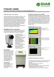
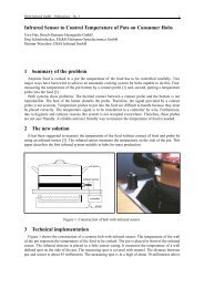
Figure 1 shows the fundamental structure of linear pyroelectric arrays.<br />
sensitive area A s<br />
z<br />
y<br />
b<br />
x<br />
a<br />
multiplexer<br />
Φ s<br />
c<br />
output driver<br />
v s '<br />
t p<br />
comm<strong>on</strong> electrode<br />
pixeled electrode<br />
pyroelectric chip<br />
read-out circuit<br />
Fig. 1: Fundamental structure of a linear pyroelectric array<br />
In general, LiTaO3 detectors are hybrid comp<strong>on</strong>ents. The introduced linear arrays are an arrangement<br />
of a pyroelectric detector chip, printed circuit board (PCB), anisotropically etched silic<strong>on</strong> aperture<br />
and a CMOS read-out circuit in 0.8 µm technique. Interc<strong>on</strong>necti<strong>on</strong>s between detector pixels and<br />
read-out circuit are carried out by wire b<strong>on</strong>ding. All comp<strong>on</strong>ents are mounted in a hermetically sealed<br />
16 pin metal package. Figure 1 shows a secti<strong>on</strong>al view schematic of the detector array.<br />
Main applicati<strong>on</strong> are line cameras for temperature measurement in industrial use [4, 5, 8]. One of<br />
such cameras, the PYROLINE <str<strong>on</strong>g>256</str<strong>on</strong>g> is shortly characterized in this paper. The PYROLINE <str<strong>on</strong>g>256</str<strong>on</strong>g> cameras<br />
provide c<strong>on</strong>tinuous, n<strong>on</strong>-c<strong>on</strong>tact measurement of linear temperature distributi<strong>on</strong>s. Operati<strong>on</strong> in<br />
c<strong>on</strong>juncti<strong>on</strong> <str<strong>on</strong>g>with</str<strong>on</strong>g> the IR_LINE software provides data recording, real-time graphical analysis, process<br />
integrati<strong>on</strong> and camera-c<strong>on</strong>trol capabilities. The system is <str<strong>on</strong>g>based</str<strong>on</strong>g> <strong>on</strong> pyroelectric linear arrays <str<strong>on</strong>g>with</str<strong>on</strong>g> <str<strong>on</strong>g>256</str<strong>on</strong>g><br />
elements, operating at frame rates of up to 545 Hz. Temperatures between 50 and 1300 °C are measurable<br />
in four distinct spectral ranges; 8–14 µm for low temperatures, 3–5 µm for medium temperatures,<br />
4.8–5.2 µm for glass-temperature applicati<strong>on</strong>s and 1.4–1.8 µm for high temperatures.
DIAS Infrared GmbH – Publicati<strong>on</strong>s – No. 15 2<br />
1 LiTaO3 Detector Chip Technology<br />
The introduced linear arrays have <str<strong>on</strong>g>256</str<strong>on</strong>g> resp<strong>on</strong>sive elements <str<strong>on</strong>g>with</str<strong>on</strong>g> an area of 40 × 50 µm² arranged in<br />
a pitch of 50 µm. Starting material are polarized single-crystal LiTaO3 wafers <str<strong>on</strong>g>with</str<strong>on</strong>g> a diameter of 2.5″<br />
and a thickness of 500 µm.<br />
First, the wafer is cut into smaller subwafers <str<strong>on</strong>g>with</str<strong>on</strong>g> an area of about 20 × 20 mm². Afterwards, <strong>on</strong>to<br />
the polished side of the subwafer metallizati<strong>on</strong> layers of bottom electrode system (Ni80Cr20 and Au)<br />
are evaporated and structured by lift-off technique. Difficulties in these steps are caused by the small<br />
pattern size (minimum of about 3 µm) in c<strong>on</strong>necti<strong>on</strong> <str<strong>on</strong>g>with</str<strong>on</strong>g> the risk of lightning discharges due to electrificati<strong>on</strong><br />
of the pyroelectric material.<br />
In next step, the wafers are fixed <strong>on</strong>to precisi<strong>on</strong> metal plates <str<strong>on</strong>g>with</str<strong>on</strong>g> less than 5 µm thin special cement.<br />
Afterwards, the wafers are thinned down to a thickness of about 40 µm by lapping <str<strong>on</strong>g>with</str<strong>on</strong>g> silic<strong>on</strong><br />
carbide, followed by polishing procedure, which reduces the thickness to about 25 µm. After mechanical<br />
processing the resp<strong>on</strong>sive elements are i<strong>on</strong> beam etched down to 5 µm. Now the LiTaO3 chip has a<br />
25 µm thick supporting frame and a 5 µm thin area for highly sensitive resp<strong>on</strong>sive elements.<br />
The top electrode metallizati<strong>on</strong> system is evaporated and lift-off structured again. The resp<strong>on</strong>sive<br />
elements themselves are coated <str<strong>on</strong>g>with</str<strong>on</strong>g> low reflecting 10 nm Ni80Cr20. An additi<strong>on</strong>al gold layer reinforces<br />
all other c<strong>on</strong>ductive tracks.<br />
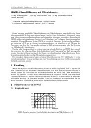
Fig. 2: Detector pixels <str<strong>on</strong>g>with</str<strong>on</strong>g> i<strong>on</strong> beam etched trenches (left: reed geometry, right: fence geometry)<br />
In order to minimize the thermal cross-talk small trenches are i<strong>on</strong> beam etched between the resp<strong>on</strong>sive<br />
elements. The results of trench etching are two types of thermal insulated pixels – a fence like<br />
geometry and a reed like <strong>on</strong>e. Both types are represented in figure 2. In both pictures the pitch of the<br />
pixels is 50 µm. The fence like pixel structure is characterized by a higher mechanical stability while<br />
the reed structure is better thermally insulated. The applied i<strong>on</strong> beam etching parameters are str<strong>on</strong>gly<br />
dependent <strong>on</strong> the etching depth, the structure size and the desired side wall angle. Typical parameters<br />
and etching rates are shown in table 1.<br />
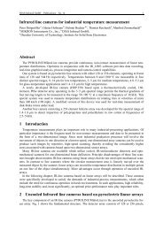
The etched 5 µm thin LiTaO3 reeds in figure 3 dem<strong>on</strong>strate the outstanding performance of the i<strong>on</strong><br />
beam milling process. For etching mask photo resist AZ 4562 has been used.<br />
accellerati<strong>on</strong><br />
voltage Vacc in V<br />
Table 1: I<strong>on</strong> beam etching parameters for LiTaO3<br />
i<strong>on</strong> current density<br />
SI in mA / cm²<br />
LiTaO3 etching rate<br />
in µm / h<br />
photo resist etching<br />
rate in µm / h<br />
normal power 800 0,6 2.3–2.4 1.55–1.75<br />
low power 250 0,6 1.04–1.27 0.59–0.77
DIAS Infrared GmbH – Publicati<strong>on</strong>s – No. 15 3<br />
The two i<strong>on</strong> beam etching processes described above, simultaneously separate the 10 linear array<br />
detector chips placed <strong>on</strong> <strong>on</strong>e subwafer.<br />
Finally, the chips are detached and cleaned. In order to cure damages, which were caused by i<strong>on</strong><br />
beam etching processes, the chips are annealed by a soft thermal treatment.<br />
2 Read-out Circuit<br />
Fig. 3: SEM image of LiTaO3 reeds (50 µm pitch)<br />
The 75 mW c<strong>on</strong>suming read-out circuit is especially designed for detectors <str<strong>on</strong>g>with</str<strong>on</strong>g> <str<strong>on</strong>g>256</str<strong>on</strong>g> pixels. The<br />
circuit is produced in 0.8 µm CMOS technology. It c<strong>on</strong>sists of an analogue and a digital part and is<br />
optimized for low noise and high linearity. Figure 4 shows the circuit diagram of its analogue path.<br />
First stage works as a charge-current transducer in which the pyroelectric elements are operated in<br />
current mode. After integrati<strong>on</strong> each signal is stored in a sample-&-hold stage. Finally, the <str<strong>on</strong>g>256</str<strong>on</strong>g> channels<br />
are switched to the output driver by a multiplexer.<br />
input<br />
b<strong>on</strong>ding pad<br />
Cp<br />
VVR<br />
CS<br />
RT1<br />
CT1<br />
1 C-coupled<br />
amplifier<br />
st INP1 INP2<br />
pyroelectric<br />
capacitor<br />
charge to<br />
voltage<br />
c<strong>on</strong>verter<br />
RC low pass<br />
3 Detector Assembly<br />
CA<br />
VDR<br />
CI<br />
RT2<br />
VSH<br />
CT2 CSH<br />
2 nd RC low pass<br />
sample<br />
& hold<br />
VAS(1)<br />
VAS(n)<br />
1 1<br />
VAS(<str<strong>on</strong>g>256</str<strong>on</strong>g>)<br />
S&H buffer<br />
multiplexer<br />
Fig 4: Circuit diagram of analogue path of the read-out circuit<br />
output driver<br />
output<br />
b<strong>on</strong>ding pad<br />
As menti<strong>on</strong>ed above, the detectors are hybrid arrangements. An adhesive <strong>on</strong>to a micromachined<br />
silic<strong>on</strong> carrier b<strong>on</strong>ds the fragile LiTaO3 chips. Simultaneously, this carrier acts as an optical aperture,<br />
i.e. as an optical shield against heat absorpti<strong>on</strong> in the pixel surroundings. Afterwards, both the sandwich<br />
c<strong>on</strong>structi<strong>on</strong> and the read-out circuit are mounted <strong>on</strong>to PCB <str<strong>on</strong>g>with</str<strong>on</strong>g> a c<strong>on</strong>ductive adhesive. For the<br />
c<strong>on</strong>necti<strong>on</strong>s between read-out circuit and PCB thermal compressi<strong>on</strong> b<strong>on</strong>ding is used whereas the c<strong>on</strong>necti<strong>on</strong>s<br />
between pyroelectric chip and input stages of read-out circuit are realized by ultras<strong>on</strong>ic fine
DIAS Infrared GmbH – Publicati<strong>on</strong>s – No. 15 4<br />
pitch b<strong>on</strong>ding. A special b<strong>on</strong>ding wedge is used together <str<strong>on</strong>g>with</str<strong>on</strong>g> an AlSi wire <str<strong>on</strong>g>with</str<strong>on</strong>g> a diameter of 17.5 µm<br />
in order to produce b<strong>on</strong>ds <str<strong>on</strong>g>with</str<strong>on</strong>g> a pitch of 50 µm.<br />
pyroelectric<br />
chip<br />
IR window<br />
black coating<br />
read-out circuit<br />
ceramic<br />
carrier<br />
support<br />
PCB<br />
IR window<br />
read-out circuit<br />
black coating<br />
support<br />
silic<strong>on</strong><br />
aperture<br />
pyroelectric<br />
chip<br />
Fig. 5: Secti<strong>on</strong>al view of <str<strong>on</strong>g>256</str<strong>on</strong>g> pixels LiTaO3 linear arrays (left: <str<strong>on</strong>g>with</str<strong>on</strong>g>out silic<strong>on</strong> aperture<br />
and absorpti<strong>on</strong> black, right: <str<strong>on</strong>g>with</str<strong>on</strong>g> silic<strong>on</strong> aperture and absorpti<strong>on</strong> black)<br />
Fig. 6: LiTaO3 arrays in metal package <str<strong>on</strong>g>with</str<strong>on</strong>g>out lid<br />
(left: standard assembly, right: face down assembly)<br />
For optimum heat absorpti<strong>on</strong> a broadband absorbing black coating or a special λ/4 thin film absorber<br />
can be used. Regardless of the applicati<strong>on</strong> of an absorber <strong>on</strong> top of the resp<strong>on</strong>sive elements, the<br />
silic<strong>on</strong> precisi<strong>on</strong> aperture must be black coated in order to avoid heat radiati<strong>on</strong> transmissi<strong>on</strong> and reflexi<strong>on</strong><br />
inside the package. Before this black coating, the PCB <str<strong>on</strong>g>with</str<strong>on</strong>g> the parts has to be mounted face<br />
down into the case header. The c<strong>on</strong>necti<strong>on</strong>s between PCB and package pins are b<strong>on</strong>ded. An AD590<br />
temperature detector is integrated <strong>on</strong>to the bottom of the housing as well.<br />
Now the absorber can be deposited. A silver black coating has been optimized for the LiTaO3 detectors.<br />
The coating <str<strong>on</strong>g>with</str<strong>on</strong>g> a thickness of about 5 µm is electrically c<strong>on</strong>ductive and is distinguished by a
DIAS Infrared GmbH – Publicati<strong>on</strong>s – No. 15 5<br />
band absorbance of about 0.92 for a 500 K black radiator in the range of 2–20 µm [6]. Opti<strong>on</strong>al <str<strong>on</strong>g>with</str<strong>on</strong>g><br />
the applicati<strong>on</strong>, the spectral range can be determined <str<strong>on</strong>g>with</str<strong>on</strong>g>in 1.2 µm and 20 µm by a band pass window<br />
in the lid of the package. Finally, the package is sealed hermetically. In additi<strong>on</strong>, a detector type <str<strong>on</strong>g>with</str<strong>on</strong>g>out<br />
absorpti<strong>on</strong> black and silic<strong>on</strong> aperture enables a more easy assembling but doesn’t have as high<br />
performance as the more complicated <strong>on</strong>e. In this case PCB <str<strong>on</strong>g>with</str<strong>on</strong>g> detector chip is not face down<br />
mounted.<br />
In figure 5 both types are represented schematically. Figure 6 shows completely mounted (except<br />
the lid) arrays of both <str<strong>on</strong>g>256</str<strong>on</strong>g> pixels arrays.<br />
4 Detector Characteristics<br />
The described detectors are still under development. All detector measurements has been performed<br />
in unsealed packages, <str<strong>on</strong>g>with</str<strong>on</strong>g>out black coating and <str<strong>on</strong>g>with</str<strong>on</strong>g> an antireflecti<strong>on</strong>-coated 8–14 µm Ge filter.<br />
R V/R V0<br />
1.4<br />
1.2<br />
1.0<br />
0.8<br />
0.6<br />
0.4<br />
1 32 64 96 128 160 192 224 <str<strong>on</strong>g>256</str<strong>on</strong>g><br />
Pixel #<br />
Fig.7: Resp<strong>on</strong>sivity distributi<strong>on</strong> of a LiTaO3 array <str<strong>on</strong>g>with</str<strong>on</strong>g>out trenches at fmod = 128 Hz<br />
Its voltage resp<strong>on</strong>sivity amounts up to more than 600.000 V/W at a rectangular modulati<strong>on</strong> frequency<br />
fmod = 128 Hz. The voltage resp<strong>on</strong>sivity distributi<strong>on</strong> RV /RV0 of a detector <str<strong>on</strong>g>with</str<strong>on</strong>g>out trenches at a<br />
modulati<strong>on</strong> frequency of 128 Hz is shown in figure 7.<br />
MTF<br />
1.0<br />
0.8<br />
0.6<br />
0.4<br />
0.2<br />
<str<strong>on</strong>g>with</str<strong>on</strong>g>out trenches<br />
0<br />
0 2 4 6<br />
R in lp/mm<br />
8<br />
MTF<br />
1.0<br />
0.8<br />
0.6<br />
0.4<br />
0.2<br />
<str<strong>on</strong>g>with</str<strong>on</strong>g> trenches<br />
0<br />
0 2 4 6<br />
R in lp/mm<br />
Fig. 8: Measured MTF of two LiTaO3 arrays <str<strong>on</strong>g>with</str<strong>on</strong>g> <str<strong>on</strong>g>256</str<strong>on</strong>g> pixels at fmod = 128 Hz<br />
Figure 8 shows the improved modulati<strong>on</strong> transfer functi<strong>on</strong> MTF of a detector <str<strong>on</strong>g>with</str<strong>on</strong>g> thermal insulating<br />
trenches in comparis<strong>on</strong> to a detector <str<strong>on</strong>g>with</str<strong>on</strong>g>out trenches each at modulati<strong>on</strong> frequency of 128 Hz. As<br />
a result of the improved thermal insulati<strong>on</strong> between the resp<strong>on</strong>sive elements, the MTF is better than<br />
0.8 at spatial frequencies R up to 5 lp/mm. There is no difference between fence structure and reed<br />
structure, neither in MTF nor in NEP.<br />
8
DIAS Infrared GmbH – Publicati<strong>on</strong>s – No. 15 6<br />
In table 2 the measured values, desired values of the arrays <str<strong>on</strong>g>with</str<strong>on</strong>g> <str<strong>on</strong>g>256</str<strong>on</strong>g> pixels and comparative values<br />
of current detectors <str<strong>on</strong>g>with</str<strong>on</strong>g> 128 pixels are listed. The values are from arrays <str<strong>on</strong>g>with</str<strong>on</strong>g>out absorpti<strong>on</strong> black.<br />
The enhanced MTF of detectors <str<strong>on</strong>g>with</str<strong>on</strong>g> thermal insulating trenches between the pixels dem<strong>on</strong>strates the<br />
str<strong>on</strong>g influence of this design improvement. The comparis<strong>on</strong> <str<strong>on</strong>g>with</str<strong>on</strong>g> the current detectors <str<strong>on</strong>g>with</str<strong>on</strong>g> 128 pixels<br />
shows the high performance of the new arrays. Noise equivalent power NEP amounts <str<strong>on</strong>g>with</str<strong>on</strong>g>out<br />
software averaging to 1.1 nW at 128 Hz for a detector <str<strong>on</strong>g>with</str<strong>on</strong>g> trenches and a thickness of the sensitive<br />
elements of 4.8 µm. The higher NEP of the detector <str<strong>on</strong>g>with</str<strong>on</strong>g>out trenches is caused by the thicker elements<br />
(5.5 µm). All the introduced detectors are optimized for modulati<strong>on</strong> frequencies of 128 Hz or higher.<br />
Table 2: Table of LiTaO3 linear array characteristics<br />
Desired value Measured value Comparative value<br />
(128 pixel array)<br />
LiTaO3 chip <str<strong>on</strong>g>with</str<strong>on</strong>g> trenches <str<strong>on</strong>g>with</str<strong>on</strong>g> trenches <str<strong>on</strong>g>with</str<strong>on</strong>g>out trenches<br />
Pixel width > 40 µm 40 µm 42 µm 90 µm<br />
Pixel length 50 µm 50 µm 50 µm 100 µm<br />
Pitch 50 µm 50 µm 50 µm 100 µm<br />
Element thickness 5 µm 4.8 µm 5.5 µm 20 µm (LT)<br />
5 µm (LT-I)<br />
MTF 0.8 (@ 5 lp/mm) 0.8 (@ 5 lp/mm) 0.4 (@ 5 lp/mm) 0.6 (@ 5 lp/mm)<br />
NEP 1–1.5 nW 1.1 nW 1.4 nW 5 nW (128 LT)<br />
2 nW(128 LT-I)<br />
Inhomogenity of<br />
Resp<strong>on</strong>sivity<br />
5 % 5.5 % 1,7 % < 2 % (128 LT)<br />
< 5 % (128 LT-I)<br />
Modulati<strong>on</strong> frequency ≥ 128 Hz 128 Hz 128 Hz 128 Hz<br />
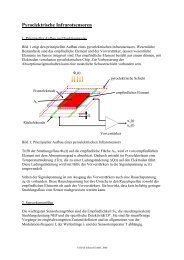
5 Camera System<br />
The camera system PYROLINE <str<strong>on</strong>g>256</str<strong>on</strong>g> was developed for use <str<strong>on</strong>g>with</str<strong>on</strong>g> pyroelectric linear <str<strong>on</strong>g>256</str<strong>on</strong>g>-elementarrays<br />
<str<strong>on</strong>g>256</str<strong>on</strong>g>-LT-I. Fig. 9 shows the complete camera. It c<strong>on</strong>sists of a robust, industrial housing that can<br />
be equipped <str<strong>on</strong>g>with</str<strong>on</strong>g> integrated water-cooling and air purge for lens system. The camera includes the pyroelectric<br />
array, a chopper module (chopper frequency 545 Hz), the IR-optics as well as the entire<br />
analog and digital signal processing.<br />
Fig. 9: Infrared line camera PYROLINE <str<strong>on</strong>g>256</str<strong>on</strong>g>
DIAS Infrared GmbH – Publicati<strong>on</strong>s – No. 15 7<br />
Four basic device variati<strong>on</strong>s for different applicati<strong>on</strong>s were developed. Essential technical data are<br />
summarized in Table 3. The standard temperature ranges include temperatures of 50–1300 ºC. Spectral<br />
ranges are 8–14 µm for low-temperature applicati<strong>on</strong>s, 3–5 µm for measurement of medium temperatures,<br />
4.8–5.2 µm for glass applicati<strong>on</strong>s and 1.4–1.8 µm for high temperature measurements.<br />
Table 3: Selected technical data of the line camera PYROLINE <str<strong>on</strong>g>256</str<strong>on</strong>g><br />
PYROLINE <str<strong>on</strong>g>256</str<strong>on</strong>g> <str<strong>on</strong>g>256</str<strong>on</strong>g> M <str<strong>on</strong>g>256</str<strong>on</strong>g> G <str<strong>on</strong>g>256</str<strong>on</strong>g> H<br />
Spectral range 8–14 µm 3–5 µm 4.8–5.2 µm 1.4–1.8 µm<br />
Measurement<br />
temperature range a<br />
50–550 °C / 450–1250 °C 450–1250 °C 450–1250 °C 600–1300 °C<br />
Aperture 40° x 0.3° 60° x 0.5° 60° x 0.5° 60° x 0.5°<br />
Spatial resoluti<strong>on</strong><br />
(50 % modulati<strong>on</strong>)<br />
3 mrad 4 mrad 4 mrad 4 mrad<br />
Measurement distance 10 cm – infinity 20 cm – infinity 20 cm – infinity 50 cm – infinity<br />
Accuracy b<br />
2 K up to 100 °C or<br />
1 K + 1 % of true value<br />
1 K + 1 % of true<br />
value<br />
1 K + 1 % of<br />
true value<br />
Frame rate internal 544 Hz, selectable 272 Hz, 136 Hz, ...<br />
Resp<strong>on</strong>se time internal 4 ms, selectable: 2/ measurement frequency<br />
Interface PCI-PC-card, fiber optic c<strong>on</strong>necti<strong>on</strong><br />
C<strong>on</strong>nectors c<br />
round c<strong>on</strong>nector <str<strong>on</strong>g>with</str<strong>on</strong>g> thread interlocking (16-pins)<br />
interlocking fiber optic- c<strong>on</strong>nector (2-fibers)<br />
water supply tubing (nominal width 4 mm, 2 bar max)<br />
compressed air tubing (nominal width 4 mm, 2 bar max)<br />
Housing IP65, opti<strong>on</strong>al <str<strong>on</strong>g>with</str<strong>on</strong>g> integrated water cooling system, air purge, swivel base<br />
Weight ca. 3.2 kg<br />
Supply voltage 18–36 V DC / 10–20 VA<br />
Operating temperature Camera: 0–50 °C, –25–150 °C (<str<strong>on</strong>g>with</str<strong>on</strong>g> water cooling)<br />
system cable: –25–150 °C<br />
fiber optic: 0–70 °C<br />
Storage c<strong>on</strong>diti<strong>on</strong> –20–70 °C, relative humidity 95 % max<br />
Software computer c<strong>on</strong>trol and display program for Windows<br />
a different <strong>on</strong> request,<br />
b for black body and ambient temperature 25 °C,<br />
c depending <strong>on</strong> c<strong>on</strong>figurati<strong>on</strong><br />
1 K + 1 % of<br />
true value<br />
Figure 10 shows the block diagram of this camera. The signal processing electr<strong>on</strong>ics includes:<br />
• Close to sensor electr<strong>on</strong>ics<br />
• Digital clock pulse generator<br />
• Analog-to-digital c<strong>on</strong>verter<br />
• Image difference processing (IDP)<br />
• Chopper motor c<strong>on</strong>troller<br />
• Sensor temperature stabilizati<strong>on</strong><br />
• Printed circuit board for signal input and output<br />
• DC/DC- printed circuit board<br />
Operati<strong>on</strong> of the camera, image acquisiti<strong>on</strong> and data processor are c<strong>on</strong>trolled using the “IR_LINE”<br />
software, which communicates <str<strong>on</strong>g>with</str<strong>on</strong>g> the camera via a dedicated PCI card and fiber-optic cable.
DIAS Infrared GmbH – Publicati<strong>on</strong>s – No. 15 8<br />
infrared<br />
radiati<strong>on</strong><br />
optic<br />
camera head<br />
TE-cooler<br />
Sensor<br />
clock driver<br />
6 Acknowledgements<br />
cooler/chopper pcb fiber pcb<br />
chopper<br />
c<strong>on</strong>troller<br />
sensor PCB<br />
pre-amplifier<br />
DC supply<br />
temperature<br />
sensors<br />
digital PCB<br />
ADC<br />
clock generator<br />
IDP<br />
DC/filter pcb<br />
power supply<br />
fiber optic<br />
driver<br />
serializer<br />
microc<strong>on</strong>troller<br />
digital<br />
input/output<br />
Fig. 10: Block diagram of the camera electr<strong>on</strong>ic PYROLINE <str<strong>on</strong>g>256</str<strong>on</strong>g> [8]<br />
to PC<br />
to process<br />
This work was supported by the Federal Ministry of Educati<strong>on</strong>, Science, Research and Technology<br />
(BMBF) under c<strong>on</strong>tracts № 16SV1094/0 and № 16SV1095/2.<br />
References<br />
[1] T. Sokoll, V. Norkus, G. Gerlach, “Thermal and Spatial Resoluti<strong>on</strong> of Pyroelectric <str<strong>on</strong>g>Linear</str<strong>on</strong>g> <str<strong>on</strong>g>Arrays</str<strong>on</strong>g>”,<br />
Proc. 3rd THERMINIC workshop, Cannes, pp. 217-222, 1997<br />
[2] V. Norkus, G. Gerlach, G. Hofmann, “Uncooled linear arrays <str<strong>on</strong>g>based</str<strong>on</strong>g> <strong>on</strong> LiTaO3”, Proc. of 9 th Int’l<br />
C<strong>on</strong>ference for Sensors, Transducers & Systems, Nürnberg, pp. 23-28, May 18-20, 1999<br />
[3] V. Norkus, G. Gerlach, G. Hofmann, “High-resoluti<strong>on</strong> infrared detectors <str<strong>on</strong>g>based</str<strong>on</strong>g> <strong>on</strong> LiTaO3”, Proc.<br />
of 3 rd OPTO C<strong>on</strong>ference, Erfurt, pp. 23-28, May 18-20, 1998<br />
[4] V. Norkus, T. Sokoll, G. Gerlach, G. Hofmann, “Pyroelectric infrared arrays and their applicati<strong>on</strong>s”,<br />
SPIE Infrared Spaceborne Remote Sensing V, Vol. 3122, pp. 409-419, 1997<br />
[5] F. Nagel, M. Zimmerhackl, “Spectrometer assembly <str<strong>on</strong>g>with</str<strong>on</strong>g> a pyroelectric array”, 5 th c<strong>on</strong>ference<br />
“Infrared Sensors and Systems”, Dresden, Dresdner Beiträge zur Sensorik, vol. 4, pp. 113-117,<br />
1997<br />
[6] V. Norkus, G. Gerlach, G. Hofmann, “Process Technologies for High-Resoluti<strong>on</strong> Infrared Detetors<br />
<str<strong>on</strong>g>based</str<strong>on</strong>g> <strong>on</strong> LiTaO3”, Device and Process Technologies for MEMS and Microelectr<strong>on</strong>ics, Proc.<br />
of SPIE, vol. 3892, Brisbane, pp. 233-240, 1999<br />
[7] V. Norkus, G. Gerlach, and G. Hofmann, “High-resoluti<strong>on</strong> pyroelectric linear arrays <str<strong>on</strong>g>based</str<strong>on</strong>g> <strong>on</strong><br />
LiTaO3“, SPIE 4369, pp. 322-331, 2001<br />
[8] P. Drögmöller, G. Hofmann, H. Budzier, Th. Reichardt, M. Zimmerhackl, “Infrared line cameras<br />
<str<strong>on</strong>g>based</str<strong>on</strong>g> <strong>on</strong> linear arrays for industrial temperature measurement“, to be published in SPIE Thermosense,<br />
Orlando, April 2002