DeltaV SIS with Electronic Marshalling
DeltaV SIS with Electronic Marshalling - Emerson Process ...
DeltaV SIS with Electronic Marshalling - Emerson Process ...

You also want an ePaper? Increase the reach of your titles
YUMPU automatically turns print PDFs into web optimized ePapers that Google loves.
<strong>DeltaV</strong> <strong>SIS</strong> Process Safety System<br />
<strong>DeltaV</strong> <strong>SIS</strong> <strong>with</strong> <strong>Electronic</strong> <strong>Marshalling</strong><br />
Product Data Sheet<br />
July 2015<br />
• Optimized process reliability.<br />
• Simplified safety lifecycle management.<br />
• Flexibility to meet project needs.<br />
• I/O Anywhere you need it.<br />
• Reduces installed cost of system.<br />
• Field mounted capable hardware.<br />
Introduction<br />
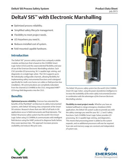
The <strong>DeltaV</strong> <strong>SIS</strong> process safety system has a uniquely scalable<br />
modular architecture that is based on the CHARMs Smart<br />
Logic Solver (CSLS) and the unprecedented flexibility and ease<br />
of use of the Emerson <strong>Electronic</strong> <strong>Marshalling</strong> solution. Each<br />
CSLS provides I/O processing, SIL 3-capable logic solving, and<br />
diagnostics in a single logic solver. The CSLS supports up to<br />
96 individually configurable channels, allowing flexibility for<br />
implementing safety instrumented functions and is designed<br />
specifically for multi-core home run cables or field junction box<br />
installation. All communications are completely redundant<br />
from the channel (LS CHARM) to the CSLS. Integrated HART ®<br />
I/O brings field diagnostics into the CSLS.<br />
Benefits<br />
Optimized process reliability. Emerson has extended the<br />
benefits of the PlantWeb ® architecture to safety instrumented<br />
systems, <strong>with</strong> <strong>DeltaV</strong> <strong>SIS</strong> being a key component of the Smart<br />
<strong>SIS</strong> solution. Research shows that over 90% of all faults in <strong>SIS</strong><br />
applications occur in field instruments and final elements. The<br />
<strong>DeltaV</strong> <strong>SIS</strong> process safety system has the world’s first Smart<br />
Logic Solver using LS CHARMs.It communicates <strong>with</strong> intelligent<br />
field devices using the HART protocol to diagnose faults before<br />
they cause spurious trips. This approach increases process<br />
availability and reduces lifecycle costs.<br />
The <strong>DeltaV</strong> <strong>SIS</strong> process safety system has the world’s first CHARMs<br />
Smart <strong>SIS</strong> Logic Solver, using the power of predictive intelligence to<br />
increase the availability of the entire safety instrumented function<br />
in combination <strong>with</strong> the advantages of the Emerson <strong>Electronic</strong><br />
<strong>Marshalling</strong> solution.<br />
Flexibility to meet project needs. Whether you have an<br />
isolated wellhead or a large emergency shutdown (ESD)<br />
application, the <strong>DeltaV</strong> <strong>SIS</strong> system scales to provide you <strong>with</strong><br />
the safety coverage you need for your SIL 1, 2 and 3 safety<br />
functions. Each CHARMs Smart Logic Solver provides I/O<br />
processing, SIL 3-capable logic solving, and diagnostics.<br />
This means that processing power is added as the system<br />
expands, and no additional processors will ever be required.<br />
Scan rate and memory usage are constant and independent<br />
of system size.
<strong>DeltaV</strong> <strong>SIS</strong> <strong>with</strong> <strong>Electronic</strong> <strong>Marshalling</strong><br />
July 2015<br />
Modularity also provides isolation of safety instrumented<br />
functions (SIFs). This isolation eliminates single-points of<br />
failure for improved availability and safety integrity.<br />
The <strong>DeltaV</strong> <strong>SIS</strong> system looks for new hardware every scan,<br />
so equipment can be added to a running system in real<br />
time. Online addition of new logic solvers will not interrupt<br />
your process.<br />
Simplified safety lifecycle management. The <strong>DeltaV</strong><br />
<strong>SIS</strong> CSLS’s are SIL 3-rated for both simplex and redundant<br />
architectures. Redundant pairs of CSLS’s can be installed<br />
for increased process availability of your SIFs.<br />
I/O anywhere you need it. The <strong>DeltaV</strong> <strong>SIS</strong> CSLS provides an<br />
unprecedented flexibility in safety system I/O topology. Using<br />
standard Ethernet infrastructure hardware you can add safety<br />
related I/O anywhere you need it. From a local I/O cabinet to<br />
remote enclosures miles away, simply install the CSLS and<br />
connect it to the Local Safety Network (LSN). Each CSLS can<br />
read the input signals from any other CSLS on the same LSN<br />
every 50 ms, the same as the inputs wired directly to its own<br />
LS CHARM system.<br />
Reduces installed cost of system. <strong>DeltaV</strong> <strong>SIS</strong> <strong>Electronic</strong><br />
<strong>Marshalling</strong> helps reduce overall system costs by eliminating<br />
internal cabinet cross wiring, reducing overall footprint,<br />
simplifying SIF design, and reducing FAT activities. <strong>Electronic</strong><br />
<strong>Marshalling</strong> provides separation between I&E hardware<br />
installation schedules and SIF development. Wiring can begin<br />
earlier knowing any late changes can be done <strong>with</strong>out lifting<br />
a wire. The ability to read any input on the LSN allows more<br />
efficient cabinet designs and accommodates late scope changes<br />
to add I/O anywhere. Adding additional SIF capacity does not<br />
require re-wiring I/O. Simply read the I/O signals from the<br />
proper CSLS, <strong>with</strong>out lifting a wire.<br />
Fully redundant communications. The CSLS architecture is<br />
fully redundant. It starts <strong>with</strong> the two logic solvers on a carrier.<br />
The carrier has redundant Safety Nework Ports (SNPs) for<br />
communication <strong>with</strong> primary and secondary LSN connections.<br />
There are two 24 VDC input power connections. The carrier<br />
connects to the CHARMs base plates providing redundant<br />
power and communication buses to the LS CHARMs. If required<br />
for availability you have the option to use redundant output LS<br />
CHARM Terminal Blocks <strong>with</strong> or <strong>with</strong>out internal 1 A relays for<br />
both DTA and ETA service. Everything is redundant down to the<br />
individual channel.<br />
Field mounted capable hardware. All components of the CSLS<br />
are rated for installation in Class 1/Div 2 or Zone 2 hazardous<br />
locations. The extended operating temperature ranges and G3<br />
environment rating allows them to be installed in field mounted<br />
junction boxes. This further reduces the footprint required in<br />
central equipment rooms, as well as reduces the overall wiring<br />
infrastructure of traditional multi-core instrumentation cable.<br />
Plug and Play I/O. The <strong>DeltaV</strong> <strong>SIS</strong> CSLS has been designed<br />
for ease of use, both in physical installation and its software<br />
tools. Components snap together <strong>with</strong> secure DIN-rail latches<br />
and interlocking carrier connectors. Attach a series of 96 I/O<br />
channels to a DIN-rail in a matter of minutes. Insert the LS<br />
CHARMs and auto sense the node to create the I/O definition<br />
automatically in your <strong>DeltaV</strong> <strong>SIS</strong> configuration database. LS<br />
CHARMs use a self keying system to automatically set a channel<br />
for a specific LS CHARM type. Users cannot mistakenly insert a<br />
LS CHARM into the wrong terminal block.<br />
Field power is provided through a redundant 24VDC bus to each<br />
LS CHARM, <strong>with</strong> up to 100 mA per LS CHARM. Higher current<br />
Discrete Input Channels can be powered through integrated<br />
power injection bus local to each CHARM Base plate. LS Discrete<br />
Output terminal blocks <strong>with</strong> integrated relays are also available<br />
for up to 1A continuous load.<br />
Product Description<br />
For Use in SIL 3 Applications<br />
With a safe failure fraction (SFF) greater than 99%, both simplex<br />
and redundant installations of the <strong>DeltaV</strong> <strong>SIS</strong> CSLS meet the SIL<br />
3 requirements of IEC 61508 <strong>with</strong> no restrictions. Redundant<br />
CSLS’s increase availability, but because both simplex and<br />
redundant CSLS’s provide hardware fault tolerance and safe<br />
failure fraction to meet SIL 3 requirements, redundancy does<br />
not increase safety.<br />
SIF-based Approach<br />
The <strong>DeltaV</strong> <strong>SIS</strong> system design was based on IEC 61511 safety<br />
instrumented function (SIF) concept, where every logic solver<br />
is a container for a small number of SIFs. Unlike other system<br />
architectures, <strong>with</strong> modular logic solving architecture, the logic<br />
solver is no longer a single point of failure for the entire process.<br />
If failures were to occur, only the equipment tied to the logic<br />
solver would be affected.<br />
www.emersonprocess.com 2
<strong>DeltaV</strong> <strong>SIS</strong> <strong>with</strong> <strong>Electronic</strong> <strong>Marshalling</strong><br />
July 2015<br />
The <strong>DeltaV</strong> <strong>SIS</strong> SIF-based approach does not mean that all<br />
of the safety logic and I/O have to fit into one logic solver.<br />
All input data is made available to every logic Solver on the<br />
Local Safety Network every 50ms the same as the local inputs<br />
on every CSLS.<br />
With <strong>DeltaV</strong> <strong>SIS</strong> logic solvers, neither the scan rate nor<br />
the execution of a SIF is altered by changes or additions<br />
to another SIF. <strong>DeltaV</strong> <strong>SIS</strong> logic solvers always execute<br />
deterministically, every 50 ms, regardless of how much<br />
I/O is running on the system.<br />
Redundancy<br />
The redundant logic solvers include two CSLS’s installed sideby-side<br />
on the CSLS Carrier. The CSLS Carrier has redundant<br />
power and communication connections to the base plates that<br />
are wired to the field devices. Each CSLS of the redundant pair<br />
has a separate power supply.<br />
No control strategy configuration is required to take advantage<br />
of CSLS redundancy because the <strong>DeltaV</strong> <strong>SIS</strong> auto-sense<br />
capability automatically recognizes the redundant pair of cards.<br />
When redundancy is chosen, the two CSLS’s run in parallel<br />
at all times. Both read the inputs from the I/O terminals,<br />
both execute the logic and both drive the outputs at the<br />
I/O terminals. There is no concept of primary and backup<br />
or master and slave, which is unlike any other safety system.<br />
The only difference between the two CSLS’s is that one<br />
communicates <strong>with</strong> the engineering and operator workstations<br />
as well as the dedicated local safety network (LSN). This<br />
CSLS has the Active light illuminated. The other CSLS is<br />
communicating only <strong>with</strong> the LSN.<br />
Logic Solver Switchover<br />
In the event that a failure is detected in one of the CSLS’s,<br />
the CSLS will automatically will go into a failed state. In this<br />
condition, there is no impact to the partner CSLS or the physical<br />
outputs. The partner CSLS continues to read inputs, execute<br />
logic and drive outputs. The transition from redundant to<br />
simplex is completely bumpless.<br />
Both logic solvers in a redundant pair are monitored for<br />
integrity alarms at all times, and an integrity error in either<br />
CSLS will notify the operator of a failure. Events that can cause<br />
integrity alarms include:<br />
• Hardware failure <strong>with</strong>in a logic solver<br />
• Communications failure between a logic solver and the LSN<br />
• Communications failure between a redundant pair of<br />
logic solvers<br />
• Removal of a logic solver from the carrier<br />
The health and status of both logic solvers and their<br />
channels are available in the Diagnostics Explorer.<br />
When one CSLS of a redundant pair of logic solvers is removed<br />
online, there is no disturbance to the process. When the<br />
missing CSLS is replaced <strong>with</strong> another, the new CSLS completes<br />
its power-up self-tests before the active CSLS cross-loads the<br />
current database. In safe areas, failed CSLS’s can be replaced<br />
under power. In hazardous areas, appropriate installation<br />
procedures must be followed.<br />
Online proof testing<br />
Online proof testing can be performed on a redundant<br />
pair of logic solvers. The desired proof-test interval is set in<br />
the configuration. The logic solvers perform the proof test<br />
automatically, <strong>with</strong> a warning provided to the operator before<br />
the automatic proof test is started.<br />
Diagnostics<br />
The <strong>DeltaV</strong> <strong>SIS</strong> logic solvers execute extensive self-testing on a<br />
continuous basis to detect potential faults. Faults detected by<br />
logic solver diagnostics can be associated <strong>with</strong> the logic solver<br />
itself or associated <strong>with</strong> field devices, field wiring, or other<br />
conditions not related to hardware.<br />
<strong>DeltaV</strong> <strong>SIS</strong> provides standard alarms to annunciate faults<br />
detected by logic solvers in the operator interface. No special<br />
configuration is required. When a diagnostic alarm occurs, it<br />
appears on the alarm banner of the operator interface. The<br />
operator is shown the type of alarm (failed, maintenance, etc.),<br />
as well as text for the active condition or “Multiple conditions” if<br />
more than one alert condition is active for the particular alarm.<br />
Sequence of Events Capability<br />
With <strong>DeltaV</strong> <strong>SIS</strong>, events are automatically generated as function<br />
blocks are executed <strong>with</strong>in a module scan. Events are time<br />
stamped <strong>with</strong> a resolution of
<strong>DeltaV</strong> <strong>SIS</strong> <strong>with</strong> <strong>Electronic</strong> <strong>Marshalling</strong><br />
July 2015<br />
In general, when there is a plant event that triggers an<br />
emergency shutdown from the <strong>SIS</strong>, one input will exceed a trip<br />
limit on one scan and this will cause outputs to trip and more<br />
inputs will then change state. Sequence of Events Recording has<br />
been used to find that first input that caused the trip by looking<br />
at all of the inputs in the plant. With the <strong>DeltaV</strong> <strong>SIS</strong> system, the<br />
operator simply filters the Event Chronicle for first out trips, and<br />
the first-out is clearly visible.<br />
If higher resolution is required for some channels then they can<br />
be wired to both the <strong>DeltaV</strong> <strong>SIS</strong> Logic Solver and also to a <strong>DeltaV</strong><br />
Discrete Input Card for Sequence of Events, which provides a<br />
resolution of 0.25 ms.<br />
Integrated HART<br />
Integrated HART I/O brings field diagnostics into the logic<br />
solver. Field device diagnostics information is not just for<br />
pass-through to AMS Device Manager; it is available inside<br />
the logic solver.<br />
The <strong>DeltaV</strong> <strong>SIS</strong> logic solver can also generate HART commands<br />
to initiate a partial stroke test in a digital valve controller. The<br />
operators can initiate partial stroke tests manually from their<br />
operator workstations or they can be scheduled to occur<br />
automatically based on the specified test interval. The results<br />
from these tests are captured and integrated <strong>with</strong> the system<br />
event history. An alarm can be generated if a partial stroke test<br />
fails, alerting maintenance that there is a potential problem<br />
<strong>with</strong> a valve.<br />
<strong>DeltaV</strong> <strong>SIS</strong> <strong>Electronic</strong> <strong>Marshalling</strong><br />
hardware includes:<br />
• CHARM Smart Logic Solver Carrier (DIN rail mounted and<br />
supports a redundant pair of CHARM Smart Logic Solvers,<br />
redundant 24 VDC power connectivity, and redundant<br />
Ethernet Safety Network communication Ports)<br />
• CHARM Smart Logic Solver (provides redundant safety logic<br />
processing and communication to up to 96 LS-CHARMs<br />
• CHARM Base plate (DIN rail mounted <strong>with</strong> interleaving<br />
power and bus connectors. Supports 12 LS CHARMS and<br />
their terminal blocks, as well as connection for injected<br />
field power)<br />
• LS CHARM Terminal Block (removable terminal block<br />
providing terminal connections to field wiring and<br />
physical latch for LS-CHARM)<br />
• LS CHARMs (Logic Solver Characterization Module for each<br />
field signal. Provides basic analog to digital conversion and<br />
signal isolation to the redundant communication bus)<br />
• Cable Extenders that provide flexibility in carrier mounting.<br />
• I/O bus termination (provides bus terminations for<br />
redundant I/O bus)<br />
• Labeling features for base plate and channel identification.<br />
The CHARM Smart Logic Solver carrier is mounted to the top<br />
of a vertical DIN rail and up to eight CHARM Base plates are<br />
mounted below it, snapping easily to the DIN rail as they are<br />
connected to each other. The bus termination assembly is<br />
attached at the bottom. A standard DIN-rail lock is used to<br />
keep the entire assembly in place.<br />
A pair of CHARM Smart Logic solvers installs on the carrier<br />
and communicates over a redundant Ethernet safety network<br />
<strong>with</strong> up to 15 other CSLS’s and 1 SZ controller, allowing great<br />
flexibility and ease of system expansion. Safety Network Ports<br />
are available for copper only.<br />
Only <strong>DeltaV</strong> <strong>SIS</strong> Smart Switches are supported on the Local<br />
Safety Network.<br />
Each baseplate is ordered <strong>with</strong> 12 terminal blocks: standard<br />
terminal blocks or fused injected power terminal blocks.<br />
<strong>Electronic</strong> <strong>Marshalling</strong> eliminates the need to partition the I/O<br />
wiring to specific channels based on signal type. Simply connect<br />
field signal multi-cores in an orderly fashion as desired. Install<br />
the appropriate LS CHARM to complete the field circuit and the<br />
signal is ready to be used by the CSLS. No cross-wiring required.<br />
Each LS CHARM acts as a circuit protection device and field<br />
wiring disconnect. Signals are inherently current limited<br />
to protect against wiring faults to ground. Each LS CHARM<br />
provides surge protection to meet industry standards in the<br />
area of EMC. Under extreme overvoltage conditions due to<br />
incorrect field wiring, the LS CHARM will act as a fuse to protect<br />
adjacent channels. Signal faults are thus isolated to the single<br />
LS CHARM.<br />
LS CHARMs can be partially ejected to a locked position that<br />
disconnects the field wiring from the system to perform field<br />
maintenance actions or to remove power to a field device.<br />
Activating the LS CHARM latch ejects the LS CHARM to the<br />
detent position. Closing the latch locks the LS CHARM in place<br />
and isolates the field wiring for field work.<br />
Baseplate extenders and cables provide great flexibility to the LS<br />
CHARM installation in existing cabinets or in custom enclosures.<br />
Cables are redundant, each carrying 24 VDC field power, 6.3<br />
VDC LS-CHARM power and one of the communication busses.<br />
Bus termination provides added robustness for the<br />
communication bus and is installed at the end of the<br />
physical bus.<br />
www.emersonprocess.com 4
<strong>DeltaV</strong> <strong>SIS</strong> <strong>with</strong> <strong>Electronic</strong> <strong>Marshalling</strong><br />
July 2015<br />
Label features are available to identify channel usage and<br />
Baseplate identification to help <strong>with</strong> maintenance.<br />
LS CHARMs can be added to any existing base plate position<br />
and autosensed online. Additional CSLS’s can be added online.<br />
LS CHARM Types<br />
A variety of analog and discrete LS CHARMs are available to<br />
meet your specific requirements. The following LS CHARMs<br />
are available starting <strong>with</strong> v12.3:<br />
• LS AI 4-20 mA HART<br />
• LS RTD<br />
• LS Thermocouple / mV<br />
• LS AI 0-10 VDC Isolated<br />
• LS DI NAMUR<br />
• LS DI 24 VDC low-side sense (dry contact)<br />
• LS DI 24 VDC Isolated<br />
• LS 24 VDC Power<br />
• LS DO 24 VDC DTA<br />
• LS DO 24 VDC ETA<br />
• LS DVC HART DTA<br />
• LS DO 24 VDC Redundant DTA<br />
• LS DO 24 VDC Redundant ETA<br />
• LS DVC HART Redundant DTA<br />
• LS DI 120 VAC Isolated<br />
• LS DI 230 VAC Isolated<br />
All LS CHARMs have a bi-color Power/Integrity LED that<br />
indicates the health of the LS CHARM. The indications provide<br />
clear, actionable instruction to the maintenance personnel.<br />
Green Solid: Normal Operation<br />
Green Blink: Normal awaiting configuration<br />
Red Blink: Fault detected on wiring<br />
Red Solid: Internal Fault detected<br />
Discrete LS CHARMs have a Yellow LED to indicate the state of<br />
the field signal. (On = circuit is energized)<br />
All LS CHARMs meet ISA 71.04-1985 severity level G3 (harsh)<br />
corrosion specifications.<br />
I/O Terminal Block Options<br />
There are 9 different I/O terminal blocks available to meet the<br />
wiring needs of field signals.<br />
• Standard Terminal Block<br />
• Fused Injected Power Terminal Block<br />
• 3-wire DI Fused Injected Power Terminal Block<br />
• Thermocouple / mV Terminal Block<br />
• LS DVC Terminal Block<br />
• LS Redundant Terminal Block<br />
• LS Redundant DTA Fused Injected Power Relay Terminal Block<br />
• LS Redundant DTA Relay Terminal Block<br />
• LS Redundant ETA Relay Terminal Block<br />
• LS Redundant DVC Terminal Block<br />
The Standard Terminal Block can be used <strong>with</strong> all LS AI,<br />
DI, and RTD CHARMs types. For traditional wiring of field<br />
instrumentation, the LS CHARMs provide loop power through<br />
the internally distributed 24 VDC field power. Refer to specific LS<br />
CHARM specifications for wiring information.<br />
Both, the Fused Injected Power Terminal block as well the<br />
3-wire DI Fused Injected Power Terminal block includes a<br />
2A field replaceable fuse. The 3-wire DI Fused Injected Power<br />
Terminal block is designed to be used <strong>with</strong> all Isolated discrete<br />
Input CHARM types, while the Fused Injected Power Terminal<br />
block is designed to work <strong>with</strong> the LS 24 VDC Power CHARM,<br />
creating a system powered circuit that can deliver up to 1 amp<br />
(DC) to the field. Each baseplate has a local power bus that can<br />
be connected to 24 VDC or 120/230 VAC through the injected<br />
power input terminals, located on the Address Plug terminal<br />
block. Fused Injected power Terminal Blocks connect to<br />
this power bus to provide system power to the field circuit<br />
through the isolated LS CHARM. You can combine isolated<br />
and system powered circuits on the same base-plate, however,<br />
all system powered channels on a base- plate share the same<br />
power source.<br />
The Thermocouple / mV Terminal Block is specially designed<br />
for the usage <strong>with</strong> the LS Thermocouple / mV CHARM. The<br />
Thermocouple / mV Terminal Block has fixed key positions to<br />
prevent a mismatch in the field and can only be ordered as an<br />
Assembly <strong>with</strong> the LS Thermocouple / mV CHARM.<br />
The LS DVC Terminal Block can be used <strong>with</strong> the LS DVC HART<br />
DTA CHARM type. Refer to specific LS CHARM specifications for<br />
wiring information.<br />
www.emersonprocess.com 5
<strong>DeltaV</strong> <strong>SIS</strong> <strong>with</strong> <strong>Electronic</strong> <strong>Marshalling</strong><br />
July 2015<br />
The LS Redundant Terminal Block can be used <strong>with</strong> the<br />
Redundant DVC Output LS CHARM typse. Refer to specific LS<br />
CHARM specifications for wiring information.<br />
The LS Redundant DTA Fused Injected Power Terminal<br />
Blocks are designed for high output current applications and<br />
requires the LS DO 24 VDC Redundant DTA or ETA CHARM to<br />
drive the relay coil. The Redundant Relay Output Term blocks<br />
provide a normally open and normally closed contact <strong>with</strong> the<br />
following ratings:<br />
LS CHARM Keying Posts<br />
The Terminal Blocks contain keying posts that are automatically<br />
set and locked to the unique position of the installed LS<br />
CHARM. The keys prevent the insertion of an incorrect LS<br />
CHARM during maintenance activities. They are shipped in a<br />
neutral position and are set when a LS CHARM is inserted. If<br />
needed, the keys can be manually reset to allow a channel to<br />
be re-tasked for a different signal type.<br />
• 28.8 VDC at 1 A switching current<br />
• 48 VDC at 0.4 A switching current<br />
• 250 VAC at 1 A switching current<br />
The LS Redundant DTA Relay Terminal Block can be used <strong>with</strong><br />
the LS DO Redundant DTA CHARMs type. Refer to specific LS<br />
CHARM specifications for wiring information<br />
The LS Redundant ETA RelayTerminal Block can be used <strong>with</strong><br />
the LS DO Redundant ETA CHARMs type. Refer to specific LS<br />
CHARM specifications for wiring information<br />
The LS Redundant DVC Terminal Block can be used <strong>with</strong> the LS<br />
DVC HART Redundant DTA CHARMs Refer to specific LS CHARM<br />
specifications for wiring information type.<br />
Although any signal type can be installed in any location on the<br />
CHARM baseplates, it is recommended that AC voltage circuits<br />
be separated from low voltage signals to comply <strong>with</strong> safety<br />
recommendations and to mitigate induced noise in the signals.<br />
Standard Terminal blocks, Fused Injected Power terminal blocks<br />
LS Redundant DTA Fused Injected Power Terminal Blocks can<br />
be used on the same carrier, typically to allow the use of DO 24<br />
VDC isolated CHARMs on higher wattage devices along side of<br />
standard 24 VDC instrumentation signals or Relay contacts.<br />
LS CHARM Standard Terminal Block.<br />
The keying mechanism consists of two keying posts that rotate<br />
and lock into the terminal block base. Each LS CHARM type is<br />
assigned a unique key setting.<br />
The LS DVC Terminal Block, LS Redundant DTA Relay Terminal<br />
Block, LS Redundant ETA RelayTerminal Block and the LS<br />
Redundant DVC Terminal Block has fixed key positions to<br />
prevent a mismatch in the field.<br />
www.emersonprocess.com 6
<strong>DeltaV</strong> <strong>SIS</strong> <strong>with</strong> <strong>Electronic</strong> <strong>Marshalling</strong><br />
July 2015<br />
<strong>DeltaV</strong> <strong>SIS</strong> CSLS Capacities<br />
Item<br />
Limit<br />
Maximum number of CSLSs on a single SZ Controller 16<br />
Maximum number of Remote I/O Nodes (CIOCs and/or WIOCs) reporting to a single SZ Controller 4<br />
Maximum number of secure parameters per CSLS 96<br />
Maximum number of CSLS I/O channels on a single SZ Controller: 96 CHARMs I/O channels × 16 CSLS 1536<br />
Maximum number of CSLSs in a single <strong>DeltaV</strong> <strong>SIS</strong> system: 100 SZ controllers × 16 CSLS per SZ controller 1600<br />
Hardware Specifications<br />
Operating temperature<br />
Storage temperature<br />
Relative humidity<br />
Common Environmental Specifications (all components)<br />
-40 to 70°C (-40 to 158°F)<br />
-40 to 85°C (-40 to 185°F)<br />
5 to 95% , non-condensing<br />
Protection rating IP 20, NEMA 12<br />
Airborne contaminants<br />
Shock<br />
Vibration<br />
ISA-S71.04-1985 Airborne Contaminants Class G3<br />
Conformal coating<br />
10 g ½-sine wave for 11 ms<br />
1mm Peak-to-Peak from 2 to 13.2 Hz; 0.7g from 13.2 to 150 Hz<br />
www.emersonprocess.com 7
<strong>DeltaV</strong> <strong>SIS</strong> <strong>with</strong> <strong>Electronic</strong> <strong>Marshalling</strong><br />
July 2015<br />
SZ Controller shown on SZ Controller Carrier.<br />
SZ Controller Ethernet Isolation Port.<br />
www.emersonprocess.com 8
<strong>DeltaV</strong> <strong>SIS</strong> <strong>with</strong> <strong>Electronic</strong> <strong>Marshalling</strong><br />
July 2015<br />
SZ Controller shown on Dual Universal Safety Carrier.<br />
SZ Controller Ethernet Isolation Port.<br />
www.emersonprocess.com 9
<strong>DeltaV</strong> <strong>SIS</strong> <strong>with</strong> <strong>Electronic</strong> <strong>Marshalling</strong><br />
July 2015<br />
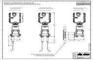
CSLS shown on CSLS Carrier.<br />
CSLS Safety Network Port.<br />
www.emersonprocess.com 10
<strong>DeltaV</strong> <strong>SIS</strong> <strong>with</strong> <strong>Electronic</strong> <strong>Marshalling</strong><br />
July 2015<br />
CHARM Baseplate <strong>with</strong> CHARMs terminal blocks.<br />
CHARM Baseplate Terminator Top.<br />
CHARM Baseplate Terminator Bottom.<br />
www.emersonprocess.com 11
<strong>DeltaV</strong> <strong>SIS</strong> <strong>with</strong> <strong>Electronic</strong> <strong>Marshalling</strong><br />
July 2015<br />
CHARM Baseplate Extender Top.<br />
CHARM Baseplate Extender Bottom.<br />
Input LS CHARMs.<br />
www.emersonprocess.com 12
<strong>DeltaV</strong> <strong>SIS</strong> <strong>with</strong> <strong>Electronic</strong> <strong>Marshalling</strong><br />
July 2015<br />
Output LS CHARMs.<br />
CHARM Standard Terminal Block.<br />
www.emersonprocess.com 13
<strong>DeltaV</strong> <strong>SIS</strong> <strong>with</strong> <strong>Electronic</strong> <strong>Marshalling</strong><br />
July 2015<br />
CHARM 3-wire DI Fused Injected Power Terminal Block.<br />
CHARM Fused Injected Power Terminal Block.<br />
CHARM Thermocouple / mV Terminal Block.<br />
www.emersonprocess.com 14
<strong>DeltaV</strong> <strong>SIS</strong> <strong>with</strong> <strong>Electronic</strong> <strong>Marshalling</strong><br />
July 2015<br />
LS CHARM DVC Terminal Block.<br />
LS CHARM Redundant Terminal Block.<br />
LS CHARM Redundant DTA Fused Injected Power Relay Terminal Block.<br />
www.emersonprocess.com 15
<strong>DeltaV</strong> <strong>SIS</strong> <strong>with</strong> <strong>Electronic</strong> <strong>Marshalling</strong><br />
July 2015<br />
LS CHARM Redundant DTA Relay Terminal Block.<br />
LS CHARM Redundant ETA Relay Terminal Block.<br />
LS CHARM Redundant DVCTerminal Block.<br />
www.emersonprocess.com 16
<strong>DeltaV</strong> <strong>SIS</strong> <strong>with</strong> <strong>Electronic</strong> <strong>Marshalling</strong><br />
July 2015<br />
SZ Controller Hardware<br />
Capacity<br />
Input power<br />
Battery power<br />
Specifications for SZ Controller and Dual Universal Safety Carrier<br />
One (simplex) or two (redundant) SZ Controllers<br />
+24 VDC ±10% at 1 A maximum<br />
+5.0 to +12.6 VDC at 30 uA typical<br />
Redundant Ethernet connections via replaceable<br />
Ethernet Isolation Ports (EIPs)<br />
SZ Controller Carrier Mounting<br />
Dual Universal Safety Carrier Mounting<br />
Copper twisted pair: 10/100BASE-TX <strong>with</strong> RJ45 connectors; Full duplex<br />
operation - 100 m distance<br />
DIN rail latch to vertical orientated T-type rail<br />
DIN rail latch to horizontaly orientated T-type rail<br />
Number of SZs per system 100<br />
Specifications for SZ Controller<br />
Input power<br />
Heat dissipation (redundant)<br />
Fuse Protection (internal)<br />
Mounting<br />
Communication<br />
LSN, ACN Network Addressing<br />
Modbus TCP Addressing<br />
+24 VDC ± 10% at 325 mA maximum for simplex;<br />
575 mA maximum for redundant<br />
7 Watts maximum for simplex; 13 Watts maximum for redundant<br />
Internal Non-replaceable Fuse<br />
One or two slots on the SZ Controller or Dual Universal Safety Carrier<br />
Redundant Ethernet connections via SZ Controller or Dual Universal Safety<br />
Carrier to the :<br />
a) Local Safety Network (LSN)<br />
b) Area Control Network (ACN) or Modbus TCP ports<br />
Auto Assigned during commissioning<br />
Manual, Slave only<br />
DST Limit 400<br />
Max data values sent<br />
Max data values received<br />
4000/second<br />
500/second<br />
Max unsolicited client nodes 120<br />
BPCS Module execution rates<br />
Green – Power<br />
Red – Error<br />
Green – Active/Standby<br />
Yellow flashing – Pri./Sec. CN<br />
100ms, 200ms, 500ms, 1s, 2s, 5s, 10s, 30s, 60s<br />
LED Indicators<br />
Indicates DC power is applied<br />
Indicates an error condition<br />
Indicates operating mode of each SZ<br />
Indicates valid control network communication<br />
www.emersonprocess.com 17
<strong>DeltaV</strong> <strong>SIS</strong> <strong>with</strong> <strong>Electronic</strong> <strong>Marshalling</strong><br />
July 2015<br />
CSLS Hardware<br />
Capacity<br />
Input power (redundant)<br />
Output power to <strong>SIS</strong> CHARMs<br />
Redundant Ethernet connections via replaceable<br />
Safety Network Ports (SNPs)<br />
Mounting<br />
Number of I/O Channels<br />
Specifications for CSLS Carrier<br />
One (simplex) or two (redundant) CSLS and one (simplex)<br />
or two (redundant) Power Modules<br />
+24 VDC ± 10% at 12.5 A maximum<br />
+24 VDC ± 10% at 10 A maximum<br />
+6.3 VDC at 4 A maximum<br />
Copper twisted pair: 10/100BASE-TX <strong>with</strong> RJ45 connectors;<br />
Full duplex operation - 100 m distance<br />
DIN rail latch to vertical orientated T-type rail<br />
Specifications for CSLS<br />
96 Channels, Individually defined signal types<br />
Number of CSLSs per SZ Controller 16<br />
Number of CSLSs per system 1600<br />
I/O update rates<br />
Power requirement of CSLS<br />
Power requirement of Power Modules<br />
Power Modules output to LS-CHARMs<br />
Heat dissipation per carrier <strong>with</strong> redundant<br />
CSLS pair<br />
Fuse Protection (internal)<br />
Mounting<br />
Communication<br />
Network Addressing<br />
Green – Power<br />
Red – Error<br />
Green – Active/Standby<br />
Yellow flashing – Pri./Sec. CN<br />
50ms<br />
+24 VDC ± 10% at 325 mA maximum for simplex;<br />
575 mA maximum for redundant (CHARMs are additional)<br />
+24 VDC ± 10% at 1.5 A maximum simplex and redundant<br />
+6.3 VDC ± 3% at 4 A maximum<br />
18 Watts maximum, which includes:<br />
- 13 Watts for redundant CSLS (7 Watts for simplex)<br />
- 3 Watts for redundant Power Modules<br />
- 1 Watt per Safety Network Port<br />
Internal Non-replaceable Fuse<br />
One or two slots on the CSLS Carrier<br />
Redundant Ethernet connections via CSLS Carrier to the<br />
Local Safety Network (LSN)<br />
Auto Assigned during commissioning<br />
LED Indicators<br />
Indicates DC power is applied<br />
Indicates an error condition<br />
Indicates operating mode of each CSLS<br />
Indicates valid control network communication<br />
www.emersonprocess.com 18
<strong>DeltaV</strong> <strong>SIS</strong> <strong>with</strong> <strong>Electronic</strong> <strong>Marshalling</strong><br />
July 2015<br />
CHARMs Baseplate Hardware<br />
Specifications for CHARMs Baseplate<br />
Number of channels per baseplate 12<br />
Number of baseplates per CSLS 8<br />
Addressing One Address Plug (1 through 8)<br />
Terminal blocks<br />
Shield connections<br />
Wire strip length<br />
Mounting<br />
Shield connections<br />
Wire strip length<br />
Standard Terminal Block<br />
3-wire DI Fused Injected Power Terminal Block<br />
Fused Injected Power Terminal Block<br />
Thermocouple / mV Terminal Block<br />
LS DVC Terminal Block<br />
LS Redundant Terminal Block<br />
LS Redundant DTA Fused Injected Power Relay Terminal Block<br />
LS Redundant DTA Relay Terminal Block<br />
LS Redundant ETA Relay Terminal Block<br />
LS Redundant DVC Terminal Block<br />
1 Screw Cage terminal per channel, plus 1 for cable shield<br />
0.32 – 2.5 mm2 / 22 – 14 AWG<br />
Gold plated connectors for shield continuity<br />
7 - 9 mm / 0.28 – 0.36 in.<br />
DIN rail Latch to T-type rail<br />
Specifications for Baseplate Termination, Top and Bottom<br />
2 Screw Cage Terminals<br />
0.32 – 2.5 mm2 / 22 - 14 AWG<br />
7 - 9 mm / 0.28 – 0.36 in.<br />
Primary Bus connection<br />
Secondary Bus connection<br />
Maximum bus length (including Base plates)<br />
Specifications for Baseplate Extenders, Top and Bottom<br />
9-pin D-shell,<br />
Primary RS-485 communications bus<br />
Primary 24 VDC field power<br />
Primary CHARM power<br />
9-pin D-shell,<br />
Secondary RS-485 communications bus<br />
Secondary 24 VDC field power<br />
Secondary CHARM power<br />
Specifications for Extender Cables<br />
5.5 m (18 ft)<br />
Available Cable lengths 2 m, 1 m, 0.5 m (6.7 ft, 3.3 ft, 1.6 ft )<br />
www.emersonprocess.com 19
<strong>DeltaV</strong> <strong>SIS</strong> <strong>with</strong> <strong>Electronic</strong> <strong>Marshalling</strong><br />
July 2015<br />
Number of connections<br />
Wire strip length<br />
Specifications for Standard Terminal Block<br />
4 Screw Cage terminals 0.32 – 2.5 mm2 / 22 – 14 AWG<br />
7 - 9 mm / 0.28 – 0.36 in.<br />
Maximum Current 2 A max. at 250 VAC max. *<br />
Color<br />
Number of connections<br />
Wire strip length<br />
Black<br />
Specifications for 3-wire DI Fused Injected Power Terminal Block<br />
3 Screw Cage terminals 0.32 – 2.5 mm2 / 22 – 14 AWG<br />
7 - 9 mm / 0.28 – 0.36 in.<br />
Maximum Current 1 A max. at 250 VAC max. *<br />
Field replaceable fuse<br />
Color<br />
Number of connections<br />
Wire strip length<br />
2 A<br />
Black<br />
Specifications for Fused Injected Power Terminal Block<br />
2 Screw Cage terminals 0.32 – 2.5 mm2 / 22 – 14 AWG<br />
7 - 9 mm / 0.28 – 0.36 in.<br />
Maximum Current 1 A max. at 250 VAC max. *<br />
Field replaceable fuse<br />
Color<br />
Number of connections<br />
Wire strip length<br />
Maximum Current<br />
Color<br />
Number of connections<br />
Wire strip length<br />
2 A<br />
Black<br />
Specifications for Thermocouple / mV Terminal Block<br />
2 Screw Cage terminals 0.32 – 2.5 mm2 / 22 – 14 AWG<br />
7 - 9 mm / 0.28 – 0.36 in.<br />
25 mA max. at 5 VDC max.<br />
Black<br />
Specifications for LS DVC Terminal Block<br />
2 Screw Cage terminals 0.32 – 2.5 mm2 / 22 – 14 AWG<br />
7 - 9 mm / 0.28 – 0.36 in.<br />
Maximum Current 30 mA max. at 30 VDC max. *<br />
Color<br />
Number of connections<br />
Wire strip length<br />
Black<br />
Specifications for LS Redundant Terminal Block<br />
2 Screw Cage terminals 0.32 – 2.5 mm2 / 22 – 14 AWG<br />
7 - 9 mm / 0.28 – 0.36 in.<br />
Maximum Current 2 A max. at 250 VAC max. *<br />
Color<br />
Black<br />
www.emersonprocess.com 20
<strong>DeltaV</strong> <strong>SIS</strong> <strong>with</strong> <strong>Electronic</strong> <strong>Marshalling</strong><br />
July 2015<br />
Number of connections<br />
Specifications for LS Redundant DTA Fused Injected Power Relay Terminal Block<br />
2 Screw Cage terminals 0.32 – 2.5 mm2 / 22 – 14 AWG<br />
Wire strip length<br />
Maximum Current<br />
Field replaceable fuse<br />
Color<br />
Number of connections<br />
Wire strip length<br />
Maximum Current<br />
Field replaceable fuse<br />
Color<br />
Number of connections<br />
Wire strip length<br />
Maximum Current<br />
Field replaceable fuse<br />
Color<br />
Number of connections<br />
Wire strip length<br />
7 - 9 mm / 0.28 – 0.36 in.<br />
1 A at 28.8 VDC / 0.4 A at 48 VDC / 1 A at 250 VAC<br />
2 A<br />
Black<br />
Specifications for LS Redundant DTA Relay Terminal Block<br />
2 Screw Cage terminals<br />
0.32 – 2.5 mm2 / 22 – 14 AWG<br />
7 - 9 mm / 0.28 – 0.36 in.<br />
1 A at 28.8 VDC / 0.4 A at 48 VDC / 1 A at 250 VAC<br />
2 A<br />
Black<br />
Specifications for LS Redundant ETA Relay Terminal Block<br />
2 Screw Cage terminals<br />
0.32 – 2.5 mm2 / 22 – 14 AWG<br />
7 - 9 mm / 0.28 – 0.36 in.<br />
1 A at 28.8 VDC / 0.4 A at 48 VDC / 1 A at 250 VAC<br />
2 A<br />
Black<br />
Specifications for LS Redundant DVC Terminal Block<br />
2 Screw Cage terminals<br />
0.32 – 2.5 mm2 / 22 – 14 AWG<br />
7 - 9 mm / 0.28 – 0.36 in.<br />
Maximum Current 60 mA max. at 30 VDC max. *<br />
Color<br />
Number of connections<br />
Wire strip length<br />
Black<br />
Specifications for Address Plug Terminal Block<br />
2 sets of 2 connections<br />
Screw Cage terminals<br />
0.32 – 2.5 mm2 / 22 – 14 AWG<br />
7 - 9 mm / 0.28 – 0.36 in.<br />
Maximum Current 10 A max. at 250 VAC max. **<br />
Color<br />
Black<br />
*Actual Current draw is determined by type of CHARM and associated field devices.<br />
**Maximum current draw of base plate is the sum of CHARMs installed <strong>with</strong> Injected Power Terminal block<br />
www.emersonprocess.com 21
<strong>DeltaV</strong> <strong>SIS</strong> <strong>with</strong> <strong>Electronic</strong> <strong>Marshalling</strong><br />
July 2015<br />
LS Analog Input 4-20 mA HART CHARM<br />
Sensor Types<br />
Nominal signal range (span)<br />
Full signal range<br />
Specifications for LS AI 4-20 mA HART CHARM<br />
4-20 mA <strong>with</strong> or <strong>with</strong>out HART<br />
0-20 mA<br />
Supports 2-wire and 4-wire device types directly<br />
Supports 3-wire device powered through the LS 24 VDC Power CHARM<br />
4-20 mA, (0-20 mA optional)<br />
0-24 mA<br />
Input impedance 250 ohms ±1%<br />
Field Power (2-wire)<br />
Accuracy over temperature range<br />
Safety Accuracy<br />
Repeatability<br />
Resolution<br />
Calibration<br />
DC/50/60 Hz Common mode rejection<br />
Field Circuit Protection<br />
CHARM power req.<br />
CHARM heat dissipation<br />
HART support<br />
HART data update rates<br />
15.0 V at 20 mA @ 24 VDC input<br />
0.1% of span (0 to 60°C)<br />
0.25% of span (over -40 to 70°C)<br />
2% of span<br />
0.05% of span<br />
16-bit A/D converter<br />
None required<br />
N/A<br />
- 30 mA Current Limiting circuit<br />
- Field wiring disconnect<br />
32 mA max @ 24 VDC for two wire configuration<br />
8 mA max @ 24 VDC for three and four wire configuration<br />
0.33 Watts<br />
HART v7 pass-through for AMS<br />
HART v7 variable and device status available to control<br />
500 ms<br />
Simplified Circuit and Connection Diagrams for LS AI HART CHARM 0/ 4 to 20 mA Two Wire and Four Wire transmitters.<br />
www.emersonprocess.com 22
<strong>DeltaV</strong> <strong>SIS</strong> <strong>with</strong> <strong>Electronic</strong> <strong>Marshalling</strong><br />
July 2015<br />
LS RTD Input CHARM<br />
Sensor types<br />
Sensor Configuration<br />
Full Scale signal range<br />
Accuracy<br />
Repeatability<br />
Resolution<br />
Calibration<br />
Sensor excitation current<br />
DC/50/60 Hz Common mode rejection<br />
Isolation<br />
Open sensor detection<br />
CHARM power req.<br />
CHARM Heat Dissipation<br />
Specifications for LS RTD CHARM<br />
RTD input (Types listed in Table)<br />
2 wire, 3 wire, or 4 wire<br />
See Table next page<br />
See Table next page<br />
0.05% of span<br />
24 Bit A/D converter / Depends upon the sensor type<br />
None required<br />
0.5 mA in 2-wire and 4 wire configurations<br />
0.25 mA in 3-wire<br />
90dB<br />
Each sensor galvanically isolated and factory tested to 1000 VDC<br />
Yes<br />
18 mA max @ 24 VDC<br />
0.30 Watts<br />
RTD, ohms Sensor Type Specifications<br />
Sensor Type Operating Range 25°Reference Accuracy Temperature Drift Resolution<br />
Pt100 -200 to 850°C ± 0.25°C ± 0.02°C/°C ~ 0.02°C<br />
Pt200 -200 to 850°C ± 0.25°C ± 0.02°C/°C ~ 0.02°C<br />
Pt500 -200 to 850°C ± 0.25°C ± 0.02°C/°C ~ 0.02°C<br />
Pt1000 -200 to 260°C ± 0.25°C ± 0.02°C/°C ~ 0.01°C<br />
Ni120 -80 to 260°C ± 0.15°C ± 0.01°C/°C ~ 0.01°C<br />
Ni100 -80 to 260°C ± 0.20°C ± 0.01°C/°C ~ 0.01°C<br />
Ni200 -80 to 260°C ± 0.20°C ± 0.01°C/°C ~ 0.01°C<br />
Ni500 -80 to 260°C ± 0.20°C ± 0.01°C/°C ~ 0.01°C<br />
Ni1000 -80to 140°C ± 0.20°C ± 0.01°C/°C ~ 0.01°C<br />
Cu10 -200 to 260°C ± 0.25°C ± 0.02°C/°C ~ 0.01°C<br />
Resistance/User Defined* 0 to 2,000 Ω ± 0.25 Ω ± 0.03 Ω/°C ~ 0.031 Ω<br />
* The Callendar-Van Dusen linearization equation can be used <strong>with</strong> user defined Pt RTDs.<br />
Refer to Recommended I/O Practices in <strong>DeltaV</strong> Books online for usage information.<br />
www.emersonprocess.com 23
<strong>DeltaV</strong> <strong>SIS</strong> <strong>with</strong> <strong>Electronic</strong> <strong>Marshalling</strong><br />
July 2015<br />
Simplified Circuit and Connection Diagrams for LS RTD CHARM.<br />
LS Thermocouple/mV Input CHARM<br />
Sensor types:<br />
Thermocouple<br />
mV<br />
Full Scale signal range<br />
Accuracy<br />
Repeatability<br />
Resolution<br />
Calibration<br />
Specifications for LS Thermocouple/mV Input CHARM<br />
B, E, J, K, N, R, S, T,<br />
Low level voltage source source (±20 mV, ±50 mV, and ±100 mV)<br />
See Table next page<br />
See Table next page<br />
0.05% of span<br />
24 Bit A/D converter / Depends upon the sensor type<br />
None required<br />
Cold junction compensation(CJC):<br />
Accuracy<br />
Range<br />
DC/50/60 Hz Common mode rejection<br />
Isolation<br />
Open sensor detection<br />
CHARM power req.<br />
CHARM Heat Dissipation<br />
± 1.0°C<br />
-40 to 85°C<br />
90dB<br />
Each sensor galvanically isolated and factory tested to 1000 VDC<br />
Yes<br />
18 mA max @ 24 VDC<br />
0.30 Watts<br />
www.emersonprocess.com 24
<strong>DeltaV</strong> <strong>SIS</strong> <strong>with</strong> <strong>Electronic</strong> <strong>Marshalling</strong><br />
July 2015<br />
Sensor Type<br />
25° Reference<br />
Accuracy 1<br />
Sensor Type Specifications<br />
Temperature Drift<br />
Nominal<br />
Resolution<br />
Full Scale<br />
Operating Range<br />
B ± 0.8°C ± 0.06°C/°C ~ 0.024°C 0 to 1820°C 250 to 1820°C<br />
E ± 0.4°C ± 0.03°C/°C ~ 0.018°C -270 to 1000°C -200 to 1000°C<br />
J ± 0.6°C ± 0.04°C/°C ~ 0.022°C -210 to 1200°C -210 to 1200°C<br />
K ± 0.4°C ± 0.03°C/°C ~ 0.025°C -270 to 1372°C -200 to 1372°C<br />
N ± 0.6°C ± 0.04°C/°C ~ 0.024°C -270 to 1300°C -200 to 1300°C<br />
R ± 0.8°C ± 0.05°C/°C ~ 0.028°C -50 to 1768°C -50 to 1768°C<br />
S ± 0.8°C ± 0.05°C/°C ~ 0.028°C -50 to 1768°C -50 to 1768°C<br />
T ± 0.5°C ± 0.02°C/°C ~ 0.01°C -270 to 400°C -250 to 400°C<br />
± 100 mV 0.025 mV ± 0.002 mV/°C ~ 0.0031 mV -100 to 100 mV -100 to 100 mV<br />
± 50 mV 0.020 mV ± 0.001 mV/°C ~ 0.0015 mV -50 to 50 mV -50 to 50 mV<br />
± 20 mV 0.010 mV ± 0.0005 mV/°C ~ 0.0006 mV -20 to 20 mV -20 to 20 mV<br />
1<br />
Total error is made up of the 25 C reference accuracy value, plus the CJC accuracy value, plus the sensor accuracy value<br />
Simplified Circuit and Connection Diagram for LS Thermocouple/mV CHARM <strong>with</strong><br />
Thermocouple/mV Terminal Block.<br />
www.emersonprocess.com 25
<strong>DeltaV</strong> <strong>SIS</strong> <strong>with</strong> <strong>Electronic</strong> <strong>Marshalling</strong><br />
July 2015<br />
LS Analog Input 0-10 VDC Isolated CHARM<br />
Sensor types<br />
Full Scale signal range<br />
Accuracy<br />
Input Impedance<br />
Repeatability<br />
Resolution<br />
Calibration<br />
Common mode rejection<br />
Isolation<br />
CHARM power req.<br />
CHARM Heat Dissipation<br />
Specifications for LS AI 0-10 VDC Isolated CHARM<br />
Voltage device<br />
See Table below<br />
See Table below<br />
10 MΩ<br />
0.05% of span<br />
24 bit A/D converter / Refer to the following table<br />
None required<br />
90dB at 50/60 Hz<br />
Input channel galvanically isolated and factory tested to 1000 VDC<br />
18 mA max @ 24 VDC<br />
0.40 Watts<br />
Isolated Input Voltage Sensor Type Specifications<br />
Sensor Type Sensor Range 25°Reference Accuracy Temperature Drift Nominal Resolution<br />
0 to 5 V 0 to 5 V ± 0.005 V ± 0.0005 V/°C 0.00008 V<br />
0 to 10 V 0 to 10 V ± 0.010 V ± 0.001 V/°C 0.00015 V<br />
1 to 5 V 1 to 5 V ± 0.005 V ± 0.0005 V/°C 0.00006 V<br />
1 V -1 to +1 V ± 0.0025 V ± 0.0002 V/°C 0.00003 V<br />
5 V -5 to +5 V ± 0.005 V ± 0.0005 V/°C 0.00015 V<br />
10 V -10 to +10 V ± 0.010 V ± 0.001 V/°C 0.00030 V<br />
Simplified Circuit and Connection Diagram for LS AI 0-10 VDC Isolated CHARM.<br />
Note: Installing a 250 Ω range resistor across terminals 3 and 4 converts a 4-20 mA field signal to 1-5V input signal<br />
www.emersonprocess.com 26
<strong>DeltaV</strong> <strong>SIS</strong> <strong>with</strong> <strong>Electronic</strong> <strong>Marshalling</strong><br />
July 2015<br />
LS Discrete Input NAMUR CHARM<br />
Sensor Types<br />
Detection level for On<br />
Detection level for Off<br />
Channel Impedance<br />
Specifications for LS DI NAMUR CHARM<br />
NAMUR Sensors, Dry Contacts, Dry contact <strong>with</strong> end of line resistance<br />
> 2.1 mA (9 kΩ)<br />
1.5 KW (approximate)<br />
Wetting Voltage 12 Volts (± 5%)<br />
Fault Detection capable<br />
Configurable channel types:<br />
• Discrete input<br />
Field Circuit Protection<br />
CHARM power req.<br />
CHARM Heat Dissipation<br />
NAMUR Sensors or field resistor pack<br />
• Guaranteed short circuit: 75 kΩ<br />
Dry contact or discrete state sensor changing
<strong>DeltaV</strong> <strong>SIS</strong> <strong>with</strong> <strong>Electronic</strong> <strong>Marshalling</strong><br />
July 2015<br />
LS Discrete Input 24 VDC low-side sense (dry contact) CHARM<br />
Sensor Types<br />
Detection level for On<br />
Detection level for Off<br />
Channel Impedance<br />
Wetting Voltage<br />
Fault Detection capable<br />
Configurable channel types:<br />
• Discrete input<br />
Field Circuit Protection<br />
CHARM power req.<br />
CHARM Heat Dissipation<br />
Specifications for LS DI 24 VDC low-side sense (dry contact) CHARM<br />
24 VDC Dry Contacts<br />
> 2.25 mA (8.2 kΩ)<br />
4.8 KW<br />
22.5Volts (± 5%), current limited to 12.5 mA nominal<br />
field resistor pack (optional)<br />
• Guaranteed short circuit: 75 kΩ<br />
Dry contact or discrete state sensor changing
<strong>DeltaV</strong> <strong>SIS</strong> <strong>with</strong> <strong>Electronic</strong> <strong>Marshalling</strong><br />
July 2015<br />
LS Discrete Input 24 VDC Isolated CHARM<br />
Detection level for On<br />
Detection level for Off<br />
Wetting Current<br />
Input Impedance<br />
Isolation<br />
Configurable channel types:<br />
• Discrete input<br />
Field Circuit Protection<br />
CHARM power req.<br />
CHARM Heat Dissipation<br />
Specifications for LS DI 24 VDC Isolated CHARM<br />
> 10 VDC<br />
< 5 VDC<br />
6 mA @ 24 VDC<br />
4 KW (approximately)<br />
Galvanically isolated and factory tested to 1000 VDC<br />
Dry contact or discrete state sensor changing
<strong>DeltaV</strong> <strong>SIS</strong> <strong>with</strong> <strong>Electronic</strong> <strong>Marshalling</strong><br />
July 2015<br />
LS 24 VDC Power CHARM<br />
Device Type<br />
Detection level for On<br />
Detection level for Off<br />
Isolation<br />
Field Circuit Protection<br />
CHARM power req.<br />
Injected power req.<br />
CHARM Heat Dissipation<br />
Specifications for LS 24 VDC Power CHARM<br />
24 VDC Power output<br />
> 10 VDC<br />
< 5 VDC<br />
Status read back circuitry is optically isolated and factory tested to 1000 VDC.<br />
Output power has no isolation from the injection point.<br />
- 2 Amp fuse located in Fused Injected Power Terminal Block<br />
- Field wiring disconnect<br />
8 mA max @ 24 VDC<br />
1.01 Amps max @ 24 VDC<br />
0.32 Watts<br />
Simplified Circuit and Connection Diagrams for LS 24 VDC Power CHARM <strong>with</strong> Fused Injected Power<br />
Terminal Block.<br />
www.emersonprocess.com 30
<strong>DeltaV</strong> <strong>SIS</strong> <strong>with</strong> <strong>Electronic</strong> <strong>Marshalling</strong><br />
July 2015<br />
Simplified Circuit and Connection Diagrams for LS 24 VDC Power CHARM <strong>with</strong> Fused Injected Power Terminal Block<br />
- powering 3-wire HART Transmitter connected to LS AI HART CHARM 0/ 4 to 20 mA.<br />
Simplified Circuit and Connection Diagrams for LS 24 VDC Power CHARM <strong>with</strong> Fused Injected Power Terminal Block<br />
- powering 4-wire HART Transmitter connected to LS AI HART CHARM 0/ 4 to 20 mA.<br />
www.emersonprocess.com 31
<strong>DeltaV</strong> <strong>SIS</strong> <strong>with</strong> <strong>Electronic</strong> <strong>Marshalling</strong><br />
July 2015<br />
LS Discrete Output 24 VDC DTA CHARM<br />
Device Type<br />
ON-State Output rating<br />
ON-State Current Limit<br />
OFF-State Leakage Current<br />
Line Fault Detection Levels<br />
Line Fault Test Timing<br />
Field Circuit Protection<br />
Field Power Common Shutoff Signal<br />
CHARM power req.<br />
CHARM Heat Dissipation<br />
Specifications for LS 24 VDC DTA CHARM<br />
24 VDC Solenoid coils<br />
500 mA continuous @ 24 VDC. The power is derived from power supplied to the<br />
CHARMs Smart Logic Solver Carrier<br />
Output inrush current limited to 580 mA<br />
• 5 mA maximum <strong>with</strong> line fault enabled.<br />
• 300 µA simplex <strong>with</strong> line fault disabled.<br />
• 600 µA redundant <strong>with</strong> line fault disabled.<br />
• Guaranteed Short Circuit: < 10 Ω Load<br />
• Guaranteed Good Status: 56 Ω to 3.5 kΩ Load<br />
• Guaranteed Open Circuit: > 20 kΩ Load<br />
200 μsec<br />
- 580 mA Current Limiting Circuit<br />
- Field wiring disconnect<br />
Logic low removes field power like in de-energize to trip applications<br />
41 mA max @ 24 VDC<br />
1.3 W<br />
Simplified Circuit and Connection Diagram for LS DO 24 VDC DTA CHARM.<br />
www.emersonprocess.com 32
<strong>DeltaV</strong> <strong>SIS</strong> <strong>with</strong> <strong>Electronic</strong> <strong>Marshalling</strong><br />
July 2015<br />
LS Discrete Output 24 VDC ETA CHARM<br />
Device Type<br />
ON-State Output rating<br />
ON-State Current Limit<br />
OFF-State Leakage Current<br />
Line Fault Detection Levels<br />
Line Fault Test Timing<br />
Field Circuit Protection<br />
Field Power Common Shutoff Signal<br />
CHARM power req.<br />
CHARM Heat Dissipation<br />
Specifications for LS 24 VDC ETA CHARM<br />
24 VDC Solenoid coils<br />
500 mA continuous @ 24 VDC. The power is derived from power supplied to the<br />
CHARMs Smart Logic Solver Carrier<br />
Output inrush current limited to 580 mA<br />
• 5 mA maximum <strong>with</strong> line fault enabled.<br />
• 300 µA simplex <strong>with</strong> line fault disabled.<br />
• 600 µA redundant <strong>with</strong> line fault disabled.<br />
• Guaranteed Short Circuit: < 10 Ω Load<br />
• Guaranteed Good Status: 56 Ω to 3.5 kΩ Load<br />
• Guaranteed Open Circuit: > 20 kΩ Load<br />
200 μsec<br />
- 580 mA Current Limiting Circuit<br />
- Field wiring disconnect<br />
Logic low removes field power like in de-energize to trip applications<br />
41 mA max @ 24 VDC<br />
1.3 W<br />
Simplified Circuit and Connection Diagram for LS DO 24 VDC ETA CHARM.<br />
www.emersonprocess.com 33
<strong>DeltaV</strong> <strong>SIS</strong> <strong>with</strong> <strong>Electronic</strong> <strong>Marshalling</strong><br />
July 2015<br />
LS DVC HART DTA CHARM<br />
Device Type<br />
Nominal Signal Range (Span)<br />
Full Signal Range<br />
Accuracy over temperature range<br />
Resolution<br />
Calibration<br />
Available field power<br />
Field Circuit Protection<br />
Field Power Common Shutoff Signal<br />
CHARM power req.<br />
CHARM Heat Dissipation<br />
HART support<br />
HART data update rates<br />
Specifications for LS DVC HART DTA CHARM<br />
Digital Valve Controller<br />
4 to 20 mA, (0 to 20 mA option)<br />
0 to 24 mA<br />
2% of span (0 to 60°C)<br />
5% of span (-40 to 70°C)<br />
12 bits<br />
None required<br />
20 mA at 15 VDC supply into 250 W min. to 600 W max. load<br />
- 24 mA Current Limiting Circuit<br />
- Field wiring disconnect<br />
Logic low removes field power like in de-energize to trip applications<br />
56 mA max @ 24 VDC<br />
1.03 W<br />
HART v7 pass-through for AMS<br />
HART v7 variable and device status available to control<br />
500 ms<br />
Simplified Circuit and Connection Diagram for LS DVC HART DTA CHARM <strong>with</strong> LS DVC<br />
Terminal Block.<br />
www.emersonprocess.com 34
<strong>DeltaV</strong> <strong>SIS</strong> <strong>with</strong> <strong>Electronic</strong> <strong>Marshalling</strong><br />
July 2015<br />
LS Discrete Output 24 VDC Redundant DTA CHARM<br />
Device Type<br />
ON-State Output rating<br />
ON-State Current Limit<br />
OFF-State Leakage Current<br />
Line Fault Detection Levels<br />
Line Fault Test Timing<br />
Specifications for LS DO 24 VDC Redundant DTA CHARM<br />
24 VDC Solenoid coils<br />
500 mA continuous @ 24 VDC. The power is derived from power supplied to the<br />
CHARMs Smart Logic Solver Carrier<br />
Output inrush current limited to 1.16 A<br />
5 mA maximum.<br />
• Guaranteed Short Circuit: < 10 Ω Load<br />
• Guaranteed Good Status: 56 Ω to 3.5 kΩ Load<br />
• Guaranteed Open Circuit: > 20 kΩ Load<br />
200 μsec<br />
Field Circuit Protection<br />
Field Power Common Shutoff Signal<br />
CHARM power req.<br />
CHARM Heat Dissipation<br />
- 1.16 A Current Limiting Circuit<br />
- Field wiring disconnect<br />
Logic low removes field power from both partners like in de-energize to trip<br />
applications<br />
82 mA max.(109 mA when used <strong>with</strong> Relay Terminal block) @ 24 VDC<br />
2.6 W<br />
Simplified Circuit and Connection Diagram for LS DO 24 VDC Redundant DTA CHARM<br />
<strong>with</strong> LS Redundant Terminal Block.<br />
www.emersonprocess.com 35
<strong>DeltaV</strong> <strong>SIS</strong> <strong>with</strong> <strong>Electronic</strong> <strong>Marshalling</strong><br />
July 2015<br />
Simplified Circuit and Connection Diagram for LS DO 24 VDC Redundant DTA CHARM<br />
<strong>with</strong> LS Redundant DTA Fused injected Power Terminal Block.<br />
Simplified Circuit and Connection Diagram for LS DO 24 VDC Redundant DTA CHARM<br />
<strong>with</strong> LS Redundant DTA Relay Terminal Block.<br />
www.emersonprocess.com 36
<strong>DeltaV</strong> <strong>SIS</strong> <strong>with</strong> <strong>Electronic</strong> <strong>Marshalling</strong><br />
July 2015<br />
LS Discrete Output 24 VDC Redundant ETA CHARM<br />
Device Type<br />
ON-State Output rating<br />
ON-State Current Limit<br />
OFF-State Leakage Current<br />
Line Fault Detection Levels<br />
Line Fault Test Timing<br />
Specifications for LS DO 24 VDC Redundant ETA CHARM<br />
24 VDC Solenoid coils<br />
500 mA continuous @ 24 VDC. The power is derived from power supplied to the<br />
CHARMs Smart Logic Solver Carrier<br />
Output inrush current limited to 1.16 A<br />
5 mA maximum.<br />
• Guaranteed Short Circuit: < 10 Ω Load<br />
• Guaranteed Good Status: 56 Ω to 3.5 kΩ Load<br />
• Guaranteed Open Circuit: > 20 kΩ Load<br />
200 μsec<br />
Field Circuit Protection<br />
Field Power Common Shutoff Signal<br />
CHARM power req.<br />
CHARM Heat Dissipation<br />
- 1.16 A Current Limiting Circuit<br />
- Field wiring disconnect<br />
Logic low removes field power from both partners like in de-energize to trip<br />
applications<br />
82 mA max.(109 mA when used <strong>with</strong> Relay Terminal block) @ 24 VDC<br />
2.6 W<br />
Simplified Circuit and Connection Diagram for LS DO 24 VDC Redundant ETA CHARM<br />
<strong>with</strong> LS Redundant Terminal Block.<br />
www.emersonprocess.com 37
<strong>DeltaV</strong> <strong>SIS</strong> <strong>with</strong> <strong>Electronic</strong> <strong>Marshalling</strong><br />
July 2015<br />
Simplified Circuit and Connection Diagram for LS DO 24 VDC Redundant ETA CHARM<br />
<strong>with</strong> LS Redundant ETA RelayTerminal Block.<br />
www.emersonprocess.com 38
<strong>DeltaV</strong> <strong>SIS</strong> <strong>with</strong> <strong>Electronic</strong> <strong>Marshalling</strong><br />
July 2015<br />
LS DVC HART Redundant DTA CHARM<br />
Device Type<br />
Nominal Signal Range (Span)<br />
Full Signal Range<br />
Accuracy over temperature range<br />
Resolution<br />
Calibration<br />
Available field power<br />
Specifications for LS DVC HART Redundant DTA CHARM<br />
Digital Vallve Controller<br />
4 to 20 mA, (0 to 20 mA option)<br />
0 to 24 mA<br />
2% of span (0 to 60°C)<br />
5% of span (-40 to 70°C)<br />
12 bits<br />
None required<br />
20 mA at 15 VDC supply into 250 W min. to 600 W max. load<br />
Field Circuit Protection<br />
Field Power Common Shutoff Signal<br />
CHARM power req.<br />
CHARM Heat Dissipation<br />
HART support<br />
HART data update rates<br />
- 24 mA Current Limiting Circuit<br />
- Field wiring disconnect<br />
Logic low removes field power from both partners like in de-energize to trip<br />
applications<br />
86 mA max @ 24 VDC<br />
2.06 W<br />
HART v7 pass-through for AMS<br />
HART v7 variable and device status available to control<br />
500 ms<br />
Simplified Circuit and Connection Diagram for LS DVC HART DTA CHARM <strong>with</strong> LS<br />
Redundant DVC Terminal Block.<br />
www.emersonprocess.com 39
<strong>DeltaV</strong> <strong>SIS</strong> <strong>with</strong> <strong>Electronic</strong> <strong>Marshalling</strong><br />
July 2015<br />
LS Discrete Input 120 VAC Isolated CHARM<br />
Detection level for On<br />
Detection level for Off<br />
Wetting Current<br />
Input Impedance<br />
Maximum Input Voltage<br />
Frequency<br />
Isolation<br />
Configurable channel types:<br />
Discrete input<br />
Field Circuit Protection<br />
CHARM power req.<br />
CHARM Heat Dissipation<br />
Specifications for LS DI 120 VAC Isolated CHARM<br />
> 84 VAC<br />
< 34 VAC<br />
2 mA at 120 VAC<br />
60 KW (approximately)<br />
130 VAC<br />
50/60 Hz<br />
Each channel is optically isolated from the system at 250 VAC<br />
Dry contact or discrete state sensor changing
<strong>DeltaV</strong> <strong>SIS</strong> <strong>with</strong> <strong>Electronic</strong> <strong>Marshalling</strong><br />
July 2015<br />
LS Discrete Input 230 VAC Isolated CHARM<br />
Detection level for On<br />
Detection level for Off<br />
Wetting Current<br />
Input Impedance<br />
Maximum Input Voltage<br />
Frequency<br />
Isolation<br />
Configurable channel types:<br />
Discrete input<br />
Field Circuit Protection<br />
CHARM power req.<br />
CHARM Heat Dissipation<br />
Specifications for LS DI 230 VAC Isolated CHARM<br />
> 168 VAC<br />
< 68 VAC<br />
1 mA at 230 VAC<br />
240 KW (approximately)<br />
250 VAC<br />
50/60 Hz<br />
Each channel is optically isolated from the system at 250 VAC<br />
Dry contact or discrete state sensor changing
<strong>DeltaV</strong> <strong>SIS</strong> <strong>with</strong> <strong>Electronic</strong> <strong>Marshalling</strong><br />
July 2015<br />
System Compatibility<br />
<strong>DeltaV</strong> <strong>SIS</strong> <strong>with</strong> <strong>Electronic</strong> <strong>Marshalling</strong> hardware requires:<br />
• v12.3 <strong>DeltaV</strong> <strong>SIS</strong> or later software<br />
• SZ Controllers<br />
• CHARMs Smart Logic Solvers (CSLS)<br />
• LS-CHARMs<br />
• <strong>DeltaV</strong> <strong>SIS</strong> Smart Switches<br />
• AC power filter/suppressor<br />
Certifications<br />
The following certifications are available for <strong>DeltaV</strong> <strong>SIS</strong> <strong>with</strong><br />
<strong>Electronic</strong> <strong>Marshalling</strong>:<br />
• CE:<br />
--<br />
EMC- EN 61326-3-1:2006<br />
--<br />
LVD: Directive 2006/95/EC Aug 2007<br />
• FM:<br />
--<br />
FM 3600, Dec. 2011<br />
--<br />
FM 3611, Dec. 2004<br />
--<br />
FM 3810, Jan 2005<br />
--<br />
ANSI/ISA 60079-0, Oct 2009<br />
--<br />
ANSI/ISA 60079-15, Jul 2009<br />
• CSA:<br />
--<br />
CSA C22.2 No. 213-M1987, 1987<br />
(Reaffirmed 2008)<br />
--<br />
CSA C22.2 No. 61010-1, 2004<br />
(Reaffirmed 2009)<br />
--<br />
CAN/CSA-E60079-0, 2007<br />
--<br />
CAN/CSA-E60079-15, March 2002<br />
(Reaffirmed 2006)<br />
• ATEX:<br />
--<br />
ATEX 94/9/EC<br />
--<br />
EN60079-0: 2009<br />
--<br />
EN60079-15:2005<br />
--<br />
EN60079-15:2010<br />
• IEC-Ex:<br />
--<br />
IEC60079-0:2007<br />
--<br />
IEC60079-15:2005<br />
--<br />
IEC60079-15:2010<br />
Other Certifications<br />
<strong>DeltaV</strong> <strong>SIS</strong> <strong>with</strong> <strong>Electronic</strong> <strong>Marshalling</strong> will be submitted for the<br />
following certifications:<br />
• Marine Certifications:<br />
IACS E10:2006 Rev.5 Control, Protection & Safety;<br />
DNV 2.4:2006<br />
--ABS Certificate of Design Assessment<br />
--Bureau Veritas Certificate<br />
--DNV Marine Certificate<br />
--Lloyds Register<br />
• EAC Hazardous Area certification Zone 2<br />
(Russian, Belarus, Kazakhstan)<br />
Hazardous Area/Location:<br />
S-series <strong>Electronic</strong> <strong>Marshalling</strong> can be installed and used based<br />
on the following Standards:<br />
• FM (USA):<br />
Installation and Field Circuits:<br />
Class I, Division 2, Groups A, B, C, D, T4<br />
• cFM (Canada):<br />
Installation and Field Circuits:<br />
Class I, Division 2, Groups A, B, C, D, T4<br />
• ATEX:<br />
Installation and Field Circuits:<br />
• IEC-Ex:<br />
Installation and Field Circuits:<br />
Ex nA IIC T4 Gc<br />
Ex nA nL IIC T4 Gc<br />
Ex nA ic IIC T4 Gc<br />
Ex nA nC IIC T4 Gc<br />
Ex nA IIC T4 Gc<br />
Ex nA [nL] IIC T4 Gc<br />
Ex nA [ic] IIC T4 Gc<br />
Ex nA nC IIC T4 Gc<br />
Regarding the Installation instructions please refer to the following Documents:<br />
Class 1 Division 2 Installation Instructions CHARM Subsystem<br />
Class 1 Division 2 Installation Instructions <strong>DeltaV</strong> S-Series<br />
Zone 2 Installation Instructions CHARM Subsystem<br />
Zone 2 Installation Instructions <strong>DeltaV</strong> S-Series<br />
12P5401 Rev. F<br />
12P5402 Rev. C<br />
12P5403 Rev. G<br />
12P5404 Rev. C<br />
www.emersonprocess.com 42
<strong>DeltaV</strong> <strong>SIS</strong> <strong>with</strong> <strong>Electronic</strong> <strong>Marshalling</strong><br />
July 2015<br />
Additional Field Circuit Certification Information<br />
CHARM Type Description<br />
Class I<br />
Division II<br />
Non incendive<br />
Zone 2<br />
Ex nL<br />
Certified<br />
Zone 2<br />
Ex ic<br />
Certified<br />
Zone 2<br />
Ex nA<br />
Certified<br />
LS DI NAMUR 4 4 4 4<br />
LS DI 24 VDC low-side sense (dry contact) 4 4 4 4<br />
LS DI 24 VDC Isolated – – – 4<br />
LS 24 VDC Power – – – 4<br />
LS AI 4-20 mA HART 4 4 4 4<br />
LS RTD Input 4 4 4 4<br />
LS Thermocouple/mV Input 4 4 4 4<br />
LS AI 0-10 VDC Isolated 4 4 4 4<br />
LS DO 24 VDC DTA – – – 4<br />
LS DO 24 VDC DTA Redundant – – – 4<br />
LS DO 24 VDC ETA – – – 4<br />
LS DO 24 VDC ETA Redundant – – – 4<br />
LS DVC HART DTA 4 4 4 4<br />
LS DVC HART DTA Redundant 4 4 4 4<br />
LS DI 120 VAC Isolated – – – –<br />
LS DI 230 VAC Isolated – – – –<br />
– Stands for: Not Applicable; 4 Stands for : Certification is in place; x Stands for: Waiting for Certification<br />
www.emersonprocess.com 43
<strong>DeltaV</strong> <strong>SIS</strong> <strong>with</strong> <strong>Electronic</strong> <strong>Marshalling</strong><br />
July 2015<br />
Additional Field Circuit Certification Information<br />
CHARMs and Terminal Block Assembly Description<br />
Class I<br />
Division II<br />
Non incendive<br />
Zone 2<br />
Ex nL<br />
Certified<br />
Zone 2<br />
Ex ic<br />
Certified<br />
Zone 2<br />
Ex nA<br />
Certified<br />
LS Thermocouple/mV Input CHARM<br />
<strong>with</strong> Thermocouple/mV Terminal Block<br />
4 4 4 4<br />
LS 24 VDC Power CHARM<br />
<strong>with</strong> Fused injected Power Terminal Block<br />
– – – 4<br />
LS DVC HART DTA CHARM <strong>with</strong> DVC Terminal Block 4 4 4 4<br />
LS Redundant DO 24 VDC DTA CHARMS<br />
<strong>with</strong> one LS Redundant Terminal Block<br />
LS Redundant LS DO 24 VDC DTA CHARMS<br />
<strong>with</strong> one LS Redundant DTA Relay Terminal Block<br />
LS Redundant LS DO 24 VDC DTA CHARMS<br />
<strong>with</strong> one LS Redundant DTA Relay Fused<br />
Injected Power Relay Terminal Block<br />
LS Redundant LS DO 24 VDC ETA CHARMS<br />
<strong>with</strong> one LS Redundant Terminal Block<br />
LS Redundant LS DO 24 VDC ETA CHARMS<br />
<strong>with</strong> one LS Redundant ETA Relay Terminal Block<br />
– – – 4<br />
– – – 4<br />
– – – 4<br />
– – – 4<br />
– – – 4<br />
LS Redundant LS DVC HART DTA CHARMS<br />
4 4 4 4<br />
<strong>with</strong> one LS Redundant DVC Terminal Block<br />
– Stands for: Not Applicable; 4 Stands for : Certification is in place; x Stands for: Waiting for Certification<br />
www.emersonprocess.com 44
<strong>DeltaV</strong> <strong>SIS</strong> <strong>with</strong> <strong>Electronic</strong> <strong>Marshalling</strong><br />
July 2015<br />
Ordering Information<br />
SZ Controllers and CSLSs<br />
Description<br />
Redundant SZ Controller Assembly, (Includes 2 SZ Controllers, SZ Controller Carrier, 2 Ethernet<br />
Isolation Ports for twisted copper, 2 Power Plugs)<br />
Redundant SZ Controller Assembly, (Includes 2 SZ Controllers, Dual Univeral Safety Carrier,<br />
2 Ethernet Isolation Ports for twisted copper, 2 Power Plugs)<br />
Redundant CSLS Assembly - Copper, (Includes CSLS Carrier, 2 CSLSs, 2 Power Modules,<br />
2 single Safety Network Ports for twisted copper, 2 Power Plugs)<br />
Redundant CSLS Carrier Assembly - Copper, (Includes CSLS Carrier, 2 single Safety Network Ports<br />
for twisted copper, 2 Power Plugs)<br />
Redundant CSLS, (Includes 2 CSLSs and 2 Power Modules)<br />
Model Number<br />
SS3001<br />
SS3003<br />
SS6501T01<br />
SS6501T05<br />
SS6502<br />
CSLS Baseplates Assembly’s<br />
Description<br />
CSLS Baseplate Assembly <strong>with</strong> Standard Term Blocks, includes Baseplate, Address Terminal Block<br />
<strong>with</strong> screw terminals, 12 Standard Terminal blocks, and Baseplate Identifier<br />
CSLS Baseplate Assembly <strong>with</strong> 3-wire DI Fused Injected Field Power, includes Baseplate,<br />
Address Terminal Block <strong>with</strong> Screw Terminals, 12 3-wire DI Fused Injected Power Terminal Blocks,<br />
and Baseplate Identifier<br />
CSLS Baseplate Assembly <strong>with</strong> Fused Injected Field Power, includes Baseplate, Address Terminal<br />
Block <strong>with</strong> Screw Terminals, 12 Fused Injected Power Terminal Blocks, and Baseplate Identifier<br />
CSLS Baseplate Address Plugs<br />
Description<br />
CHARMs Addressing Plugs, includes Address Plugs 1 through 8<br />
CHARMs Addressing Plugs, includes Address Plugs 1 through 4<br />
Model Number<br />
SS4601T07<br />
SS4601T09<br />
SS4601T08<br />
Model Number<br />
SS4602<br />
SS4613<br />
CSLS Baseplate Extenders, Terminators, & Cables<br />
Description<br />
CSLS Baseplate Terminator, Top (Male),<br />
includes a Baseplate Identifier and a Baseplate Separation Wall<br />
CSLS Baseplate Terminator, Bottom (Female),<br />
includes a Baseplate Identifier and a Baseplate Separation Wall<br />
CSLS Baseplate Extender <strong>with</strong> Cable Connectors, Top (Male),<br />
includes a Baseplate Identifier and a Baseplate Separation Wall<br />
CSLS Baseplate Extender <strong>with</strong> Cable Connectors, Bottom (Female),<br />
includes a Baseplate Identifier and a Baseplate Separation Wall<br />
CSLS Baseplate Cables, includes two 0.5 m cables<br />
CSLS Baseplate Cables, includes two 1 m cables<br />
Model Number<br />
SS4604T03<br />
SS4604T04<br />
SS4603T05<br />
SS4603T06<br />
SS4605T02<br />
SS4605T03<br />
CSLS Baseplate Cables, includes two 2 m cables<br />
Each vertical DIN rail requires a DIN Rail stop to lock baseplates in position. Order VE4054DRS, which is a box of 5.<br />
SS4605T04<br />
www.emersonprocess.com 45
<strong>DeltaV</strong> <strong>SIS</strong> <strong>with</strong> <strong>Electronic</strong> <strong>Marshalling</strong><br />
July 2015<br />
Ordering Information (Cont.)<br />
LS DI NAMUR CHARM<br />
Low Voltage Instrumentation LS CHARMs<br />
(CHARM Quantities – Does NOT include Terminal Blocks)<br />
Description<br />
Model Number<br />
SS4301T01<br />
LS DI 24 VDC low-side sense (dry contact) CHARM<br />
LS DI 24 VDC Isolated CHARM<br />
LS 24 VDC Power CHARM<br />
LS DO 24 VDC DTA CHARM<br />
LS DO 24 VDC DTA Redundant CHARM<br />
LS DO 24 VDC ETA CHARM<br />
LS DO 24 VDC ETA Redundant CHARM<br />
LS DVC HART DTA CHARM<br />
LS DVC HART DTA Redundant CHARM<br />
LS AI 4-20 mA HART CHARM<br />
LS Thermocouple/mV CHARM<br />
LS RTD CHARM<br />
LS AI 0-10 VDC Isolated CHARM<br />
LS DI 120 VAC Isolated CHARM<br />
LS DI 230 VAC Isolated CHARM<br />
High Voltage Instrumentation LS CHARMs<br />
(Single CHARM Quantities – Does NOT include Terminal Blocks)<br />
Description<br />
SS4301T02<br />
SS4301T07<br />
SS4302T05<br />
SS4302T01<br />
SS4302T11<br />
SS4302T02<br />
SS4302T12<br />
SS4302T03<br />
SS4302T13<br />
SS4303T01<br />
SS4303T02<br />
SS4303T03<br />
SS4303T04<br />
Model Number<br />
SS4301T03<br />
SS4301T04<br />
Prerequisites<br />
<strong>DeltaV</strong> <strong>SIS</strong> <strong>with</strong> <strong>Electronic</strong> <strong>Marshalling</strong> hardware requires <strong>DeltaV</strong> v12.3 or later software.<br />
www.emersonprocess.com 46
<strong>DeltaV</strong> <strong>SIS</strong> <strong>with</strong> <strong>Electronic</strong> <strong>Marshalling</strong><br />
July 2015<br />
Ordering Information (Cont.)<br />
Low Voltage Instrumentation LS CHARMs and Terminal Block Assembly’s<br />
Description<br />
LS Thermocouple/mV Input Assembly, (Includes one LS Thermocouple CHARM and one<br />
Thermocouple/mV Terminal Block)<br />
LS 24 VDC Power CHARM Assembly, (Includes one LS 24 VDC Power CHARM and one Fused Injected<br />
Power Terminal Block)<br />
Redundant LS DO 24 VDC DTA Assembly, (Includes two Redundant LS DO 24 VDC DTA CHARMS,<br />
and one Redundant LS Terminal Block)<br />
Redundant LS DO 24 VDC DTA Relay Assembly, (Includes two Redundant LS DO 24 VDC DTA<br />
CHARMS, and one Redundant LS DTA Relay Terminal Block)<br />
Redundant LS DO 24 VDC DTA Fused Relay Assembly, (Includes two Redundant LS DO 24 VDC DTA<br />
CHARMS, and one Redundant LS DTA Relay Fused Injected Power Relay Terminal Block)<br />
Redundant LS DO 24 VDC ETA Assembly, (Includes two Redundant LS DO 24 VDC ETA CHARMS,<br />
and one Redundant LS Terminal Block)<br />
Redundant LS DO 24 VDC ETA Relay Assembly, (Includes two Redundant LS DO 24 VDC ETA<br />
CHARMS, and one Redundant LS ETA Relay Terminal Block)<br />
LS DVC HART DTA Assembly, (Includes one LS DVC HART DTA CHARM and one DVC Terminal Block)<br />
Redundant LS DVC HART DTA Assembly, (Includes two Redundant LS DVC HART DTA CHARMS,<br />
and one Redundant DVC Terminal Block)<br />
Model Number<br />
SS4303T52<br />
SS4302T55<br />
SS4302T51<br />
SS4302T61<br />
SS4302T71<br />
SS4302T52<br />
SS4302T62<br />
SS4302T53<br />
SS4302T63<br />
Prerequisites<br />
<strong>DeltaV</strong> <strong>SIS</strong> <strong>with</strong> <strong>Electronic</strong> <strong>Marshalling</strong> hardware requires <strong>DeltaV</strong> v12.3 or later software.<br />
Additional Ordering Information for Protection Cover and Terminal Blocks<br />
Protection Cover (fits all terminal blocks)<br />
CHARM Protection Cover; Package of 12<br />
Description<br />
Model Number<br />
SS6103<br />
Terminal Blocks<br />
Standard CHARM Terminal Block<br />
Description<br />
Model Number<br />
SS4501<br />
3-wire DI Fused injected Power Terminal Block<br />
Fused injected Power Terminal Block<br />
Thermocouple/mV Terminal Block<br />
LS DVC Terminal Block<br />
LS Redundant Terminal Block<br />
LS Redundant DTA Fused Injected Power Relay Terminal Block<br />
LS Redundant DTA Relay Terminal Block<br />
LS Redundant ETA Relay Terminal Block<br />
LS Redundant DVC Terminal Block<br />
SS4512<br />
SS4502<br />
SS4504<br />
SS4505<br />
SS4506<br />
SS4507<br />
SS4508<br />
SS4509<br />
SS4510<br />
www.emersonprocess.com 47
<strong>DeltaV</strong> <strong>SIS</strong> <strong>with</strong> <strong>Electronic</strong> <strong>Marshalling</strong><br />
July 2015<br />
SZ and CSLS Spare part ordering Information<br />
SZ and CSLS Spare Parts<br />
Description<br />
Power Terminal Plug for SZ, CSLS or Dual Universal Safety Carrier<br />
Ethernet Isolation Port; twisted copper; for SZ or Dual Universal Safety Carriers<br />
Power Module for CSLS Carriers<br />
Safety Network Ports twisted copper; for CSLS Carriers<br />
Model Number<br />
KJ4005X1-BF1<br />
KL1604X1-BA1<br />
KL1501X1-BA1<br />
KL1603X1-BA1<br />
LS CHARM Labeling part ordering Information<br />
LS CHARM I/O Labeling Parts<br />
Description<br />
Channel Identifier Labels for CSLS Baseplates; Package of 8<br />
CSLS Charm Baseplate Identifier; Package of 9<br />
250V 2A Fuse for Fused Terminal Block; Box of 20<br />
Model Number<br />
SS4606T02<br />
SS4606T03<br />
KJ4010X1-BC1<br />
Emerson Process Management<br />
Asia Pacific: 65.6777.8211<br />
Europe, Middle East: 41.41.768.6111<br />
North America, Latin America:<br />
+1 800.833.8314 or<br />
+1 512.832.3774<br />
www.emersonprocess.com/deltavsis<br />
©2015, Emerson Process Management. All rights reserved.<br />
The Emerson logo is a trademark and service mark of Emerson Electric Co. The <strong>DeltaV</strong> logo is a<br />
mark of one of the Emerson Process Management family of companies. All other marks are the<br />
property of their respective owners.<br />
The contents of this publication are presented for informational purposes only, and while every<br />
effort has been made to ensure their accuracy, they are not to be construed as warranties or<br />
guarantees, express or implied, regarding the products or services described herein or their<br />
use or applicability. All sales are governed by our terms and conditions, which are available on<br />
request. We reserve the right to modify or improve the designs or specifications of our products<br />
at any time <strong>with</strong>out notice.