CS121 user manual - Generex GmbH
CS121 user manual - Generex GmbH
CS121 user manual - Generex GmbH

Create successful ePaper yourself
Turn your PDF publications into a flip-book with our unique Google optimized e-Paper software.
User Manual – English<br />
Version: 2012-10-15<br />
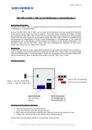
UPS WEB/SNMP MANAGER<br />
<strong>CS121</strong> Series
Copyright Statement for Intellectual Property and Confidential Information<br />
The information contained in this <strong>manual</strong> is non-conditional and may be changed without due<br />
notice. Although <strong>Generex</strong> has attempted to provide accurate information w ithin this document,<br />
<strong>Generex</strong> assumes no responsibility for the accuracy of this information.<br />
<strong>Generex</strong> shall not be liable for any indirect, special, consequential, or accidental damage<br />
including, w ithout limitations, lost profits or revenues, costs of replacement goods, loss or<br />
damage to data arising out of the use of this document<br />
<strong>Generex</strong> the manufacturer of the BACS products undertakes no obligations with this<br />
information. The products that are described in this brochure are given on the sole basis of<br />
information to its channel partners for them to have a better understanding of the <strong>Generex</strong><br />
products.<br />
<strong>Generex</strong> allows its channel partners to transfer information contained in this document to third<br />
persons, either staff w ithin their own Company or their own customers, either electronically or<br />
mechanically, or by photocopies or similar means. <strong>Generex</strong> states that the content must not be<br />
altered or adapted in any way without written permission from <strong>Generex</strong>.<br />
It is agreed that all rights, title and interest in the <strong>Generex</strong>’s trademarks or trade names<br />
(whether or not registered) or goodwill from time to time of <strong>Generex</strong> or in any intellectual<br />
property right including w ithout limitation any copyright, patents relating to the Products, shall<br />
remain the exclusive property of <strong>Generex</strong>.<br />
<strong>Generex</strong> w ill undertake to deal promptly w ith any complaints about the content of this<br />
document. Comments or complaints about the document should be addressed to <strong>Generex</strong><br />
Systems <strong>GmbH</strong>.<br />
Copyright of the European Union is effective (Copyright EU).<br />
Copyright (c) 1995-2012 GENEREX <strong>GmbH</strong>, Hamburg, Germany. All rights reserved.
2<br />
English Manual<br />
Dieses Handbuch ist auch in Deutsch verfügbar!<br />
Eine aktuelle Kopie erhalten Sie unter dow nload bei www.generex.de.<br />
This <strong>manual</strong> is also available in German!<br />
To obtain an actual copy please see the download-page of www.generex.de
Contents<br />
English Manual 2<br />
1. The <strong>CS121</strong> family - Introduction 6<br />
1.1 About your <strong>CS121</strong> 6<br />
1.1.1 General information 6<br />
1.1.2 Functionalities of your <strong>CS121</strong> 6<br />
1.2 About the communication w ith the <strong>CS121</strong>-Adapter 8<br />
1.3 The <strong>CS121</strong> Adapter Package 8<br />
1.4 Comparison 10<br />
1.5 <strong>CS121</strong> overview 11<br />
1.6 A typical installation - <strong>CS121</strong> in a network environment 13<br />
1.7 Connect your <strong>CS121</strong> ... 13<br />
1.7.1 ... via serial port 13<br />
1.7.2 ... via LAN 14<br />
1.8 Verifying the <strong>CS121</strong> connectivity 14<br />
2. Quickstart 15<br />
2.1 Setting up basic network configuration 15<br />
2.1.1 DHCP – Obtain an IP address automatically 16<br />
2.1.2 Establishment of a static <strong>CS121</strong> IP address <strong>manual</strong>ly (default delivery state)<br />
16<br />
2.1.3 Using HTTP/Webbrowser 16<br />
2.1.4 Using Telnet / MS-HyperTerminal 18<br />
2.1.4.1 Building up a connection 18<br />
2.1.4.2 Main menu & IP-Settings 19<br />
2.1.4.3 UPS Settings 20<br />
2.1.4.4 Save configuration 21<br />
2.2 Adapter-restart and boot procedure 21<br />
2.3 Introduction in the event configuration 21<br />
2.3.1 About same basic events 22<br />
2.3.2 Quickguide to install an RCCMD-job 22<br />
3. Configuration of the <strong>CS121</strong> 24<br />
3.1 <strong>CS121</strong> Status-Monitors 24<br />
3.2 Configuration 25<br />
3.2.1 UPS Model & System 25<br />
3.2.2 Netw ork & Security 27<br />
3.2.3 The <strong>CS121</strong> w ith DHCP utilization 28<br />
3.2.4 The <strong>CS121</strong> w ith ICMP Check 29<br />
3.2.5 Function hide of HTTP links 29<br />
3.2.6 Configuration Static ARP Entries 30<br />
3.2.7 Scheduled Actions 30<br />
3.2.8 Email 32<br />
3.2.9 Email Trap 33<br />
3.2.10 Email Trap Configuration 34<br />
3.2.11 Timeserver 35<br />
3.2.12 Language 38<br />
3.2.13 Events / Alarms 40<br />
3.2.13.1 Treshold events 41<br />
3.2.13.2 Logfile entries 42<br />
3.2.13.3 Email-Job 42<br />
3.2.13.4 Email-To-SMS 43<br />
3.2.13.5 RCCMD Jobs 44<br />
3.2.13.5.1 RCCMD Shutdow n 46<br />
3.2.13.5.2 Automatic Reset of the Redundancy Alarm 50<br />
3.2.13.5.3 RCCMD Execute/command 51<br />
3.2.13.5.4 Example of use 1: <strong>CS121</strong>-adapter as RCCMD-listener 51<br />
3
3.2.13.5.5 Example of use 2: <strong>CS121</strong>-adapter switches an output 52<br />
3.2.13.5.6 RCCMD Trap 54<br />
3.2.13.6 UPS shutdow n 54<br />
3.2.13.7 AUX-Port 54<br />
3.2.13.8 Wake on LAN (WOL) 55<br />
3.2.14 Scheduled Actions 55<br />
3.2.15 SNMP 56<br />
3.2.16 COM2 & AUX 57<br />
3.2.16.1 COM2 57<br />
3.2.16.2 AUX and SITESWITCH4 Settings 60<br />
3.2.17 SENSORMANAGER 60<br />
3.2.18 RAS Configuration 61<br />
3.2.19 Save Configuration / Reboot 62<br />
3.3 Reading the Logfiles 62<br />
3.4 <strong>CS121</strong> for Transfer Switches 65<br />
4. Adapter Software-Updates (Firmware) 66<br />
4.1 Firmw areupdate via Setup-tool 66<br />
4.2 Firmw areupdate via FTP 66<br />
4.3 Firmw are flash renewal and recovery 67<br />
4.4 How to get the “upsman.cfg” from a <strong>CS121</strong> to your computer via FTP 68<br />
4.5 Changing the Adapter’s MAC-Address 72<br />
5. Additional Software 74<br />
5.1 RCCMD 74<br />
5.1.1 Installation 74<br />
5.1.2 RCCMD w ith SSL for Windows 76<br />
5.1.3 RCCMD w ith own SSL certificates 78<br />
5.1.4 RCCMD client as relay station 79<br />
5.1.5 License regulations 79<br />
5.2 gChart 79<br />
5.3 UPS monitor (UPSMON) 81<br />
6. <strong>CS121</strong>-Enhancements, Field of applications 83<br />
6.1 SiteSw itch4 (SS4) and SiteSwitch4AUX (SS4AUX) 83<br />
6.1.1 SS4 Feature overview 84<br />
6.1.2 SS4 Contents 84<br />
6.1.3 SS4 Installation 84<br />
6.1.4 SS4 - Technical data 85<br />
6.2 Sensor SM_T_COM 85<br />
6.2.1 SM_T_COM configuration 86<br />
6.3 SENSORMANAGER & SENSORMANAGER II 87<br />
6.3.1 General information 87<br />
6.3.2 Installation and Netw ork integration 88<br />
6.3.3 Special features of theSENSORMANANAGER II 91<br />
6.3.4 Configuration 92<br />
6.3.5 Alarm Matrix of the SENSORMANAGER II 93<br />
6.4 RASMANAGER 94<br />
6.5 GSM Modem – Notification via SMS 95<br />
6.6 LED-Matrix Display 97<br />
6.7 MODBUS / PROFIBUS 98<br />
6.8 UNMS (UPS-Netw ork Management System) 99<br />
7. Troubleshooting – FAQ 101<br />
Appendix 103<br />
A. <strong>CS121</strong> - Technical data 103<br />
B. CE- and UL-Certification 103<br />
C. Cable and Circuit board configuration, Pin/AUX-Ports, SensorMan 103<br />
4
D. MODBUS Interface 107<br />
D.1. General information 107<br />
D.2. Available Modbus Function Codes 108<br />
D.3. Exception Codes 108<br />
D.4. MODBUS Modes in the <strong>CS121</strong> M (ASCII and RTU) 109<br />
D.5. UPS Parameter 110<br />
D.6. UPSMAN Status Bytes - Standard Device Status Bits 123<br />
D.7. Bus termination 124<br />
D.8. Configuration 124<br />
D.9. TCP/IP - UDP Ports 124<br />
D.10. MODBUS Cables 125<br />
E. Available Variables of the <strong>CS121</strong> 125<br />
F. Pin layout of Input-sockets of the SENSORMANAGER unit 127<br />
G. Events/Alarms of the <strong>CS121</strong> – Description of the alarms 127<br />
H. Description of the alarms for single-phase UPS 131<br />
I. Configuration of Microsoft SCOM 2007 as <strong>CS121</strong> Trap Receiver (Monitor)132<br />
J. RARITAN Dominion PDU Configuration 141<br />
Table of figures 145<br />
5
1. The <strong>CS121</strong> family - Introduction<br />
1.1 About your <strong>CS121</strong><br />
1.1.1 General information<br />
The <strong>CS121</strong>-series are a group of products designed especially for critical resource<br />
management w ithin technical facilities. The <strong>CS121</strong> can act as a UPS (uninterruptible power<br />
supply) manager for all other computers in the network. All of these products share many of<br />
the same basic <strong>CS121</strong> features, and some have special components and functions. The<br />
<strong>CS121</strong> products are most commonly used for the management of UPS systems, so in this<br />
<strong>manual</strong> w e specially reflect to the usage of such devices with your <strong>CS121</strong>. All of the basic<br />
features and most of the product specific features and operation are explained in this <strong>manual</strong>.<br />
This <strong>manual</strong> is the basis also for other <strong>CS121</strong> based products like <strong>CS121</strong>, <strong>CS121</strong>BUDGET,<br />
SENSORMANAGER, SM_T_COM, SITEMANAGER, SITEMONITOR, SITESWITCH4 und<br />
RASMANAGER.<br />
Note: When using the <strong>CS121</strong> to act as a UPS (uninterruptible pow er supply)<br />
manager for other computers in a network it is necessary for those<br />
computers that are being managed by the <strong>CS121</strong> to have its ow n<br />
RCCMD installation. RCCMD is the only possibility for enabling the<br />
communication between the <strong>CS121</strong> acting as a UPS-Manager and other<br />
client computers in a network. While it is possible to add the different<br />
computers as clients in the <strong>CS121</strong> settings it is only possible for those<br />
computers to act as an RCCMD client w hen they are running RCCMD.<br />
Each computer running RCCMD must have its ow n RCCMD license.<br />
This is the only possibility for the <strong>CS121</strong> to fulfil its function as a network<br />
UPS (uninterruptible pow er supply) manager. Setting up the RCCMD<br />
commands is described in depth in the sections 2.3.2 Quickguide to<br />
install an RCCMD-job and 5 Additional Software.<br />
There are several <strong>CS121</strong> SNMP-adapters available for different UPS and although they are<br />
mainly made for UPS, the adapters can easily be modified by simply plugging in other products<br />
like the SITESWITCH SS4-AUX, SENSORMANAGER, and Modems in order to add new<br />
features.<br />
There are two basic types of <strong>CS121</strong>-adapters: external and slot cards. The basic versions for<br />
UPS come w ithout MODBUS-protocol, COM2 for environmental sensors and manageability<br />
and AUX for dry-contacts alarms. For more differences please see section 1.4 Comparison.<br />
There are other external products based on the <strong>CS121</strong> such as the RASMANAGER, w hich is a<br />
<strong>CS121</strong> w ith a built-in modem. Other external devices include the SiteSw itch 4 (for the direct<br />
control over power sockets), the SITEMONITOR 64 (for monitoring up to 64 digital alarms) ,<br />
and the SITEMANAGER 2 (a device w ith multiple functions) which are used for handling<br />
facility management purposes that go beyond the UPS systems.<br />
Generally, the SNMP adapter runs an embedded Simple Netw ork Management Protocol<br />
(SNMP) software agent. This agent responds to the SNMP operations “gets” and “sets” and<br />
also forwards “trap-messages” to designated recipients when critical conditions occur to the<br />
UPS - such as low battery status. Additionally, the adapter can send RCCMD signals to client<br />
computers running the Remote Console Command (RCCMD) initiating automatic shutdow ns<br />
or other actions in case of an extended powerfail. (The RCCMD client is an extra system<br />
module requiring its ow n license.)<br />
1.1.2 Functionalities of your <strong>CS121</strong><br />
SNMP Adapter <strong>CS121</strong>/<strong>CS121</strong> Slot: The SNMP adapter is a compact unit requiring minimal<br />
workspace (ca. 28x69x126 mm for the external adapter <strong>CS121</strong>L). The slot card versions of the<br />
adapter (CS111 and <strong>CS121</strong>SC) get inserted into the extension slots of UPS models supporting<br />
its card type.<br />
Serial Port: Tw o DIP-sw itches change the adapter's serial port (COM2) to a configuration<br />
port for installation or to a communication port for environmental sensors, modem or other<br />
6
functions. The MODBUS-version uses the COM2 as RS485 and is not available for<br />
configuration. The MODBUS version can be configured only via Webbrowser, Telnet and<br />
Default IP address.<br />
SNMP-Traps for remote monitoring and pre-alarming: The main function of the SNMPadapter<br />
lays in the transmission of alarm conditions of the UPS to the monitoring station<br />
(SNMP traps and RCCMD traps/commands). It also makes UPS data access able for <strong>user</strong>s in<br />
the network upon request. With this function it is possible to retrieve and monitor eg. battery<br />
capacity of an UPS from an SNMP management station. The event settings configuration<br />
menu also allows for SNMP trap testing.<br />
Remote Control: With this function it is possible to switch the UPS to Bypass (depending on<br />
the model) or start battery tests. This remote command is executed either via the Network<br />
Management Station or the UPS Management Software or any Webbrowser.<br />
Telnet: Every Adapter maybe reconfigured via the network, using Telnet or http after the<br />
initial configuration of an IP Address for the adapter. Current UPS data can also be shown<br />
using Telnet. Generally we recommend to use the Webinterface since Telnet (and<br />
terminalconfiguration) does only allow to setup a basic configuration of the <strong>CS121</strong>.<br />
Works with all major NMS: The SNMP adapter w orks with most, w idely used Netw ork<br />
Management Systems e.g. HP Open View HP UNIX and Microsoft Windows NT, Novell NMS,<br />
Spectrum, Sun NetManager, IBM Net View /600 and others. All SNMP systems which either<br />
allow the compilation of the MIB or already incorporate MIB RFC 1628 for UPS Systems, can<br />
be operated with the Cs121.<br />
Multiserver shut down via RCCMD/RCCMD2 compatibility: The SNMP adapter <strong>CS121</strong> is<br />
able to initiate a netw ork shutdown w ith any RCCMD modules from the UPS- Management<br />
Software CD. A TCP/IP based RCCMD signal is sent to all RCCMD clients in the netw ork. This<br />
enables the remote shutdown of practically an unlimited number of client computers,<br />
independent of which operating systems the clients are running. RCCMD is an optional part of<br />
the UPS-Management Softw are. Your UPS dealer is able to provide you w ith Licensekeys for<br />
the RCCMD. The UPSMAN service of the UPS-Management Software suite is an optional<br />
module and not needed for that basic <strong>CS121</strong> operations. We recommend to use the UPSMAN<br />
service only if the UPS is connected via serial or USB cable, if a <strong>CS121</strong> is connected only the<br />
UPSMON (optional OEm designed Window s interface) and the Webbrowser are needed.<br />
RS-232 UPS Protocol Router – Pipe- through: The <strong>CS121</strong> (not BUDGET versions) is able<br />
to transfer the UPS RS-232 protocol on COM1 directly to COM2. This allow s the use of<br />
additional monitoring software on COM2 w hile making extra hardware (RS-232 multiplexer) to<br />
multiply the UPS comport unnecessary.<br />
Logfile: <strong>CS121</strong> has an internal logfile synchronized w ith either a set timeserver in your<br />
network or from timeservers in the internet. This logfile can be accessed through the<br />
Webbrowser, UPSMON, JAVAMON or via FTP. Due to the maximum file size of 250 lines<br />
(depends on Hardware, newer HW131 have 2-3 more space), old entries are deleted<br />
automatically.<br />
Network settings: The <strong>CS121</strong> Models are adjustable to the network environment. An autosensing<br />
function 10 or 100Mbit can be activated.<br />
Note: In large fast networks as is normally the case by CISCO or HP-Procurve<br />
with auto-sensing switches problems can occur during the reboot of the<br />
<strong>CS121</strong>. If this is the case and switches are being used then the autosensing<br />
function might very well be the problem. Because the <strong>CS121</strong> is<br />
per default set to auto-sensing (ON), this can lead to the netw ork<br />
devices not being able to harmonise communication rates with one<br />
another. This auto-sensing process can take a long time and is<br />
sometimes never attainable. This taxes the CPU capacities of the<br />
switches and can greatly slow down the network or even lead ultimately<br />
to its failure. In this case a default network speed should be determined<br />
7
and set after which, the <strong>CS121</strong> can be changed from AUTO to the given<br />
speed, "100half" for example.<br />
Email client: The <strong>CS121</strong> adapters incorporate a built-in SMTP email-client, w hich is able to<br />
send emails automatically in the event of an alarm.<br />
Web server: The <strong>CS121</strong> Models contain a w eb-server, which displays all functions and<br />
settings of the adapter. Non-Windows <strong>user</strong>s may use the JAVAMON as graphically display for<br />
UPS data (The JAVAMON module is not implemented in all versions.). Generally the <strong>CS121</strong><br />
Webserver is designed for the use with MICROSOFT INTERNET EXPLORER 6 w ith Active X<br />
and is recommended as configuration and management interface.<br />
1.2 About the communication with the <strong>CS121</strong>-Adapter<br />
MODBUS<br />
Modbus is the de facto standard protocol in industry which is used in the building surveillance<br />
and facility management. All <strong>CS121</strong> types include an MODBUS over IP interface and<br />
MODBUS over RS232. The <strong>CS121</strong> MODBUS types do not have an RS232 interface at COM2,<br />
here they use an RS485 interface. The <strong>CS121</strong> BUDGET series does not support MODBUS.<br />
Please see the appendix where also output and protocol interface are shown.<br />
SNMP<br />
The SNMP (Simple Netw ork Management Protocol) is the Internet-standard protocol for<br />
managing devices on IP netw orks and is defined and standardized in Requests for Comments<br />
(RFCs)-specifications. UPS systems are using in generally as Management Information Base<br />
(MIB) the RFC1628-specification which defines UPS-specific devices.<br />
The <strong>CS121</strong> also comes with the standard MIB RFC1628. Because of this MIB is already part<br />
of most SNMP software products, it is not required to compile the MIB (Please search the<br />
MIB2 directory tree for a “UPS-MIB”). If you w ant to include your <strong>CS121</strong>-adapter to an SNMP-<br />
Management station, w hich does not have the standard MIB RFC1628, you can dow nload the<br />
specific MIB from our w ebsite. (http://www.generex.de/e/download/cs12x/download_p.html)<br />
Copy the MIB file to the appropriate MIB-directory of your SNMP-station and compile this file.<br />
In most cases your SNMP already has implemented this MIB and a compilation is only<br />
necessary if you want to read extra information than just UPS (e.g. for SENSORMANAGER,<br />
etc.)<br />
For additional information about MIB and NMS see also the section “UNMS” later on in this<br />
<strong>manual</strong>.<br />
For the <strong>CS121</strong>-SNMP MIB Implementation, please refer to the GENEREX dow nload-page<br />
http://www.generex.de/e/download/cs12x/download_p.html<br />
This MIB is specially designed for the <strong>CS121</strong> and includes SNMP values for all <strong>CS121</strong> optional<br />
products (Temperature, humidity, alarm contacts, etc.) Basicly this RFC1628<strong>CS121</strong>.MIB is the<br />
original UPS MIB, extended by extra values supported from your <strong>CS121</strong>.<br />
TCP<br />
Most common w ay to communicate w ith the <strong>CS121</strong>-adapter is over TCP. <strong>CS121</strong> includes<br />
UPSTCP, w ith gives you a complete interface to integrate the adapter into your network.<br />
1.3 The <strong>CS121</strong> Adapter Package<br />
The standard <strong>CS121</strong>-adapter package contains an SNMP-adapter unit w ith supporting<br />
hardware and software. (Note, that the Budget-models do not have all features.)<br />
Optional is a mounting kit for wall and DIN Rail mounting.<br />
8<br />
Product Included in delivery<br />
<strong>CS121</strong>L<br />
(Extern)<br />
Pow er supply external. (For USA/CA UL: Supplied by NEC Class 2<br />
Pow er supply only) User <strong>manual</strong> English. Configuration cable for serial<br />
port configuration via Terminalsoftware - and for connection of optional<br />
devices for your <strong>CS121</strong>.
<strong>CS121</strong>SC<br />
(Slot Chinese)<br />
<strong>CS121</strong>F<br />
(Slot FUJI)<br />
<strong>CS121</strong>R<br />
(Slot<br />
RIELLO/AROS)<br />
<strong>CS121</strong>MOD<br />
(Extern)<br />
<strong>CS121</strong>BL<br />
(Budget Extern)<br />
<strong>CS121</strong>BSC<br />
(Budget Slot<br />
Chinese)<br />
User <strong>manual</strong> English. Configuration cable for serial port configuration<br />
via Terminal software - and for connection of optional devices for your<br />
<strong>CS121</strong>.<br />
User <strong>manual</strong> English. Configurationcable for serial port configuration<br />
via Terminalsoftware - and for connection of optional devices for your<br />
<strong>CS121</strong>.<br />
User <strong>manual</strong> English. Configurationcable for serial port configuration<br />
via Terminalsoftware - and for connection of optional devices for your<br />
<strong>CS121</strong>.<br />
Pow er supply external. (For USA/CA UL: Supplied by NEC Class 2<br />
Pow er supply only) User <strong>manual</strong> English. Configuration cable for serial<br />
port configuration via Terminal software - and for connection of optional<br />
devices for your <strong>CS121</strong>. Mini-8 connector for your MODBUS RS-485<br />
connection via COM2.<br />
Pow er supply external. (For USA/CA UL: Supplied by NEC Class 2<br />
Pow er supply only) User <strong>manual</strong> English. (Configuration only via<br />
networkcable)<br />
User <strong>manual</strong> English. (Configuration only via network cable )<br />
9
1.4 Comparison<br />
<strong>CS121</strong> FEATURES and Supported <strong>CS121</strong> COMMON FEATURES FOR ALL<br />
MODELS OPTIONS UPS models MODELS *<br />
<strong>CS121</strong>L Second mini din 9<br />
external COM port for<br />
RS232. AUX port<br />
for digital input/<br />
output. MODBUS<br />
RS485 option.<br />
Remote RAS<br />
management<br />
options.<br />
<strong>CS121</strong>SC slot Like <strong>CS121</strong> L<br />
external.<br />
All 1400 UPS All <strong>CS121</strong> devices are capable of managing<br />
models from the UPS models for which they are compatible<br />
over 60 via the UPS’s native serial protocol. Each<br />
different UPS <strong>CS121</strong> integrates seamlessly into all<br />
manu- contemporary SNMP facility management<br />
facturers. systems.<br />
All <strong>CS121</strong> models have their own web server<br />
with configurable event management for<br />
All Chinese/<br />
automating responses to power and UPS<br />
Taiwanese<br />
status conditions. This includes Emails<br />
standard slot<br />
transmission, RCCMD net w ork messages and<br />
UPS models.<br />
shutdowns, logfile entries, grafical logfile for<br />
statistics, RCCMD Traps, UPS shutdown<br />
functions and wake-up calls for computers<br />
<strong>CS121</strong>F<br />
FUJI slot<br />
Second mini din 9<br />
COM port for<br />
FUJI UPS which have been shutdowned before (wake-onlan).<br />
RS232. AUX port<br />
All actions and events may be configured<br />
for digital input/<br />
individually.<br />
<strong>CS121</strong>R<br />
Riello slot<br />
output. Remote<br />
RAS management<br />
options.<br />
Like <strong>CS121</strong> F. Riello and<br />
Aros UPS<br />
All <strong>CS121</strong> have a built-in scheduler for regular<br />
tasks like battery tests, battery calibration and<br />
UPS shutdow n/restore.<br />
All <strong>CS121</strong> have a wide range of network<br />
management features for alarming <strong>user</strong>s and<br />
managing other SNMP devices and general<br />
overall Computer and Pow er resource<br />
<strong>CS121</strong>BL Economic <strong>CS121</strong> All 1400 UPS<br />
management via RCCMD.<br />
All <strong>CS121</strong>s include MODBUS-over-IP and an<br />
optional MODEM interface.<br />
BUDGET<br />
external<br />
with LAN UPS models from All <strong>CS121</strong>s (except BUDGET models) offer a<br />
management only. over 50 COM2 for connecting environmental sensors or<br />
(No AUX port for different for connecting other products and software to<br />
dry contacts, no manufacturer. manage the UPS.<br />
COM2 interface for<br />
modem or<br />
All <strong>CS121</strong> have 2 years warranty and a free<br />
environmental<br />
update period of 3 years. All <strong>CS121</strong> are made<br />
sensors.<br />
in Germany.<br />
<strong>CS121</strong>BSC Like <strong>CS121</strong> All Chinese/<br />
BUDGET slot BUDGET External Taiwanese<br />
standard slot<br />
UPS models.<br />
10
1.5 <strong>CS121</strong> overview<br />
For <strong>CS121</strong>L, C and Slot card types<br />
No. Description<br />
Figure 1: Connectors of the <strong>CS121</strong><br />
<strong>CS121</strong> family:<br />
<strong>CS121</strong>L = external device with external power supply 9V (US: 12V)<br />
<strong>CS121</strong>SC = slot device for Chinese UPS w ith slot (also as BUDGET, <strong>CS121</strong>BSC).<br />
<strong>CS121</strong>F = slot device for FUJI UPS Japan<br />
<strong>CS121</strong>R = slot device for RIELLO/AROS UPS Italy<br />
<strong>CS121</strong>MOD = external device with MODBUS RS485 port<br />
<strong>CS121</strong>CS MOD = slot device w ith MODBUS RS485 port<br />
<strong>CS121</strong>BL = external device BUDGET-Model (does not have COM2- and AUX-port)<br />
<strong>CS121</strong>BSC = slot device BUDGET-Model (does not have COM2- and AUX-port)<br />
The <strong>CS121</strong> FirmWare Version 4.30.x provides devices, which are running with 88MHz only.<br />
Those kind of devices have to be selected, if the power supply is not sufficient. With the<br />
selection of a 88MHz device, the power consumption of the <strong>CS121</strong> w ill be halved. Therefore<br />
an operation into weak supplied UPS slots is possible.<br />
(1) LED-Status of Network connectivity: The LEDs w hich are integrated into the RJ45<br />
connector (see No. 1 in the figure above) w ill signal w ith green a connection to the network<br />
and w ith yellow network communication.<br />
Green LED Red LED Adapter<br />
OFF ON Adapter is looking for UPS/initializing. The start phase can<br />
take up to 2 minutes<br />
Flashing OFF Data flow/normal mode of the UPS<br />
(1) Netw ork connection RJ45 10/100 Base T<br />
Connector (w ith Status LED, green=link,<br />
yellow =activity)<br />
(2) Serial com-port (COM2) for configuration<br />
or connection of optional devices. (not<br />
BUDGET versions)<br />
(3) Error/Link LED UPS Status (Red=boot or<br />
error, Green (flashing) = normal<br />
(4) AUX Input/Output for dry contact alarms<br />
and relays<br />
(5) DIP-Sw itches for configuration mode<br />
(6) Serial port (COM1) for UPS connection<br />
(at BUDGET for terminal configuration)<br />
(7) (12V) DC Connection (Outside US : 9V-<br />
30V)<br />
ON ON Communication to UPS interrupted<br />
(2) LED-Status of the <strong>CS121</strong> HW131: The follow ing table is valid for the <strong>CS121</strong> HW131<br />
only.<br />
Operating Condition <strong>CS121</strong> HW 131 LED-Signaling<br />
Start procedure 1, unpacking of the OS red flashing<br />
Start procedure 2, reboot of the OS red long on<br />
11
If the red and green LED shine at your <strong>CS121</strong><br />
HW131 during the reboot, huge broadcast traffic into<br />
your network is present „recieve buffer overflow“.<br />
The green LED is signalizing at the reboot, that the<br />
„traffic buffer“ is full. Advice: You should filter<br />
broadcasts via your switch, because it comes to<br />
performance losing of the <strong>CS121</strong> HW131<br />
unnecessary.<br />
12<br />
red AND green during reboot<br />
Normal condition green flashing<br />
UPS communication lost red constantly<br />
(3) DIP-Sw itches: The DIP-Sw itches differentiate between two functions: Configuration- and<br />
normal mode.<br />
Figure 2: DIP-Switches: <strong>CS121</strong>L (left) in configuration mode (IP 10.10.10.10) and <strong>CS121</strong>SC<br />
(right) in normal mode<br />
Sw itch 1 Sw itch 2 Description<br />
ON OFF Normal operation, device runs on the configured IP-address<br />
OFF OFF Configuration mode w ith default IP Address<br />
10.10.10.10 and active COM 2 configuration for Terminal<br />
SW<br />
Note: In the configuration-mode the full functionality of the <strong>CS121</strong> is not<br />
provided! Please change to a valid network address and put DIP-sw itch<br />
1 to position ON as soon as you made your basic network setting! After<br />
this, please continue configuring your <strong>CS121</strong> in your network. Please<br />
follow up the procedure in chapter 2 Quickstart in this <strong>manual</strong>.<br />
Additional information for <strong>CS121</strong>BL/<strong>CS121</strong>BSC: The BUDGET-versions do not have an<br />
external connection for COM2. This configuration interface has been routed to COM1 (UPS<br />
port).<br />
(4) Power supply: A power supply adapter (wall socket unit) (DC, 12V) provides power for<br />
the Adapter (external Model <strong>CS121</strong>L, <strong>CS121</strong>MOD, <strong>CS121</strong>BL only).<br />
Note: If you are using a different power supply unit from the one in the adapter<br />
package, please consider that the polarity is set correctly. The adapter<br />
might be damaged if the wrong polarity is used. The power supply<br />
voltage should be at least 9V, 12 V is recommended.<br />
For the <strong>CS121</strong>SC models C and the slot card, there are no power supply<br />
units. These units w ill receive power directly from the UPS device. The<br />
SNMP adapter C and slot card both incorporate a variable 9-36V input.<br />
UPS Interface cable (extern devices only): Please use the manufacturer’s serial port cable that<br />
came w ith your UPS to connect the UPS w ith the SNMP-adapter. Please contact your UPS<br />
manufacturer, if you have questions. Only use the original RS-232 UPS cable for<br />
communication, which w as provided w ith the UPS. If your UPS has a contact closure port,<br />
please use the manufacturer’s special cable. Please consult your UPS dealer on information<br />
regarding special cables.
1.6 A typical installation - <strong>CS121</strong> in a network environment<br />
A typical installation on the SNMP-adapter monitoring a UPS in an Ethernet netw ork follows in<br />
the illustration below. The SNMP-adapter communicates w ith the UPS to inform you about<br />
your systems power condition.<br />
Figure 3: <strong>CS121</strong> in a network environment<br />
1.7 Connect your <strong>CS121</strong> ...<br />
In generally you can choose between 3 ways to configure the <strong>CS121</strong>-adapter:<br />
By using the serial port you can make the configuration via a Terminalprogram such as e.g.<br />
Microsoft-HyperTerminal. This configuration-mode allows you to make the fundamental<br />
settings for network connectivity and for defining the event and action-settings.<br />
By using a LAN-connection you can make the configuration via Telnet or Webbrowser:<br />
The configuration via Telnet supports the same interface as the configuration via<br />
Terminalprogram.<br />
The configuration via Webbrowser allows you to make all kind of settings and configurations.<br />
If you have any possibility, we recommend you to configure the <strong>CS121</strong>-adapter via this way.<br />
Note: External versions: At the <strong>CS121</strong>BL in configuration-mode a zero-modem<br />
cable (not included) may be connected to COM1. Please use a Terminal<br />
program to configure your <strong>CS121</strong> via this connection. Option: At UPS<br />
with a DIP-Sw itch to configure between the UPS built-in serial port and<br />
outside serial port (e.g. UPS from PHOENIX TEC) you may insert the<br />
<strong>CS121</strong>BSC into the slot and use the original UPS cable for configuration<br />
via Terminal. We recommend to use the webbrowser as configuration<br />
interface.<br />
1.7.1 ... via serial port<br />
The SNMP adapter incorporates two serial ports (not BL and BSC-versions), whereas COM1<br />
(see figure “Connectors of the <strong>CS121</strong>” above) provides the connection to the UPS and COM2<br />
is used to configure the SNMP-adapter.<br />
<strong>CS121</strong>BSC:<br />
At the <strong>CS121</strong>BSC in configuration mode you can use the original UPS serial cable of the UPS<br />
and the in-built RS232 UPS interface to connect your <strong>CS121</strong>BSC via a Terminalprogram.<br />
For the <strong>CS121</strong>BSC exists also the possibility to make the configuration via COM1. Therefore<br />
you have to set DIP-sw itch 1 in Position OFF and connect to COM1 port to the serial port of<br />
your workstation.<br />
13
<strong>CS121</strong> MINI/<strong>CS121</strong> R_II:<br />
It is required, that the DIP Sw itch 2 remains in position OFF, otherw ise the device will not start<br />
(valid for <strong>CS121</strong>Minislot/CS125/<strong>CS121</strong>R_II built 2008- 2010 from serial number 0123M-0001<br />
to 0123M-1135).<br />
Configuration cable (not <strong>CS121</strong>BL/BSC):<br />
Your package contains a configuration cable, which connects to the serial port (COM2) of the<br />
SNMP-adapter and the serial port of a PC w ith terminal software. It is sufficient to use a Dumb-<br />
Terminal or Terminal-Emulationprogram, such as e.g. Microsoft-HyperTerminal. During the<br />
configuration of the SNMP adapter please ensure that the DIP sw itches are in the correct<br />
position. Please also refer to the section 1.5 <strong>CS121</strong> overview in this <strong>manual</strong>.<br />
1.7.2 ... via LAN<br />
Connect the <strong>CS121</strong> w ith RJ45 cable (not included) to your LAN.<br />
1.8 Verifying the <strong>CS121</strong> connectivity<br />
After the <strong>CS121</strong>-adapter is connected to the UPS and to the Computer via serial port or via<br />
LAN, please verify the connectivity before you start to configure the <strong>CS121</strong>. The setup system<br />
can be checked before and after a configuration using the follow ing 3 steps:<br />
UPS-Status displays (LEDs)<br />
During the boot-procedure, the red LED is on, whereas the green LED is off. (Models with<br />
Hardw are Version131 do also indicate uncompressing the firmw are files with flashing red LED<br />
lightening) The boot process can take up to 3 minutes. If there is an error, the red LED does<br />
not go out. For more detailed information about the UPS-Status LEDs, please see section 1.5<br />
<strong>CS121</strong> overview.<br />
After five to ten seconds after the boot-process, the green LED flashes rapidly; this indicates<br />
that the SNMP-adapter is trying to start the communication. The adapter will indicate its<br />
communication accessibility w ith random green LED flashes.<br />
Network status LEDs<br />
The LEDs, integrated into the LAN-Connector (RJ45-), w ill signal a connection to the network<br />
with green and with yellow network connectivity.<br />
14<br />
Ping the SNMP-Adapter<br />
Perform a PING-command from the SNMP-station or from another computer in your network<br />
resp. NMS (Netw ork Management Station).<br />
If you do not get a response, check the SNMP-adapter network connection and IP-address of<br />
the SNMP adapter. The IP-address of the adapter is set to 10.10.10.10 if DIP-sw itch 1 is in<br />
position OFF (configuration-mode).<br />
Note: The different response rates during the ping process do not correspond<br />
to an error. The adapter does not answer every ping signal at the same<br />
speed, due to different sized UPS protocols. If UPS protocols are of<br />
extensive size a timeout can occur briefly. A permanent timeout how ever<br />
is an error.
2. Quickstart<br />
The Quickstart <strong>manual</strong> gives you a short instruction into the main features and how to make<br />
some basic settings and guides you in connecting the SNMP-adapter to the network and UPS.<br />
Note: Before you start to configure the <strong>CS121</strong> please ensure that your<br />
connections are valid as described in section 1.8 Verifying the <strong>CS121</strong><br />
connectivity (Red network-LED off; green network-LED flashing in<br />
intervals). Please take care that your UPS has been correctly installed<br />
before and is running!<br />
There are three methods available for configuring the SNMP-adapter: Telnet, terminal and<br />
HTTP. These methods differ in the type of <strong>user</strong> interface and in the type of connection to be<br />
used for the configuration. The telnet method shares similarities w ith both, the terminal and the<br />
HTTP-method. Like the HTTP-method, the telnet method uses a network connection via the<br />
IP-address to establish a communication, but it has the same type of <strong>user</strong> interface as used in<br />
the terminal-method. The terminal-method requires that the SNMP-adapter be connected via<br />
the serial cable to a host computer. The terminal and telnet methods provide the <strong>user</strong> with a<br />
text menu indicating per alpha-numeric keys the possibilities for the <strong>user</strong> to either enter<br />
configuration commands or navigate through the menu levels. The HTTP-method provides the<br />
<strong>user</strong> with forms in which the system settings are either typed directly into a form or chosen per<br />
drop down menu.<br />
Although, all of the configuration possibilities, Telnet, Terminal and HTTP are generally<br />
available, later in the parts of this <strong>manual</strong> only the explanation for usage of the HTTP-interface<br />
will be provided. We strongly recommend to use the HTTP interface for configuration and<br />
monitoring.<br />
After you have completed the hardware setup and connected the SNMP-adapter, any of these<br />
three methods can be used to configure the adapter for the network. For this purpose<br />
depending on the configuration method, a communication must be established between the<br />
adapter and <strong>user</strong> via a serial terminal session or via an established network route in a telnet or<br />
HTTP session. <strong>CS121</strong> allows a login only under the <strong>user</strong>name “admin”. Upon entering a<br />
telnet- or terminal-session with the adapter an authorization is required for which the default<br />
password is:<br />
“cs121–snmp”<br />
2.1 Setting up basic network configuration<br />
Note: We recommend the follow ing settings for the operation of the <strong>CS121</strong> via<br />
cross cable (Ethernet cable for the connection directly). Set the IP address of the PC w ith a<br />
cross cable to an IP address of the same network segment, e.g. 10.10.10.11 AND set the<br />
gateway to 0.0.0.0.<br />
A network cross cable is a PC-PC netw ork cable which does not require a switch or a hub<br />
between 2 network computers (2). Most modern computers networkcards have an<br />
autodetection, so any network cable may be used. Only if you do not have such a cable<br />
autodetection its unavoidable to use a Cross-cable or connect a switch or Hub between your<br />
PC and the BACS WEBMANAGER (1).<br />
15
Figure 4: Connection PC-Switch/Hub and <strong>CS121</strong> (2) Connection PC-Cross Cable/Network<br />
Cable and <strong>CS121</strong><br />
2.1.1 DHCP – Obtain an IP address automatically<br />
By default DHCP is off at all <strong>CS121</strong>. From <strong>CS121</strong> FirmWare Version 4.25.x you can switch on<br />
DHCP via DIP sw itch 2 <strong>manual</strong>ly. Therefore the <strong>CS121</strong> will get a DHCP IP address from the<br />
DHCP server during reboot. Prior of that, you should detect the MAC address of the <strong>CS121</strong> to<br />
be able to find the IP address on your DHCP server. We recommend to use static IP<br />
addresses, because the <strong>CS121</strong> is used for multi server shutdowns via RCCMD too and it<br />
might be, that the DHCP server got a breakdown. For that reason the delivery state of the<br />
<strong>CS121</strong> is alw ays with DHCP OFF!<br />
16<br />
Note: The function DHCP ON/OFF is valid for the follow ing models only: all<br />
<strong>CS121</strong> HW 131 and all BACS II Webmanager Budget (not valid for all<br />
<strong>CS121</strong> HW 121, SieteManager, SiteMonitor, MiniSlot and Piller I/O<br />
Board)!<br />
2.1.2 Establishment of a static <strong>CS121</strong> IP address <strong>manual</strong>ly (default delivery state)<br />
The minimum requirement to operate the SNMP-adapter is to set the IP address, subnet mask<br />
and the UPS model:<br />
The DIP-sw itches of the SNMP-adapter firstly need to be set for the configuration. DIPswitch<br />
1 is sw itched OFF in the top position as well as DIP sw itch 2 is sw itched OFF. Please<br />
note that the DIP sw itches of the SNMP-slot card adapter are situated on top of the circuit<br />
board and DIP sw itch 2 remains in the OFF position in configuration as well as in the normal<br />
mode.<br />
Note: For slot versions you have to insert and remove the device for any<br />
reboot-process. This w ill not have any effect on your UPS but w e<br />
recommend doing such operations only when the UPS is not supplying<br />
any load!<br />
As soon as the network-LED is flashing, add a TCP/IP route on your computer for IPaddress<br />
10.10.10.10. This is done via a call from your command line e.g. "route add<br />
10.10.10.10 “. See also route -? for more help of route syntax.<br />
Test if you can ping the device now: Enter command „ping 10.10.10.10“ and check if there is<br />
any response. Now you can connect w ith any Telnet or HTTP-software and continue w ith the<br />
configuration.<br />
2.1.3 Using HTTP/Webbrowser<br />
The entire configuration can be done via Webbrowser. Please use the default IP-address<br />
10.10.10.10 and the TELNET password (default: “cs121-snmp”). The <strong>user</strong>name is always<br />
“admin”.<br />
For the configuration using the webbrowser please observe the following:
We recommend the use of Microsoft Internet Explorer 6.x (or higher) or Mozilla 1.3x. Please<br />
note, that Java scripting has to be activated. Using Internet Explorer, the corresponding<br />
settings have to be made under “Internet options” - “security”.<br />
We also recommend never to use the history function of the browser, as this may lead to<br />
multiple transfer of commands (e.g. delete event jobs) to the adapter.<br />
Upon entering a HTTP-configuration session, the <strong>user</strong> is required to enter a <strong>user</strong>name,<br />
”admin”, in addition to the password ”cs121-snmp”.<br />
Figure 5: HTTP - Administrator login<br />
Note: If the HTTP-method does not seem to be available, check to see<br />
whether or not the red LED UPS Status (see section 1.7 Connect your<br />
<strong>CS121</strong> ...) is lit.<br />
Call Configuration, “UPS Model & System” and choose your UPS Model from the drop<br />
dow n list. Further configurations like Pow er, baud rate, cable type etc. were made<br />
automatically (ensure your Browser has enabled JavaScript) and do not need to be set. We<br />
strongly recommend to keep the default settings for this UPS unless you have instructions<br />
from the UPS maker.<br />
Figure 6: HTTP - UPS Model & System Settings<br />
Apply your settings with the button at the right side.<br />
Change to menu “Netw ork & Security” and specify IP-address, Gateway and Subnet mask<br />
to the <strong>CS121</strong>-adapter.<br />
17
Figure 7: HTTP - Network & Security Settings<br />
18<br />
Apply your settings with the button at the right side.<br />
Change to menu “Save Configuration” and click “Save Configuration”.<br />
2.1.4 Using Telnet / MS-HyperTerminal<br />
2.1.4.1 Building up a connection<br />
Use of Telnet, enter the command: „telnet “, whereas is in the<br />
configuration mode set to 10.10.10.10.<br />
Start a Terminalprogram (e.g. MS-HyperTerminal) and ensure that the serial communication<br />
cable for COM2 is connected. To build up the connection, mind the follow ing communication<br />
settings:<br />
Baud rate<br />
Adapter<br />
9600<br />
Data bits 8<br />
Parity None<br />
Stop Bits 1<br />
Flow Control<br />
Xon/Xoff<br />
None<br />
Handshaking None<br />
CR/LF OFF<br />
Local Echo OFF<br />
Terminal Type ANSI (VT100)<br />
Figure 8: Terminal communication settings<br />
Please confirm this w indow w ith OK w hen you have done all settings. The Terminal is now<br />
ready for communication w ith the SNMP-adapter and the main menu w ill start after the<br />
password has been entered. (Default password is “cs121–snmp”).<br />
Note: The number of password-characters is limited in Telnet. Please do never<br />
use a password longer than 15 characters if you intend to use the<br />
configuration via Telnet!
2.1.4.2 Main menu & IP-Settings<br />
Figure 9: Telnet - Main Menu<br />
To select any option in the main menu enter the number of the option at the Enter command<br />
=> prompt. The program displays the desired screen.<br />
Type 1 at the prompt and you enter the menu “IP Settings”. Within this menu you can<br />
enter basic network configurations, e.g. IP-address, Gateway-address etc.<br />
Figure 10: Telnet - IP Settings<br />
To change values, enter the number of the option, type and enter the name. Press<br />
. Your new value displays next to the field heading on the top of the screen. If you want<br />
to return to the main menu, press 0 (zero) and .<br />
For example: To assign the IP-address of the SNMP-adapter, the gateway and the subnet<br />
mask type at the prompt:<br />
1, , the IP address of the SNMP adapter, <br />
Enter Command => 1 192.10.200.0<br />
Enter Command => 2 192.10.200.254<br />
Enter Command => 3 255.255.255.0<br />
To assign the system contact name, type 5 and enter the name of the person to contact about<br />
the SNMP adapter.<br />
Enter Command => 5 Mr. Harry Hirsch<br />
To assign the UPS name SysName, type 5 and enter name of the UPS:<br />
19
Enter Command => 6 USV 1<br />
To assign the UPS location SysLocation, type 6 and enter the location name:<br />
Enter Command => 7 Building 12<br />
2.1.4.3 UPS Settings<br />
Choose option 4 from the main menu and you enter the menu “UPS Settings”. Within this<br />
menu the <strong>user</strong> needs to select the UPS model the <strong>CS121</strong>-adapter is connected to (usually at<br />
COM1).<br />
Figure 11: Telnet - UPS Settings<br />
The <strong>CS121</strong>-adapter distinguishes here generally between Cable- and Serial-models. With<br />
Cable, the adapter and the contact interface of the UPS are connected with a special cable.<br />
Using Serial, UPS models connect to the adapter via the serial UPS-cable. (Part of the UPS<br />
package). Serial is default, when the <strong>user</strong> selects a UPS model name from the drop-dow n list.<br />
When Cable is used, please search the list for the corresponding UPS model and cable type.<br />
The CS-121 supports serial models w ith its own RS-232 protocol as well as contact UPS<br />
models w ith the cable types O,C,1-10. Those contact cables are UPS or alarm system specific<br />
and should be provided by the corresponding manufacturer. Our Cable documentation shows<br />
examples of those cables if they are individually made cables.<br />
Please choose the corresponding Serial UPS model or Cable-model communication<br />
parameters. Parameters like baud rate etc. are preset for the corresponding UPS model.<br />
Note: By selecting the UPS model, the communication protocol is selected at<br />
the same time. If your UPS does not appear in the list, ask your UPS<br />
dealer if another model from the same series can be substituted.<br />
Select Option 1 to get a variety of possible UPS models. After chosen a model, the default<br />
values of the corresponding UPS model can be configured by typing the number of the option<br />
followed by the value.<br />
Note: Please do not change parameters except of UPS-model unless you want<br />
to choose specified configuration according your UPS-model!<br />
Please note option “D”: “System shutdown (minutes before battery end – downtime)“: This<br />
value determines how many minutes before a complete battery unload the event “System<br />
shutdown” from event menu is executed.<br />
The shutdown time interval needs to be set large enough, so that adequate time for a system<br />
shutdown is allocated before the UPS runs out of power. Please calculate this value<br />
generously e.g. if the battery time of the UPS is 10 minutes and the event procedure takes 2,5<br />
20
minutes, ensure you start (configure) the shutdown (or other event action) 3 minutes before the<br />
UPS is sw itched off, so that more than enough time is available to complete the corresponding<br />
event action.<br />
2.1.4.4 Save configuration<br />
Call “Save, Exit and Reboot”-command from the main menu. (The communication to the<br />
adapter will be lost).<br />
ATTENTION: Keep the Telnet, Terminal, Webbrowser w indow open until the device has been<br />
lost or you see a message that reboot is under progress. If you close the configuration w indow<br />
too early it may corrupt the upsman.cfg configuration file. (see also section 4 Adapter<br />
Software-Updates (Firmw are))<br />
Note: Various options and settings for UPS-configuration can be done under<br />
Telnet or HyperTerminal, e.g. setting access controls of the SNMPcommunities,<br />
set traps, set display settings, etc. However, the<br />
configuration via Webbrowser offers a much more convenient way to<br />
configure the <strong>CS121</strong>. If you have any possibility w e recommend you to<br />
use this way.<br />
2.2 Adapter-restart and boot procedure<br />
After you have finished the basic IP- and netw ork-settings you should set DIP-sw itch 1 in<br />
position ON and restart the adapter w ith your configurations.<br />
You can perform an adapter restart by unplugging the power supply of the <strong>CS121</strong> and w ait<br />
until the adapter has restarted w ith your configurations.<br />
Alternatively you can restart the Adapter w ith the “Reboot”-Option in the “Save Configuration”-<br />
menu of the Webbrowser. The follow ing message will displayed:<br />
Figure 12: HTTP – Adapter reboot dialog<br />
A successful restart of the adapter is indicated w ith the <strong>CS121</strong> UPS- and netw ork-LEDs as<br />
described in section 1.7 Connect your <strong>CS121</strong> ....<br />
Reconnect your Webbrowser w ith the adapter using the configured IP-address. (e.g.<br />
http://192.168.10.123)<br />
Your <strong>CS121</strong>-adapter is now ready for further configurations!<br />
Note: If the adapter’s HTTP-service is not available, check to see whether or<br />
not a red Status-LED is lit.<br />
Further, test if you reach the adapter w ith a ping-command. Enter<br />
command „ping “. If the adapter doesn’t answer to the ping,<br />
check also whether your network routes the IP-address.<br />
2.3 Introduction in the event configuration<br />
The configuration of the <strong>CS121</strong> is based on events, whereupon an event can be an UPStriggered<br />
event such as powerfail, battery low etc., and also events, which are released by the<br />
<strong>CS121</strong>-adapter, like events from the AUX-port or a connected SENSORMANAGER for<br />
example.<br />
The <strong>CS121</strong>-configuration allows you to assign one or more actions to each event. An action<br />
can be to send an Email-notification to specific <strong>user</strong>s as well as to perform a shutdown-signal<br />
21
to several client stations. In addition, it is possible to specify when and how often an action is<br />
to be released.<br />
2.3.1 About same basic events<br />
Please call the menu “Events / Alarms” in the Web-browser to open the main configurationsite,<br />
whereon all configurable events are listed. In the following, we introduce same basic and<br />
important events which should be in general handled from every <strong>CS121</strong>-Adapter. For a<br />
complete description in-deep please see section 3 Configuration of the <strong>CS121</strong>.<br />
22<br />
Powerfail<br />
The event “Pow erfail” will be released when the UPS has lost the power supply. This event is<br />
usually used to proceed operations like backup-strategies, batch-files to be executed on client<br />
stations etc. pp. You can configure such jobs w ith the “Remaining time”-parameter to ensure<br />
the actions w ill be executed completely.<br />
System shutdown<br />
The event “system shutdown” will be released, if the configurated “System Shutdow n Time” (in<br />
the menu “UPS model and system”) is reached. This means, there are yet the configurated<br />
minutes left until the battery’s capacity is expected to be finished (as calculated by the<br />
adapter).<br />
This event should only be used to proceed all operations concerning your forced shutdown<br />
szenarios. Further operations are usually configurated on the event “Pow erfail”.<br />
Battery low<br />
Note: This EV ENT is the final task a <strong>CS121</strong> can initiate before the UPS<br />
switches off! DO NOT use this EVENT for triggering shutdowns via<br />
RCCMD etc. because the remaining time in this status is not secure. We<br />
strongly recommend to use the event “Pow erfail” and configure the<br />
RCCMD shutdown calls w ith a UPS “remaining time”, this is the best<br />
way to send RCCMD shutdowns to several IP-addresses in a certain<br />
logic or sequence!<br />
The event “Battery low” will be released from the UPS w hen the battery charge has reached a<br />
critical state.<br />
UPSMAN started<br />
The event “UPSMAN started” is periodically released in normal operating mode. You can use<br />
this event to configure jobs, which should be executed as long as the adapter is working in<br />
normal mode.<br />
Note: Same UPS models allows you to configure the thresholds for releasing<br />
UPS specific events individual. <strong>CS121</strong> also supports these features if the<br />
UPS includes this possibility. See also section Error! Reference source<br />
not found. Error! Reference source not found. in this <strong>manual</strong>.<br />
2.3.2 Quickguide to install an RCCMD-job<br />
Condition for setting-up an RCCMD job in the <strong>CS121</strong> configuration (like Shutdown for<br />
example) is the installation of RCCMD at the client workstation.<br />
Note: Each RCCMD- Installation requires a licence key! Usually, the <strong>CS121</strong><br />
Adapter Package includes already one licence key. This license key can<br />
only be used once per installation. If more computers need to be added<br />
to the shutdown process, additional licenses are required.<br />
Please follow the description in section 5.1 RCCMD to install RCCMD at the client-workstation.<br />
After you finished the client-side installation of RCCMD you can configure an RCCMD-job at<br />
the <strong>CS121</strong>-adapter:
For example to configure a job, which initiates a shutdown-signal to a client-workstation,<br />
please enter the event “System shutdown” in the menu “Events / Alarms”. The following “Event<br />
Editor” then lets you add a new job.<br />
Figure 13: HTTP – Job Editor – Introduction<br />
See the figure above, how to configure the RCCMD shutdown for a Client-Workstation. Note,<br />
that you enter the correct IP-Address of the Client.<br />
Now the RCCMD shutdown procedure is already completed. Press the “Test”-Option in the<br />
Event Editor to verify your settings.<br />
23
3. Configuration of the <strong>CS121</strong><br />
24<br />
Note: After you have finished the basic network configuration you should have<br />
set DIP-sw itch 1 in position ON and rebooted the adapter. At the SC slot<br />
cards you have to remove the card from its slot and change the DIP<br />
Sw itch 1 to position ON. After this, re-insert the card. Info: There is no<br />
risk to remove/insert the slot card, there w ill be no effect on the UPS<br />
output.<br />
3.1 <strong>CS121</strong> Status-Monitors<br />
The Menu “System & Netw ork Status” shows basic information about general configuration<br />
settings:<br />
Figure 14: HTTP - System & Network Status<br />
The Menu “UPS Status” gives information about the actual UPS-data, above all the state of<br />
charge and battery load:<br />
Figure 15: HTTP - UPS Status<br />
The Menu “UPS functions” allows you to perform USV test- and control-scenarios like battery<br />
tests, etc. The UPS functions depend on the UPS type and its functions. Some UPS only allow<br />
a remote on/off, others have more functions.
Figure 16: HTTP - UPS Functions<br />
AUX & SensorMan Status:<br />
The AUX & TEMPMAN status shows the actual measurements of the connected<br />
environmental sensor devices SM_T_COM, SENSORMANAGER or TEMPMAN.<br />
Figure 17: HTTP - AUX & SensorMan Status<br />
In the above figure, a button menu is presented in which the ports 1 and 2 can be clicked on<br />
and off. A yellow light bulb indicates that output to the corresponding port is being prov ided,<br />
while the gray unlit light bulb indicates the status of being sw itched off in which case the<br />
connected device is not being provided with power. The buttons „Switch Off“ and “Sw itch On”<br />
are password protected. This is the same password that has been s et in the <strong>CS121</strong>configuration.<br />
The ports 3 & 4 are configured as input sensors, here the OFF symbol shows an<br />
open contact, and alarm would show a closed contact. The AUX port of <strong>CS121</strong> can be<br />
configured as output or input – or a mixture of both.<br />
3.2 Configuration<br />
3.2.1 UPS Model & System<br />
Use this menu to define the communication betw een the <strong>CS121</strong>-adapter and your UPS.<br />
25
Figure 18: HTTP - UPS Model & System<br />
With the parameters UPS ID, system-name, -location, -contact you can describe the UPS and<br />
<strong>CS121</strong>. This is useful e.g. to locate the UPS physically and can be used among others for<br />
event settings.<br />
26<br />
Note: Do not change the default UPS-Parameters for Baud Rate and Hold time<br />
unless you have special instructions from the UPS maker.<br />
Please note the field “System Shutdown Time “: This value determines how many minutes<br />
before a complete battery unload the event “System shutdown” from the event menu (please<br />
cp. according section Error! Reference source not found. Error! Reference source not<br />
found.) is executed. Attention: This EVENT is the final task a <strong>CS121</strong> can initiate before the<br />
UPS sw itches off ! DO NOT use this Event for triggering shutdowns via RCCMD etc. because<br />
the remaining time in this status is not secure. We strongly recommend to use the Event<br />
Pow erfail and configure the RCCMD shutdow n calls with a UPS “remaining time”, this is the<br />
best way to send RCCMD shutdowns to several IP addresses in a certain logic or sequence!<br />
Note: Please apply your changes before leaving the menu to send the values<br />
to the <strong>CS121</strong>-adapter - do not forget to press “SAVE & EXIT &<br />
REBOOT” after you have finished your configuration work!<br />
The section „Custom Values“ contains 6 fields with can be used to save custom specific<br />
comments concerning your UPS.
3.2.2 Network & Security<br />
Figure 19: HTTP - Network & Security Settings<br />
This menu configures the <strong>CS121</strong> netw ork card settings, passwords and enable/disables<br />
several adapter and network services.<br />
Note: We recommend to set the Network Card Speed NOT to “Auto”, but<br />
rather to the accordant speed of your sw itch. In addition we<br />
recommend to open the TCP/IP and UDP ports only, that the <strong>CS121</strong><br />
is using. Please take a look into the chapter Appendix D. D.9 for<br />
further information. To fend foreign reboots out of the network, we<br />
recommend to disable the port 4000 at your switch. Please note,<br />
that you are not able to update the <strong>CS121</strong> firmware anymore.<br />
Enable the port 4000 again, if you want to update the firmware.<br />
The <strong>CS121</strong> firmw are version 4.30.x provides the definition of the TCP MSS value. The<br />
Maximum Segment Size defines the amount of bytes, which will be send as reference data into<br />
a TCP segment. The default is 1460. If you got problems w ith a VPN connection, change the<br />
TCP MSS value to 1100. The TCP MSS value is valid for HTTP only!<br />
Enable RCCMD Listener: Among others, here you can allow the <strong>CS121</strong> to act as an RCCMD<br />
listener client. This makes it possible for another UPSMAN-Manager, <strong>CS121</strong>, SITEMANAGER<br />
or other RCCMD compatible sender to send the adapter an RCCMD command like sending<br />
one of the AUX output ports a high or low signal – or to start other actions.<br />
You can also set the MODBUS configurations in this menu. The configuration requires only the<br />
follow ing entries:<br />
Enable Modbus over IP: Every <strong>CS121</strong> model w ith Firmw are Version 2.0 (or higher) can<br />
also transfer UPS data via the MODBUS-protocol on IP (port 502). You may use any<br />
MODBUS client to read the UPS value from <strong>CS121</strong>. For using the RS-485 interface, you must<br />
27
use a <strong>CS121</strong>MODBUS (special hardware) in other cases you have to use MODBUS-over IP.<br />
This is enabled by default, you may disable this feature via Telnet or HTML-configuration.<br />
Modbus Slave Address: Enter the corresponding number, meaning which number in the<br />
chain (bus) the adapter is.<br />
Modbus Mode: RTU (Binary mode) or ASCII mode text output. Please select the type w ith<br />
the scroll down menu.<br />
28<br />
Note:<br />
ASCII Mode w orks at CS131 & <strong>CS121</strong> platforms with communcation parameters 7/E/2, or<br />
7/E/1 or w ith 7/N/2 from baudrate 1200 to 38400. We recommend for ASCII the use of 7/N/2<br />
and the highest baudrate supported by your device.<br />
RTU Mode w orks at CS131 & <strong>CS121</strong> platforms w ith communcation parameters 8/E/1 or<br />
8/N/2 or 8/N/1 or 8/E/2 or 8/O/2 or with 8/O/1 from baudrate 1200 to 38400. We recommend<br />
for RTU the use of 8/E/1 and the highest baudrate supported by your device.<br />
Enable Hardware Watchdog: (from firmware 3.87) This is a function that should avoid<br />
hang-ups of the <strong>CS121</strong> HW131 (via netw ork problems or other, external devices). This<br />
function is only available at the new er hardware 131, not at the 16bit model <strong>CS121</strong> HW121.<br />
The hardw are watchdog w ill be triggered every 20 seconds from one of the <strong>CS121</strong> services. If<br />
they get no response, the <strong>CS121</strong> w ill restart by itself. Thereby the broadcasts like denial of<br />
service attacks will be sw itched off reliable. The hardw are watchdog should be used only, if<br />
you cannot determine the cause of a hang-up. If reboots occur often, please contact the<br />
support for an analysis. To sw itch off the hardware watchdog, uncheck the box “Enable<br />
Hardw are Watchdog” and click the “Apply” button. Click the Save Configuration menu and use<br />
the function “Save, Exit and Reboot” and restart the adapter completely. Now achieve a cold<br />
start!<br />
Change Administrator Password: The password protects against unauthorized usage and<br />
manipulation. The default password is "cs121-snmp". In case you have "forgotten" your<br />
password a master password can be generated using your adapter serial number. Please<br />
contact your manufacturer for more information.<br />
Change UPSMON & SS4 Password: This is a separate password (default: “cs121-snmp)<br />
and allows to open UPS FUNCTIONS and SS4 FUNCTIONS only to specific <strong>user</strong>s. With this<br />
password, which is valid for the TCP/IP connection to the UPSMON too, the <strong>user</strong> may switch<br />
on/off the UPS, start battery tests, switch SITESWITCH 4 outputs, but can not change any<br />
other setting on the <strong>CS121</strong> configuration. Exception: If the administrator password (default<br />
identic) was not changed. The UPSMON is a Windows client, which is able to connect via<br />
network to the <strong>CS121</strong>. The UPSMON and SS4 password is used as protection. Advice: For the<br />
activation of the new password (apply button), it is required to reboot the <strong>CS121</strong> via the „Save,<br />
Exit & Reboot“ function.<br />
The UPSMON password blocks entry to the UPSMON tools battery test and emergency shut<br />
dow n. Know ledge of this password enable <strong>user</strong>s to gain access to these security relevant<br />
functions.<br />
3.2.3 The <strong>CS121</strong> with DHCP utilization<br />
The firmware version 4.xx and higher contains DHCP. With DHCP your <strong>CS121</strong> w ill get an IP<br />
address automatically from the DHCP server. Please note, that this address allocation should<br />
be fixed, because RCCMD, w hich checks the addresses of the senders, will not be functional.<br />
Click the “Netw ork & Security” button in the <strong>CS121</strong> configuration and check the “Use DHCP”<br />
box.
Figure 20: HTTP - Network & Security DHCP Settings<br />
Click the “Apply” button and reboot the <strong>CS121</strong> w ith the “Save, Exit & Reboot” function.<br />
Fallback address: If the DHCP server w ill not be available, just reboot the <strong>CS121</strong> to use the<br />
fallback address. This address is equivalent to the settings of the local address in the menu<br />
„Netw ork & Security Settings“. When DHCP w ill be available again, just reboot the <strong>CS121</strong> to<br />
use the DHCP address.<br />
3.2.4 The <strong>CS121</strong> with ICMP Check<br />
From the firmw are version 4.26.x the <strong>CS121</strong> is able to answer and send ICMP polls, to c heck<br />
the quality of the network and, in need, can reboot itself.<br />
Figure 21: HTTP - Network & Security ICMP Check<br />
You can enter up to 3 addresses, which will be checked via ICMP. If all 3 addresses are not be<br />
reachable, the <strong>CS121</strong> will reboot itself after 750 seconds (default). We recommend to use the<br />
IP address of a gateway and 2 more addresses, which are reachable steady. If you enter only<br />
1 or 2 addresses, the amount of the checkable addresses is reduced and the possibility to<br />
initiate a reboot w ill increase unnecessarily, because less addresses are at hand for the check<br />
of the network quality. If the <strong>CS121</strong> w ill reboot itself often at enabled ICMP check, an analysis<br />
of the network is required (e. g. Wireshark), to be able to find the reason. If this should not be<br />
possible, you should disable all ports at your switch, which are not required for the <strong>CS121</strong>, to<br />
avoid unnecessarily network traffic. Please take a look into chapter Appendix D., D.9 for further<br />
information.<br />
0 – Echo reply<br />
Note: The <strong>CS121</strong> supports 3 functions of ICMP via RFC 792:<br />
3 – Destination unreachable<br />
8 – Echorequest<br />
Other RFC 792 functions are not supported<br />
3.2.5 Function hide of HTTP links<br />
The <strong>CS121</strong> firmware version 4.23 or higher provides the function to disable the following<br />
HTTP links into the “Netw ork & Security” menu:<br />
29
Figure 22: HTTP – Network & Security Hide HTTP Links<br />
3.2.6 Configuration Static ARP Entries<br />
The <strong>CS121</strong> firmw are version 4.x or higher provides the configuration of static ARP entries into<br />
the “Netw ork & Security” menu:<br />
Figure 23: HTTP – Network & Security ARP Settings<br />
You can determine into the ARP Settings, which IP address to which MAC address will be<br />
assigned. Therefore the ARP entry w ill not expire for this IP address. The ARP table w ill be<br />
determined firmly and w ill never expire! Case of application: HP Teaming or an ARP entry is<br />
desired, but the ARP table cannot be restored automatically.<br />
3.2.7 Scheduled Actions<br />
Figure 24: HTTP – Scheduled Actions<br />
In the “Scheduled Actions” menu you can schedule the following actions:<br />
Self test: A self test is a short hardware test, which switches the device to a short discharging.<br />
Battery test: A battery test is a short battery test, which switches the battery to a short<br />
discharging.<br />
30
Custom test: A custom test checks, if the batteries are able to hold the downtime at least.<br />
Full test: A full test is used to calibrate the UPS and w ill discharge the batteries till the „battery<br />
low “ limit. This test should be done once a year at most, because to avoid a damage of the<br />
batteries.<br />
Online (inverter mode): This is a function to switch into “Normal Mode” (power supply of the<br />
battery). This status is the normal UPS mode and it is actual not necessary to schedule any<br />
kind of commands.<br />
Offline (bypass mode): This is a function to sw itch into “Bypass Mode”. Thereby the inverter<br />
of the UPS is not in usage and the current would not be buffered, if a failure would occur. This<br />
mode displays a failure of the UPS, please call the UPS service to solve the problem.<br />
Shutdown UPS: This action causes the sw itch off of the UPS. This could be arranged, if a low<br />
charging of the battery occurs, in case of a fire alarm or a power failure happens.<br />
Sw itch UPS Outlet: This is a function to switch of the UPS outlets (not provided of every<br />
UPS).<br />
Sw itch AUX port: In general the AUX port is used for additional contacts, which can be<br />
configured as in- or output (e. g.: as input for alarm contacts of an air conditioner or as an<br />
output to sw itch a connector). If the contacts will be configured as inputs, they are able to be<br />
used as event in the “Event Settings”. Additionally you can establish jobs, if they are<br />
configured as outputs. The menu “Sw itch AUX port” is for outputs only. You cannot switch<br />
inputs!<br />
RCCMD Shutdown: Here, IP-addresses from computers w ith RCCMD connection (receivers)<br />
in the network can be entered. The <strong>CS121</strong>-adapter can then initiate a multi-server shutdown.<br />
The timing for such a shutdown procedure depends on the configured down time of the<br />
adapter (default: time of the remaining capacity of battery in min., during a long power fail.) or<br />
on a countdown timer. Extended <strong>CS121</strong>-adapters can also use more events (e.g. battery low,<br />
battery defect, communication lost etc.) as RCCMD signals. Please contact your UPS dealer<br />
for more information.<br />
RCCMD Message: With this job the <strong>user</strong> can combine and configure a text message with<br />
RCCMD event. Text messages can be sent to RCCMD receivers. This makes it possible to<br />
send text messages via RCCMD (version 2 or higher) to a Window s 2000 server or a Unix<br />
computer, using the “NET SEND” or the respective “WALL” method. The problem w ith notifying<br />
network <strong>user</strong>s on different operating systems is therefore solved.<br />
RCCMD Command: This RCCMD signal w ill cause any RCCMD receiver (e.g. another<br />
<strong>CS121</strong>, RCCMD client or SITEMANAGER, SITESWITCH4) to execute a command or<br />
program, e. g.: to start a program at a remote work station.<br />
Native UPS Command: (for very experienced <strong>user</strong>s only) This is a function to execute UPS<br />
ow n commands. Assumption: The <strong>user</strong> knows the “Command IDs” and the proper parameter.<br />
These commands require additional parameter. If you want to use these kind of commands,<br />
just contact your UPS dealer.<br />
(De-) Activate Event: This is a function to sw itch off appointed events/alarms.<br />
Send WOL: WOL stands for “Wake on LAN”. This function uses data packages to prompt<br />
other computers in a local netw ork to start-up. Please use this function in the event “UPSMAN<br />
started” to wake up computers which have been shut downed previously after an extended<br />
pow er outage, which cause the <strong>CS121</strong> or UPS to sw itch off completely. Additional you may<br />
add this WOL signal to the EVENT “Pow er restored”. Advice: Not every network cards are<br />
31
providing this function or are password protected. Activate this function into the BIOS settings<br />
of the motherboard.<br />
Send Periodic Email: This is a function to send the log files via email periodically (from<br />
firmware 4.xx and higher).<br />
3.2.8 Email<br />
If you wish to define actions to send Emails depending on specified events you need to<br />
configure the Email settings.<br />
Figure 25: HTTP - Email Settings<br />
In this menu the internet name of your SMTP mail client is required. If DNS is not configured,<br />
the actual mail server name’s IP-address has to be entered. Please also note that the sender<br />
account name (e.g. ups@mailserver.de) should not be a random name since some<br />
Emailservers do not allow this. We recommend to use an existing account e.g.<br />
ups@mailserver.de. Most servers require matching account name and mail server names. E.g.<br />
someone@somewhere.com w ould be correct, whereas just “someone” would not be sufficient.<br />
If the server name and account name do not match, the follow ing error message will be<br />
displayed in the <strong>CS121</strong> alarm logfile (after some minutes): “Mail: bad answ er from mail server:<br />
501 UPSIP204@w rong server.com sender domain must exist.”<br />
The <strong>user</strong> can check the logfile if the email transfer works. The logfile (text.log under the<br />
adapter’s root directory ../Flash/text.log) can be viewed using FTP, via the UPSMON tool or via<br />
the Webbrowser “Alarm log”.<br />
The firmware version 4.xx provides the function „Attach AlarmLog to Email“. Enable it and<br />
every email, that w ill be send from the <strong>CS121</strong>, w ill contain the AlarmLog. If you enable the<br />
function „Attach all DataLogsog files to email“, every email w ill contain the AlarmLog,<br />
UPSData.log and ExternalDeviceLog. Additionally the email contains the parameters MAC-<br />
Address, UPS Model, UPS Location, IP-Address of the <strong>CS121</strong>, System Time and Actual<br />
Event.<br />
The firmware version 4.30.x provides the function Email database interface format. This<br />
option w ill send Emails configured into the Events/Alarms configuration in a standard, machine<br />
readable format. This allows the monitoring and interpretation of alarms by the email software.<br />
Mailservers outside the LAN require a <strong>user</strong>name and password. For this function please use<br />
“email authentication” and enter a <strong>user</strong>name and the corresponding email password (twice).<br />
Note: Do not use email authorization if this is not required by your mailserver !<br />
If authorization is required, the email function “AUTH LOGIN” (the <strong>CS121</strong> adapter supports<br />
only this function) needs to be supported. (e.g. Freemail.de). This changes the protocol from<br />
SMTP to ESMTP and a password is required.<br />
The length of the password should be a minimum 3 and a maximum of 63 characters.<br />
Send a test-mail to validate your settings after you have applied the mail-settings. A short<br />
message on the menu indicates whether the test-mail could be sent or not.<br />
The usage of the settings in the live operation requires the reboot of the <strong>CS121</strong> via the “Save,<br />
Exit & Reboot” function!<br />
32
Note: Please ensure that you have specified a DNS-server in menu “Network<br />
& Security” if the mail-server could not be reached. You can transfer up<br />
to 511 signs.<br />
3.2.9 Email Trap<br />
The Email Trap function provides the transfer of device/UPS data via POP protocol to the<br />
UNMS II. Into the UNMS II AdminConsole can the connection type be defined, like the other<br />
(UPSTCP, SNMP, RAS), but it is only into the UNMS II module extension „Data Center /<br />
TeleService available<br />
Unlike to the other connection types, this one can assimilate incoming email traffic only and is<br />
therefore the optimal fitting for relevant to security customers and remote monitoring.<br />
Transfer protocol: POP<br />
Reference data: IDP, VDP, propritary data<br />
Data format: JSON (as attachment)<br />
Mail server configuration: globally for all connections, into the UNMS II<br />
AdminConsole<br />
Mail client configuration: per device as connection type, into the UNMS II<br />
AdminConsole<br />
One mailbox/<strong>user</strong> for all devices, IP- and MAC address distinct<br />
Figure 26: <strong>CS121</strong> Email Settings<br />
The „UNMS Email Trap Settings“ got the configuration linked, described into the chapter<br />
3.2.10.<br />
If Email-Trap is arranged and the UNMS II got the TeleService module extension, every device<br />
can be monitored via emails. The UNMS II displays every device in an own grafical screen with<br />
all measuring values and timestamp of the latest update. If a status will change, the values will<br />
be updated immediately. If no status changes, the measuring values will be updated into the<br />
defined period of time for the „Heartbeat“.<br />
33
Figure 27: UNMS II screen with timestamp of the latest measuring values update<br />
3.2.10 Email Trap Configuration<br />
The feature w ill be enabled through an entry into the Email Trap configuration. If you delete the<br />
entries, the feature will be disabled. You can use the „Import Settings“ feature to import your<br />
email settings from the previous page easily.<br />
Advice: The Email Trap configuration is in accordance w ith the common email text<br />
configuration from the previous page, but we recommend to create an own email account for<br />
the UNMS II Email Traps, because this emails are non-readable for the <strong>user</strong> and the email<br />
account w ill be stressed unnecessary. This Email Trap account should be used from the<br />
UNMS II w ith TeleService only. You should change the parameter after using the import<br />
settings feature accordingly.<br />
The „Heartbeat“ via email is an additional feature for the UNMS II w ith TeleService. A new<br />
„Heartbeat Timeout“ is at present, in the case, the „Heartbeat Email“ was not received.<br />
Thereby a disconnect of the <strong>CS121</strong>/BACS connection will be monitored. If the „ Heartbeat<br />
Email“ w as not received for 12 hours, an alarm w ill be triggered.<br />
You can define the interval for the „Heartbeat“ at the <strong>CS121</strong> and w e recommend to use an<br />
interval of 12 hours.<br />
34
Figure 28: UNMS Email Trap Settings<br />
You can trigger an Email Trap via « Test » button. The <strong>CS121</strong> AlarmLog will log the sending<br />
and the UNMS II w ith TeleService should display new measuring values within 2 to 3 minutes.<br />
The default selection of the Email Trap events shows, which events are critical and should be<br />
sent. If you want to send further events, you can enable them here by clicking the « Apply »<br />
button. Please note, that it is required to execute the « Save, Exit & Reboot » function, after<br />
you have finished your configuration.<br />
3.2.11 Timeserver<br />
The <strong>CS121</strong> uses a timeserver to supply the correct date and time of any event in its local<br />
logfile. If no Timeserver is set, the <strong>CS121</strong> will not use date and time in the logfile, but a date<br />
stamp of 1970. For the normal operation of the <strong>CS121</strong> a timeserver is not required, but we<br />
strongly recommend to set access to a timeserver.<br />
35
Figure 29: HTTP - Timeserver Settings<br />
The timeserver is important to synchronize the UPS logfile to the actual time. The adapter<br />
supports up to three different timeserver IP-addresses. Both, RFC868- and SNTP- protocols<br />
are available. Enter the IP-address of any timeserver in your LAN or in the internet. In the<br />
internet you will find many timeservers supporting RFC 868 TCP requests, e.g. the IP-address<br />
of the timeserver of the National Institute of Standards and Technology is 129.6.15.29; the<br />
timeserver of the Physikalisch-Technische Bundesanstalt is 192.53.103.103.<br />
Note: The timeserver w ill synchronize immediately follow ing the reboot<br />
(featured with Firmw are 3.03 and newer). If the synchronisation fails, the<br />
<strong>CS121</strong> w ill attempt another timeserver synchronisation. Follow ing that,<br />
the <strong>CS121</strong> w ill attempt a synchronisation w ith the timeserver every 24<br />
hours. It is required to unlock UDP port 123. From Firmw are 4.17 the<br />
timeserver w ill synchronize in a 10 minute interval for at most 24 hours,<br />
after it the synchronization interval will be reduced to 24 hours.<br />
The <strong>CS121</strong> firmw are version 4.28.x provides the option to set the system time <strong>manual</strong>ly.<br />
Please note, that after the next reboot the synchronization w ill be lost.<br />
Attention: The NEWAVE UPS got a special feature: Time synchronization via MODBUS<br />
command 99. With this signal, the internal clock of the <strong>CS121</strong> w ill be reset to 01:00 every<br />
night, because of the optimization of a correct time. To avoid that the <strong>CS121</strong> internet<br />
synchronization process w ill correct this time again (regularly process at every restart and<br />
every 24 hours), it is required to disable the SNTP timeserver into the <strong>CS121</strong>.<br />
Every Windows computer offers the by “Windows Time” a timeserver which synchronizes the<br />
time of the PC w ith an internet clock. How to setup the MS-Timeservice is described below.<br />
If you do not have any internet access in your network, you may setup a timeserver which use<br />
the PC clock. For this you may choose any freeware from the internet or dow nload from here:<br />
http://www.generex.de/wwwfiles/timeserver/atcs22.zip<br />
Test Timeserver connection: This option is testing the Timeserver connection with a time and<br />
date stamp. Please note that the connection to the timeserver only works, when the adapter is<br />
not in the configuration mode (IP 10.10.10.10). The <strong>CS121</strong> should have a timeserver to<br />
synchronize the UPS alarms w ith your local time. Without a timeserver the <strong>CS121</strong> would use a<br />
default time from 1970.<br />
36
Microsoft Windows SNTP Timeserver: As timeserver you can use any e.g. Windows PC in<br />
your network which has access to a timeserver in the internet or a local PC clock. To use the<br />
Microsoft Windows timeserver you have to configure and start the “Windows Time Server”<br />
service – see screenshot in the service list:<br />
Figure 30: MS-Timeservices<br />
To turn your Windows computer into a timeserver, double-click on the clock in the lower right<br />
taskbar and open the follow ing example. After some seconds the tab “Internet Time” appears.<br />
Click on “Internet Time” and check if the timeserver you have chosen here works correctly.<br />
After having configured and started your Microsoft Windows Timeserver you have to reboot<br />
your computer and check the Event Logfile of Windows to ensure, the service was started<br />
correctly. In this case, you can configure your <strong>CS121</strong> Timeserver using the IP-address of this<br />
Windows computer.<br />
Note: Please check if your computer is reachable through the network. You<br />
may have to change the Windows Firewall settings to allow<br />
inbound/Outbound UDP port 123.<br />
At Windows Server 2003 and 2008 it is required to enable the NTP server into the registry<br />
<strong>manual</strong>ly. Open the follow ing folder:<br />
HKEY_LOCAL_MACHINE\SYSTEM\CurrentControlSet\Services\W32Time\TimeProviders\Ntp<br />
Server<br />
Click w ith the right mouse button onto “Enabled” and change the “Value Data” from 0 to 1.<br />
After this change stop/start the W32 Time service.<br />
37
Figure 31: Registry NTP Server<br />
3.2.12 Language<br />
The <strong>CS121</strong> firmw are version 5.x or higher is supporting the following languages :<br />
38<br />
- English<br />
- German<br />
- Chinese<br />
- French<br />
- Spanish<br />
- Polish<br />
- Portugese
Figure 32: Language Configuration<br />
To be able to use this feature, it might be required, to configure the follow ing into your webbrowser<br />
(example Internet Explorer 8) :<br />
- Open the Tools/Internetoptions menu into the IE8<br />
- Click the « Language » button<br />
- Add the languages you use to read websites, listing in order of preference<br />
Figure 33: IE8 Internetoptions - Languages<br />
39
3.2.13 Events / Alarms<br />
The Event/Alarm-pages are the main feature of the <strong>CS121</strong>-configuration and are based on a<br />
combination of events and actions (resp. Jobs). At <strong>CS121</strong> there are various events defined,<br />
such as e.g. “Pow erfail”, “UPS Battery bad”, “Battery low” etc. Each event the <strong>CS121</strong>-adapter<br />
allow s you to release one or more actions. An action can be e.g. to write a logfile-entry in the<br />
alarm-logfile (as default all events do perform an logfile-event), to send an eMail or to perform<br />
an RCCMD-Command (e.g. shutdown signals to several RCCMD Clients). For a short<br />
introduction into the handling of Events and Actions see also the section “Quickstart”.<br />
In this menu the relationships between system events such as alarms and the actions to be<br />
taken those events are defined.<br />
To configure your events and actions open the menu “Events / Alarms”. The menu “Event<br />
Configuration” shows you an overview about the events and the number of configured actions.<br />
Figure 34: HTTP - Event Configuration with tool tip<br />
Choose the event you w ish to configure to enter the event editor.<br />
Figure 35: HTTP - Event Editor<br />
The Event Editor allows you to edit, delete and test existing events, as well as to add a new<br />
event job. Please click on the desired action to enter the Job Editor, w ho lets you make the<br />
configuration.<br />
Here in the follow ing a short example how to configure an RCCMD-Shutdow n signal. For<br />
further explanations please see section 3.2.13.5 RCCMD Jobs later on in this <strong>manual</strong>.<br />
Generally, the event “Pow erfail” (in same environments also named “Backup mode”) should<br />
be used to enter the RCCMD-Shutdow n commands, where required with a delay (“do after”) or<br />
depending on the remaining time.<br />
Figure 36: HTTP – Event Editor, Example of a Shutdown-Configuration<br />
Additionally, all Actions of the Event “Powerfail” should also be entered in the Event “Battery<br />
low ” whithout any delay.<br />
40
The Event Editor offers you 3 commands on each Job: Edit, Delete and Test. (See figure<br />
above) Please note: the Test will perform the execution actually, which means for exeample,<br />
that testing a RCCMD-Shutdow n Job w ill actually relealse the Shutdown-Signal at the Clientside!<br />
You should perform a Shutdow n-test not until you have switched off the Shutdownprocedure<br />
at the Client. (RCCMD Configuration, Button Configure shutdown)<br />
All Jobs are saved not until you executed the Save, Exit and Reboot-Procedure, not until the<br />
device is restarted and running in normal mode (DIP-Sw itch 1 is ON).<br />
The number of jobs per event ist limited. <strong>CS121</strong> Series 2001-2006 allow up to 25 jobs,<br />
running under Firmw are 3.5x even up to 35 jobs (approximatley, depends on the jobs). If more<br />
jobs should be executed, you have to configure RCCMD as relay -station, as described in<br />
section 5.1.2.<br />
3.2.13.1 Treshold events<br />
Some UPS models allow you to configure thresholds for releasing UPS specific threshold<br />
events individually. <strong>CS121</strong> also supports these features if the UPS includes this option. In this<br />
case, you see at the main Event menu “Event configuration” at the bottom an additional link<br />
“Configure threshold events”. Click here to add a new individual threshold event and you enter<br />
the configuration page “Threshold Events”, w ithin you get the possibilities to configure<br />
individual events.<br />
Figure 37: HTTP – Treshold event<br />
The <strong>CS121</strong> firmw are version 4.27.x or higher provides the option to configure pre-threshold<br />
events for the analog sensor inputs (temperature, humidity etc.) additionally. In this example a<br />
pre-threshold alarm for a SM_T_COM temperature sensor for the value temperature low of<br />
13°C and temperature high of 37°C w ere defined. The analogue values for external sensors<br />
are configurable through the variable SM_analogue 1-8. The proper threshold events for<br />
temperature low of 10°C and temperature high of 40°C were defined into the menu “COM2 &<br />
AUX” for the SM_T_COM.<br />
Figure 38: HTTP – COM2 Treshold events SM_T_COM<br />
41
3.2.13.2 Logfile entries<br />
For a numerous of events logfile-entries are already pre-configured as default. To configure a<br />
new logfile-entry, type in the field “Text” the desired message you w ish to enter in the logfile<br />
and choose the option on the right side, when/how often the message should appear in the<br />
logfile.<br />
Figure 39: HTTP - Job Editor: Logfile-entry<br />
Example above: The text “Pow erfail” will written into the logfile every 100 seconds for as long<br />
as the event is present. Other actions on events such as Email, RCCMD-shutdow n, UPS-<br />
Dialer, TempMan etc. can be configured in the same way. Each event may have an unlimited<br />
number of actions (executed now, delayed etc.).<br />
Note: Do not forget to apply your changes before leaving the menu to send the<br />
values to the <strong>CS121</strong>-adapter!<br />
The <strong>CS121</strong>-logfile is located in the adapter root directory “../flash” The <strong>user</strong> can read the<br />
Alarmlog-file using a FTP connection with the default IP address 10.10.10.10 or the configured<br />
IP-address and the <strong>user</strong>name/password combination “admin/cs121-snmp”. Alternatively the<br />
logfiles can also be watched with the GENEREX monitor-tools UPSMON or JAVAMON resp.<br />
via the Webbrowser. About the logfiles-contents please see also section 3.3 Reading the<br />
Logfile.<br />
3.2.13.3 Email-Job<br />
Figure 40: HTTP - Job Editor: Email-Job<br />
To configure an Email-job follow the entries in the figure above.<br />
Note: Please ensure that your Email settings in the menu “Email” are valid.<br />
(See also section “Email” above)<br />
Besides text entries (up to 511 signs), variables can also be integrated into the email from the<br />
<strong>CS121</strong>-adapter. This may personalize your emails. A list of available variables are<br />
documentated in the appendix (Section E Available Variables of the <strong>CS121</strong>). Please mind, that<br />
42
the variables are only getting filled if the event actually occures, not by testing the action. (So<br />
simulation is not possible, you have to create a real alarm to see the full message)<br />
For example please see the figure above: There, the variables #MODEL and<br />
#AUTONOMTIME w ill be substituted with their current values when the action w ill be released.<br />
Please notice the syntax, that each variable name must be started with the character # and<br />
must be ended w ith a character.<br />
Apply your settings and test the Email-job in the “Event Editor” to ensure Email w ill be<br />
sent.<br />
Continuous, periodic events:<br />
To define an event job w hich will be executed continuous, e.g. daily, create a job on the event<br />
„UPSMAN started“, as in the follow ing figure:<br />
Figure 41: HTTP - Job Editor: Continuous event job<br />
3.2.13.4 Email-To-SMS<br />
In order to send a SMS message in case of an alarm, you have to use the “Email to SMS<br />
Service” of your GSM provider. This is a service where the UPSMAN sends an email to the<br />
service center of your GSM provider, who converts the email into an S MS. This service is<br />
standard in most GSM netw orks and very reliable compared to modem solutions. For receiving<br />
emails as SMS you have to contact your GSM provider to open this service. In the following we<br />
describe how this works with some GSM providers in Europe, since these providers change<br />
this very often, please refer to the website of your GSM provider to find out how “Email to<br />
SMS” can be activated for your cell phone.<br />
Example:<br />
GSM Provider T-Systems D1<br />
Your D1 email address w ill be D1Nr.@t-d1-SMS.de (e.g.:01711234567@t-d1-sms.de) Please<br />
note that you enable receiving emails on your cell phone. This is done by sending a SMS w ith<br />
the message “OPEN”, to the number 8000.<br />
Only the subject or the text field of the email w ill be transferred as a SMS, 160 characters from<br />
the subject and text field.<br />
Important: If you want to stop receiving emails, please send a SMS to the number 8000, w ith<br />
the text “CLOSE”.<br />
(If you want to enable the email transfer again, just send a message to the number 8000,<br />
containing the text “OPEN”, as described before.)<br />
GSM Provider Vodafone<br />
In germany the vodafone email-to-SMS server is called „vodafone-sms.de“. Please take a look<br />
onto the vodafone website of your country for the accordant server name.<br />
Please note that you enable receiving emails on your cell phone. This is done by sending a<br />
SMS w ith the message “OPEN”, to the number 3400.<br />
Only the subject or the text field of the email w ill be transferred as a SMS, 160 characters from<br />
the subject and text field.<br />
Important: If you want to stop receiving emails, please send a SMS to the number 3400, w ith<br />
the text “CLOSE”.<br />
43
(If you want to enable the email transfer again, just send a message to the number 3400,<br />
containing the text “OPEN”, as described before.)<br />
Other providers<br />
Please ask your cell phone network provider for informations about the email to SMS settings.<br />
3.2.13.5 RCCMD Jobs<br />
RCCMD (Remote Console Command) is the world’s most successful shutdown client for<br />
heterogeneous networks and is the most secure way to establish a UPS multiple server<br />
shutdown sequence today. RCCMD clients are listening to an RCCMD server which is usually<br />
an UPSMAN software, <strong>CS121</strong> or any third-party UPS manager which has a license to use<br />
RCCMD. An RCCMD server is found inside any <strong>CS121</strong> and is triggering RCCMD clients in<br />
case of alarms. Therefore RCCMD requires such listeners on each client-computer you wish to<br />
forward RCCMD signals. For installation of RCCMD at client-side please see the section in<br />
chapter “Add-on software”.<br />
Note: RCCMD clients are optional and not freeware. Most <strong>CS121</strong> are<br />
equipped today w ith a single RCCMD standard license, some UPS<br />
makers add more licenses, other do not deliver any license at all w ith a<br />
<strong>CS121</strong>. Contact your UPS maker and ask for the license regulations for<br />
RCCMD in conjunction w ith your <strong>CS121</strong>.<br />
Certain pre-settings are imperative for all RCCMD actions.<br />
- First of all in general regards to the <strong>CS121</strong>-adapter as an UPSMON Server, the „Enable<br />
UpsMon Server“ and the „Use RCCMD2 Traps“ controls boxes must be checked in menu<br />
“Netw ork & Security Settings”. (default is ON) This enables the <strong>CS121</strong> to execute its RCCMD<br />
actions.<br />
- Secondly, the <strong>CS121</strong> adapter and the RCCMD client must both be appropriately configured<br />
in order to reach one another using RCCMD commands over the network.<br />
If you want to define RCCMD Traps by yourself, you can use the follow ing variables :<br />
#OUTPOWER – Output pow er in %<br />
44<br />
#BATTCAP – Battery capacity in %<br />
#INVOLT – Input voltage in V<br />
#TEMPDEG – Temperature in °Celsius<br />
#AUTONOMTIME – Autonomy time in minutes<br />
#LASTTSTBUPT – Last test battery autonomy time in minutes<br />
#STATUS – Status<br />
#ISTEST – In test mode<br />
#LASTERR – Last error<br />
#TIMEUNTILSHTDWN – Time until shutdow n in minutes<br />
#RUNTIME – Runtime in minutes<br />
#INCURR – Input current in A<br />
#BATTVOLT – Battery voltage in V<br />
#INFREQ - Input frequency in %<br />
#OUTFREQ – Output frequency in %<br />
#CNT_PF – Counter pow er failures<br />
#CNT_BL – Counter battery low events<br />
#CNT_SD – Counter shutdowns<br />
#CNT_SA – Counter shutdowns active<br />
#CNT_TF – Counter test failures
#INPHASES – Amount input phases<br />
#OUTPHASES – Amount output phases<br />
Example of the configuration of a RCCMD Trap job for the event “Power restored”:<br />
Figure 42: HTTP - Job Editor: RCCMD Trap, Event « Power restored »<br />
You can add any kind of text/measurement units. It is required to add a blank ahead and<br />
behind the variable (#MODEL). If you want to receive more variables, please seperate them<br />
with a blank and a « . ».<br />
Powerfail on #MODEL restored. Battery Capacity #BATTCAP %. Input<br />
Voltage #INVOLT V.<br />
The RCCMD Trap w ould be received like that :<br />
Figure 43: HTTP - Job Editor: RCCMD TRAP<br />
Because the <strong>CS121</strong> adapter plays an active roll when executing its actions “Message”,<br />
“Shutdown” and “Command” (that is to say the <strong>CS121</strong> -adapter sends an RCCMD-signal to an<br />
RCCMD client), it is necessary, to enter the IP-address in parameter 1, and the port number of<br />
the RCCMD client in parameter 2 (default port is 6003). Additionally, the RCCMD client must<br />
either be pre-configured w ith absolutely no sender filter or should be pre-configured with the<br />
IP-addresses of the particular UPSMAN servers (like UPSMAN, <strong>CS121</strong> or other RCCMD<br />
compatible sender) that are to function as recognized senders. These configurations take<br />
place when installing the RCCMD client service. Further details are in the RCCMD software<br />
documentation.<br />
Attention: At the function RCCMD Command it is required to configure a job for every single<br />
client. It is not possible to request several clients/IP-addresses in one job to execute a<br />
command.<br />
RCCMD also includes the feature “RCCMD Trap”. RCCMD Trap is a method for sending<br />
information to the RCCMD stations which have been applied to the <strong>CS121</strong>. RCCMD Traps<br />
invokes messages at all RCCMD stations. Because of RCCMD plays an active roll in this<br />
mode no receiver information is to be entered in the parameters of this job (see also following<br />
sections). It is condition to enable the RCCMD Trap control box in the menu “Netw ork &<br />
Security Settings”.<br />
45
The <strong>CS121</strong>-adapter uses the parameter-based RCCMD Version 2, which can execute<br />
different actions on the same TCP channel. RCCMD Version 1 clients can only execute one<br />
action (shutdown file execution as default, so any RCCMD signal w hich is transmitted to an<br />
RCCMD client V1 w ill cause a shutdown of this server ) RCCMD Version 3 is capable to<br />
handle also redundant UPS installations (eg. PC w ith 2 power supplies and 2 UPS).<br />
46<br />
Note: For all 3 RCCMD event functions a list of the <strong>user</strong> configured RCCMD<br />
receivers appear in every RCCMD event.<br />
3.2.14 The amount of RCCMD clients is limited and dependent of the size of the<br />
clients per <strong>CS121</strong> are guaranteed. If you need more than 50 clients to reach,<br />
to use RCCMD relays (see chapter 5.1.4). However it is only possible to<br />
the same time, meaning that the first 50 RCCMD clients are executed<br />
etc. We recommend to change the timing parmeters of the RCCMD-jobs that<br />
50 commands are transmitted at the same time. We also recommend to use<br />
as Relaystation if you want to shutdown more than 50 computers from a<br />
section 5.1.2 RCCMD w ith SSL for Windows<br />
The Secure Sockets Layer (SSL) protocol is a cryptographic protocol that provides security<br />
and data integrity for communications over TCP/IP netw orks.<br />
Use your Web-browser to navigate to the address of your UPS Web-Manager. Click the<br />
“Netw ork & Security” configuration button and enable the SSL network feature.<br />
Figure 44: RCCMD SSL Settings<br />
The SSL netw ork feature requires correct time settings, so it is required to configure a<br />
timeserver. Click the „Timeserver“ configuration button and enter the address of at least one<br />
timeserver.
Figure 45: Timeserver Settings<br />
Click the „Save Configuration“ button and the „Save, Exit & Reboot“ button to confirm your<br />
settings.<br />
Figure 46: Settings Confirmation<br />
Start the RCCMD Wizard installation again and enable the SSL netw ork feature.<br />
Figure 47: SSL Configuration<br />
47
Figure 48: Advanced Network Settings<br />
3.2.15 RCCMD w ith own SSL certificates<br />
In this chapter we will describe, how to use an own SSL certificate with RCCMD, e. g.<br />
OpenSSL ( http://www.openssl.org ):<br />
Be your own CA<br />
Using OpenSSL it is quite simple to become your own CA. Just run:<br />
CA.pl –newca<br />
Done! Just ensure, that you select a useful CN (common name)!<br />
Create your RCCMD certificate<br />
You need to create your certificate for RCCMD now . As it will use it for verification, it should<br />
contain the same useful common name (CN), that you selected for the CA. The private key<br />
must not be encrypted to let the RCCMD Client (service) start without trouble. Therefore we<br />
use the “–nodes” option and the “-newreq” command:<br />
CA.pl –newreq -nodes<br />
Sign w ith your CA:<br />
CA.pl –sign<br />
Now create an empty file named “rccmd.pem“ and copy the cert information of newcert.pem<br />
(rccmd certificate), newkey.pem (private key) and cacert.pem (CA) into it. Please note, that the<br />
exact copying is required to use it without trouble!<br />
Use your own RCCMD certificate<br />
Do the follow ing steps at the RCCMD Client and every sender (e. g. UPS Web Manager):<br />
Backup the existing “rccmd.pem”<br />
48<br />
Replace the existing “rccmd.pem” w ith your own<br />
Restart the RCCMD Client<br />
Restart the RCCMD Sender
RCCMD client as relay station)<br />
Note: The RCCMD timeout is 60 seconds, meaning that after this time the<br />
communication to the RCCMD client w ill be stopped and a logfile entry<br />
will be made. When an OK response from the client is received, the<br />
system assumes a successful RCCMD Shutdow n and proceeds with a<br />
shutdown of the next 50 RCCMD clients. Every minute one batch of up<br />
to 50 RCCMD clients can be executed without SSL.<br />
License regulations:<br />
Please note that in order to use these functions legally, the corresponding RCCMD client<br />
program is installed and started from the UPS-Management Software CD. The RCCMD<br />
license code can only be used once per installation. If more computers need to be added to<br />
the shutdown process, additional RCCMD client licenses are required.<br />
Note: All netw ork components, such as routers, hubs etc. need to be fully<br />
UPS-supported, as it is otherwise not possible to reach all clients during<br />
the network shutdown.<br />
3.2.15.1.1 RCCMD Shutdown<br />
Figure 49: HTTP - Job Editor: RCCMD Shutdown<br />
Here, IP-addresses from computers w ith RCCMD connection (receivers) in the network can be<br />
entered. The <strong>CS121</strong>-adapter can then initiate a multi-server shutdown. The timing for such a<br />
shut down procedure depends on the configured down time of the adapter (default: time of the<br />
remaining capacity of battery in min., during a long pow er fail.) or on a countdown timer.<br />
Extended <strong>CS121</strong>-adapters can also use more events (e.g. battery low, battery defect,<br />
communication lost etc.) as RCCMD signals. Please contact your UPS dealer for more<br />
information.<br />
Please note at the configuration of the timer box, that the time specifications outside the timer<br />
box (Immediately, once and Scheduled in) will be ALWAYS executed. The time specifications<br />
inside the timer box (Every/After seconds, After seconds & repeat, After seconds on battery, At<br />
seconds remaining time) w ill be only executed, if the alarm/event is still present.<br />
49
50<br />
Note: For security reasons we recommend to make the same RCCMD<br />
shutdown entries for the Event “Battery low” - but in this Event w ithout<br />
any delays to avoid that the server crashes because of low battery<br />
alarm.<br />
In case a connection is established using telnet or http, the RCCMDcommand<br />
can be tested w ithout using disrupting power to the UPS. At<br />
the Web-browser you simply have to press “test” to transmit the<br />
shutdown signal immediately. (see figure HTTP - Event Editor above)<br />
Due to netw ork settings it is possible that this test is answered with<br />
"failed". The signal is often sent and received although the receiver may<br />
not respond correctly. In such cases, only use the receiver side to check<br />
if the signal has actually been received. For checking the communication<br />
between RCCMDs you have to check the RCCMD log file on both sides.<br />
In the <strong>CS121</strong> the logs are inside the Alarm log, at the RCCMD client side<br />
the logs are found inside the RCCMD folder e. g. Rccmd.log.<br />
Example for the configuration of a RCCMD Shutdown<br />
Click on the <strong>CS121</strong> Web-interface in the menu „Configuration“ the Events/Alarms button.<br />
Select the event Powerfail.<br />
Figure 50: HTTP – Event Configuration<br />
Click the “Add new job” button.<br />
Figure 51: HTTP – Event Editor<br />
Select the function “Send RCCMD Shutdow n to remote client” in the Job Editor:
Figure 52: HTTP - Job Editor<br />
Enter the ip-address of the client, that should receive the shutdown.<br />
Description of the scheduler box :<br />
"Immediately, once: Action/Job w ill be executed in case that this EVENT is true immediately,<br />
only once the Action/Job is started (no repeat)".<br />
"Scheduled in”: Action/Job w ill be executed in case that this EVENT is true w ith a scheduled<br />
delay of x seconds. Unregarded if the EVENT is still true or not, after the delay the action w ill<br />
be started.<br />
The timer settings in the blue framed scheduler box w ill be executed only, if the EVENT is still<br />
true after the delays/countdowns have run out.<br />
E.g. if any action has been configured at "do after 10 seconds" than this action will NOT be<br />
started, if after 9 seconds the EVENT is no longer true. Only if 10 seconds this EVENT w as<br />
present, the action w ill be triggered.<br />
See below the explanation of all timer event configuration options for this type :<br />
"Alw ays”: Action/Job w ill be executed in case that this EVENT is true immediately and<br />
repeated alw ays as long as the EVENT is true (every 5 seconds according to poll cycle<br />
default of a <strong>CS121</strong>).<br />
"Every x seconds”: Action/Job will be executed in case that this EVENT is true w ith a delay<br />
of x seconds and repeated every x seconds again.<br />
"After x seconds”: Action/Job w ill be executed in case that this EVENT is true after a delay<br />
of x seconds. Action w ill be cancelled, if EVENT is false before time has run out.<br />
"After x seconds and repeat”: Action/Job w ill be executed in case that this EVENT is true<br />
after a delay of x seconds and will be repeated after x seconds again. Action will be cancelled,<br />
if EVENT is false before time has run out.<br />
"After x seconds on battery”: Action/Job will be executed in case that the EVENT UPS ON<br />
BATTERY or POWERFA IL is true and after a delay of x seconds. Action will be cancelled, if<br />
EVENT is false before time has run out. This Job is identical to the EVENT POWERFAIL and<br />
the configuration "After x seconds".<br />
"At seconds remaining time”: Action/Job will be executed in case that the UPS runs on<br />
battery/Powerfail and the remaining time, read by the UPS or calculated by the<br />
internal <strong>CS121</strong> routine has reached a certain remaining time. Only useful if the<br />
"Autonomytime" of your UPS can be regarded as reliable.<br />
"REMAINING TIME " is defined as Autonomytime in seconds of this UPS at the actual<br />
discharging level minus the DOWNTIME (configured in menu UPS MODEL & SYSTEM,<br />
default is 3/6 minutes).<br />
51
Figure 53: HTTP - Job Editor / Function<br />
In this example a RCCMD Shutdow n is configured for the event Powerfail. The shutdown<br />
signal should be send after 5 minutes (300 seconds). Click the „Apply“ button after you have<br />
finished the configuration. Save your settings via the menu „Save Configuration“ and execute<br />
the „Save, Exit & Reboot“ function.<br />
Figure 54: HTTP – <strong>CS121</strong> Configuration Manager<br />
We recommend to test the configuration prior of the implementation of the shutdown function<br />
into a live-system. Click into the Event Editor of Powerfail the “Test” button (Job Type: RCCMD<br />
SD).<br />
Figure 55: HTTP – Event Editor / Test<br />
After you have clicked the “Test” button (Attention! The shutdown will be executed immediately<br />
without consideration of the defined delay), the following message will be displayed:<br />
Figure 56: HTTP – Job Test Page<br />
You can see the successful sending of the signal into the “AlarmLog”:<br />
52
Figure 57: HTTP – AlarmLog<br />
3.2.15.1.2 Automatic Reset of the Redundancy Alarm<br />
You can use the function „Send RCCMD cancel shutdown“, to discard a previously sent<br />
shutdown automatically. If a shutdown was suppressed, because of the existing redundancy at<br />
this point of time, but the problem w as solved at the UPS intermediate, you can reset the<br />
shutdown with the function „Send RCCMD cancel shutdown“. The client, w hich received the<br />
shutdown, w ill be encouraged to reset it.<br />
This command can be set individually into your <strong>CS121</strong>, UPSMAN or BACS WEBMANAGER<br />
Events/Alarms configuration, but makes sense only, if the event, which w ill send the command,<br />
is true, if the UPS is back in normal condition. For this the events „POWER RESTORED“,<br />
„BATTERY LOW OFF“, „UPSMAN STARTED“ and „GENERAL ALARM OFF“ are suitable, if<br />
they are provided from your UPS into the <strong>CS121</strong>. The job „Send RCCMD cancel shutdown“<br />
would be set into these all-clear events, so that e. g. at restart of the UPS, the event „UPSMAN<br />
STARTED“ w ould reset the accordant RCCMD client automatically.<br />
Alternative: Should the job „Send RCCMD cancel shutdown“ not be present into your <strong>CS121</strong>,<br />
UPSMAN or BACS WEBMANAGER, you can use the job „Send RCCMD shutdown to remote<br />
client“ or rather „Send RCCMD execute to remote client“ alternatively.<br />
The parameter „WAKEUP“ got the same function like the „Send RCCMD cancel shutdown“<br />
and resets the redundancy alarm of a RCCMD Client into initial state. For this the events<br />
„POWER RESTORED“, „BATTERY LOW OFF“, „UPSMAN STARTED“ and „GENERAL<br />
ALARM OFF“ are suitable too, to configure the function „Send RCCMD command to remote<br />
client“ w ith the „WAKEUP“ command.<br />
Figure 58: HTTP – Job Editor RCCMD WAKEUP<br />
53
Click into the <strong>CS121</strong> menu “Events/Alarms” onto “Pow er restored” and add a new job. Select<br />
the function “Send RCCMD command to remote client”, set the accordant IP address of the<br />
RCCMD client and click the “Cancel RCCMD Shutdow n” button.<br />
Figure 59: HTTP – Job Editor RCCMD WAKEUP<br />
RCCMD Message<br />
With this job the <strong>user</strong> can combine and configure a text message with RCCMD event. Text<br />
messages can be sent to RCCMD receivers. This makes it possible to send text messages via<br />
RCCMD (version 2 or higher) to a Windows 2000 server or a Unix computer, us ing the “NET<br />
SEND” or the respective “WALL” method. The problem w ith notifying network <strong>user</strong>s on<br />
different operating systems is therefore solved.<br />
54<br />
Note: The corresponding RCCMD clients must be running w ith RCCMD<br />
version 2. RCCMD version 1 can only execute e.g. a shutdown as more<br />
than one action are not supported by version 1. Please contact your<br />
UPS dealer if you want to use these functions.<br />
3.2.15.1.3 RCCMD Execute/command<br />
This RCCMD signal w ill cause any RCCMD receiver (e.g. another <strong>CS121</strong>, RCCMD client or<br />
SITEMANAGER, SITESWITCH4) to execute a command or program.<br />
Figure 60: HTTP - Job Editor: RCCMD execute/command<br />
Any <strong>CS121</strong>, SITEMANAGER, SITESWITCH can also act as an RCCMD listener; see the<br />
follow ing examples:<br />
3.2.15.1.4 Example of use 1: <strong>CS121</strong>-adapter as RCCMD-listener<br />
If it is necessary to execute a command w ith parameters or a <strong>user</strong> defined script then these<br />
commands must be prepared as an executable batch on the RCCMD client.<br />
The follow ing example toggles the state of AUX output port 2 to high. To ensure that the above<br />
command works w ith a <strong>CS121</strong> as RCCMD client the follow ing four criteria must be met:
Enable RCCMD Listener and set RCCMD Listener Port in menu “Netw ork & Security”.<br />
Add IP of UPSMAN sender in the SNMP community of the <strong>CS121</strong>-RCCMD client (see also<br />
section “SNMP”)<br />
Target AUX port must be set to "use as Output" (menu AUX, see according section)<br />
The send RCCMD Command must match the settings of the <strong>CS121</strong> RCCMD listener client.<br />
See the UPSMAN User Manual for setting up this job on a computer running UPS<br />
Management Softw are.<br />
3.2.15.1.5 Example of use 2: <strong>CS121</strong>-adapter sw itches an output<br />
<strong>CS121</strong> receives an external RCCMD signal to switch an output at the SS4 (Pow er Switch)<br />
which is connected to the AUX of a <strong>CS121</strong>.<br />
If you w ant to send from a <strong>CS121</strong>, UPSMAN, SITEMANAGER II, SITEMONITOR II,<br />
SITESWITCH 4 or any other RCCMD sender a signal to any other RCCMD client e.g. to sw itch<br />
at its AUX port an output, please follow the example below .<br />
Note: To let the receiver act as RCCMD listener, same basic settings in menu<br />
“Netw ork & Security” are necessary: Please ensure that the option<br />
“RCCMD Listener” is enabled and the RCCMD Listener port is specified.<br />
(Usually the listener port is 6002)<br />
Figure 61: HTTP – Enable RCCMD Listener<br />
Generally there are 3 commands w hich can be transmitted from any RCCMD Sender:<br />
Sw itch Output (AUX): Syntax „|UPSCMD|20000|x,y“<br />
where “x” is the port number from 1-8 (4 ports for <strong>CS121</strong> AUX, SENSORMANAGER and<br />
SITESWITCH and there are 8 ports for the SITEMANAGER)<br />
y=1 => switch on<br />
y=0 => switch off<br />
“20000” is the command to sw itch outputs. (for other commands please contact GENEREX<br />
support)<br />
Syntax examples:<br />
|UPSCMD|20000|1,1 = Output 1 on<br />
|UPSCMD|20000|1,0 = Output 1 off<br />
|UPSCMD|20000|2,1 = Output 2 on<br />
|UPSCMD|20000|8,0 = Output 8 off<br />
55
Figure 62: HTTP - Job Editor: RCCMD-Command<br />
If you want to send a signal from a RCCMD client, e.g. UPSMAN or RCCMD Software, to<br />
switch an AUX port of a <strong>CS121</strong>, do the following:<br />
C:\RCCMD\<br />
rccmd -se "EXECUTE |AUX|1|1" -a 192.168.202.165 -p 6002<br />
ATTENTION! The blank after the “Execute” is important!<br />
Common syntax for the sw itching of AUX ports:<br />
|AUX|1|0 Port1, set to low<br />
|AUX|1|1 Port1, set to high<br />
|AUX|2|0 Port2, set to low<br />
|AUX|2|1 Port2, set to high<br />
|AUX|3|0 Port3, set to low<br />
|AUX|3|1 Port3, set to high<br />
|AUX|4|0 Port4, set to low<br />
|AUX|4|1 Port4, set to high<br />
Confirm a digital alarm : You can also use this syntax to e.g. confirm alarms for digital<br />
inputs (e.g. Fire-alarm, door open, air-condition failed, etc.) which you see in the UNMS<br />
software as “New Alarm”. E.g. if your UNMS software shows an active alarm and you want to<br />
“acknowledge” this alarm by a switch witch you connected to a <strong>CS121</strong> or SITEMANAGER,<br />
than you can use the follow ing syntax to program your device to send an “ACK” signal to the<br />
receiver. After this your UNMS w ill show “Alarm acknow ledged – recovery action in progress”.<br />
Syntax : |UPSCMD|20001|x<br />
where x is the Portnr. (1-8). („20001“ is the ACK command for digital signals)<br />
Syntax example: |UPSCMD|20001|2<br />
This command confirms the Digital-Alarm 2 on a SITEMANAGER, SITEMONITOR,<br />
SITESWITCH or <strong>CS121</strong> AUX Inputs.<br />
Confirm Analog-Alarm : The w ay it w orks with the ACK of analog alarms like Temperature<br />
thresholds exceed on the UNMS.<br />
Syntax : |UPSCMD|20002|x<br />
where x is the Portnr. (1-8). („20002“ is the ACK command for for analog signals)<br />
Syntax example: |UPSCMD|20001|4<br />
This command confirms the Analog-Alarm 4 on a SITEMANAGER, SITEMONITOR,<br />
SITESWITCH or <strong>CS121</strong> AUX Inputs.<br />
56
3.2.15.1.6 RCCMD Trap<br />
RCCMD Trap is the automatic messaging system of <strong>CS121</strong>, w orking w ith RCCMD clients. If<br />
jobs have been configured in this category, the actions that are set here will be executed only<br />
when an RCCMD client has established a connection to the UPSMON server of the <strong>CS121</strong>.<br />
Figure 63: HTTP - Job Editor: RCCMD-Trap<br />
3.2.15.2 UPS shutdown<br />
This event action enables an UPS shutdown. It is possible to configure when to send a<br />
shutdown signal to the UPS in case of an e.g. battery low , firealarm or if a complete pow er<br />
dow n is wanted. Attention: This command w ill cut off the power supply – only for UPS w hich<br />
support this function!<br />
Figure 64: HTTP - Job Editor: Shutdown UPS-Job<br />
The example above configures that 60 seconds after the event powerfail has occurred, the<br />
UPS is initiating a shutdow n and the UPS w aits another 120 seconds after the event powerfail<br />
is gone (power restored), before the UPS start up is initiated.<br />
3.2.15.3 AUX-Port<br />
Figure 65: HTTP - Job Editor: Switch AUX-Port<br />
In general, the AUX port is used for auxiliary contacts that can be configured to function as<br />
either an Input or an Output. (e.g. as input for Air-conditioning alarm contacts and as Output to<br />
switch on electrical sockets or start Beepers etc. ) When these contacts are set as Inputs, they<br />
are to be treated as an event in the „Events settings“-menu. Reverse, the AUX contacts to be<br />
treated as actions when they are being used as Outputs. The AUX port is also used for<br />
57
connecting an SS4/AUX pow er outlet manager, in which case all AUX ports function as<br />
Outputs. For the AUX w e provide several “add-ons” like the SS4AUX, SM_IO Relay box,<br />
SM_BUZZ Alarm beeper, etc. For a complete overview of “add-ons” for the AUX please see<br />
the according datasheet, downloadable from www.generex.de.<br />
The <strong>CS121</strong> L (external box) allotted from serial number 0121-10417 (delivered from<br />
31.07.2008) about a COM3 port. The <strong>CS121</strong> SC (slot card) allotted from serial number 0123-<br />
09428 (delivered from 03.09.2008) about a COM3 port too. The AUX port assignment is<br />
depending to the hardwaretype different, see figure 71 and 76.<br />
3.2.15.4 Wake on LAN (WOL)<br />
Figure 66: HTTP - Job Editor: Wake on LAN<br />
WOL stands for “Wake on LAN”. This function uses data packages to prompt other computers<br />
in a local netw ork to start-up. Please use this function in the event “UPSMAN started” to w ake<br />
up computers which have been shutdowned previously after an extended poweroutage, w hich<br />
cause the <strong>CS121</strong> or UPS to sw itch off completey. Additional you may add this WOL signal to<br />
the EVENT “Pow er restored”.<br />
58<br />
Note: Not all netw ork cards support this function, and for those network cards<br />
that do, some of them are password protected. Please enable this<br />
function on your computers BIOS settings on the motherboard.<br />
Attention: If you want to send WOL signals into different subnets, it is required, that<br />
the switch, the PC and the <strong>CS121</strong> are configured to “Autosensing”!<br />
3.2.16 Scheduled Actions<br />
This menu is for programming schedules actions on your <strong>CS121</strong> or facility manager<br />
SITEMANAGER. When combined w ith the other facility managing functions of the <strong>CS121</strong><br />
adapter, the Scheduled actions tool can be used to operate and run many different tasks, e.g.<br />
Sw itch on/off UPS, do battery tests, switch to “green mode” or bypass, etc.<br />
Figure 67: HTTP - Scheduled Actions with warning<br />
After pressing the “new”-button a configuration window will be opened for the making of new<br />
entries into the scheduled events of the adapter. This is a very dynamic and versatile<br />
configuration window that automatically readjusts itself to adapt to the selected job. Just select
a different type of Action and see how the configuration w indow changes. This makes it very<br />
easy for the <strong>user</strong> to configure the individual jobs. In addition, the w indow makes the scheduling<br />
of reoccurring events very easy by offering the selection of ONCE, DAILY, WEEKLY, and<br />
MONTHLY for each new entry.<br />
Note: Please ensure that timeserver settings are valid when you configure<br />
scheduled actions. An unreachable timeservice will be indicated at the<br />
top of the menu “Scheduled Actions”.<br />
3.2.17 SNMP<br />
Within this menu you can define access controls for SNMP-communities. This concern e.g.<br />
SNMP-Management tools, Trap receivers etc.. The <strong>CS121</strong> firmw are version 4.44.x provides<br />
SNMP V3. SNMP V3 requires the definition of at least a SNMP V3 <strong>user</strong> on both sides (<strong>CS121</strong>,<br />
SNMP-Management tool). The follow ing SNMP V3 security level are at present:<br />
o No auth, no priv: No authentication, no privacy, but an SNMP V3 <strong>user</strong><br />
o Auth, no priv: Authentication (SNMP V3 <strong>user</strong>, SNMP V3 password), no<br />
privacy<br />
o Auth, priv: Authentication (SNMP V3 <strong>user</strong>, SNMP V3 password), SNMP<br />
privacy password<br />
Figure 68: HTTP – SNMP Settings<br />
The submenu displays a column of 10 manager IP-addresses with the corresponding access<br />
permissions, the commands and an example. Use this screen to specify which managers have<br />
access to the SNMP adapter agent, the community names (password) and also what type of<br />
access the IP managers have - read only or read and write.<br />
Configuring Trap-receivers<br />
Use this to determine w hich IP managers receive traps (messages) from your SNMP-adapter.<br />
The screen permits you to send traps about your UPS to IP-addresses (managers).<br />
59
Also, the menu for switching authentication and cold boot traps are located here. If activated<br />
these traps are send to the configured SNMP trap receivers in the trap receiver list.<br />
SNMP Trap Test<br />
In this menu the <strong>user</strong> may test the SNMP traps, whereas the defined traps are only used for<br />
test purposes and do not represent real traps. The receiver must also be configured in order to<br />
make this test work. Additionally, save the settings and reboot your <strong>CS121</strong> before testing the<br />
communication w ith the configured IP-address. (does not work in configuration mode). If you<br />
use SNMP Test trap, you will receive SNMP Traps of a “Pow erfail” and “Pow er restored “<br />
scenario – the simulation of a power outage of some seconds.<br />
See also Netw ork & Security-Settings.<br />
3.2.18 COM2 & AUX<br />
3.2.18.1 COM2<br />
This menu takes the <strong>user</strong> into the submenus for the general settings of the COM2 and AUX<br />
connection ports of the <strong>CS121</strong>-adapter.<br />
Figure 69: HTTP - COM2 Mode overview<br />
Configuration Mode:<br />
This sets the normal configuration mode for using the provided cable (<strong>CS121</strong>-TEMP<br />
configuration cable).<br />
60<br />
Note: Unless DIP-sw itch 1 is OFF the COM2 port is alw ays running in<br />
configuration mode.<br />
Pipe-Through Mode 1:<br />
Enable or disable the “pipe-through” of the adapter. If enabled, the RS-232 protocol of the UPS<br />
will be transmitted to the COM2 of the adapter, so now you can connect any other RS-232<br />
software to the adapter to make use of the RS-232 UPS protocol – parallel to the adapter. This<br />
makes the use of multiplexer hardware is no longer necessary. 2 serial interfaces on your UPS<br />
which are working parallel are utilized now. Reminder: If you have enabled this function, you<br />
can no longer configure the adapter via the serial cable, you must changed the settings via<br />
HTTP. As communication cable betw een <strong>CS121</strong> and your application you have to use the<br />
original <strong>CS121</strong> configuration cable.<br />
Note: Please note, that it is required to define the same baud rate of the UPS<br />
baud rate in “COM2 Baud Rate”. This is valid for Pipe-Through Mode 1 +<br />
2!
Pipe-Through Mode 2:<br />
Analog to Pipe-through mode 1, the UPS data is piped through to COM2 but not directly. In<br />
order to accelerate the internal processes of the adapter, the UPS data is accumulated into<br />
memory before being made available to COM2. Consequently, Pipe-through mode 2 also does<br />
not provide for the relaying of signals to the UPS through COM2 either. (See also section<br />
“Netw ork & Security Settings”)<br />
Figure 70: Pipe Thru Installation<br />
MODBUS/SPI3<br />
The selection of MODBUS/SPI3 in the drop down menu of the COM2 settings enables the<br />
<strong>CS121</strong> MODBUS/SPI3-Profibus function. The default <strong>CS121</strong> device types communicating<br />
MODBUS via RS232. The special <strong>CS121</strong> device types LM and SCM communicating RS485<br />
via the COM2. You can detect by means of the <strong>CS121</strong> serial number 0124-..., if you got a<br />
<strong>CS121</strong> w ith RS485 interface. The <strong>CS121</strong>_SPI3 Profibus and LONBUS converters w ill be<br />
connected to the COM2 w ith RS232 port and as configuration use MODBUS/SPI3.Please take<br />
a look into chapter 6.7 for further information.<br />
TEMPMAN & SENSORMANAGER I & II:<br />
The TEMPMAN and SENSORMANAGER are extensions to the <strong>CS121</strong> that connect to COM2<br />
of the adapter. The new er of the two products is the SensorManager. These devices are<br />
simply plugged into the <strong>CS121</strong> for setup and the only mandatory change on the adapter to<br />
enable this functioning is to set the COM2 Settings to either TEMPMAN or SENSORMAN. The<br />
configuration is easily achieved via the HTML page of the <strong>CS121</strong> w eb server. Please note the<br />
drop-down menu and entry fields on the page. (see screenshot above) For in-depth<br />
SENSORMANAGER settings see follow ing up chapter.<br />
61
Figure 71: HTTP - COM2 & AUX with TEMPMAN<br />
62<br />
RAS-Mode<br />
The selection of the “RAS”-entry in the drop down menu of the COM2 settings enables the<br />
<strong>CS121</strong>-RASManager function. This function is only operational if a RASMANAGER ist used<br />
(<strong>CS121</strong> w ith inbuilt modem) and a RASMANAGER license key is provided (optional, part of<br />
RASMANAGER). While it is also possible to select this entry in the Telnet menu, it is only<br />
possible to configure the RASMANAGER settings using the HTTP interface of the <strong>CS121</strong>. See<br />
menu “RAS Configuration” for further settings.<br />
GSM Modem<br />
A GSM modem provides the notification or rather forwarding of the UPS events/alarms via<br />
SMS. Please take a look into chapter 6.5 for further information.<br />
SiteManager 2, SiteManager 2/v3<br />
The selection of SiteManager 2, SiteManager 2/v3 enables the communication betw een the<br />
<strong>CS121</strong> and the SiteManager. The SiteManager is a professional facility management device,<br />
which provides 8 configurable analog inputs, 8 digital inputs and 8 switchable relay contacts.<br />
Please take a look into the SiteManager II <strong>user</strong> <strong>manual</strong> for further information.<br />
SiteMonitor 2<br />
The COM2 selection SiteMonitor 2 enables the communication betw een the <strong>CS121</strong> and the<br />
SiteMonitor 2. The SiteMonitor 2 is a professional facility management device, which provides<br />
64 digital inputs for several contact detectors.<br />
SM_T_COM<br />
The SM_T_COM is a temperature sensor for the <strong>CS121</strong> and is used for the monitoring and<br />
controlling of UPS rooms, server rooms etc.. Please take a look into chapter 6.2 for further<br />
information.
SM_T_H_COM<br />
The SM_T_H_COM is a temperature and humidity sensor for the <strong>CS121</strong> and is used for the<br />
monitoring and controlling of UPS rooms, server rooms etc.. Please take a look into the<br />
SM_T_H_COM datasheet for further information.<br />
3.2.18.2 AUX and SITESWITCH4 Settings<br />
The AUX connection is an input/output port for connecting external contact devices such as<br />
alarms or for connecting to an SS4AUX SiteSw itch power socket manager. The SS4<br />
SiteSw itch is a standalone device with a built in <strong>CS121</strong>. The SiteSw itch SS4 AUX is an<br />
inexpensive and practical extension to the <strong>CS121</strong> adapters enabling the individual power<br />
switching of up to four power sockets – using the inbuilt AUX port (4 pins) of the <strong>CS121</strong>. By<br />
entering the corresponding list number, the AUX ports are switched to output or input.<br />
The AUX port can only read signals, if the port is switched to input. If sw itched to output the<br />
AUX port can send signals to an optocoupler for example. (Refer to the circuit diagrams in the<br />
appendix.) After a reboot, the state of the sw itches remains in the status previous to the<br />
reboot.<br />
The follow ing describes the configuration of the AUX ports using the HTML interface. All of the<br />
AUX ports 1 – 4 can be <strong>manual</strong>ly set to „Output“ so that in the event of an alarm, the <strong>CS121</strong><br />
can be preconfigured in the “Events” menu to switch the ports individually. When all ports are<br />
set to “Output”, this is equivalent to activating the „SS4 Mode“. The SS4 mode is to be<br />
activated when connecting a SITESWITCH4 to the AUX port of the <strong>CS121</strong>.<br />
When the Output options are deactivated, the AUX ports act as inputs used for monitoring<br />
signals such as input from alarm contacts. For example, w hile configuring port 2 as an input to<br />
monitor an alarm, the <strong>CS121</strong> can also be preconfigured to respond to the alarm signal from<br />
port 2 to shut on or off a device connected to one of the other ports that has been set to<br />
Output.<br />
For example see also the settings in figure “HTTP - COM2 & AUX” above.<br />
The OUTPUT setting is to be configured with a power-up sequence so that, for example the<br />
fileserver on port 1 w ill be switched on upon Pow er up. In the Pow er up delay-fields the<br />
number of seconds after a Pow er up in which a connected port device is to be switched on can<br />
be entered. E.g. the setting 10 in the Power delay column w ill cause the switching on of the<br />
fileserver on Port 1 to be delayed by 10 seconds after the Pow er up. Note that executing the<br />
Save, Exit & Reboot does not cause a Pow er up, in order to cause a Power up the power<br />
supply to the adapter must be interrupted. The differences between a Reboot and a Pow er up<br />
become more noticeable w hen considering the AUX port contacts. During a Reboot the current<br />
status of the ports remain unchanged unless the settings of the ports have been changed from<br />
input to output or vice versa. A Power up will set the ports to the preconfigured Pow er up<br />
settings.<br />
Note: From <strong>CS121</strong> HW131 it is required, if the AUX ports will be defined from<br />
“Unused” to In- or rather Output, that a cable w ith Pull-Dow n resistance<br />
or a CON-AUX or a CON-R-AUX is connected. Otherwise the status<br />
display of the AUX ports is undefined and can be changed by itself<br />
anytime !<br />
3.2.19 SENSORMANAGER<br />
The SENSORMANAGER is a data measurement and collecting unit w hich allows the<br />
individual measurement and monitoring of 8 analog measurement devices (0-10V) and 4<br />
digital alarm inputs or 4 outputs (open collectors). SENSORMANAGER has its ow n chapter in<br />
the <strong>manual</strong>, w herein the features and field of applications etc. pp. are described as well as in<br />
depth the various specific configurations.<br />
In generally, the SENSORMANAGER unit is connected w ith its COM 1 port to <strong>CS121</strong>’s COM 2<br />
port, which has to be configurated as SensorManager mode (see also section COM 2 settings<br />
above).<br />
63
Within the configuration page “Sensor Manager Settings” of the <strong>CS121</strong> you can - among<br />
others - define limit values w hen events (to be configurated in “Events / Alarms”) will be<br />
released.<br />
Figure 72: HTTP – Sensor Manager Settings<br />
Please see SensorMan in section “Accessories” of this <strong>manual</strong>.<br />
3.2.20 RAS Configuration<br />
This is the standard setting for the RASManager, the <strong>CS121</strong> with the built-in modem. Most of<br />
the <strong>CS121</strong> products can also have the RASManager feature enabled by purchasing PPP<br />
License Key and by connecting a supported modem. The RASManager and RASControl<br />
software come with an extra <strong>user</strong> <strong>manual</strong> for describing this feature.<br />
Figure 73: HTTP - RAS Manager Settings<br />
64
3.2.21 Save Configuration / Reboot<br />
If you are satisfied with your configuration select “Save, Exit & Reboot” and w ait until the<br />
adapter informs you about the reboot-process. Do NOT close your web-browser !<br />
Please notice that a reboot of the <strong>CS121</strong> may take up to 3 minutes. During the boot phase the<br />
<strong>CS121</strong> is compiling the <strong>user</strong> settings and waits for timeserver response. As soon as the startup<br />
process is through and all requested data are present or „timed-out“, the UPS<br />
communication starts and the green LED is flashing to signalize the UPS RS-232 traffic. Now<br />
the device is ready for use and you may check the UPS values with any Web browser<br />
(http:://) or SNMP software - or you may connect with Dataw atch Pro-tools, such<br />
as UPSMON, UNMS, USW or JAVAMON. When connecting w ith UPSMON or UNMS, TCP/IP<br />
can be selected instead of SNMP. This is faster and contains more UPS values than an SNMP<br />
communication.<br />
3.3 Reading the Logfiles<br />
The <strong>CS121</strong>-Alarmlog contains the alarm protocol of events that were designated as alarms in<br />
the Event/Settings-section and include the <strong>user</strong> defined alarm settings of the <strong>CS121</strong><br />
configuration as well as the events that are designated as alarms in the UPS native protocol.<br />
These entries include such things as <strong>CS121</strong> Admin defined email notifications which lead to a<br />
much higher alarm entry log level than w ould otherw ise be the case if only UPS protocol<br />
defined alarms w ere being recorded. For explanation, the follow ing illustrates typical log file<br />
entries made by the UPS:<br />
The <strong>CS121</strong> logs the time after a new start up:<br />
01/17/2007,16:21:45, Synchronized with timeserver 192.53.103.103. OK<br />
This indicates a successful synchronization with the timeserver.<br />
01/17/2007,16:23:39, UPSMAN has started<br />
UPS communication functions and device is in normal operation mode. This is the standard<br />
entry after every successful reboot of a <strong>CS121</strong>.<br />
(The follow ing entries result only from <strong>user</strong> defined settings as w ith the <strong>CS121</strong><br />
ADMINSTRATOR EMAIL Settings.)<br />
01/17/2007,16:28:39, MAIL: subject "<strong>CS121</strong> Event 4" successfully sent.<br />
All “EVENT X” designated alarms are viewable in the EVENT list of the web browser. EVENT 4<br />
for this particular UPS is the EV ENT "UPSMAN started" – This means that an Email w as sent<br />
with the text "UPSMAN started" which acts to confirm the log entry of 08:06:50 as Email.<br />
01/17/2007,16:28:47, MAIL: subject "<strong>CS121</strong> Event 16" successfully sent<br />
In this case, the Scheduler has been activated and is ready for operations. In this case, the<br />
scheduler is set to conduct a "Selftest" which it in turn relays per email to the designated<br />
<strong>CS121</strong> ADMIN.<br />
01/17/2007,16:28:47,MAIL: subject "<strong>CS121</strong> Event 26" successfully sent<br />
01/17/2007,16:29:03,MAIL: subject "<strong>CS121</strong> Event 27" successfully sent<br />
01/17/2007,16:29:28,MAIL: subject "<strong>CS121</strong> Event 28" successfully sent<br />
01/17/2007,16:30:46,MAIL: subject "<strong>CS121</strong> Event 29" successfully sent<br />
These are 4 Emails indicating the status of the AUX Ports (Auxiliary connection for external<br />
alarms), w hich are set to give notification of the status signal LOW. Since the AUX Status can<br />
only be set to High or Low and given that the <strong>CS121</strong> in itself cannot distinguish the device, an<br />
alarm email w ill be sent by the <strong>CS121</strong> to the designated ADMIN at startup per default w ith the<br />
startup status of each connected alarm. In this case, it is up to the administrator to determine if<br />
the emails indicate an actual alarm or not.<br />
01/17/2007,16:34:48,MAIL: subject "<strong>CS121</strong> Event 38" successfully sent<br />
01/17/2007,16:35:12,MAIL: subject "<strong>CS121</strong> Event 39" successfully sent<br />
01/17/2007,16:35:16,MAIL: subject "<strong>CS121</strong> Event 40" successfully sent<br />
01/17/2007,16:35:28,MAIL: subject "<strong>CS121</strong> Event 41" successfully sent<br />
01/17/2007,16:35:33,MAIL: subject "<strong>CS121</strong> Event 42" successfu lly sent<br />
01/17/2007,16:35:40,MAIL: subject "<strong>CS121</strong> Event 43" successfully sent<br />
65
01/17/2007,16:35:51,MAIL: subject "<strong>CS121</strong> Event 44" successfully sent<br />
01/17/2007,16:35:57,MAIL: subject "<strong>CS121</strong> Event 45" successfully sent<br />
These are 8 Emails sending information about analogue sensors (temperature, humidity and<br />
the like) that are connected to a SENSORMANAGER, indicating that all controlled values are<br />
within tolerance levels - or that no sensor is connected to the device or connection port.<br />
01/17/2007,16:36:30,MAIL: subject "<strong>CS121</strong> Event 54" successfully sent<br />
01/17/2007,16:36:41,MAIL: subject "<strong>CS121</strong> Event 55" successfully sent<br />
01/17/2007,16:36:48,MAIL: subject "<strong>CS121</strong> Event 56" successfully sent<br />
01/17/2007,16:36:57,MAIL: subject "<strong>CS121</strong> Event 57" successfully sent<br />
These 4 Emails indicate that the digital sensors (for airconditioning, fire alarms and the like) of<br />
the SENSORMANAGER, are either in the normal state or that no sensor is connected.<br />
01/17/2007,17:41:12,MAIL: subject "<strong>CS121</strong> Event 62" successfully sent<br />
01/17/2007,17:41:36,MAIL: subject "<strong>CS121</strong> Event 63" successfully sent<br />
01/17/2007,17:43:23,MAIL: subject "<strong>CS121</strong> Event 64" successfully sent<br />
01/17/2007,17:44:01,MAIL: subject "<strong>CS121</strong> Event 65" successfully sent<br />
These 4 Emails indicate the status of the digital alarm contacts of the sensors (for Emergency<br />
OFF, fire extinguisher and the like) connected w ith the SENSORMANAGER, show ing either<br />
the status is NORMAL or that nothing is connected.<br />
01/17/2007,17:52:13,MAIL: subject "<strong>CS121</strong> Event 70" successfully sent<br />
This Email show s that no SENSORMANAGER is connected although the <strong>CS121</strong> is configured<br />
as having a connection to a Sensormanager. This informs the ADMIN that the <strong>CS121</strong> is<br />
incorrectly configured. In this case, the <strong>user</strong> should correct the settings.<br />
The UPS data w ill be logged w ith timestamp into the <strong>CS121</strong> DataLog.<br />
Figure 74: HTTP – <strong>CS121</strong> DataLog<br />
The data of the connected devices (e. g. temperature sensor) w ill be logged into the <strong>CS121</strong><br />
ExternalDeviceLog.<br />
66
Figure 75: HTTP – <strong>CS121</strong> ExternalDeviceLog<br />
In figure 62 the logging of a SM_T_H_COM is displayed, sensor 1 for the temperature, sensor<br />
2 for the humidity.<br />
At unify UPS their events w ill be imported out of the UPS directly and are displayed into the<br />
<strong>CS121</strong> menu LogFiles, “UPS Events”.<br />
Figure 76: HTTP – <strong>CS121</strong> UPS Events<br />
67
3.4 <strong>CS121</strong> for Transfer Sw itches<br />
The <strong>CS121</strong> is used from time to time for automatic transfer switches (ATS) too. The graphical<br />
display depends on the manufacturer.<br />
Figure 77: HTTP – Status Page Socomec Transfer Switch<br />
Figure 78: HTTP – Status Page Eaton Transfer Switch<br />
68
All ASYS, AEG and PILLER transfer sw itches are using the extended RFC1628 SNMP MIB<br />
(Dow nload). The models SOCOMEC STS and LTM got their ow n MIB (STS LTM MIB), w hich<br />
is available as download from our website:<br />
http://www.generex.de/index.php?option=com_content&task=view&id=63&Itemid=104<br />
4. Adapter Software-Updates (Firmware)<br />
Usually the <strong>CS121</strong>-Adapter already contains a specified firmware-version and does not need<br />
to be updated unless you have problems or you find a update recommendation on our w ebsite.<br />
(use firmware online update link on <strong>CS121</strong> page).<br />
If you have connected your <strong>CS121</strong> via LAN a link at the Webbrowser configuration page<br />
(<strong>CS121</strong> Firmw are Update) indicates you with red or green coloured information whether you<br />
should perform a Firmw are-Update or not.<br />
Figure 79: HTTP - Firmware Update Page<br />
Note: We strongly recommend to update any firmw are lower than 2.69 to the<br />
actual version!<br />
All actual Firmw are-updates are provided at www.generex.de download page.<br />
Note: Any interruption of a firmw are upload may damage your adapter. If this is<br />
the case, you have to reformat the adapter with special software See<br />
section “Firmw are Recovery”. or contact your UPS software support for<br />
more information.<br />
The boot procedure of the <strong>CS121</strong>-adapter performs several steps:<br />
First, the firmw are is going to be uncompressed.<br />
Starting firmware<br />
Control process called UPSMAN is going to be started and USV connection is trying to<br />
established<br />
Services e.g. Webserver etc. started<br />
There are two ways to update your firmw are-version, by using the Setup-tool or via FTP.<br />
4.1 Firmwareupdate via Setup-tool<br />
Firmw are updates are available for free at www.generex.de. Dow nload the specified version<br />
(mind your OEM ID) and follow up the setup-procedure. If necessary, consult your UPS dealer<br />
for further information.<br />
4.2 Firmwareupdate via FTP<br />
A firmware update can be made via FTP during normal operation of the <strong>CS121</strong>-Adapter<br />
(<strong>user</strong>name: “admin”, password: “cs121-snmp”). Simply overwrite the older firmware files,<br />
PROJECT.HEX, UPSTYP.UPS and MESSAGES.DAT in the FILES folder w ith the newer files<br />
69
and reboot the adapter. Afterwards, reconfigure the device via Telnet. For more details read<br />
the README.TXT of the firmw are update package.<br />
70<br />
Note: The configuration of the <strong>CS121</strong> can be saved for archiving purposes<br />
using an ftp-connection. Simply dow nload the „upsman.cfg“ to the<br />
directory of your choice. Later on, after the <strong>CS121</strong> has been updated,<br />
the configuration can be saved back into the „flash“ directory of the<br />
<strong>CS121</strong> per ftp.<br />
Figure 80: <strong>CS121</strong>-configuration settings via ftp.<br />
A firmw are-update via FTP changes not only the operating system part of the <strong>CS121</strong>, if you<br />
want to change also UPS manufacturers data you have to overwrite also the file<br />
UPSTY P.UPS. Please contact your UPS software support for further information.<br />
4.3 Firmware flash renewal and recovery<br />
Caution: This upgrade process requires some technical know ledge. This process<br />
can seriously damage your <strong>CS121</strong> if not performed correctly. Please<br />
follow the instructions carefully to avoid damaging your system! We<br />
strongly recommend to use the <strong>CS121</strong> update tool to avoid conflicts and<br />
to safely update your <strong>CS121</strong>.<br />
General information regarding the upgrading process of the <strong>CS121</strong> - Known Problems<br />
and Preliminary Precautions:<br />
Any update w ill cause a deletion of all former settings. The adapter must be reconfigured<br />
after the update. The current settings information can be saved by using an FTP connection to<br />
your adapter to save the upsman.cfg file in the flash directory to a local directory. This file<br />
contains all of the information about the current <strong>CS121</strong> settings in a formatted text. Do not<br />
copy this file back onto the adapter after the update as a replacement for the new upsman.cfg.<br />
The information must be entered back into the settings using the adapters configuration<br />
interface. Note that the http interface often contains newer settings options that are not yet<br />
implemented in the telnet and terminal interfaces.<br />
Any recovery should be made on the default IP Address 10.10.10.10. Put DIP Sw itch 1 and<br />
2 in the OFF position before starting.<br />
Please avoid the use of routers and sw itches between your computer and the <strong>CS121</strong>, if<br />
available use Hub (recommended) or a direct line (Ethernet-cross-cable).<br />
Instructions for recovery procedure:<br />
In case the <strong>CS121</strong> is not running, has any defect or other problem, please put dip switch 1 to<br />
OFF (Dip 2 should be alw ays OFF) and follow the procedure below:
1. Before starting the update, unplug the adapter from the pow er supply (slot cards have to be<br />
removed from the slot).<br />
2. Set a route to default IP-Address. Command syntax on your windows computer: "route add<br />
10.10.10.10 ". Also note that the flash tool can also be used to set the route<br />
for you by checking the set route check box in the update interface.<br />
3. Check if your route is correctly set w ith the console command "route print". You should see<br />
that 10.10.10.10 is in the list.<br />
4. Make sure that no other device is answering on "ping 10.10.10.10". If you get any answer<br />
then you have to disable this device first before you can continue.<br />
5. As an extra notice, the update interface displays an stereo button with the text "Format &<br />
Rew rite" to show that all settings will be lost.<br />
6. Press the "Start Update" button and re-power the <strong>CS121</strong> in THE EXACT SAME MOMENT!<br />
If the start w as successful, you w ill see that the f irmw are is loading. DO NOT INTERRUPT<br />
THIS PROCESS! Pay attention to the process. If during the loading the following text<br />
reappears in the dialogue:<br />
"Connecting to target 10.10.10.10 on port 4000....."<br />
then shortly disrupt the power supply to the adapter in order to initiate the communication call<br />
between the updating computer and the adapter once again. The process should then flow<br />
through all the way to the follow ing text: "update successful".<br />
Attention: It is important to start the update and the adapter at the same time<br />
because even with a defect firmware installation, there is a window of 1<br />
second during the start of a cold boot in w hich the <strong>CS121</strong> w ill answer IP<br />
calls to 10.10.10.10. When the firmware update tool gets a connection<br />
during this time, the recovery process can start. If you get a timeout,<br />
retry this procedure.<br />
7. After the firmware has been loaded, you can reboot the adapter and configure the system<br />
with HTTP (resp. TELNET), still using IP address 10.10.10.10.<br />
4.4 How to get the “upsman.cfg” from a <strong>CS121</strong> to your computer via FTP<br />
Click on the w eb-interface of your <strong>CS121</strong> into the configuration menu bar the „Save<br />
Configuration“ button. Click the „Backup Configuration“ icon with the right mouse button, select<br />
„Save Target As“ and choose the path of your hard disk, where you want to store the<br />
„upsman.cfg“ data.<br />
71
Figure 81: <strong>CS121</strong>-Configuration Manager<br />
Via FTP: Enter the follow ing into the address field of a web-browser: ftp://. Enter the <strong>user</strong>name admin and the password cs121-snmp. You will find the<br />
„upsman.cfg“ into the „flash“ folder.<br />
Figure 82: <strong>CS121</strong>-FTP Access<br />
72
Figure 83: <strong>CS121</strong>-FTP Context Menu<br />
Figure 84: <strong>CS121</strong>-FTP Folders<br />
73
Figure 85: <strong>CS121</strong>-FTP Upsman.cfg<br />
After you have updated your <strong>CS121</strong>, please open the „new“ and the stored „upsman.cfg“ in an<br />
editor. Now check, if the parameter of the new data are present into the stored data. If not, you<br />
need to copy the missing parameter of the new data into the stored „upsman.cfg“.<br />
Now you can overwrite the „upsman.cfg“ into the „flash“ folder via ftp.<br />
Figure 86: <strong>CS121</strong>-FTP File Replacement<br />
Just reboot (do not select „Save, Exit & Reboot“) the <strong>CS121</strong> via web-browser.<br />
74
Figure 87: <strong>CS121</strong>-Reboot<br />
At the reboot, the stored „upsman.cfg“ will be load and the <strong>CS121</strong> w ill obtain the configuration<br />
prior of the update.<br />
4.5 Changing the Adapter’s MAC-Address<br />
The MAC-Adress of the <strong>CS121</strong> can be changed in 4 steps:<br />
1. Connect your <strong>CS121</strong> to the netw ork again, after you successfully flashed the device with<br />
new firmw are.<br />
2. To connect to the <strong>CS121</strong> please enter from a Windows Commandline : "hymon.exe 4000"<br />
Example: "hymon 10.10.10.10 4000"<br />
You may alternativly open the batchfile "login_HynetOS.bat" and simply change the IP adress.<br />
(NOTE: The usage of Hymon requires a JAVA Runtime version 1.3 or higher.)<br />
3. Now you should be connected to your <strong>CS121</strong> at the login prompt.<br />
c:\<strong>CS121</strong>\<strong>CS121</strong>_Mac_Adresse>hymon 192.168.202.123 4000<br />
Connecting to target 192.168.202.123...ok.<br />
192.168.202.123:/><br />
4. Enter in the prompt the command: "set MAC " <br />
Finish. After this you can enter exit and reboot your <strong>CS121</strong>.<br />
GENEREX MAC Identifier - Address code:<br />
The GENEREX MAC address range is :<br />
Model <strong>CS121</strong> Hardw are 131, Typ L,SC,Modbus Version 2005:<br />
00-03-05-0E-XX-XX<br />
Model <strong>CS121</strong> Hardw are 121, Typ L,SC,Modbus Version 2005:<br />
00-03-05-02-XX-XX<br />
Model <strong>CS121</strong> Hardw are 131, Typ BSC,BL:<br />
00-03-05-0F-XX-XX<br />
Model <strong>CS121</strong> Hardw are 121, Typ BSC,BL:<br />
00-03-05-02-XX-XX<br />
75
BACS, SiteMonitor, SiteManager:<br />
00-03-05-0A-xx-xx<br />
where XX-XX represents the HEX code of the GENEREX <strong>CS121</strong> Board’s serialnumber<br />
(decimal).<br />
How to find the <strong>CS121</strong> board serialnumber:<br />
Note: This is not the serial number of the <strong>CS121</strong> itself, its the serial number of<br />
the <strong>CS121</strong>. Motherboard. At a <strong>CS121</strong> Slot this number is found as a<br />
white lable on the board, the text of this lable maybe like this: "SN:B (or<br />
C)-xxxxx QC:Passed". The number after SN:B (or C) is the<br />
motherboards serialnumber. (If you can not find the label on the<br />
motherboard, please contact your USV manufacturer.)<br />
At <strong>CS121</strong> external units you have to open the chassis to see this label.<br />
Example 1 : If youre lable is : "SN:B-40985", than the correct command to set the MAC adress<br />
for your <strong>CS121</strong> is: "set MAC 00-03-05-02-A0-19".<br />
[Alternativly you may use the <strong>CS121</strong> Product serial number (e.g. 0123-11328) instead:<br />
Example 2 : If youre Product serial number is : "0123-11328", than the correct command to set<br />
the MAC adress for your <strong>CS121</strong> is: "set MAC 00-03-05-02-2C-40"]<br />
76
5. Additional Software<br />
5.1 RCCMD<br />
RCCMD is the client module for integrating an unlimited number of computers of any operating<br />
system into an UPSMAN managed UPS facility. The main purpose is to transmit shutdown<br />
signal or messages to RCCMD clients in other networks or on other OS.<br />
Figure 88: RCCMD - Overview<br />
From the UPS Management Software Suite (optional UPS software product) you may use the<br />
module for multi server shutdown “RCCMD” (separate client license required) to shutdown<br />
another networking computer, unregarded which OS. (for a complete list of RCCMD supported<br />
OS please see the documentation-page of www.generex.de.<br />
Please note that you need for every computer to receive an RCCMD shutdow n call another,<br />
separate license! If you need to shutdown several 100 of computers in your LAN or WAN<br />
within the same company or organization, you may ask your UPS reseller for an “enterprise<br />
license” which allows the usage of a single license key for all your computers (optional).<br />
Additionally, RCCMD can send messages and execute other programs on remote computer<br />
via the <strong>CS121</strong> SNMP adapter. In general, the jobs can be broadcasted and relayed from a<br />
machine w ithin its own segment. Depending on the network configuration and the number of<br />
RCCMD licenses, an unlimited number of Computers/Servers can be shutdown. Contact your<br />
UPS dealer to purchase RCCMD software.<br />
5.1.1 Installation<br />
Please start the installation of the RCCMD-client w ith the download of the latest version from<br />
www.generex.de. (If included, use also the CD from the adapter package) Uncompress the<br />
files, execute setup.exe and a wizard guides you through the installation. (Note: Some older<br />
versions (using InstallShield5) sometimes stop the installation process w ith a window, which<br />
shows you a completion of 99%. In this case, download the latest RCCMD-Version from the<br />
www.generex.de download-page and continue.)<br />
After you entered the Licence-Key a w indow to configure the IP-address appears. Add the IPaddress<br />
from the adapter(s), of which the client has to receive RCCND-signals.<br />
77
Figure 89: RCCMD Client Installation – IP-Address<br />
The follow ing window gives you the possibility to enable a periodical connection check and to<br />
attach a batch-file to be executed in the case of a failure.<br />
Figure 90: RCCMD Client Installation – Connection check<br />
With the follow ing w indow you complete the installation by attaching batch-files to each action<br />
the RCCMD-client can receive from the <strong>CS121</strong>-adapter. Usually, you do not need to edit the<br />
default-values, because the installation already includes the batch-files as default. Just edit the<br />
batch-file, if you want to add or change an action to be executed.<br />
Figure 91: RCCMD Client Installation – Batch-files<br />
78
5.1.2 RCCMD w ith SSL for Windows<br />
The Secure Sockets Layer (SSL) protocol is a cryptographic protocol that provides security<br />
and data integrity for communications over TCP/IP netw orks.<br />
Use your Web-browser to navigate to the address of your UPS Web-Manager. Click the<br />
“Netw ork & Security” configuration button and enable the SSL network feature.<br />
Figure 92: RCCMD SSL Settings<br />
The SSL netw ork feature requires correct time settings, so it is required to configure a<br />
timeserver. Click the „Timeserver“ configuration button and enter the address of at least one<br />
timeserver.<br />
Figure 93: Timeserver Settings<br />
Click the „Save Configuration“ button and the „Save, Exit & Reboot“ button to confirm your<br />
settings.<br />
79
Figure 94: Settings Confirmation<br />
Start the RCCMD Wizard installation again and enable the SSL netw ork feature.<br />
Figure 95: SSL Configuration<br />
Figure 96: Advanced Network Settings<br />
80
5.1.3 RCCMD w ith own SSL certificates<br />
In this chapter we will describe, how to use an own SSL certificate with RCCMD, e. g.<br />
OpenSSL ( http://www.openssl.org ):<br />
Be your own CA<br />
Using OpenSSL it is quite simple to become your own CA. Just run:<br />
CA.pl –newca<br />
Done! Just ensure, that you select a useful CN (common name)!<br />
Create your RCCMD certificate<br />
You need to create your certificate for RCCMD now . As it will use it for verification, it should<br />
contain the same useful common name (CN), that you selected for the CA. The private key<br />
must not be encrypted to let the RCCMD Client (service) start without trouble. Therefore we<br />
use the “–nodes” option and the “-newreq” command:<br />
CA.pl –newreq -nodes<br />
Sign w ith your CA:<br />
CA.pl –sign<br />
Now create an empty file named “rccmd.pem“ and copy the cert information of newcert.pem<br />
(rccmd certificate), newkey.pem (private key) and cacert.pem (CA) into it. Please note, that the<br />
exact copying is required to use it without trouble!<br />
Use your own RCCMD certificate<br />
Do the follow ing steps at the RCCMD Client and every sender (e. g. UPS Web Manager):<br />
Backup the existing “rccmd.pem”<br />
Replace the existing “rccmd.pem” w ith your own<br />
Restart the RCCMD Client<br />
Restart the RCCMD Sender<br />
81
5.1.4 RCCMD client as relay station<br />
In order to reach a bigger number of RCCMD receivers, the adapter needs to be operated as<br />
relay station. The receiver w ill be configured so that it will receive a RCCMD signal and this<br />
signal is then used to start a batch file, which then starts even more RCCMD sender signals.<br />
This computer is then sender and receiver at the same time and is therefore an important link<br />
in the UPS monitoring chain. Generally the use of an RCCMD client as relay stations makes<br />
the management of several 100 RCCMD clients far easier than configuring this via the<br />
Webbrowser interface of the <strong>CS121</strong>. Additionally, all Webrowser Event configurations have a<br />
certain limitation so that you have to use the relay function if the number of jobs exceed e.g. 50<br />
per event at the <strong>CS121</strong> HW 131, at older <strong>CS121</strong>s even earlier.<br />
See the following script, which lets the RCCMD-client act as relay station:<br />
Figure 97: Example: Batch file to let the RCCMD act as relay station<br />
5.1.5 License regulations<br />
Please note that in order to use these functions legally, the corresponding RCCMD program is<br />
installed and started from the UPS- Management Software CD resp. see www.generex.dedow<br />
nload page for the latest version. (see above) The license code can only be used once<br />
per installation. If more computers need to be added to the shutdown process, additional<br />
licenses are required. The <strong>CS121</strong>-adapter package does usually contain a single licenses for<br />
RCCMD to shutdow n 1 computer. For more computers to shutdown you have to order<br />
separate RCCMD client licenses. Generally the <strong>CS121</strong> has an unlimited capacity to shutdown<br />
RCCMD clients, but if you have to enter more than 30-50 RCCMD clients via the Webbrow ser<br />
interface it may make sense to use RCCMD relays (see above).<br />
5.2 gChart<br />
(only older firmware before 4.26) gChart is a GENEREX plug-in for the MS Internet Explorer<br />
available as a free download from the GENEREX w eb site. Quickly and easily visualise all of<br />
the <strong>CS121</strong>-adapter logfiles using <strong>Generex</strong>'s ActiveX graphical log controller GChart when<br />
using the Internet Explorer. Discover UPS problems more easily and optimise system tuning<br />
more rapidly. Navigate through the data w ith the mouse using functions like zoom and pan with<br />
continuous motion in real time and query interpolated data values by clicking in the areas of<br />
interest. Customize the view by moving or toggling off the legend, toggle off and on the data<br />
grid and also switch individual log values on and off.<br />
82
Figure 98: gchart plug-in for the internet explorer<br />
Get the gChart experience now by visiting our online <strong>CS121</strong> at: http://q01.generex.de/ and be<br />
sure to follow the GChart logfile links.<br />
In order to activate this function, the follow ing adjustments in the Internet Explorer Options are<br />
required:<br />
Click via the menu „Tools“ into the Internet Options.<br />
Select the tab „Security“.<br />
Click the „Trusted Sites“ icon, than the „Sites“ button and add the desired IP address.<br />
Figure 99: Internet Options of the internet explorer<br />
83
Close the opened w indows via „Close“ and „Ok“.<br />
Click into the Internet Options and Security again. Click via „Custom level...“ into the Security<br />
Settings of the Trusted Sites Zone.<br />
Figure 100: Security Settings<br />
Activate the following options:<br />
Allow previously unused ActiveX controls to run without prompt<br />
84<br />
Dow nload unsigned ActiveX controls<br />
Initialize and script ActiveX controls not marked as save for scripting<br />
Run ActiveX controls and plug-ins<br />
Close the opened w indows via „Ok“ and restart your Internet Explorer with the desired site.<br />
5.3 UPS monitor (UPSMON)<br />
UPS-Monitor (UPSMON) is the graphical monitoring and command inferface application for<br />
UPSMAN and is available in standard and custom interfaces.<br />
In order to display the UPSMAN provided data via the netw ork customer friendly, the modules<br />
UPSMON and JAVAMON are delivered for free. The UPSMON is a client for all Microsoftplatforms,<br />
whereas the JAVAMON can be started on all operating systems, that support JAVA.<br />
A LAN, WAN, or the Internet (TCP/IP) connection can be used as a connecting network<br />
between UPSMAN and the management interfaces. Both graphic interfaces can be<br />
customised to the demands of the UPS manufacturer, that’s why the UPSMON appearance<br />
differs for almost every UPS maker product. This allows for an adaptation of all UPS systems<br />
with all different kinds of functions. UPS systems, w ith serial interfaces often incorporate of a<br />
variety of measured values and status information. Those can be displayed using overview or
lock diagrams. Other devices, such as diesel generators or extra measuring units can be<br />
integrated w ith this management software via the network. A separate password protected<br />
screen can be created, if the devices also support remote controlling commands. The values<br />
and status information, w hich are stored in the UPSMAN log file, can be requested from every<br />
computer w ith an installed UPS monitor module.<br />
Features:<br />
Monitoring of all UPS systems that are connected in the network via UPSMAN and<br />
respective SNMP adapter<br />
gCHART dynamic visual log file graphic tool<br />
Remote controlling of all UPS systems via the network<br />
Graphic display of the UPS input data (voltage, power)<br />
Read out and display of the UPSMAN event-log files<br />
Programming of the UPSMAN scheduler<br />
Graphic screens containing all UPS information also under UNIX, MAC (JAVAMON)<br />
85
6. <strong>CS121</strong>-Enhancements, Field of applications<br />
6.1 SiteSwitch4 (SS4) and SiteSwitch4AUX (SS4AUX)<br />
Figure 101: SideSwitch4 and SS4 AUX<br />
SITEWITCH4AUX is a high-performed extension of the <strong>CS121</strong>-adapter but can also be<br />
operated as stand-alone solution with the possibility to connect to UPS or UPS-similar devices.<br />
The SITESWITCH has 4 power outputs sockets, which can be configurated by the event<br />
settings of the <strong>CS121</strong> or any other RCCMD compliant sender like SITEMANAGER,<br />
SITEMONITOR.<br />
Figure 102: <strong>CS121</strong>-Installation with SideSwitch4<br />
Using the integrated Webserver, the SITESWITCH 4 enables the monitoring and the remote<br />
control of its 4 power outputs. The power sockets can be sw itched on and off individually. This<br />
can be done either <strong>manual</strong>ly via the HTML browser interface or UPSMON or automatically<br />
using the EVENT manager of the <strong>CS121</strong> - or any other network <strong>CS121</strong> or compatible device.<br />
When executing the action using the EV ENT manager of the <strong>CS121</strong>, the pow er switching can<br />
be preconfigured to run with delays or to run on a schedule. Both the UPSMON time scheduler<br />
and the HTML time scheduler can be used to configure a power switching time schedule.<br />
This task can also be achieved using the full version of the UNMS UPS Netw ork Management<br />
Software.<br />
86<br />
Note: (only SS4, not SS4AUX) If you wish to use a UPS w ith your SS4 then<br />
you must install the appropriate <strong>CS121</strong> Firmw are on your SS4. The<br />
default Firmw are on SS4 (OEMID 27) is for the usage without UPS, as<br />
standalone remote powerswitch. For UPS usage at the SS4 you must<br />
also be sure to set the Exchange COM Ports checkbox and then use the<br />
configuration cable to connect the SS4 w ith your UPS.
Figure 103: Exchange COM Ports 1 & 2 for SS4<br />
6.1.1 SS4 Feature overview<br />
4 configurable powers sockets w ith a breaking capacity of 230V/8A<br />
Pow er socket status indicator via HTML, UPSMON, UNMS or SNMP<br />
Control via the internal <strong>CS121</strong> or via remote <strong>CS121</strong> or RCCMD compatible devices<br />
Remote control of the powers sockets via HTML Brow ser (Password protected)<br />
LED-Status of the power sockets<br />
Small metal casing w ith 1.5RU, designed for 19"-Rack Mountings (mounting frame included)<br />
High breaking capacity (8A), input with IEC 16A.<br />
Programmable power switching via the HTML and UPSMON Scheduler<br />
Delay of alarm (e.g. UPS alarms) triggered power switching on COM1 of the <strong>CS121</strong><br />
6.1.2 SS4 Contents<br />
SITESWITCH 4<br />
16A IEC 230V power cable<br />
2 mounting irons for 19“-Rack installation<br />
<strong>manual</strong> for SS4<br />
The <strong>manual</strong>s are being constantly updated and therefore the reader is encouraged to check<br />
our website for a newer download version of the adapter <strong>manual</strong>. Check<br />
http://www.generex.de for <strong>manual</strong> updates.<br />
6.1.3 SS4 Installation<br />
The pow er consuming devices are connected to the SS4 using IEC 250 VAC/6A plug cables.<br />
The SS4 has 4 IEC 250VAC/6A chassis sockets that can be sw itched on and off separately.<br />
Special notice is to be given to the 8A threshold breaking capacity; exceeding this limit w ill<br />
cause the SS4 fuse to break leaving all connected devices without electricity.<br />
Note: Due to errors that may cause the switched off power outlet to remain on<br />
it is necessary to conduct the follow ing: Before connecting any power<br />
consuming devices with the SITESWITCH 4 or working on any power<br />
consuming devices already connected to the SITESWTICH 4, make sure<br />
that the SITESWITCH 4 is not connected to the power supply by pulling<br />
its power cable out of the power socket.<br />
Use the provided mounting irons to fix the SS4 into a 19“ rack. Place the SS4 so that the front<br />
panel of the SS4 can be securely screwed onto the 19“ rack housing while insuring also that<br />
the power cables can be connected from behind as well.<br />
As soon as all of the power consuming devices are connected to the SS4, the IEC 16 pow er<br />
supply cable can be connected. Upon establishing power to the SS4, the green „POWER„ LED<br />
will light up, and the 4 „Pow er Socket Status LED“ one for each of the sockets should be unlit.<br />
This means that none of the sockets are being provided with power thus cutting the connected<br />
devices from the power supply.<br />
87
The <strong>CS121</strong> establishes a <strong>user</strong> interface f or the SS4 for which the <strong>user</strong> has the option of using<br />
either UPSMON, Webbrow ser, UNMS or an SNMP-Program. All communications take place<br />
either through a modem or network connection. Detailed information is covered in section 7.7.9<br />
AUX and SS4 Settings.<br />
6.1.4 SS4 - Technical data<br />
Inputvoltage: 230V AC +/- 5%<br />
Max. Pow er Input: 16A<br />
Max. Pow er Output per socket: 8A (Load at cos phi 1)<br />
Dimensions 260x180x60mm (BxTxH), w ith 19” : 1,5U<br />
Operating temperature: 0-40°C/rel.Humidity0-95% non condensating<br />
6.2 Sensor SM_T_COM<br />
The SM_T_COM is a temperature sensor for the use w ith a GENEREX <strong>CS121</strong>. It has a range<br />
from -25° - 100° Celsisus (-13° –212° Fahrenheit) and comes w ith a 1.8 meter cable for<br />
connecting to the <strong>CS121</strong> COM2 port. The SM_T_COM is designed for monitoring and<br />
management of 19"- racks, UPS rooms, server and data center rooms and for industrial<br />
applications. Simple Plug' n Play connections insure that the sensor can be easily and safely<br />
installed.<br />
Figure 104: The Sensor SM_T_COM<br />
Figure 105: <strong>CS121</strong>-Installation with temperature SM_T_COM<br />
The SM_T_COM (also available as SM_T_H – a combination of Temperature and Humidity) is<br />
a temperature sensor with an RS232 protocol which can be connected directly to the <strong>CS121</strong><br />
COM2 port. (Not BUDGET series).<br />
The SM_T_COM shows the actual values on the <strong>CS121</strong> Webserver screen and allows to<br />
trigger alarms, emails, messages in case the values exceed configurable thresholds.<br />
SM_T_COM is simply connected with the original <strong>CS121</strong>-TEMP cable (part of every <strong>CS121</strong><br />
SC and L) to the COM2. In the Webinterface COM2 & AUX you have to change to the COM2<br />
mode to “SM_T_COM”, press “apply” and “save&exit” and reboot to start the <strong>CS121</strong> w ith your<br />
new settings. The Configuration of thresholds and Events is made via the Event-configuration<br />
windows and the SM_T_COM configuration page.<br />
88
6.2.1 SM_T_COM configuration<br />
Figure 106: <strong>CS121</strong>- SM_T_COM Settings<br />
Enter the desired values for the Threshold (low) and Treshold (high).<br />
You can calibrate every sensor w ith the Offset, that means if you want to rise a measured<br />
value for 5°C, just modify the default range from 0.0 to 5.0. Therefore you are able to adjust<br />
the measurement values like a gauged thermometer.<br />
You can define the follow ing functions for SM_T_COM Events (see figure below).<br />
Figure 107: <strong>CS121</strong>- SM_T_COM Functions<br />
The <strong>CS121</strong> firmw are version 4.26.x provides the option to define threshold events for the<br />
analogue inputs. Click the “Configure Threshold Events” button into the <strong>CS121</strong><br />
“Events/Alarms” menu.<br />
Figure 108: <strong>CS121</strong>-Configuration Threshold Events of analogue Inputs<br />
In this example, a below threshold of 13 was defined for SM_analogue 1, in this case for the<br />
temperature in °C, w hich will appear into the Event Configuration, after you executed the<br />
“Save, Exit & Reboot” function.<br />
89
Figure 109: <strong>CS121</strong>-Configuration Threshold Event for SM_analogue 1<br />
6.3 SENSORMANAGER & SENSORMANAGER II<br />
6.3.1 General information<br />
If more than 1 or 2 environmental values are wanted to manage, than the SENSORMANGER<br />
(SensorMan) is your choice. This device is a data measurement and collecting unit w hich<br />
allow s the individual measurement and monitoring of 8 analog measurement devices (0-10V)<br />
and 4 digital alarm inputs or 4 outputs (open collectors).<br />
Figure 110: Sensor Manager (SensorMan)<br />
The SENSORMANAGER is a system extension for the <strong>CS121</strong> Professional, BACS<br />
WEBMANAGER, <strong>CS121</strong> Mini und <strong>CS121</strong>_R_II. Universal Remote Sensor Control Box for the<br />
monitoring of temperature, humidity and many other types of sensors as well as for the the<br />
management of digital input/output signals. 8 analog inputs (0-10V), + 4 digital input and/or<br />
outputs (48 V 500mA). Digital Outputs are configurable as normally open or as normally<br />
closed. Digital input connections directly through sensor for some models or connect directly to<br />
90
the RJ11 socket. Convenient splitting plug available for attaching two sensors to one RJ11<br />
socket.<br />
Purpose:<br />
Monitoring of temperatures, humidity and other analog data in computer rooms w ith<br />
automated response to system alarms.<br />
Alarms can be individually configured and defined for trip contacts such as fire, smoke and<br />
intrusion, and minimum/maximum thresholds values can be set for analog devices such as<br />
humidity, temperature and pressure, fluid level, etc. – any sensor which transmits its values<br />
between 0- 10 V may be connected to a SENSORMANAGER.<br />
Data logging, logging of alarms, automatic shutdowns of network computers, and other<br />
actions can be set as reactions to critical alarms.<br />
All system operating and configuring can be done remotely via Web browser. The EVENT<br />
driven alarm management system of the <strong>CS121</strong> informs the administrator of problems and<br />
may automatically sw itch off computers and other devices (Optional extensions: SITESWITCH<br />
4 or SITEMANGER).<br />
The SENSORMANAGER is an extension to the <strong>CS121</strong> Webmanager. If you want to connect<br />
any other computing device, please download the RS-232 protocol for the SENSOR<br />
MANAGER from our website and adjust your software to this communication type.<br />
Important:<br />
New firmw are for your <strong>CS121</strong> is available for download at: http://www.generex.de<br />
6.3.2 Installation and Network integration<br />
Figure 111: <strong>CS121</strong>-Installation with SENSORMANAGER<br />
As shown in the figure above <strong>CS121</strong> can also be applied to observe and react on alarms of the<br />
SENSORMANAGER-Inputs. Therefore, the <strong>CS121</strong> COM2 port is connected and configurated<br />
for the SensorManager’s AUX- and Sensor-Input/Outputs. Within the <strong>CS121</strong> configuration it is<br />
possible to define actions, which will be released from events of the SensorManager’s devices.<br />
Connecting the SENSORMANAGER Box<br />
The SENSORMANAGER has to be connected w ith the original configuration cable of the<br />
<strong>CS121</strong> to COM 2.<br />
The sensors for the SENSORMANAGER may be connected direct to the socket Inputs 1-4<br />
using an RJ12 cable. In this configuration you can only use up to 4 sensors. If you want to use<br />
91
all 8 analog inputs, you have to use a splitting plug (optional) or connect the sensors directly to<br />
the Channel Inputs as described above.<br />
If you use the sensor type SM, you may connect a second SM sensor to the input of the first<br />
SM. You can not connect more than 2 SM sensors in line.<br />
For connecting an alarm contact to the SM sensor, you may use the first or the second SM<br />
contact input/output, but not both. Only one digital input/output is available per socket.<br />
OTHER SENSORS: If you use other sensors than SM, EE or TM, you must use a splitting plug<br />
in order to connect more than one sensor to a single INPUT of the SENSORMANAGER.<br />
For setting up the sensors in the SENSORMANAGER make sure your configuration matches<br />
your sensor type, e. g. see example:<br />
Figure 112: SENSORMANAGER II Settings<br />
Using the splitting plugs (order number SPSMRJ) it is possible to connect up to 8 sensors and<br />
4 contacts to the SENSOR- MANAGER. A MOUNTING KIT (sold separately) is available for<br />
affixing the SENSORMANAGER to w alls and railings.<br />
The power supply for the SENSORMANAGER may also supply an external <strong>CS121</strong> using a<br />
SM-<strong>CS121</strong> type cable (sold separately) by simply connecting the POWER OUT of the<br />
SENSORMANAGER w ith the POWER IN of the <strong>CS121</strong> external.<br />
Startup the SENSORMANAGER<br />
Connect the sensors to the SENSORMANAGER. Connect the SENSORMANAGER using the<br />
Mini8-DBSub9 cable to the COM 2 port of the <strong>CS121</strong>. Finally, plug the power supply into one<br />
of the UPS pow er outlets. Check the LEDs on the bottom of the SENSORMANAGER; the right<br />
one should be flashing (reading request from <strong>CS121</strong> COM2) and the left one should be<br />
constantly lit (pow er supply on). The flashing LED shows the requests from the <strong>CS121</strong>, the<br />
other LED shows that the device has started.<br />
92
Figure 113: SENSORMANAGER II LEDs<br />
Note: You have to configure the <strong>CS121</strong> COM2 port to “SensorMan” (for SENSORMANAGER II<br />
“SensorMan 2”) – otherw ise the <strong>CS121</strong> w ill not start making requests to the SENSOR<br />
MANAGER.<br />
See the <strong>CS121</strong> <strong>user</strong> <strong>manual</strong> for instructions on how to configure the <strong>CS121</strong> for operation w ith<br />
the TEMPMAN/SENSOR MANAGER and how to manage and set the alarms.<br />
The latest version of <strong>CS121</strong> <strong>user</strong> <strong>manual</strong> is available for download at:<br />
http://www.generex.de/wwwfiles/dokus/1/cs121/german/pdf/cs121.pdf<br />
When the SENSOR MANAGER is running, you w ill see the values in the AUX section of the<br />
<strong>CS121</strong> Web browser.<br />
Detection of the analog temperature values via variables:<br />
#TEMP1<br />
#TEMP2<br />
#TEMP3<br />
#TEMP4<br />
#TEMP5<br />
#TEMP6<br />
#TEMP7<br />
#TEMP8<br />
Pin layout of INPUT Socket the SENSORMANAGER Box:<br />
INPUT 1:<br />
Pin 1 Voltage 9-24Volt +<br />
Pin 2 Analog Channel 1 (0-10V+)<br />
Pin 3 Analog Channel 5 (0-10V+)<br />
Pin 4 Ground<br />
Pin 5 OUTPUT: Open collector OUT 9-24 V, max. 30mA<br />
Pin 6 INPUT: Digital Input 9-24V<br />
INPUT 2:<br />
Pin 1 Voltage 9-24Volt +<br />
Pin 2 Analog Channel 2 (0-10V+)<br />
Pin 3 Analog Channel 6 (0-10V+)<br />
Pin 4 Ground<br />
Pin 5 OUTPUT: Open collector OUT 9-24 V, max. 30mA<br />
Pin 6 INPUT: Digital Input 9-24V<br />
93
INPUT 3:<br />
Pin 1 Voltage 9-24Volt +<br />
Pin 2 Analog Channel 3 (0-10V+)<br />
Pin 3 Analog Channel 7 (0-10V+)<br />
Pin 4 Ground<br />
Pin 5 OUTPUT: Open collector OUT 9-24 V, max. 30mA<br />
Pin 6 INPUT: Digital Input 9-24V<br />
INPUT 4:<br />
Pin 1 Voltage 9-24 Volt +<br />
Pin 2 Analog Channel 4 (0-10V+)<br />
Pin 3 Analog Channel 8 (0-10V+)<br />
Pin 4 Ground<br />
Pin 5 OUTPUT: Open collector OUT 9-24 V, max. 30mA<br />
Pin 6 INPUT: Digital Input 9-24 V<br />
Example:<br />
Alarm INPUT contact<br />
If the alarm contact INPUT is used, you may connect your alarm contact e.g. to INPUT 1 Pin 6<br />
and Pow er supply Pin 1. In the <strong>CS121</strong> you can configure that as a HIGH signal to the alarm is<br />
set – or the other way round.<br />
OUTPUT contact<br />
If you want to sw itch any relays or send high signals to the OUTPUT, you may connect your<br />
OUTPUT contact e.g. to INPUT 1 Pin 5 to your relays and configure the <strong>CS121</strong> as “OUTPUT”<br />
for this signal. Now you may configure your Events in the <strong>CS121</strong> to set the OUPUT to HIGH or<br />
LOW.<br />
Sensor connection<br />
The sensor has to work within 0-10Volts, this may be connected directly to Channels 1-8, and<br />
the <strong>CS121</strong> w ill now show the values in its Web browser. Alarm thresholds and actions may be<br />
configured via the EVENT manager of the <strong>CS121</strong>.<br />
6.3.3 Special features of theSENSORMANANAGER II<br />
Unlike the <strong>CS121</strong> and the older SENSORMANAGER type, the new SENSORMANAGER II<br />
configuration data w ill be stored in the device itself on a non-volatile chip. This result in a<br />
different behaviour of the SENSORMANAGER II compared to the older SENSORMANAGER:<br />
Acknow ledged alarms are displayed in yellow in the status bar of the SENSORMANAGER II.<br />
Not confirmed alarms are displayed in red (at older SENSORMANAGER alw ays in yellow).<br />
After clicking the “Apply” button no rebooting is required, because the SENSORMANAGER II<br />
saves it configuration data in its internal ROM.<br />
The 3 status diodes will be displayed in blue, if the communication betw een the <strong>CS121</strong> and the<br />
SENSORMANAGER II is lost.<br />
The status site of the SENSORMANAGER II w as changed. The analog measurement values<br />
will be displayed vertical.<br />
94
Figure 114: SENSORMANAGER II Status Site<br />
6.3.4 Configuration<br />
The SENSORMANAGER II provides the opportunity of the definition of pre-alarm-thresholds.<br />
Beside the name of the input you also define here as shown above the alarm thresholds, the<br />
sensor range and the measurement unit. Note, that the alarm values (low and high) are only<br />
active if the fields beside the alarm values are enabled. In the drop dow n menu “Sensor Type”<br />
some basic sensor models are already listed, which you can choose to set predefined values<br />
for these types (select “Custom” to make divergent or individual settings).<br />
You can calibrate every sensor with the Sensor Range, that means if you want to rise a<br />
measured value for 5°C, just modify the default range from 0-100 to 5-100. Therefore you are<br />
able to adjust the measurement values like a gauged thermometer.<br />
With the field “Hysteresis” you define the scope within the defined value can oscillate without<br />
releasing an alarm. This is important e.g. for temperature measurements, which are not<br />
increasing/decreasing continuously.<br />
At “Lograte” you can set the loop time (in sec) in which the measured values w ill be written into<br />
the logfile.<br />
Figure 115: SENSORMANAGER II Configuration Analog Inputs<br />
95
Figure 116: SENSORMANAGER II Configuration Outlets<br />
Furthermore it is possible to attach a timer value to each Outlet. This determinates how long<br />
an outlet w ill be sw itched (in seconds). Set the timer value to “0” if the outlet is to be sw itched<br />
without any time limit.<br />
Note: If you do not want to use a name for the Analog-, Digital Inputs or rather the<br />
Outlets, please set the follow ing into the single name area: <br />
6.3.5 Alarm Matrix of the SENSORMANAGER II<br />
The follow ing “Alarm Matrix” gives you numerous possibilities to configure dependencies<br />
between different alarm states and to logically combine them to different Event. This makes it<br />
possible to process an alarm scenario in dependency of the status of several input sensors.<br />
(For example: An alarm scenario is to be released only if two temperature sensors are out of<br />
range or if the air condition is not active. This requires to create a new event which gets “true”<br />
only if 2 or more other events are true)<br />
Figure 117: Alarm matrix – Marker configuration<br />
In the figure above is shown the alarm matrix with its 8 markers to be set or unset. Each<br />
marker thereby is a new state on which specific alarm scenarios can be released.<br />
For example: In the figure above is configured that the Marker1 w ill be set, w hen at the<br />
analogue input 1 or 3 an alarm occurs. (Enabling the field “Marker Inverted” causes that<br />
Marker1 w ill be unset in case of an alarm at analogue input 1 or 3.) Furthermore marker 2 w ill<br />
be set, when at the digital input 2 and at the analogue input 2 an alarm state occurs at the<br />
same time. (Means that an alarm at just one input is not suffic ient for setting marker 2)<br />
Accordingly it is possible to set (or unset) each marker in dependency of different digital and/or<br />
analogue input states.<br />
After having defined the conditions when markers are to be set resp. unset, you can specify<br />
the actions to be executed when a marker w ill be set/unset. Therefore you have two<br />
possibilities: The first is to handle the actions through the event configuration, described later<br />
96
in chapter 3.2.5 Events / Alarms. This is possible because each marker has its own event<br />
“Alarm Marker x”, which can be configured through the event configuration.<br />
The second possibility is to switch a relay output in dependency of the statue of one or several<br />
markers. Therefore you have the output matrix, figured as below . In this example is configured<br />
that Output 4 is to be switched on when Marker 1 or Marker 2 is set (or the opposite way<br />
around in case “Output Inverted” is enabled). Using the “Alarm Matrix” offers you numerous<br />
possibilities to sw itch Outputs in dependency of input alarms.<br />
Figure 118: Alarm Matrix – Switching of relay outputs<br />
Figure 119: Alarm Matrix – Switching of relay outputs<br />
Detection of the analog temperature values via variables:<br />
#SM2_ANALOG0<br />
#SM2_ANALOG1<br />
#SM2_ANALOG2<br />
#SM2_ANALOG3<br />
#SM2_ANALOG4<br />
#SM2_ANALOG5<br />
#SM2_ANALOG6<br />
#SM2_ANALOG7<br />
6.4 RASMANAGER<br />
The RAS-Manager relays alarm signals coming from monitoring devices such as UPS,<br />
SiteManagers, contact alarms and the like to monitoring stations or email receivers. Any<br />
computer with RAS capabilities (Windows, Linux) can be used as a monitoring station. The<br />
only requirement is the setup of an PPPServer on the monitoring station. After the<br />
establishment of communications betw een the RAS-Manager and the monitoring station, a<br />
RCCMD signal is sent that depending on configuration can either make log entries, send<br />
emails and SMSs or execute programs.<br />
97
Figure 120: RASMANAGER network integration<br />
6.5 GSM Modem – Notification via SMS<br />
The <strong>CS121</strong> firmw are version 4.17.x provides a new function, which enables the notification via<br />
SMS. Use the <strong>CS121</strong>configuration cable and an adapter-connector (PINs 2, 3, 5, GENEREX<br />
order number: GSM_A) for the connection of the GSM modem and the <strong>CS121</strong>. Select into the<br />
menu “COM2 & AUX” the GSM Modem” for the COM2 mode.<br />
98<br />
Note: It is required to disable the PIN-code request of the SIM-card.<br />
Figure 121: PIN Adjustment Adapter-Connector GSM_A<br />
Alternative, you can make a Mini8-DSUB9 cable for the Siemens GSM TMA T35i Modem by<br />
yourself, as follows:
Figure 122: Mini8-DSUB9 Cable Cross-Section<br />
Figure 123: COM2 Mode: GSM Modem<br />
Add an accordant function via the “Events / Alarms” menu. Select the function “Send SMS w ith<br />
GSM modem” for the notification via SMS and set the telephone number of the receiver and<br />
the message.<br />
Figure 124: Configuration of the Function<br />
Attention: Do not use special character in the messages!<br />
99
100<br />
LED Status Display<br />
Operating Status: LED Signaling:<br />
SIM card not present Slow ly red flashing<br />
SIM card active Fast red flashing<br />
Figure 125: Siemens GSM TMA T35i Modem<br />
Into the menu “System & Netw ork Status” you can see the signal level of the modem, to adjust<br />
your antenna optimal. Green means a good signal is present.<br />
Figure 126: GSM Signal Quality Display<br />
6.6 LED-Matrix Display<br />
The LED-Matrix display is a remote display unit for relaying RCCMD messages that can be<br />
operated via the Ethernet.
Figure 127: LED-Matrix display network integration<br />
Any device operating as an RCCMD Sender like a computer running UPSMAN software,<br />
RCCMD clients, <strong>CS121</strong> Web managers and other RCCMD 2 compatible products can send<br />
text messages or environmental data values to the LED-Matrix and can add sounding alarms<br />
for warnings that require immediate attention. Users can also use the built in Web server<br />
interface of the LED-Matrix to relay alarms and messages w ithout the use of an RCCMD<br />
Sender. The <strong>user</strong> simply enters the message into the Web browser that is to be relayed<br />
through the LED-Matrix.<br />
For further information and description please take a look into the LED-Matrix User Manual.<br />
6.7 MODBUS / PROFIBUS<br />
MODBUS<br />
Modbus is a serial communications protocol for use w ith its programmable logic controllers<br />
(PLCs). It has become a de facto standard communications protocol in industry, and is now the<br />
most commonly available means of connecting industrial electronic devices. Modbus allows for<br />
communication betw een many devices connected to the same netw ork, for example a system<br />
that measures temperature and humidity and communicates the results to a computer.<br />
Modbus is often used to connect a supervisory computer with a remote terminal unit (RTU) in<br />
supervisory control and data acquisition (SCADA) systems.<br />
The <strong>CS121</strong>-series (exclude BUDGET models) support MODBUS over IP and MODBUS over<br />
RS232 generally. Additionally, the <strong>CS121</strong>MODBUS-series also includes an RS485 interface at<br />
COM2, w hich can be connected to a 485Bus-system.<br />
Note: MODBUS response changed: Now MODBUS w ill respond with "-9999"<br />
or with "-1", if values are requested, which are not available at this UPS<br />
or other device. This shall clearly identify that this value is "not<br />
available".<br />
101
Figure 128: <strong>CS121</strong>MODBUS Installation<br />
PROFIBUS, LONBUS and other Field busses<br />
PROFIBUS (Process Field Bus) is the most popular type of fieldbus w ith more than 14 million<br />
nodes (2006) in use worldwide. PROFIBUS w as defined in 1991/1993 as DIN 19245, moved in<br />
1996 to EN 50170 and is since 1999 included in IEC 61158/IEC 61784 Standards.<br />
To integrate the <strong>CS121</strong> in a Profibus environment, GENEREX offers a Profibus gateway,<br />
which converts the MODBUS output of the <strong>CS121</strong> into PROFIBUS environment. The<br />
implementation of LONBUS or any other GENEREX field bus converter takes place in similar<br />
way.<br />
Figure 129: <strong>CS121</strong> PROFIBUS Installation<br />
6.8 UNMS (UPS-Network Management System)<br />
UNMS II is a UPS netw ork monitor designed to inform you of emergency power supply<br />
systems problems before your clients, end-<strong>user</strong>s or managers do. The UNMS as a limited<br />
version is part of every UPSMAN license (UPSMAN suite contains UPSMAN RS232/USB UPS<br />
Manager, UPSMON Windows client and UNMS 2 – limited to 9 UPS). The UNMS Server<br />
Service runs intermittent checks on UPS devices you specify. When problems are<br />
encountered, the UNMS Server Service can send notifications out to administrative contacts in<br />
a variety of different ways (For example: Email). Current status information, historical logs, and<br />
reports can all be accessed via a web browser (Web Console).<br />
102
Figure 130: UNMS-Installation<br />
MIB-Integration into your NMS<br />
Standard-NMS Installations require for each device to be monitored its specific MIB<br />
(Management Information Base). To monitore the <strong>CS121</strong> the Standard-MIB for UPS-systems,<br />
RFC1628, is generally to be integrated into your NMS.<br />
To identify <strong>CS121</strong> adapters in your network you may use the MAC address. The MAC address<br />
of every <strong>CS121</strong> adapter starts w ith 00-03-05-02-XX-XX, w hereas this address can be found in<br />
the Telnet menu (menu: IP address, gateway address, MIB system group).<br />
Your SNMP adapter is now installed and fully functional. Please read the follow ing for<br />
configuration and functionality descriptions of the adapter.<br />
The MIB is to be loaded onto each SNMP Management Station that is monitoring an UPS via<br />
an UPS SNMP Agent. The MIB determines w hich UPS parameters can be monitored and<br />
controlled with the SNMP commands „get“ and „set“.<br />
To complete the SNMP adapter installation and configuration process, you must compile the<br />
necessary MIBs to configure the NMS. Any NMS w ith a MIB compiler can manage the SNMP<br />
adapter.<br />
Perform a „get" and a „set". If the get or set command fail, check the SNMP adapter access<br />
control. The manager must have read permission to execute a get command and read / write<br />
permission to execute a set command successfully.<br />
For instructions on how to compile MIBs for the most popular NMSs - Novell's NetWare<br />
Management Station, Hew lett-Packard´s OpenView Network Node Manager, and SunConnect;<br />
SunNet Manager; see the corresponding heading below.<br />
103
Please note that the <strong>CS121</strong> uses the standard MIB, w hich is included in most SNMP software<br />
already. This MIB is called UPSMIB and corresponds with the Standard RFC1628. In most<br />
cases compiling of the MIB is not required as it can be found under:<br />
iso.org.dod.internet.mgmt.mib2.upsMIB<br />
Please check your MIB directory before compiling the RFC1628!<br />
Configure the NMS<br />
Set/compile the device MIB, if there is no standard UPS MIB RFC 1628 (<strong>CS121</strong> only!)<br />
Add the SNMP adapter object to the management map and configuration of the events (e.g.<br />
message to the operator)<br />
Ping the SNMP adapter<br />
Due to the different compilation procedures of the SNMP software products, it is not possible<br />
to explain the general procedures in greater detail. The compilation of a MIB file is explained in<br />
the general SNMP software <strong>manual</strong>s. Please contact the support, if you cannot resolve errors<br />
using this <strong>manual</strong>.<br />
After the compilation the UPS software can be polled via a MIB browser and data can be read.<br />
Please choose the corresponding MIB variable or string of MIB variable and set the destination<br />
address TCP/IP of the adapter. The adapter w ill answer w ith the UPS data.<br />
Alternatively the Windows UPSMON, JAVAMON or the UPS SNMP WATCH of the DataWatch<br />
Pro Software can be used. The UPS data w ill then be displayed graphically and internal UPS<br />
information, which are only useful to the technical support, will be hidden. In addition to this,<br />
the UPS SNMP WATCH is able to manage groups of UPS devices, in order to manage parallel<br />
redundant UPS systems.<br />
As an optional add-on for the HP OpenView software, a snap-in may be ordered for<br />
UPSMAN/<strong>CS121</strong>.<br />
104<br />
Note: (SNAP-IN FOR HP OPENVIEW for WINDOWS NT, SNAP-IN FOR HP<br />
OPENVIEW for HP UNIX). This software imple ments itself into the HP<br />
Openview Node Manager surface and displays UPS devices as objects<br />
in the colors GREEN (OK), GREEN and RED (Alarm). With a mouse<br />
click, the graphic w indow starts (JAVAMON or Windows UPSMON) and<br />
displays current UPS data.<br />
Note: SNMP response changed: Now only those SNMP requests are<br />
answered, which are present at this UPS or other device. Missing data<br />
does no longer cause a return value "0" or "-1". An SNMP Walk w ill now<br />
no longer return any OIDs, w hich are not supported by this UPS.<br />
7. Troubleshooting – FAQ<br />
Problem: Inform Pyramid DSP Series Communication w ith UPS Slotcard inside does not start<br />
the UPS communication or if the external RS232 communication does not work.<br />
Solution: It is required to put the DIP sw itches onto the UPS mainboard into the position “ON”,<br />
if you are using a <strong>CS121</strong> SNMP slot card! Put the DIP sw itches into the position “OFF”, if you<br />
are using an external <strong>CS121</strong> via RS232 interface!
Figure 131: Mainboard Inform Pyramid DSP<br />
Problem: <strong>CS121</strong> reboots again and again after a few time into company´s network<br />
environment.<br />
Solution: The netw ork monitoring software “WhatsUp Gold” is started. We do not support this<br />
software, stop the service, problem solved.<br />
Problem: Sending of RCCMD signals, the following error is logged into the <strong>CS121</strong> AlarmLog:<br />
Figure 132: <strong>CS121</strong> AlarmLog, ProtMan Connection<br />
Solution: Set the “Network Card Speed” into the <strong>CS121</strong> menu “Netw ork & Security” to<br />
“100FULL”.<br />
Figure 133: <strong>CS121</strong> Network Card Speed Configuration<br />
Problem: No communication possible to APC UPS SURTD from 2011<br />
Solution: This UPS model communicates w ith a proprietary protocol. It is required to use the<br />
APC slot card Legacy (AP9620) for the establishment of a communication.<br />
105
Appendix<br />
A. <strong>CS121</strong> - Technical data<br />
Product Pow er Size Weight<br />
<strong>CS121</strong>L<br />
(Extern)<br />
<strong>CS121</strong>SC<br />
(Slot chinese)<br />
<strong>CS121</strong>F<br />
(Slot FUJI)<br />
<strong>CS121</strong>R<br />
(Slot RIELLO)<br />
<strong>CS121</strong>MOD<br />
(MODBUS Extern)<br />
<strong>CS121</strong>BL<br />
(Budget Extern)<br />
<strong>CS121</strong>BSC<br />
(Budget Slot Chinese)<br />
106<br />
12VDC<br />
300 mA.<br />
12VDC<br />
300mA.<br />
Operating<br />
temperature<br />
12,5 x 7 x 2,8 cm 210 gr. < 40° C<br />
13,5 x 6 x 1,5 cm 66 gr. < 40° C<br />
7,5 x 8 x 1,5 cm 64 gr. < 40° C<br />
14,5 x 7,5 x 1,5 cm 80 gr. < 40° C<br />
12,5 x 7 x 2,8 cm 210 gr. < 40° C<br />
12,5 x 7 x 2,8 cm 202 gr. < 40° C<br />
12,5 x 7 x 2,8 cm 59 gr. < 40° C<br />
<strong>CS121</strong>-L <strong>CS121</strong>-C <strong>CS121</strong> Slot<br />
Pow er supply 12 V DC 12 V DC 12 V DC<br />
Pow er output 350mA 100mA bei 12V 100mA bei 12V<br />
Size 69x126 mm 69x126 mm 60x120 mm<br />
Ethernet connections 10/ 100Base-T 10/ 100Base-T 10/ 100Base-T<br />
RS-232 interface 2 2 2<br />
LED’s 4 4 4<br />
DIP Sw itches 2 2 2<br />
Operating temperature 0 – 40 °C 0 – 40 °C 0 – 40 °C<br />
Humidity<br />
operations<br />
during normal 10-80%, no condensation<br />
B. CE- and UL-Certification<br />
Both models, <strong>CS121</strong>L and <strong>CS121</strong>SC, are certificated by Underwriters Laboratories Inc. for the<br />
US and Canada w ith the power supply 12 V DC, 300 mA.<br />
As well, for both hardware specifications 121 and 131 of <strong>CS121</strong>-Adapter a certification of<br />
Conformity has been drawn up. Please see the download page at www.generex.de to get a<br />
copy of the certifications and documents.<br />
C. Cable and Circuit board configuration, Pin/AUX-Ports, SensorMan
Figure 134: Cable configuration HW121 COM2<br />
<strong>CS121</strong> HW121/HW131 configuration cable with handshake<br />
Figure 135: Cable configuration HW121/HW131 COM2<br />
Pin Layout <strong>CS121</strong> COM1:<br />
Figure 136: External D-SUB 9-polig male<br />
Pin1: DCD Pin6: DSR<br />
Pin2: RxD Pin7: RTS<br />
Pin3 TxD Pin8: CTS<br />
Pin4 DTR Pin9: RI<br />
Pin5 GND<br />
107
Figure 137: Slot version: Circuit board connection<br />
Pin1: -> GND<br />
Pin2: -> VDD<br />
Pin3: -> Tx D<br />
Pin4: -> RxD<br />
Pin9: -> GND<br />
Pin8 connected w ith Pin 10<br />
Figure 138: Pin COM2 Mini-DIN 8 pol female<br />
Mini DIN 8 socket RS-232:<br />
Pin1: -> DCD<br />
Pin2: -> RxD<br />
Pin3: -> TxD<br />
Pin4: -> DTR<br />
Pin5: -> DSR<br />
Pin6: -> RTS<br />
Pin7: -> CTS<br />
Pin8: -> RI<br />
Schirm -> GND<br />
RS-485 (optional):<br />
Pin1: -> RS485/B(+)<br />
Pin5: -> RS485/A(-)<br />
Figure 139: AUX-Port (Hardware Revision 1.1 = from Serial numbers 0121-1203, 0122-00198,<br />
0123-00564 onwards) RJ11 6-pol<br />
108
Pin1: -> +3,3V<br />
Pin2: -> Input/Output 1<br />
Pin3: -> Input/Output 2<br />
Pin4: -> Input/Output 3<br />
Pin5: -> Input/Output 4<br />
Pin6: -> GND<br />
The maximum input voltage is 3,3V. The input signals may be fed from external power sources<br />
or feed directly from Pin 1. If the external power supply delivers more than 3,3V a pre-resistor<br />
has to be fitted. The input resistance of the input is 1,5 k<br />
When using a opto coupler switch, a Pull up resistor of 1,5kOhm has to be used.<br />
Output-voltage: If configured as OUTPUT, every Pin delivers 3.3 Volt/10mA.<br />
Figure 140: Example (Inputs): Opener or closer contact (only on hardware model <strong>CS121</strong>)<br />
Figure 141: Opto coupler logic<br />
Figure 142: Example (Outputs)<br />
109
Figure 143: Examples: AUX Input on hardware model CS131 only, left side “pull-down”, right<br />
side “pull-up” configuration<br />
Figure 144: AUX Port Assignment<br />
AUX port assignment for <strong>CS121</strong> HW131 L from serial number 0121-10417 and <strong>CS121</strong> HW131<br />
SC from serial number 0123-09428:<br />
PIN 1: 3,3V<br />
PIN 2: AUX port 0: disposable<br />
PIN 3: AUX port 1: disposable<br />
PIN 4: AUX port 2: RX from COM3 (input)<br />
PIN 5: AUX port 3: TX from COM3 (output)<br />
PIN 6: GND<br />
D. MODBUS Interface<br />
D.1. General information<br />
For remote control and monitoring of devices the MODBUS interface in each <strong>CS121</strong> M can<br />
read out measurement values, events, status and other information in a master-slave protocol.<br />
110<br />
Note: Please note that not all UPS models support all or specific measurement<br />
values (e.g. battery low).<br />
Communication Parameters:<br />
ASCII Mode works at CS131 & <strong>CS121</strong> platforms with communcation<br />
parameters 7/E/2, or 7/E/1 or with 7/N/2 from baudrate 1200 to 38400. We
ecommend for ASCII the use of 7/N/2 and the highest baudrate supported by<br />
your device.<br />
RTU Mode works at CS131 & <strong>CS121</strong> platforms with communcation<br />
parameters 8/E/1 or 8/N/2 or 8/N/1 or 8/E/2 or 8/O/2 or with 8/O/1 from<br />
baudrate 1200 to 38400. We recommend for RTU the use of 8/E/1 and the<br />
highest baudrate supported by your device.<br />
MODBUS Parameter<br />
If you receive faulty answers (Timeout Errors, Transaction ID Errors, Write Errors etc.), it may<br />
be, that the polling cycle was defined to fast. This causes the non answered polling requests or<br />
even a reboot of the <strong>CS121</strong> through the integrated Watchdog, because the system is<br />
overloaded. Further on it can come to delayed answers during the MODBUS over IP or rather<br />
RS485 polling due to traffic into the bus or network, because the <strong>CS121</strong> is a multi device,<br />
which has to handle several tasks at the same time.<br />
NOTE: Please define a response timeout of at least 2000ms (at a fast MODBUS over IP or<br />
RS485 netw ork/bus or rather higher accordingly, e.g. 4000ms at slow connections). The<br />
timeout has to be increased until the errors stay out.<br />
D.2. Available Modbus Function Codes<br />
Implemented MODBUS functions in the <strong>CS121</strong> M units:<br />
01H Read Coils<br />
02H Read Discrete Inputs<br />
03H Read Holding Registers<br />
04H Read Input Registers<br />
05H Write Single Coil<br />
Which functions are supported depends on the connected UPS. For standard UPS only<br />
functions 03H and 04H are available. In this case the <strong>CS121</strong> M makes no difference between<br />
function 03H and 04H. The baud rate is adjustable up to 38400 Baud.<br />
Note: Please note that the MODBUS adapter client allows a timeout of 40ms at<br />
9600 baud for one value.<br />
D.3. Exception Codes<br />
Except for broadcast messages, when a master device sends a query to a slave device it<br />
expects a normal response. One of four possible events can occur from the master's query:<br />
111
If the slave device receives the query w ithout a communication error, and can handle the query<br />
normally, it returns a normal response.<br />
If the slave does not receive the query due to a communication error, no response is returned.<br />
The master program w ill eventually process a timeout condition for the query.<br />
If the slave receives the query, but detects a communication error parity, LRC, or CRC, no<br />
response is returned. The master program w ill eventually process a timeout condition for the<br />
query.<br />
If the slave receives the query without a communication error, but cannot handle it (for<br />
example, if the request is to read a non existent register the slave w ill return an exception<br />
response informing the master of the nature of the error.<br />
Available Exception codes:<br />
Code Meaning<br />
01H Illegal Function:<br />
The command received in the query is not defined.<br />
02H Illegal Address:<br />
The address received in the query is not defined for the slave.<br />
04H Slave Device Failure:<br />
Internal slave device error.<br />
D.4. MODBUS Modes in the <strong>CS121</strong> M (ASCII and RTU)<br />
MODBUS Command<br />
The follow ing tables contain the general command descriptions and examples with ASCII and<br />
RTU framing.<br />
Read Words (Functions 03h and 04h)<br />
For the <strong>CS121</strong> there is normally no difference between these two functions.<br />
Query:<br />
slave no function code address of first word word count Checksum<br />
to read<br />
LRC or CRC<br />
1 byte 1 byte High byte Low byte High byte Low byte 1 or 2 byte(s)<br />
Answer:<br />
slave no function code Byte count high byte low byte of bytes with Checksum<br />
of first first word contents of n LRC or CRC<br />
word<br />
words<br />
1 byte 1 byte 1 byte 1 byte 1 byte n * 2 bytes 1 or 2 byte(s)<br />
Example: Read Words, Function 04h, ASCII Mode<br />
Read one w ord at address 63h (= 99 decimal):<br />
Query:<br />
Byte 1 2, 3 4, 5 6, 7 8, 9 10, 11 12, 13 14, 15 16 17<br />
Meaning<br />
112<br />
Leading<br />
colon<br />
Slave<br />
number <br />
Function<br />
code<br />
address of first<br />
word to read<br />
high<br />
byte<br />
low<br />
byte<br />
word count to<br />
read<br />
high<br />
byte<br />
low<br />
byte<br />
LRC Carria line<br />
ge feed<br />
return LF<br />
ASCII : 0 1 0 4 0 0 6 3 0 0 0 1 9 7 <br />
HEX [3A] [30][31] [30][34] [30][30] [36][33] [30][30] [30][31] [39][37] [0D] [0A]<br />
Answer:<br />
Byte 1 2, 3 4, 5 6, 7 8, 9 10, 11 12, 13 14 15<br />
Mea- leadin Slave function byte content LRC carriag line
ning g<br />
colon<br />
number code count s of the<br />
word<br />
high<br />
byte<br />
low<br />
byte<br />
e return feed<br />
ASCII : 0 1 0 4 0 2 1 2 3 4 B 3 <br />
HEX [3A] [30][31] [30][34] [30][32] [31][32] [33][34] [42][33] [0D] [0A]<br />
ASCII: Data, w hich w ill send over the link as ASCII characters.<br />
HEX: Hexadecimal values of the data<br />
� The word at address contains the value 1234h = 4660 decimal.<br />
Example: Read Words, Function 04h, RTU Mode<br />
Read one w ord at address 63h (= 99 decimal):<br />
Query:<br />
Byte 1 2 3 4 5 6 7 8<br />
Meani<br />
ng<br />
RTU<br />
HEX<br />
Answer:<br />
silent Slave<br />
interval number<br />
>= 3.5<br />
charact<br />
ers<br />
function<br />
code<br />
address of first word count to<br />
word to read read<br />
high<br />
byte<br />
low<br />
byte<br />
high<br />
byte<br />
low<br />
byte<br />
LF<br />
CRC silent<br />
interval<br />
low<br />
byte<br />
High<br />
byte<br />
[01] [04] [00] [63] [00] [01] [C1] [D4]<br />
Byte 1 2 3 4 5 6 7<br />
Meani<br />
ng<br />
silent Slave function byte<br />
interval number code count<br />
RTU<br />
HEX<br />
>= 3.5<br />
charact<br />
ers<br />
Content<br />
s of<br />
the<br />
word<br />
high<br />
byte<br />
CRC Silent<br />
interval<br />
>= 3.5<br />
charact<br />
ers<br />
low<br />
byte<br />
low<br />
byte<br />
high<br />
byte<br />
[01] [04] [02] [12] [34] [B4] [47]<br />
� The word at address contains the value 1234h = 4660 decimal.<br />
>= 3.5<br />
charact<br />
ers<br />
D.5. UPS Parameter<br />
Standard UPS – Address Description<br />
Please note that this is just an example for a typical UPS, not every UPS has all these values,<br />
some UPS may have more, some less. Please contact your UPS manufacturer to check w hich<br />
variables are available and w hich requests are not supported.<br />
Note: “Type U/S”: this defines whether the answer has an algebraic sign (math. +/-) or not. U<br />
means “unsigned”. S means “signed”, this answer may be positive or negative.<br />
Some clients (e. g. MODBUS Poll) use “MODBUS addresses” w ith a valid range of 0-<br />
65535, but some other clients use the “MODBUS register” w ith a valid range of 1-65536. In this<br />
case it is required to add a “1” to the MODBUS address you want to poll.<br />
If you are using a PILLER UPS w ith a <strong>CS121</strong> firmw are version 4.29.3 or higher,<br />
please take a look into the UPS <strong>user</strong> <strong>manual</strong> for the accordant MODBUS values. If you are<br />
using a BACS system at the same time, no BACS values w ill be available via MODBUS.<br />
113
Address Type Function Name Description Length<br />
100 U 3 / 4 OUTP0WER0 Outpow er Phase 1 1<br />
101 U 3 / 4 OUTP0WER1 Outpow er Phase 2 % 1<br />
102 U 3 / 4 OUTP0WER2 Outpow er Phase 3 % 1<br />
103 U 3 / 4 BATTCAP Battery Capacity % 1<br />
104 S 3 / 4 INVOLT0 Input Voltage Phase 1 V 1<br />
105 S 3 / 4 INVOLT1 Input Voltage Phase 2 V 1<br />
106 S 3 / 4 INVOLT2 Input Voltage Phase 3 V 1<br />
107 S 3 / 4 TEMPDEG Temperature C° 1<br />
108 S 3 / 4 AUTONOMTIME Autonomy Time minutes 1<br />
109 U 3 / 4 STATUS (e. g. UPS normal = “4”, UPS Status (ASCII HEX) 1<br />
Pow erfail = “12”, Battery test Please note UPSMAN<br />
running = “68”, Bypass = “5” ) status bytes table below<br />
110 S 3 / 4 BATTVOLT Battery Voltage V 1<br />
111 U 3 / 4 INFREQ0 Input Frequency Hz Phase<br />
1<br />
1<br />
112 U 3 / 4 INFREQ1 Input Frequency Hz Phase<br />
2<br />
1<br />
113 U 3 / 4 INFREQ2 Input Frequency Hz Phase<br />
3<br />
1<br />
114 U 3 / 4 CNT_PF Pow erfail Counter 1<br />
115 U 3 / 4 Alarm Battery Bad 1 = active; 0 = not active 1<br />
116 U 3 / 4 Alarm: On Battery 1 = active; 0 = not active 1<br />
117 U 3 / 4 Alarm: Battery Low 1 = active; 0 = not active 1<br />
118 U 3 / 4 Alarm: Battery Depleted 1 = active; 0 = not active 1<br />
119 U 3 / 4 Alarm: Over temperature 1 = active; 0 = not active 1<br />
120 U 3 / 4 Alarm: Input Bad 1 = active; 0 = not active 1<br />
121 U 3 / 4 Alarm: Output Bad 1 = active; 0 = not active 1<br />
122 U 3 / 4 Alarm: Output Overload 1 = active; 0 = not active 1<br />
123 U 3 / 4 Alarm: On Bypass 1 = active; 0 = not active 1<br />
124 U 3 / 4 Alarm: Bypass Bad 1 = active; 0 = not active 1<br />
125 U 3 / 4 Alarm: Output Off as requested. 1 = active; 0 = not active 1<br />
126 U 3 / 4 Alarm: UPS Off as requested. 1 = active; 0 = not active 1<br />
127 U 3 / 4 Alarm: Charger Failed 1 = active; 0 = not active 1<br />
128 U 3 / 4 Alarm: UPS Output Off 1 = active; 0 = not active 1<br />
129 U 3 / 4 Alarm: UPS System Off 1 = active; 0 = not active 1<br />
130 U 3 / 4 Alarm: Fan Failure 1 = active; 0 = not active 1<br />
131 U 3 / 4 Alarm: fuse failure 1 = active; 0 = not active 1<br />
132 U 3 / 4 Alarm: general fault 1 = active; 0 = not active 1<br />
133 U 3 / 4 Alarm: diagnose test failed 1 = active; 0 = not active 1<br />
134 U 3 / 4 Alarm: communication lost 1 = active; 0 = not active 1<br />
135 U 3 / 4 Alarm: awaiting power 1 = active; 0 = not active 1<br />
136 U 3 / 4 Alarm: shutdown pending 1 = active; 0 = not active 1<br />
137 U 3 / 4 Alarm: shutdown imminent 1 = active; 0 = not active 1<br />
138 U 3 / 4 Alarm: test in progress 1 = active; 0 = not active 1<br />
139 U 3 / 4 AUX Port 1 1 = active (high)<br />
0 = not active (low)<br />
1<br />
140 U 3 / 4 AUX Port 2 1 = active (high)<br />
0 = not active (low)<br />
1<br />
141 U 3 / 4 AUX Port 3 1 = active (high)<br />
0 = not active (low)<br />
1<br />
114
142 U 3 / 4 AUX Port 4 1 = active (high)<br />
0 = not active (low)<br />
1<br />
143 U 3 / 4 Sensormanager/SMTCOM sensor Analog value<br />
1<br />
1<br />
144 U 3 / 4 Sensormanager/SMTHCOM<br />
sensor 2<br />
Analog value 1<br />
145 U 3 / 4 Sensormanager sensor 3 Analog value 1<br />
146 U 3 / 4 Sensormanager sensor 4 Analog value 1<br />
147 U 3 / 4 Sensormanager sensor 5 Analog value 1<br />
148 U 3 / 4 Sensormanager sensor 6 Analog value 1<br />
149 U 3 / 4 Sensormanager sensor 7 Analog value 1<br />
150 U 3 / 4 Sensormanager sensor 8 Analog value 1<br />
Section OEM NEWAVE UPS<br />
99 U 1 6 Timesyncronization signal Command 16 (w rite) :<br />
When this signal is set, the<br />
<strong>CS121</strong> sets the internal<br />
clock to 01:00 of the same<br />
day. Command 3 or 4<br />
139 U 3 / 4 Manual Bypass Switch Closed<br />
(read) is not allowed.<br />
0 = open<br />
1 = closed<br />
1<br />
140 U 3 / 4 OUTPUT_VOLT0 Outputvoltage Phase 1 1<br />
141 U 3 / 4 OUTPUT_VOLT1 Outputvoltage Phase 2 1<br />
142 U 3 / 4 OUTPUT_VOLT2 Outputvoltage Phase 3 1<br />
143 U 3 / 4 OutputCurrent Phase A * 10 Output Current Phase 1 in<br />
Ampere *10<br />
1<br />
144 U 3 / 4 OutputCurrent Phase B * 10 Output Current Phase 1 in<br />
Ampere *10<br />
1<br />
145 U 3 / 4 OutputCurrent Phase C * 10 Output Current Phase 1 in<br />
Ampere *10<br />
1<br />
146 U 3 / 4 xid3017 Bits 0-15 Statusbit of UPS 1 = true, 0<br />
= false<br />
1<br />
147 U 3 / 4 xid3017 Bits 16-31<br />
Statusbit, for details please<br />
contact NEWAVE<br />
1<br />
148 U 3 / 4 xid645 Bits 0-15 Alarmbit, for details please<br />
contact NEWAVE<br />
1<br />
149 U 3 / 4 xid645 Bits 16-31 Alarmbit, for details please<br />
contact NEWAVE<br />
1<br />
150 U 3 / 4 xid645 Bits 32-47 Alarmbit, for details please<br />
contact NEWAVE<br />
1<br />
151 U 3 / 4 xid645 Bits 48-63 Alarmbit, for details please<br />
contact NEWAVE<br />
1<br />
152 U 3 / 4 Sensormanager/SMTCOM sensor Analog value<br />
1<br />
1<br />
153 U 3 / 4 Sensormanager/SMTHCOM<br />
sensor 2<br />
Analog value 1<br />
154 U 3 / 4 Sensormanager sensor 3 Analog value 1<br />
155 U 3 / 4 Sensormanager sensor 4 Analog value 1<br />
156 U 3 / 4 Sensormanager sensor 5 Analog value 1<br />
157 U 3 / 4 Sensormanager sensor 6 Analog value 1<br />
158 U 3 / 4 Sensormanager sensor 7 Analog value 1<br />
159 U 3 / 4 Sensormanager sensor 8 Analog value 1<br />
1<br />
115
160 U 3 / 4 TrueOutputPow er Phase A in KW True Output Pow er Current<br />
Phase 1 in Kilow att<br />
161 U 3 / 4 TrueOutputPow er Phase A in KW True Output Pow er Current<br />
Phase 1 in Kilow att<br />
162 U 3 / 4 TrueOutputPow er Phase A in KW True Output Pow er Current<br />
Phase 1 in Kilow att<br />
163 U 3 / 4 AUX Port 1 1 = active (high)<br />
0 = not active (low)<br />
164 U 3 / 4 AUX Port 2 1 = active (high)<br />
0 = not active (low)<br />
165 U 3 / 4 AUX Port 3 1 = active (high)<br />
0 = not active (low)<br />
166 U 3 / 4 AUX Port 4 1 = active (high)<br />
0 = not active (low)<br />
Section OEM MASTERGUARD<br />
139 U 3 / 4 PXWARN 2<br />
141 U 3 / 4 FAULT CODE 1 1<br />
142 U 3 / 4 FAULT CODE 2 1<br />
143 U 3 / 4 FAULT CODE 3 1<br />
144 U 3 / 4 FAULT CODE 4 1<br />
145 U 3 / 4 BADBATTBLOCK 1 1<br />
146 U 3 / 4 BADBATTBLOCK 1 1<br />
147 U 3 / 4 BADBATTBLOCK 1 1<br />
148 U 3 / 4 BADBATTBLOCK 1 1<br />
149 U 3 / 4 BADBATTBLOCK 1 1<br />
150 U 3 / 4 BADBATTBLOCK 1 1<br />
Section OEM RITTAL<br />
Digital Input Status(DI)<br />
0 bit 2 Bypass working Status 0: Normal, Status 1:<br />
1 bit 2 Bypass Interruption<br />
Alert<br />
Status 0: Normal, Status 1:<br />
Alert<br />
2 bit 2 Rectifier Failure Status 0: Normal, Status 1:<br />
Alert<br />
3 bit 2 Inverter Failure Status 0: Normal, Status 1:<br />
Alert<br />
4 bit 2 Over Temperature Status 0: Normal, Status 1:<br />
Alert<br />
5 bit 2 Over Load Status 0: Normal, Status 1:<br />
Alert<br />
6 bit 2 0 Status 0: Normal, Status 1:<br />
Alert<br />
7 bit 2 Battery Voltage too Low Status 0: Normal, Status 1:<br />
Alert<br />
8 bit 2 Fuse broken Status 0: Normal, Status 1:<br />
Alert<br />
9 bit 2 Battery discharging Status 0: Normal, Status 1:<br />
Alert<br />
116<br />
1<br />
1<br />
1<br />
1<br />
1<br />
1<br />
1<br />
1<br />
1<br />
1<br />
1<br />
1<br />
1<br />
1<br />
1<br />
1<br />
1
10 bit 2 0 Status 0: Floating charge<br />
Status 1: Instant charging<br />
1<br />
11~30 bit 2 For future expansion 1<br />
After 31 bit 2 Venders own definition 1<br />
Analog Measurement point (AI)<br />
00 word 4 U in R phase<br />
0.1 Volt 2<br />
01 word 4<br />
input voltage<br />
U in S phase<br />
input voltage<br />
0.1 Volt 2<br />
02 word 4 U in T phase<br />
input voltage<br />
0.1 Volt 2<br />
03 word 4 I in R phase<br />
input current<br />
0.1A 2<br />
04 word 4 I in S phase<br />
input current<br />
0.1A 2<br />
05 word 4 I in T phase<br />
input current<br />
0.1A 2<br />
06 word 4 F input frequency 0.1Hz 2<br />
07 word 4 U out R phase<br />
output voltage<br />
0.1 Volt 2<br />
08 word 4 U out S phase<br />
output voltage<br />
0.1 Volt 2<br />
09 word 4 U out T phase<br />
output voltage<br />
0.1 Volt 2<br />
10 word 4 I out R phase<br />
output current<br />
0.1A 2<br />
11 word 4 I out S phase<br />
output current<br />
0.1A 2<br />
12 word 4 I out T phase<br />
output current<br />
0.1A 2<br />
13 word 4 P out<br />
output power<br />
0.1kVA 2<br />
14 word 4 P out<br />
output power<br />
0.1kW 2<br />
15 word 4 PF<br />
output power factor<br />
0.01Cos 2<br />
16 word 4 U Bypass<br />
R phase voltage<br />
0.1 Volt 2<br />
17 word 4 U Bypass<br />
S phase voltage<br />
0.1 Volt 2<br />
18 word 4 U Bypass<br />
T phase voltage<br />
0.1 Volt<br />
19 word 4 F out<br />
output frequency<br />
0.1Hz<br />
20 word 4 U Bat<br />
battery voltage<br />
0.1 Volt<br />
21 word 4 I charch Bat<br />
battery charging/discharging<br />
0.1A<br />
22 word 4 Temp 1<br />
battery temperature<br />
0.1degC<br />
23 word 4 Temp 2<br />
battery temperature<br />
0.1degC<br />
24 word 4 Temp 3<br />
battery temperature<br />
0.1degC<br />
25 word 4 Temp 4<br />
battery temperature<br />
0.1degC<br />
117
26 word 4 Temp 5<br />
UPS shelf temperature<br />
118<br />
0.1degC<br />
Digital output (DO)<br />
Function 1 to read data; 5 to control the function<br />
0 bit 1 / 5 UPS Turn On<br />
1 bit 1 / 5 UPS Shut dow n<br />
2 bit 1 / 5 Alarm Reset<br />
3 bit 1 / 5 Battery Instant Charging<br />
4 bit 1 / 5 Battery Floating Charging<br />
5~10 bit For future expansion<br />
After Vender self definition<br />
Section OEM Rittal New from <strong>CS121</strong><br />
firmware version<br />
4.22.14<br />
139 U 3 / 4 Manual Bypass Switch Closed 0 = open<br />
1 = closed<br />
140 U 3 / 4 OUTPUT_VOLT0 Outputvoltage Phase 1 1<br />
141 U 3 / 4 OUTPUT_VOLT1 Outputvoltage Phase 2 1<br />
142 U 3 / 4 OUTPUT_VOLT2 Outputvoltage Phase 3 1<br />
143 U 3 / 4 OutputCurrent Phase A * 10 Output Current Phase 1 in<br />
Ampere *10<br />
1<br />
144 U 3 / 4 OutputCurrent Phase B * 10 Output Current Phase 1 in<br />
Ampere *10<br />
1<br />
145 U 3 / 4 OutputCurrent Phase C * 10 Output Current Phase 1 in<br />
Ampere *10<br />
1<br />
146 U 3 / 4 xid3017 Bits 0-15 Statusbit of UPS 1 = true, 0<br />
= false<br />
1<br />
147 U 3 / 4 xid3017 Bits 16-31<br />
Statusbit, for details please<br />
contact NEWAVE<br />
1<br />
148 U 3 / 4 xid645 Bits 0-15 Alarmbit, for details please<br />
contact NEWAVE<br />
1<br />
149 U 3 / 4 xid645 Bits 16-31 Alarmbit, for details please<br />
contact NEWAVE<br />
1<br />
150 U 3 / 4 xid645 Bits 32-47 Alarmbit, for details please<br />
contact NEWAVE<br />
1<br />
151 U 3 / 4 xid645 Bits 48-63 Alarmbit, for details please<br />
contact NEWAVE<br />
1<br />
152 U 3 / 4 Sensormanager/SMTCOM sensor Analog value<br />
1<br />
1<br />
153 U 3 / 4 Sensormanager/SMTHCOM Analog value 1<br />
sensor 2<br />
154 U 3 / 4 Sensormanager sensor 3 Analog value 1<br />
155 U 3 / 4 Sensormanager sensor 4 Analog value 1<br />
156 U 3 / 4 Sensormanager sensor 5 Analog value 1<br />
157 U 3 / 4 Sensormanager sensor 6 Analog value 1<br />
158 U 3 / 4 Sensormanager sensor 7 Analog value 1<br />
159 U 3 / 4 Sensormanager sensor 8 Analog value 1<br />
160 U 3 / 4 TrueOutputPow er Phase A in KW True Output Pow er Current 1<br />
161<br />
Phase 1 in Kilow att<br />
U 3 / 4 TrueOutputPow er Phase A in KW True Output Pow er Current<br />
Phase 1 in Kilow att<br />
1<br />
1
162 U 3 / 4 TrueOutputPow er Phase A in KW True Output Pow er Current<br />
Phase 1 in Kilow att<br />
163 U 3 / 4 AUX Port 1 1 = active (high)<br />
0 = not active (low)<br />
164 U 3 / 4 AUX Port 2 1 = active (high)<br />
0 = not active (low)<br />
165 U 3 / 4 AUX Port 3 1 = active (high)<br />
0 = not active (low)<br />
166 U 3 / 4 AUX Port 4 1 = active (high)<br />
0 = not active (low)<br />
Section OEM Netminder for all LT and MD types<br />
Address Type Function Name Description Length<br />
100 U 3/4 INVOLT Input Voltage 1<br />
101 U 3/4 OUTPUTVOLT Output Voltage 1<br />
102 U 3/4 BATTVOLT Battery Voltage 1<br />
103 U 3/4 OUTPUTCURR Output Current 1<br />
104 U 3/4 LOADPERC Load (%) 1<br />
105 U 3/4 OUTPUTPOW Output Pow er in W 1<br />
106 U 3/4 KVA KVA 1<br />
107 U 3/4 FREQUENCY Frequency 1<br />
108 U 3/4 <strong>CS121</strong>UPSSTAT <strong>CS121</strong> UPS Status 1<br />
109 U 3/4 Alarm: Battery Bad 1 = active; 0 = not active 1<br />
110 U 3/4 Alarm: On Battery 1 = active; 0 = not active 1<br />
111 U 3/4 Alarm: Battery Low 1 = active; 0 = not active 1<br />
112 U 3/4 Alarm: Battery Depleted 1 = active; 0 = not active 1<br />
113 U 3/4 Alarm: Overtemperature 1 = active; 0 = not active 1<br />
114 U 3/4 Alarm: Input Bad 1 = active; 0 = not active 1<br />
115 U 3/4 Alarm: Output Bad 1 = active; 0 = not active 1<br />
116 U 3/4 Alarm: Output Overload 1 = active; 0 = not active 1<br />
117 U 3/4 Alarm: On Bypass 1 = active; 0 = not active 1<br />
118 U 3/4 Alarm: Bypass Bad 1 = active; 0 = not active 1<br />
119 U 3/4<br />
120 U 3/4<br />
Alarm: Output Off As<br />
Requested 1 = active; 0 = not active 1<br />
Alarm: UPS Off As<br />
Requested 1 = active; 0 = not active 1<br />
1<br />
1<br />
1<br />
1<br />
1<br />
119
121 U 3/4 Alarm: Charger Failed 1 = active; 0 = not active 1<br />
122 U 3/4 Alarm: UPS Output Off 1 = active; 0 = not active 1<br />
123 U 3/4 Alarm: UPS System Off 1 = active; 0 = not active 1<br />
124 U 3/4 Alarm: Fan Failure 1 = active; 0 = not active 1<br />
125 U 3/4 Alarm: Fuse Failure 1 = active; 0 = not active 1<br />
126 U 3/4 Alarm: General Fault 1 = active; 0 = not active 1<br />
127 U 3/4 Alarm: Diagnosis Test Failed 1 = active; 0 = not active 1<br />
128 U 3/4 Alarm: Communication Lost 1 = active; 0 = not active 1<br />
129 U 3/4 Alarm: Awaiting Pow er 1 = active; 0 = not active 1<br />
130 U 3/4 Alarm: Shutdown Pending 1 = active; 0 = not active 1<br />
131 U 3/4 Alarm: Shutdown Imminent 1 = active; 0 = not active 1<br />
132 U 3/4 Alarm: Test In Progress 1 = active ; 0 = not active 1<br />
133 U 3/4 AUX Port 1<br />
134 U 3/4 AUX Port 2<br />
135 U 3/4 AUX Port 3<br />
136 U 3/4 AUX Port 4<br />
137 U 3/4<br />
138 U 3/4<br />
120<br />
1 = active (high) ; 0 = not<br />
active (low) 1<br />
1 = active (high) ; 0 = not<br />
active (low) 1<br />
1 = active (high) ; 0 = not<br />
active (low) 1<br />
1 = active (high) ; 0 = not<br />
active (low) 1<br />
SensorManager/SMTH_COM,<br />
Sensor 1 Analog Value 1<br />
SensorManager/SMTH_COM,<br />
Sensor 2 Analog Value 1<br />
139 U 3/4 SensorManager/Sensor 3 Analog Value 1<br />
140 U 3/4 SensorManager/Sensor 4 Analog Value 1<br />
141 U 3/4 SensorManager/Sensor 5 Analog Value 1<br />
142 U 3/4 SensorManager/Sensor 6 Analog Value 1<br />
143 U 3/4 SensorManager/Sensor 7 Analog Value 1<br />
144 U 3/4 SensorManager/Sensor 8 Analog Value 1
Section OEM Netminder for all other types<br />
Address Type Function Name Description Length<br />
100 U 3/4 INVOLT Input Voltage (l1-n) 1<br />
101 U 3/4 INVOLT Input Voltage (l2-n) 1<br />
102 U 3/4 INVOLT Input Voltage (l1-l2) 1<br />
103 U 3/4 OUTPUTVOLT Output Voltage (l1-n) 1<br />
104 U 3/4 OUTPUTVOLT Output Voltage (l2-n) 1<br />
105 U 3/4 OUTPUTVOLT Output Voltage /(l1-l2) 1<br />
106 U 3/4 OUTPUTCURR Output Current (l1-n) 1<br />
107 U 3/4 OUTPUTCURR Output Current (l2-n) 1<br />
108 U 3/4 OUTPUTWAT Output Watts (l1-n) 1<br />
109 U 3/4 OUTPUTWAT Output Watts (l2-n) 1<br />
110 U 3/4 OUTPUTWAT Output Watts (l1-l2) 1<br />
111 U 3/4 OUTPUTWATTOT Output w atts (total) 1<br />
112 U 3/4 OUTPUTVA Output VA (l1-n) 1<br />
113 U 3/4 OUTPUTVA Output VA (l2-n) 1<br />
114 U 3/4 OUTPUTVA Output VA (l1-l2) 1<br />
115 U 3/4 OUTPUTVATOT Output VA (total) 1<br />
116 U 3/4 OUTPUTLOAD Output Load (l1-n) 1<br />
117 U 3/4 OUTPUTLOAD Output Load (l2-n) 1<br />
118 U 3/4 OUTPUTFREQ Output Frequency 1<br />
119 U 3/4 BATTVOLT Battery Voltage 1<br />
120 U 3/4 PERCBATT Percentage Battery 1<br />
121 U 3/4 DCCHARGECURR DC Charging Current 1<br />
122 U 3/4 <strong>CS121</strong>UPSSTAT <strong>CS121</strong> UPS Status 1<br />
123 U 3/4 Alarm: Battery Bad 1 = active; 0 = not active 1<br />
124 U 3/4 Alarm: On Battery 1 = active; 0 = not active 1<br />
125 U 3/4 Alarm: Battery Low 1 = active; 0 = not active 1<br />
126 U 3/4 Alarm: Battery Depleted 1 = active; 0 = not active 1<br />
127 U 3/4 Alarm: Overtemperature 1 = active; 0 = not active 1<br />
128 U 3/4 Alarm: Input Bad 1 = active; 0 = not active 1<br />
129 U 3/4 Alarm: Output Bad 1 = active; 0 = not active 1<br />
130 U 3/4 Alarm: Output Overload 1 = active; 0 = not active 1<br />
121
131 U 3/4 Alarm: On Bypass 1 = active; 0 = not active 1<br />
132 U 3/4 Alarm: Bypass Bad 1 = active; 0 = not active 1<br />
133 U 3/4<br />
134 U 3/4<br />
122<br />
Alarm: Output Off As<br />
Requested 1 = active; 0 = not active 1<br />
Alarm: UPS Off As<br />
Requested 1 = active; 0 = not active 1<br />
135 U 3/4 Alarm: Charger Failed 1 = active; 0 = not active 1<br />
136 U 3/4 Alarm: UPS Output Off 1 = active; 0 = not active 1<br />
137 U 3/4 Alarm: UPS System Off 1 = active; 0 = not active 1<br />
138 U 3/4 Alarm: Fan Failure 1 = active; 0 = not active 1<br />
139 U 3/4 Alarm: Fuse Failure 1 = active; 0 = not active 1<br />
140 U 3/4 Alarm: General Fault 1 = active; 0 = not active 1<br />
141 U 3/4 Alarm: Diagnosis Test Failed 1 = active; 0 = not active 1<br />
142 U 3/4 Alarm: Communication Lost 1 = active; 0 = not active 1<br />
143 U 3/4 Alarm: Awaiting Pow er 1 = active; 0 = not active 1<br />
144 U 3/4 Alarm: Shutdown Pending 1 = active; 0 = not active 1<br />
145 U 3/4 Alarm: Shutdown Imminent 1 = active; 0 = not active 1<br />
146 U 3/4 Alarm: Test In Progress 1 = active; 0 = not active 1<br />
147 U 3/4 AUX Port 1<br />
148 U 3/4 AUX Port 2<br />
149 U 3/4 AUX Port 3<br />
150 U 3/4 AUX Port 4<br />
151 U 3/4<br />
152 U 3/4<br />
1 = active (high) ; 0 = not<br />
active (low) 1<br />
1 = active (high) ; 0 = not<br />
active (low) 1<br />
1 = active (high) ; 0 = not<br />
active (low) 1<br />
1 = active (high) ; 0 = not<br />
active (low) 1<br />
SensorManager/SMTH_COM,<br />
Sensor 1 Analog Value 1<br />
SensorManager/SMTH_COM,<br />
Sensor 2 Analog Value 1
153 U 3/4 SensorManager/Sensor 3 Analog Value 1<br />
154 U 3/4 SensorManager/Sensor 4 Analog Value 1<br />
155 U 3/4 SensorManager/Sensor 5 Analog Value 1<br />
156 U 3/4 SensorManager/Sensor 6 Analog Value 1<br />
157 U 3/4 SensorManager/Sensor 7 Analog Value 1<br />
158 U 3/4 SensorManager/Sensor 8 Analog Value 1<br />
Secti<br />
on<br />
OEM POWERTRONIX<br />
MIZAR<br />
Adres<br />
se Name ALCOR QUASAR SUPERNOVAE<br />
100 Outpow er Phase 1 % x x x<br />
101 Outpow er Phase 2 % x x x<br />
102 Outpow er Phase 3 % x x x<br />
103 Battery Capacity % x x x<br />
104 Input Voltage Phase 1 V x x x<br />
105 Input Voltage Phase 2 V x x x<br />
106 Input Voltage Phase 3 V x x x<br />
107 Temperature °C not supported x x<br />
108 Autonomy Time minutes x x x<br />
109 UPS Status (ASCII Hex) x x x<br />
110 Battery Voltage V x x x<br />
111 Input Frequency Phase 1 Hz not supported x not supported<br />
112 Input Frequency Phase 2 Hz not supported x not supported<br />
113 Input Frequency Phase 3 Hz not supported x not supported<br />
114 Pow erfail Counter x x x<br />
115 Alarm: Battery Bad x x x<br />
116 Alarm: On Battery x x<br />
not<br />
x<br />
117 Alarm: Battery Low not supported supported<br />
not<br />
x<br />
118 Alarm: Battery Depleted x<br />
supported<br />
not<br />
x<br />
119 Alarm: Overtemperature x<br />
supported x<br />
120 Alarm: Input Bad x x x<br />
123
121 Alarm: Output Bad not supported x not supported<br />
122 Alarm: Output Overload x x x<br />
123 Alarm: On Bypass x x x<br />
124 Alarm: Bypass Bad<br />
Alarm: Output Off As<br />
x x x<br />
125 Requested x x x<br />
126 Alarm: UPS Off As Requested x x x<br />
127 Alarm: Charger Failed x x<br />
128 Alarm: UPS Output Off x x x<br />
129 Alarm: UPS Sytem Off not supported x<br />
not<br />
not supported<br />
130 Alarm: Fan Failure x<br />
supported<br />
not<br />
x<br />
131 Alarm: Fuse Failure not supported supported not supported<br />
132 Alarm: General Fault x x<br />
not<br />
x<br />
133 Alarm: Diagnose Test Failed not supported supported not supported<br />
134 Alarm: Communication Lost x x<br />
not<br />
x<br />
135 Alarm: Awaiting Pow er not supported supported<br />
not<br />
not supported<br />
136 Alarm: Shutdown Pending not supported supported<br />
not<br />
not supported<br />
137 Alarm: Shutdown Imminent not supported supported<br />
not<br />
not supported<br />
138 Alarm: Test In Progress x<br />
supported not supported<br />
139 AUX Port 1 x x x<br />
140 AUX Port 2 x x x<br />
141 AUX Port 3 x x x<br />
142 AUX Port 4 x x x<br />
Section Inform<br />
UPS<br />
Pyramid DSP/Online<br />
DSP<br />
Standard UPS values plus the<br />
following<br />
151 U 3 / 4 OUTPUT_VOLT0 Outputvoltage Phase 1 1<br />
152 U 3 / 4 OUTPUT_VOLT1 Outputvoltage Phase 2 1<br />
153 U 3 / 4 OUTPUT_VOLT2 Outputvoltage Phase 3 1<br />
154 U 3 / 4 OUTPUT_CURRENT0 Output Current Phase 1 in Ampere<br />
*10<br />
1<br />
155 U 3 / 4 OUTPUT_CURRENT1 Output Current Phase 2 in Ampere<br />
*10<br />
1<br />
156 U 3 / 4 OUTPUT_CURRENT2 Output Current Phase 3 in Ampere<br />
*10<br />
1<br />
124
Section Transfer Switches All transfer sw itch vendors, except PILLER<br />
1 U 3 / 4 Sources Asynchronous Warning, input current difference, switching might<br />
not be possible<br />
2 U 3 / 4 Static Sw itch A Failure Alarm, switching failure 1<br />
3 U 3 / 4 Static Sw itch B Failure Alarm, switching failure 1<br />
4 U 3 / 4 On Static Sw itch A Supplied from input A 1<br />
5 U 3 / 4 On Static Sw itch B Supplied from input B 1<br />
6 U 3 / 4 On Manual Bypass A Supplied via bypass from input A 1<br />
7 U 3 / 4 On Manual Bypass A Supplied via bypass from input B 1<br />
8 U 3 / 4 Source A Failure Alarm, input A failure, problem w ith voltage 1<br />
9 U 3 / 4 Source B Failure Alarm, input B failure, problem w ith voltage 1<br />
10 U 3 / 4 General Fault General alarm 1<br />
11 U 3 / 4 Redundancy Lost Redundancy lost, 1<br />
12 U 3 / 4 Output Overload To much load 1<br />
13 U 3 / 4 Output Failure Output failure 1<br />
Section EverExceed Inverter<br />
100 U 3 / 4 TEMPDEG Temperature in Degrees 1<br />
101 U 3 / 4 INFREQ0 Line frequency 1<br />
102 U 3 / 4 INVOLT0 Line voltage 1<br />
103 U 3 / 4 OUTFREQ0 Frequency 1<br />
104 U 3 / 4 OUTPUT_VOLT0 Output voltage 1<br />
105 U 3 / 4 EX_OUT_VA0 Output pow er 1<br />
106 U 3 / 4 STATUS GENEREX UPS status (see below) 1<br />
107 U 3 / 4 EX_EXTSTATUS Alarm information 1<br />
108 U 3 / 4 STATUS&1 Bypass mode, 1 = on, 0 = off 1<br />
109 U 3 / 4 (STATUS&0x02)>>2 Output active, 1 = on, 0 = off 1<br />
110 U 3 / 4 (STATUS&0x100)>>8 Overload, 1 = on, 0 = off 1<br />
111 U 3 / 4 (STATUS&0x2000)>>13 General alarm, 1 = on, 0 = off 1<br />
UPS Status EverExceed Hex-Value Dec-Value Description<br />
UPS_SB_BYPASS_MODE 0x0001 1 Bypass mode<br />
UPS_SB_OUTPUT_ACT 0x0004 4 Output active<br />
UPS_SB_OUTPUT_HIGH 0x0100 256 Overload<br />
UPS_SB_UPS_FA ILED 0x2000 8192 General alarm<br />
Section Gamatronic DC System<br />
100 U 3 / 4 TEMPDEG Temperature in Degrees 1<br />
101 U 3 / 4 INVOLT0 AC Input Voltage Phase 1 1<br />
102 U 3 / 4 OUTPUT_VOLT0 DC Output Voltage 1<br />
103 U 3 / 4 EX_OUT_CURR0 Total Output Current 1<br />
104 U 3 / 4 EX_OUT_WATT0 Output Pow er in Watt 1<br />
105 U 3 / 4 BATTVOLT Battery Voltage 1<br />
106 U 3 / 4 EX_BATT_CURRPOS Battery Current 1<br />
107 U 3 / 4 EX_NOM_VOLT Nominal Voltage 1<br />
1<br />
125
108 U 3 / 4 EX_NOM_CURR Nominal Current 1<br />
109 U 3 / 4 STATUS GENEREX UPS Status (see below) 1<br />
110 U 3 / 4 (EX_EXTSTATUS & 0xffff0000)>>16 Bytes 98-99 (Device Status) 1<br />
111 U 3 / 4 EX_EXTSTATUS & 0xffff Bytes 100-101 (Device Status) 1<br />
112 U 3 / 4 (STATUS&0x02)>>2 Output active, 1 = on, 0 = off 1<br />
113 U 3 / 4 (STATUS&0x20)>>5 Overtemperature, 1 = on, 0 = off 1<br />
114 U 3 / 4 (STATUS&0x40)>>6 Test active, 1 = on, 0 = off 1<br />
115 U 3 / 4 (STATUS&0x100)>>8 Overload, 1 = on, 0 = off 1<br />
116 U 3 / 4 (STATUS&0x2000)>>13 General alarm, 1 = on, 0 = off 1<br />
UPS Status Gamatronic DC System Hex-Value Dec-Value Description<br />
UPS_SB_OUTPUT_ACT 0x0004 4 Output active<br />
UPS_SB_OV ER_TEMP 0x0020 32 Overtemperature<br />
UPS_SB_TEST_ACT 0x0040 64 Test active<br />
UPS_SB_OUTPUT_HIGH 0x0100 256 Overload<br />
UPS_SB_UPS_FA ILED 0x2000 8192 General alarm<br />
Other OEM’s ->See OEM MODBUS<br />
documentation<br />
D.6. UPSMAN Status Bytes - Standard Device Status Bits<br />
UPS Status Hex-Value Dec-Value Description<br />
UPS_SB_BYPASS_MODE 0x0001 1 pow er piped thru<br />
UPS_SB_SHUTDOWN 0x0002 2 shutdown ups<br />
UPS_SB_OUTPUT_ACT 0x0004 4 inverter on = UPS OK<br />
UPS_SB_BACKUP_MODE 0x0008 8 battery power<br />
UPS_SB_BATTERY_LOW 0x0010 16 low battery err<br />
UPS_SB_OV ER_TEMP 0x0020 32 over temp err<br />
UPS_SB_TEST_ACT 0x0040 64 test in progress<br />
UPS_SB_INPUT_HIGH 0x0080 128 over power err<br />
UPS_SB_OUTPUT_HIGH 0x0100 256 over load err<br />
126
UPS Status Hex-Value Dec-Value Description<br />
UPS_SB_INVERTER_FA ILURE 0x0200 512 Inverter error<br />
UPS_SB_BATTERY_BAD 0x0400 1024 Battery error<br />
UPS_SB_ECO_MODE 0x0800 2048 eco - bypass<br />
UPS_SB_INVERTER_WARN 0x1000 4096 eco - bypass<br />
UPS_SB_UPS_FA ILED 0x2000 8192 prser flag<br />
UPS_SB_COMM_LOST 0x4000 16384 for snmp<br />
UPS_SB_DVG_ALARM 0x8000 32768 SiteManager/SiteMonitor<br />
Example (decimal):<br />
STATUS= „5” means UPS_SB_OUTPUT_ACT (4) + UPS_SB_BYPASS_MODE (1) are active<br />
! = UPS on Bypass!<br />
STATUS= „12” means UPS_SB_OUTPUT_ACT (4) + UPS_SB_BACKUP_MODE (8) are<br />
active ! = UPS Pow erfail!<br />
STATUS= „22” means UPS_SB_OUTPUT_ACT (4) + UPS_SB_BACKUP_MODE (8) +<br />
UPS_SB_BATTERY_LOW (10) are active ! = UPS Pow erfail and Battery low !<br />
STATUS= „4” means UPS_SB_OUTPUT_ACT (4) + no other alarms = UPS OK<br />
D.7. Bus termination<br />
It is necessary to set the last bus device on the RS-485 Bus jumper for the bus termination.<br />
(120 Ohm) The jumper is already set in newly delivered adapters. Please remove the 4 screws<br />
at the underside of the adapter in order to open the box. You will find the jumper J1 near the<br />
network connector, near the PCB shows a “+” symbol. (see fig.) Default is OFF = <strong>CS121</strong> is<br />
NOT last device. To terminate the RS485 bus at your <strong>CS121</strong>, please close the Jumper.<br />
Figure 145: MODBUS - Jumper<br />
127
D.8. Configuration<br />
Please use Telnet (network connection) for the configuration with the default IP address<br />
10.10.10.10. Put DIP sw itch 1 into the “OFF” position. If you have a RS-232/ RS-485 converter<br />
available you can also use a HyperTerminal via COM2 w ith both DIP sw itches in the “OFF”<br />
position.<br />
D.9. TCP/IP - UDP Ports<br />
The follow ing are ports of the <strong>CS121</strong> SNMP Adapter. These are the ports that have to be<br />
made available in the Firew all in order to use all of the <strong>CS121</strong> functions:<br />
Echo 7/tcp<br />
echo 7/udp<br />
WOL 9/udp<br />
ftp-data 20/tcp<br />
ftp 21/tcp<br />
telnet 23/tcp<br />
smtp 25/tcp<br />
http 80/tcp<br />
snmp 161/udp<br />
snmptrap 162/udp<br />
time (rfc868) 37/tcp<br />
time (sntp) 123/tcp<br />
rccmd 6003<br />
Upsmon 5769<br />
Modbus over IP 502/tcp<br />
Update flash 4000/udp<br />
The UPSMON port 5769 is required for the follow ing:<br />
128<br />
UPSMON Windows<br />
RCCMD and UNMS II alive check<br />
Port forwarding (unblocking of several <strong>CS121</strong> into the network via own ports into<br />
other networks)<br />
Support of all other commands and functions via UPSTCP<br />
D.10. MODBUS Cables<br />
The follow ing cable (Cable 112) is used for connecting the Schneider Electrics TSX SCY<br />
CM6030 MODBUS device and the <strong>CS121</strong> MODBUS adapter.<br />
Figure 146: MODBUS - Cable 112<br />
NOTE: it is very important that the Shield is connected to the MINI 8 housing and to the<br />
MODBUS requesting device common ground!<br />
E. Available Variables of the <strong>CS121</strong>
Note: Not all variables are supported from all UPS-models. Please try the use<br />
of the variable to see, whether your UPS supports the variable or not.<br />
Variable Meaning<br />
OUTPUT_VOLT Output voltage - only supported from specified USV manufactures<br />
OUTPUT_CURRENT Output currency<br />
SECSONBATT Seconds, since the event power outage has been released<br />
STATUS Actual UPS state<br />
INVOLT0 Input voltage, phase 1<br />
INVOLT1 Input voltage, phase 2<br />
INVOLT2 Input voltage, phase 3<br />
INCURR Input currency<br />
BATTVOLT Battery voltage<br />
TEMPDEG Ambient or operating temperature – depends on the UPS-Model<br />
AUTONOMTIME Pow er-on time left over under actual charge<br />
BATTCAP Capacity of the battery in percent<br />
OUTPOWER0 Load in percent, phase 1<br />
OUTPOWER1 Load in percent, phase 2<br />
OUTPOWER2 Load in percent, phase 3<br />
INFREQ0 Input frequency, phase 1<br />
INFREQ1 Input frequency, phase 2<br />
INFREQ2 Input frequency, phase 3<br />
OUTFREQ0 Output frequency, phase 1<br />
OUTFREQ1 Output frequency, phase 2<br />
OUTFREQ2 Output frequency, phase 3<br />
CONNECT ID of the used UPS protocol<br />
CABLE ID of the used cable type<br />
POWER Configurated UPS Pow er<br />
LOAD Configurated Load<br />
HOLDTIME Configurated hold time<br />
RECHARGETIME Configurated time for a complete battery charging<br />
MODEL UPS model name<br />
TIMEREMAIN Resttime (AUTONOMTIME-POWERREMAIN)<br />
LOCALTIME Local timestamp<br />
OUTPHASES Output phase<br />
INPHASES Input phase<br />
LOCATION UPS-Adapter location<br />
DATE Date<br />
129
TIME Time<br />
ATTACHED_DEVICES Attached devices<br />
BATTINSTDATE Battery installation date<br />
AGENTSOFTREV Firmw are version<br />
MANUFACTURER Manufacturer<br />
TEMP1,<br />
…,<br />
TEMP8<br />
TEMP1LOCATION,<br />
…,<br />
TEMP8LOCATION<br />
TEMP1UNIT,<br />
…,<br />
TEMP8UNIT<br />
CUSTOM1TEXT,<br />
…,<br />
CUSTOM6TEXT<br />
130<br />
Actual measurement for sensors 1-8, used for SensorMan settings<br />
only<br />
Configurated sensor 1-8 location<br />
Configurated sensor 1-8 unit<br />
Configurated Custom Text 1-6<br />
F. Pin layout of Input-sockets of the SENSORMANAGER unit<br />
INPUT 1:<br />
Pin 1 Input Voltage 9-24Volt +<br />
Pin 2 Analog Channel 1 (0-10V+)<br />
Pin 3 Analog Channel 5 (0-10V+)<br />
Pin 4 Ground<br />
Pin 5 OUTPUT: Open collector OUT 9-24 V, max. 30mA<br />
Pin 6 INPUT: Digital Input 9-24V<br />
INPUT 2:<br />
Pin 1 Input Voltage 9-24Volt +<br />
Pin 2 Analog Channel 2 (0-10V+)<br />
Pin 3 Analog Channel 6 (0-10V+)<br />
Pin 4 Ground<br />
Pin 5 OUTPUT: Open collector OUT 9-24 V, max. 30mA<br />
Pin 6 INPUT: Digital Input 9-24V<br />
INPUT 3:<br />
Pin 1 Input Voltage 9-24Volt +<br />
Pin 2 Analog Channel 3 (0-10V+)<br />
Pin 3 Analog Channel 7 (0-10V+)<br />
Pin 4 Ground<br />
Pin 5 OUTPUT: Open collector OUT 9-24 V, max. 30mA<br />
Pin 6 INPUT: Digital Input 9-24V<br />
INPUT 4:<br />
Pin 1 Input Voltage 9-24 Volt +<br />
Pin 2 Analog Channel 4 (0-10V+)<br />
Pin 3 Analog Channel 8 (0-10V+)<br />
Pin 4 Ground<br />
Pin 5 OUTPUT: Open collector OUT 9-24 V, max. 30mA<br />
Pin 6 INPUT: Digital Input 9-24
G. Events/Alarms of the <strong>CS121</strong> – Description of the alarms<br />
The Events/Alarms are different from UPS to UPS, depending on the UPS manufacturer. We<br />
are describing in the following example the Events/Alarms of a NEWAVE UPS, w hich are<br />
similar to most of the UPS. Anyway all alarms, which are not POWERFAIL, BATTERY LOW,<br />
SYSTEM SHUTDOWN, UPSMAN STARTED and AUX, you should advice your UPS<br />
manufacturer, because an UPS hardware failure might be present! The mentioned alarms are<br />
universal. The POWERFAIL and BATTERY LOW alarm require a reaction, e. g. the<br />
configuration of shutdowns of clients via RCCMD.<br />
Powerfail<br />
Event Description<br />
UPS is on battery and the autonomy time decreases. ADVICE: The<br />
RCCMD shutdowns will be set into this alarm, to send shutdown<br />
signals to the clients, if the powerfail will last longer!<br />
Power Restored Power supply restored<br />
This event is TRUE, if the remaining time is reached or rather undershot.<br />
That means the autonomy time is only available for seconds, the UPS<br />
System Shutdown<br />
shutdown is pending.<br />
UPSMAN Started<br />
UPS service is started into the <strong>CS121</strong>. This event is always true, if the<br />
<strong>CS121</strong> is running and therefore ideal for permanent recurrent jobs<br />
suitable like the forwarding of emails always after restart of the UPS or<br />
to produce log file entries steady.<br />
UPS Connection Lost UPS RS232 communication lost, <strong>CS121</strong> tries to restore the connection.<br />
UPS Connection Restored UPS RS232 communication restored<br />
Battery Low<br />
Output Breaker Open<br />
The autonomy of the battery has reached the defined threshold<br />
"Battery Low". The UPS shutdown is pending. ADVICE: The RCCMD<br />
shutdowns will be set into this event too, but without delay!<br />
(Emergency shutdown, if batteries are to weak)<br />
Output breaker open. UPS is isolated from load. No supply of the<br />
consumers.<br />
Output Breaker Closed Output breaker closed. Load will be supplied.<br />
Maintenance breaker closed (active). Load will be supplied through the<br />
Maintenance Breaker Closed grid directly.<br />
Maintenance Breaker Open<br />
Maintenance breaker open (inactive). Load will be supplied via the UPS.<br />
Regular UPS protected operation.<br />
Inverter Breaker Open Inverter breaker open. Load is not UPS protected!<br />
Inverter Breaker Closed<br />
Inverter breaker closed. Load will be supplied via the inverter. Normal<br />
condition.<br />
Battery Breaker Open Battery breaker open. No battery buffering active!<br />
131
Battery Breaker Closed Battery breaker closed. OK, normal condition.<br />
UPS Off UPS off<br />
UPS On UPS on<br />
New Alarm New alarm, buzzer was activated.<br />
Buzzer Off Buzzer off<br />
General Alarm An alarm has occured. Alarm LED at the UPS is flashing.<br />
General Alarm Off No more alarm is active. Alarm LED at the UPS is off.<br />
Overtemperature Overtemperature of the UPS<br />
Temperature Ok Temperature of the UPS is back in normal range.<br />
Output Bad UPS output failure (e. g. voltage, frequency)<br />
Output Okay UPS output OK<br />
Overload UPS overload, reduce load otherwise the UPS shutdown is pending<br />
No More Overload No more overload<br />
Bypass Bad Bypass failure at input (e. g. voltage, frequency)<br />
Bypass Ok Bypass Ok<br />
UPS Shutdown Canceled UPS shutdown canceled<br />
UPS Shutdown UPS shutdown initiated<br />
Charger Fault Charger fault<br />
Charger Ok Charger Ok<br />
System Off UPS output will be switched off or rather is off<br />
System Off Canceled UPS output switching off canceled<br />
Bypass On Bypass on<br />
Bypass Off Bypass off<br />
Battery Depleted Battery depleted<br />
Input Bad Input bad, alarm will be triggered with the powerfail event<br />
Mains Input Okay Power restored at the input<br />
Fan Failure UPS fan failure<br />
Fan Ok UPS fan OK<br />
Awaiting Power Awaiting power prior of automatic start of UPS<br />
Shutdown Pending UPS shutdown/switching off is pending<br />
Shutdown Imminent UPS shutdown/switching off is imminent<br />
Unit Powerfail Powerfail at an UPS module<br />
Unit Power Restored Power restored at an UPS module<br />
132
Redundancy Lost UPS redundancy lost, load to high or UPS modules are not at hand<br />
Inverter Failure Inverter failure<br />
Emergency Power Off Emergency power off, UPS was switched off<br />
Synchronization Error<br />
Synchronization error between the parallel modules or for the feeding,<br />
e. g. power supply of a diesel generator<br />
ECO Mode On ECO mode on, load is on bypass<br />
ECO Mode Off ECO mode off, load is on rectifier<br />
Battery Weak Battery weak<br />
Battery Need Replacement Battery need replacement, please restart the UPS after replacement<br />
Battery Ok Battery Ok<br />
Rectifer On Rectifer on<br />
Rectifer Off Rectifer off<br />
Inverter Off Inverter off<br />
Inverter On Inverter on<br />
Booster On Voltage booster of battery is on<br />
Booster Off Voltage booster of battery is off<br />
Battery Discharging Battery discharging<br />
Battery Charging Battery charging<br />
Load Is Supplied Load is supplied, normal condition<br />
Fuses Failure Fuses failure<br />
Fuses Ok Fuses Ok<br />
Battery Grounding Error Battery grounding error<br />
Generator On Generator on<br />
Generator Off Generator off<br />
Output Normal Output normal, normal condition<br />
Redundancy Ok Redundancy is at hand<br />
AUX Port 1 High AUX port 1 opened<br />
AUX Port 2 High AUX port 2 opened<br />
AUX Port 3 High AUX port 3 opened<br />
AUX Port 4 High AUX port 4 opened<br />
AUX Port 1 Low AUX port 1 closed<br />
AUX Port 2 Low AUX port 2 closed<br />
AUX Port 3 Low AUX port 3 closed<br />
AUX Port 4 Low AUX port 4 closed<br />
133
Schematic drawing of an UPS, e. g. NEWAVE<br />
Yellow = Fuse<br />
Blue = Automatic breaker<br />
Green = Manual Breaker<br />
H. Description of the alarms for single-phase UPS<br />
Powerfail<br />
134<br />
Event Description<br />
Power restored Power supply restored<br />
System Shutdown<br />
UPSMAN started<br />
UPS is on battery and the autonomy time decreases. ADVICE: The RCCMD<br />
shutdowns will be set into this alarm, to send shutdown signals to the<br />
clients, if the powerfail will last longer!<br />
This event is TRUE, if the remaining time is reached or rather undershot.<br />
That means the autonomy time is only available for seconds, the UPS<br />
shutdown is pending.<br />
UPS service is started into the <strong>CS121</strong>. This event is always true, if the <strong>CS121</strong><br />
is running and therefore ideal for permanent recurrent jobs suitable like the<br />
forwarding of emails always after restart of the UPS or to produce log file<br />
entries steady.<br />
UPS connection lost UPS RS232 communication lost, <strong>CS121</strong> tries to restore the connection.<br />
UPS connection restored UPS RS232 communication restored<br />
UPS Battery Old UPS batteries too old, call UPS service<br />
Overload UPS overload, reduce load otherwise the UPS shutdown is pending<br />
Load Normal No more overload<br />
Overtemperature Overtemperature of the UPS
Temperature Normal Temperature of the UPS is back in normal range<br />
Bypass on Bypass on<br />
Bypass off Bypass off<br />
Battery low<br />
UPS battery bad Battery in bad condition<br />
Scheduler Shutdown<br />
The autonomy of the battery has reached the defined threshold "Battery<br />
Low". The UPS shutdown is pending. ADVICE: The RCCMD shutdowns will<br />
be set into this event too, but without delay! (Emergency shutdown, if<br />
batteries are to weak)<br />
This event got no relevance and will be removed in the future <strong>CS121</strong><br />
firmware<br />
Input bad Input bad, alarm will be triggered with the powerfail event<br />
Load >80% Load is over 80%<br />
Load >90% Load is over 90%<br />
General Alarm An alarm has occured. Alarm LED at the UPS is flashing<br />
General Alarm canceled No more alarm is active. Alarm LED at the UPS is off<br />
Manual Bypass on Manual Bypass on<br />
Manual Bypass off Manual Bypass off<br />
Charger fault Charger fault<br />
AUX Port 1 High AUX port 1 opened<br />
AUX Port 2 High AUX port 2 opened<br />
AUX Port 3 High AUX port 3 opened<br />
AUX Port 4 High AUX port 4 opened<br />
AUX Port 1 Low AUX port 1 closed<br />
AUX Port 2 Low AUX port 2 closed<br />
AUX Port 3 Low AUX port 3 closed<br />
AUX Port 4 Low AUX port 4 closed<br />
I. Configuration of Microsoft SCOM 2007 as <strong>CS121</strong> Trap Receiver (Monitor)<br />
In this section we will configure Microsoft Operations Manager 2007 (SCOM/OpsMgr) as an<br />
SNMP Trap receiver, discover SNMP-enabled cs121 network devices, and configure an alertgenerating<br />
SNMP-trap-based monitor to raise alerts when specific traps are received from<br />
cs121 devices.<br />
Installation of the SNMP service (on Windows Server 2003)<br />
In the Control Panel, select Add Remove Programs<br />
Click on Add/Remove Windows Components<br />
Scroll down and select Management and Monitoring Tools, click Details.<br />
Click on the checkboxes for Simple Netw ork Management Protocol (and optionally<br />
WMI SNMP Provider) and click OK.<br />
Click Next and click Finish.<br />
135
Configuration of the SNMP service (on Windows Server 2003)<br />
Close Add or Remove Programs.<br />
Click Start, Run, type services.msc, and then click Enter.<br />
Scroll down and select SNMP Service. Right click the service and select Properties.<br />
Figure 147: SNMP Service Properties<br />
136<br />
Select the Security tab.<br />
Check the Send Authentication Traps checkbox. In the Accepted Community<br />
Names list, type “public” and click the Add to list button. Rights should be set to<br />
READ CREATE.<br />
Select the Accept SNMP packets from these hosts radio button. Use the add button<br />
to add the IP addresses of the managed devices that w ill forward SNMP traps to the<br />
OpsMgr server. Alternatively, you could select the Accept SNMP packets from any<br />
host option.<br />
Restart the SNMP Service.<br />
IMPORTANT: SNMP community strings are case sensitive!<br />
Activate the SNMP Trap Service (on Windows Server 2003)<br />
In the Services Panel, select the SNMP Trap Service<br />
In the SNMP Trap Service properties dialog select « Startup type : Automatic », then<br />
click the « Start » button to start this service now.
Figure 148: SNMP Trap Service<br />
Configuration of OpsMgr as SNMP trap receiver<br />
The cs121 device must be configured to accept SNMP requests from the OpsMgr Server. You<br />
must also configure the cs121 device to use the same SNMP community string you configured<br />
in the Accepted community names in the SNMP Service properties on your OpsMgr Server.<br />
Please take a look at the cs121 <strong>manual</strong> for the details of this configuration step...<br />
Configuration of one or more alert-generating SNMP-trap-based Monitors<br />
In the Administration space, create a unsealed management pack to store your<br />
SNMP-based monitoring rules.<br />
Figure 149: General Properties<br />
In the Operations console (Authoring space), start the Create a Monitor Wizard.<br />
On the Select a Monitor Type page, do the follow ing:<br />
Expand SNMP � Trap Based Detection � Simple Trap Detection � Event Monitor<br />
– Single Event and Single Event.<br />
Select your unsealed management pack from the list. Click Next.<br />
137
Figure 150: Select a Monitor Type<br />
138<br />
On the General Properties page, do the following:<br />
Type the Monitor name, such as UPS On Battery Monitor. Optionally, type a<br />
Description for the monitor.<br />
Click Select, select View all targets, click a target, such as SNMP Network Device,<br />
and then click OK.<br />
Leave Monitor is enabled selected to have the monitor take affect at the completion<br />
of the w izard, or clear the check box to enable the monitor at a later time, and then<br />
click Next.
Figure 151: General Properties<br />
On the Configure the trap OIDs to collect page for the First SNMP TrapProvider,<br />
leave Use discovery community string selected.<br />
Click to place the cursor in the Object Identifier Properties section and type the first<br />
object identifier (OID) that you want to monitor: 1.3.6.1.2.1.33.2.3<br />
(upsTrapAlarmEntryAdded). Then click Next.<br />
139
Figure 152: Configure the trap OIDs to collect<br />
140<br />
On the Build Event Expression page, click to place the cursor in the Parameter<br />
Name section and type the trap parameter variable that you want to use here:<br />
/DataItem/SnmpVarBinds/SnmpVarBind[2]/Value<br />
Why did we use SnmpVarBind[2] in our expression? Because the traps second<br />
contains the OID of the traps UPS alarm (Object upsAlarmDescr of the trap).<br />
Click to place the cursor in the Operator section and select Equals.<br />
Click to place the cursor in the Value section and type the value to match here:<br />
1.3.6.1.2.1.33.1.6.3.2 (The 1.3.6.1.2.1.33.1.6.3.2 is the well known alarm OID for<br />
upsAlarmOnBattery).<br />
Figure 153: Build Event Expression
Then click Next.<br />
On the Configure the trap OIDs to collect page for the Second SNMP TrapProvider,<br />
leave Use discovery community string selected.<br />
Click to place the cursor in the Object Identifier Properties section and type the first<br />
object identifier (OID) that you want to monitor: 1.3.6.1.2.1.33.2.4<br />
(upsTrapAlarmEntryRemoved). Then click Next.<br />
Figure 154: Configure the trap OIDs to collect<br />
On the Build Event Expression page, click to place the cursor in the Parameter<br />
Name section and type the trap parameter variable that you want to use here:<br />
/DataItem/SnmpVarBinds/SnmpVarBind[2]/Value<br />
Why did we use SnmpVarBind[2] in our expression? Because the traps second<br />
contains the OID of the traps UPS alarm (Object upsAlarmDescr of the trap).<br />
Click to place the cursor in the Operator section and select Equals.<br />
Click to place the cursor in the Value section and type the value to match here:<br />
1.3.6.1.2.1.33.1.6.3.2 (The 1.3.6.1.2.1.33.1.6.3.2 is the well known alarm OID for<br />
upsAlarmOnBattery).<br />
141
Figure 155: Build Event Expression<br />
142<br />
Then click Next.<br />
On the Configure Health page, select Critical for the Health State of Monitor<br />
Condition First Event Raised. Then click Next.<br />
Figure 156: Configure Health<br />
On the Configure Alerts page, set the properties of the alert, for example:<br />
Type the Name for the alert, such as UPS OnBattery Alert.<br />
Optionally, type the Alert description. You can also click the (…) button and select<br />
Target and Data variables to include in the description, such as Device Name.<br />
Select a Priority from the list, such as High.<br />
Select a Severity from the list, such as Critical.<br />
Click Create
Figure 157: Configure Alerts<br />
Discover your SNMP enabled <strong>CS121</strong> devices in OpsMgr<br />
In the Administration space, right click and launch the Discovery Wizard.<br />
On the What w ould you like to manage page, select Network Devices. Then click<br />
Next.192.168<br />
On the Discovery Method page, enter the Start and End of the IP address range that<br />
you want to scan.<br />
Type the SNMP community of the objects that you want to manage.<br />
Select the Management Server that should receive the cs121 traps.<br />
Click Discover to display the Discovery Progress page.<br />
143
Figure 158: Discovery Method<br />
Discovery for even a single device will run for a couple of minutes by default. If you specify an<br />
IP range, it w ill take a little longer.<br />
144<br />
On the Select Objects to Manage page, select the devices desired for management.<br />
On the Summary page, click Finish. The objects w ill display in the Network<br />
Devices node of the Operations Console Administration space.<br />
At this point, SNMP-enabled device availability monitoring w ill start automatically. Any traps (of<br />
kind upsAlarmOnBattery) received from the cs121 target devices w ill be raised as alerts in the<br />
Operations console.<br />
J. RARITAN Dominion PDU Configuration<br />
In the follow ing, we w ill describe, how a RARITAN PDU Type Dominion can be controlled<br />
through any RCCMD client or any <strong>CS121</strong> or any other RCCMD compatible device :<br />
1. Install a RCCMD client on a Windows OS and copy/create a file, like the follow ing, into the<br />
RCCMD directory (default C:\Program Files\RCCMD) and use a SNMPw alk tool from an open<br />
source with the mandatory distribution txt-file « Copying.txt ». This file is included for legal<br />
reasons (Open Source).
Figure 159: „pxout.bat“<br />
The command is called « pxout.bat » and expect 4 parameters :<br />
- IP address or hostname of the Raritan device<br />
- SNMP community string (the one for write access)<br />
- Outlet number (1 to 12)<br />
- 0 = off, 1 = on<br />
2. The batch file “pxout.bat” accepts now several parameters from incoming RCCMD executes<br />
and translates these into SNMP set commands for the Raritan.<br />
The “pxout.bat” accepts the follow ing command syntax:<br />
“pxout.bat ”<br />
IP address: This is the IP address of the Raritan<br />
Community: This is the community string for “write access”, configured at the<br />
Raritan or SNMP set commands, default is “public”.<br />
Outlet: This is the number of the Raritan Outlet 1 to 12, which you want to sw itch.<br />
On/Off: This is the signal you want to transmit, w here “0” is off and “1” is on.<br />
Example: “pxout.bat 192.168.200.11 public 0” This example w ill sw itch the Raritan<br />
with the IP address 192.168.200.11, the outlet 4 to off!<br />
If this works <strong>manual</strong>ly from your Windows RCCMD computer, than you can go ahead with step<br />
3.<br />
3. Now you have to select the desired <strong>CS121</strong> event and add a RCCMD command, w hich will<br />
be send to the Windows computer, where RCCMD is running and the “pxout.bat” file is<br />
located.<br />
145
Figure 160: <strong>CS121</strong> Configuration for such a relay command<br />
The target of the RCCMD command is the Window s computer with RCCMD and the<br />
„pxout.bat“ w ith the IP address 192.168.200.41. If the event „UPS Major Alarm Added“ will<br />
occur, this Job w ill execute the command „pxout.bat 192.168.222.43 public2 1 0“ to switch off<br />
the socket number 1 at the Raritan w ith the IP address 192.168.222.43 immediately.<br />
Tip: You should stop RCCMD running in the background on this Windows computer, so you<br />
will better see, whats going on. Stop the RCCMD service, than open a command line into the<br />
RCCMD folder and start „rccmd.exe –debug“. Now the software w ill run in the foreground and<br />
you can watch the communication.<br />
4. The Raritan w ith firmw are 1.4.1 is unfortunetaley buggy. Here the workaround:<br />
The default community strings for the Raritan are identically set for „read“ and „write“ to<br />
„public“, but this configuration is invalid! It must be different!<br />
Solution: Stop the SNMP Agent at the Raritan, change the community for „write“ to any other<br />
than „public“ and restart it!<br />
Figure 161: Raritan Device Settings<br />
146
The default Raritan <strong>user</strong> is „admin“, password is „nimda“.<br />
Attention! This does not work with MS Internet Explorer! Use any other web-browser,<br />
e. g. Mozilla Firefox.<br />
Figure 162: Raritan SNMP Settings<br />
Click on „Stop“, change the configuration on „Write Community“, e. g. to „public2“ and restart.<br />
147
Table of figures<br />
Figure 1: Connectors of the <strong>CS121</strong> .................................................................................. 11<br />
Figure 2: DIP-Sw itches: <strong>CS121</strong>L (left) in configuration mode (IP 10.10.10.10) and<br />
<strong>CS121</strong>SC (right) in normal mode ...................................................................... 12<br />
Figure 3: <strong>CS121</strong> in a netw ork environment ...................................................................... 13<br />
Figure 4: Connection PC-Sw itch/Hub and <strong>CS121</strong> (2) Connection PC-Cross Cable/Netw ork<br />
Cable and <strong>CS121</strong> .............................................................................................. 16<br />
Figure 5: HTTP - Administrator login ................................................................................ 17<br />
Figure 6: HTTP - UPS Model & System Settings.............................................................. 17<br />
Figure 7: HTTP - Netw ork & Security Settings ................................................................. 18<br />
Figure 8: Terminal communication settings ...................................................................... 18<br />
Figure 9: Telnet - Main Menu ........................................................................................... 19<br />
Figure 10: Telnet - IP Settings............................................................................................ 19<br />
Figure 11: Telnet - UPS Settings ........................................................................................ 20<br />
Figure 12: HTTP – Adapter reboot dialog........................................................................... 21<br />
Figure 13: HTTP – Job Editor – Introduction ...................................................................... 23<br />
Figure 14: HTTP - System & Netw ork Status ..................................................................... 24<br />
Figure 15: HTTP - UPS Status ........................................................................................... 24<br />
Figure 16: HTTP - UPS Functions...................................................................................... 25<br />
Figure 17: HTTP - AUX & SensorMan Status..................................................................... 25<br />
Figure 18: HTTP - UPS Model & System ........................................................................... 26<br />
Figure 19: HTTP - Netw ork & Security Settings ................................................................. 27<br />
Figure 20: HTTP - Netw ork & Security DHCP Settings ...................................................... 29<br />
Figure 21: HTTP - Netw ork & Security ICMP Check .......................................................... 29<br />
Figure 22: HTTP – Netw ork & Security Hide HTTP Links................................................... 30<br />
Figure 23: HTTP – Netw ork & Security ARP Settings ........................................................ 30<br />
Figure 24: HTTP – Scheduled Actions ............................................................................... 30<br />
Figure 25: HTTP - Email Settings ....................................................................................... 32<br />
Figure 26: <strong>CS121</strong> Email Settings ....................................................................................... 33<br />
Figure 27: UNMS II screen with timestamp of the latest measuring values update ............ 34<br />
Figure 28: UNMS Email Trap Settings ............................................................................... 35<br />
Figure 29: HTTP - Timeserver Settings .............................................................................. 36<br />
Figure 30: MS-Timeservices............................................................................................... 37<br />
Figure 31: Registry NTP Server ......................................................................................... 38<br />
Figure 32: Language Configuration .................................................................................... 39<br />
Figure 33: IE8 Internetoptions - Languages ....................................................................... 39<br />
Figure 34: HTTP - Event Configuration w ith tool tip............................................................ 40<br />
Figure 35: HTTP - Event Editor .......................................................................................... 40<br />
Figure 36: HTTP – Event Editor, Example of a Shutdow n-Configuration ........................... 40<br />
Figure 37: HTTP – Treshold event ..................................................................................... 41<br />
Figure 38: HTTP – COM2 Treshold events SM_T_COM ................................................... 41<br />
Figure 39: HTTP - Job Editor: Logfile-entry ........................................................................ 42<br />
Figure 40: HTTP - Job Editor: Email-Job............................................................................ 42<br />
Figure 41: HTTP - Job Editor: Continuous event job .......................................................... 43<br />
Figure 42: HTTP - Job Editor: RCCMD Trap, Event « Pow er restored » ............................ 45<br />
Figure 43: HTTP - Job Editor: RCCMD TRAP .................................................................... 45<br />
Figure 44: HTTP - Job Editor: RCCMD Shutdown.............................................................. 46<br />
Figure 45: HTTP – Event Configuration.............................................................................. 47<br />
Figure 46: HTTP – Event Editor ......................................................................................... 47<br />
Figure 47: HTTP - Job Editor.............................................................................................. 48<br />
Figure 48: HTTP - Job Editor / Function ............................................................................. 49<br />
Figure 49: HTTP – <strong>CS121</strong> Configuration Manager............................................................. 49<br />
Figure 50: HTTP – Event Editor / Test ............................................................................... 49<br />
Figure 51: HTTP – Job Test Page...................................................................................... 49<br />
148
Figure 52: HTTP – AlarmLog .............................................................................................. 50<br />
Figure 53: HTTP – Job Editor RCCMD WAKEUP .............................................................. 50<br />
Figure 54: HTTP – Job Editor RCCMD WAKEUP .............................................................. 51<br />
Figure 55: HTTP - Job Editor: RCCMD execute/command................................................. 51<br />
Figure 56: HTTP – Enable RCCMD Listener ...................................................................... 52<br />
Figure 57: HTTP - Job Editor: RCCMD-Command ............................................................. 53<br />
Figure 58: HTTP - Job Editor: RCCMD-Trap ...................................................................... 54<br />
Figure 59: HTTP - Job Editor: Shutdow n UPS-Job ............................................................. 54<br />
Figure 60: HTTP - Job Editor: Sw itch AUX-Port ................................................................. 54<br />
Figure 61: HTTP - Job Editor: Wake on LAN ...................................................................... 55<br />
Figure 62: HTTP - Scheduled Actions w ith warning............................................................ 55<br />
Figure 63: HTTP - SNMP.................................................................................................... 56<br />
Figure 64: HTTP - COM2 Mode overview........................................................................... 57<br />
Figure 65: Pipe Thru Installation ......................................................................................... 58<br />
Figure 66: HTTP - COM2 & AUX w ith TEMPMAN .............................................................. 59<br />
Figure 67: HTTP – Sensor Manager Settings ..................................................................... 61<br />
Figure 68: HTTP - RAS Manager Settings.......................................................................... 61<br />
Figure 69: HTTP – <strong>CS121</strong> DataLog.................................................................................... 63<br />
Figure 70: HTTP – <strong>CS121</strong> ExternalDeviceLog ................................................................... 64<br />
Figure 71: HTTP – <strong>CS121</strong> UPS Events .............................................................................. 64<br />
Figure 72: HTTP – Status Page Socomec Transfer Switch ................................................ 65<br />
Figure 73: HTTP – Status Page Eaton Transfer Sw itch...................................................... 65<br />
Figure 74: HTTP - Firmw are Update Page ......................................................................... 66<br />
Figure 75: <strong>CS121</strong>-configuration settings via ftp. ................................................................. 67<br />
Figure 76: <strong>CS121</strong>-Configuration Manager .......................................................................... 69<br />
Figure 77: <strong>CS121</strong>-FTP Access ........................................................................................... 69<br />
Figure 78: <strong>CS121</strong>-FTP Context Menu ................................................................................ 70<br />
Figure 79: <strong>CS121</strong>-FTP Folders........................................................................................... 70<br />
Figure 80: <strong>CS121</strong>-FTP Upsman.cfg.................................................................................... 71<br />
Figure 81: <strong>CS121</strong>-FTP File Replacement ........................................................................... 71<br />
Figure 82: <strong>CS121</strong>-Reboot................................................................................................... 72<br />
Figure 83: RCCMD - Overview ........................................................................................... 74<br />
Figure 84: RCCMD Client Installation – IP-Address ........................................................... 75<br />
Figure 85: RCCMD Client Installation – Connection check................................................. 75<br />
Figure 86: RCCMD Client Installation – Batch-files ............................................................ 75<br />
Figure 87: RCCMD SSL Settings........................................................................................ 76<br />
Figure 88: Timeserver Settings........................................................................................... 76<br />
Figure 89: Settings Confirmation ........................................................................................ 77<br />
Figure 90: SSL Configuration ............................................................................................. 77<br />
Figure 91: Advanced Netw ork Settings............................................................................... 77<br />
Figure 92: Example: Batch file to let the RCCMD act as relay station ................................ 79<br />
Figure 93: gchart plug-in for the internet explorer ............................................................... 80<br />
Figure 94: Internet Options of the internet explorer ............................................................ 80<br />
Figure 95: Security Settings................................................................................................ 81<br />
Figure 96: SideSw itch4 and SS4 AUX................................................................................ 83<br />
Figure 97: <strong>CS121</strong>-Installation w ith SideSw itch4 ................................................................. 83<br />
Figure 98: Exchange COM Ports 1 & 2 for SS4.................................................................. 84<br />
Figure 99: The Sensor SM_T_COM ................................................................................... 85<br />
Figure 100: <strong>CS121</strong>-Installation w ith temperature SM_T_COM ............................................. 85<br />
Figure 101: <strong>CS121</strong>- SM_T_COM Settings............................................................................ 86<br />
Figure 102: <strong>CS121</strong>- SM_T_COM Functions ......................................................................... 86<br />
Figure 103: <strong>CS121</strong>-Configuration Threshold Events of analogue Inputs .............................. 86<br />
Figure 104: <strong>CS121</strong>-Configuration Threshold Event for SM_analogue 1 ............................... 87<br />
Figure 105: Sensor Manager (SensorMan) .......................................................................... 87<br />
Figure 106: <strong>CS121</strong>-Installation w ith SENSORMANAGER .................................................... 88<br />
Figure 107: SENSORMANAGER II Settings......................................................................... 89<br />
Figure 108: SENSORMANAGER II LEDs............................................................................. 90<br />
Figure 109: SENSORMANAGER II Status Site .................................................................... 92<br />
149
Figure 110: SENSORMANAGER II Configuration Analog Inputs ......................................... 92<br />
Figure 111: SENSORMANAGER II Configuration Outlets.................................................... 93<br />
Figure 112: Alarm matrix – Marker configuration.................................................................. 93<br />
Figure 113: Alarm Matrix – Sw itching of relay outputs.......................................................... 94<br />
Figure 114: Alarm Matrix – Sw itching of relay outputs.......................................................... 94<br />
Figure 115: RASMANAGER netw ork integration.................................................................. 95<br />
Figure 116: PIN Adjustment Adapter-Connector GSM_A..................................................... 95<br />
Figure 117: Mini8-DSUB9 Cable Cross-Section ................................................................... 96<br />
Figure 118: COM2 Mode: GSM Modem ............................................................................... 96<br />
Figure 119: Configuration of the Function ............................................................................ 96<br />
Figure 120: Siemens GSM TMA T35i Modem...................................................................... 97<br />
Figure 121: GSM Signal Quality Display .............................................................................. 97<br />
Figure 122: LED-Matrix display network integration ............................................................. 98<br />
Figure 123: <strong>CS121</strong>MODBUS Installation.............................................................................. 99<br />
Figure 124: <strong>CS121</strong> PROFIBUS Installation .......................................................................... 99<br />
Figure 125: UNMS-Installation ........................................................................................... 100<br />
Figure 126: Mainboard Inform Pyramid DSP...................................................................... 102<br />
Figure 127: <strong>CS121</strong> AlarmLog, ProtMan Connection........................................................... 102<br />
Figure 128: <strong>CS121</strong> Netw ork Card Speed Configuration ..................................................... 102<br />
Figure 129: Cable configuration HW121 COM2 ................................................................. 104<br />
Figure 130: Cable configuration HW121/HW131 COM2 .................................................... 104<br />
Figure 131: External D-SUB 9-polig male........................................................................... 104<br />
Figure 132: Slot version: Circuit board connection ............................................................. 105<br />
Figure 133: Pin COM2 Mini-DIN 8 pol female .................................................................... 105<br />
Figure 134: AUX-Port (Hardware Revision 1.1 = from Serial numbers 0121-1203, 0122-<br />
00198, 0123-00564 onwards) RJ11 6-pol ....................................................... 105<br />
Figure 135: Example (Inputs): Opener or closer contact (only on hardware model <strong>CS121</strong>)106<br />
Figure 136: Opto coupler logic ........................................................................................... 106<br />
Figure 137: Example (Outputs) .......................................................................................... 106<br />
Figure 138: Examples: AUX Input on hardware model CS131 only, left side “pull-down”, right<br />
side “pull-up” configuration .............................................................................. 107<br />
Figure 139: AUX Port Assignment...................................................................................... 107<br />
Figure 140: MODBUS - Jumper ......................................................................................... 124<br />
Figure 141: MODBUS - Cable 112 ..................................................................................... 125<br />
Figure 142: SNMP Service Properties................................................................................ 133<br />
Figure 143: SNMP Trap Service......................................................................................... 134<br />
Figure 144: General Properties .......................................................................................... 134<br />
Figure 145: Select a Monitor Type ..................................................................................... 135<br />
Figure 146: General Properties .......................................................................................... 136<br />
Figure 147: Configure the trap OIDs to collect ................................................................... 137<br />
Figure 148: Build Event Expression ................................................................................... 137<br />
Figure 149: Configure the trap OIDs to collect ................................................................... 138<br />
Figure 150: Build Event Expression ................................................................................... 139<br />
Figure 151: Configure Health ............................................................................................. 139<br />
Figure 152: Configure Alerts .............................................................................................. 140<br />
Figure 153: Discovery Method............................................................................................ 141<br />
Figure 154: „pxout.bat“ ....................................................................................................... 142<br />
Figure 155: <strong>CS121</strong> Configuration for such a relay command ............................................. 143<br />
Figure 156: Raritan Device Settings................................................................................... 143<br />
Figure 157: Raritan SNMP Settings ................................................................................... 144<br />
150