UNMS II - Generex GmbH
UNMS II - Generex GmbH
UNMS II - Generex GmbH

Create successful ePaper yourself
Turn your PDF publications into a flip-book with our unique Google optimized e-Paper software.
Version: 2012-09-24<br />
<strong>UNMS</strong> <strong>II</strong> – UPS Network Management System<br />
User manual
Copyright Statement for Intellectual Property and Confidential Information<br />
Version: 2012-09-24<br />
The information contained in this manual is non-conditional and may be changed w ithout<br />
due notice. Although GENEREX has attempted to provide accurate information w ithin this<br />
document, GENEREX assumes no responsibility for the accuracy of this information.<br />
GENEREX shall not be liable for any indirect, special, consequential, or acc idental<br />
damage including, w ithout limitations, lost profits or revenues, costs of replacement goods,<br />
loss or damage to data arising out of the use of this document<br />
GENEREX the manufacturer of this product undertakes no obligations with this<br />
information. The products that are described in this brochure are given on the sole basis of<br />
information to its channel partners for them to have a better understanding of the<br />
GENEREX products.<br />
GENEREX allow s its channel partners to transfer information contained in this document<br />
to third persons, either staff w ithin their own Company or their own customers, either<br />
electronically or mechanically, or by photocopies or similar means. GENEREX states that<br />
the content must not be altered or adapted in any way without written permission from<br />
GENEREX.<br />
It is agreed that all rights, title and interest in the GENEREX‟s trademarks or trade names<br />
(whether or not registered) or goodwill from time to time of GENEREX or in any intellectual<br />
property right including w ithout limitation any copyright, patents relating to the Products,<br />
shall remain the exclusive property of GENEREX.<br />
GENEREX w ill undertake to deal promptly w ith any complaints about the content of this<br />
document. Comments or complaints about the document should be address ed to<br />
GENEREX Systems <strong>GmbH</strong>.<br />
Copyright of the European Union is effective (Copyright EU).<br />
Copyright (c) 1995-2012 GENEREX <strong>GmbH</strong>, Hamburg, Germany. All rights reserved.
3<br />
Revision History Date<br />
-001 First Release of <strong>UNMS</strong> Version 2. 10/2005<br />
-011 SNMP functionality added 10/2005<br />
-012 Updated: Web console site icons 11/2005<br />
-013 Added: Event groups, user management and<br />
password protection. Improved job-, email- and event<br />
configuration.<br />
-014 Update: Web console screenshots for this<br />
documentation<br />
-015 Updated: Service properties and <strong>UNMS</strong> options<br />
screenshots<br />
01/2006<br />
01/2006<br />
04/2008<br />
-016 Added: Special screens 07/2009<br />
-017 Added: Troubleshooting: Disable <strong>UNMS</strong> <strong>II</strong> Data<br />
Logging<br />
11/2009<br />
-018 Added: Monitoring extensions 11/2009<br />
-019 Added: Threshold event configuration 01/2010<br />
-020 Added: <strong>UNMS</strong> <strong>II</strong> with <strong>II</strong>S 6.0 on x64 OS 03/2010<br />
-021 Added: Redundancy configuration 04/2010<br />
-022 Added: RASMANAGER support, monitoring of<br />
offline devices<br />
-023 Added: Support for SNMP cards from non-<br />
GENEREX compliant manufacturers<br />
-024 Added: <strong>II</strong>S installation for WIN XP, WIN 7, WIN<br />
2008 R2<br />
04/2010<br />
04/2010<br />
06/2010<br />
-025 Added: Working with Discover Services 05/2011<br />
-026 Added: License Regulation 07/2011<br />
-027 Changed: General changes on manual format and<br />
texts, adding new, extended explanations for features.<br />
08/2011<br />
-028 Added: Email Traps 02/2012<br />
-029 Added: <strong>UNMS</strong> Options – Secure Settings 03/2012
Table of contents<br />
1. Introduction 6<br />
2. Architecture Overview 7<br />
3. System Requirements 8<br />
4. Microsoft <strong>II</strong>S Installation 8<br />
4.1 Microsoft <strong>II</strong>S Installation on Windows XP 8<br />
4.2 Microsoft <strong>II</strong>S Installation on Windows 7 10<br />
4.3 <strong>II</strong>S Installation on Windows 2008 Server R2 11<br />
5. License Regulation 13<br />
5.1 <strong>UNMS</strong> <strong>II</strong> 9-User Bundling License 13<br />
5.2 <strong>UNMS</strong> <strong>II</strong> Full Version License 14<br />
5.3 <strong>UNMS</strong> <strong>II</strong> Full Version with Teleservice Module 14<br />
5.4 <strong>UNMS</strong> <strong>II</strong> Full Version License with OPC Module 15<br />
5.5 <strong>UNMS</strong> <strong>II</strong> Full Version License with Teleservice/Datacenter Module 15<br />
6. Getting Started with <strong>UNMS</strong> <strong>II</strong> 15<br />
7. <strong>UNMS</strong> Admin Console 16<br />
7.1 Discover Services 16<br />
7.2 Main Screen 18<br />
7.3 Sites and Services 19<br />
7.3.1 <strong>UNMS</strong> <strong>II</strong> Group 20<br />
7.4 Events and Priorities 21<br />
7.4 Starting and Stopping the <strong>UNMS</strong> <strong>II</strong> 22<br />
7.5 Working with the Site Explorer 23<br />
7.6 Changing Service Properties 23<br />
7.7 Working with the Event Explorer 28<br />
7.8 Changing Event Properties 29<br />
7.9 Changing Job Properties 36<br />
7.9.1 Configure RCCMD Server Jobs 39<br />
8. Customizing <strong>UNMS</strong> 40<br />
8.1 Working with Site Maps 40<br />
8.2 Sub-Screen Editing 41<br />
9. <strong>UNMS</strong> Options 42<br />
9.1 <strong>UNMS</strong> Options - Editor 42<br />
9.2 <strong>UNMS</strong> Options - Email 43<br />
9.3 <strong>UNMS</strong> Options – Email Traps 44<br />
9.4 <strong>UNMS</strong> Options – Users 47<br />
9.4.1 <strong>UNMS</strong> Options – Secure Settings 47<br />
9.5 <strong>UNMS</strong> Options – Logging 49<br />
9.6 <strong>UNMS</strong> Options – System 49<br />
10. Configuration Backup and Restore/Software Update 50<br />
11. <strong>UNMS</strong> Redundancy Configuration 51<br />
12. <strong>UNMS</strong> Configuration of RASMANAGER 54<br />
12.1 RAS Client Settings 56<br />
12.2 Configuration of the Events for Modem “Dial-Out” 57<br />
4
12.3 Configuration of the <strong>UNMS</strong> <strong>II</strong> Workstation for incoming Dial Connections<br />
(Windows XP, SP2) 58<br />
12.4 Configuration of the <strong>UNMS</strong> <strong>II</strong> Workstation for incoming Dial Connections<br />
(Windows Server 2003) 62<br />
12.5 <strong>UNMS</strong> Teleservice - Create a Modem Connection 71<br />
13. <strong>UNMS</strong> – Web Console 78<br />
14. Monitoring Extension 82<br />
15. Getting Technical Support 83<br />
16. Troubleshooting 84<br />
16.1 Problems at Execution of the Setup 84<br />
16.2 Problems during Installation 85<br />
16.3 The Service “Network Lost” Event is notified too fast 85<br />
16.4 A running Skype Program claims the <strong>UNMS</strong> Web Port 85<br />
16.5 Disable <strong>II</strong>S Website Logging for <strong>UNMS</strong> <strong>II</strong> 86<br />
16.6 Problems with Web-Interface on 64-bit WIN Server 2003 86<br />
16.7 RAS Manager Dial-In Problems 86<br />
Appendix 87<br />
A Figures 87<br />
5
1. Introduction<br />
The UPS Netw ork Management System (<strong>UNMS</strong>) is a monitoring and managing system for<br />
many different emergency power supply systems (UPS, Generator,<br />
Environmentalmanagers, Batterymanager) in networks of different<br />
organisations/customers. <strong>UNMS</strong> <strong>II</strong> is an automated overview system that monitors and<br />
informs the responsible personnel of alarms occurring at the different facilities. This greatly<br />
increases the security and reliability of networked systems relying on stable power<br />
supplies.<br />
The <strong>UNMS</strong> <strong>II</strong> offers the follow ing benefits:<br />
6<br />
<strong>UNMS</strong> <strong>II</strong> monitors the UPS devices over IP netw orks, mobile netw orks (global<br />
system for mobile communications GSM) analogue telephone lines (Remote<br />
Access Service RAS) and through Emails (Pushmail).<br />
By using multiple Web Consoles, <strong>UNMS</strong> <strong>II</strong> encourages sharing of management<br />
information by many people. Through different logins the various sites may be<br />
managed by separate personnel.<br />
<strong>UNMS</strong> <strong>II</strong> transmits acoustical messages, emails, does logfile entries and<br />
requires an acknowledge from the enduser for new alarms to guarantee that the<br />
user is alerted and recovery processes may begin. Extensive logging and<br />
filtering functions allows the management of very large installations.<br />
<strong>UNMS</strong> <strong>II</strong> w orks with any GENEREX compatible UPS and alarm management<br />
devices (CS121, CS122, SITEMANAGER, SITEMONITOR,<br />
SENSORMANAGER, BACS) using the GENEREX native netw ork protocol<br />
"UPSTCP" or SNMP.<br />
<strong>UNMS</strong> <strong>II</strong> supports also all non-GENEREX UPS devices which use the RFC<br />
1628 UPS MIB and private MIB from APC via SNMP (functionality not<br />
guaranteed, depends on the quality and conformity of this product).<br />
<strong>UNMS</strong> <strong>II</strong> w orks as RCCMD server - this function allows managing the<br />
messaging and shutdown of RCCMD clients in your netw ork from this central<br />
management console.<br />
<strong>UNMS</strong> <strong>II</strong> is designed also for the use with parallel-redundant UPS installation.<br />
Several UPS management devices (CS121) maybe formed into groups w ith<br />
separate configuration and redundancy levels.<br />
Note : That the screens and menus shown on y our computer may diff er f rom those pictured in this<br />
document.
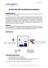
2. Architecture Overview<br />
<strong>UNMS</strong> <strong>II</strong> is an UPS netw ork monitor designed to inform you of emergency power supply<br />
systems problems in your network or the customers network. The <strong>UNMS</strong> uses network<br />
(LAN) connections as default, but allows also connections through MODEM and GSM<br />
Routers (RASMANAGER Analogue and RASMANAGER GSM, requires a<br />
Teleservice/Datacenter license) or “Push Email”. The <strong>UNMS</strong> server service runs<br />
intermittent and checks on UPS devices you specify in a list. When problems are<br />
encountered, the <strong>UNMS</strong> server service can send notifications out to administrative<br />
contacts in a various ways (Email, RCCMD netw ork message, etc. ). Actual status<br />
information, historical logs, and reports can all be accessed via a web-browser (Web<br />
Console).<br />
Figure 1 <strong>UNMS</strong> <strong>II</strong> into a netw ork environment<br />
7<br />
No. Name Description<br />
1<br />
2<br />
3<br />
<strong>UNMS</strong><br />
Server<br />
The <strong>UNMS</strong> server service running on this computer w ith<br />
MS w eb server installation.<br />
Site A user defined group of services (e. g. UPS devices).<br />
Define a name for this group and configure individually<br />
group rules for those devices belonging to this group.<br />
Service A single service (e. g. UPS device w ith CS121 SNMP card<br />
or UPSMAN or BACS) that is monitored by the <strong>UNMS</strong><br />
server.
8<br />
4<br />
Web<br />
Console<br />
3. System Requirements<br />
Web consoles provide sharing of management information<br />
by many people.<br />
The <strong>UNMS</strong> <strong>II</strong> server runs under Windows XP Professional SP3, Windows Server 2003<br />
and 2008, Windows VISTA Business or higher and Windows 7.<br />
The <strong>UNMS</strong> <strong>II</strong> service runs ideally onto a high performance PC. We recommend to use at<br />
least a DualCore CPU w ith 2 GHz and 4 GB RAM. Further we recommend to use a<br />
Windows Server OS than a Windows workstation when monitoring more than 9 devices.<br />
Important: The installation requires administrator privileges and an installed « Microsoft “Internet<br />
Information Serv er (<strong>II</strong>S) » Version 5.0 or higher (<strong>II</strong>S is included into ev ery Windows distribution, but may not<br />
be installed by default. The <strong>UNMS</strong> <strong>II</strong> requires the WorldWideWeb-Service component and the <strong>II</strong>S Manager<br />
Snap-In only).<br />
Web-browser configurations: If y ou are using the Web Console with any web-browser, then it is required, that<br />
your web-browser is supporting XML, Cookies and JavaScript. Additionally y ou should allow « PopUps » from<br />
the IP address of the PC, where the <strong>UNMS</strong> <strong>II</strong> is running.<br />
4. Microsoft <strong>II</strong>S Installation<br />
Any <strong>UNMS</strong> requires the installation of Microsoft Internet Information Server <strong>II</strong>S. The<br />
Teleservice, Datacenter and OPC Versions require additional services to install, these<br />
additional services will described later. Since every <strong>UNMS</strong> requires at least a Microsoft <strong>II</strong>S<br />
Server, the follow ing chapters describe the installations for the supported Windows OS<br />
and w ill continue after this w ith the description of the <strong>UNMS</strong> itself .<br />
4.1 Microsoft <strong>II</strong>S Installation on Windows XP<br />
The support for Windows XP is discontinued after <strong>UNMS</strong> <strong>II</strong> version 2.0.12<br />
If the <strong>II</strong>S is not installed on your OS, you w ill get the follow ing message during the <strong>UNMS</strong><br />
<strong>II</strong> installation.<br />
Figure 2 <strong>UNMS</strong> <strong>II</strong> error message
Click the “Add or Remove Programs” button into the “Control Panel”. Click the<br />
“Add/Remove Windows Components” button. Enable the “Internet Information Services<br />
(<strong>II</strong>S),<br />
Figure 3 Windows Components Wizard<br />
but disable the SMTP Service and click the « Next » button.<br />
Figure 4 Disable SMTP Service<br />
Insert your Windows XP CD and click the “Next” button.<br />
9
Figure 5 Configuring components<br />
Figure 6 Completion<br />
4.2 Microsoft <strong>II</strong>S Installation on Windows 7<br />
If the <strong>II</strong>S is not installed on your OS, you w ill get the follow ing message during the <strong>UNMS</strong><br />
<strong>II</strong> installation.<br />
Figure 7 <strong>UNMS</strong> <strong>II</strong> error message<br />
10
Click the “ Programs” button into the “Control Panel” and click the « Enable/Disable<br />
Windows Features » button. Enable the following features:<br />
Figure 8 Windows Features<br />
Click the « Ok » button to complete the installation and start <strong>UNMS</strong> Setup again.<br />
4.3 <strong>II</strong>S Installation on Windows 2008 Server R2<br />
NOTE : If you want to use the Internet Explorer on this Server for <strong>UNMS</strong>, then you have to<br />
disable the IE Enhanced Security for Windows Server 2003 and 2008 OS.<br />
Here an example of the configuration Internet Explorer IE Enhanced Security (IE ESC) on<br />
Windows Server 2008 R2:<br />
11
Figure 9 Configure IE ESC<br />
Open the “Control Panel” and click the “Turn Windows features on or off” link (below the<br />
“Programs” label) to open the “Server Manager”.<br />
Figure 10 Add Roles Wizard<br />
Open the dialog box “Web Server <strong>II</strong>S” and select “Role Services”.<br />
12
Figure 11 Role Services<br />
Click the « Ok » button to complete the installation and start the <strong>UNMS</strong> Setup again.<br />
Start the <strong>UNMS</strong> setup.exe again, if <strong>II</strong>S problems are solved, the Setup starts now for the<br />
installation of the <strong>UNMS</strong> software.<br />
5. License Regulation<br />
<strong>UNMS</strong> <strong>II</strong> licenses are sold as individual license. A valid <strong>UNMS</strong> license defines the number<br />
of Services (IP addresses) of devices to manage through this <strong>UNMS</strong>. Eg. If you have<br />
purchased a <strong>UNMS</strong> 50 licenses, than max. 50 Services may be managed at a time<br />
through this <strong>UNMS</strong>. Do not install the <strong>UNMS</strong> <strong>II</strong> several times using the same license !<br />
<strong>UNMS</strong> is available also as bundled version, coming w ith UPSMAN or RCCMD software.<br />
This bundled version is limited to 9-nodes and has restricted SNMP functionality. See<br />
Chapter 5.1 below .<br />
You can update any <strong>UNMS</strong> <strong>II</strong> Softw are within 2 years free from the GENEREX w ebsite<br />
www.generex.de. Free update period ends 2 years after installation. After 2 years free<br />
updates are no longer possible and you have to purchase a new version.<br />
5.1 <strong>UNMS</strong> <strong>II</strong> 9-User Bundling License<br />
If you have purchased any RCCMD or UPSMAN software, than this licensekey entitles<br />
you to use the <strong>UNMS</strong> <strong>II</strong> 9-user bundling license, fully functional system, but limited for the<br />
monitoring up to 9 devices (CS121, BACS, UPSMAN and up to 3 non GENEREX SNMP<br />
devices). The commercial version adds features like upgrade, updates, configurable and<br />
customizable screens, up to 5000 Services, teleservice for MODEMs, datacenter<br />
functions for large <strong>UNMS</strong> installations w ith reporting and VPN remote access.<br />
13
5.2 <strong>UNMS</strong> <strong>II</strong> Full Version License<br />
The <strong>UNMS</strong> <strong>II</strong> full version is available from 5 up to 5000 objects or Services (IP addresses)<br />
and offers several modules to upgrade your product until the highest “Datacenter” version.<br />
Follow ing we describe all features of a fully licensed <strong>UNMS</strong> <strong>II</strong> commercial version. If you<br />
miss features in your version than this may be due to a lower licensed version.<br />
If you click into the <strong>UNMS</strong> <strong>II</strong> AdminConsole the menu “Help” and “About”, you w ill get the<br />
information which modules are installed and how many objects/services you can use with<br />
your license.<br />
Figure 12 About <strong>UNMS</strong> Infobox– showing that this Version is for up to 250 Nodes<br />
5.3 <strong>UNMS</strong> <strong>II</strong> Full Version with Teleservice Module<br />
The Teleservice Module is an extension for the <strong>UNMS</strong> w hich provides telephone line<br />
support for analogue modems (RASMANAGER analog) and GSM Routers,<br />
(RASMANAGER GSM). This Module is displayed in the About <strong>UNMS</strong> infobox as “<strong>UNMS</strong><br />
RAS Agent”<br />
14
Figure 13 About <strong>UNMS</strong> Infobox– Version is for up to 25 Nodes and Teleservice<br />
5.4 <strong>UNMS</strong> <strong>II</strong> Full Version License with OPC Module<br />
The OPC Module is a extension for the <strong>UNMS</strong> to w ork as OPC client. This Module is<br />
displayed in the About <strong>UNMS</strong> infobox as “<strong>UNMS</strong> OPC Agent”. Please note that OPC is an<br />
industrial general purpose protocol – any linkage of OPC informations into <strong>UNMS</strong> requires<br />
custom development steps.<br />
Figure 14 About <strong>UNMS</strong> Infobox– Version is for up to 100 Nodes and OPC<br />
5.5 <strong>UNMS</strong> <strong>II</strong> Full Version License with Teleservice/Datacenter<br />
Module<br />
The Datacenter Module is a extension for the <strong>UNMS</strong> to w ork as Datacenter manager.<br />
This module allow s to manage offline installations through “pushmail” (Email) and through<br />
the other connections (Teleservice MODEM, Ethernet, SNMP, OPC server). Additionally<br />
this Datacenter module includes reporting functions and scheduling options to allow an<br />
automated monitoring and alarm forwarding of large installations. This Module is displayed<br />
in the About <strong>UNMS</strong> infobox as “<strong>UNMS</strong> Datacenter”.<br />
6. Getting Started with <strong>UNMS</strong> <strong>II</strong><br />
Although the <strong>UNMS</strong> <strong>II</strong> comes in some cases pre-configured, there are some settings you<br />
have to go through before you can start monitoring.<br />
15
Primarily you have to define, which IP addresses and devices you want to monitor and<br />
which events have to be regarded as alarms. The <strong>UNMS</strong> <strong>II</strong> Admin Console simplifies this<br />
and other <strong>UNMS</strong> <strong>II</strong> related administrative tasks. It is described in the next sections.<br />
The <strong>UNMS</strong> Admin Console is launched automatically after installation has completed. To<br />
start it again later, go to the Windows Start menu and use the Programs/<strong>UNMS</strong>/Admin<br />
Console menu.<br />
7. <strong>UNMS</strong> Admin Console<br />
16<br />
Attention: You need Administrator priv ileges for using the Admin Console !<br />
The <strong>UNMS</strong> <strong>II</strong> is split in 2 parts, the <strong>UNMS</strong> Admin Console, for administrative purposes,<br />
and the <strong>UNMS</strong> w eb-interface, for remote Web access. The Admin Console runs a<br />
Microsoft Internet Explorer embedded in a Window , called Web Console. The Web<br />
Console view is designed through the Site Maps and its related tools Site Explorer and<br />
Event Explorer.<br />
Generally a webbrowser is the graphical interface for all users, who are not working on the<br />
<strong>UNMS</strong> Admin Console and are working and watching the system as it operates.<br />
The <strong>UNMS</strong> Admin Console is for configuration of the <strong>UNMS</strong> <strong>II</strong> screens and the<br />
embedded MS Internet Explorer shows in the Web Console page how the changes would<br />
look, if viewed with a web-browser from remote.<br />
The <strong>UNMS</strong> Admin Console is the toolkit for the <strong>UNMS</strong> <strong>II</strong> Administrator, when doing<br />
changes on the configuration, while the normal monitoring process is usually run through<br />
any web-browser.<br />
7.1 Discover Services<br />
After the <strong>UNMS</strong> <strong>II</strong> is started the first time, the Discover Services w ill be started<br />
automatically to help you finding Services (UPS, BACS, SNMP cards ..) in your local<br />
network environment.
Figure 15 Discover Services<br />
Enter the subnet address, which you want to scan, and enter the IP range (default 1 to<br />
254). If you got additional SNMP devices into your network environment, enable the box<br />
“Search SNMP devices” too and click the “Start Scan” button. If you already know your IP<br />
address and do not want to use Discovery Service, cancel this service.<br />
After the scan is finished, you can allocate the UPS or other objects found in a list and<br />
move them to their Zones/Sites w ith Drag-and-drop. Use the “SHIFT” and “ARROW” keys<br />
to Drag-and-drop several objects at once.<br />
You can choose to use the UPS modelname or the IP address as <strong>UNMS</strong> site/device<br />
name.<br />
17
Figure 16 UPS allocation and moving to Zones/Sites by drag&drop<br />
Click the „Apply“ button to confirm your settings and restart the <strong>UNMS</strong> <strong>II</strong> to use your<br />
configuration changes.<br />
After having the <strong>UNMS</strong> <strong>II</strong> successfully started, you may continue working w ith the <strong>UNMS</strong> <strong>II</strong><br />
Admin Console to complete your settings or to add Sites and Servicesmanually.<br />
7.2 Main Screen<br />
The follow ing diagram and table show the main elements of the Admin Console, when<br />
starting it the first time. (Here w ith user login screen)<br />
18
19<br />
1<br />
2<br />
3<br />
Figure 17 Admin Console – Main Screen<br />
4<br />
No. Name Description Page<br />
1<br />
2<br />
3<br />
4<br />
5<br />
Menu Standard applicati on menu.<br />
Button Bar Provi des shortcut buttons for common tasks and features.<br />
View<br />
Selection<br />
Web<br />
Console<br />
You can switch between Web Console, in which the integrated Web<br />
Browser is displayed, and Site Map s, which allows you to customize<br />
the Web Console.<br />
Display area of the integrated Web Browser, if i n Web Console<br />
mode.<br />
Map Editor Display area of the Site Maps Editor (not in all Editi ons), if i n editor<br />
mode.<br />
Site<br />
Explorer<br />
Event<br />
Explorer<br />
Hierarchical vi ew of all defined sites and their related services<br />
(devices).<br />
Hierarchical vi ew of all defined events and their related command<br />
handlers.<br />
5<br />
Error! Bookmark<br />
not defi ned.<br />
Error! Bookmark<br />
not defi ned.<br />
Error! Bookmark<br />
not defi ned.<br />
Error! Bookmark<br />
not defi ned.<br />
In the following part we explain the configuration options inside the <strong>UNMS</strong> Admin<br />
Console.<br />
7.3 Sites and Services<br />
Sites and Services are managed through the Site Explorer
Site Explorer: The Site Explorer panel is your tool to add, change Sites, add Services,<br />
and form several Sites into Groups.<br />
Figure 18 Admin Console – Site Explorer<br />
Definitons:<br />
Service: A Service is any kind of IP address or hostname, w hich is typical an UPS or<br />
battery system controlled by a CS121 or BACS Webmanger or any other GENEREX or<br />
<strong>UNMS</strong> compatible device like third party SNMP cards. So a Service is the managing<br />
device itself and is always member of a previously defined Site.<br />
Example for a Service: A Service is a managed device like an UPS SNMP card. For<br />
example, a CS121, a BACS Webmanager, a SiteMonitor, the UPSMAN Software or any<br />
RFC 1628 compliant SNMP device are defined as Services.<br />
Site : A Site is a set of well-known Services, like UPS or IP adresses in a certain location.<br />
These locations are called “Sites” and represent the organisational or physial location of<br />
such Services. Any alarm on any Service in this Site w ill change the Site status itself. So<br />
if any of the Services in this Site has an alarm, the Site itself will display this alarm in the<br />
Site Icon.<br />
Example for a Site: You may define the Site “UPS Customer A”. In this Site you have now<br />
e. g. 5 Services running with 5 UPS. This Site may get its individual background and alarm<br />
reactions, if formed into a Group.<br />
7.3.1 <strong>UNMS</strong> <strong>II</strong> Group<br />
Group : A Group is a set of Services belonging together, like a several UPS installation<br />
in the same netw ork or at the same customers organisation.. A Group is defining a set of<br />
Services, w hich in case of alarms will be treated identically. So all devices (UPS,<br />
batteries, etc.) will have the same reactions in case of alarms, if they belong to the same<br />
Group. Through Groups you can define different alarm reactions, e. g. if members of the<br />
Group belong to different organisations.<br />
20
Example for a Group: If in a Group defined as “UPS Group” and added to this Group all<br />
Services, w hich have UPS, than you can define actions, which will apply for all devices in<br />
the Group. So an UPS alarm on any of the devices in this group w ill send an email to the<br />
UPS service center in your organisation, while an alarm in the Group “Batteries” will send<br />
an email to the battery service department in your company.<br />
Through the Site Explorer you configure relationsships of your Services and Sites.<br />
Get into the Site Explorer, click the desired Service button and change the Service<br />
Properties. Open the Group dropdown menu, click on “Edit…” and add the desired group<br />
name.<br />
Figure 19 Service/Event Properties – Edit Group<br />
Repeat this procedure for all Services, that you want to add to a Group. Get into the<br />
Event Explorer and add the desired Event to this new Group. Open the accordant Event<br />
Properties of the Event, that you want to add to the new Group. Open the dropdown<br />
menu under “Match service group”, “Edit…” and add the desired Group. This Event is<br />
valid only for this Group exclusively.<br />
7.4 Events and Priorities<br />
Jobs and Event reactions in the <strong>UNMS</strong> are managed through the Event Explorer.<br />
The <strong>UNMS</strong> shows the Sites and Services on a graphical screen as icons. Such icons<br />
display their status according to the configured priorities. For example, if one service of the<br />
Site runs into as critical defined status while another service of this Site is still in normal<br />
status, then the whole site will be in a critical state and displays this through this higher<br />
priorized icon.<br />
To define w hich events are critical or not, you use the <strong>UNMS</strong> Admin Console tool Event<br />
Explorer.<br />
21
Figure 20 Admin Console – Event Explorer<br />
The Event Explorer panel is your tool to add, remove or change Events.<br />
An event may be an already predefined alarm of a Service like at the alarm “ups on<br />
battery”. There are many predefined events found in the Event Explorer for UPS<br />
(Uninteruptible Pow er Supplies), ATS (Automatic Transfer Sw itches), BACS (Battery<br />
Analyse and Care System), network, alarm contacts, etc., additionally you have also the<br />
option to add more events.<br />
7.4 Starting and Stopping the <strong>UNMS</strong> <strong>II</strong><br />
You have to save and restart the <strong>UNMS</strong> before any of your configurations becomes<br />
effective. You can restart the <strong>UNMS</strong> <strong>II</strong> using the start/stop commands in the <strong>UNMS</strong> <strong>II</strong><br />
Admin Console button bar:<br />
Figure 21 Admin Console – starting/stopping the <strong>UNMS</strong> <strong>II</strong><br />
Restarting or stopping the <strong>UNMS</strong> or rebooting your <strong>UNMS</strong> server computer, is a longer<br />
process and may take several minutes, depending on the size/amount of Sites, Serives<br />
you have configured. When you restart the <strong>UNMS</strong> service, all remote sessions connected<br />
to your monitored devices are logged out, any status and measurement data is<br />
interrupted, all Web Console connections are unavailable until the <strong>UNMS</strong> <strong>II</strong> is restarted.<br />
22
7.5 Working with the Site Explorer<br />
Locate the Explorer Panel on the right side of the console. If you can‟t see the Explorer<br />
Panel, use the View/View Site Explorer menu to show it. Select the first tab marked Site<br />
Explorer. The displayed Sites and Services tree shows all sites and their related<br />
services as defined within your <strong>UNMS</strong>.<br />
Figure 22 Site Explorer<br />
Single-click on the small box to the left of a site icon (building icon) to expand or collapse<br />
that site in the tree.<br />
Left-click on any object name to select that object.<br />
Use the « Delete key » to remove the selected object.<br />
Right-click on a site (building icon) or service icon (gear icon) or name to see the available<br />
context menus.<br />
Open a site tree and use the Edit/Insert Service menus or Button Bar buttons to add<br />
service objects to the site tree.<br />
7.6 Changing Service Properties<br />
Using the Site Explorer tree, expand the site icon (building icon) that contains the service<br />
of interest. Then Right-Click on the desired service icon (gear icon) and use the<br />
“Properties” context menu.<br />
Service Properties General: Enter the service name in the “Name” edit box. This is a<br />
name to identify your device in the <strong>UNMS</strong> <strong>II</strong> listbox and graphical screen.<br />
Service: Click the Service box to disable the monitoring of this service, if currently<br />
unavailable.<br />
23
Choose a Group for this service. „STANDARD“ is default. Define an individual name for a<br />
group to configure group rules for those devices belonging to this group (see Group<br />
configuration later in this manual).<br />
Enter the Service IP address in the “DNS name or IP address” edit box. This can be an IP<br />
address or as DNS name.<br />
Choose the “Connection type”: For UPSMAN Software, CS121, BACS or any other<br />
GENEREX device choose “CS121 compatible (UPSTCP)” and use the default IP port<br />
5769. Other non-GENEREX devices are found as SNMP compatibles in the drop-downlist<br />
box to choose.<br />
Figure 23 Site Explorer – Service Properties – Connection type<br />
For SNMP devices: Choose the appropriate vendor and enter the service community<br />
string in the community edit box (community string is configured on the remote device, as<br />
default select “public”). The default community is “public”!<br />
DNS name or IP address: Enter a hostname or IP address of your Service, eg. The IP<br />
address of your CS121 or SNMP card. At CS121 the default TCP port is 5769, at SNMP<br />
the community string has to be entered in this menu.<br />
Service Properties Info: For each Service you can provide information as plain text or<br />
hyperlink w hich w ill be visible on the <strong>UNMS</strong> graphical screen as INFO button. You can<br />
add, remove or edit text informations for this specific Service, such information is then<br />
displayed on the <strong>UNMS</strong> <strong>II</strong> graphical screen and may help other <strong>UNMS</strong> <strong>II</strong> operators to find<br />
additional informations or instructions for this specific site.<br />
These entries are displayed under the corresponding service behind an INFO button.<br />
24
Figure 24 Site Explorer – Service Properties – Info<br />
You can add further information for every service. If you click the “More customer data…”<br />
button, you can add an email address, which will receive an email, if you enable the<br />
function “Send mail to contract” into the Job Editor.<br />
Figure 25 Site Explorer – Service Properties – Contract<br />
You can add additional information for every service as text or rather hyperlink. These<br />
entries will be displayed below the accordant service.<br />
Service Properties Advanced - Remote Monitor: This is an option if you do not w ant to<br />
use the HTTP default w eb-link of this Service. At GENEREX devices, the like the CS121,<br />
the “landing” HTTP page is predefined. At non-GENEREX devices the Webserver can not<br />
show the standard UPS layout. To change this you may enter here a different web-page to<br />
connect directly to the Webserver page of this Service.<br />
25
Figure 26 Site Explorer – Advanced – Remote Monitor – configured URL to Webserverpage<br />
of an APC Smartnetw ork SNMP Card<br />
The moment a URL is configured in the Remote Monitor, a doubleclick on this Service in<br />
the <strong>UNMS</strong> w ill open the Webpage of this device directly, skipping the default display of a<br />
UPSVIEW or other <strong>UNMS</strong> standard graphical screens.<br />
Service Properties - Advanced - Data Logging : Enable this option to activate a local<br />
log file in the <strong>UNMS</strong> server for this Service and define the interval for updating values (in<br />
minutes). It creates a local logfile for this Service in the <strong>UNMS</strong>. Through this option you<br />
may built up large databases for your Services monitored by the <strong>UNMS</strong>, w ithout the<br />
restriction of local flashrom limitations of SNMP cards.<br />
Please note that you have to restart the <strong>UNMS</strong> to start logging functions.<br />
If this option is enabled you w ill see in the <strong>UNMS</strong> interface a new button “Data charts”.<br />
Click on this button to see the logfile of this Service grafically in the <strong>UNMS</strong>.<br />
26
Figure 27 Data charts button<br />
When Data Logging is enabled, you can use the charts for inspecting the data and get a<br />
long term history of this Service.<br />
Figure 28 Data chart<br />
Service Properties - Advanced - Copy logfile: From the <strong>UNMS</strong> <strong>II</strong> you may also export<br />
the data into a CSV file. Goto copy the data of the local logfile of this Service via „Copy<br />
logfile...“ to any other directory.<br />
27
Figure 29 DataLog as CSV File – Time Reference Variable<br />
The first variable into the CSV file “tref” (time reference) serves as basis point of time<br />
(01.01.1970) for the determination of the current time.<br />
Figure 30 Advanced<br />
Service Properties - Advanced Communication Parameters: To change the timeout default<br />
for SNMP network communication. If you have a slow network connection or SNMP device with<br />
longer timeouts, this may causes constantly alarms because of slow responses to SNMP<br />
requests. You may change these parameters to make the <strong>UNMS</strong> <strong>II</strong> more tolerant at this Service<br />
(IP address) to avoid such false communication error messages. NOTE: This is only function in<br />
Services using SNMP as Connection type.<br />
Check “Let the <strong>UNMS</strong> generate the „upsGeneralFault‟ events” if it is not required to<br />
distinguish between different alarm triggers – Then <strong>UNMS</strong> w ill generate an<br />
„upsGeneralFault‟ for each alarm.<br />
“Separate Sensor Manager events from other events” is a feature only for customized<br />
<strong>UNMS</strong> software w ith SENSORMANAGER, not active in most standard <strong>UNMS</strong>.<br />
7.7 Working with the Event Explorer<br />
The Event Explorer is your tool for the configuration of events and reactions of the <strong>UNMS</strong><br />
<strong>II</strong> monitored Sites and Services.<br />
28
Locate the Explorer panel on the right side of the console. If you can‟t see the Explorer<br />
panel, use the View/View Event Explorer menu to show it. Select the second tab marked<br />
Event Explorer. The displayed Events and Commands tree shows all events and their<br />
related alarms and priorities as defined within your <strong>UNMS</strong>.<br />
Figure 31 Event Explorer<br />
Single-click on the small box to the left of a group icon (file icon) to expand or collapse this<br />
event group in the tree.<br />
Left-click on any object name to select that object.<br />
Use the « Delete key » to remove the selected object.<br />
Right-click on a group (file icon) or event icon (colored box icon) or name to see the<br />
available context menus.<br />
Open an events tree and use the Edit/Insert Event menus or Button Bar buttons to add<br />
event objects to the tree.<br />
7.8 Changing Event Properties<br />
Using the Event Explorer tree, expand the events icon (file icon) that contains the desired<br />
alarm. Then Right-Click on the alarm icon (colored box icon) and use the « Properties »<br />
context menu to add/change jobs as reaction on this event.<br />
29
Figure 32 Event Properties – New Event – Event Priorities<br />
Event Properties Event Identifier: Choose the Event Identifier you want to customize or<br />
to add to your event managed items. Open the Identifier drop-down list box and e. g.<br />
select the event “upsOnBattery”. Default Event Priority is „0: Info“.<br />
The <strong>UNMS</strong> <strong>II</strong> provides the follow ing events, where most of these Events are not activated<br />
by default :<br />
30<br />
Event<br />
ATS Events (Automatic Transferswit ch)<br />
atsSourceBFailure<br />
atsGeneralFault<br />
atsRedundancyLost<br />
atsOutputOverload<br />
atsSourcesAsynchronous<br />
atsStaticSwitchAFailure<br />
atsStaticSwitchBFailure<br />
atsOnStaticSwitchA<br />
atsOnStaticSwitchB<br />
atsOnManualBypassA<br />
atsOnManualBypassB<br />
atSourceAFailure<br />
AUX Events (Auxiliary Contacts at AUX port)
auxPort1<br />
auxPort2<br />
auxPort3<br />
auxPort4<br />
comPin01<br />
comPin06<br />
comPin08<br />
BACS Events (Battery Events when using BACS)<br />
bacsCommunicationLost<br />
bacsVoltageLow<br />
bacsTemperatureHigh<br />
bacsTemperatureLow<br />
bacsResistorHigh<br />
bacsResistorLow<br />
bacsEqualizingError<br />
bacsVoltageWarnHigh<br />
bacsVoltageWarnLow<br />
bacsTemperatureWarnHigh<br />
bacsTemperatureWarnLow<br />
bacsSystemFailure<br />
bacsResistorWarnHigh<br />
bacsResistorWarnLow<br />
bacsStateCharging<br />
bacsStateDischarging<br />
bacs StateDischargingStopped<br />
bacsStateFloatCharging<br />
bacsVoltageFailure<br />
bacsTemperatureFailure<br />
bacsResistorFailure<br />
bacsGeneralAlarm<br />
bacsVoltageDiffHigh<br />
31
acsBatteryBreakerOpen<br />
bacsVoltageHigh<br />
Device Events (Common Device Events)<br />
devCommon<br />
devWarning<br />
devCritical<br />
RAS Manager (Teleservice RASMANAGER Events)<br />
rasOutConnecting<br />
rasOutConnected<br />
rasOutFailure<br />
rasInConnected<br />
rasOutAutoConn ected<br />
Redundanz Ereignisse<br />
grpOnBattery<br />
grpAutonomy20Min<br />
grpAutonomy15Min<br />
grpAutonomy10Min<br />
grpAutonomy5Min<br />
grpRedundancyLost<br />
grpRedundancy05Pc<br />
Sensor Events<br />
sensorHigh1<br />
sensorHigh2<br />
sensorHigh3<br />
sensorHigh4<br />
sensorHigh5<br />
sensorHigh6<br />
sensorHigh7<br />
sensorHigh8<br />
sensorLow1<br />
sensorLow2<br />
32
sensorLow3<br />
sensorLow4<br />
sensorLow5<br />
sensorLow6<br />
sensorLow7<br />
sensorLow8<br />
SiteManager Events (Sitemanager multiple Alarms)<br />
sman2AnalogInput01<br />
sman2AnalogInput02<br />
sman2AnalogInput03<br />
sman2AnalogInput04<br />
sman2AnalogInput05<br />
sman2AnalogInput06<br />
sman2AnalogInput07<br />
sman2AnalogInput08<br />
sman2DigitalOuput01<br />
sman2DigitalOuput02<br />
sman2DigitalOuput03<br />
sman2DigitalOuput04<br />
sman2DigitalOuput05<br />
sman2DigitalOuput06<br />
sman2DigitalOuput07<br />
sman2DigitalOuput08<br />
sman2IoMarker01<br />
sman2IoMarker02<br />
sman2IoMarker03<br />
sman2IoMarker04<br />
sman2IoMarker05<br />
sman2IoMarker06<br />
sman2IoMarker07<br />
sman2IoMarker08<br />
33
SiteMonitor Events (Sitemonitor Digital Alarms)<br />
smon2DigitalInput01<br />
smon2DigitalInput64<br />
smon2IoMarker01<br />
smon2IoMarker16<br />
System Events (<strong>UNMS</strong> system alarms and<br />
notifications)<br />
nmsStarted<br />
nmsStopped<br />
nmsAckByUser<br />
nmsCmdByUser<br />
netConnectionLost<br />
netParseError<br />
UPS Events (UPS alarms and events)<br />
upsModelUnknown<br />
upsBatteryBad<br />
upsBypassBad<br />
upsOutputOffAsRequested<br />
upsOffAsRequested<br />
upsChargerFailed<br />
upsOutputOff<br />
upsSystemOff<br />
upsFanFailure<br />
upsFuseFailure<br />
upsGeneralFault<br />
upsDiagnosticTestFailed<br />
upsOnBattery<br />
upsCommunicationLost<br />
upsAwaitingPower<br />
upsShutdownPending<br />
upsShutdownImminent<br />
upsTestInProgress<br />
34
upsBatteryCharged<br />
upsDieselOnLoad<br />
upsDieselAvailable<br />
upsEssentialBusBad<br />
upsGenEssentialBusBreakerClosed<br />
upsLowBattery<br />
upsInputBreakerClosed<br />
upsBypassBreakerClosed<br />
upsEssentialBusBreakerClosed<br />
upsDCDCConverterOn<br />
upsManualBypassClosed<br />
upsEssentialBusOverload<br />
upsOutputBreakerClosed<br />
upsSecondsOnBattery<br />
upsEstimatedMinutesRemaining<br />
upsDepletedBattery<br />
upsTempBad<br />
upsInputBad<br />
upsOutputBad<br />
upsOutputOverload<br />
upsOnBypass<br />
Event Properties Actions Display Name. Enter the name for this event in the Display<br />
Name edit box. This Name w ill be displayed to identify your configured job in the <strong>UNMS</strong> <strong>II</strong><br />
logfilesEvent Properties Event Priority: Choose the event priority from the Event<br />
Priority drop-down list for this new name and the corresponding event. This defines the<br />
colour of the icon in the <strong>UNMS</strong> <strong>II</strong> graphical screen.<br />
Event Properties Log Message: You can customize the message that is printed in the<br />
event log. Default is “$(EVENT)”, w hich is writing only the standard event name into the<br />
logfile. You may add now more log entries by choosing these from the drop-down list (see<br />
fig. 24).<br />
Event Properties Run a job: Choose the job to execute from the Run a job dropdown<br />
list and add a desired delay in seconds into Delay actions:. To create a new kind of job or<br />
35
change an existing one, select or from the Run command dropdow n<br />
list (see chapter 7.9 Changing Job Properties).<br />
Event Properties Filters/Match service group: Select a specific service group to match<br />
this event. Select “ANY” to match all target services.<br />
Some events like „upsEstimatedMinutesRemaining“ provide the functionality to define a<br />
threshold (Evaluate condition). The actions will be executed if this threshold is reached.<br />
Figure 33 Event Properties – New Event – Evaluate condition<br />
In Figure 31 the Event Identifier is „upsEstimatedMinutesRemaining“. Actions described<br />
below (set color to “Critical”, log Message $(Event), run a job “Default”) and “ANY” Group<br />
member w ill use these settings if the value „upsEstimatedMinutesRemaining“ is less than<br />
5 (Minutes).<br />
7.9 Changing Job Propertie s<br />
You can change Job Properties within the Event Properties dialog. Choose the job name you<br />
want to change from the Jobs list or click the Add button to add a new customized job.<br />
36
Figure 34 Event Properties – New Event – Run a Job – create or edit a new Job<br />
Check the Write to log file box, if this event should be written to the <strong>UNMS</strong> Event Log file<br />
(default is on).<br />
Check the Show local Alarm box if this event should be displayed in the local Alarm Box of the<br />
<strong>UNMS</strong> server.<br />
To send an email when this Event occurs, click the “…” button behind the “Send Email” row and<br />
enter the accordant email recipients.<br />
Figure 35 Email-Addresses – List of Recipients<br />
Note: To enable Send Email, you must first configure the outgoing mail server in the Email<br />
page under the Tools/<strong>UNMS</strong> Options menu.<br />
Run RCCMD: This is a shutdown and messaging tool to remotely shutdown computers or send<br />
messages. To run RCCMD, w hen an event occurs, click the „…‟ button on the left of the Run<br />
RCCMD edit box. In the following dialog you can enter the RCCMD arguments for 1 or more IP<br />
addresses or RCCMD hostnames.<br />
37
Figure 36 RCCMD Configuration<br />
As a result on your RCCMD clients a messagebox will appear (see below) or a shutdown will be<br />
executed. For more details about RCCMD functionality, please use the RCCMD user manual.<br />
Figure 37 <strong>UNMS</strong> Alarms Message Box<br />
To run multiple RCCMD shutdowns or messages or to use broadcast, use the listbox or reopen<br />
the RCCMD configuration to add more RCCMD clients.<br />
To run an external program w hen an event occurs, click the „…‟ button on the left of the<br />
Run Program edit box. In the follow ing dialog you can enter the program name and zero<br />
or more program arguments.<br />
Figure 38 External Program<br />
38
7.9.1 Configure RCCMD Server Jobs<br />
Using the Event Explorer tree, expand an events icon (file icon), that contains the alarm of<br />
interest. Then Right-Click on any of the alarm icons (colored box icon) and use the<br />
Properties context menu to open the Event Properties dialog.<br />
Select “” under Run job to open the “Job Editor” dialog (see below)…<br />
Now select a Job or create a „[New job]“ in the Event Properties for the desired Events<br />
that should trigger the RCCMD command.<br />
Figure 39 Event Properties – Run a job<br />
To configure a RCCMD command directly, click the „...“ button behind Run RCCMD.<br />
You can enter the accordant IP address/host name and the port. Furthermore you can<br />
enable SSL. The functions „Send Shutdown command“ and „Send message“ are at hand.<br />
Figure 40 Job Editor – Run RCCMD – RCCMD configuration<br />
39
8. Customizing <strong>UNMS</strong><br />
Note: The Site Maps function is not available in all editions. In addition Site Maps views are not liv e<br />
views ! You have to save and restart the <strong>UNMS</strong> to see the changes in the <strong>UNMS</strong> webserver !<br />
8.1 Working with Site Maps<br />
Locate the View Selection on the top of the console. Select the second tab marked Site Maps.<br />
The displayed editor screen shows the background and the layout of all site icons as they will be<br />
displayed later in a Web Console.<br />
Figure 41 Site Maps – Europe Card<br />
No. Name Description<br />
1<br />
2<br />
3<br />
40<br />
Editor Tab Click on the Site Maps tab to switch to the editor mode.<br />
View Sel ection Click the Sit es button to switch to the mai n screen.<br />
Screen<br />
Designer<br />
Click the Services button to switch to the services list.<br />
Here you can layout the site icons by dr ag-and drop operations, add new sites and change<br />
existi ng site pr operties.<br />
Left-click on any object icon to sel ect that object.<br />
Use the Delete key to remove the sel ected object.<br />
Right-click on a site icon to see the available context menus.<br />
Double-click on a site icon to switch to the ser vice list vi ew mode.<br />
For how to set Sit e Maps properties, see Setting Editor Options.
8.2 Sub-Screen Editing<br />
The <strong>UNMS</strong> <strong>II</strong> provides to create several sub-menus, e. g. a screen as main page and several<br />
other screens as sub-screens. Please do the following to edit such sub-screens.To build a subscreen<br />
use the “Edit menu” and click “New Site…”.<br />
Enter the name into the “Site name” box.<br />
Check the box Background image file. In this example the “Europe.png” file was<br />
selected w ith the “Browse…” button, which is integrated in the <strong>UNMS</strong> <strong>II</strong>.<br />
Figure 42 Site Maps – New Site – Background image file<br />
Build a new site on the sub-screen eg. “europe” with the function “New Site…”. In this example<br />
the sub-screen “Hamburg” is following. A graphic file type PNG w ith the desired background has<br />
to be copied into the directory C:\UPS\unms<strong>II</strong>\www\image\. The size of the PNG file depends<br />
on the resolution of your display. To have a perfect screen you may resize you pictures.<br />
On the sub-screen “<strong>Generex</strong> Headquarter” the sub-screens “HW121, HW131, BACS” were built.<br />
Behind this sub-screens determine services. In this section you can build the objects (e.<br />
g. UPS) via the Site Explorer w ith the “New Service” function.<br />
Figure 43 Site Properties – New Site – Web Console View<br />
41
The status of the services will be displayed via the icons on every sub-screen. The colours of the<br />
status will be combined displayed on the overlaying sections, so that an ANY alarm in the screen<br />
of “HW131” will be displayed on the section “europe” with a red LED.<br />
Save your settings and restart the <strong>UNMS</strong> <strong>II</strong>.<br />
Figure 44 Web-Browser – LogFile<br />
Advice: It is required to create all Sites at first and to select the desired background pictures. As far<br />
as a Service is defined, it is not possible to change the background anymore!<br />
9. <strong>UNMS</strong> Options<br />
Note that the Site and following page are not available in all Editions.<br />
Figure 45 <strong>UNMS</strong> Options<br />
9.1 <strong>UNMS</strong> Options - Editor<br />
In the <strong>UNMS</strong> Options you may change backgrounds, configure Email, setup login and<br />
passwords, configure Logging options and setup <strong>UNMS</strong> System settings<br />
Use the Browse… button to locate a background image for the Web Console main screen.<br />
Note that the image must be in the <strong>UNMS</strong> image directory. Not in all Editions: Choose the stripe<br />
set for the site icons in the Web Console from the Map site icon stripe drop-down list.<br />
Select the Hide the site icon labels box to hide the icon text labels in the Map Editor view.<br />
42
Press the OK button to save your changes.<br />
9.2 <strong>UNMS</strong> Options - Email<br />
To send out Emails from the <strong>UNMS</strong> you have to setup an email account and configure it in the<br />
Email menue:<br />
Click the Enable Email Client box to activate the Email Client for the <strong>UNMS</strong>.<br />
Set the Outgoing Server (SMTP) to the IP address of your Email server.<br />
Set the Sender Email Address to an Email address that is valid at the server above.<br />
Click the Use Authentication box if the server from above requires user authentication.<br />
Enter the authentication user name and related password in the appropriated edit boxes.<br />
Figure 46 <strong>UNMS</strong> Options - Email<br />
Press OK to save the changes. To check the email function, restart the <strong>UNMS</strong> <strong>II</strong> service<br />
after configuration. For testing purpose you may configure the EVENT “<strong>UNMS</strong> Started” to<br />
send an email, or you may or use the Windows Commandline and enter commands for the<br />
email tool “qblat” manually. Qblat is stored into the folder C:\UPS\unms<strong>II</strong>, syntax is as<br />
follows: Open a “cmd-w indow” and enter the following parameter: qblat –u (username) –<br />
pw (password) –t (email addresss of the receiver) test<br />
Figure 47 <strong>UNMS</strong> Options – Email – Email test w ith qblat<br />
43
If you read “Sending stdin.txt to Login name is and no futher error<br />
messages, than you should find this email “test” in your mailbox.<br />
9.3 <strong>UNMS</strong> Options – Email Traps<br />
The Email Trap feature provides the transfer of the device data via POP protocol to the<br />
<strong>UNMS</strong> <strong>II</strong> service. You can configure the connection type, like the other ones (UPSTCP,<br />
SNMP, RAS), into the AdminConsole. This function is available into the Data<br />
Center/TeleService Edition (optional software extension for the <strong>UNMS</strong> <strong>II</strong>) only.<br />
This agent can assimilate incoming data (incoming email traffic) only in contrast to the<br />
other agents, but might be the optimal fitting for relevant o security customers and remote<br />
monitoring.<br />
For the usage of the Email Traps are the follow ing conditions required:<br />
44<br />
Email box/user is an email account for all devices, which w ill be monitored via<br />
Email Trap<br />
Email transfer protocol: POP<br />
Email data type: JSON data as attachment must be accredited<br />
Configuration mail server: Global email configuration must be equipped (see<br />
chapter 9.2)<br />
Configuration email client: As connection type per device into the <strong>UNMS</strong> <strong>II</strong>.<br />
The settings will be described as follows:<br />
Figure 48 <strong>UNMS</strong> Options – Email Traps – Account settings<br />
Enter the accordant incoming server (POP3), the user name and the password. Click the<br />
“Advanced settings…” button for further settings, which are required for your mail server.
Figure 49 <strong>UNMS</strong> Options – Email Traps – Advanced Settings<br />
Click the “Check settings” button to check the connection to your mail server. You should<br />
get the message “Connection to POP3 server successful” after a couple of seconds.<br />
Now add some devices, which should be monitored via Email Trap:<br />
Figure 50 <strong>UNMS</strong> Options – Email Traps – Service Properties<br />
Select the connection type “E-Mail Traps” and enter the accordant MAC address of the<br />
CS121.<br />
45
Figure 51 <strong>UNMS</strong> Options – Email Traps – Service Properties – MAC address<br />
The interval of the “<strong>UNMS</strong> <strong>II</strong> Heartbeat” will be defined at the CS121. The “<strong>UNMS</strong> <strong>II</strong><br />
Heartbeat” is a regularly sent email, w hich transfers the status of the device. If the email<br />
will not be received, the <strong>UNMS</strong> <strong>II</strong> w ill trigger a w arning. If no alarms w ill occur, the <strong>UNMS</strong><br />
<strong>II</strong> heartbeat email will send the latest measuring values regularly.<br />
Every grafical UPS/device screen contains a timestamp, which displays the last incoming<br />
Email Trap or <strong>UNMS</strong> <strong>II</strong> Heartbeat.<br />
Figure 52 <strong>UNMS</strong> Options – Email Traps – Screen w ith timestamp<br />
46
Every alarm triggers beside the regular <strong>UNMS</strong> <strong>II</strong> Heartbeat a further one, which will be<br />
sent immediately. This means, that the display is always up to date at alarm states, but will<br />
be updated in normal operation just in higher intervals (see timestamp). Advice: A direct<br />
connection via web-browser, like at netw orks, is not possible, this button is not at<br />
present into this display. If you want to log the measuring values, it is required to enable<br />
the datalog function into the <strong>UNMS</strong> <strong>II</strong> (see chapter 7.6).<br />
9.4 <strong>UNMS</strong> Options – Users<br />
With user management you can restrict and audit user capabilities and actions. There are three<br />
predefined users: admin, operator and guest. The predefined passwords are equal to the user<br />
name, for example „admin‟ for the admin user.<br />
To disable access control, click the Anonymous Access box (not recommended). Click the<br />
New button to add a new user account. Click the Properties button to change an existing user<br />
account. Click the Delete button to delete an existing user account (Note that the predefined user<br />
admin can not be deleted).<br />
Figure 53 <strong>UNMS</strong> Options – Users – User Properties<br />
Note on groups: The users group defines the access level as follows:<br />
47<br />
Administrators: Full access to all <strong>UNMS</strong> capabilities.<br />
Operators: Full access from Web-Console, but no access to Administrator Console.<br />
Users: Read-only access from Web Console<br />
9.4.1 <strong>UNMS</strong> Options – Secure Settings<br />
Advice: The Secure settings function and the following menu are available with the TeleService<br />
Modul only.<br />
The Administrator can control or rather allocate the access authorization of the Sites to<br />
groups via Secure settings. The sub sites inherit the authorization of the Site
automatically. You can see in the following example, that a group „Hamburg“ was created,<br />
which should be authorized for the group members Hamburg and Administrators.<br />
Figure 54 <strong>UNMS</strong> Options – Users – Secure Settings<br />
Thereby it is secured, that the group Hamburg (and Administrators) get access to the Site<br />
Hamburg and its sub-sites “Nord” and “Süd” only. The other Sites BACS, CS121, Email<br />
Traps, Facility Management and Foreign Devices, as you can see in the above example,<br />
are not apparent for the group Hamburg.<br />
Figure 55 <strong>UNMS</strong> Web Console – Login Group Hamburg – Start Screen<br />
48
9.5 <strong>UNMS</strong> Options – Logging<br />
Under Event log file schedule you can save log files for different periods of time. They can<br />
contain Event logs for a day, a week, a month or a specific amount of memory. If you want to<br />
save several days, weeks etc. you have to change the Number of old logs to keep accordingly.<br />
Figure 56 <strong>UNMS</strong> Options – Logging<br />
Under Data log file schedule you can save log files for different periods of time. They can<br />
contain Data logs for a day, a week, a month or a specific amount of memory. If you want to<br />
save several days, weeks etc. you have to change the Number of old logs to keep<br />
accordingly.<br />
9.6 <strong>UNMS</strong> Options – System<br />
On the System page it is possible to modify the TCP port, the refresh rate, check interval and the<br />
service lost delay by clicking the box.<br />
Figure 57 <strong>UNMS</strong> Options – System<br />
49
10. Configuration Backup and Restore/Software Update<br />
To allow <strong>UNMS</strong> updates and for not to loose your configurations we strongly recommend<br />
to save a <strong>UNMS</strong> backup file whenever you make changes. With this backup file you may at<br />
anytime remove and reinstall or update your <strong>UNMS</strong> software and load the configuration<br />
later afterwards again.<br />
In the “<strong>UNMS</strong> Administrator” Program open the “File” menu and choose the “Backup…”<br />
item to open the “Backup files” Dialog.<br />
In the field for “Backup to” enter a Name for your Backup (In this example w e used<br />
“newBackup”).<br />
Click the button to save a backup of the configuration under this name.<br />
Figure 58 <strong>UNMS</strong> Backup – Backup files<br />
In the “<strong>UNMS</strong> Administrator” Program open the “File” menu and choose the “Restore…”<br />
item to open the “Restore files” Dialog.<br />
Select the name of the Backup that you to restore from the list of available Backups (In this<br />
example w e used “new Backup”). Click the button to restore the selected<br />
backup of the configuration.<br />
The follow ing message request your confirmation to use the backup as the current<br />
configuration. Click the button to restore the configuration from above.<br />
Please note that you must restart the <strong>UNMS</strong> before this configuration changes (the<br />
backup) take place.<br />
50
Figure 59 <strong>UNMS</strong> Restore – Restore files<br />
If you want to update the <strong>UNMS</strong> <strong>II</strong> version, it is required to deinstall the old version, install the<br />
current <strong>UNMS</strong> <strong>II</strong> version and to use the „Restore“ function for the usage of the desired<br />
configuration.<br />
11. <strong>UNMS</strong> Redundancy Configuration<br />
The <strong>UNMS</strong> redundancy configuration is an optional feature of the <strong>UNMS</strong> and requires and<br />
additional license upgrade. If you do not use the Redundancy <strong>UNMS</strong> Version, you may skip this<br />
chapter and continue with the follow ing Chapter 12. <strong>UNMS</strong> redundany is useful if you should<br />
have devices/sites which are working in a redundant mode, eg. a 2 UPS which are having their<br />
own SNMP or CS121/BACS manager, but working in parallel and redundant. If one of these 2<br />
UPS w ould stop working, running on battery, etc. (any EVENT is possible) you may not want to<br />
execute shutdowns or major alarms. In such a situation it may be useful to define that only minor<br />
alarms / jobs are started if the other UPS is still running fine. For such a configuration you may<br />
use the Redundancy configuration described in the following chapter.<br />
Open the Redundancy configuration via “Tools” into the Administrator Console. The configured<br />
services/devices in your <strong>UNMS</strong> will appear in a list box.<br />
Figure 60 <strong>UNMS</strong> Redundancy Configuration<br />
Mark a service and click the „Configure service...“ button to get into the Service redundancy<br />
configuration.<br />
51
Choose now the Services in your configuration where you have a parallel redundancy situation<br />
and move these to the windows “Services selected for the Redundancy Group” and choose<br />
the redundancy level.<br />
Click on “Configure redundant service” to configure the Events on these devices that may<br />
have an effect on the system they are backing up. Typical risks are overload situations on a<br />
single Service which would not be seen as long as the system runs in parallel and the load is<br />
distributed between the other UPS in the group. But if one or more Redundancy Group members<br />
should fail, than it could be possible than ALL the load has to be burdened by the remaining UPS<br />
– which could be too much. To avoid this situation you may want to configure an “redundancy<br />
lost alarm” in case the load in the group would exceed that amount a single device could supply.<br />
For this setup you have to define the redundancy level of this Redundancy Group.<br />
In the following we describe as an example the configuration for a setup of 2 UPS w hich are in<br />
parallel and redundant. In case one of the 2 UPS load increases more than 50% and overload<br />
condition could make also the second UPS fail. To avoid this situation is may be important to<br />
watch the load on both UPS and trigger an alarm if the load should increase on one of the 2 of<br />
more then 50%.<br />
Since there are just 2 UPS in the Redundancy Group, the redundancy level can be only “1”.<br />
One of the 2 UPS may fail and the remaining one is capable to supply the load. (“0” would mean<br />
“no redundancy” – this would be identical as if you configure a single Service, no redundancy at<br />
all).<br />
By choosing 2 UPS as the Redundancy Group the redundancy lost alarm threshold is<br />
automatically set to 50% on each. If you choose 3, the <strong>UNMS</strong> automatically lowers the level to<br />
33.33% of the redundancy level is 1. At a higher redundancy level the load level would<br />
automatically increase. So the automatic alarm threshold load parameter is set be the <strong>UNMS</strong><br />
through the number of Services in the Redundancy Group and the redundancy level.<br />
All events will appear into the left section as Available events, which have been previously<br />
configured into the Event Explorer or are default. Alike the example with individual Service LOAD<br />
you may configure other Events.<br />
Enter the true power of the UPS into „Nominal Ouput Power (in kVA)“. Therefore the <strong>UNMS</strong> <strong>II</strong><br />
is able to calculate by itself, if a shutdown is really required, in case the load is increasing. The<br />
more parallel redundant systems you define, the more the load value for a single device will<br />
decrease. E. g. if you have 3 UPS in parallel redundancy, than the load per single UPS would be<br />
33.33%, etc.<br />
52
Figure 61 <strong>UNMS</strong> Redundancy Configuration – Redundant Service Configuration<br />
In the EVENTs you will find now new events, the Redundancy Events. The following special<br />
Redundancy Events events are available:<br />
53<br />
grpOnBattery – The redundancy is lost, both UPSs are actually running on battery.<br />
grpAutonomy20Min – The redundancy is lost. The UPS in the redundancy Group<br />
with the lowest autonomy time is the one that determines if this event is TRUE. If<br />
during a battery operation any of redundancy Group members are reading an<br />
autonomy time of less than 20 minutes, the defined job will be executed.<br />
grpRedundancyLost – The redundancy is lost. This is a warning and should tell you<br />
that actually the load of the redundant system is too high for the configured<br />
redundancy level. If in this situation one of the group members would fail, the<br />
remaining Services could be in an overload situation. This event is designed to warn<br />
the user of such a situation.<br />
grpRedundancy05Pc – The redundancy is lost. This job will be executed, if the<br />
overall load is more than 95% on every single phase. Only 5% load reserve is<br />
avaiblabe now. This is an option for a a « Pre-Warning » of the above described<br />
« grpRedundancyLost » event.
Figure 62 <strong>UNMS</strong> Redundancy Screen of 2 UPS, show ing the reserve power on each<br />
phase.<br />
12. <strong>UNMS</strong> Configuration of RASMANAGER<br />
The <strong>UNMS</strong> RASMANAGER configuration is for the use of RASMAN_A – analogue<br />
Modem Dial-in/Dial-Out and requires a « Teleservice » license. If you do not use the<br />
RASMAN_A , you may skip this chapter and continue with the following Chapter 13.<br />
Please note, that the RASManager is not compatible with Windows VISTA and<br />
Windows 7 yet. To work w ith RASMANAGER you have to purchase the « <strong>UNMS</strong><br />
TELESERVICE MODULE » as license upgrade for your existing <strong>UNMS</strong> license. Please<br />
note, that any <strong>UNMS</strong> optional module is only w orking w ith commercial versions of the<br />
<strong>UNMS</strong>, not w ith any free <strong>UNMS</strong> license.<br />
To integrate RASMANAGER devices in the <strong>UNMS</strong> monitoring, you have to setup the<br />
RASMANAGER first. How to setup a RASMANAGER is described in the CS121 user<br />
manual, follow ing an abstract of this manual.<br />
You may skip this chapter, if your RASMANGER has been already installed.<br />
54
The configuration of RASMANAGER / <strong>UNMS</strong> is found in the menu under<br />
« Configuration ».<br />
Figure 63 <strong>UNMS</strong> RAS Configuration<br />
Please note, that this function requires a RASMANAGER license key w hich is optional for<br />
CS121 and BACS systems (only included per default in a RASMANAGER).<br />
Configure/Select the accordant UPS model in your RASMANGER and define the<br />
parameter of the LAN interface for the connection at the customers network.<br />
The usage of the LAN interface is optional and is not required for the modem connection.<br />
If no customers network is present, you can accomplish the follow ing settings from a<br />
notebook via cross-cable. Assign the IP address 10.10.10.11 for your notebook.<br />
For setting up a CS121 or BACS system, please refer to the user manual of these<br />
devices. We describe here only the RASMANAGER related parts .<br />
For the configuration of the connection settings of the modem operation, please get into<br />
the „RAS Configuration“ menu.<br />
55
12.1 RAS Client Settings<br />
Figure 64 RAS Manager Settings 1<br />
At first enable the „RAS Client“ (1). The client is the module, w hich will establish the<br />
connection to the <strong>UNMS</strong> <strong>II</strong> w orkstation.<br />
Enter the number of the modem (2) of the <strong>UNMS</strong> <strong>II</strong> w ith Teleservice Module. Please note,<br />
that in some telephone system a prefix number (e.g. 0) is may be required to get an<br />
outside line.<br />
Enter the IP address of the RAS server for incoming calls from the <strong>UNMS</strong>. This IP adress<br />
will be active the moment a <strong>UNMS</strong> dials into the RASMANGER. It w ill be a different IP<br />
adress than the one this device would have if running in your LAN. This IP adress has to<br />
accessible from the <strong>UNMS</strong> via MODEM and therefore has to be configured also on the<br />
<strong>UNMS</strong> side as „Destination Address“ (3). This address will be defined later into the <strong>UNMS</strong><br />
Teleservice Module and should be set to ALL RASManagers monitored by this <strong>UNMS</strong>.<br />
It is required to set a „Username“ (4), which has to be different for every single<br />
RASManger (e.g. UPS1, UPS2 etc.). The Password (5) may be identical, but the<br />
username MUST be different and later configured in the <strong>UNMS</strong> Teleservice Module.<br />
56
Figure 65 RAS Manager Settings 2<br />
Enable the „RAS Server“ (1). The server receives incoming calls from the <strong>UNMS</strong> <strong>II</strong><br />
workstation. If you do not want to allow that <strong>UNMS</strong> dials in (only dial out for alarms), you<br />
may deactivate the server. In this case the RAS server will trigger alarms to the <strong>UNMS</strong> <strong>II</strong><br />
workstation only, but <strong>UNMS</strong> can not dial back to check the actual situation.<br />
It is required to enter a „Server IP Address“ (2) at the different RASManagers to be able to<br />
differentiate the connections (e.g. UPS1 = 192.168.10.11, UPS2 = 192.168.10.12 etc.).<br />
You can use the same „Password“ (4) for all RASManagers.<br />
To finish the RAS configuration successful, it is required to set the „COM2 Mode“ to „RAS“<br />
into the „COM2 & AUX“ menu. You can use the default values f or the baud rate and the<br />
parity.<br />
Figure 66 COM2 Settings – RAS<br />
12.2 Configuration of the Events for Modem “Dial-Out”<br />
The operator can define via „Event Configuration“, for which alarm a message should be<br />
triggered to the <strong>UNMS</strong> <strong>II</strong> w orkstation.<br />
To trigger a <strong>UNMS</strong> dialout message at an overload, it is required to select the function<br />
„Send RAS Notification“ (1) into the event „Overload“.<br />
57
Figure 67 Job Editor<br />
You can enter any text into the w indow „Message“ (2). In this example this text will be<br />
transferred to the <strong>UNMS</strong> only if the event « Overload » is active for more than 60 seconds.<br />
To finish the configuration of the RASManager, it is required to save your settings via the<br />
menu „Save Configuration“, „Save, Exit & Reboot“. After the RASManager has rebooted<br />
(status LED is flashing green), put the DIP-Sw itch into the position „On“ to integrate it now<br />
into your network and to leave the configuration mode and reboot it again. (Unplug the<br />
pow er supply for about 3 seconds. ) After the RASMANAGER has rebooted you see a<br />
green flashing LED and you can continue now to configure your <strong>UNMS</strong> TELESERV ICE<br />
settings.<br />
12.3 Configuration of the <strong>UNMS</strong> <strong>II</strong> Workstation for incoming Dial<br />
Connections (Windows XP, SP2)<br />
58<br />
!!! The support for Windows XP w as dropped since <strong>UNMS</strong> <strong>II</strong> version 2.0.12 !!!<br />
If your <strong>UNMS</strong> runs on a Windows XP, some settings have to be made on the XP system<br />
to make RAS service available.<br />
The Windows internal RAS server is used for the receiving of incoming connections of<br />
UPS. Get into the netw ork connection via the control panel and click the „Create New<br />
Connection“ button.
Figure 68 Connection Wizard<br />
Click the „Next“ button and select the „Set up an advanced connection“ option.<br />
Figure 69 Connection Wizard – New Connection Type<br />
Select the „Accept incoming connections“.<br />
Figure 70 Connection Wizard – Advanced Connection Options<br />
Select the desired modem out of the device list.<br />
59
Figure 71 Incoming Connection Properties<br />
Enable the option „Do not allow VPN connections“.<br />
Figure 72 Incoming Virtual Private Netw ork (VPN) Connection<br />
For the determination of the incoming calls, it is required to create an own user for every<br />
UPS. Click the „Add“ button.<br />
60
Figure 73 User Permissions<br />
The „Username“ and „Password“ have to be the same ones as for the RAS client of the<br />
RASManager.<br />
Figure 74 New User<br />
Now it is required to enter the IP addresses, which will be assigned from the server during<br />
the dial-in. Enter the „Destination Address“ as starting address, e.g. 192.168.199.1 (1).<br />
If you have set only one modem for dial-ins, it is enough to set an address range till<br />
192.168.199.2 (2), but it is possible to set a w ider range (192.168.199.30). In this case, it<br />
would be possible, if you are using several modems, to receive 30 connections at the<br />
same time.<br />
61
Figure 75 Incoming TCP/IP Properties<br />
12.4 Configuration of the <strong>UNMS</strong> <strong>II</strong> Workstation for incoming Dial<br />
Connections (Windows Server 2003)<br />
If your <strong>UNMS</strong> runs on a Windows Server 2003, some settings have to be made on the<br />
W2003 system to make RAS service available.<br />
The Windows internal RAS server is used for the receiving of incoming connections of<br />
UPS. Get into the Routing and Remote Access menu via the Administrative Tools. Enable<br />
the Routing via the context menu.<br />
Figure 76 Routing and Remote Access<br />
62
Figure 77 Routing and Remote Access Server Setup Wizard<br />
Select the « Remote access (dial-up or VPN) « option.<br />
Figure 78 Routing and Remote Access Server Setup Wizard Configuration<br />
Select « VPN ».<br />
63
Figure 79 Routing and Remote Access Server Setup Wizard Configuration, VPN<br />
Select the network interface.<br />
Figure 80 Routing and Remote Access Server Setup Wizard Configuration, VPN<br />
Connection<br />
64
Figure 81 Routing and Remote Access Server Setup Wizard Configuration, Network<br />
Selection<br />
Select « From a specified range of addresses ».<br />
Figure 82 Routing and Remote Access Server Setup Wizard IP Address Assignment<br />
Enter the desired IP range.<br />
Figure 83 New Address Range<br />
65
Select “No”, if you do not use a RADIUS server.<br />
Figure 84 Routing and Remote Access Server Setup Wizard IP – Multiple RAS<br />
Figure 85 Routing and Remote Access Server Setup Wizard Completion<br />
Now you server is enabled as remote access server.<br />
It is required to configure the authentification method « Unencrypted password (PAP) ».<br />
Click w ith your right mouse button (context menu) on your server into the « Routing and<br />
RAS » menu. Select « Properties » and click the « Authentication Methods… » button.<br />
66
Figure 86 Local Properties<br />
Figure 87 Authentication Methods<br />
Please note, that all other authentification methods have to be disabled!<br />
67
Figure 88 Routing and Remote Access GX206 (local)<br />
It is required to create a new remote access policy. Right-click on Remote Access Policy<br />
and select « New Remote Access Policy ».<br />
Figure 89 Routing and Remote New Remote Access Policy<br />
Select « Set up a custom policy » and enter the desired name.<br />
68
Figure 90 New Remote Access Policy Wizard – Select Attribute<br />
Select the attribute « NAS Port-Type, Async (Modem) ».<br />
Figure 91 New Remote Access Policy Wizard – NAS Port-Type<br />
Figure 92 New Remote Access Policy Wizard – Policy Conditions<br />
69
Specify the conditions via the « Add » button and select « Grant remote access<br />
permission ».<br />
Figure 93 New Remote Access Policy Wizard – Permissions<br />
Click the « Finish » button to complete your configuration.<br />
Figure 94 New Remote Access Policy Wizard – Completion<br />
After the set up of the custom policy « <strong>UNMS</strong> Dial-In », it is required to configure the<br />
« Unencrypted authentication (PAP, SPAP) ». Click the « RAS policy » button into the<br />
« Routing and RAS » menu and click w ith your right mouse button (context menu) on<br />
« <strong>UNMS</strong> Dial-In ». Select « Properties », click the « Edit Profile » button and open the tap<br />
« Authentification ».<br />
70
Figure 95 Teleservice Properties – Edit Dial-in Profile<br />
Please note, that all other authentification methods have to be disabled !<br />
12.5 <strong>UNMS</strong> Teleservice - Create a Modem Connection<br />
Create a new service and select as connection type „RASManager compatible“.<br />
Figure 96 Service Properties<br />
Click the „RAS properties...“ button for the configuration of the parameters. At first, it is<br />
required to create a modem connection via the „Configure RAS...“ button.<br />
71
Figure 97 RAS Properties<br />
The Windows PPP configuration w ill start now. For the usage of the Windows<br />
Configuration we refer to Microsoft user manual or help. We describe in the follow ing only<br />
the most important configuration issues which you have to configure to a Modem<br />
connection..<br />
Create a new „Local Area Connection“ via the button „New“.<br />
Figure 98 Netw ork Connections<br />
Select the option „Connect to the network at my workplace“.<br />
72
Figure 99 New Connection Wizard – Netw ork Connection Type<br />
Select the desired modem out of the device list. The MODEM on your <strong>UNMS</strong> has to<br />
installed already. The supported Modem by <strong>UNMS</strong> is the type DEV ELO/Microlink or<br />
compatibles.<br />
Figure 100 Netw ork Setup Wizard<br />
Enter an unique name, no other RASMANAGER device in your <strong>UNMS</strong> should have the<br />
same name.<br />
73
Figure 101 New Connection Wizard – Connection Name<br />
Enter the accordant telephone number of the RASManager. This is the telefonnumber the<br />
<strong>UNMS</strong> has to dial to reach this RASMANAGERs Modem. If any prefix is necessary for<br />
your Telefonesystem, please add this or configure this in your MODEM configuration.<br />
Figure 102 New Connection Wizard – Phone Number to Dial<br />
Click the „Properties“ button to configure the network settings.<br />
Figure 103 Netw ork Connections – Choose a network connection<br />
Click on the „Netw orking“ button to configure the network settings for this MODEM PPP<br />
connection.<br />
74
Figure 104 Netw ork Connections – Netw orking - Advanced<br />
And on the Networking page on the „Properties“ button.<br />
Click on „Advanced ....“.<br />
Disable „Use default gateway on remote network“.<br />
Figure 105 Internet Protocol Properties – Advanced TCP/IP Settings<br />
Click the „Connect“ button to.<br />
Figure 106 Netw ork Connections - Connect<br />
75
Test your connection by dialling it manually. Enter the username (1) and the password (2),<br />
which you defined into the RAS Configuration of your RASMANAGER for the „RAS<br />
Server“. Windows offers to save and remember these settings and use it for the following<br />
users, please activate this function (3) Select the option „Anyone who uses this computer<br />
(4). Finally click the „Connection“ (5) button to dial out to your RASMANGER and establish<br />
a connection.<br />
Figure 107 Netw ork Connections - Dial<br />
If all settings were defined properly, the follow ing icon will appear into the task bar in the<br />
low er right side.<br />
Click the right mouse button onto this icon, select „disconnect“, to disconnect manually<br />
created connection (Click the „Cancel“ button) and check this later with your <strong>UNMS</strong><br />
Teleservice.<br />
Figure 108 Connection Icon - Netw ork Connections – Cancel manually created connection<br />
Now enter and the „RAS dial settings“. Enter the accordant IP address of the<br />
RASManager server.<br />
To avoid manually executed modem connections for a longer time, you should enable<br />
„Disconnect“ function and set a time betw een 5 and 10 minutes.<br />
76
Figure 109 RAS Properties - Settings<br />
You have successfully setup your RASMANAGER and <strong>UNMS</strong> Teleservice. Restart the<br />
<strong>UNMS</strong> now and connect via MODEM to your RASMANAGER.<br />
Figure 110 RAS Properties - Settings<br />
77
To test incoming alarm calls w e recommend to create an alarm on the RASMANAGER<br />
side and watch if the connection gets established and if the <strong>UNMS</strong> picks up the call and<br />
displays the alarm.<br />
If this works, your installation of RASMANAGER and configuration of <strong>UNMS</strong><br />
TELESERVICE is finished and you may add in the same way more RASMANAGERs to<br />
your <strong>UNMS</strong> Teleservice, until the number of licenses reached. To extend your <strong>UNMS</strong> to<br />
more RASMANAGERs, please purchase and upgrade of your exisiting TELESERV ICE<br />
license.<br />
13. <strong>UNMS</strong> – Web Console<br />
A <strong>UNMS</strong> is mainly monitored from remote by using a Webbrowser. A Webbrowser is described<br />
in this manual as a Web Console. The Webconsole shows the actual status information,<br />
historical logs and all reports can be accessed and inspected. This allows you to access your<br />
management information from different computers of different customers or facilities in your<br />
network. By using multiple Web Consoles, you can encourages sharing of management<br />
information by many people.<br />
You can login from any workstation that is running TCP/IP and is connected to your network<br />
(e.g. over the Internet, DSL, leased line, LAN, VPN, etc.).<br />
The Web Console has the following requirements:<br />
78<br />
You must enable JavaScript in your browser.<br />
Your browser must support the XML standard.<br />
You should allow Cookies from the <strong>UNMS</strong> server system.<br />
You should allow Popup Windows from the <strong>UNMS</strong> server.<br />
The Web Console will operate best with recent versions of the<br />
Microsoft Internet Explorer and the Mozilla Firefox browsers.<br />
Using your Web browser from any system, enter the address for the <strong>UNMS</strong> start page as follows:<br />
”http://a.b.c.d/unms” where a.b.c.d is the IP address or DNS name of your <strong>UNMS</strong> server<br />
system. The Web Console will be executed inside your Web browser.<br />
Web Console – Notification Area: Whenever a critical event occurs then the <strong>UNMS</strong> w ill bring<br />
up a notification box with an audible alarm on every connected Web Console. You can click the<br />
Speaker icon to mute the sound for this notification.
Figure 111 Web Console – Notification Area<br />
Web Console – Main Screen: You can view the Main Screen by using the Home button.The<br />
following diagram and table shows the main elements of a Web Console<br />
Web Console – Viewing a Site: You can view a particular site from the Main Screen. The<br />
following diagram and table shows the site elements of a Web Console.<br />
Figure 112 Web Console – Main Screen<br />
79
No. Name Description<br />
1<br />
2<br />
3<br />
4<br />
5<br />
80<br />
Alarm Bar Displays new alarms graphically (red blinking) and acoustically (beep). To mute<br />
click on the loudspeaker sy mbol. Any incoming new alarm will remov e the<br />
prev ious display ed alarm.<br />
Menu Bar Nav igation to the main/home page of y our <strong>UNMS</strong>. Also f or v iewing LogFile,<br />
Sign Out, Help and About box with <strong>UNMS</strong> v ersion and module inf ormation<br />
Nav igation<br />
Bar<br />
nav igate backward/f orward between the <strong>UNMS</strong> last screens<br />
Site The name of the current site<br />
Main Frame Graphical v iew of sites and serv ices. The contents depends on the current<br />
<strong>UNMS</strong> location.<br />
Click on an icon to v iew it‟s details (see also: Viewing a Serv ice)..<br />
Web Console – Viewing a Service : You can view the status of a particular service from the<br />
Site View or the Logfile View. The following diagram and table shows the typical service<br />
elements of a UPS in a Web Console. Services (UPS, BACS, SITEMANAGERs,<br />
SENSORMANAGERs, CS121, ATS Automatic Transfer Switches etc.) may have individual<br />
screens. The <strong>UNMS</strong> w ill display the graphic for this device – depending on the manufacturer of<br />
the device – in different styles. For details about such individual device screens please refer to<br />
the user manual of this UPS or other product.<br />
Figure 113 Web Console – Site View
81<br />
No. Name Description<br />
1<br />
2<br />
3<br />
4<br />
5<br />
6<br />
Location<br />
Bar<br />
Link<br />
Button<br />
Serv ice<br />
Panel<br />
Serv ice<br />
Status<br />
Data<br />
charts<br />
The location/name of this serv ice within the <strong>UNMS</strong>.<br />
Direct link to the web-interf ace of the CS121 of this UPS. With this button<br />
y ou leav e the <strong>UNMS</strong> and open a separate browser windows to reach the<br />
dev ice internal webserv er directly .<br />
Schematic v iew of the serv ice status and v alues. Here the display of a<br />
standard UPS single phase.<br />
Displays the serv ice status. The LED shows the ev ent priority color and<br />
the ev ent messages text that y ou hav e def ined f or the actual serv ice<br />
status. Green is signaling that the dev ice is OK, y ellow is showing a<br />
warning, red is showing that there is an alarm present.<br />
Related to the serv ice type y ou hav e def ined, y ou are able to click the<br />
LED or the text to nav igate to the web-page of this serv ice (e.g. CS121<br />
Web Adapter).<br />
Click on this button f or the display of the UPS v alues into a chart. To<br />
activ ate this f unction y ou hav e to enable the <strong>UNMS</strong> logging f or this dev ice<br />
– see page 26.<br />
Log f ile Click on this button to show all text log f iles of this dev ice since it became<br />
a member of the <strong>UNMS</strong> sy stem.<br />
When <strong>UNMS</strong> is running you may connect to every Service by a doubleclick on the Icon<br />
(marked as « 2 » in figure 99) to see the UPSVIEW screen for this device. If you want to<br />
leave the <strong>UNMS</strong> an get directly redirected to the inbuilt Webserver of this Service, than<br />
click the > Button – this will open a webbrowser directly to your Service where a new login<br />
may be requested.<br />
Generally the colors signify the alarm levels. Green means « in use and OK », Yellow<br />
means « not in use, standby and OK », Red means « Alarm, not ready »<br />
Web Console – Viewing the LogFile: You can view the Logfile by using the Logfile button.<br />
The following diagram and table shows the logfile elements of a Web Console.
Figure 114 Web Console – LogFile View<br />
82<br />
No. Name Description<br />
1<br />
2<br />
Filter Bar Here y ou can choose between v arious f ilter options to spare y ou<br />
f rom hav ing to read through the complete history .<br />
Historical<br />
Log<br />
14. Monitoring Extension<br />
Click on the Show button to apply y our f ilter options to the current<br />
logf ile v iew.<br />
A table that contains all historical ev ent inf ormation‟s. You can<br />
browse the table by clicking on the Previous, Next or New button<br />
abov e of this table.<br />
Click on a serv ice name to v iew the serv ice data (see Viewing a<br />
Serv ice).<br />
If you want to extend your <strong>UNMS</strong> <strong>II</strong> for further UPS, it is required to upgrade your license. Click<br />
into the <strong>UNMS</strong> <strong>II</strong> Administrator Console the „Help/About <strong>UNMS</strong>“ button and click the „Change“<br />
button in the new window.
Figure 115 About <strong>UNMS</strong> – Monitoring Extension<br />
Select the accordant path to the <strong>UNMS</strong> <strong>II</strong> Key File, import it and restart the <strong>UNMS</strong> <strong>II</strong>.<br />
Figure 116 Monitoring Extension – Import <strong>UNMS</strong> license file<br />
15. Getting Technical Support<br />
You can view the Support Page by using the Help menu from the status bar. The following<br />
diagram and table shows the help elements of a Web Console.<br />
83
Figure 117 Help Menu<br />
84<br />
No. Name Description<br />
1<br />
2<br />
3<br />
Menu Click on the Help button to v iew the help page.<br />
User<br />
Manual<br />
Support<br />
Email<br />
16. Troubleshooting<br />
16.1 Problems at Execution of the Setup<br />
Click on the View documentation button to open this User Manual.<br />
Note that this manual is deliv ered in the common Adobe PDF<br />
f ormat. If y ou do not hav e the Adobe's Acrobat Reader installed y et,<br />
y ou can download a f ree v ersion f rom the Adobe website at<br />
"http://www.adobe.com".<br />
Click on the Contact support to send an email to the technical<br />
support.<br />
If the setup does not start or you receive the following message,<br />
Figure 118 Opening setup.exe<br />
it is required that you open the “start.htm” via the context menu, click the “Open with” button and<br />
select the Internet Explorer.
16.2 Problems during Installation<br />
If you get the following error message during the installation, it is required to reinstall the <strong>II</strong>S.<br />
Figure 119 <strong>UNMS</strong> <strong>II</strong> Server Setup Error<br />
16.3 The Service “Network Lost” Event is notified too fast<br />
If the network connection to one or more monitored devices/services is lost periodically due<br />
problems with this devices or your network, then you may want to define a grace period for the<br />
notification of this event.:<br />
85<br />
Open the Administrator Console and choose „<strong>UNMS</strong> Options‟ from<br />
the „Tools‟ menu. Then choose the „System‟ page tab in this dialog.<br />
Select the „Modify service lost delay‟ box and enter your delay for the<br />
notification of the „Network lost‟ event in seconds in the edit field (The<br />
default value for this delay is „0‟ seconds).<br />
Hit the „OK‟ button and restart the <strong>UNMS</strong> server.<br />
16.4 A running Skype Program claims the <strong>UNMS</strong> Web Port<br />
The <strong>UNMS</strong> Web Server may not start correctly if Skype is installed on this computer and has<br />
started before the <strong>UNMS</strong> Web Server (e.g. after the installation of the <strong>UNMS</strong>). This problem may<br />
occur when you allow Skype to claim the standard HTTP-Port (TCP-Port 80) for communication.<br />
If you encounter such problem, use the following steps for a solution:<br />
Open Skype and configure it so that it not uses the standard HTTP-<br />
Port (TCP-Port 80) for its communication. Please refer to the Skype<br />
manual for how to configure Skype.<br />
Restart Skype to force that it releases this resource.<br />
In the „Control Panel‟ open the „Administrative Tools‟.<br />
Select the Internet-Information-Server (<strong>II</strong>S) and restart it.
16.5 Disable <strong>II</strong>S Website Logging for <strong>UNMS</strong> <strong>II</strong><br />
You can disable the <strong>UNMS</strong> <strong>II</strong> w ebsite logging into the <strong>II</strong>S (Internet Information Service)<br />
configuration. Open the <strong>II</strong>S configuration via the “Control Panel/Administrative Tools”. Open the<br />
context menu onto “Default Web Site” and select the “Properties”.<br />
Figure 120 <strong>II</strong>S Manager – Default Web Site Properties<br />
16.6 Problems with Web-Interface on 64-bit WIN Server 2003<br />
To enable <strong>II</strong>S 6.0 to run 32-bit applications on 64-bit Windows OS:<br />
1. Open a command prompt and navigate to the %systemdrive%\Inetpub\AdminScripts directory<br />
2. Type the following command: “cscript.exe adsutil.vbs set<br />
W3SVC/AppPools/Enable32BitAppOnWin64 true “<br />
3. Press ENTER<br />
16.7 RAS Manager Dial-In Problems<br />
After the reboot, the RAS Manager can be dialed once only. Every further try will fail,<br />
because the modem of the RAS Manager does not respond. The problem might be a<br />
faulty IP address configuration at the RAS Manager. Please enter the IP address with full<br />
octets like this: 010.011.012.001.<br />
86
Appendix<br />
A Figure s<br />
Figure 1 <strong>UNMS</strong> <strong>II</strong> into a netw ork environment .................................................................... 7<br />
Figure 2 <strong>UNMS</strong> <strong>II</strong> error message ........................................................................................ 8<br />
Figure 3 Windows Components Wizard.............................................................................. 9<br />
Figure 4 Disable SMTP Service.......................................................................................... 9<br />
Figure 5 Configuring components..................................................................................... 10<br />
Figure 6 Completion ......................................................................................................... 10<br />
Figure 7 <strong>UNMS</strong> <strong>II</strong> error message ...................................................................................... 10<br />
Figure 8 Windows Features .............................................................................................. 11<br />
Figure 9 Configure IE ESC ............................................................................................... 12<br />
Figure 10 Add Roles Wizard ............................................................................................. 12<br />
Figure 11 Role Services ................................................................................................... 13<br />
Figure 12 About <strong>UNMS</strong> Infobox– showing that this Version is for up to 250 Nodes.......... 14<br />
Figure 13 About <strong>UNMS</strong> Infobox– Version is for up to 25 Nodes and Teleservice ............. 15<br />
Figure 14 About <strong>UNMS</strong> Infobox– Version is for up to 100 Nodes and OPC ..................... 15<br />
Figure 15 Discover Services ............................................................................................. 17<br />
Figure 16 UPS allocation and moving to Zones/Sites by drag&drop................................. 18<br />
Figure 17 Admin Console – Main Screen ......................................................................... 19<br />
Figure 18 Admin Console – Site Explorer ......................................................................... 20<br />
Figure 19 Service/Event Properties – Edit Group ............................................................. 21<br />
Figure 20 Admin Console – Event Explorer ...................................................................... 22<br />
Figure 21 Admin Console – starting/stopping the <strong>UNMS</strong> <strong>II</strong>............................................... 22<br />
Figure 22 Site Explorer ..................................................................................................... 23<br />
Figure 23 Site Explorer – Service Properties – Connection type ...................................... 24<br />
Figure 24 Site Explorer – Service Properties – Info .......................................................... 25<br />
Figure 25 Site Explorer – Service Properties – Contract................................................... 25<br />
Figure 26 Site Explorer – Advanced – Remote Monitor – configured URL to Webserverpage<br />
of an APC Smartnetw ork SNMP Card .............................................................. 26<br />
87
Figure 27 Data charts button ............................................................................................ 27<br />
Figure 28 Data chart ......................................................................................................... 27<br />
Figure 29 DataLog as CSV File – Time Reference Variable............................................. 28<br />
Figure 30 Advanced ......................................................................................................... 28<br />
Figure 31 Event Explorer .................................................................................................. 29<br />
Figure 32 Event Properties – New Event – Event Priorities .............................................. 30<br />
Figure 33 Event Properties – New Event – Evaluate condition ......................................... 36<br />
Figure 34 Event Properties – New Event – Run a Job – create or edit a new Job............ 37<br />
Figure 35 Email-Addresses – List of Recipients ............................................................... 37<br />
Figure 36 RCCMD Configuration ...................................................................................... 38<br />
Figure 37 <strong>UNMS</strong> Alarms Message Box ............................................................................ 38<br />
Figure 38 External Program.............................................................................................. 38<br />
Figure 39 Event Properties – Run a job ............................................................................ 39<br />
Figure 40 Job Editor – Run RCCMD – RCCMD configuration .......................................... 39<br />
Figure 41 Site Maps – Europe Card ................................................................................. 40<br />
Figure 42 Site Maps – New Site – Background image file ................................................ 41<br />
Figure 43 Site Properties – New Site – Web Console View.............................................. 41<br />
Figure 45 <strong>UNMS</strong> Options.................................................................................................. 42<br />
Figure 46 <strong>UNMS</strong> Options - Email...................................................................................... 43<br />
Figure 47 <strong>UNMS</strong> Options – Email – Email test w ith qblat ................................................. 43<br />
Figure 48 <strong>UNMS</strong> Options – Email Traps – Account settings............................................. 44<br />
Figure 49 <strong>UNMS</strong> Options – Email Traps – Advanced Settings ......................................... 45<br />
Figure 50 <strong>UNMS</strong> Options – Email Traps – Service Properties.......................................... 45<br />
Figure 51 <strong>UNMS</strong> Options – Email Traps – Service Properties – MAC address ................ 46<br />
Figure 52 <strong>UNMS</strong> Options – Email Traps – Screen w ith timestamp................................... 46<br />
Figure 53 <strong>UNMS</strong> Options – Users – User Properties........................................................ 47<br />
Figure 54 <strong>UNMS</strong> Options – Users – Secure Settings ....................................................... 48<br />
Figure 55 <strong>UNMS</strong> Web Console – Login Group Hamburg – Start Screen.......................... 48<br />
Figure 56 <strong>UNMS</strong> Options – Logging ................................................................................. 49<br />
88
Figure 57 <strong>UNMS</strong> Options – System.................................................................................. 49<br />
Figure 58 <strong>UNMS</strong> Backup – Backup files ........................................................................... 50<br />
Figure 59 <strong>UNMS</strong> Restore – Restore files.......................................................................... 51<br />
Figure 60 <strong>UNMS</strong> Redundancy Configuration.................................................................... 51<br />
Figure 61 <strong>UNMS</strong> Redundancy Configuration – Redundant Service Configuration ........... 53<br />
Figure 62 <strong>UNMS</strong> Redundancy Screen of 2 UPS, show ing the reserve power on each<br />
phase......................................................................................................................... 54<br />
Figure 63 <strong>UNMS</strong> RAS Configuration ................................................................................ 55<br />
Figure 64 RAS Manager Settings 1 .................................................................................. 56<br />
Figure 65 RAS Manager Settings 2 .................................................................................. 57<br />
Figure 66 COM2 Settings – RAS ...................................................................................... 57<br />
Figure 67 Job Editor ......................................................................................................... 58<br />
Figure 68 Connection Wizard ........................................................................................... 59<br />
Figure 69 Connection Wizard – New Connection Type .................................................... 59<br />
Figure 70 Connection Wizard – Advanced Connection Options ....................................... 59<br />
Figure 71 Incoming Connection Properties....................................................................... 60<br />
Figure 72 Incoming Virtual Private Netw ork (VPN) Connection ........................................ 60<br />
Figure 73 User Permissions ............................................................................................. 61<br />
Figure 74 New User.......................................................................................................... 61<br />
Figure 75 Incoming TCP/IP Properties ............................................................................. 62<br />
Figure 76 Routing and Remote Access ............................................................................ 62<br />
Figure 77 Routing and Remote Access Server Setup Wizard .......................................... 63<br />
Figure 78 Routing and Remote Access Server Setup Wizard Configuration .................... 63<br />
Figure 79 Routing and Remote Access Server Setup Wizard Configuration, VPN ........... 64<br />
Figure 80 Routing and Remote Access Server Setup Wizard Configuration, VPN<br />
Connection ................................................................................................................ 64<br />
Figure 81 Routing and Remote Access Server Setup Wizard Configuration, Network<br />
Selection.................................................................................................................... 65<br />
Figure 82 Routing and Remote Access Server Setup Wizard IP Address Assignment .... 65<br />
Figure 83 New Address Range......................................................................................... 65<br />
89
Figure 84 Routing and Remote Access Server Setup Wizard IP – Multiple RAS.............. 66<br />
Figure 85 Routing and Remote Access Server Setup Wizard Completion ....................... 66<br />
Figure 86 Local Properties................................................................................................ 67<br />
Figure 87 Authentication Methods .................................................................................... 67<br />
Figure 88 Routing and Remote Access GX206 (local) ..................................................... 68<br />
Figure 89 Routing and Remote New Remote Access Policy ............................................ 68<br />
Figure 90 New Remote Access Policy Wizard – Select Attribute...................................... 69<br />
Figure 91 New Remote Access Policy Wizard – NAS Port-Type ...................................... 69<br />
Figure 92 New Remote Access Policy Wizard – Policy Conditions................................... 69<br />
Figure 93 New Remote Access Policy Wizard – Permissions .......................................... 70<br />
Figure 94 New Remote Access Policy Wizard – Completion............................................ 70<br />
Figure 95 Teleservice Properties – Edit Dial-in Profile...................................................... 71<br />
Figure 96 Service Properties ............................................................................................ 71<br />
Figure 97 RAS Properties................................................................................................. 72<br />
Figure 98 Netw ork Connections........................................................................................ 72<br />
Figure 99 New Connection Wizard – Netw ork Connection Type ...................................... 73<br />
Figure 100 Netw ork Setup Wizard .................................................................................... 73<br />
Figure 101 New Connection Wizard – Connection Name................................................. 74<br />
Figure 102 New Connection Wizard – Phone Number to Dial .......................................... 74<br />
Figure 103 Netw ork Connections – Choose a network connection................................... 74<br />
Figure 104 Netw ork Connections – Netw orking - Advanced............................................. 75<br />
Figure 105 Internet Protocol Properties – Advanced TCP/IP Settings .............................. 75<br />
Figure 106 Netw ork Connections - Connect ..................................................................... 75<br />
Figure 108 Connection Icon - Netw ork Connections – Cancel manually created connection<br />
.................................................................................................................................. 76<br />
Figure 109 RAS Properties - Settings............................................................................... 77<br />
Figure 110 RAS Properties - Settings............................................................................... 77<br />
Figure 111 Web Console – Notification Area .................................................................... 79<br />
Figure 112 Web Console – Main Screen .......................................................................... 79<br />
Figure 113 Web Console – Site View ............................................................................... 80<br />
90
Figure 114 Web Console – LogFile View.......................................................................... 82<br />
Figure 115 About <strong>UNMS</strong> – Monitoring Extension ............................................................. 83<br />
Figure 116 Monitoring Extension – Import <strong>UNMS</strong> license file ........................................... 83<br />
Figure 117 Help Menu ...................................................................................................... 84<br />
Figure 118 Opening setup.exe ......................................................................................... 84<br />
Figure 119 <strong>UNMS</strong> <strong>II</strong> Server Setup Error ........................................................................... 85<br />
Figure 120 <strong>II</strong>S Manager – Default Web Site Properties .................................................... 86<br />
91