Automation stations modular model PXC...-U - BIG-EU
Automation stations modular model PXC...-U - BIG-EU
Automation stations modular model PXC...-U - BIG-EU

Create successful ePaper yourself
Turn your PDF publications into a flip-book with our unique Google optimized e-Paper software.
s<br />
9 221<br />
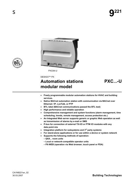
<strong>PXC</strong>64-U<br />
DESIGO PX<br />
<strong>Automation</strong> <strong>stations</strong><br />
<strong>modular</strong> <strong>model</strong><br />
<strong>PXC</strong>...-U<br />
• Freely programmable <strong>modular</strong> automation <strong>stations</strong> for HVAC and building<br />
services.<br />
• Native BACnet automation station with communication via BACnet over<br />
Ethernet / IP, LonTalk, or PTP<br />
• BTL label (BACnet communications passed the BTL test)<br />
• High performance and reliable operation<br />
• Comprehensive management and system functions (alarm management, time<br />
scheduling, trends, remote management, access protection etc.)<br />
• An Integrated Web server supports generic or graphic Web operation as well<br />
as transmission of alarms by e-mail or SMS<br />
• P-bus for connection of external TX-I/O or PTM I/O modules with any<br />
data point mix<br />
• Integration platform for subsystems and 3 rd party systems<br />
• For stand-alone applications or for use within a device or system network<br />
• Supports the following methods of operation:<br />
– QAX... room units<br />
– Local or network-compatible operator units<br />
– PX-WEB (operation via Web browser, touch panel or PDA)<br />
CA1N9221en_02<br />
30.03.2007 Building Technologies
Functions<br />
These freely programmable automation <strong>stations</strong> provide the infrastructure for the<br />
provision and processing of system-specific and application-specific functions.<br />
Apart from the freely programmable control functions these units comprise integrated<br />
convenient management functions such as:<br />
• Alarm management with alarm routing throughout the whole network. Three level<br />
alarm management (simple, basic and enhanced) with safety control transmission<br />
and automatic transmission monitoring<br />
• Time schedulers<br />
• Trend functions<br />
• Remote management functions<br />
• Access protection for the whole network with individually defined user profiles and<br />
categories<br />
Programming language<br />
These automation <strong>stations</strong> are freely programmable with the D-MAP programming<br />
language (follows closely CEN Standard 1131). All function blocks available in libraries<br />
are graphically linked with the plant operating programs.<br />
Communication<br />
BACnet / IP<br />
Communication is via Ethernet with the international standard BACnet protocol.<br />
Both peer-to-peer communications with other automation <strong>stations</strong> and connections to<br />
the PXM20-E operator units are supported.<br />
BACnet / LonTalk<br />
The devices communicate via an open LonTalk system in accordance with the international<br />
standard BACnet protocol. Both peer-to-peer communications with other<br />
automation <strong>stations</strong> and connections to the PXM20 operator units are supported.<br />
BACnet / PTP<br />
The devices communicate via the public telephone network in accordance with the<br />
international standard BACnet protocol.<br />
Types<br />
<strong>Automation</strong> <strong>stations</strong><br />
<strong>Automation</strong> station<br />
− for TX-I/O modules (up to 200 data points)<br />
− for PTM-I/O modules (up to 64 load units *)<br />
<strong>Automation</strong> station<br />
− for TX-I/O modules<br />
(more than 200 data points, see system limits)<br />
− for PTM-I/O modules (up to 128 load units *)<br />
Connecting cable (to connect an operator unit PXM10 or PXM20<br />
and for Firmware download)<br />
*) 1 load unit = 12.5 mA (see data sheets of the I/O modules PTM1…)<br />
System controllers<br />
System controller for the integration of DESIGO RXB room<br />
controllers and KNX 3 rd party devices<br />
System controller for the Integration of M-Bus, Modbus and SCL<br />
(up to 100 data points)<br />
(up to 400 data points)<br />
(SCL: up to 1000 data points, M- Bus and Modbus: up to 2000)<br />
Type<br />
<strong>PXC</strong>64-U<br />
<strong>PXC</strong>128-U<br />
PXA-C1<br />
Type<br />
<strong>PXC</strong>00-U<br />
+ PXA30-K11<br />
<strong>PXC</strong>00-U<br />
+ PXA30-RS<br />
… + PXA30-RS1<br />
… + PXA30-RS2<br />
.<br />
.<br />
.<br />
.<br />
.<br />
.<br />
.<br />
.<br />
.<br />
.<br />
.<br />
.<br />
.<br />
.<br />
.<br />
.<br />
.<br />
.<br />
.<br />
.<br />
.<br />
.<br />
.<br />
.<br />
.<br />
.<br />
.<br />
.<br />
2/12<br />
Siemens <strong>PXC</strong>...-U – <strong>Automation</strong> <strong>stations</strong> <strong>modular</strong> <strong>model</strong> CA1N9221en_02<br />
Building Technologies 30.03.2007
Compatibility<br />
Extension modules for automation <strong>stations</strong><br />
Function<br />
Interfaces<br />
Module PXA30-…<br />
T N NT W1 W2 W0<br />
Data sheet N9261 N9262 N9263 N9264 N9265 N9266<br />
Ethernet RJ45 X X X X X<br />
Serial RS232 X X X X X<br />
Network functions<br />
Configuration network RJ45 X X X X X<br />
BACnet / IP operation RJ45 X X X X X<br />
BACnet / LonTalk operation<br />
X<br />
PTP Dial-in DTS and X-Works RS232 1) X X X X X<br />
PPP Remote configuration RS232 1) X X X<br />
Remote management<br />
PTP Dial-in Desigo Insight RS232 1) X X X X X<br />
PPP via Ethernet RJ45 1) X X X<br />
Web-Functions<br />
Generic web functions X X X 2)<br />
Graphic web functions X X 2)<br />
Send alarms via SMS (RS232) X X X<br />
Send alarms via E-Mail (RJ45) X X X<br />
1)<br />
2)<br />
The modem connection can be configured as follows:<br />
− either for Remote management (DI and DTS – or X-WORKS)<br />
− or for remote management PX WEB generic / graphic and Alarming via SMS<br />
Web functions only for one automation station<br />
Extension modules for system controllers<br />
Function<br />
Interfaces<br />
Module<br />
PXA30-K11 PXA30-RS PXA30-RS1 PXA30-RS2<br />
Data sheet N9280 N9281 N9281 N9281<br />
KNX interface<br />
X<br />
Ethernet RJ45<br />
X<br />
Serial RS232 X X X<br />
Seral RS485 X X X<br />
Network functions<br />
Integration of RXB<br />
X<br />
Integration of Synco<br />
X<br />
Integration of KNX 3rd party devices<br />
X<br />
Integration of M-Bus counters 100 DP 400 DP 2000 DP<br />
Integration of Modbus 100 DP 400 DP 2000 DP<br />
Integration of SCL 100 DP 400 DP 1000 DP<br />
.<br />
.<br />
.<br />
.<br />
.<br />
.<br />
.<br />
.<br />
.<br />
.<br />
Siemens <strong>PXC</strong>...-U – <strong>Automation</strong> <strong>stations</strong> <strong>modular</strong> <strong>model</strong> CA1N9221en_02<br />
Building Technologies 30.03.2007<br />
3/12
TX-I/O-Modules<br />
Device Type Data sheet<br />
Digital input modules, 8 or 16 I/O points TXM1.8D, TXM1.16D CM2N8172<br />
Universal module without / with local override facility and LCD TXM1.8U TXM1.8U-ML CM2N8173<br />
Super universal module without / with local override facility and LCD TXM1.8X TXM1.8U-ML CM2N8174<br />
Relay module with without / local override facility TXM1.6R, TXM1.6R-M CM2N8175<br />
Power supply module 1.2 A, fuse 10A TXS1.12F10 CM2N8183<br />
Bus connection module, fuse 10A TXS1.EF10 CM2N8183<br />
P-Bus Interface module with power supply 1.2A, fuse 10A TXB1.P-BUS CM2N8180<br />
PTM-I/O-Modules<br />
.<br />
.<br />
.<br />
.<br />
.<br />
.<br />
.<br />
.<br />
.<br />
.<br />
.<br />
.<br />
.<br />
.<br />
.<br />
.<br />
.<br />
.<br />
.<br />
Device Type Data sheet<br />
I/O modules with basic functions measuring, signalling, switching and controlling PTM1... 8111 … 8171<br />
I/O OPEN modules for pumps PTM5... 866x<br />
I/O OPEN modules PTM1...,PTE 978x<br />
Operation<br />
There are various options for operation of the <strong>PXC</strong>…U automation <strong>stations</strong>:<br />
• QAX... room unit connected to the PPS2 interface. A maximum of five room units<br />
QAX… (not QAX5…) can be connected. Details on the PPS2 communication are<br />
described in the DESIGO Technical principles manual (chapter "I/O blocks", section<br />
"PPS2 addressing").<br />
• Local PXM10 operator unit, either plugged into the automation station or connected<br />
via PXA-C1 cable<br />
• Network-compatible PXM20 operator unit (BACnet / LonTalk)<br />
for operation of the local automation station or an automation station in a network,<br />
either plugged into the automation station, or connected via PXA-C1 cable<br />
• Network-compatible PXM20-E operator unit (BACnet / IP)<br />
for operation of the local automation station or an automation station in a network,<br />
either plugged into the automation station, or connected to the Ethernet network or<br />
an Ethernet switch.<br />
• PX-WEB: The PXA30-W… extension module is used to activate the Web server,<br />
allowing operation with a Web browser, a touch panel or a PDA.<br />
The transfer of alarms via SMS or e-mail can be configured in the automation<br />
station.<br />
_<br />
_<br />
_<br />
4/12<br />
Siemens <strong>PXC</strong>...-U – <strong>Automation</strong> <strong>stations</strong> <strong>modular</strong> <strong>model</strong> CA1N9221en_02<br />
Building Technologies 30.03.2007
Design<br />
6<br />
7<br />
8<br />
00255a<br />
9<br />
1<br />
4<br />
5<br />
2<br />
3<br />
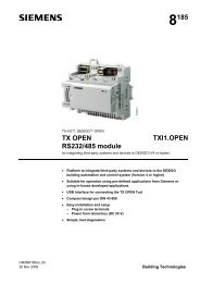
1 Plug-in unit<br />
2 Front cover<br />
(a PXM... operator unit can be fitted instead of the front cover)<br />
3 Battery<br />
4/5 Extension modules<br />
6 Device socket<br />
7 Plug-in connection for automation station for device supply and bus<br />
electronics<br />
8 Housing with pcb for device supply<br />
9 Plug-in terminal blocks with reversible support bar (here used for wall<br />
mounting)<br />
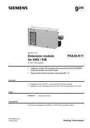
LED indicators<br />
00256 A<br />
Service pin<br />
COM1<br />
COM2<br />
RUN STA INFO TX SERVICE TX SERVICE<br />
Siemens <strong>PXC</strong>...-U – <strong>Automation</strong> <strong>stations</strong> <strong>modular</strong> <strong>model</strong> CA1N9221en_02<br />
Building Technologies 30.03.2007<br />
5/12
Concerned LED Color Status Function<br />
<strong>Automation</strong> station RUN Green<br />
Red<br />
Continuously off<br />
Continuously on<br />
Continuously on<br />
STATUS Red Continuously off<br />
Continuously on<br />
No supply<br />
Supply OK, firmware OK<br />
RESET key pressed<br />
Normal operation<br />
Hardware fault detected during self-test or<br />
automation station in "coma" operating state<br />
Quick flashes No validly licensed firmware<br />
INFO Red Freely programmable<br />
Data traffic LONWORKS bus TX COM1 Yellow Flashing Data traffic on LONWORKS bus<br />
COM2 Yellow Inactive<br />
SERVICE<br />
COM1<br />
Red Continuously off<br />
Flashing<br />
Flashing acc. to wink<br />
command pattern *)<br />
Continuously on<br />
LONWORKS node is configured<br />
LONWORKS node is not configured<br />
Physical identification of automation station<br />
after receiving wink command<br />
LONWORKS chip defective or service key was<br />
pressed again<br />
COM2 Red Inactive<br />
Data traffic Ethernet / IP TX COM1 Yellow Inactive<br />
(PXA30-N..., PXA30-W...) COM2 Yellow Flashing Sends Ethernet data<br />
SERVICE<br />
COM1 Red Inactive<br />
COM2 Red Continuously off<br />
Flashing slowly<br />
Continuously on<br />
Ethernet OK<br />
IP address not configured<br />
No link pulse<br />
*) Wink command rhythm pattern:<br />
21s<br />
00408<br />
5 Hz 5 Hz<br />
2s<br />
1s<br />
2s<br />
1s<br />
Mounting instructions<br />
The <strong>modular</strong> automation <strong>stations</strong> are particularly suitable for control panel front<br />
mounting as well as flush-panel and wall mounting.<br />
For control panel front mounting the device socket is held in place by clamps at all four<br />
corners (no tools required for mounting). The upper housing is fixed to the device<br />
socket with two screws.<br />
For flush panel mounting the plug-in terminal blocks can be repositioned whilst at the<br />
same time reversing the support bars to enable front access. The support bars absorb<br />
the screw force and also provide the means of fixing the device to the wall.<br />
Instead of the front cover a PXM... operator unit can be fitted on the <strong>modular</strong> automation<br />
station.<br />
Note<br />
For PXM20-E mounting (ethernet cable) see the mounting instructions delivered with<br />
the operator unit!<br />
STOP<br />
Note!<br />
• Insert the PXA30… extension module fully into its socket (to a depth of 1.5 mm),<br />
using slight force. Then check that the plug is safely snapped on to ensure safe<br />
and smooth functioning.<br />
• Do not touch the connector pins (electrostatic discharge)<br />
6/12<br />
Siemens <strong>PXC</strong>...-U – <strong>Automation</strong> <strong>stations</strong> <strong>modular</strong> <strong>model</strong> CA1N9221en_02<br />
Building Technologies 30.03.2007
Commissioning<br />
In order to prevent equipment damage and/or personal injuries always follow local<br />
safety regulations and the required safety standards.<br />
STOP<br />
Caution!<br />
Electronic parts may be damaged if the upper housing is inserted or<br />
disconnected with the supply voltage switched on (hot plugging).<br />
Loading plant operating<br />
program<br />
Setting parameters and<br />
configurations<br />
Download the plant operating program to the automation station with the PX Design<br />
tool in the DESIGO TOOLSET, locally via the RJ45 connector of the AS or via the<br />
LONWORKS bus.<br />
Use the PX Design tool in the DESIGO TOOLSET for setting the control parameters<br />
and the configuration data. Data visible in the network can also be changed with the<br />
PXM… operator unit.<br />
Wiring test<br />
It is possible to test field devices and the wiring as soon as the power supply is<br />
connected, without first downloading the plant operating program.<br />
The test is carried out with a PXM20 or PXM20-E operator unit.<br />
Network connection<br />
The network addresses are configured with the DESIGO TOOLSET. In order to provide<br />
a unique identification in the LONWORKS network press the service pin with a sharp<br />
implement (COM1 on the front, see page 4) or send a wink command to the relevant<br />
automation station (service LED flashes).<br />
Service functions<br />
Three service buttons are provide under the front cover:<br />
A B RESET<br />
00257<br />
A<br />
Force<br />
Firmware<br />
Download<br />
Connected to<br />
LONWORKS -<br />
Bus<br />
If this key is pressed during a restart (Powerfail)<br />
the current D-MAP program is deleted<br />
from the FLASH.<br />
The automation station waits a short while for<br />
the signal to activate the FWLoader and then<br />
starts the automation station..<br />
If this key is pressed for >5 s, the automation<br />
station waits for a firmware download via<br />
Ethernet.<br />
Pressing this button during a restart forces a<br />
cold start.<br />
Connected to<br />
Ethernet / IP<br />
B<br />
Force<br />
Cold Start<br />
RESET<br />
Forces a restart<br />
Maintenance<br />
Battery life<br />
Battery change<br />
Lithium batteries usually have a life span of at least four years. The automation station<br />
automatically sends a system event in order to indicate a low charge.<br />
After the "Battery low" event there are several months of remaining life span.<br />
To change the battery, remove the front cover. As long as the supply voltage is<br />
connected, the battery may be removed for unlimited time.<br />
STOP<br />
Caution!<br />
To prevent hardware damage by electrostatic discharge (ESD), a wrist strap with earth<br />
cable must be used during the battery change.<br />
7/12<br />
Siemens <strong>PXC</strong>...-U – <strong>Automation</strong> <strong>stations</strong> <strong>modular</strong> <strong>model</strong> CA1N9221en_02<br />
Building Technologies 30.03.2007
Disposal<br />
The unit contains electric and electronic components and must not be disposed of with<br />
domestic waste. Lithium battery, printed circuit board and housing must be disposed of<br />
separately<br />
The local and actual regulations must be observed.<br />
Technical data<br />
General device data Operating voltage AC 24 V ± 20 %<br />
Safety extra-low voltage SELV<br />
Protective extra-low voltage PELV HD 384<br />
Frequency<br />
50/60 Hz<br />
Current consumption<br />
4 A<br />
Power consumption <strong>PXC</strong>00-U 45 VA<br />
<strong>PXC</strong>64-U 45 VA<br />
<strong>PXC</strong>128-U 95 VA<br />
Internal fuse<br />
Thermic, automatic reset<br />
.<br />
.<br />
.<br />
.<br />
.<br />
Operating data Processor MOTOROLA Power PC 32 Bit<br />
Memory space FLASH<br />
16 MByte<br />
SDRAM<br />
32 MByte<br />
SRAM<br />
2 MByte<br />
Data backup in case of power failure<br />
Applications, parameter (FLASH)<br />
> 10 years<br />
Run-time data (battery)<br />
> 4 years (battery)<br />
Ethernet interface Interface type 100BaseTX, IEEE 802.3 compatible<br />
(extension modules Bit rate 10 / 100 Mbit/s, auto-sensing<br />
PXA30.N, PXA30.W…) Protocol BACnet over UDP/IP<br />
Connection<br />
RJ45 socket, screened<br />
Wiring Cable type<br />
Standard at least CAT5<br />
UTP (Unshielded Twisted Pair)<br />
or STP (Shielded Twisted Pair)<br />
Cable length<br />
Max. 100m<br />
LONWORKS bus interface Network TP/FT-10<br />
Baud rate<br />
78 kBit/s<br />
Protocol<br />
BACnet<br />
Interface chip<br />
Echelon Processor TMPN3150B1AF<br />
Wiring Cable type<br />
ConCab or CAT5<br />
Cable length<br />
See installation guide, CA110396<br />
Serial interface Interface type RS232<br />
Baud rate / Data bits / Stop bit 57 600 bps / 8 / 1<br />
Parity / Flow control<br />
None / None<br />
Wiring Cable type<br />
9-core standard screened cable<br />
Cable length<br />
Max. 3m<br />
P-bus interface Polling cycle at I/O modules 0.3 s<br />
(<strong>PXC</strong>64-U, <strong>PXC</strong>128-U) Transmission speed 62.5 kBaud<br />
Signal level<br />
DC +23 V and 0/–5 V<br />
Wiring Cross-section Min. 3 x 0.75 mm 2<br />
Cable length<br />
Max. 50 m<br />
Cable length (special requirements) Max. 200 m<br />
.<br />
.<br />
.<br />
.<br />
.<br />
.<br />
8/12<br />
Siemens <strong>PXC</strong>...-U – <strong>Automation</strong> <strong>stations</strong> <strong>modular</strong> <strong>model</strong> CA1N9221en_02<br />
Building Technologies 30.03.2007
Interface, room units Interface type PPS2<br />
Supply class 4<br />
PPS2 baud rate<br />
4.8 kBit/s<br />
Wiring Cable type<br />
4-core, twisted pair, unscreened<br />
Capacitance per unit length<br />
Max. 56 nF/km<br />
Single cable length Max. 125 m where A = 1.0 mm 2<br />
Connecting cable PXM10 or PXM20 / DESIGO TOOLSET Max. 3 m<br />
Plug-in screw terminal Power supply and signals Stranded of solid conductors,<br />
0.25 … 2.5 mm 2 or 2 x 1.5 mm 2<br />
LONWORKS bus<br />
Stranded or solid conductors,<br />
2 x 1.0 mm 2<br />
Housing protection standard Protection standard to EN 60529 IP 30<br />
Protection class Isolation protection class II<br />
Ambient conditions Operation Class 3K5 to IEC 721<br />
Temperature 0 ... 50 °C<br />
Humidity<br />
< 85 % rh<br />
Transport Class 2K3 to IEC 721<br />
Temperature – 25 ... 65 °C<br />
Humidity<br />
< 95 % rh<br />
Industry standards Meets all requirements for B-AAC BACnet Implementation Conformance<br />
Statement (PICS)<br />
Product safety<br />
Automatic electronic controls for<br />
household and similar use EN 60730-1<br />
Special requirements for energy controllers EN 60730-2-11<br />
Electromagnetic compatibility<br />
Interference immunity EN 61000-6-2<br />
Emitted interference EN 61000-6-2<br />
Meets requirements for CE marking:<br />
Electromagnetic compatibility<br />
89/336/EEC<br />
Low Voltage Directive<br />
2006/95/EEC<br />
Dimensions<br />
See “Dimensions”<br />
Weight Without / with packaging 0.96 / 1016 kg<br />
.<br />
.<br />
.<br />
Siemens <strong>PXC</strong>...-U – <strong>Automation</strong> <strong>stations</strong> <strong>modular</strong> <strong>model</strong> CA1N9221en_02<br />
Building Technologies 30.03.2007<br />
9/12
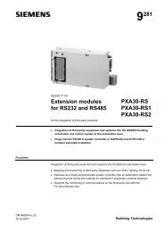
Connection terminals<br />
<strong>PXC</strong>64-U<br />
00341<br />
C1<br />
C2<br />
8<br />
C3<br />
C4<br />
S<br />
9<br />
S<br />
CLA<br />
10<br />
CLB<br />
G<br />
1<br />
G0<br />
PD<br />
2 PU<br />
PC<br />
CP+<br />
4<br />
CP–<br />
MMI/TOOL<br />
G/G0<br />
Supply voltage AC 24 V/PELV<br />
PD P-bus Synchronisation cable<br />
PU<br />
Data transmission line, bi-directional<br />
PC Reference voltage DC 23 V (against G0)<br />
CP+/CP–<br />
CLA/CLB<br />
HMI/TOOL<br />
PPS2 bus (for QAX... room operator units)<br />
LONWORKS bus (inactive, if a PXA30-N... or PXA30-W... extension<br />
module for Ethernet is plugged in)<br />
RJ45 socket on front cover<br />
(for PXM10 / PXM20 operator unit or DESIGO TOOLSET)<br />
<strong>PXC</strong>128-U<br />
The PXA-C128-U includes a second P-bus:<br />
• Terminals P-bus 1 PD1, PU1 and PC1<br />
• Terminals P-bus 2 PD2, PU2 and PC2<br />
<strong>PXC</strong>00-U<br />
The automation station <strong>PXC</strong>00-U does not have an active P-Bus interface<br />
Tool socket<br />
Standard RJ45 tool socket for LONWORKS devices.<br />
1 2345678<br />
3206Z01<br />
1 LONWORKS, Data A (CLA) *)<br />
2 LONWORKS, Data B (CLB) *)<br />
3 G0, GND<br />
4 G/Plus<br />
5 Unoccupied<br />
6 Unoccupied<br />
7 COM1/TxD<br />
8 COM1/RxD<br />
*) The LONWORKS pins are inactive, if a PXA30-N... or PXA30-W... extension module<br />
for Ethernet is plugged in, and in the automation station <strong>PXC</strong>00-U)<br />
Connection diagrams<br />
Connection of field devices: see mounting and installation manual for I/O modules and<br />
P-bus (CM2M8102).<br />
10/12<br />
Siemens <strong>PXC</strong>...-U – <strong>Automation</strong> <strong>stations</strong> <strong>modular</strong> <strong>model</strong> CA1N9221en_02<br />
Building Technologies 30.03.2007
Dimensions<br />
Front mounting<br />
max R2<br />
137<br />
0<br />
+1<br />
17<br />
55<br />
22.5<br />
min. 40 mm<br />
00232 K<br />
24<br />
25<br />
PXM...<br />
150<br />
138<br />
+1<br />
138 0<br />
15<br />
27<br />
109<br />
136<br />
min. 80 mm<br />
210<br />
For PXM20-E only *)<br />
min. 100 mm<br />
*) This hole is required for the Ethernet cable<br />
when an operator unit PXM20-E is mounted<br />
on top of the automation station.<br />
Wall mounting<br />
137<br />
150<br />
17<br />
55<br />
min. 40 mm<br />
00233 K<br />
PXM...<br />
81<br />
22,7 18 40,7<br />
14,5<br />
15<br />
27<br />
109<br />
136<br />
min. 80 mm<br />
210<br />
5,2<br />
124,5<br />
min. 100 mm<br />
11/12<br />
Siemens <strong>PXC</strong>...-U – <strong>Automation</strong> <strong>stations</strong> <strong>modular</strong> <strong>model</strong> CA1N9221en_02<br />
Building Technologies 30.03.2007
12/12<br />
© 2001 - 2007 Siemens Switzerland Ltd. Subject to change<br />
Siemens <strong>PXC</strong>...-U – <strong>Automation</strong> <strong>stations</strong> <strong>modular</strong> <strong>model</strong> CA1N9221en_02<br />
Building Technologies 30.03.2007