

FT53 Cast Iron Ball Float Steam Trap with Flanged ... - Spirax Sarco
FT53 Cast Iron Ball Float Steam Trap with Flanged ... - Spirax Sarco
FT53 Cast Iron Ball Float Steam Trap with Flanged ... - Spirax Sarco

Create successful ePaper yourself
Turn your PDF publications into a flip-book with our unique Google optimized e-Paper software.
Cert. No. LRQ 0963008<br />
ISO 9001<br />
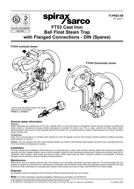
<strong>FT53</strong> <strong>Cast</strong> <strong>Iron</strong><br />
<strong>Ball</strong> <strong>Float</strong> <strong>Steam</strong> <strong>Trap</strong><br />
<strong>with</strong> <strong>Flanged</strong> Connections - DIN (Spares)<br />
<strong>FT53</strong>V (vertical) shown<br />
<strong>Trap</strong>s having the optional steam lock release<br />
will have the nomenclature<br />
<strong>FT53</strong>V-C or <strong>FT53</strong>H-C<br />
TI-P603-08<br />
ST Issue 1<br />
General safety information<br />
Pressure<br />
Before attempting any maintenance on the trap, consider what is or may have been in the pipeline. Ensure that any pressure is isolated and<br />
safely vented to atmospheric pressure before attempting to maintain the steam trap. This is easily achieved by fitting <strong>Spirax</strong> <strong>Sarco</strong><br />
depressurisation valves type DV (see separate literature for details). Do not assume that the system is depressurised even when a pressure<br />
gauge indicates zero.<br />
Temperature<br />
Allow time for temperature to normalise after isolation to avoid the danger of burns and consider whether protective clothing (including<br />
safety glasses) is required.<br />
Caution: The cover gasket and main valve assembly gasket may contain a thin stainless steel support ring which may cause physical injury<br />
if it is not handled and disposed of carefully.<br />
Installation<br />
The trap is designed for installation <strong>with</strong> the float arm in a horizontal plane so that it rises and falls vertically, ideally <strong>with</strong> a drop leg immediately<br />
preceding the trap. Suitable isolation valves must be installed to allow for safe maintenance/replacement. Remove all protective caps prior to<br />
installation. Open isolation valves slowly and check for leaks. Where steam traps are fitted in exposed conditions, the possibility of freezing<br />
damage may be reduced by thermal insulation/draining/isolation.<br />
Maintenance<br />
Maintenance can be completed <strong>with</strong> the trap in the pipeline, once the safety procedures have been observed. It is recommended that new<br />
gaskets and spares are used whenever maintenance is undertaken. Ensure that the correct tools and necessary protective equipment are used<br />
at all times. When maintenance is complete open isolation valves slowly and check for leaks. See IM-P603-03 for further details.<br />
Disposal<br />
No ecological hazard is anticipated <strong>with</strong> the disposal of these products provided due care is taken.<br />
Note: For further information regarding Installation, Maintenance and Safety see IM-P603-03<br />
<strong>FT53</strong>H (horizontal) shown<br />
Local regulations may restrict the use of this product to below the conditions quoted.<br />
In the interests of development and improvement of the product, we reserve the right to change the specification. © Copyright 2002
Spare parts<br />
The spare parts available are shown in heavy outline. Parts shown<br />
in a broken line are not supplied as spares. For further technical<br />
information see TI-P603-07.<br />
Available spares<br />
Main valve assembly <strong>with</strong> erosion deflector 5, 7, 10, 16<br />
<strong>Ball</strong> float 8<br />
Air vent assembly 17, 18, 24, 25, 26<br />
Complete set of gaskets (packet of 3) 3, 7, 18, 20<br />
<strong>Steam</strong> lock release and air vent assembly<br />
17, 18, 19, 20, 21,<br />
22, 23, 24, 25, 26<br />
How to order spares<br />
Always order spare parts by using the description given in the<br />
column headed 'Available spares' and state the size, Model No.,<br />
orientation i.e. horizontal (H) or vertical (V) and pressure rating of<br />
the trap.<br />
Example: 1 - Main valve assembly for a DN40 <strong>FT53</strong>H-4.5 ball float<br />
steam trap. For operating pressures up to 4.5 bar.<br />
Note: If the product has the optional steam lock release fitted the<br />
nomenclature would be <strong>FT53</strong>H-4.5-C<br />
<strong>FT53</strong>H shown<br />
Recommended tightening torques<br />
or<br />
Item No. N m<br />
mm<br />
<strong>FT53</strong>H Bolt 24 A/F M16 x 55 150 - 165<br />
4<br />
FT5<br />
Stud<br />
Nut 24 A/F<br />
M16<br />
M16<br />
70 - 80<br />
150 - 165<br />
5 Valve seat 17 A/F M12 50 - 55<br />
16 Erosion deflector bolts 10 A/F M6 x 10 10 - 12<br />
17 Air vent seat 17 A/F 50 - 55<br />
19 (SLR sub-assembly) 19 A/F 40 - 45<br />
21 (SLR retaining nut) 13 A/F 4 - 5<br />
3<br />
26<br />
25<br />
Air vent assembly<br />
24<br />
17 18<br />
8 5 16 10 7<br />
Main valve assembly<br />
<strong>with</strong> erosion deflector<br />
22 23<br />
<strong>Steam</strong> lock release<br />
assembly<br />
20 19 21<br />
<strong>FT53</strong> <strong>Cast</strong> <strong>Iron</strong> <strong>Ball</strong> <strong>Float</strong> <strong>Steam</strong> <strong>Trap</strong><br />
<strong>with</strong> <strong>Flanged</strong> Connections - DIN (Spares) TI-P603-08 ST Issue 1


